EP3064164B1 - Hand-held dual spherical antenna system - Google Patents
Hand-held dual spherical antenna system Download PDFInfo
- Publication number
- EP3064164B1 EP3064164B1 EP16158315.8A EP16158315A EP3064164B1 EP 3064164 B1 EP3064164 B1 EP 3064164B1 EP 16158315 A EP16158315 A EP 16158315A EP 3064164 B1 EP3064164 B1 EP 3064164B1
- Authority
- EP
- European Patent Office
- Prior art keywords
- antenna elements
- coil
- interrogation
- signals
- transmit
- Prior art date
- Legal status (The legal status is an assumption and is not a legal conclusion. Google has not performed a legal analysis and makes no representation as to the accuracy of the status listed.)
- Active
Links
- 230000009977 dual effect Effects 0.000 title 1
- 238000001514 detection method Methods 0.000 claims description 257
- 239000000523 sample Substances 0.000 claims description 131
- 230000004044 response Effects 0.000 claims description 80
- 238000000034 method Methods 0.000 claims description 76
- 238000005259 measurement Methods 0.000 claims description 43
- 239000004020 conductor Substances 0.000 claims description 40
- 230000003068 static effect Effects 0.000 claims description 36
- 230000000712 assembly Effects 0.000 claims description 33
- 238000000429 assembly Methods 0.000 claims description 33
- 230000000007 visual effect Effects 0.000 claims description 8
- 238000010586 diagram Methods 0.000 description 27
- 230000008878 coupling Effects 0.000 description 15
- 238000010168 coupling process Methods 0.000 description 15
- 238000005859 coupling reaction Methods 0.000 description 15
- 239000003990 capacitor Substances 0.000 description 14
- 229910000859 α-Fe Inorganic materials 0.000 description 13
- 238000013459 approach Methods 0.000 description 12
- 230000008569 process Effects 0.000 description 10
- 238000001356 surgical procedure Methods 0.000 description 10
- 230000001360 synchronised effect Effects 0.000 description 8
- 230000001276 controlling effect Effects 0.000 description 6
- 239000000463 material Substances 0.000 description 6
- 238000012360 testing method Methods 0.000 description 6
- 230000009471 action Effects 0.000 description 5
- 239000002775 capsule Substances 0.000 description 5
- 238000004891 communication Methods 0.000 description 5
- 238000001914 filtration Methods 0.000 description 5
- 238000004519 manufacturing process Methods 0.000 description 5
- 230000002093 peripheral effect Effects 0.000 description 5
- 230000000717 retained effect Effects 0.000 description 5
- 238000005070 sampling Methods 0.000 description 5
- 239000004593 Epoxy Substances 0.000 description 3
- 239000000853 adhesive Substances 0.000 description 3
- 230000001070 adhesive effect Effects 0.000 description 3
- 230000005540 biological transmission Effects 0.000 description 3
- 239000008393 encapsulating agent Substances 0.000 description 3
- 230000006870 function Effects 0.000 description 3
- 239000010813 municipal solid waste Substances 0.000 description 3
- 238000011084 recovery Methods 0.000 description 3
- 230000002829 reductive effect Effects 0.000 description 3
- 238000001228 spectrum Methods 0.000 description 3
- 230000004397 blinking Effects 0.000 description 2
- 230000001419 dependent effect Effects 0.000 description 2
- 238000013461 design Methods 0.000 description 2
- 210000003127 knee Anatomy 0.000 description 2
- 229910052751 metal Inorganic materials 0.000 description 2
- 239000002184 metal Substances 0.000 description 2
- 230000037361 pathway Effects 0.000 description 2
- 230000035807 sensation Effects 0.000 description 2
- 230000001953 sensory effect Effects 0.000 description 2
- 229910000679 solder Inorganic materials 0.000 description 2
- 239000007787 solid Substances 0.000 description 2
- 238000003860 storage Methods 0.000 description 2
- 241001522296 Erithacus rubecula Species 0.000 description 1
- 239000004831 Hot glue Substances 0.000 description 1
- 239000004743 Polypropylene Substances 0.000 description 1
- 229910001035 Soft ferrite Inorganic materials 0.000 description 1
- 230000004913 activation Effects 0.000 description 1
- 230000002411 adverse Effects 0.000 description 1
- 210000003423 ankle Anatomy 0.000 description 1
- 230000009118 appropriate response Effects 0.000 description 1
- 230000008901 benefit Effects 0.000 description 1
- 210000001124 body fluid Anatomy 0.000 description 1
- 239000003985 ceramic capacitor Substances 0.000 description 1
- 238000006243 chemical reaction Methods 0.000 description 1
- 239000011248 coating agent Substances 0.000 description 1
- 238000000576 coating method Methods 0.000 description 1
- 230000001427 coherent effect Effects 0.000 description 1
- 239000003086 colorant Substances 0.000 description 1
- 230000002860 competitive effect Effects 0.000 description 1
- 238000004590 computer program Methods 0.000 description 1
- 238000005520 cutting process Methods 0.000 description 1
- 230000004069 differentiation Effects 0.000 description 1
- 238000009826 distribution Methods 0.000 description 1
- 230000005284 excitation Effects 0.000 description 1
- 239000004744 fabric Substances 0.000 description 1
- 238000007667 floating Methods 0.000 description 1
- 239000012530 fluid Substances 0.000 description 1
- 210000002683 foot Anatomy 0.000 description 1
- 210000001624 hip Anatomy 0.000 description 1
- 230000001939 inductive effect Effects 0.000 description 1
- 230000003993 interaction Effects 0.000 description 1
- 238000003475 lamination Methods 0.000 description 1
- 239000004973 liquid crystal related substance Substances 0.000 description 1
- 238000002504 lithotomy Methods 0.000 description 1
- 230000007246 mechanism Effects 0.000 description 1
- 238000012986 modification Methods 0.000 description 1
- 230000004048 modification Effects 0.000 description 1
- 238000012544 monitoring process Methods 0.000 description 1
- 210000003739 neck Anatomy 0.000 description 1
- QELJHCBNGDEXLD-UHFFFAOYSA-N nickel zinc Chemical compound [Ni].[Zn] QELJHCBNGDEXLD-UHFFFAOYSA-N 0.000 description 1
- 210000003049 pelvic bone Anatomy 0.000 description 1
- 230000000737 periodic effect Effects 0.000 description 1
- 239000004033 plastic Substances 0.000 description 1
- 229920000642 polymer Polymers 0.000 description 1
- -1 polypropylene Polymers 0.000 description 1
- 229920001155 polypropylene Polymers 0.000 description 1
- AEHJMNVBLRLZKK-UHFFFAOYSA-N pyridalyl Chemical compound N1=CC(C(F)(F)F)=CC=C1OCCCOC1=C(Cl)C=C(OCC=C(Cl)Cl)C=C1Cl AEHJMNVBLRLZKK-UHFFFAOYSA-N 0.000 description 1
- 230000001105 regulatory effect Effects 0.000 description 1
- 229920005989 resin Polymers 0.000 description 1
- 239000011347 resin Substances 0.000 description 1
- 238000007789 sealing Methods 0.000 description 1
- 230000035945 sensitivity Effects 0.000 description 1
- 210000002832 shoulder Anatomy 0.000 description 1
- 229910052709 silver Inorganic materials 0.000 description 1
- 229910052718 tin Inorganic materials 0.000 description 1
- 238000003466 welding Methods 0.000 description 1
Images


Classifications
-
- A—HUMAN NECESSITIES
- A61—MEDICAL OR VETERINARY SCIENCE; HYGIENE
- A61B—DIAGNOSIS; SURGERY; IDENTIFICATION
- A61B5/00—Measuring for diagnostic purposes; Identification of persons
- A61B5/06—Devices, other than using radiation, for detecting or locating foreign bodies ; determining position of probes within or on the body of the patient
- A61B5/061—Determining position of a probe within the body employing means separate from the probe, e.g. sensing internal probe position employing impedance electrodes on the surface of the body
- A61B5/064—Determining position of a probe within the body employing means separate from the probe, e.g. sensing internal probe position employing impedance electrodes on the surface of the body using markers
-
- G—PHYSICS
- G06—COMPUTING; CALCULATING OR COUNTING
- G06K—GRAPHICAL DATA READING; PRESENTATION OF DATA; RECORD CARRIERS; HANDLING RECORD CARRIERS
- G06K7/00—Methods or arrangements for sensing record carriers, e.g. for reading patterns
- G06K7/10—Methods or arrangements for sensing record carriers, e.g. for reading patterns by electromagnetic radiation, e.g. optical sensing; by corpuscular radiation
- G06K7/10009—Methods or arrangements for sensing record carriers, e.g. for reading patterns by electromagnetic radiation, e.g. optical sensing; by corpuscular radiation sensing by radiation using wavelengths larger than 0.1 mm, e.g. radio-waves or microwaves
- G06K7/10366—Methods or arrangements for sensing record carriers, e.g. for reading patterns by electromagnetic radiation, e.g. optical sensing; by corpuscular radiation sensing by radiation using wavelengths larger than 0.1 mm, e.g. radio-waves or microwaves the interrogation device being adapted for miscellaneous applications
- G06K7/10376—Methods or arrangements for sensing record carriers, e.g. for reading patterns by electromagnetic radiation, e.g. optical sensing; by corpuscular radiation sensing by radiation using wavelengths larger than 0.1 mm, e.g. radio-waves or microwaves the interrogation device being adapted for miscellaneous applications the interrogation device being adapted for being moveable
- G06K7/10386—Methods or arrangements for sensing record carriers, e.g. for reading patterns by electromagnetic radiation, e.g. optical sensing; by corpuscular radiation sensing by radiation using wavelengths larger than 0.1 mm, e.g. radio-waves or microwaves the interrogation device being adapted for miscellaneous applications the interrogation device being adapted for being moveable the interrogation device being of the portable or hand-handheld type, e.g. incorporated in ubiquitous hand-held devices such as PDA or mobile phone, or in the form of a portable dedicated RFID reader
-
- A—HUMAN NECESSITIES
- A61—MEDICAL OR VETERINARY SCIENCE; HYGIENE
- A61B—DIAGNOSIS; SURGERY; IDENTIFICATION
- A61B90/00—Instruments, implements or accessories specially adapted for surgery or diagnosis and not covered by any of the groups A61B1/00 - A61B50/00, e.g. for luxation treatment or for protecting wound edges
- A61B90/90—Identification means for patients or instruments, e.g. tags
- A61B90/98—Identification means for patients or instruments, e.g. tags using electromagnetic means, e.g. transponders
-
- G—PHYSICS
- G06—COMPUTING; CALCULATING OR COUNTING
- G06K—GRAPHICAL DATA READING; PRESENTATION OF DATA; RECORD CARRIERS; HANDLING RECORD CARRIERS
- G06K7/00—Methods or arrangements for sensing record carriers, e.g. for reading patterns
- G06K7/10—Methods or arrangements for sensing record carriers, e.g. for reading patterns by electromagnetic radiation, e.g. optical sensing; by corpuscular radiation
- G06K7/10009—Methods or arrangements for sensing record carriers, e.g. for reading patterns by electromagnetic radiation, e.g. optical sensing; by corpuscular radiation sensing by radiation using wavelengths larger than 0.1 mm, e.g. radio-waves or microwaves
- G06K7/10316—Methods or arrangements for sensing record carriers, e.g. for reading patterns by electromagnetic radiation, e.g. optical sensing; by corpuscular radiation sensing by radiation using wavelengths larger than 0.1 mm, e.g. radio-waves or microwaves using at least one antenna particularly designed for interrogating the wireless record carriers
-
- H—ELECTRICITY
- H01—ELECTRIC ELEMENTS
- H01Q—ANTENNAS, i.e. RADIO AERIALS
- H01Q1/00—Details of, or arrangements associated with, antennas
- H01Q1/12—Supports; Mounting means
- H01Q1/22—Supports; Mounting means by structural association with other equipment or articles
- H01Q1/2208—Supports; Mounting means by structural association with other equipment or articles associated with components used in interrogation type services, i.e. in systems for information exchange between an interrogator/reader and a tag/transponder, e.g. in Radio Frequency Identification [RFID] systems
-
- H—ELECTRICITY
- H01—ELECTRIC ELEMENTS
- H01Q—ANTENNAS, i.e. RADIO AERIALS
- H01Q21/00—Antenna arrays or systems
- H01Q21/24—Combinations of antenna units polarised in different directions for transmitting or receiving circularly and elliptically polarised waves or waves linearly polarised in any direction
-
- H—ELECTRICITY
- H01—ELECTRIC ELEMENTS
- H01Q—ANTENNAS, i.e. RADIO AERIALS
- H01Q7/00—Loop antennas with a substantially uniform current distribution around the loop and having a directional radiation pattern in a plane perpendicular to the plane of the loop
-
- A—HUMAN NECESSITIES
- A61—MEDICAL OR VETERINARY SCIENCE; HYGIENE
- A61B—DIAGNOSIS; SURGERY; IDENTIFICATION
- A61B34/00—Computer-aided surgery; Manipulators or robots specially adapted for use in surgery
- A61B34/20—Surgical navigation systems; Devices for tracking or guiding surgical instruments, e.g. for frameless stereotaxis
- A61B2034/2046—Tracking techniques
- A61B2034/2051—Electromagnetic tracking systems
-
- A—HUMAN NECESSITIES
- A61—MEDICAL OR VETERINARY SCIENCE; HYGIENE
- A61B—DIAGNOSIS; SURGERY; IDENTIFICATION
- A61B90/00—Instruments, implements or accessories specially adapted for surgery or diagnosis and not covered by any of the groups A61B1/00 - A61B50/00, e.g. for luxation treatment or for protecting wound edges
- A61B90/08—Accessories or related features not otherwise provided for
- A61B2090/0804—Counting number of instruments used; Instrument detectors
-
- A—HUMAN NECESSITIES
- A61—MEDICAL OR VETERINARY SCIENCE; HYGIENE
- A61B—DIAGNOSIS; SURGERY; IDENTIFICATION
- A61B90/00—Instruments, implements or accessories specially adapted for surgery or diagnosis and not covered by any of the groups A61B1/00 - A61B50/00, e.g. for luxation treatment or for protecting wound edges
- A61B90/39—Markers, e.g. radio-opaque or breast lesions markers
- A61B2090/3966—Radiopaque markers visible in an X-ray image
-
- A—HUMAN NECESSITIES
- A61—MEDICAL OR VETERINARY SCIENCE; HYGIENE
- A61B—DIAGNOSIS; SURGERY; IDENTIFICATION
- A61B2505/00—Evaluating, monitoring or diagnosing in the context of a particular type of medical care
- A61B2505/05—Surgical care
-
- H—ELECTRICITY
- H01—ELECTRIC ELEMENTS
- H01F—MAGNETS; INDUCTANCES; TRANSFORMERS; SELECTION OF MATERIALS FOR THEIR MAGNETIC PROPERTIES
- H01F5/00—Coils
- H01F5/02—Coils wound on non-magnetic supports, e.g. formers
- H01F2005/027—Coils wound on non-magnetic supports, e.g. formers wound on formers for receiving several coils with perpendicular winding axes, e.g. for antennae or inductive power transfer
Definitions
- This disclosure generally relates to the detection of the presence or absence of objects tagged with transponders, which may, for example, allow the detection of retained medical supplies during medical procedures.
- the objects may take a variety of forms.
- the objects may take the form of instruments, for instance scalpels, scissors, forceps, hemostats, and/or clamps.
- the objects may take the form of related accessories and/or disposable objects, for instance surgical sponges, gauzes, and/or pads. Failure to locate an object before closing the patient may require additional surgery, and in some instances may have serious adverse medical consequences.
- Some hospitals have instituted procedures which include checklists or requiring multiple counts to be performed to track the use and return of objects during surgery. Such a manual approach is inefficient, requiring the time of highly trained personnel, and is prone to error.
- Another approach employs transponders and a wireless interrogation and detection system.
- the interrogation and detection system includes a transmitter that emits pulsed wideband wireless signals (e.g. , radio or microwave frequency) and a detector for detecting wireless signals returned by the transponders in response to the emitted pulsed wideband signals.
- pulsed wideband wireless signals e.g. , radio or microwave frequency
- detector for detecting wireless signals returned by the transponders in response to the emitted pulsed wideband signals e.g. , radio or microwave frequency
- Such an automated system may advantageously increase accuracy while reducing the amount of time required of highly trained and highly compensated personnel. Examples of such an approach are discussed in U.S. Patent No. 6,026,818, issued February 22, 2000 , and U.S. Patent Publication No. US 2004/0250819, published December 16,2004 .
- Document WO2014176072 A1 upon which the preamble of claim 1 is based, discloses a detection device for detecting surgical objects in a work area.
- Commercial implementation of such an automated system requires that the overall system be cost competitive and highly accurate. In particular, false negatives must be avoided to ensure that objects are not mistakenly left in the patient.
- Some facilities may wish to install a single interrogation and detection system in each surgery theater, while other facilities may move an interrogation and detection system between multiple surgical theaters. In either case, the overall system will require a large number of transponders, since at least one transponder is carried, attached or otherwise coupled to each object which may or will be used in surgery. Consequently, the transponders must be inexpensive.
- inexpensive transponders typically have a relatively large variation in the frequency of signals they emit, making it difficult to accurately detect the signals returned by the transponders. This may be particularly difficult in some environments which are noisy with respect to the particular resonant frequencies of the transponders. Consequently, a new approach to detection of the presence and absence of transponder that facilitates the use of inexpensive transponders is highly desirable.
- a transponder detection device to detect surgical objects in a work area, the surgical objects marked by respective resonant tag elements that produce return signals in response to energization may be summarized as including a hand-held probe comprising: a housing having a cavity therein; and a first coil assembly and a second coil assembly received within the cavity of the housing spaced from each other, wherein each of the first and the second coil assemblies respectively includes: a substantially spherically shaped coil form that includes three coil support channels, each of the three coil support channels which define an outer coil support surface; a first antenna element comprising a first electrical conductor wound around the outer coil support surface of a first one of the three coil support channels, the first antenna element arranged to transmit and receive signals generally in a first coordinate direction; a second antenna element comprising a second electrical conductor wound around the outer coil support surface of a second one of the three coil support channels over the first electrical conductor, the second antenna element arranged
- the cavity of the housing may be defined by a first body portion that receives the first coil assembly, a second body portion that receives the second coil assembly, and a handle portion disposed between the first body portion and the second body portion.
- the handle portion may be disposed between the first body portion and the second body portion to allow the first body portion and the second body portion to at least partially surround a human joint during use.
- the handle portion may include a handle portion cavity
- the hand-held probe may further include a circuit board disposed within the handle portion cavity and electrically coupled to the respective first antenna elements, the second antenna elements and the third antenna elements of the first and the second coil assemblies.
- At least one of the first, the second or the third antenna elements of the first coil assembly may be arranged to transmit and receive signals generally in a coordinate direction which is the same as a coordinate direction in which at least one of the first, the second or the third antenna elements of the second coil assembly is arranged to transmit and receive signals.
- Each of the first, the second and the third antenna elements of the first coil assembly may be arranged to transmit and receive signals generally in a coordinate direction which is the same as a coordinate direction in which a different one of the first, the second or the third antenna elements of the second coil assembly is arranged to transmit and receive signals. At least one of the first, the second or the third antenna elements of the first coil assembly may be coplanar with at least one of the first, the second or the third antenna elements of the second coil assembly.
- each of the three coil support channels may be shaped as a spherical zone of a virtual sphere.
- each of the three coil support channels may be shaped as a spherical zone of a virtual sphere centered on a great circle of the virtual sphere.
- the three coil support channels may be shaped as a spherical zone of the substantially spherically shaped coil form centered on respective orthogonal great circles of the coil form.
- the transponder detection device may further include a light source coupled to the housing that provides a visual indication of at least a status of the transponder detection device.
- the transponder detection device may further include a processor operatively coupled to the respective first antenna elements, the second antenna elements, and the third antenna elements of the first and the second coil assemblies; and a nontransitory processor-readable medium communicatively coupled to the processor and that stores at least one of instructions or data executable by the processor, which cause the processor to: control each of the first antenna elements, the second antenna elements and the third antenna elements of the first and the second coil assemblies to emit wideband interrogation signals; receive any of the return signals from any of the resonant tag elements; and determine from a receipt of any of the return signals whether any of the resonant tag elements are present in the work area.
- the processor may control each of the respective first antenna elements, the second antenna elements and the third antenna elements of the first and the second coil assemblies to emit wideband interrogation signals in time-wise succession during a transmit portion of respective transmit and receive cycles, and controls each of the first antenna elements, the second antenna elements and the third antenna elements of the first and the second coil assemblies to not emit wideband interrogation signals during a receive portion of respective transmit and receive cycles.
- the processor may receive any of the return signals from any of the resonant tag elements during a receive portion of respective transmit and receive cycles.
- the processor may filter the any received return signals from noise to determine whether any of the resonant tag elements are present in the work area.
- the processor may further receive a selection of at least one of a dynamic scan mode and a static scan mode; in response to receiving a selection of the static scan mode, may control each of the first antenna elements, the second antenna elements and the third antenna elements to emit wideband interrogation signals according to a static instrument scan cycle having a static instrument scan cycle duration; and in response to receiving a selection of the dynamic scan mode, may control each of the first antenna elements, the second antenna elements and the third antenna elements to emit wideband interrogation signals according to a dynamic instrument scan cycle having a dynamic instrument scan cycle duration that is less than the static instrument scan cycle duration.
- the processor may control each of the first antenna elements, the second antenna elements and the third antenna elements to emit wideband interrogation signals centered on a first frequency, and further controls each of the first antenna elements, the second antenna elements and the third antenna elements to emit wideband interrogation signals centered on a second frequency, the second frequency different from the first frequency.
- the static instrument scan cycle duration may be less than fifteen (15) seconds and the dynamic instrument scan cycle duration mb less than five (5) seconds.
- the processor may further determine from a receipt of any of the return signals whether any of the resonant tag elements are present in the work area based at least in part on a frequency of the return signals received being within a defined frequency range.
- the defined frequency range may include the frequency range of about 137 kHz to about 160 kHz.
- the processor may further determine whether any of the resonant tag elements are present in the work area based at least in part on a Q value of the return signals received.
- the processor may further determine whether any of the resonant tag elements are present in the work area based at least in part on a Q value of the return signals received being at least equal to a threshold Q value.
- the threshold Q value may be 35.
- the processor may further determine whether any of the resonant tag elements are present in the work area based at least in part on a signal detection threshold.
- the processor may further receive electromagnetic signals during a noise detection portion; determine a noise value indicative of a noise level that corresponds to a number of measurements of the electromagnetic signals received during the noise detection portion; adjust a signal detection threshold based at least in part on the determined noise value; and determine whether any of the resonant tag elements are present in the work area based at least in part on a number of measurements of the return signals received and the adjusted signal detection threshold.
- the processor may further compare a maximum value of a plurality of matched filter outputs with the adjusted signal detection threshold.
- the processor may further adjust the signal detection threshold to be approximately twice the determined noise value.
- the processor may further determine if an output of at least one matched filter during the noise detection portion exceeds a noise fault threshold indicative of a noise fault.
- the wideband interrogation signals may be centered in at least one of a 136 kHz band, a 139 kHz band, a 142 kHz band, a 145 kHz band, a 148 kHz band, a 151 kHz band or a 154 kHz band.
- a method to detect surgical objects in a work area, the surgical objects marked by respective resonant tag elements that produce return signals in response to energization may be summarized as including providing a transponder detection device that includes a hand-held probe comprising a housing having a cavity therein; a first coil assembly and a second coil assembly received within the cavity of the housing spaced from each other, wherein each of the first and the second coil assemblies respectively includes: a substantially spherically shaped coil form that includes three coil support channels, each of the three coil support channels which define an outer coil support surface; a first antenna element comprising a first electrical conductor wound around the outer coil support surface of a first one of the three coil support channels, the first antenna element arranged to transmit and receive signals generally in a first coordinate direction; a second antenna element comprising a second electrical conductor wound around the outer coil support surface of a second one of the three coil support channels over the first electrical conductor, the second antenna element arranged to transmit and receive signals generally in a second coordinate direction orthogonal to the
- the method may further include positioning the hand-held probe proximate a human body such that the first coil assembly and the second coil assembly at least partially surround a joint of the human body.
- Emitting wideband interrogation signals via the respective first antenna elements, the second antenna elements and the third antenna elements may include, for each of the first antenna elements, the second antenna elements and the third antenna elements, emitting a first wideband interrogation signal centered at a first frequency and emitting a second wideband interrogation signal centered at a second frequency, the second frequency different from the first frequency.
- the method may further include controlling each of the first antenna elements, the second antenna elements and the third antenna elements to emit wideband interrogation signals in time-wise succession during a transmit portion of respective transmit and receive cycles and controlling each of the first antenna elements, the second antenna elements and the third antenna elements to not emit wideband interrogation signals during a receive portion of respective transmit and receive cycles.
- the method may further include filtering the any received return signals from noise to determine whether any of the resonant tag elements are present in the work area.
- the method may further include controlling each of the first antenna elements, the second antenna elements and the third antenna elements to emit wideband interrogation signals according to a static instrument scan cycle having a static instrument scan cycle duration; and controlling each of the first antenna elements, the second antenna elements and the third antenna elements to emit wideband interrogation signals according to a dynamic instrument scan cycle having a dynamic instrument scan cycle duration that is less than the static instrument scan cycle duration.
- the method may further include receiving a selection of at least one of the dynamic instrument scan cycle and the static instrument scan cycle via the user interface.
- the method may further include in response to receiving a selection of the static instrument scan cycle, controlling each of the first antenna elements, the second antenna elements and the third antenna elements to emit wideband interrogation signals centered on a first frequency; and controlling each of the first antenna elements, the second antenna elements and the third antenna elements to emit wideband interrogation signals centered on a second frequency, the second frequency different from the first frequency.
- the method may further include determining from a receipt of any of the return signals whether any of the resonant tag elements are present in the work area based at least in part on a frequency of the return signals received being within a defined frequency range.
- the method may further include determining whether any of the resonant tag elements are present in the work area based at least in part on a Q value of the return signals received.
- the method may further include determining whether any of the resonant tag elements are present in the work area based at least in part on a Q value of the return signals received being at least equal to a threshold Q value.
- the method may further include determining whether any of the resonant tag elements are present in the work area based at least in part on a signal detection threshold.
- the method may further include receiving electromagnetic signals during a noise detection portion; determining a noise value indicative of a noise level that corresponds to a number of measurements of the electromagnetic signals received during the noise detection portion; adjusting a signal detection threshold based at least in part on the determined noise value; and determining whether any of the resonant tag elements are present in the work area based at least in part on a number of measurements of the return signals received and the adjusted signal detection threshold.
- the method may further include comparing a maximum value of a plurality of matched filter outputs with the adjusted signal detection threshold.
- the method may further include adjusting the signal detection threshold to be approximately twice the determined noise value.
- the method may further include determining if an output of at least one matched filter during the noise detection portion exceeds a noise fault threshold indicative of a noise fault.
- a transponder detection device may be summarized as including a first coil assembly and a second coil assembly spaced apart from each other, wherein each of the first and the second coil assemblies respectively includes: a coil form that includes three coil support channels, each of the coil support channels curved about a respective primary axis and curved about a respective secondary axis orthogonal to the respective primary axis, the primary axes orthogonal to one another.
- the first and the second coil assemblies respectively may include a first antenna element comprising a first electrical conductor wound around a first one of the three coil support channels; a second antenna element comprising a second electrical conductor wound around a second one of the three coil support channels over the first electrical conductor; and a third antenna element comprising a third electrical conductor wound around a third one of the three coil support channels over the first electrical conductor and the second electrical conductor.
- the transponder detection device may further include a processor operatively coupled to the respective first antenna elements, the second antenna element and the third antenna elements of the first and the second coil assemblies; and a nontransitory processor-readable medium communicatively coupled to the processor and that stores at least one of instructions or data executable by the processor, which cause the processor to: control each of the first antenna elements, the second antenna elements and the third antenna elements to emit wideband interrogation signals; receive return signals from one or more resonant tag elements; and determine from a receipt of any of the return signals whether any of the resonant tag elements are present in a work area.
- Curvatures of the three coil support channels about the respective primary axes may be equal to one another and equal to curvatures of the coil support channels about the respective secondary axes.
- a transponder detection device may be summarized as including at least two coil forms spaced apart from each other, each of the coil forms respectively includes: a first coil support channel curved about a primary axis defined by a first axis and curved about a secondary axis defined by a second axis orthogonal to the first axis; a second coil support channel curved about a primary axis defined by third axis and curved about a secondary axis defined by the first axis, the third axis orthogonal to the first axis and the second axis; and a third coil support channel curved about a primary axis defined by the second axis and curved about a secondary axis defined by the first axis. Curvatures of the respective first, the second, and the third coil support channels about the respective primary axes may be equal to one another and equal to curvatures of the respective first, the second, and the third coil support channels about the respective secondary axes.
- the transponder detection device may further include for each of the at least two coil forms, a first antenna element comprising a first electrical conductor wound around the first coil support channel; a second antenna element comprising a second electrical conductor wound around the second coil support channel over the first electrical conductor; and a third antenna element comprising a third electrical conductor wound around the third coil support channel over the first electrical conductor and the second electrical conductor.
- the transponder detection device may further include a processor operatively coupled to the respective first antenna elements, the second antenna elements, and the third antenna elements; and a nontransitory processor-readable medium communicatively coupled to the processor and that stores at least one of instructions or data executable by the processor, which cause the processor to: control each of the first antenna elements, the second antenna elements and the third antenna elements to emit wideband interrogation signals; receive return signals from one or more resonant tag elements; and determine from a receipt of any of the return signals whether any of the resonant tag elements are present in a work area.
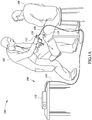
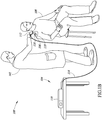
- FIGs 1A and 1B show an environment 100 in which a medical provider 102 operates an interrogation and detection system 104 to ascertain the presence or absence of objects 106 in, or on, a patient 108.
- the interrogation and detection system 104 may include a controller 110, and one or more coil assemblies 314 (see Figure 3D ) coupled to the controller 110 by one or more communication paths, for example coaxial cable 114.
- the antennas may be housed within a hand-held probe 112 that may include one or more antenna coils, for example. While designated as a probe, the blunt instrument is not necessarily intended to explore a wound or to even enter a patient's body. In many applications the hand-held probe will remain on the exterior outside of the patient's body (e.g. , proximate a joint such as a knee, ankle, shoulder, hip, or neck). In some applications, for example labor and delivery (L&D), the patient may not have a wound.
- L&D labor and delivery
- the object 106 may take a variety of forms, for example instruments, accessories and/or disposable objects useful in performing surgical procedures.
- the object 106 may take the form of scalpels, scissors, forceps, hemostats, and/or clamps.
- the objects 106 may take the form of surgical sponges, gauze and/or padding.
- the object 106 is tagged, carrying, attached or otherwise coupled to a transponder 116. Implementations of the interrogation and detection system 104 disclosed herein are particularly suited to operate with transponders 116 which are not accurately tuned to a chosen or selected resonant frequency. Consequently, the transponders 116 do not require high manufacturing tolerances or expensive materials, and thus may be inexpensive to manufacture.
- the medical provider 102 may position the probe 112 proximate the patient 108 in a fixed or static position to detect the presence or absence of the transponder 116 and hence an object 106.
- the medical provider 102 may in some implementations dynamically move the probe 112 along and/or across the body of the patient 108 or may move the probe near other areas, such as a near a trash can or drape bag in a surgery room.
- the probe 112 may be sized to fit at least partially around a knee 118 of the patient 108 to detect the presence or absence of the transponder 116 and hence the object 106.
- the probe 112 may be sized to fit at least partially around a shoulder 119 of the patient to detect the presence or absence of the transponder 116 and hence the object 106.
- the probe 112 may be sized and shaped to fit at least partially around various joints of the patient 108.
- FIG. 2A shows a transponder 116a according to one illustrated implementation.
- the transponder 116a includes a miniature ferrite rod 230 with a conductive coil 232 wrapped about an exterior surface thereof to form an inductor (L), and a capacitor (C) 234 coupled to the conductive coil 232 to form a series LC circuit.
- the conductive coil 232 may, for example, take the form of a spiral wound conductive wire with an electrically insulative sheath or sleeve.
- the transponder 116a may include an encapsulant 236 that encapsulates the ferrite rod 230, conductive coil 232, and capacitor 234.
- the encapsulant 236 may be a bio-inert plastic that protects the ferrite rod 230, conductive coil 232 and/or capacitor 234 from pressure and/or from fluids, for example bodily fluids.
- the ferrite rod 230 may include a passage 238 sized to receive a physical coupler, for example a bonding tie or string 240.
- the bonding tie or string 240 may take the form of an elastomeric x-ray opaque flexible elongated member, that may be used to attach the transponder 116a to various types of objects 106, for example surgical sponges.
- the transponder 116a may have a length of about 8 millimeters and a diameter of about 2 millimeters. Employing such small dimensions ensures that the transponder 116a does not impede deformation of objects 106 such as sponges.
- the transponder 116a may include an optional diode (not shown), to protect against over-voltage occurrences caused by other electronic instruments.
- FIG. 2B shows a transponder 116b, according to another illustrated implementation.
- the transponder 116b includes a single loop of conductive material 242, for example a loop of conductive wire forming an inductor (L), coupled in series to a capacitor 244 (C) to form an LC series circuit.
- the loop of conductive material 242 and capacitor 244 may be encapsulated in an elastomeric coating or sleeve 246.
- the dimensions of the transponder 116b may be similar to the dimensions of the transponder 116a. In some implementations, the dimensions of the transponder 116b are greater than the dimensions of the transponder 116a.
- the transponder 116b is highly flexible, and thus may provide its own thread-like or string-like attachment to various types of objects 106.
- FIG. 2C shows a transponder 116c according to a further implementation.
- the transponder 116c includes a dumbbell-shaped ferrite rod 248 having broad end portions 248a, 248b, and a narrow intermediate portion 248c which is wrapped by a conductive coil 250.
- the broad end portions 248a, 248b contain the conductive coils 250.
- Such a design may provide stronger and/or more reliable signal emission than transponders 116a, 116b fashioned with cylindrical ferrite rods.
- the transponder 116c may optionally include an encapsulant 252. Further details regarding the transponder 116c may be found in U.S. Provisional Patent Application No. 60/811,376 filed June 6, 2006 , published as US2007285249 A1 .
- the transponder 116c may be formed as a fusiform-shaped object, with truncated ends.
- the fusiform shape maybe advantageous over cylindrical shaped transponders 116a, 116b in reducing the likelihood of close parallel alignment of the transponders 116a, 116b, which may produce transponder-to-transponder interaction and interference.
- FIGS 2D-2G show a transponder 116d according to yet a further implementation.
- the transponder 116d includes a ferrite core 253, inductor (L) 254, and capacitor (C) 255 electrically coupled to the inductor 254 to form an LC series circuit.
- the transponder 116d also includes a capsule 256 with a cavity 257 open at one end to receive the ferrite core 253, inductor 254 and capacitor 255, as well as a lid 258 to close the open end of the capsule 256.
- the drum may have a pair of larger diameter end portions 253a, 253b, with a smaller diameter intermediate portion 253c therebetween.
- the inductor 254 may take the form of magnet wire wrapped around the intermediate portion 253c of the ferrite core 253.
- the magnet wire may, for example, have a dimension of approximately 41 American Wire Gauge (AWG), although some implementations may employ wires or conductors of larger or small gauges.
- Suitable inductors 254 may be commercially available from ELEKTISOLA under part no. PN-155 or from ROSEN under part no. 2UEW-F.
- the inductor may, for example, include approximately 432 turns, over approximately 6.5 layers, although some implementations may include a greater or lesser number of turns and/or layers.
- the transponder 116d may include tape and/or epoxy enveloping the inductor 254. Suitable tape may be commercially available from 3M under part nos. 1298, 1350-1 or PLEO 1P801, while suitable epoxy may be commercially available from LOCKTITE under part no. 3211.
- the capacitor 255 may, for example, take the form of a ceramic capacitor.
- the capacitor 255 may, for example, have a capacitance of 470PF, 100V, with a Quality factor of Q > 2200 @ 1MHz.
- Suitable capacitors 255 may be commercially available from SANJV DIELECTRIC under part no. 0805NPO471J101 or from FENG HUA under part no. 0805CG471J101NT.
- the capsule 256 and lid 258 may, for example, be formed of a polypropylene. Suitable capsules 256 and lids 258 may be commercially available from WEITHE ELECTRON (HK) COMPANY, under part specification CASE 4.3x12.6. The combination of the capsule 256 and lid 258 may, for example, have a length of approximately 12.8 mm and a diameter of 4.4 mm. Circuit bonds may, for example, employ UNITED RESINS CORP. part no. 63001500 CIRCUIT BOND LV, while solder may take the form of a lead free 96.5% Ag / 3% Sn / 0.5 Cu solder.
- the transponders 116 may be attached to hemostats, scissors, certain forms of forceps, and the like. In some implementations, the transponders 116 may be coupled to the object 106 byway of a clamp or holder. In some implementations, the transponders 116 may be retained within a cavity of the holder. In some implementations, the holder may be fashioned of a durable deformable material, such as surgical grade polymer, which may be deformed to clamp securely onto the finger or thumbhole of an instrument. In other implementations, the transponders 116 may be attached to objects 106 by way of pouches fashioned of sheet material ( e.g. , surgical fabric) surrounding the transponder 116. The transponder 116 is retained within the pouch, and in some implementations the pouch may be sewn or otherwise sealed. Sealing may be done with adhesive, hot glue, clamping, grommeting, or the like.
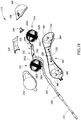
- Figures 3A-3D , 17 , 18 , 19A-19B , 20, 21 , 22A and 22B show various views of the probe 112 also shown in Figures 1A-1B , according to one illustrated implementation.
- the probe 112 includes a bottom housing 302 having a distal or front end portion 304 and a proximal or rear end portion 306 spaced apart from the front end portion.
- the probe 112 also includes a front top housing 308 that mates to the front end portion 304 of the bottom housing 302 to form a substantially spherical front body portion 310 that defines a cavity 312 that accommodates a front coil assembly 314 therein.
- the probe 112 also includes a rear top housing 316 that mates to the rear end portion 306 of the bottom housing 302 to form a substantially spherical rear body portion 318 that defines a cavity 320 that accommodates a rear coil assembly 322 therein.
- the probe 112 may also include a top middle housing 324 that mates with a middle portion 326 of the bottom housing 302 between the front end portion 304 and the rear end portion 306 of the bottom housing to form a cavity 328 that accommodates a circuit board 330 electrically coupled to the front coil assembly 314 and the rear coil assembly 322.
- the circuit board 330 may be coupled to the middle portion 326 of the bottom housing 302 via one or more fasteners ( e.g. , screws 332).
- the front and rear top housings 308, 316 and the top middle housing 324 may be fixedly coupled to the bottom housing 302 during manufacture by any suitable process (e.g., an adhesive such as LOCTITE 414®, RF welding, friction fit, snap fit, tabs and lips, pins and holes, detents, etc.).
- the middle portions 324, 326 of the probe 112 may form a handle portion 334 extending between the spherical body portions 310 and 318.
- the handle portion 334 may be sized and dimensioned to be gripped by the hand of the medical provider 102 ( Figures 1A-1B ).
- the handle portion 334 may include an overmolded gripping surface.
- the overmolded gripping surface may be a material that provides a relatively high degree of tact and/or may be textured to facilitate non-slip gripping.
- the handle portion 334 may be shaped similar to that of a conventional phone, which is ergonomically desirable for the medical provider 102. Further, as shown best in Figure 3C , the handle portion 334 is curved or bent between the first body portion 310 and the second body portion 318 to allow the first body portion and the second body portion to at least partially surround a joint 121 during use.
- the handle portion 334 and the body portions 310 and 318 together form an inverted trough or "U-shape" that forms a joint receiving portion 335 which receives the joint 121 during use.
- the body portions 310 and 318 may both be positioned simultaneously against sides of the joint 121 to increase the likelihood that a transponder 116 will be detected.
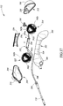
- front and rear body portions 310 and 318 may define respective front and rear cavities 312 and 320 ( Figure 17 ) sized and dimensioned to receive the front and rear coil assemblies 314 and 322, respectively.
- Figures 3D , 19A-19B and 22A-22B show various views of portions of the front coil assembly 314.
- the rear coil assembly 322 may be substantially identical to the front coil assembly 314, so the discussion below regarding the front coil assembly also applies to the rear coil assembly.
- the front coil assembly 314 may, for example, take the form of an air-coil formed of coils of conductive material, for example, electrical wire.
- the front coil assembly 314 acts as an inductor that facilitates magnetic inductive coupling with one or more coils of a transponder 116.
- the front coil assembly 314 may include three antenna coils: a radially inner coil 338a, a radially middle coil 338b, and a radially outer coil 338c mutually orthogonal to each other.
- the antenna coils 338a, 338b, and 338c are wound around outer surfaces 340a, 340b, 340c, respectively ( Figure 19A ), of respective coil form channels 342a, 342b, and 342c of a coil form or bobbin 344.
- the coil form 344 maybe a flexible printed circuit board (e.g., relatively few laminations of FR4).
- the coil form 344 may include strain relief structures or features such as notches, or cutouts laterally across the width of the printed circuit board and/or extending into the surface or along the edges of the printed circuit board.
- the electrical wires 346a, 346b, and 346c, of the respective coils 338a, 338b, and 338c may be coupled to the printed circuit board 330, which may in turn be coupled to wires 348 of a coupling member 350, which may be positioned in the cavity 320 in the rear body portion 318 to provide a connector to communicatively couple to an end of the coaxial cable 114 to the antenna coils of the first and second coil assemblies 314 and 322.
- the coupling member 350 may take the form of a standard coaxial connector, for example. Some implementations may employ other types of wired and/or wireless communications pathways between the controller 110 and the coil assemblies 314 and 322, and thus may employ other types of coupling members or connectors.
- the probe 112 may include one or more user interface devices, for example one or more visual indicators 352 ( Figure 3A ) to provide visual indications to the medical provider 102.
- Such may, for example, take the form of one or more light emitting diodes 354 ( Figure 17 ), which may provide one or more different colors.
- Such user interface devices may additionally or alternatively include a speaker or other transducer (e.g ., piezoelectric transducer, electric motor), operable to provide a sound or other sensory indication, for example a tactile sensation ( e.g ., vibration).
- a tactile sensation e.g ., vibration
- Such user interface devices may be operable to provide sensory feedback to the medical provider 102 indicative of an operating condition of the interrogation and detection system 104.
- Locating user interface devices on the probe 112 may be advantageous since the medical provider 102 will typically focus their attention on the probe 112 while scanning the patient 108.
- the printed circuit board 330 includes the light emitting diode 354 ( Figure 17 ) coupled thereto.
- a light pipe 356 may be positioned within an aperture 358 of the front top housing 308.
- the light pipe 356 is light transmissive such that light from the light emitting diode 354 may pass through the light pipe where it is visible by a user.
- the light emitting diode 354 may be used to provide a visual indication to a user of the probe 112, such as status information or operational information.
- the generally spherical coil form 344 includes the three mutually orthogonal coil form channels 342a, 342b, and 342c each having a respective outer surface 340a, 340b, and 340c for supporting a respective one of the coils 338a, 338b, and 338c.
- the first coil form channel 342a is oriented in an XY plane
- the second coil form channel 342b is oriented in an XZ plane
- the third coil form channel 342c is oriented in a YZ plane.
- the three coil form channels 342a, 342b, and 342c may intersect each other or may be nested.
- Each of the three coil form channels 342a, 342b, and 342c defines its respective outer coil support surface 340a, 340b, and 340c.
- Each outer coil support surface 340a, 340b, 340c is substantially cylindrically shaped with a curved surface. More specifically, in the illustrated implementation each outer coil support surface 340a, 340b, and 340c is shaped as a spherical zone of a virtual sphere, the spherical zone having a width W ( Figure 19B ) and being centered on a great circle of the virtual sphere.
- a great circle of a sphere is the intersection of the sphere and a plane which passes through the center point of the sphere.
- a spherical zone is the surface of a spherical segment, which is a solid defined by cutting a sphere with a pair of parallel planes.
- the parallel planes are also parallel to a great circle of the virtual sphere and spaced apart on each side of the great circle by an equal distance ( i.e. , W/2), such that the spherical segment is centered on the great circle.
- each of the outer coil support surfaces have a circumference or length L that is defined by a body of revolution about a respective primary axis and a width W that is curved about a respective secondary axis orthogonal to the primary axes.
- the length L of the outer coil support surface 340a is defined by a revolution about the Z axis ( Figure 22A ) and the width W is curved about the X axis ( Figure 22B ).
- the length L of the outer coil support surface 340b is defined by a revolution about the Y axis and the width W is curved about the Z axis.
- the length L of the outer coil support surface 340c is defined by a revolution about the X axis and the width W is curved about the Z axis.
- each of the outer coil support surfaces 340a-340c are equal to each other.
- the length L of the outer coil surface 340a at its center may be defined by a circle in the XY plane having a curvature radius R L-340a ( Figure 22A ).
- the width W of the outer coil surface 340a has a radius of curvature of R W-340a ( Figure 22B ), which is equal to the radius R L-340a of the length L.
- eight apertures 360 shaped as spherical triangles may be defined by the intersection of the coil form channels 342a, 342b, and 342c.
- the size of the eight apertures 360 is dependent on the width W of the coil form channels 342a, 342b, and 342c. That is, the wider the width W of coil form channels 342a, 342b, and 342c, the smaller the eight apertures 360.
- the apertures 360 are not present and the coil form 344, such that the coil form is substantially shaped as a sphere without apertures therein.
- the interior of the coil form 344 may be hollow, whereas in other implementations one or more materials may be present within the interior of the coil form.
- an interior surface 362 of the front top housing 308 may include an alignment rib 364 shaped and sized to be inserted into one of the spherical triangle-shaped apertures 360 of the coil form 344.
- the front end portion 304 of the bottom housing 302 may also include an alignment rib 366 on an interior surface 368 thereof.
- the alignment ribs 364 and 366 on the respective interior surfaces 362 and 368 of the housings 308 and 302 align the coil form 344 relative to the housings during manufacturing and fix the position of the coil form with respect to the assembled housing.
- the coil form 344 may be secured to the front end portion 304 of the bottom housing 302 and the front top housing 308 by a suitable adhesive (e.g., PC-11 A and PC-11 B two-part epoxy).
- the rear coil assembly 322 may be secured to the rear end portion 306 of the bottom housing 302 and the rear top housing 316 in a similar manner.
- the first coil 338a is wound around the outer coil support surface 340a of the first coil support channel 342a to form a first antenna element arranged in the XY plane so as to transmit and receive signals primarily in the orthogonal z-axis direction.
- the second coil 338b is wound around the outer coil support surface 340b of the second coil support channel 342b over the first coil 338a to form a second antenna element in the XZ plane so as to transmit and receive signals primarily in the orthogonal y-axis direction.
- the third coil 338c is wound around the outer coil support surface 340c of the third coil support channel 342c over the first coil 338a and over the second coil 338b to form a third antenna element in the YZ plane so as to transmit and receive signals primarily in the orthogonal x-axis direction.
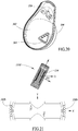
- FIG. 21 shows a sectional view of the second coil 338b disposed in the XZ plane and configured to transmit and receive signals primarily in the orthogonal y-axis direction, and a sectional view of the transponder 116d positioned proximate to the second coil.
- the efficiency of the coupling between the second coil 338b and the inductor or coil 254 of the transponder 116d is proportional to the presentation angle of the two coils relative to each other.
- the ability to detect a transponder is significantly improved.
- the angle ⁇ of rotation of the transponder coil 254 will always be less than 45 degrees with respect to at least one of the orthogonal coils 338a-338c.
- the use of three orthogonal coils 338a-338c ensures that the magnetic coupling between the transponder coil 254 and at least one of the coils 338a-338c of the probe 112 will always be at least 71% of the maximum coupling orientation. Accordingly, given the same transmit energy, transponders 116 may be detected at a greater distance using the two sets of three orthogonal coils 338a-338c as compared to using a single planar coil. Additionally or alternatively, the probe 112 may transmit signals at lower energy levels to achieve a similar read range as a single planar coil transmitting at a higher energy level.
- the respective second support channels 342b of the first coil assembly 314 and the second coil assembly 316 are oriented to be coplanar in an XZ plane to transmit and receive signals primarily in the orthogonal y-axis direction.
- the respective first support channels 342a of the first coil assembly 314 and the second coil assembly 316 are oriented to be parallel and non-coplanar in an XY plane to transmit and receive signals primarily in the orthogonal z-axis direction.
- the respective third support channels 342c of the first coil assembly 314 and the second coil assembly 316 are oriented to be parallel and non-coplanar in a YZ plane to transmit and receive signals primarily in the orthogonal x-axis direction.
- the respective support channels of the first coil assembly 314 and the second coil assembly 322 may aligned differently with respect to each other.
- FIG. 4 shows the controller 110 according to one illustrated implementation.
- the controller 110 includes an input port 420 with an appropriate coupling member, for example a connector to allow an end of the coaxial cable 114 to be communicatively coupled to the controller 110.
- an appropriate coupling member for example a connector to allow an end of the coaxial cable 114 to be communicatively coupled to the controller 110.
- some implementations may employ other communications pathways between the controller 110 and the coil assemblies 314 and 322, hence other types of coupling members or connectors may be employed.
- the controller 110 may also include a power switch (not illustrated in Figure 4 ), for example, positioned on a back or rear of the controller 110.
- the controller 110 may further include a power cord (not shown) to couple the controller 110 to a suitable power supply.
- the power supply may, for example take the form of a standard wall outlet or any other power supply or source.
- the controller 110 may further include one or more user interface devices for providing information to a user.
- the controller 110 may include one or more visual indicators, for instance one or more light emitting diodes (LEDs) 434a-434f and/or liquid crystal displays.
- the controller 110 may include one or more speakers 430 or other transducers operable to produce sound or tactile sensations.
- the controller 110 forms a transmitter and receiver, or transceiver, to transmit interrogation signals and receive responses to those signals, as well as to receive electromagnetic signals which may be indicative of noise.
- Figure 5 shows a control system 500 of the interrogation and detection system 104, according to one illustrated implementation.
- the control system 500 includes a field programmable gate array (FPGA) board 502, analog board 504 and display board 506, communicatively coupled to one another.
- the FPGA board includes an FPGA 508, configuration jumpers 510, RS-232 drivers 512, oscillator 514, random access memory (RAM) 516, flash memory 518, and voltage monitoring (VMON) analog-to-digital converter (ADC) 520.
- the FPGA 508 may take the form of a Xilinx Spartan3 FPGA, which runs FPGA and application software. As explained below, on power up, the FPGA reads the configuration information and application software program from the flash memory 518.
- the configuration jumpers 510 are used to select the application software configuration.
- the RS-232 drivers 512 are used to allow the application software to communicate using serial RS-232 data for factory test and diagnostics.
- the oscillator 514 sets the clock frequency for the operation of the FPGA 508.
- the oscillator 514 may, for example, take the form of 40 MHz oscillator, although other frequencies are possible.
- the RAM 516 is connected to the FPGA 508 and is available for use by the application software.
- the application software uses this memory space for storage of both the executable program and program data.
- the RAM 516 may, for example, have a capacity of 1 MB.
- the flash memory 518 contains both the FPGA configuration data and the binary application program. On power up the FPGA 508 reads the flash memory to configure the FPGA 508 and to copy the application program binary data from the flash memory 518 to the RAM 516.
- the voltage monitor ADC 520 is connected to the FPGA 508 and controlled by the application software to monitor a power supply and regulated voltage forms in controller electronics.
- the analog board 504 includes transmit control circuits 522, capacitor selection circuits 524, probe detection circuit 526, signal ADC 528, audible beeper 430 and self-test signal 532.
- the transmit control circuits 522 on the analog board 504 are controlled by signals from the FPGA 508 to generate a transmit waveform.
- Optional capacitor selection circuits 524 on the analog board 504 are controlled by the signals from the FPGA 508 to tune the drive circuit to match an inductance of the antennas of the coil assemblies 314 and 322.
- the probe detection circuit 526 detects when a probe 112 is connected to the controller 110.
- the output of the probe detection circuit 526 drives a signal denominated as the LOOP_LEVEL_OUT signal, which is an input to the FPGA 508.
- the signal ADC 528 is used as a receiver to sample the signals received at the coil assemblies 314 and 322 from the transponders 116 ( Figures 2A-2C ).
- the signal ADC 528 may, for example, operate at a 1 MHz sample rate and may have 12-bits of resolution.
- the FPGA board 502 generates the timing and control signals for the signal ADC 528, which signals are denominated as ADC_CTRL, CS1, SCLK, and SD0.
- the audible speaker or beeper 430 can be controlled by the FPGA 508 to emit sounds to indicate various states, modes or operating conditions to the medical provider 102 ( Figures 1A-1B ).
- the FPGA 508 can cause the generation of the self-test signal 532 on the analog board 504 at the signal ADC 528. Self-testing may be performed at start up, and/or at other times, for example periodically or in response to the occurrence of certain conditions or exceptions.
- the display board 506 includes user interface elements, for example a number of light emitting diodes (LEDs) 434.
- the FPGA board 502 can control the LEDs 434 on the display board 506.
- the display board 506 also includes a user selectable activation switch, denominated as front panel button 436.
- the front panel button 436 is connected to the display board 506 which allow the FPGA 508 to monitor when the front panel button 436 is activated (e.g., pressed).
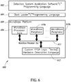
- Figure 6 shows a software configuration 600 of the interrogation and detection system 104, according to one illustrated implementation.
- the software may include application software 602 that is responsible for operating the controller 110 ( Figures 1A-1B and 4 ).
- the application software 602 controls the timing for generating transmit pulses, processes sampled data to detect transponders 116 ( Figures 2A-2C ), and indicates status to the user with the display LED's 434 ( Figure 5 ) on the display board 506 and/or via the audible speaker or beeper 130 on the analog board 504.
- the application software 602 is stored in the flash memory 518 ( Figure 5 ) and transferred into the RAM 516 by a boot loader 604.
- the boot loader 604 is automatically loaded when the FPGA 508 is configured, and starts execution after a processor core 606 is reset.
- the boot loader 604 is responsible for transferring the application software 602 from the flash memory 518 to the external RAM 516.
- the processor platform 608 is configured into the FPGA 508 ( Figure 5 ) on power up from the configuration information stored in the flash memory 518.
- the processor platform 608 implements a custom microprocessor with a processor core 606, peripherals 610a-610n, and custom logic 612.
- the processor core 606 may take the form of a soft processor core supplied by XILINX under the name MICROBLAZE that implements a 32-bit processor including memory cashes and a floating point unit.
- a soft-core processor is one that is implemented by interconnected FPGA logic cells instead of by traditional processor logic.
- the processor core 606 is connected to the internal FPGA peripherals 610a-610n using a 32-bit processor bus 611 called the On-Chip Peripheral Bus.
- the XILINX supplied peripherals for the MICROBLAZE processor core 606 include external memory interfaces, timers, and general purpose I/O.
- the custom logic 612 to create the transmit signals, sample the ADC 128, and accumulate the transponder return signals is designed as a peripheral to the processor core 606.
- the custom logic 612 is the part of the design of the FPGA 508.
- a detection cycle that employs an approach that optimizes signal to noise ratio (SNR) by a receiver portion may be implemented. Such may, for example, advantageously increase range or increase sensitivity at a given range.
- One implementation is optimized based on having an overall detection cycle that performs well for transponders with resonant frequencies from approximately 136 kHz to approximately 154 kHz.
- the application software 602 implements the detection cycle using transmission or interrogation in a frequency band centered around a center channel or frequency.
- the application software 602 sequences through a non-measurement portion (i.e. , gap), and two distinct measurement portions, denominated as a noise detection portion and a signal measurement portion, each detection cycle.
- the detection cycle may, for example, be approximately 275 milliseconds
- the gap portion may be approximately 10 milliseconds
- the noise portion approximately 37 milliseconds
- the signal measurement portion approximately 228 milliseconds.
- the noise detection portion which may, for example be a first measurement portion of each detection cycle, ambient or background noise is measured or sampled, providing a value indicative of a level of ambient or background noise for the particular environment.
- the noise measurements or are taken or captured at a time sufficiently after excitement of the transponders 116 by the interrogation signal emitted by the transmitter such that the transponders 116 are substantially not resonating or responding to any previous excitation by interrogation signals.
- a number N of measurements or samples are taken during the noise detection or first measurement portion.
- responses by transponders 116 are measured or sampled.
- the response measurements or samples are taken with the transmitter transmitting or at a time sufficiently close to excitement of the transponders 116 by the interrogation signal emitted by the transmitter such that the transponders 116 are still substantially resonating or responding to the interrogation signal.
- a number M of measurements or samples are taken during the interrogation or second measurement portion.
- the signal measurement portion may be one contiguous or continuous portion, in some implementations the signal measurement portion may take the form of two or more separate portions or intervals. Each of the portions may employ the same transmit frequency band, for example centered around 145 kHz. Other center channels or frequencies may for example be 136 kHz, 139 kHz, 142 kHz, 145 kHz, 148 kHz, 151 kHz and/or 154 kHz, or any other frequency suitable for exciting the transponder to resonate. Some implementations may employ frequency hopping, for example transmitting a different center channel or frequency for each of a plurality of signal measurement portions of each detection cycle. Such is discussed further in U.S. provisional patent application Serial No. 60/892,208, filed February 28,2007 and U.S. non-provisional application Serial No. 11/743,104, filed May 1,2007 .
- the gap portion may provide time for the response of the transponders 116 to the interrogation signal to decay sufficiently to allow measurement of noise.
- Some implementations may arrange the gap, the noise detection portion and/or the signal measurement portion, or parts thereof, in a different order.
- the time to accumulate the noise sample or value indicative of a noise level may, for example, be approximately 37 milliseconds, and the time to accumulate the transponder signal measurement approximately 228 milliseconds. Along with a gap of approximately 10 milliseconds between the signal and noise portions, the time for a single detection cycle would be approximately 275 milliseconds.
- the transmitter is OFF during the noise measurement portion of each detection cycle to allow the receiver to measure ambient noise, and the signal detection portion is taken with the transmitter transmitting a wideband interrogation signal about the particular center channel or frequency.
- the noise samples collected by the receiver may be accumulated and a highest one or more of multiple samples or measurements over one or more detection cycles selected or used to prevent unwarranted fluctuations.
- the response signals from the transponder 116 may be accumulated and/or averaged or integrated over one detection cycle or over multiple detection cycles.
- the number N of noise measurements or samples and/or the number M of response signal measurements or samples may be selected to achieve a desired ratio of N to M, in order to achieve or maintain a desired signal to noise ratio. For example, obtaining 200 noise measurements or samples and 800 response measurements or samples each detection cycle results in an SNR of approximately 2 ( e.g., the square root of 800 divided by 200). While an SNR as low as 1.1:1 may be sufficient in some implementations, an SNR approaching 2:1 ensures sufficient differentiation to eliminate or reduce the possibility of false positives to an acceptable level for the particular applications envisioned herein. Any known hardware and software accumulators, summers, integrators and/or other hardware or software may be suitable.
- the accumulated or integrated received signal may be matched filtered with both in-phase and quadrature reference signals to determine the signal magnitude.
- the received receive signal is matched filtered with a plurality of reference signals, for example with the seven reference signals, for instance as shown in Table 1 below. Some implementations may employ matched filtering before accumulating or integrating the received signal. TABLE 1 Match Frequency 136 kHz 139 kHz 142 kHz 145 kHz 148 kHz 151 kHz 154 kHz
- the maximum value for the matched filters (e.g. , seven matched filters) with active transmit may be compared with an adjusted detection threshold. If the maximum value is greater than the detection threshold, then a response signal from a transponder 116 may be considered as having been detected, and appropriate action is taken, such as discussed below with reference to Figure 7 .
- the interrogation and detection system may employ a fast Fourier transform approach in lieu of matched filtering.
- the noise filtering processes the measured or sampled noise values for each detection cycle to determine a stable noise floor value.
- the output of the noise filter may, for example, be the maximum of either the current noise measurement or a decayed value of the previous noise floor.
- the output of the noise filter may be an estimate of the current noise floor level after selecting the highest of a plurality ( e.g., 6) of noise measurements or samples.
- the filtered noise floor may advantageously include samples collected, captured or measured both before and after a given signal sample is collected, captured or measured. Thus, for any sample of a given detection cycle the noise floor may include noise samples from the given detection cycle, as well as a next successive detection cycle.
- the filtered noise floor may additionally, or alternatively, include noise samples from one or more successively preceding detection cycles, as well as one or more successfully succeeding detection cycles.
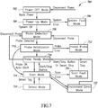
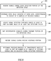
- Figure 7 shows a method 700 of operating the interrogation and detection system 104 according to one illustrated implementation.
- the interrogation and detection system 104 enters a Power OFF mode at 702.
- the Power OFF mode 702 may be entered when the controller 110 ( Figures 1A-1B and 4 ) is unplugged or when the power switch on the controller 110 is turned OFF.
- the Power LED 434a and other front panel LEDs 434 will be turned OFF (non-emitting).
- the software 700 is inoperative in the Power OFF mode 702.
- the interrogation and detection system 104 enters a Power-Up mode 704.
- the Power UP mode 704 may, for example, in response to the application of power to the controller 110 and turning ON the switch on the back of the controller.
- a Power LED 434a may be turned ON or illuminated, and may remain ON or illuminated as long as the power is applied and the switch is in the ON state.
- the software 700 will perform software initialization, built in tests, and an audio/visual test.
- the software 700 progresses to a System Fault Mode 706. If no faults are detected, the software 700 may turn a System Ready LED green, and enter a Probe Detection Mode 708.
- the software 700 may cause an indication of the detection of a system fault by blinking a System Ready LED 434b yellow, and/or issuing a sequence of rapid beeps or other sounds.
- the corrective action for the System Fault Mode 706 is to cycle power to reinitiate the Power Up mode 704. Continued failure indicates a failed controller 110.
- the software 700 checks for a probe 112 connected to the controller 110.
- the Probe Detection Mode 708 may be indicated by turning the System Ready LED 434b green and turning the Probe Ready LED 434c OFF. If no probe 112 is detected, the software 700 remains in the Probe Detection Mode. If a probe 112 is detected, the software 700 progresses to the Probe Initialization Mode 710.
- the software 700 may turn the Probe Ready LED 434c yellow and check for the presence of a fuse in the probe 112. If a fuse is found, the software 700 may attempt to blow the fuse and verify that the fuse was correctly blown. After the fuse is blown the software 700 may verify that probe 112 is operating within tolerances. The software 700 may indicate that the probe 112 is ready by turning the Probe Ready LED 434c green. The software 700 may also start a timer which will allow the probe 112 to be disconnected and reconnected to the controller for a period to time ( e.g., 5 hours) after the fuse is blown.
- a timer which will allow the probe 112 to be disconnected and reconnected to the controller for a period to time ( e.g., 5 hours) after the fuse is blown.
- the controller 110 may determine the adjustments or fine tuning to be made about the center frequencies or channels during Probe Initialization Mode 710.
- the controller 110 may determine the particular frequency in each of the frequency bands that elicits the response with the highest voltage.
- the controller may determine such by varying the capacitance of the LC circuit using the switched capacitors C33-C36 during the Probe Initialization Mode 710.
- the particular combination of switched capacitors C33-C36 which achieved the response with the highest voltage may then be automatically employed during a Scan Mode 714 (discussed below) to adjust or fine tune about the center frequency or channel in each broad band of transmission.
- Other approaches to determining the fine tuning may be employed.
- the software 700 If the software 700 does not successfully complete the Probe Initialization Mode 710, the software 700 enters an Invalid Probe Mode 712. If the software 700 successfully completes the Probe Initialization Mode 710, the software 700 progresses to the Scan Mode 714 to automatically start scanning.
- the software 700 may blink the Probe Ready LED 434c yellow and issues a slow beep pattern.
- the Invalid Probe Mode may be entered in response to any of the following conditions: The probe 112 connected to the controller 110 is out of tolerance.
- the controller 110 is unable to blow the fuse in the probe 112.
- the probe 112 does not have a fuse and more than the set time period has past ( e.g., 5 hours) since a fuse was blown.
- the probe 112 does not have a fuse and the controller 110 has been restarted.
- the probe 112 has been connected to the controller for more than the set time period (e.g., 5 hours).
- the probe 112 is detuned due to close proximity to metal.
- the corrective action for the Invalid Probe Mode 712 is to remove the invalid probe 112 and attach a new probe 112 to the controller 110 that contains a fuse or to reconnect the probe 112 while holding it in the air at least 2 feet away from large metallic objects.
- the software 700 enters the Scan Mode 714 when the probe 112 is ready and the operator presses a Start/Stop button.
- the software 700 may issue a short three beep pattern via the speaker or beeper 130 when entering the Scan Mode 714 to identify the entry to the user.
- the software 700 may continuously or periodically perform the following functions.
- the software 700 may issue a short three beep pattern and return to the Probe Ready Mode 716.
- the software 700 may turn ON an amber DETECT LEDs 434d and/or provide an audible alarm.
- the alarm may, for example, beep a continuous solid tone as long as the transponder is detected, with a minimum of beep duration of, for instance 0.5 second.
- the software 700 detects the probe 112 is disconnected while in the Scan Mode 714, the software 700 enters the Scan Fault Mode 720.
- the software 700 may issue a sequence of rapid beeps and blink ON and OFF the amber DETECT LEDs 434d.
- the Scan Fault Mode 720 can be cleared by pushing the Start/Stop button. The software 700 will automatically clear the Scan Fault Mode 720 after 10 beeps.
- the software 700 While in the Scan Mode 714, if excess noise or loss of transmit signal is detected, the software 700 will progress to the Environment Error Mode 722. In the Environment Error Mode 722, the software 700 may issue or produce an appropriate indication. For example, the software 700 may cause the production of a sequence of slow beeps and the blinking ON and OFF the green circle LEDs 434e. The corrective action for the Environment Error Mode 722 is to reposition the probe 112 away from large metal objects or sources of electrical interference. The software 700 will automatically stop the scan if the environment error condition lasts for more than a set time or number of beeps ( e.g., 5 beeps).
- a set time or number of beeps e.g., 5 beeps
- Figure 8 shows a method 800 of operating an interrogation and detection system, according to one illustrated implementation.
- the method 800 may be implemented by any of the interrogation and detection system implementations discussed above.
- the interrogation and detection system performs a number of acts 802-812.
- the interrogation and detection system receives electromagnetic signals, for example unmodulated electromagnetic signals, during a noise detection portion of the detection cycle.
- electromagnetic signals for example unmodulated electromagnetic signals
- RFID radio frequency identification
- the interrogation and detection system determines a noise value indicative of a noise level that corresponds to a highest one of a number N of samples or measurements of the unmodulated electromagnetic signals received during the noise detection portion of the detection cycle, where the number N is greater than one.
- the interrogation and detection system adjusts a signal detection threshold based at least in part on the determined noise value of at least one of the detection cycles.
- the interrogation and detection system emits at least one electromagnetic interrogation signal during a transmit portion of the detection cycle.
- the interrogation and detection system receives unmodulated electromagnetic signals during a receive response portion of the detection cycle that follows the transmit portion of the detection cycle.
- the interrogation and detection system determines the presence or absence of a transponder based at least in part on a number M of samples or measurements of the unmodulated electromagnetic signals received during the detection cycle and the adjusted signal detection threshold, where the number M is greater than one.
- a ratio of N:M may be at least equal to 4.
- N may be equal to about 200 and M may be equal to about 800, for example.
- the interrogation and detection system may determine a noise value indicative of a noise level based at least in part on the unmodulated electromagnetic signals received during the noise detection portion of the detection cycle by setting the noise value based on the highest one of six samples or measurements of the unmodulated electromagnetic signal received during the noise detection portion of the detection cycle.
- the interrogation and detection system may adjust the signal detection threshold by adjusting the signal detection threshold based at least in part on a first number of determined noise values indicative of a noise level during at least one noise detection portion that occurred before the receive response portion of a first one of the detection cycles and a second number of determined noise values indicative of a noise level during at least one noise detection portion that occurred after the receive response portion of the first one of the detection cycles.
- the interrogation and detection system may adjust the signal detection threshold based at least in part on the determined noise value of at least one of the detection cycles by adjusting the signal detection threshold to be approximately twice an average of at least one of the first and the second number of determined noise values.
- the interrogation and detection system may adjust the signal detection threshold based at least in part on the determined noise value of at least one of the detection cycles by adjusting the signal detection threshold to be approximately twice a greatest one of at least one of the first and the second number of determined noise values.
- the interrogation and detection system may determine the presence or absence of a transponder by comparing a maximum value of a plurality of matched filter outputs with the adjusted signal threshold.
- the interrogation and detection system may adjust the signal detection threshold based at least in part on the determined noise value of at least one of the detection cycles by adjusting the signal detection threshold to be approximately twice the determined noise value.
- the interrogation and detection system may adjust the signal detection threshold based at least in part on the determined noise value of at least one of the detection cycles includes adjusting the signal detection threshold to be the larger of approximately twice the determined noise value or a defined threshold value.
- the defined threshold value may for example be approximately 0.5 mV.
- the interrogation and detection system determines if an output of at least one matched filter during the noise detection portion of the detection cycle exceeds a noise fault threshold indicative of a noise fault.
- the interrogation and detection system determines if the output of the at least one matched filter during the noise detection portion of the detection cycle exceeds the noise fault threshold for a defined period of time.
- the interrogation and detection system may terminate the detection cycle in response to the output of the at least one matched filter exceeding the noise fault threshold for the defined period of time.
- the interrogation and detection system may convert the received signal(s) from the time domain to the frequency domain spectrum.
- the interrogation and detection system may, for example, perform a Fourier transform, for instance a fast Fourier transform such as a 256 point fast Fourier transform. Suitable algorithms and/or sets of software code for performing such are available or can be written.
- the interrogation and detection system may search the frequency domain spectrum to determine the object with the strongest resonance in a defined frequency band. For example, the interrogation and detection system may search the frequency domain spectrum from about 120 kHz to about 175 kHz.
- An amplitude of the resonant object may be computed as the sum of the resonant power plus and minus 2 fast Fourier transform bins from the peak resonance frequency. This approach may provide a more accurate measurement of power than simply using the peak value.
- the frequency of the resonant object may be computed using an interpolation approach. This approach may provide a more accurate determination of resonant frequency than simply using the fast Fourier bin number.
- the interrogation and detection system may determine the presence or absence of a transponder based at least in part on a frequency of the unmodulated electromagnetic signals received during the detection cycle being within a defined frequency range.
- the defined frequency range may extend from about 137 kHz to about 160 kHz, for example.
- the interrogation and detection system may determine a Q value (i.e. , Quality factor) of the resonant object from a signal decay slope for the received unmodulated electromagnetic signal(s) returned by the resonant object.
- the interrogation and detection system may, for example, use multiple windows, for instance five (5) window positions may provide suitable results.
- the interrogation and detection system may determine the presence or absence of a transponder based at least in part on a Q value of the unmodulated electromagnetic signal(s) received during the detection cycle.
- the interrogation and detection system may preferably employ the Q value determination in conjunction with determination based on the frequency and on the determination based on the adjusted signal detection threshold.
- the interrogation and detection system determines the presence or absence of a transponder is based at least in part on a Q value of the unmodulated electromagnetic signals received during the detection cycle being at least equal to a threshold Q value.
- the threshold Q value may be 35, for example.
- the interrogation and detection system may preferably employ the Q value determination in conjunction with determination based on the frequency and on the determination based on the adjusted signal detection threshold.
- tag detection may advantageously be based on the received unmodulated electromagnetic signal(s) satisfying all three conditions: 1) measured amplitude is above a threshold, which may be an adjustable threshold, 2) measured frequency is between a lower limit and an upper limit, and 3) measured Q value is above a minimum Q threshold. Interference, for example from RFID tags or EKG cables, are rejected when any of the following three conditions are satisfied: a) measured frequency is below the lower frequency limit, b) measured frequency is above the upper frequency limit, or c) measured Q value is below the threshold Q value.
- a threshold which may be an adjustable threshold
- measured frequency is between a lower limit and an upper limit
- measured Q value is above a minimum Q threshold.
- Figure 9 shows a graph 900 of a simulated transponder response signal 902 and a noise signal 904.
- the inexpensive transponders usable with implementations disclosed herein typically have a relatively large variation in the frequency of signals they emit, making it difficult to accurately detect the signals returned by the transponders. This may be particularly difficult in some environments which are noisy with respect to the particular resonant frequencies of the transponders. For example, operating rooms may have one or more electronic medical devices that emit RF noise that is harmonically synchronous with the response signals received from the transponders.
- the transponder response signal 902 may, for example, be a nominal periodic signal centered around a particular frequency (e.g. , 136 kHz, 145 kHz, 154 kHz, etc.).
- the noise signal 904 may be emitted from an electronic medical device located proximate to the interrogation and detection system 104 ( Figures 1A-1B ), for example. In this illustration, the amplitude of the noise signal 904 is much greater than the amplitude of the transponder response signal 902. As shown, at a point 906 in time the noise signal 904 is at a peak and the transponder response signal 902 is near its zero crossing.
- the noise signal 904 would mask the transponder response signal 902. Conversely, at points 908 and 910, the noise signal 904 is at or close to its zero crossing while the transponder response signal 902 is near its peak. If the interrogation and detection system 104 can sample the simulated response signal 902 at times when the noise signal 904 is at its zero crossing or at a low amplitude, it is possible for the interrogation and detection system to detect a transponder through the noise signal 904 (or "noise floor") that is many times greater than the transponder response signal 902.
- the scanning process for each antenna or coil is broken down into N SS subsample scan cycles for each transmit frequency.
- Each of the subsample scan cycles includes one or more interrogation cycles.
- each of the interrogation cycles in a particular one of the N SS subsample scan cycles is shifted forward in time a fraction of the period (T) of a nominal expected transponder response signal 902 to provide N SS opportunities to avoid harmonic noise being synchronous in time with the desired transponder response signal.
- FIG 10 illustrates timing for a single interrogation cycle 1010 in an implementation that utilizes the aforementioned subsample scan cycles, according to one illustrated implementation.
- Each of the N SS subsample scan cycles may include one or more interrogation cycles 1010, as discussed below.
- the custom logic in the FPGA 508 ( Figure 5 ) generates the timing and control signals for each interrogation cycle 1010.
- the logic of the FPGA 508 drives transistor control lines to generate the transmit signal.
- the FPGA logic controls the frequency of the transmit signal.
- the transmit portion 1010a has a duration of 200 microseconds ( ⁇ s), for example.
- a dump portion 1010b of the interrogation cycle 1010 the logic of the FPGA 508 drives a gate of a dump TRIAC to quickly drain the transmit energy from the antenna to allow detection of the response signal from the transponder 116, if any.
- the dump portion 1010b has a duration of 10 ⁇ s, for example.
- a recovery portion 1010c of the interrogation cycle 1010 allows receive filters and amplifiers to recover from the transmitted signal before detecting the response signal from the transponder 116, if any.
- the recovery portion 1010c may have a duration of 100 ⁇ s, for example.
- the FPGA 508 controls the signal ADC 128 to sample the response signal from the transponder 116, if any.
- the signal ADC 128 may, for example, sample at a 1 MHz sample rate (i.e., 1 sample per ⁇ s) with a 12-bit resolution.
- the receive response portion 1010d has a duration of 512 ⁇ s, such that the signal ADC 128 obtains 512 measurements at the 1 MHz sample rate during the receive response portion 1010d.
- a skip portion 1010e of the interrogation cycle 1010 may be provided during which time measurements from the signal ADC 128 are skipped or ignored. In some implementations, the skip portion 1010e has a duration of 40 ⁇ s.
- the timing of the receive response portion 1010d may be such that the transponder response signal is synchronous to the transmit time.
- a subsample scan cycle delay period 1010f of the interrogation cycle 1010 has a unique duration for interrogation cycles associated with a particular one of the N SS subsample scan cycles. Interrogation cycles associated with different ones of the N SS subsample scan cycles may have subsample scan cycle delay periods 1010f having differing durations.
- the subsample scan cycle delay period 1010f associated with respective ones of the N SS subsample scan cycles may be approximately a fraction of the period (T) of the expected transponder response signal 902 ( Figure 9 ).
- the subsample scan cycle delay periods 1010f for interrogation cycles associated with subsample scan cycles 1 to N SS may be approximately:
- the period (T) of the expected transponder response signal is divided into N SS start times, with each of the N SS subsample scan cycles being associated with a different one of the start times.
- FIG 11A is a timing diagram 1100 illustrating an overall instrument scan cycle 1102, according to one illustrated implementation.
- the instrument scan cycle 1102 may be implemented by the interrogation and detection system 104 to scan for one or more resonant transponders.
- the instrument scan cycle 1102 may have a duration between a start time and a stop time that is less than about 20 seconds ( e.g. , two seconds, five seconds, 10 seconds, 15 seconds, etc.) so that the user operating the interrogation and detection system 104 does not need to wait an extended period of time to perform a scan operation.
- the instrument scan cycle 1102 may be executed one or more times during the Scan Mode of the interrogation and detection system 104.
- each instrument scan cycle 1102 may include one or more coil scan cycles, which may include one or more frequency specific sample cycles, which may include one or more subsample scan cycles, which may include one or more interrogation cycles.
- the instrument scan cycle 1102 includes a number N COILS of coil scan cycles 1104, one coil scan cycle for each of N COILS present in the interrogation and detection system 104.
- FIG 11B is a timing diagram 1106 illustrating a cycle for one of the coil scan cycles 1104 shown in Figure 11A , according to one illustrated implementation.
- the coil scan cycle 1104 includes a number N FREQ of frequency specific sample cycles 1108, one for each transmit frequency to be used by the interrogation and detection system 104.
- the number N FREQ of frequency specific sample cycles 1108 may be any suitable value, such as one, two, five, eight, etc.
- the interrogation and detection system 104 may transmit interrogation signals at 139 kHz, 145 kHz, and 154 kHz during frequency specific sample cycle 1, frequency specific sample cycle 2, and frequency specific sample cycle 3, respectively.
- the interrogation and detection system 104 may transmit at a single frequency, such that only a single frequency specific sample cycle 1108 is performed during each coil scan cycle 1104.
- FIG. 11C is a timing diagram 1110 illustrating a cycle for one of the frequency specific sample cycle 1108, according to one illustrated implementation.
- the frequency specific sample cycle 1108 includes a number N SS of subsample scan cycles 1112, one for each subsample to be collected by the interrogation and detection system 104.
- a subsample may refer to measurements obtained during a subsample scan cycle.
- the number N SS of subsample scan cycles 1112 in each frequency specific sample cycle may be any suitable value, such as two, five, 10, 15, etc.
- each of the N SS subsample scan cycles has a unique subsample scan cycle delay period associated therewith.
- the subsample scan cycle delay periods for each of the N SS subsample scan cycles are applied during respective interrogation cycles associated with the respective subsample scan cycles.
- Figure 11D is a timing diagram 1114 illustrating one cycle of one of the subsample scan cycles 1112, according to one illustrated implementation.
- the subsample scan cycle 1112 includes a number N I of interrogation cycles 1010 ( Figure 10 ). As discussed below with reference to the example shown in Figure 12 , each of the N I interrogation cycles 1010 has a subsample scan cycle delay period 1010f associated with one of the particular subsample scan cycles 1112. In other words, interrogation cycles 1 to N I for one of the subsample scan cycles 1112 all have the same subsample scan cycle delay period 1010f.
- the number of interrogation cycles (N I ) per subsample scan cycle 1112 may be any suitable value, such as 10, 250, 500, or 1000 interrogation cycles per subsample scan cycle.
- FIG 12 illustrates a timing diagram 1200 for performing N SS subsample scan cycles 1202 (labeled subsample scan cycles 1-7) to obtain N SS subsamples, where N SS equals seven in this illustrated example.
- each of the subsample scan cycles 1-7 include 250 interrogation cycles 1010 ( Figure 10 ).
- Each of the interrogation cycles is designated as I X-Y , where X is the subsample scan cycle with which the interrogation cycle is associated and Y is the number of the interrogation cycle within the subsample scan cycle.
- I 2-3 represents the third interrogation cycle 1010 in subsample scan cycle 2.
- the interrogation and detection system 104 performs subsample scan cycles 1-7 using a particular antenna coil (e.g., coil 338a of Figure 3D ) by sequentially executing interrogation cycles I 1-1 to I 1-250 , I 2-1 to I 2-250 , I 3-1 to I 3-250 , I 4-1 to I 4-250 , I 5-1 to I 5-250 , I 6-1 to I 6-250 , and I 7-1 to I 7-250 , for a total of 1750 interrogation cycles, in this implementation.
- Table 2 below shows the approximate subsample scan cycle delay periods 1010f for interrogation cycles 1010 within each of the subsample scan cycles 1-7.
- the subsample scan cycle delay periods 1010f are evenly spaced across the duration of the period (T) of the expected transponder response signal.
- T the period of the expected transponder response signal.
- the period T is approximately 6.9 ⁇ s.
- interrogation cycles of a next successive subsample scan cycle has a subsample scan cycle delay period 1010f that is about 1/7 of the transponder response signal period T greater than interrogation cycles of a previous successive subsample scan cycle.
- the subsample scan cycle delay period 1010f for interrogation cycles I 4-1 to I 4-250 of subsample scan cycle 4 is three (3) ⁇ s and the subsample scan cycle delay period 1010f for interrogation cycles I 5-1 to I 5-250 of subsample scan cycle 5 is four (4) ⁇ s.
- the probability of a sampling at a time of low harmonically synchronous noise and high transponder response signal is increased. In some implementations, more or less than seven subsample scan cycles may be used.
- the subsample scan cycle delay periods 1010f of the interrogation cycles may be different fractions of the period (T) of the expected transponder response signal, offset by one or more periods T.
- interrogation cycles of a subsample scan cycle 1 may have a subsample scan cycle delay period of T ( i.e., (0/4)*T + T), such that the subsample scan cycle delay period is offset by one period T relative to the example provided in Table 2.
- the subsample scan cycle delay periods for the interrogation cycles in respective subsample scan cycles are different fractions of the expected transponder response signal.
- Other values for the subsample scan cycle delay periods may be used to obtain samples at different start times within the period T of the expected transponder response signal.
- Figure 13 shows a method 1300 of operating an interrogation and detection system to implement a coil scan cycle 1104 ( Figures 11A-11D ), according to one illustrated implementation.
- the method 1300 may be implemented by any of the interrogation and detection system implementations discussed above.
- the method 1300 may be used to collect subsamples using the subsample scan cycles including the interrogation cycles 1010 illustrated in Figures 10 and 12 for a single antenna coil.
- the method 1300 may be repeated for interrogation and detection systems utilizing a plurality of antenna coils (e.g., two sets of three mutually orthogonal antenna coils).
- the method starts at 1302.
- the method 1300 may, for example, start when an interrogation and detection system enters the Scan Mode 714 ( Figure 7 ).
- the interrogation and detection system initializes a control variable FREQUENCY_COUNT that may be used for comparison with a number of frequency bands to be used in the coil scan cycle ( i.e. , the number of frequency specific sample cycles 1108).
- a control variable FREQUENCY_COUNT may be used for comparison with a number of frequency bands to be used in the coil scan cycle (i.e. , the number of frequency specific sample cycles 1108).
- more than one frequency band may be used during the coil scan cycle.
- a first interrogation signal may be centered around 139 kHz
- a second interrogation signal may be centered around 145 kHz
- a third interrogation signal may be centered around 154 kHz, for a total of three frequency specific sample cycles.
- Other center channels or frequencies may for example be 136 kHz
- control variable SUBSAMPLE_COUNT This control variable may be used during the method 1300 for comparison with a number of subsample scan cycles N SS to be executed by the interrogation and detection system.
- the number of subsample scan cycles N SS is seven, but more or less subsample scan cycles may be used depending on how many divisions or start times in the period T of the expected transponder response signal are to be used. If N SS is relatively small, the probability of sampling at a time of low harmonically synchronous noise is reduced since the number of opportunities is reduced. If N SS is relatively large, the probability of sampling at a time of low harmonically synchronous noise is increased, but a tradeoff is that the total time for the coil scan cycle 1104 may also be increased.
- the interrogation and detection system initializes a control variable INTERROGATION_COUNT.
- This control variable may be used during the method 1300 for comparison with the number N I of interrogation cycles 1010 in each subsample scan cycle.
- each subsample scan cycle includes 250 interrogation cycles 1010. More or less interrogation cycles per subsample scan cycle may be used.
- the interrogation and detection system begins a first interrogation cycle (interrogation cycle 1) for a first subsample scan cycle (subsample scan cycle 1) by emitting an electromagnetic interrogation signal centered at first frequency (frequency specific sample cycle 1) during a transmit portion 1010a of the interrogation cycle (see Figures 10 and 11 ).
- the interrogation and detection system receives unmodulated electromagnetic signals during a receive response portion 1010d of the interrogation cycle that follows the transmit portion 1010a of the interrogation cycle.
- the interrogation cycle may include a dump portion 1010b, recovery portion 1010c, and/or a skip portion 1010e between the transmit portion 1010a and the receive response portion 1010d.
- the timing of the receive response portion 1010d may be such that the expected transponder response signal is synchronous or coherent with the transmit portion 1010a to improve the likelihood that peaks of the transponder response signal are detected.
- the FPGA 508 controls the signal ADC 128 to sample the response signal from the transponder.
- the signal ADC 128 may, for example, obtain 512 measurements in 512 ⁇ s by sampling at a 1 MHz sample rate ( i.e., 1 sample per ⁇ s). In some implementations the signal ADC 128 may sample at different rates and may obtain more or less measurements during each receive response portion 1010d.
- the interrogation and detection system waits a subsample scan cycle delay period 1010f, which in some implementations is a fraction of the period T of the expected transponder response signal, before starting the next interrogation cycle at 1310.
- the subsample scan cycle delay period may be approximately equal to ((SUBSAMPLE_COUNT-1)/N SS ) times the period (T) of the expected transponder response signal, in some implementations.
- the subsample scan cycle delay period is approximately equal to (1/N SS )*T, and so on as discussed above.
- the interrogation and detection system increments the control variable INTERROGATION_COUNT.
- the interrogation and detection system compares the value of INTERROGATION_COUNT to the number of interrogation cycles N I per subsample scan cycle. The interrogation and detection system thus continues to loop through acts 1310-1314 ( i.e. , interrogation cycles) until all of the interrogation cycles in subsample scan cycle 1 have been executed.
- the number of interrogation cycles per subsample scan cycle may be any suitable value, such as 1, 100, 250, 500, 2000, etc.
- the interrogation and detection system increments the control variable SUBSAMPLE_COUNT at 1320, and compares its value to the number of subsample scan cycles N SS at 1322.
- the interrogation and detection system executes the acts 1310-1314 for subsample scan cycle 2 to subsample scan cycle N SS to complete a total of N SS subsample scan cycles and collect N SS subsamples.
- the interrogation and detection system increments the control variable FREQUENCY_COUNT at 1324 and compares its value to the number of transmit frequencies (N FREQ ) at 1326. If the number of transmit frequencies N FREQ is greater than one, the interrogation and detection system repeats the acts discussed above to perform N SS subsample scan cycles at each of the number N FREQ of transmit frequencies for a total of N FREQ frequency specific sample cycles.
- the method 1300 may terminate at 1328 until started again. As discussed above, the method 1300 may repeat for one or more additional antenna coils of the interrogation and detection system. The method 1300 may continually repeat when the interrogation and detection system is in the Scan Mode. Alternatively or additionally, the method 1300 may run concurrently with other methods or processes.
- Figure 14 shows a method 1400 of operating an interrogation and detection system to execute an instrument scan cycle 1102 ( Figure 11 ), according to one illustrated implementation.
- the method 1400 may be implemented by any of the interrogation and detection system implementations discussed above.
- the method 1400 may be used to collect subsamples by performing subsample scan cycles using the interrogation cycles illustrated in Figures 10 and 12 .
- the method starts at 1402.
- the method 1400 may, for example, start when an interrogation and detection system enters the Scan Mode 714 ( Figure 7 ).
- the interrogation and detection system initializes a control variable COIL_COUNT.
- This control variable may be used during the method 1400 for comparison with a number of coils (N COILS ) included in the interrogation and detection system.
- N COILS a number of coils
- the interrogation and detection system may include a plurality of coils or antennas that may be used to scan for transponders.
- the interrogation and detection system may include a plurality of coils spaced apart from each other that are each designed to detect transponders in different physical locations.
- six coils may be spaced apart in or on a mat positioned under a patient on a patient support structure.
- the six coils may be used to detect transponders at different locations proximate to the patient's body.
- multiple coils may be provided to transmit or receive signals in multiple directions ( e.g ., x-, y-, and z-directions).
- the interrogation and detection system performs a coil scan cycle 1104 ( Figure 11A ) to detect transponders using a first coil.
- the interrogation and detection system may execute this act using the method 1300 of Figure 13 discussed above to perform a coil scan cycle 1104, which may include N FREQ frequency specific sample cycles, each of which may include N SS subsample scan cycles, each of which may include N I interrogation cycles.
- the interrogation and detection system increments the control variable COIL_COUNT and compares its value to the number of coils at 1410. If the interrogation and detection subsystem includes additional coils, the system sequentially performs coil scan cycles 1104 in round robin fashion for each of the coils to scan for transponders.
- the method 1400 may terminate at 1412 until started again.
- the method 1400 may continually repeat when the interrogation and detection system is in the Scan Mode. Alternatively or additionally, the method 1400 may run concurrently with other methods or processes.
- Figure 15 shows a method 1500 of operating an interrogation and detection system to execute one or more instrument scan cycles 1102 ( Figure 11 ), according to one illustrated implementation.
- the method 1500 may be implemented by any of the interrogation and detection system implementations discussed above.
- the method 1500 may be used to collect subsamples by performing subsample scan cycles using the interrogation cycles illustrated in Figures 10 and 12 .
- the method 1500 begins at 1502.
- the interrogation and detection system may receive a scan mode selection from a user ( e.g., via the controller 110).
- a graphical user interface of the controller 110 may present a prompt to the user requesting a selection of a scan mode.
- the system may automatically select a scan mode for the user.
- the interrogation and detection system is configured to provide at least two different types of instrument scan cycles: a static scan and a dynamic scan. During a static scan, the user maintains the probe 112 in a substantially fixed position relative to the patient 108.
- the user may position the probe 112 near the top of the patient's pelvic bone when the patient is in the lithotomy position to scan for detection of objects (e.g. , retained sponges).
- objects e.g. , retained sponges.
- the user may move the probe 112 to various locations to scan for detection of objects.
- the user may move the probe 112 near a trash can, near portions of the patient's body, near a drape bag, and/or near other areas in a medical facility to scan for objects ( e.g., so that such objects may be counted).
- the static instrument scan cycle and the dynamic instrument scan cycle differ by the number of subsamples obtained.
- the time available for the dynamic instrument scan cycle is less than the time available for the static instrument cycle because, in the dynamic scan cycle mode, the user is constantly moving the probe 112 relative to a transponder that is to be detected.
- only a single frequency specific sample cycle 1108 ( Figures 11B and 11C ) with four subsample scan cycles 1112 ( Figures 11C and 11D ) are executed in the dynamic instrument scan cycle mode.
- This is in contrast to the static instrument scan cycle, which in some implementations utilizes two or more frequency specific sample cycles 1108 and seven or more subsample scan cycles 1112 per frequency specific sample cycle.
- the medical provider 102 may operate the interrogation and detection system in both instrument scan cycle modes after a medical procedure.
- the user may operate the interrogation and detection system in the static scan cycle mode to first detect whether any objects are retained in the patient, and then operate the system in the dynamic scan cycle mode to detect whether any objects are located in surrounding areas (e.g., trash cans, drape bags, etc.).
- surrounding areas e.g., trash cans, drape bags, etc.
- the dynamic scan mode includes a single frequency specific sample cycle 1108 ( Figures 11B and 11C ) that includes four subsample scan cycles 1112.
- the instrument scan cycle 1102 in the dynamic mode includes sequentially performing a coil scan cycle 1104 ( Figure 11A ) for each of the three orthogonal coils 338a, 338b, and 338c, where each coil scan cycle includes one frequency specific sample cycle 1108 that includes four subsample scan cycles 1112.
- the static scan mode includes two frequency specific sample cycles 1108 that each include seven subsample scan cycles 1112.
- the instrument scan cycle 1102 in the static mode includes sequentially performing a coil scan cycle 1104 for each of the three orthogonal coils 338a, 338b, 338c of the two coil sets, where each coil scan cycle includes two frequency specific sample cycles 1108 that each include seven subsample scan cycles 1112.
- a single subsample scan cycle 1112 may have a duration of approximately 216 milliseconds.
- a single dynamic instrument scan cycle may have a duration of about 2.6 seconds ( i.e. , 216 milliseconds per subsample scan cycle, 4 subsample scan cycles per frequency specific sample scan, 1 frequency specific sample scan per coil, and 3 orthogonal coils).
- a single static instrument scan cycle may have a duration of approximately 9.1 seconds ( i.e., 216 milliseconds per subsample scan cycle, 7 subsample scan cycles per frequency specific sample scan, 2 frequency specific sample scans per coil, and 3 orthogonal coils).
- the durations of the static and dynamic instrument scan cycles may be modified to suit a particular application, recognizing the tradeoff between scan time and the number of samples collected.
- the method 1500 terminates at 1514 until started again.
- the method 1500 may start again, for example, when the user makes a selection of one of the dynamic scan cycle mode or the static scan cycle mode.
- Figure 16 shows a method 1600 of operating an interrogation and detection system, according to one illustrated implementation.
- the interrogation and detection system determines the presence or absence of a transponder based at least in part on at least one of the subsamples obtained by performing the method 1300 and/or the method 1400 discussed above ( Figures 13 and 14 ).
- the signal ADC 128 ( Figure 5 ) converts the signal received from the transponder, if any, from analog to digital. Such conversion may, for example, be performed at a sampling rate of 1 MHz with a 12-bit data resolution.
- subsample scan cycles 1-7 each include 250 interrogation cycles, and the signal ADC 128 obtains 512 measurements per interrogation cycle.
- the sampled ADC data for each subsample scan cycle may be accumulated together or integrated to compute the total summed response signal received from the transponder 116, if any, for each subsample.
- the accumulated or integrated received signal for each subsample is matched filtered with both in-phase and quadrature reference signals to determine the signal magnitude.
- the received response signal may be matched filtered with a plurality of reference signals, for example with the seven reference signals, for instance as shown in Table 1 above.
- Some implementations may employ matched filtering before accumulating or integrating the received signal.
- the maximum value for the matched filters (e.g., seven matched filters) with active transmit may be compared with an adjusted detection threshold. If the maximum value is greater than the detection threshold for one or more subsamples, then a response signal from a transponder is considered as having been detected, and appropriate action is taken, such as discussed above with reference to Figure 7 . In some implementations, a value greater than the detection threshold for two or more subsamples is required before a transponder is considered to have been detected.
- signal bearing media include, but are not limited to, the following: recordable type media such as floppy disks, hard disk drives, CD ROMs, digital tape, and computer memory; and transmission type media such as digital and analog communication links using TDM or IP based communication links ( e.g ., packet links).
Landscapes
- Health & Medical Sciences (AREA)
- Engineering & Computer Science (AREA)
- Physics & Mathematics (AREA)
- Life Sciences & Earth Sciences (AREA)
- General Health & Medical Sciences (AREA)
- Surgery (AREA)
- Toxicology (AREA)
- Electromagnetism (AREA)
- Molecular Biology (AREA)
- Veterinary Medicine (AREA)
- Public Health (AREA)
- Animal Behavior & Ethology (AREA)
- Pathology (AREA)
- Medical Informatics (AREA)
- Heart & Thoracic Surgery (AREA)
- Biomedical Technology (AREA)
- Computer Vision & Pattern Recognition (AREA)
- General Physics & Mathematics (AREA)
- Artificial Intelligence (AREA)
- Theoretical Computer Science (AREA)
- Oral & Maxillofacial Surgery (AREA)
- Nuclear Medicine, Radiotherapy & Molecular Imaging (AREA)
- Computer Networks & Wireless Communication (AREA)
- Human Computer Interaction (AREA)
- Biophysics (AREA)
- Near-Field Transmission Systems (AREA)
Description
- This disclosure generally relates to the detection of the presence or absence of objects tagged with transponders, which may, for example, allow the detection of retained medical supplies during medical procedures.
- It is often useful or important to be able to determine the presence or absence of an object.
- For example, it is important to determine whether objects associated with surgery are present in a patient's body before completion of the surgery. Such objects may take a variety of forms. For example, the objects may take the form of instruments, for instance scalpels, scissors, forceps, hemostats, and/or clamps. Also for example, the objects may take the form of related accessories and/or disposable objects, for instance surgical sponges, gauzes, and/or pads. Failure to locate an object before closing the patient may require additional surgery, and in some instances may have serious adverse medical consequences.
- Some hospitals have instituted procedures which include checklists or requiring multiple counts to be performed to track the use and return of objects during surgery. Such a manual approach is inefficient, requiring the time of highly trained personnel, and is prone to error.
- Another approach employs transponders and a wireless interrogation and detection system. Such an approach employs wireless transponders which are attached to various objects used during surgery. The interrogation and detection system includes a transmitter that emits pulsed wideband wireless signals (e.g., radio or microwave frequency) and a detector for detecting wireless signals returned by the transponders in response to the emitted pulsed wideband signals. Such an automated system may advantageously increase accuracy while reducing the amount of time required of highly trained and highly compensated personnel. Examples of such an approach are discussed in
U.S. Patent No. 6,026,818, issued February 22, 2000 , and U.S. Patent Publication No.US 2004/0250819, published December 16,2004 . DocumentWO2014176072 A1 , upon which the preamble ofclaim 1 is based, discloses a detection device for detecting surgical objects in a work area. Commercial implementation of such an automated system requires that the overall system be cost competitive and highly accurate. In particular, false negatives must be avoided to ensure that objects are not mistakenly left in the patient. Some facilities may wish to install a single interrogation and detection system in each surgery theater, while other facilities may move an interrogation and detection system between multiple surgical theaters. In either case, the overall system will require a large number of transponders, since at least one transponder is carried, attached or otherwise coupled to each object which may or will be used in surgery. Consequently, the transponders must be inexpensive. However, inexpensive transponders typically have a relatively large variation in the frequency of signals they emit, making it difficult to accurately detect the signals returned by the transponders. This may be particularly difficult in some environments which are noisy with respect to the particular resonant frequencies of the transponders. Consequently, a new approach to detection of the presence and absence of transponder that facilitates the use of inexpensive transponders is highly desirable. - The invention is defined in
independent claims 1 and 13. Preferred embodiments are described in the dependent claims. A transponder detection device to detect surgical objects in a work area, the surgical objects marked by respective resonant tag elements that produce return signals in response to energization, may be summarized as including a hand-held probe comprising: a housing having a cavity therein; and a first coil assembly and a second coil assembly received within the cavity of the housing spaced from each other, wherein each of the first and the second coil assemblies respectively includes: a substantially spherically shaped coil form that includes three coil support channels, each of the three coil support channels which define an outer coil support surface; a first antenna element comprising a first electrical conductor wound around the outer coil support surface of a first one of the three coil support channels, the first antenna element arranged to transmit and receive signals generally in a first coordinate direction; a second antenna element comprising a second electrical conductor wound around the outer coil support surface of a second one of the three coil support channels over the first electrical conductor, the second antenna element arranged to transmit and receive signals generally in a second coordinate direction orthogonal to the first coordinate direction; and a third antenna element comprising a third electrical conductor wound around the outer coil support surface of a third one of the three coil support channels over the first electrical conductor and the second electrical conductor, the third antenna element arranged to transmit and receive signals generally in a third coordinate direction orthogonal to the first coordinate direction and the second coordinate direction. The cavity of the housing may be defined by a first body portion that receives the first coil assembly, a second body portion that receives the second coil assembly, and a handle portion disposed between the first body portion and the second body portion. The handle portion may be disposed between the first body portion and the second body portion to allow the first body portion and the second body portion to at least partially surround a human joint during use. - The handle portion may include a handle portion cavity, and the hand-held probe may further include a circuit board disposed within the handle portion cavity and electrically coupled to the respective first antenna elements, the second antenna elements and the third antenna elements of the first and the second coil assemblies. At least one of the first, the second or the third antenna elements of the first coil assembly may be arranged to transmit and receive signals generally in a coordinate direction which is the same as a coordinate direction in which at least one of the first, the second or the third antenna elements of the second coil assembly is arranged to transmit and receive signals. Each of the first, the second and the third antenna elements of the first coil assembly may be arranged to transmit and receive signals generally in a coordinate direction which is the same as a coordinate direction in which a different one of the first, the second or the third antenna elements of the second coil assembly is arranged to transmit and receive signals. At least one of the first, the second or the third antenna elements of the first coil assembly may be coplanar with at least one of the first, the second or the third antenna elements of the second coil assembly. For each of the respective coil forms of the first and the second coil assemblies, each of the three coil support channels may be shaped as a spherical zone of a virtual sphere. For each of the respective coil forms of the first and the second coil assemblies, each of the three coil support channels may be shaped as a spherical zone of a virtual sphere centered on a great circle of the virtual sphere. For each of the respective coil forms of the first and the second coil assemblies, the three coil support channels may be shaped as a spherical zone of the substantially spherically shaped coil form centered on respective orthogonal great circles of the coil form.
- The transponder detection device may further include a light source coupled to the housing that provides a visual indication of at least a status of the transponder detection device.
- The transponder detection device may further include a processor operatively coupled to the respective first antenna elements, the second antenna elements, and the third antenna elements of the first and the second coil assemblies; and a nontransitory processor-readable medium communicatively coupled to the processor and that stores at least one of instructions or data executable by the processor, which cause the processor to: control each of the first antenna elements, the second antenna elements and the third antenna elements of the first and the second coil assemblies to emit wideband interrogation signals; receive any of the return signals from any of the resonant tag elements; and determine from a receipt of any of the return signals whether any of the resonant tag elements are present in the work area. The processor may control each of the respective first antenna elements, the second antenna elements and the third antenna elements of the first and the second coil assemblies to emit wideband interrogation signals in time-wise succession during a transmit portion of respective transmit and receive cycles, and controls each of the first antenna elements, the second antenna elements and the third antenna elements of the first and the second coil assemblies to not emit wideband interrogation signals during a receive portion of respective transmit and receive cycles. The processor may receive any of the return signals from any of the resonant tag elements during a receive portion of respective transmit and receive cycles. The processor may filter the any received return signals from noise to determine whether any of the resonant tag elements are present in the work area.
- The processor may further receive a selection of at least one of a dynamic scan mode and a static scan mode; in response to receiving a selection of the static scan mode, may control each of the first antenna elements, the second antenna elements and the third antenna elements to emit wideband interrogation signals according to a static instrument scan cycle having a static instrument scan cycle duration; and in response to receiving a selection of the dynamic scan mode, may control each of the first antenna elements, the second antenna elements and the third antenna elements to emit wideband interrogation signals according to a dynamic instrument scan cycle having a dynamic instrument scan cycle duration that is less than the static instrument scan cycle duration. Tn response to receiving a selection of the static scan mode, the processor may control each of the first antenna elements, the second antenna elements and the third antenna elements to emit wideband interrogation signals centered on a first frequency, and further controls each of the first antenna elements, the second antenna elements and the third antenna elements to emit wideband interrogation signals centered on a second frequency, the second frequency different from the first frequency. The static instrument scan cycle duration may be less than fifteen (15) seconds and the dynamic instrument scan cycle duration mb less than five (5) seconds.
- The processor may further determine from a receipt of any of the return signals whether any of the resonant tag elements are present in the work area based at least in part on a frequency of the return signals received being within a defined frequency range. The defined frequency range may include the frequency range of about 137 kHz to about 160 kHz.
- The processor may further determine whether any of the resonant tag elements are present in the work area based at least in part on a Q value of the return signals received.
- The processor may further determine whether any of the resonant tag elements are present in the work area based at least in part on a Q value of the return signals received being at least equal to a threshold Q value. The threshold Q value may be 35.
- The processor may further determine whether any of the resonant tag elements are present in the work area based at least in part on a signal detection threshold.
- The processor may further receive electromagnetic signals during a noise detection portion; determine a noise value indicative of a noise level that corresponds to a number of measurements of the electromagnetic signals received during the noise detection portion; adjust a signal detection threshold based at least in part on the determined noise value; and determine whether any of the resonant tag elements are present in the work area based at least in part on a number of measurements of the return signals received and the adjusted signal detection threshold.
- The processor may further compare a maximum value of a plurality of matched filter outputs with the adjusted signal detection threshold.
- The processor may further adjust the signal detection threshold to be approximately twice the determined noise value.
- The processor may further determine if an output of at least one matched filter during the noise detection portion exceeds a noise fault threshold indicative of a noise fault. The wideband interrogation signals may be centered in at least one of a 136 kHz band, a 139 kHz band, a 142 kHz band, a 145 kHz band, a 148 kHz band, a 151 kHz band or a 154 kHz band.
- A method to detect surgical objects in a work area, the surgical objects marked by respective resonant tag elements that produce return signals in response to energization, may be summarized as including providing a transponder detection device that includes a hand-held probe comprising a housing having a cavity therein; a first coil assembly and a second coil assembly received within the cavity of the housing spaced from each other, wherein each of the first and the second coil assemblies respectively includes: a substantially spherically shaped coil form that includes three coil support channels, each of the three coil support channels which define an outer coil support surface; a first antenna element comprising a first electrical conductor wound around the outer coil support surface of a first one of the three coil support channels, the first antenna element arranged to transmit and receive signals generally in a first coordinate direction; a second antenna element comprising a second electrical conductor wound around the outer coil support surface of a second one of the three coil support channels over the first electrical conductor, the second antenna element arranged to transmit and receive signals generally in a second coordinate direction orthogonal to the first coordinate direction; and a third antenna element comprising a third electrical conductor wound around the outer coil support surface of a third one of the three coil support channels over the first electrical conductor and the second electrical conductor, the third antenna element arranged to transmit and receive signals generally in a third coordinate direction orthogonal to the first coordinate direction and the second coordinate direction; emitting wideband interrogation signals via the respective first antenna elements, the second antenna elements and the third antenna elements of the first and the second coil assemblies; receiving any of the return signals from any of the resonant tag elements via at least one of the respective first antenna elements, the second antenna elements and the third antenna elements of the first and the second coil assemblies; and determining from a receipt of any of the return signals whether any of the resonant tag elements are present in the work area.
- The method may further include positioning the hand-held probe proximate a human body such that the first coil assembly and the second coil assembly at least partially surround a joint of the human body. Emitting wideband interrogation signals via the respective first antenna elements, the second antenna elements and the third antenna elements may include, for each of the first antenna elements, the second antenna elements and the third antenna elements, emitting a first wideband interrogation signal centered at a first frequency and emitting a second wideband interrogation signal centered at a second frequency, the second frequency different from the first frequency.
- The method may further include controlling each of the first antenna elements, the second antenna elements and the third antenna elements to emit wideband interrogation signals in time-wise succession during a transmit portion of respective transmit and receive cycles and controlling each of the first antenna elements, the second antenna elements and the third antenna elements to not emit wideband interrogation signals during a receive portion of respective transmit and receive cycles.
- The method may further include filtering the any received return signals from noise to determine whether any of the resonant tag elements are present in the work area.
- The method may further include controlling each of the first antenna elements, the second antenna elements and the third antenna elements to emit wideband interrogation signals according to a static instrument scan cycle having a static instrument scan cycle duration; and controlling each of the first antenna elements, the second antenna elements and the third antenna elements to emit wideband interrogation signals according to a dynamic instrument scan cycle having a dynamic instrument scan cycle duration that is less than the static instrument scan cycle duration.
- The method may further include receiving a selection of at least one of the dynamic instrument scan cycle and the static instrument scan cycle via the user interface.
- The method may further include in response to receiving a selection of the static instrument scan cycle, controlling each of the first antenna elements, the second antenna elements and the third antenna elements to emit wideband interrogation signals centered on a first frequency; and controlling each of the first antenna elements, the second antenna elements and the third antenna elements to emit wideband interrogation signals centered on a second frequency, the second frequency different from the first frequency.
- The method may further include determining from a receipt of any of the return signals whether any of the resonant tag elements are present in the work area based at least in part on a frequency of the return signals received being within a defined frequency range.
- The method may further include determining whether any of the resonant tag elements are present in the work area based at least in part on a Q value of the return signals received.
- The method may further include determining whether any of the resonant tag elements are present in the work area based at least in part on a Q value of the return signals received being at least equal to a threshold Q value.
- The method may further include determining whether any of the resonant tag elements are present in the work area based at least in part on a signal detection threshold.
- The method may further include receiving electromagnetic signals during a noise detection portion; determining a noise value indicative of a noise level that corresponds to a number of measurements of the electromagnetic signals received during the noise detection portion; adjusting a signal detection threshold based at least in part on the determined noise value; and determining whether any of the resonant tag elements are present in the work area based at least in part on a number of measurements of the return signals received and the adjusted signal detection threshold.
- The method may further include comparing a maximum value of a plurality of matched filter outputs with the adjusted signal detection threshold.
- The method may further include adjusting the signal detection threshold to be approximately twice the determined noise value.
- The method may further include determining if an output of at least one matched filter during the noise detection portion exceeds a noise fault threshold indicative of a noise fault.
- A transponder detection device may be summarized as including a first coil assembly and a second coil assembly spaced apart from each other, wherein each of the first and the second coil assemblies respectively includes: a coil form that includes three coil support channels, each of the coil support channels curved about a respective primary axis and curved about a respective secondary axis orthogonal to the respective primary axis, the primary axes orthogonal to one another.
- The first and the second coil assemblies respectively may include a first antenna element comprising a first electrical conductor wound around a first one of the three coil support channels; a second antenna element comprising a second electrical conductor wound around a second one of the three coil support channels over the first electrical conductor; and a third antenna element comprising a third electrical conductor wound around a third one of the three coil support channels over the first electrical conductor and the second electrical conductor.
- The transponder detection device may further include a processor operatively coupled to the respective first antenna elements, the second antenna element and the third antenna elements of the first and the second coil assemblies; and a nontransitory processor-readable medium communicatively coupled to the processor and that stores at least one of instructions or data executable by the processor, which cause the processor to: control each of the first antenna elements, the second antenna elements and the third antenna elements to emit wideband interrogation signals; receive return signals from one or more resonant tag elements; and determine from a receipt of any of the return signals whether any of the resonant tag elements are present in a work area. Curvatures of the three coil support channels about the respective primary axes may be equal to one another and equal to curvatures of the coil support channels about the respective secondary axes.
- A transponder detection device may be summarized as including at least two coil forms spaced apart from each other, each of the coil forms respectively includes: a first coil support channel curved about a primary axis defined by a first axis and curved about a secondary axis defined by a second axis orthogonal to the first axis; a second coil support channel curved about a primary axis defined by third axis and curved about a secondary axis defined by the first axis, the third axis orthogonal to the first axis and the second axis; and a third coil support channel curved about a primary axis defined by the second axis and curved about a secondary axis defined by the first axis. Curvatures of the respective first, the second, and the third coil support channels about the respective primary axes may be equal to one another and equal to curvatures of the respective first, the second, and the third coil support channels about the respective secondary axes.
- The transponder detection device may further include for each of the at least two coil forms, a first antenna element comprising a first electrical conductor wound around the first coil support channel; a second antenna element comprising a second electrical conductor wound around the second coil support channel over the first electrical conductor; and a third antenna element comprising a third electrical conductor wound around the third coil support channel over the first electrical conductor and the second electrical conductor.
- The transponder detection device may further include a processor operatively coupled to the respective first antenna elements, the second antenna elements, and the third antenna elements; and a nontransitory processor-readable medium communicatively coupled to the processor and that stores at least one of instructions or data executable by the processor, which cause the processor to: control each of the first antenna elements, the second antenna elements and the third antenna elements to emit wideband interrogation signals; receive return signals from one or more resonant tag elements; and determine from a receipt of any of the return signals whether any of the resonant tag elements are present in a work area.
- In the drawings, identical reference numbers identify similar elements or acts. The sizes and relative positions of elements in the drawings are not necessarily drawn to scale. For example, the shapes of various elements and angles are not necessarily drawn to scale, and some of these elements may be arbitrarily enlarged and positioned to improve drawing legibility. Further, the particular shapes of the elements as drawn, are not necessarily intended to convey any information regarding the actual shape of the particular elements, and may have been solely selected for ease of recognition in the drawings.
-
Figure 1A is a schematic diagram showing a surgical environment illustrating a medical provider using an interrogation and detection system to detect an object tagged with a transponder in a patient, according to one illustrated implementation. -
Figure 1B is a schematic diagram showing another surgical environment illustrating a medical provider using the interrogation and detection system to detect an object tagged with a transponder in a patient, according to one illustrated implementation. -
Figure 2A is a schematic diagram of a transponder, according to one illustrated implementation. -
Figure 2B is a schematic diagram of a transponder, according to another illustrated implementation. -
Figure 2C is a schematic diagram of a transponder, according to a further illustrated implementation. -
Figure 2D is a side elevational view of a transponder, according to yet a further illustrated implementation. -
Figure 2E is an end view of the transponder ofFigure 2D . -
Figure 2F is a cross-sectional view of the transponder ofFigure 2D , taken alongsection line 2F. -
Figure 2G is an isometric view of a ferrite core of the transponder ofFigure 2D . -
Figure 3A is a top front isometric view of a probe of the interrogation and detection system, according to one illustrated implementation. -
Figure 3B is a bottom rear isometric view of the probe of the interrogation and detection system, according to one illustrated implementation. -
Figure 3C is a right side elevational view of the probe of the interrogation and detection system, according to one illustrated implementation. -
Figure 3D is an isometric view of a coil form and three mutually orthogonal coils of the probe ofFigure 3A . -
Figure 4 is an isometric view of a controller of the interrogation and detection system, according to one illustrated implementation. -
Figure 5 is a schematic diagram of a control system of the interrogation and detection system, according to one illustrated implementation. -
Figure 6 is a schematic diagram of a software configuration of the interrogation and detection system, according to one illustrated implementation. -
Figure 7 is a flow diagram of a method of operating an interrogation and control system, according to one illustrated implementation. -
Figure 8 is a flow diagram showing a method of operating an interrogation and detection system according to one illustrated implementation, including receiving electromagnetic signals, for example unmodulated electromagnetic signals, determining a noise value, adjusting signal detection threshold, emitting interrogations signals, receiving electromagnetic signals, and determining a presence or absence of a transponder based at least in part on the adjusted signal detection threshold. -
Figure 9 is a graph showing noise and signal levels when the signal is sampled using subsample scan cycles, according to one illustrated implementation. -
Figure 10 is a timing diagram illustrating interrogation cycle timing, according to one illustrated implementation. -
Figure 11A is a timing diagram illustrating a scan cycle, according to one illustrated implementation. -
Figure 11B is a timing diagram illustrating a coil scan cycle, according to one illustrated implementation. -
Figure 11C is a timing diagram illustrating a frequency specific sample cycle, according to one illustrated implementation. -
Figure 11D is a timing diagram illustrating a subsample scan cycle, according to one illustrated implementation. -
Figure 12 is a timing diagram illustrating timing for obtaining subsamples utilizing subsample scan cycles, according to one illustrated implementation. -
Figure 13 is a flow diagram showing a process for a scanning method, according to one illustrated implementation. -
Figure 14 is a flow diagram showing a process for a scanning method used with multiple coils, according to one illustrated implementation. -
Figure 15 is a flow diagram showing a process for implementing a dynamic instrument scan cycle and a static instrument scan cycle, according to one illustrated implementation. -
Figure 16 is a flow diagram showing a method of determining the presence or absence of a transponder by evaluating one or more subsamples, according to one illustrated implementation. -
Figure 17 is a bottom isometric, partially exploded view of the probe of the interrogation and detection system also shown inFigure 3A . -
Figure 18 is a top isometric, partially exploded view of the probe of the interrogation and detection system also shown inFigure 3A . -
Figure 19A is an isometric view of the coil form of the probe of the interrogation and detection system. -
Figure 19B is an elevational view of the coil form shown inFigure 19A . -
Figure 20 is an isometric view of an inner surface of a right housing of the probe of the interrogation and detection system, illustrating an alignment rib. -
Figure 21 is a sectional view of a coil of the probe, and a sectional view of a transponder disposed proximate to the coil. -
Figure 22A is an elevational view of the coil form illustrating a radius of a length of an outer surface of a coil form channel. -
Figure 22B is an elevational view of the coil form illustrating a radius of a width of an outer surface of a coil form channel. - In the following description, certain specific details are set forth in order to provide a thorough understanding of various disclosed implementations. However, one skilled in the relevant art will recognize that implementations may be practiced without one or more of these specific details, or with other methods, components, materials, etc. In other instances, well-known structures associated with transmitters, receivers, or transceivers have not been shown or described in detail to avoid unnecessarily obscuring descriptions of the implementations.
- Unless the context requires otherwise, throughout the specification and claims that follow, the word "comprising" is synonymous with "including," and is inclusive or openended (i.e., does not exclude additional, unrecited elements or method acts).
- Reference throughout this specification to "one implementation" or "an implementation" means that a particular feature, structure or characteristic described in connection with the implementation is included in at least one implementation. Thus, the appearances of the phrases "in one implementation" or "in an implementation" in various places throughout this specification are not necessarily all referring to the same implementation. Furthermore, the particular features, structures, or characteristics may be combined in any suitable manner in one or more implementations.
- As used in this specification and the appended claims, the singular forms "a," "an," and "the" include plural referents unless the content clearly dictates otherwise. It should also be noted that the term "or" is generally employed in its sense including "and/or" unless the content clearly dictates otherwise.
- The headings and Abstract of the Disclosure provided herein are for convenience only and do not interpret the scope or meaning of the implementations.
-
Figures 1A and1B show anenvironment 100 in which amedical provider 102 operates an interrogation anddetection system 104 to ascertain the presence or absence ofobjects 106 in, or on, apatient 108. The interrogation anddetection system 104 may include acontroller 110, and one or more coil assemblies 314 (seeFigure 3D ) coupled to thecontroller 110 by one or more communication paths, for examplecoaxial cable 114. The antennas may be housed within a hand-heldprobe 112 that may include one or more antenna coils, for example. While designated as a probe, the blunt instrument is not necessarily intended to explore a wound or to even enter a patient's body. In many applications the hand-held probe will remain on the exterior outside of the patient's body (e.g., proximate a joint such as a knee, ankle, shoulder, hip, or neck). In some applications, for example labor and delivery (L&D), the patient may not have a wound. - The
object 106 may take a variety of forms, for example instruments, accessories and/or disposable objects useful in performing surgical procedures. For instance, theobject 106 may take the form of scalpels, scissors, forceps, hemostats, and/or clamps. Also for example, theobjects 106 may take the form of surgical sponges, gauze and/or padding. Theobject 106 is tagged, carrying, attached or otherwise coupled to atransponder 116. Implementations of the interrogation anddetection system 104 disclosed herein are particularly suited to operate withtransponders 116 which are not accurately tuned to a chosen or selected resonant frequency. Consequently, thetransponders 116 do not require high manufacturing tolerances or expensive materials, and thus may be inexpensive to manufacture. - In use, the
medical provider 102 may position theprobe 112 proximate thepatient 108 in a fixed or static position to detect the presence or absence of thetransponder 116 and hence anobject 106. Themedical provider 102 may in some implementations dynamically move theprobe 112 along and/or across the body of thepatient 108 or may move the probe near other areas, such as a near a trash can or drape bag in a surgery room. As show inFigure 1A , theprobe 112 may be sized to fit at least partially around aknee 118 of thepatient 108 to detect the presence or absence of thetransponder 116 and hence theobject 106. As shown inFigure 1B , theprobe 112 may be sized to fit at least partially around ashoulder 119 of the patient to detect the presence or absence of thetransponder 116 and hence theobject 106. In practice, theprobe 112 may be sized and shaped to fit at least partially around various joints of thepatient 108. -
Figure 2A shows atransponder 116a according to one illustrated implementation. Thetransponder 116a includes aminiature ferrite rod 230 with aconductive coil 232 wrapped about an exterior surface thereof to form an inductor (L), and a capacitor (C) 234 coupled to theconductive coil 232 to form a series LC circuit. Theconductive coil 232 may, for example, take the form of a spiral wound conductive wire with an electrically insulative sheath or sleeve. Thetransponder 116a may include anencapsulant 236 that encapsulates theferrite rod 230,conductive coil 232, andcapacitor 234. Theencapsulant 236 may be a bio-inert plastic that protects theferrite rod 230,conductive coil 232 and/orcapacitor 234 from pressure and/or from fluids, for example bodily fluids. - In some implementations, the
ferrite rod 230 may include apassage 238 sized to receive a physical coupler, for example a bonding tie orstring 240. The bonding tie orstring 240 may take the form of an elastomeric x-ray opaque flexible elongated member, that may be used to attach thetransponder 116a to various types ofobjects 106, for example surgical sponges. Thetransponder 116a may have a length of about 8 millimeters and a diameter of about 2 millimeters. Employing such small dimensions ensures that thetransponder 116a does not impede deformation ofobjects 106 such as sponges. Thetransponder 116a may include an optional diode (not shown), to protect against over-voltage occurrences caused by other electronic instruments. -
Figure 2B shows atransponder 116b, according to another illustrated implementation. Thetransponder 116b includes a single loop ofconductive material 242, for example a loop of conductive wire forming an inductor (L), coupled in series to a capacitor 244 (C) to form an LC series circuit. The loop ofconductive material 242 andcapacitor 244 may be encapsulated in an elastomeric coating orsleeve 246. The dimensions of thetransponder 116b may be similar to the dimensions of thetransponder 116a. In some implementations, the dimensions of thetransponder 116b are greater than the dimensions of thetransponder 116a. Thetransponder 116b is highly flexible, and thus may provide its own thread-like or string-like attachment to various types ofobjects 106. -
Figure 2C shows atransponder 116c according to a further implementation. Thetransponder 116c includes a dumbbell-shapedferrite rod 248 havingbroad end portions intermediate portion 248c which is wrapped by aconductive coil 250. Thebroad end portions conductive coils 250. Such a design may provide stronger and/or more reliable signal emission thantransponders transponder 116c may optionally include anencapsulant 252. Further details regarding thetransponder 116c may be found in U.S. Provisional Patent Application No.60/811,376 filed June 6, 2006 published as US2007285249 A1 . In some implementations, thetransponder 116c may be formed as a fusiform-shaped object, with truncated ends. The fusiform shape maybe advantageous over cylindrical shapedtransponders transponders -
Figures 2D-2G show atransponder 116d according to yet a further implementation. Thetransponder 116d includes aferrite core 253, inductor (L) 254, and capacitor (C) 255 electrically coupled to theinductor 254 to form an LC series circuit. Thetransponder 116d also includes acapsule 256 with a cavity 257 open at one end to receive theferrite core 253,inductor 254 andcapacitor 255, as well as alid 258 to close the open end of thecapsule 256. - The
ferrite core 253 may, for example, take the form of a soft ferrite drum, and may, for example, be formed of Nickel Zinc.Suitable ferrite cores 253 may be commercially available from TAK FERRITE as part no. L8A DR3X9 B=1.8 F=6 or from HUAH YOW under part no. 10R030090-77S. The drum may have a pair of largerdiameter end portions intermediate portion 253c therebetween. - The
inductor 254 may take the form of magnet wire wrapped around theintermediate portion 253c of theferrite core 253. The magnet wire may, for example, have a dimension of approximately 41 American Wire Gauge (AWG), although some implementations may employ wires or conductors of larger or small gauges.Suitable inductors 254 may be commercially available from ELEKTISOLA under part no. PN-155 or from ROSEN under part no. 2UEW-F. The inductor may, for example, include approximately 432 turns, over approximately 6.5 layers, although some implementations may include a greater or lesser number of turns and/or layers. Thetransponder 116d may include tape and/or epoxy enveloping theinductor 254. Suitable tape may be commercially available from 3M under part nos. 1298, 1350-1 or PLEO 1P801, while suitable epoxy may be commercially available from LOCKTITE under part no. 3211. - The
capacitor 255 may, for example, take the form of a ceramic capacitor. Thecapacitor 255 may, for example, have a capacitance of 470PF, 100V, with a Quality factor of Q > 2200 @ 1MHz.Suitable capacitors 255 may be commercially available from SANJV DIELECTRIC under part no. 0805NPO471J101 or from FENG HUA under part no. 0805CG471J101NT. - The
capsule 256 andlid 258 may, for example, be formed of a polypropylene.Suitable capsules 256 andlids 258 may be commercially available from WEITHE ELECTRON (HK) COMPANY, under part specification CASE 4.3x12.6. The combination of thecapsule 256 andlid 258 may, for example, have a length of approximately 12.8 mm and a diameter of 4.4 mm. Circuit bonds may, for example, employ UNITED RESINS CORP. part no. 63001500 CIRCUIT BOND LV, while solder may take the form of a lead free 96.5% Ag / 3% Sn / 0.5 Cu solder. - The
transponders 116 may be attached to hemostats, scissors, certain forms of forceps, and the like. In some implementations, thetransponders 116 may be coupled to theobject 106 byway of a clamp or holder. In some implementations, thetransponders 116 may be retained within a cavity of the holder. In some implementations, the holder may be fashioned of a durable deformable material, such as surgical grade polymer, which may be deformed to clamp securely onto the finger or thumbhole of an instrument. In other implementations, thetransponders 116 may be attached toobjects 106 by way of pouches fashioned of sheet material (e.g., surgical fabric) surrounding thetransponder 116. Thetransponder 116 is retained within the pouch, and in some implementations the pouch may be sewn or otherwise sealed. Sealing may be done with adhesive, hot glue, clamping, grommeting, or the like. -
Figures 3A-3D ,17 ,18 ,19A-19B ,20, 21 ,22A and 22B show various views of theprobe 112 also shown inFigures 1A-1B , according to one illustrated implementation. - As shown in
Figures 3A, 3B ,17 and18 , theprobe 112 includes abottom housing 302 having a distal orfront end portion 304 and a proximal orrear end portion 306 spaced apart from the front end portion. Theprobe 112 also includes a fronttop housing 308 that mates to thefront end portion 304 of thebottom housing 302 to form a substantially sphericalfront body portion 310 that defines acavity 312 that accommodates afront coil assembly 314 therein. Theprobe 112 also includes a reartop housing 316 that mates to therear end portion 306 of thebottom housing 302 to form a substantially sphericalrear body portion 318 that defines acavity 320 that accommodates arear coil assembly 322 therein. - The
probe 112 may also include a topmiddle housing 324 that mates with amiddle portion 326 of thebottom housing 302 between thefront end portion 304 and therear end portion 306 of the bottom housing to form acavity 328 that accommodates acircuit board 330 electrically coupled to thefront coil assembly 314 and therear coil assembly 322. Thecircuit board 330 may be coupled to themiddle portion 326 of thebottom housing 302 via one or more fasteners (e.g., screws 332). The front and reartop housings middle housing 324 may be fixedly coupled to thebottom housing 302 during manufacture by any suitable process (e.g., an adhesive such as LOCTITE 414®, RF welding, friction fit, snap fit, tabs and lips, pins and holes, detents, etc.). Themiddle portions probe 112 may form ahandle portion 334 extending between thespherical body portions handle portion 334 may be sized and dimensioned to be gripped by the hand of the medical provider 102 (Figures 1A-1B ). In some implementations, thehandle portion 334 may include an overmolded gripping surface. The overmolded gripping surface may be a material that provides a relatively high degree of tact and/or may be textured to facilitate non-slip gripping. In some implementations, thehandle portion 334 may be shaped similar to that of a conventional phone, which is ergonomically desirable for themedical provider 102. Further, as shown best inFigure 3C , thehandle portion 334 is curved or bent between thefirst body portion 310 and thesecond body portion 318 to allow the first body portion and the second body portion to at least partially surround a joint 121 during use. Thehandle portion 334 and thebody portions joint receiving portion 335 which receives the joint 121 during use. Thus, thebody portions transponder 116 will be detected. - As noted above, the front and
rear body portions rear cavities 312 and 320 (Figure 17 ) sized and dimensioned to receive the front andrear coil assemblies Figures 3D ,19A-19B and22A-22B show various views of portions of thefront coil assembly 314. Therear coil assembly 322 may be substantially identical to thefront coil assembly 314, so the discussion below regarding the front coil assembly also applies to the rear coil assembly. - The
front coil assembly 314 may, for example, take the form of an air-coil formed of coils of conductive material, for example, electrical wire. Thefront coil assembly 314 acts as an inductor that facilitates magnetic inductive coupling with one or more coils of atransponder 116. - As shown in
Figure 3D , thefront coil assembly 314 may include three antenna coils: a radiallyinner coil 338a, a radiallymiddle coil 338b, and a radiallyouter coil 338c mutually orthogonal to each other. In the illustrated implementation, theantenna coils outer surfaces Figure 19A ), of respectivecoil form channels bobbin 344. Electrical wires or ends 346a, 346b, and 346c (Figure 3D ) of therespective coils PCT 330, which may be coupled to thecontroller 110 via the cable 114 (Figures 1A-1B ). In some implementations, thecoil form 344 maybe a flexible printed circuit board (e.g., relatively few laminations of FR4). Thecoil form 344 may include strain relief structures or features such as notches, or cutouts laterally across the width of the printed circuit board and/or extending into the surface or along the edges of the printed circuit board. - As shown in
Figures 17 and18 , theelectrical wires respective coils circuit board 330, which may in turn be coupled towires 348 of acoupling member 350, which may be positioned in thecavity 320 in therear body portion 318 to provide a connector to communicatively couple to an end of thecoaxial cable 114 to the antenna coils of the first andsecond coil assemblies coupling member 350 may take the form of a standard coaxial connector, for example. Some implementations may employ other types of wired and/or wireless communications pathways between thecontroller 110 and thecoil assemblies - In some implementations, the
probe 112 may include one or more user interface devices, for example one or more visual indicators 352 (Figure 3A ) to provide visual indications to themedical provider 102. Such may, for example, take the form of one or more light emitting diodes 354 (Figure 17 ), which may provide one or more different colors. Such user interface devices may additionally or alternatively include a speaker or other transducer (e.g., piezoelectric transducer, electric motor), operable to provide a sound or other sensory indication, for example a tactile sensation (e.g., vibration). Such user interface devices may be operable to provide sensory feedback to themedical provider 102 indicative of an operating condition of the interrogation anddetection system 104. For example, such may indicate when the interrogation anddetection system 104 is operating, when the presence of atransponder 116 has been identified, and/or when an error has occurred. Locating user interface devices on theprobe 112 may be advantageous since themedical provider 102 will typically focus their attention on theprobe 112 while scanning thepatient 108. - In the illustrated implementation, the printed
circuit board 330 includes the light emitting diode 354 (Figure 17 ) coupled thereto. Alight pipe 356 may be positioned within anaperture 358 of the fronttop housing 308. Thelight pipe 356 is light transmissive such that light from thelight emitting diode 354 may pass through the light pipe where it is visible by a user. Thelight emitting diode 354 may be used to provide a visual indication to a user of theprobe 112, such as status information or operational information. - As shown in
Figures 3D ,19A and 19B , the generallyspherical coil form 344 includes the three mutually orthogonalcoil form channels outer surface coils Figure 19A , the firstcoil form channel 342a is oriented in an XY plane, the secondcoil form channel 342b is oriented in an XZ plane, and the thirdcoil form channel 342c is oriented in a YZ plane. The threecoil form channels coil form channels coil support surface coil support surface coil support surface Figure 19B ) and being centered on a great circle of the virtual sphere. As used herein, a great circle of a sphere is the intersection of the sphere and a plane which passes through the center point of the sphere. As used herein, a spherical zone is the surface of a spherical segment, which is a solid defined by cutting a sphere with a pair of parallel planes. In this case, the parallel planes are also parallel to a great circle of the virtual sphere and spaced apart on each side of the great circle by an equal distance (i.e., W/2), such that the spherical segment is centered on the great circle. - As shown in
Figures 22A and 22B , each of the outer coil support surfaces have a circumference or length L that is defined by a body of revolution about a respective primary axis and a width W that is curved about a respective secondary axis orthogonal to the primary axes. Specifically, the length L of the outercoil support surface 340a is defined by a revolution about the Z axis (Figure 22A ) and the width W is curved about the X axis (Figure 22B ). The length L of the outercoil support surface 340b is defined by a revolution about the Y axis and the width W is curved about the Z axis. The length L of the outercoil support surface 340c is defined by a revolution about the X axis and the width W is curved about the Z axis. - The curvatures of the length L and the width W of each of the outer
coil support surfaces 340a-340c are equal to each other. For example, the length L of theouter coil surface 340a at its center may be defined by a circle in the XY plane having a curvature radius RL-340a (Figure 22A ). The width W of theouter coil surface 340a has a radius of curvature of RW-340a (Figure 22B ), which is equal to the radius RL-340a of the length L. - As shown in
Figures 19A and 19B , eightapertures 360 shaped as spherical triangles may be defined by the intersection of thecoil form channels apertures 360 is dependent on the width W of thecoil form channels coil form channels apertures 360. In some implementations, theapertures 360 are not present and thecoil form 344, such that the coil form is substantially shaped as a sphere without apertures therein. In some implementations, the interior of thecoil form 344 may be hollow, whereas in other implementations one or more materials may be present within the interior of the coil form. - As shown in
Figure 20 , aninterior surface 362 of the fronttop housing 308 may include analignment rib 364 shaped and sized to be inserted into one of the spherical triangle-shapedapertures 360 of thecoil form 344. Thefront end portion 304 of thebottom housing 302 may also include analignment rib 366 on aninterior surface 368 thereof. Thealignment ribs interior surfaces housings coil form 344 relative to the housings during manufacturing and fix the position of the coil form with respect to the assembled housing. Thecoil form 344 may be secured to thefront end portion 304 of thebottom housing 302 and the fronttop housing 308 by a suitable adhesive (e.g., PC-11 A and PC-11 B two-part epoxy). Therear coil assembly 322 may be secured to therear end portion 306 of thebottom housing 302 and the reartop housing 316 in a similar manner. - As shown in
Figure 3D , thefirst coil 338a is wound around the outercoil support surface 340a of the firstcoil support channel 342a to form a first antenna element arranged in the XY plane so as to transmit and receive signals primarily in the orthogonal z-axis direction. Thesecond coil 338b is wound around the outercoil support surface 340b of the secondcoil support channel 342b over thefirst coil 338a to form a second antenna element in the XZ plane so as to transmit and receive signals primarily in the orthogonal y-axis direction. Thethird coil 338c is wound around the outercoil support surface 340c of the thirdcoil support channel 342c over thefirst coil 338a and over thesecond coil 338b to form a third antenna element in the YZ plane so as to transmit and receive signals primarily in the orthogonal x-axis direction. - By providing three mutually orthogonal coils within the
front body portion 310 of theprobe 112 and three mutually orthogonal coils within therear body portion 318, the likelihood of detecting a transponder at a given distance is improved. This is illustrated with reference toFigure 21 , which shows a sectional view of thesecond coil 338b disposed in the XZ plane and configured to transmit and receive signals primarily in the orthogonal y-axis direction, and a sectional view of thetransponder 116d positioned proximate to the second coil. The efficiency of the coupling between thesecond coil 338b and the inductor orcoil 254 of thetransponder 116d is proportional to the presentation angle of the two coils relative to each other. Maximum coupling occurs when the two coils are in a parallel relationship (i.e., an angle Θ = 0 degrees). This condition results in maximum induced voltage in thetransponder coil 254 and a maximum read range. As thetransponder 116d is rotated with respect to thesecond coil 338b, the magnetic coupling is reduced by the cosine of the angle of rotation (i.e., a cosine Θ variation). Thus, when the twocoils second coil 338b will be able to detect thetransponder 116d. - By utilizing two sets of three mutually
orthogonal coils 338a-338c, as opposed to a single planar coil, the ability to detect a transponder is significantly improved. For example, for each set of mutually orthogonal coils, it is possible to ensure that the angle Θ of rotation of thetransponder coil 254 will always be less than 45 degrees with respect to at least one of theorthogonal coils 338a-338c. At an angle Θ of rotation of 45 degrees (i.e., "worst case" orientation), the magnetic coupling is approximately 71% of the maximum or optimum magnetic coupling (i.e., cosine 45 degrees = 0.707). Thus, the use of threeorthogonal coils 338a-338c ensures that the magnetic coupling between thetransponder coil 254 and at least one of thecoils 338a-338c of theprobe 112 will always be at least 71% of the maximum coupling orientation. Accordingly, given the same transmit energy,transponders 116 may be detected at a greater distance using the two sets of threeorthogonal coils 338a-338c as compared to using a single planar coil. Additionally or alternatively, theprobe 112 may transmit signals at lower energy levels to achieve a similar read range as a single planar coil transmitting at a higher energy level. - In the illustrated implementation, the respective
second support channels 342b of thefirst coil assembly 314 and thesecond coil assembly 316 are oriented to be coplanar in an XZ plane to transmit and receive signals primarily in the orthogonal y-axis direction. The respectivefirst support channels 342a of thefirst coil assembly 314 and thesecond coil assembly 316 are oriented to be parallel and non-coplanar in an XY plane to transmit and receive signals primarily in the orthogonal z-axis direction. The respectivethird support channels 342c of thefirst coil assembly 314 and thesecond coil assembly 316 are oriented to be parallel and non-coplanar in a YZ plane to transmit and receive signals primarily in the orthogonal x-axis direction. In other implementation, the respective support channels of thefirst coil assembly 314 and thesecond coil assembly 322 may aligned differently with respect to each other. -
Figure 4 shows thecontroller 110 according to one illustrated implementation. Thecontroller 110 includes aninput port 420 with an appropriate coupling member, for example a connector to allow an end of thecoaxial cable 114 to be communicatively coupled to thecontroller 110. As noted above, some implementations may employ other communications pathways between thecontroller 110 and thecoil assemblies controller 110 may also include a power switch (not illustrated inFigure 4 ), for example, positioned on a back or rear of thecontroller 110. Thecontroller 110 may further include a power cord (not shown) to couple thecontroller 110 to a suitable power supply. The power supply may, for example take the form of a standard wall outlet or any other power supply or source. Thecontroller 110 may further include one or more user interface devices for providing information to a user. For example, thecontroller 110 may include one or more visual indicators, for instance one or more light emitting diodes (LEDs) 434a-434f and/or liquid crystal displays. Additionally, or alternatively, thecontroller 110 may include one ormore speakers 430 or other transducers operable to produce sound or tactile sensations. Thecontroller 110 forms a transmitter and receiver, or transceiver, to transmit interrogation signals and receive responses to those signals, as well as to receive electromagnetic signals which may be indicative of noise. -
Figure 5 shows acontrol system 500 of the interrogation anddetection system 104, according to one illustrated implementation. - The
control system 500 includes a field programmable gate array (FPGA)board 502,analog board 504 anddisplay board 506, communicatively coupled to one another. The FPGA board includes anFPGA 508,configuration jumpers 510, RS-232drivers 512,oscillator 514, random access memory (RAM) 516,flash memory 518, and voltage monitoring (VMON) analog-to-digital converter (ADC) 520. TheFPGA 508 may take the form of a Xilinx Spartan3 FPGA, which runs FPGA and application software. As explained below, on power up, the FPGA reads the configuration information and application software program from theflash memory 518. - The
configuration jumpers 510 are used to select the application software configuration. - The RS-232
drivers 512 are used to allow the application software to communicate using serial RS-232 data for factory test and diagnostics. - The
oscillator 514 sets the clock frequency for the operation of theFPGA 508. Theoscillator 514 may, for example, take the form of 40 MHz oscillator, although other frequencies are possible. - The
RAM 516 is connected to theFPGA 508 and is available for use by the application software. The application software uses this memory space for storage of both the executable program and program data. TheRAM 516 may, for example, have a capacity of 1 MB. - The
flash memory 518 contains both the FPGA configuration data and the binary application program. On power up theFPGA 508 reads the flash memory to configure theFPGA 508 and to copy the application program binary data from theflash memory 518 to theRAM 516. - The voltage monitor
ADC 520 is connected to theFPGA 508 and controlled by the application software to monitor a power supply and regulated voltage forms in controller electronics. - The
analog board 504 includes transmitcontrol circuits 522,capacitor selection circuits 524,probe detection circuit 526, signalADC 528,audible beeper 430 and self-test signal 532. - The transmit
control circuits 522 on theanalog board 504 are controlled by signals from theFPGA 508 to generate a transmit waveform. - Optional
capacitor selection circuits 524 on theanalog board 504 are controlled by the signals from theFPGA 508 to tune the drive circuit to match an inductance of the antennas of thecoil assemblies - The
probe detection circuit 526 detects when aprobe 112 is connected to thecontroller 110. The output of theprobe detection circuit 526 drives a signal denominated as the LOOP_LEVEL_OUT signal, which is an input to theFPGA 508. - The
signal ADC 528 is used as a receiver to sample the signals received at thecoil assemblies Figures 2A-2C ). Thesignal ADC 528 may, for example, operate at a 1 MHz sample rate and may have 12-bits of resolution. TheFPGA board 502 generates the timing and control signals for thesignal ADC 528, which signals are denominated as ADC_CTRL, CS1, SCLK, and SD0. - The audible speaker or
beeper 430 can be controlled by theFPGA 508 to emit sounds to indicate various states, modes or operating conditions to the medical provider 102 (Figures 1A-1B ). - The
FPGA 508 can cause the generation of the self-test signal 532 on theanalog board 504 at thesignal ADC 528. Self-testing may be performed at start up, and/or at other times, for example periodically or in response to the occurrence of certain conditions or exceptions. - The
display board 506 includes user interface elements, for example a number of light emitting diodes (LEDs) 434. TheFPGA board 502 can control theLEDs 434 on thedisplay board 506. Thedisplay board 506 also includes a user selectable activation switch, denominated asfront panel button 436. Thefront panel button 436 is connected to thedisplay board 506 which allow theFPGA 508 to monitor when thefront panel button 436 is activated (e.g., pressed). -
Figure 6 shows asoftware configuration 600 of the interrogation anddetection system 104, according to one illustrated implementation. - The software may include
application software 602 that is responsible for operating the controller 110 (Figures 1A-1B and4 ). Theapplication software 602 controls the timing for generating transmit pulses, processes sampled data to detect transponders 116 (Figures 2A-2C ), and indicates status to the user with the display LED's 434 (Figure 5 ) on thedisplay board 506 and/or via the audible speaker or beeper 130 on theanalog board 504. Theapplication software 602 is stored in the flash memory 518 (Figure 5 ) and transferred into theRAM 516 by aboot loader 604. - The
boot loader 604 is automatically loaded when theFPGA 508 is configured, and starts execution after aprocessor core 606 is reset. Theboot loader 604 is responsible for transferring theapplication software 602 from theflash memory 518 to theexternal RAM 516. - The
processor platform 608 is configured into the FPGA 508 (Figure 5 ) on power up from the configuration information stored in theflash memory 518. Theprocessor platform 608 implements a custom microprocessor with aprocessor core 606,peripherals 610a-610n, andcustom logic 612. - The
processor core 606 may take the form of a soft processor core supplied by XILINX under the name MICROBLAZE that implements a 32-bit processor including memory cashes and a floating point unit. A soft-core processor is one that is implemented by interconnected FPGA logic cells instead of by traditional processor logic. Theprocessor core 606 is connected to theinternal FPGA peripherals 610a-610n using a 32-bit processor bus 611 called the On-Chip Peripheral Bus. The XILINX supplied peripherals for theMICROBLAZE processor core 606 include external memory interfaces, timers, and general purpose I/O. - The
custom logic 612 to create the transmit signals, sample the ADC 128, and accumulate the transponder return signals is designed as a peripheral to theprocessor core 606. Thecustom logic 612 is the part of the design of theFPGA 508. - In some implementations, a detection cycle that employs an approach that optimizes signal to noise ratio (SNR) by a receiver portion may be implemented. Such may, for example, advantageously increase range or increase sensitivity at a given range. One implementation is optimized based on having an overall detection cycle that performs well for transponders with resonant frequencies from approximately 136 kHz to approximately 154 kHz.
- The application software 602 (
Figure 6 ) implements the detection cycle using transmission or interrogation in a frequency band centered around a center channel or frequency. Theapplication software 602 sequences through a non-measurement portion (i.e., gap), and two distinct measurement portions, denominated as a noise detection portion and a signal measurement portion, each detection cycle. In at least one implementation, the detection cycle may, for example, be approximately 275 milliseconds, the gap portion may be approximately 10 milliseconds, the noise portion approximately 37 milliseconds and the signal measurement portion approximately 228 milliseconds. - During the noise detection portion, which may, for example be a first measurement portion of each detection cycle, ambient or background noise is measured or sampled, providing a value indicative of a level of ambient or background noise for the particular environment. The noise measurements or are taken or captured at a time sufficiently after excitement of the
transponders 116 by the interrogation signal emitted by the transmitter such that thetransponders 116 are substantially not resonating or responding to any previous excitation by interrogation signals. In particular, a number N of measurements or samples are taken during the noise detection or first measurement portion. - During the signal measurement portion which may, for example, take the form of the second measurement portion of each detection cycle, responses by
transponders 116 are measured or sampled. The response measurements or samples are taken with the transmitter transmitting or at a time sufficiently close to excitement of thetransponders 116 by the interrogation signal emitted by the transmitter such that thetransponders 116 are still substantially resonating or responding to the interrogation signal. In particular, a number M of measurements or samples are taken during the interrogation or second measurement portion. - While the signal measurement portion may be one contiguous or continuous portion, in some implementations the signal measurement portion may take the form of two or more separate portions or intervals. Each of the portions may employ the same transmit frequency band, for example centered around 145 kHz. Other center channels or frequencies may for example be 136 kHz, 139 kHz, 142 kHz, 145 kHz, 148 kHz, 151 kHz and/or 154 kHz, or any other frequency suitable for exciting the transponder to resonate. Some implementations may employ frequency hopping, for example transmitting a different center channel or frequency for each of a plurality of signal measurement portions of each detection cycle. Such is discussed further in
U.S. provisional patent application Serial No. 60/892,208, filed February 28,2007 11/743,104, filed May 1,2007 - The gap portion may provide time for the response of the
transponders 116 to the interrogation signal to decay sufficiently to allow measurement of noise. - Some implementations may arrange the gap, the noise detection portion and/or the signal measurement portion, or parts thereof, in a different order.
- In one implementation, the time to accumulate the noise sample or value indicative of a noise level may, for example, be approximately 37 milliseconds, and the time to accumulate the transponder signal measurement approximately 228 milliseconds. Along with a gap of approximately 10 milliseconds between the signal and noise portions, the time for a single detection cycle would be approximately 275 milliseconds. As noted above, the transmitter is OFF during the noise measurement portion of each detection cycle to allow the receiver to measure ambient noise, and the signal detection portion is taken with the transmitter transmitting a wideband interrogation signal about the particular center channel or frequency.
- The noise samples collected by the receiver may be accumulated and a highest one or more of multiple samples or measurements over one or more detection cycles selected or used to prevent unwarranted fluctuations. The response signals from the
transponder 116 may be accumulated and/or averaged or integrated over one detection cycle or over multiple detection cycles. - The number N of noise measurements or samples and/or the number M of response signal measurements or samples may be selected to achieve a desired ratio of N to M, in order to achieve or maintain a desired signal to noise ratio. For example, obtaining 200 noise measurements or samples and 800 response measurements or samples each detection cycle results in an SNR of approximately 2 (e.g., the square root of 800 divided by 200). While an SNR as low as 1.1:1 may be sufficient in some implementations, an SNR approaching 2:1 ensures sufficient differentiation to eliminate or reduce the possibility of false positives to an acceptable level for the particular applications envisioned herein. Any known hardware and software accumulators, summers, integrators and/or other hardware or software may be suitable.
- The accumulated or integrated received signal may be matched filtered with both in-phase and quadrature reference signals to determine the signal magnitude. The received receive signal is matched filtered with a plurality of reference signals, for example with the seven reference signals, for instance as shown in Table 1 below. Some implementations may employ matched filtering before accumulating or integrating the received signal.
TABLE 1 Match Frequency 136 kHz 139 kHz 142 kHz 145 kHz 148 kHz 151 kHz 154 kHz - The maximum value for the matched filters (e.g., seven matched filters) with active transmit may be compared with an adjusted detection threshold. If the maximum value is greater than the detection threshold, then a response signal from a
transponder 116 may be considered as having been detected, and appropriate action is taken, such as discussed below with reference toFigure 7 . Alternatively or additionally, the interrogation and detection system may employ a fast Fourier transform approach in lieu of matched filtering. - The noise filtering processes the measured or sampled noise values for each detection cycle to determine a stable noise floor value. The output of the noise filter may, for example, be the maximum of either the current noise measurement or a decayed value of the previous noise floor.
- The output of the noise filter may be an estimate of the current noise floor level after selecting the highest of a plurality (e.g., 6) of noise measurements or samples. The filtered noise floor may advantageously include samples collected, captured or measured both before and after a given signal sample is collected, captured or measured. Thus, for any sample of a given detection cycle the noise floor may include noise samples from the given detection cycle, as well as a next successive detection cycle. The filtered noise floor may additionally, or alternatively, include noise samples from one or more successively preceding detection cycles, as well as one or more successfully succeeding detection cycles.
-
Figure 7 shows amethod 700 of operating the interrogation anddetection system 104 according to one illustrated implementation. - In response to detecting a disconnect of power, the interrogation and
detection system 104 enters a Power OFF mode at 702. For example, thePower OFF mode 702 may be entered when the controller 110 (Figures 1A-1B and4 ) is unplugged or when the power switch on thecontroller 110 is turned OFF. In thePower OFF mode 702, thePower LED 434a and otherfront panel LEDs 434 will be turned OFF (non-emitting). Thesoftware 700 is inoperative in thePower OFF mode 702. - In response to detecting an application of power, the interrogation and
detection system 104 enters a Power-Up mode 704. ThePower UP mode 704 may, for example, in response to the application of power to thecontroller 110 and turning ON the switch on the back of the controller. In the Power-Up mode 704, aPower LED 434a may be turned ON or illuminated, and may remain ON or illuminated as long as the power is applied and the switch is in the ON state. In response to entering thePower UP mode 704, thesoftware 700 will perform software initialization, built in tests, and an audio/visual test. - If a fault is detected, the
software 700 progresses to aSystem Fault Mode 706. If no faults are detected, thesoftware 700 may turn a System Ready LED green, and enter aProbe Detection Mode 708. - In the
System Fault Mode 706, thesoftware 700 may cause an indication of the detection of a system fault by blinking aSystem Ready LED 434b yellow, and/or issuing a sequence of rapid beeps or other sounds. The corrective action for theSystem Fault Mode 706 is to cycle power to reinitiate the Power Upmode 704. Continued failure indicates a failedcontroller 110. - In the
Probe Detection Mode 708, thesoftware 700 checks for aprobe 112 connected to thecontroller 110. TheProbe Detection Mode 708 may be indicated by turning theSystem Ready LED 434b green and turning theProbe Ready LED 434c OFF. If noprobe 112 is detected, thesoftware 700 remains in the Probe Detection Mode. If aprobe 112 is detected, thesoftware 700 progresses to theProbe Initialization Mode 710. - At the start of the
Probe Initialization Mode 710, after the detection of aprobe 112, thesoftware 700 may turn theProbe Ready LED 434c yellow and check for the presence of a fuse in theprobe 112. If a fuse is found, thesoftware 700 may attempt to blow the fuse and verify that the fuse was correctly blown. After the fuse is blown thesoftware 700 may verify thatprobe 112 is operating within tolerances. Thesoftware 700 may indicate that theprobe 112 is ready by turning theProbe Ready LED 434c green. Thesoftware 700 may also start a timer which will allow theprobe 112 to be disconnected and reconnected to the controller for a period to time (e.g., 5 hours) after the fuse is blown. - The
controller 110 may determine the adjustments or fine tuning to be made about the center frequencies or channels duringProbe Initialization Mode 710. In particular, thecontroller 110 may determine the particular frequency in each of the frequency bands that elicits the response with the highest voltage. The controller may determine such by varying the capacitance of the LC circuit using the switched capacitors C33-C36 during theProbe Initialization Mode 710. The particular combination of switched capacitors C33-C36 which achieved the response with the highest voltage may then be automatically employed during a Scan Mode 714 (discussed below) to adjust or fine tune about the center frequency or channel in each broad band of transmission. Other approaches to determining the fine tuning may be employed. - If the
software 700 does not successfully complete theProbe Initialization Mode 710, thesoftware 700 enters anInvalid Probe Mode 712. If thesoftware 700 successfully completes theProbe Initialization Mode 710, thesoftware 700 progresses to theScan Mode 714 to automatically start scanning. - In the
Invalid Probe Mode 712, thesoftware 700 may blink theProbe Ready LED 434c yellow and issues a slow beep pattern. - The Invalid Probe Mode may be entered in response to any of the following conditions:
Theprobe 112 connected to thecontroller 110 is out of tolerance. - The
controller 110 is unable to blow the fuse in theprobe 112. - The
probe 112 does not have a fuse and more than the set time period has past (e.g., 5 hours) since a fuse was blown. - The
probe 112 does not have a fuse and thecontroller 110 has been restarted. - The
probe 112 has been connected to the controller for more than the set time period (e.g., 5 hours). - The
probe 112 is detuned due to close proximity to metal. - The corrective action for the
Invalid Probe Mode 712 is to remove theinvalid probe 112 and attach anew probe 112 to thecontroller 110 that contains a fuse or to reconnect theprobe 112 while holding it in the air at least 2 feet away from large metallic objects. - The
software 700 enters theScan Mode 714 when theprobe 112 is ready and the operator presses a Start/Stop button. Thesoftware 700 may issue a short three beep pattern via the speaker or beeper 130 when entering theScan Mode 714 to identify the entry to the user. - In the
Scan Mode 714, thesoftware 700 may continuously or periodically perform the following functions. - Look for response signals from
transponders 116 - Monitor the noise level
- Insure the
probe 112 is connected and operating correctly - Blink the LED's in a circular pattern
- When the operator or user pushes the Start/Stop button or the a scan maximum time interval (e.g., 4 minute) has been reached, the
software 700 may issue a short three beep pattern and return to theProbe Ready Mode 716. - When an appropriate response signal from a
transponder 116 is detected while inScan Mode 714, thesoftware 700 may turn ON an amber DETECTLEDs 434d and/or provide an audible alarm. The alarm may, for example, beep a continuous solid tone as long as the transponder is detected, with a minimum of beep duration of, for instance 0.5 second. - If the
software 700 detects theprobe 112 is disconnected while in theScan Mode 714, thesoftware 700 enters theScan Fault Mode 720. In theScan Fault Mode 720, thesoftware 700 may issue a sequence of rapid beeps and blink ON and OFF the amber DETECTLEDs 434d. TheScan Fault Mode 720 can be cleared by pushing the Start/Stop button. Thesoftware 700 will automatically clear theScan Fault Mode 720 after 10 beeps. - While in the
Scan Mode 714, if excess noise or loss of transmit signal is detected, thesoftware 700 will progress to theEnvironment Error Mode 722. In theEnvironment Error Mode 722, thesoftware 700 may issue or produce an appropriate indication. For example, thesoftware 700 may cause the production of a sequence of slow beeps and the blinking ON and OFF thegreen circle LEDs 434e. The corrective action for theEnvironment Error Mode 722 is to reposition theprobe 112 away from large metal objects or sources of electrical interference. Thesoftware 700 will automatically stop the scan if the environment error condition lasts for more than a set time or number of beeps (e.g., 5 beeps). -
Figure 8 shows amethod 800 of operating an interrogation and detection system, according to one illustrated implementation. Themethod 800 may be implemented by any of the interrogation and detection system implementations discussed above. - During each of a plurality of detection cycles, the interrogation and detection system performs a number of acts 802-812. At 802, the interrogation and detection system receives electromagnetic signals, for example unmodulated electromagnetic signals, during a noise detection portion of the detection cycle. The below descriptions will be presented in terms of unmodulated electromagnetic signals due to the unique technical advantages realized by a system that employs simple resonant transponders without any on-board memory or storage, and from which information cannot be read from or written to. However, some implementations may employ readable and/or writable transponders, for instance radio frequency identification (RFID) transponders or tags, which respond with a modulated electromagnetic signal that encodes information in the modulation. The various techniques described herein are applicable to such transponders and modulated electromagnetic signals.
- At 804, the interrogation and detection system determines a noise value indicative of a noise level that corresponds to a highest one of a number N of samples or measurements of the unmodulated electromagnetic signals received during the noise detection portion of the detection cycle, where the number N is greater than one. At 806, the interrogation and detection system adjusts a signal detection threshold based at least in part on the determined noise value of at least one of the detection cycles.
- At 808, the interrogation and detection system emits at least one electromagnetic interrogation signal during a transmit portion of the detection cycle. At 810, the interrogation and detection system receives unmodulated electromagnetic signals during a receive response portion of the detection cycle that follows the transmit portion of the detection cycle.
- At 812, the interrogation and detection system determines the presence or absence of a transponder based at least in part on a number M of samples or measurements of the unmodulated electromagnetic signals received during the detection cycle and the adjusted signal detection threshold, where the number M is greater than one. A ratio of N:M may be at least equal to 4. N may be equal to about 200 and M may be equal to about 800, for example.
- The interrogation and detection system may determine a noise value indicative of a noise level based at least in part on the unmodulated electromagnetic signals received during the noise detection portion of the detection cycle by setting the noise value based on the highest one of six samples or measurements of the unmodulated electromagnetic signal received during the noise detection portion of the detection cycle.
- The interrogation and detection system may adjust the signal detection threshold by adjusting the signal detection threshold based at least in part on a first number of determined noise values indicative of a noise level during at least one noise detection portion that occurred before the receive response portion of a first one of the detection cycles and a second number of determined noise values indicative of a noise level during at least one noise detection portion that occurred after the receive response portion of the first one of the detection cycles.
- The interrogation and detection system may adjust the signal detection threshold based at least in part on the determined noise value of at least one of the detection cycles by adjusting the signal detection threshold to be approximately twice an average of at least one of the first and the second number of determined noise values.
- The interrogation and detection system may adjust the signal detection threshold based at least in part on the determined noise value of at least one of the detection cycles by adjusting the signal detection threshold to be approximately twice a greatest one of at least one of the first and the second number of determined noise values.
- The interrogation and detection system may determine the presence or absence of a transponder by comparing a maximum value of a plurality of matched filter outputs with the adjusted signal threshold.
- The interrogation and detection system may adjust the signal detection threshold based at least in part on the determined noise value of at least one of the detection cycles by adjusting the signal detection threshold to be approximately twice the determined noise value.
- The interrogation and detection system may adjust the signal detection threshold based at least in part on the determined noise value of at least one of the detection cycles includes adjusting the signal detection threshold to be the larger of approximately twice the determined noise value or a defined threshold value. The defined threshold value may for example be approximately 0.5 mV.
- In some implementations, the interrogation and detection system determines if an output of at least one matched filter during the noise detection portion of the detection cycle exceeds a noise fault threshold indicative of a noise fault.
- In some implementations, the interrogation and detection system determines if the output of the at least one matched filter during the noise detection portion of the detection cycle exceeds the noise fault threshold for a defined period of time. The interrogation and detection system may terminate the detection cycle in response to the output of the at least one matched filter exceeding the noise fault threshold for the defined period of time.
- The interrogation and detection system may convert the received signal(s) from the time domain to the frequency domain spectrum. The interrogation and detection system may, for example, perform a Fourier transform, for instance a fast Fourier transform such as a 256 point fast Fourier transform. Suitable algorithms and/or sets of software code for performing such are available or can be written.
- The interrogation and detection system may search the frequency domain spectrum to determine the object with the strongest resonance in a defined frequency band. For example, the interrogation and detection system may search the frequency domain spectrum from about 120 kHz to about 175 kHz. An amplitude of the resonant object may be computed as the sum of the resonant power plus and
minus 2 fast Fourier transform bins from the peak resonance frequency. This approach may provide a more accurate measurement of power than simply using the peak value. The frequency of the resonant object may be computed using an interpolation approach. This approach may provide a more accurate determination of resonant frequency than simply using the fast Fourier bin number. - The interrogation and detection system may determine the presence or absence of a transponder based at least in part on a frequency of the unmodulated electromagnetic signals received during the detection cycle being within a defined frequency range. The defined frequency range may extend from about 137 kHz to about 160 kHz, for example.
- The interrogation and detection system may determine a Q value (i.e., Quality factor) of the resonant object from a signal decay slope for the received unmodulated electromagnetic signal(s) returned by the resonant object. The interrogation and detection system may, for example, use multiple windows, for instance five (5) window positions may provide suitable results.
- The interrogation and detection system may determine the presence or absence of a transponder based at least in part on a Q value of the unmodulated electromagnetic signal(s) received during the detection cycle. The interrogation and detection system may preferably employ the Q value determination in conjunction with determination based on the frequency and on the determination based on the adjusted signal detection threshold.
- In some implementations, the interrogation and detection system determines the presence or absence of a transponder is based at least in part on a Q value of the unmodulated electromagnetic signals received during the detection cycle being at least equal to a threshold Q value. The threshold Q value may be 35, for example. The interrogation and detection system may preferably employ the Q value determination in conjunction with determination based on the frequency and on the determination based on the adjusted signal detection threshold.
- Consequently, tag detection may advantageously be based on the received unmodulated electromagnetic signal(s) satisfying all three conditions: 1) measured amplitude is above a threshold, which may be an adjustable threshold, 2) measured frequency is between a lower limit and an upper limit, and 3) measured Q value is above a minimum Q threshold. Interference, for example from RFID tags or EKG cables, are rejected when any of the following three conditions are satisfied: a) measured frequency is below the lower frequency limit, b) measured frequency is above the upper frequency limit, or c) measured Q value is below the threshold Q value. Such may provide significantly superior results over previous approaches, preventing false positives which could otherwise cause a patient to remain open for longer period of time during surgery and tie up hospital personnel and resources.
-
Figure 9 shows agraph 900 of a simulatedtransponder response signal 902 and anoise signal 904. The inexpensive transponders usable with implementations disclosed herein typically have a relatively large variation in the frequency of signals they emit, making it difficult to accurately detect the signals returned by the transponders. This may be particularly difficult in some environments which are noisy with respect to the particular resonant frequencies of the transponders. For example, operating rooms may have one or more electronic medical devices that emit RF noise that is harmonically synchronous with the response signals received from the transponders. Consequently, even though the responses signals may be received synchronously with the transmitted interrogation signals, noise that is harmonically synchronous with the response signals may still be high if the peaks of the noise occur at times the interrogation and detection system is expecting to see response signals from a transponder. - The
transponder response signal 902 may, for example, be a nominal periodic signal centered around a particular frequency (e.g., 136 kHz, 145 kHz, 154 kHz, etc.). Thenoise signal 904 may be emitted from an electronic medical device located proximate to the interrogation and detection system 104 (Figures 1A-1B ), for example. In this illustration, the amplitude of thenoise signal 904 is much greater than the amplitude of thetransponder response signal 902. As shown, at apoint 906 in time thenoise signal 904 is at a peak and thetransponder response signal 902 is near its zero crossing. If the interrogation anddetection system 104 were to obtain a sample at thepoint 906 thenoise signal 904 would mask thetransponder response signal 902. Conversely, atpoints noise signal 904 is at or close to its zero crossing while thetransponder response signal 902 is near its peak. If the interrogation anddetection system 104 can sample thesimulated response signal 902 at times when thenoise signal 904 is at its zero crossing or at a low amplitude, it is possible for the interrogation and detection system to detect a transponder through the noise signal 904 (or "noise floor") that is many times greater than thetransponder response signal 902. - To accomplish this, in some implementations the scanning process for each antenna or coil is broken down into NSS subsample scan cycles for each transmit frequency. Each of the subsample scan cycles includes one or more interrogation cycles. As discussed in further detail below, each of the interrogation cycles in a particular one of the NSS subsample scan cycles is shifted forward in time a fraction of the period (T) of a nominal expected
transponder response signal 902 to provide NSS opportunities to avoid harmonic noise being synchronous in time with the desired transponder response signal. -
Figure 10 illustrates timing for asingle interrogation cycle 1010 in an implementation that utilizes the aforementioned subsample scan cycles, according to one illustrated implementation. Each of the NSS subsample scan cycles may include one ormore interrogation cycles 1010, as discussed below. The custom logic in the FPGA 508 (Figure 5 ) generates the timing and control signals for eachinterrogation cycle 1010. During a transmitportion 1010a of theinterrogation cycle 1010, the logic of theFPGA 508 drives transistor control lines to generate the transmit signal. The FPGA logic controls the frequency of the transmit signal. In some implementations, the transmitportion 1010a has a duration of 200 microseconds (µs), for example. During adump portion 1010b of theinterrogation cycle 1010, the logic of theFPGA 508 drives a gate of a dump TRIAC to quickly drain the transmit energy from the antenna to allow detection of the response signal from thetransponder 116, if any. In some implementations, thedump portion 1010b has a duration of 10 µs, for example. Arecovery portion 1010c of theinterrogation cycle 1010 allows receive filters and amplifiers to recover from the transmitted signal before detecting the response signal from thetransponder 116, if any. Therecovery portion 1010c may have a duration of 100 µs, for example. During a receiveresponse portion 1010d of theinterrogation cycle 1010, theFPGA 508 controls the signal ADC 128 to sample the response signal from thetransponder 116, if any. The signal ADC 128 may, for example, sample at a 1 MHz sample rate (i.e., 1 sample per µs) with a 12-bit resolution. In some implementations, the receiveresponse portion 1010d has a duration of 512 µs, such that the signal ADC 128 obtains 512 measurements at the 1 MHz sample rate during the receiveresponse portion 1010d. Askip portion 1010e of theinterrogation cycle 1010 may be provided during which time measurements from the signal ADC 128 are skipped or ignored. In some implementations, theskip portion 1010e has a duration of 40 µs. The timing of the receiveresponse portion 1010d may be such that the transponder response signal is synchronous to the transmit time. - A subsample scan
cycle delay period 1010f of theinterrogation cycle 1010 has a unique duration for interrogation cycles associated with a particular one of the NSS subsample scan cycles. Interrogation cycles associated with different ones of the NSS subsample scan cycles may have subsample scancycle delay periods 1010f having differing durations. In some implementations, the subsample scancycle delay period 1010f associated with respective ones of the NSS subsample scan cycles may be approximately a fraction of the period (T) of the expected transponder response signal 902 (Figure 9 ). For example, the subsample scancycle delay periods 1010f for interrogation cycles associated withsubsample scan cycles 1 to NSS may be approximately: - (0/NSS)* T for interrogation cycles of
subsample scan cycle 1; - (1/NSS)* T for interrogation cycles of
subsample scan cycle 2; - (2/NSS)* T for interrogation cycles of
subsample scan cycle 3; - ((NSS-1)/NSS)*T for interrogation cycles of subsample scan cycle NSS.
- Thus, the period (T) of the expected transponder response signal is divided into NSS start times, with each of the NSS subsample scan cycles being associated with a different one of the start times.
-
Figure 11A is a timing diagram 1100 illustrating an overallinstrument scan cycle 1102, according to one illustrated implementation. Theinstrument scan cycle 1102 may be implemented by the interrogation anddetection system 104 to scan for one or more resonant transponders. Theinstrument scan cycle 1102 may have a duration between a start time and a stop time that is less than about 20 seconds (e.g., two seconds, five seconds, 10 seconds, 15 seconds, etc.) so that the user operating the interrogation anddetection system 104 does not need to wait an extended period of time to perform a scan operation. Theinstrument scan cycle 1102 may be executed one or more times during the Scan Mode of the interrogation anddetection system 104. As discussed in further detail below, eachinstrument scan cycle 1102 may include one or more coil scan cycles, which may include one or more frequency specific sample cycles, which may include one or more subsample scan cycles, which may include one or more interrogation cycles. - The
instrument scan cycle 1102 includes a number NCOILS ofcoil scan cycles 1104, one coil scan cycle for each of NCOILS present in the interrogation anddetection system 104. For example, thedetection system 104 may include three antenna coils (NCOILS = 3), mutually orthogonal to each other, such that eachinstrument scan cycle 1102 includes three coil scan cycles 1104. In some implementations thedetection system 104 may include six antenna coils (NCOILS = 6), or a greater or fewer number of antenna coils. In some implementations, thedetection system 104 includes a single coil (NCOILS = 1), such that only a singlecoil scan cycle 1104 is performed during eachinstrument scan cycle 1102. -
Figure 11B is a timing diagram 1106 illustrating a cycle for one of thecoil scan cycles 1104 shown inFigure 11A , according to one illustrated implementation. Thecoil scan cycle 1104 includes a number NFREQ of frequencyspecific sample cycles 1108, one for each transmit frequency to be used by the interrogation anddetection system 104. The number NFREQ of frequencyspecific sample cycles 1108 may be any suitable value, such as one, two, five, eight, etc. For example, in some implementations the interrogation anddetection system 104 may transmit interrogation signals at 139 kHz, 145 kHz, and 154 kHz during frequencyspecific sample cycle 1, frequencyspecific sample cycle 2, and frequencyspecific sample cycle 3, respectively. In some implementations, the interrogation anddetection system 104 may transmit at a single frequency, such that only a single frequencyspecific sample cycle 1108 is performed during eachcoil scan cycle 1104. -
Figure 11C is a timing diagram 1110 illustrating a cycle for one of the frequencyspecific sample cycle 1108, according to one illustrated implementation. The frequencyspecific sample cycle 1108 includes a number NSS ofsubsample scan cycles 1112, one for each subsample to be collected by the interrogation anddetection system 104. As used herein, a subsample may refer to measurements obtained during a subsample scan cycle. As discussed above, the number NSS ofsubsample scan cycles 1112 in each frequency specific sample cycle may be any suitable value, such as two, five, 10, 15, etc. As discussed above, each of the NSS subsample scan cycles has a unique subsample scan cycle delay period associated therewith. The subsample scan cycle delay periods for each of the NSS subsample scan cycles are applied during respective interrogation cycles associated with the respective subsample scan cycles. -
Figure 11D is a timing diagram 1114 illustrating one cycle of one of thesubsample scan cycles 1112, according to one illustrated implementation. Thesubsample scan cycle 1112 includes a number NI of interrogation cycles 1010 (Figure 10 ). As discussed below with reference to the example shown inFigure 12 , each of the NI interrogation cycles 1010 has a subsample scancycle delay period 1010f associated with one of the particular subsample scan cycles 1112. In other words,interrogation cycles 1 to NI for one of thesubsample scan cycles 1112 all have the same subsample scancycle delay period 1010f. The number of interrogation cycles (NI) persubsample scan cycle 1112 may be any suitable value, such as 10, 250, 500, or 1000 interrogation cycles per subsample scan cycle. -
Figure 12 illustrates a timing diagram 1200 for performing NSS subsample scan cycles 1202 (labeled subsample scan cycles 1-7) to obtain NSS subsamples, where NSS equals seven in this illustrated example. In this implementation, each of the subsample scan cycles 1-7 include 250 interrogation cycles 1010 (Figure 10 ). Each of the interrogation cycles is designated as IX-Y, where X is the subsample scan cycle with which the interrogation cycle is associated and Y is the number of the interrogation cycle within the subsample scan cycle. For example, I2-3 represents thethird interrogation cycle 1010 insubsample scan cycle 2. During a particular frequency specific sample cycle 1108 (Figure 11 ) of acoil scan cycle 1104, the interrogation anddetection system 104 performs subsample scan cycles 1-7 using a particular antenna coil (e.g.,coil 338a ofFigure 3D ) by sequentially executing interrogation cycles I1-1 to I1-250, I2-1 to I2-250, I3-1 to I3-250, I4-1 to I4-250, I5-1 to I5-250, I6-1 to I6-250, and I7-1 to I7-250, for a total of 1750 interrogation cycles, in this implementation. Table 2 below shows the approximate subsample scancycle delay periods 1010f forinterrogation cycles 1010 within each of the subsample scan cycles 1-7.TABLE 2 Subsample Scan Cycle Subsample Scan Cycle Delay Period for Interrogation Cycles in Subsample Scan Cycle Subsample Scan Cycle Delay Period: Response Signal at 145 kHz (T = 6.9 µs) 1 (0/7)* T 0 µs 2 (1/7)*T ∼1 µs 3 (2/7)*T ∼2 µs 4 (3/7)*T ∼3 µs 5 (4/7)*T ∼4 µs 6 (5/7)*T ∼5 µs 7 (6/7)*T ∼6 µs - In the illustrated implementation, the subsample scan
cycle delay periods 1010f are evenly spaced across the duration of the period (T) of the expected transponder response signal. For example, for a transponder response signal expected to have a center frequency of about 145 kHz, the period T is approximately 6.9 µs. Accordingly, interrogation cycles of a next successive subsample scan cycle has a subsample scancycle delay period 1010f that is about 1/7 of the transponder response signal period T greater than interrogation cycles of a previous successive subsample scan cycle. As an example, the subsample scancycle delay period 1010f for interrogation cycles I4-1 to I4-250 of subsample scan cycle 4 is three (3) µs and the subsample scancycle delay period 1010f for interrogation cycles I5-1 to I5-250 of subsample scan cycle 5 is four (4) µs. By utilizing seven different subsample scancycle delay periods 1010f spread across the duration of the period T of the expected transponder response signal, the probability of a sampling at a time of low harmonically synchronous noise and high transponder response signal is increased. In some implementations, more or less than seven subsample scan cycles may be used. - In some implementations, the subsample scan
cycle delay periods 1010f of the interrogation cycles may be different fractions of the period (T) of the expected transponder response signal, offset by one or more periods T. For example, in some implementations with four subsample scan cycles, interrogation cycles of asubsample scan cycle 1 may have a subsample scan cycle delay period of T (i.e., (0/4)*T + T), such that the subsample scan cycle delay period is offset by one period T relative to the example provided in Table 2. Similarly, interrogation cycles of asubsample scan cycle 2 may have a subsample scan cycle delay period of (5/4)*T (i.e., (1/4)*T + T = (5/4)*T), interrogation cycles of asubsample scan cycle 3 may have a subsample scan cycle delay period of (6/4)*T (i.e., (2/4)*T + T = (6/4)*T), and interrogation cycles of a subsample scan cycle 4 may have a subsample scan cycle delay period of (7/4)*T (i.e., (3/4)*T + T = (7/4)*T). Importantly, the subsample scan cycle delay periods for the interrogation cycles in respective subsample scan cycles are different fractions of the expected transponder response signal. Other values for the subsample scan cycle delay periods may be used to obtain samples at different start times within the period T of the expected transponder response signal. -
Figure 13 shows amethod 1300 of operating an interrogation and detection system to implement a coil scan cycle 1104 (Figures 11A-11D ), according to one illustrated implementation. Themethod 1300 may be implemented by any of the interrogation and detection system implementations discussed above. Themethod 1300 may be used to collect subsamples using the subsample scan cycles including theinterrogation cycles 1010 illustrated inFigures 10 and12 for a single antenna coil. Themethod 1300 may be repeated for interrogation and detection systems utilizing a plurality of antenna coils (e.g., two sets of three mutually orthogonal antenna coils). - The method starts at 1302. The
method 1300 may, for example, start when an interrogation and detection system enters the Scan Mode 714 (Figure 7 ). At 1304, the interrogation and detection system initializes a control variable FREQUENCY_COUNT that may be used for comparison with a number of frequency bands to be used in the coil scan cycle (i.e., the number of frequency specific sample cycles 1108). In some implementations, more than one frequency band may be used during the coil scan cycle. For example, a first interrogation signal may be centered around 139 kHz, a second interrogation signal may be centered around 145 kHz, and a third interrogation signal may be centered around 154 kHz, for a total of three frequency specific sample cycles. Other center channels or frequencies may for example be 136 kHz, 142 kHz, 148 kHz, and or 151 kHz, or any other frequency suitable for exciting the transponder to resonate. - At 1306, the interrogation and detection system initializes a control variable SUBSAMPLE_COUNT. This control variable may be used during the
method 1300 for comparison with a number of subsample scan cycles NSS to be executed by the interrogation and detection system. In the example shown inFigure 12 , the number of subsample scan cycles NSS is seven, but more or less subsample scan cycles may be used depending on how many divisions or start times in the period T of the expected transponder response signal are to be used. If NSS is relatively small, the probability of sampling at a time of low harmonically synchronous noise is reduced since the number of opportunities is reduced. If NSS is relatively large, the probability of sampling at a time of low harmonically synchronous noise is increased, but a tradeoff is that the total time for thecoil scan cycle 1104 may also be increased. - At 1308, the interrogation and detection system initializes a control variable INTERROGATION_COUNT. This control variable may be used during the
method 1300 for comparison with the number NI ofinterrogation cycles 1010 in each subsample scan cycle. In the example ofFigure 12 , each subsample scan cycle includes 250interrogation cycles 1010. More or less interrogation cycles per subsample scan cycle may be used. - At 1310, the interrogation and detection system begins a first interrogation cycle (interrogation cycle 1) for a first subsample scan cycle (subsample scan cycle 1) by emitting an electromagnetic interrogation signal centered at first frequency (frequency specific sample cycle 1) during a transmit
portion 1010a of the interrogation cycle (seeFigures 10 and11 ). At 1312, the interrogation and detection system receives unmodulated electromagnetic signals during a receiveresponse portion 1010d of the interrogation cycle that follows the transmitportion 1010a of the interrogation cycle. As discussed above with reference toFigure 10 , the interrogation cycle may include adump portion 1010b,recovery portion 1010c, and/or askip portion 1010e between the transmitportion 1010a and the receiveresponse portion 1010d. The timing of the receiveresponse portion 1010d may be such that the expected transponder response signal is synchronous or coherent with the transmitportion 1010a to improve the likelihood that peaks of the transponder response signal are detected. During the receiveresponse portion 1010d of the interrogation cycle, theFPGA 508 controls the signal ADC 128 to sample the response signal from the transponder. The signal ADC 128 may, for example, obtain 512 measurements in 512 µs by sampling at a 1 MHz sample rate (i.e., 1 sample per µs). In some implementations the signal ADC 128 may sample at different rates and may obtain more or less measurements during each receiveresponse portion 1010d. - At 1314, the interrogation and detection system waits a subsample scan
cycle delay period 1010f, which in some implementations is a fraction of the period T of the expected transponder response signal, before starting the next interrogation cycle at 1310. The subsample scan cycle delay period may be approximately equal to ((SUBSAMPLE_COUNT-1)/NSS) times the period (T) of the expected transponder response signal, in some implementations. Thus, for interrogation cycles associated withsubsample scan cycle 1, the subsample scan cycle delay period is approximately zero seconds (i.e., (0/NSS)*T = 0). For interrogation cycles associated withsubsample scan cycle 2, the subsample scan cycle delay period is approximately equal to (1/NSS)*T, and so on as discussed above. - At 1316, the interrogation and detection system increments the control variable INTERROGATION_COUNT. At 1318, the interrogation and detection system compares the value of INTERROGATION_COUNT to the number of interrogation cycles NI per subsample scan cycle. The interrogation and detection system thus continues to loop through acts 1310-1314 (i.e., interrogation cycles) until all of the interrogation cycles in
subsample scan cycle 1 have been executed. The number of interrogation cycles per subsample scan cycle may be any suitable value, such as 1, 100, 250, 500, 2000, etc. - Once all of the interrogation cycles for
subsample scan cycle 1 have been executed (i.e.,decision 1318 = YES), the interrogation and detection system increments the control variable SUBSAMPLE_COUNT at 1320, and compares its value to the number of subsample scan cycles NSS at 1322. Thus, similar to the acts forsubsample scan cycle 1, the interrogation and detection system executes the acts 1310-1314 forsubsample scan cycle 2 to subsample scan cycle NSS to complete a total of NSS subsample scan cycles and collect NSS subsamples. - Once all of the interrogation cycles for each of the
subsample scan cycles 1 to NSS have been executed (i.e.,decision 1322 = YES), the interrogation and detection system increments the control variable FREQUENCY_COUNT at 1324 and compares its value to the number of transmit frequencies (NFREQ) at 1326. If the number of transmit frequencies NFREQ is greater than one, the interrogation and detection system repeats the acts discussed above to perform NSS subsample scan cycles at each of the number NFREQ of transmit frequencies for a total of NFREQ frequency specific sample cycles. - The
method 1300 may terminate at 1328 until started again. As discussed above, themethod 1300 may repeat for one or more additional antenna coils of the interrogation and detection system. Themethod 1300 may continually repeat when the interrogation and detection system is in the Scan Mode. Alternatively or additionally, themethod 1300 may run concurrently with other methods or processes. -
Figure 14 shows amethod 1400 of operating an interrogation and detection system to execute an instrument scan cycle 1102 (Figure 11 ), according to one illustrated implementation. Themethod 1400 may be implemented by any of the interrogation and detection system implementations discussed above. Themethod 1400 may be used to collect subsamples by performing subsample scan cycles using the interrogation cycles illustrated inFigures 10 and12 . - The method starts at 1402. The
method 1400 may, for example, start when an interrogation and detection system enters the Scan Mode 714 (Figure 7 ). At 1404, the interrogation and detection system initializes a control variable COIL_COUNT. This control variable may be used during themethod 1400 for comparison with a number of coils (NCOILS) included in the interrogation and detection system. For example, in some implementations the interrogation and detection system may include a plurality of coils or antennas that may be used to scan for transponders. In some implementations, the interrogation and detection system may include a plurality of coils spaced apart from each other that are each designed to detect transponders in different physical locations. For example, in some implementations six coils may be spaced apart in or on a mat positioned under a patient on a patient support structure. The six coils may be used to detect transponders at different locations proximate to the patient's body. In some implementations, multiple coils may be provided to transmit or receive signals in multiple directions (e.g., x-, y-, and z-directions). - At 1406, the interrogation and detection system performs a coil scan cycle 1104 (
Figure 11A ) to detect transponders using a first coil. The interrogation and detection system may execute this act using themethod 1300 ofFigure 13 discussed above to perform acoil scan cycle 1104, which may include NFREQ frequency specific sample cycles, each of which may include NSS subsample scan cycles, each of which may include NI interrogation cycles. At 1408, the interrogation and detection system increments the control variable COIL_COUNT and compares its value to the number of coils at 1410. If the interrogation and detection subsystem includes additional coils, the system sequentially performscoil scan cycles 1104 in round robin fashion for each of the coils to scan for transponders. - The
method 1400 may terminate at 1412 until started again. Themethod 1400 may continually repeat when the interrogation and detection system is in the Scan Mode. Alternatively or additionally, themethod 1400 may run concurrently with other methods or processes. -
Figure 15 shows amethod 1500 of operating an interrogation and detection system to execute one or more instrument scan cycles 1102 (Figure 11 ), according to one illustrated implementation. Themethod 1500 may be implemented by any of the interrogation and detection system implementations discussed above. Themethod 1500 may be used to collect subsamples by performing subsample scan cycles using the interrogation cycles illustrated inFigures 10 and12 . - The
method 1500 begins at 1502. At 1504 the interrogation and detection system may receive a scan mode selection from a user (e.g., via the controller 110). In some implementations, a graphical user interface of thecontroller 110 may present a prompt to the user requesting a selection of a scan mode. In some implementations, the system may automatically select a scan mode for the user. In this implementation, the interrogation and detection system is configured to provide at least two different types of instrument scan cycles: a static scan and a dynamic scan. During a static scan, the user maintains theprobe 112 in a substantially fixed position relative to thepatient 108. For example, in a child delivery medical setting, the user may position theprobe 112 near the top of the patient's pelvic bone when the patient is in the lithotomy position to scan for detection of objects (e.g., retained sponges). During a dynamic scan, the user may move theprobe 112 to various locations to scan for detection of objects. For example, in the dynamic instrument scan cycle mode, the user may move theprobe 112 near a trash can, near portions of the patient's body, near a drape bag, and/or near other areas in a medical facility to scan for objects (e.g., so that such objects may be counted). - If the user has selected a static scan (i.e.,
decision 1506 = YES), the interrogation and detection system executes one or more static instrument scan cycles at 1508. If the user has selected a dynamic scan (i.e.,decision 1510 = YES), the interrogation and detection system executes one or more dynamic instrument scan cycles at 1512. - The static instrument scan cycle and the dynamic instrument scan cycle differ by the number of subsamples obtained. The time available for the dynamic instrument scan cycle is less than the time available for the static instrument cycle because, in the dynamic scan cycle mode, the user is constantly moving the
probe 112 relative to a transponder that is to be detected. Thus, to provide a relatively fast scan, in some implementations only a single frequency specific sample cycle 1108 (Figures 11B and 11C ) with four subsample scan cycles 1112 (Figures 11C and 11D ) are executed in the dynamic instrument scan cycle mode. This is in contrast to the static instrument scan cycle, which in some implementations utilizes two or more frequencyspecific sample cycles 1108 and seven or moresubsample scan cycles 1112 per frequency specific sample cycle. - In operation, the
medical provider 102 may operate the interrogation and detection system in both instrument scan cycle modes after a medical procedure. For example, the user may operate the interrogation and detection system in the static scan cycle mode to first detect whether any objects are retained in the patient, and then operate the system in the dynamic scan cycle mode to detect whether any objects are located in surrounding areas (e.g., trash cans, drape bags, etc.). - As discussed above, in some implementations the dynamic scan mode includes a single frequency specific sample cycle 1108 (
Figures 11B and 11C ) that includes four subsample scan cycles 1112. Thus, theinstrument scan cycle 1102 in the dynamic mode includes sequentially performing a coil scan cycle 1104 (Figure 11A ) for each of the threeorthogonal coils specific sample cycle 1108 that includes four subsample scan cycles 1112. - In some implementations, the static scan mode includes two frequency
specific sample cycles 1108 that each include seven subsample scan cycles 1112. Thus, theinstrument scan cycle 1102 in the static mode includes sequentially performing acoil scan cycle 1104 for each of the threeorthogonal coils specific sample cycles 1108 that each include seven subsample scan cycles 1112. - In some implementations, a single
subsample scan cycle 1112 may have a duration of approximately 216 milliseconds. Continuing with the example discussed above, a single dynamic instrument scan cycle may have a duration of about 2.6 seconds (i.e., 216 milliseconds per subsample scan cycle, 4 subsample scan cycles per frequency specific sample scan, 1 frequency specific sample scan per coil, and 3 orthogonal coils). A single static instrument scan cycle may have a duration of approximately 9.1 seconds (i.e., 216 milliseconds per subsample scan cycle, 7 subsample scan cycles per frequency specific sample scan, 2 frequency specific sample scans per coil, and 3 orthogonal coils). The durations of the static and dynamic instrument scan cycles may be modified to suit a particular application, recognizing the tradeoff between scan time and the number of samples collected. - The
method 1500 terminates at 1514 until started again. Themethod 1500 may start again, for example, when the user makes a selection of one of the dynamic scan cycle mode or the static scan cycle mode. -
Figure 16 shows amethod 1600 of operating an interrogation and detection system, according to one illustrated implementation. - At 1602, the interrogation and detection system determines the presence or absence of a transponder based at least in part on at least one of the subsamples obtained by performing the
method 1300 and/or themethod 1400 discussed above (Figures 13 and14 ). - As discussed above, the signal ADC 128 (
Figure 5 ) converts the signal received from the transponder, if any, from analog to digital. Such conversion may, for example, be performed at a sampling rate of 1 MHz with a 12-bit data resolution. In the example shown inFigure 12 , subsample scan cycles 1-7 each include 250 interrogation cycles, and the signal ADC 128 obtains 512 measurements per interrogation cycle. The sampled ADC data for each subsample scan cycle may be accumulated together or integrated to compute the total summed response signal received from thetransponder 116, if any, for each subsample. - In some implementations, the accumulated or integrated received signal for each subsample is matched filtered with both in-phase and quadrature reference signals to determine the signal magnitude. The received response signal may be matched filtered with a plurality of reference signals, for example with the seven reference signals, for instance as shown in Table 1 above. Some implementations may employ matched filtering before accumulating or integrating the received signal.
- For each subsample collected, the maximum value for the matched filters (e.g., seven matched filters) with active transmit may be compared with an adjusted detection threshold. If the maximum value is greater than the detection threshold for one or more subsamples, then a response signal from a transponder is considered as having been detected, and appropriate action is taken, such as discussed above with reference to
Figure 7 . In some implementations, a value greater than the detection threshold for two or more subsamples is required before a transponder is considered to have been detected. - The above description of illustrated implementations, including what is described in the Abstract, is not intended to be exhaustive or to limit the implementations to the precise forms disclosed. Although specific implementations of and examples are described herein for illustrative purposes, various equivalent modifications can be made without departing from the appended claims, as will be recognized by those skilled in the relevant art. The teachings provided herein of the various implementations can be applied to other transponders and interrogation and detection systems, not necessarily the exemplary surgical object transponders and interrogation and detection systems generally described above.
- For instance, the foregoing detailed description has set forth various implementations of the devices and/or processes via the use of block diagrams, schematics, and examples. Insofar as such block diagrams, schematics, and examples contain one or more functions and/or operations, it will be understood by those skilled in the art that each function and/or operation within such block diagrams, flowcharts, or examples can be implemented, individually and/or collectively, by a wide range of hardware, software, firmware, or virtually any combination thereof. In one implementation, the present subject matter may be implemented via Application Specific Integrated Circuits (ASICs). However, those skilled in the art will recognize that the implementations disclosed herein, in whole or in part, can be equivalently implemented in standard integrated circuits, as one or more computer programs running on one or more computers (e.g., as one or more programs running on one or more computer systems), as one or more programs running on one or more controllers (e.g., microcontrollers) as one or more programs running on one or more processors (e.g., microprocessors), as firmware, or as virtually any combination thereof, and that designing the circuitry and/or writing the code for the software and or firmware would be well within the skill of one of ordinary skill in the art in light of this disclosure.
- In addition, those skilled in the art will appreciate that the mechanisms of taught herein are capable of being distributed as a program product in a variety of forms, and that an illustrative implementation applies equally regardless of the particular type of signal bearing media used to actually carry out the distribution. Examples of signal bearing media include, but are not limited to, the following: recordable type media such as floppy disks, hard disk drives, CD ROMs, digital tape, and computer memory; and transmission type media such as digital and analog communication links using TDM or IP based communication links (e.g., packet links).
- The various implementations described above can be combined to provide further implementations.
- Aspects of the implementations can be modified, if necessary, to employ systems, circuits and concepts of various patents, applications and publications to provide yet further implementations. The appended claims include all possible implementations along with the full scope of equivalents to which such claims are entitled.
Claims (15)
- A transponder detection device (104) to detect surgical objects (106) in a work area, the surgical objects marked by respective resonant tag elements (116) that produce return signals in response to energization, the transponder detection device comprising:
a hand-held probe (112) comprising:a housing having a cavity therein; anda first coil assembly (314) and a second coil assembly (322) received within the cavity of the housing spaced from each other, wherein each of the first and the second coil assemblies respectively includes:a substantially spherically shaped coil form that includes three coil support channels (342a, 342b, 342c), each of the three coil support channels which define an outer coil support surface (340a, 340b, 340c);a first antenna element (338a) comprising a first electrical conductor wound around the outer coil support surface (340a) of a first one of the three coil support channels (342a), the first antenna element arranged to transmit and receive signals generally in a first coordinate direction;a second antenna element (338b) comprising a second electrical conductor wound around the outer coil support surface (340b) of a second one of the three coil support channels (342b) over the first electrical conductor, the second antenna element arranged to transmit and receive signals generally in a second coordinate direction orthogonal to the first coordinate direction; anda third antenna element (338c) comprising a third electrical conductor wound around the outer coil support surface (340c) of a third one of the three coil support channels (342c) over the first electrical conductor and the second electrical conductor, the third antenna element arranged to transmit and receive signals generally in a third coordinate direction orthogonal to the first coordinate direction and the second coordinate direction; characterized in that:
the cavity of the housing is defined by a first body portion (310) that receives the first coil assembly (314), a second body portion (318) that receives the second coil assembly (322), and a handle portion (334) disposed between the first body portion and the second body portion wherein the handle portion is curved or bent between the first body portion and the second body portion to allow the first body portion and the second body portion to at least partially surround a human joint (121) during use. - The transponder detection device of claim 1 wherein at least one of the first, the second or the third antenna elements (338a, 338b, 338c) of the first coil assembly (314) is arranged to transmit and receive signals generally in a coordinate direction which is the same as a coordinate direction in which at least one of the first, the second or the third antenna elements (338a, 338b, 338c) of the second coil assembly (322) is arranged to transmit and receive signals.
- The transponder detection device of any preceding claim wherein each of the first, the second and the third antenna elements (338a, 338b, 338c) of the first coil assembly (314) is arranged to transmit and receive signals generally in a coordinate direction which is the same as a coordinate direction in which a different one of the first, the second or the third antenna elements (338a, 338b, 338c) of the second coil assembly (322) is arranged to transmit and receive signals.
- The transponder detection device of any one of the preceding claims wherein at least one of the first, the second or the third antenna elements (338a, 338b, 338c) of the first coil assembly (314) is coplanar with at least one of the first, the second or the third antenna elements (338a, 338b, 338c) of the second coil assembly (322); and/or wherein, for each of the respective coil forms of the first and the second coil assemblies (314, 322), each of the three coil support channels (342a, 342b, 342c) is shaped as a spherical zone of a virtual sphere; preferably wherein, for each of the respective coil forms of the first and the second coil assemblies, each of the three coil support channels is shaped as a spherical zone of a virtual sphere centered on a great circle of the virtual sphere.
- The transponder detection device of any preceding claim wherein, for each of the respective coil forms of the first and the second coil assemblies (314, 322), the three coil support channels (342a, 342b, 342c) are shaped as a spherical zone of the substantially spherically shaped coil form centered on respective orthogonal great circles of the coil form.
- The transponder detection device of any preceding claim, further comprising:
a light source (354) coupled to the housing that provides a visual indication of at least a status of the transponder detection device. - The transponder detection device of any preceding claim, further comprising:a processor (110) operatively coupled to the respective first antenna elements (338a), the second antenna elements (338b), and the third antenna elements (338c) of the first and the second coil assemblies (314, 322); anda nontransitory processor-readable medium (602) communicatively coupled to the processor and that stores at least one of instructions or data executable by the processor, which cause the processor to:control each of the first antenna elements, the second antenna elements and the third antenna elements of the first and the second coil assemblies to emit wideband interrogation signals;receive any of the return signals from any of the resonant tag elements; anddetermine from a receipt of any of the return signals whether any of the resonant tag elements (116) are present in the work area.
- The transponder detection device of claim 7 wherein the processor (110):
controls each of the respective first antenna elements (338a), the second antenna elements (338b) and the third antenna elements (338c) of the first and the second coil assemblies (314, 322) to emit wideband interrogation signals in time-wise succession during a transmit portion of respective transmit and receive cycles, and controls each of the first antenna elements, the second antenna elements and the third antenna elements of the first and the second coil assemblies to not emit wideband interrogation signals during a receive portion of respective transmit and receive cycles. - The transponder detection device of claim 7 or claim 8 wherein the processor (110) further:receives a selection of at least one of a dynamic scan mode and a static scan mode;in response to receiving a selection of the static scan mode, controls each of the first antenna elements (338a), the second antenna elements (338b) and the third antenna elements (338c) to emit wideband interrogation signals according to a static instrument scan cycle having a static instrument scan cycle duration; andin response to receiving a selection of the dynamic scan mode, controls each of the first antenna elements, the second antenna elements and the third antenna elements to emit wideband interrogation signals according to a dynamic instrument scan cycle having a dynamic instrument scan cycle duration that is less than the static instrument scan cycle duration; and in response to receiving a selection of the static scan mode, the processor controls each of the first antenna elements, the second antenna elements and the third antenna elements to emit wideband interrogation signals centered on a first frequency, and further controls each of the first antenna elements, the second antenna elements and the third antenna elements to emit wideband interrogation signals centered on a second frequency, the second frequency different from the first frequency.
- The transponder detection device of any one of claims 7 to 9 wherein the processor (110) further:
determines from a receipt of any of the return signals whether any of the resonant tag elements (116) are present in the work area based at least in part on a frequency of the return signals received being within a defined frequency range; and/or the processor further:
determines whether any of the resonant tag elements are present in the work area based at least in part on a Q value of the return signals received. - The transponder detection device of any one of claims 7 to 10 wherein the processor (110) further:receives electromagnetic signals during a noise detection portion;determines a noise value indicative of a noise level that corresponds to a number of measurements of the electromagnetic signals received during the noise detection portion;adjusts a signal detection threshold based at least in part on the determined noise value; anddetermines whether any of the resonant tag elements (116) are present in the work area based at least in part on a number of measurements of the return signals received and the adjusted signal detection threshold.
- The transponder detection device of any preceding claim, wherein the handle portion (334) is sized and dimensioned to be gripped by a hand of a medical provider, the handle portion including an overmolded gripping surface, and further comprising means for providing at least one of a visual, an aural or a tactile indication.
- A method to detect surgical objects (106) in a work area, the surgical objects marked by respective resonant tag elements (116) that produce return signals in response to energization, the method comprising:providing a transponder detection device (104) that includes a hand-held probe (112) comprising a housing having a cavity therein defining a first body portion (310) and a second body portion (318) and a handle portion disposed between the first body portion and the second body portion, the handle portion being curved or bent between the body portions to allow the first body portion and the second body portion to at least partially surround a human joint (121); a first coil assembly (314) and a second coil assembly (322) received within the cavity of the first and second body portions (310, 318) respectively , wherein each of the first and the second coil assemblies respectively includes: a substantially spherically shaped coil form that includes three coil support channels (342a, 342b, 342c), each of the three coil support channels which define an outer coil support surface (340a, 340b, 340c); a first antenna element (338a) comprising a first electrical conductor wound around the outer coil support surface (340a) of a first one of the three coil support channels (342a), the first antenna element arranged to transmit and receive signals generally in a first coordinate direction; a second antenna element (338b) comprising a second electrical conductor wound around the outer coil support surface (340b) of a second one of the three coil support channels (342b) over the first electrical conductor, the second antenna element arranged to transmit and receive signals generally in a second coordinate direction orthogonal to the first coordinate direction; and a third antenna element (338c) comprising a third electrical conductor wound around the outer coil support surface (340c) of a third one of the three coil support channels (342c) over the first electrical conductor and the second electrical conductor, the third antenna element arranged to transmit and receive signals generally in a third coordinate direction orthogonal to the first coordinate direction and the second coordinate direction;emitting wideband interrogation signals via the respective first antenna elements, the second antenna elements and the third antenna elements of the first and the second coil assemblies;receiving any of the return signals from any of the resonant tag elements (116) via at least one of the respective first antenna elements, the second antenna elements and the third antenna elements of the first and the second coil assemblies; anddetermining from a receipt of any of the return signals whether any of the resonant tag elements are present in the work area.
- The method of claim 13, further comprising:
controlling each of the first antenna elements (338a), the second antenna elements (338b) and the third antenna elements (338c) to emit wideband interrogation signals in time-wise succession during a transmit portion of respective transmit and receive cycles and controlling each of the first antenna elements, the second antenna elements and the third antenna elements to not emit wideband interrogation signals during a receive portion of respective transmit and receive cycles. - The method of claim 13 or 14, further comprising:controlling each of the first antenna elements (338a), the second antenna elements (338b) and the third antenna elements (338c) to emit wideband interrogation signals according to a static instrument scan cycle having a static instrument scan cycle duration; andcontrolling each of the first antenna elements, the second antenna elements and the third antenna elements to emit wideband interrogation signals according to a dynamic instrument scan cycle having a dynamic instrument scan cycle duration that is less than the static instrument scan cycle duration.
Applications Claiming Priority (2)
| Application Number | Priority Date | Filing Date | Title |
|---|---|---|---|
| US201562127130P | 2015-03-02 | 2015-03-02 | |
| US15/052,125 US9690963B2 (en) | 2015-03-02 | 2016-02-24 | Hand-held dual spherical antenna system |
Publications (2)
| Publication Number | Publication Date |
|---|---|
| EP3064164A1 EP3064164A1 (en) | 2016-09-07 |
| EP3064164B1 true EP3064164B1 (en) | 2018-08-15 |
Family
ID=55484857
Family Applications (1)
| Application Number | Title | Priority Date | Filing Date |
|---|---|---|---|
| EP16158315.8A Active EP3064164B1 (en) | 2015-03-02 | 2016-03-02 | Hand-held dual spherical antenna system |
Country Status (5)
| Country | Link |
|---|---|
| US (1) | US9690963B2 (en) |
| EP (1) | EP3064164B1 (en) |
| CN (1) | CN105935295A (en) |
| AU (1) | AU2016201280B2 (en) |
| CA (1) | CA2921929A1 (en) |
Families Citing this family (20)
| Publication number | Priority date | Publication date | Assignee | Title |
|---|---|---|---|---|
| US8264342B2 (en) | 2008-10-28 | 2012-09-11 | RF Surgical Systems, Inc | Method and apparatus to detect transponder tagged objects, for example during medical procedures |
| US9792408B2 (en) | 2009-07-02 | 2017-10-17 | Covidien Lp | Method and apparatus to detect transponder tagged objects and to communicate with medical telemetry devices, for example during medical procedures |
| US9226686B2 (en) | 2009-11-23 | 2016-01-05 | Rf Surgical Systems, Inc. | Method and apparatus to account for transponder tagged objects used during medical procedures |
| WO2015061671A1 (en) | 2013-10-24 | 2015-04-30 | Rf Surgical Systems, Inc. | Surgical sponge distribution systems and methods |
| AU2014389461B2 (en) | 2014-03-31 | 2019-04-18 | Covidien Lp | Hand-held spherical antenna system to detect transponder tagged objects, for example during surgery |
| AU2016200113B2 (en) | 2015-01-21 | 2019-10-31 | Covidien Lp | Wirelessly detectable objects for use in medical procedures and methods of making same |
| AU2016200928B2 (en) | 2015-02-26 | 2020-11-12 | Covidien Lp | Apparatuses to physically couple transponder to objects, such as surgical objects, and methods of using same |
| US9690963B2 (en) | 2015-03-02 | 2017-06-27 | Covidien Lp | Hand-held dual spherical antenna system |
| US10193209B2 (en) | 2015-04-06 | 2019-01-29 | Covidien Lp | Mat based antenna and heater system, for use during medical procedures |
| CN109561943B (en) | 2016-07-11 | 2022-07-15 | 柯惠Lp公司 | Method and apparatus for using a trocar to allow for transponder tagged objects used during clinical procedures |
| US10709521B2 (en) | 2016-07-11 | 2020-07-14 | Covidien Lp | Method and apparatus to account for transponder tagged objects used during clinical procedures, employing a shielded receptacle |
| JP7154205B2 (en) | 2016-07-11 | 2022-10-17 | コヴィディエン リミテッド パートナーシップ | Method and Apparatus for Locating Transponder-Tagged Items Used During Clinical Procedures Using Shielded Containers with Antennas |
| JP2019527093A (en) | 2016-07-11 | 2019-09-26 | コヴィディエン リミテッド パートナーシップ | Method and apparatus for confirming the location of transponder tagged objects used during clinical procedures, including, for example, count-in and / or count-out and presence detection |
| EP3565456B1 (en) * | 2017-01-09 | 2021-03-10 | Koninklijke Philips N.V. | Magnetic inductive sensing device and method |
| DE102017206368A1 (en) * | 2017-04-13 | 2018-10-18 | Siemens Aktiengesellschaft | A coil base for producing an eddy current sensor, an eddy current sensor and a device for winding a coil wire on the coil main body for producing such an eddy current sensor |
| CN107094031A (en) * | 2017-04-14 | 2017-08-25 | 中国矿业大学 | A kind of underground magnetic induction wireless communicator and method |
| US10716641B2 (en) | 2018-03-27 | 2020-07-21 | Covidien Lp | Method and apparatus to account for transponder tagged objects used during clinical procedures, employing a trocar |
| US10849713B2 (en) | 2018-03-27 | 2020-12-01 | Covidien Lp | Method and apparatus to account for transponder tagged objects used during clinical procedures, employing a trocar |
| US10784920B2 (en) | 2018-10-04 | 2020-09-22 | Covidien Lp | Wirelessly detectable object that emits a variable-frequency response signal, and method and system for detecting and locating same |
| CN110309893B (en) * | 2019-06-19 | 2023-08-01 | 深圳数联天下智能科技有限公司 | Method and device for determining push button position |
Family Cites Families (195)
| Publication number | Priority date | Publication date | Assignee | Title |
|---|---|---|---|---|
| GB1068747A (en) | 1964-12-09 | 1967-05-10 | Johnson & Johnson | Surgical dressings |
| US3587583A (en) | 1969-07-07 | 1971-06-28 | Irving Melbourne Greenberg | Surgical sponge with magnetized means |
| US3717876A (en) | 1971-04-23 | 1973-02-20 | Volkers Res Corp | Ferrite antenna coupled to radio frequency currents in vehicle body |
| US4034297A (en) | 1976-01-13 | 1977-07-05 | General Electric Company | Circuit for disabling a radio transmitter which is continuously operated longer than a predetermined time |
| US4193405A (en) | 1976-08-09 | 1980-03-18 | Micro Tec Instrumentation Inc. | Detectable medical and surgical implements |
| US4114601A (en) | 1976-08-09 | 1978-09-19 | Micro Tec Instrumentation, Inc. | Medical and surgical implement detection system |
| US4355317A (en) | 1980-11-24 | 1982-10-19 | Georgia Tech Research Institute | Dish antenna and method for making |
| US4422548A (en) | 1982-01-18 | 1983-12-27 | Ritmed Limited | Surgical sponge counter and blood loss determination system |
| CH666606A5 (en) | 1984-11-01 | 1988-08-15 | Pekka Johannes Dr Med Nyberg | DEVICE FOR THE LOCATION OF A metal objects IN HUMAN OR ANIMAL BODY. |
| US4681111A (en) | 1985-04-05 | 1987-07-21 | Siemens-Pacesetter, Inc. | Analog and digital telemetry system for an implantable device |
| US4658818A (en) | 1985-04-12 | 1987-04-21 | Miller Jr George E | Apparatus for tagging and detecting surgical implements |
| FR2607264B1 (en) | 1986-11-25 | 1989-05-05 | Jacques Lewiner | IMPROVEMENTS TO PROXIMITY IDENTIFICATION DEVICES |
| US4992675A (en) | 1989-03-30 | 1991-02-12 | Motorola, Inc. | Adaptive threshold control circuit |
| US5031642A (en) | 1989-04-06 | 1991-07-16 | Nosek Bettie L | Integrator - collector for surgical/medical procedures |
| US5329944A (en) | 1989-11-16 | 1994-07-19 | Fabian Carl E | Surgical implement detector utilizing an acoustic marker |
| US5188126A (en) | 1989-11-16 | 1993-02-23 | Fabian Carl E | Surgical implement detector utilizing capacitive coupling |
| US5190059A (en) | 1989-11-16 | 1993-03-02 | Fabian Carl E | Surgical implement detector utilizing a powered marker |
| US5107862A (en) | 1991-05-06 | 1992-04-28 | Fabian Carl E | Surgical implement detector utilizing a powered marker |
| US5105829A (en) | 1989-11-16 | 1992-04-21 | Fabian Carl E | Surgical implement detector utilizing capacitive coupling |
| US5057095A (en) | 1989-11-16 | 1991-10-15 | Fabian Carl E | Surgical implement detector utilizing a resonant marker |
| DE69229994T2 (en) | 1991-03-07 | 2000-04-27 | Masimo Corp., Laguna Hills | DEVICE AND METHOD FOR SIGNAL PROCESSING |
| ES2029423A6 (en) | 1991-03-14 | 1992-08-01 | Grau Galter Jose | Gauze counter apparatus for surgical use. |
| US5231273A (en) | 1991-04-09 | 1993-07-27 | Comtec Industries | Inventory management system |
| US5450622A (en) | 1991-07-23 | 1995-09-12 | Ericsson Inc. | Method and apparatus for providing a very fast acting noise squelch control system for an RF radio receiver |
| US5281941A (en) * | 1991-08-14 | 1994-01-25 | Elliot Bernstein | Coil form and coil for antenna coils, or the like |
| US5235326A (en) | 1991-08-15 | 1993-08-10 | Avid Corporation | Multi-mode identification system |
| GB2262862B (en) | 1991-12-23 | 1996-05-22 | Motorola Israel Ltd | Method and apparatus for contending for access to a communication channel |
| US5664582A (en) | 1992-11-17 | 1997-09-09 | Szymaitis; Dennis W. | Method for detecting, distinguishing and counting objects |
| US5353011A (en) | 1993-01-04 | 1994-10-04 | Checkpoint Systems, Inc. | Electronic article security system with digital signal processing and increased detection range |
| SE501102C2 (en) | 1993-04-26 | 1994-11-14 | Hiab Ab | Extendable crane arm |
| US5425382A (en) | 1993-09-14 | 1995-06-20 | University Of Washington | Apparatus and method for locating a medical tube in the body of a patient |
| US5446447A (en) | 1994-02-16 | 1995-08-29 | Motorola, Inc. | RF tagging system including RF tags with variable frequency resonant circuits |
| US5923001A (en) | 1994-08-05 | 1999-07-13 | Surgical Resources, L.L.C. | Automatic surgical sponge counter and blood loss determination system |
| US6998541B2 (en) | 1994-08-05 | 2006-02-14 | Clearcount Medical Solutions, Inc. | Automatic surgical sponge counter and blood loss determination system |
| US5650596A (en) | 1994-08-05 | 1997-07-22 | Surgical Resources, L.L.C. | Automatic surgical sponge counter and blood loss determination system |
| US5629498A (en) | 1995-01-18 | 1997-05-13 | Richard A. Pollock | Intraoperative tracking devices and processes |
| EP0886757B1 (en) | 1996-02-27 | 2005-05-25 | Biosense Webster, Inc. | Location system with field actuation sequences |
| US6557752B1 (en) | 1996-06-12 | 2003-05-06 | Q-International, Inc. | Smart card for recording identification, and operational, service and maintenance transactions |
| AUPO055296A0 (en) | 1996-06-19 | 1996-07-11 | Integrated Silicon Design Pty Ltd | Enhanced range transponder system |
| US6362737B1 (en) | 1998-06-02 | 2002-03-26 | Rf Code, Inc. | Object Identification system with adaptive transceivers and methods of operation |
| US6812824B1 (en) | 1996-10-17 | 2004-11-02 | Rf Technologies, Inc. | Method and apparatus combining a tracking system and a wireless communication system |
| US6353406B1 (en) | 1996-10-17 | 2002-03-05 | R.F. Technologies, Inc. | Dual mode tracking system |
| US6633226B1 (en) | 1997-08-18 | 2003-10-14 | X-Cyte, Inc. | Frequency hopping spread spectrum passive acoustic wave identification device |
| US5928151A (en) | 1997-08-22 | 1999-07-27 | Acuson Corporation | Ultrasonic system and method for harmonic imaging in three dimensions |
| US6075797A (en) | 1997-10-17 | 2000-06-13 | 3Com Corporation | Method and system for detecting mobility of a wireless-capable modem to minimize data transfer rate renegotiations |
| US6026818A (en) | 1998-03-02 | 2000-02-22 | Blair Port Ltd. | Tag and detection device |
| EP1058906A1 (en) | 1998-03-04 | 2000-12-13 | Trolley Scan (Proprietary) Limited | Multi-dimensional electronic identification of articles |
| US6243608B1 (en) | 1998-06-12 | 2001-06-05 | Intermedics Inc. | Implantable device with optical telemetry |
| US6015390A (en) | 1998-06-12 | 2000-01-18 | D. Krag Llc | System and method for stabilizing and removing tissue |
| DE19847135B4 (en) | 1998-10-13 | 2007-10-31 | Texas Instruments Deutschland Gmbh | Method for reading the data stored in a transponder and transponder system for carrying out the method |
| US6317027B1 (en) | 1999-01-12 | 2001-11-13 | Randy Watkins | Auto-tunning scanning proximity reader |
| US6201469B1 (en) | 1999-02-12 | 2001-03-13 | Sensormatic Electronics Corporation | Wireless synchronization of pulsed magnetic EAS systems |
| US7590441B2 (en) | 1999-03-11 | 2009-09-15 | Biosense, Inc. | Invasive medical device with position sensing and display |
| GB9906037D0 (en) | 1999-03-16 | 1999-05-12 | Searcher Limited | Tagging system and method |
| US6223137B1 (en) | 1999-03-25 | 2001-04-24 | The University Of Tennessee Research Corporation | Method for marking, tracking, and managing hospital instruments |
| US6232878B1 (en) | 1999-05-20 | 2001-05-15 | Checkpoint Systems, Inc. | Resonant circuit detection, measurement and deactivation system employing a numerically controlled oscillator |
| US6366206B1 (en) | 1999-06-02 | 2002-04-02 | Ball Semiconductor, Inc. | Method and apparatus for attaching tags to medical and non-medical devices |
| US6270460B1 (en) | 1999-06-24 | 2001-08-07 | Acuson Corporation | Apparatus and method to limit the life span of a diagnostic medical ultrasound probe |
| US6418343B1 (en) | 1999-10-01 | 2002-07-09 | Cardiac Pacemakers, Inc. | Method and apparatus for adjusting the sensing threshold of a cardiac rhythm management device |
| US6566997B1 (en) | 1999-12-03 | 2003-05-20 | Hid Corporation | Interference control method for RFID systems |
| GB9930000D0 (en) | 1999-12-21 | 2000-02-09 | Phaeton Research Ltd | An ingestible device |
| US6354493B1 (en) | 1999-12-23 | 2002-03-12 | Sensormatic Electronics Corporation | System and method for finding a specific RFID tagged article located in a plurality of RFID tagged articles |
| US6879300B2 (en) | 2000-02-08 | 2005-04-12 | Cms Partners, Inc. | Wireless boundary proximity determining and animal containment system and method |
| AU2001268613A1 (en) | 2000-06-20 | 2002-01-02 | Bruce H. Levin | Tracking surgical implements with integrated circuits |
| US6734795B2 (en) | 2000-08-14 | 2004-05-11 | William Raymond Price | Location of lost dentures using RF transponders |
| US6744378B1 (en) | 2000-09-01 | 2004-06-01 | Traffic Monitoring Services, Inc. | Roadway sensor with improved insulated signal carrying wires |
| US7098793B2 (en) | 2000-10-11 | 2006-08-29 | Avante International Technology, Inc. | Tracking system and method employing plural smart tags |
| US6883710B2 (en) | 2000-10-11 | 2005-04-26 | Amerasia International Technology, Inc. | Article tracking system and method |
| US6696954B2 (en) | 2000-10-16 | 2004-02-24 | Amerasia International Technology, Inc. | Antenna array for smart RFID tags |
| US7508308B2 (en) | 2000-10-16 | 2009-03-24 | Avante International Technology, Inc. | Tracking apparatus and method, as for an exhibition |
| ATE456332T1 (en) | 2000-11-17 | 2010-02-15 | Calypso Medical Inc | SYSTEM FOR LOCALIZING AND DEFINING A TARGET POSITION IN A HUMAN BODY |
| DE60136159D1 (en) | 2001-03-08 | 2008-11-27 | Em Microelectronic Marin Sa | System for detecting the passing of persons or objects through a spatially limited input-output |
| ATE419590T1 (en) | 2001-03-23 | 2009-01-15 | Em Microelectronic Marin Sa | WIRELESS COMMUNICATION SYSTEM BETWEEN MULTIPLE TRANSCEIVERS AND TRANSPONDERS |
| US6753783B2 (en) | 2001-03-30 | 2004-06-22 | Augmentech, Inc. | Patient positioning monitoring apparatus and method of use thereof |
| US6861954B2 (en) | 2001-03-30 | 2005-03-01 | Bruce H. Levin | Tracking medical products with integrated circuits |
| EP1399878B1 (en) | 2001-05-14 | 2006-09-27 | EM Microelectronic-Marin SA | System and method for detecting persons or objects in definite areas provided each with at least an entrance |
| WO2002095675A1 (en) | 2001-05-21 | 2002-11-28 | Scott Laboratories, Inc. | Rf-id label for a medical container |
| US7160258B2 (en) | 2001-06-26 | 2007-01-09 | Entrack, Inc. | Capsule and method for treating or diagnosing the intestinal tract |
| US7158030B2 (en) | 2001-09-19 | 2007-01-02 | Avante International Technology | Medical assistance and tracking system and method employing smart tags |
| US7245893B1 (en) | 2001-09-25 | 2007-07-17 | Atheros Communications, Inc. | Method and system for noise floor calibration and receive signal strength detection |
| EP1460970A4 (en) | 2001-12-03 | 2010-03-17 | Carl E Fabian | Portable surgical implement detector |
| US6822570B2 (en) | 2001-12-20 | 2004-11-23 | Calypso Medical Technologies, Inc. | System for spatially adjustable excitation of leadless miniature marker |
| US6838990B2 (en) | 2001-12-20 | 2005-01-04 | Calypso Medical Technologies, Inc. | System for excitation leadless miniature marker |
| US6812842B2 (en) | 2001-12-20 | 2004-11-02 | Calypso Medical Technologies, Inc. | System for excitation of a leadless miniature marker |
| US6722783B2 (en) | 2001-12-31 | 2004-04-20 | Ronnie W. Jackson, Sr. | X-ray chair |
| US6650240B2 (en) | 2002-01-18 | 2003-11-18 | Techtalion Limited | Apparatus and method for tracking articles during travel |
| US6786405B2 (en) | 2002-02-28 | 2004-09-07 | Curt Wiedenhoefer | Tissue and implant product supply system and method |
| GB0205188D0 (en) | 2002-03-06 | 2002-04-17 | Imp College Innovations Ltd | Detection system |
| US6641039B2 (en) | 2002-03-21 | 2003-11-04 | Alcon, Inc. | Surgical procedure identification system |
| US6777623B2 (en) | 2002-04-17 | 2004-08-17 | M. Daniel Ballard | System and method of tracking surgical sponges |
| WO2003098528A2 (en) | 2002-05-16 | 2003-11-27 | Ruth Raphaeli | Method and system for distance determination of rf tags |
| JP4275623B2 (en) | 2002-08-28 | 2009-06-10 | エヌエックスピー ビー ヴィ | Transponder inventory method by communication station |
| EP1394719B1 (en) | 2002-09-02 | 2007-05-30 | EM Microelectronic-Marin SA | Adaptation of the transmission and receiving characteristic of a RFID reader dependent on the electromagnetic background noise |
| GB0221833D0 (en) | 2002-09-20 | 2002-10-30 | Qinetiq Ltd | Underwater location apparatus |
| US7256695B2 (en) | 2002-09-23 | 2007-08-14 | Microstrain, Inc. | Remotely powered and remotely interrogated wireless digital sensor telemetry system |
| AU2002351813A1 (en) | 2002-10-31 | 2004-05-25 | Em Microelectronic-Marin Sa | Reader or transmitter and/or receiver comprising a shrouded antenna |
| US7464713B2 (en) | 2002-11-26 | 2008-12-16 | Fabian Carl E | Miniature magnetomechanical tag for detecting surgical sponges and implements |
| US8937575B2 (en) | 2009-07-31 | 2015-01-20 | Nantero Inc. | Microstrip antenna elements and arrays comprising a shaped nanotube fabric layer and integrated two terminal nanotube select devices |
| US7071791B1 (en) | 2003-01-30 | 2006-07-04 | The United States Of America As Represented By The Secretary Of The Army | Automatic antenna-switching apparatus and system |
| US7541933B2 (en) | 2003-03-03 | 2009-06-02 | Veroscan, Inc. | Interrogator and interrogation system employing the same |
| US7019650B2 (en) | 2003-03-03 | 2006-03-28 | Caducys, L.L.C. | Interrogator and interrogation system employing the same |
| US20060241395A1 (en) | 2003-03-07 | 2006-10-26 | Sascha Kruger | Device and method for locating an instrument within a body |
| US20040250819A1 (en) | 2003-03-27 | 2004-12-16 | Blair William A. | Apparatus and method for detecting objects using tags and wideband detection device |
| US6903656B1 (en) | 2003-05-27 | 2005-06-07 | Applied Wireless Identifications Group, Inc. | RFID reader with multiple antenna selection and automated antenna matching |
| US7446646B2 (en) | 2003-06-30 | 2008-11-04 | Nokia Corporation | System and method for supporting multiple reader-tag configurations using multi-mode radio frequency tag |
| US7158754B2 (en) | 2003-07-01 | 2007-01-02 | Ge Medical Systems Global Technology Company, Llc | Electromagnetic tracking system and method using a single-coil transmitter |
| US7443154B1 (en) * | 2003-10-04 | 2008-10-28 | Seektech, Inc. | Multi-sensor mapping omnidirectional sonde and line locator |
| US7397364B2 (en) | 2003-11-11 | 2008-07-08 | Biosense Webster, Inc. | Digital wireless position sensor |
| US6977504B2 (en) | 2003-12-31 | 2005-12-20 | Calypso Medical Technologies, Inc. | Receiver used in marker localization sensing system using coherent detection |
| US7026927B2 (en) | 2003-12-31 | 2006-04-11 | Calypso Medical Technologies, Inc. | Receiver used in marker localization sensing system and having dithering in excitation pulses |
| GB2411997B (en) | 2004-03-10 | 2007-08-29 | Advanced Analysis And Integrat | Methods and apparatus for product authentication |
| US7120445B2 (en) | 2004-03-11 | 2006-10-10 | Lockheed Martin Corporation | System for predictively and dynamically allocating communication bandwidth |
| US7088248B2 (en) | 2004-03-24 | 2006-08-08 | Avery Dennison Corporation | System and method for selectively reading RFID devices |
| US20050247794A1 (en) | 2004-03-26 | 2005-11-10 | Jones Robert L | Identification document having intrusion resistance |
| US7333013B2 (en) | 2004-05-07 | 2008-02-19 | Berger J Lee | Medical implant device with RFID tag and method of identification of device |
| US20050267550A1 (en) | 2004-05-28 | 2005-12-01 | Medtronic Minimed, Inc. | System and method for medical communication device and communication protocol for same |
| US7319396B2 (en) | 2004-08-16 | 2008-01-15 | Abr, Llc | RFID transducer alignment system |
| US7644016B2 (en) | 2004-08-25 | 2010-01-05 | Warsaw Orthopedic, Inc. | Automated pass-through surgical instrument tray reader |
| US7319397B2 (en) | 2004-08-26 | 2008-01-15 | Avante International Technology, Inc. | RFID device for object monitoring, locating, and tracking |
| US7342497B2 (en) | 2004-08-26 | 2008-03-11 | Avante International Technology, Inc | Object monitoring, locating, and tracking system employing RFID devices |
| US7423535B2 (en) | 2004-08-26 | 2008-09-09 | Avante International Technology, Inc. | Object monitoring, locating, and tracking method employing RFID devices |
| US7525432B2 (en) | 2004-09-15 | 2009-04-28 | Radarfind Corporation | Methods, identification tags and computer program products for automated location and monitoring of mobile devices |
| US20060106368A1 (en) | 2004-11-15 | 2006-05-18 | Smart Technologies, Llc | Smart Surgical Device Operating System With Radio Frequency Identification |
| US7492261B2 (en) | 2004-11-22 | 2009-02-17 | Warsaw Orthopedic, Inc. | Control system for an RFID-based system for assembling and verifying outbound surgical equipment corresponding to a particular surgery |
| US7492257B2 (en) | 2004-11-22 | 2009-02-17 | Warsaw Orthopedic, Inc. | Systems and methods for processing surgical instrument tray shipping totes |
| US7227469B2 (en) | 2004-11-22 | 2007-06-05 | Sdgi Holdings, Inc. | Surgical instrument tray shipping tote identification system and methods of using same |
| US7268684B2 (en) | 2004-12-08 | 2007-09-11 | Sdgi Holdings, Inc. | Workstation RFID reader for surgical instruments and surgical instrument trays and methods of using same |
| US7319398B2 (en) | 2004-12-15 | 2008-01-15 | Innerspace Corporation | Reconfigurable and replaceable RFID antenna network |
| US20060163350A1 (en) | 2005-01-11 | 2006-07-27 | Melton Michael N | Managing RFID tags using an RFID-enabled cart |
| US20060241396A1 (en) | 2005-02-10 | 2006-10-26 | Fabian Carl E | Multi-modal detection of surgical sponges and implements |
| US20060241399A1 (en) | 2005-02-10 | 2006-10-26 | Fabian Carl E | Multiplex system for the detection of surgical implements within the wound cavity |
| US7420468B2 (en) | 2005-02-10 | 2008-09-02 | Fabian Carl E | Surgical implement detector |
| US7658196B2 (en) | 2005-02-24 | 2010-02-09 | Ethicon Endo-Surgery, Inc. | System and method for determining implanted device orientation |
| US7474223B2 (en) | 2005-04-18 | 2009-01-06 | Warsaw Orthopedic, Inc. | Method and apparatus for implant identification |
| CA2605841C (en) | 2005-04-25 | 2012-06-19 | Lg Electronics Inc. | Reader control system |
| US7362228B2 (en) | 2005-04-28 | 2008-04-22 | Warsaw Orthepedic, Inc. | Smart instrument tray RFID reader |
| US20090132008A1 (en) | 2005-06-03 | 2009-05-21 | Tomas Snitting | Medical apparatus and system |
| US7780613B2 (en) | 2005-06-30 | 2010-08-24 | Depuy Products, Inc. | Apparatus, system, and method for transcutaneously transferring energy |
| US20070005141A1 (en) | 2005-06-30 | 2007-01-04 | Jason Sherman | Apparatus, system, and method for transcutaneously transferring energy |
| WO2007024348A2 (en) | 2005-08-19 | 2007-03-01 | Thingmagic, Inc. | Dynamically reconfigurable antennas for rfid label encoders/readers |
| EP2894590B1 (en) | 2005-09-29 | 2020-03-04 | Symbol Technologies, LLC | Truncation, compression, and encryption of RFID tag communications |
| US7795491B2 (en) | 2005-10-11 | 2010-09-14 | Patient Safety Technologies, Inc. | Systems and methods for counting surgical implements |
| WO2007058619A1 (en) | 2005-11-19 | 2007-05-24 | Agency For Science, Technology And Research | Antenna for radio frequency identification system |
| US7579951B2 (en) | 2005-12-28 | 2009-08-25 | Organicid, Inc | Tracking radio frequency identification tags |
| WO2007087447A2 (en) | 2006-01-25 | 2007-08-02 | Health Beacens, Inc. | Surgical procedure |
| US7557710B2 (en) | 2006-03-17 | 2009-07-07 | Med Wave, Llc | System for tracking surgical items in an operating room environment |
| US20070270660A1 (en) | 2006-03-29 | 2007-11-22 | Caylor Edward J Iii | System and method for determining a location of an orthopaedic medical device |
| US20070238982A1 (en) | 2006-03-29 | 2007-10-11 | Caylor Edward J Iii | System and method for monitoring kinematic motion of a patient |
| US8063746B2 (en) | 2006-03-31 | 2011-11-22 | Assa Abloy Ab | Transponder detector for an RFID system generating a progression of detection signals |
| US20070247318A1 (en) | 2006-04-11 | 2007-10-25 | Medical D-Tect-Or Llc | Retained Foreign Object Detection System |
| US20070239289A1 (en) | 2006-04-11 | 2007-10-11 | Sdgi Holdings, Inc. | System and software for processing containers having tools with associated transmitters |
| US20070265690A1 (en) | 2006-05-12 | 2007-11-15 | Yoav Lichtenstein | Position tracking of passive resonance-based transponders |
| US8323189B2 (en) | 2006-05-12 | 2012-12-04 | Bao Tran | Health monitoring appliance |
| US20070285249A1 (en) | 2006-06-06 | 2007-12-13 | Rf Surgical Systems, Inc. | Method, apparatus and article for detection of transponder tagged objects, for example during surgery |
| EP2023815A2 (en) | 2006-06-06 | 2009-02-18 | Rf Surgical Systems, Inc. | Method, apparatus and article for detection of transponder tagged objects, for example during surgery |
| US7558255B2 (en) | 2006-07-13 | 2009-07-07 | Alcatel-Lucent Usa Inc. | Method of switching modes of uplink transmission in a wireless communication system |
| JP4206109B2 (en) | 2006-07-31 | 2009-01-07 | 東芝テック株式会社 | Wireless tag reader |
| US20080051746A1 (en) | 2006-08-23 | 2008-02-28 | Jane Shen-Gunther | Surgical sponge incorporating rfid technology and method of use |
| US8181860B2 (en) | 2006-09-13 | 2012-05-22 | Clearcount Medical Solutions, Inc. | Apparatus and methods for monitoring objects in a surgical field |
| USD557421S1 (en) | 2006-09-13 | 2007-12-11 | Clearcount Medical Solutions, Inc. | Medical cart |
| US7769422B2 (en) | 2006-09-29 | 2010-08-03 | Depuy Products, Inc. | Apparatus and method for monitoring the position of an orthopaedic prosthesis |
| WO2008061313A1 (en) | 2006-11-24 | 2008-05-29 | Mems-Id Pty Ltd | Tagging methods and apparatus |
| US20080126122A1 (en) | 2006-11-28 | 2008-05-29 | General Electric Company | Smart bed system and apparatus |
| US20080132860A1 (en) | 2006-12-01 | 2008-06-05 | William Smith | Apparatus, system and method for detecting surgical sponges in surgical patients and surgical drapes |
| US7505009B2 (en) * | 2006-12-11 | 2009-03-17 | Harris Corporation | Polarization-diverse antenna array and associated methods |
| US8710957B2 (en) | 2007-02-28 | 2014-04-29 | Rf Surgical Systems, Inc. | Method, apparatus and article for detection of transponder tagged objects, for example during surgery |
| WO2008112709A1 (en) | 2007-03-12 | 2008-09-18 | Rf Surgical Systems, Inc. | Transponder housing and device to mark implements |
| US8587949B2 (en) | 2007-03-27 | 2013-11-19 | Electro Industries/Gauge Tech | Electronic meter having user-interface and central processing functionality on a single printed circuit board |
| US7408168B1 (en) | 2007-04-20 | 2008-08-05 | General Electric Company | Systems, methods and apparatus for adaptive cancellation of induced row noise in X-ray detector |
| DE102007018810A1 (en) | 2007-04-20 | 2008-10-30 | Siemens Ag | Method for motion monitoring in a medical device and associated medical device |
| US7696877B2 (en) | 2007-05-01 | 2010-04-13 | Rf Surgical Systems, Inc. | Method, apparatus and article for detection of transponder tagged objects, for example during surgery |
| WO2008133634A1 (en) | 2007-05-01 | 2008-11-06 | Rf Surgical Systems, Inc. | Method and apparatus for detection of transponder tagged objects |
| US20090015408A1 (en) * | 2007-07-10 | 2009-01-15 | Yoshinori Asai | Handy-type wireless tag reader/writer |
| DE102007053429B4 (en) | 2007-11-09 | 2011-09-22 | Siemens Ag | Local coil arrangement with magnetic field sensor and magnetic resonance system with such local coil arrangement |
| US20090121965A1 (en) * | 2007-11-13 | 2009-05-14 | Atmel Corporation | Spherical antenna |
| US20090267765A1 (en) | 2008-04-29 | 2009-10-29 | Jack Greene | Rfid to prevent reprocessing |
| US8358212B2 (en) | 2008-05-27 | 2013-01-22 | Rf Surgical Systems, Inc. | Multi-modal transponder and method and apparatus to detect same |
| WO2009154987A2 (en) | 2008-05-28 | 2009-12-23 | Rf Surgical Systems, Inc. | Method, apparatus and article for detection of transponder tagged objects, for example during surgery |
| WO2010008846A2 (en) | 2008-06-23 | 2010-01-21 | John Richard Dein | Intra-operative system for identifying and tracking surgical sharp objects, instruments, and sponges |
| US8264342B2 (en) | 2008-10-28 | 2012-09-11 | RF Surgical Systems, Inc | Method and apparatus to detect transponder tagged objects, for example during medical procedures |
| US8193938B2 (en) | 2009-02-12 | 2012-06-05 | Haldor Advanced Technologies Ltd. | Apparatus for identifying and tracking multiple tools and disposables |
| US8872662B2 (en) | 2009-02-12 | 2014-10-28 | Haldor Advanced Technologies Ltd. | Antenna, apparatus and method for identifying and tracking multiple items |
| US20110063078A1 (en) | 2009-09-14 | 2011-03-17 | Toshiba Tec Kabushiki Kaisha | Communication system, operation confirmation processing method and operation confirmation processing program for communication system |
| US9226686B2 (en) | 2009-11-23 | 2016-01-05 | Rf Surgical Systems, Inc. | Method and apparatus to account for transponder tagged objects used during medical procedures |
| US8994358B2 (en) | 2010-06-10 | 2015-03-31 | Stryker Combo L.L.C. | Method and apparatus for automating the counting of sharps using RFID tags |
| US9041479B2 (en) | 2010-12-06 | 2015-05-26 | Stryker Combo, L.L.C. | Systems and methods for providing modulation of switchmode RF power amplifiers |
| US8934587B2 (en) | 2011-07-21 | 2015-01-13 | Daniel Weber | Selective-sampling receiver |
| US8477077B1 (en) | 2012-01-25 | 2013-07-02 | Clearcount Medical Solutions, Inc. | Antenna coupler mechanism systems and methods |
| EP2711723A1 (en) | 2012-09-20 | 2014-03-26 | Thomson Licensing | Apparatus and method for detecting microwave radiation |
| US9480415B2 (en) | 2013-04-26 | 2016-11-01 | Medtronic Navigation, Inc. | Electromagnetic coil apparatuses for surgical navigation and corresponding methods |
| US20150216610A1 (en) | 2014-02-06 | 2015-08-06 | Augustine Biomedical And Design, Llc | System, apparatus and methods for counting and detecting surgical sponges |
| US9514341B2 (en) | 2014-03-31 | 2016-12-06 | Covidien Lp | Method, apparatus and article for detection of transponder tagged objects, for example during surgery |
| AU2016200113B2 (en) | 2015-01-21 | 2019-10-31 | Covidien Lp | Wirelessly detectable objects for use in medical procedures and methods of making same |
| AU2016200173B2 (en) | 2015-01-21 | 2019-10-31 | Covidien Lp | Wirelessly detectable objects for use in medical procedures and methods of making same |
| US9690963B2 (en) | 2015-03-02 | 2017-06-27 | Covidien Lp | Hand-held dual spherical antenna system |
-
2016
- 2016-02-24 US US15/052,125 patent/US9690963B2/en not_active Expired - Fee Related
- 2016-02-25 CA CA2921929A patent/CA2921929A1/en not_active Abandoned
- 2016-02-29 AU AU2016201280A patent/AU2016201280B2/en not_active Ceased
- 2016-03-02 CN CN201610119554.2A patent/CN105935295A/en active Pending
- 2016-03-02 EP EP16158315.8A patent/EP3064164B1/en active Active
Non-Patent Citations (1)
| Title |
|---|
| None * |
Also Published As
| Publication number | Publication date |
|---|---|
| US20160259954A1 (en) | 2016-09-08 |
| EP3064164A1 (en) | 2016-09-07 |
| CN105935295A (en) | 2016-09-14 |
| CA2921929A1 (en) | 2016-09-02 |
| US9690963B2 (en) | 2017-06-27 |
| AU2016201280A1 (en) | 2016-09-22 |
| AU2016201280B2 (en) | 2019-11-28 |
Similar Documents
| Publication | Publication Date | Title |
|---|---|---|
| EP3064164B1 (en) | Hand-held dual spherical antenna system | |
| US11238973B2 (en) | Hand-held spherical antenna system to detect transponder tagged objects, for example during surgery | |
| US9814540B2 (en) | Method, apparatus and article for detection of transponder tagged objects, for example during surgery | |
| US8710957B2 (en) | Method, apparatus and article for detection of transponder tagged objects, for example during surgery | |
| US7696877B2 (en) | Method, apparatus and article for detection of transponder tagged objects, for example during surgery | |
| US8111162B2 (en) | Method, apparatus and article for detection of transponder tagged objects, for example during surgery | |
| WO2008133634A1 (en) | Method and apparatus for detection of transponder tagged objects | |
| CA2491778C (en) | Transponder with overlapping coil antennas on a common core | |
| CN110074787A (en) | System and method of the detection for the magnetic mark object of surgical guidance | |
| WO2023199213A1 (en) | Three-dimensional magnetic mattress for use with retained surgical item detection system |
Legal Events
| Date | Code | Title | Description |
|---|---|---|---|
| PUAI | Public reference made under article 153(3) epc to a published international application that has entered the european phase |
Free format text: ORIGINAL CODE: 0009012 |
|
| AK | Designated contracting states |
Kind code of ref document: A1 Designated state(s): AL AT BE BG CH CY CZ DE DK EE ES FI FR GB GR HR HU IE IS IT LI LT LU LV MC MK MT NL NO PL PT RO RS SE SI SK SM TR |
|
| AX | Request for extension of the european patent |
Extension state: BA ME |
|
| STAA | Information on the status of an ep patent application or granted ep patent |
Free format text: STATUS: REQUEST FOR EXAMINATION WAS MADE |
|
| 17P | Request for examination filed |
Effective date: 20170221 |
|
| RBV | Designated contracting states (corrected) |
Designated state(s): AL AT BE BG CH CY CZ DE DK EE ES FI FR GB GR HR HU IE IS IT LI LT LU LV MC MK MT NL NO PL PT RO RS SE SI SK SM TR |
|
| GRAP | Despatch of communication of intention to grant a patent |
Free format text: ORIGINAL CODE: EPIDOSNIGR1 |
|
| STAA | Information on the status of an ep patent application or granted ep patent |
Free format text: STATUS: GRANT OF PATENT IS INTENDED |
|
| RIC1 | Information provided on ipc code assigned before grant |
Ipc: A61B 90/00 20160101ALN20180206BHEP Ipc: H01F 5/02 20060101ALN20180206BHEP Ipc: H01Q 1/22 20060101ALN20180206BHEP Ipc: A61B 90/98 20160101AFI20180206BHEP Ipc: G06K 7/10 20060101ALN20180206BHEP Ipc: H01Q 21/24 20060101ALN20180206BHEP Ipc: H01Q 7/00 20060101ALN20180206BHEP |
|
| INTG | Intention to grant announced |
Effective date: 20180228 |
|
| GRAS | Grant fee paid |
Free format text: ORIGINAL CODE: EPIDOSNIGR3 |
|
| GRAA | (expected) grant |
Free format text: ORIGINAL CODE: 0009210 |
|
| STAA | Information on the status of an ep patent application or granted ep patent |
Free format text: STATUS: THE PATENT HAS BEEN GRANTED |
|
| AK | Designated contracting states |
Kind code of ref document: B1 Designated state(s): AL AT BE BG CH CY CZ DE DK EE ES FI FR GB GR HR HU IE IS IT LI LT LU LV MC MK MT NL NO PL PT RO RS SE SI SK SM TR |
|
| REG | Reference to a national code |
Ref country code: CH Ref legal event code: EP Ref country code: GB Ref legal event code: FG4D Ref country code: AT Ref legal event code: REF Ref document number: 1028850 Country of ref document: AT Kind code of ref document: T Effective date: 20180815 |
|
| REG | Reference to a national code |
Ref country code: IE Ref legal event code: FG4D |
|
| REG | Reference to a national code |
Ref country code: DE Ref legal event code: R096 Ref document number: 602016004654 Country of ref document: DE |
|
| REG | Reference to a national code |
Ref country code: NL Ref legal event code: MP Effective date: 20180815 |
|
| REG | Reference to a national code |
Ref country code: LT Ref legal event code: MG4D |
|
| REG | Reference to a national code |
Ref country code: AT Ref legal event code: MK05 Ref document number: 1028850 Country of ref document: AT Kind code of ref document: T Effective date: 20180815 |
|
| PG25 | Lapsed in a contracting state [announced via postgrant information from national office to epo] |
Ref country code: BG Free format text: LAPSE BECAUSE OF FAILURE TO SUBMIT A TRANSLATION OF THE DESCRIPTION OR TO PAY THE FEE WITHIN THE PRESCRIBED TIME-LIMIT Effective date: 20181115 Ref country code: NO Free format text: LAPSE BECAUSE OF FAILURE TO SUBMIT A TRANSLATION OF THE DESCRIPTION OR TO PAY THE FEE WITHIN THE PRESCRIBED TIME-LIMIT Effective date: 20181115 Ref country code: GR Free format text: LAPSE BECAUSE OF FAILURE TO SUBMIT A TRANSLATION OF THE DESCRIPTION OR TO PAY THE FEE WITHIN THE PRESCRIBED TIME-LIMIT Effective date: 20181116 Ref country code: IS Free format text: LAPSE BECAUSE OF FAILURE TO SUBMIT A TRANSLATION OF THE DESCRIPTION OR TO PAY THE FEE WITHIN THE PRESCRIBED TIME-LIMIT Effective date: 20181215 Ref country code: AT Free format text: LAPSE BECAUSE OF FAILURE TO SUBMIT A TRANSLATION OF THE DESCRIPTION OR TO PAY THE FEE WITHIN THE PRESCRIBED TIME-LIMIT Effective date: 20180815 Ref country code: FI Free format text: LAPSE BECAUSE OF FAILURE TO SUBMIT A TRANSLATION OF THE DESCRIPTION OR TO PAY THE FEE WITHIN THE PRESCRIBED TIME-LIMIT Effective date: 20180815 Ref country code: RS Free format text: LAPSE BECAUSE OF FAILURE TO SUBMIT A TRANSLATION OF THE DESCRIPTION OR TO PAY THE FEE WITHIN THE PRESCRIBED TIME-LIMIT Effective date: 20180815 Ref country code: NL Free format text: LAPSE BECAUSE OF FAILURE TO SUBMIT A TRANSLATION OF THE DESCRIPTION OR TO PAY THE FEE WITHIN THE PRESCRIBED TIME-LIMIT Effective date: 20180815 Ref country code: LT Free format text: LAPSE BECAUSE OF FAILURE TO SUBMIT A TRANSLATION OF THE DESCRIPTION OR TO PAY THE FEE WITHIN THE PRESCRIBED TIME-LIMIT Effective date: 20180815 Ref country code: SE Free format text: LAPSE BECAUSE OF FAILURE TO SUBMIT A TRANSLATION OF THE DESCRIPTION OR TO PAY THE FEE WITHIN THE PRESCRIBED TIME-LIMIT Effective date: 20180815 |
|
| PG25 | Lapsed in a contracting state [announced via postgrant information from national office to epo] |
Ref country code: AL Free format text: LAPSE BECAUSE OF FAILURE TO SUBMIT A TRANSLATION OF THE DESCRIPTION OR TO PAY THE FEE WITHIN THE PRESCRIBED TIME-LIMIT Effective date: 20180815 Ref country code: LV Free format text: LAPSE BECAUSE OF FAILURE TO SUBMIT A TRANSLATION OF THE DESCRIPTION OR TO PAY THE FEE WITHIN THE PRESCRIBED TIME-LIMIT Effective date: 20180815 Ref country code: HR Free format text: LAPSE BECAUSE OF FAILURE TO SUBMIT A TRANSLATION OF THE DESCRIPTION OR TO PAY THE FEE WITHIN THE PRESCRIBED TIME-LIMIT Effective date: 20180815 |
|
| PG25 | Lapsed in a contracting state [announced via postgrant information from national office to epo] |
Ref country code: EE Free format text: LAPSE BECAUSE OF FAILURE TO SUBMIT A TRANSLATION OF THE DESCRIPTION OR TO PAY THE FEE WITHIN THE PRESCRIBED TIME-LIMIT Effective date: 20180815 Ref country code: PL Free format text: LAPSE BECAUSE OF FAILURE TO SUBMIT A TRANSLATION OF THE DESCRIPTION OR TO PAY THE FEE WITHIN THE PRESCRIBED TIME-LIMIT Effective date: 20180815 Ref country code: CZ Free format text: LAPSE BECAUSE OF FAILURE TO SUBMIT A TRANSLATION OF THE DESCRIPTION OR TO PAY THE FEE WITHIN THE PRESCRIBED TIME-LIMIT Effective date: 20180815 Ref country code: IT Free format text: LAPSE BECAUSE OF FAILURE TO SUBMIT A TRANSLATION OF THE DESCRIPTION OR TO PAY THE FEE WITHIN THE PRESCRIBED TIME-LIMIT Effective date: 20180815 Ref country code: ES Free format text: LAPSE BECAUSE OF FAILURE TO SUBMIT A TRANSLATION OF THE DESCRIPTION OR TO PAY THE FEE WITHIN THE PRESCRIBED TIME-LIMIT Effective date: 20180815 Ref country code: RO Free format text: LAPSE BECAUSE OF FAILURE TO SUBMIT A TRANSLATION OF THE DESCRIPTION OR TO PAY THE FEE WITHIN THE PRESCRIBED TIME-LIMIT Effective date: 20180815 |
|
| PGFP | Annual fee paid to national office [announced via postgrant information from national office to epo] |
Ref country code: GB Payment date: 20190227 Year of fee payment: 10 |
|
| REG | Reference to a national code |
Ref country code: DE Ref legal event code: R097 Ref document number: 602016004654 Country of ref document: DE |
|
| PG25 | Lapsed in a contracting state [announced via postgrant information from national office to epo] |
Ref country code: DK Free format text: LAPSE BECAUSE OF FAILURE TO SUBMIT A TRANSLATION OF THE DESCRIPTION OR TO PAY THE FEE WITHIN THE PRESCRIBED TIME-LIMIT Effective date: 20180815 Ref country code: SM Free format text: LAPSE BECAUSE OF FAILURE TO SUBMIT A TRANSLATION OF THE DESCRIPTION OR TO PAY THE FEE WITHIN THE PRESCRIBED TIME-LIMIT Effective date: 20180815 Ref country code: SK Free format text: LAPSE BECAUSE OF FAILURE TO SUBMIT A TRANSLATION OF THE DESCRIPTION OR TO PAY THE FEE WITHIN THE PRESCRIBED TIME-LIMIT Effective date: 20180815 |
|
| PLBE | No opposition filed within time limit |
Free format text: ORIGINAL CODE: 0009261 |
|
| STAA | Information on the status of an ep patent application or granted ep patent |
Free format text: STATUS: NO OPPOSITION FILED WITHIN TIME LIMIT |
|
| 26N | No opposition filed |
Effective date: 20190516 |
|
| PG25 | Lapsed in a contracting state [announced via postgrant information from national office to epo] |
Ref country code: SI Free format text: LAPSE BECAUSE OF FAILURE TO SUBMIT A TRANSLATION OF THE DESCRIPTION OR TO PAY THE FEE WITHIN THE PRESCRIBED TIME-LIMIT Effective date: 20180815 |
|
| PG25 | Lapsed in a contracting state [announced via postgrant information from national office to epo] |
Ref country code: MC Free format text: LAPSE BECAUSE OF FAILURE TO SUBMIT A TRANSLATION OF THE DESCRIPTION OR TO PAY THE FEE WITHIN THE PRESCRIBED TIME-LIMIT Effective date: 20180815 |
|
| REG | Reference to a national code |
Ref country code: CH Ref legal event code: PL |
|
| PG25 | Lapsed in a contracting state [announced via postgrant information from national office to epo] |
Ref country code: LU Free format text: LAPSE BECAUSE OF NON-PAYMENT OF DUE FEES Effective date: 20190302 |
|
| REG | Reference to a national code |
Ref country code: BE Ref legal event code: MM Effective date: 20190331 |
|
| PG25 | Lapsed in a contracting state [announced via postgrant information from national office to epo] |
Ref country code: CH Free format text: LAPSE BECAUSE OF NON-PAYMENT OF DUE FEES Effective date: 20190331 Ref country code: LI Free format text: LAPSE BECAUSE OF NON-PAYMENT OF DUE FEES Effective date: 20190331 |
|
| PG25 | Lapsed in a contracting state [announced via postgrant information from national office to epo] |
Ref country code: BE Free format text: LAPSE BECAUSE OF NON-PAYMENT OF DUE FEES Effective date: 20190331 |
|
| PG25 | Lapsed in a contracting state [announced via postgrant information from national office to epo] |
Ref country code: TR Free format text: LAPSE BECAUSE OF FAILURE TO SUBMIT A TRANSLATION OF THE DESCRIPTION OR TO PAY THE FEE WITHIN THE PRESCRIBED TIME-LIMIT Effective date: 20180815 |
|
| PG25 | Lapsed in a contracting state [announced via postgrant information from national office to epo] |
Ref country code: MT Free format text: LAPSE BECAUSE OF NON-PAYMENT OF DUE FEES Effective date: 20190302 Ref country code: PT Free format text: LAPSE BECAUSE OF FAILURE TO SUBMIT A TRANSLATION OF THE DESCRIPTION OR TO PAY THE FEE WITHIN THE PRESCRIBED TIME-LIMIT Effective date: 20181215 |
|
| PG25 | Lapsed in a contracting state [announced via postgrant information from national office to epo] |
Ref country code: IE Free format text: LAPSE BECAUSE OF NON-PAYMENT OF DUE FEES Effective date: 20200302 |
|
| PG25 | Lapsed in a contracting state [announced via postgrant information from national office to epo] |
Ref country code: CY Free format text: LAPSE BECAUSE OF FAILURE TO SUBMIT A TRANSLATION OF THE DESCRIPTION OR TO PAY THE FEE WITHIN THE PRESCRIBED TIME-LIMIT Effective date: 20180815 |
|
| PG25 | Lapsed in a contracting state [announced via postgrant information from national office to epo] |
Ref country code: HU Free format text: LAPSE BECAUSE OF FAILURE TO SUBMIT A TRANSLATION OF THE DESCRIPTION OR TO PAY THE FEE WITHIN THE PRESCRIBED TIME-LIMIT; INVALID AB INITIO Effective date: 20160302 |
|
| PG25 | Lapsed in a contracting state [announced via postgrant information from national office to epo] |
Ref country code: MK Free format text: LAPSE BECAUSE OF FAILURE TO SUBMIT A TRANSLATION OF THE DESCRIPTION OR TO PAY THE FEE WITHIN THE PRESCRIBED TIME-LIMIT Effective date: 20180815 |
|
| GBPC | Gb: european patent ceased through non-payment of renewal fee |
Effective date: 20220302 |
|
| PG25 | Lapsed in a contracting state [announced via postgrant information from national office to epo] |
Ref country code: GB Free format text: LAPSE BECAUSE OF NON-PAYMENT OF DUE FEES Effective date: 20220302 |
|
| PGFP | Annual fee paid to national office [announced via postgrant information from national office to epo] |
Ref country code: DE Payment date: 20240220 Year of fee payment: 9 |
|
| PGFP | Annual fee paid to national office [announced via postgrant information from national office to epo] |
Ref country code: FR Payment date: 20240220 Year of fee payment: 9 |