WO2019146014A1 - 植物生長促進装置および植物生長促進方法 - Google Patents
植物生長促進装置および植物生長促進方法 Download PDFInfo
- Publication number
- WO2019146014A1 WO2019146014A1 PCT/JP2018/002112 JP2018002112W WO2019146014A1 WO 2019146014 A1 WO2019146014 A1 WO 2019146014A1 JP 2018002112 W JP2018002112 W JP 2018002112W WO 2019146014 A1 WO2019146014 A1 WO 2019146014A1
- Authority
- WO
- WIPO (PCT)
- Prior art keywords
- plant
- growth
- ultrasonic
- unit
- target plant
- Prior art date
Links
Images


Classifications
-
- A—HUMAN NECESSITIES
- A01—AGRICULTURE; FORESTRY; ANIMAL HUSBANDRY; HUNTING; TRAPPING; FISHING
- A01G—HORTICULTURE; CULTIVATION OF VEGETABLES, FLOWERS, RICE, FRUIT, VINES, HOPS OR SEAWEED; FORESTRY; WATERING
- A01G7/00—Botany in general
Definitions
- the present invention relates to a plant growth promoting apparatus for promoting plant growth and a plant growth promoting method.
- Patent Document 1 describes a method for preventing agricultural diseases and promoting growth by generating sound waves of an audible frequency and an ultrasonic frequency over the entire cultivation farmland of agricultural products.
- the conventional technique for promoting plant growth is to physically stimulate plants by sound waves to promote growth.
- the growth condition of the plant and the ambient temperature of the plant are separately managed, there is a problem that the effect of promoting the growth of the plant can not be sufficiently obtained.
- This invention solves the said subject, and it aims at obtaining the plant growth promotion apparatus which can accelerate the growth of a plant, and the plant growth promotion method.
- a plant growth promoting apparatus includes an ultrasonic element, a transmitting unit, a receiving unit, a temperature control unit, a growth amount measuring unit, and a control unit.
- the ultrasonic element transmits ultrasonic waves to plants and receives ultrasonic waves reflected from the plants.
- the transmission unit controls the ultrasonic element to cause the plant to transmit ultrasonic waves.
- the receiving unit acquires a received signal of the ultrasonic wave received by the ultrasonic element.
- the temperature control unit controls the ambient temperature of the plant.
- the growth amount measurement unit measures the growth amount of the plant based on the received signal of the ultrasonic wave acquired by the reception unit.
- the control unit controls the temperature control unit so that the ambient temperature corresponds to the growth condition of the plant, based on the growth amount of the plant measured by the growth amount measurement unit.
- the plant growth promoting device controls the ambient temperature corresponding to the growing condition of the plant, the growth of the plant can be promoted.
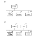
- FIG. 2A is a block diagram showing a hardware configuration for realizing the function of the plant growth promoting apparatus according to the first embodiment.
- FIG. 2B is a block diagram showing a hardware configuration for executing software for realizing the function of the plant growth promoting apparatus according to the first embodiment.
- 1 is a flowchart showing a plant growth promotion method according to Embodiment 1.
- FIG. 4A is a photograph showing the growth condition of sweet potato irradiated with ultrasonic waves.
- FIG. 4B is a photograph showing the growth state of sweet potato not irradiated with ultrasonic waves.
- FIG. 4A is a photograph showing the growth condition of sweet potato irradiated with ultrasonic waves.
- FIG. 2 is a diagram showing an outline of ultrasonic wave irradiation to seeds by the plant growth promoting apparatus according to the first embodiment. It is a figure which shows the received signal waveform of the ultrasonic wave reflected by the seed.
- FIG. 6 is a diagram showing an outline of ultrasonication on a germinated plant by the plant growth promoting apparatus according to the first embodiment. It is a figure which shows the received signal waveform of the ultrasonic wave reflected by the sprouted plant. It is a block diagram which shows the structure of the plant growth promotion apparatus which concerns on Embodiment 2 of this invention.
- 7 is a flowchart showing a plant growth promotion method according to Embodiment 2.
- FIG. 2 is a diagram showing an outline of ultrasonic wave irradiation to seeds by the plant growth promoting apparatus according to the first embodiment. It is a figure which shows the received signal waveform of the ultrasonic wave reflected by the seed.
- FIG. 6 is a diagram showing an outline of ultrasonication on
- FIG. 1 is a block diagram showing a configuration of a plant growth promoting apparatus 1 according to Embodiment 1 of the present invention.
- the plant growth promoting apparatus 1 is an apparatus for irradiating the target plant A with ultrasonic waves to promote its growth, and as shown in FIG. 1, the ultrasonic sensor 2, the transmitting unit 3, the receiving unit 4, and the temperature control unit 5. , A growth amount measuring unit 6 and a control unit 7.
- the ultrasonic sensor 2 is an ultrasonic element that transmits ultrasonic waves to the target plant A and receives ultrasonic waves reflected from the target plant A.
- the ultrasonic sensor 2 includes a piezoelectric vibrator.
- the piezoelectric vibrator converts the electric signal applied by the transmitter 3 into an ultrasonic wave and emits the ultrasonic wave, and converts the ultrasonic wave reflected from the object into an electric signal.
- the electrical signal converted from the ultrasonic wave by the piezoelectric vibrator is output to the receiving unit 4.
- the transmitter 3 controls the ultrasonic sensor 2 to transmit ultrasonic waves to the target plant A.
- the transmission unit 3 controls the application of the electrical signal to the piezoelectric vibrator of the ultrasonic sensor 2 to transmit ultrasonic waves to the target plant A at a preset frequency, irradiation interval, and irradiation time.
- the receiving unit 4 acquires a received signal of the ultrasonic wave received by the ultrasonic sensor 2.
- the receiving unit 4 acquires an electrical signal input from the piezoelectric vibrator of the ultrasonic sensor 2 as a reception signal of ultrasonic waves.
- the temperature control unit 5 adjusts the ambient temperature of the target plant A.
- the temperature control unit 5 adjusts the ambient temperature of the target plant A so as to be the temperature specified by the control unit 7 using an air conditioner (not shown).
- the temperature control unit 5 may adjust the ambient temperature of the target plant A using a heater and a cooler.
- the temperature control unit 5 may adjust the ambient temperature of the target plant A by controlling the irradiation state of light to the target plant A.
- an irradiation state of light for example, the intensity of light can be mentioned.
- the growth amount measuring unit 6 measures the growth amount of the target plant A based on the reception signal of the ultrasonic wave acquired by the receiving unit 4. For example, the growth amount measurement unit 6 measures the distance from the ultrasonic sensor 2 to the target plant A based on the reception signal of the ultrasonic wave acquired by the reception unit 4.
- the growth amount measuring unit 6 refers to the table data in which the distance from the ultrasonic sensor 2 to the plant and the corresponding growth amount of the plant are registered based on the measured distance, and thereby the growth of the plant. Identify the quantity.
- the growth amount of the plant corresponding to the distance from the ultrasonic sensor 2 to the plant is determined, for example, by prior experiments.
- the control unit 7 controls the temperature control unit 5 based on the growth amount of the target plant A measured by the growth amount measurement unit 6 so that the ambient temperature corresponds to the growth condition of the target plant A.
- the ambient temperature corresponding to the growth status of the target plant A is the ambient temperature at which the target plant A is estimated to grow most rapidly to the target growth status, and is determined by, for example, previous experiments.
- the control unit 7 refers to the table data in which the growth amount of the target plant A and the ambient temperature corresponding thereto are registered based on the growth amount of the target plant A, and corresponds to the growth situation of the target plant A Identify the ambient temperature.
- the control unit 7 designates the ambient temperature specified from the table data in the temperature control unit 5. Thereby, the temperature control unit 5 adjusts the ambient temperature of the target plant A so that the temperature specified by the control unit 7 is reached.
- FIG. 2A is a block diagram showing a hardware configuration for realizing the function of the plant growth promotion device 1.
- FIG. 2B is a block diagram showing a hardware configuration for executing software for realizing the function of the plant growth promotion apparatus 1.
- the ultrasonic sensor device 100 corresponds to the ultrasonic sensor 2 shown in FIG.
- the temperature controller 101 corresponds to the temperature controller 5 shown in FIG.
- the storage device 102 stores the measured growth amount of the target plant A, and the table data as described above.
- the plant growth promoting apparatus 1 includes a processing circuit for executing the processing from step ST1 to step ST4 described later with reference to FIG.
- the processing circuit may be dedicated hardware or may be a CPU (Central Processing Unit) that executes a program stored in a memory.
- the processing circuit 103 may be, for example, a single circuit, a complex circuit, a programmed processor, a parallel programmed processor, or an ASIC (Application Specific Integrated Circuit). ), FPGA (Field-Programmable Gate Array), or a combination thereof.
- the respective functions of the transmitting unit 3, the receiving unit 4, the growth amount measuring unit 6, and the control unit 7 may be realized by separate processing circuits, or these functions may be realized collectively by one processing circuit. .
- the processing circuit is the processor 104 shown in FIG. 2B
- the functions of the transmitting unit 3, the receiving unit 4, the growth amount measuring unit 6, and the control unit 7 are realized by software, firmware or a combination of software and firmware.
- the software or firmware is written as a program and stored in the memory 105.
- the processor 104 reads out and executes the program stored in the memory 105 to realize the respective functions of the transmitting unit 3, the receiving unit 4, the growth amount measuring unit 6 and the control unit 7. That is, the plant growth promotion apparatus 1 is provided with the memory 105 for storing the program in which the process from step ST1 to step ST4 shown in FIG. 3 is executed as it is executed by the processor 104. These programs cause a computer to execute the procedure or method of the transmission unit 3, the reception unit 4, the growth amount measurement unit 6 and the control unit 7.
- the memory 105 may be a computer readable storage medium storing a program for causing a computer to function as the transmitting unit 3, the receiving unit 4, the growth amount measuring unit 6, and the control unit 7.
- the memory 105 may be, for example, a nonvolatile or volatile semiconductor memory such as a random access memory (RAM), a read only memory (ROM), a flash memory, an erasable programmable read only memory (EPROM), or an EEPROM (electrically-EPROM).
- RAM random access memory
- ROM read only memory
- EPROM erasable programmable read only memory
- EEPROM electrically-EPROM
- a magnetic disk, a flexible disk, an optical disk, a compact disk, a mini disk, a DVD, etc. correspond.
- the memory 105 may be an external memory such as a USB (Universal Serial Bus) memory.
- USB Universal Serial Bus
- a part of each function of the transmitting unit 3, the receiving unit 4, the growth amount measuring unit 6 and the control unit 7 may be realized by dedicated hardware and a part may be realized by software or firmware.
- the functions of the transmission unit 3 and the reception unit 4 are realized by a processing circuit that is dedicated hardware.
- the growth amount measuring unit 6 and the control unit 7 may realize functions by the processor 104 reading and executing a program stored in the memory 105.
- the processing circuit can realize each of the above functions by hardware, software, firmware or a combination thereof.
- FIG. 3 is a flow chart showing a plant growth promotion method according to the first embodiment.
- the ultrasonic sensor 2 transmits an ultrasonic wave to the target plant A.
- the transmitter 3 applies an electric signal to the ultrasonic sensor 2 to transmit ultrasonic waves of a certain frequency and intensity toward the target plant A.
- the target plant A receives physical stimulation by ultrasound to promote growth.
- FIG. 4A is a photograph showing the growth condition of sweet potato irradiated with ultrasonic waves.
- FIG. 4B is a photograph showing the growth state of sweet potato not irradiated with ultrasonic waves.
- FIG. 4A and FIG. 4B show the growth status of sweet potato placed in a container filled with water.
- FIG. 4A shows the growth state of sweet potato after continuously applying ultrasonic waves with a frequency of 58 kHz to the sweet potato every 50 milliseconds for one month.
- FIG. 4B shows the growth state of sweet potato after one month has passed without irradiation of ultrasonic waves.
- the sweet potato shown in FIG. 4A and the sweet potato shown in FIG. 4B are almost the same environmental conditions except for the presence or absence of the ultrasonic wave, but the sweet potato in FIG. 4B which is not irradiated with the ultrasonic wave is almost grown Absent.
- the sweet potato shown to FIG. 4A which irradiated the ultrasonic wave was growing notably. This growth tendency is the same for plants other than sweet potato, and ultrasonic irradiation is effective for promoting the growth of plants.
- the irradiation conditions of the ultrasonic waves such as the frequency of the ultrasonic waves, the irradiation interval, and the irradiation time may be appropriately changed according to the type of the target plant A.
- the reception unit 4 acquires the reception signal of the ultrasonic wave received by the ultrasonic sensor 2.
- the ultrasonic waves transmitted from the ultrasonic sensor 2 reach the target plant A, they give physical stimulus to the target plant A as described above, and are reflected from the target plant A.
- the ultrasonic waves reflected by the target plant A propagate in the air, reach the ultrasonic sensor 2 and are received.
- the ultrasonic sensor 2 converts the received ultrasonic wave into an electric signal and outputs the electric signal to the receiving unit 4.
- the reception signal of the ultrasonic wave reflected from the target plant A is acquired by the reception unit 4.
- the received signal includes time information from when the ultrasonic wave is transmitted from the ultrasonic sensor 2 until it is reflected by the target plant A and the reflected wave is received by the ultrasonic sensor 2.
- the reception signal of the ultrasonic wave acquired by the reception unit 4 is output to the growth amount measurement unit 6.
- the growth amount measuring unit 6 measures the growth amount of the target plant A based on the reception signal of the ultrasonic wave acquired by the receiving unit 4. For example, the growth amount measuring unit 6 calculates distance information from the ultrasonic sensor 2 to the target plant A based on time information included in the received signal, and measures the growth amount of the target plant A based on the calculated distance information Do.
- FIG. 5 is a view showing an outline of the ultrasonic wave irradiation to the seed a1 by the plant growth promoting device 1, and shows a case where the ultrasonic sensor 2 irradiates the ultrasonic wave to the seed a1 sowed on the ground B.
- FIG. 6 is a diagram showing a received signal waveform of the ultrasonic wave reflected by the seed a1, and shows a waveform of the received signal which is converted from an ultrasonic wave into an electric signal by the ultrasonic sensor 2 and output to the receiving unit 4.
- the horizontal axis is time
- the vertical axis is received voltage.
- the ultrasonic waves emitted from the ultrasonic sensor 2 toward the seed a1 give physical stimulation to the seed a1 and are reflected by the ground B or the seed a1.
- the ultrasonic wave reflected by the ground B or the seed a1 propagates in the air, reaches the ultrasonic sensor 2, and is received.
- the large amplitude from 1.1 seconds to 1.3 seconds in the waveform shown in FIG. 6 corresponds to the amplitude of the reception signal of the ultrasonic wave reflected by the ground B or the seed a1. That is, during the time from 1.1 seconds to 1.3 seconds, an ultrasonic wave is transmitted from the ultrasonic sensor 2 and reflected by the ground B or the seed a 1 until the reflected wave is received by the ultrasonic sensor 2. It's time.
- the growth amount measuring unit 6 calculates the distance from the ultrasonic sensor 2 to the seed a1 using this time and the speed of sound, assuming that the size of the seed a1 is very small.
- FIG. 7 is a diagram showing an outline of the ultrasonic wave irradiation to the germinated plant A1 by the plant growth promoting device 1, and the ultrasonic sensor 2 applies ultrasonic waves to the plant A1 germinated from the seed a1 shown in FIG. It shows the case of irradiation.
- FIG. 8 is a diagram showing a received signal waveform of the ultrasonic wave reflected by the germinated plant A1, and the waveform of the received signal which is converted from an ultrasonic wave into an electric signal by the ultrasonic sensor 2 and output to the receiving unit 4 is shown. It shows. Also in FIG. 8, the horizontal axis is time, and the vertical axis is the reception voltage.
- the ultrasonic waves emitted from the ultrasonic sensor 2 toward the plant A1 physically stimulate the plant A1 and are reflected by the ground B or the plant A1.
- the ultrasonic wave reflected by the ground B or the plant A1 propagates in the air, reaches the ultrasonic sensor 2, and is received.
- the large amplitude from 1.1 seconds to 1.3 seconds in the waveform shown in FIG. 8 corresponds to the amplitude of the reception signal of the ultrasonic wave reflected by the ground B.
- the amplitude from 0.9 seconds to 1.0 seconds corresponds to the amplitude of the reception signal of the ultrasonic wave reflected by the germinating plant A1. That is, the time from 0.9 seconds to 1.0 seconds is the time until the ultrasonic wave is transmitted from the ultrasonic sensor 2 and reflected by the plant A1 and the reflected wave is received by the ultrasonic sensor 2 .
- the growth amount measuring unit 6 calculates the distance from the ultrasonic sensor 2 to the plant A1 using this time and the speed of sound.
- the growth amount measuring unit 6 calculates the distance information from the ultrasonic sensor 2 to the seed a1 when the breeding is started from the seed a1, and the difference from the distance information from the ultrasonic sensor 2 to the plant A1 calculated thereafter Measure the growth amount of plant A1. Information on the measured growth amount is output from the growth amount measurement unit 6 to the transmission unit 3 and the control unit 7.
- the control unit 7 controls the temperature control unit 5 based on the growth amount of the target plant A measured by the growth amount measurement unit 6 so that the ambient temperature corresponds to the growth state of the target plant A.
- the control unit 7 refers to table data in which the growth amount of the target plant A and the ambient temperature corresponding thereto are registered based on the growth amount of the target plant A, and corresponds to the growth state of the target plant A Identify the ambient temperature.
- the control unit 7 designates the ambient temperature specified from the table data in the temperature control unit 5. Thereby, the temperature control unit 5 adjusts the ambient temperature of the target plant A so that the temperature specified by the control unit 7 is reached.
- the relationship between the growth process of a plant and the environmental temperature will be described.
- Plants have a temperature suitable for germination or raising seedlings, and the environmental temperature greatly affects the growth of plants.
- the optimum germination temperature and the appropriate temperature for raising seedlings vary depending on the type of plant, but generally the optimum temperature for germination tends to be higher than the appropriate temperature for raising seedlings. Therefore, in order to promote the growth of plants, it is required to set the environmental temperature suitable for the growth conditions of plants. For example, an environmental temperature suitable for a period until germination from seeds is set, and in a period after germination, an environmental temperature lower than a period until germination from seeds is set.
- the transmitting unit 3 may change the state of the ultrasonic wave transmitted from the ultrasonic sensor 2 to the target plant A based on the growth amount of the target plant A measured by the growth amount measuring unit 6. For example, the transmission unit 3 changes the intensity of the ultrasonic wave transmitted from the ultrasonic sensor 2 to the target plant A.
- the transmitting unit 3 refers to the table data in which the growth amount of the target plant A and the corresponding ultrasonic intensity are registered based on the growth amount of the target plant A, and the growth state of the target plant A Identify the intensity of the ultrasound corresponding to The transmitter 3 applies to the ultrasonic sensor 2 an electrical signal corresponding to the intensity of the ultrasonic wave specified from the table data.
- the ultrasonic sensor 2 irradiates the target plant A with the ultrasonic wave of the intensity corresponding to the growth condition of the target plant A.
- the intensity of the ultrasonic wave corresponding to the growth condition of the target plant A is the intensity of the ultrasonic wave estimated that the target plant A will grow most quickly to the target growth condition, and is determined by, for example, previous experiments. .
- the transmitting unit 3 controls the ultrasonic sensor 2 to transmit ultrasonic waves to the target plant A.
- the receiving unit 4 acquires a received signal of the ultrasonic wave received by the ultrasonic sensor 2.
- the temperature control unit 5 adjusts the ambient temperature of the target plant A.
- the growth amount measuring unit 6 measures the growth amount of the target plant A based on the reception signal of the ultrasonic wave acquired by the receiving unit 4.
- the control unit 7 controls the temperature control unit 5 based on the growth amount of the target plant A measured by the growth amount measurement unit 6 so that the ambient temperature corresponds to the growth condition of the target plant A.
- the plant growth promoting apparatus 1 controls the ambient temperature corresponding to the growth condition of the target plant A, the growth of the target plant A can be promoted.
- the transmitting unit 3 transmits the ultrasonic wave transmitted from the ultrasonic sensor 2 to the target plant A based on the growth amount of the target plant A measured by the growth amount measuring unit 6. Change the condition of the sound wave. As described above, since the plant growth promoting apparatus 1 controls the ultrasonic wave corresponding to the growth condition of the target plant A, the growth of the target plant A can be promoted.
- FIG. 9 is a block diagram showing a configuration of a plant growth promoting apparatus 1A according to Embodiment 2 of the present invention.
- the plant growth promoting apparatus 1A is an apparatus for irradiating the target plant A with ultrasonic waves to promote the growth thereof, and includes an ultrasonic sensor 2a, an ultrasonic sensor 2b, a transmitting unit 3A, a receiving unit 4, and a temperature control unit 5. , A growth amount measuring unit 6 and a control unit 7.
- the plant growth promotion device 1A includes a plurality of ultrasonic sensors.
- the ultrasonic sensor 2a is an ultrasonic element that transmits ultrasonic waves to the target plant A and receives ultrasonic waves reflected from the target plant A.
- the ultrasonic sensor 2a includes a piezoelectric vibrator.
- the piezoelectric vibrator converts the electric signal applied by the transmitter 3A into an ultrasonic wave and emits it, and converts the ultrasonic wave reflected from the object into an electric signal.
- the electrical signal converted from the ultrasonic wave by the piezoelectric vibrator is output to the receiving unit 4.
- the ultrasonic sensor 2b is an ultrasonic element that transmits ultrasonic waves in a frequency band different from that of the ultrasonic sensor 2a to the target plant A and receives ultrasonic waves reflected from the target plant A. That is, the ultrasonic sensor 2a and the ultrasonic sensor 2b radiate ultrasonic waves in different frequency bands.
- the frequency of ultrasound corresponding to the growth status of the target plant A is the frequency of ultrasound estimated that the target plant A will grow most rapidly to the target growth status, and is determined by, for example, previous experiments.
- the transmitter 3A controls the ultrasonic sensor 2a and the ultrasonic sensor 2b to transmit ultrasonic waves to the target plant A.
- the transmission unit 3A transmits the ultrasonic wave to the target plant A at a preset frequency, irradiation interval, and irradiation time by controlling the application of the electric signal to the piezoelectric vibrator of the ultrasonic sensor 2a.
- the transmitting unit 3A applies, to the target plant A, an ultrasonic wave whose frequency has been changed in a frequency band that can be generated by the ultrasonic sensor 2a based on the growth amount of the target plant A measured by the growth amount measuring unit 6. It may be sent.
- the transmitter 3A transmits an ultrasonic sensor for transmitting the ultrasonic wave to the target plant A from the ultrasonic sensor 2a to the ultrasonic sensor 2b. You may switch.
- the plant growth promoting apparatus 1A includes a processing circuit for executing the processing from step ST1a to step ST4a described later with reference to FIG.
- the processing circuit may be the dedicated hardware processing circuit 103 shown in FIG. 2A, or may be a processor 104 that executes a program stored in the memory 105 as shown in FIG. 2B.
- FIG. 10 is a flowchart showing a plant growth promotion method according to the second embodiment.
- the processing from step ST1a to step ST3a is the same as that from step ST1 to step ST3 shown in FIG.
- the ultrasonic sensor 2a is selected first as an ultrasonic sensor that causes the target plant A to transmit ultrasonic waves.
- step ST4a the control unit 7 controls the temperature control unit 5 based on the growth amount of the target plant A measured by the growth amount measurement unit 6 so that the ambient temperature corresponds to the growth state of the target plant A.
- the control unit 7 refers to table data in which the growth amount of the target plant A and the ambient temperature corresponding thereto are registered, The ambient temperature corresponding to the growth condition of the target plant A is specified.
- the control unit 7 specifies the ambient temperature specified from the table data to the temperature control unit 5. Thereby, the temperature control unit 5 adjusts the ambient temperature of the target plant A so that the temperature specified by the control unit 7 is reached.
- the transmitting unit 3A can control the application of the electrical signal to the piezoelectric vibrator of the ultrasonic sensor 2a based on the growth amount of the target plant A measured by the growth amount measuring unit 6, and can generate the ultrasonic sensor 2a.
- the target plant A is caused to transmit ultrasonic waves whose frequency has been changed within the frequency band.
- the transmitting unit 3A is an ultrasonic sensor that causes the target plant A to transmit an ultrasonic wave when the target plant A further grows based on the growth amount of the target plant A measured by the growth amount measuring unit 6,
- the ultrasonic sensor 2a is switched to the ultrasonic sensor 2b.
- the transmitting unit 3A registers table data in which the growth amount of the target plant A and the frequency of the ultrasonic wave corresponding thereto are registered.
- the frequency of the ultrasonic wave corresponding to the growth condition of the target plant A is specified with reference.
- the transmitting unit 3A transmits the ultrasonic wave sensor for transmitting the ultrasonic wave to the target plant A to the ultrasonic wave sensor for transmitting the ultrasonic wave of the frequency specified from the table data among the ultrasonic wave sensor 2a and the ultrasonic wave sensor 2b. Switch. It is assumed that the ultrasonic sensor 2a is switched to the ultrasonic sensor 2b.
- the transmission unit 3A transmits the ultrasonic wave to the target plant A at a preset frequency, irradiation interval and irradiation time by controlling the application of the electric signal to the piezoelectric vibrator of the ultrasonic sensor 2b. Thereby, the target plant A is irradiated with the ultrasonic wave of the frequency corresponding to the growing condition at that time.
- the plant growth promoting apparatus 1A irradiates ultrasonic waves to promote the growth of the target plant A, and sets the ambient temperature, the intensity and the frequency of ultrasonic waves corresponding to the growth state of the target plant A. Thereby, the growth of the target plant A can be promoted more efficiently than the plant growth promotion device 1 according to the first embodiment.
- the plant growth promotion apparatus 1A showed the structure provided with two ultrasonic sensors in FIG. 9, it is not limited to this.
- the plant growth promotion device 1A may be provided with three or more ultrasonic sensors. Good.
- the transmitting unit 3A selects the target plant A from the ultrasonic sensor 2a and the ultrasonic sensor 2b based on the growth amount of the target plant A. Switch the ultrasonic sensor that transmits ultrasonic waves.
- the plant growth promoting apparatus 1A can promote the growth of the target plant A more efficiently than the plant growth promoting apparatus 1 according to the first embodiment.
- the present invention is not limited to the above embodiment, and within the scope of the present invention, variations or embodiments of respective free combinations of the embodiments or respective optional components of the embodiments.
- An optional component can be omitted in each of the above.
- the plant growth promoting apparatus according to the present invention can promote the growth of plants, and therefore can be used as equipment of a plant factory.
- 1,1A plant growth promoter 2,2a, 2b ultrasonic sensor, 3,3A transmitter, 4 receiver, 5 temperature controller, 6 growth amount measuring unit, 7 controller, 100 ultrasonic sensor device, 101 temperature Controller, 102 storage units, 103 processing circuits, 104 processors, 105 memories.
Abstract
超音波センサ(2)は、対象植物(A)に超音波を送信し、対象植物(A)から反射された超音波を受信する。送信部(3)は、超音波センサ(2)を制御して対象植物(A)に超音波を送信させる。受信部(4)が、超音波センサ(2)によって受信された超音波の受信信号を取得する。温度調節部(5)は、対象植物(A)の周囲温度を調節する。生長量計測部(6)は、超音波の受信信号に基づいて、対象植物(A)の生長量を計測する。制御部(7)は、計測された対象植物(A)の生長量に基づいて、対象植物(A)の生長状況に対応した周囲温度になるように温度調節部(5)を制御する。
Description
この発明は、植物の生長を促進させる植物生長促進装置および植物生長促進方法に関する。
近年、植物を供給する植物工場が注目されている。植物工場では、植物が生長するために必要な光、温度、湿度および栄養分といった環境条件が人工的に制御される。環境条件の人工的な制御には大電力が必要であるため、植物工場における植物の栽培期間の短縮化が要望されている。例えば、特許文献1には、農作物の育成農地全体に可聴周波数および超音波周波数の音波を発生させることにより、農作物の防病と生長促進を図る方法が記載されている。
植物の生長を促進させる従来の技術は、音波によって植物に物理的な刺激を与えて生長を促進させるものである。しかしながら、従来の技術では、植物の生長状況と植物の周辺温度とが別々に管理されているため、植物の生長を促進させる効果が十分に得られないという課題があった。
この発明は上記課題を解決するものであり、植物の生長を促進させることができる植物生長促進装置および植物生長促進方法を得ることを目的とする。
この発明に係る植物生長促進装置は、超音波素子、送信部、受信部、温度調節部、生長量計測部および制御部を備えている。超音波素子は、植物に超音波を送信し、植物から反射されてきた超音波を受信する。送信部は、超音波素子を制御して植物に超音波を送信させる。受信部が、超音波素子によって受信された超音波の受信信号を取得する。温度調節部は、植物の周囲温度を調節する。生長量計測部は、受信部によって取得された超音波の受信信号に基づいて植物の生長量を計測する。制御部は、生長量計測部によって計測された植物の生長量に基づいて、植物の生長状況に対応した周囲温度になるように温度調節部を制御する。
この発明によれば、植物生長促進装置が植物の生長状況に対応した周囲温度に制御するので、植物の生長を促進させることができる。
以下、この発明をより詳細に説明するため、この発明を実施するための形態について、添付の図面に従って説明する。
実施の形態1.
図1は、この発明の実施の形態1に係る植物生長促進装置1の構成を示すブロック図である。植物生長促進装置1は、対象植物Aに超音波を照射してその生長を促進させる装置であり、図1に示すように、超音波センサ2、送信部3、受信部4、温度調節部5、生長量計測部6および制御部7を備える。
実施の形態1.
図1は、この発明の実施の形態1に係る植物生長促進装置1の構成を示すブロック図である。植物生長促進装置1は、対象植物Aに超音波を照射してその生長を促進させる装置であり、図1に示すように、超音波センサ2、送信部3、受信部4、温度調節部5、生長量計測部6および制御部7を備える。
超音波センサ2は、対象植物Aに超音波を送信し、対象植物Aから反射されてきた超音波を受信する超音波素子である。例えば、超音波センサ2は、圧電振動体を備える。圧電振動体は、送信部3が印加した電気信号を超音波に変換して放射し、対象物から反射されてきた超音波を電気信号に変換する。圧電振動体によって超音波から変換された電気信号は、受信部4に出力される。
送信部3は、超音波センサ2を制御して対象植物Aに超音波を送信させる。例えば、送信部3は、超音波センサ2の圧電振動体に対する電気信号の印加を制御することにより、予め設定された周波数、照射間隔および照射時間で、超音波を対象植物Aに送信させる。受信部4は、超音波センサ2によって受信された超音波の受信信号を取得する。例えば、受信部4は、超音波センサ2の圧電振動体から入力した電気信号を、超音波の受信信号として取得する。
温度調節部5は、対象植物Aの周囲温度を調節する。例えば、温度調節部5は、不図示の空調装置を利用して、制御部7から指定された温度になるように対象植物Aの周囲温度を調節する。なお、空調装置に限らず、温度調節部5は、ヒーターおよび冷却器を利用して対象植物Aの周囲温度を調節してもよい。また、温度調節部5は、対象植物Aに対する光の照射状態を制御することにより、対象植物Aの周囲温度を調節してもよい。光の照射状態としては、例えば、光の強度が挙げられる。
生長量計測部6は、受信部4によって取得された超音波の受信信号に基づいて、対象植物Aの生長量を計測する。例えば、生長量計測部6は、受信部4によって取得された超音波の受信信号に基づいて、超音波センサ2から対象植物Aまでの距離を計測する。生長量計測部6は、計測した距離に基づいて、超音波センサ2から植物までの距離とこれに対応する当該植物の生長量とが登録されたテーブルデータを参照することにより、当該植物の生長量を特定する。超音波センサ2から植物までの距離に対応する当該植物の生長量は、例えば、事前の実験によって決定される。
制御部7は、生長量計測部6によって計測された対象植物Aの生長量に基づいて、対象植物Aの生長状況に対応した周囲温度になるように温度調節部5を制御する。
対象植物Aの生長状況に対応した周囲温度とは、対象植物Aが目標の生長状況まで最も早く生長すると推定される周囲温度であり、例えば、事前の実験によって決定される。
また、制御部7は、対象植物Aの生長量に基づいて、対象植物Aの生長量とこれに対応した周囲温度とが登録されたテーブルデータを参照し、対象植物Aの生長状況に対応した周囲温度を特定する。制御部7は、上記テーブルデータから特定した周囲温度を温度調節部5に指定する。これにより、温度調節部5は、制御部7から指定された温度になるように対象植物Aの周囲温度を調節する。
対象植物Aの生長状況に対応した周囲温度とは、対象植物Aが目標の生長状況まで最も早く生長すると推定される周囲温度であり、例えば、事前の実験によって決定される。
また、制御部7は、対象植物Aの生長量に基づいて、対象植物Aの生長量とこれに対応した周囲温度とが登録されたテーブルデータを参照し、対象植物Aの生長状況に対応した周囲温度を特定する。制御部7は、上記テーブルデータから特定した周囲温度を温度調節部5に指定する。これにより、温度調節部5は、制御部7から指定された温度になるように対象植物Aの周囲温度を調節する。
図2Aは、植物生長促進装置1の機能を実現するハードウェア構成を示すブロック図である。図2Bは、植物生長促進装置1の機能を実現するソフトウェアを実行するハードウェア構成を示すブロック図である。図2Aおよび図2Bにおいて、超音波センサ装置100は、図1に示した超音波センサ2に相当する。温度調節器101は、図1に示した温度調節部5に相当する。記憶装置102は、計測された対象植物Aの生長量、および前述したようなテーブルデータを記憶する。
植物生長促進装置1における、送信部3、受信部4、生長量計測部6および制御部7のそれぞれの機能は、処理回路により実現される。すなわち、植物生長促進装置1は、図3を用いて後述するステップST1からステップST4までの処理を実行するための処理回路を備える。処理回路は、専用のハードウェアであってもよいが、メモリに記憶されたプログラムを実行するCPU(Central Processing Unit)であってもよい。
処理回路が図2Aに示す専用のハードウェアの処理回路103である場合、処理回路103は、例えば、単一回路、複合回路、プログラム化したプロセッサ、並列プログラム化したプロセッサ、ASIC(Application Specific Integrated Circuit)、FPGA(Field-Programmable Gate Array)、または、これらを組み合わせたものが該当する。送信部3、受信部4、生長量計測部6および制御部7のそれぞれの機能を別々の処理回路で実現してもよいし、これらの機能をまとめて1つの処理回路で実現してもよい。
処理回路が図2Bに示すプロセッサ104である場合、送信部3、受信部4、生長量計測部6および制御部7のそれぞれの機能は、ソフトウェア、ファームウェアまたはソフトウェアとファームウェアとの組み合わせによって実現される。ソフトウェアまたはファームウェアは、プログラムとして記述されて、メモリ105に記憶される。
プロセッサ104は、メモリ105に記憶されたプログラムを読み出して実行することにより、送信部3、受信部4、生長量計測部6および制御部7のそれぞれの機能を実現する。すなわち、植物生長促進装置1は、プロセッサ104によって実行されるときに、図3に示すステップST1からステップST4までの処理が結果的に実行されるプログラムを記憶するためのメモリ105を備えている。これらのプログラムは、送信部3、受信部4、生長量計測部6および制御部7の手順または方法をコンピュータに実行させるものである。メモリ105は、送信部3、受信部4、生長量計測部6および制御部7として、コンピュータを機能させるためのプログラムが記憶されたコンピュータ可読記憶媒体であってもよい。
メモリ105には、例えば、RAM(Random Access Memory)、ROM(Read Only Memory)、フラッシュメモリ、EPROM(Erasable Programmable Read Only Memory)、EEPROM(Electrically-EPROM)などの不揮発性または揮発性の半導体メモリ、磁気ディスク、フレキシブルディスク、光ディスク、コンパクトディスク、ミニディスク、DVDなどが該当する。また、メモリ105は、USB(Universal Serial Bus)メモリといった外部メモリであってもよい。
送信部3、受信部4、生長量計測部6および制御部7のそれぞれの機能について一部を専用のハードウェアで実現し、一部をソフトウェアまたはファームウェアで実現してもよい。例えば、送信部3および受信部4については、専用のハードウェアである処理回路で機能を実現する。生長量計測部6および制御部7については、プロセッサ104がメモリ105に記憶されたプログラムを読み出して実行することにより機能を実現してもよい。このように、処理回路は、ハードウェア、ソフトウェア、ファームウェアまたはこれらの組み合わせにより上記機能のそれぞれを実現することができる。
次に動作について説明する。
図3は、実施の形態1に係る植物生長促進方法を示すフローチャートである。
ステップST1において、超音波センサ2が対象植物Aに超音波を送信する。例えば、送信部3が、超音波センサ2に電気信号を印加することにより、一定の周波数および強度の超音波が対象植物Aに向けて送信される。対象植物Aは、超音波によって物理的な刺激を受けて生長が促進される。
図3は、実施の形態1に係る植物生長促進方法を示すフローチャートである。
ステップST1において、超音波センサ2が対象植物Aに超音波を送信する。例えば、送信部3が、超音波センサ2に電気信号を印加することにより、一定の周波数および強度の超音波が対象植物Aに向けて送信される。対象植物Aは、超音波によって物理的な刺激を受けて生長が促進される。
図4Aは、超音波を照射したサツマイモの生長状況を示す写真である。図4Bは、超音波を照射しなかったサツマイモの生長状況を示す写真である。図4Aおよび図4Bは、水を入れた容器に配置されたサツマイモの生長状況を示している。図4Aは、サツマイモに対して50ミリ秒ごとに周波数58kHzの超音波を照射することを、1ヶ月間継続的に行った後のサツマイモの生長状況を示している。図4Bは、超音波を照射せずに、1ヶ月経過した後のサツマイモの生長状況を示している。
図4Aに示すサツマイモおよび図4Bに示すサツマイモは、超音波の照射の有無以外は全く同じ環境条件であったにもかかわらず、超音波を照射していない図4Bのサツマイモは、ほとんど生長していない。これに対して、超音波を照射した図4Aに示すサツマイモが顕著に生長していた。この生長傾向は、サツマイモ以外の植物においても同様であり、植物の成長促進には超音波の照射が有効である。なお、超音波の周波数、照射間隔および照射時間といった超音波の照射条件は、対象植物Aの種類によって適宜変更してもよい。
図3の説明に戻る。
ステップST2において、受信部4が、超音波センサ2によって受信された超音波の受信信号を取得する。超音波センサ2から送信された超音波は、対象植物Aに到達すると、前述したように対象植物Aに物理的な刺激を与えるとともに、対象植物Aで反射される。対象植物Aで反射された超音波は、空気中を伝搬して超音波センサ2に到達して受信される。超音波センサ2は、受信した超音波を電気信号に変換して受信部4に出力する。
ステップST2において、受信部4が、超音波センサ2によって受信された超音波の受信信号を取得する。超音波センサ2から送信された超音波は、対象植物Aに到達すると、前述したように対象植物Aに物理的な刺激を与えるとともに、対象植物Aで反射される。対象植物Aで反射された超音波は、空気中を伝搬して超音波センサ2に到達して受信される。超音波センサ2は、受信した超音波を電気信号に変換して受信部4に出力する。
このようにして、対象植物Aから反射された超音波の受信信号は、受信部4に取得される。この受信信号には、超音波センサ2から超音波が送信された時点から、対象植物Aで反射されて、超音波センサ2に反射波が受信されるまでの時間情報が含まれている。
受信部4によって取得された超音波の受信信号は、生長量計測部6に出力される。
受信部4によって取得された超音波の受信信号は、生長量計測部6に出力される。
ステップST3において、生長量計測部6が、受信部4によって取得された超音波の受信信号に基づいて対象植物Aの生長量を計測する。例えば、生長量計測部6は、受信信号に含まれる時間情報に基づいて超音波センサ2から対象植物Aまでの距離情報を算出し、算出した距離情報に基づいて対象植物Aの生長量を計測する。
図5は、植物生長促進装置1による種子a1への超音波照射の概要を示す図であり、地面Bに蒔かれた種子a1に対して超音波センサ2が超音波を照射した場合を示している。図6は、種子a1で反射された超音波の受信信号波形を示す図であり、超音波センサ2によって超音波から電気信号に変換されて受信部4に出力された受信信号の波形を示している。図6において、横軸は時間、縦軸は受信電圧である。
図5の矢印で示すように、超音波センサ2から種子a1に向けて照射された超音波は、種子a1に物理的な刺激を与えるとともに、地面Bまたは種子a1で反射される。地面Bまたは種子a1で反射された超音波は、空気中を伝搬して超音波センサ2に到達して受信される。
図6に示す波形における1.1秒から1.3秒までの大きな振幅は、地面Bまたは種子a1で反射された超音波の受信信号の振幅に相当する。すなわち、1.1秒から1.3秒までの時間は、超音波センサ2から超音波が送信され、地面Bまたは種子a1で反射されて、反射波が超音波センサ2によって受信されるまでの時間である。生長量計測部6は、この時間と音速とを用い、種子a1の大きさが非常に小さいと仮定して、超音波センサ2から種子a1までの距離を算出する。
図7は、植物生長促進装置1による発芽した植物A1への超音波照射の概要を示す図であり、図5に示した種子a1から発芽した植物A1に対して超音波センサ2が超音波を照射した場合を示している。図8は、発芽した植物A1で反射された超音波の受信信号波形を示す図であり、超音波センサ2によって超音波から電気信号に変換されて受信部4に出力された受信信号の波形を示している。図8においても、横軸は時間、縦軸は受信電圧である。
図7の矢印で示すように、超音波センサ2から植物A1に向けて照射された超音波は、植物A1に物理的な刺激を与えるとともに、地面Bまたは植物A1で反射される。地面Bまたは植物A1で反射された超音波は、空気中を伝搬して超音波センサ2に到達して受信される。
図8に示す波形における1.1秒から1.3秒までの大きな振幅は、地面Bで反射された超音波の受信信号の振幅に相当する。一方、0.9秒から1.0秒までの振幅は、発芽した植物A1で反射された超音波の受信信号の振幅に相当する。すなわち、0.9秒から1.0秒までの時間は、超音波センサ2から超音波が送信され、植物A1で反射されて、反射波が超音波センサ2によって受信されるまでの時間である。生長量計測部6は、この時間と音速とを用いて、超音波センサ2から植物A1までの距離を算出する。
生長量計測部6は、種子a1から育成開始したときの超音波センサ2から種子a1までの距離情報を算出し、これ以降に算出した超音波センサ2から植物A1までの距離情報との差から植物A1の生長量を計測する。計測された生長量に関する情報は、生長量計測部6から、送信部3および制御部7に出力される。
図3の説明に戻る。
ステップST4において、制御部7は、生長量計測部6によって計測された対象植物Aの生長量に基づいて、対象植物Aの生長状況に対応した周囲温度になるように温度調節部5を制御する。例えば、制御部7は、対象植物Aの生長量に基づいて、対象植物Aの生長量とこれに対応した周囲温度とが登録されたテーブルデータを参照し、対象植物Aの生長状況に対応した周囲温度を特定する。制御部7は、上記テーブルデータから特定した周囲温度を温度調節部5に指定する。これにより、温度調節部5は、制御部7から指定された温度になるように対象植物Aの周囲温度を調節する。
ステップST4において、制御部7は、生長量計測部6によって計測された対象植物Aの生長量に基づいて、対象植物Aの生長状況に対応した周囲温度になるように温度調節部5を制御する。例えば、制御部7は、対象植物Aの生長量に基づいて、対象植物Aの生長量とこれに対応した周囲温度とが登録されたテーブルデータを参照し、対象植物Aの生長状況に対応した周囲温度を特定する。制御部7は、上記テーブルデータから特定した周囲温度を温度調節部5に指定する。これにより、温度調節部5は、制御部7から指定された温度になるように対象植物Aの周囲温度を調節する。
植物の生長過程と環境温度(植物の周囲温度)との関係について説明する。
植物には、発芽または育苗に適した温度が存在し、環境温度は植物の生長に大きく影響を与える。発芽適温および育苗適温は、植物の種類によって異なるが、一般に、発芽適温の方が育苗適温よりも高い傾向にある。従って、植物の生長を促進させるためには、植物の生長状況に適した環境温度にすることが求められる。例えば、種子から発芽するまでの期間に適した環境温度を設定し、発芽後の期間では、種子から発芽するまでの期間よりも低い環境温度を設定する。
植物には、発芽または育苗に適した温度が存在し、環境温度は植物の生長に大きく影響を与える。発芽適温および育苗適温は、植物の種類によって異なるが、一般に、発芽適温の方が育苗適温よりも高い傾向にある。従って、植物の生長を促進させるためには、植物の生長状況に適した環境温度にすることが求められる。例えば、種子から発芽するまでの期間に適した環境温度を設定し、発芽後の期間では、種子から発芽するまでの期間よりも低い環境温度を設定する。
送信部3は、生長量計測部6によって計測された対象植物Aの生長量に基づいて、超音波センサ2から対象植物Aに送信される超音波の状態を変化させてもよい。
例えば、送信部3は、超音波センサ2から対象植物Aに送信される超音波の強度を変化させる。この場合、送信部3は、対象植物Aの生長量に基づいて、対象植物Aの生長量とこれに対応する超音波の強度とが登録されたテーブルデータを参照し、対象植物Aの生長状況に対応した超音波の強度を特定する。送信部3は、上記テーブルデータから特定した超音波の強度に対応する電気信号を超音波センサ2に印加する。これにより、超音波センサ2は、対象植物Aの生長状況に対応した強度の超音波を対象植物Aに照射する。
なお、対象植物Aの生長状況に対応した超音波の強度は、対象植物Aが目標の生長状況まで最も早く生長すると推定される超音波の強度であって、例えば、事前の実験によって決定される。
以上のように、実施の形態1に係る植物生長促進装置1において、送信部3が、超音波センサ2を制御して対象植物Aに超音波を送信させる。受信部4が、超音波センサ2によって受信された超音波の受信信号を取得する。温度調節部5が、対象植物Aの周囲温度を調節する。生長量計測部6が、受信部4によって取得された超音波の受信信号に基づいて対象植物Aの生長量を計測する。制御部7が、生長量計測部6によって計測された対象植物Aの生長量に基づいて、対象植物Aの生長状況に対応した周囲温度になるように温度調節部5を制御する。このように、植物生長促進装置1が対象植物Aの生長状況に対応した周囲温度に制御するので、対象植物Aの生長を促進させることができる。
実施の形態1に係る植物生長促進装置1において、送信部3は、生長量計測部6によって計測された対象植物Aの生長量に基づいて、超音波センサ2から対象植物Aに送信される超音波の状態を変化させる。このように、植物生長促進装置1が対象植物Aの生長状況に対応した超音波の状態に制御するので、対象植物Aの生長を促進させることができる。
実施の形態2.
図9は、この発明の実施の形態2に係る植物生長促進装置1Aの構成を示すブロック図である。図9において、図1と同一の構成要素には同一の符号を付して説明を省略する。植物生長促進装置1Aは、対象植物Aに超音波を照射して、その生長を促進させる装置であって、超音波センサ2a、超音波センサ2b、送信部3A、受信部4、温度調節部5、生長量計測部6および制御部7を備える。このように、植物生長促進装置1Aは、複数の超音波センサを備えている。
図9は、この発明の実施の形態2に係る植物生長促進装置1Aの構成を示すブロック図である。図9において、図1と同一の構成要素には同一の符号を付して説明を省略する。植物生長促進装置1Aは、対象植物Aに超音波を照射して、その生長を促進させる装置であって、超音波センサ2a、超音波センサ2b、送信部3A、受信部4、温度調節部5、生長量計測部6および制御部7を備える。このように、植物生長促進装置1Aは、複数の超音波センサを備えている。
超音波センサ2aは、対象植物Aに超音波を送信し、対象植物Aから反射されてきた超音波を受信する超音波素子である。例えば、超音波センサ2aは、圧電振動体を備える。圧電振動体は、送信部3Aが印加した電気信号を超音波に変換して放射し、対象物から反射されてきた超音波を電気信号に変換する。圧電振動体によって超音波から変換された電気信号は、受信部4に出力される。
超音波センサ2bは、超音波センサ2aとは異なる周波数帯域の超音波を対象植物Aに送信し、対象植物Aから反射されてきた超音波を受信する超音波素子である。すなわち、超音波センサ2aと超音波センサ2bとは、互いに異なる周波数帯域の超音波を照射するものとする。対象植物Aの生長状況に対応した超音波の周波数とは、対象植物Aが目標の生長状況まで最も早く生長すると推定される超音波の周波数であり、例えば、事前の実験によって決定される。
送信部3Aは、超音波センサ2aおよび超音波センサ2bを制御して対象植物Aに超音波を送信させる。例えば、送信部3Aは、超音波センサ2aの圧電振動体に対する電気信号の印加を制御することで、予め設定された周波数、照射間隔および照射時間で、超音波を対象植物Aに送信させる。また、送信部3Aは、生長量計測部6によって計測された対象植物Aの生長量に基づいて、超音波センサ2aにおいて発生可能な周波数帯域内で周波数を変化させた超音波を対象植物Aに送信させてもよい。さらに、送信部3Aは、生長量計測部6によって計測された対象植物Aの生長量に基づいて、対象植物Aに超音波を送信させる超音波センサを、超音波センサ2aから超音波センサ2bに切り替えてもよい。
植物生長促進装置1Aにおける送信部3A、受信部4、生長量計測部6および制御部7のそれぞれの機能は処理回路によって実現される。すなわち、植物生長促進装置1Aは、図10を用いて後述するステップST1aからステップST4aまでの処理を実行するための処理回路を備えている。処理回路は、図2Aに示した専用のハードウェアの処理回路103であってもよいが、図2Bに示すように、メモリ105に記憶されたプログラムを実行するプロセッサ104であってもよい。
次に動作について説明する。
図10は、実施の形態2に係る植物生長促進方法を示すフローチャートである。図10において、ステップST1aからステップST3aまでの処理は、図3に示したステップST1からステップST3までと同一であるので説明を省略する。
なお、以降では、対象植物Aに超音波を送信させる超音波センサとして、最初に超音波センサ2aが選択されたものとして説明する。
図10は、実施の形態2に係る植物生長促進方法を示すフローチャートである。図10において、ステップST1aからステップST3aまでの処理は、図3に示したステップST1からステップST3までと同一であるので説明を省略する。
なお、以降では、対象植物Aに超音波を送信させる超音波センサとして、最初に超音波センサ2aが選択されたものとして説明する。
ステップST4aにおいて、制御部7は、生長量計測部6によって計測された対象植物Aの生長量に基づいて、対象植物Aの生長状況に対応した周囲温度になるように温度調節部5を制御する。例えば、制御部7は、生長量計測部6によって計測された対象植物Aの生長量に基づいて、対象植物Aの生長量とこれに対応した周囲温度とが登録されたテーブルデータを参照し、対象植物Aの生長状況に対応した周囲温度を特定する。制御部7は、テーブルデータから特定した周囲温度を温度調節部5に指定する。これにより、温度調節部5は、制御部7から指定された温度になるように対象植物Aの周囲温度を調節する。
送信部3Aが、生長量計測部6によって計測された対象植物Aの生長量に基づいて、超音波センサ2aの圧電振動体に対する電気信号の印加を制御して、超音波センサ2aにおいて発生可能な周波数帯域内で周波数を変化させた超音波を、対象植物Aに送信させる。また、送信部3Aは、生長量計測部6によって計測された対象植物Aの生長量に基づいて、対象植物Aがさらに生長した場合に、対象植物Aに超音波を送信させる超音波センサを、超音波センサ2aから超音波センサ2bに切り替える。
例えば、送信部3Aは、生長量計測部6によって計測された対象植物Aの生長量に基づいて、対象植物Aの生長量とこれに対応した超音波の周波数とが登録されているテーブルデータを参照し、対象植物Aの生長状況に対応した超音波の周波数を特定する。続いて、送信部3Aは、対象植物Aに超音波を送信させる超音波センサを、超音波センサ2aおよび超音波センサ2bのうち、テーブルデータから特定した周波数の超音波を送信する超音波センサに切り替える。超音波センサ2aから超音波センサ2bに切り替えられたものとする。送信部3Aは、超音波センサ2bの圧電振動体に対する電気信号の印加を制御することで、予め設定された周波数、照射間隔および照射時間で、超音波を対象植物Aに送信させる。これにより、対象植物Aには、そのときの生長状況に対応する周波数の超音波が照射される。
植物生長促進装置1Aは、超音波を照射して対象植物Aの生長を促進させるとともに、対象植物Aの生長状況に対応する周囲温度、超音波の強度および周波数を設定する。これにより、実施の形態1に係る植物生長促進装置1よりも効率的に対象植物Aの生長を促進させることができる。
なお、図9では、植物生長促進装置1Aが、2つの超音波センサを備える構成を示したが、これに限定されるものではない。例えば、対象植物Aの様々な生長状況のそれぞれに対応する周波数帯域の超音波を送信可能な超音波センサを含んでいれば、植物生長促進装置1Aが3つ以上の超音波センサを備えてもよい。
以上のように、実施の形態2に係る植物生長促進装置1Aにおいて、送信部3Aが、対象植物Aの生長量に基づいて、超音波センサ2aおよび超音波センサ2bのうちから、対象植物Aに超音波を送信させる超音波センサを切り替える。これにより、植物生長促進装置1Aは、実施の形態1に係る植物生長促進装置1よりも効率的に、対象植物Aの生長を促進させることができる。
なお、本発明は上記実施の形態に限定されるものではなく、本発明の範囲内において、実施の形態のそれぞれの自由な組み合わせまたは実施の形態のそれぞれの任意の構成要素の変形もしくは実施の形態のそれぞれにおいて任意の構成要素の省略が可能である。
この発明に係る植物生長促進装置は、植物の生長を促進させることができるので、植物工場の設備として利用可能である。
1,1A 植物生長促進装置、2,2a,2b 超音波センサ、3,3A 送信部、4 受信部、5 温度調節部、6 生長量計測部、7 制御部、100 超音波センサ装置、101 温度調節器、102 記憶装置、103 処理回路、104 プロセッサ、105 メモリ。
Claims (4)
- 植物に超音波を送信し、植物から反射された超音波を受信する超音波素子と、
前記超音波素子による超音波の送信を制御する送信部と、
前記超音波素子によって受信された超音波の受信信号を取得する受信部と、
植物の周囲温度を調節する温度調節部と、
前記受信部によって取得された超音波の受信信号に基づいて、植物の生長量を計測する生長量計測部と、
前記生長量計測部によって計測された植物の生長量に基づいて、植物の生長状況に対応した周囲温度になるように前記温度調節部を制御する制御部とを備えたこと
を特徴とする植物生長促進装置。 - 前記送信部は、前記生長量計測部によって計測された植物の生長量に基づいて、前記超音波素子から植物に送信される超音波の状態を変化させること
を特徴とする請求項1記載の植物生長促進装置。 - 植物に超音波を送信し、植物から反射された超音波を受信する複数の超音波素子と、
前記複数の超音波素子による超音波の送信を制御する送信部と、
前記複数の超音波素子のそれぞれによって受信された超音波の受信信号を取得する受信部と、
植物の周囲温度を調節する温度調節部と、
前記受信部によって取得された超音波の受信信号に基づいて、植物の生長量を計測する生長量計測部と、
前記生長量計測部によって計測された植物の生長量に基づいて、植物の生長状況に対応した周囲温度になるように前記温度調節部を制御する制御部とを備え、
前記送信部は、前記生長量計測部によって計測された植物の生長量に基づいて、前記複数の超音波素子のうちから、植物に超音波を送信させる超音波素子を切り替えること
を特徴とする植物生長促進装置。 - 植物に超音波を送信し、植物から反射された超音波を受信する超音波素子と、植物の周囲温度を調節する温度調節部とを備えた植物生長促進装置の植物生長促進方法であって、
送信部が、前記超音波素子を制御して植物に超音波を送信させるステップと、
受信部が、前記超音波素子によって受信された超音波の受信信号を取得するステップと、
生長量計測部が、前記受信部によって取得された音波の受信信号に基づいて、植物の生長量を計測するステップと、
制御部が、前記生長量計測部によって計測された植物の生長量に基づいて、植物の生長状況に対応した周囲温度になるように前記温度調節部を制御するステップとを備えたこと
を特徴とする植物生長促進方法。
Priority Applications (2)
| Application Number | Priority Date | Filing Date | Title |
|---|---|---|---|
| PCT/JP2018/002112 WO2019146014A1 (ja) | 2018-01-24 | 2018-01-24 | 植物生長促進装置および植物生長促進方法 |
| JP2018534183A JPWO2019146014A1 (ja) | 2018-01-24 | 2018-01-24 | 植物生長促進装置および植物生長促進方法 |
Applications Claiming Priority (1)
| Application Number | Priority Date | Filing Date | Title |
|---|---|---|---|
| PCT/JP2018/002112 WO2019146014A1 (ja) | 2018-01-24 | 2018-01-24 | 植物生長促進装置および植物生長促進方法 |
Publications (1)
| Publication Number | Publication Date |
|---|---|
| WO2019146014A1 true WO2019146014A1 (ja) | 2019-08-01 |
Family
ID=67394952
Family Applications (1)
| Application Number | Title | Priority Date | Filing Date |
|---|---|---|---|
| PCT/JP2018/002112 WO2019146014A1 (ja) | 2018-01-24 | 2018-01-24 | 植物生長促進装置および植物生長促進方法 |
Country Status (2)
| Country | Link |
|---|---|
| JP (1) | JPWO2019146014A1 (ja) |
| WO (1) | WO2019146014A1 (ja) |
Citations (5)
| Publication number | Priority date | Publication date | Assignee | Title |
|---|---|---|---|---|
| JPH0560546A (ja) * | 1991-09-05 | 1993-03-09 | Iseki & Co Ltd | 苗成長量検出装置 |
| KR20050001298A (ko) * | 2003-06-28 | 2005-01-06 | 대한민국(관리부서:농촌진흥청) | 초음파를 이용한 고품질 원예작물 생산증대 및 해충억제방법 |
| JP2008220344A (ja) * | 2007-03-09 | 2008-09-25 | Tekkuten:Kk | 農作物及び畜産物の防病並びに育成促進方法 |
| JP2008253224A (ja) * | 2007-04-09 | 2008-10-23 | Shoichiro Hashimoto | 連続栽培方法及び連続栽培装置 |
| JP2014193150A (ja) * | 2013-02-26 | 2014-10-09 | National Agriculture & Food Research Organization | 栽培方法、育苗方法、超音波病害防除装置、病害防除方法、製造方法及び植物体もしくは苗 |
-
2018
- 2018-01-24 JP JP2018534183A patent/JPWO2019146014A1/ja active Pending
- 2018-01-24 WO PCT/JP2018/002112 patent/WO2019146014A1/ja active Application Filing
Patent Citations (5)
| Publication number | Priority date | Publication date | Assignee | Title |
|---|---|---|---|---|
| JPH0560546A (ja) * | 1991-09-05 | 1993-03-09 | Iseki & Co Ltd | 苗成長量検出装置 |
| KR20050001298A (ko) * | 2003-06-28 | 2005-01-06 | 대한민국(관리부서:농촌진흥청) | 초음파를 이용한 고품질 원예작물 생산증대 및 해충억제방법 |
| JP2008220344A (ja) * | 2007-03-09 | 2008-09-25 | Tekkuten:Kk | 農作物及び畜産物の防病並びに育成促進方法 |
| JP2008253224A (ja) * | 2007-04-09 | 2008-10-23 | Shoichiro Hashimoto | 連続栽培方法及び連続栽培装置 |
| JP2014193150A (ja) * | 2013-02-26 | 2014-10-09 | National Agriculture & Food Research Organization | 栽培方法、育苗方法、超音波病害防除装置、病害防除方法、製造方法及び植物体もしくは苗 |
Also Published As
| Publication number | Publication date |
|---|---|
| JPWO2019146014A1 (ja) | 2020-02-06 |
Similar Documents
| Publication | Publication Date | Title |
|---|---|---|
| US7587291B1 (en) | Focusing of broadband acoustic signals using time-reversed acoustics | |
| JP2016123405A (ja) | 植物栽培箱及びその栽培方法 | |
| Cai et al. | Biological effect of audible sound control on mung bean (Vigna radiate) sprout | |
| JP6426341B2 (ja) | 植物の健康状態の評価方法および評価装置ならびに植物の栽培方法 | |
| WO2019146014A1 (ja) | 植物生長促進装置および植物生長促進方法 | |
| JP2011087948A5 (ja) | 携帯式超音波撮像システム及びプログラム | |
| US20160029548A9 (en) | Ultrasonically enhanced seed germination system | |
| JP6598667B2 (ja) | 被検体情報取得装置およびその制御方法 | |
| JP7149628B2 (ja) | 成長促進方法及び成長促進システム | |
| WO2016126745A1 (en) | Continuous ultrasonic treatment of seeds | |
| JP2014045757A (ja) | 植物育成方法及び装置 | |
| KR101775136B1 (ko) | 양액 공급 방법 및 장치 | |
| KR101290589B1 (ko) | 초음파에 실은 음파를 이용한 식물 재배 방법 및 그 장치 | |
| KR101732079B1 (ko) | 양액 농도 조절 방법 및 이를 위한 장치 | |
| WO2017117604A1 (en) | Ultrasonically enhanced seed germination system and method for treating seed after planting in soil | |
| WO2016191585A1 (en) | Ultrasonic treatment of seeds | |
| SHIMIZU et al. | Development of a non-contact ultrasonic pollination device | |
| RU169038U1 (ru) | Устройство для предпосевной вибромеханической стимуляции семян | |
| KR102282854B1 (ko) | Led 조명을 이용한 식물 공장 및 그 재배 방법 | |
| JP6477245B2 (ja) | 栽培装置及び栽培方法 | |
| JP7002586B2 (ja) | 植物工場用の照明制御装置、照明制御方法、および照明制御プログラム | |
| RU2364074C1 (ru) | Способ хранения картофеля | |
| RU2078490C1 (ru) | Способ предпосевной обработки посевного материала и устройство для его осуществления | |
| Bogdan et al. | Study of the effect of ultrasound scanner settings on the level of radiation intensity by the reciprocity method | |
| CN208956415U (zh) | 光波振动装置 |
Legal Events
| Date | Code | Title | Description |
|---|---|---|---|
| ENP | Entry into the national phase |
Ref document number: 2018534183 Country of ref document: JP Kind code of ref document: A |
|
| 121 | Ep: the epo has been informed by wipo that ep was designated in this application |
Ref document number: 18902087 Country of ref document: EP Kind code of ref document: A1 |
|
| NENP | Non-entry into the national phase |
Ref country code: DE |
|
| 122 | Ep: pct application non-entry in european phase |
Ref document number: 18902087 Country of ref document: EP Kind code of ref document: A1 |