WO2019142807A1 - ウェアラブル装置およびこれに用いるバッテリーと給電システム - Google Patents
ウェアラブル装置およびこれに用いるバッテリーと給電システム Download PDFInfo
- Publication number
- WO2019142807A1 WO2019142807A1 PCT/JP2019/001023 JP2019001023W WO2019142807A1 WO 2019142807 A1 WO2019142807 A1 WO 2019142807A1 JP 2019001023 W JP2019001023 W JP 2019001023W WO 2019142807 A1 WO2019142807 A1 WO 2019142807A1
- Authority
- WO
- WIPO (PCT)
- Prior art keywords
- battery
- unit
- power
- wearable device
- charger
- Prior art date
- Legal status (The legal status is an assumption and is not a legal conclusion. Google has not performed a legal analysis and makes no representation as to the accuracy of the status listed.)
- Ceased
Links
Images











Classifications
-
- G—PHYSICS
- G02—OPTICS
- G02B—OPTICAL ELEMENTS, SYSTEMS OR APPARATUS
- G02B27/00—Optical systems or apparatus not provided for by any of the groups G02B1/00 - G02B26/00, G02B30/00
- G02B27/01—Head-up displays
- G02B27/017—Head mounted
-
- G—PHYSICS
- G02—OPTICS
- G02B—OPTICAL ELEMENTS, SYSTEMS OR APPARATUS
- G02B27/00—Optical systems or apparatus not provided for by any of the groups G02B1/00 - G02B26/00, G02B30/00
- G02B27/01—Head-up displays
- G02B27/017—Head mounted
- G02B27/0176—Head mounted characterised by mechanical features
-
- H—ELECTRICITY
- H01—ELECTRIC ELEMENTS
- H01M—PROCESSES OR MEANS, e.g. BATTERIES, FOR THE DIRECT CONVERSION OF CHEMICAL ENERGY INTO ELECTRICAL ENERGY
- H01M10/00—Secondary cells; Manufacture thereof
- H01M10/04—Construction or manufacture in general
- H01M10/0436—Small-sized flat cells or batteries for portable equipment
-
- H—ELECTRICITY
- H01—ELECTRIC ELEMENTS
- H01M—PROCESSES OR MEANS, e.g. BATTERIES, FOR THE DIRECT CONVERSION OF CHEMICAL ENERGY INTO ELECTRICAL ENERGY
- H01M10/00—Secondary cells; Manufacture thereof
- H01M10/42—Methods or arrangements for servicing or maintenance of secondary cells or secondary half-cells
- H01M10/44—Methods for charging or discharging
- H01M10/441—Methods for charging or discharging for several batteries or cells simultaneously or sequentially
-
- H—ELECTRICITY
- H01—ELECTRIC ELEMENTS
- H01M—PROCESSES OR MEANS, e.g. BATTERIES, FOR THE DIRECT CONVERSION OF CHEMICAL ENERGY INTO ELECTRICAL ENERGY
- H01M10/00—Secondary cells; Manufacture thereof
- H01M10/42—Methods or arrangements for servicing or maintenance of secondary cells or secondary half-cells
- H01M10/48—Accumulators combined with arrangements for measuring, testing or indicating the condition of cells, e.g. the level or density of the electrolyte
- H01M10/488—Cells or batteries combined with indicating means for external visualization of the condition, e.g. by change of colour or of light density
-
- H—ELECTRICITY
- H01—ELECTRIC ELEMENTS
- H01M—PROCESSES OR MEANS, e.g. BATTERIES, FOR THE DIRECT CONVERSION OF CHEMICAL ENERGY INTO ELECTRICAL ENERGY
- H01M50/00—Constructional details or processes of manufacture of the non-active parts of electrochemical cells other than fuel cells, e.g. hybrid cells
- H01M50/20—Mountings; Secondary casings or frames; Racks, modules or packs; Suspension devices; Shock absorbers; Transport or carrying devices; Holders
-
- H—ELECTRICITY
- H02—GENERATION; CONVERSION OR DISTRIBUTION OF ELECTRIC POWER
- H02J—ELECTRIC POWER NETWORKS; CIRCUIT ARRANGEMENTS OR SYSTEMS FOR SUPPLYING OR DISTRIBUTING ELECTRIC POWER; SYSTEMS FOR STORING ELECTRIC ENERGY
- H02J50/00—Circuit arrangements or systems for wireless supply or distribution of electric power
- H02J50/10—Circuit arrangements or systems for wireless supply or distribution of electric power using inductive coupling
-
- H—ELECTRICITY
- H02—GENERATION; CONVERSION OR DISTRIBUTION OF ELECTRIC POWER
- H02J—ELECTRIC POWER NETWORKS; CIRCUIT ARRANGEMENTS OR SYSTEMS FOR SUPPLYING OR DISTRIBUTING ELECTRIC POWER; SYSTEMS FOR STORING ELECTRIC ENERGY
- H02J50/00—Circuit arrangements or systems for wireless supply or distribution of electric power
- H02J50/10—Circuit arrangements or systems for wireless supply or distribution of electric power using inductive coupling
- H02J50/12—Circuit arrangements or systems for wireless supply or distribution of electric power using inductive coupling of the resonant type
-
- H—ELECTRICITY
- H02—GENERATION; CONVERSION OR DISTRIBUTION OF ELECTRIC POWER
- H02J—ELECTRIC POWER NETWORKS; CIRCUIT ARRANGEMENTS OR SYSTEMS FOR SUPPLYING OR DISTRIBUTING ELECTRIC POWER; SYSTEMS FOR STORING ELECTRIC ENERGY
- H02J50/00—Circuit arrangements or systems for wireless supply or distribution of electric power
- H02J50/40—Circuit arrangements or systems for wireless supply or distribution of electric power using two or more transmitting or receiving devices
-
- H—ELECTRICITY
- H02—GENERATION; CONVERSION OR DISTRIBUTION OF ELECTRIC POWER
- H02J—ELECTRIC POWER NETWORKS; CIRCUIT ARRANGEMENTS OR SYSTEMS FOR SUPPLYING OR DISTRIBUTING ELECTRIC POWER; SYSTEMS FOR STORING ELECTRIC ENERGY
- H02J50/00—Circuit arrangements or systems for wireless supply or distribution of electric power
- H02J50/40—Circuit arrangements or systems for wireless supply or distribution of electric power using two or more transmitting or receiving devices
- H02J50/402—Circuit arrangements or systems for wireless supply or distribution of electric power using two or more transmitting or receiving devices the two or more transmitting or the two or more receiving devices being integrated in the same unit, e.g. power mats with several coils or antennas with several sub-antennas
-
- H—ELECTRICITY
- H02—GENERATION; CONVERSION OR DISTRIBUTION OF ELECTRIC POWER
- H02J—ELECTRIC POWER NETWORKS; CIRCUIT ARRANGEMENTS OR SYSTEMS FOR SUPPLYING OR DISTRIBUTING ELECTRIC POWER; SYSTEMS FOR STORING ELECTRIC ENERGY
- H02J50/00—Circuit arrangements or systems for wireless supply or distribution of electric power
- H02J50/80—Circuit arrangements or systems for wireless supply or distribution of electric power involving the exchange of data, concerning supply or distribution of electric power, between transmitting devices and receiving devices
-
- H—ELECTRICITY
- H02—GENERATION; CONVERSION OR DISTRIBUTION OF ELECTRIC POWER
- H02J—ELECTRIC POWER NETWORKS; CIRCUIT ARRANGEMENTS OR SYSTEMS FOR SUPPLYING OR DISTRIBUTING ELECTRIC POWER; SYSTEMS FOR STORING ELECTRIC ENERGY
- H02J50/00—Circuit arrangements or systems for wireless supply or distribution of electric power
- H02J50/90—Circuit arrangements or systems for wireless supply or distribution of electric power involving detection or optimisation of position, e.g. alignment
-
- H—ELECTRICITY
- H02—GENERATION; CONVERSION OR DISTRIBUTION OF ELECTRIC POWER
- H02J—ELECTRIC POWER NETWORKS; CIRCUIT ARRANGEMENTS OR SYSTEMS FOR SUPPLYING OR DISTRIBUTING ELECTRIC POWER; SYSTEMS FOR STORING ELECTRIC ENERGY
- H02J7/00—Circuit arrangements for charging or discharging batteries or for supplying loads from batteries
- H02J7/36—Arrangements using end-cell switching
-
- H—ELECTRICITY
- H02—GENERATION; CONVERSION OR DISTRIBUTION OF ELECTRIC POWER
- H02J—ELECTRIC POWER NETWORKS; CIRCUIT ARRANGEMENTS OR SYSTEMS FOR SUPPLYING OR DISTRIBUTING ELECTRIC POWER; SYSTEMS FOR STORING ELECTRIC ENERGY
- H02J7/00—Circuit arrangements for charging or discharging batteries or for supplying loads from batteries
- H02J7/40—Circuit arrangements for charging or discharging batteries or for supplying loads from batteries characterised by the exchange of charge or discharge related data
-
- H—ELECTRICITY
- H02—GENERATION; CONVERSION OR DISTRIBUTION OF ELECTRIC POWER
- H02J—ELECTRIC POWER NETWORKS; CIRCUIT ARRANGEMENTS OR SYSTEMS FOR SUPPLYING OR DISTRIBUTING ELECTRIC POWER; SYSTEMS FOR STORING ELECTRIC ENERGY
- H02J7/00—Circuit arrangements for charging or discharging batteries or for supplying loads from batteries
- H02J7/40—Circuit arrangements for charging or discharging batteries or for supplying loads from batteries characterised by the exchange of charge or discharge related data
- H02J7/42—Circuit arrangements for charging or discharging batteries or for supplying loads from batteries characterised by the exchange of charge or discharge related data with electronic devices having internal batteries, e.g. mobile phones
-
- H—ELECTRICITY
- H02—GENERATION; CONVERSION OR DISTRIBUTION OF ELECTRIC POWER
- H02J—ELECTRIC POWER NETWORKS; CIRCUIT ARRANGEMENTS OR SYSTEMS FOR SUPPLYING OR DISTRIBUTING ELECTRIC POWER; SYSTEMS FOR STORING ELECTRIC ENERGY
- H02J7/00—Circuit arrangements for charging or discharging batteries or for supplying loads from batteries
- H02J7/40—Circuit arrangements for charging or discharging batteries or for supplying loads from batteries characterised by the exchange of charge or discharge related data
- H02J7/44—Circuit arrangements for charging or discharging batteries or for supplying loads from batteries characterised by the exchange of charge or discharge related data between battery management systems and power sources
-
- H—ELECTRICITY
- H02—GENERATION; CONVERSION OR DISTRIBUTION OF ELECTRIC POWER
- H02J—ELECTRIC POWER NETWORKS; CIRCUIT ARRANGEMENTS OR SYSTEMS FOR SUPPLYING OR DISTRIBUTING ELECTRIC POWER; SYSTEMS FOR STORING ELECTRIC ENERGY
- H02J7/00—Circuit arrangements for charging or discharging batteries or for supplying loads from batteries
- H02J7/50—Circuit arrangements for charging or discharging batteries or for supplying loads from batteries acting upon multiple batteries simultaneously or sequentially
-
- H—ELECTRICITY
- H02—GENERATION; CONVERSION OR DISTRIBUTION OF ELECTRIC POWER
- H02J—ELECTRIC POWER NETWORKS; CIRCUIT ARRANGEMENTS OR SYSTEMS FOR SUPPLYING OR DISTRIBUTING ELECTRIC POWER; SYSTEMS FOR STORING ELECTRIC ENERGY
- H02J7/00—Circuit arrangements for charging or discharging batteries or for supplying loads from batteries
- H02J7/60—Circuit arrangements for charging or discharging batteries or for supplying loads from batteries including safety or protection arrangements
-
- H—ELECTRICITY
- H02—GENERATION; CONVERSION OR DISTRIBUTION OF ELECTRIC POWER
- H02J—ELECTRIC POWER NETWORKS; CIRCUIT ARRANGEMENTS OR SYSTEMS FOR SUPPLYING OR DISTRIBUTING ELECTRIC POWER; SYSTEMS FOR STORING ELECTRIC ENERGY
- H02J7/00—Circuit arrangements for charging or discharging batteries or for supplying loads from batteries
- H02J7/60—Circuit arrangements for charging or discharging batteries or for supplying loads from batteries including safety or protection arrangements
- H02J7/663—Circuit arrangements for charging or discharging batteries or for supplying loads from batteries including safety or protection arrangements using battery or load disconnect circuits
-
- H—ELECTRICITY
- H02—GENERATION; CONVERSION OR DISTRIBUTION OF ELECTRIC POWER
- H02J—ELECTRIC POWER NETWORKS; CIRCUIT ARRANGEMENTS OR SYSTEMS FOR SUPPLYING OR DISTRIBUTING ELECTRIC POWER; SYSTEMS FOR STORING ELECTRIC ENERGY
- H02J7/00—Circuit arrangements for charging or discharging batteries or for supplying loads from batteries
- H02J7/70—Circuit arrangements for charging or discharging batteries or for supplying loads from batteries characterised by the mechanical construction
-
- H—ELECTRICITY
- H02—GENERATION; CONVERSION OR DISTRIBUTION OF ELECTRIC POWER
- H02J—ELECTRIC POWER NETWORKS; CIRCUIT ARRANGEMENTS OR SYSTEMS FOR SUPPLYING OR DISTRIBUTING ELECTRIC POWER; SYSTEMS FOR STORING ELECTRIC ENERGY
- H02J7/00—Circuit arrangements for charging or discharging batteries or for supplying loads from batteries
- H02J7/70—Circuit arrangements for charging or discharging batteries or for supplying loads from batteries characterised by the mechanical construction
- H02J7/751—Circuit arrangements for charging or discharging batteries or for supplying loads from batteries characterised by the mechanical construction concerning the insertion or the connection of the batteries
-
- H—ELECTRICITY
- H02—GENERATION; CONVERSION OR DISTRIBUTION OF ELECTRIC POWER
- H02J—ELECTRIC POWER NETWORKS; CIRCUIT ARRANGEMENTS OR SYSTEMS FOR SUPPLYING OR DISTRIBUTING ELECTRIC POWER; SYSTEMS FOR STORING ELECTRIC ENERGY
- H02J7/00—Circuit arrangements for charging or discharging batteries or for supplying loads from batteries
- H02J7/80—Circuit arrangements for charging or discharging batteries or for supplying loads from batteries including monitoring or indicating arrangements
-
- H—ELECTRICITY
- H02—GENERATION; CONVERSION OR DISTRIBUTION OF ELECTRIC POWER
- H02J—ELECTRIC POWER NETWORKS; CIRCUIT ARRANGEMENTS OR SYSTEMS FOR SUPPLYING OR DISTRIBUTING ELECTRIC POWER; SYSTEMS FOR STORING ELECTRIC ENERGY
- H02J7/00—Circuit arrangements for charging or discharging batteries or for supplying loads from batteries
- H02J7/80—Circuit arrangements for charging or discharging batteries or for supplying loads from batteries including monitoring or indicating arrangements
- H02J7/82—Control of state of charge [SOC]
-
- H—ELECTRICITY
- H02—GENERATION; CONVERSION OR DISTRIBUTION OF ELECTRIC POWER
- H02J—ELECTRIC POWER NETWORKS; CIRCUIT ARRANGEMENTS OR SYSTEMS FOR SUPPLYING OR DISTRIBUTING ELECTRIC POWER; SYSTEMS FOR STORING ELECTRIC ENERGY
- H02J7/00—Circuit arrangements for charging or discharging batteries or for supplying loads from batteries
- H02J7/855—Circuit arrangements for charging or discharging batteries or for supplying loads from batteries with circuits adapted for supplying loads from the battery
-
- H—ELECTRICITY
- H02—GENERATION; CONVERSION OR DISTRIBUTION OF ELECTRIC POWER
- H02J—ELECTRIC POWER NETWORKS; CIRCUIT ARRANGEMENTS OR SYSTEMS FOR SUPPLYING OR DISTRIBUTING ELECTRIC POWER; SYSTEMS FOR STORING ELECTRIC ENERGY
- H02J9/00—Circuit arrangements for emergency or stand-by power supply, e.g. for emergency lighting
- H02J9/04—Circuit arrangements for emergency or stand-by power supply, e.g. for emergency lighting in which the distribution system is disconnected from the normal source and connected to a standby source
- H02J9/06—Circuit arrangements for emergency or stand-by power supply, e.g. for emergency lighting in which the distribution system is disconnected from the normal source and connected to a standby source with automatic change-over, e.g. UPS systems
-
- H—ELECTRICITY
- H02—GENERATION; CONVERSION OR DISTRIBUTION OF ELECTRIC POWER
- H02J—ELECTRIC POWER NETWORKS; CIRCUIT ARRANGEMENTS OR SYSTEMS FOR SUPPLYING OR DISTRIBUTING ELECTRIC POWER; SYSTEMS FOR STORING ELECTRIC ENERGY
- H02J9/00—Circuit arrangements for emergency or stand-by power supply, e.g. for emergency lighting
- H02J9/04—Circuit arrangements for emergency or stand-by power supply, e.g. for emergency lighting in which the distribution system is disconnected from the normal source and connected to a standby source
- H02J9/06—Circuit arrangements for emergency or stand-by power supply, e.g. for emergency lighting in which the distribution system is disconnected from the normal source and connected to a standby source with automatic change-over, e.g. UPS systems
- H02J9/061—Circuit arrangements for emergency or stand-by power supply, e.g. for emergency lighting in which the distribution system is disconnected from the normal source and connected to a standby source with automatic change-over, e.g. UPS systems for DC powered loads
-
- G—PHYSICS
- G02—OPTICS
- G02B—OPTICAL ELEMENTS, SYSTEMS OR APPARATUS
- G02B27/00—Optical systems or apparatus not provided for by any of the groups G02B1/00 - G02B26/00, G02B30/00
- G02B27/01—Head-up displays
- G02B27/017—Head mounted
- G02B2027/0178—Eyeglass type
-
- H—ELECTRICITY
- H01—ELECTRIC ELEMENTS
- H01M—PROCESSES OR MEANS, e.g. BATTERIES, FOR THE DIRECT CONVERSION OF CHEMICAL ENERGY INTO ELECTRICAL ENERGY
- H01M10/00—Secondary cells; Manufacture thereof
- H01M10/42—Methods or arrangements for servicing or maintenance of secondary cells or secondary half-cells
- H01M10/46—Accumulators structurally combined with charging apparatus
-
- H—ELECTRICITY
- H01—ELECTRIC ELEMENTS
- H01M—PROCESSES OR MEANS, e.g. BATTERIES, FOR THE DIRECT CONVERSION OF CHEMICAL ENERGY INTO ELECTRICAL ENERGY
- H01M2220/00—Batteries for particular applications
- H01M2220/30—Batteries in portable systems, e.g. mobile phone, laptop
-
- H—ELECTRICITY
- H01—ELECTRIC ELEMENTS
- H01M—PROCESSES OR MEANS, e.g. BATTERIES, FOR THE DIRECT CONVERSION OF CHEMICAL ENERGY INTO ELECTRICAL ENERGY
- H01M50/00—Constructional details or processes of manufacture of the non-active parts of electrochemical cells other than fuel cells, e.g. hybrid cells
- H01M50/20—Mountings; Secondary casings or frames; Racks, modules or packs; Suspension devices; Shock absorbers; Transport or carrying devices; Holders
- H01M50/218—Mountings; Secondary casings or frames; Racks, modules or packs; Suspension devices; Shock absorbers; Transport or carrying devices; Holders characterised by the material
- H01M50/22—Mountings; Secondary casings or frames; Racks, modules or packs; Suspension devices; Shock absorbers; Transport or carrying devices; Holders characterised by the material of the casings or racks
- H01M50/227—Organic material
-
- H—ELECTRICITY
- H01—ELECTRIC ELEMENTS
- H01M—PROCESSES OR MEANS, e.g. BATTERIES, FOR THE DIRECT CONVERSION OF CHEMICAL ENERGY INTO ELECTRICAL ENERGY
- H01M50/00—Constructional details or processes of manufacture of the non-active parts of electrochemical cells other than fuel cells, e.g. hybrid cells
- H01M50/20—Mountings; Secondary casings or frames; Racks, modules or packs; Suspension devices; Shock absorbers; Transport or carrying devices; Holders
- H01M50/271—Lids or covers for the racks or secondary casings
-
- H—ELECTRICITY
- H02—GENERATION; CONVERSION OR DISTRIBUTION OF ELECTRIC POWER
- H02J—ELECTRIC POWER NETWORKS; CIRCUIT ARRANGEMENTS OR SYSTEMS FOR SUPPLYING OR DISTRIBUTING ELECTRIC POWER; SYSTEMS FOR STORING ELECTRIC ENERGY
- H02J50/00—Circuit arrangements or systems for wireless supply or distribution of electric power
- H02J50/70—Circuit arrangements or systems for wireless supply or distribution of electric power involving the reduction of electric, magnetic or electromagnetic leakage fields
Definitions
- the present invention relates to noncontact power feeding technology for wearable devices such as a head mounted display (hereinafter HMD).
- HMD head mounted display
- the following techniques are known as non-contact power feeding techniques for wearable devices worn and used by the user on the body.
- Patent Document 1 relates to an electronic glasses having a variable focus lens and a charging device thereof, wherein a charging device is fitted in a modern part of the electronic glasses and power is transmitted from the power transmission coil of the charging device to the power receiving coil of the electronic glasses by electromagnetic induction. Disclosed is a configuration for supplying and charging a drive battery of electronic glasses.
- Patent Document 2 relates to a wearable device including a heating unit for warming the anterior part of the eye placed in front of the user's eye, wherein the electrical wire wound around the anterior part of the eye heats the anterior part of the eye by generating heat,
- the structure which is a receiving coil which receives supply of electric power from a power transmission coil contactlessly is disclosed.
- Patent Document 3 relates to a power feeding system from a secondary battery module to an electronic device (for example, an eyeglass-type device), and the belt portion of the secondary battery module is flexible secondary battery and contactless power transmission.
- the structure which accommodates the power transmission part to perform and the thermoelectric-generation apparatus which has flexibility, and transmits power by non-contact electric power transmission from the power transmission part of a secondary battery module to the receiving part which an electronic device has is disclosed.
- HMDs have come to play the role of wearable computers, or smartphones and tablets.
- a glasses-type transparent HMD is regarded as important as a core device of augmented reality (AR)
- an immersive HMD is regarded as important as a core device of virtual reality (VR).
- AR augmented reality
- VR virtual reality
- the conventional on-board battery capacity runs short of usable time, making it impossible to continue using the HMD while it is attached.
- the user must take measures to connect the HMD to the external power supply via a cable and charge the battery, or to interrupt the use of the HMD to charge the battery, which makes the user feel bothersome.
- the capacity of the installed battery may be increased, but the weight will increase accordingly.
- the weight of the device is applied to the user's ears and nose, so the weight increase must be suppressed as much as possible so as not to impair the wearing feeling.
- the user performs an operation of inserting the portable charging device into the modern part of the electronic glasses in order to charge the drive battery of the electronic glasses, but attaching or removing the portable charging device At this time, the electronic glasses move or temporarily have to remove the electronic glasses from the head, temporarily interrupting the use of the electronic glasses. That is, it may be difficult for the user to continue using the electronic glasses while wearing them.
- the system which charges by connecting an external power supply with the portable charger attached to the modern part of electronic glasses is also described in patent document 1, the subject of the troublesomeness of a cable connection remains.
- the portable charging device since the portable charging device is connected to the charger through the external terminal, it has a terminal exposed to the outside, and when worn on the head, there is concern such as short circuit due to sweat or corrosion of the terminal.
- a wire wound around the front of the eye of the wearable device serves as a power receiving coil, and non-contact power reception from an external power transmission coil is described.
- the distance between the power transmission coil and the power reception coil must be close. This is to suppress radio wave leakage to the surroundings within the allowable value at the time of power transmission.
- desired electronic power transmission is possible when electronic glasses are placed on a charging stand or the like and the power transmission coil and the power reception coil are close to each other.
- the external power transmission coil must be brought close to the front of the eye (the position of the power receiving coil), which interferes with the field of view of the user using the wearable device. That is, it is expected that sufficient power can not be supplied when the wearable device is worn by the user.
- the electronic device (glasses type device) is configured to receive power without contact from a belt-shaped secondary battery module attached to the waist. Also in this case, considering the distance from the user's waist to the head, it is expected that it is difficult to supply the power consumption of an eyeglass-type device such as an HMD.
- Patent Document 3 also describes that the secondary battery can also be charged from the terminal portion via a cable, but as described above, charging via a cable is troublesome for the user.
- An object of the present invention is to provide a wearable device capable of supplying power necessary for driving the device in a state where the wearable device is mounted and used, with less inconvenience for the user, in view of the problems of the prior art.
- the wearable device includes at least first and second batteries, and a plurality of power receiving units that receive electric power from the first and second batteries by wireless transmission.
- a power supply management unit for monitoring the state of the first and second batteries, a communication unit for performing wireless communication with the first and second batteries installed, and a display for providing information to a user
- a plurality of limiting units configured to limit the power received by the plurality of power receiving units; and a control unit configured to control the power receiving unit, the power management unit, the communication unit, the display, and the limiting unit.
- the control unit limits the power supplied to the load via the limiting unit according to the power usage status of the load in the wearable device, and the power management unit is mounted via the communication unit.
- the present invention is characterized in that information on the remaining storage amount of the first and second batteries is acquired, and the information on the acquired remaining storage amount is displayed on the display.
- the plurality of limiting units have a function of preventing reverse current flow to the first and second battery sides, and the power management unit is configured to determine the remaining charge amount of the first battery in use.
- the control unit controls the reverse direction current preventing function of the limiting unit, and a power receiving system to the second battery waiting from the first battery in use And displaying on the display a warning prompting the user to replace the first battery in use.
- the battery according to the present invention is attached to the wearable device to supply power and is chargeable by the charger, and the storage battery unit for storing power and wireless transmission transmit power from the storage battery unit to the wearable device
- a power transmission / reception unit that receives power from the charger to charge the storage battery unit
- a conversion unit that converts a direct current and an alternating current between the storage battery unit and the power transmission / reception unit
- a storage state recognition unit that detects and holds the remaining storage amount or storage state information of the storage battery unit
- a communication unit that performs wireless communication between the wearable device and the charger, the power transmission / reception unit, the storage state recognition Unit, and a control unit for controlling the communication unit, wherein the storage state recognition unit receives information on the remaining storage amount of the storage battery unit with respect to the wearable device via the communication unit. While the storage unit information of the storage battery unit is transmitted to the charger, and the control unit receives a control command from the wearable device via the communication unit, the storage battery unit to the wearable device Stop the transmission of
- the power supply system of the present invention includes a wearable device, a battery for supplying power to the wearable device, and a charger for charging the battery.
- the wearable device mounts at least a first battery, a plurality of power receiving units that receive power by wireless transmission from the first battery, and a second battery.
- a power management unit monitoring a state of a battery and a third battery being charged by the charger; and a communication unit performing wireless communication between the first and second batteries installed and the charger.
- a display for providing information to the user.
- the first to third batteries transmit power from the first storage battery unit to the wearable device from the first storage battery unit by wireless transmission, and charge the first storage battery unit.
- the charger includes a second storage battery unit for storing electric power, a power transmission unit for transmitting power to the third battery being charged from the second storage battery unit by wireless transmission, and the third battery charging unit. And a communication unit for performing wireless communication with the wearable device and the third battery.
- the wearable device displays, on the display, information on the amount of remaining charge acquired from the first and second batteries attached and the state of charge information on the third battery being charged obtained from the charger. When it is determined that the remaining charge amount of the first battery in use is smaller than a threshold, switching of the power reception system from the first battery in use to the second battery waiting is And displaying a warning on the display prompting the user to replace the first battery in use.
- the present invention necessary power can be supplied while the user wears the wearable device, and the device can be used continuously. For example, even when the user watches a movie for a long time, without increasing the number of batteries mounted, the user does not lose the feeling of wearing, and does not bother to connect the power supply cable from the terminal of the wearable device to the external power supply. Usability improves.
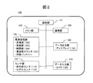
- FIG. 2 is a block diagram showing an internal configuration of the HMD 100.
- FIG. 2 is a block diagram showing an internal configuration of a battery 200.
- FIG. 2 is a block diagram showing an internal configuration of a charger 300.
- the figure which shows control of the electric power transmission between HMD and a battery (Example 2).
- FIG. 20A The figure which shows the other example of a battery internal structure.
- the figure which shows the modification of FIG. The figure which shows the structure of the charger 400 which charges the battery of the state with which HMD was mounted
- HMD glasses-type head mounted display
- the HMD is equipped with multiple batteries, and when the remaining battery level is low, the HMD is removed from the HMD and charged by the charger. The user can continue to use the HMD because the power is supplied to the HMD by switching to another standby battery while charging the battery. At this time, electric power is transmitted wirelessly (without contact) between the HMD and the battery, and between the battery and the charger, and information such as the remaining amount of the battery and the charge amount are mutually transmitted by communication.
- FIG. 1 is a diagram showing an entire configuration of a power supply system including an HMD 100, a battery 200, and a charger 300.
- the power receiving units 102a and 102b are provided in the symmetrical (vine) portion (temple portion 114) of the glasses, and two batteries 200a and 200b are mounted. Electric power is supplied from the batteries 200a and 200b to the power receiving units 102a and 102b through the power transmission and reception coils.
- two batteries are mounted in this embodiment, two or more batteries may of course be used.
- the display 119 of the HMD 100 displays a warning of the insufficient amount.
- the user removes the battery 200a from the power receiving unit 102a and inserts the battery 200a into the charging slot 311 (four slots 311a to 311d in this example) of the charger 300.
- the HMD 100 switches to the other battery 200b on standby and continues the operation.
- the charging operation from the charger 300 to the battery 200a also supplies power via the power transmission and reception coil.
- the display unit of the HMD 100 is notified of the charging completion, and the user takes out the battery 200a and attaches it to the power receiving unit 102a of the HMD 100.
- the HMD 100 is equipped with a plurality of batteries and switched alternately, the user can continue to use the HMD 100.
- the replacement work of the battery 200 with respect to the HMD 100 and the insertion work into the charger 300 are performed in a state in which the user wears the HMD 100, the following measures are taken.
- An infrared sensor 115a is installed just behind the power receiving unit 102a for mounting the battery 200 in the HMD 100 toward the outside of the temple unit. Further, the infrared sensor 115b is similarly installed in the power reception unit 102b on the opposite side.
- the user removes the battery 200a attached to the power receiving unit 102a
- the user can easily remove the battery 200a by putting a finger in the recess at the rear end of the power receiving unit 102a.
- the infrared sensor 115a near the rear end of the power receiving unit 102a detects that the hand approaches to remove the battery 200a.
- the infrared sensor 115b installed near the power reception unit 102b on the right eye side makes the user's hand approach By giving a warning that the battery to be replaced and the battery to be replaced is the battery on the left eye side instead of the right eye side, it is possible to prevent the user's erroneous operation.
- the slot number portions 312a to 312d corresponding to the respective charging slots have a convex structure in the form of numbers, and the user can touch with a finger to recognize the slot number and the orientation of the charger.
- the red LED lights up when charging of the battery is started, and the green LED lights up when charging is completed.
- the glasses-type HMD 100 can be worn on the head and detached from the head by widening the temple portion.
- Strain sensors 116a and 116b are provided at the display unit side end of the temple unit, and it is understood that the sensor is detached from the head by detecting the spread when the HMD is attached by the strain sensors 116a and 116b. If the detection signals of the strain sensors 116a and 116b do not change for a predetermined time (for example, one minute), the HMD 100 automatically enters the standby mode, and when the detection signal changes again, the HMD operation is activated. This can save the power consumption of the HMD 100.
- a camera 120 and an infrared sensor 115 c are provided on the front side of the HMD 100. Next, configurations of the HMD 100, the battery 200, and the charger 300 will be described.
- FIG. 2 is a block diagram showing an internal configuration of the HMD 100.
- the HMD 100 includes a control unit 101, a memory unit 105, a power management unit 106, a sensor unit 107, a communication unit 108, a data output unit 109, and a data input unit 110.
- the control unit 101 controls the overall operation of the HMD 100.
- the memory unit 105 stores information on the internal state of the HMD 100 and information on the storage state of the battery 200, and stores image data displayed by the HMD.
- the power management unit 106 includes a power reception unit 102, a conversion unit 103, and a restriction unit 104 for receiving power from the battery 200 in use, and supplies power to each unit in the HMD 100.
- the power receiving unit 102 includes a power receiving coil for wirelessly receiving power.
- the power management unit 106 also monitors the state of the battery 200 being used by the HMD 100, the battery 200 being charged by the charger 300, and the battery built therein.
- the frequency counter 121 detects that the battery 200 in use has been removed. Details of these operations will be described later.
- the sensor unit 107 includes an infrared sensor 115 and a strain sensor 116.
- an acceleration sensor, a gyro sensor, a magnetic sensor, a temperature sensor, an electrostatic sensor, a tactile sensor, and the like are provided as necessary.
- the communication unit 108 may include a wireless LAN or Bluetooth (registered trademark) for wireless communication with the battery 200 or the charger 300, and may have a position information acquisition function or a one-segment function by a GPS (Global Positioning System).
- the data output unit 109 includes a display 119 for displaying video and information to be provided to the user at the position of the lens unit of the glasses, a speaker (earphone) for outputting sound, a light emitting element, and the like.
- the data input unit 110 includes a camera 120 for capturing a landscape in front of the HMD 100, a microphone for inputting voice, an operation input unit from a user, and the like.
- FIG. 3 is a block diagram showing an internal configuration of the battery 200.
- the battery 200 includes a control unit 204, a communication unit 205, a memory unit 206, a storage state recognition unit 207, a storage unit 208, and a display unit 209.
- the control unit 204 controls the overall operation of the battery 200.
- the communication unit 205 includes a wireless LAN or Bluetooth (registered trademark) for wireless communication with the HMD 100 or the charger 300.
- the memory unit 206 can store information on the internal state of the battery 200 and can store image data to be displayed by the HMD 100.
- the storage state recognition unit 207 detects the remaining storage amount or the charge amount of the battery and holds the information.
- the storage unit 208 includes a storage battery unit 201 formed of a storage element, and a power transmission / reception unit 203 that transmits or receives power between the conversion unit 202, the HMD 100, and the charger 300.
- the power transmission and reception unit 203 has a power transmission and reception coil for transmitting and receiving power wirelessly.
- the display unit 209 is an LED 215 that displays the storage amount of the battery by color coding.
- the battery 200 is distinguished from 200a to 200d (the same applies to the internal elements of the battery) depending on the use state (during use with HMD, during charge with a charger).
- FIG. 4 is a block diagram showing an internal configuration of the charger 300.
- the charger 300 includes a control unit 301, a communication unit 302, a memory unit 303, a battery monitoring unit during charging 304, a display unit 305, and a power supply unit 306.
- the control unit 301 controls the overall operation of the charger 300.
- the communication unit 302 includes a wireless LAN or Bluetooth (registered trademark) for wireless communication with the HMD 100 or the battery 200. Furthermore, it may have a position information acquisition function by GPS or a one-segment function.
- the memory unit 303 can store information on the internal state of the charger 300 and information on the storage state of the battery 200, and can store image data displayed by the HMD 100.
- the battery monitoring unit 304 acquires information on the charge amount of the battery 200 being charged.
- the display unit 305 is an LED that displays the start and completion of the charging of the battery in a color-coded manner.
- the feeding power supply unit 306 includes a storage battery unit 307 for feeding power to the battery 200, a conversion unit 308, and a power transmission unit 309.
- the power transmission unit 309 has a power transmission coil for wirelessly transmitting power.
- the display unit 305 and the feeding power supply unit 306 are provided as many as the number of charging slots 311.
- the storage battery unit 307 of the feeding power supply unit 306 can be charged by an external power supply. And according to the use condition of HMD100, it uses together and uses an external power supply. For example, in the case of sitting in one place and using the HMD 100 for a long time like watching a movie, the power supply unit 306 is connected to an external power supply such as a commercial power supply and used. On the other hand, when carrying the HMD 100, the battery 200 of the HMD is charged by the charged storage battery unit 307.
- the power transmission unit / power reception unit includes a power transmission coil / power reception coil
- the communication unit includes an antenna, which is omitted for simplification in the drawings.
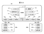
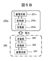
- FIGS. 5A and 5B are diagrams for explaining power transmission between the HMD 100, the battery 200, and the charger 300.
- FIG. 5A shows power transmission between the HMD 100 and the in-use batteries 200 a and b
- FIG. 5B shows power transmission between the in-charge battery 200 c and the charger 300.
- a plurality of (here, two) batteries 200a and 200b can be attached to the HMD 100, and power can be supplied from the respective batteries 200a and 200b.
- a direct current flows out from the storage battery units 201a and 201b of the battery, and is converted to an alternating current of, for example, 150 kHz by the conversion units 202a and 202b. Then, the power is transmitted from the power transmission units 203a and 203b (power transmission coils) to the HMD 100 by wireless.
- the HMD 100 includes a plurality of power receiving units 102a and 102b (power receiving coils), and receives power wirelessly transmitted, for example, at 150 kHz from the batteries 200a and 200b.
- the conversion units 103a and 103b convert the received alternating current into a predetermined direct current.
- the limiting units 104a and 104b supply DC current to the control unit 101, but limit the supplied power according to the power usage status of the load in the HMD 100. Therefore, the control unit 101 sends a control signal for power limitation to the limitation unit 104 based on the power usage status of the load, but this is omitted in the drawing.
- the usage of the plurality of batteries 200a and 200b in the HMD 100 can be set by selecting the control sequence performed by the control unit 101, such as, for example, using the one with the smaller remaining storage capacity preferentially. Also, by enabling the two-way power transmission and power conversion of the power reception units 102a and 102b and the conversion units 103a and 103b, one power reception unit, for example 102a, is always attached with the battery 200a, and the other power reception unit 102b can be set as exchange only. As a result, the battery 200 b mounted on the power receiving unit 102 b can receive power necessary for the operation of the HMD 100 and can also be set to store power in the battery 200 a. In this case, even if one hand can not be used for some reason, with the HMD 100 attached, continuous use can be performed for a long time exceeding the usage time with a single battery capacity.
- the other battery works as a power source of the HMD 100 at the time of battery replacement, so that the HMD can be used continuously even at the time of battery replacement.
- the built-in battery provided in the power management unit 106 of the HMD 100 can also be used.
- the battery capacity of the internal battery is smaller than that of the attached batteries 200a and 200b, but by making the battery capacity sufficient to operate the HMD 100 during the battery replacement time, the HMD can be used continuously even when the battery is replaced . However, if the battery is not replaced for a predetermined time, the HMD 100 itself is shut down for data preservation and the like.
- FIG. 5B shows power transmission (charging operation) from the charger 300 to the battery 200c.
- the direct current generated from the storage battery unit 307 is converted into an alternating current by the conversion unit 308, and wirelessly transmitted from the power transmission unit 309 (power transmission coil) to the battery 200c being charged.
- the power transmitted from charger 300 is received by power reception unit 203c (power reception coil) in power storage unit 208 of battery 200c, converted into direct current by conversion unit 202c, and stored in storage battery unit 201c.
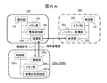
- FIG. 6A and 6B are diagrams for explaining communication among the HMD 100, the battery 200, and the charger 300.
- FIG. 6A shows communication related to the in-use battery 200a (200b)
- FIG. 6B shows communication related to the in-charge battery 200c.
- the communication unit 108 of the HMD 100 performs wireless communication with the communication unit 205a of the battery 200a (200b) in use, and the remaining charge amount of the battery obtained by the storage state recognition unit 207a of the batteries 200a and 200b in use.
- the power management unit 106 of the HMD 100 acquires the information of Furthermore, the communication unit 108 of the HMD 100 performs wireless communication with the communication unit 302 of the charger 300, and transmits information on the remaining storage amount of the in-use batteries 200a and 200b obtained by the HMD 100.
- the communication unit 108 of the HMD 100 transmits a control instruction to stop power transmission or the like from the control unit 101 to the in-use batteries 200 a and b based on the power usage status of the load in the HMD 100.
- the communication unit 302 of the charger 300 performs wireless communication with the communication unit 205c of the battery 200c being charged, and the information (charge amount) of the storage state of the battery 200c obtained by the storage state recognition unit 207 of the battery 200c. While the battery charger 300 is charging. Furthermore, the communication unit 108 of the HMD 100 performs wireless communication with the communication unit 302 of the charger 300, and the power management unit 106 of the HMD 100 acquires information on the state of charge of the battery 200c being charged.
- the communication unit 108 of the HMD 100 transmits a control instruction such as charge start / stop from the control unit 101 to the charger 300 based on the remaining storage amount of the batteries 200a and 200b in use and the power usage status of the load in the HMD 100. Accordingly, the charger 300 controls the battery 200c being charged.
- the HMD 100 and the charger 300 mutually communicate the remaining storage amount of the batteries 200a and 200b in use and the storage state information of the battery 200c during charging, and store them in the respective memory units 105 and 303.
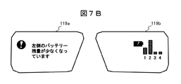
- FIG. 7A and 7B show display examples of the battery status by the display 119 of the HMD 100.
- FIG. 7A and 7B show display examples of the battery status by the display 119 of the HMD 100.
- FIG. 7A is an example in which various function menus of the HMD are displayed on the display 119.
- the user selects the battery-related menu 701 from the menu palette. In order to check the status of the battery, this menu 701 is activated or always activated.
- FIG. 7B is an example in which the status of the battery is displayed on the display 119.
- a warning prompting battery replacement is displayed on the left display 119a, and information on the charge amount of the battery in each charging slot is displayed on the right display 119b.
- a warning "Remaining battery level on the left side is low” is automatically displayed on the display 119a of the left eye of the HMD 100, prompting the user to replace the battery.
- display is made on the side of the battery whose battery level is low. When this is displayed, the user will replace the battery on the left.
- the amount of battery charge during charging of each slot is displayed by a bar on the display 119b on the opposite side, which is the opposite side.
- the charge amount of the battery of slot number 2 is maximum, and the number and bar of slot 2 blink and are displayed.
- the number 312b (number 2) of the battery charging slot 311b blinks with a green LED, and the LED of the battery 200 also blinks with green.
- the user may take out the battery being charged in the charging slot 311 b and attach it to the HMD.
- the user can replenish the power by battery replacement while wearing the HMD 100, and can continue the use without interrupting the use of the HMD.
- the battery when replacing a battery of a device, if the battery can be replaced while using the device, it is called "hot-swappable".
- the power transmission from the battery 200 to the HMD 100 and the power transmission from the charger 300 to the battery 200 are wireless power transmission of a close distance, it is possible to easily transmit necessary power.
- the battery 200 has a structure in which the metal terminal is not exposed to the outside, there is no concern about corrosion of the terminal due to sweat or a short circuit between the terminals when replacing the battery, even if the HMD is mounted on the user's head.
- FIG. 8 is a diagram showing data transmission between the power supply system of this embodiment and the cloud 600.
- the power supply system includes the HMD 100, a battery 200a in use (during installation) in the HMD, a charger 300, and a battery 200c being charged by the charger.
- Data transmission between the HMD 100 and the cloud 600 is performed by downloading image data or the like from the cloud 600 and viewing the image on the HMD 100 (reference numeral 601 a), and the image data acquired by the data input unit 110 (camera 120) of the HMD 100 to the cloud 600. There is a case of uploading to (symbol 601 b). In either case, since direct transmission is performed between the HMD 100 and the cloud 600, it takes time to transmit a large amount of data such as a movie and there is a concern that the capacity of the battery may run short. Therefore, in the configuration of the present embodiment, data transmission is performed using the charging time via the battery 200 being charged.
- the communication unit 302 of the charger 300 downloads data from the cloud 600 and stores the data in the memory 206 c of the battery 200 c being charged.
- the data stored in the memory unit 206a of the in-use battery 200a is read out and viewed (path 602a).
- the data generated by the HMD 100 is stored in the memory unit 206 of the in-use battery 200 a using the memory unit 105 as a buffer.
- the stored data is read from the memory unit 206c of the battery 200c and uploaded to the cloud 600 via the communication unit 302 of the charger 300 (path 602b).
- the HMD 100 performs data transmission with the cloud 600 using the memory unit of the battery 200 being charged, so that it is possible to efficiently transmit large-capacity data.
- FIG. 9 is a diagram showing control of power transfer between the HMD and the battery.
- a plurality of batteries 200a and 200b are attached to the HMD 100, and a configuration for switching these is shown.
- the limiting units 104a and 104b have a backflow preventing diode D, a current detection resistor R, a MOS field effect transistor (MOSFET) M1, and a storage capacitor C in power lines supplied from the respective batteries 200a and b.
- the control unit 101 turns off the power received from the battery 200 by performing ON / OFF control of the MOSFET (M1).
- the power management units 106 a and 106 b of the HMD 100 have amplifiers and frequency counters 121 a and 121 b, and detect that the battery 200 has been removed from the HMD 100.
- the resonant frequency of the wireless power supply in the power receiving units 102a and 102b fluctuates, so that detection can be made by monitoring the resonant frequency with the frequency counter 121.
- MOS field effect transistors (MOSFETs) M2a and b are provided between the storage battery units 201a and 201b in the storage units 208a and 208b and the conversion units 202a and 202b.
- MOSFETs MOS field effect transistors
- the control units 204a and 204b By controlling the MOSFET (M2) by the control units 204a and 204b, the current flowing out of the storage battery units 201a and 201b to the conversion units 202a and 202b is limited. Further, the remaining storage amount of the battery 200 is determined by measuring the voltage VB across the terminals of the storage battery units 201a and 201b by the storage state recognition units 207a and 207b.
- the procedure for replacing the battery being used in the HMD will be described.
- FIG. 10 is a flowchart showing a process of removing the battery from the HMD due to a shortage of the remaining charge amount of the battery in use.
- the battery 200 in use reads the inter-terminal voltage VB (remaining storage amount) of the storage battery unit 201 by the storage state recognition unit 207 and transmits it to the HMD 100 by communication with the HMD 100 (S101).
- the HMD 100 compares the received voltage VB with a preset first threshold Vth1 (S102). If the voltage VB is larger than the threshold value Vth1, the battery can be used continuously, so the process returns to S101. However, when the voltage VB becomes smaller than the threshold value Vth1, a warning such as "the battery is low" is displayed on the display 119 of the HMD 100 (S103). Specifically, as shown in FIG. 7B, the display 119a is displayed on the battery side where the remaining storage amount has decreased.
- the battery 200 reads and communicates the inter-terminal voltage VB (S104), and the HMD 100 compares the received voltage VB with a second threshold Vth2 set in advance (where Vth2 ⁇ Vth1) (S105). While the voltage VB is larger than the threshold value Vth2, the battery can be used continuously, so the process returns to S104. However, when the voltage VB becomes smaller than the threshold value Vth2, the battery is removed.
- the HMD 100 turns off the MOSFET (M1) of the limiting unit 104 (S106) to prevent reverse current to the battery 200 side. Furthermore, it instructs the battery 200 in use to turn off the MOSFET (M2), and the current flow from the storage battery unit 201 is stopped (S107). At this stage, a warning “Please replace the battery” is displayed on the side of the display 119 of the HMD 100 on which the battery with the remaining electric energy stored has decreased (S108).
- the user removes the battery 200 from the HMD 100 (S109), and the communication between the battery 200 and the HMD 100 is turned off (S110).
- one third threshold value Vth3 having a margin of the remaining power of, for example, about 10% is set, and the user can It is also possible to shift to battery replacement work while battery power remains.
- FIG. 11 is a flowchart showing a process of switching to a standby battery when the remaining storage amount of the battery in use is insufficient.
- the case of switching from the battery 200a on the left to the battery 200b on the right will be described as an example.
- the inter-terminal voltage VB (remaining storage amount) of the storage battery unit 201a of the battery 200a in use is read and compared with the first threshold Vth1 and the second threshold Vth2 (S201 to S205). This is similar to S101 to S105 of FIG. When the voltage VB becomes smaller than the threshold value Vth2 (Yes in S205), switching from the battery 200a to the battery 200b is performed.
- the control unit 101 of the HMD 100 turns off the MOSFET (M1a) of the limiting unit 104a on the side of the battery 200a in use, and turns off the MOSFET (M2a) on the battery 200a in use, Stop the current flow (S206).
- the MOSFET (M1b) of the limiting unit 104b on the side of the battery 200b on standby is turned on, and the MOSFET (M2b) on the battery 200b on standby is turned on to start current flow from the storage battery unit 201b (S207 ).
- the power reception system is switched from the battery 200a to the battery 200b.
- the power of the HMD 100 is covered by the power stored in the capacitor Ca of the limiting unit 104a and the built-in battery of the HMD 100. Therefore, the switching of the battery does not interrupt the operation of the HMD 100.
- a warning “Please replace the battery” is displayed on the display 119a on the left side of the HMD 100 (S208).
- the user removes the battery 200a (S209), and the communication between the battery 200a and the HMD 100 is turned off (S210).
- FIG. 12 is a flowchart showing processing when the battery is removed from the HMD. It describes the process to shut off the power supply when the battery is removed for some reason as well as when the battery is replaced.
- the HMD 100 monitors the resonance frequency FR of the power receiving unit 102 (power receiving coil) by the frequency counter 121 of the power management unit 106 (S301).
- the resonance frequency FR fluctuates.
- the control unit 101 of the HMD 100 turns off the MOSFET (M1) of the restriction unit 104 (S303).
- the communication unit 108 of the HMD 100 communicates with the battery 200, the MOSFET (M2) of the battery 200 is turned off, and the current flow from the storage battery unit 201 is stopped (S304).
- a warning "Battery removed" is displayed (S305).
- the user in battery replacement of the HMD 100, the user can continue to use the HMD 100 without interrupting the operation of the HMD 100, and the hot swap function can be realized.
- the structure of a battery 200 suitable for mounting on the HMD 100 or the charger 300 will be described.
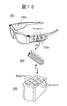
- FIG. 13 is a diagram showing an operation of attaching the battery 200 to the HMD 100 and the charger 300.
- a plurality of magnets 111a, 111b, and 111c are attached to the battery mounting surface of the power receiving unit 102.
- a plurality of magnets are attached here, one magnet may be attached.
- ferrite of the same shape is attached to the battery 200. These magnets and ferrites are for alignment of the power transmission and reception coils between the HMD 100 and the battery 200 and magnetic field leakage reduction.
- magnets of the same shape are attached, and alignment of the transmitting and receiving coils between the charger 300 and the battery 200 and magnetic field leakage are reduced.
- FIG. 14 is a diagram showing an example of a power system circuit in the battery 200.
- the battery 200 includes a storage battery unit 201, a conversion unit 202, and a power transmission and reception unit 203.
- the conversion unit 202 is a two-way converter of direct current / AC conversion, and the coil 203 ⁇ / b> L in the power transmission and reception unit 203 is used for both power transmission and power reception.
- the structure of the battery will be described in detail.
- FIG. 15 is a view showing an example of the internal structure of the battery 200, where (a) is a view seen through the lid of the case 214 and (b) is a cross-sectional view taken along ⁇ - ⁇ '.
- (b) for example, in the resinous case 214, the storage battery unit 201, the electronic substrate 213, the ferrite plate 211, and the ferrite cylinders 212a, 212b, 212c and the coil 203L are mounted on the ferrite plate 211. It is done.
- FIG. 16 is a view showing a state in which the battery 200 is attached to the HMD 100.
- FIG. (A) is a figure which attached the battery to HMD
- (b) and (c) are beta-beta 'sectional views.
- the temple portion 114 of the HMD 100 is shaped to cover all the upper and lower surfaces of the case 214 of the battery in (b), while retaining a part of the lower portion of the case 214 in (c).
- the ferrites 212 and 211 of the battery 200 can be attracted by the magnet 111 of the HMD 100, and the battery 200 can be fixed.
- the magnet 111 is disposed on the ferrite plate 113 together with the coil 102L in the power receiving unit 102 of the HMD 100.
- the magnet 111 and the ferrite cylinder 212 of the battery 200 the alignment of the coil 102L of the HMD 100 and the coil 203L of the battery 200 can be performed. Further, at the time of power transmission, the magnetic field generated by the coil 203L passes through the ferrite plates 211 and 113, the magnet 111, and the ferrite cylinder 212, so magnetic field leakage can be reduced.
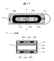
- FIG. 17 is a view showing another example of the internal structure of the battery 200, wherein (a) is a view through the lid of the case 214, and (b) is a cross-sectional view taken along ⁇ - ⁇ '.
- two sets of the coil 203L and the ferrites 211 and 212 are provided on both sides in the case 214 of the battery 200.
- the coil 203L closer to the power receiving unit 102 of the HMD 100 and the ferrites 211 and 212 can be used. Therefore, the user can mount the battery 200 without worrying about the mounting side.
- FIG. 18 is a view showing a modification of FIG.
- ends of two sets of coils 203L arranged on both sides in the case 214 are connected to constitute one coil.
- one coil is bent at substantially the center and arranged on both sides in the case 214. Also in this case, since the configuration of the battery 200 is symmetrical, mounting to the HMD 100 and installation to the charger 300 are facilitated.
- FIG. 19 is a diagram showing a configuration of a charger 400 for charging the battery 200 in a state of being attached to the HMD 100.
- the operation of the charger 400 is the same as that of the charger 300 of the first embodiment, but this figure is for describing the structure of the charging unit, and other things such as the electronic board in the charger are omitted.
- the battery 200 has the structure shown in FIG. 17, and the HMD 100 mounted thereon is shown installed in the charger 400.
- the cross-sectional shape of the temple portion 114 of the HMD 100 is the case of FIG. (A) is a view seen from above, (b) is a ⁇ - ⁇ 'sectional view, (c) is a partially enlarged view.
- the shape of the charger 400 includes a raised portion 401 in the middle and charged portions 402a and 402b raised on both sides thereof, and the temple portion 114 of the HMD 100 is housed between 401 and 402a, b.
- a power transmission coil 403L for battery charging and a magnet 411 are disposed on the ferrite plate 413.
- the coil 203L on the left side of the drawing faces the coil 403L of the charger 400.
- the coil 203 L of the battery 200 is a common coil for power transmission and reception, and can charge the battery 200 from the coil 403 L of the charger 400. Also, due to the attraction between the magnet 411 of the charger 400 and the ferrite cylinder 212 of the battery 200, the coil 403L of the charger 400 and the coil 203L of the battery 200 are automatically aligned, and sufficient power transmission efficiency is always achieved. can get.
- the magnetic field generated by the coil 403L passes through the ferrite plates 413 and 211, the ferrite cylinder 212, and the magnet 411, so that the magnetic field leakage can be reduced.
- the battery 200 is charged only by installing the HMD 100 in the charger 400 overnight. Further, with the configuration shown in FIG. 8, necessary data such as a movie can be downloaded from the cloud 600.
- the battery 200 can be easily attached to the HMD 100 and the charger 300, and the power transmission efficiency is improved. Further, according to the configuration of FIG. 19, it is possible to easily charge the battery 200 in a state of being attached to the HMD 100.
- FIG. 20A is a diagram illustrating the configuration of a power feeding system according to a fourth embodiment, in which power can be fed to the HMD from the battery and the charger.
- power is supplied to the HMD 100 from the two batteries 200a and 200b and also from the two chargers 500a and 500b other than the batteries.
- two chargers are used here, the number is arbitrary, and a plurality of chargers may be integrated.
- chargers 500c and 500d also have storage battery unit 501, conversion unit 502, and power transmission unit 503, and similarly transmit power wirelessly from power transmission unit 503 to HMD 100.
- the HMD 100 has four power receiving units 102a, 102b, 102c, and 102d, and uses the power receiving system of the power receiving units 102a and 102b from the batteries 200a and 200b, and uses the power receiving system of the power receiving units 102c and 102d from the charger 500. .
- the power receiving unit 102 receives power
- the converting unit 103 converts the power into a predetermined direct current, and the power is based on the power usage status of the load such as the communication unit 108 controlled by the control unit 101. , Limited by the restriction unit 104.
- conversion unit 103 and power reception unit 102 can charge batteries 200 a and 200 b with the power supplied from chargers 500 c and 500 d.
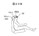
- FIG. 20B is a diagram showing a specific application example of the power supply system of FIG. 20A.
- the batteries 200a and 200b are attached to the temple portion of the HMD.
- the power transmission units 503c and 503d of the chargers 500c and 500d are disposed, for example, in a headrest of a seat.
- the power reception units 102c and 102d of the HMD 100 that receive power from the power transmission units 503c and 503d are disposed on the left and right in the temple unit close to the headrest, for example, the modern unit.
- the power supply from the charger 500 can be prioritized and used, and the battery 200 can also be charged.
- power supply from the battery 200 is switched.
- a single battery can be used continuously for a long time exceeding the usage time at the battery capacity.
- the configuration of the power supply has been described by taking the glasses-type head mounted display (HMD), but the present invention is not limited to this, and can be applied to other wearable devices as well. Needless to say.
- HMD glasses-type head mounted display
- 100 head mounted display (HMD), 101: control unit, 102: power reception unit, 102L: coil, 103: conversion unit, 104: restriction unit, 105: memory unit, 106: power management unit, 107: sensor unit, 108 : Communication unit, 109: Data output unit, 110: Data input unit, 111: Magnet, 113: Ferrite plate, 114: Temple unit, 115: Infrared sensor, 116: Strain sensor, 119: Display, 120: Camera, 121: Frequency counter, 200: battery, 201: storage battery unit, 202: conversion unit, 203: power transmission / reception unit, 203L: coil, 204: control unit, 205: communication unit, 206: memory unit, 207: storage state recognition unit, 208: storage unit , 209: display part, 211: ferrite plate, 212: ferrite cylinder, 213: electronic substrate, 214: case, 215: LED, 300: charger, 301: control unit, 302: communication unit, 303: memory unit
Landscapes
- Engineering & Computer Science (AREA)
- Power Engineering (AREA)
- Computer Networks & Wireless Communication (AREA)
- Physics & Mathematics (AREA)
- Chemical & Material Sciences (AREA)
- General Chemical & Material Sciences (AREA)
- Electrochemistry (AREA)
- Chemical Kinetics & Catalysis (AREA)
- General Physics & Mathematics (AREA)
- Optics & Photonics (AREA)
- Manufacturing & Machinery (AREA)
- Emergency Management (AREA)
- Business, Economics & Management (AREA)
- Charge And Discharge Circuits For Batteries Or The Like (AREA)
Abstract
HMD100は、第1、第2のバッテリー200a,bを装着し、該第1、第2のバッテリーから無線伝送により電力を受電する複数の受電部102a,bと、第1、第2のバッテリーの状態を監視する電源管理部106と、第1、第2のバッテリーとの間で無線通信を行う通信部108と、複数の受電部にて受電した電力を制限する複数の制限部104a,bと、を備える。制御部101は、装置内の負荷の使用電力状況に応じ、制限部を介して負荷に対して供給する電力を制限し、電源管理部は、通信部を介して第1、第2のバッテリーの残存蓄電量の情報を取得して、取得した情報をディスプレイ119に表示する。これにより、HMDを装着したままで装置駆動に必要な電力の補給ができ、HMDの継続使用が可能となる。
Description
本発明は、ヘッドマウントディスプレイ(以下、HMD)などのウェアラブル装置への非接触給電技術に関する。
ユーザが身体に装着して使用するウェアラブル装置への非接触給電技術として、以下の技術が知られている。
特許文献1には、可変焦点レンズを有する電子眼鏡及びその充電装置に関し、電子眼鏡のモダン部に充電装置を嵌め込んで、充電装置の送電コイルから電子眼鏡の受電コイルに電磁誘導にて電力を供給して、電子眼鏡の駆動用電池を充電する構成が開示される。
特許文献2には、ユーザの眼前に配置される眼前部を温める加熱部を備えるウェアラブル装置に関し、眼前部の周囲に巻かれた電線が発熱することで眼前部を温めるとともに、前記電線は、外部の送電コイルから電力の供給を非接触で受電する受電コイルである構成が開示される。
特許文献3には、二次電池モジュールから電子デバイス(例えば眼鏡型デバイス)への給電システムに関し、二次電池モジュールのベルト部には、可撓性を有する二次電池と、非接触電力伝送を行う送電部と、可撓性を有する熱電発電装置を収納し、二次電池モジュールの送電部から、電子デバイスが有する受電部に非接触電力伝送にて送電する構成が開示される。
近年のHMDは、ウェアラブルコンピュータ、あるいはスマートフォンやタブレットのような役割を果たすようになっている。また、メガネ型の透過型HMDは拡張現実(AR:Augmented Reality)のコアデバイスとして、没入型HMDは仮想現実(VR:Virtual Reality)のコアデバイスとして重要視されている。HMDを使って映画やゲームを楽しんだりする場合もある。
しかしながら、HMDの高機能化に伴い消費電力が増加するため、従来の搭載バッテリー容量では使用可能時間が不足し、HMDを装着したままで継続使用することができなくなる。途中でHMDを外部電源にケーブルで接続して充電する、あるいはHMDの使用を中断してバッテリーを充電するなどの方法で対処せねばならず、ユーザにとって煩わしさを感じるものとなる。HMDを装着したままで継続使用するには、搭載バッテリーの容量を増加すればよいが、それに伴って重量が増加してしまう。特にメガネ型HMDは通常のメガネ同様、ユーザの耳や鼻に機器の重量がかかるため、装着感を損なわないように重量増加は可能な限り抑制しなければならない。また、HMDも携帯端末同様、小型、薄型化が進んだ反面、充電時あるいは使用中のケーブル接続は煩わしく、ユーザから簡易な充電方式の要求が高まっている。このように、装着したままで継続使用が可能であること、ケーブル接続の煩わしさの解消は、常に身に着けて使用するウェアラブル装置の重要な課題である。
前記特許文献1では、電子眼鏡の駆動用電池を充電するために、ユーザは電子眼鏡のモダン部に携帯型充電装置を嵌め込む操作を行うことになるが、携帯型充電装置の取り付け、あるいは取り外しの際に電子眼鏡が動いてしまい、あるいは一時的に電子眼鏡を頭部から取り外さざるを得ず、一時的に電子眼鏡の使用が中断することになる。すなわち、ユーザが電子眼鏡を装着したままで継続使用することは困難と思われる。なお特許文献1には、携帯型充電器を電子眼鏡のモダン部に取り付けたままで外部電源に接続して充電する方式も記載されるが、ケーブル接続の煩わしさの課題が残る。また、携帯型充電装置は外部端子によって充電器に接続するため、外部に露出する端子を有しており、頭部に装着使用する際、汗による短絡や端子の腐食などの懸念がある。
前記特許文献2では、ウェアラブル装置の眼前部の周囲に巻かれた電線が受電コイルとなり、外部の送電コイルから電力の供給を非接触で受電することが記載されている。その際、外部の送電コイルから所望の電力の供給を受けるためには、送電コイルと受電コイルの距離が近接していなければならない。これは、電力伝送時に周囲への電波漏洩を許容値以内に抑えるためである。特許文献2に記載されるように、電子眼鏡を充電台などに載置して送電コイルと受電コイルが近接している場合は所望の電力伝送が可能である。しかし、ユーザがウェアラブル装置を装着使用している状態では、外部の送電コイルを眼前部(受電コイルの位置)に近接させなければならず、ウェアラブル装置を使用するユーザの視野の妨げになる。すなわち、ウェアラブル装置をユーザが装着した状態では、十分な電力を供給できないことが予想される。
前記特許文献3では、電子デバイス(眼鏡型デバイス)は、腰部に装着するベルト状の二次電池モジュールから非接触で電力を受電する構成である。この場合も、ユーザの腰部から頭部までの距離を考慮すると、HMDなどの眼鏡型デバイスの消費電力を供給するのは困難であることが予想される。また特許文献3には、二次電池は、端子部からケーブルを介して充電することもできるとの記載があるが、前述のように、ケーブルを介しての充電はユーザにとって煩わしいものとなる。
本発明の目的は、上記従来技術の課題を鑑み、ウェアラブル装置を装着使用した状態で装置駆動に必要な電力を補給でき、ユーザにとって使用時の煩わしさの少ないウェアラブル装置を提供することにある。
本発明の一例を挙げるならば、ウェアラブル装置は、少なくとも第1、第2のバッテリーを装着し、該第1、第2のバッテリーから無線伝送により電力を受電する複数の受電部と、装着している前記第1、第2のバッテリーの状態を監視する電源管理部と、装着している前記第1、第2のバッテリーとの間で無線通信を行う通信部と、ユーザに情報を提供するディスプレイと、前記複数の受電部にて受電した電力を制限する複数の制限部と、前記受電部、前記電源管理部、前記通信部、前記ディスプレイ、および前記制限部を制御する制御部と、を備える。前記制御部は、前記ウェアラブル装置内の負荷の使用電力状況に応じ、前記制限部を介して負荷に対して供給する電力を制限し、前記電源管理部は、前記通信部を介して装着している前記第1、第2のバッテリーの残存蓄電量の情報を取得して、取得した残存蓄電量の情報を前記ディスプレイに表示することを特徴とする。
さらに、前記複数の制限部は、前記第1、第2のバッテリー側への逆方向電流を防止する機能を有し、前記電源管理部は、使用中の前記第1のバッテリーの残存蓄電量がしきい値より小さいと判定したとき、前記制御部は前記制限部の逆方向電流防止機能を制御して、使用中の前記第1のバッテリーから待機している前記第2のバッテリーへの受電系統の切り替えを行うとともに、ユーザに対し使用中の前記第1のバッテリーの交換を促す警告を前記ディスプレイに表示する。
本発明のバッテリーは、ウェアラブル装置に装着して電力を供給するとともに充電器で充電可能であって、電力を蓄電する蓄電池部と、無線伝送により、前記蓄電池部から前記ウェアラブル装置に電力を送電するとともに、前記蓄電池部を充電するために前記充電器から電力を受電する送受電部と、前記蓄電池部と前記送受電部の間で、直流電流と交流電流との変換を行う変換部と、前記蓄電池部の残存蓄電量あるいは蓄電状態情報を検知して保持する蓄電状態認識部と、前記ウェアラブル装置および前記充電器との間で無線通信を行う通信部と、前記送受電部、前記蓄電状態認識部、および前記通信部を制御する制御部と、を備え、前記蓄電状態認識部は前記通信部を介し、前記ウェアラブル装置に対して前記蓄電池部の残存蓄電量の情報を送信するとともに、前記充電器に対して前記蓄電池部の蓄電状態情報を送信し、前記制御部は前記通信部を介し、前記ウェアラブル装置から制御命令を受けると、前記蓄電池部から前記ウェアラブル装置への電力伝送を止めることを特徴とする。
さらに本発明の給電システムは、ウェアラブル装置とこれに給電するバッテリー、およびバッテリーを充電する充電器で構成される。前記ウェアラブル装置は、少なくとも第1、第2のバッテリーを装着し、該第1、第2のバッテリーから無線伝送により電力を受電する複数の受電部と、装着している前記第1、第2のバッテリーと前記充電器で充電中の第3のバッテリーの状態を監視する電源管理部と、装着している前記第1、第2のバッテリーおよび前記充電器との間で無線通信を行う通信部と、ユーザに情報を提供するディスプレイと、を備える。前記第1~第3のバッテリーは、電力を蓄電する第1の蓄電池部と、無線伝送により、前記第1の蓄電池部から前記ウェアラブル装置に電力を送電するとともに、前記第1の蓄電池部を充電するために前記充電器から電力を受電する送受電部と、前記第1の蓄電池部の残存蓄電量あるいは充電中の蓄電状態情報を検知して保持する蓄電状態認識部と、前記ウェアラブル装置および前記充電器との間で無線通信を行う通信部と、を備える。前記充電器は、電力を蓄電する第2の蓄電池部と、無線伝送により、前記第2の蓄電池部から充電中の前記第3のバッテリーに電力を送電する送電部と、充電中の前記第3のバッテリーの蓄電状態情報を取得する充電中バッテリー監視部と、前記ウェアラブル装置および前記第3のバッテリーとの間で無線通信を行う通信部と、を備える。前記ウェアラブル装置は、装着している前記第1、第2のバッテリーから取得した残存蓄電量の情報と、前記充電器から取得した充電中の前記第3のバッテリーの蓄電状態情報を前記ディスプレイに表示し、使用中の前記第1のバッテリーの残存蓄電量がしきい値より小さいと判定したとき、使用中の前記第1のバッテリーから待機している前記第2のバッテリーへの受電系統の切り替えを行うとともに、ユーザに対し使用中の前記第1のバッテリーの交換を促す警告を前記ディスプレイに表示することを特徴とする。
本発明によれば、ユーザがウェアラブル装置を装着したままで必要な電力の補給ができ、装置の継続使用が可能となる。例えば、ユーザが長時間の映画を鑑賞する場合でも、搭載するバッテリーを増加することにより装着感を損なうことなく、またウェアラブル装置の端子から外部電源に電力供給用のケーブルを接続する煩わしさもなく、使い勝手が向上する。
以下、本発明の実施の形態について、図面を用いて詳細に説明する。ただし、本発明は以下に示す実施の形態の記載内容に限定して解釈されるものではない。本発明の思想ないし趣旨から逸脱しない範囲で、その具体的構成を変更し得ることは当業者であれば容易に理解される。以下に説明する発明の構成において、同一部分又は同様な機能を有する部分には同一の符号を異なる図面間で共通して用い、重複する説明は省略することがある。
実施例1では、本発明におけるウェアラブル装置への電力供給の基本構成について説明する。ユーザが身体に装着して使用するウェアラブル装置の例として、メガネ型のヘッドマウントディスプレイ(以下、HMD)を取り上げる。HMDは複数のバッテリーを装着しており、使用中のバッテリーの残量が不足するとHMDから取り外して充電器にて充電する。バッテリー充電中は待機している他のバッテリーに切り替えてHMDへ電力を供給するので、ユーザはHMDを継続して使用することができる。その際、HMDとバッテリー、及びバッテリーと充電器の間では、電力を無線(非接触)で伝送するとともに、バッテリーの残量や充電量等の情報を互いに通信にて伝送する構成としている。
図1は、HMD100、バッテリー200および充電器300からなる給電システムの全体構成を示す図である。まず、基本操作を説明する。メガネ型のHMD100には、メガネの左右対称の「つる」の部分(テンプル部114)に受電部102a,102bがあり、2個のバッテリー200a,200bを装着する。バッテリー200a,200bから受電部102a,102bへは送受電コイルを介して電力を供給する。ここではバッテリーを2個装着する構成としたが、もちろん2個以上の複数個であっても良い。
HMD100を使用することで一方のバッテリー200aの残量が不足すると、HMD100のディスプレイ119に残量不足の警告を表示する。ユーザは受電部102aからバッテリー200aを外して、充電器300の充電スロット311(この例では4個のスロット311a~311d)に挿入する。その間HMD100は、待機している他方のバッテリー200bに切り替えて動作を継続する。
充電器300からバッテリー200aへの充電動作も、送受電コイルを介して電力を供給する。バッテリー200aの充電が完了するとHMD100の表示部に充電完了を知らせ、ユーザはバッテリー200aを取り出してHMD100の受電部102aに装着する。このように、HMD100には複数のバッテリーを装着し、交互に切り替えて使用するので、ユーザはHMD100を継続して使用できる。ただし、HMD100に対するバッテリー200の交換作業と、充電器300への挿入作業はユーザがHMD100を装着した状態で行うため、以下の工夫が施されている。
HMD100にてバッテリー200を装着する受電部102aのすぐ後ろには、テンプル部の外側に向けて赤外線センサ115aが設置されている。また、反対側の受電部102bにおいても同様に赤外線センサ115bが設置されている。ユーザが受電部102aに装着されているバッテリー200aを外すときは、受電部102aの後端にある窪みに指を入れてバッテリー200aを容易に外すことができる。そのとき、受電部102aの後端近傍にある赤外線センサ115aは、バッテリー200aを外すために手を近づいたことを検知する。もしもユーザが誤って、バッテリー200a(左目側)ではなく反対側のバッテリー200b(右目側)を外そうとすると、右目側の受電部102bの近傍に設置した赤外線センサ115bがユーザの手の接近を検知し、今交換すべきバッテリーは右目側ではなく左目側のバッテリーであると警告を発することで、ユーザの誤操作を防止することができる。
次にユーザは、取り外したバッテリー200aを、充電器300の複数の充電スロット311a~311dのいずれかに挿入設置する。各充電スロットに対応するスロット番号部分312a~312dは番号の形で凸構造をしており、ユーザは指で触れてスロット番号や充電器の向きを認識できる。なお、スロット番号部分312はバッテリーの充電が開始されると赤色のLEDが点灯し、充電が完了すると緑色のLEDが点灯する。充電スロット311に挿入されたバッテリー200においても同様で、充電が開始されると赤色のLED215が点灯し、充電が完了すると緑色のLED215が点灯する。
また、メガネ型HMD100はテンプル部を広げることにより、頭部への装着および頭部からの脱着が可能である。テンプル部の表示部側の端にはひずみセンサ116a,116bが備えられており、HMD装着時の広がりをひずみセンサ116a,116bにより検知することで、頭部から脱着したことがわかる。ひずみセンサ116a,116bの検出信号に所定時間(例えば1分間)変化がなければ、HMD100は自動的にスタンバイモードになり、再び検出信号が変化すると、HMD動作を起動する。これによりHMD100の消費電力を節約できる。HMD100の正面側には、カメラ120と赤外線センサ115cが備えられている。
次に、HMD100、バッテリー200、充電器300のそれぞれの構成を説明する。
次に、HMD100、バッテリー200、充電器300のそれぞれの構成を説明する。
図2は、HMD100の内部構成を示すブロック図である。HMD100は、制御部101、メモリ部105、電源管理部106、センサ部107、通信部108、データ出力部109、データ入力部110より構成される。制御部101はHMD100の全体の動作を制御する。
メモリ部105は、HMD100の内部状態の情報やバッテリー200の蓄電状態の情報を記憶し、またHMDで表示する画像データを保存する。電源管理部106は、使用中のバッテリー200から電力を受電するための、受電部102、変換部103、制限部104を備え、HMD100内の各部に電力を供給する。受電部102は、無線で電力を受電するための受電コイルを有する。また電源管理部106は、HMD100で使用中のバッテリー200、充電器300で充電中のバッテリー200、また内蔵するバッテリーの状態を監視する。周波数カウンタ121は、使用中のバッテリー200が外れたことを検知する。これらの動作の詳細は後述する。
センサ部107は、赤外線センサ115、ひずみセンサ116を備えているが、その他に加速度センサ、ジャイロセンサ、磁気センサ、温度センサ、静電センサ、触覚センサなど、必要に応じて備えるものとする。通信部108は、バッテリー200や充電器300と無線通信するための無線LANやBluetooth(登録商標)を備え、またGPS(Global Positioning System)による位置情報取得機能やワンセグ機能を備えていても良い。
データ出力部109は、メガネのレンズ部の位置にユーザに提供する映像や情報を表示するディスプレイ119と、音声を出力するスピーカ(イヤホン)、発光素子などで構成される。データ入力部110は、HMD100の前方の風景を撮影するカメラ120や、音声を入力するマイク、ユーザからの操作入力部などで構成される。
図3は、バッテリー200の内部構成を示すブロック図である。バッテリー200は、制御部204、通信部205、メモリ部206、蓄電状態認識部207、蓄電部208、表示部209より構成される。制御部204は、バッテリー200の全体の動作を制御する。
通信部205は、HMD100や充電器300と無線通信するための無線LANやBluetooth(登録商標)を備える。メモリ部206はバッテリー200の内部状態の情報を記憶し、またHMD100で表示する画像データを保存することができる。
蓄電状態認識部207は、当該バッテリーの残存蓄電量、あるいは充電量を検知してその情報を保持している。蓄電部208は、蓄電素子からなる蓄電池部201と、変換部202、HMD100や充電器300との間で電力を送電または受電する送受電部203を備える。送受電部203は、電力を無線で送受電するための送受電コイルを有する。表示部209は、当該バッテリーの蓄電量を色分けして表示するLED215である。
なお、以下の説明では、バッテリー200はその使用状態(HMDで使用中、充電器で充電中)に応じて、200a~200d(バッテリーの内部要素についても同様)と区別表記する。
図4は、充電器300の内部構成を示すブロック図である。充電器300は、制御部301、通信部302、メモリ部303、充電中バッテリー監視部304、表示部305、給電電源部306より構成される。制御部301は、充電器300の全体の動作を制御する。
通信部302は、HMD100やバッテリー200と無線通信するための無線LANやBluetooth(登録商標)を備える。さらに、GPSによる位置情報取得機能やワンセグ機能を備えていても良い。
メモリ部303は充電器300の内部状態の情報やバッテリー200の蓄電状態の情報を記憶し、またHMD100で表示する画像データを保存することができる。
充電中バッテリー監視部304は、充電中のバッテリー200の充電量の情報を取得する。表示部305は、バッテリーの充電の開始と完了を色分けして表示するLEDである。
給電電源部306は、バッテリー200へ給電する蓄電池部307、変換部308、送電部309を備える。送電部309は、電力を無線送電するための送電コイルを有する。なお、表示部305と給電電源部306は、充電スロット311の数だけ備えている。
ここで給電電源部306の蓄電池部307は、外部電源により充電可能である。そして、HMD100の使用状況に応じて外部電源を併用して用いる。例えば映画鑑賞のように1か所に座ってHMD100を長時間使用する場合は、給電電源部306を商用電源など外部電源に接続して利用する。一方HMD100を持ち歩く場合は、充電された蓄電池部307によりHMDのバッテリー200を充電する。
なお、図2~図4において、送電部/受電部には送電コイル/受電コイルを備え、通信部にはアンテナを備えているが、図面では簡単化のために省略している。
図5Aと図5Bは、HMD100、バッテリー200、充電器300の間の電力伝送を説明する図である。このうち図5Aは、HMD100と使用中バッテリー200a,b間の、図5Bは、充電中バッテリー200cと充電器300間の電力伝送を示す。
図5Aにおいて、HMD100には複数(ここでは2個)のバッテリー200a,200bを装着可能であり、それぞれのバッテリー200a,200bから電力を供給できる構成となっている。バッテリーの蓄電池部201a,bから直流電流が流れ出て、変換部202a,bで例えば150kHzの交流電流に変換する。そして、送電部203a,b(送電コイル)からHMD100に対して無線により電力を送電する。
HMD100は複数の受電部102a,b(受電コイル)を有し、それぞれバッテリー200a,200bから、例えば150kHzで無線送電された電力を受電する。変換部103a,bでは受電した交流電流を所定の直流電流に変換する。制限部104a,bは、直流電流を制御部101に供給するが、HMD100内の負荷の使用電力状況に応じて、供給する電力を制限する。そのため制御部101は、制限部104に対して負荷の使用電力状況に基づいて電力制限のための制御信号を送るが、図面では省略している。
HMD100における複数のバッテリー200a,200bの使い方については、例えば残存蓄電量の少ない方を優先して使用するなど、制御部101の行う制御シーケンスを選択することで設定可能である。また、受電部102a,bおよび変換部103a,bを、双方向の送電および電力変換を可能にすることで、一方の受電部、例えば102aは常にバッテリー200aを装着しておき、他方の受電部102bは交換専用と設定できる。これにより、受電部102bに装着されたバッテリー200bは、HMD100の操作に必要な電力を賄うとともに、バッテリー200aに蓄電するという設定も可能になる。この場合、何らかの事情で片手が使えない場合でも、HMD100を装着したままで、単一のバッテリー容量での使用時間を超える長時間の継続使用が可能になる。
このように、複数のバッテリーを備えることで、バッテリー交換時にはもう一方のバッテリーがHMD100の電源として働いているため、バッテリー交換時にもHMDの継続使用が可能となる。さらには、HMD100の電源管理部106の備える内蔵バッテリーも利用できる。内蔵バッテリーは装着するバッテリー200a,200bよりもバッテリー容量は小さいが、バッテリー交換時間の間は十分にHMD100を作動させるに足るバッテリー容量とすることで、バッテリー交換時にもHMDの継続使用が可能となる。但し、所定の時間バッテリー交換がなされない場合は、データ保全等のため、HMD100そのものをシャットダウンする。
図5Bは、充電器300からバッテリー200cへの電力伝送(充電動作)を示す。充電器300の給電電源部306において、蓄電池部307から発生する直流電流は、変換部308にて交流電流に変換され、送電部309(送電コイル)から充電中のバッテリー200cに無線で送電される。充電器300から送電された電力は、バッテリー200cの蓄電部208において、受電部203c(受電コイル)にて受電し、変換部202cにて直流に変換し、蓄電池部201cに蓄電される。
図6Aと図6Bは、HMD100、バッテリー200、充電器300の間の通信を説明する図である。このうち図6Aは、使用中バッテリー200a(200b)に関する通信を、図6Bは、充電中バッテリー200cに関する通信を示す。
図6Aにおいて、HMD100の通信部108は使用中のバッテリー200a(200b)の通信部205aと無線通信を行い、使用中のバッテリー200a,bの蓄電状態認識部207aにより得られたバッテリーの残存蓄電量の情報を、HMD100の電源管理部106が取得する。さらに、HMD100の通信部108は充電器300の通信部302と無線通信を行い、HMD100が得た使用中のバッテリー200a,bの残存蓄電量の情報を送信する。またHMD100の通信部108は、HMD100内の負荷の使用電力状況に基づき、制御部101からの送電停止などの制御命令を使用中のバッテリー200a,bに送信する。
図6Bにおいて、充電器300の通信部302は充電中のバッテリー200cの通信部205cと無線通信を行い、バッテリー200cの蓄電状態認識部207により得られたバッテリー200cの蓄電状態の情報(充電量)を、充電器300の充電中バッテリー監視部304が取得する。さらに、HMD100の通信部108は充電器300の通信部302と無線通信を行い、充電中のバッテリー200cの蓄電状態の情報を、HMD100の電源管理部106が取得する。またHMD100の通信部108は、使用中のバッテリー200a,bの残存蓄電量やHMD100内の負荷の使用電力状況に基づき、制御部101からの充電開始/停止などの制御命令を充電器300に送信し、これに従い充電器300は充電中のバッテリー200cを制御する。
このようにしてHMD100と充電器300は、使用中のバッテリー200a,bの残存蓄電量や充電中のバッテリー200cの蓄電状態情報を互いに通信し、それぞれのメモリ部105,303に記憶する。
図7Aと図7Bは、HMD100のディスプレイ119によるバッテリー状況の表示例を示す。
図7Aは、ディスプレイ119にHMDの各種機能メニューを表示した例である。ユーザは、このメニューパレットからバッテリーに関するメニュー701を選択する。バッテリーの状況を確認するには、このメニュー701を起動するか、常に起動状態にしておく。
図7Bは、ディスプレイ119にバッテリーの状況を表示した例である。左側ディスプレイ119aにはバッテリー交換を促す警告が、右側ディスプレイ119bには各充電スロットに入っているバッテリーの充電量の情報を表示している。バッテリーの残量が低下すると、HMD100の左目のディスプレイ119aに「左側のバッテリー残量が少なくなっています」というバッテリー交換を促す警告が自動で表示される。このときユーザの勘違いをなくすため、バッテリー残量の少なくなったバッテリーの側に表示する。これが表示されると、ユーザは左側のバッテリーを交換することになる。
また、そのとき反対側である右目のディスプレイ119bには、各スロットの充電中のバッテリー充電量がバーで表示される。この表示例では、スロット番号2のバッテリーの充電量が最大になっていることが示され、スロット2の番号およびバーが点滅して表示される。同時に充電器300では、バッテリー充電スロット311bの番号312b(数字の2)が緑色のLEDで点滅するとともに、当該バッテリー200のLEDも緑色で点滅する。これが表示されると、ユーザは充電スロット311bで充電中のバッテリーを取り出して、HMDに装着すればよい。
以上のように実施例1の構成によれば、ユーザはHMD100を装着したままでバッテリー交換による電力の補給ができ、HMDの使用を中断せずに継続使用が可能となる。このように、装置のバッテリーを交換する際に、その装置を使用しながらバッテリーの交換が可能である場合は、「ホットスワップ可能」と呼ばれる。また、バッテリー200からHMD100への送電と充電器300からバッテリー200への送電は、近接距離の無線電力伝送であるため、必要な電力を容易に伝送することができる。さらに、バッテリー200は金属端子が外部に露出しない構造であるので、HMDをユーザの頭部に装着して使用しても、汗による端子の腐食やバッテリー交換時の端子間短絡の懸念がなく、安全な使用が可能となる。例えば、ユーザが長時間の映画を鑑賞する場合でも、搭載するバッテリーを増加することにより装着感を損なうことなく、またウェアラブル装置の端子から外部電源に電力供給用のケーブルを接続する煩わしさもなく、使い勝手が向上する。
ここで実施例1の変形例として、本実施例の給電システムを利用してクラウドから大容量のデータをダウンロードする構成を説明する。
図8は、本実施例の給電システムとクラウド600とのデータ伝送を示す図である。給電システムは、HMD100、HMDで使用中(装着中)のバッテリー200a、充電器300、充電器で充電中のバッテリー200cからなる。
HMD100とクラウド600の間のデータ伝送は、クラウド600から画像データ等をダウンロードしてHMD100で視聴する場合(符号601a)と、HMD100のデータ入力部110(カメラ120)で取得した画像データをクラウド600にアップロードする場合(符号601b)がある。いずれの場合も、HMD100とクラウド600の間で直接伝送するので、映画等の大容量のデータを伝送するためには時間がかかるとともにバッテリーの容量が不足する懸念がある。そこで本実施例の構成では、充電中のバッテリー200を介してその充電時間を利用してデータ伝送を行うようにした。
充電器300の通信部302はクラウド600からデータをダウンロードし、充電中のバッテリー200cのメモリ206cに保存する。充電したバッテリー200cをHMD100で使う際に、使用中バッテリー200aのメモリ部206aに保存されているデータを読み出して視聴する(符号602aの経路)。また逆に、HMD100で生成したデータを、メモリ部105をバッファとして使用中バッテリー200aのメモリ部206に保存する。このバッテリーを充電器300で充電しているときに、バッテリー200cのメモリ部206cから保存したデータを読み出し、充電器300の通信部302を介してクラウド600にアップロードする(符号602bの経路)。このように、HMD100は充電中のバッテリー200のメモリ部を利用してクラウド600との間でデータ伝送を行うことで、大容量のデータを効率的に伝送することができる効果がある。
実施例2では、HMDのバッテリー交換をHMDを使用しながら行うための構成、すなわちホットスワップ機能について説明する
図9は、HMDとバッテリー間の電力伝送の制御を示す図である。HMD100には複数のバッテリー200a,200bを装着し、これらを切り替えるための構成を示す。
図9は、HMDとバッテリー間の電力伝送の制御を示す図である。HMD100には複数のバッテリー200a,200bを装着し、これらを切り替えるための構成を示す。
HMD100において、制限部104a,104bは、それぞれのバッテリー200a,bから供給される電力ラインに、逆流防止用ダイオードD、電流検知用抵抗R、MOS電界効果トランジスタ(MOSFET)M1、蓄電キャパシタCを有する。制御部101は、MOSFET(M1)をON/OFF制御することで、バッテリー200から受電した電力を遮断する。
またHMD100の電源管理部106a,106bには、アンプと周波数カウンタ121a,bを有し、バッテリー200がHMD100から外れたことを検知する。バッテリー200が外れた場合には受電部102a,bにおける無線給電の共振周波数が変動するため、周波数カウンタ121で共振周波数を監視することで検知可能となる。
一方バッテリー200a,200bにおいては、蓄電部208a,b内の蓄電池部201a,bと変換部202a,bの間に、MOS電界効果トランジスタ(MOSFET)M2a,bを備える。制御部204a,bによりMOSFET(M2)を制御することで、蓄電池部201a,bから変換部202a,bへ流出する電流を制限する。またバッテリー200の残存蓄電量は、蓄電状態認識部207a,bにより蓄電池部201a,bの端子間電圧VBを測定することで判定する。
以下、HMDで使用中のバッテリーを交換するときの処理手順を説明する。
以下、HMDで使用中のバッテリーを交換するときの処理手順を説明する。
図10は、使用中のバッテリーの残存蓄電量が不足し、HMDから取り外す処理を示すフローチャートである。
使用中のバッテリー200は、蓄電状態認識部207により蓄電池部201の端子間電圧VB(残存蓄電量)を読み取り、HMD100との通信によりHMD100に伝える(S101)。HMD100は、受け取った電圧VBを予め設定した第一のしきい値Vth1と比較する(S102)。電圧VBがしきい値Vth1より大きければ、バッテリーは継続使用が可能であるので、S101に戻る。しかし、電圧VBがしきい値Vth1より小さくなった場合には、HMD100のディスプレイ119に、「バッテリー残量が少なくなっています」などの警告を表示する(S103)。具体的には、図7Bで示したように、残存蓄電量が少なくなったバッテリー側のディスプレイ119aに表示する。
さらにバッテリー200を使用すると、バッテリー200は、端子間電圧VBの読み取りと通信を行い(S104)、HMD100は、受け取った電圧VBを予め設定した第二のしきい値Vth2と比較する(ただしVth2<Vth1)(S105)。電圧VBがしきい値Vth2より大きい間は、バッテリーは継続使用が可能であるので、S104に戻る。しかし、電圧VBがしきい値Vth2より小さくなった場合には、バッテリーの取り外し処理を行う。
HMD100は、制限部104のMOSFET(M1)をOFFし(S106)、バッテリー200側への逆方向電流を防止する。さらに使用中のバッテリー200に対しMOSFET(M2)をOFFするよう指示し、蓄電池部201からの電流流出を止める(S107)。この段階で、HMD100のディスプレイ119のうち残存蓄電量が少なくなったバッテリーのある側に、「バッテリーを交換してください」という警告を表示する(S108)。
ユーザはHMD100からバッテリー200を取り外し(S109)、バッテリー200とHMD100間の通信はOFFする(S110)。
なお、2つのしきい値Vth1、Vth2のかわりに、安全のため、例えば10%程度の電力残量の余裕を持たせた第三のしきい値Vth3を1つ設定しておき、ユーザにはバッテリー電力残量に余裕のあるうちにバッテリー交換作業に移ってもらうことも可能である。
図11は、使用中のバッテリーの残存蓄電量が不足し、待機中のバッテリーに切り替える処理を示すフローチャートである。ここでは、左側のバッテリー200aから右側のバッテリー200bに切り替える場合を例に説明する。
使用中のバッテリー200aの蓄電池部201aの端子間電圧VB(残存蓄電量)を読み取り、第一のしきい値Vth1、および第二のしきい値Vth2と比較する(S201からS205)までは、図10のS101からS105と同様である。電圧VBがしきい値Vth2より小さくなった場合には(S205でYes)、バッテリー200aから200bへの切り替えを行う。
まず、HMD100の制御部101は、使用中のバッテリー200a側の制限部104aのMOSFET(M1a)をOFFし、さらに使用中のバッテリー200aに対しMOSFET(M2a)をOFFさせて、蓄電池部201aからの電流流出を止める(S206)。次に、待機中のバッテリー200b側の制限部104bのMOSFET(M1b)をONし、さらに待機中のバッテリー200bに対しMOSFET(M2b)をONさせ、蓄電池部201bからの電流流出を開始させる(S207)。これにより、バッテリー200aから200bへの受電系統の切り替えがなされる。この切り替えの間、制限部104aのキャパシタCaに蓄えられていた電力やHMD100の内蔵バッテリーにより、HMD100の電力が賄われる。よって、バッテリーの切り替えによりHMD100の動作が中断することはない。
その後、HMD100の左側のディスプレイ119aには、「バッテリーを交換してください」という警告を表示する(S208)。ユーザはバッテリー200aを取り外し(S209)、バッテリー200aとHMD100間の通信はOFFする(S210)。
図12は、バッテリーがHMDから外れた際の処理を示すフローチャートである。バッテリー交換時だけでなく、何らかの原因でバッテリーが外れた場合に電力供給を遮断する処理を記述している。
HMD100は、電源管理部106の周波数カウンタ121により受電部102(受電コイル)の共振周波数FRを監視している(S301)。使用中のバッテリー200が受電部102から外れる、あるいは所定位置からずれると、共振周波数FRが変動する。周波数カウンタ121がこの周波数の変動を検知した場合(S302でYes)、HMD100の制御部101は、制限部104のMOSFET(M1)をOFFする(S303)。また、HMD100の通信部108からバッテリー200へ通信し、バッテリー200のMOSFET(M2)をOFFし、蓄電池部201からの電流流出を止める(S304)。この段階で、HMD100のディスプレイ119のうち外れたバッテリーのある側に、「バッテリーが外れました」という警告を表示する(S305)。
実施例2によれば、HMD100のバッテリー交換において、HMD100の動作は中断することなくユーザは継続して使用でき、ホットスワップ機能を実現できる。
実施例3では、HMD100や充電器300に装着するのに好適なバッテリー200の構造について説明する。
図13は、バッテリー200をHMD100と充電器300に装着する動作を示す図である。HMD100において、受電部102のバッテリー装着面には複数のマグネット111a,111b,111cが取り付けてある。ここでは複数のマグネットを取り付けているが、1個でもよい。またバッテリー200には、同じ形状のフェライトが取り付けてある。これらのマグネットとフェライトは、HMD100とバッテリー200の間での送受電コイルの位置合わせと磁界漏洩低減のためである。一方、充電器300においても、同じ形状のマグネットが取り付けてあり、充電器300とバッテリー200の間での送受電コイルの位置合わせと磁界漏洩の低減を行う。
図14は、バッテリー200内の電力系統回路の例を示す図である。バッテリー200は、蓄電池部201、変換部202、送受電部203で構成される。変換部202は直流/交流変換の双方向コンバータであり、送受電部203におけるコイル203Lは、送電と受電の双方に使用できるものとしている。以下、バッテリーの構造を詳細に説明する。
図15は、バッテリー200の内部構造の一例を示す図で、(a)はケース214の上側の蓋を透視した図、(b)はα-α’断面図である。(b)に示すように、例えば樹脂性のケース214の中に、蓄電池部201、電子基板213、フェライト板211と、フェライト板211の上にはフェライト円柱212a,212b,212cおよびコイル203Lが実装されている。
図16は、バッテリー200をHMD100に装着したときの状態を示す図である。(a)はHMDにバッテリーを装着した図、(b)および(c)はβ-β’断面図である。HMD100のテンプル部114は、(b)ではバッテリーのケース214の上下面を全て覆う形状であるのに対し、(c)ではケース214の下部の一部を保持する形状としている。(c)の場合でも、HMD100のマグネット111によりバッテリー200のフェライト212,211を吸引し、バッテリー200を固定することができる。
(b)や(c)において、HMD100の受電部102には、フェライト板113の上にコイル102Lとともにマグネット111を配置している。マグネット111とバッテリー200のフェライト円柱212により、HMD100のコイル102Lとバッテリー200のコイル203Lの位置合わせを行うことができる。また電力伝送時には、コイル203Lの作る磁界はフェライト板211,113、マグネット111、フェライト円柱212を通るため、磁界漏洩を少なくすることができる。
図17は、バッテリー200の内部構造の他の例を示す図であり、(a)はケース214の上側の蓋を透視した図、(b)はα-α’断面図である。この例では、バッテリー200のケース214内の両側に、コイル203Lとフェライト211,212をそれぞれ2組設けている。バッテリー200の装着時は、HMD100の受電部102に近い方のコイル203Lとフェライト211,212を使用することができる。よってユーザは、バッテリー200の装着側を気にしないで装着できる。
図18は、図17の変形例を示す図である。この例では、ケース214内の両側に配置した2組のコイル203Lの端部を接続して、1つのコイルとして構成したものである。言い換えれば、1つのコイルをほぼ真ん中で折り曲げて、ケース214内の両側に配置した構成である。この場合にも、バッテリー200の構成は対称性があるため、HMD100への装着、充電器300への設置が容易になる。
図19は、HMD100に装着した状態のバッテリー200を充電する充電器400の構成を示す図である。充電器400の動作は実施例1の充電器300と同じであるが、本図は充電部の構造を説明するためのものであり、充電器内の電子基板等、他のものは省略している。ここでは、バッテリー200は図17の構造とし、これを装着したHMD100を充電器400に設置した状態を示す。HMD100のテンプル部114の断面形状は、図16(b)の場合である。(a)は上から見た図、(b)はγ-γ’断面図、(c)は一部拡大図である。
充電器400の形状は、真ん中に盛り上がった部分401と、その両脇に盛り上がった充電部402a,402bがあり、HMD100のテンプル部114は、401と402a,bの間に収納される。拡大図(c)で示すように、充電部402aの内壁には、バッテリー充電用の送電コイル403Lとマグネット411が、フェライト板413上に配置されている。
HMD100のテンプル部114に装着されたバッテリー200は、図面左側のコイル203Lが充電器400のコイル403Lと対向している。バッテリー200のコイル203Lは送受電共用のコイルであり、充電器400のコイル403Lからバッテリー200に充電できる。また、充電器400のマグネット411とバッテリー200のフェライト円柱212との吸引力により、充電器400のコイル403Lとバッテリー200のコイル203Lとは自動的に位置合わせがなされ、常に十分な電力伝送効率が得られる。また電力伝送時には、コイル403Lの作る磁界はフェライト板413,211、フェライト円柱212、マグネット411を通るため、磁界漏洩は少なくて済む。例えば、一晩HMD100を充電器400に設置するだけで、バッテリー200は充電される。また、図8の構成とすれば、必要な映画等のデータをクラウド600からダウンロードできる。
実施例3の構成によれば、HMD100と充電器300に対してバッテリー200の装着が容易であり、電力伝送効率が向上する。また、図19の構成によれば、HMD100に装着した状態のバッテリー200に対し、簡単に充電することが可能となる。
実施例4では、HMDへの給電をバッテリーだけでなく充電器から直接給電可能とする構成について説明する。
図20Aは、実施例4に係る給電システムの構成を示す図で、バッテリーと充電器からHMDに給電可能としている。この例では、HMD100に2個のバッテリー200a,200bから給電するとともに、バッテリー以外の2個の充電器500a,500bからも給電する時の電力の流れを示している。ここでは充電器を2個用いているが、個数は任意であり、また複数の充電器を一体化した構成でも良い。
バッテリー200a,200bでは、蓄電池部201から直流電流が流れ出て、変換部202で交流電流に変換され、送電部203からHMD100に対して、例えば150kHzで無線により電力を送電する。これは、図5Aの動作と同様である。一方、充電器500c,500dにおいても、蓄電池部501、変換部502、送電部503を有し、同様に送電部503からHMD100に対して、無線により電力を送電する。
HMD100は、4個の受電部102a,102b,102c,102dを有し、バッテリー200a,200bからは受電部102a,102bの受電系統を、充電器500からは受電部102c,102dの受電系統を用いる。各受電系統では、受電部102で電力を受電した後、変換部103で所定の直流電流に変換され、その電力は、制御部101によって制御される通信部108など、負荷の使用電力状況に基づき、制限部104で制限される。また、変換部103および受電部102を双方向の電力変換および送電可能にすることで、充電器500c,500dから供給された電力で、バッテリー200a,200bの充電を行うことができる。
図20Bは、図20Aの給電システムの具体的な適用例を示す図である。ここでは運転者がHMDを使用している例である。バッテリー200a,200bは、HMDのテンプル部に装着される。一方、充電器500c,500dの送電部503c,503dは、例えば座席のヘッドレストに配置されている。送電部503c,503dからの電力を受電するHMD100の受電部102c,102dは、ヘッドレストに近いテンプル部、例えばモダン部に左右に配置されている。運転者が座席に着席している際には、充電器500からの給電を優先して利用し、さらにバッテリー200の充電も行うことができる。運転者が座席から離れたら、バッテリー200からの給電に切り替える。
実施例4の構成によれば、HMDを装着したままで、単一のバッテリーにて、バッテリー容量での使用時間を超える長時間の継続使用が可能となる。
以上に述べた各実施例では、メガネ型のヘッドマウントディスプレイ(HMD)を取り上げて電力供給の構成を説明したが、本発明はこれに限らず、他のウェアラブル装置の場合にも同様に適用できることは言うまでもない。
100:ヘッドマウントディスプレイ(HMD)、101:制御部、102:受電部、102L:コイル、103:変換部、104:制限部、105:メモリ部、106:電源管理部、107:センサ部、108:通信部、109:データ出力部、110:データ入力部、111:マグネット、113:フェライト板、114:テンプル部、115:赤外線センサ、116:ひずみセンサ、119:ディスプレイ、120:カメラ、121:周波数カウンタ、
200:バッテリー、201:蓄電池部、202:変換部、203:送受電部、203L:コイル、204:制御部、205:通信部、206:メモリ部、207:蓄電状態認識部、208:蓄電部、209:表示部、211:フェライト板、212:フェライト円柱、213:電子基板、214:ケース、215:LED、
300:充電器、301:制御部、302:通信部、303:メモリ部、304:充電中バッテリー監視部、305:表示部、306:給電電源部、307:蓄電池部、308:変換部、309:送電部、311:バッテリー充電スロット、312:バッテリースロット番号、
400:充電器、401:盛り上がった部分、402:充電部、403L:コイル、411:マグネット、413:フェライト板、500:充電器、600:クラウド。
200:バッテリー、201:蓄電池部、202:変換部、203:送受電部、203L:コイル、204:制御部、205:通信部、206:メモリ部、207:蓄電状態認識部、208:蓄電部、209:表示部、211:フェライト板、212:フェライト円柱、213:電子基板、214:ケース、215:LED、
300:充電器、301:制御部、302:通信部、303:メモリ部、304:充電中バッテリー監視部、305:表示部、306:給電電源部、307:蓄電池部、308:変換部、309:送電部、311:バッテリー充電スロット、312:バッテリースロット番号、
400:充電器、401:盛り上がった部分、402:充電部、403L:コイル、411:マグネット、413:フェライト板、500:充電器、600:クラウド。
Claims (10)
- ユーザが身体に装着して使用するウェアラブル装置において、
少なくとも第1、第2のバッテリーを装着し、該第1、第2のバッテリーから無線伝送により電力を受電する複数の受電部と、
装着している前記第1、第2のバッテリーの状態を監視する電源管理部と、
装着している前記第1、第2のバッテリーとの間で無線通信を行う通信部と、
ユーザに情報を提供するディスプレイと、
前記複数の受電部にて受電した電力を制限する複数の制限部と、
前記受電部、前記電源管理部、前記通信部、前記ディスプレイ、および前記制限部を制御する制御部と、を備え、
前記制御部は、前記ウェアラブル装置内の負荷の使用電力状況に応じ、前記制限部を介して負荷に対して供給する電力を制限し、
前記電源管理部は、前記通信部を介して装着している前記第1、第2のバッテリーの残存蓄電量の情報を取得して、取得した残存蓄電量の情報を前記ディスプレイに表示することを特徴とするウェアラブル装置。 - 請求項1に記載のウェアラブル装置において、
前記複数の制限部は、前記第1、第2のバッテリー側への逆方向電流を防止する機能を有し、
前記電源管理部は、使用中の前記第1のバッテリーの残存蓄電量がしきい値より小さいと判定したとき、前記制御部は前記制限部の逆方向電流防止機能を制御して、使用中の前記第1のバッテリーから待機している前記第2のバッテリーへの受電系統の切り替えを行うとともに、
ユーザに対し使用中の前記第1のバッテリーの交換を促す警告を前記ディスプレイに表示することを特徴とするウェアラブル装置。 - 請求項1または2に記載のウェアラブル装置において、
前記電源管理部は、前記受電部における使用中の前記第1のバッテリーとのコイル間の共振周波数を監視する周波数カウンタを有し、
前記制御部は前記周波数カウンタで監視している共振周波数が変動した場合、使用中の前記第1のバッテリーが前記受電部から外れたと判定し、ユーザに対し使用中の前記第1のバッテリーが外れたことを伝える警告を前記ディスプレイに表示することを特徴とするウェアラブル装置。 - 請求項2または3に記載のウェアラブル装置において、
前記制御部は、使用中の前記第1のバッテリーの残存蓄電量がしきい値より小さいと判定されたとき、または、使用中の前記第1のバッテリーが前記受電部から外れたと判定したとき、前記通信部を介して使用中の前記第1のバッテリーに対し、前記ウェアラブル装置に対する電力伝送を止めるように制御命令を送信することを特徴とするウェアラブル装置。 - 請求項1に記載のウェアラブル装置において、
前記通信部は、さらに第3のバッテリーに対する充電動作を行っている充電器と無線通信を行い、
前記充電器から充電中の前記第3のバッテリーの蓄電状態情報を取得して、取得した蓄電状態情報を前記ディスプレイに表示し、
前記制御部は前記通信部を介し、前記充電器に対して充電中の前記第3のバッテリーに対する充電動作の制御命令を送信することを特徴とするウェアラブル装置。 - ウェアラブル装置に装着して電力を供給するとともに充電器で充電可能なバッテリーにおいて、
電力を蓄電する蓄電池部と、
無線伝送により、前記蓄電池部から前記ウェアラブル装置に電力を送電するとともに、前記蓄電池部を充電するために前記充電器から電力を受電する送受電部と、
前記蓄電池部と前記送受電部の間で、直流電流と交流電流との変換を行う変換部と、
前記蓄電池部の残存蓄電量あるいは蓄電状態情報を検知して保持する蓄電状態認識部と、
前記ウェアラブル装置および前記充電器との間で無線通信を行う通信部と、
前記送受電部、前記蓄電状態認識部、および前記通信部を制御する制御部と、を備え、
前記蓄電状態認識部は前記通信部を介し、前記ウェアラブル装置に対して前記蓄電池部の残存蓄電量の情報を送信するとともに、前記充電器に対して前記蓄電池部の蓄電状態情報を送信し、
前記制御部は前記通信部を介し、前記ウェアラブル装置から制御命令を受けると、前記蓄電池部から前記ウェアラブル装置への電力伝送を止めることを特徴とするバッテリー。 - ウェアラブル装置とこれに給電するバッテリー、およびバッテリーを充電する充電器で構成される給電システムにおいて、
前記ウェアラブル装置は、
少なくとも第1、第2のバッテリーを装着し、該第1、第2のバッテリーから無線伝送により電力を受電する複数の受電部と、
装着している前記第1、第2のバッテリーと前記充電器で充電中の第3のバッテリーの状態を監視する電源管理部と、
装着している前記第1、第2のバッテリーおよび前記充電器との間で無線通信を行う通信部と、
ユーザに情報を提供するディスプレイと、を備え、
前記第1~第3のバッテリーは、
電力を蓄電する第1の蓄電池部と、
無線伝送により、前記第1の蓄電池部から前記ウェアラブル装置に電力を送電するとともに、前記第1の蓄電池部を充電するために前記充電器から電力を受電する送受電部と、
前記第1の蓄電池部の残存蓄電量あるいは充電中の蓄電状態情報を検知して保持する蓄電状態認識部と、
前記ウェアラブル装置および前記充電器との間で無線通信を行う通信部と、を備え、
前記充電器は、
電力を蓄電する第2の蓄電池部と、
無線伝送により、前記第2の蓄電池部から充電中の前記第3のバッテリーに電力を送電する送電部と、
充電中の前記第3のバッテリーの蓄電状態情報を取得する充電中バッテリー監視部と、
前記ウェアラブル装置および前記第3のバッテリーとの間で無線通信を行う通信部と、を備え、
前記ウェアラブル装置は、装着している前記第1、第2のバッテリーから取得した残存蓄電量の情報と、前記充電器から取得した充電中の前記第3のバッテリーの蓄電状態情報を前記ディスプレイに表示し、使用中の前記第1のバッテリーの残存蓄電量がしきい値より小さいと判定したとき、使用中の前記第1のバッテリーから待機している前記第2のバッテリーへの受電系統の切り替えを行うとともに、ユーザに対し使用中の前記第1のバッテリーの交換を促す警告を前記ディスプレイに表示することを特徴とする給電システム。 - 請求項7に記載の給電システムにおいて、
前記ウェアラブル装置の前記受電部、前記バッテリーの前記送受電部、および前記充電器の前記送電部に用いるコイルは、フェライト板上に配置され、前記バッテリーを前記ウェアラブル装置および前記充電器に装着するとき、装着面の対向する位置に配置したマグネットと前記フェライト板との吸引力により前記コイル間の位置決めを行うことを特徴とする給電システム。 - 請求項8に記載の給電システムにおいて、
前記バッテリーの前記送受電部に用いるコイルは、前記バッテリーのケースの対向する2つの面に配置されており、前記バッテリーのケースの一方の面を前記ウェアラブル装置に装着した状態で、前記バッテリーのケースの他方の面を前記充電器に装着し、前記バッテリーへの充電動作を可能としたことを特徴とする給電システム。 - 請求項7に記載の給電システムにおいて、
前記ウェアラブル装置は、前記バッテリーを介さずに前記充電器とは異なる第2の充電器から受電可能な第2の受電部を備え、
受電した電力を用いて装着している前記第1、第2のバッテリーに対する充電動作を行うことを特徴とする給電システム。
Priority Applications (5)
| Application Number | Priority Date | Filing Date | Title |
|---|---|---|---|
| US16/961,167 US11283301B2 (en) | 2018-01-18 | 2019-01-16 | Wearable device, battery used in the same, and power supply system |
| CN201980007758.9A CN111566891B (zh) | 2018-01-18 | 2019-01-16 | 可穿戴装置和其使用的电池与供电系统 |
| CN202510848387.4A CN120638560A (zh) | 2018-01-18 | 2019-01-16 | 可穿戴装置 |
| US17/670,155 US11614630B2 (en) | 2018-01-18 | 2022-02-11 | Wearable device, battery used in the same, and power supply system |
| US18/115,499 US11988843B2 (en) | 2018-01-18 | 2023-02-28 | Wearable device, battery used in the same, and power supply system |
Applications Claiming Priority (2)
| Application Number | Priority Date | Filing Date | Title |
|---|---|---|---|
| JP2018-006364 | 2018-01-18 | ||
| JP2018006364A JP6987346B2 (ja) | 2018-01-18 | 2018-01-18 | ウェアラブル装置およびこれに用いるバッテリーと給電システム |
Related Child Applications (2)
| Application Number | Title | Priority Date | Filing Date |
|---|---|---|---|
| US16/961,167 A-371-Of-International US11283301B2 (en) | 2018-01-18 | 2019-01-16 | Wearable device, battery used in the same, and power supply system |
| US17/670,155 Continuation US11614630B2 (en) | 2018-01-18 | 2022-02-11 | Wearable device, battery used in the same, and power supply system |
Publications (1)
| Publication Number | Publication Date |
|---|---|
| WO2019142807A1 true WO2019142807A1 (ja) | 2019-07-25 |
Family
ID=67301600
Family Applications (1)
| Application Number | Title | Priority Date | Filing Date |
|---|---|---|---|
| PCT/JP2019/001023 Ceased WO2019142807A1 (ja) | 2018-01-18 | 2019-01-16 | ウェアラブル装置およびこれに用いるバッテリーと給電システム |
Country Status (4)
| Country | Link |
|---|---|
| US (3) | US11283301B2 (ja) |
| JP (1) | JP6987346B2 (ja) |
| CN (2) | CN111566891B (ja) |
| WO (1) | WO2019142807A1 (ja) |
Cited By (1)
| Publication number | Priority date | Publication date | Assignee | Title |
|---|---|---|---|---|
| WO2022056380A1 (en) * | 2020-09-14 | 2022-03-17 | Daedalus Labs Llc | Systems with wireless interface for removable support accessories |
Families Citing this family (21)
| Publication number | Priority date | Publication date | Assignee | Title |
|---|---|---|---|---|
| JP6987346B2 (ja) * | 2018-01-18 | 2021-12-22 | マクセル株式会社 | ウェアラブル装置およびこれに用いるバッテリーと給電システム |
| US11524769B1 (en) * | 2020-02-19 | 2022-12-13 | Rockwell Collins, Inc. | Wireless cabin control panels |
| US11121590B1 (en) | 2020-09-04 | 2021-09-14 | Apple Inc. | Wireless power system with communications |
| KR102778497B1 (ko) * | 2020-12-17 | 2025-03-10 | 주식회사 아모그린텍 | 웨어러블 디바이스 |
| US12463438B2 (en) * | 2020-12-23 | 2025-11-04 | Samsung Electronics Co., Ltd. | Wearable electronic device including multiple batteries and method for operating the same |
| US11392188B1 (en) * | 2021-01-06 | 2022-07-19 | International Business Machines Corporation | Maintaining smart contact lens power levels |
| CN115085299A (zh) * | 2021-03-15 | 2022-09-20 | 毛燕云 | 用于电子设备的配件和方法 |
| CN113012301B (zh) * | 2021-04-28 | 2023-03-10 | 歌尔股份有限公司 | 电池的可视化更换方法、设备、存储介质及装置 |
| US11397866B1 (en) * | 2021-05-25 | 2022-07-26 | Infinite Peripherals, Inc. | Ergonomic ring scanner oriented in a neutral grip position and charging cradle assembly |
| KR20220163162A (ko) * | 2021-06-02 | 2022-12-09 | 삼성전자주식회사 | 웨어러블 전자 장치 및 그의 파워 패스 제어 방법 |
| WO2023010052A1 (en) * | 2021-07-28 | 2023-02-02 | Carnelian Laboratories Llc | Modular components for wearable electronic devices |
| CN113852159A (zh) * | 2021-09-14 | 2021-12-28 | 广州龙宇医疗防护用品有限公司 | 分体式充电组件、分体式充电的镜腿组件以及智能眼镜 |
| WO2023049684A1 (en) * | 2021-09-23 | 2023-03-30 | Kokanee Research Llc | Hmd with charging device |
| US20230315152A1 (en) * | 2022-04-01 | 2023-10-05 | Microsoft Technology Licensing, Llc | Modular power and/or functionality on wearable device |
| WO2023215248A1 (en) * | 2022-05-02 | 2023-11-09 | Apple Inc. | Mount and cable management for head-mountable device |
| US12259560B2 (en) * | 2022-08-23 | 2025-03-25 | Apple Inc. | Handheld controllers with charging and storage systems |
| US20240103303A1 (en) * | 2022-09-22 | 2024-03-28 | Apple Inc. | Electronic charging system |
| WO2024071784A1 (ko) * | 2022-09-27 | 2024-04-04 | 삼성전자 주식회사 | 분리막이 형성된 배터리 장치를 포함하는 전자 장치 |
| US12625394B2 (en) * | 2023-04-04 | 2026-05-12 | Meta Platforms Technologies, Llc | Swappable battery for wearable devices |
| US12597630B2 (en) * | 2023-08-21 | 2026-04-07 | Meta Platforms Technologies, Llc | Batteries with non-rectangular shapes for augmented reality devices, and systems and methods of use thereof |
| CN120178540A (zh) * | 2025-04-22 | 2025-06-20 | 康立光学科技(广州)有限公司 | 一种基于高透过率调光膜的防控智能红光眼镜 |
Citations (4)
| Publication number | Priority date | Publication date | Assignee | Title |
|---|---|---|---|---|
| JP2005073350A (ja) * | 2003-08-22 | 2005-03-17 | Matsushita Electric Works Ltd | 電動工具 |
| JP2015061468A (ja) * | 2013-09-20 | 2015-03-30 | 日立マクセル株式会社 | モバイルバッテリ |
| JP2016073196A (ja) * | 2014-09-26 | 2016-05-09 | 株式会社半導体エネルギー研究所 | 二次電池モジュールおよび給電システム |
| JP2016189044A (ja) * | 2015-03-30 | 2016-11-04 | セイコーエプソン株式会社 | 表示装置、及び、表示装置の制御方法 |
Family Cites Families (15)
| Publication number | Priority date | Publication date | Assignee | Title |
|---|---|---|---|---|
| JP4426918B2 (ja) * | 2004-07-20 | 2010-03-03 | オリンパス株式会社 | 情報表示システム |
| JP2009251068A (ja) | 2008-04-02 | 2009-10-29 | Panasonic Corp | 電子眼鏡及びその充電装置 |
| US9948145B2 (en) * | 2011-07-08 | 2018-04-17 | Witricity Corporation | Wireless power transfer for a seat-vest-helmet system |
| CN103325973A (zh) * | 2013-07-10 | 2013-09-25 | 电子科技大学 | 穿戴式设备的可扩展电池组件 |
| KR20150049340A (ko) * | 2013-10-30 | 2015-05-08 | 주식회사 이랜텍 | 스마트안경 무선전력공급장치 |
| US9711994B2 (en) * | 2014-01-31 | 2017-07-18 | Semiconductor Energy Laboratory Co., Ltd. | Electronic device and its operation system |
| JP6177998B2 (ja) * | 2014-04-08 | 2017-08-09 | 日立マクセル株式会社 | 情報表示方法および情報表示端末 |
| JP6359909B2 (ja) | 2014-07-29 | 2018-07-18 | 京セラ株式会社 | ウェアラブル装置 |
| US9332940B1 (en) * | 2015-01-05 | 2016-05-10 | Analog Devices, Inc. | Compact wearable biological sensor modules |
| EP3298675B1 (en) * | 2015-05-21 | 2019-12-25 | Essilor International | A head mounted device intended to be worn by a wearer |
| WO2016194232A1 (ja) * | 2015-06-05 | 2016-12-08 | 日立マクセル株式会社 | 映像表示装置および制御方法 |
| CN106059012B (zh) * | 2016-07-29 | 2019-08-02 | 北京小鸟看看科技有限公司 | 一种头戴显示供电系统 |
| JP7036572B2 (ja) * | 2017-11-02 | 2022-03-15 | マクセル株式会社 | 虚像表示装置およびそれを用いたヘッドマウントディスプレイ |
| JP6987346B2 (ja) * | 2018-01-18 | 2021-12-22 | マクセル株式会社 | ウェアラブル装置およびこれに用いるバッテリーと給電システム |
| CN109297151B (zh) * | 2018-10-22 | 2020-12-15 | 广东美的暖通设备有限公司 | 空调系统的回油控制方法、装置、存储介质及空调系统 |
-
2018
- 2018-01-18 JP JP2018006364A patent/JP6987346B2/ja active Active
-
2019
- 2019-01-16 CN CN201980007758.9A patent/CN111566891B/zh active Active
- 2019-01-16 WO PCT/JP2019/001023 patent/WO2019142807A1/ja not_active Ceased
- 2019-01-16 CN CN202510848387.4A patent/CN120638560A/zh active Pending
- 2019-01-16 US US16/961,167 patent/US11283301B2/en active Active
-
2022
- 2022-02-11 US US17/670,155 patent/US11614630B2/en active Active
-
2023
- 2023-02-28 US US18/115,499 patent/US11988843B2/en active Active
Patent Citations (4)
| Publication number | Priority date | Publication date | Assignee | Title |
|---|---|---|---|---|
| JP2005073350A (ja) * | 2003-08-22 | 2005-03-17 | Matsushita Electric Works Ltd | 電動工具 |
| JP2015061468A (ja) * | 2013-09-20 | 2015-03-30 | 日立マクセル株式会社 | モバイルバッテリ |
| JP2016073196A (ja) * | 2014-09-26 | 2016-05-09 | 株式会社半導体エネルギー研究所 | 二次電池モジュールおよび給電システム |
| JP2016189044A (ja) * | 2015-03-30 | 2016-11-04 | セイコーエプソン株式会社 | 表示装置、及び、表示装置の制御方法 |
Cited By (2)
| Publication number | Priority date | Publication date | Assignee | Title |
|---|---|---|---|---|
| WO2022056380A1 (en) * | 2020-09-14 | 2022-03-17 | Daedalus Labs Llc | Systems with wireless interface for removable support accessories |
| US12292576B2 (en) | 2020-09-14 | 2025-05-06 | Apple Inc. | Systems with wireless interface for removable support accessories |
Also Published As
| Publication number | Publication date |
|---|---|
| US20220166258A1 (en) | 2022-05-26 |
| JP6987346B2 (ja) | 2021-12-22 |
| US11988843B2 (en) | 2024-05-21 |
| US11614630B2 (en) | 2023-03-28 |
| US20230229006A1 (en) | 2023-07-20 |
| CN111566891B (zh) | 2025-07-11 |
| JP2019126213A (ja) | 2019-07-25 |
| US20200343775A1 (en) | 2020-10-29 |
| US11283301B2 (en) | 2022-03-22 |
| CN111566891A (zh) | 2020-08-21 |
| CN120638560A (zh) | 2025-09-12 |
Similar Documents
| Publication | Publication Date | Title |
|---|---|---|
| JP2019126213A (ja) | ウェアラブル装置およびこれに用いるバッテリーと給電システム | |
| JP7436592B2 (ja) | ウェアラブル装置およびこれに用いるバッテリーと給電システム | |
| KR102732914B1 (ko) | 외부 장치를 무선 충전하기 위한 전자 장치 | |
| US11322993B2 (en) | Device and method for providing user interface according to wireless power-sharing | |
| KR200467441Y1 (ko) | 휴대 단말기의 무선 충전기 겸용 거치대 | |
| KR102647156B1 (ko) | 전자 장치 및 전자 장치에서 유무선 충전 방법 | |
| KR102645147B1 (ko) | 복수의 부분들의 배터리를 충전하는 전자 장치 | |
| KR102728121B1 (ko) | 외부 장치를 무선 충전하기 위한 전자 장치 | |
| KR20200047173A (ko) | 배터리의 충전을 제어하기 위한 전자 장치 및 방법 | |
| KR20050058227A (ko) | 휴대용 유닛용의 적절한 전원 충전 시스템 | |
| KR102719820B1 (ko) | 전자 장치 및 전자 장치에서 유무선 충전 방법 | |
| KR102853082B1 (ko) | 무선 충전 기능을 포함하는 전자 장치 | |
| KR20210109916A (ko) | 무선 충전 장치 및 방법 | |
| JP7148698B2 (ja) | ウェアラブル装置およびこれに用いるバッテリーと給電システム | |
| JP2012005189A (ja) | 充電装置 | |
| KR20150065498A (ko) | 웨어러블 벨트형 충전기 | |
| JP5994284B2 (ja) | 電子機器 | |
| KR20200042376A (ko) | 전자 장치 및 전자 장치에서 유무선 충전 방법 | |
| JP2012070566A (ja) | 非接触充電式の電気機器およびその充電システム | |
| JP7061444B2 (ja) | 無線電力伝送システム | |
| KR20210128607A (ko) | 전자 장치 및 상기 전자 장치의 충전 상태 정보를 제공하는 방법 | |
| KR102698751B1 (ko) | 무선 전력 송신 장치 및 방법 | |
| WO2016171037A1 (ja) | 通信装置、受電装置、およびアンテナ切替方法 | |
| JP2022181798A (ja) | プリンタ | |
| AU7249000A (en) | Charging system for portable equipment |
Legal Events
| Date | Code | Title | Description |
|---|---|---|---|
| 121 | Ep: the epo has been informed by wipo that ep was designated in this application |
Ref document number: 19741385 Country of ref document: EP Kind code of ref document: A1 |
|
| NENP | Non-entry into the national phase |
Ref country code: DE |
|
| 122 | Ep: pct application non-entry in european phase |
Ref document number: 19741385 Country of ref document: EP Kind code of ref document: A1 |
|
| WWG | Wipo information: grant in national office |
Ref document number: 201980007758.9 Country of ref document: CN |