WO2019139140A1 - Base station device, terminal device, communication method, and integrated circuit - Google Patents
Base station device, terminal device, communication method, and integrated circuit Download PDFInfo
- Publication number
- WO2019139140A1 WO2019139140A1 PCT/JP2019/000755 JP2019000755W WO2019139140A1 WO 2019139140 A1 WO2019139140 A1 WO 2019139140A1 JP 2019000755 W JP2019000755 W JP 2019000755W WO 2019139140 A1 WO2019139140 A1 WO 2019139140A1
- Authority
- WO
- WIPO (PCT)
- Prior art keywords
- csi
- information
- bwp
- states
- index
- Prior art date
Links
Images


Classifications
-
- H—ELECTRICITY
- H04—ELECTRIC COMMUNICATION TECHNIQUE
- H04B—TRANSMISSION
- H04B17/00—Monitoring; Testing
- H04B17/30—Monitoring; Testing of propagation channels
- H04B17/309—Measuring or estimating channel quality parameters
-
- H—ELECTRICITY
- H04—ELECTRIC COMMUNICATION TECHNIQUE
- H04L—TRANSMISSION OF DIGITAL INFORMATION, e.g. TELEGRAPHIC COMMUNICATION
- H04L5/00—Arrangements affording multiple use of the transmission path
- H04L5/0091—Signaling for the administration of the divided path
- H04L5/0094—Indication of how sub-channels of the path are allocated
-
- H—ELECTRICITY
- H04—ELECTRIC COMMUNICATION TECHNIQUE
- H04B—TRANSMISSION
- H04B7/00—Radio transmission systems, i.e. using radiation field
- H04B7/02—Diversity systems; Multi-antenna system, i.e. transmission or reception using multiple antennas
- H04B7/04—Diversity systems; Multi-antenna system, i.e. transmission or reception using multiple antennas using two or more spaced independent antennas
- H04B7/06—Diversity systems; Multi-antenna system, i.e. transmission or reception using multiple antennas using two or more spaced independent antennas at the transmitting station
- H04B7/0613—Diversity systems; Multi-antenna system, i.e. transmission or reception using multiple antennas using two or more spaced independent antennas at the transmitting station using simultaneous transmission
- H04B7/0615—Diversity systems; Multi-antenna system, i.e. transmission or reception using multiple antennas using two or more spaced independent antennas at the transmitting station using simultaneous transmission of weighted versions of same signal
- H04B7/0619—Diversity systems; Multi-antenna system, i.e. transmission or reception using multiple antennas using two or more spaced independent antennas at the transmitting station using simultaneous transmission of weighted versions of same signal using feedback from receiving side
- H04B7/0621—Feedback content
- H04B7/0626—Channel coefficients, e.g. channel state information [CSI]
-
- H—ELECTRICITY
- H04—ELECTRIC COMMUNICATION TECHNIQUE
- H04B—TRANSMISSION
- H04B7/00—Radio transmission systems, i.e. using radiation field
- H04B7/02—Diversity systems; Multi-antenna system, i.e. transmission or reception using multiple antennas
- H04B7/04—Diversity systems; Multi-antenna system, i.e. transmission or reception using multiple antennas using two or more spaced independent antennas
- H04B7/06—Diversity systems; Multi-antenna system, i.e. transmission or reception using multiple antennas using two or more spaced independent antennas at the transmitting station
- H04B7/0613—Diversity systems; Multi-antenna system, i.e. transmission or reception using multiple antennas using two or more spaced independent antennas at the transmitting station using simultaneous transmission
- H04B7/0615—Diversity systems; Multi-antenna system, i.e. transmission or reception using multiple antennas using two or more spaced independent antennas at the transmitting station using simultaneous transmission of weighted versions of same signal
- H04B7/0619—Diversity systems; Multi-antenna system, i.e. transmission or reception using multiple antennas using two or more spaced independent antennas at the transmitting station using simultaneous transmission of weighted versions of same signal using feedback from receiving side
- H04B7/0621—Feedback content
- H04B7/063—Parameters other than those covered in groups H04B7/0623 - H04B7/0634, e.g. channel matrix rank or transmit mode selection
-
- H—ELECTRICITY
- H04—ELECTRIC COMMUNICATION TECHNIQUE
- H04L—TRANSMISSION OF DIGITAL INFORMATION, e.g. TELEGRAPHIC COMMUNICATION
- H04L5/00—Arrangements affording multiple use of the transmission path
- H04L5/0001—Arrangements for dividing the transmission path
- H04L5/0003—Two-dimensional division
- H04L5/0005—Time-frequency
- H04L5/0007—Time-frequency the frequencies being orthogonal, e.g. OFDM(A), DMT
- H04L5/001—Time-frequency the frequencies being orthogonal, e.g. OFDM(A), DMT the frequencies being arranged in component carriers
-
- H—ELECTRICITY
- H04—ELECTRIC COMMUNICATION TECHNIQUE
- H04L—TRANSMISSION OF DIGITAL INFORMATION, e.g. TELEGRAPHIC COMMUNICATION
- H04L5/00—Arrangements affording multiple use of the transmission path
- H04L5/003—Arrangements for allocating sub-channels of the transmission path
- H04L5/0053—Allocation of signaling, i.e. of overhead other than pilot signals
- H04L5/0057—Physical resource allocation for CQI
-
- H—ELECTRICITY
- H04—ELECTRIC COMMUNICATION TECHNIQUE
- H04W—WIRELESS COMMUNICATION NETWORKS
- H04W72/00—Local resource management
- H04W72/12—Wireless traffic scheduling
-
- H—ELECTRICITY
- H04—ELECTRIC COMMUNICATION TECHNIQUE
- H04W—WIRELESS COMMUNICATION NETWORKS
- H04W72/00—Local resource management
- H04W72/20—Control channels or signalling for resource management
- H04W72/23—Control channels or signalling for resource management in the downlink direction of a wireless link, i.e. towards a terminal
-
- H—ELECTRICITY
- H04—ELECTRIC COMMUNICATION TECHNIQUE
- H04L—TRANSMISSION OF DIGITAL INFORMATION, e.g. TELEGRAPHIC COMMUNICATION
- H04L5/00—Arrangements affording multiple use of the transmission path
- H04L5/0001—Arrangements for dividing the transmission path
- H04L5/0014—Three-dimensional division
- H04L5/0023—Time-frequency-space
-
- H—ELECTRICITY
- H04—ELECTRIC COMMUNICATION TECHNIQUE
- H04W—WIRELESS COMMUNICATION NETWORKS
- H04W24/00—Supervisory, monitoring or testing arrangements
- H04W24/10—Scheduling measurement reports ; Arrangements for measurement reports
-
- H—ELECTRICITY
- H04—ELECTRIC COMMUNICATION TECHNIQUE
- H04W—WIRELESS COMMUNICATION NETWORKS
- H04W48/00—Access restriction; Network selection; Access point selection
- H04W48/08—Access restriction or access information delivery, e.g. discovery data delivery
- H04W48/12—Access restriction or access information delivery, e.g. discovery data delivery using downlink control channel
Definitions
- the communication method is a communication method of a terminal apparatus, which receives a physical downlink control channel carrying downlink control information including a first information field, and receives channel state information ( A first information field indicating first information, the first information indicating one of a plurality of states, each state of the plurality of states being per serving cell Configured and configured for one or more CSI reports, a configuration for reference signals for one or more CSI measurements, and a Band Part (BWP) index for each serving cell, the BWP for multiple serving cells.
- BWP Band Part
- UMC Universal-Filtered Multi-Carrier
- F-OFDM Filtered OFDM
- window function Multiplied OFDM Windowed OFDM
- Filter-Bank Multi-Carrier FBMC
- DCI format may be defined: -DCI format 0_0 -DCI format 0_1 -DCI format 1_0 -DCI format 1_1 -DCI format 2_0 -DCI format 2_1 ⁇ DCI format 2_2 -DCI format 2_3
Abstract
The present invention is provided with: a reception unit that receives a physical downlink control channel for transferring downlink control information including a first information field; and a transmission unit that reports channel state information (CSI). The first information field indicates first information. The first information indicates one of a plurality of states. The plurality of states are set for respective servicing cells and are associated with setting for one or a plurality of CSI reports, setting regarding a reference signal for one or a plurality of CSI measurements, and bandwidth part (BWP) indexes in the servicing cells. When CSI reports regarding BWPs in a plurality of servicing cells are triggered, a CSI report regarding only the BWP indicated by an activated BWP index is transmitted.
Description
本発明の一態様は、基地局装置、端末装置、通信方法、および、集積回路に関する。本願は、2018年1月11日に日本で出願された特願2018-2525号に基づき優先権を主張し、その内容をここに援用する。
One aspect of the present invention relates to a base station apparatus, a terminal apparatus, a communication method, and an integrated circuit. Priority is claimed on Japanese Patent Application No. 2018-2525, filed on Jan. 11, 2018, the content of which is incorporated herein by reference.
現在、第5世代のセルラーシステムに向けた無線アクセス方式および無線ネットワーク技術として、第三世代パートナーシッププロジェクト(3GPP: The Third Generation Partnership Project)において、LTE(Long Term Evolution)-Advanced Pro及びNR(New Radio technology)の技術検討及び規格策定が行われている(非特許文献1)。
At present, LTE (Long Term Evolution)-Advanced Pro and NR (New Radio) in the Third Generation Partnership Project (3GPP) as radio access methods and wireless network technologies for the fifth generation cellular system. study and standard development of “technology” (non-patent document 1).
第5世代のセルラーシステムでは、高速・大容量伝送を実現するeMBB(enhanced Mobile BroadBand)、低遅延・高信頼通信を実現するURLLC(Ultra-Reliable and Low Latency Communication)、IoT(Internet of Things)などマシン型デバイスが多数接続するmMTC(massive Machine Type Communication)の3つがサービスの想定シナリオとして要求されている。
In the 5th generation cellular system, eMBB (enhanced mobile broad band) that realizes high-speed and large-capacity transmission, URLLC (ultra-reliable and low latency communication) that realizes low-delay and high-reliability communication, Internet of Things (IoT), etc. Three mMTC (massive Machine Type Communication) in which a large number of machine type devices are connected are required as a service scenario.
本発明の目的は、上記のような無線通信システムにおいて、基地局装置と端末装置が、効率的に端末装置、基地局装置、通信方法、および、集積回路を提供することを目的とする。
An object of the present invention is to provide a terminal apparatus, a base station apparatus, a communication method, and an integrated circuit efficiently in a base station apparatus and a terminal apparatus in the above radio communication system.
(1)上記の目的を達成するために、本発明の一態様は、以下のような手段を講じた。すなわち、本発明の一態様における端末装置は、第1の情報フィールドを含む下りリンク制御情報を運ぶ物理下りリンク制御チャネルを受信する受信部と、チャネル状態情報(CSI)を報告する送信部と、を備え、第1の情報フィールドは、第1の情報を示し、前記第1の情報は、複数の状態の内の一つを示し、前記複数の状態の各々の状態は、サービングセルごとに設定され、1つまたは複数のCSI報告の設定、1つまたは複数のCSI測定のための参照信号に関する設定、および、各サービングセルにおける帯域部分(BWP)インデックスに関連付けられ、複数のサービングセルにおけるBWPのCSI報告がトリガされた場合に、活性化されているBWPインデックスが示すBWPのみのCSI報告を送信する。
(1) In order to achieve the above object, one aspect of the present invention takes the following measures. That is, a terminal apparatus according to an aspect of the present invention includes: a receiving unit that receives a physical downlink control channel carrying downlink control information including a first information field; and a transmitting unit that reports channel state information (CSI). A first information field indicates first information, the first information indicates one of a plurality of states, and the state of each of the plurality of states is set for each serving cell , Configuration of one or more CSI reports, configuration regarding reference signals for one or more CSI measurements, and CSI reporting of BWPs in multiple serving cells, associated with a partial bandwidth (BWP) index in each serving cell When triggered, the CSI report of only the BWP indicated by the activated BWP index is transmitted.
(2)また、本発明の一態様における基地局装置は、第1の情報フィールドを含む下りリンク制御情報を運ぶ物理下りリンク制御チャネルを送信する送信部と、チャネル状態情報(CSI)報告を受信する受信部と、を備え、第1の情報フィールドは、第1の情報を示し、前記第1の情報は、複数の状態の内の一つを示し、前記複数の状態の各々の状態は、サービングセルごとに設定され、1つまたは複数のCSI報告の設定、1つまたは複数のCSI測定のための参照信号に関する設定、および、各サービングセルにおける帯域部分(BWP)インデックスに関連付けられ、複数のサービングセルにおけるBWPのCSI報告がトリガされた場合に、活性化されているBWPインデックスが示すBWPのみのCSI報告を受信する。
(2) Further, the base station apparatus according to one aspect of the present invention receives a channel state information (CSI) report, a transmitting unit that transmits a physical downlink control channel that carries downlink control information including the first information field. A first information field indicating first information, the first information indicating one of a plurality of states, each state of the plurality of states being It is configured for each serving cell, configured for one or more CSI reports, configured for reference signals for one or more CSI measurements, and associated with a partial bandwidth (BWP) index in each serving cell, and in multiple serving cells. When the BWP CSI report is triggered, only the BWP CSI report indicated by the activated BWP index is received.
(3)また、本発明の一態様における通信方法は、端末装置の通信方法であって、第1の情報フィールドを含む下りリンク制御情報を運ぶ物理下りリンク制御チャネルを受信し、チャネル状態情報(CSI)を報告し、第1の情報フィールドは、第1の情報を示し、前記第1の情報は、複数の状態の内の一つを示し、前記複数の状態の各々の状態は、サービングセルごとに設定され、1つまたは複数のCSI報告の設定、1つまたは複数のCSI測定のための参照信号に関する設定、および、各サービングセルにおける帯域部分(BWP)インデックスに関連付けられ、複数のサービングセルにおけるBWPのCSI報告がトリガされた場合に、活性化されているBWPインデックスが示すBWPのみのCSI報告を送信する。
(3) Further, the communication method according to an aspect of the present invention is a communication method of a terminal apparatus, which receives a physical downlink control channel carrying downlink control information including a first information field, and receives channel state information ( A first information field indicating first information, the first information indicating one of a plurality of states, each state of the plurality of states being per serving cell Configured and configured for one or more CSI reports, a configuration for reference signals for one or more CSI measurements, and a Band Part (BWP) index for each serving cell, the BWP for multiple serving cells. When the CSI report is triggered, the CSI report of only the BWP indicated by the activated BWP index is transmitted.
(4)また、本発明の一態様における通信方法は、基地局装置の通信方法であって、第1の情報フィールドを含む下りリンク制御情報を運ぶ物理下りリンク制御チャネルを送信、チャネル状態情報報告を受信し、第1の情報フィールドは、第1の情報を示し、前記第1の情報は、複数の状態の内の一つを示し、前記複数の状態の各々の状態は、サービングセルごとに設定され、1つまたは複数のCSI報告の設定、1つまたは複数のCSI測定のための参照信号に関する設定、および、各サービングセルにおける帯域部分(BWP)インデックスに関連付けられ、複数のサービングセルにおけるBWPのCSI報告がトリガされた場合に、活性化されているBWPインデックスが示すBWPのみのCSI報告を受信する。
(4) Further, the communication method according to one aspect of the present invention is a communication method of a base station apparatus, which transmits a physical downlink control channel carrying downlink control information including a first information field, reporting channel state information A first information field indicates first information, the first information indicates one of a plurality of states, and each state of the plurality of states is configured per serving cell Configuration of one or more CSI reports, configuration for reference signals for one or more CSI measurements, and CSI reporting of BWPs in multiple serving cells, associated with a Band Part (BWP) index in each serving cell. When it is triggered, the CSI report of only the BWP indicated by the BWP index being activated is received.
(5)また、本発明の一態様における集積回路は、端末装置に実装される集積回路であって、端末装置に実装される集積回路であって、第1の情報フィールドを含む下りリンク制御情報を運ぶ物理下りリンク制御チャネルを受信する受信手段と、チャネル状態情報(CSI)を報告する送信手段と、を備え、第1の情報フィールドは、第1の情報を示し、前記第1の情報は、複数の状態の内の一つを示し、前記複数の状態の各々の状態は、サービングセルごとに設定され、1つまたは複数のCSI報告の設定、1つまたは複数のCSI測定のための参照信号に関する設定、および、各サービングセルにおける帯域部分(BWP)インデックスに関連付けられ、複数のサービングセルにおけるBWPのCSI報告がトリガされた場合に、活性化されているBWPインデックスが示すBWPのみのCSI報告を送信する。
(5) Further, the integrated circuit according to one aspect of the present invention is an integrated circuit mounted on a terminal apparatus, which is an integrated circuit mounted on the terminal apparatus, and includes downlink control information including a first information field. And a transmitting means for reporting channel state information (CSI), the first information field indicates first information, and the first information is , One of a plurality of states, each state of the plurality of states being set for each serving cell, configuration of one or more CSI reports, reference signal for one or more CSI measurements And associated with the bandwidth part (BWP) index in each serving cell, and activated when CSI reporting of BWP in multiple serving cells is triggered. Is BWP index is to send a CSI report of BWP only shown are.
(6)また、本発明の一態様における通信方法は、基地局装置に実装される集積回路であって、第1の情報フィールドを含む下りリンク制御情報を運ぶ物理下りリンク制御チャネルを送信する送信手段と、チャネル状態情報(CSI)報告を受信する受信手段と、を備え、第1の情報フィールドは、第1の情報を示し、前記第1の情報は、複数の状態の内の一つを示し、前記複数の状態の各々の状態は、サービングセルごとに設定され、1つまたは複数のCSI報告の設定、1つまたは複数のCSI測定のための参照信号に関する設定、および、各サービングセルにおける帯域部分(BWP)インデックスに関連付けられ、複数のサービングセルにおけるBWPのCSI報告がトリガされた場合に、活性化されているBWPインデックスが示すBWPのみのCSI報告を受信する。
(6) Further, the communication method according to one aspect of the present invention is an integrated circuit implemented in a base station apparatus, which transmits a physical downlink control channel carrying downlink control information including a first information field. Means and receiving means for receiving a channel state information (CSI) report, wherein a first information field indicates first information, the first information comprising one of a plurality of states Indicated, the state of each of the plurality of states is set for each serving cell, setting of one or more CSI reports, setting regarding reference signals for one or more CSI measurements, and a band portion in each serving cell (BWP) is associated with the index and indicates which BWP index is activated when CSI reporting of BWP in multiple serving cells is triggered. To receive a CSI report of the BWP only.
この発明によれば、基地局装置と端末装置が、効率的に通信することができる。
According to the present invention, the base station apparatus and the terminal apparatus can communicate efficiently.
以下、本発明の実施形態について説明する。
Hereinafter, embodiments of the present invention will be described.
図1は、本実施形態における無線通信システムの概念図である。図1において、無線通信システムは、端末装置1A~1C、および基地局装置3を具備する。以下、端末装置1A~1Cを端末装置1とも称する。
FIG. 1 is a conceptual view of a wireless communication system in the present embodiment. In FIG. 1, the wireless communication system includes terminal devices 1A to 1C and a base station device 3. The terminal devices 1A to 1C are hereinafter also referred to as the terminal device 1.
端末装置1は、ユーザ端末、移動局装置、通信端末、移動機、端末、UE(User Equipment)、MS(Mobile Station)とも称される。基地局装置3は、無線基地局装置、基地局、無線基地局、固定局、NB(Node B)、eNB(evolved Node B)、BTS(Base Transceiver Station)、BS(Base Station)、NR NB(NR Node B)、NNB、TRP(Transmission and Reception Point)、gNBとも称される。
The terminal device 1 is also referred to as a user terminal, a mobile station device, a communication terminal, a mobile station, a terminal, a UE (User Equipment), and an MS (Mobile Station). The base station apparatus 3 includes a radio base station apparatus, a base station, a radio base station, a fixed station, an NB (Node B), an eNB (evolved Node B), a BTS (Base Transceiver Station), a BS (Base Station), and an NR NB (Base Station). Also referred to as NR Node B), N N B, TRP (Transmission and Reception Point), gNB.
図1において、端末装置1と基地局装置3の間の無線通信では、サイクリックプレフィックス(CP: Cyclic Prefix)を含む直交周波数分割多重(OFDM: Orthogonal Frequency Division Multiplexing)、シングルキャリア周波数多重(SC-FDM: Single-Carrier Frequency Division Multiplexing)、離散フーリエ変換拡散OFDM(DFT-S-OFDM: Discrete Fourier Transform Spread OFDM)、マルチキャリア符号分割多重(MC-CDM: Multi-Carrier Code Division Multiplexing)が用いられてもよい。
In FIG. 1, in radio communication between the terminal device 1 and the base station device 3, orthogonal frequency division multiplexing (OFDM) including single cyclic prefix (CP), single carrier frequency multiplexing (SC-) FDM: Single-Carrier Frequency Division Multiplexing, Discrete Fourier Transform Spread OFDM (DFT), Multi-Carrier Code Division Multiplexing (MC-CDM) are used. It is also good.
また、図1において、端末装置1と基地局装置3の間の無線通信では、ユニバーサルフィルタマルチキャリア(UFMC: Universal-Filtered Multi-Carrier)、フィルタOFDM(F-OFDM: Filtered OFDM)、窓関数が乗算されたOFDM(Windowed OFDM)、フィルタバンクマルチキャリア(FBMC: Filter-Bank Multi-Carrier)が用いられてもよい。
Further, in FIG. 1, in wireless communication between the terminal device 1 and the base station device 3, universal filter multicarrier (UFMC: Universal-Filtered Multi-Carrier), filter OFDM (F-OFDM: Filtered OFDM), window function Multiplied OFDM (Windowed OFDM), Filter-Bank Multi-Carrier (FBMC) may be used.
なお、本実施形態ではOFDMを伝送方式としてOFDMシンボルで説明するが、上述の他の伝送方式の場合を用いた場合も本発明に含まれる。
In the present embodiment, OFDM is described as a transmission method using OFDM symbols, but the case of using the other transmission methods described above is also included in the present invention.
また、図1において、端末装置1と基地局装置3の間の無線通信では、CPを用いない、あるいはCPの代わりにゼロパディングをした上述の伝送方式が用いられてもよい。また、CPやゼロパディングは前方と後方の両方に付加されてもよい。
In addition, in FIG. 1, in the wireless communication between the terminal device 1 and the base station device 3, the above-described transmission scheme may be used in which no CP is used or zero padding is performed instead of CP. Also, CP and zero padding may be added to both forward and backward.
図1において、端末装置1と基地局装置3の間の無線通信では、サイクリックプレフィックス(CP: Cyclic Prefix)を含む直交周波数分割多重(OFDM: Orthogonal Frequency Division Multiplexing)、シングルキャリア周波数多重(SC-FDM: Single-Carrier Frequency Division Multiplexing)、離散フーリエ変換拡散OFDM(DFT-S-OFDM: Discrete Fourier Transform Spread OFDM)、マルチキャリア符号分割多重(MC-CDM: Multi-Carrier Code Division Multiplexing)が用いられてもよい。
In FIG. 1, in radio communication between the terminal device 1 and the base station device 3, orthogonal frequency division multiplexing (OFDM) including single cyclic prefix (CP), single carrier frequency multiplexing (SC-) FDM: Single-Carrier Frequency Division Multiplexing, Discrete Fourier Transform Spread OFDM (DFT), Multi-Carrier Code Division Multiplexing (MC-CDM) are used. It is also good.
図1において、端末装置1と基地局装置3の無線通信では、以下の物理チャネルが用いられる。
In FIG. 1, the following physical channels are used for wireless communication between the terminal device 1 and the base station device 3
・PBCH(Physical Broadcast CHannel)
・PDCCH(Physical Downlink Control CHannel)
・PDSCH(Physical Downlink Shared CHannel)
・PUCCH(Physical Uplink Control CHannel)
・PUSCH(Physical Uplink Shared CHannel)
・PRACH(Physical Random Access CHannel) ・ PBCH (Physical Broadcast CHannel)
・ PDCCH (Physical Downlink Control CHannel)
・ PDSCH (Physical Downlink Shared CHannel)
-PUCCH (Physical Uplink Control CHannel)
-PUSCH (Physical Uplink Shared CHannel)
PRACH (Physical Random Access CHannel)
PBCHは、端末装置1が必要な重要なシステム情報を含む重要情報ブロック(MIB: Master Information Block、EIB: Essential Information Block、BCH:Broadcast Channel)を報知するために用いられる。
The PBCH is used to broadcast important information blocks (MIB: Master Information Block, EIB: Essential Information Block, BCH: Broadcast Channel) including important system information required by the terminal device 1.
また、PBCHは、同期信号のブロック(SS/PBCHブロックとも称する)の周期内の時間インデックスを報知するために用いられてよい。ここで、時間インデックスは、セル内の同期信号およびPBCHのインデックスを示す情報である。例えば、3つの送信ビーム(送信フィルタ設定、受信空間パラメータに関する擬似同位置想定(QCL:Quasi-CoLocation))を用いてSS/PBCHブロックを送信する場合、予め定められた周期内または設定された周期内の時間順を示してよい。また、端末装置は、時間インデックスの違いを送信ビームの違いと認識してもよい。
Also, the PBCH may be used to broadcast a time index within the period of a block of synchronization signals (also referred to as SS / PBCH block). Here, the time index is information indicating the synchronization signal in the cell and the index of the PBCH. For example, in the case of transmitting an SS / PBCH block using three transmit beams (transmit filter setting, quasi co-location assumption (QCL: Quasi-CoLocation) on receive spatial parameters), a predetermined period or a set period The order of time within may be indicated. Also, the terminal device may recognize the difference in time index as the difference in transmission beam.
PDCCHは、下りリンクの無線通信(基地局装置3から端末装置1への無線通信)において、下りリンク制御情報(Downlink Control Information: DCI)を送信する(または運ぶ)ために用いられる。ここで、下りリンク制御情報の送信に対して、1つまたは複数のDCI(DCIフォーマットと称してもよい)が定義される。すなわち、下りリンク制御情報に対するフィールドがDCIとして定義され、情報ビットへマップされる。
The PDCCH is used to transmit (or carry) downlink control information (DCI) in downlink radio communication (radio communication from the base station device 3 to the terminal device 1). Here, one or more DCIs (which may be referred to as a DCI format) are defined for transmission of downlink control information. That is, the field for downlink control information is defined as DCI and mapped to information bits.
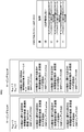
例えば、以下のDCIフォーマットが定義されてよい。
・DCIフォーマット0_0
・DCIフォーマット0_1
・DCIフォーマット1_0
・DCIフォーマット1_1
・DCIフォーマット2_0
・DCIフォーマット2_1
・DCIフォーマット2_2
・DCIフォーマット2_3 For example, the following DCI format may be defined:
-DCI format 0_0
-DCI format 0_1
-DCI format 1_0
-DCI format 1_1
-DCI format 2_0
-DCI format 2_1
・ DCI format 2_2
-DCI format 2_3
・DCIフォーマット0_0
・DCIフォーマット0_1
・DCIフォーマット1_0
・DCIフォーマット1_1
・DCIフォーマット2_0
・DCIフォーマット2_1
・DCIフォーマット2_2
・DCIフォーマット2_3 For example, the following DCI format may be defined:
-DCI format 0_0
-DCI format 0_1
-DCI format 1_0
-DCI format 1_1
-DCI format 2_0
-DCI format 2_1
・ DCI format 2_2
-DCI format 2_3
DCIフォーマット0_0は、PUSCHのスケジューリング情報(周波数領域リソース割当及び時間領域リソース割当)を示す情報を含んでよい。
The DCI format 0_0 may include information indicating PUSCH scheduling information (frequency domain resource allocation and time domain resource allocation).
DCIフォーマット0_1は、PUSCHのスケジューリング情報(周波数領域リソース割当及び時間領域リソース割当)を示す情報、帯域部分(BWP:BandWidth Part)を示す情報、チャネル状態情報(CSI:Channel State Information)リクエスト、サウンディング参照信号(SRS:Sounding Reference Signal)リクエスト、アンテナポートに関する情報を含んでよい。
DCI format 0_1 is information indicating PUSCH scheduling information (frequency domain resource allocation and time domain resource allocation), information indicating band width part (BWP), channel state information (CSI) request, sounding reference A signal (SRS: Sounding Reference Signal) request may include information on an antenna port.
DCIフォーマット1_0は、PDSCHのスケジューリング情報(周波数領域リソース割当及び時間領域リソース割当)を示す情報を含んでよい。
The DCI format 1_0 may include information indicating scheduling information (frequency domain resource assignment and time domain resource assignment) of the PDSCH.
DCIフォーマット1_1は、PDSCHのスケジューリング情報(周波数領域リソース割当及び時間領域リソース割当)を示す情報、帯域部分(BWP)を示す情報、送信設定指示(TCI:Transmission Configuration Indication)、アンテナポートに関する情報を含んでよい。
The DCI format 1_1 includes information indicating scheduling information (frequency domain resource assignment and time domain resource assignment) of PDSCH, information indicating band part (BWP), transmission configuration indication (TCI), and information on antenna port. It is good.
DCIフォーマット2_0は、1つまたは複数のスロットのスロットフォーマットを通知するために用いられる。スロットフォーマットは、スロット内の各OFDMシンボルが下りリンク、フレキシブル、上りリンクのいずれかに分類されたものとして定義される。例えば、スロットフォーマットが28の場合、スロットフォーマット28が指示されたスロット内の14シンボルのOFDMシンボルに対してDDDDDDDDDDDDXUが適用される。ここで、Dが下りリンクシンボル、Xがフレキシブルシンボル、Uが上りリンクシンボルである。なお、スロットについては後述する。
The DCI format 2_0 is used to indicate the slot format of one or more slots. The slot format is defined as that each OFDM symbol in the slot is classified as either downlink, flexible, or uplink. For example, if the slot format is 28, DDDDDDDDDDDDXU is applied to the OFDM symbol of 14 symbols in the slot for which the slot format 28 is designated. Here, D is a downlink symbol, X is a flexible symbol, and U is an uplink symbol. The slots will be described later.
DCIフォーマット2_1は、端末装置1に対して、送信がないと想定してよい物理リソースブロックとOFDMシンボルを通知するために用いられる。なお、この情報はプリエンプション指示(間欠送信指示)と称してよい。
The DCI format 2_1 is used to notify the terminal device 1 of physical resource blocks and OFDM symbols that may be assumed to be absent. This information may be referred to as a preemption instruction (intermittent transmission instruction).
DCIフォーマット2_2は、PUSCHおよびPUSCHのための送信電力制御(TPC:Transmit Power Control)コマンドの送信のために用いられる。
The DCI format 2_2 is used for transmission of a PUSCH and a Transmit Power Control (TPC) command for the PUSCH.
DCIフォーマット2_3は、1または複数の端末装置1によるサウンディング参照信号(SRS)送信のためのTPCコマンドのグループを送信するために用いられる。また、TPCコマンドとともに、SRSリクエストが送信されてもよい。また、DCIフォーマット2_3に、PUSCHおよびPUCCHのない上りリンク、またはSRSの送信電力制御がPUSCHの送信電力制御と紐付いていない上りリンクのために、SRSリクエストとTPCコマンドが定義されてよい。
The DCI format 2_3 is used to transmit a group of TPC commands for sounding reference signal (SRS) transmission by one or more terminal devices 1. Also, an SRS request may be transmitted along with the TPC command. Also, in DCI format 2_3, SRS request and TPC command may be defined for uplink without PUSCH and PUCCH, or uplink for which transmission power control of SRS is not linked with transmission power control of PUSCH.
下りリンクに対するDCIを、下りリンクグラント(downlink grant)、または、下りリンクアサインメント(downlink assignment)とも称する。ここで、上りリンクに対するDCIを、上りリンクグラント(uplink grant)、または、上りリンクアサインメント(Uplink assignment)とも称する。
The DCI for downlink is also referred to as downlink grant or downlink assignment. Here, DCI for uplink is also referred to as uplink grant or uplink assignment.
PUCCHは、上りリンクの無線通信(端末装置1から基地局装置3の無線通信)において、上りリンク制御情報(Uplink Control Information: UCI)を送信するために用いられる。ここで、上りリンク制御情報には、下りリンクのチャネルの状態を示すために用いられるチャネル状態情報(CSI: Channel State Information)が含まれてもよい。また、上りリンク制御情報には、UL-SCHリソースを要求するために用いられるスケジューリング要求(SR: Scheduling Request)が含まれてもよい。また、上りリンク制御情報には、HARQ-ACK(Hybrid Automatic Repeat request ACKnowledgement)が含まれてもよい。HARQ-ACKは、下りリンクデータ(Transport block, Medium Access Control Protocol Data Unit: MAC PDU, Downlink-Shared Channel: DL-SCH)に対するHARQ-ACKを示してもよい。
The PUCCH is used to transmit uplink control information (Uplink Control Information: UCI) in uplink radio communication (radio communication from the terminal device 1 to the base station device 3). Here, the uplink control information may include channel state information (CSI: Channel State Information) used to indicate the state of the downlink channel. Also, the uplink control information may include a scheduling request (SR: Scheduling Request) used to request a UL-SCH resource. Also, the uplink control information may include hybrid automatic repeat request acknowledgment (HARQ-ACK). The HARQ-ACK may indicate a HARQ-ACK for downlink data (Transport block, Medium Access Control Protocol Data Unit: MAC PDU, Downlink-Shared Channel: DL-SCH).
PDSCHは、媒介アクセス(MAC: Medium Access Control)層からの下りリンクデータ(DL-SCH: Downlink Shared CHannel)の送信に用いられる。また、下りリンクの場合にはシステム情報(SI: System Information)やランダムアクセス応答(RAR: Random Access Response)などの送信にも用いられる。
The PDSCH is used to transmit downlink data (DL-SCH: Downlink Shared CHannel) from the Media Access (MAC) layer. Moreover, in the case of downlink, it is also used for transmission of system information (SI: System Information), random access response (RAR: Random Access Response), and the like.
PUSCHは、MAC層からの上りリンクデータ(UL-SCH: Uplink Shared CHannel)または上りリンクデータと共にHARQ-ACKおよび/またはCSIを送信するために用いられてもよい。また、CSIのみ、または、HARQ-ACKおよびCSIのみを送信するために用いられてもよい。すなわち、UCIのみを送信するために用いられてもよい。
The PUSCH may be used to transmit HARQ-ACK and / or CSI together with uplink data (UL-SCH: Uplink Shared CHannel) or uplink data from the MAC layer. Also, it may be used to transmit only CSI or only HARQ-ACK and CSI. That is, it may be used to transmit only UCI.
ここで、基地局装置3と端末装置1は、上位層(higher layer)において信号をやり取り(送受信)する。例えば、基地局装置3と端末装置1は、無線リソース制御(RRC: Radio Resource Control)層において、RRCシグナリング(RRC message: Radio Resource Control message、RRC information: Radio Resource Control informationとも称される)を送受信してもよい。また、基地局装置3と端末装置1は、MAC(Medium Access Control)層において、MACコントロールエレメントを送受信してもよい。ここで、RRCシグナリング、および/または、MACコントロールエレメントを、上位層の信号(higher layer signaling)とも称する。ここでの上位層は、物理層から見た上位層を意味するため、MAC層、RRC層、RLC層、PDCP層、NAS(Non Access Stratum)層などの一つまたは複数を含んでもよい。例えば、MAC層の処理において上位層とは、RRC層、RLC層、PDCP層、NAS層などの一つまたは複数を含んでもよい。
Here, the base station apparatus 3 and the terminal apparatus 1 exchange (transmit and receive) signals in a higher layer. For example, the base station device 3 and the terminal device 1 transmit and receive RRC signaling (RRC message: Radio Resource Control message, also referred to as RRC information: Radio Resource Control information) in a Radio Resource Control (RRC) layer. You may Also, the base station device 3 and the terminal device 1 may transmit and receive MAC control elements in the MAC (Medium Access Control) layer. Here, RRC signaling and / or MAC control elements are also referred to as higher layer signaling. The upper layer here may include one or more of a MAC layer, an RRC layer, an RLC layer, a PDCP layer, a NAS (Non Access Stratum) layer, and the like to mean an upper layer viewed from the physical layer. For example, in the processing of the MAC layer, the upper layer may include one or more of an RRC layer, an RLC layer, a PDCP layer, an NAS layer, and the like.
PDSCHまたはPUSCHは、RRCシグナリング、および、MACコントロールエレメントを送信するために用いられてもよい。ここで、PDSCHにおいて、基地局装置3から送信されるRRCシグナリングは、セル内における複数の端末装置1に対して共通のシグナリングであってもよい。また、基地局装置3から送信されるRRCシグナリングは、ある端末装置1に対して専用のシグナリング(dedicated signalingとも称する)であってもよい。すなわち、端末装置固有(UEスペシフィック)の情報は、ある端末装置1に対して専用のシグナリングを用いて送信されてもよい。また、PUSCHは、上りリンクにおいてUEの能力(UE Capability)の送信に用いられてもよい。
The PDSCH or PUSCH may be used to transmit RRC signaling and MAC control elements. Here, in the PDSCH, RRC signaling transmitted from the base station device 3 may be signaling common to a plurality of terminal devices 1 in a cell. Also, RRC signaling transmitted from the base station device 3 may be dedicated signaling (also referred to as dedicated signaling) for a certain terminal device 1. That is, terminal device specific (UE specific) information may be transmitted to a certain terminal device 1 using dedicated signaling. Moreover, PUSCH may be used for transmission of UE capability (UE Capability) in uplink.
図1において、下りリンクの無線通信では、以下の下りリンク物理信号が用いられる。ここで、下りリンク物理信号は、上位層から出力された情報を送信するために使用されないが、物理層によって使用される。
・同期信号(Synchronization signal: SS)
・参照信号(Reference Signal: RS) In FIG. 1, in downlink radio communication, the following downlink physical signals are used. Here, the downlink physical signal is not used to transmit information output from the upper layer, but is used by the physical layer.
・ Synchronization signal (SS)
・ Reference signal (Reference Signal: RS)
同期信号は、プライマリ同期信号(PSS:Primary Synchronization Signal)およびセカンダリ同期信号(SSS)を含んでよい。PSSとSSSを用いてセルIDが検出されてよい。
The synchronization signal may include a primary synchronization signal (PSS: Primary Synchronization Signal) and a secondary synchronization signal (SSS). The cell ID may be detected using PSS and SSS.
同期信号は、端末装置1が下りリンクの周波数領域および時間領域の同期をとるために用いられる。ここで、同期信号は、端末装置1が基地局装置3によるプリコーディングまたはビームフォーミングにおけるプリコーディングまたはビームの選択に用いられて良い。なお、ビームは、送信または受信フィルタ設定と呼ばれてもよい。
The synchronization signal is used by the terminal device 1 to synchronize the downlink frequency domain and time domain. Here, the synchronization signal may be used by the terminal device 1 for precoding or beamforming in precoding or beamforming by the base station device 3. The beam may also be referred to as transmit or receive filter settings.
参照信号は、端末装置1が物理チャネルの伝搬路補償を行うために用いられる。ここで、参照信号は、端末装置1が下りリンクのCSIを算出するためにも用いられてよい。また、参照信号は、無線パラメータやサブキャリア間隔などのヌメロロジーやFFTの窓同期などができる程度の細かい同期(Fine synchronization)に用いられて良い。
The reference signal is used by the terminal device 1 to perform propagation channel compensation of the physical channel. Here, the reference signal may be used also for the terminal device 1 to calculate downlink CSI. In addition, the reference signal may be used for fine synchronization to such an extent as possible to perform numerology such as radio parameters and subcarrier intervals or window synchronization of FFT.
本実施形態において、以下の下りリンク参照信号のいずれか1つまたは複数が用いられる。
・DMRS(Demodulation Reference Signal)
・CSI-RS(Channel State Information Reference Signal)
・PTRS(Phase Tracking Reference Signal)
・TRS(Tracking Reference Signal) In the present embodiment, any one or more of the following downlink reference signals are used.
-DMRS (Demodulation Reference Signal)
・ CSI-RS (Channel State Information Reference Signal)
・ PTRS (Phase Tracking Reference Signal)
・ TRS (Tracking Reference Signal)
DMRSは、変調信号を復調するために使用される。なお、DMRSには、PBCHを復調するための参照信号と、PDSCHを復調するための参照信号の2種類が定義されてもよいし、両方をDMRSと称してもよい。CSI-RSは、チャネル状態情報(CSI:Channel State Information)の測定およびビームマネジメントに使用される。PTRSは、位相雑音に起因する周波数オフセットを保証する目的で、時間軸で位相をトラックするために使用される。TRSは、高速移動時におけるドップラーシフトを保証するために使用される。なお、TRSはCSI-RSの1つの設定として用いられてよい。例えば、1ポートのCSI-RSがTRSとして無線リソースが設定されてもよい。
DMRS is used to demodulate the modulated signal. Note that, in DMRS, two types of a reference signal for demodulating PBCH and a reference signal for demodulating PDSCH may be defined, or both may be referred to as DMRS. CSI-RS is used for channel state information (CSI: Channel State Information) measurement and beam management. The PTRS is used to track phase in the time axis in order to guarantee frequency offset due to phase noise. The TRS is used to guarantee the Doppler shift at high speed movement. In addition, TRS may be used as one setting of CSI-RS. For example, a radio resource may be set as a one-port CSI-RS as a TRS.
本実施形態において、以下の上りリンク参照信号のいずれか1つまたは複数が用いられる。
・DMRS(Demodulation Reference Signal)
・PTRS(Phase Tracking Reference Signal)
・SRS(Sounding Reference Signal) In the present embodiment, any one or more of the following uplink reference signals are used.
-DMRS (Demodulation Reference Signal)
・ PTRS (Phase Tracking Reference Signal)
・ SRS (Sounding Reference Signal)
DMRSは、変調信号を復調するために使用される。なお、DMRSには、PUCCHを復調するための参照信号と、PUSCHを復調するための参照信号の2種類が定義されてもよいし、両方をDMRSと称してもよい。SRSは、上りリンクチャネル状態情報(CSI)の測定、チャネルサウンディング、およびビームマネジメントに使用される。PTRSは、位相雑音に起因する周波数オフセットを保証する目的で、時間軸で位相をトラックするために使用される。
DMRS is used to demodulate the modulated signal. In DMRS, two types of a reference signal for demodulating PUCCH and a reference signal for demodulating PUSCH may be defined, or both may be referred to as DMRS. SRS is used for uplink channel state information (CSI) measurement, channel sounding, and beam management. The PTRS is used to track phase in the time axis in order to guarantee frequency offset due to phase noise.
下りリンク物理チャネルおよび/または下りリンク物理シグナルを総称して、下りリンク信号と称する。上りリンク物理チャネルおよび/または上りリンク物理シグナルを総称して、上りリンク信号と称する。下りリンク物理チャネルおよび/または上りリンク物理チャネルを総称して、物理チャネルと称する。下りリンク物理シグナルおよび/または上りリンク物理シグナルを総称して、物理シグナルと称する。
The downlink physical channel and / or the downlink physical signal are collectively referred to as a downlink signal. Uplink physical channels and / or uplink physical signals are collectively referred to as uplink signals. The downlink physical channel and / or the uplink physical channel are collectively referred to as a physical channel. Downlink physical signals and / or uplink physical signals are collectively referred to as physical signals.
BCH、UL-SCHおよびDL-SCHは、トランスポートチャネルである。媒体アクセス制御(MAC:Medium Access Control)層で用いられるチャネルをトランスポートチャネルと称する。MAC層で用いられるトランスポートチャネルの単位を、トランスポートブロック(TB:transport block)および/またはMAC PDU(Protocol Data Unit)とも称する。MAC層においてトランスポートブロック毎にHARQ(Hybrid Automatic Repeat reQuest)の制御が行われる。トランスポートブロックは、MAC層が物理層に渡す(deliver)データの単位である。物理層において、トランスポートブロックはコードワードにマップされ、コードワード毎に符号化処理が行われる。
BCH, UL-SCH and DL-SCH are transport channels. A channel used in a medium access control (MAC) layer is called a transport channel. The unit of transport channel used in the MAC layer is also referred to as transport block (TB) and / or MAC PDU (Protocol Data Unit). In the MAC layer, control of HARQ (Hybrid Automatic Repeat request) is performed for each transport block. The transport block is a unit of data delivered by the MAC layer to the physical layer. In the physical layer, transport blocks are mapped to codewords, and encoding processing is performed for each codeword.
また、参照信号は、無線リソース測定(RRM:Radio Resource Measurement)に用いられてよい。また、参照信号は、ビームマネジメントに用いられてよい。
Also, the reference signal may be used for Radio Resource Measurement (RRM). Also, the reference signal may be used for beam management.
ビームマネジメントは、送信装置(下りリンクの場合は基地局装置3であり、上りリンクの場合は端末装置1である)におけるアナログおよび/またはディジタルビームと、受信装置(下りリンクの場合は端末装置1、上りリンクの場合は基地局装置3である)におけるアナログおよび/またはディジタルビームの指向性を合わせ、ビーム利得を獲得するための基地局装置3および/または端末装置1の手続きであってよい。
Beam management includes an analog and / or digital beam in a transmitter (the base station 3 in the case of downlink and the terminal 1 in the case of uplink) and a receiver (the terminal 1 in the case of downlink) In the case of uplink, it is the procedure of the base station apparatus 3 and / or the terminal apparatus 1 for aligning the directivity of analog and / or digital beams in the base station apparatus 3) and acquiring beam gain.
なお、ビームペアリンクを構成、設定または確立する手続きとして、下記の手続きを含んでよい。
・ビーム選択(Beam selection)
・ビーム改善(Beam refinement)
・ビームリカバリ(Beam recovery) The following procedure may be included as a procedure for configuring, setting or establishing a beam pair link.
・ Beam selection (Beam selection)
・ Beam improvement (Beam refinement)
・ Beam recovery
・ビーム選択(Beam selection)
・ビーム改善(Beam refinement)
・ビームリカバリ(Beam recovery) The following procedure may be included as a procedure for configuring, setting or establishing a beam pair link.
・ Beam selection (Beam selection)
・ Beam improvement (Beam refinement)
・ Beam recovery
例えば、ビーム選択は、基地局装置3と端末装置1の間の通信においてビームを選択する手続きであってよい。また、ビーム改善は、さらに利得の高いビームの選択、あるいは端末装置1の移動によって最適な基地局装置3と端末装置1の間のビームの変更をする手続きであってよい。ビームリカバリは、基地局装置3と端末装置1の間の通信において遮蔽物や人の通過などにより生じるブロッケージにより通信リンクの品質が低下した際にビームを再選択する手続きであってよい。
For example, beam selection may be a procedure for selecting a beam in communication between the base station device 3 and the terminal device 1. Further, the beam improvement may be a procedure of selecting a beam with a further higher gain or changing the beam between the optimal base station device 3 and the terminal device 1 by the movement of the terminal device 1. The beam recovery may be a procedure for reselecting the beam when the quality of the communication link is degraded due to a blockage caused by the passage of a shield or a person in the communication between the base station device 3 and the terminal device 1.
ビームマネジメントには、ビーム選択、ビーム改善が含まれてよい。ビームリカバリには、下記の手続きを含んでよい。
・ビーム失敗(beam failure)の検出
・新しいビームの発見
・ビームリカバリリクエストの送信
・ビームリカバリリクエストに対する応答のモニタ Beam management may include beam selection, beam improvement. The beam recovery may include the following procedures.
-Detection of beam failure-Discovery of a new beam-Transmission of beam recovery request-Monitoring of response to beam recovery request
例えば、端末装置1における基地局装置3の送信ビームを選択する際にCSI-RSまたはSS/PBCHブロックに含まれるSSSのRSRP(Reference Signal Received Power)を用いてもよいし、CSIを用いてもよい。また、基地局装置3への報告としてCSI-RSリソースインデックス(CRI:CSI-RS Resource Index)を用いてもよいし、SS/PBCHブロックに含まれるPBCHおよび/またはPBCHの復調に用いられる復調用参照信号(DMRS)の系列で指示されるインデックスを用いてもよい。
For example, when selecting the transmission beam of the base station apparatus 3 in the terminal device 1, RSRP (Reference Signal Received Power) of SSS included in CSI-RS or SS / PBCH block may be used, or CSI may be used. Good. Also, a CSI-RS resource index (CRI: CSI-RS Resource Index) may be used as a report to the base station apparatus 3, or it may be used for demodulation of PBCH and / or PBCH included in the SS / PBCH block. An index indicated by a sequence of reference signals (DMRS) may be used.
また、基地局装置3は、端末装置1へビームを指示する際にCRIまたはSS/PBCHの時間インデックスを指示し、端末装置1は、指示されたCRIまたはSS/PBCHの時間インデックスに基づいて受信する。このとき、端末装置1は指示されたCRIまたはSS/PBCHの時間インデックスに基づいて空間フィルタを設定し、受信してよい。また、端末装置1は、疑似同位置(QCL:Quasi-Co-Location)の想定を用いて受信してもよい。ある信号(アンテナポート、同期信号、参照信号など)が別の信号(アンテナポート、同期信号、参照信号など)とQCLであるまたは、QCL想定されるとは、ある信号が別の信号と関連付けられていると解釈できる。
Also, the base station apparatus 3 instructs the time index of CRI or SS / PBCH when instructing the terminal apparatus 1 to perform a beam, and the terminal apparatus 1 receives based on the instructed time index of CRI or SS / PBCH Do. At this time, the terminal device 1 may set and receive a spatial filter based on the indicated CRI or SS / PBCH time index. Moreover, the terminal device 1 may receive using the assumption of quasi co-location (QCL: Quasi-Co-Location). If one signal (antenna port, synchronization signal, reference signal, etc.) is another signal (antenna port, synchronization signal, reference signal, etc.) and QCL or QCL is assumed, then one signal is associated with another signal. It can be interpreted as
もしあるアンテナポートにおけるあるシンボルが搬送されるチャネルの長区間特性(Long Term Property)が他方のアンテナポートにおけるあるシンボルが搬送されるチャネルから推論されうるなら、2つのアンテナポートはQCLであるといわれる。チャネルの長区間特性は、遅延スプレッド、ドップラースプレッド、ドップラーシフト、平均利得、及び平均遅延の1つまたは複数を含む。例えば、アンテナポート1とアンテナポート2が平均遅延に関してQCLである場合、アンテナポート1の受信タイミングからアンテナポート2の受信タイミングが推論されうることを意味する。
Two antenna ports are said to be QCL, if the Long Term Property of the channel on which one symbol at one antenna port is carried can be deduced from the channel at which one symbol on the other antenna port is carried . The long span characteristics of the channel include one or more of delay spread, Doppler spread, Doppler shift, average gain, and average delay. For example, if antenna port 1 and antenna port 2 are QCL with respect to average delay, it means that the reception timing of antenna port 2 can be deduced from the reception timing of antenna port 1.
このQCLは、ビームマネジメントにも拡張されうる。そのために、空間に拡張したQCLが新たに定義されてもよい。例えば、空間のQCL想定におけるチャネルの長区間特性(Long term property)として、無線リンクあるいはチャネルにおける到来角(AoA(Angle of Arrival), ZoA(Zenith angle of Arrival)など)および/または角度広がり(Angle Spread、例えばASA(Angle Spread of Arrival)やZSA(Zenith angle Spread of Arrival))、送出角(AoD, ZoDなど)やその角度広がり(Angle Spread、例えばASD(Angle Spread of Departure)やZSD(Zenith angle Spread of Departure))、空間相関(Spatial Correlation)、受信空間パラメータであってもよい。
This QCL can be extended to beam management. For this purpose, a QCL expanded in space may be newly defined. For example, as a long term property of a channel in the QCL assumption of space, an arrival angle (AoA (Angle of Arrival), ZoA (Zenith angle of Arrival), etc.) and / or an angle spread (AoA). Spread, eg ASA (Angle Spread of Arrival) or ZSA (Zenith angle Spread of Arrival), transmission angle (AoD, ZoD etc.) or its angular spread (Angle Spread, eg ASD (Angle Spread of Departure) or ZSD (Zenith angle) Spread of Departure)), spatial correlation (Spatial Correlation) may be received spatial parameters.
例えば、アンテナポート1とアンテナポート2の間で受信空間パラメータに関してQCLであるとみなせる場合、アンテナポート1からの信号を受信する受信ビーム(受信空間フィルタ)からアンテナポート2からの信号を受信する受信ビームが推論されうることを意味する。
For example, if it can be considered as a QCL in terms of receive spatial parameters between antenna port 1 and antenna port 2, receive signal from antenna port 2 from the receive beam (receive spatial filter) that receives signal from antenna port 1 It means that the beam can be inferred.
QCLタイプとして、QCLとみなしてよい長区間特性の組み合わせが定義されてよい。例えば、以下のタイプが定義されてよい。
・タイプA:ドップラーシフト、ドップラースプレッド、平均遅延、遅延スプレッド
・タイプB:ドップラーシフト、ドップラースプレッド
・タイプC:平均遅延、ドップラーシフト
・タイプD:受信空間パラメータ As the QCL type, a combination of long interval characteristics that may be regarded as the QCL may be defined. For example, the following types may be defined:
Type A: Doppler shift, Doppler spread, average delay, delay spread Type B: Doppler shift, Doppler spread Type C: average delay, Doppler shift Type D: receive spatial parameter
上述のQCLタイプは、RRCおよび/またはMAC層および/またはDCIで1つまたは2つの参照信号とPDCCHやPDSCH DMRSとのQCL想定を送信設定指示(TCI:Transmission Configuration Indication)として設定および/または指示してもよい。例えば、端末装置1がPDCCHを受信する際のTCIの1つの状態として、PBCH/SSブロックのインデックス#2とQCLタイプA+QCLタイプBが設定および/または指示された場合、端末装置1は、PDCCH DMRSを受信する際、PBCH/SSブロックインデックス#2の受信におけるドップラーシフト、ドップラースプレッド、平均遅延、遅延スプレッド、受信空間パラメータとチャネルの長区間特性とみなしてPDCCHのDMRSを受信して同期や伝搬路推定をしてもよい。このとき、TCIにより指示される参照信号(上述の例ではPBCH/SSブロック)をソース参照信号、ソース参照信号を受信する際のチャネルの長区間特性から推論される長区間特性の影響を受ける参照信号(上述の例ではPDCCH DMRS)をターゲット参照信号と称してよい。また、TCIは、RRCで複数のTCI状態と各状態に対してソース参照信号とQCLタイプの組み合わせが設定され、MAC層またはDCIにより端末装置1に指示されてよい。
The above QCL type sets and / or indicates the QCL assumption of one or two reference signals and PDCCH or PDSCH DMRS in the RRC and / or MAC layer and / or DCI as a transmission configuration indication (TCI). You may For example, when the index # 2 of the PBCH / SS block and QCL type A + QCL type B are set and / or indicated as one state of TCI when the terminal device 1 receives the PDCCH, the terminal device 1 performs PDCCH DMRS When receiving the PBCH / SS block index # 2, receive Doppler shift, Doppler spread, average delay, delay spread, receive spatial parameter and channel long-term characteristic and receive DMRS of PDCCH to synchronize or propagate It may be estimated. At this time, the reference signal indicated by TCI (the PBCH / SS block in the above example) is a source reference signal, and the reference is influenced by the long interval characteristic inferred from the long interval characteristic of the channel when receiving the source reference signal. The signal (in the above example, PDCCH DMRS) may be referred to as a target reference signal. Further, in TCI, combinations of source reference signals and QCL types may be set for a plurality of TCI states and respective states in RRC, and may be indicated to the terminal device 1 by the MAC layer or DCI.
この方法により、ビームマネジメントおよびビーム指示/報告として、空間のQCL想定と無線リソース(時間および/または周波数)によりビームマネジメントと等価な基地局装置3、端末装置1の動作が定義されてもよい。
By this method, the operation of the base station apparatus 3 and the terminal apparatus 1 equivalent to beam management may be defined as the beam management and beam indication / report by the QCL assumption of space and radio resources (time and / or frequency).
以下、サブフレームについて説明する。本実施形態ではサブフレームと称するが、リソースユニット、無線フレーム、時間区間、時間間隔などと称されてもよい。
Hereinafter, subframes will be described. Although referred to as a subframe in this embodiment, it may be referred to as a resource unit, a radio frame, a time interval, a time interval, and the like.
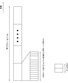
図2は、本発明の第1の実施形態に係る下りリンクスロットの概略構成の一例を示す図である。無線フレームのそれぞれは、10ms長である。また、無線フレームのそれぞれは10個のサブフレームおよびW個のスロットから構成される。また、1スロットは、X個のOFDMシンボルで構成される。つまり、1サブフレームの長さは1msである。スロットのそれぞれは、サブキャリア間隔によって時間長が定義される。例えば、OFDMシンボルのサブキャリア間隔が15kHz、NCP(Normal Cyclic Prefix)の場合、X=7あるいはX=14であり、それぞれ0.5msおよび1msである。また、サブキャリア間隔が60kHzの場合は、X=7あるいはX=14であり、それぞれ0.125msおよび0.25msである。また、例えば、X=14の場合、サブキャリア間隔が15kHzの場合はW=10であり、サブキャリア間隔が60kHzの場合はW=40である。図2は、X=7の場合を一例として示している。なお、X=14の場合にも同様に拡張できる。また、上りリンクスロットも同様に定義され、下りリンクスロットと上りリンクスロットは別々に定義されてもよい。また、図2のセルの帯域幅は帯域の一部(BWP:BandWidth Part)として定義されてもよい。また、スロットは、送信時間間隔(TTI:Transmission Time Interval)と定義されてもよい。スロットは、TTIとして定義されなくてもよい。TTIは、トランスポートブロックの送信期間であってもよい。
FIG. 2 is a diagram showing an example of a schematic configuration of a downlink slot according to the first embodiment of the present invention. Each radio frame is 10 ms long. Also, each radio frame is composed of 10 subframes and W slots. Also, one slot is composed of X OFDM symbols. That is, the length of one subframe is 1 ms. Each slot has a time length defined by subcarrier spacing. For example, when the subcarrier interval of the OFDM symbol is 15 kHz and NCP (Normal Cyclic Prefix), X = 7 or X = 14, and 0.5 ms and 1 ms, respectively. Further, when the subcarrier spacing is 60 kHz, X = 7 or X = 14, which is 0.125 ms and 0.25 ms, respectively. Also, for example, in the case of X = 14, W = 10 when the subcarrier spacing is 15 kHz, and W = 40 when the subcarrier spacing is 60 kHz. FIG. 2 shows the case of X = 7 as an example. The same can be applied to the case of X = 14. Also, uplink slots may be similarly defined, and downlink slots and uplink slots may be defined separately. Also, the bandwidth of the cell of FIG. 2 may be defined as part of a band (BWP: Band Width Part). Also, a slot may be defined as a transmission time interval (TTI). A slot may not be defined as a TTI. The TTI may be a transport block transmission period.
スロットのそれぞれにおいて送信される信号または物理チャネルは、リソースグリッドによって表現されてよい。リソースグリッドは、複数のサブキャリアと複数のOFDMシンボルによって定義される。1つのスロットを構成するサブキャリアの数は、セルの下りリンクおよび上りリンクの帯域幅にそれぞれ依存する。リソースグリッド内のエレメントのそれぞれをリソースエレメントと称する。リソースエレメントは、サブキャリアの番号とOFDMシンボルの番号とを用いて識別されてよい。
The signal or physical channel transmitted in each of the slots may be represented by a resource grid. A resource grid is defined by multiple subcarriers and multiple OFDM symbols. The number of subcarriers constituting one slot depends on the downlink and uplink bandwidths of the cell, respectively. Each of the elements in the resource grid is called a resource element. Resource elements may be identified using subcarrier numbers and OFDM symbol numbers.
リソースグリッドは、ある物理下りリンクチャネル(PDSCHなど)あるいは上りリンクチャネル(PUSCHなど)のリソースエレメントのマッピングを表現するために用いられる。例えば、サブキャリア間隔が15kHzの場合、サブフレームに含まれるOFDMシンボル数X=14で、NCPの場合には、1つの物理リソースブロックは、時間領域において14個の連続するOFDMシンボルと周波数領域において12*Nmax個の連続するサブキャリアとから定義される。Nmaxは、後述するサブキャリア間隔設定μにより決定されるリソースブロックの最大数である。つまり、リソースグリッドは、(14*12*Nmax,μ)個のリソースエレメントから構成される。ECP(Extended CP)の場合、サブキャリア間隔60kHzにおいてのみサポートされるので、1つの物理リソースブロックは、例えば、時間領域において12(1スロットに含まれるOFDMシンボル数)*4(1サブフレームに含まれるスロット数)=48個の連続するOFDMシンボルと、周波数領域において12*Nmax,μ個の連続するサブキャリアとにより定義される。つまり、リソースグリッドは、(48*12*Nmax,μ)個のリソースエレメントから構成される。
The resource grid is used to represent the mapping of resource elements of a certain physical downlink channel (such as PDSCH) or uplink channel (such as PUSCH). For example, if the subcarrier spacing is 15 kHz, the number of OFDM symbols X included in a subframe is X = 14, and if NCP, one physical resource block is in the frequency domain with 14 consecutive OFDM symbols in the time domain. It is defined from 12 * Nmax consecutive subcarriers. Nmax is the maximum number of resource blocks determined by subcarrier spacing setting μ described later. That is, the resource grid is composed of (14 * 12 * Nmax, μ) resource elements. In the case of ECP (Extended CP), one physical resource block is, for example, 12 (number of OFDM symbols included in one slot) * 4 (included in one subframe) in the time domain because it is supported only at subcarrier spacing 60 kHz. The number of slots) = 48 consecutive OFDM symbols and 12 * Nmax in the frequency domain, defined by μ consecutive subcarriers. That is, the resource grid is composed of (48 * 12 * Nmax, μ) resource elements.
リソースブロックとして、参照リソースブロック、共通リソースブロック、物理リソースブロック、仮想リソースブロックが定義される。1リソースブロックは、周波数領域で連続する12サブキャリアとして定義される。参照リソースブロックは、全てのサブキャリアにおいて共通であり、例えば15kHzのサブキャリア間隔でリソースブロックを構成し、昇順に番号が付されてよい。参照リソースブロックインデックス0におけるサブキャリアインデックス0は、参照ポイントAと称されてよい(単に“参照ポイント”と称されてもよい)。共通リソースブロックは、参照ポイントAから各サブキャリア間隔設定μにおいて0から昇順で番号が付されるリソースブロックである。上述のリソースグリッドはこの共通リソースブロックにより定義される。物理リソースブロックは、後述する帯域部分(BWP)の中に含まれる0から昇順で番号が付されたリソースブロックであり、物理リソースブロックは、帯域部分(BWP)の中に含まれる0から昇順で番号が付されたリソースブロックである。ある物理上りリンクチャネルは、まず仮想リソースブロックにマップされる。その後、仮想リソースブロックは、物理リソースブロックにマップされる。(TS38.211より)
Reference resource blocks, common resource blocks, physical resource blocks, and virtual resource blocks are defined as resource blocks. One resource block is defined as 12 consecutive subcarriers in the frequency domain. The reference resource blocks are common to all subcarriers, and may be resource blocks in subcarrier intervals of, for example, 15 kHz, and may be numbered in ascending order. Subcarrier index 0 at reference resource block index 0 may be referred to as reference point A (may be referred to simply as "reference point"). The common resource block is a resource block numbered from 0 in ascending order from reference point A to each subcarrier spacing setting μ. The above resource grid is defined by this common resource block. Physical resource blocks are resource blocks numbered in ascending order from 0 contained in a band part (BWP) described later, and physical resource blocks are arranged in ascending order from 0 contained in a band part (BWP) It is a resource block numbered. Certain physical uplink channels are first mapped to virtual resource blocks. The virtual resource blocks are then mapped to physical resource blocks. (From TS 38.211)
次に、サブキャリア間隔設定μについて説明する。上述のようにNRでは、複数のOFDMヌメロロジーがサポートされる。あるBWPにおいて、サブキャリア間隔設定μ(μ=0,1,...,5)と、サイクリックプレフィックス長は、下りリンクのBWPに対して上位レイヤ(上位層)で与えられ、上りリンクのBWPにおいて上位レイヤで与えられる。ここで、μが与えられると、サブキャリア間隔Δfは、Δf=2^μ・15(kHz)で与えられる。
Next, subcarrier spacing setting μ will be described. As mentioned above, NR supports multiple OFDM numerologies. In a certain BWP, subcarrier spacing setting μ (μ = 0, 1, ..., 5) and cyclic prefix length are given to the downlink BWP in the upper layer (upper layer), and uplink It is given in the upper layer in BWP. Here, given μ, the subcarrier spacing Δf is given by Δf = 2 ^ μ · 15 (kHz).
サブキャリア間隔設定μにおいて、スロットは、サブフレーム内で0からN^{subframe,μ}_{slot}-1に昇順に数えられ、フレーム内で0からN^{frame,μ}_{slot}-1に昇順に数えられる。スロット設定およびサイクリックプレフィックスに基づいてN^{slot}_{symb}の連続するOFDMシンボルがスロット内にある。N^{slot}_{symb}は14である。サブフレーム内のスロットn^{μ}_{s}のスタートは、同じサブフレーム内のn^{μ}_{s} N^{slot}_{symb}番目のOFDMシンボルのスタートと時間でアラインされている。
In subcarrier spacing setting μ, slots are counted in ascending order from 0 to N ^ {subframe, μ} _ {slot} -1 in a subframe, and from 0 to N ^ {frame, μ} _ {slot in a frame. It is counted in ascending order of} -1. There are N ^ {slot} _ {symb} consecutive OFDM symbols in the slot based on slot configuration and cyclic prefix. N ^ {slot} _ {symb} is 14. The start of slot n ^ {μ} _ {s} in a subframe corresponds to the start and time of the n ^ {μ} _ {s} N ^ {slot} _ {symb} th OFDM symbol in the same subframe. It is aligned.
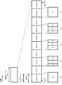
次に、サブフレーム、スロット、ミニスロットについて説明する。図3は、サブフレーム、スロット、ミニスロットの時間領域における関係を示した図である。同図のように、3種類の時間ユニットが定義される。サブフレームは、サブキャリア間隔によらず1msであり、スロットに含まれるOFDMシンボル数は7または14であり、スロット長はサブキャリア間隔により異なる。ここで、サブキャリア間隔が15kHzの場合、1サブフレームには14OFDMシンボル含まれる。下りリンクスロットはPDSCHマッピングタイプAと称されてよい。上りリンクスロットはPUSCHマッピングタイプAと称されてよい。
Next, subframes, slots and minislots will be described. FIG. 3 is a diagram showing the relationship between subframes, slots, and minislots in the time domain. As shown, three types of time units are defined. A subframe is 1 ms regardless of subcarrier spacing, the number of OFDM symbols included in the slot is 7 or 14, and the slot length varies depending on the subcarrier spacing. Here, when the subcarrier spacing is 15 kHz, one OFDM contains 14 OFDM symbols. The downlink slot may be referred to as PDSCH mapping type A. The uplink slot may be referred to as PUSCH mapping type A.
ミニスロット(サブスロットと称されてもよい)は、スロットに含まれるOFDMシンボル数よりも少ないOFDMシンボルで構成される時間ユニットである。同図はミニスロットが2OFDMシンボルで構成される場合を一例として示している。ミニスロット内のOFDMシンボルは、スロットを構成するOFDMシンボルタイミングに一致してもよい。なお、スケジューリングの最小単位はスロットまたはミニスロットでよい。また、ミニスロットを割り当てることを、ノンスロットベースのスケジューリングと称してもよい。また、ミニスロットをスケジューリングされることを参照信号とデータのスタート位置の相対的な時間位置が固定であるリソースがスケジュールされたと表現されてもよい。下りリンクミニスロットはPDSCHマッピングタイプBと称されてよい。上りリンクミニスロットはPUSCHマッピングタイプBと称されてよい。
A minislot (which may also be referred to as a subslot) is a time unit comprised of fewer OFDM symbols than the number of OFDM symbols contained in the slot. The figure shows, as an example, the case where the minislot is composed of two OFDM symbols. The OFDM symbols in the minislot may coincide with the OFDM symbol timing that comprises the slot. The minimum unit of scheduling may be slots or minislots. Also, allocating minislots may be referred to as non-slot based scheduling. Also, it may be described that resources in which relative time positions of reference signals and start positions of data are fixed are scheduled to be scheduled minislots. The downlink minislot may be referred to as PDSCH mapping type B. The uplink minislot may be referred to as PUSCH mapping type B.
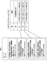
図4は、スロットフォーマットの一例を示す図である。ここでは、サブキャリア間隔15kHzにおいてスロット長が1msの場合を例として示している。同図において、Dは下りリンク、Uは上りリンクを示している。同図に示されるように、ある時間区間内(例えば、システムにおいて1つのUEに対して割り当てなければならない最小の時間区間)においては、
・下りリンクシンボル
・フレキシブルシンボル
・上りリンクシンボル
のうち1つまたは複数を含んでよい。なお、これらの割合はスロットフォーマットとして予め定められてもよい。また、スロット内に含まれる下りリンクのOFDMシンボル数またはスロット内のスタート位置および終了位置で定義されてもよい。また、スロット内に含まれる上りリンクのOFDMシンボルまたはDFT-S-OFDMシンボル数またはスロット内のスタート位置および終了位置で定義されてよい。なお、スロットをスケジューリングされることを参照信号とスロット境界の相対的な時間位置が固定であるリソースがスケジュールされたと表現されてもよい。 FIG. 4 is a diagram showing an example of the slot format. Here, the case where the slot length is 1 ms at a subcarrier spacing of 15 kHz is shown as an example. In the figure, D indicates downlink and U indicates uplink. As shown in the figure, within a certain time interval (for example, the minimum time interval that must be allocated to one UE in the system),
It may include one or more of downlink symbols, flexible symbols, and uplink symbols. Note that these ratios may be predetermined as slot formats. Also, it may be defined by the number of downlink OFDM symbols included in the slot or the start position and end position in the slot. Also, it may be defined by the number of uplink OFDM symbols or DFT-S-OFDM symbols included in the slot or the start position and end position in the slot. It should be noted that scheduling a slot may be described as a resource in which the relative time position of the reference signal and the slot boundary is fixed is scheduled.
端末装置1は、下りリンクシンボルまたはフレキシブルシンボルで下りリンク信号または下りリンクチャネルを受信してよい。端末装置1は、上りリンクシンボルまたはフレキシブルシンボルで上りリンク信号または下りリンクチャネルを送信してよい。
The terminal device 1 may receive a downlink signal or downlink channel in downlink symbols or flexible symbols. The terminal device 1 may transmit the uplink signal or the downlink channel in the uplink symbol or the flexible symbol.
図4(a)は、ある時間区間(例えば、1UEに割当可能な時間リソースの最小単位、またはタイムユニットなどとも称されてよい。また、時間リソースの最小単位を複数束ねてタイムユニットと称されてもよい。)で、全て下りリンク送信に用いられている例であり、図4(b)は、最初の時間リソースで例えばPDCCHを介して上りリンクのスケジューリングを行い、PDCCHの処理遅延及び下りから上りの切り替え時間、送信信号の生成を含むフレキシブルシンボルを介して上りリンク信号を送信する。図4(c)は、最初の時間リソースでPDCCHおよび/または下りリンクのPDSCHの送信に用いられ、処理遅延及び下りから上りの切り替え時間、送信信号の生成のためのギャップを介してPUSCHまたはPUCCHの送信に用いられる。ここで、一例としては、上りリンク信号はHARQ-ACKおよび/またはCSI、すなわちUCIの送信に用いられてよい。図4(d)は、最初の時間リソースでPDCCHおよび/またはPDSCHの送信に用いられ、処理遅延及び下りから上りの切り替え時間、送信信号の生成のためのギャップを介して上りリンクのPUSCHおよび/またはPUCCHの送信に用いられる。ここで、一例としては、上りリンク信号は上りリンクデータ、すなわちUL-SCHの送信に用いられてもよい。図4(e)は、全て上りリンク送信(PUSCHまたはPUCCH)に用いられている例である。
4 (a) may also be referred to as a certain time interval (eg, the smallest unit of time resources allocatable to one UE, or a time unit, etc.) Also, a plurality of smallest units of time resources are bundled and referred to as a time unit. In the example shown in FIG. 4 (b), uplink scheduling is performed on the first time resource via, for example, the PDCCH, and the processing delay and downlink of the PDCCH are performed. The uplink signal is transmitted via a flexible symbol including an uplink switching time and generation of a transmission signal. FIG. 4 (c) is used for transmission of PDCCH and / or downlink PDSCH in the first time resource, and processing delay and downlink to uplink switching time, PUSCH or PUCCH through gaps for transmission signal generation. Used to send Here, as an example, the uplink signal may be used for transmission of HARQ-ACK and / or CSI, ie UCI. FIG. 4 (d) is used for transmission of PDCCH and / or PDSCH in the first time resource, processing delay and downlink to uplink switching time, uplink PUSCH and / or uplink via gap for transmission signal generation. Or used for PUCCH transmission. Here, as an example, the uplink signal may be used for transmission of uplink data, that is, UL-SCH. FIG. 4 (e) is an example used for all uplink transmission (PUSCH or PUCCH).
上述の下りリンクパート、上りリンクパートは、LTEと同様複数のOFDMシンボルで構成されてよい。
The above-mentioned downlink part and uplink part may be configured by a plurality of OFDM symbols as in LTE.
図5は、ビームフォーミングの一例を示した図である。複数のアンテナエレメントは1つの送信ユニット(TXRU: Transceiver unit)10に接続され、アンテナエレメント毎の位相シフタ11によって位相を制御し、アンテナエレメント12から送信することで送信信号に対して任意の方向にビームを向けることができる。典型的には、TXRUがアンテナポートとして定義されてよく、端末装置1においてはアンテナポートのみが定義されてよい。位相シフタ11を制御することで任意の方向に指向性を向けることができるため、基地局装置3は端末装置1に対して利得の高いビームを用いて通信することができる。
FIG. 5 is a diagram showing an example of beam forming. A plurality of antenna elements are connected to one transmission unit (TXRU: Transceiver unit) 10, the phase is controlled by the phase shifter 11 for each antenna element, and transmission from the antenna element 12 makes it possible to transmit signals from any direction. You can direct the beam. Typically, TXRU may be defined as an antenna port, and in the terminal device 1, only an antenna port may be defined. Since the directivity can be directed in any direction by controlling the phase shifter 11, the base station device 3 can communicate with the terminal device 1 using a beam with high gain.
以下、帯域部分(BWP)について説明する。BWPは、キャリアBWPとも称される。BWPは、下りリンクと上りリンクのそれぞれに設定されてよい。BWPは、共通リソースブロックの連続するサブセットから選択された連続する物理リソースの集合として定義される。端末装置1は、ある時間に1つの下りリンクキャリアBWPが活性化される4つまでのBWPを設定されうる。端末装置1は、ある時間に1つの上りリンクキャリアBWPが活性化される4つまでのBWPを設定されうる。キャリアアグリゲーションの場合には、BWPは各サービングセルで設定されてもよい。このとき、あるサービングセルにおいてBWPが1つ設定されていることを、BWPが設定されていないと表現されてもよい。また、BWPが2つ以上設定されていることをBWPが設定されていると表現されてもよい。
The band portion (BWP) will be described below. BWP is also referred to as carrier BWP. The BWP may be configured for downlink and uplink, respectively. A BWP is defined as a set of contiguous physical resources selected from contiguous subsets of common resource blocks. The terminal device 1 can set up to four BWPs in which one downlink carrier BWP is activated at a certain time. The terminal device 1 can set up to four BWPs in which one uplink carrier BWP is activated at a certain time. In the case of carrier aggregation, BWP may be configured in each serving cell. At this time, the fact that one BWP is set in a given serving cell may be expressed as no BWP is set. Also, that two or more BWPs are set may be expressed as BWPs are set.
活性化されたサービングセルにおいて、常に一つのアクティブな(活性化された)BWPがある。あるサービングセルに対するBWP切り替え(BWP switching)は、インアクティブな(非活性化された)BWPを活性化(activate)し、アクティブな(活性化された)BWPを非活性化(deactivate)するために使用される。あるサービングセルに対するBWP切り替え(BWP switching)は、下りリンク割り当てまたは上りリンクグラントを示すPDCCHによって制御される。SpCell(PCellまたはPSCell)の追加または、SCellの活性化において、一つのBWPが、下りリンク割り当てまたは上りリンクグラントを示すPDCCHを受信することなしに初期的にアクティブである。初期的にアクティブなBWPは、基地局装置3から端末装置1に送られるRRCメッセージで指定されるかもしれない。あるサービングセルに対するアクティブなBWPは、基地局装置3から端末装置1に送られるRRCまたはPDCCHで指定される。アンペアードスペクトラム(Unpaired spectrum)(TDDバンドなど)では、DL BWPとUL BWPはペアされていて、BWP切り替えは、ULとDLに対して共通である。BWPが設定されているアクティベートされたサービングセルのそれぞれに対する、アクティブなBWPにおいて、端末装置1のMACエンティティは、ノーマル処理を適用する。ノーマル処理には、UL-SCHを送信する、RACHを送信する、PDCCHをモニタする、PUCCHを送信する、およびDL-SCHを受信することを含む。BWPが設定されているアクティベートされたサービングセルのそれぞれに対する、インアクティブなBWPにおいて、端末装置1のMACエンティティは、UL-SCHを送信しない、RACHを送信しない、PDCCHをモニタしない、PUCCHを送信しない、およびDL-SCHを受信しない。あるサービングセルが非活性化された場合、アクティブなBWPは、存在しないようにしてもよい(例えば、アクティブなBWPは非活性化される)。
There is always one active (activated) BWP in the activated serving cell. BWP switching to a serving cell is used to activate inactive (deactivated) BWP and to deactivate active (activated) BWP Be done. BWP switching for a serving cell is controlled by PDCCH indicating downlink allocation or uplink grant. In SpCell (PCell or PSCell) addition or SCell activation, one BWP is initially active without receiving a PDCCH indicating downlink assignment or uplink grant. The initially active BWP may be specified in an RRC message sent from the base station device 3 to the terminal device 1. The active BWP for a certain serving cell is designated by RRC or PDCCH sent from the base station device 3 to the terminal device 1. In Unpaired spectrum (such as TDD band), DL BWP and UL BWP are paired, and BWP switching is common to UL and DL. The MAC entity of the terminal device 1 applies the normal process in the active BWP for each of the activated serving cells for which the BWP is configured. Normal processing includes transmitting UL-SCH, transmitting RACH, monitoring PDCCH, transmitting PUCCH, and receiving DL-SCH. The MAC entity of the terminal device 1 does not transmit UL-SCH, does not transmit RACH, does not monitor PDCCH, does not transmit PUCCH in inactive BWP for each activated serving cell in which BWP is configured. And do not receive DL-SCH. If a serving cell is deactivated, then the active BWP may not be present (eg, the active BWP is deactivated).
端末装置1は、1つのプライマリセルと15までのセカンダリセルが設定されてよい。
The terminal device 1 may have one primary cell and up to 15 secondary cells set.
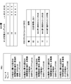
端末装置1により使用されるCSIを報告する時間及び周波数リソースは、基地局装置3により制御される。CSIは、CQI(Channel Quality Indicator)、PMI(Precoding Matrix Indicator)、CRI(CSI-RS Resource Indicator)、SLI(Strongest Layer Indication)、RI(rank indication)および/またはL1-RSRP(Layer-1Reference Signal Received Power)を含む。CQI、PMI、CRI、SLI、RI、L1-RSRPのために、端末装置1は、N(Nは1以上)のCSI報告に関する設定、M(Mは1以上)のCSI参照信号(CSI-RS)のリソースに関する設定、L(Lは1以上)のリンクを含む1つのCSI測定に関する設定を上位レイヤにより設定される。CSI測定に関する設定は、CSI報告に関する設定のリストと、CSIリソースに関する設定のリストと、リンクの設定のリストと、トリガ状態のリストを含む。以下、それぞれについて説明する。
The time and frequency resources for reporting CSI used by the terminal device 1 are controlled by the base station device 3. CSI is CQI (Channel Quality Indicator), PMI (Precoding Matrix Indicator), CRI (CSI-RS Resource Indicator), SLI (Strongest Layer Indication), RI (rank indication) and / or L1-RSRP (Layer-1 Reference Signal Received) Power) is included. For CQI, PMI, CRI, SLI, RI, L1-RSRP, the terminal device 1 sets N (N is 1 or more) CSI report, M (M is 1 or more) CSI reference signal (CSI-RS) The upper layer sets up the configuration related to one CSI measurement including the link related to L) and L (L is 1 or more). The configuration for CSI measurement includes a list of configurations for CSI reporting, a list of configurations for CSI resources, a list of link configurations, and a list of trigger states. Each of these will be described below.
CSI報告に関する設定の各々は、1つの下りリンクのBWP(上位レイヤのBWPアイデンティティ)に関連付けられ、CSI報告に関する設定の各々は、報告されるパラメータは以下のものを含む。
・CSI報告に関する設定を識別するための1つのアイデンティティ
・時間領域の動作(例えば、周期的(periodic)、セミパーシステント、または非周期(Aperiodic))
・報告されるCSIパラメータ(例えば、CRI、RI、PMI、CQIなど)
・周波数領域の設定(広帯域CQIまたはサブバンドCQIを設定する情報、広帯域PMIまたはサブバンドPMIを設定する情報がそれぞれ含まれる)
・CSI測定の制限の設定(measurement restriction configuration、チャネル測定と干渉測定のそれぞれに対して設定されてよい)
・コードブック設定(CSIのタイプ(タイプ1かタイプ2かを示す情報)とコードブックサブセット制限の設定)
・1報告あたりのCQIの最大数(1コードワードか2コードワードかを示す情報であってよい)
・CQIテーブルの想定(64QAMまでを含むCQIテーブル、256QAMまでを含むCQIテーブル、URLLCなど) Each of the settings for CSI reporting is associated with one downlink BWP (upper layer BWP identity), and for each setting for CSI reporting, the parameters to be reported include:
One identity time-domain operation (eg, periodic, semi-persistent, or aperiodic) to identify settings for CSI reporting
-Reported CSI parameters (eg CRI, RI, PMI, CQI etc)
・ Setting of frequency domain (information for setting wideband CQI or subband CQI, information for setting wideband PMI or subband PMI, respectively)
・ Setting of CSI measurement restriction (may be set for measurement restriction configuration, each of channel measurement and interference measurement)
Codebook setting (information indicating type of CSI (type 1 or type 2) and setting of codebook subset restriction)
・ Maximum number of CQIs per report (may be information indicating 1 codeword or 2 codewords)
・ Assumption of CQI table (CQI table including up to 64 QAM, CQI table including up to 256 QAM, URLLC, etc.)
・CSI報告に関する設定を識別するための1つのアイデンティティ
・時間領域の動作(例えば、周期的(periodic)、セミパーシステント、または非周期(Aperiodic))
・報告されるCSIパラメータ(例えば、CRI、RI、PMI、CQIなど)
・周波数領域の設定(広帯域CQIまたはサブバンドCQIを設定する情報、広帯域PMIまたはサブバンドPMIを設定する情報がそれぞれ含まれる)
・CSI測定の制限の設定(measurement restriction configuration、チャネル測定と干渉測定のそれぞれに対して設定されてよい)
・コードブック設定(CSIのタイプ(タイプ1かタイプ2かを示す情報)とコードブックサブセット制限の設定)
・1報告あたりのCQIの最大数(1コードワードか2コードワードかを示す情報であってよい)
・CQIテーブルの想定(64QAMまでを含むCQIテーブル、256QAMまでを含むCQIテーブル、URLLCなど) Each of the settings for CSI reporting is associated with one downlink BWP (upper layer BWP identity), and for each setting for CSI reporting, the parameters to be reported include:
One identity time-domain operation (eg, periodic, semi-persistent, or aperiodic) to identify settings for CSI reporting
-Reported CSI parameters (eg CRI, RI, PMI, CQI etc)
・ Setting of frequency domain (information for setting wideband CQI or subband CQI, information for setting wideband PMI or subband PMI, respectively)
・ Setting of CSI measurement restriction (may be set for measurement restriction configuration, each of channel measurement and interference measurement)
Codebook setting (information indicating type of CSI (
・ Maximum number of CQIs per report (may be information indicating 1 codeword or 2 codewords)
・ Assumption of CQI table (CQI table including up to 64 QAM, CQI table including up to 256 QAM, URLLC, etc.)
CSIリソースに関する設定の各々は、S(Sは1以上)のCSI-RSリソースセットに関する情報を含み、各CSI-RSリソースセットは、複数のCSI-RSリソース(チャネル測定または干渉測定のためのNZPCSI-RSと、干渉測定のためのCSI-IM(Interference Measurement)リソース)と、L1-RSRP計算のために使用されるSS/PBCHブロックのリソースに関する設定を含む。ここで、NZP CSI-RSリソースとは、予め仕様で定義された生成方法に従って系列が生成され、CSI-RSがマッピングされるリソースエレメントにマップされるCSI-RSである。また、CSIリソースに関する設定の各々は、上位レイヤで識別された(identified)BWPに置かれ、1つのCSI報告に関する設定に紐づけられたすべてのCSIリソースに関する設定は、同じBWPである。
Each configuration for CSI resources includes information on S (S is one or more) CSI-RS resource sets, and each CSI-RS resource set includes multiple CSI-RS resources (NZPCSI for channel measurement or interference measurement). -Includes settings for RS, CSI-IM (Interference Measurement resource for interference measurement), and resources of SS / PBCH block used for L1-RSRP calculation. Here, the NZP CSI-RS resource is a CSI-RS in which a sequence is generated in accordance with a generation method defined in advance in specifications and the CSI-RS is mapped to a resource element to be mapped. Also, each of the settings for CSI resources are placed in the identified BWP in the upper layer, and the settings for all CSI resources tied to the settings for one CSI report are the same BWP.
次に、上述のチャネル測定と干渉測定について説明する。チャネル測定は、CSI測定のために下りリンクの所望信号またはチャネルまたは空間多重を想定した場合の各レイヤまたは各コードワードの品質に関する量を測定することであり、干渉測定は、CSI測定のために下りリンクの干渉信号またチャネルまたは空間多重を想定した場合の各レイヤまたはコードワードにおける干渉の量を測定することである。ここでレイヤとは、空間多重されるPDSCHの数である。
Next, the above-mentioned channel measurement and interference measurement will be described. Channel measurement is to measure the quantity related to the quality of each layer or each codeword assuming downlink desired signal or channel or spatial multiplexing for CSI measurement, and interference measurement is for CSI measurement. It is to measure the amount of interference in each layer or codeword assuming downlink interference signals or channels or spatial multiplexing. Here, the layer is the number of PDSCHs spatially multiplexed.
なお、L1-RSRP計算のために使用されるSS/PBCHブロックのリソースに関する設定(ssb-Resources)は、CSIリソースに関する設定の各々に含まれてもよい。
In addition, the setting (ssb-Resources) regarding the resource of SS / PBCH block used for L1-RSRP calculation may be included in each of the setting regarding a CSI resource.
また、CSIリソースに関する設定の各々に、CSI―RSリソースの時間領域の動作が含まれてよい。また、各CSI-RSリソースセットに関する設定に、CSI―RSリソースの時間領域の動作が含まれてもよい。
Also, each of the configurations for CSI resources may include time domain behavior of CSI-RS resources. Also, the configuration for each CSI-RS resource set may include time domain operations of the CSI-RS resource.
各リンクの設定は、CSI報告に関する設定のインディケーションと、CSI設定のインディケーションと、チャネル測定か干渉測定のどちらを測定するかを示すインディケーションを含む。また、各リンクの設定は、1つまたは複数の非周期なCSI報告のためのCSI報告に関する設定を動的に選択するための複数のトリガ状態を含んでよい。
The setting of each link includes an indication of setting for CSI reporting, an indication of CSI setting, and an indication indicating whether to measure channel measurement or interference measurement. Also, the configuration of each link may include multiple trigger states for dynamically selecting the configuration for CSI reporting for one or more non-periodic CSI reporting.
各トリガ状態は、1つまたは複数のCSI報告に関する設定に関連付けられ、各CSI報告に関する設定は、1つまたは複数の周期的またはセミパーシステントまたは非周期のCSI参照信号に関する設定に紐づけられている。ここで、紐づけられたCSIリソースに関する設定の数により端末装置は下記を想定してよい。
・1つのCSIリソースに関する設定が設定された場合、そのリソース設定はL1-RSRP計算のためのチャネル測定のためである。
・2つのCSIリソースに関する設定が設定された場合、1つめのCSIリソースに関する設定はチャネル測定のためであり、2つめのCSIリソースに関する設定は、CSI-IMまたはNZP CSI-RSリソース上での干渉測定のためである。
・3つのCSIリソースに関する設定が設定された場合、1つめのCSIリソースに関する設定はチャネル測定のためであり、2つめのCSIリソースに関する設定は、CSI-IMリソース上での干渉測定のためであり、3つめのCSIリソースに関する設定はNZP CSI-RSリソース上での干渉測定のためである。 Each trigger state is associated with settings for one or more CSI reports, and settings for each CSI report are tied to settings for one or more periodic or semi-persistent or non-periodic CSI reference signals. There is. Here, the terminal device may assume the following according to the number of settings related to the linked CSI resource.
If the configuration for one CSI resource is configured, the resource configuration is for channel measurement for L1-RSRP calculation.
-When settings for two CSI resources are configured, the settings for the first CSI resource are for channel measurement, and the settings for the second CSI resource are interference on the CSI-IM or NZP CSI-RS resources. It is for measurement.
-When the settings for three CSI resources are configured, the settings for the first CSI resource are for channel measurement, and the settings for the second CSI resource are for interference measurement on the CSI-IM resource The configuration for the third CSI resource is for interference measurement on the NZP CSI-RS resource.
CSI測定のために、端末装置1は、下記を想定してよい。
・干渉測定のために設定された各NZP CSI-RSポートは干渉の送信レイヤに対応すること、
・NZP CSI-RSポート上のすべての干渉の送信レイヤが、関連付けられたEPRE(Energy per resource element)が考慮されていること、および
・チャネル測定のためのNZP CSI-RSリソース、または干渉測定のためのCSI-RSリソース、または干渉測定のためのCSI-IMリソース上に他の干渉信号があること Theterminal device 1 may assume the following for CSI measurement.
Each NZP CSI-RS port configured for interference measurement to correspond to the transmission layer of interference,
The transmission layer of all interference on the NZP CSI-RS port is taken into account the associated energy per resource element (EPRE), and the NZP CSI-RS resource for channel measurement, or of the interference measurement That there is another interference signal on the CSI-RS resource for the measurement or the CSI-IM resource for the interference measurement
・干渉測定のために設定された各NZP CSI-RSポートは干渉の送信レイヤに対応すること、
・NZP CSI-RSポート上のすべての干渉の送信レイヤが、関連付けられたEPRE(Energy per resource element)が考慮されていること、および
・チャネル測定のためのNZP CSI-RSリソース、または干渉測定のためのCSI-RSリソース、または干渉測定のためのCSI-IMリソース上に他の干渉信号があること The
Each NZP CSI-RS port configured for interference measurement to correspond to the transmission layer of interference,
The transmission layer of all interference on the NZP CSI-RS port is taken into account the associated energy per resource element (EPRE), and the NZP CSI-RS resource for channel measurement, or of the interference measurement That there is another interference signal on the CSI-RS resource for the measurement or the CSI-IM resource for the interference measurement
ここで、EPREは、リソースエレメントあたりのNZP CSI-RSのエネルギーを表す。具体的には、基地局装置3は、NZP CSI-RSのEPREに対するPDSCH EPREの比(Pc)、NZP CSI-RSのEPREに対するPDCCH EPREの比(Pc-PDCCH)、NZP CSI-RSのEPREに対するSS/PBCHブロックのEPREの比(Pc_SS)がそれぞれ設定される。これにより、CSI-RS EPREを設定されたエネルギーの比からCSI測定にEPREを考慮することができる。
Here, EPRE represents the energy of NZP CSI-RS per resource element. Specifically, the base station apparatus 3 may use the ratio of PDSCH EPRE to EPRE of NZP CSI-RS (Pc), the ratio of PDCCH EPRE to EPRE of NZP CSI-RS (Pc-PDCCH), the ratio of NZP CSI-RS to EPRE The EPRE ratio (Pc_SS) of the SS / PBCH block is set respectively. This allows the EPRE to be taken into account in the CSI measurement from the energy ratio set CSI-RS EPRE.
CSI-RSリソースセットの時間領域の動作が非周期であるCSI-RSリソースセットのために、1つまたは複数のコンポーネントキャリアでのチャネル測定および/または干渉測定のための1つまたは複数のCSI報告に関する設定および/または1つまたは複数のCSI-RSリソースセットのためのトリガ状態が上位レイヤで設定される。非周期のCSI報告のトリガのために、1つのCSIトリガ状態のセットが上位レイヤのパラメータで設定され、CSIトリガ状態は、DL BWPのいずれか1つの候補に関連付けられる。端末装置1は、活性化されていない下りリンクBWPのためのCSI報告をトリガされることを期待しない。各トリガ状態は、DCI(例えば、DCIフォーマット0_1)に含まれるCSIリクエストフィールドを用いて開始される。
One or more CSI reports for channel measurement and / or interference measurement on one or more component carriers for CSI-RS resource sets where the time domain behavior of the CSI-RS resource set is non-periodic And / or trigger conditions for one or more CSI-RS resource sets are set in the upper layer. For triggering of non-periodic CSI reporting, one set of CSI trigger states is configured in higher layer parameters and the CSI trigger states are associated with any one candidate of DL BWP. The terminal device 1 does not expect to be triggered CSI reporting for downlink BWPs that are not activated. Each trigger state is initiated using the CSI request field included in the DCI (eg, DCI format 0_1).
このとき、端末装置は、下記の動作を行う。
・CSIリクエストフィールドの値が0の場合、CSIはリクエストされない
・CSIトリガ状態の数が2NTS-1より大きい場合は、端末装置1はCSIリクエストフィールドのコードポイントに2NTS-1トリガ状態までマップするために使われる選択コマンドをMAC層から受信する。ただし、NTSは、上位レイヤで設定されるCSIリクエストフィールドのビットサイズである。NTSは、{0,1,2,3,4,5,6}の中からいずれかの値が設定されてよい。
・CSIトリガ状態の数が2NTS-1より小さいまたは等しい場合、CSIリクエストフィールドは直接トリガ状態と端末装置1のQCL想定を指示する。
・各CSIトリガ状態に関連付けられた非周期のCSI-RSリソースのために、端末装置1はQCLのソース参照信号とQCLタイプのQCL設定が上位レイヤより指示される(例えば、TCIを用いてもよい)。 At this time, the terminal device performs the following operation.
-If the value of the CSI request field is 0, CSI is not requested-If the number of CSI trigger states is larger than 2 NTS -1, theterminal device 1 maps the code point of the CSI request field to 2 NTS -1 trigger states. Receive from the MAC layer the selection command used to However, N TS is the bit size of the CSI request field set in the upper layer. N TS may be set to any value from {0, 1, 2, 3, 4, 5, 6}.
If the number of CSI trigger states is less than or equal to 2 NTS −1, the CSI request field directly indicates the trigger states and the QCL assumption of theterminal device 1.
-For non-periodic CSI-RS resources associated with each CSI trigger state, theterminal device 1 is instructed by the upper layer of the source reference signal of the QCL and the QCL type of the QCL type (for example, even using TCI) Good).
・CSIリクエストフィールドの値が0の場合、CSIはリクエストされない
・CSIトリガ状態の数が2NTS-1より大きい場合は、端末装置1はCSIリクエストフィールドのコードポイントに2NTS-1トリガ状態までマップするために使われる選択コマンドをMAC層から受信する。ただし、NTSは、上位レイヤで設定されるCSIリクエストフィールドのビットサイズである。NTSは、{0,1,2,3,4,5,6}の中からいずれかの値が設定されてよい。
・CSIトリガ状態の数が2NTS-1より小さいまたは等しい場合、CSIリクエストフィールドは直接トリガ状態と端末装置1のQCL想定を指示する。
・各CSIトリガ状態に関連付けられた非周期のCSI-RSリソースのために、端末装置1はQCLのソース参照信号とQCLタイプのQCL設定が上位レイヤより指示される(例えば、TCIを用いてもよい)。 At this time, the terminal device performs the following operation.
-If the value of the CSI request field is 0, CSI is not requested-If the number of CSI trigger states is larger than 2 NTS -1, the
If the number of CSI trigger states is less than or equal to 2 NTS −1, the CSI request field directly indicates the trigger states and the QCL assumption of the
-For non-periodic CSI-RS resources associated with each CSI trigger state, the
ここで、NTSはDCIのCSIリクエストフィールドのビット数であり、RRCで設定される非周期のCSI報告のためのトリガの状態の数(NCSI)は、2NTS-1よりも大きくても小さくても等しくてもよい。
Here, N TS is the number of bits in the CSI request field of DCI, and the number of trigger states (N CSI ) for aperiodic CSI reporting set in RRC is larger than 2 NTS -1 It may be smaller or equal.
もし、1つのCSI報告に関する設定に紐づけられたCSIリソースに関する設定が、複数の非周期なCSI-RSリソースセットに関する設定を持ち、非周期なCSI-RSリソースセットの一部のみがあるトリガ状態に関連付けられている場合、各CSI-RSリソースセット毎にトリガ状態ごとにCSI-IMリソースまたはNZP CSI-RSリソースセットを選択するためにビットマップが上位レイヤで設定される。
If the configuration related to the CSI resource linked to the configuration related to one CSI report has a configuration related to multiple non-periodic CSI-RS resource sets, there is a trigger state in which only part of the non-periodic CSI-RS resource set is present In the upper layer, a bitmap is configured to select a CSI-IM resource or an NZP CSI-RS resource set for each trigger state for each CSI-RS resource set.
上述の設定について説明する。セル毎に端末装置1に設定される情報(例えば、ServingCellConfigDedicated)に、CSI測定に関する情報が含まれてよい。即ち、CSI測定に関する情報は、セル毎に設定され、各セルのCSI測定に関する情報は下記の情報を含む。
・N個のCSI報告に関する設定のリスト
・M個のCSI参照信号に関する設定のリスト
・L個のCSI報告に関する設定とCSI参照信号に関する設定の間のリンクのリスト(csi-MeasIdToAddModList)
・CSI報告のトリガに関する情報(CSIリクエストフィールドのビット数NTSおよび/またはCSIリクエストフィールドの値に対応するトリガ状態) The above setting will be described. Information (for example, ServingCellConfigDedicated) set in theterminal device 1 for each cell may include information on CSI measurement. That is, the information on the CSI measurement is set for each cell, and the information on the CSI measurement of each cell includes the following information.
List of settings for N CSI reports List of settings for M CSI reference signals List of links between settings for L CSI reports and settings for CSI reference signals (csi-MeasIdToAddModList)
Information on the trigger of CSI report (number of bits of CSI request field N TS and / or trigger state corresponding to the value of CSI request field)
・N個のCSI報告に関する設定のリスト
・M個のCSI参照信号に関する設定のリスト
・L個のCSI報告に関する設定とCSI参照信号に関する設定の間のリンクのリスト(csi-MeasIdToAddModList)
・CSI報告のトリガに関する情報(CSIリクエストフィールドのビット数NTSおよび/またはCSIリクエストフィールドの値に対応するトリガ状態) The above setting will be described. Information (for example, ServingCellConfigDedicated) set in the
List of settings for N CSI reports List of settings for M CSI reference signals List of links between settings for L CSI reports and settings for CSI reference signals (csi-MeasIdToAddModList)
Information on the trigger of CSI report (number of bits of CSI request field N TS and / or trigger state corresponding to the value of CSI request field)
各CSI報告に関する設定には、CSI報告に関する設定のインデックスまたはアイデンティティ、時間領域の動作を設定する情報、どのCSIを報告するかを設定する情報を含む。また、1つのBWPを識別するためのBWPインデックスを含んでもよい。
The configuration for each CSI report includes a configuration index or identity for the CSI report, information for configuring time domain operation, and information for configuring which CSI to report. Also, it may include a BWP index for identifying one BWP.
時間領域の動作を設定する情報が周期的またはセミパーシステントを示す場合には、CSIを報告する周期(スロット数)が含まれてよい。時間領域の動作を設定する情報が非周期(Aperiodic)を示す場合、非周期CSI報告がトリガされたスロットからCSI報告を送信するまでのスロット数のオフセットに関する情報を含んでよい。また、時間領域の動作を設定する情報が非周期(Aperiodic)を示す場合、各CSI報告に関する設定がCSI報告のトリガ状態のインデックスを含んでよい。
If the information setting the time domain operation indicates periodic or semi-persistent, a period (number of slots) for reporting CSI may be included. When the information for setting the operation in the time domain indicates Aperiodic, the information on the offset of the number of slots from the slot in which the aperiodic CSI report is triggered to the transmission of the CSI report may be included. Also, when the information for setting the time domain operation indicates aperiodic, the setting for each CSI report may include an index of a CSI report trigger state.
各リンクに関する設定は、リンクされるCSI報告に関する設定のインデックスまたはアイデンティティとCSI参照信号に関する設定のインデックスまたはアイデンティティ、リンクのアイデンティティを含んでもよい。
The settings for each link may include the index of the setting for the linked CSI report or the index of the setting for the CSI reference signal or the identity of the link.
図6は、あるサービングセルcにおけるCSI測定に関するRRCの設定およびCSIリクエストフィールドの一例を示している。ここでは、RRCで設定されるトリガ状態の数NCSI=3、CSIリクエストフィールドのビット数NTS=2として説明する。なお、ここではサービングセルに設定されているBWPの数が2であるとしている。図6に示されるように、サービングセルcのCSI測定に関する情報に、CSI報告に関する設定のリストが設定されており、リスト内に、CSI報告に関する設定が4つ設定されている。そのうち、非周期なCSI報告の設定は、CSI報告に関する設定#1~#3である。
FIG. 6 shows an example of RRC configuration and CSI request field related to CSI measurement in a certain serving cell c. Here, it is assumed that the number of trigger states N CSI set in RRC = 3 and the number of bits of the CSI request field N TS = 2. Here, it is assumed that the number of BWPs set in the serving cell is two. As shown in FIG. 6, a list of settings for CSI reporting is set in the information on CSI measurement of the serving cell c, and four settings for CSI reporting are set in the list. Among them, the configuration of the non-periodic CSI report is configurations # 1 to # 3 related to the CSI report.
CSI報告に関する設定#1は、トリガ状態#0に関連付けられ、CSI報告に関する設定#2は、トリガ状態#1に関連付けられ、CSI報告に関する設定#3は、トリガ状態#2に関連付けられている。この場合、NCSI=2NTS-1なので、DCIフォーマットに含まれる2ビットのCSIリクエストフィールドに直接マップされる。図6に示されるように、CSIリクエストフィールドの“00”はCSI報告を送信しない。“01”にトリガ状態#0、“10”にトリガ状態#1、“11”にトリガ状態#2がそれぞれ関連付けられている。
Configuration # 1 for CSI report is associated with trigger state # 0, configuration # 2 for CSI report is associated with trigger state # 1, and configuration # 3 for CSI report is associated with trigger state # 2. In this case, since N CSI = 2 NTS -1, it is directly mapped to the 2-bit CSI request field included in the DCI format. As shown in FIG. 6, “00” in the CSI request field does not transmit a CSI report. The trigger state # 0 is associated with “01”, the trigger state # 1 is associated with “10”, and the trigger state # 2 is associated with “11”.
端末装置1は、RRCで設定されたCSI報告に関する設定と、DCIに含まれるCSIリクエストフィールドの値に基づいて関連付けられたCSI報告に関する設定に基づいて、CSIをPUSCHで報告する。このとき、端末装置1は、CSI報告に関する設定に関連付けられたCSIリソースに関する設定からCSIを測定するCSI-RSリソースセットまたはCSI-RSリソースから、CSI報告に関する設定に含まれる報告されるCSIパラメータに基づいてCSIを測定する。
The terminal device 1 reports CSI on PUSCH based on the configuration on the CSI report set in RRC and the configuration on the CSI report associated based on the value of the CSI request field included in the DCI. At this time, the terminal device 1 measures CSI from the setting regarding the CSI resource associated with the setting regarding the CSI report, from the CSI-RS resource set or the CSI-RS resource to the reported CSI parameter included in the setting regarding the CSI report Measure CSI based on it.
また、各CSI報告に関する設定は、サービングセル内のBWPと関連付けられている。図6において、トリガ状態#1およびトリガ状態#2は、BWPインデックス#0とBWPインデックス#1にそれぞれ関連付けられている。つまり、端末装置1は、CSIリクエストフィールドの値として10が指示された場合には、BWP#1におけるCSIを報告する。すなわち、CSIリクエストフィールドの値(情報)は複数のトリガ状態のうちの1つを示し、複数のトリガ状態の各々は、サービングセルごとに設定され、1つまたは複数のCSI報告の設定、および1つまたは複数のCSI測定のための参照信号に関する設定に関連付けられる。なお、CSIリクエストフィールドの値はCSIリクエストフィールドに含まれる情報と換言されてもよい。
Also, the configuration for each CSI report is associated with the BWP in the serving cell. In FIG. 6, trigger state # 1 and trigger state # 2 are associated with BWP index # 0 and BWP index # 1, respectively. That is, when 10 is indicated as the value of the CSI request field, the terminal device 1 reports CSI in BWP # 1. That is, the value (information) of the CSI request field indicates one of a plurality of trigger states, and each of the plurality of trigger states is set for each serving cell, one or more CSI report settings, and one Or associated with settings for reference signals for multiple CSI measurements. The value of the CSI request field may be replaced with information included in the CSI request field.
ここで、トリガ状態#0のBWPインデックスとして、設定されたBWPの実際のインデックスではなく“active”が設定されている。これは、活性化されたBWPと関連付けられていることを意味する。例えば、端末装置1に対して、あるスロットにおいてBWPインデックス#0を示すBWPが活性化されている場合、CSIリクエストフィールド“01”は活性化されているBWPインデックス#0に対応するBWPでCSIを測定し、CSIを報告する。一方、あるスロットにおいてBWPインデックス#1に対応するBWPが活性化されている場合、CSIリクエストフィールド“01”は活性化されているBWPインデックス#1に対応するBWPでCSIを測定し、CSIを報告する。すなわち、PDCCHのDCIに含まれるCSIリクエストフィールドは、トリガ状態を含み、各トリガ状態は1つまたは複数のCSI報告に関する設定および1つまたは複数のCSIリソースに関する設定に関連付けられ、複数のトリガ状態のうち1つの状態は、サービングセルcの活性化されたBWPに関連付けられるように設定される。
Here, as the BWP index of the trigger state # 0, "active" is set instead of the actual index of the set BWP. This means that it is associated with activated BWP. For example, when the BWP indicating the BWP index # 0 is activated in a certain slot for the terminal device 1, the CSI request field "01" is a CSI corresponding to the BWP corresponding to the activated BWP index # 0. Measure and report CSI. On the other hand, when the BWP corresponding to the BWP index # 1 is activated in a certain slot, the CSI request field "01" measures CSI by the BWP corresponding to the activated BWP index # 1 and reports the CSI. Do. That is, CSI request fields included in DCI of PDCCH include trigger states, each trigger state is associated with a configuration for one or more CSI reports and a configuration for one or more CSI resources, and the plurality of trigger states are One of the states is set to be associated with the activated BWP of the serving cell c.
図7に、あるサービングセルにおけるRRCで設定されるトリガ状態の数NCSI=4、CSIリクエストフィールドのビット数NTS=2とする場合の設定およびCSIリクエストフィールドの例を示す。図7の例も図6と同様に時間動作が非周期であるCSI報告に関する設定の各々は、BWPインデックスおよびトリガ状態が関連付けられている。
FIG. 7 shows an example of the setting and CSI request field in the case where the number of trigger states N CSI = 4 set in RRC in a serving cell and the number of bits N TS = 2 of the CSI request field. Similar to FIG. 6 in the example of FIG. 7, each setting for a CSI report whose time operation is aperiodic is associated with a BWP index and a trigger state.
図7の例では、NCSI>2NTS-1なので、MAC層を介してCSIリクエストフィールドの各コードポイント“01”、“10” 、“11”のためのトリガ状態が選択される。図7に示されるように、RRCで設定された4つのトリガ状態に対して、各コードポイントのために各トリガ状態を示すビットマップを用いて1つまたは複数のトリガ状態を選択してよい。図7の例では、コードポイント“01”に対して各トリガ状態の選択のための4ビットのビットマップ“1000”が端末装置1に指示され、CSIリクエストフィールド“01”に対応するようにマップされる。これは、CSIリクエストフィールドのコードポイント“01”にトリガ状態#0となることを意味している。このようにMAC層では各トリガ状態に対応するビットマップにより各コードポイントが選択される。すなわち、PDCCHのDCIに含まれるCSIリクエストフィールドは、トリガ状態を含み、各トリガ状態は1つまたは複数のCSI報告に関する設定および1つまたは複数のCSIリソースに関する設定に関連付けられる。CSIリクエストフィールドに関連付けられるトリガ状態は、MAC層においてビットマップを用いて複数のトリガ状態から1つまたは複数選択され、CSIリクエストフィールドの各コードポイントにマップされる。
In the example of FIG. 7, since N CSI > 2 NTS −1, the trigger state for each code point “01”, “10”, “11” of the CSI request field is selected via the MAC layer. As shown in FIG. 7, for the four trigger states set in RRC, one or more trigger states may be selected using a bitmap indicating each trigger state for each code point. In the example of FIG. 7, for the code point “01”, a 4-bit bitmap “1000” for selecting each trigger state is indicated to the terminal device 1 and the map is made to correspond to the CSI request field “01”. Be done. This means that the trigger state # 0 will be at code point "01" of the CSI request field. Thus, in the MAC layer, each code point is selected by the bit map corresponding to each trigger state. That is, the CSI request field included in the DCI of the PDCCH includes trigger states, and each trigger state is associated with a configuration for one or more CSI reports and a configuration for one or more CSI resources. The trigger state associated with the CSI request field is selected from a plurality of trigger states using a bit map in the MAC layer and mapped to each code point of the CSI request field.
図8は、2つのサービングセルが設定された場合の例を示す。ここでは、サービングセル数として2つが設定され、各セルで、非周期のCSI報告に関する設定にトリガ状態が割り当てられる例を示している。同図のように、CSIリクエストフィールドには複数のCSI報告に関する設定が関連付けられる。例えば、サービングセル#1のトリガ状態#1と、サービングセル#2のトリガ状態#1がコードポイント“01”に設定されている。
FIG. 8 shows an example where two serving cells are set. Here, an example is shown in which two are set as the number of serving cells, and in each cell, a trigger state is assigned to the setting regarding aperiodic CSI reporting. As shown in the figure, the CSI request field has settings associated with a plurality of CSI reports. For example, trigger state # 1 of serving cell # 1 and trigger state # 1 of serving cell # 2 are set to code point "01".
ここで、あるスロットにおいて、端末装置1に対してCSIリクエストフィールドの値として“10”が指示された場合、端末装置1はサービングセル#1のBWP#0のCSIと、サービングセル#2のBWP#0のCSIを報告する。このとき、サービングセル#1のBWP#0とサービングセル#2のBWP#0がともに活性化されている場合、端末装置1はサービングセル#1のBWP#0とサービングセル#2のBWP#0のCSIを報告する。
Here, when “10” is instructed as the value of the CSI request field to the terminal device 1 in a certain slot, the terminal device 1 receives CSI of BWP # 0 of serving cell # 1 and BWP # 0 of serving cell # 2 Report the CSI of At this time, when both BWP # 0 of serving cell # 1 and BWP # 0 of serving cell # 2 are activated, the terminal device 1 reports CSI of BWP # 0 of serving cell # 1 and BWP # 0 of serving cell # 2 Do.
また、サービングセル#1のBWP#0が活性化されており、サービングセル#2のBWP#0が活性化されていない場合、末装置1はサービングセル#1のBWP#0のCSIを報告する。このように、複数のサービングセルが設定され、CSIリクエストフィールドの値により指示された各サービングセルのCSI報告をする。すなわち、端末装置1は、CSIリクエストフィールドを含むDCIを運ぶPDCCHを受信し、CSIリクエストフィールドに基づいて複数のサービングセルにおけるBWPのCSI報告がトリガされた場合に、活性化されているBWPインデックスが示すBWPのみのCSI報告を送信する。このとき、CSIリクエストフィールドはトリガ状態を示し、トリガ状態は、複数の状態のうち1つを示す。複数の状態の各々の状態は、サービングセル毎に設定され、1つまたは複数のCSI報告に関する設定および1つまたは複数のCSIリソースに関する設定および各サービングセルにおけるBWPインデックスに関連付けられる。
Also, if BWP # 0 of serving cell # 1 is activated and BWP # 0 of serving cell # 2 is not activated, the remote device 1 reports CSI of BWP # 0 of serving cell # 1. In this manner, multiple serving cells are configured to report CSI of each serving cell indicated by the value of the CSI request field. That is, the terminal device 1 receives the PDCCH carrying DCI including the CSI request field, and indicates the activated BWP index when the CSI report of BWP in a plurality of serving cells is triggered based on the CSI request field. Send a BWP-only CSI report. At this time, the CSI request field indicates a trigger state, and the trigger state indicates one of a plurality of states. The state of each of the plurality of states is configured for each serving cell, and is associated with the configuration for one or more CSI reports and the configuration for one or more CSI resources and the BWP index in each serving cell.
ここで、上述の例ではCSIリクエストフィールドの1つの値に、1つのCSI報告に関する設定が設定されたが、複数のCSI報告が関連付けられるようにしてもよい。
Here, although the setting regarding one CSI report was set to one value of the CSI request field in the above-mentioned example, a plurality of CSI reports may be associated.
上述の例では、各サービングセルのCSI報告に関する設定がBWPインデックスに関する設定に常に関連付けられている場合を示したが、BWPが1つの場合には関連付ける情報が設定されなくてよい。この場合、サービングセルの帯域幅に基づいてCSI測定及びCSI報告を行ってよい。
Although the above-mentioned example showed the case where the setting about the CSI report of each serving cell was always linked with the setting about BWP index, in the case of one BWP, the information to associate may not be set. In this case, CSI measurement and CSI reporting may be performed based on the serving cell bandwidth.
また、上述ではBWPが活性化されているか否かに基づいてCSI報告を送信する例を記載したが、サービングセルが非活性化されている場合も、そのサービングセルにおけるCSI報告を送信せず、活性化されたサービングセルおよび/または活性化されたBWPのみのCSIを報告してもよい。
Also, although the example in which the CSI report is transmitted based on whether or not the BWP is activated has been described above, even when the serving cell is deactivated, the CSI report in the serving cell is not transmitted but activated. Only CSI of the serving cell and / or the activated BWP may be reported.
また、上述の例ではCSI報告に関する設定にトリガ状態のインデックスを示す情報を含んだが、CSI測定に関する設定がトリガ状態のリストを含み、各トリガ状態がどのCSI報告に関する設定を含むかが設定されてもよい。
Also, in the above example, the setting for CSI report includes information indicating the index of trigger state, but the setting for CSI measurement includes a list of trigger states, and it is set that each trigger state includes the setting for which CSI report It is also good.
すなわち、本発明では、端末装置1は、活性化されたサービングセルのCSIのみを報告してもよい。また、端末装置1は、BWPが設定されており、活性化されているセルの場合は、活性化されたBWPのCSIのみを報告してもよい。また、端末装置1は、非活性化されたサービングセルのCSIを報告しなくてよい。非活性化されているBWPのCSIを報告しなくてよい。また、CSI報告に関する設定に含まれるBWPインデックスはサービングセルごとに設定されてよく、BWPの特定にサービングセルインデックスとBWPインデックスを用いてよい。
That is, in the present invention, the terminal device 1 may report only CSI of the activated serving cell. In addition, in the case of a cell in which BWP is set and activated, the terminal device 1 may report only CSI of the activated BWP. Also, the terminal device 1 may not report the CSI of the inactive serving cell. It is not necessary to report CSI of BWP which has been deactivated. Also, the BWP index included in the configuration related to the CSI report may be set for each serving cell, and the serving cell index and the BWP index may be used to specify the BWP.
本実施形態の一態様は、LTEやLTE-A/LTE-A Proといった無線アクセス技術(RAT: Radio Access Technology)とのキャリアアグリゲーションまたはデュアルコネクティビティにおいてオペレーションされてもよい。このとき、一部またはすべてのセルまたはセルグループ、キャリアまたはキャリアグループ(例えば、プライマリセル(PCell: Primary Cell)、セカンダリセル(SCell: Secondary Cell)、プライマリセカンダリセル(PSCell)、MCG(Master Cell Group)、SCG(Secondary Cell Group)など)で用いられてもよい。また、単独でオペレーションするスタンドアローンで用いられてもよい。デュアルコネクティビティオペレーションにおいては、SpCell(Special Cell)は、MACエンティティがMCGに関連付けられているか、SCGに関連付けられているかに応じて、それぞれ、MCGのPCellまたは、SCGのPSCellと称する。デュアルコネクティビティオペレーションでなければ、SpCell(Special Cell)は、PCellと称する。SpCell(Special Cell)は、PUCCH送信と、競合ベースランダムアクセスをサポートする。
One aspect of this embodiment may be operated in carrier aggregation or dual connectivity with a radio access technology (RAT: Radio Access Technology) such as LTE and LTE-A / LTE-A Pro. At this time, part or all of the cells or cell groups, carriers or carrier groups (for example, Primary Cell (PCell: Primary Cell), Secondary Cell (SCell: Secondary Cell), Primary Secondary Cell (PSCell), MCG (Master Cell Group) , SCG (Secondary Cell Group), etc.). Also, it may be used in a stand alone operation. In dual connectivity operation, SpCell (Special Cell) is referred to as PCG of MCG or PSCell of SCG, depending on whether the MAC entity is associated with MCG or SCG, respectively. If it is not dual connectivity operation, SpCell (Special Cell) is called PCell. SpCell (Special Cell) supports PUCCH transmission and contention based random access.
以下、本実施形態における装置の構成について説明する。ここでは、下りリンクの無線伝送方式として、CP-OFDM、上りリンクの無線伝送方式としてCP-OFDMまたはDFTS-OFDM(SC-FDM)を適用する場合の例を示している。
Hereinafter, the configuration of the apparatus in the present embodiment will be described. Here, an example in the case of applying CP-OFDM as a downlink radio transmission scheme and CP-OFDM or DFTS-OFDM (SC-FDM) as an uplink radio transmission scheme is shown.
図9は、本実施形態の端末装置1の構成を示す概略ブロック図である。図示するように、端末装置1は、上位層処理部101、制御部103、受信部105、送信部107と送受信アンテナ109を含んで構成される。また、上位層処理部101は、無線リソース制御部1011、スケジューリング情報解釈部1013、および、チャネル状態情報(CSI)報告制御部1015を含んで構成される。また、受信部105は、復号化部1051、復調部1053、多重分離部1055、無線受信部1057と測定部1059を含んで構成される。また、送信部107は、符号化部1071、変調部1073、多重部1075、無線送信部1077と上りリンク参照信号生成部1079を含んで構成される。
FIG. 9 is a schematic block diagram showing the configuration of the terminal device 1 of the present embodiment. As illustrated, the terminal device 1 includes an upper layer processing unit 101, a control unit 103, a receiving unit 105, a transmitting unit 107, and a transmitting / receiving antenna 109. The upper layer processing unit 101 is configured to include a radio resource control unit 1011, a scheduling information interpretation unit 1013, and a channel state information (CSI) report control unit 1015. Further, the receiving unit 105 is configured to include a decoding unit 1051, a demodulation unit 1053, a demultiplexing unit 1055, a wireless reception unit 1057, and a measurement unit 1059. In addition, the transmission unit 107 includes an encoding unit 1071, a modulation unit 1073, a multiplexing unit 1075, a radio transmission unit 1077, and an uplink reference signal generation unit 1079.
上位層処理部101は、ユーザの操作等により生成された上りリンクデータ(トランスポートブロック)を、送信部107に出力する。また、上位層処理部101は、媒体アクセス制御(MAC: Medium Access Control)層、パケットデータ統合プロトコル(Packet Data Convergence Protocol: PDCP)層、無線リンク制御(Radio Link Control: RLC)層、無線リソース制御(Radio Resource Control: RRC)層の処理を行う。
Upper layer processing section 101 outputs uplink data (transport block) generated by a user operation or the like to transmitting section 107. Also, the upper layer processing unit 101 includes a Medium Access Control (MAC) layer, a Packet Data Convergence Protocol (PDCP) layer, a Radio Link Control (RLC) layer, and a radio resource control. (Radio Resource Control: RRC) layer processing is performed.
上位層処理部101が備える無線リソース制御部1011は、自装置の各種設定情報の管理をする。また、無線リソース制御部1011は、上りリンクの各チャネルに配置される情報を生成し、送信部107に出力する。
The radio resource control unit 1011 included in the upper layer processing unit 101 manages various setting information of the own apparatus. Also, the radio resource control unit 1011 generates information to be allocated to each uplink channel, and outputs the information to the transmission unit 107.
上位層処理部101が備えるスケジューリング情報解釈部1013は、受信部105を介して受信したDCI(スケジューリング情報)の解釈をし、前記DCIを解釈した結果に基づき、受信部105、および送信部107の制御を行うために制御情報を生成し、制御部103に出力する。
The scheduling information interpretation unit 1013 included in the upper layer processing unit 101 interprets DCI (scheduling information) received via the reception unit 105, and based on the result of interpreting the DCI, the scheduling information interpretation unit 1013 of the reception unit 105 and transmission unit 107 Control information is generated to perform control, and is output to the control unit 103.
CSI報告制御部1015は、測定部1059に、CSI参照リソースに関連するチャネル状態情報(RI/PMI/CQI/CRI)を導き出すよう指示する。CSI報告制御部1015は、送信部107に、RI/PMI/CQI/CRIを送信するよう指示をする。CSI報告制御部1015は、測定部1059がCQIを算出する際に用いる設定をセットする。
The CSI report control unit 1015 instructs the measurement unit 1059 to derive channel state information (RI / PMI / CQI / CRI) related to the CSI reference resource. The CSI report control unit 1015 instructs the transmission unit 107 to transmit RI / PMI / CQI / CRI. The CSI report control unit 1015 sets the setting used when the measurement unit 1059 calculates the CQI.
制御部103は、上位層処理部101からの制御情報に基づいて、受信部105、および送信部107の制御を行う制御信号を生成する。制御部103は、生成した制御信号を受信部105、および送信部107に出力して受信部105、および送信部107の制御を行う。
The control unit 103 generates a control signal that controls the reception unit 105 and the transmission unit 107 based on the control information from the upper layer processing unit 101. The control unit 103 outputs the generated control signal to the receiving unit 105 and the transmitting unit 107 to control the receiving unit 105 and the transmitting unit 107.
受信部105は、制御部103から入力された制御信号に従って、送受信アンテナ109を介して基地局装置3から受信した受信信号を、分離、復調、復号し、復号した情報を上位層処理部101に出力する。
Receiving section 105 separates, demodulates and decodes the received signal received from base station apparatus 3 via transmitting / receiving antenna 109 in accordance with the control signal input from control section 103, and transmits the decoded information to upper layer processing section 101. Output.
無線受信部1057は、送受信アンテナ109を介して受信した下りリンクの信号を、中間周波数に変換し(ダウンコンバート: down covert)、不要な周波数成分を除去し、信号レベルが適切に維持されるように増幅レベルを制御し、受信した信号の同相成分および直交成分に基づいて、直交復調し、直交復調されたアナログ信号をディジタル信号に変換する。無線受信部1057は、変換したディジタル信号からガードインターバル(Guard Interval: GI)に相当する部分を除去し、ガードインターバルを除去した信号に対して高速フーリエ変換(Fast Fourier Transform: FFT)を行い、周波数領域の信号を抽出する。
The wireless reception unit 1057 converts the downlink signal received via the transmission / reception antenna 109 into an intermediate frequency (down conversion: down cover), removes unnecessary frequency components, and maintains the signal level appropriately. Control the amplification level, and perform quadrature demodulation and convert the quadrature demodulated analog signal into a digital signal based on the in-phase component and the quadrature component of the received signal. The wireless reception unit 1057 removes a portion corresponding to a guard interval (GI) from the converted digital signal, performs fast Fourier transform (FFT) on the signal from which the guard interval has been removed, and Extract the region signal.
多重分離部1055は、抽出した信号を下りリンクのPDCCH、PDSCH、および下りリンク参照信号に、それぞれ分離する。また、多重分離部1055は、測定部1059から入力された伝搬路の推定値から、PDCCHおよびPUSCHの伝搬路の補償を行う。また、多重分離部1055は、分離した下りリンク参照信号を測定部1059に出力する。
The demultiplexing unit 1055 demultiplexes the extracted signal into downlink PDCCH, PDSCH, and downlink reference signal. Further, the demultiplexing unit 1055 compensates for the PDCCH and PUSCH propagation paths from the estimation value of the propagation path input from the measurement unit 1059. In addition, the demultiplexing unit 1055 outputs the demultiplexed downlink reference signal to the measuring unit 1059.
復調部1053は、下りリンクのPDCCHに対して、復調を行い、復号化部1051へ出力する。復号化部1051は、PDCCHの復号を試み、復号に成功した場合、復号した下りリンク制御情報と下りリンク制御情報が対応するRNTIとを上位層処理部101に出力する。
Demodulation section 1053 demodulates the downlink PDCCH, and outputs the result to decoding section 1051. Decoding section 1051 tries to decode PDCCH, and when decoding is successful, outputs the decoded downlink control information and the RNTI corresponding to the downlink control information to upper layer processing section 101.
復調部1053は、PDSCHに対して、QPSK(Quadrature Phase Shift Keying)、16QAM(Quadrature Amplitude Modulation)、64QAM、256QAM等の下りリンクグラントで通知された変調方式の復調を行い、復号化部1051へ出力する。復号化部1051は、下りリンク制御情報で通知された伝送または原符号化率に関する情報に基づいて復号を行い、復号した下りリンクデータ(トランスポートブロック)を上位層処理部101へ出力する。
Demodulation section 1053 demodulates the modulation scheme notified by downlink grant such as QPSK (Quadrature Phase Shift Keying), 16 QAM (Quadrature Amplitude Modulation), 64 QAM, 256 QAM, etc., for PDSCH, and outputs the result to decoding section 1051. Do. Decoding section 1051 performs decoding based on the information on transmission or original coding rate notified by the downlink control information, and outputs the decoded downlink data (transport block) to upper layer processing section 101.
測定部1059は、多重分離部1055から入力された下りリンク参照信号から、下りリンクのパスロスの測定、チャネル測定、および/または、干渉測定を行う。測定部1059は、測定結果に基づいて算出したCSI、および、測定結果を上位層処理部101へ出力する。また、測定部1059は、下りリンク参照信号から下りリンクの伝搬路の推定値を算出し、多重分離部1055へ出力する。
The measurement unit 1059 performs downlink path loss measurement, channel measurement, and / or interference measurement from the downlink reference signal input from the demultiplexing unit 1055. The measurement unit 1059 outputs the CSI calculated based on the measurement result and the measurement result to the upper layer processing unit 101. In addition, measurement section 1059 calculates the estimated value of the downlink propagation path from the downlink reference signal, and outputs this to demultiplexing section 1055.
送信部107は、制御部103から入力された制御信号に従って、上りリンク参照信号を生成し、上位層処理部101から入力された上りリンクデータ(トランスポートブロック)を符号化および変調し、PUCCH、PUSCH、および生成した上りリンク参照信号を多重し、送受信アンテナ109を介して基地局装置3に送信する。
The transmitting unit 107 generates an uplink reference signal according to the control signal input from the control unit 103, and encodes and modulates uplink data (transport block) input from the upper layer processing unit 101, thereby generating PUCCH, The PUSCH and the generated uplink reference signal are multiplexed and transmitted to the base station apparatus 3 via the transmission / reception antenna 109.
符号化部1071は、上位層処理部101から入力された上りリンク制御情報、および、上りリンクデータを符号化する。変調部1073は、符号化部1071から入力された符号化ビットをBPSK、QPSK、16QAM、64QAM、256QAM等の変調方式で変調する。
The encoding unit 1071 encodes uplink control information and uplink data input from the upper layer processing unit 101. The modulation unit 1073 modulates the coded bits input from the coding unit 1071 according to a modulation scheme such as BPSK, QPSK, 16 QAM, 64 QAM, 256 QAM, and the like.
上りリンク参照信号生成部1079は、基地局装置3を識別するための物理セル識別子(physical cell identity: PCI、Cell IDなどと称する。)、上りリンク参照信号を配置する帯域幅、上りリンクグラントで通知されたサイクリックシフト、DMRSシーケンスの生成に対するパラメータの値などを基に、予め定められた規則(式)で求まる系列を生成する。
The uplink reference signal generation unit 1079 is a physical cell identifier (physical cell identity: referred to as PCI, Cell ID, etc.) for identifying the base station apparatus 3, a bandwidth for arranging the uplink reference signal, and an uplink grant. Based on the notified cyclic shift, the value of the parameter for generation of the DMRS sequence, and the like, a sequence determined by a predetermined rule (expression) is generated.
多重部1075は、PUSCHのスケジューリングに用いられる情報に基づき、空間多重されるPUSCHのレイヤの数を決定し、MIMO空間多重(MIMO SM: Multiple Input Multiple Output Spatial Multiplexing)を用いることにより同一のPUSCHで送信される複数の上りリンクデータを、複数のレイヤにマッピングし、このレイヤに対してプレコーディング(precoding)を行う。
Multiplexing section 1075 determines the number of PUSCH layers to be spatially multiplexed based on the information used for PUSCH scheduling, and by using MIMO Multiplexing (MIMO SM: Multiple Input Multiple Output Spatial Multiplexing), the same PUSCH can be used. A plurality of uplink data to be transmitted are mapped to a plurality of layers, and precoding is performed on the layers.
多重部1075は、制御部103から入力された制御信号に従って、PUSCHの変調シンボルを離散フーリエ変換(Discrete Fourier Transform: DFT)する。また、多重部1075は、PUCCHおよび/またはPUSCHの信号と生成した上りリンク参照信号を送信アンテナポート毎に多重する。つまり、多重部1075は、PUCCHおよび/またはPUSCHの信号と生成した上りリンク参照信号を送信アンテナポート毎にリソースエレメントに配置する。
The multiplexing unit 1075 performs discrete Fourier transform (DFT) on modulation symbols of the PUSCH in accordance with the control signal input from the control unit 103. Also, the multiplexing unit 1075 multiplexes the PUCCH and / or PUSCH signal and the generated uplink reference signal for each transmission antenna port. That is, multiplexing section 1075 arranges the PUCCH and / or PUSCH signal and the generated uplink reference signal in the resource element for each transmission antenna port.
無線送信部1077は、多重された信号を逆高速フーリエ変換(Inverse Fast FourierTransform: IFFT)して、SC-FDM方式の変調を行い、SC-FDM変調されたSC-FDMシンボルにガードインターバルを付加し、ベースバンドのディジタル信号を生成し、ベースバンドのディジタル信号をアナログ信号に変換し、アナログ信号から中間周波数の同相成分および直交成分を生成し、中間周波数帯域に対する余分な周波数成分を除去し、中間周波数の信号を高周波数の信号に変換(アップコンバート: up convert)し、余分な周波数成分を除去し、電力増幅し、送受信アンテナ109に出力して送信する。
The wireless transmission unit 1077 performs Inverse Fast Fourier Transform (IFFT) on the multiplexed signal to perform modulation in the SC-FDM system, and adds a guard interval to the SC-FDM modulated SC-FDM symbol. , Generate a baseband digital signal, convert the baseband digital signal to an analog signal, generate an intermediate frequency in-phase component and a quadrature component from the analog signal, remove an extra frequency component for the intermediate frequency band, and A signal of frequency is converted (up converted) to a signal of high frequency, extra frequency components are removed, power is amplified, and the signal is output to the transmitting and receiving antenna 109 for transmission.
図10は、本実施形態の基地局装置3の構成を示す概略ブロック図である。図示するように、基地局装置3は、上位層処理部301、制御部303、受信部305、送信部307、および、送受信アンテナ309、を含んで構成される。また、上位層処理部301は、無線リソース制御部3011、スケジューリング部3013、および、CSI報告制御部3015を含んで構成される。また、受信部305は、復号化部3051、復調部3053、多重分離部3055、無線受信部3057と測定部3059を含んで構成される。また、送信部307は、符号化部3071、変調部3073、多重部3075、無線送信部3077と下りリンク参照信号生成部3079を含んで構成される。
FIG. 10 is a schematic block diagram showing the configuration of the base station device 3 of the present embodiment. As illustrated, the base station device 3 includes an upper layer processing unit 301, a control unit 303, a receiving unit 305, a transmitting unit 307, and a transmitting / receiving antenna 309. In addition, the upper layer processing unit 301 includes a radio resource control unit 3011, a scheduling unit 3013, and a CSI report control unit 3015. Further, the receiving unit 305 includes a decoding unit 3051, a demodulation unit 3053, a demultiplexing unit 3055, a wireless reception unit 3057, and a measurement unit 3059. Also, the transmitting unit 307 is configured to include an encoding unit 3071, a modulation unit 3073, a multiplexing unit 3075, a wireless transmission unit 3077, and a downlink reference signal generation unit 3079.
上位層処理部301は、媒体アクセス制御(MAC: Medium Access Control)層、パケットデータ統合プロトコル(Packet Data Convergence Protocol: PDCP)層、無線リンク制御(Radio Link Control: RLC)層、無線リソース制御(Radio Resource Control: RRC)層の処理を行う。また、上位層処理部301は、受信部305、および送信部307の制御を行うために制御情報を生成し、制御部303に出力する。
The upper layer processing unit 301 includes a Medium Access Control (MAC) layer, a Packet Data Convergence Protocol (PDCP) layer, a Radio Link Control (RLC) layer, and a Radio Resource Control (Radio Resource Control). Resource Control (RRC) layer processing is performed. Also, the upper layer processing unit 301 generates control information to control the receiving unit 305 and the transmitting unit 307, and outputs the control information to the control unit 303.
上位層処理部301が備える無線リソース制御部3011は、下りリンクのPDSCHに配置される下りリンクデータ(トランスポートブロック)、システムインフォメーション、RRCメッセージ、MAC CE(Control Element)などを生成し、又は上位ノードから取得し、送信部307に出力する。また、無線リソース制御部3011は、端末装置1各々の各種設定情報の管理をする。
The radio resource control unit 3011 included in the upper layer processing unit 301 generates downlink data (transport block), system information, RRC message, MAC CE (Control Element), etc. allocated to the downlink PDSCH, or It is acquired from the node and output to the transmitting unit 307. Also, the wireless resource control unit 3011 manages various setting information of each terminal device 1.
上位層処理部301が備えるスケジューリング部3013は、受信したCSIおよび測定部3059から入力された伝搬路の推定値やチャネルの品質などから、物理チャネル(PDSCHまたはPUSCH)を割り当てる周波数およびサブフレーム、物理チャネル(PDSCHまたはPUSCH)の伝送符号化率および変調方式および送信電力などを決定する。スケジューリング部3013は、スケジューリング結果に基づき、受信部305、および送信部307の制御を行うために制御情報を生成し、制御部303に出力する。スケジューリング部3013は、スケジューリング結果に基づき、物理チャネル(PDSCHまたはPUSCH)のスケジューリングに用いられる情報(例えば、DCI(フォーマット))を生成する。
The scheduling unit 3013 included in the upper layer processing unit 301 is configured to assign a physical channel (PDSCH or PUSCH) according to the received CSI and the channel estimation value or channel quality input from the measurement unit 3059, physical and so on, physical The transmission coding rate and modulation scheme and transmission power of the channel (PDSCH or PUSCH) are determined. The scheduling unit 3013 generates control information to control the reception unit 305 and the transmission unit 307 based on the scheduling result, and outputs the control information to the control unit 303. The scheduling unit 3013 generates information (for example, DCI (format)) used for scheduling of the physical channel (PDSCH or PUSCH) based on the scheduling result.
上位層処理部301が備えるCSI報告制御部3015は、端末装置1のCSI報告を制御する。CSI報告制御部3015は、端末装置1がCSI参照リソースにおいてRI/PMI/CQIを導き出すために想定する、各種設定を示す情報を、送信部307を介して、端末装置1に送信する。
The CSI report control unit 3015 included in the upper layer processing unit 301 controls the CSI report of the terminal device 1. The CSI report control unit 3015 transmits information indicating various settings, which is assumed for the terminal device 1 to derive RI / PMI / CQI in the CSI reference resource, to the terminal device 1 via the transmitting unit 307.
制御部303は、上位層処理部301からの制御情報に基づいて、受信部305、および送信部307の制御を行う制御信号を生成する。制御部303は、生成した制御信号を受信部305、および送信部307に出力して受信部305、および送信部307の制御を行う。
The control unit 303 generates a control signal for controlling the reception unit 305 and the transmission unit 307 based on the control information from the upper layer processing unit 301. The control unit 303 outputs the generated control signal to the receiving unit 305 and the transmitting unit 307 to control the receiving unit 305 and the transmitting unit 307.
受信部305は、制御部303から入力された制御信号に従って、送受信アンテナ309を介して端末装置1から受信した受信信号を分離、復調、復号し、復号した情報を上位層処理部301に出力する。無線受信部3057は、送受信アンテナ309を介して受信された上りリンクの信号を、中間周波数に変換し(ダウンコンバート: down covert)、不要な周波数成分を除去し、信号レベルが適切に維持されるように増幅レベルを制御し、受信された信号の同相成分および直交成分に基づいて、直交復調し、直交復調されたアナログ信号をディジタル信号に変換する。
The receiving unit 305 separates, demodulates and decodes the received signal received from the terminal device 1 via the transmitting and receiving antenna 309 according to the control signal input from the control unit 303, and outputs the decoded information to the upper layer processing unit 301. . The wireless reception unit 3057 converts the uplink signal received via the transmission / reception antenna 309 into an intermediate frequency (down conversion: down cover), removes unnecessary frequency components, and the signal level is appropriately maintained. Thus, the amplification level is controlled, and quadrature demodulation is performed based on the in-phase component and the quadrature component of the received signal, and the quadrature-demodulated analog signal is converted into a digital signal.
無線受信部3057は、変換したディジタル信号からガードインターバル(Guard Interval: GI)に相当する部分を除去する。無線受信部3057は、ガードインターバルを除去した信号に対して高速フーリエ変換(Fast Fourier Transform: FFT)を行い、周波数領域の信号を抽出し多重分離部3055に出力する。
The wireless reception unit 3057 removes a portion corresponding to a guard interval (GI) from the converted digital signal. The wireless reception unit 3057 performs fast Fourier transform (FFT) on the signal from which the guard interval has been removed, extracts a signal in the frequency domain, and outputs the signal to the demultiplexing unit 3055.
多重分離部1055は、無線受信部3057から入力された信号をPUCCH、PUSCH、上りリンク参照信号などの信号に分離する。尚、この分離は、予め基地局装置3が無線リソース制御部3011で決定し、各端末装置1に通知した上りリンクグラントに含まれる無線リソースの割り当て情報に基づいて行われる。また、多重分離部3055は、測定部3059から入力された伝搬路の推定値から、PUCCHとPUSCHの伝搬路の補償を行う。また、多重分離部3055は、分離した上りリンク参照信号を測定部3059に出力する。
The demultiplexing unit 1055 demultiplexes the signal input from the wireless reception unit 3057 into signals such as PUCCH, PUSCH, and uplink reference signal. This separation is performed based on the allocation information of the radio resource included in the uplink grant which the base station apparatus 3 has determined in advance by the radio resource control unit 3011 and notified to each terminal apparatus 1. Further, the demultiplexing unit 3055 compensates for the PUCCH and PUSCH propagation paths from the propagation path estimated value input from the measurement unit 3059. Further, the demultiplexing unit 3055 outputs the demultiplexed uplink reference signal to the measuring unit 3059.
復調部3053は、PUSCHを逆離散フーリエ変換(Inverse Discrete Fourier Transform: IDFT)し、変調シンボルを取得し、PUCCHとPUSCHの変調シンボルそれぞれに対して、BPSK(Binary Phase Shift Keying)、QPSK、16QAM、64QAM、256QAM等の予め定められた、または自装置が端末装置1各々に上りリンクグラントで予め通知した変調方式を用いて受信信号の復調を行う。復調部3053は、端末装置1各々に上りリンクグラントで予め通知した空間多重される系列の数と、この系列に対して行うプリコーディングを指示する情報に基づいて、MIMO SMを用いることにより同一のPUSCHで送信された複数の上りリンクデータの変調シンボルを分離する。
The demodulation unit 3053 performs inverse discrete Fourier transform (Inverse Discrete Fourier Transform: IDFT) on the PUSCH to obtain modulation symbols, and for each of PUCCH and PUSCH modulation symbols, Binary Phase Shift Keying (BPSK), QPSK, 16 QAM, The received signal is demodulated using a modulation scheme such as 64 QAM, 256 QAM, or the like, which has been predetermined or notified to the terminal device 1 in advance by the uplink grant. Demodulation section 3053 uses the MIMO SM based on the number of spatially multiplexed sequences notified in advance by uplink grant to each terminal apparatus 1 and information instructing precoding to be performed on this sequence. Separate modulation symbols of uplink data transmitted on PUSCH.
復号化部3051は、復調されたPUCCHとPUSCHの符号化ビットを、予め定められた符号化方式の、予め定められた、又は自装置が端末装置1に上りリンクグラントで予め通知した伝送または原符号化率で復号を行い、復号した上りリンクデータと、上りリンク制御情報を上位層処理部101へ出力する。PUSCHが再送信の場合は、復号化部3051は、上位層処理部301から入力されるHARQバッファに保持している符号化ビットと、復調された符号化ビットを用いて復号を行う。測定部3059は、多重分離部3055から入力された上りリンク参照信号から伝搬路の推定値、チャネルの品質などを測定し、多重分離部3055および上位層処理部301に出力する。
The decoding unit 3051 performs transmission or original notification of the decoded PUCCH and PUSCH coded bits in advance according to a predetermined coding scheme, or in which the own apparatus has notified the terminal apparatus 1 with an uplink grant in advance. Decoding is performed at the coding rate, and the decoded uplink data and uplink control information are output to upper layer processing section 101. When the PUSCH is retransmission, the decoding unit 3051 performs decoding using the coded bits held in the HARQ buffer input from the upper layer processing unit 301 and the decoded coded bits. The measuring unit 3059 measures the channel estimation value, channel quality, and the like from the uplink reference signal input from the demultiplexing unit 3055, and outputs the measured value to the demultiplexing unit 3055 and the upper layer processing unit 301.
送信部307は、制御部303から入力された制御信号に従って、下りリンク参照信号を生成し、上位層処理部301から入力された下りリンク制御情報、下りリンクデータを符号化、および変調し、PDCCH、PDSCH、および下りリンク参照信号を多重または別々の無線リソースで、送受信アンテナ309を介して端末装置1に信号を送信する。
The transmitting unit 307 generates a downlink reference signal in accordance with the control signal input from the control unit 303, and encodes and modulates the downlink control information and downlink data input from the upper layer processing unit 301 to generate a PDCCH. , PDSCH, and the downlink reference signal are transmitted to the terminal device 1 via the transmission / reception antenna 309 by multiplexing or on different radio resources.
符号化部3071は、上位層処理部301から入力された下りリンク制御情報、および下りリンクデータを符号化する。変調部3073は、符号化部3071から入力された符号化ビットをBPSK、QPSK、16QAM、64QAM、256QAM等の変調方式で変調する。
The encoding unit 3071 encodes downlink control information and downlink data input from the upper layer processing unit 301. The modulation unit 3073 modulates the coded bits input from the coding unit 3071 according to a modulation scheme such as BPSK, QPSK, 16 QAM, 64 QAM, 256 QAM, and the like.
下りリンク参照信号生成部3079は、基地局装置3を識別するための物理セル識別子(PCI)などを基に予め定められた規則で求まる、端末装置1が既知の系列を下りリンク参照信号として生成する。
The downlink reference signal generation unit 3079 generates a known sequence as the downlink reference signal by the terminal device 1, which is determined according to a predetermined rule based on a physical cell identifier (PCI) or the like for identifying the base station device 3. Do.
多重部3075は、空間多重されるPDSCHのレイヤの数に応じて、1つのPDSCHで送信される1つまたは複数の下りリンクデータを、1つまたは複数のレイヤにマッピングし、該1つまたは複数のレイヤに対してプレコーディング(precoding)を行う。多重部3075は、下りリンク物理チャネルの信号と下りリンク参照信号を送信アンテナポート毎に多重する。多重部3075は、送信アンテナポート毎に、下りリンク物理チャネルの信号と下りリンク参照信号をリソースエレメントに配置する。
The multiplexing unit 3075 maps one or more downlink data transmitted in one PDSCH to one or more layers according to the number of PDSCH layers to be spatially multiplexed, and the one or more Perform precoding on the layer of. The multiplexing unit 3075 multiplexes the downlink physical channel signal and the downlink reference signal for each transmission antenna port. The multiplexing unit 3075 arranges the downlink physical channel signal and the downlink reference signal in resource elements for each transmission antenna port.
無線送信部3077は、多重された変調シンボルなどを逆高速フーリエ変換(Inverse Fast Fourier Transform: IFFT)して、OFDM方式の変調を行い、OFDM変調されたOFDMシンボルにガードインターバルを付加し、ベースバンドのディジタル信号を生成し、ベースバンドのディジタル信号をアナログ信号に変換し、アナログ信号から中間周波数の同相成分および直交成分を生成し、中間周波数帯域に対する余分な周波数成分を除去し、中間周波数の信号を高周波数の信号に変換(アップコンバート: up convert)し、余分な周波数成分を除去し、電力増幅し、送受信アンテナ309に出力して送信する。
The wireless transmission unit 3077 performs inverse fast Fourier transform (IFFT) on the multiplexed modulation symbol etc. to perform modulation of the OFDM scheme, adds a guard interval to the OFDM modulated OFDM symbol, and performs baseband processing. Generate a digital signal of baseband, convert the digital signal of baseband to an analog signal, generate an in-phase component and a quadrature component of an intermediate frequency from the analog signal, remove an extra frequency component for an intermediate frequency band, and generate an intermediate frequency signal Is converted to a high frequency signal (up convert: up convert), extra frequency components are removed, power is amplified, and output to the transmit / receive antenna 309 for transmission.
(1)より具体的には、本発明の第1の態様における端末装置1は、第1の情報フィールドを含む下りリンク制御情報を運ぶ物理下りリンク制御チャネルを受信する受信部と、チャネル状態情報(CSI)を報告する送信部と、を備え、第1の情報フィールドは、第1の情報を示し、前記第1の情報は、複数の状態の内の一つを示し、前記複数の状態の各々の状態は、サービングセルごとに設定され、1つまたは複数のCSI報告の設定、1つまたは複数のCSI測定のための参照信号に関する設定、および、各サービングセルにおける帯域部分(BWP)インデックスに関連付けられ、複数のサービングセルにおけるBWPのCSI報告がトリガされた場合に、活性化されているBWPインデックスが示すBWPのみのCSI報告を送信する。
(1) More specifically, the terminal device 1 in the first aspect of the present invention is a receiver that receives a physical downlink control channel carrying downlink control information including a first information field, and channel state information A transmitter configured to report (CSI), the first information field indicates first information, the first information indicates one of a plurality of states, and the plurality of states are Each state is set for each serving cell and is associated with one or more CSI report settings, settings for reference signals for one or more CSI measurements, and a Band Part (BWP) index in each serving cell. , When a BWP CSI report is triggered in a plurality of serving cells, it transmits only the BWP CSI report indicated by the activated BWP index. .
(2)本発明の第2の態様における基地局装置3は、第1の情報フィールドを含む下りリンク制御情報を運ぶ物理下りリンク制御チャネルを送信する送信部と、チャネル状態情報(CSI)報告を受信する受信部と、を備え、第1の情報フィールドは、第1の情報を示し、前記第1の情報は、複数の状態の内の一つを示し、前記複数の状態の各々の状態は、サービングセルごとに設定され、1つまたは複数のCSI報告の設定、1つまたは複数のCSI測定のための参照信号に関する設定、および、各サービングセルにおける帯域部分(BWP)インデックスに関連付けられ、複数のサービングセルにおけるBWPのCSI報告がトリガされた場合に、活性化されているBWPインデックスが示すBWPのみのCSI報告を受信する。
(2) The base station apparatus 3 according to the second aspect of the present invention includes a transmitter configured to transmit a physical downlink control channel carrying downlink control information including the first information field, and a channel state information (CSI) report. A receiving unit for receiving, the first information field indicates first information, the first information indicates one of a plurality of states, and each state of the plurality of states is , Configuration for each serving cell, configuration for one or more CSI reports, configuration for reference signals for one or more CSI measurements, and a plurality of serving cells associated with a partial bandwidth (BWP) index in each serving cell When the BWP CSI report in B is triggered, only the BWP CSI report indicated by the activated BWP index is received.
(3)本発明の第3の態様における通信方法は、端末装置の通信方法であって、第1の情報フィールドを含む下りリンク制御情報を運ぶ物理下りリンク制御チャネルを受信し、チャネル状態情報(CSI)を報告し、第1の情報フィールドは、第1の情報を示し、前記第1の情報は、複数の状態の内の一つを示し、前記複数の状態の各々の状態は、サービングセルごとに設定され、1つまたは複数のCSI報告の設定、1つまたは複数のCSI測定のための参照信号に関する設定、および、各サービングセルにおける帯域部分(BWP)インデックスに関連付けられ、複数のサービングセルにおけるBWPのCSI報告がトリガされた場合に、活性化されているBWPインデックスが示すBWPのみのCSI報告を送信する。
(3) The communication method according to the third aspect of the present invention is a communication method of a terminal apparatus, comprising: receiving a physical downlink control channel carrying downlink control information including a first information field; A first information field indicating first information, the first information indicating one of a plurality of states, each state of the plurality of states being per serving cell Configured and configured for one or more CSI reports, a configuration for reference signals for one or more CSI measurements, and a Band Part (BWP) index for each serving cell, the BWP for multiple serving cells. When the CSI report is triggered, the CSI report of only the BWP indicated by the activated BWP index is transmitted.
(4)本発明の第4の態様における通信方法は、基地局装置の通信方法であって、第1の情報フィールドを含む下りリンク制御情報を運ぶ物理下りリンク制御チャネルを送信、チャネル状態情報報告を受信し、第1の情報フィールドは、第1の情報を示し、前記第1の情報は、複数の状態の内の一つを示し、前記複数の状態の各々の状態は、サービングセルごとに設定され、1つまたは複数のCSI報告の設定、1つまたは複数のCSI測定のための参照信号に関する設定、および、各サービングセルにおける帯域部分(BWP)インデックスに関連付けられ、複数のサービングセルにおけるBWPのCSI報告がトリガされた場合に、活性化されているBWPインデックスが示すBWPのみのCSI報告を受信する。
(4) The communication method according to the fourth aspect of the present invention is a communication method of a base station apparatus, comprising transmitting a physical downlink control channel carrying downlink control information including a first information field, reporting channel state information A first information field indicates first information, the first information indicates one of a plurality of states, and each state of the plurality of states is configured per serving cell Configuration of one or more CSI reports, configuration for reference signals for one or more CSI measurements, and CSI reporting of BWPs in multiple serving cells, associated with a Band Part (BWP) index in each serving cell. Is triggered, it receives only the BWP CSI report indicated by the activated BWP index.
(5)本発明の第5の態様における集積回路は、端末装置に実装される集積回路であって、第1の情報フィールドを含む下りリンク制御情報を運ぶ物理下りリンク制御チャネルを受信する受信手段と、チャネル状態情報(CSI)を報告する送信手段と、を備え、第1の情報フィールドは、第1の情報を示し、前記第1の情報は、複数の状態の内の一つを示し、前記複数の状態の各々の状態は、サービングセルごとに設定され、1つまたは複数のCSI報告の設定、1つまたは複数のCSI測定のための参照信号に関する設定、および、各サービングセルにおける帯域部分(BWP)インデックスに関連付けられ、複数のサービングセルにおけるBWPのCSI報告がトリガされた場合に、活性化されているBWPインデックスが示すBWPのみのCSI報告を送信する。
(5) The integrated circuit according to the fifth aspect of the present invention is an integrated circuit mounted on a terminal, which receives means for receiving a physical downlink control channel carrying downlink control information including a first information field. And transmission means for reporting channel state information (CSI), the first information field indicates first information, and the first information indicates one of a plurality of states; The state of each of the plurality of states is set for each serving cell, setting of one or more CSI reports, setting of reference signals for one or more CSI measurements, and a band part (BWP in each serving cell) ) BWP indicated by the activated BWP index when associated with the index and the CSI report of BWP in multiple serving cells is triggered To send Mino CSI report.
(6)本発明の第6の態様における集積回路は、基地局装置に実装される集積回路であって、第1の情報フィールドを含む下りリンク制御情報を運ぶ物理下りリンク制御チャネルを送信する送信手段と、チャネル状態情報(CSI)報告を受信する受信手段と、を備え、第1の情報フィールドは、第1の情報を示し、前記第1の情報は、複数の状態の内の一つを示し、前記複数の状態の各々の状態は、サービングセルごとに設定され、1つまたは複数のCSI報告の設定、1つまたは複数のCSI測定のための参照信号に関する設定、および、各サービングセルにおける帯域部分(BWP)インデックスに関連付けられ、複数のサービングセルにおけるBWPのCSI報告がトリガされた場合に、活性化されているBWPインデックスが示すBWPのみのCSI報告を受信する。
(6) The integrated circuit according to the sixth aspect of the present invention is an integrated circuit implemented in a base station apparatus, which transmits a physical downlink control channel carrying downlink control information including a first information field Means and receiving means for receiving a channel state information (CSI) report, wherein a first information field indicates first information, the first information comprising one of a plurality of states Indicated, the state of each of the plurality of states is set for each serving cell, setting of one or more CSI reports, setting regarding reference signals for one or more CSI measurements, and a band portion in each serving cell (BWP) indicates the BWP index being activated when it is associated with the index and CSI reporting of BWP in multiple serving cells is triggered To receive a CSI report of WP only.
本発明関わる装置で動作するプログラムは、本発明に関わる実施形態の機能を実現するように、Central Processing Unit(CPU)等を制御してコンピュータを機能させるプログラムであっても良い。プログラムあるいはプログラムによって取り扱われる情報は、一時的にRandom Access Memory(RAM)などの揮発性メモリあるいはフラッシュメモリなどの不揮発性メモリやHard Disk Drive(HDD)、あるいはその他の記憶装置システムに格納される。
The program that operates in the apparatus according to the present invention may be a program that controls a central processing unit (CPU) or the like to cause a computer to function so as to realize the functions of the embodiments according to the present invention. Information handled by a program or program is temporarily stored in volatile memory such as Random Access Memory (RAM) or nonvolatile memory such as flash memory, Hard Disk Drive (HDD), or other storage system.
尚、本発明関わる実施形態の機能を実現するためのプログラムをコンピュータが読み取り可能な記録媒体に記録しても良い。この記録媒体に記録されたプログラムをコンピュータシステムに読み込ませ、実行することによって実現しても良い。ここでいう「コンピュータシステム」とは、装置に内蔵されたコンピュータシステムであって、オペレーティングシステムや周辺機器等のハードウェアを含むものとする。また、「コンピュータが読み取り可能な記録媒体」とは、半導体記録媒体、光記録媒体、磁気記録媒体、短時間動的にプログラムを保持する媒体、あるいはコンピュータが読み取り可能なその他の記録媒体であっても良い。
A program for realizing the functions of the embodiments relating to the present invention may be recorded on a computer readable recording medium. It may be realized by causing a computer system to read and execute the program recorded in this recording medium. The "computer system" referred to here is a computer system built in an apparatus, and includes hardware such as an operating system and peripheral devices. The “computer-readable recording medium” is a semiconductor recording medium, an optical recording medium, a magnetic recording medium, a medium for dynamically holding a program for a short time, or another computer-readable recording medium. Also good.
また、上述した実施形態に用いた装置の各機能ブロック、または諸特徴は、電気回路、たとえば、集積回路あるいは複数の集積回路で実装または実行され得る。本明細書で述べられた機能を実行するように設計された電気回路は、汎用用途プロセッサ、デジタルシグナルプロセッサ(DSP)、特定用途向け集積回路(ASIC)、フィールドプログラマブルゲートアレイ(FPGA)、またはその他のプログラマブル論理デバイス、ディスクリートゲートまたはトランジスタロジック、ディスクリートハードウェア部品、またはこれらを組み合わせたものを含んでよい。汎用用途プロセッサは、マイクロプロセッサであってもよいし、従来型のプロセッサ、コントローラ、マイクロコントローラ、またはステートマシンであっても良い。前述した電気回路は、ディジタル回路で構成されていてもよいし、アナログ回路で構成されていてもよい。また、半導体技術の進歩により現在の集積回路に代替する集積回路化の技術が出現した場合、本発明の一又は複数の態様は当該技術による新たな集積回路を用いることも可能である。
In addition, each functional block or feature of the device used in the above-described embodiment can be implemented or implemented by an electric circuit, for example, an integrated circuit or a plurality of integrated circuits. Electrical circuits designed to perform the functions described herein may be general purpose processors, digital signal processors (DSPs), application specific integrated circuits (ASICs), field programmable gate arrays (FPGAs), or the like. Programmable logic devices, discrete gates or transistor logic, discrete hardware components, or combinations thereof. The general purpose processor may be a microprocessor or may be a conventional processor, controller, microcontroller, or state machine. The electric circuit described above may be configured by a digital circuit or may be configured by an analog circuit. In addition, when advances in semiconductor technology give rise to integrated circuit technology that replaces current integrated circuits, one or more aspects of the present invention can also use new integrated circuits according to such technology.
なお、本発明関わる実施形態では、基地局装置と端末装置で構成される通信システムに適用される例を記載したが、D2D(Device to Device)のような、端末同士が通信を行うシステムにおいても適用可能である。
In the embodiment relating to the present invention, an example applied to a communication system comprising a base station apparatus and a terminal apparatus has been described, but in a system such as D2D (Device to Device), terminals communicate with each other. It is applicable.
なお、本願発明は上述の実施形態に限定されるものではない。実施形態では、装置の一例を記載したが、本願発明は、これに限定されるものではなく、屋内外に設置される据え置き型、または非可動型の電子機器、たとえば、AV機器、キッチン機器、掃除・洗濯機器、空調機器、オフィス機器、自動販売機、その他生活機器などの端末装置もしくは通信装置に適用出来る。
The present invention is not limited to the above embodiment. Although an example of the device has been described in the embodiment, the present invention is not limited thereto, and a stationary or non-movable electronic device installed indoors and outdoors, for example, an AV device, a kitchen device, The present invention can be applied to terminal devices or communication devices such as cleaning and washing equipment, air conditioners, office equipment, vending machines, and other household appliances.
以上、この発明実施形態に関して図面を参照して詳述してきたが、具体的な構成はこの実施形態に限られるものではなく、この発明の要旨を逸脱しない範囲の設計変更等も含まれる。また、本発明は、請求項に示した範囲で種々の変更が可能であり、異なる実施形態にそれぞれ開示された技術的手段を適宜組み合わせて得られる実施形態についても本発明の技術的範囲に含まれる。また、上記各実施形態に記載された要素であり、同様の効果を奏する要素同士を置換した構成も含まれる。
As mentioned above, although this invention was explained in full detail with reference to drawings, a concrete composition is not restricted to this embodiment, Design change of the range which does not deviate from the gist of this invention, etc. are included. Furthermore, the present invention can be modified in various ways within the scope of the claims, and embodiments obtained by appropriately combining the technical means respectively disclosed in different embodiments are also included in the technical scope of the present invention. Be Moreover, it is an element described in each said embodiment, and the structure which substituted the elements which show the same effect is also contained.
Claims (6)
- 端末装置であって、
第1の情報フィールドを含む下りリンク制御情報を運ぶ物理下りリンク制御チャネルを受信する受信部と、
チャネル状態情報(CSI)を報告する送信部と、を備え、
第1の情報フィールドは、第1の情報を示し、
前記第1の情報は、複数の状態の内の一つを示し、
前記複数の状態の各々の状態は、
サービングセルごとに設定され、
1つまたは複数のCSI報告の設定、
1つまたは複数のCSI測定のための参照信号に関する設定、および、
各サービングセルにおける帯域部分(BWP)インデックスに関連付けられ、
複数のサービングセルにおけるBWPのCSI報告がトリガされた場合に、活性化されているBWPインデックスが示すBWPのみのCSI報告を送信する
端末装置。 A terminal device,
A receiver for receiving a physical downlink control channel carrying downlink control information including a first information field;
A transmitter that reports channel state information (CSI);
The first information field indicates the first information,
The first information indicates one of a plurality of states,
Each state of the plurality of states is
Configured per serving cell,
Configure one or more CSI reports,
Settings for reference signals for one or more CSI measurements, and
Associated with the partial bandwidth (BWP) index in each serving cell,
A terminal apparatus that transmits a BWP-only CSI report indicated by an activated BWP index when a BWP CSI report in multiple serving cells is triggered. - 基地局装置であって、
第1の情報フィールドを含む下りリンク制御情報を運ぶ物理下りリンク制御チャネルを送信する送信部と、
チャネル状態情報(CSI)報告を受信する受信部と、を備え、
第1の情報フィールドは、第1の情報を示し、
前記第1の情報は、複数の状態の内の一つを示し、前記複数の状態の各々の状態は、
サービングセルごとに設定され、
1つまたは複数のCSI報告の設定、
1つまたは複数のCSI測定のための参照信号に関する設定、および、
各サービングセルにおける帯域部分(BWP)インデックスに関連付けられ、
複数のサービングセルにおけるBWPのCSI報告がトリガされた場合に、活性化されているBWPインデックスが示すBWPのみのCSI報告を受信する
基地局装置。 A base station device,
A transmitter for transmitting a physical downlink control channel carrying downlink control information including a first information field;
A receiver for receiving a channel state information (CSI) report;
The first information field indicates the first information,
The first information indicates one of a plurality of states, and each state of the plurality of states is:
Configured per serving cell,
Configure one or more CSI reports,
Settings for reference signals for one or more CSI measurements, and
Associated with the partial bandwidth (BWP) index in each serving cell,
A base station apparatus that receives a BWP-only CSI report indicated by an activated BWP index when a BWP CSI report in multiple serving cells is triggered. - 端末装置の通信方法であって、
第1の情報フィールドを含む下りリンク制御情報を運ぶ物理下りリンク制御チャネルを受信し、
チャネル状態情報(CSI)を報告し、
第1の情報フィールドは、第1の情報を示し、
前記第1の情報は、複数の状態の内の一つを示し、前記複数の状態の各々の状態は、
サービングセルごとに設定され、
1つまたは複数のCSI報告の設定、
1つまたは複数のCSI測定のための参照信号に関する設定、および、
各サービングセルにおける帯域部分(BWP)インデックスに関連付けられ、
複数のサービングセルにおけるBWPのCSI報告がトリガされた場合に、活性化されているBWPインデックスが示すBWPのみのCSI報告を送信する
通信方法。 A communication method of a terminal device,
Receiving a physical downlink control channel carrying downlink control information including a first information field;
Report channel state information (CSI),
The first information field indicates the first information,
The first information indicates one of a plurality of states, and each state of the plurality of states is:
Configured per serving cell,
Configure one or more CSI reports,
Settings for reference signals for one or more CSI measurements, and
Associated with the partial bandwidth (BWP) index in each serving cell,
A communication method for transmitting only a BWP CSI report indicated by an activated BWP index, when a BWP CSI report in a plurality of serving cells is triggered. - 基地局装置の通信方法であって、
第1の情報フィールドを含む下りリンク制御情報を運ぶ物理下りリンク制御チャネルを送信、
チャネル状態情報報告を受信し、
第1の情報フィールドは、第1の情報を示し、 前記第1の情報は、複数の状態の内の一つを示し、前記複数の状態の各々の状態は、
サービングセルごとに設定され、
1つまたは複数のCSI報告の設定、
1つまたは複数のCSI測定のための参照信号に関する設定、および、
各サービングセルにおける帯域部分(BWP)インデックスに関連付けられ、
複数のサービングセルにおけるBWPのCSI報告がトリガされた場合に、活性化されているBWPインデックスが示すBWPのみのCSI報告を受信する
通信方法。 A communication method of a base station apparatus
Transmitting a physical downlink control channel carrying downlink control information including a first information field,
Receive channel state information reports,
The first information field indicates first information, the first information indicates one of a plurality of states, and each state of the plurality of states is:
Configured per serving cell,
Configure one or more CSI reports,
Settings for reference signals for one or more CSI measurements, and
Associated with the partial bandwidth (BWP) index in each serving cell,
A communication method for receiving only a BWP CSI report indicated by an activated BWP index, when a BWP CSI report in a plurality of serving cells is triggered. - 端末装置に搭載される集積回路であって、
第1の情報フィールドを含む下りリンク制御情報を運ぶ物理下りリンク制御チャネルを受信する受信手段と、
チャネル状態情報(CSI)を報告する送信手段と、を備え、
第1の情報フィールドは、第1の情報を示し、
前記第1の情報は、複数の状態の内の一つを示し、前記複数の状態の各々の状態は、
サービングセルごとに設定され、
1つまたは複数のCSI報告の設定、
1つまたは複数のCSI測定のための参照信号に関する設定、および、
各サービングセルにおける帯域部分(BWP)インデックスに関連付けられ、
複数のサービングセルにおけるBWPのCSI報告がトリガされた場合に、活性化されているBWPインデックスが示すBWPのみのCSI報告を送信する
集積回路。 An integrated circuit mounted on the terminal device,
Receiving means for receiving a physical downlink control channel carrying downlink control information including a first information field;
Transmitting means for reporting channel state information (CSI);
The first information field indicates the first information,
The first information indicates one of a plurality of states, and each state of the plurality of states is:
Configured per serving cell,
Configure one or more CSI reports,
Settings for reference signals for one or more CSI measurements, and
Associated with the partial bandwidth (BWP) index in each serving cell,
An integrated circuit that transmits a BWP-only CSI report indicated by an activated BWP index when a BWP CSI report in multiple serving cells is triggered. - 基地局装置に搭載される集積回路であって、
第1の情報フィールドを含む下りリンク制御情報を運ぶ物理下りリンク制御チャネルを送信する送信手段と、
チャネル状態情報(CSI)報告を受信する受信手段と、を備え、
第1の情報フィールドは、第1の情報を示し、
前記第1の情報は、複数の状態の内の一つを示し、前記複数の状態の各々の状態は、
サービングセルごとに設定され、
1つまたは複数のCSI報告の設定、
1つまたは複数のCSI測定のための参照信号に関する設定、および、
各サービングセルにおける帯域部分(BWP)インデックスに関連付けられ、
複数のサービングセルにおけるBWPのCSI報告がトリガされた場合に、活性化されているBWPインデックスが示すBWPのみのCSI報告を受信する
集積回路。 An integrated circuit mounted on a base station apparatus,
Transmitting means for transmitting a physical downlink control channel carrying downlink control information including a first information field;
Receiving means for receiving a channel state information (CSI) report;
The first information field indicates the first information,
The first information indicates one of a plurality of states, and each state of the plurality of states is:
Configured per serving cell,
Configure one or more CSI reports,
Settings for reference signals for one or more CSI measurements, and
Associated with the partial bandwidth (BWP) index in each serving cell,
An integrated circuit that receives a BWP-only CSI report indicated by an activated BWP index when a BWP CSI report in multiple serving cells is triggered.
Priority Applications (4)
| Application Number | Priority Date | Filing Date | Title |
|---|---|---|---|
| CA3088105A CA3088105A1 (en) | 2018-01-11 | 2019-01-11 | Base station apparatus, terminal apparatus, communication method, and integrated circuit |
| CN201980007869.XA CN111670591B (en) | 2018-01-11 | 2019-01-11 | Base station device, terminal device, and communication method |
| US16/960,798 US11303365B2 (en) | 2018-01-11 | 2019-01-11 | Base station apparatus, terminal apparatus, communication method, and integrated circuit |
| EP19738371.4A EP3739941A4 (en) | 2018-01-11 | 2019-01-11 | Base station device, terminal device, communication method, and integrated circuit |
Applications Claiming Priority (2)
| Application Number | Priority Date | Filing Date | Title |
|---|---|---|---|
| JP2018-002525 | 2018-01-11 | ||
| JP2018002525A JP2019122004A (en) | 2018-01-11 | 2018-01-11 | Base station device, terminal device, communication method and integrated circuit |
Publications (1)
| Publication Number | Publication Date |
|---|---|
| WO2019139140A1 true WO2019139140A1 (en) | 2019-07-18 |
Family
ID=67219346
Family Applications (1)
| Application Number | Title | Priority Date | Filing Date |
|---|---|---|---|
| PCT/JP2019/000755 WO2019139140A1 (en) | 2018-01-11 | 2019-01-11 | Base station device, terminal device, communication method, and integrated circuit |
Country Status (6)
| Country | Link |
|---|---|
| US (1) | US11303365B2 (en) |
| EP (1) | EP3739941A4 (en) |
| JP (1) | JP2019122004A (en) |
| CN (1) | CN111670591B (en) |
| CA (1) | CA3088105A1 (en) |
| WO (1) | WO2019139140A1 (en) |
Cited By (3)
| Publication number | Priority date | Publication date | Assignee | Title |
|---|---|---|---|---|
| US20210258970A1 (en) * | 2020-02-14 | 2021-08-19 | Qualcomm Incorporated | Energy per resource element ratio for non-zero power channel state information reference signals |
| WO2021199415A1 (en) * | 2020-04-02 | 2021-10-07 | 株式会社Nttドコモ | Terminal, and communication method |
| CN114503463A (en) * | 2019-10-14 | 2022-05-13 | 高通股份有限公司 | Inter-cell L1-RSRP reporting |
Families Citing this family (4)
| Publication number | Priority date | Publication date | Assignee | Title |
|---|---|---|---|---|
| AU2018409919A1 (en) * | 2018-02-23 | 2020-09-24 | Guangdong Oppo Mobile Telecommunications Corp., Ltd. | Downlink control information transmission method, terminal device and network device |
| WO2020027601A1 (en) * | 2018-08-01 | 2020-02-06 | 엘지전자 주식회사 | Method for transmitting and receiving channel state information in wireless communication system and apparatus therefor |
| WO2022031487A1 (en) * | 2020-08-07 | 2022-02-10 | Intel Corporation | Channel state information accuracy in nr urllc |
| WO2022165747A1 (en) * | 2021-02-05 | 2022-08-11 | Qualcomm Incorporated | Transmission configuration indicator indication for non-serving cell information |
Citations (2)
| Publication number | Priority date | Publication date | Assignee | Title |
|---|---|---|---|---|
| WO2017187697A1 (en) * | 2016-04-28 | 2017-11-02 | シャープ株式会社 | Terminal device, base station device, communication method, and integrated circuit |
| JP2018002525A (en) | 2016-06-30 | 2018-01-11 | 大和ハウス工業株式会社 | Silicate polymer molded body and manufacturing method of silicate polymer molded body |
Family Cites Families (9)
| Publication number | Priority date | Publication date | Assignee | Title |
|---|---|---|---|---|
| US20180020430A1 (en) * | 2015-01-28 | 2018-01-18 | Sharp Kabushiki Kaisha | Terminal device, base station device, communication method, and integrated circuit |
| JP6028076B2 (en) * | 2015-08-07 | 2016-11-16 | シャープ株式会社 | Mobile station apparatus, base station apparatus, radio communication system, radio communication method, and integrated circuit |
| KR101963365B1 (en) * | 2017-07-21 | 2019-03-28 | 엘지전자 주식회사 | Method for transmitting and receiving channel state information reference signal in a wireless communication system and apparatus therefor |
| US11133912B2 (en) * | 2017-10-02 | 2021-09-28 | Qualcomm Incorporated | Bandwidth part activation, deactivation, and switching in wireless communications |
| US11071128B2 (en) * | 2017-11-10 | 2021-07-20 | Qualcomm Incorporated | Techniques for signaling a channel state information request and a communication link event |
| CA3024549A1 (en) * | 2017-11-16 | 2019-05-16 | Comcast Cable Communications, Llc | Power control for bandwidth part switching |
| EP3563511B1 (en) * | 2017-11-16 | 2020-06-17 | Ofinno, LLC | Channel state information report on bandwidth part |
| CA3028778A1 (en) * | 2017-12-29 | 2019-06-29 | Comcast Cable Communications, Llc | Selection of grant and csi |
| EP3509343B1 (en) * | 2018-01-04 | 2022-03-09 | Comcast Cable Communications, LLC | Methods and systems for sp-csi information reporting |
-
2018
- 2018-01-11 JP JP2018002525A patent/JP2019122004A/en active Pending
-
2019
- 2019-01-11 WO PCT/JP2019/000755 patent/WO2019139140A1/en unknown
- 2019-01-11 US US16/960,798 patent/US11303365B2/en active Active
- 2019-01-11 EP EP19738371.4A patent/EP3739941A4/en active Pending
- 2019-01-11 CA CA3088105A patent/CA3088105A1/en active Pending
- 2019-01-11 CN CN201980007869.XA patent/CN111670591B/en active Active
Patent Citations (2)
| Publication number | Priority date | Publication date | Assignee | Title |
|---|---|---|---|---|
| WO2017187697A1 (en) * | 2016-04-28 | 2017-11-02 | シャープ株式会社 | Terminal device, base station device, communication method, and integrated circuit |
| JP2018002525A (en) | 2016-06-30 | 2018-01-11 | 大和ハウス工業株式会社 | Silicate polymer molded body and manufacturing method of silicate polymer molded body |
Non-Patent Citations (3)
| Title |
|---|
| ERICSSON: "Summary of views on CSI reporting", 3GPP TSG-RAN WG1 #91 RL-1721451, 3GPP, 29 November 2017 (2017-11-29), pages 1 - 2, XP051363982 * |
| NOKIA: "3rd Generation Partnership Project; Technical Specification Group Radio Access Network; NR; Physical layer procedures for data (release 15", RL-1721344, 3GPP, 1 December 2017 (2017-12-01), pages 1 - 3, XP051370850 * |
| NTT DOCOMO: "Revision of SI: Study on New Radio Access Technology", RP-161214, June 2016 (2016-06-01) |
Cited By (5)
| Publication number | Priority date | Publication date | Assignee | Title |
|---|---|---|---|---|
| CN114503463A (en) * | 2019-10-14 | 2022-05-13 | 高通股份有限公司 | Inter-cell L1-RSRP reporting |
| US11757545B2 (en) | 2019-10-14 | 2023-09-12 | Qualcomm Incorporated | Inter-cell ll-rsrp reporting |
| CN114503463B (en) * | 2019-10-14 | 2024-03-08 | 高通股份有限公司 | Inter-cell L1-RSRP reporting |
| US20210258970A1 (en) * | 2020-02-14 | 2021-08-19 | Qualcomm Incorporated | Energy per resource element ratio for non-zero power channel state information reference signals |
| WO2021199415A1 (en) * | 2020-04-02 | 2021-10-07 | 株式会社Nttドコモ | Terminal, and communication method |
Also Published As
| Publication number | Publication date |
|---|---|
| US11303365B2 (en) | 2022-04-12 |
| CN111670591A (en) | 2020-09-15 |
| US20200358540A1 (en) | 2020-11-12 |
| EP3739941A1 (en) | 2020-11-18 |
| EP3739941A4 (en) | 2021-10-13 |
| CN111670591B (en) | 2023-08-22 |
| CA3088105A1 (en) | 2019-07-18 |
| JP2019122004A (en) | 2019-07-22 |
Similar Documents
| Publication | Publication Date | Title |
|---|---|---|
| CN110249599B (en) | Base station device, terminal device, communication method, and integrated circuit | |
| WO2018143405A1 (en) | Base station device, terminal device, communication method, and integrated circuit | |
| WO2019189751A1 (en) | Base station device, terminal device, communication method, and integrated circuit | |
| WO2019139140A1 (en) | Base station device, terminal device, communication method, and integrated circuit | |
| JP7272748B2 (en) | TERMINAL DEVICE, BASE STATION DEVICE, AND COMMUNICATION METHOD | |
| JP2020031248A (en) | Base station device, terminal device, communication method, and integrated circuit | |
| WO2019049938A1 (en) | Terminal device and communication method | |
| WO2019049999A1 (en) | Base station device, terminal device, communication method, and integrated circuit | |
| WO2019050031A1 (en) | Base station device, terminal device, communication method and integrated circuit | |
| JPWO2018123468A1 (en) | Base station apparatus, terminal apparatus, communication method, and integrated circuit | |
| WO2020031701A1 (en) | Base station device, terminal device, communication method and integrated circuit | |
| WO2019050000A1 (en) | Base station device, terminal device, communication method and integrated circuit | |
| WO2019189397A1 (en) | Base station device, terminal device, communication method, and integrated circuit | |
| WO2017169366A1 (en) | Base station, terminals and communication method | |
| JP6548334B2 (en) | Terminal device, base station device, and communication method | |
| WO2020066852A1 (en) | Base station device, terminal device, communication method and integrated circuit | |
| JP2020057823A (en) | Base station device, terminal device, communication method, and integrated circuit | |
| WO2020031700A1 (en) | Base station device, terminal device, communication method, and integrated circuit | |
| WO2017130969A2 (en) | Base station device, terminal device, and communication method | |
| WO2020066853A1 (en) | Base station device, terminal device, communication method and integrated circuit | |
| WO2019189396A1 (en) | Base station device, terminal device, communication method, and integrated circuit | |
| WO2019189395A1 (en) | Base station device, terminal device, communication method, and integrated circuit | |
| JP2020031249A (en) | Base station device, terminal device, communication method, and integrated circuit |
Legal Events
| Date | Code | Title | Description |
|---|---|---|---|
| 121 | Ep: the epo has been informed by wipo that ep was designated in this application |
Ref document number: 19738371 Country of ref document: EP Kind code of ref document: A1 |
|
| ENP | Entry into the national phase |
Ref document number: 3088105 Country of ref document: CA |
|
| NENP | Non-entry into the national phase |
Ref country code: DE |
|
| ENP | Entry into the national phase |
Ref document number: 2019738371 Country of ref document: EP Effective date: 20200811 |