WO2019138482A1 - 天井扇風機 - Google Patents
天井扇風機 Download PDFInfo
- Publication number
- WO2019138482A1 WO2019138482A1 PCT/JP2018/000417 JP2018000417W WO2019138482A1 WO 2019138482 A1 WO2019138482 A1 WO 2019138482A1 JP 2018000417 W JP2018000417 W JP 2018000417W WO 2019138482 A1 WO2019138482 A1 WO 2019138482A1
- Authority
- WO
- WIPO (PCT)
- Prior art keywords
- ceiling fan
- circuit board
- ceiling
- motor
- axis
- Prior art date
- Legal status (The legal status is an assumption and is not a legal conclusion. Google has not performed a legal analysis and makes no representation as to the accuracy of the status listed.)
- Ceased
Links
Images


Classifications
-
- F—MECHANICAL ENGINEERING; LIGHTING; HEATING; WEAPONS; BLASTING
- F04—POSITIVE - DISPLACEMENT MACHINES FOR LIQUIDS; PUMPS FOR LIQUIDS OR ELASTIC FLUIDS
- F04D—NON-POSITIVE-DISPLACEMENT PUMPS
- F04D25/00—Pumping installations or systems
- F04D25/02—Units comprising pumps and their driving means
- F04D25/08—Units comprising pumps and their driving means the working fluid being air, e.g. for ventilation
Definitions
- the present invention relates to a ceiling fan suspended from a ceiling and installed.
- Patent Document 1 discloses a ceiling fan provided with a so-called outer-rotating motor having a rotor that encloses a stator in which a shaft is penetrated, and blades fixed to the rotor of the motor.
- a storage case in which control means for controlling the motor is stored is provided on the lower side of the motor.
- Patent No. 4797553 gazette
- the blades are disposed at the same height position as the motor in the vertical direction, so that the height of the storage case provided on the lower side of the motor is lower than the height of the blades. Protruding parts will occur.
- the ceiling fan may cause the occupants in the room to feel a sense of oppression due to the downward protrusion becoming large.
- the downward protrusion of the ceiling fan may be large, which may deteriorate the design of the ceiling fan.
- the motor and the storage case are brought close to the ceiling in order to suppress the downward protrusion of the ceiling fan, the distance between the blade and the ceiling becomes short. As the distance between the blade and the ceiling is shorter, the generation of the air flow due to the rotation of the blade is hindered by the ceiling surface, so the amount of air obtained by the operation of the ceiling fan decreases.
- This invention is made in view of the above, Comprising: It aims at obtaining the ceiling fan which can suppress the protrusion from a ceiling, ensuring the space
- a ceiling fan according to the present invention is installed suspended from a ceiling.
- a ceiling fan according to the present invention comprises a fan, a motor having a rotor rotatable about an axis, and a second direction opposite to the first direction of the axis toward the ceiling than the motor.
- a connecting part which is disposed on the side of the direction of and connects the rotor and the blades.
- the connecting part is located at a first portion fixed to the rotor and a side of the direction perpendicular to the axial direction away from the axis with respect to the first portion, and the blades are fixed.
- the second portion is located on the second direction side of the first portion.
- the ceiling fan concerning this invention is effective in the ability to suppress the protrusion from a ceiling, ensuring the space
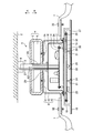
- FIG. 1 is a cross-sectional view of an essential part of a ceiling fan 1 according to a first embodiment of the present invention.
- FIG. 2 is an exploded perspective view of the ceiling fan 1 according to the first embodiment.
- the cross sections of some components of the ceiling fan 1 are hatched, and the hatching of the cross sections of the other components is omitted.
- the components shown in FIG. 1 include components not shown in FIG.
- the ceiling fan 1 is suspended from the ceiling 2 and installed.
- the ceiling fan 1 includes a motor 4 having a rotor 5 and a stator 6, a shaft 3 penetrating the center of the motor 4, and a plurality of blades 7.
- a hollow pipe material is used for the shaft 3.
- the upper end of the shaft 3 is fixed to a hanging portion 9 attached to the ceiling 2.
- the shaft 3 supports the entire ceiling fan 1.
- the motor 4 is supported by a shaft 3 penetrating the stator 6.
- the motor 4 is a so-called external rotation type motor in which a rotor 5 surrounding the stator 6 rotates.
- the rotor 5 of the motor 4 rotates about an axis AX.
- the axis AX is an axis that is the rotation center of the rotor 5 and is also the center line of the shaft 3.
- the ceiling fan 1 is installed with the axis AX aligned in the vertical direction. In the direction of the axis AX, the direction of the arrow A directed to the ceiling 2 represents a first direction which is upward.
- the direction of the arrow B opposite to the arrow A in the direction of the axis AX represents a second direction which is downward.
- the ceiling fan 1 includes a connecting part 8 that connects the rotor 5 and the plurality of blades 7.
- the connection part 8 is disposed below the motor 4.
- the connection part 8 is erected in the direction of the axis AX by the first part 11 fixed to the rotor 5, the second part 12 to which the plurality of blades 7 are fixed, and the first part 11 and the second part 12 and a third portion 13 connected to each other.
- the first portion 11 is a portion that forms the upper surface of the connection component 8.
- the second portion 12 is located on the side of the direction perpendicular to the direction of the axis AX, away from the axis AX, of the first portion 11. Further, the second portion 12 is located below the first portion 11.
- the second portion 12 is a portion that forms the lower surface of the connection component 8.
- the third portion 13 is a portion forming a cylindrical surface which is a side surface of the connection part 8.
- the first portion 11 and the third portion 13 constitute a box including a cylindrical surface and having an open lower side.
- the second portion 12 projects like a collar from the open portion of the box to the outside of the cylindrical surface.
- a metal material is used as the material of the connection part 8.
- the first portion 11 is a circular plate-like portion. At the center of the plane of the first portion 11, an opening 38 through which the shaft 3 passes is provided.
- the third portion 13 is a portion having a cylindrical shape parallel to the axis AX.
- the first portion 11 is connected to the upper end of the third portion 13.
- the second portion 12 is connected to the lower end of the third portion 13.
- the second portion 12 is a flat portion which is spread from the lower end of the third portion 13 in a direction away from the center of the cylindrical shape of the third portion 13.
- the plurality of blades 7 are arranged at equal intervals at the outer edge of the second portion 12. Two vanes 7 are shown in FIGS. 1 and 2.
- the number of blades 7 provided in the ceiling fan 1 may be more than two.
- the first portion 11 is fixed to the lower surface of the rotor 5 by a screw 31.
- Each blade 7 is fixed to the upper surface of the second portion 12 by a screw 32.
- the connection part 8 and the plurality of blades 7 rotate with the rotor 5 by the drive of the motor 4.
- the ceiling fan 1 includes a first circuit board 14 on which a circuit component responsible for supplying electric power to the motor 4 is mounted and a second circuit board 15 on which a circuit component responsible for controlling the operation of the ceiling fan 1 is mounted.
- the second circuit board 15 is mounted with a light emitting diode 21 which is a light emitting body, a light receiving element 22 which receives an infrared signal from a remote controller described later, and a buzzer 23 which generates a notification sound.
- the circuit components mounted on the first circuit board 14 and the circuit components mounted on the second circuit board 15 will be described later.
- the first circuit board 14 is housed in the housing case 16.
- the shape of the storage case 16 is similar to the shape obtained by reducing the shape of the connecting part 8.
- the connection part 8 and the storage case 16 are arranged at intervals. Thereby, the connection component 8 rotates without contacting the storage case 16.
- the lid 17 closes the storage case 16 from below.
- a metal material that is a material having fire resistance is used for the material of the storage case 16 and the material of the lid 17, a metal material that is a material having fire resistance is used.
- the first circuit board 14 is placed on the protrusion 35 of the lid 17 which is erected on the inner surface of the storage case 16, and is fixed to the protrusion 35 by the screw 34.
- the storage case 16 and the lid 17 are fixed by screws 33 to the upper surface of the storage case 18 described later.
- the first circuit board 14 is disposed in the storage case 16 in a space surrounded by the third portion 13.
- the first circuit board 14 may be attached to the inner surface of the storage case 16 in addition to
- an AC power supply line 27 which extends from the ceiling 2 to the inside of the storage case 16 through the inside of the shaft 3.
- a motor connection line 26 that passes from the first circuit board 14 to the inside of the shaft 3.
- a fitting portion 20 into which the lower end of the shaft 3 is fitted is provided on the upper surface of the storage case 16.
- the lower end of the shaft 3 is fitted into the fitting portion 20, and the storage case 16 is fixed to the shaft 3.
- the shaft 3 supports the storage case 16 and components fixed directly or indirectly to the storage case 16.
- the second circuit board 15 is housed in the housing case 18.
- the surface of the second circuit board 15 on which the light emitting diode 21, the light receiving element 22, the buzzer 23 and the circuit component are mounted is directed downward.
- the shape of the storage case 18 is a combination of the storage case 16 and the lid 17 in such a manner that the size in the vertical direction is shortened and the size in the horizontal direction is increased.
- a resin material is used as the material of the storage case 18.
- the second circuit board 15 is pressed from below onto a projection 37 that is erected downward from the upper inner surface of the storage case 18 and fixed to the projection 37 by a screw 36.
- the second circuit board 15 is disposed at a position other than the space enclosed by the third portion 13.
- the lower surface portion of the storage case 18 is provided with a window 24 for transmitting light from the light emitting diode 21 and a window 25 for transmitting infrared light from the remote controller.
- the windows 24 and 25 are embedded with a transparent material or a translucent material.
- the entire lower surface portion of the storage case 18 may be a plate of a transparent material or a translucent material.
- a design sheet 19 is attached to the lower surface of the storage case 18. On the surface of the design sheet 19 directed downward, a design by printing or the like is provided.
- the design sheet 19 covers the entire lower surface of the storage case 18.
- a window 24A for transmitting the light from the light emitting diode 21 is provided at a position directly below the light emitting diode 21 and the window 24 in the design sheet 19.
- the window 24A is a transparent or translucent portion of the designed surface.
- a window 25A for transmitting infrared light from the remote controller is provided at a position directly below the light receiving element 22 and the window 25 in the design sheet 19.
- An infrared transmitting material is printed on the window 25A.
- the design sheet 19 and the plurality of blades 7 are disposed at the same distance from the ceiling 2.
- the position of the design sheet 19 in the vertical direction is the same as the positions of the plurality of blades 7 in the vertical direction.
- FIG. 3 is a diagram showing a circuit configuration of the first circuit board 14 and the second circuit board 15 which the ceiling fan 1 according to the first embodiment has.
- the commercial alternating current power supply 41 and the motor 4 are connected to the first circuit board 14.
- a DC power generation circuit 51, a control DC power supply 52, a capacitor 53, a triac 54, a resistor 55, and a start capacitor 56 are mounted on the first circuit board 14.
- the DC power supply generation circuit 51, the control DC power supply 52, the capacitor 53, the triac 54, the resistor 55, and the startup capacitor 56 are circuit components responsible for supplying power from the commercial AC power supply 41 to the motor 4. .
- the capacitor 53, the triac 54 and the resistor 55 are connected in series between the commercial AC power supply 41 and the motor 4.
- the capacitor 53A, the triac 54A, and the resistor 55A are connected in series.
- the capacitor 53B, the triac 54B, and the resistor 55B are connected in series.
- the triac 54C and the resistor 55C are connected in series.
- the capacitors 53A and 53B are capacitors 53 having different capacities.
- the capacitor 53 refers to each of the capacitors 53A and 53B without distinction.
- the triac 54 refers to each of the triacs 54A, 54B, 54C without distinction.
- the resistor 55 refers to each of the resistors 55A, 55B, 55C without distinction.
- the voltage of the commercial AC power supply 41 is divided by the impedance of the motor 4 and the impedance of the capacitor 53 and applied to the motor 4.
- the voltage applied to the motor 4 is changed by switching between the state in which the capacitor 53A is connected to the motor 4, the state in which the capacitor 53B is connected to the motor 4, and the state in which the capacitors 53A and 53B are not connected to the motor 4.
- the air volume of the ceiling fan 1 is switched by changing the voltage applied to the motor 4 to change the rotational speed of the motor 4.
- the triac 54 which is a power semiconductor element is responsible for switching between a state in which the capacitor 53A is connected to the motor 4, a state in which the capacitor 53B is connected to the motor 4, and a state in which the capacitors 53A and 53B are not connected to the motor 4.
- the conduction of the triac 54A connects the circuit including the capacitor 53A to the motor 4.
- the conduction of the triac 54 B connects the circuit including the capacitor 53 B to the motor 4.
- the conduction of the triac 54C connects a circuit not including the capacitors 53A and 53B to the motor 4.
- the capacitance of the capacitor 53B is smaller than the capacitance of the capacitor 53A. As the capacitance of the capacitor 53 is smaller, the impedance of the capacitor 53 is larger.
- the TRIAC 54C conducts, the voltage of the commercial AC power supply 41 is applied to the motor 4, whereby the air volume of the ceiling fan 1 becomes the maximum air volume among the air volumes of the three stages.
- the TRIAC 54A conducts, the voltage of the commercial AC power supply 41 is reduced by the capacitor 53A and applied to the motor 4.
- the air volume of the ceiling fan 1 is one step smaller than the maximum air volume.
- the triac 54 B conducts, the voltage of the commercial AC power supply 41 is reduced by the capacitor 53 B and applied to the motor 4.
- the air volume of the ceiling fan 1 is the smallest of the three air volumes.
- the resistor 55 plays a role of suppressing inrush current when the air volume is switched. The inrush current is generated by the charge stored in the capacitors 53A and 53B.
- the startup capacitor 56 is connected between the commercial AC power supply 41 and the auxiliary winding 44 of the motor 4.
- the startup capacitor 56 may be provided in the motor 4 instead of the first circuit board 14.
- the DC power supply generation circuit 51 generates a voltage of the control DC power supply 52 of about several volts from the voltage of the commercial AC power supply 41 of 100V system or 200V system.
- a switching circuit capable of stabilizing the output voltage regardless of the fluctuation of the power supplied from the commercial AC power supply 41 and the fluctuation of the load power is generally used.
- the control DC power supply 52 supplies power to the control DC power supply 62 of the second circuit board 15 through the DC power supply wire 43.
- a sensor unit 63 including a light receiving element 22, a plurality of light emitting diodes 21, a buzzer 23, a microcomputer 61 as a processing circuit, and a control DC power supply 62 are mounted on the second circuit board 15. .
- the sensor unit 63, the plurality of light emitting diodes 21, the buzzer 23, and the microcomputer 61 operate with the power supplied from the control DC power supply 62.
- the microcomputer 61 is a circuit component responsible for controlling the operation of the ceiling fan 1.
- Three light emitting diodes 21 are provided on the second circuit board 15 shown in FIG.
- the number of light emitting diodes 21 provided on the second circuit board 15 may be less than three and may be more than three.
- the light emitting diode 21 either a shell type light emitting diode or a surface mount type light emitting diode may be used.
- the remote controller 40 transmits an infrared signal corresponding to the input operation.
- the sensor unit 63 receives an infrared signal from the remote controller 40 at the light receiving element 22.
- the sensor unit 63 sends a signal corresponding to the received infrared signal to the microcomputer 61.
- the microcomputer 61 detects a signal from the sensor unit 63, it sends control signals to the plurality of light emitting diodes 21, the buzzer 23 and the triac 54.
- the microcomputer 61 transmits a gate trigger signal to the gate terminal of the triac 54 through the signal wire 42 when switching the air volume.
- the triacs 54A, 54B, 54C switch between conduction and interruption in accordance with the gate trigger signal received from the microcomputer 61.
- the buzzer 23 receives from the microcomputer 61 a control signal indicating that the instruction by the input operation to the remote controller 40 has been received, the buzzer 23 generates an operation sound which is one of the notification sounds.
- the plurality of light emitting diodes 21 switch on and off according to the level of the air volume after switching.
- the ceiling fan 1 switches the light emitting diodes 21 to be lighted out of the plurality of light emitting diodes 21 to display an operation mode such as weak, medium or strong indicating the level of the air volume.
- a light emitter for illumination may be mounted on the second circuit board 15.
- the connector 57 mounted on the first circuit board 14 and the connector 64 mounted on the second circuit board 15 are connected by the signal wire 42 and the DC power supply wire 43. Since the current capacity of the signal wire 42 and the DC power supply wire 43 is small, thin wires are used for the signal wire 42 and the DC power supply wire 43.
- the signal wire 42 and the DC power supply wire 43 are put together and can be connected to the connectors 57 and 64.
- the signal wire 42 and the DC power supply wire 43 are passed through a flame retardant material such as a rubber bush.
- the blades 7 are fixed to the second portion 12 below the first portion 11 fixed to the rotor 5, the blades 7 are disposed at a position below the motor 4. It is done.
- the blade 7 By the blade 7 being extended from the second portion 12 positioned on the side away from the axis AX with respect to the first portion 11, the third portion below the first portion 11 of the connection component 8 A space enclosed by 13 is provided.
- the ceiling fan 1 can arrange the first circuit board 14 in such a space.
- the ceiling fan 1 moves downward from the blade 7 as compared to the case where the circuit component responsible for supplying power to the motor 4 and the circuit component responsible for controlling the operation of the ceiling fan 1 are disposed in the storage case below the blade 7. Can be reduced.
- the arrangement of the blades 7 below the motor 4 makes it easy to secure the distance between the ceiling 2 and the blades 7.
- the space between the ceiling 2 and the blades 7 is secured, so that the obstruction of the air flow at the ceiling 2 can be reduced, and the reduction of the air volume can be suppressed.
- the circuit component responsible for supplying electric power to the motor 4 and the circuit component responsible for controlling the operation of the ceiling fan 1 are divided into the first circuit board 14 and the second circuit board 15 and arranged There is.
- the first circuit board 14 on which the circuit component requiring a large space in the height direction from the mounting surface, such as the capacitor 53 and the power semiconductor element, is mounted is accommodated in the connection component 8.
- the ceiling fan 1 can arrange the design sheet 19 and the plurality of blades 7 on the horizontal plane at the same distance from the ceiling 2 because the storage case 18 can be made thin.
- the ceiling fan 1 can improve the design by arranging the design sheet 19 at the same height position as the plurality of blades 7 as a configuration that does not include downward protrusion from the height of the blades 7.
- the first circuit board 14 and the second circuit board 15 are divided into the storage case 16 in the space enclosed by the third portion 13 and the storage case 18 below the connection component 8. It is stored.
- the circuit components mounted on the second circuit board 15 are less susceptible to the heat generated from the power semiconductor elements of the first circuit board 14 when the motor 4 is driven.
- the ceiling fan 1 can reduce the malfunction of the circuit components such as the microcomputer 61, the sensor unit 63, and the light emitting diode 21 due to the influence of heat, and can prolong the life.
- the ceiling fan 1 can seal a circuit component responsible for supplying power from the commercial AC power supply 41 to the motor 4 with a storage case 16 made of a fireproof material and a lid 17.
- the ceiling fan 1 keeps the radiation noise emitted from the DC power supply generation circuit 51 in a sealed space constituted by the storage case 16 and the lid 17 made of metal material, and leaks high frequency noise to the periphery of the ceiling fan 1. It can be reduced.
- the light emitting diode 21, the light receiving element 22 and the buzzer 23, which are required to be disposed downward, are mounted on the mounting surface directed downward.
- the microcomputer 61 By mounting the microcomputer 61 on the mounting surface, the microcomputer 61 can be connected to the light emitting diode 21, the light receiving element 22 and the buzzer 23 by an easy wiring operation.
- the time required for the wiring operation can be reduced.
- the light emitting diode 21 can be mounted on the second circuit board 15 with a lead length suitable for automatic mounting. Compared with the case where mounting of the light emitting diode 21 is required manually, the time required for the mounting operation and the time required for the correction operation after mounting can be reduced.
- a surface mount type light emitting diode may be used as the light emitting diode 21 because a circuit component that requires a small space in the height direction from the mounting surface is mounted on the second circuit board 15. When a surface-mounted light emitting diode is used as the light emitting diode 21, the position adjustment operation of the light emitting diode 21 becomes unnecessary.
- the light receiving element 22 and the buzzer 23 are disposed in the storage case 18 located at the lower part of the ceiling fan 1.
- the ceiling fan 1 can stably receive an infrared signal transmitted from a wide range of the room by arranging the light receiving element 22 under the ceiling fan 1.
- the buzzer 23 is disposed at the lower part of the ceiling fan 1, so that the notification sound can be transmitted to a wide range of occupants in the room.
- the ceiling fan 1 has the ceiling 2 and the ceiling fan 2 by fixing the blades 7 to the second site 12 located on the second direction side of the first site 11 in the connecting component 8. There is an effect that projection from the ceiling 2 can be suppressed while securing a distance from the blade 7.
- the configuration shown in the above embodiment shows an example of the contents of the present invention, and can be combined with another known technique, and one of the configurations is possible within the scope of the present invention. Parts can be omitted or changed.
Landscapes
- Engineering & Computer Science (AREA)
- Mechanical Engineering (AREA)
- General Engineering & Computer Science (AREA)
- Structures Of Non-Positive Displacement Pumps (AREA)
Abstract
天井扇風機(1)は、羽根(7)と、軸(AX)を中心に回転可能な回転子(5)を有するモータ(4)と、モータ(4)よりも、軸(AX)の方向のうち天井(2)へ向かう向きである第1の向きとは逆の第2の向きの側に配置されており、回転子(5)と羽根(7)とを連結する連結部品(8)とを備える。連結部品(8)は、回転子(5)に固定されている第1部位(11)と、第1部位(11)よりも、軸(AX)の方向に垂直な方向のうち軸(AX)から離れる向きの側に位置しており、羽根(7)が固定されている第2部位(12)と、を有する。第2部位(12)は、第1部位(11)よりも第2の向きの側に位置している。
Description
本発明は、天井から吊り下げられて設置される天井扇風機に関する。
天井扇風機は、室内の空調効率の向上のため、あるいは室内の装飾として、室内の天井から吊り下げられて設置される。特許文献1には、シャフトが貫かれている固定子を囲う回転子を有するいわゆる外転型のモータと、モータの回転子に固定されている羽根とを備える天井扇風機が開示されている。特許文献1の天井扇風機では、モータを制御する制御手段が収納された収納ケースがモータの下方側に設けられている。
特許文献1の天井扇風機は、鉛直方向においてモータと同じ高さ位置に羽根が配置されていることで、モータの下方側に設けられている収納ケースの寸法の分、羽根の高さよりも下方へ突出している部分が生じることとなる。天井扇風機は、下方への突出が大きくなることで、室内の居住者に圧迫感を感じさせることがあり得る。天井扇風機の下方への突出が大きくなることで、天井扇風機の意匠性を悪化させることがあり得る。天井扇風機の下方への突出を抑えるために、モータと収納ケースとが天井に近づけられると、羽根と天井との間隔が短くなる。羽根と天井との間隔が短いほど、羽根の回転による気流の発生が天井面により阻害されることとなるため、天井扇風機の運転によって得られる風量が少なくなる。
本発明は、上記に鑑みてなされたものであって、天井と羽根との間隔を確保しつつ天井からの突出を抑えることができる天井扇風機を得ることを目的とする。
上述した課題を解決し、目的を達成するために、本発明にかかる天井扇風機は、天井から吊り下げられて設置される。本発明にかかる天井扇風機は、羽根と、軸を中心に回転可能な回転子を有するモータと、モータよりも、軸の方向のうち天井へ向かう向きである第1の向きとは逆の第2の向きの側に配置されており、回転子と羽根とを連結する連結部品とを備える。連結部品は、回転子に固定されている第1部位と、第1部位よりも、軸の方向に垂直な方向のうち軸から離れる向きの側に位置しており、羽根が固定されている第2部位と、を有する。第2部位は、第1部位よりも第2の向きの側に位置している。
本発明にかかる天井扇風機は、天井と羽根との間隔を確保しつつ天井からの突出を抑えることができるという効果を奏する。
以下に、本発明の実施の形態にかかる天井扇風機を図面に基づいて詳細に説明する。なお、この実施の形態によりこの発明が限定されるものではない。
実施の形態1.
図1は、本発明の実施の形態1にかかる天井扇風機1の要部断面図である。図2は、実施の形態1にかかる天井扇風機1の分解斜視図である。図1では、天井扇風機1のうち一部の構成部品の断面にはハッチングを付し、その他の構成部品の断面のハッチングを省略している。図1に示している構成部品には、図2において図示が省略されている構成部品が含まれている。
図1は、本発明の実施の形態1にかかる天井扇風機1の要部断面図である。図2は、実施の形態1にかかる天井扇風機1の分解斜視図である。図1では、天井扇風機1のうち一部の構成部品の断面にはハッチングを付し、その他の構成部品の断面のハッチングを省略している。図1に示している構成部品には、図2において図示が省略されている構成部品が含まれている。
天井扇風機1は、天井2から吊り下げられて設置される。天井扇風機1は、回転子5と固定子6とを有するモータ4と、モータ4の中心を貫くシャフト3と、複数の羽根7とを備える。シャフト3には、中空のパイプ材が使用されている。シャフト3の上端は、天井2に取り付けられた吊下部9に固定されている。シャフト3は、天井扇風機1の全体を支持する。
モータ4は、固定子6を貫くシャフト3によって支持されている。モータ4は、固定子6を囲う回転子5が回転するいわゆる外転型のモータである。モータ4の回転子5は、軸AXを中心に回転する。軸AXは、回転子5の回転中心であって、シャフト3の中心線でもある軸とする。天井扇風機1は、軸AXを鉛直方向に合わせて設置される。なお、軸AXの方向のうち天井2へ向かう矢印Aの向きは、上向きである第1の向きを表している。軸AXの方向のうち矢印Aとは逆の矢印Bの向きは、下向きである第2の向きを表す。
天井扇風機1は、回転子5と複数の羽根7とを連結する連結部品8を備える。連結部品8は、モータ4よりも下方に配置されている。連結部品8は、回転子5に固定されている第1部位11と、複数の羽根7が固定されている第2部位12と、軸AXの方向に立てられて第1部位11と第2部位12とをつないでいる第3部位13とを有する。第1部位11は、連結部品8の上面をなす部位である。第2部位12は、第1部位11よりも、軸AXの方向に垂直な方向のうち軸AXから離れる向きの側に位置している。また、第2部位12は、第1部位11よりも下方に位置している。第2部位12は、連結部品8の下面をなす部位である。第3部位13は、連結部品8の側面である円筒面をなす部位である。第1部位11と第3部位13とは、円筒面を含むとともに下方が開放された箱体を構成している。かかる箱体の開放部分から円筒面の外側へ、第2部位12がつば状に突出している。連結部品8の材料には、金属材料が使用されている。
第1部位11は、円形をなす平板状の部位である。第1部位11の平面の中心には、シャフト3が通される開口38が設けられている。第3部位13は、軸AXに平行な円筒形状をなす部位である。第1部位11は、第3部位13の上端に繋げられている。第2部位12は、第3部位13の下端に繋げられている。第2部位12は、第3部位13の下端から、第3部位13の円筒形状の中心から離れる向きへ広げられた平板状の部位である。複数の羽根7は、第2部位12の外縁において等間隔をなして配置されている。図1および図2には2つの羽根7を示している。天井扇風機1に設けられる羽根7の数は、2つより多くても良い。
第1部位11は、ネジ31により回転子5の下面に固定されている。各羽根7は、ネジ32により第2部位12の上面に固定されている。連結部品8および複数の羽根7は、モータ4の駆動により、回転子5とともに回転する。
天井扇風機1は、モータ4への電力供給を担う回路部品が実装された第1の回路基板14と、天井扇風機1の動作の制御を担う回路部品が実装された第2の回路基板15とを備える。第2の回路基板15には、発光体である発光ダイオード21と、後述するリモートコントローラからの赤外線信号を受ける受光素子22と、報知音を発生するブザー23とが搭載されている。第1の回路基板14に実装されている回路部品と第2の回路基板15に実装されている回路部品とについては後述する。
第1の回路基板14は、収納ケース16に収納されている。収納ケース16の形状は、連結部品8の形状を縮小させた形状に近い形状をなしている。連結部品8と収納ケース16とは、互いに間隔をなして配置されている。これにより、連結部品8は、収納ケース16へ接触せずに回転する。蓋17は、収納ケース16を下方から塞ぐ。収納ケース16の材料と蓋17の材料とには、耐火性を備えた材料である金属材料が使用されている。第1の回路基板14は、蓋17のうち収納ケース16の内部側の面に立てられた突起35の上に載せられて、ネジ34により突起35に固定されている。収納ケース16と蓋17とは、ネジ33により、後述する収納ケース18の上面に固定されている。第1の回路基板14は、第3部位13により囲われた空間にて、収納ケース16に収納された状態で配置されている。なお、第1の回路基板14は、突起35の上に載せられる以外に、収納ケース16の内面に取り付けられても良い。
第1の回路基板14には、天井2からシャフト3の内部を通されて収納ケース16の内部にまで延ばされている交流電源線27が接続されている。モータ4には、第1の回路基板14からシャフト3の内部を通されたモータ接続線26が接続されている。
収納ケース16の上面には、シャフト3の下端が嵌め込まれる嵌め込み部20が設けられている。シャフト3の下端が嵌め込み部20へ嵌め込まれて、収納ケース16はシャフト3に固定されている。収納ケース16がシャフト3に固定されることにより、シャフト3は、収納ケース16と、収納ケース16に直接あるいは間接的に固定されている構成部品とを支持している。
第2の回路基板15は、収納ケース18に収納されている。第2の回路基板15のうち、発光ダイオード21と、受光素子22と、ブザー23と、回路部品とが実装されている面は、下方へ向けられている。収納ケース18の形状は、上記の収納ケース16と蓋17とを合わせた形状を、鉛直方向の寸法を短くするとともに水平方向の寸法を長くするように変形させたような形状をなしている。収納ケース18の材料には、樹脂材料が使用されている。第2の回路基板15は、収納ケース18の上部内面から下方へ立てられた突起37に下方から当てられて、ネジ36により突起37に固定されている。このように、第2の回路基板15は、第1の回路基板14とは異なり、第3部位13により囲われた空間以外の位置に配置されている。
収納ケース18の下面部には、発光ダイオード21からの光を透過させる窓24と、リモートコントローラからの赤外線を透過させる窓25とが設けられている。窓24,25には、透明材料または半透明材料が埋め込まれている。なお、収納ケース18の下面部の全体が、透明材料または半透明材料の板であっても良い。収納ケース18の下面部には、意匠シート19が貼付されている。意匠シート19のうち下方へ向けられる面には、印刷等による意匠が施されている。意匠シート19は、収納ケース18の下面部全体を覆う。意匠シート19のうち発光ダイオード21および窓24の直下の位置には、発光ダイオード21からの光を透過させる窓24Aが設けられている。窓24Aは、意匠が施された面のうち透明または半透明とされた部分である。意匠シート19のうち受光素子22および窓25の直下の位置には、リモートコントローラからの赤外線を透過させる窓25Aが設けられている。窓25Aには、赤外線透過材料が印刷されている。
意匠シート19と複数の羽根7とは、天井2から同じ距離の位置に配置される。言い換えると、鉛直方向における意匠シート19の位置と、鉛直方向における複数の羽根7の位置とが同じとされている。
次に、第1の回路基板14に実装されている回路部品と第2の回路基板15に実装されている回路部品とについて説明する。図3は、実施の形態1にかかる天井扇風機1が有する第1の回路基板14および第2の回路基板15の回路構成を示す図である。
第1の回路基板14には、商用交流電源41とモータ4とが接続されている。第1の回路基板14には、直流電源生成回路51と、制御用直流電源52と、コンデンサ53と、トライアック54と、抵抗55と、起動用コンデンサ56とが実装されている。直流電源生成回路51と、制御用直流電源52と、コンデンサ53と、トライアック54と、抵抗55と、起動用コンデンサ56とは、商用交流電源41からモータ4への電力供給を担う回路部品である。
コンデンサ53と、トライアック54と、抵抗55とは、商用交流電源41とモータ4との間に直列に接続されている。コンデンサ53Aと、トライアック54Aと、抵抗55Aとは、直列に接続されている。コンデンサ53Bと、トライアック54Bと、抵抗55Bとは、直列に接続されている。トライアック54Cと、抵抗55Cとは、直列に接続されている。コンデンサ53Aとコンデンサ53Bとは、互いに容量が異なるコンデンサ53である。コンデンサ53は、コンデンサ53A,53Bの各々を区別せずに称したものとする。トライアック54は、トライアック54A,54B,54Cの各々を区別せずに称したものとする。抵抗55は、抵抗55A,55B,55Cの各々を区別せずに称したものとする。
商用交流電源41の電圧は、モータ4のインピーダンスとコンデンサ53のインピーダンスとで分圧されてモータ4に印加される。モータ4にコンデンサ53Aが接続された状態と、モータ4にコンデンサ53Bが接続された状態と、モータ4にコンデンサ53A,53Bが接続されない状態との切り換えにより、モータ4に印加される電圧が変化する。天井扇風機1の風量は、モータ4に印加される電圧を変化させてモータ4の回転数を変化させることにより切り換えられる。
パワー半導体素子であるトライアック54は、モータ4にコンデンサ53Aが接続された状態と、モータ4にコンデンサ53Bが接続された状態と、モータ4にコンデンサ53A,53Bが接続されない状態との切り換えを担う。トライアック54Aの導通により、コンデンサ53Aを含む回路がモータ4に接続される。トライアック54Bの導通により、コンデンサ53Bを含む回路がモータ4に接続される。トライアック54Cの導通により、コンデンサ53A,53Bを含まない回路がモータ4に接続される。
以下の説明では、コンデンサ53Bの容量は、コンデンサ53Aの容量より小さいとする。コンデンサ53の容量が小さいほど、コンデンサ53のインピーダンスは大きくなる。トライアック54Cが導通した場合、商用交流電源41の電圧がモータ4に印加されることで、天井扇風機1の風量は、3段階の風量のうち最大の風量となる。トライアック54Aが導通した場合、商用交流電源41の電圧は、コンデンサ53Aにて小さくされて、モータ4に印加される。天井扇風機1の風量は、最大の風量より1段階小さい風量となる。トライアック54Bが導通した場合、商用交流電源41の電圧は、コンデンサ53Bにて小さくされて、モータ4に印加される。天井扇風機1の風量は、3段階の風量のうち最小の風量となる。抵抗55は、風量が切り換えられる際における突入電流を抑制する役割を果たす。突入電流は、コンデンサ53A,53Bに蓄積されている電荷により生じる。
起動用コンデンサ56は、商用交流電源41とモータ4の補助巻き線44との間に接続されている。起動用コンデンサ56は、第1の回路基板14ではなくモータ4の中に設けられても良い。
直流電源生成回路51は、100V系または200V系の商用交流電源41の電圧から、数V程度の制御用直流電源52の電圧を生成する。直流電源生成回路51には、商用交流電源41から供給される電力の変動と負荷電力の変動とに関わらず出力電圧の安定化を図り得るスイッチング回路が一般的に用いられる。制御用直流電源52は、直流電源用電線43により第2の回路基板15の制御用直流電源62へ電力を供給する。
第2の回路基板15には、受光素子22を含むセンサ部63と、複数の発光ダイオード21と、ブザー23と、処理回路であるマイクロコンピュータ61と、制御用直流電源62とが実装されている。センサ部63と、複数の発光ダイオード21と、ブザー23と、マイクロコンピュータ61とは、制御用直流電源62から供給される電力により動作する。マイクロコンピュータ61は、天井扇風機1の動作の制御を担う回路部品である。図3に示す第2の回路基板15には、3つの発光ダイオード21が設けられている。第2の回路基板15に設けられる発光ダイオード21は、3つより少なくても良く、3つより多くても良い。発光ダイオード21には、砲弾型の発光ダイオードと面実装型の発光ダイオードとのどちらが用いられても良い。
リモートコントローラ40は、入力操作に応じた赤外線信号を送信する。センサ部63は、リモートコントローラ40からの赤外線信号を受光素子22にて受信する。センサ部63は、受信された赤外線信号に応じた信号をマイクロコンピュータ61へ送る。マイクロコンピュータ61は、センサ部63からの信号を検出すると、複数の発光ダイオード21とブザー23とトライアック54とへ制御信号を送る。
マイクロコンピュータ61は、風量の切り換えの際、信号用電線42を通じて、トライアック54のゲート端子へゲートトリガ信号を送信する。トライアック54A,54B,54Cは、マイクロコンピュータ61から受信したゲートトリガ信号にしたがって導通と遮断とを切り換える。ブザー23は、リモートコントローラ40への入力操作による指示を受け付けたことを示す制御信号をマイクロコンピュータ61から受信した場合、報知音の1つである操作音を発生する。複数の発光ダイオード21は、風量の切り換えについての制御信号をマイクロコンピュータ61から受信した場合、切り換え後の風量のレベルにしたがって点灯と消灯とを切り換える。天井扇風機1は、複数の発光ダイオード21のうち点灯する発光ダイオード21を切り換えることにより、風量のレベルを表す弱、中、強といった運転モードを表示する。なお、第2の回路基板15には、表示のための発光体のほかに、照明のための発光体が搭載されていても良い。
第1の回路基板14に搭載されているコネクタ57と第2の回路基板15に搭載されているコネクタ64とは、信号用電線42と直流電源用電線43とにより接続されている。信号用電線42と直流電源用電線43との電流容量は小さいため、信号用電線42と直流電源用電線43とには細い電線が使用される。信号用電線42と直流電源用電線43とは、纏められてコネクタ57,64に接続可能である。信号用電線42と直流電源用電線43とは、ゴムブッシュといった難燃性の材料に通されている。
実施の形態1によると、回転子5に固定されている第1部位11よりも下方の第2部位12に羽根7が固定されていることで、モータ4よりも下方の位置に羽根7が配置されている。第1部位11よりも軸AXから離れる向きの側に位置している第2部位12から羽根7が延ばされていることで、連結部品8のうち第1部位11の下方に、第3部位13により囲われた空間が設けられている。天井扇風機1は、かかる空間に第1の回路基板14を配置できる。天井扇風機1は、モータ4への電力供給を担う回路部品と天井扇風機1の動作の制御を担う回路部品とが羽根7より下方の収納ケースに配置される場合に比べて、羽根7から下方への突出を少なくすることができる。
モータ4よりも下方の位置に羽根7が配置されていることで、天井2と羽根7との間隔の確保が容易となる。天井扇風機1は、天井2と羽根7との間隔が確保されることで、天井2での気流の阻害を低減でき、風量の低下を抑えることができる。
天井扇風機1では、モータ4への電力供給を担う回路部品と天井扇風機1の動作の制御を担う回路部品とが第1の回路基板14と第2の回路基板15とに分けられて配置されている。コンデンサ53およびパワー半導体素子といった、実装面からの高さ方向における大きなスペースを要する回路部品が搭載された第1の回路基板14は、連結部品8内に収納される。連結部品8の下方に配置される第2の回路基板15には、実装面からの高さ方向におけるスペースが小さくても済む回路部品が搭載されている。天井扇風機1は、連結部品8より下方の収納ケース18を薄型にできることで、下方への突出を少なくすることができる。
また、天井扇風機1は、収納ケース18を薄型にできることで、意匠シート19と複数の羽根7とを、天井2から同じ距離の水平面上に配置できる。天井扇風機1は、羽根7の高さからの下方への突出を含まない構成として、複数の羽根7と同じ高さ位置に意匠シート19を配置できることで、意匠性の向上を図ることができる。
天井扇風機1では、第1の回路基板14と第2の回路基板15とが、第3部位13により囲われた空間内の収納ケース16と連結部品8より下方の収納ケース18とに分けられて収納される。第2の回路基板15に搭載された回路部品は、モータ4の駆動時に第1の回路基板14のパワー半導体素子から発せられる熱の影響を受けにくくなる。これにより、天井扇風機1は、マイクロコンピュータ61、センサ部63および発光ダイオード21といった回路部品について、熱の影響による動作不良を低減でき、かつ長寿命化を図ることができる。天井扇風機1は、商用交流電源41からモータ4への電力供給を担う回路部品を、耐火性を備えた材料からなる収納ケース16と蓋17とにより密閉できる。天井扇風機1は、直流電源生成回路51から発せられる放射性ノイズを、金属材料からなる収納ケース16と蓋17とにより構成される密閉空間にとどめて、天井扇風機1の周囲への高周波ノイズの漏れを低減できる。
第2の回路基板15では、下方へ向けての配置が求められる発光ダイオード21と受光素子22とブザー23とが、下方へ向けられた実装面に搭載される。かかる実装面にマイクロコンピュータ61が実装されることで、容易な配線作業により、マイクロコンピュータ61と、発光ダイオード21、受光素子22およびブザー23とが接続可能である。マイクロコンピュータ61、発光ダイオード21、受光素子22およびブザー23が収納ケース18の中と外とに分けられて配置される場合と比較して、配線作業に要する手間を低減できる。
発光ダイオード21に砲弾型の発光ダイオードが用いられる場合、実装面からの高さの調整が不要となり自動実装が可能となる。第2の回路基板15には、自動実装に適したリード長にて発光ダイオード21を実装できる。手作業による発光ダイオード21の実装を要する場合と比較して、実装作業に要する手間と、実装後の修正作業に要する手間とを低減できる。第2の回路基板15には、実装面からの高さ方向におけるスペースが小さくても済む回路部品が搭載されるため、発光ダイオード21には面実装型の発光ダイオードが用いられても良い。発光ダイオード21に面実装型の発光ダイオードが用いられる場合、発光ダイオード21の位置調整作業が不要となる。
受光素子22とブザー23とは、天井扇風機1のうち下部に位置する収納ケース18に配置される。天井扇風機1は、天井扇風機1の下部に受光素子22が配置されることで、室内の広範囲から送信された赤外線信号を安定して受信できる。天井扇風機1は、天井扇風機1の下部にブザー23が配置されることで、室内の広範囲の居住者に報知音を伝えることができる。
実施の形態1によると、天井扇風機1は、連結部品8のうち第1部位11よりも第2の向きの側に位置する第2部位12に羽根7が固定されていることで、天井2と羽根7との間隔を確保しつつ天井2からの突出を抑えることができるという効果を奏する。
以上の実施の形態に示した構成は、本発明の内容の一例を示すものであり、別の公知の技術と組み合わせることも可能であるし、本発明の要旨を逸脱しない範囲で、構成の一部を省略、変更することも可能である。
1 天井扇風機、2 天井、3 シャフト、4 モータ、5 回転子、6 固定子、7 羽根、8 連結部品、9 吊下部、11 第1部位、12 第2部位、13 第3部位、14 第1の回路基板、15 第2の回路基板、16,18 収納ケース、17 蓋、19 意匠シート、20 嵌め込み部、21 発光ダイオード、22 受光素子、23 ブザー、24,24A,25,25A 窓、26 モータ接続線、27 交流電源線、31,32,33,34,36 ネジ、35,37 突起、38 開口、40 リモートコントローラ、41 商用交流電源、42 信号用電線、43 直流電源用電線、44 補助巻き線、51 直流電源生成回路、52,62 制御用直流電源、53,53A,53B コンデンサ、54,54A,54B,54C トライアック、55,55A,55B,55C 抵抗、56 起動用コンデンサ、57,64 コネクタ、61 マイクロコンピュータ、63 センサ部、AX 軸。
Claims (8)
- 天井から吊り下げられて設置される天井扇風機であって、
羽根と、
軸を中心に回転可能な回転子を有するモータと、
前記モータよりも、前記軸の方向のうち前記天井へ向かう向きである第1の向きとは逆の第2の向きの側に配置されており、前記回転子と前記羽根とを連結する連結部品と、
を備え、
前記連結部品は、前記回転子に固定されている第1部位と、前記第1部位よりも、前記軸の方向に垂直な方向のうち前記軸から離れる向きの側に位置しており、前記羽根が固定されている第2部位と、を有し、
前記第2部位は、前記第1部位よりも前記第2の向きの側に位置していることを特徴とする天井扇風機。 - 前記モータへの電力供給を担う回路部品が実装された第1の回路基板を備え、
前記連結部品は、前記第1部位と前記第2部位との間において前記軸の方向に立てられている第3部位を有し、
前記第1の回路基板は、前記第3部位により囲われた空間に配置されていることを特徴とする請求項1に記載の天井扇風機。 - 前記第3部位により囲われた空間において前記第1の回路基板を収納する収納ケースを備えることを特徴とする請求項2に記載の天井扇風機。
- 前記天井扇風機の動作の制御を担う回路部品が実装された第2の回路基板を備え、
前記第2の回路基板は、前記連結部品よりも前記第2の向きの側に配置されていることを特徴とする請求項2または3に記載の天井扇風機。 - 前記第2の回路基板には、発光体が実装されていることを特徴とする請求項4に記載の天井扇風機。
- 前記第2の回路基板には、赤外線信号を受ける受光素子が実装されていることを特徴とする請求項4に記載の天井扇風機。
- 前記第2の回路基板には、報知音を発生するブザーが実装されていることを特徴とする請求項4に記載の天井扇風機。
- 前記第2の向きへ向けられ、意匠が施された意匠シートを備え、
前記意匠シートと前記羽根とは、前記天井から同じ距離の位置に配置されることを特徴とする請求項1から7のいずれか1つに記載の天井扇風機。
Priority Applications (3)
| Application Number | Priority Date | Filing Date | Title |
|---|---|---|---|
| PCT/JP2018/000417 WO2019138482A1 (ja) | 2018-01-11 | 2018-01-11 | 天井扇風機 |
| JP2019565120A JP6854927B2 (ja) | 2018-01-11 | 2018-01-11 | 天井扇風機 |
| MYPI2020003486A MY188652A (en) | 2018-01-11 | 2018-01-11 | Ceiling fan |
Applications Claiming Priority (1)
| Application Number | Priority Date | Filing Date | Title |
|---|---|---|---|
| PCT/JP2018/000417 WO2019138482A1 (ja) | 2018-01-11 | 2018-01-11 | 天井扇風機 |
Publications (1)
| Publication Number | Publication Date |
|---|---|
| WO2019138482A1 true WO2019138482A1 (ja) | 2019-07-18 |
Family
ID=67218228
Family Applications (1)
| Application Number | Title | Priority Date | Filing Date |
|---|---|---|---|
| PCT/JP2018/000417 Ceased WO2019138482A1 (ja) | 2018-01-11 | 2018-01-11 | 天井扇風機 |
Country Status (3)
| Country | Link |
|---|---|
| JP (1) | JP6854927B2 (ja) |
| MY (1) | MY188652A (ja) |
| WO (1) | WO2019138482A1 (ja) |
Citations (2)
| Publication number | Priority date | Publication date | Assignee | Title |
|---|---|---|---|---|
| JP2006219998A (ja) * | 2005-02-08 | 2006-08-24 | Matsushita Electric Ind Co Ltd | シーリングファン |
| JP2011157868A (ja) * | 2010-02-01 | 2011-08-18 | Panasonic Corp | シーリングファン |
-
2018
- 2018-01-11 WO PCT/JP2018/000417 patent/WO2019138482A1/ja not_active Ceased
- 2018-01-11 JP JP2019565120A patent/JP6854927B2/ja active Active
- 2018-01-11 MY MYPI2020003486A patent/MY188652A/en unknown
Patent Citations (2)
| Publication number | Priority date | Publication date | Assignee | Title |
|---|---|---|---|---|
| JP2006219998A (ja) * | 2005-02-08 | 2006-08-24 | Matsushita Electric Ind Co Ltd | シーリングファン |
| JP2011157868A (ja) * | 2010-02-01 | 2011-08-18 | Panasonic Corp | シーリングファン |
Also Published As
| Publication number | Publication date |
|---|---|
| MY188652A (en) | 2021-12-22 |
| JP6854927B2 (ja) | 2021-04-07 |
| JPWO2019138482A1 (ja) | 2020-04-23 |
Similar Documents
| Publication | Publication Date | Title |
|---|---|---|
| AU2011295983B2 (en) | Ventilation unit calibration apparatus, system and method | |
| US5253804A (en) | Temperature and humidity sensitive high efficiency exhaust ventilator apparatus | |
| US5232152A (en) | Range hood fan with atmospheric humidity sensor | |
| US11053955B2 (en) | Ceiling fan hanger bracket and receiver | |
| US9194603B2 (en) | Heating and ventilating fan | |
| US20060147310A1 (en) | Ceiling fan motor with stationary shaft | |
| WO2019138482A1 (ja) | 天井扇風機 | |
| CN111742182A (zh) | 空调机的室内机以及室内系统 | |
| JPS6352239B2 (ja) | ||
| CN108119379B (zh) | 送风装置 | |
| JP5509156B2 (ja) | ポンプ装置 | |
| JP2017066987A (ja) | 送風装置 | |
| JP2018003771A (ja) | 送風装置 | |
| JP2017198106A (ja) | 送風装置および送風装置システム | |
| JP6640045B2 (ja) | 壁掛型暖房機 | |
| JP7341046B2 (ja) | インバータ一体型モータ | |
| JP2017219241A (ja) | 可変風量装置 | |
| US12359678B1 (en) | Ceiling fan | |
| JP2012149546A (ja) | 送風装置およびそれを搭載した電気機器 | |
| US11572884B2 (en) | Direct current brushless fan and drive apparatus | |
| JP2020105959A (ja) | 天井扇風機 | |
| CN211874814U (zh) | 换气扇壳体结构 | |
| JPH02143045A (ja) | 空気調和機 | |
| KR20250120859A (ko) | 댐퍼 구동용 회로장치 및 이를 포함하는 욕실용 댐퍼 | |
| JP2007325425A (ja) | ブラシレスdcモータを搭載した換気送風装置 |
Legal Events
| Date | Code | Title | Description |
|---|---|---|---|
| 121 | Ep: the epo has been informed by wipo that ep was designated in this application |
Ref document number: 18900053 Country of ref document: EP Kind code of ref document: A1 |
|
| ENP | Entry into the national phase |
Ref document number: 2019565120 Country of ref document: JP Kind code of ref document: A |
|
| NENP | Non-entry into the national phase |
Ref country code: DE |
|
| 122 | Ep: pct application non-entry in european phase |
Ref document number: 18900053 Country of ref document: EP Kind code of ref document: A1 |