WO2019131087A1 - 太陽エネルギー利用器 - Google Patents
太陽エネルギー利用器 Download PDFInfo
- Publication number
- WO2019131087A1 WO2019131087A1 PCT/JP2018/045322 JP2018045322W WO2019131087A1 WO 2019131087 A1 WO2019131087 A1 WO 2019131087A1 JP 2018045322 W JP2018045322 W JP 2018045322W WO 2019131087 A1 WO2019131087 A1 WO 2019131087A1
- Authority
- WO
- WIPO (PCT)
- Prior art keywords
- prism
- angle
- solar energy
- triangular prism
- refractive index
- Prior art date
Links
- 230000003287 optical effect Effects 0.000 claims abstract description 32
- 239000000463 material Substances 0.000 claims description 37
- 230000007246 mechanism Effects 0.000 claims description 10
- 239000011521 glass Substances 0.000 abstract description 22
- 239000007788 liquid Substances 0.000 description 12
- 239000011148 porous material Substances 0.000 description 9
- XLYOFNOQVPJJNP-UHFFFAOYSA-N water Substances O XLYOFNOQVPJJNP-UHFFFAOYSA-N 0.000 description 8
- 238000010521 absorption reaction Methods 0.000 description 7
- YCKRFDGAMUMZLT-UHFFFAOYSA-N Fluorine atom Chemical compound [F] YCKRFDGAMUMZLT-UHFFFAOYSA-N 0.000 description 6
- 229910052731 fluorine Inorganic materials 0.000 description 6
- 239000011737 fluorine Substances 0.000 description 6
- 230000000694 effects Effects 0.000 description 5
- 238000007789 sealing Methods 0.000 description 5
- 238000000034 method Methods 0.000 description 4
- 239000011347 resin Substances 0.000 description 4
- 229920005989 resin Polymers 0.000 description 4
- 239000007787 solid Substances 0.000 description 4
- FAPWRFPIFSIZLT-UHFFFAOYSA-M Sodium chloride Chemical compound [Na+].[Cl-] FAPWRFPIFSIZLT-UHFFFAOYSA-M 0.000 description 3
- NIXOWILDQLNWCW-UHFFFAOYSA-N acrylic acid group Chemical group C(C=C)(=O)O NIXOWILDQLNWCW-UHFFFAOYSA-N 0.000 description 3
- 230000005540 biological transmission Effects 0.000 description 3
- 239000005388 borosilicate glass Substances 0.000 description 3
- 239000007789 gas Substances 0.000 description 3
- 238000009434 installation Methods 0.000 description 3
- 229920000515 polycarbonate Polymers 0.000 description 3
- 239000004417 polycarbonate Substances 0.000 description 3
- 229920001296 polysiloxane Polymers 0.000 description 3
- 239000005361 soda-lime glass Substances 0.000 description 3
- XKRFYHLGVUSROY-UHFFFAOYSA-N Argon Chemical compound [Ar] XKRFYHLGVUSROY-UHFFFAOYSA-N 0.000 description 2
- 230000006872 improvement Effects 0.000 description 2
- 230000002093 peripheral effect Effects 0.000 description 2
- 238000010248 power generation Methods 0.000 description 2
- 230000007704 transition Effects 0.000 description 2
- 229910052786 argon Inorganic materials 0.000 description 1
- 230000000903 blocking effect Effects 0.000 description 1
- 230000008859 change Effects 0.000 description 1
- 238000010438 heat treatment Methods 0.000 description 1
- 238000009413 insulation Methods 0.000 description 1
- 229910052743 krypton Inorganic materials 0.000 description 1
- DNNSSWSSYDEUBZ-UHFFFAOYSA-N krypton atom Chemical compound [Kr] DNNSSWSSYDEUBZ-UHFFFAOYSA-N 0.000 description 1
- 239000012528 membrane Substances 0.000 description 1
- 238000012986 modification Methods 0.000 description 1
- 230000004048 modification Effects 0.000 description 1
- 238000011084 recovery Methods 0.000 description 1
- 230000002441 reversible effect Effects 0.000 description 1
Images


Classifications
-
- F—MECHANICAL ENGINEERING; LIGHTING; HEATING; WEAPONS; BLASTING
- F24—HEATING; RANGES; VENTILATING
- F24S—SOLAR HEAT COLLECTORS; SOLAR HEAT SYSTEMS
- F24S23/00—Arrangements for concentrating solar-rays for solar heat collectors
- F24S23/10—Prisms
-
- H—ELECTRICITY
- H02—GENERATION; CONVERSION OR DISTRIBUTION OF ELECTRIC POWER
- H02S—GENERATION OF ELECTRIC POWER BY CONVERSION OF INFRARED RADIATION, VISIBLE LIGHT OR ULTRAVIOLET LIGHT, e.g. USING PHOTOVOLTAIC [PV] MODULES
- H02S40/00—Components or accessories in combination with PV modules, not provided for in groups H02S10/00 - H02S30/00
- H02S40/20—Optical components
- H02S40/22—Light-reflecting or light-concentrating means
-
- E—FIXED CONSTRUCTIONS
- E06—DOORS, WINDOWS, SHUTTERS, OR ROLLER BLINDS IN GENERAL; LADDERS
- E06B—FIXED OR MOVABLE CLOSURES FOR OPENINGS IN BUILDINGS, VEHICLES, FENCES OR LIKE ENCLOSURES IN GENERAL, e.g. DOORS, WINDOWS, BLINDS, GATES
- E06B5/00—Doors, windows, or like closures for special purposes; Border constructions therefor
-
- F—MECHANICAL ENGINEERING; LIGHTING; HEATING; WEAPONS; BLASTING
- F24—HEATING; RANGES; VENTILATING
- F24S—SOLAR HEAT COLLECTORS; SOLAR HEAT SYSTEMS
- F24S20/00—Solar heat collectors specially adapted for particular uses or environments
- F24S20/60—Solar heat collectors integrated in fixed constructions, e.g. in buildings
- F24S20/63—Solar heat collectors integrated in fixed constructions, e.g. in buildings in the form of windows
-
- F—MECHANICAL ENGINEERING; LIGHTING; HEATING; WEAPONS; BLASTING
- F24—HEATING; RANGES; VENTILATING
- F24S—SOLAR HEAT COLLECTORS; SOLAR HEAT SYSTEMS
- F24S23/00—Arrangements for concentrating solar-rays for solar heat collectors
- F24S23/70—Arrangements for concentrating solar-rays for solar heat collectors with reflectors
-
- F—MECHANICAL ENGINEERING; LIGHTING; HEATING; WEAPONS; BLASTING
- F24—HEATING; RANGES; VENTILATING
- F24S—SOLAR HEAT COLLECTORS; SOLAR HEAT SYSTEMS
- F24S30/00—Arrangements for moving or orienting solar heat collector modules
- F24S30/20—Arrangements for moving or orienting solar heat collector modules for linear movement
-
- G—PHYSICS
- G02—OPTICS
- G02B—OPTICAL ELEMENTS, SYSTEMS OR APPARATUS
- G02B5/00—Optical elements other than lenses
- G02B5/04—Prisms
-
- G—PHYSICS
- G02—OPTICS
- G02B—OPTICAL ELEMENTS, SYSTEMS OR APPARATUS
- G02B5/00—Optical elements other than lenses
- G02B5/04—Prisms
- G02B5/045—Prism arrays
-
- H—ELECTRICITY
- H02—GENERATION; CONVERSION OR DISTRIBUTION OF ELECTRIC POWER
- H02S—GENERATION OF ELECTRIC POWER BY CONVERSION OF INFRARED RADIATION, VISIBLE LIGHT OR ULTRAVIOLET LIGHT, e.g. USING PHOTOVOLTAIC [PV] MODULES
- H02S40/00—Components or accessories in combination with PV modules, not provided for in groups H02S10/00 - H02S30/00
- H02S40/20—Optical components
-
- H—ELECTRICITY
- H02—GENERATION; CONVERSION OR DISTRIBUTION OF ELECTRIC POWER
- H02S—GENERATION OF ELECTRIC POWER BY CONVERSION OF INFRARED RADIATION, VISIBLE LIGHT OR ULTRAVIOLET LIGHT, e.g. USING PHOTOVOLTAIC [PV] MODULES
- H02S40/00—Components or accessories in combination with PV modules, not provided for in groups H02S10/00 - H02S30/00
- H02S40/40—Thermal components
- H02S40/44—Means to utilise heat energy, e.g. hybrid systems producing warm water and electricity at the same time
-
- Y—GENERAL TAGGING OF NEW TECHNOLOGICAL DEVELOPMENTS; GENERAL TAGGING OF CROSS-SECTIONAL TECHNOLOGIES SPANNING OVER SEVERAL SECTIONS OF THE IPC; TECHNICAL SUBJECTS COVERED BY FORMER USPC CROSS-REFERENCE ART COLLECTIONS [XRACs] AND DIGESTS
- Y02—TECHNOLOGIES OR APPLICATIONS FOR MITIGATION OR ADAPTATION AGAINST CLIMATE CHANGE
- Y02B—CLIMATE CHANGE MITIGATION TECHNOLOGIES RELATED TO BUILDINGS, e.g. HOUSING, HOUSE APPLIANCES OR RELATED END-USER APPLICATIONS
- Y02B10/00—Integration of renewable energy sources in buildings
- Y02B10/20—Solar thermal
-
- Y—GENERAL TAGGING OF NEW TECHNOLOGICAL DEVELOPMENTS; GENERAL TAGGING OF CROSS-SECTIONAL TECHNOLOGIES SPANNING OVER SEVERAL SECTIONS OF THE IPC; TECHNICAL SUBJECTS COVERED BY FORMER USPC CROSS-REFERENCE ART COLLECTIONS [XRACs] AND DIGESTS
- Y02—TECHNOLOGIES OR APPLICATIONS FOR MITIGATION OR ADAPTATION AGAINST CLIMATE CHANGE
- Y02E—REDUCTION OF GREENHOUSE GAS [GHG] EMISSIONS, RELATED TO ENERGY GENERATION, TRANSMISSION OR DISTRIBUTION
- Y02E10/00—Energy generation through renewable energy sources
- Y02E10/40—Solar thermal energy, e.g. solar towers
- Y02E10/47—Mountings or tracking
-
- Y—GENERAL TAGGING OF NEW TECHNOLOGICAL DEVELOPMENTS; GENERAL TAGGING OF CROSS-SECTIONAL TECHNOLOGIES SPANNING OVER SEVERAL SECTIONS OF THE IPC; TECHNICAL SUBJECTS COVERED BY FORMER USPC CROSS-REFERENCE ART COLLECTIONS [XRACs] AND DIGESTS
- Y02—TECHNOLOGIES OR APPLICATIONS FOR MITIGATION OR ADAPTATION AGAINST CLIMATE CHANGE
- Y02E—REDUCTION OF GREENHOUSE GAS [GHG] EMISSIONS, RELATED TO ENERGY GENERATION, TRANSMISSION OR DISTRIBUTION
- Y02E10/00—Energy generation through renewable energy sources
- Y02E10/50—Photovoltaic [PV] energy
- Y02E10/52—PV systems with concentrators
-
- Y—GENERAL TAGGING OF NEW TECHNOLOGICAL DEVELOPMENTS; GENERAL TAGGING OF CROSS-SECTIONAL TECHNOLOGIES SPANNING OVER SEVERAL SECTIONS OF THE IPC; TECHNICAL SUBJECTS COVERED BY FORMER USPC CROSS-REFERENCE ART COLLECTIONS [XRACs] AND DIGESTS
- Y02—TECHNOLOGIES OR APPLICATIONS FOR MITIGATION OR ADAPTATION AGAINST CLIMATE CHANGE
- Y02E—REDUCTION OF GREENHOUSE GAS [GHG] EMISSIONS, RELATED TO ENERGY GENERATION, TRANSMISSION OR DISTRIBUTION
- Y02E10/00—Energy generation through renewable energy sources
- Y02E10/60—Thermal-PV hybrids
Definitions
- the present invention relates to a solar energy utilization device.
- the solar energy utilization window which mounts the photovoltaic power generation panel which produces electric power using sunlight which is one of the solar energy is proposed (refer patent document 1).
- a photovoltaic panel and a triangular prism with a triangular cross section are provided between two transparent plate members.
- the first side of the triangle is along the two transparent plate members, and the second and third sides are in the direction crossing the two transparent plate members. It extends.
- the angles of the second and third sides with respect to the first side are determined from the relationship with the light reception angle of sunlight, and The photovoltaic panel is installed in contact with the second side.
- the third side is a side closer to the sun than the second side (when the window is used as an erected surface, the third side is positioned above the second side and the side). To do).
- a solar energy utilization window it is possible to reflect sunlight suitably by a triangular prism, and to collect much light to a photovoltaic panel. Furthermore, in such a solar energy utilization window, scattered light when sunlight is reflected on the ground or the like can be made to pass by setting the angle of the triangular prism. Therefore, it is possible to provide a solar energy utilization window capable of viewing a scene from the indoor side without blocking the passage of scattered light while appropriately collecting sunlight on a photovoltaic panel.
- the solar energy utilization window not only the solar panels but also the heat collector (the heat collection pipe and the heat collection duct) that heats the heat medium and the air using solar heat, and the transferred solar heat is transferred
- a heat transfer means heat pipe or the like
- solar energy collection units energy collection units
- the solar energy utilization window provided with two sheets of transparent board and used as a window, but the light receiving side of sunlight is a transparent board, and the other side is an opaque board. It is common to certain solar energy utilization devices.
- the present invention has been made to solve such a problem, and an object of the present invention is to provide a solar energy utilization device that can use solar energy more efficiently.
- a solar energy utilization device includes two plate members, a triangular prism, and an energy collection unit.
- the two plate members are transparent on the incident side of sunlight.
- the energy collection unit is installed to sandwich a predetermined gap with respect to the second side which is the lower side among the second and third sides, and collects solar energy.
- the triangular prism the refractive index and each internal angle of the triangle are set so that three types of optical paths exist. One of the three types of optical paths is to enter the triangular prism from the first side, reach the second side directly, and leave the triangular prism from the second side.
- the other is to enter the triangular prism from the first side and totally reflect on the third side, and then reach the second side and exit from the triangular prism from the second side. .
- the remaining one enters into the triangular prism from the first side and is totally reflected in the order of the third side and the first side, and then reaches the second side and from the second side, the triangular prism from the second side It goes out.
- the energy collection unit is installed with a predetermined gap with respect to the second side. For this reason, the solar heat in an energy collection part can make it hard to transfer to a triangular prism by existence of a predetermined crevice.
- the refractive index and each internal angle of the triangle are set so that three types of optical paths exist in the triangular prism, the sunlight entering the triangular prism from the first side is directly or thirdly And through total reflection on the first side, it comes out of the triangular prism from the second side. That is, by emitting the sunlight incident on the first side of the triangular prism from the second side, it is possible to collect the sunlight also on the energy collecting portion arranged with a predetermined gap. Therefore, it is possible to collect solar light in the energy collection unit and to use solar energy more efficiently while suppressing heat transfer.
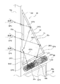
- FIG. 1 is a cross-sectional view showing a solar energy utilization window according to an embodiment of the present invention.
- FIG. 2 is an enlarged view of the first prism shown in FIG.
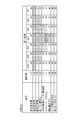
- FIG. 3 is a chart showing the relationship between the angle of the first base angle and the lower limit elevation angle when the refractive index of the first prism is changed when the apex angle AA of the first prism is 25 °.
- FIG. 4 is a chart showing the relationship between the angle of the first base angle and the lower limit elevation angle when the refractive index of the first prism is changed when the apex angle AA of the first prism is 30 °.
- FIG. 1 is a cross-sectional view showing a solar energy utilization window according to an embodiment of the present invention.
- FIG. 2 is an enlarged view of the first prism shown in FIG.
- FIG. 3 is a chart showing the relationship between the angle of the first base angle and the lower limit elevation angle when the refractive index of the first prism is changed when the ap
- FIG. 5 is a chart showing the relationship between the angle of the first base angle and the lower limit elevation angle when the refractive index of the first prism is changed when the apex angle AA of the first prism is 35 °.
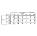
- FIG. 6 is a chart showing the relationship with the lower elevation angle when the angle of the apex angle is changed in the case where the refractive index of the first prism is approximately 1.41 and the first base angle is 90 °.
- FIG. 7 is a chart showing the relationship between the refractive index of the prism wall and the internal member of the first prism shown in FIG. 2 and the lower limit elevation angle.
- FIG. 8 is a cross-sectional view showing a solar energy utilization window according to the second embodiment.
- FIG. 9 is a partially enlarged cross-sectional view showing a solar energy utilization window according to a third embodiment.
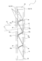
- FIG. 10 is a cross-sectional view showing an example where a solar energy utilization window is used as an inclined surface.
- FIG. 1 is a cross-sectional view showing a solar energy utilization window according to an embodiment of the present invention.
- FIG. 1 demonstrates the solar energy utilization window applicable as a window (it does not ask
- the solar energy utilization window 1 includes two plate members 10, a vacuum sealing member 20, a plurality of first prisms (triangular prisms) 30, and a plurality of energy collection units 40. , And a plurality of second prisms 50.
- the two plate members 10 are transparent plate members disposed substantially parallel to each other. These plate members 10 are made of, for example, a glass material, and among the two plate members 10, the outer side is the outer glass (transparent plate) 10a, and the indoor side is the inner glass (plate) 10b. .
- the vacuum sealing member 20 is interposed between the two plate members 10 at the peripheral end of the two plate members 10. By providing the vacuum sealing member 20 at the peripheral end of the two plate members 10, an internal space closed by the two plate members 10 and the vacuum sealing member 20 is formed.
- the internal space is in a vacuum state from the viewpoint of heat insulation, but is not limited thereto, and may be filled with a gas such as air, argon or krypton.
- Each of the plurality of first prisms 30 is configured by a prism (that is, a prism having a triangular prism shape) which is triangular in cross section.
- the first prisms 30 are disposed so as to face the outer glass 10 a such that the first side 30 a extends along the outer glass 10 a.
- the second side 30 b and the third side 30 c of the first prism 30 extend at a predetermined angle with respect to the first side 30 a.
- the second side 30 b is a side located vertically lower than the third side 30 c.
- FIG. 2 is an enlarged view of the first prism 30 shown in FIG.
- the first prism 30 is composed of a prism wall 31 which constitutes the outer wall of the first prism 30, and an internal member 32 made of a transparent liquid sealed inside the prism wall 31.
- the first prism 30 is not limited to the configuration shown in FIG. 2 and may be made of a solid glass material or resin material. Further, the internal member 32 may be gel-like or solid.
- the plurality of energy collection units 40 illustrated in FIG. 1 are devices that collect solar energy and use the solar energy for power generation, heating of another medium, heat transfer, etc. And heat transfer means. Each of the energy collection units 40 is provided to face the second side 30 b of the first prism 30.
- the plurality of second prisms 50 are prisms (i.e., prisms having a triangular prism shape) each having a triangular shape in cross section, and have the same shape and the same refractive index as the first prism 30.
- the second prisms 50 are oriented in a point symmetry obtained by rotating the first prism 30 by 180 °, and are provided one by one for each of the first prisms 30.
- light is refracted by the first prism 30, and distortion occurs in the view when viewed from the indoor side (that is, the scattered light SL is largely distorted).
- the second prism 50 may be configured of a prism wall and an internal member, or may be configured of a solid member.
- the second prisms 50 are disposed to face the inner glass 10b such that the fourth sides 50a extend along the inner glass 10b.
- the fifth side 50 b and the sixth side 50 c of the second prism 50 extend at a predetermined angle with respect to the fourth side 50 a.
- the fifth side 50 b is positioned vertically above the sixth side 50 c.
- the sixth side 50c faces the third side 30c of the first prism 30 adjacent in the horizontal direction, and the fifth side 50b sandwiches the energy collection unit 40 up and down. It faces the second side 30 b of the first prism 30 adjacent in the direction.
- the two plate members 10, the first prism 30, and the second prism 50 are disposed with a minute gap therebetween. Between these, interposed members such as minute pillars and grains are interposed so as to maintain a minute gap.
- the solar energy utilization window 1 has a laminated structure in the order of the outer glass 10a, the interposing member, the first prism 30, the interposing member, the second prism 50, the interposing member, and the inner glass 10b. Even if it has been said, it will be supported to withstand that pressure.
- the energy collection unit 40 is provided with a gap C ⁇ b> 1 with respect to the second side 30 b of the first prism 30.
- a fine intervening member may be interposed as described above, or the position may be maintained by other fixing means.
- the gap C1 is provided between the energy collecting unit 40 and the second side 30b of the first prism 30, so that a vacuum layer (or a gas layer) is formed between the two and heat of the energy collecting unit 40 The transition to the first prism 30 is suppressed.
- the energy collection unit 40 is also provided with a gap C2 with respect to the fifth side 50b of the second prism 50. Therefore, the energy collection unit 40 is provided separately from both the second side 30 b of the first prism 30 and the fifth side 50 b of the second prism 50. In order to maintain the gap C2, a fine interposition member may be interposed as described above, or the position may be maintained by other fixing means. In addition, a gap C2 is provided between the energy collecting unit 40 and the fifth side 50b of the second prism 50, so that a vacuum layer (or a gas layer) is formed between the two and the heat of the energy collecting unit 40 The transition to the prism 50 is also suppressed.
- the first prism 30 can transmit the sunlight entering the first prism 30 to the second side 30b. It is necessary not only to guide the light but also to emit the light without total reflection at the second side 30b, and the refractive index and each internal angle of the triangle are set to satisfy such conditions.
- the refractive index and the inside angles of the triangle are set so that three types of optical paths OP1 to OP3 are realized.
- the first optical path OP1 sunlight which has passed through the outer glass 10a and entered the first prism 30 from the first side 30a directly goes to the second side 30b. It reaches and comes out of the first prism 30 from the second side 30 b.
- the sunlight is totally reflected at the third side 30c, reaches the second side 30b, and exits the first prism 30 from the second side 30b.
- the third optical path OP3 is totally reflected in the order of the third side 30c and the first side 30a, reaches the second side 30b, and exits the first prism 30 from the second side 30b.
- the incident angle to the second side 30b of the first optical path OP1 needs to be less than the critical angle.
- the incident angle to the third side 30c of the second optical path OP2 needs to be equal to or larger than the critical angle, and the incident angle to the second side 30b after total reflection needs to be smaller than the critical angle.
- the incident angle to the third side 30c of the third optical path OP3 is equal to or greater than the critical angle, and the incident angle to the first side 30a after total reflection is equal to or greater than the critical angle.
- the angle of incidence on the side 30b of H must be less than the critical angle.
- an angle formed by the first side 30a and the third side 30c is referred to as an apex angle AA, and an angle formed by the second side 30b and the third side 30c is referred to as a first base angle.
- the angle formed by the first side 30a and the second side 30b is referred to as BA1, and is referred to as a second base angle BA2.
- the lower limit elevation angle is the lower limit of the elevation angle at which the first to third optical paths OP1 to OP3 are realized.
- the elevation angle refers to the angle between the direction of the line of sight when looking up at the sun and the orthogonal direction orthogonal to the two plate members 10, and when the solar energy utilization window 1 is used in an upright state, the sun It is the same as altitude. Therefore, when sunlight is incident on the first side 30a at an elevation angle equal to or more than the lower elevation angle, the first to third optical paths OP1 to OP3 are realized.
- the first base angle BA1 is 105 °, 100 °, 95 °, 90 °, 85 °, 80
- the lower elevation angle is 41 degrees at all of the degrees and 75 degrees.
- the first base angle BA1 is 105 °, 100 °, 95 °, 90 °, 85 °, 80 °, and 75 °. In all of the above, the lower limit elevation angle is 37 °.
- the lower limit elevation angle is 41 ° and the first base angle BA1 is 100 ° when the first base angle BA1 is 105 ° and 75 °.
- the lower elevation angle is 34 °.
- the first base angle BA1 is 105 °, 100 °, 95 °, 90 °, 85 °, 80 °, and The lower limit elevation angles become 44 °, 37 °, 33 °, 33 °, 33 °, 37 °, and 44 ° in the order of 75 °.
- the first base angle BA1 is 105 °, 100 °, 95 °, 90 °, 85 °, 80
- the lower limit elevation angles are 49 °, 41 °, 33 °, 31 °, 33 °, 41 °, and 49 ° in the order of ° and 75 °.
- the first base angle BA1 is 105 °, 100 °, 95 °, 90 °, 85 °, 80 °, and 75
- the lower elevation angles are 54 °, 45 °, 37 °, 30 °, 37 °, 45 °, and 54 °.
- the first base angle BA1 is in the order of 105 °, 100 °, 95 °, 90 °, 85 °, 80 °, and 75 °.
- the lower elevation angles are 65 °, 53 °, 44 °, 35 °, 44 °, 53 °, and 65 °.
- the first base angle BA1 is in the order of 105 °, 100 °, 95 °, 90 °, 85 °, 80 °, and 75 °.
- the lower elevation angles are 73 °, 58 °, 48 °, 38 °, 48 °, 58 °, and 73 °.
- the lower limit elevation angle is in the order of the first base angle BA1 of 105 °, 100 °, 95 °, 90 °, 85 °, 80 °, and 75 °.
- Is NG NG means 90 ° or more, which means the value does not make sense on the product. The same applies below), 70 °, 56 °, 45 °, 56 °, 70 °, And become NG.
- the lower limit elevation angle can be said to be preferable in energy acquisition because a smaller one can collect sunlight into the energy collection unit 40 in a wider angle range.
- the first prism 30 preferably has a refractive index of approximately 1.41 and a first base angle BA1 of 90 °.
- the first prism 30 may have a refractive index of approximately 1.41 and the first base angle BA1 may not be 90 °, and the minimum value of the lower limit elevation angle is + 10 ° (40 °).
- the refractive index and the internal angle may be set such that the lower elevation angle up to) is realized.
- the first base angle BA1 is 75 ° or more and 105 ° or less at the refractive index 1.25, and the first base angle BA1 is 80 ° or more and 100 at the refractive index 1.30 and 1.33. Or less, when the refractive index is 1.37 and 1.41, the first base angle BA1 is 85 ° or more and 95 ° or less, and the refractive index is 1.48 and 1.52 and the first base angle BA1 is 90 °,
- the lower limit elevation angle can be 40 ° or less, which is preferable.
- the reason why the lower limit elevation angle becomes the minimum value when the refractive index is approximately 1.41 (strictly ⁇ 2) is that the critical angle is 45 °.
- the critical angle is 45 °.
- Total reflection can be realized at 0 ° to 45 °, and total transmission can be realized at 45 ° to 90 °. That is, by equalizing the angle range of total reflection and total transmission, it is possible to prevent the tendency of only either total reflection or total transmission from becoming extremely strong, and to contribute to the minimization of the lower elevation angle. It has become.
- the first prism 30 is not limited to the one in which the refractive index and the inner angle are set so that the lower limit elevation angle of the minimum value + 10 ° of the lower limit elevation angle is realized.
- the refractive index is 1.59 or more and the first base angle BA1 is 105 ° or more and 75 ° or less. do it. That is, even if the first prism 30 has the refractive index and angle setting at which the three types of optical paths OP1 to OP3 are realized at elevation angles that the sun can take in consideration of time and season in the installation area and direction It is good.
- the first prism 30 is not limited to the case where the refractive index and angle setting are such that the three optical paths OP1 to OP3 are realized in all the altitude ranges that can be taken by the sun, but one of the altitude ranges that can be taken by the sun.
- the refractive index and angle setting may be such that the three types of optical paths OP1 to OP3 are realized only by the unit (for example, the highest altitude of the installation area).
- FIG. 3 shows the lower limit elevation angle when the apex angle AA is 25 °, when the angle of the apex angle AA changes, the value of the lower limit elevation angle also changes.
- FIG. 4 is a chart showing the relationship between the angle of the first base angle BA1 and the lower limit elevation angle when the refractive index of the first prism 30 is changed when the apex angle AA of the first prism 30 is 30 °. is there.
- the first base angle BA1 is 105 °, 100 °, 95 °, 90 °, 85 °, 80
- the lower limit elevation angle is 35 degrees at all of the degrees and 75 degrees.
- the first base angle BA1 is 105 °, 100 °, 95 °, 90 °, 85 °, 80 °, and 75 °. In all of the above, the lower limit elevation angle is 30 °.
- the lower limit elevation angle is 33 ° and the first base angle BA1 is 100 ° when the first base angle BA1 is 105 ° and 75 °.
- the lower limit elevation angle is 27 ° at all of 95 °, 90 °, 85 °, and 80 °.
- the first base angle BA1 is 105 °, 100 °, 95 °, 90 °, 85 °, 80 °, and The lower limit elevation angles become 37 °, 29 °, 26 °, 26 °, 26 °, 29 °, and 37 ° in the order of 75 °.
- the first base angle BA1 is 105 °, 100 °, 95 °, 90 °, 85 °, 80
- the lower elevation angles are 41 °, 33 °, 26 °, 24 °, 26 °, 33 °, and 41 ° in the order of ° and 75 °.
- the first base angle BA1 is 105 °, 100 °, 95 °, 90 °, 85 °, 80 °, and 75
- the lower limit elevation angles are 45 degrees, 37 degrees, 29 degrees, 22 degrees, 29 degrees, 37 degrees, and 45 degrees.
- the first base angle BA1 is in the order of 105 °, 100 °, 95 °, 90 °, 85 °, 80 °, and 75 °.
- the lower elevation angles are 53 °, 44 °, 35 °, 27 °, 35 °, 44 °, and 53 °.
- the first base angle BA1 is in the order of 105 °, 100 °, 95 °, 90 °, 85 °, 80 °, and 75 °.
- the lower elevation angles are 58 °, 48 °, 38 °, 30 °, 38 °, 48 °, and 58 °.
- the lower limit elevation angle is in the order of the first base angle BA1 of 105 °, 100 °, 95 °, 90 °, 85 °, 80 °, and 75 °.
- the first base angle BA1 of 105 °, 100 °, 95 °, 90 °, 85 °, 80 °, and 75 °.
- the lower limit elevation angle becomes the minimum value (22 °) when the refractive index is approximately 1.41 and the first base angle BA1 is 90 °. .
- the angle of the apex angle AA is 30 °, it is preferable to set the refractive index and the inner angle of the first prism 30 so that the lower limit elevation angle is 32 ° or less.
- FIG. 5 is a chart showing the relationship between the angle of the first base angle BA1 and the lower limit elevation angle when the refractive index of the first prism 30 is changed when the apex angle AA of the first prism 30 is 35 °. is there.
- the first base angle BA1 is 105 °, 100 °, 95 °, 90 °, 85 °, 80
- the lower limit elevation angle is 29 degrees at all of the degrees and 75 degrees.
- the first base angle BA1 is 105 °, 100 °, 95 °, 90 °, 85 °, 80 °, and 75 °. In all of the above, the lower limit elevation angle is 23 °.
- the lower limit elevation angle is 27 ° and the first base angle BA1 is 100 ° when the first base angle BA1 is 105 ° and 75 °.
- the lower limit elevation angle is 21 ° at all of 95 °, 90 °, 85 °, and 80 °.
- the first base angle BA1 is 105 °, 100 °, 95 °, 90 °, 85 °, 80 °
- the lower limit elevation angles are 29 °, 22 °, 19 °, 19 °, 19 °, 22 °, and 29 ° in the order of 75 °.
- the first base angle BA1 is 105 °, 100 °, 95 °, 90 °, 85 °, 80
- the lower limit elevation angles are 33 °, 26 °, 19 °, 17 °, 19 °, 26 °, and 33 ° in the order of ° and 75 °.
- the first base angle BA1 is 105 °, 100 °, 95 °, 90 °, 85 °, 80 °, and 75
- the lower limit elevation angles are 37 degrees, 29 degrees, 22 degrees, 14 degrees, 22 degrees, 29 degrees, and 37 degrees.
- the first base angle BA1 is in the order of 105 °, 100 °, 95 °, 90 °, 85 °, 80 °, and 75 °.
- the lower elevation angles are 44 °, 35 °, 27 °, 19 °, 27 °, 35 °, and 44 °.
- the first base angle BA1 is in the order of 105 °, 100 °, 95 °, 90 °, 85 °, 80 °, and 75 °.
- the lower elevation angles are 48 °, 38 °, 30 °, 22 °, 30 °, 38 °, and 48 °.
- the lower limit elevation angle is in the order of the first base angle BA1 of 105 °, 100 °, 95 °, 90 °, 85 °, 80 °, and 75 °.
- the first base angle BA1 of 105 °, 100 °, 95 °, 90 °, 85 °, 80 °, and 75 °.
- the lower limit elevation angle becomes the minimum value (14 °) when the refractive index is approximately 1.41 and the first base angle BA1 is 90 °. . Therefore, when the angle of the apex angle AA is 30 °, it is preferable to set the refractive index and the inner angle of the first prism 30 so that the lower limit elevation angle is 24 ° or less.
- FIG. 6 is a chart showing the relationship with the lower elevation angle when the angle of the apex angle AA is changed when the refractive index of the first prism 30 is approximately 1.41 and the first base angle BA1 is 90 °. is there.
- the lower limit elevation angle is 46 ° when the apex angle AA is 15 °.
- the lower limit elevation angle when the apex angle AA is 20 ° is 37 °.
- the lower limit elevation angles when the apex angles AA are 25 °, 30 ° and 35 ° are 30 °, 22 ° and 14 ° in order as described with reference to FIGS.
- the lower limit elevation angles when the apex angle AA is 40 ° and 45 ° are 8 ° and 1 °.
- the apex angle AA is brought close to 45 ° in order to reduce the lower elevation angle, the height when the first side 30 a is at the base increases, and the thickness of the solar energy utilization window 1 tends to increase. is there.
- the elevation angle (incident angle with respect to the elevation) when the south middle altitude of the sun is lowest is 32 °. Therefore, when the solar energy utilization window 1 is used on the south surface in Japan, if the apex angle AA is set to 20 ° or 25 °, the utilization efficiency of the solar energy can be enhanced, and the thinness of the solar energy utilization window 1 It is possible to achieve both daylighting and viewability by indirect light. Further, to increase the utilization efficiency of solar energy at sunrise and sunset such as the east and west faces, it is sufficient to increase the apex angle AA.
- the solar energy utilization window 1 for south face (for the north face in the southern hemisphere) has a smaller apex angle AA than the solar energy utilization window 1 for east face and west face.
- the apex angle AA is preferably 20 ° or more and 35 ° or less.
- FIG. 7 is a chart showing the relationship between the refractive index of the liquid that is the prism wall 31 and the internal member 32 of the first prism 30 shown in FIG. 2 and the lower limit elevation angle.
- the apex angle AA of the first prism 30 is 30 °
- the first base angle BA1 is 90 °.
- the refractive index of the prism wall 31 and the internal member 32 of the first prism 30 is different, the refractive index of the prism wall 31 does not affect the refractive index of the entire first prism 30. The details will be described below.
- the refractive index of the inner member 32 is 1.33, in all of the refractive indexes of the prism wall 31 is 1.33, 1.37, 1.41, 1.48, 1.52, and 1.59.
- the lower elevation angle was 26 °.
- the refractive index of the inner member 32 is 1.37
- the refractive index of the prism wall 31 is 1.33, 1.37, 1.41, 1.48, 1.52, and 1.59.
- the lower elevation angle was 24 °.
- the lower limit elevation angle is 22 ° when the refractive index of the inner member 32 is 1.41
- the lower limit elevation angle is 22 ° when the refractive index of the inner member 32 is 1.48.
- the lower limit elevation angle is 30 °.
- the lower limit elevation angle is 35 °.
- the refractive index of the first prism 30 is controlled by the refractive index of the inner member 32 and is not influenced by the refractive index of the prism wall 31.
- three types of optical paths OP1 to OP3 are realized by setting the refractive index and the inner angle of the first prism 30. For this reason, the sunlight which has passed through the outer glass 10a and entered the first prism 30 from the first side 30a reaches the second side 30b directly and is out of the first prism 30 from the second side 30b. A first optical path OP1 to be emitted is formed. Furthermore, the sunlight is also totally reflected by the third side 30 c to reach the second side 30 b and form a second optical path OP 2 which is emitted from the second side 30 b to the outside of the first prism 30.
- the sunlight emitted from the second side 30 b is incident on the energy collection unit 40 and energy is used.
- the energy collection unit 40 is not in contact with the first prism 30, and is disposed with a gap C1. For this reason, the heat of the energy collection part 40 becomes difficult to transfer to the 1st prism 30, and solar heat can be used more efficiently.
- the energy collection part 40 is installed on both sides of the predetermined
- the first prism 30 has the refractive index and the respective internal angles of the triangle set so that the three types of optical paths OP1 to OP3 exist, the sun which has entered the first prism 30 from the first side 30a The light comes out of the first prism 30 from the second side 30 b directly or through total reflection of the third side 30 c and the first side 30 a.
- the sunlight is also collected in the energy collection unit 40 disposed with a predetermined gap C1. be able to. Therefore, it is possible to collect solar light in the energy collection unit 40 and to use solar energy more efficiently while suppressing heat transfer.
- the first prism 30 has the transparent prism wall 31 constituting the outer wall of the first prism 30 and the transparent internal member 32 sealed inside the prism wall 31, the first prism 30
- the refractive index of 30 is dominated by the inner member 32, is less susceptible to the prism wall 31, and the first prism 30 with the desired refractive index can be made easier to produce.
- the lower limit elevation angle of sunlight when the three optical paths OP1 to OP3 are realized for sunlight entering from the first side 30a has a refractive index of about 1.41, and The minimum value is obtained when the angle formed by the second side 30 b and the third side 30 c is 90 °.
- the inventor found that the lower limit elevation angle becomes the minimum value when the first prism 30 is approximately 1.41 and the angle is 90 °. For this reason, by setting the refractive index and the above-mentioned angle to be a value of + 10 ° or less than the minimum value, the lower limit elevation angle is brought close to the minimum value, and sunlight is made in a wider angle range (sun elevation angle). Can be provided to the energy collection unit 40.
- the second prism 50 having the same shape as the first prism 30 and arranged in the direction of point symmetry with the first prism 30 is further provided, an image restoration effect can be provided by the second prism 50.
- the energy collection unit 40 is provided between the second side 30 b of the first prism 30 and the fifth side 50 b of the second prism 50 so as to be separated from both. For this reason, the heat of the energy collection part 40 becomes difficult to transfer also to the 2nd prism 50, and solar energy can be used much more efficiently.
- the solar energy utilization window according to the second embodiment is the same as that of the first embodiment, but the configuration is partially different.
- elements that are the same as or similar to those of the first embodiment are assigned the same reference numerals and descriptions thereof will be omitted.
- FIG. 8 is a cross-sectional view showing a solar energy utilization window according to the second embodiment.
- the energy collection unit 40 has the same configuration as the second prism 50 according to the first embodiment.
- the energy collecting unit 40 is substantially transparent (transparent except for the selective absorption unit 41 described later), has the same shape as the first prism 30 in a cross sectional view, and is in point symmetry with the first prism 30 Is located in However, the portion corresponding to the fifth side 50b of the energy collection unit 40 has a large absorptivity in the sunlight wavelength region (0.3 to 2.5 ⁇ m), and the emissivity in the infrared wavelength region (3.0 to 20 ⁇ m) Is a small selective absorption section 41. In addition, it may replace with the selective absorption part 41, and a solar cell may be provided.
- Such an energy collection unit 40 is disposed in pair with the first prism 30. That is, in the energy collection unit 40, a portion corresponding to the fifth side 50b is disposed to face the second side 30b of the first prism 30.
- the energy collection unit 40 also functions as a transparent prism that refracts light, etc., as in the second prism 50 shown in the first embodiment, except for the selective absorption unit 41, so a so-called image can be obtained. It will bring out the recovery effect.
- the energy collection unit 40 can take various forms as in the first prism 30 described in the first embodiment.
- the prism wall and the liquid (heat medium It can also consist of an internal member which consists of.
- the heated heat medium is used for other devices. It can be done.
- the energy collection part 40 may be comprised by the hygroscopic solid member.
- moisture can be released from the energy collection unit 40 heated by the first prism 30, and a humidifying effect can be provided in the room.
- the front and back of the two plate members 10 be configured to be reversible, and that the energy collecting unit 40 be capable of accumulating moisture by inverting the front and back at night.
- the inner glass 10b is made of a water vapor permeable material.
- the first prism 30 is configured by the prism wall 31 and the internal member 32 made of hygroscopic liquid
- the energy collecting unit 40 is also similarly configured by the prism wall and the internal member made of hygroscopic liquid It is also good.
- the energy collection unit 40 releases moisture and the first prism 30 absorbs moisture. Can be performed continuously.
- the prism wall of the energy collection unit 40, the prism wall 31 of the first prism 30, the outer glass 10a and the inner glass 10b are made of water vapor permeable, and the first prism 30 and the energy collection unit 40 It is preferable to provide a membrane which does not allow water vapor to pass therebetween.
- the prism wall 31 of the first prism 30 and the outer glass 10a may be made of a material that does not transmit water vapor.
- the outside air is sent into the first prism 30, and piping and a pump are provided to discharge moisture in the first prism 30 and discharge dry air bubbles to the outside air again.
- the prism wall of the energy collection unit 40 and the inner glass 10b may be made of a material that does not transmit water vapor.
- the solar energy utilization window 2 which concerns on 2nd Embodiment, solar energy can be used more efficiently similarly to 1st Embodiment.
- the first prism 30 when the first prism 30 is configured by the transparent prism wall 31 and the transparent internal member 32, the first prism 30 having a desired refractive index can be easily produced. Furthermore, by setting the refractive index and the above angle so that the value is + 10 ° or less than the minimum value, the lower limit elevation angle is brought close to the minimum value, and energy of sunlight is increased in a wider angle range (sun elevation angle) The solar energy utilization window 2 which can be collected to the collection part 40 can be provided.
- the energy collection unit 40 has the same shape as the first prism 30 in a cross-sectional view, and is disposed in a direction that is point symmetrical with the first prism 30. Since the absorbing portion 41) is non-transparent and the remaining portion is transparent, it is possible to make the energy collecting unit 40 have the function of the image restoration prism by using the transparent portion.
- the energy collection unit 40 is constituted of, for example, a prism wall and an internal member of a liquid (heat medium) as in the first prism 30, for example, the heat medium may be transferred to a regenerator of an absorption refrigerator. it can. Further, by forming the energy collection unit 40 with a hygroscopic member, it is possible to bring about a humidifying effect in the room.
- the first prism 30 is configured by the prism wall 31 and the internal member 32 made of a hygroscopic liquid, and the energy collection unit 40 is also configured the same, and the first prism 30 and the energy collection unit 40 are hygroscopic. By circulating the liquid, for example, moisture can be released from the energy collection unit 40 and the first prism 30 can continuously perform the operation of absorbing the moisture.
- the solar energy utilization window according to the third embodiment is the same as that of the first embodiment, but the configuration is partially different.
- elements that are the same as or similar to those of the first embodiment are assigned the same reference numerals and descriptions thereof will be omitted.
- FIG. 9 is a partially enlarged cross-sectional view showing a solar energy utilization window according to a third embodiment.
- each of the plurality of energy collection units 40 has a gap C1 with respect to the first prism 30, and a gap C2 with respect to the second prism 50.
- the solar energy utilization window 3 according to the third embodiment includes the movement mechanism 60 for moving the plurality of energy collection units 40 between the second side 30 b and the fifth side 50 b. .
- the configuration is not particularly limited, but for example, the power to move the energy collection unit 40 It is comprised from the motor used as a source, and the moving rail of the energy collection part 40.
- the moving mechanism 60 is capable of moving the energy collection unit 40 to a position where the second side 30 b and the fifth side 50 b are brought into contact with each other. Specifically, the moving mechanism 60 can move the energy collection unit 40 to a position indicated by reference numeral 40-1 and make it contact the second side 30b of the first prism 30. Similarly, the moving mechanism 60 can move the energy collection unit 40 to the position indicated by reference numeral 40-2 and make it contact the fifth side 50b of the second prism 50.
- the solar energy utilization window 3 according to the third embodiment can heat one of the first prism 30 and the second prism 50.
- the solar energy utilization window 3 is operable as follows.
- the energy collection unit 40 when the energy collection unit 40 is brought into contact with the fifth side 50 b of the second prism 50 by the moving mechanism 60 in the case where the second prism 50 has a hygroscopic member or liquid, the hygroscopic member Can be heated to release moisture.
- the energy collecting unit 40 is disposed on the second side 30 b of the first prism 30.
- moisture can be released in the first prism 30, and the hygroscopic liquid from which moisture is released can be supplied to the second prism 50, and moisture can be absorbed in the second prism 50.
- the solar energy utilization window 3 according to the third embodiment, solar energy can be used (more efficiently) more efficiently, as in the first embodiment.
- the first prism 30 is configured by the transparent prism wall 31 and the transparent internal member 32, the first prism 30 having a desired refractive index can be easily produced.
- the refractive index and the above angle so that the value is + 10 ° or less than the minimum value, the lower limit elevation angle is brought close to the minimum value, and energy of sunlight is increased in a wider angle range (sun elevation angle)
- a solar energy utilization window 3 that can be collected in the collection unit 40 can be provided.
- one of the prisms 30 and 50 is heated because it further includes the moving mechanism 60 that enables the energy collection unit 40 to be separated on the second side 30 b and the fifth side 50 b.
- the energy collection unit 40 can be brought into contact with the prisms 30 and 50, and the functions can be further diversified.
- the solar energy utilization window 1 is not limited to the elevation surface and may be used for an inclined surface (for example, a roof surface).
- FIG. 10 is a cross-sectional view showing an example where the solar energy utilization windows 1 to 3 are used as the inclined surface. As shown in FIG. 10, the solar energy utilization windows 1 to 3 may be used, for example, on a slope inclined to the north side in Japan. Even in such a case, three types of optical paths OP1 to OP3 can be realized from the relationship with the lower elevation angle at the time of elevation.
- the solar energy utilization windows 1 to 3 have a two-layer structure of the outer glass 10a and the inner glass 10b in the above embodiment, the solar energy utilization windows 1 to 3 may be provided with a plate of third or more layers.
- the plurality of energy collection units 40 move integrally (move the same) by the moving mechanism 60, but the invention is not limited thereto. Only the energy collecting unit 40 of one unit may be moved in a direction different from that of the other energy collecting unit 40. That is, each energy collection part 40 may be moved to a different position.
- Solar energy utilization window (solar energy utilization device) 10: Two sheets of plate material 10a: Outer glass (plate material of transparency) 10b: Inner glass (plate material) 20: Vacuum sealing member 30: First prism (triangular prism) 30a: first side 30b: second side 30c: third side 31: prism wall 32: internal member 40: energy collecting portion 41: selective absorption portion 50: second prism (second triangular prism) 50a: fourth side 50b: fifth side 50c: sixth side 60: moving mechanism AA: apex angle BA1: first base angle BA2: second base angle C1, C2: gap OP1 to OP3: three types Light path SL: Scattered light
Landscapes
- Engineering & Computer Science (AREA)
- Physics & Mathematics (AREA)
- Mechanical Engineering (AREA)
- General Engineering & Computer Science (AREA)
- Sustainable Energy (AREA)
- Thermal Sciences (AREA)
- Chemical & Material Sciences (AREA)
- Combustion & Propulsion (AREA)
- Life Sciences & Earth Sciences (AREA)
- Sustainable Development (AREA)
- Civil Engineering (AREA)
- Structural Engineering (AREA)
- General Physics & Mathematics (AREA)
- Optics & Photonics (AREA)
- Optical Elements Other Than Lenses (AREA)
- Special Wing (AREA)
- Photovoltaic Devices (AREA)
- Non-Portable Lighting Devices Or Systems Thereof (AREA)
Abstract
Description
10 :2枚の板材
10a :外ガラス(透明性の板材)
10b :内ガラス(板材)
20 :真空封止部材
30 :第1プリズム(三角柱プリズム)
30a :第1の辺
30b :第2の辺
30c :第3の辺
31 :プリズム壁
32 :内部部材
40 :エネルギー収集部
41 :選択吸収部
50 :第2プリズム(第2三角柱プリズム)
50a :第4の辺
50b :第5の辺
50c :第6の辺
60 :移動機構
AA :頂角
BA1 :第1底角
BA2 :第2底角
C1,C2 :隙間
OP1~OP3 :3種の光路
SL :散乱光
Claims (6)
- 板材と、当該板材よりも太陽光の入射側において当該板材と略平行配置される透明性の板材とからなる2枚の板材と、
前記2枚の板材の間に配置されると共に、断面視して前記透明性の板材に沿う第1の辺と前記第1の辺に対して角度を有する第2及び第3の辺からなる透明性の三角柱プリズムと、
前記第2及び第3の辺のうち、下方側の辺となる第2の辺に対して、所定の隙間を挟んで設置され、太陽エネルギーを収集するエネルギー収集部と、を備え、
前記三角柱プリズムは、前記透明性の板材を通過して前記第1の辺から当該三角柱プリズム内に進入した太陽光のうち、直接前記第2の辺に到達して前記第2の辺から当該三角柱プリズム外に出るものと、前記第3の辺で全反射して前記第2の辺に到達して前記第2の辺から当該三角柱プリズム外に出るものと、前記第3の辺及び前記第1の辺の順に全反射した後に前記第2の辺に到達して前記第2の辺から当該三角柱プリズム外に出るものとの3種の光路が存在するように屈折率と三角の各内角とが設定されている
太陽エネルギー利用器。 - 前記三角柱プリズムは、当該三角柱プリズムの外壁を構成する透明性のプリズム壁と、前記プリズム壁の内部に封入される透明性の内部部材と、を有する
請求項1に記載の太陽エネルギー利用器。 - 前記三角柱プリズムは、前記第1の辺から進入する太陽光について前記3種の光路が実現されるときの太陽光の下限仰角が、屈折率が略1.41であり、前記第2の辺と前記第3の辺とがなす角度が90°であるときに最小値となるものであって、当該最小値よりも+10°以下の値となるように、屈折率及び前記第2の辺と前記第3の辺とがなす角度が設定されている
請求項1又は請求項2に記載の太陽エネルギー利用器。 - 前記エネルギー収集部は、断面視状態で、前記三角柱プリズムと略同一形状であり、前記三角柱プリズムと点対称となる向きに配置されており、一部分が非透明性で残部が透明性である
請求項1から請求項3のいずれか1項に記載の太陽エネルギー利用器。 - 断面視状態で、前記三角柱プリズムと同一形状であり、前記2枚の板材に沿う第4の辺と前記第4の辺に対して角度を有する第5及び第6の辺からなり、前記三角柱プリズムと点対称となる向きに配置された透明性の第2三角柱プリズムをさらに備え、
前記2枚の板材は、双方が透明性の板材であり、
前記エネルギー収集部は、前記三角柱プリズムの前記第2の辺と、前記第2三角柱プリズムの第5及び第6の辺のうち、上方側の辺となる第5の辺との間において、双方から離間して設けられている
請求項1から請求項3のいずれか1項に記載の太陽エネルギー利用器。 - 前記第2の辺と前記第5の辺との間で前記エネルギー収集部を移動可能であって、前記エネルギー収集部を前記第2の辺と前記第5の辺とにそれぞれ切離可能とする移動機構をさらに備える
請求項5に記載の太陽エネルギー利用器。
Priority Applications (4)
| Application Number | Priority Date | Filing Date | Title |
|---|---|---|---|
| AU2018394843A AU2018394843B2 (en) | 2017-12-26 | 2018-12-10 | Solar energy utilization device |
| EP18896250.0A EP3734184A4 (en) | 2017-12-26 | 2018-12-10 | SOLAR ENERGY APPLIANCE |
| CN201880084064.0A CN111566416B (zh) | 2017-12-26 | 2018-12-10 | 太阳能利用设备 |
| US16/911,564 US11936336B2 (en) | 2017-12-26 | 2020-06-25 | Solar energy utilization device |
Applications Claiming Priority (2)
| Application Number | Priority Date | Filing Date | Title |
|---|---|---|---|
| JP2017-248816 | 2017-12-26 | ||
| JP2017248816A JP7036587B2 (ja) | 2017-12-26 | 2017-12-26 | 太陽エネルギー利用器 |
Related Child Applications (1)
| Application Number | Title | Priority Date | Filing Date |
|---|---|---|---|
| US16/911,564 Continuation US11936336B2 (en) | 2017-12-26 | 2020-06-25 | Solar energy utilization device |
Publications (1)
| Publication Number | Publication Date |
|---|---|
| WO2019131087A1 true WO2019131087A1 (ja) | 2019-07-04 |
Family
ID=67067251
Family Applications (1)
| Application Number | Title | Priority Date | Filing Date |
|---|---|---|---|
| PCT/JP2018/045322 WO2019131087A1 (ja) | 2017-12-26 | 2018-12-10 | 太陽エネルギー利用器 |
Country Status (6)
| Country | Link |
|---|---|
| US (1) | US11936336B2 (ja) |
| EP (1) | EP3734184A4 (ja) |
| JP (1) | JP7036587B2 (ja) |
| CN (1) | CN111566416B (ja) |
| AU (1) | AU2018394843B2 (ja) |
| WO (1) | WO2019131087A1 (ja) |
Cited By (1)
| Publication number | Priority date | Publication date | Assignee | Title |
|---|---|---|---|---|
| WO2021205390A1 (en) * | 2020-04-09 | 2021-10-14 | Balaji Lakshmikanth Bangolae | A light redirecting prism, a redirecting prismatic wall and a solar panel incorporating the same |
Families Citing this family (5)
| Publication number | Priority date | Publication date | Assignee | Title |
|---|---|---|---|---|
| JP7039352B2 (ja) * | 2018-03-27 | 2022-03-22 | 矢崎エナジーシステム株式会社 | 多段型プリズム窓 |
| JP7043342B2 (ja) * | 2018-05-16 | 2022-03-29 | 矢崎エナジーシステム株式会社 | 多段型プリズム窓 |
| WO2022178826A1 (zh) * | 2021-02-26 | 2022-09-01 | 博立码杰通讯(深圳)有限公司 | 太阳能利用装置 |
| AT525493A1 (de) * | 2021-10-01 | 2023-04-15 | Ess Holding Gmbh | Vorrichtung zum photothermischen Beheizen von thermoelektrischen Generatoren |
| AT525494A1 (de) * | 2021-10-01 | 2023-04-15 | Ess Holding Gmbh | Vorrichtung zum photothermischen Beheizen von thermoelektrischen Generatoren |
Citations (7)
| Publication number | Priority date | Publication date | Assignee | Title |
|---|---|---|---|---|
| JPS5948505U (ja) * | 1982-09-21 | 1984-03-31 | 坂本 開六 | 液体プリズム |
| JPH06275859A (ja) * | 1993-03-24 | 1994-09-30 | Omron Corp | 太陽電池用集光装置 |
| JPH08211207A (ja) * | 1995-02-01 | 1996-08-20 | Pioneer Electron Corp | プリズム装置および液晶プロジェクション装置 |
| JP2003502843A (ja) * | 1999-06-10 | 2003-01-21 | スリーエム イノベイティブ プロパティズ カンパニー | 放射エネルギーを収集するためのパネル状構造物 |
| WO2009121180A1 (en) * | 2008-04-02 | 2009-10-08 | Morgan Solar Inc. | Solar panel window |
| JP2013508582A (ja) | 2009-10-21 | 2013-03-07 | ピタゴラス ソーラー インコーポレーテッド | 窓 |
| DE102012102752A1 (de) * | 2011-12-26 | 2013-06-27 | Kaustik-Solar Gmbh | Vorrichtung und Verfahren zum photovoltaischen Absorbieren von einfallendem Licht |
Family Cites Families (15)
| Publication number | Priority date | Publication date | Assignee | Title |
|---|---|---|---|---|
| AU522513B2 (en) * | 1977-06-24 | 1982-06-10 | Unisearch Limited | Solar concentrator & radiation distributor |
| US4344417A (en) * | 1980-10-21 | 1982-08-17 | Jan Malecek | Solar energy collector |
| US20070227581A1 (en) * | 2006-03-28 | 2007-10-04 | Zupei Chen | Concentrator solar cell module |
| US20080128016A1 (en) * | 2006-11-08 | 2008-06-05 | Silicon Valley Solar, Inc. | Parallel Aperture Prismatic Light Concentrator |
| CN101206080A (zh) * | 2006-12-19 | 2008-06-25 | 上海太阳能科技有限公司 | 太阳能热水器集热器 |
| JP5076194B2 (ja) | 2007-07-20 | 2012-11-21 | スタンレー電気株式会社 | 光照射装置 |
| US20090101207A1 (en) * | 2007-10-17 | 2009-04-23 | Solfocus, Inc. | Hermetic receiver package |
| CN102027183A (zh) * | 2008-04-02 | 2011-04-20 | 摩根阳光公司 | 太阳能电池板窗户 |
| TW201023379A (en) * | 2008-12-03 | 2010-06-16 | Ind Tech Res Inst | Light concentrating module |
| CN102272948A (zh) * | 2008-12-31 | 2011-12-07 | 毕达哥拉斯太阳公司 | 太阳光棱镜收集器 |
| JP5508946B2 (ja) | 2010-06-16 | 2014-06-04 | デクセリアルズ株式会社 | 光学体、窓材、建具、日射遮蔽装置、および建築物 |
| US20120090681A1 (en) * | 2010-10-14 | 2012-04-19 | Millennium Communication Co., Ltd. | Package structure of concentrated photovoltaic cell and fabrication method thereof |
| BR112013017614A2 (pt) * | 2011-01-10 | 2016-10-18 | Pythagoras Solar Inc | janela |
| EP2860575B1 (en) | 2012-06-07 | 2017-09-27 | Panasonic Intellectual Property Management Co., Ltd. | Light deflector, method for manufacturing light deflector, and liquid-crystal display |
| JP6275859B2 (ja) * | 2014-02-28 | 2018-02-07 | ヘルマン ウルトラシャルテクニーク ゲーエムベーハー ウント コー.カーゲーHerrmann Ultraschalltechnik Gmbh & Co.Kg | 力センサを有する超音波加工デバイス |
-
2017
- 2017-12-26 JP JP2017248816A patent/JP7036587B2/ja active Active
-
2018
- 2018-12-10 EP EP18896250.0A patent/EP3734184A4/en active Pending
- 2018-12-10 AU AU2018394843A patent/AU2018394843B2/en active Active
- 2018-12-10 WO PCT/JP2018/045322 patent/WO2019131087A1/ja unknown
- 2018-12-10 CN CN201880084064.0A patent/CN111566416B/zh active Active
-
2020
- 2020-06-25 US US16/911,564 patent/US11936336B2/en active Active
Patent Citations (7)
| Publication number | Priority date | Publication date | Assignee | Title |
|---|---|---|---|---|
| JPS5948505U (ja) * | 1982-09-21 | 1984-03-31 | 坂本 開六 | 液体プリズム |
| JPH06275859A (ja) * | 1993-03-24 | 1994-09-30 | Omron Corp | 太陽電池用集光装置 |
| JPH08211207A (ja) * | 1995-02-01 | 1996-08-20 | Pioneer Electron Corp | プリズム装置および液晶プロジェクション装置 |
| JP2003502843A (ja) * | 1999-06-10 | 2003-01-21 | スリーエム イノベイティブ プロパティズ カンパニー | 放射エネルギーを収集するためのパネル状構造物 |
| WO2009121180A1 (en) * | 2008-04-02 | 2009-10-08 | Morgan Solar Inc. | Solar panel window |
| JP2013508582A (ja) | 2009-10-21 | 2013-03-07 | ピタゴラス ソーラー インコーポレーテッド | 窓 |
| DE102012102752A1 (de) * | 2011-12-26 | 2013-06-27 | Kaustik-Solar Gmbh | Vorrichtung und Verfahren zum photovoltaischen Absorbieren von einfallendem Licht |
Non-Patent Citations (1)
| Title |
|---|
| See also references of EP3734184A4 |
Cited By (1)
| Publication number | Priority date | Publication date | Assignee | Title |
|---|---|---|---|---|
| WO2021205390A1 (en) * | 2020-04-09 | 2021-10-14 | Balaji Lakshmikanth Bangolae | A light redirecting prism, a redirecting prismatic wall and a solar panel incorporating the same |
Also Published As
| Publication number | Publication date |
|---|---|
| AU2018394843A1 (en) | 2020-07-16 |
| CN111566416B (zh) | 2022-02-11 |
| US11936336B2 (en) | 2024-03-19 |
| EP3734184A4 (en) | 2021-01-06 |
| EP3734184A1 (en) | 2020-11-04 |
| JP2019113284A (ja) | 2019-07-11 |
| CN111566416A (zh) | 2020-08-21 |
| AU2018394843B2 (en) | 2021-06-10 |
| JP7036587B2 (ja) | 2022-03-15 |
| US20200328717A1 (en) | 2020-10-15 |
Similar Documents
| Publication | Publication Date | Title |
|---|---|---|
| WO2019131087A1 (ja) | 太陽エネルギー利用器 | |
| JP6600919B2 (ja) | 集光機構、太陽光発電装置及び窓構造 | |
| US20150083195A1 (en) | Transparent solar energy collector | |
| JP5493150B2 (ja) | 調光透明窓用部材 | |
| WO2011101682A2 (en) | Concentrating evacuated photovoltaic glazing panel | |
| US11162712B2 (en) | Solar light utilization apparatus and solar light utilization system | |
| WO2015015041A1 (es) | Panel solar tridimensional térmico o fotovoltaico con holografía incorporada | |
| US20210017810A1 (en) | Retroreflective window | |
| JP2017085750A (ja) | 窓用太陽電池モジュール及び窓 | |
| US11572735B2 (en) | Multistage prism window | |
| TW202029635A (zh) | 鋸齒形太陽能模組 | |
| KR20020047766A (ko) | 투명 단열재를 이용한 평판형 태양열 집열기 | |
| JP6839157B2 (ja) | 外壁材 | |
| EP3042133B1 (en) | Facade module element with an integrated solar collector system | |
| WO2017178989A1 (en) | Holographic film of particular application in photovoltaic panels, in solar thermal panels and in solar light diffusion panels | |
| TWI478363B (zh) | 雙面薄膜太陽能電池模組 | |
| PL191055B1 (pl) | Przetwornik energii słonecznej na cieplną |
Legal Events
| Date | Code | Title | Description |
|---|---|---|---|
| 121 | Ep: the epo has been informed by wipo that ep was designated in this application |
Ref document number: 18896250 Country of ref document: EP Kind code of ref document: A1 |
|
| NENP | Non-entry into the national phase |
Ref country code: DE |
|
| ENP | Entry into the national phase |
Ref document number: 2018394843 Country of ref document: AU Date of ref document: 20181210 Kind code of ref document: A |
|
| ENP | Entry into the national phase |
Ref document number: 2018896250 Country of ref document: EP Effective date: 20200727 |