WO2019130995A1 - ノイズ吸収熱伝導シートおよびこれを用いた電子機器 - Google Patents
ノイズ吸収熱伝導シートおよびこれを用いた電子機器 Download PDFInfo
- Publication number
- WO2019130995A1 WO2019130995A1 PCT/JP2018/044331 JP2018044331W WO2019130995A1 WO 2019130995 A1 WO2019130995 A1 WO 2019130995A1 JP 2018044331 W JP2018044331 W JP 2018044331W WO 2019130995 A1 WO2019130995 A1 WO 2019130995A1
- Authority
- WO
- WIPO (PCT)
- Prior art keywords
- double
- sided tape
- metal layer
- protective film
- graphite sheet
- Prior art date
- Legal status (The legal status is an assumption and is not a legal conclusion. Google has not performed a legal analysis and makes no representation as to the accuracy of the status listed.)
- Ceased
Links
Images

Classifications
-
- B—PERFORMING OPERATIONS; TRANSPORTING
- B32—LAYERED PRODUCTS
- B32B—LAYERED PRODUCTS, i.e. PRODUCTS BUILT-UP OF STRATA OF FLAT OR NON-FLAT, e.g. CELLULAR OR HONEYCOMB, FORM
- B32B15/00—Layered products comprising a layer of metal
- B32B15/04—Layered products comprising a layer of metal comprising metal as the main or only constituent of a layer, which is next to another layer of the same or of a different material
-
- H—ELECTRICITY
- H05—ELECTRIC TECHNIQUES NOT OTHERWISE PROVIDED FOR
- H05K—PRINTED CIRCUITS; CASINGS OR CONSTRUCTIONAL DETAILS OF ELECTRIC APPARATUS; MANUFACTURE OF ASSEMBLAGES OF ELECTRICAL COMPONENTS
- H05K7/00—Constructional details common to different types of electric apparatus
- H05K7/20—Modifications to facilitate cooling, ventilating, or heating
-
- H—ELECTRICITY
- H05—ELECTRIC TECHNIQUES NOT OTHERWISE PROVIDED FOR
- H05K—PRINTED CIRCUITS; CASINGS OR CONSTRUCTIONAL DETAILS OF ELECTRIC APPARATUS; MANUFACTURE OF ASSEMBLAGES OF ELECTRICAL COMPONENTS
- H05K9/00—Screening of apparatus or components against electric or magnetic fields
-
- H—ELECTRICITY
- H10—SEMICONDUCTOR DEVICES; ELECTRIC SOLID-STATE DEVICES NOT OTHERWISE PROVIDED FOR
- H10W—GENERIC PACKAGES, INTERCONNECTIONS, CONNECTORS OR OTHER CONSTRUCTIONAL DETAILS OF DEVICES COVERED BY CLASS H10
- H10W40/00—Arrangements for thermal protection or thermal control
- H10W40/20—Arrangements for cooling
- H10W40/25—Arrangements for cooling characterised by their materials
-
- H—ELECTRICITY
- H10—SEMICONDUCTOR DEVICES; ELECTRIC SOLID-STATE DEVICES NOT OTHERWISE PROVIDED FOR
- H10W—GENERIC PACKAGES, INTERCONNECTIONS, CONNECTORS OR OTHER CONSTRUCTIONAL DETAILS OF DEVICES COVERED BY CLASS H10
- H10W99/00—Subject matter not provided for in other groups of this subclass
Definitions
- the present disclosure relates to a noise absorbing thermally conductive sheet used in various electronic devices and an electronic device using the same.
- Patent Document 1 As prior art document information related to the invention of this application, for example, Patent Document 1 is known.
- the thickness becomes thick and the effect is not sufficient.
- a noise absorbing thermally conductive sheet comprises a first double-sided tape having a main surface and a back surface, a graphite sheet having the main surface and the back surface, and the main surface and the back surface. It has a 2nd double-sided tape which has, a metal layer, and a protective film.
- the graphite sheet is disposed on the first double-sided tape such that the main surface of the first double-sided tape and the back surface of the graphite sheet face each other.
- the second double-sided tape is disposed on the graphite sheet so that the main surface of the graphite sheet and the back surface of the second double-sided tape face each other.
- the metal layer and the protective film are sequentially disposed on the main surface of the second double-sided tape.
- the through-hole is provided in a part of protective film.
- the electronic device of this indication is equipped with the heat-emitting component which has an upper surface, the said noise absorption heat conductive sheet, and a conductive tape.
- the noise absorbing thermally conductive sheet is disposed on the heat generating component such that the top surface of the heat generating component is in contact with the back surface of the first double-sided tape.
- the conductive tape is disposed on the noise absorbing thermally conductive sheet so as to cover the through holes. Also, the conductive tape is grounded.
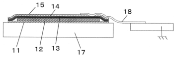
- Sectional drawing of the noise absorption heat conductive sheet in one embodiment of this indication Sectional view of electronic device using noise absorbing thermally conductive sheet in an embodiment of the present disclosure
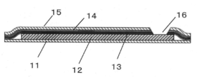
- Sectional drawing of another noise absorption heat conductive sheet in one embodiment of this indication Sectional drawing of the noise absorption heat conductive sheet in one embodiment of this indication
- FIG. 1 is a cross-sectional view of a noise absorbing thermally conductive sheet according to an embodiment of the present disclosure.
- the graphite sheet 12 is bonded to the main surface (upper surface) of the first double-sided tape 11, and the second double-sided tape 13 is further bonded onto the graphite sheet 12,
- the metal layer 14 is provided on the tape 13, and the protective film 15 is provided on the metal layer 14. More specifically, the back surface of the graphite sheet 12 is disposed to face the main surface of the first double-sided tape 11.
- the back surface of the second double-sided tape 13 is disposed on the main surface of the graphite sheet 12 so as to face each other.
- the metal layer 14 is provided on the main surface of the second double-sided tape 13, and the protective film 15 is provided on the metal layer 14.
- the first double-sided adhesive tape 11 one in which an acrylic adhesive (not shown) having a thickness of about 3 ⁇ m is provided on both sides of a polyethylene terephthalate (hereinafter referred to as PET) having a thickness of about 6 ⁇ m.
- the graphite sheet 12 is a pyrolytic graphite sheet having a thickness of about 25 ⁇ m, and the first double-sided tape 11 and the graphite sheet 12 are bonded together by an adhesive provided on the first double-sided tape 11.
- the second double-sided tape 13 uses a conductive material obtained by applying an adhesive material mixed with conductive particles on both sides of a metal foil.
- a material of metal foil aluminum is mentioned, for example.
- metals such as copper, gold, silver and alloys such as AlTi can be cited as materials for the metal foil.
- aluminum was used as the material of the metal foil.
- conductive particles for example, metal powder can be mentioned.
- metal powder aluminum powder is mentioned, for example.
- Other examples of metal powder include copper powder and the like.
- the second double-sided tape 13 and the graphite sheet 12 are bonded to each other by an adhesive provided on the second double-sided tape 13.
- the first double-sided tape 11 and the second double-sided tape 13 have a shape larger than that of the graphite sheet 12 and the periphery of the graphite sheet 12 is bonded with the first double-sided tape 11 and the second double-sided tape 13 Is desirable.
- the graphite sheet 12 can be completely covered, and it is possible to prevent the powder of graphite from coming out to the outside.
- a metal layer 14 and a protective film 15 are provided on the upper surface of the second double-sided tape 13.
- the protective film 15 is made of PET having a thickness of about 6 ⁇ m
- the metal layer 14 is a vapor deposited film of nickel having a thickness of about 0.02 ⁇ m sputter-deposited on one surface of the protective film 15 and further having a thickness of about 1 ⁇ m thereon.
- the vapor deposition film of copper is provided.
- the adhesive film on the upper surface of the second double-sided tape 13 bonds the protective film 15 integrated with the metal layer 14.
- a through hole 16 is provided in a part of the protective film 15 so that the metal layer 14 can be seen from above.
- the through holes 16 can be formed, for example, by irradiating the protective film 15 with laser light and removing a part of the protective film 15. At this time, it is desirable that the through holes 16 be tapered so that the surface opposite to the surface on which the metal layer 14 is provided is wide. In this way, the metal layer 14 can be exposed even if part of the metal layer 14 is also removed.
- the second double-sided tape 13 may be insulating, it is preferable to use an adhesive material coated with a conductive particle mixed on both sides of the metal foil to provide conductivity. More desirable. By doing this, the metal layer 14 and the graphite sheet 12 can be electrically connected, and the shielding property can be improved. Furthermore, the heat transmitted to the graphite sheet 12 can be released to the ground through the conductive tape 18 shown in FIG. 2, and the heat dissipation can be improved.
- the through holes 16 may be formed in the middle of the protective film 15 and not only the one surrounded by the protective film 15 but also one in which the end of the protective film 15 is cut out.
- FIG. 2 is a cross-sectional view of an electronic device using the noise absorbing thermally conductive sheet.
- the back surface (lower surface) side of the first double-sided adhesive tape 11 of the noise absorbing thermally conductive sheet is attached to the upper surface of the heat generating component 17 mounted on the substrate, and the conductive tape 18 is attached to cover the through hole 16.
- the conductive tape 18 and the metal layer 14 are electrically connected, and the end of the conductive tape 18 is connected to ground, whereby the metal layer 14 can be connected to ground.
- the heat generated from the heat generating component 17 is diffused to the whole by the graphite sheet 12.
- the noise coming from the outside can be shielded by the ground-connected metal layer 14 and the influence of the noise can be reduced with respect to the heat-generating component 17 and the electronic components arranged therearound.
- FIG. 3 is a cross-sectional view of another noise absorbing thermally conductive sheet in an embodiment of the present invention.
- the configuration is similar to that of the noise absorbing thermally conductive sheet of FIG. 1 except that the second double-sided tape 13 is insulating.
- the through holes 16 are formed to reach the graphite sheet 12.
- the graphite sheet 12 and the metal layer 14 are conducted to each other, the graphite sheet 12 and the metal layer 14 are connected to ground by sticking the conductive tape 18 so as to cover the through holes 16. And the shielding can be improved. Furthermore, the heat transmitted to the graphite sheet 12 can be dissipated to the ground through the conductive tape 18, and the heat dissipation can be improved.
- the through hole 16 be tapered so that the surface opposite to the surface on which the metal layer 14 is provided is wide.
- the conductive tape 18 can be electrically connected to the metal layer 14 and the graphite sheet 12 reliably.
- the first double-sided tape 11 may be conductive, it is desirable that the first double-sided tape 11 be insulating. In this way, a short circuit or the like on the substrate or an electronic component can be prevented while having thermal conductivity, and a highly reliable electronic device can be obtained.
- the noise absorbing thermally conductive sheet according to the present disclosure can obtain a noise absorbing thermally conductive sheet excellent in thermal conductivity and shielding ability even if thin and an electronic device using the same, and is industrially useful.
- first double-sided tape 12 graphite sheet 13 second double-sided tape 14 metal layer 15 protective film 16 through hole 17 heat-generating component 18 conductive tape
Landscapes
- Engineering & Computer Science (AREA)
- Microelectronics & Electronic Packaging (AREA)
- Physics & Mathematics (AREA)
- Thermal Sciences (AREA)
- Cooling Or The Like Of Semiconductors Or Solid State Devices (AREA)
- Cooling Or The Like Of Electrical Apparatus (AREA)
Abstract
薄くても熱伝導性およびシールド性に優れたノイズ吸収熱伝導シートを提供するとともに、これを用いた電子機器提供する。第1の両面テープ(11)の一面にグラファイトシート(12)を設け、グラファイトシート(12)の上に第2の両面テープ(13)を設け、第2の両面テープ(13)の上に金属層(14)を設け、金属層(14)の上に保護フィルム(15)を設け、保護フィルム(15)の一部に貫通孔(16)が設けられたものである。この貫通孔(16)を通して金属層(14)をグランド接続することができ、シールド性を向上させることができる。
Description
本開示は、各種電子機器に用いられるノイズ吸収熱伝導シートおよびこれを用いた電子機器に関するものである。
近年電子機器の各種機能や処理能力等が急速に向上し、それに伴い半導体素子をはじめとする電子部品からの発熱量は増加する傾向にある。また外部から入るあるいは内部で発生するノイズに対する対策も求められている。このため半導体素子等の動作特性や信頼性等を保つために熱伝導体を用いて発熱体からヒートシンク等に熱を伝達させる、あるいはシールド等の対策が行なわれている。そのため、熱伝導体として面方向の熱伝導性に優れたグラファイトシートを用い、電磁波吸収層と組み合わせることにより、両方の効果を得ることが行なわれている。
なお、この出願の発明に関連する先行技術文献情報としては、例えば、特許文献1が知られている。
しかしながら電波吸収層として電波吸収材と樹脂の混合物を用いると、厚さが厚くなり、またその効果も十分なものではなかった。
上記課題を解決するために、本開示にかかるノイズ吸収熱伝導シートは、主面と裏面とを有する第1の両面テープと、主面と裏面とを有するグラファイトシートと、主面と裏面とを有する第2の両面テープと、金属層と、保護フィルムと、を有する。グラファイトシートは、第1の両面テープの上に、第1の両面テープの主面とグラファイトシートの裏面とが対向するように配置されている。第2の両面テープは、グラファイトシートの上に、グラファイトシートの主面と第2の両面テープの裏面とが対向するように配置されている。金属層および保護フィルムは、第2の両面テープの主面上に順次配置されている。また、保護フィルムの一部に貫通孔が設けられている。
また、本開示の電子機器は、上面を有する発熱部品と、上記ノイズ吸収熱伝導シートと、導電性テープとを備える。ノイズ吸収熱伝導シートは、発熱部品の上に、発熱部品の上面が第1の両面テープの裏面に接するように配置されている。導電性テープは、ノイズ吸収熱伝導シートの上に、貫通孔を覆うように配置されている。また、導電性テープは接地されている。
このようにすることにより、薄くても熱伝導に優れたノイズ吸収熱伝導シートを得ることができる。さらに貫通孔を覆うようにグランド接続された導電性テープを貼り合せ、導電性テープと金属層とで電気的に接続することにより、シールド性をさらに向上させることができる。
以下、本開示の一実施の形態におけるノイズ吸収熱伝導シートについて、図面を参照しながら説明する。
図1は本開示の一実施の形態におけるノイズ吸収熱伝導シートの断面図である。このノイズ吸収熱伝導シートは、第1の両面テープ11の主面(上面)にグラファイトシート12を貼り合せ、さらにこのグラファイトシート12の上に第2の両面テープ13を貼り合せ、第2の両面テープ13の上に金属層14を設け、金属層14の上に保護フィルム15を設けたものである。より具体的には、第1の両面テープ11の主面にグラファイトシート12の裏面が向かい合うように配置されている。グラファイトシート12の主面に第2の両面テープ13の裏面が向かい合うように配置されている。第2の両面テープ13の主面上に金属層14が設けられ、金属層14の上に保護フィルム15が設けられている。
ここで第1の両面テープ11は、厚さ約6μmのポリエチレンテレフタレート(以下PETと記す)の両面に厚さ約3μmのアクリル系粘着材(図示せず)を設けたものを用いている。グラファイトシート12は、厚さ約25μmの熱分解グラファイトシートを用い、第1の両面テープ11とグラファイトシート12とは、第1の両面テープ11に設けられた粘着材により貼り合わされている。
第2の両面テープ13は、金属箔の両面に、導電性粒子を混ぜた粘着材を塗布して導電性をもたせたものを用いている。ここで、金属箔の材料として、例えばアルミニウムがあげられる。金属箔の材料としてアルミニウム以外に、銅、金、銀などの金属や、AlTi等の合金があげられる。本実施形態においては、金属箔の材料として、アルミニウムを用いた。また、導電性粒子としては、例えば金属粉があげられる。金属粉としては、例えばアルミニウム粉があげられる。金属粉として、他に銅粉等があげられる。
第2の両面テープ13とグラファイトシート12とは、第2の両面テープ13に設けられた粘着材により貼り合わされている。ここで第1の両面テープ11および第2の両面テープ13を、グラファイトシート12よりも大きな形状とし、グラファイトシート12の周辺を第1の両面テープ11と第2の両面テープ13とで貼り合せることが望ましい。このようにすることで、グラファイトシート12を完全に覆うことができ、外部にグラファイトの粉が出ることを防ぐことができる。
さらに第2の両面テープ13の上面には、金属層14、保護フィルム15が設けられている。この保護フィルム15は、厚さ約6μmのPETからなり、金属層14はこの保護フィルム15の一面にスパッタ蒸着された厚さ約0.02μmのニッケルの蒸着膜、さらにその上に厚さ約1μmの銅の蒸着膜を設けたものである。第2の両面テープ13の上面の粘着材により、金属層14と一体になった保護フィルム15が貼り合わされている。
保護フィルム15の一部に貫通孔16が設けられ、上から金属層14が見えるようになっている。この貫通孔16は例えば保護フィルム15にレーザ光を照射し、保護フィルム15の一部を除去することにより形成することができる。このとき貫通孔16は金属層14を設けた面とは反対側の面が広くなるように、テーパ状に設けることが望ましい。このようにすることにより、もし金属層14の一部も除去された場合でも、金属層14を露出させることができる。
なお、第2の両面テープ13は、絶縁性のものであってもかまわないが、金属箔の両面に、導電性粒子を混ぜた粘着材を塗布して導電性をもたせたものを用いることがより望ましい。このようにすることにより、金属層14とグラファイトシート12を電気的に接続することができ、シールド性を向上させることができる。さらにグラファイトシート12に伝わった熱を、図2に示す導電性テープ18を通じてグランドにも逃がすことができ、放熱性を向上させることができる。
なおこの貫通孔16は保護フィルム15の中ほどに形成され、周囲を保護フィルム15で囲まれたものだけでなく、保護フィルム15の端部を切り欠いたものであっても良い。
図2は上記ノイズ吸収熱伝導シートを用いた電子機器の断面図である。上記ノイズ吸収熱伝導シートの第1の両面テープ11の裏面(下面)側を、基板に実装された発熱部品17の上面に貼り合せ、貫通孔16を覆うように導電性テープ18を貼る。そして、導電性テープ18と金属層14を電気的に接続し、導電性テープ18の端部をグランド接続することにより金属層14をグランド接続することができる。このように構成することにより発熱部品17から発生する熱はグラファイトシート12により全体に拡散される。それとともに、外部から来るノイズはグランド接続された金属層14によりシールドすることができ、発熱部品17およびその周辺に配置された電子部品に対して、ノイズの影響を低減することができる。
図3は本発明の一実施の形態における別のノイズ吸収熱伝導シートの断面図である。構成は図1のノイズ吸収熱伝導シートと同様であるが、第2の両面テープ13が絶縁性であることが異なっている。
貫通孔16はグラファイトシート12にまで達するように形成されている。このようにすることにより、グラファイトシート12、金属層14がお互いに導通しているため、貫通孔16を覆うように導電性テープ18を貼ることにより、グラファイトシート12および金属層14をグランド接続することができ、シールド性を向上させることができる。さらにグラファイトシート12に伝わった熱を、導電性テープ18を通じてグランドにも逃がすことができ、放熱性を向上させることができる。
貫通孔16は金属層14を設けた面とは反対側の面が広くなるように、テーパ状に設けることが望ましい。このようにすることにより、導電性テープ18と金属層14およびグラファイトシート12を確実に電気的に接続することができる。
なお第1の両面テープ11は導電性であることもありうるが、絶縁性とすることが望ましい。このようにすることにより、熱伝導性を有しながら、基板上あるいは電子部品のショート等を防ぐことができ、信頼性の高い電子機器を得ることができる。
本開示に係るノイズ吸収熱伝導シートは、薄くても熱伝導性およびシールド性に優れたノイズ吸収熱伝導シートおよびこれを用いた電子機器を得ることができ、産業上有用である。
11 第1の両面テープ
12 グラファイトシート
13 第2の両面テープ
14 金属層
15 保護フィルム
16 貫通孔
17 発熱部品
18 導電性テープ
12 グラファイトシート
13 第2の両面テープ
14 金属層
15 保護フィルム
16 貫通孔
17 発熱部品
18 導電性テープ
Claims (6)
- 主面と裏面とを有する第1の両面テープと、
主面と裏面とを有するグラファイトシートと、
主面と裏面とを有する第2の両面テープと、
金属層と、
保護フィルムと、を有し、
前記グラファイトシートは、前記第1の両面テープの前記主面と前記グラファイトシートの前記裏面とが対向するように、前記第1の両面テープの前記主面上に配置され、
前記第2の両面テープは、前記グラファイトシートの前記主面と前記第2の両面テープの前記裏面とが対向するように、前記グラファイトシートの上に配置され、
前記金属層および前記保護フィルムは、前記第2の両面テープの前記主面の上に順次配置され、
前記保護フィルムの一部に貫通孔が設けられている、ノイズ吸収熱伝導シート。 - 前記金属層は、前記保護フィルムの一面に設けられた蒸着膜である、請求項1記載のノイズ吸収熱伝導シート。
- 前記金属層は少なくとも銅を含む、請求項1記載のノイズ吸収熱伝導シート。
- 前記第2の両面テープは、導電性を有する、請求項1記載のノイズ吸収熱伝導シート。
- 前記貫通孔は、前記保護フィルムから前記グラファイトシートに達するまで貫通している、請求項1記載のノイズ吸収熱伝導シート。
- 上面を有する発熱部品と、請求項1記載のノイズ吸収熱伝導シートと、導電性テープとを備え、
前記ノイズ吸収熱伝導シートは、前記発熱部品の上に、前記発熱部品の前記上面が前記第1の両面テープの前記裏面に接するように配置され、
前記導電性テープは、前記ノイズ吸収熱伝導シートの上に、前記貫通孔を覆うように配置され、
前記導電性テープは接地されている、電子機器。
Applications Claiming Priority (2)
| Application Number | Priority Date | Filing Date | Title |
|---|---|---|---|
| JP2017-249756 | 2017-12-26 | ||
| JP2017249756 | 2017-12-26 |
Publications (1)
| Publication Number | Publication Date |
|---|---|
| WO2019130995A1 true WO2019130995A1 (ja) | 2019-07-04 |
Family
ID=67063050
Family Applications (1)
| Application Number | Title | Priority Date | Filing Date |
|---|---|---|---|
| PCT/JP2018/044331 Ceased WO2019130995A1 (ja) | 2017-12-26 | 2018-12-03 | ノイズ吸収熱伝導シートおよびこれを用いた電子機器 |
Country Status (1)
| Country | Link |
|---|---|
| WO (1) | WO2019130995A1 (ja) |
Cited By (2)
| Publication number | Priority date | Publication date | Assignee | Title |
|---|---|---|---|---|
| JP2022115093A (ja) * | 2021-01-27 | 2022-08-08 | 河南▲き▼力新材料科技有限公司 | 熱伝導構造及び電子装置 |
| JP2022115094A (ja) * | 2021-01-27 | 2022-08-08 | 河南▲き▼力新材料科技有限公司 | 熱伝導構造及び電子装置 |
Citations (5)
| Publication number | Priority date | Publication date | Assignee | Title |
|---|---|---|---|---|
| JPH10330177A (ja) * | 1997-05-30 | 1998-12-15 | Matsushita Electric Ind Co Ltd | 金属−グラファイト複合体及びそれを用いた放熱体 |
| JP2009280433A (ja) * | 2008-05-21 | 2009-12-03 | Kaneka Corp | グラファイト複合フィルム |
| WO2014045671A1 (ja) * | 2012-09-21 | 2014-03-27 | 株式会社村田製作所 | 電子機器 |
| JP2015216184A (ja) * | 2014-05-09 | 2015-12-03 | パナソニックIpマネジメント株式会社 | 熱輸送シートおよびこれを用いた放熱構造 |
| WO2017022221A1 (ja) * | 2015-08-05 | 2017-02-09 | パナソニックIpマネジメント株式会社 | 放熱構造および電子機器 |
-
2018
- 2018-12-03 WO PCT/JP2018/044331 patent/WO2019130995A1/ja not_active Ceased
Patent Citations (5)
| Publication number | Priority date | Publication date | Assignee | Title |
|---|---|---|---|---|
| JPH10330177A (ja) * | 1997-05-30 | 1998-12-15 | Matsushita Electric Ind Co Ltd | 金属−グラファイト複合体及びそれを用いた放熱体 |
| JP2009280433A (ja) * | 2008-05-21 | 2009-12-03 | Kaneka Corp | グラファイト複合フィルム |
| WO2014045671A1 (ja) * | 2012-09-21 | 2014-03-27 | 株式会社村田製作所 | 電子機器 |
| JP2015216184A (ja) * | 2014-05-09 | 2015-12-03 | パナソニックIpマネジメント株式会社 | 熱輸送シートおよびこれを用いた放熱構造 |
| WO2017022221A1 (ja) * | 2015-08-05 | 2017-02-09 | パナソニックIpマネジメント株式会社 | 放熱構造および電子機器 |
Cited By (4)
| Publication number | Priority date | Publication date | Assignee | Title |
|---|---|---|---|---|
| JP2022115093A (ja) * | 2021-01-27 | 2022-08-08 | 河南▲き▼力新材料科技有限公司 | 熱伝導構造及び電子装置 |
| JP2022115094A (ja) * | 2021-01-27 | 2022-08-08 | 河南▲き▼力新材料科技有限公司 | 熱伝導構造及び電子装置 |
| JP7288102B2 (ja) | 2021-01-27 | 2023-06-06 | 河南▲き▼力新材料科技有限公司 | 熱伝導構造及び電子装置 |
| JP7288101B2 (ja) | 2021-01-27 | 2023-06-06 | 河南▲き▼力新材料科技有限公司 | 熱伝導構造及び電子装置 |
Similar Documents
| Publication | Publication Date | Title |
|---|---|---|
| US10952310B2 (en) | High-frequency module | |
| US6131651A (en) | Flexible heat transfer device and method | |
| US9510452B2 (en) | Electromagnetic shielding member and electromagnetic shielding structure | |
| JP6676191B2 (ja) | 半導体装置 | |
| WO2018159453A1 (ja) | モジュール | |
| JP2012191002A (ja) | 半導体装置 | |
| WO2019130995A1 (ja) | ノイズ吸収熱伝導シートおよびこれを用いた電子機器 | |
| US7943435B2 (en) | Underfill film having thermally conductive sheet | |
| KR20200141321A (ko) | 방열 칩 온 필름 패키지 | |
| JP2020025002A (ja) | 電子装置及び電子装置の製造方法 | |
| JP3164067U (ja) | 回路板 | |
| JP2005101365A (ja) | 電子装置 | |
| TW201927084A (zh) | 軟性線路板結構 | |
| WO2020095733A1 (ja) | 抵抗器 | |
| US7355276B1 (en) | Thermally-enhanced circuit assembly | |
| CN112888238B (zh) | 散热架构 | |
| JPH10117084A (ja) | 電磁波吸収体 | |
| JP2019153611A (ja) | モジュール | |
| KR20230130414A (ko) | Mid와 mdm을 적용한 열전도 패드가 구비된 전자기기 및 그 제조방법 | |
| JPH0430491A (ja) | 複合基板 | |
| WO2019130996A1 (ja) | 熱伝導シートおよびこれを用いた放熱体 | |
| JP2001053202A (ja) | 電子部品用ヒートシンク | |
| TWM461036U (zh) | 散熱外殼 | |
| KR102071921B1 (ko) | 높은 방열 성능을 갖는 방열 프레임 | |
| KR20240001922A (ko) | Cigarette Filter(CF)를 이용한 전자파 차폐 특성을 갖는 방열 시트 |
Legal Events
| Date | Code | Title | Description |
|---|---|---|---|
| 121 | Ep: the epo has been informed by wipo that ep was designated in this application |
Ref document number: 18894510 Country of ref document: EP Kind code of ref document: A1 |
|
| NENP | Non-entry into the national phase |
Ref country code: DE |
|
| 122 | Ep: pct application non-entry in european phase |
Ref document number: 18894510 Country of ref document: EP Kind code of ref document: A1 |
|
| NENP | Non-entry into the national phase |
Ref country code: JP |