WO2019130865A1 - 投影制御装置、ヘッドアップディスプレイ装置、投影制御方法およびプログラム - Google Patents
投影制御装置、ヘッドアップディスプレイ装置、投影制御方法およびプログラム Download PDFInfo
- Publication number
- WO2019130865A1 WO2019130865A1 PCT/JP2018/041966 JP2018041966W WO2019130865A1 WO 2019130865 A1 WO2019130865 A1 WO 2019130865A1 JP 2018041966 W JP2018041966 W JP 2018041966W WO 2019130865 A1 WO2019130865 A1 WO 2019130865A1
- Authority
- WO
- WIPO (PCT)
- Prior art keywords
- image
- viewer
- projection control
- virtual image
- unit
- Prior art date
- Legal status (The legal status is an assumption and is not a legal conclusion. Google has not performed a legal analysis and makes no representation as to the accuracy of the status listed.)
- Ceased
Links
Images







Classifications
-
- A—HUMAN NECESSITIES
- A61—MEDICAL OR VETERINARY SCIENCE; HYGIENE
- A61B—DIAGNOSIS; SURGERY; IDENTIFICATION
- A61B5/00—Measuring for diagnostic purposes; Identification of persons
- A61B5/16—Devices for psychotechnics; Testing reaction times ; Devices for evaluating the psychological state
-
- B—PERFORMING OPERATIONS; TRANSPORTING
- B60—VEHICLES IN GENERAL
- B60K—ARRANGEMENT OR MOUNTING OF PROPULSION UNITS OR OF TRANSMISSIONS IN VEHICLES; ARRANGEMENT OR MOUNTING OF PLURAL DIVERSE PRIME-MOVERS IN VEHICLES; AUXILIARY DRIVES FOR VEHICLES; INSTRUMENTATION OR DASHBOARDS FOR VEHICLES; ARRANGEMENTS IN CONNECTION WITH COOLING, AIR INTAKE, GAS EXHAUST OR FUEL SUPPLY OF PROPULSION UNITS IN VEHICLES
- B60K35/00—Instruments specially adapted for vehicles; Arrangement of instruments in or on vehicles
- B60K35/10—Input arrangements, i.e. from user to vehicle, associated with vehicle functions or specially adapted therefor
-
- B—PERFORMING OPERATIONS; TRANSPORTING
- B60—VEHICLES IN GENERAL
- B60K—ARRANGEMENT OR MOUNTING OF PROPULSION UNITS OR OF TRANSMISSIONS IN VEHICLES; ARRANGEMENT OR MOUNTING OF PLURAL DIVERSE PRIME-MOVERS IN VEHICLES; AUXILIARY DRIVES FOR VEHICLES; INSTRUMENTATION OR DASHBOARDS FOR VEHICLES; ARRANGEMENTS IN CONNECTION WITH COOLING, AIR INTAKE, GAS EXHAUST OR FUEL SUPPLY OF PROPULSION UNITS IN VEHICLES
- B60K35/00—Instruments specially adapted for vehicles; Arrangement of instruments in or on vehicles
- B60K35/20—Output arrangements, i.e. from vehicle to user, associated with vehicle functions or specially adapted therefor
- B60K35/21—Output arrangements, i.e. from vehicle to user, associated with vehicle functions or specially adapted therefor using visual output, e.g. blinking lights or matrix displays
- B60K35/23—Head-up displays [HUD]
- B60K35/233—Head-up displays [HUD] controlling the size or position in display areas of virtual images depending on the condition of the vehicle or the driver
-
- B—PERFORMING OPERATIONS; TRANSPORTING
- B60—VEHICLES IN GENERAL
- B60K—ARRANGEMENT OR MOUNTING OF PROPULSION UNITS OR OF TRANSMISSIONS IN VEHICLES; ARRANGEMENT OR MOUNTING OF PLURAL DIVERSE PRIME-MOVERS IN VEHICLES; AUXILIARY DRIVES FOR VEHICLES; INSTRUMENTATION OR DASHBOARDS FOR VEHICLES; ARRANGEMENTS IN CONNECTION WITH COOLING, AIR INTAKE, GAS EXHAUST OR FUEL SUPPLY OF PROPULSION UNITS IN VEHICLES
- B60K35/00—Instruments specially adapted for vehicles; Arrangement of instruments in or on vehicles
- B60K35/20—Output arrangements, i.e. from vehicle to user, associated with vehicle functions or specially adapted therefor
- B60K35/21—Output arrangements, i.e. from vehicle to user, associated with vehicle functions or specially adapted therefor using visual output, e.g. blinking lights or matrix displays
- B60K35/23—Head-up displays [HUD]
- B60K35/235—Head-up displays [HUD] with means for detecting the driver's gaze direction or eye points
-
- B—PERFORMING OPERATIONS; TRANSPORTING
- B60—VEHICLES IN GENERAL
- B60K—ARRANGEMENT OR MOUNTING OF PROPULSION UNITS OR OF TRANSMISSIONS IN VEHICLES; ARRANGEMENT OR MOUNTING OF PLURAL DIVERSE PRIME-MOVERS IN VEHICLES; AUXILIARY DRIVES FOR VEHICLES; INSTRUMENTATION OR DASHBOARDS FOR VEHICLES; ARRANGEMENTS IN CONNECTION WITH COOLING, AIR INTAKE, GAS EXHAUST OR FUEL SUPPLY OF PROPULSION UNITS IN VEHICLES
- B60K35/00—Instruments specially adapted for vehicles; Arrangement of instruments in or on vehicles
- B60K35/20—Output arrangements, i.e. from vehicle to user, associated with vehicle functions or specially adapted therefor
- B60K35/28—Output arrangements, i.e. from vehicle to user, associated with vehicle functions or specially adapted therefor characterised by the type of the output information, e.g. video entertainment or vehicle dynamics information; characterised by the purpose of the output information, e.g. for attracting the attention of the driver
-
- G—PHYSICS
- G02—OPTICS
- G02B—OPTICAL ELEMENTS, SYSTEMS OR APPARATUS
- G02B27/00—Optical systems or apparatus not provided for by any of the groups G02B1/00 - G02B26/00, G02B30/00
- G02B27/01—Head-up displays
-
- G—PHYSICS
- G09—EDUCATION; CRYPTOGRAPHY; DISPLAY; ADVERTISING; SEALS
- G09G—ARRANGEMENTS OR CIRCUITS FOR CONTROL OF INDICATING DEVICES USING STATIC MEANS TO PRESENT VARIABLE INFORMATION
- G09G3/00—Control arrangements or circuits, of interest only in connection with visual indicators other than cathode-ray tubes
- G09G3/20—Control arrangements or circuits, of interest only in connection with visual indicators other than cathode-ray tubes for presentation of an assembly of a number of characters, e.g. a page, by composing the assembly by combination of individual elements arranged in a matrix no fixed position being assigned to or needed to be assigned to the individual characters or partial characters
-
- A—HUMAN NECESSITIES
- A61—MEDICAL OR VETERINARY SCIENCE; HYGIENE
- A61B—DIAGNOSIS; SURGERY; IDENTIFICATION
- A61B5/00—Measuring for diagnostic purposes; Identification of persons
- A61B5/103—Measuring devices for testing the shape, pattern, colour, size or movement of the body or parts thereof, for diagnostic purposes
- A61B5/107—Measuring physical dimensions, e.g. size of the entire body or parts thereof
Definitions
- the present invention relates to a projection control device, a head-up display device, a projection control method, and a program.
- a head-up display device which projects information provided to the driver, such as route guidance information or speed information, as a virtual image in front of the driver's line of sight.
- information provided to the driver such as route guidance information or speed information
- the viewer in order for the viewer to view the virtual image correctly, the viewer needs to be in the correct posture with respect to the display position of the virtual image.
- a technology for moving a screen to be moved by moving the sight line and pointing direction to a desired position by making the sight line and pointing direction move on the display screen to be moved for example, see Patent Document 1).
- a technology is known that includes a combiner, an infrared light illumination device, and an image sensor for capturing an image of the driver's face illuminated by the infrared light, and detects the driver's line of sight and face direction (for example, Patent Document 2) reference).
- the head-up display device it is preferable to accurately detect the head position as the posture of the viewer from the relative positional relationship of the pupil position of the viewer with respect to the virtual image.
- the present invention has been made in view of the above, and an object thereof is to accurately detect the position of the head of the viewer from the relative positional relationship between the position of the pupil of the viewer and the virtual image.
- a projection control device controls a projection control unit that controls projection of a display image so that a virtual image is viewed in front of the viewer;
- a posture when the viewer visually recognizes the virtual image based on a relative positional relationship between a video data acquisition unit that acquires a photographed image photographed by a photographing unit capable of photographing and a pupil position of the viewer with respect to the virtual image The projection control unit controls the projection of the reference position determination image to be projected toward the viewer, and the detection unit is acquired by the image data acquisition unit.
- a head-up display device includes the above-described projection control device, and at least one of a projection unit and the photographing unit.
- a projection control step of controlling projection of a display video so that a virtual image is viewed in front of a viewer, and a video for obtaining a captured video captured by a capturing unit capable of capturing a viewer The projection control step including a data acquisition step, and a detection step of detecting a posture when the viewer visually recognizes the virtual image based on a relative positional relationship of the viewer's pupil position with respect to the virtual image.
- a program according to the present invention includes a projection control step of controlling projection of a display image so that a virtual image is viewed in front of a viewer, and acquisition of image data for acquiring a captured image captured by a capturing unit capable of capturing a viewer.
- the projection control step includes The projection of the reference position determination video to be projected toward the viewer is controlled, and the detection step is an image obtained by capturing the reference position determination video projected by the viewer, acquired in the video data acquisition step It is projected that, from the image, the posture at which the viewer visually recognizes the virtual image, based on the relative positional relationship of the pupil position of the viewer to the virtual image. It is executed by a computer that operates as a control device.
- the present invention it is possible to accurately detect the head position of the viewer based on the relative positional relationship between the pupil position of the viewer and the virtual image.
- FIG. 1 is a block diagram showing a configuration example of a projection control apparatus for a vehicle according to the first embodiment.
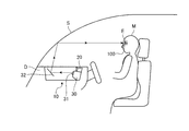
- FIG. 2 is a schematic view showing an example of the configuration of the head-up display device according to the first embodiment.
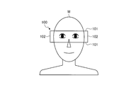
- FIG. 3 is a view showing an example of a reference position determination image displayed by the vehicle projection control device according to the first embodiment.
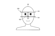
- FIG. 4 is a view showing another example of the reference position determination video image displayed by the vehicle projection control device according to the first embodiment.
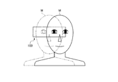
- FIG. 5 is a view showing an example of the pupil position of the driver detected by the vehicle projection control device according to the first embodiment.
- FIG. 6 is a view showing another example of the pupil position of the driver detected by the vehicle projection control device according to the first embodiment.
- FIG. 1 is a block diagram showing a configuration example of a projection control apparatus for a vehicle according to the first embodiment.
- FIG. 2 is a schematic view showing an example of the configuration of the head-up display device according to the first embodiment.
- FIG. 3 is a
- FIG. 7 is a view for explaining an example of a warning image generated by the projection control apparatus for a vehicle according to the first embodiment.
- FIG. 8 is a view for explaining another example of the warning image generated by the vehicle projection control device according to the first embodiment.
- FIG. 9 is a view for explaining an image projected by the vehicle projection control device according to the first embodiment.
- FIG. 10 is a flow chart showing the flow of processing in the projection control system for a vehicle according to the first embodiment.
- FIG. 11 is a block diagram showing a configuration example of a projection control apparatus for a vehicle according to a second embodiment.
- FIG. 12 is a view showing an example of the pupil position of the driver detected by the vehicle projection control device according to the second embodiment.
- FIG. 13 is a flowchart showing the flow of processing in the projection control system for a vehicle according to the second embodiment.
- FIG. 14 is a block diagram showing a configuration example of a projection control apparatus for a vehicle according to the third embodiment.
- FIG. 15 is a flowchart showing the flow of processing in the projection control system for a vehicle according to the third embodiment.
- HUD device head-up display device
- a projection control method a projection control method
- program a program according to the present invention
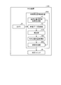
- FIG. 1 is a block diagram showing a configuration example of a projection control apparatus for a vehicle according to the first embodiment.
- FIG. 2 is a schematic view showing an example of the configuration of the head-up display device according to the first embodiment.
- the HUD device 10 projects a display image 200 including, for example, a route guidance image or a speed information image to cause a virtual image of the display image 200 to be viewed in front of the host vehicle.
- the HUD device 10 detects the pupil position of the driver M by projecting the image display light of the reference position determination image 100 onto the face of the driver M, thereby detecting the head position of the driver M ( Posture) can be detected.
- the posture of the driver M is the head position of the driver M or the posture of the head.
- the HUD device 10 has a camera 20, a projection unit 30, and a projection control device 40 for a vehicle.
- the camera 20, the projection unit 30, and the vehicle projection control device 40 are integrally disposed below the dashboard D of the vehicle.
- the camera 20 shoots the face of the driver M seated in the driver's seat. More specifically, the camera 20 projects the reference position determination video 100 projected toward the face of the driver M and projected onto the face of the driver M as captured video data. In other words, in the captured video data captured by the camera 20, the driver M's face and the reference position determination video 100 are displayed. The camera 20 outputs the captured video data to the video data acquisition unit 42 of the vehicle projection control device 40.
- the projection unit 30 projects the display image 200 or the reference position determination image 100.
- the projection unit 30 has a display unit 31, a concave mirror 32, and a reflection unit.
- the reflecting portion is a windshield S.
- the projection unit 30 reflects the image display light of the display image 200 on the windshield S to make the driver M visually recognize it as a virtual image.
- the projection unit 30 reflects the image display light of the reference position determination image 100 on the windshield S and projects the light on the face of the driver M.
- the projection unit 30 passes the same light path and projects the same projection position during normal use and posture detection.
- the display unit 31 is a display including, for example, a liquid crystal display (LCD: Liquid Crystal Display) or an organic EL (Organic Electro-Luminescence) display.
- LCD Liquid Crystal Display
- organic EL Organic Electro-Luminescence
- the display unit 31 displays the display image 200 on the display surface based on the video signal from the projection control unit (output control unit) 45 of the vehicle projection control device 40.
- the display unit 31 displays the reference position determination video 100 on the display surface based on the video signal from the projection control unit 45 of the vehicle projection control device 40 at the time of attitude detection.
- the image display light of the display image 200 or the reference position determination image 100 displayed on the display surface of the display unit 31 is incident on the concave mirror 32.
- the concave mirror 32 is disposed to face the display surface of the display unit 31 and the windshield S.
- the concave mirror 32 is convexly curved forward in the traveling direction of the vehicle.
- the concave mirror 32 reflects the image display light incident from the display surface of the display unit 31 toward the windshield S.
- the windshield S is disposed forward of the driver's seat in the direction of travel.
- the windshield S is convexly curved forward in the traveling direction of the vehicle.
- the windshield S reflects the image display light of the display image 200 incident from the concave mirror 32 and causes the driver M to recognize it as a virtual image.
- the windshield S reflects the image display light of the reference position determination image 100 incident from the concave mirror 32 and projects the reference position determination image 100 on the face of the driver M.
- the vehicle projection control device 40 controls the projection of the display image 200 or the reference position determination image 100 by the projection unit 30.
- the vehicle projection control device 40 is, for example, an arithmetic processing device configured by a CPU (Central Processing Unit) or the like.
- the vehicle projection control device 40 loads a program stored in a storage unit (not shown) into a memory and executes an instruction included in the program.
- the vehicle projection control device 40 has a reference position determination video generation unit 41, a video data acquisition unit 42, a detection unit 43, a warning video generation unit (warning information generation unit) 44, and a projection control unit 45.
- the vehicle projection control device 40 includes an internal memory (not shown), and the internal memory is used for temporary storage of data in the vehicle projection control device 40 and the like.
- the reference position determination video generating unit 41 generates the reference position determination video 100 projected by the projection unit 30 of the HUD device 10.
- the reference position determination video image 100 is a video image of a mark indicating a reference position used to detect the pupil position of the driver M when detecting the posture of the driver M.
- the reference position determination video image 100 is projected on the same position as the projection position of the display image 200 through the same optical path as the optical path of the image display light of the display image 200 in normal use.
- the reference position determination video 100 is a video having a higher luminance than the display video 200. More specifically, the reference position determination video image 100 has such brightness that the image display light is reflected by the windshield S and projected onto the face of the driver M.
- the reference position determination image 100 is an image used to detect the relative positional relationship of the pupil position of the driver M with respect to the virtual image of the display image 200. More specifically, the reference position determination video 100 detects at least one of the position in the vertical direction of the pupil position of the driver M and the position in the left and right direction and the front and rear direction with respect to the virtual image of the display image 200. It is a video to be used.
- the reference position determination video 100 includes at least one of a first reference position determination video 101 indicating the reference position in the vertical direction and a second reference position determination video 102 indicating the reference position in the horizontal direction.
- the reference position determination video 100 is, for example, in a frame shape or a linear shape.
- FIG. 3 is a view showing an example of a reference position determination image displayed by the vehicle projection control device according to the first embodiment.
- FIG. 4 is a view showing another example of the reference position determination video image displayed by the vehicle projection control device according to the first embodiment.
- the reference position determination video 100 may have a rectangular frame shape formed by the pair of first reference position determination video 101 and the pair of second reference position determination video 102.
- the reference position determination video 100 may have an E-shaped shape formed by a pair of first reference position determination video 101 and one second reference position determination video 102. .
- the video data acquisition unit 42 acquires captured video data output from the camera 20.
- the video data acquisition unit 42 outputs the acquired captured video data to the detection unit 43.
- the detection unit 43 performs image processing on the captured video data, and drives the head position when the driver M visually recognizes the virtual image based on the relative positional relationship of the driver M's pupil position with respect to the virtual image. Detected as the posture of the person M. More specifically, the detection unit 43 detects the pupil position of the driver M with respect to the virtual image of the display image 200 based on the pupil position of the driver M and the reference position determination image 100 in the captured image data. The posture is detected from the head position of M. Thus, the detection unit 43 detects the posture of the driver M with respect to the virtual image of the display image 200.
- FIG. 5 is a view showing an example of the pupil position of the driver detected by the vehicle projection control device according to the first embodiment.
- FIG. 6 is a view showing another example of the pupil position of the driver detected by the vehicle projection control device according to the first embodiment.
- FIG. 3 shows a state in which the pupil position of the driver M does not shift with respect to the reference position determination image 100, in other words, a correct posture (predetermined posture) in which the head position of the driver M is a predetermined position. It is in the state of taking. As shown in FIG.
- the detection unit 43 positions the pupil of the driver M within the threshold range from the middle part of the pair of first reference position determination video images 101.
- the driver M detects that the posture is the predetermined posture.
- the detection unit 43 does not position the pupil of the driver M within the threshold range from the middle portion of the pair of first reference position determination images 101, or the pupil of the driver M is determined as the second reference position.
- FIG. 4 shows a state in which the position of the pupil of the driver M does not deviate with respect to the reference position determination image 100.
- the detection unit 43 detects that the pupil of the driver M is within the threshold range from the middle part of the pair of first reference position determination video images 101.
- the second reference position determination image 102 is positioned in the threshold range from the middle part between the pupils of the driver M, the driver M is detected as being in the predetermined posture.
- the detection unit 43 does not position the pupil of the driver M within the threshold range from the middle portion of the pair of first reference position determination images 101 or within the threshold range from the middle portion between the pupils of the driver M When one second reference position determination video image 102 is not located, the driver M is detected as not being in the predetermined posture.
- the detection unit 43 detects that the driver M is in the predetermined posture with respect to the reference position determination video 100.
- the driver M takes a predetermined posture also for the virtual image of the display image 200 projected to the same position as the reference position determination image 100.
- FIG. 5 shows a state in which the driver M does not take a predetermined posture with respect to the reference position determination video 100.
- the detection unit 43 detects that the driver M is not in the predetermined posture because the pupil of the driver M is not located within the threshold range from the middle part of the pair of first reference position determination images 101.
- the driver M is not in the predetermined posture even for the virtual image of the display video 200 projected to the same position as the reference position determination video 100.
- the two-dot chain line indicates the head position and the pupil position of the driver M who is in the predetermined posture.
- FIG. 6 shows a state in which the driver M does not take a predetermined posture with respect to the reference position determination video 100.
- the detection unit 43 detects that the driver M is not in the predetermined posture because the pupil of the driver M is not positioned so as to overlap the central portion of the reference position determination image 100.
- the driver M is not in the predetermined posture even for the virtual image of the display video 200 projected to the same position as the reference position determination video 100.
- the two-dot chain line indicates the head position and the pupil position of the driver M who is in the predetermined posture.
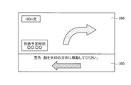
- the warning video generation unit 44 warns the driver M of a warning when the driver M does not have a predetermined posture for visually recognizing a virtual image based on the driver M's posture detected by the detector 43. As a warning video 300 is generated. More specifically, the warning video generation unit 44 generates a warning video 300 as warning information so as to be recognized as a virtual image in front.
- FIG. 7 is a view for explaining an example of a warning image generated by the projection control apparatus for a vehicle according to the first embodiment.
- FIG. 8 is a view for explaining another example of the warning image generated by the vehicle projection control device according to the first embodiment.
- FIG. 7 shows a case where the warning image 300 includes a character string notifying that the position of the face is shifted.
- FIG. 8 shows a case where the warning image 300 includes a character string instructing to set a predetermined posture, and a graphic indicating the moving direction by an arrow.
- the warning image 300 is superimposed and displayed on the lower portion of the display image 200 of the route guidance information.
- the projection control unit 45 controls the projection of the display image 200 so that the virtual image of the display image 200 is viewed in front of the host vehicle during normal use.
- the projection control unit 45 controls the projection of the reference position determination video 100 so as to project the image display light of the reference position determination video 100 on the face of the driver M at the time of posture detection.
- the projection control unit 45 controls projection so that the warning video 300 generated by the warning video generation unit 44 is viewed as a virtual image in the forward direction when the driver M does not have a predetermined posture for visual recognition of the virtual image. .
- the projection control unit 45 projects the display image 200, the reference position determination image 100, and the warning image 300 in the same optical path.
- the projection control unit 45 may control to project the reference position determination image 100 for one frame and to project the display image 200 for one frame in one second.
- FIG. 9 is a view for explaining an image projected by the vehicle projection control device according to the first embodiment. Since the reference position determination image 100 is projected for only one frame in one second, the driver M is not aware that the image display light of the reference position determination image 100 is projected on the driver M's face. , Position adjustment is possible. In the present embodiment, the projection control unit 45 projects the reference position determination video 100 only for one frame in one second.
- the projection control unit 45 may project the reference position determination video 100 as the posture detection time, for example, when the driver M executes the position adjustment start operation at the start of driving. In addition, the projection control unit 45 performs control so as to project the display image 200 as normal use while the driver M does not perform an operation.
- FIG. 10 is a flow chart showing the flow of processing in the projection control system for a vehicle according to the first embodiment.
- the vehicle projection control device 40 projects the reference position determination image 100 in one frame in one second, and displays the display image 200 in the remaining frames in one second. It explains as what is projected.
- the vehicle projection control device 40 determines whether it is the projection timing of the reference position determination video 100 (step ST11). More specifically, the vehicle projection control device 40 counts frames in one second to determine whether it is time to project the reference position determination video 100. If it is time to project the reference position determination video image 100 (Yes in step ST11), the vehicle projection control device 40 proceeds to step ST12. When it is not time to project the reference position determination video image 100 (No in step ST11), the vehicle projection control device 40 executes the process of step ST11 again.
- the vehicle projection control device 40 projects the reference position determination video 100 (step ST12). More specifically, the vehicle projection control device 40 causes the projection control unit 45 to output a control signal for projecting the reference position determination video 100 generated by the reference position determination video generation unit 41. The vehicle projection control device 40 proceeds to step ST13.
- the vehicle projection control device 40 captures an image by the camera 20 (step ST13). More specifically, the vehicle projection control device 40 captures the reference position determination video 100 projected on the face of the driver M by the camera 20 as captured video data. The vehicle projection control device 40 proceeds to step ST14.
- the vehicle projection control device 40 acquires photographed video data (step ST14). More specifically, the vehicle projection control device 40 causes the video data acquisition unit 42 to acquire captured video data captured by the camera 20. The vehicle projection control device 40 proceeds to step ST15.
- the vehicle projection control device 40 detects the pupil position (step ST15). More specifically, the vehicle projection control device 40 performs image processing on the captured video data by the detection unit 43 to detect the relative positional relationship between the reference position determination video 100 and the pupil of the driver M. Do. The vehicle projection control device 40 detects the displacement amount of the pupil position of the driver M by the detection unit 43. The vehicle projection control device 40 proceeds to step ST16.
- the vehicle projection control device 40 determines whether the posture of the driver M is a predetermined posture (step ST16). More specifically, when the amount of vertical or horizontal displacement of the pupil position of the driver M detected by the detection unit 43 is greater than or equal to the threshold value, the vehicle projection control device 40 does not have the posture of the driver M as the predetermined posture. It determines with (YES in step ST16), and proceeds to step ST17. When the amount of vertical or horizontal displacement of the pupil position of the driver M detected by the detection unit 43 is not equal to or greater than the threshold, the vehicle projection control device 40 determines that the posture of the driver M is the predetermined posture. (No in step ST16), the process proceeds to step ST19.
- step ST16 When it is determined that the posture of the driver M is not the predetermined posture (Yes in step ST16), the vehicle projection control device 40 generates a warning video 300 by the warning video generation unit 44 (step ST17). The vehicle projection control device 40 proceeds to step ST18.
- the vehicle projection control device 40 projects the warning image 300 (step ST18).
- the vehicle projection control device 40 causes the projection control unit 45 to output a control signal for projecting the warning video 300 acquired by the warning video generation unit 44 together with the display video 200.
- the vehicle projection control device 40 proceeds to step ST19.
- the vehicle projection control device 40 determines whether or not there is an end trigger (step ST19).
- the end trigger is, for example, a case where a button for ending the operation of the HUD device 10 is pressed or the vehicle is stopped and the engine is stopped.
- the vehicle projection control device 40 ends the process.
- the vehicle projection control device 40 executes the process of step ST11 again.
- the projection control device 40 for a vehicle projects the image display light of the reference position determination image 100 onto the face of the driver M, thereby setting the head position as the posture for the virtual image from the pupil position of the driver M. To detect. Then, the vehicle projection control device 40 projects the warning image 300 when the driver M deviates from the appropriate predetermined posture.
- the relative position between the reference position determination video 100 and the pupil of the driver M is projected by projecting the image display light of the reference position determination video 100 onto the face of the driver M. Detect relationships
- the present embodiment can detect the head position as the posture of the driver M with respect to the virtual image.
- the warning image 300 is sent to the driver M.
- the driver M recognizes that the driver M's posture deviates from an appropriate predetermined posture.
- the virtual image can be appropriately viewed by the driver M.
- the reference position determination video 100 is projected only for one frame in one second. Accordingly, in the present embodiment, the head of the driver M as the posture of the driver M with respect to the virtual image is made without the driver M being aware that the image display light of the reference position determination image 100 is projected on the driver M's face. The position can be detected.
- the image display light of the reference position determination image 100 is projected at the same position as the projection position of the display image 200 through the same optical path as the light path of the image display light of the display image 200 during normal use.
- the head position can be detected directly as the posture of the driver M with respect to the virtual image by projecting the image display light of the reference position determination image 100 onto the face of the driver M. it can.
- the camera 20, the projection unit 30, and the vehicle projection control device 40 are integrally disposed below the dashboard D of the vehicle.
- the apparatus for projecting the virtual image of the display image 200 during normal use can detect the head position as the posture of the driver M with respect to the virtual image.
- FIG. 11 is a block diagram showing a configuration example of a projection control apparatus for a vehicle according to a second embodiment.
- FIG. 12 is a view showing an example of the pupil position of the driver detected by the vehicle projection control device according to the second embodiment.
- FIG. 13 is a flowchart showing the flow of processing in the projection control system for a vehicle according to the second embodiment.
- the basic configuration of the HUD device 10A is the same as that of the HUD device 10 of the first embodiment.
- symbol is attached
- the HUD device 10A is different from that of the first embodiment in that the point having the size adjustment amount acquisition unit 46A and the processing in the detection unit 43A and the projection control unit 45A.
- the detection unit 43A detects a deviation in the front-rear direction of the pupil position of the driver M with respect to the virtual image of the display image 200 based on the pupil position of the driver M and the reference position determination video 100 in captured video data. More specifically, the detection unit 43A performs image processing on the captured video data, and when the thickness of a line included in the reference position determination video 100 is a thickness outside the threshold range, the virtual image of the display video 200 is generated. It is detected that the pupil position of the driver M has a deviation in the front-rear direction and is not a predetermined posture. As shown in FIG.
- the detection unit 43A shifts the pupil position of the driver M backward with respect to the virtual image of the display video 200. And detects that it is not in the predetermined posture.
- the detection unit 43A shifts the pupil position of the driver M with respect to the virtual image of the display image 200 in the forward direction and does not have a predetermined posture. To detect.
- the size adjustment amount acquisition unit 46A acquires the adjustment amount of the size of the virtual image projected forward based on the posture of the driver M detected by the detection unit 43A. More specifically, the size adjustment amount acquisition unit 46A causes the virtual image of the same size as the virtual image visually recognized in the predetermined posture to be visually recognized when the pupil position of the driver M has a shift in the forward direction and is not the predetermined posture. , To obtain the adjustment amount to be displayed large virtual image.
- the size adjustment amount acquisition unit 46A has a small virtual image because the virtual position of the same size as the virtual image visually recognized in the predetermined posture is viewed when the pupil position of the driver M has a shift in the backward direction and the posture is not the predetermined posture. Get the adjustment amount to be displayed.
- the projection control unit 45A determines the size of the virtual image projected forward based on the adjustment amount acquired by the size adjustment amount acquisition unit 46A. Adjust the projection.
- steps ST21 to ST25 and step ST29 of the flowchart shown in FIG. 13 perform the same processes as the processes of steps ST11 to ST15 and step ST19 of the flowchart shown in FIG.
- the vehicle projection control device 40A determines whether the posture of the driver M is a predetermined posture (step ST26). More specifically, when the deviation amount of the pupil position of the driver M detected by the detection unit 43A in the front-rear direction is equal to or greater than the threshold, the vehicle projection control device 40A determines that the posture of the driver M is not a predetermined posture. (Yes in step ST26), the process proceeds to step ST27. When the deviation amount of the pupil position of the driver M detected by the detection unit 43A in the front-rear direction is equal to or less than the threshold value, the vehicle projection control device 40A determines that the driver M's posture is the predetermined posture (at step ST26). No), the process proceeds to step ST29.
- the vehicle projection control device 40A acquires the adjustment amount of the size of the virtual image position by the size adjustment amount acquisition unit 46A (step ST27). The vehicle projection control device 40A proceeds to step ST28.
- the vehicle projection control device 40A adjusts the size of the virtual image (step ST28). More specifically, the vehicle projection control device 40A adjusts and projects the size of the virtual image projected forward by the projection control unit 45A based on the adjustment amount acquired by the size adjustment amount acquisition unit 46A. The vehicle projection control device 40A proceeds to step ST29.
- the present embodiment adjusts the size of the virtual image when the posture has a posture in which the displacement of the pupil position in the front-rear direction is equal to or larger than the threshold. According to this embodiment, it can be suppressed that the pupil position is largely shifted in the front-rear direction, and the virtual image of the display image 200 is not correctly viewed.
- FIG. 14 is a block diagram showing a configuration example of a projection control apparatus for a vehicle according to the third embodiment.
- FIG. 15 is a flowchart showing the flow of processing in the projection control system for a vehicle according to the third embodiment.
- the basic configuration of the HUD device 10B is the same as that of the HUD device 10 of the first embodiment.
- the HUD device 10B differs from the first embodiment in that the processing in the projection control unit 45B and the point that the HUD device 10B includes a sleepiness determination unit 47B, a warning information generation unit 48B, and an output control unit 49B.
- the HUD device 10B further includes a speaker 50B capable of outputting a warning sound.
- the sleepiness determination unit 47B determines whether the driver M feels sleepiness based on the posture of the driver M detected by the detection unit 43. More specifically, when the driver M's posture is not a predetermined posture, for example, when the driver M's head position reciprocates in the vertical direction, the horizontal direction, or the front / rear direction, the sleepiness determination unit 47B It is determined that the driver M may feel drowsy. Alternatively, in the sleepiness determination unit 47B, when the driver M's posture is not the predetermined posture, for example, when the driver M's head position repeatedly changes in the vertical direction, the horizontal direction, or the front and back direction, the driver M can Determined as possibly having sleepiness. The drowsiness determination unit 47B preferably determines that the driver M may feel drowsiness when the driver M is not in the predetermined posture for a predetermined time.
- the drowsiness determination unit 47B determines that the driver M may feel drowsiness when the driver M is in a state in which the eyes are closed and the pupil can not be detected for a predetermined time. It is also good.
- the warning information generation unit 48B Based on the detection result of the detection unit 43, the warning information generation unit 48B generates warning information for notifying the driver M of a warning when there is a possibility that the driver M feels sleepiness.
- the output control unit 49B controls to output a warning sound that is the warning information generated by the warning information generation unit 48B. Do.
- steps ST31 to ST35 and step ST39 of the flowchart shown in FIG. 15 are the same as the processes of steps ST11 to ST15 and step ST19 of the flowchart shown in FIG.
- the vehicle projection control device 40B determines whether or not the driver M may feel drowsy (step ST36). More specifically, when the change pattern of the pupil position of the driver M detected by the detection unit 43 corresponds to the feature when the driver M feels drowsiness, the projection controller for a vehicle 40B makes the driver M sleepy It is determined that there is a possibility that the user is feeling (Yes in step ST36), and the process proceeds to step ST37. More specifically, when the change pattern of the pupil position of the driver M detected by the detection unit 43 corresponds to the feature when the driver M feels drowsiness, the projection controller for a vehicle 40B makes the driver M sleepy It is determined that there is a possibility that the user is feeling (Yes in step ST36), and the process proceeds to step ST37.
- the projection control device 40B for vehicle may feel drowsiness and may have eyes closed. It determines with (it is Yes at step ST36), and progresses to step ST37.
- the change pattern of the pupil position of the driver M detected by the detection unit 43 does not correspond to the feature when the driver M feels sleepiness
- the driver M feels sleepiness when the vehicle projection control device 40B detects the change. It is determined that there is no possibility of being present (No in step ST36), and the process proceeds to step ST39.
- step ST36 When it is determined that the driver M feels sleepiness (Yes in step ST36), the vehicle projection control device 40B generates warning information (step ST37). The vehicle projection control device 40B proceeds to step ST38.
- the vehicle projection control device 40B outputs a warning sound from the speaker 50B (step ST38).
- the vehicle projection control device 40B causes the output control unit 49B to output a control signal for outputting a warning sound from the speaker 50B.
- the vehicle projection control device 40B proceeds to step ST39.
- the present embodiment it is possible to determine whether the driver M feels sleepiness based on the head position that is the posture of the driver M detected by the detection unit 43. Alternatively, in the present embodiment, it is possible to determine whether or not the driver M feels drowsiness because the state in which the detection unit 43 can not detect the pupil position of the driver M continues for a predetermined time. Thus, according to the present embodiment, a warning can be issued by determining the possibility that the driver M feels sleepy.
- the HUD device 10 according to the present invention has been described above, but may be implemented in various different forms other than the above-described embodiment.
- Each component of the illustrated HUD device 10 is functionally conceptual and may not necessarily be physically configured as illustrated. That is, the specific form of each device is not limited to the illustrated one, and all or a part thereof is functionally or physically dispersed or integrated in an arbitrary unit according to the processing load and use condition of each device, etc. May be
- the configuration of the HUD device 10 is realized, for example, as software, a program loaded in a memory, or the like.
- the above embodiment has been described as a functional block realized by cooperation of these hardware or software. That is, these functional blocks can be realized in various forms by hardware only, software only, or a combination thereof.
- the projection unit 30 has been described as having the windshield S as the reflective portion, the reflective portion is not limited to this.
- a combiner may be used as a reflector.
- the reference position determination video image 100 is not limited to one using visible light, and may use infrared light.
- the camera 20 is an infrared camera capable of capturing infrared light.
- the driver M is not aware that the image display light of the reference position determination image 100 is projected on the driver M's face. It is possible to detect the pupil position of M.
- HUD device 20 camera 30 projection unit 31 display unit 32 concave mirror 40 projection control device for vehicle (projection control device) 41 Reference position determination video generation unit 42 Video data acquisition unit 43 Detection unit 44 Warning image generation unit (warning information generation unit) 45 Projection Controller (Output Controller) 100 Reference position determination image 101 First reference position determination image 102 Second reference position determination image 200 Display image 300 Warning image S Windshield
Landscapes
- Engineering & Computer Science (AREA)
- Combustion & Propulsion (AREA)
- Transportation (AREA)
- Mechanical Engineering (AREA)
- Chemical & Material Sciences (AREA)
- Health & Medical Sciences (AREA)
- Physics & Mathematics (AREA)
- Life Sciences & Earth Sciences (AREA)
- General Physics & Mathematics (AREA)
- Psychology (AREA)
- Pathology (AREA)
- Child & Adolescent Psychology (AREA)
- Developmental Disabilities (AREA)
- Educational Technology (AREA)
- Hospice & Palliative Care (AREA)
- Psychiatry (AREA)
- Theoretical Computer Science (AREA)
- Social Psychology (AREA)
- Computer Hardware Design (AREA)
- Biophysics (AREA)
- Optics & Photonics (AREA)
- Biomedical Technology (AREA)
- Heart & Thoracic Surgery (AREA)
- Medical Informatics (AREA)
- Molecular Biology (AREA)
- Surgery (AREA)
- Animal Behavior & Ethology (AREA)
- General Health & Medical Sciences (AREA)
- Public Health (AREA)
- Veterinary Medicine (AREA)
- Instrument Panels (AREA)
- Measurement Of The Respiration, Hearing Ability, Form, And Blood Characteristics Of Living Organisms (AREA)
- Control Of Indicators Other Than Cathode Ray Tubes (AREA)
Abstract
視認者の前方に虚像が視認されるように表示映像の投影を制御する投影制御部45と、視認者を撮影可能なカメラ20が撮影した撮影映像を取得する映像データ取得部42と、虚像に対する視認者の瞳孔位置の相対的な位置関係に基づいて、視認者が虚像を視認する際の姿勢を検出する検出部43と、を備え、投影制御部45は、視認者に向けて投射する基準位置判定用映像の投影を制御し、検出部43は、映像データ取得部42が取得した、視認者に投射された基準位置判定用映像を撮影した撮影映像から、虚像に対する視認者の瞳孔位置の相対的な位置関係に基づいて、視認者が虚像を視認する際の姿勢を検出する。
Description
本発明は、投影制御装置、ヘッドアップディスプレイ装置、投影制御方法およびプログラムに関する。
運転者の視線の前方に、例えば、経路案内情報または速度情報のような運転者に提供する情報を虚像として投影するヘッドアップディスプレイ装置が知られている。ヘッドアップディスプレイ装置は、視認者が虚像を正しく視認するために、虚像の表示位置に対して視認者が正しい姿勢をとる必要がある。
視線と指差し方向を移動させたい表示画面に一致させ、視線と指差し方向を所望の位置まで移動させることで、移動対象画面を移動させる技術が知られている(例えば、特許文献1参照)。コンバイナと赤外光照明装置と赤外光によって照明される運転者の顔を撮像するイメージセンサとを備え、運転者の視線や顔向きを検知する技術が知られている(例えば、特許文献2参照)。
ヘッドアップディスプレイ装置において、虚像に対する視認者の瞳孔位置の相対的な位置関係から視認者の姿勢として頭部位置を正確に検出することが好ましい。
本発明は、上記に鑑みてなされたものであって、虚像に対する視認者の瞳孔位置の相対的な位置関係から視認者の頭部位置を正確に検出することを目的とする。
上述した課題を解決し、目的を達成するために、本発明に係る投影制御装置は、視認者の前方に虚像が視認されるように表示映像の投影を制御する投影制御部と、視認者を撮影可能な撮影部が撮影した撮影映像を取得する映像データ取得部と、前記虚像に対する前記視認者の瞳孔位置の相対的な位置関係に基づいて、前記視認者が前記虚像を視認する際の姿勢を検出する検出部と、を備え、前記投影制御部は、前記視認者に向けて投射する基準位置判定用映像の投影を制御し、前記検出部は、前記映像データ取得部が取得した、前記視認者に投射された前記基準位置判定用映像を撮影した撮影映像から、前記虚像に対する前記視認者の瞳孔位置の相対的な位置関係に基づいて、前記視認者が前記虚像を視認する際の姿勢を検出することを特徴とする。
本発明に係るヘッドアップディスプレイ装置は、上記の投影制御装置と、投影ユニットと前記撮影部との少なくともいずれかとを備えることを特徴とする。
本発明に係る投影制御方法は、視認者の前方に虚像が視認されるように表示映像の投影を制御する投影制御ステップと、視認者を撮影可能な撮影部が撮影した撮影映像を取得する映像データ取得ステップと、前記虚像に対する前記視認者の瞳孔位置の相対的な位置関係に基づいて、前記視認者が前記虚像を視認する際の姿勢を検出する検出ステップと、を含み、前記投影制御ステップは、前記視認者に向けて投射する基準位置判定用映像の投影を制御し、前記検出ステップは、前記映像データ取得ステップによって取得した、前記視認者に投射された前記基準位置判定用映像を撮影した撮影映像から、前記虚像に対する前記視認者の瞳孔位置の相対的な位置関係に基づいて、前記視認者が前記虚像を視認する際の姿勢を検出する。
本発明に係るプログラムは、視認者の前方に虚像が視認されるように表示映像の投影を制御する投影制御ステップと、視認者を撮影可能な撮影部が撮影した撮影映像を取得する映像データ取得ステップと、前記虚像に対する前記視認者の瞳孔位置の相対的な位置関係に基づいて、前記視認者が前記虚像を視認する際の姿勢を検出する検出ステップと、を含み、前記投影制御ステップは、前記視認者に向けて投射する基準位置判定用映像の投影を制御し、前記検出ステップは、前記映像データ取得ステップによって取得した、前記視認者に投射された前記基準位置判定用映像を撮影した撮影映像から、前記虚像に対する前記視認者の瞳孔位置の相対的な位置関係に基づいて、前記視認者が前記虚像を視認する際の姿勢を検出する、ことを投影制御装置として動作するコンピュータに実行させる。
本発明によれば、虚像に対する視認者の瞳孔位置の相対的な位置関係から視認者の頭部位置を正確に検出することができるという効果を奏する。
以下に添付図面を参照して、本発明に係る投影制御装置、ヘッドアップディスプレイ装置(以下、「HUD装置」という。)、投影制御方法およびプログラムの実施形態を詳細に説明する。なお、以下の実施形態により本発明が限定されるものではない。以下の説明において、本発明を車両用として使用する場合について説明する。また、視認者が運転者であるものとして説明する。
[第一実施形態]
図1は、第一実施形態に係る車両用投影制御装置の構成例を示すブロック図である。図2は、第一実施形態に係るヘッドアップディスプレイ装置の構成例の一例を示す概略図である。HUD装置10は、通常使用時は、例えば、経路案内映像または速度情報映像を含む表示映像200を投影して、表示映像200の虚像を自車両の前方に視認させる。HUD装置10は、姿勢検出時は、基準位置判定用映像100の映像表示光を運転者Mの顔面に投射することによって、運転者Mの瞳孔位置を検出して運転者Mの頭部位置(姿勢)を検出可能である。本実施形態では、運転者Mの姿勢とは、運転者Mの頭部位置または頭部の姿勢のことである。HUD装置10は、カメラ20と、投影ユニット30と、車両用投影制御装置40とを有する。本実施形態では、カメラ20と投影ユニット30と車両用投影制御装置40とは、一体として、車両のダッシュボードDの下側に配置されている。
図1は、第一実施形態に係る車両用投影制御装置の構成例を示すブロック図である。図2は、第一実施形態に係るヘッドアップディスプレイ装置の構成例の一例を示す概略図である。HUD装置10は、通常使用時は、例えば、経路案内映像または速度情報映像を含む表示映像200を投影して、表示映像200の虚像を自車両の前方に視認させる。HUD装置10は、姿勢検出時は、基準位置判定用映像100の映像表示光を運転者Mの顔面に投射することによって、運転者Mの瞳孔位置を検出して運転者Mの頭部位置(姿勢)を検出可能である。本実施形態では、運転者Mの姿勢とは、運転者Mの頭部位置または頭部の姿勢のことである。HUD装置10は、カメラ20と、投影ユニット30と、車両用投影制御装置40とを有する。本実施形態では、カメラ20と投影ユニット30と車両用投影制御装置40とは、一体として、車両のダッシュボードDの下側に配置されている。
カメラ20は、運転席に着座している運転者Mの顔面を撮影する。より詳しくは、カメラ20は、運転者Mの顔面に向けて投射され、運転者Mの顔面に投影された基準位置判定用映像100を撮影映像データとして撮影する。言い換えると、カメラ20が撮影した撮影映像データは、運転者Mの顔面と基準位置判定用映像100とが映されている。カメラ20は、撮影した撮影映像データを車両用投影制御装置40の映像データ取得部42へ出力する。
投影ユニット30は、表示映像200または基準位置判定用映像100を投影する。本実施形態では、投影ユニット30は、表示部31と、凹面鏡32と、反射部とを有する。本実施形態では、反射部は、ウィンドシールドSである。投影ユニット30は、通常使用時は、表示映像200の映像表示光を、ウィンドシールドSにおいて反射させて運転者Mに虚像として視認させる。また、投影ユニット30は、姿勢検出時は、基準位置判定用映像100の映像表示光を、ウィンドシールドSにおいて反射させて運転者Mの顔面に投射する。投影ユニット30は、通常使用時と姿勢検出時とで、同一の光路を通過させて、同じ投影位置に投影させる。
表示部31は、例えば、液晶ディスプレイ(LCD:Liquid Crystal Display)または有機EL(Organic Electro‐Luminescence)ディスプレイなどを含むディスプレイである。表示部31は、通常使用時は、車両用投影制御装置40の投影制御部(出力制御部)45からの映像信号に基づいて表示面に表示映像200を表示する。表示部31は、姿勢検出時は、車両用投影制御装置40の投影制御部45からの映像信号に基づいて表示面に基準位置判定用映像100を表示する。表示部31の表示面に表示された表示映像200または基準位置判定用映像100の映像表示光は、凹面鏡32に入射する。
凹面鏡32は、表示部31の表示面とウィンドシールドSと向かい合って配置されている。凹面鏡32は、車両の進行方向前方に凸状に湾曲している。凹面鏡32は、表示部31の表示面から入射した映像表示光を、ウィンドシールドSに向けて反射する。
ウィンドシールドSは、運転席の進行方向前方に配置されている。ウィンドシールドSは、車両の進行方向前方に凸状に湾曲している。ウィンドシールドSは、通常使用時は、凹面鏡32から入射した表示映像200の映像表示光を反射させて運転者Mに虚像として認識させる。ウィンドシールドSは、姿勢検出時は、凹面鏡32から入射した基準位置判定用映像100の映像表示光を反射させて運転者Mの顔面に基準位置判定用映像100を投影する。
車両用投影制御装置40は、投影ユニット30による表示映像200または基準位置判定用映像100の投影を制御する。車両用投影制御装置40は、例えば、CPU(Central Processing Unit)などで構成された演算処理装置である。車両用投影制御装置40は、図示しない記憶部に記憶されているプログラムをメモリにロードして、プログラムに含まれる命令を実行する。車両用投影制御装置40は、基準位置判定用映像生成部41と、映像データ取得部42と、検出部43と、警告映像生成部(警告情報生成部)44と、投影制御部45とを有する。車両用投影制御装置40には図示しない内部メモリが含まれ、内部メモリは車両用投影制御装置40におけるデータの一時記憶などに用いられる。
基準位置判定用映像生成部41は、HUD装置10の投影ユニット30によって投影される、基準位置判定用映像100を生成する。
基準位置判定用映像100は、運転者Mの姿勢を検出する際に、運転者Mの瞳孔位置の検出に使用する基準となる位置を示す目印の映像である。基準位置判定用映像100は、通常使用時における表示映像200の映像表示光の光路と同一の光路を通過して、表示映像200の投影位置と同じ位置に投影される。基準位置判定用映像100は、表示映像200よりも高い輝度の映像である。より詳しくは、基準位置判定用映像100は、映像表示光がウィンドシールドSにおいて反射して運転者Mの顔面に投射する程度の輝度である。
基準位置判定用映像100は、表示映像200の虚像に対する運転者Mの瞳孔位置の相対的な位置関係を検出するために使用される映像である。より詳しくは、基準位置判定用映像100は、表示映像200の虚像に対して、運転者Mの瞳孔位置の上下方向の位置と左右方向と前後方向との位置の少なくともいずれかを検出するために使用される映像である。基準位置判定用映像100は、上下方向の基準位置を示す第一基準位置判定用映像101と左右方向の基準位置を示す第二基準位置判定用映像102との少なくともいずれかを含む。基準位置判定用映像100は、例えば、枠状または線状である。
図3、図4を参照して、基準位置判定用映像100について説明する。図3は、第一実施形態に係る車両用投影制御装置によって表示される基準位置判定用映像の一例を示す図である。図4は、第一実施形態に係る車両用投影制御装置によって表示される基準位置判定用映像の他の例を示す図である。図3に示すように、基準位置判定用映像100は、一対の第一基準位置判定用映像101と、一対の第二基準位置判定用映像102とで形成された矩形の枠状としてもよい。図4に示すように、基準位置判定用映像100は、一対の第一基準位置判定用映像101と、1本の第二基準位置判定用映像102とで形成されたエの字形状としてもよい。
映像データ取得部42は、カメラ20が出力した撮影映像データを取得する。映像データ取得部42は、取得した撮影映像データを検出部43に出力する。
検出部43は、撮影映像データに対して画像処理を行って、虚像に対する運転者Mの瞳孔位置の相対的な位置関係に基づいて、運転者Mが虚像を視認する際の頭部位置を運転者Mの姿勢として検出する。より詳しくは、検出部43は、撮影映像データにおける運転者Mの瞳孔位置と基準位置判定用映像100とに基づいて、表示映像200の虚像に対する運転者Mの瞳孔位置を検出することによって運転者Mの頭部位置から姿勢を検出する。このようにして、検出部43は、表示映像200の虚像に対する運転者Mの姿勢を検出する。
図3ないし図6を参照して、表示映像200の虚像に対する運転者Mの姿勢について説明する。図5は、第一実施形態に係る車両用投影制御装置によって検出される運転者の瞳孔位置の一例を示す図である。図6は、第一実施形態に係る車両用投影制御装置によって検出される運転者の瞳孔位置の他の例を示す図である。図3は、基準位置判定用映像100に対して、運転者Mの瞳孔位置がズレを生じていない状態、言い換えると、運転者Mの頭部位置が所定位置である正しい姿勢(所定姿勢)をとっている状態である。図3に示すように、基準位置判定用映像100が枠状である場合、検出部43は、運転者Mの瞳孔が一対の第一基準位置判定用映像101の中間部から閾値範囲内に位置し、運転者Mの瞳孔が一対の第二基準位置判定用映像102の中間部から閾値範囲内に位置しているとき、運転者Mが所定姿勢であるとして検出する。また、検出部43は、運転者Mの瞳孔が一対の第一基準位置判定用映像101の中間部から閾値範囲内に位置せず、または、運転者Mの瞳孔が一対の第二基準位置判定用映像102の中間部から閾値範囲内に位置していないとき、運転者Mが所定姿勢ではないとして検出する。
図4は、基準位置判定用映像100に対して、運転者Mの瞳孔位置がズレを生じていない状態である。図4に示すように、基準位置判定用映像100がエの字形状である場合、検出部43は、運転者Mの瞳孔が一対の第一基準位置判定用映像101の中間部から閾値範囲内に位置し、運転者Mの瞳孔間の中間部から閾値範囲内に1本の第二基準位置判定用映像102が位置しているとき、運転者Mが所定姿勢であるとして検出する。また、検出部43は、運転者Mの瞳孔が一対の第一基準位置判定用映像101の中間部から閾値範囲内に位置せず、または、運転者Mの瞳孔間の中間部から閾値範囲内に1本の第二基準位置判定用映像102が位置していないとき、運転者Mが所定姿勢ではないとして検出する。
このように、図3、図4に示す状態のとき、検出部43は、基準位置判定用映像100に対して、運転者Mが所定姿勢であるとして検出する。基準位置判定用映像100と同じ位置に投影される表示映像200の虚像に対しても、運転者Mが所定姿勢をとる。
図5は、基準位置判定用映像100に対して、運転者Mが所定姿勢をとっていない状態である。検出部43は、運転者Mの瞳孔が一対の第一基準位置判定用映像101の中間部から閾値範囲内に位置していないので、運転者Mは所定姿勢ではないとして検出する。基準位置判定用映像100と同じ位置に投影される表示映像200の虚像に対しても、運転者Mは所定姿勢となっていない。二点鎖線は、所定姿勢をとっている運転者Mの頭部位置および瞳孔位置を示す。
図6は、基準位置判定用映像100に対して、運転者Mが所定姿勢をとっていない状態である。検出部43は、運転者Mの瞳孔が基準位置判定用映像100の中央部に重なって位置していないので、運転者Mが所定姿勢ではないとして検出する。基準位置判定用映像100と同じ位置に投影される表示映像200の虚像に対しても、運転者Mは所定姿勢となっていない。二点鎖線は、所定姿勢をとっている運転者Mの頭部位置および瞳孔位置を示す。
警告映像生成部44は、検出部43が検出した運転者Mの姿勢に基づいて、運転者Mが虚像を視認する際の姿勢が所定姿勢ではないとき、運転者Mに警告を報知する警告情報として警告映像300を生成する。より詳しくは、警告映像生成部44は、警告情報として、前方に虚像として視認されるように警告映像300を生成する。
図7、図8を参照して、警告映像300について説明する。図7は、第一実施形態に係る車両用投影制御装置によって生成される警告映像の一例を説明する図である。図8は、第一実施形態に係る車両用投影制御装置によって生成される警告映像の他の例を説明する図である。図7は、警告映像300が、顔の位置がズレていることを報知する文字列を含む場合を示す。図8は、警告映像300が、所定姿勢にするように指示する文字列と動かす方向を矢印で示す図形とを含む場合を示す。警告映像300は、経路案内情報の表示映像200の下部に重ね合わせて表示されている。
投影制御部45は、通常使用時は、自車両の前方に、表示映像200の虚像が視認されるように、表示映像200の投影を制御する。投影制御部45は、姿勢検出時は、基準位置判定用映像100の映像表示光を運転者Mの顔面に投射するように、基準位置判定用映像100の投影を制御する。投影制御部45は、運転者Mが虚像を視認する際の姿勢が所定姿勢ではないとき、警告映像生成部44が生成した警告映像300が、前方に虚像として視認されるように投影を制御する。投影制御部45は、表示映像200と基準位置判定用映像100と警告映像300とを同じ光路で投影する。
図9に示すように、投影制御部45は、例えば、1秒間のうち、1フレームは基準位置判定用映像100を投影し、残りのフレームは表示映像200を投影するように制御してもよい。図9は、第一実施形態に係る車両用投影制御装置によって投影される映像を説明する図である。1秒間のうちの1フレームのみ基準位置判定用映像100を投影するので、運転者Mの顔面に基準位置判定用映像100の映像表示光が投射されていることを運転者Mに意識させることなく、位置調整が可能である。本実施形態では、投影制御部45は、1秒間のうちの1フレームのみ基準位置判定用映像100を投影するものとする。
または、投影制御部45は、例えば、運転開始時において運転者Mが位置調整の開始操作を実行すると姿勢検出時として、基準位置判定用映像100を投影するようにしてもよい。また、投影制御部45は、運転者Mによる操作がされない間は通常使用時として、表示映像200を投影するよう制御する。
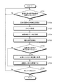
次に、図10を用いて、車両用投影制御装置40における処理の流れについて説明する。図10は、第一実施形態に係る車両用投影制御装置における処理の流れを示すフローチャートである。本実施形態では、HUD装置10の起動中、車両用投影制御装置40は、1秒間のうち1フレームにおいて基準位置判定用映像100を投影して、1秒間のうち残りのフレームにおいて表示映像200を投影するものとして説明する。
車両用投影制御装置40は、基準位置判定用映像100の投影タイミングであるか否かを判定する(ステップST11)。より詳しくは、車両用投影制御装置40は、1秒間におけるフレームをカウントして基準位置判定用映像100を投影するタイミングであるか否かを判定する。車両用投影制御装置40は、基準位置判定用映像100を投影するタイミングである場合(ステップST11でYes)、ステップST12に進む。車両用投影制御装置40は、基準位置判定用映像100を投影するタイミングではない場合(ステップST11でNo)、ステップST11の処理を再度実行する。
基準位置判定用映像100を投影するタイミングであると判定された場合(ステップST11でYes)、車両用投影制御装置40は、基準位置判定用映像100を投影する(ステップST12)。より詳しくは、車両用投影制御装置40は、投影制御部45によって、基準位置判定用映像生成部41が生成した基準位置判定用映像100を投影する制御信号を出力する。車両用投影制御装置40は、ステップST13に進む。
車両用投影制御装置40は、カメラ20によって撮影する(ステップST13)。より詳しくは、車両用投影制御装置40は、カメラ20によって、運転者Mの顔面に投影された基準位置判定用映像100を撮影映像データとして撮影する。車両用投影制御装置40は、ステップST14に進む。
車両用投影制御装置40は、撮影映像データを取得する(ステップST14)。より詳しくは、車両用投影制御装置40は、映像データ取得部42によって、カメラ20が撮影した撮影映像データを取得する。車両用投影制御装置40は、ステップST15に進む。
車両用投影制御装置40は、瞳孔位置を検出する(ステップST15)。より詳しくは、車両用投影制御装置40は、検出部43によって、撮影映像データに対して画像処理を行って、基準位置判定用映像100と運転者Mの瞳孔との相対的な位置関係を検出する。車両用投影制御装置40は、検出部43によって、運転者Mの瞳孔位置のズレ量を検出する。車両用投影制御装置40は、ステップST16に進む。
車両用投影制御装置40は、運転者Mの姿勢が所定姿勢であるか否かを判定する(ステップST16)。より詳しくは、車両用投影制御装置40は、検出部43が検出した運転者Mの瞳孔位置の上下方向または左右方向のズレ量が閾値以上である場合、運転者Mの姿勢が所定姿勢ではないと判定して(ステップST16でYes)、ステップST17に進む。車両用投影制御装置40は、検出部43が検出した運転者Mの瞳孔位置の上下方向または左右方向のズレ量が閾値以上ではない場合、運転者Mの姿勢が所定姿勢であると判定して(ステップST16でNo)、ステップST19に進む。
運転者Mの姿勢が所定姿勢ではないと判定された場合(ステップST16でYes)、車両用投影制御装置40は、警告映像生成部44によって、警告映像300を生成する(ステップST17)。車両用投影制御装置40は、ステップST18に進む。
車両用投影制御装置40は、警告映像300を投影する(ステップST18)。車両用投影制御装置40は、投影制御部45によって、警告映像生成部44が取得した警告映像300を表示映像200とともに投影する制御信号を出力する。車両用投影制御装置40は、ステップST19に進む。
車両用投影制御装置40は、終了トリガがあるか否かを判定する(ステップST19)。終了トリガとは、例えば、HUD装置10の動作を終了するボタンが押下されたり、車両が停車してエンジンが停止された場合である。車両用投影制御装置40は、終了トリガがある場合(ステップST19でYes)、処理を終了する。車両用投影制御装置40は、終了トリガがない場合(ステップST19でNo)、ステップST11の処理を再度実行する。
このようにして、車両用投影制御装置40は、基準位置判定用映像100の映像表示光を運転者Mの顔面に投射することによって、運転者Mの瞳孔位置から虚像に対する姿勢として頭部位置を検出する。そして、車両用投影制御装置40は、運転者Mが適切な所定姿勢からずれているとき、警告映像300を投影する。
上述したように、本実施形態は、基準位置判定用映像100の映像表示光を運転者Mの顔面に投射することによって、基準位置判定用映像100と運転者Mの瞳孔との相対的な位置関係を検出する。これにより、本実施形態は、虚像に対する運転者Mの姿勢として頭部位置を検出することができる。
本実施形態は、検出した虚像に対する運転者Mの姿勢が所定姿勢ではないとき、言い換えると、運転者Mの頭部位置が適切な位置からズレているとき、警告映像300を運転者Mに対して虚像として視認させることができる。本実施形態によれば、運転者Mの姿勢が適切な所定姿勢からはずれていることを、運転者Mに認識させることができる。これにより、本実施形態によれば、瞳孔位置が大きくズレて、表示映像200の虚像が正しく視認されないような状態となることを抑制することができる。本実施形態は、虚像を適切に運転者Mに視認させることが可能になる。
本実施形態は、1秒間のうちの1フレームのみ基準位置判定用映像100を投影する。これにより、本実施形態は、運転者Mの顔面に基準位置判定用映像100の映像表示光が投射されていることを運転者Mに意識させることなく、虚像に対する運転者Mの姿勢として頭部位置を検出することができる。
本実施形態は、通常使用時における表示映像200の映像表示光の光路と同一の光路を通過して、表示映像200の投影位置と同じ位置に投影される基準位置判定用映像100の映像表示光を運転者Mの顔面に投射する。このように、本実施形態は、基準位置判定用映像100の映像表示光を運転者Mの顔面に投射することにより、虚像に対する運転者Mの姿勢として頭部位置を直接的に検出することができる。
本実施形態では、カメラ20と投影ユニット30と車両用投影制御装置40とは、一体として、車両のダッシュボードDの下側に配置されている。本実施形態は、通常使用時に表示映像200の虚像を投影する装置によって、虚像に対する運転者Mの姿勢として頭部位置を検出することができる。本実施形態は、表示映像200の投影を行う装置以外の装置を車両のダッシュボードDなどに取り付けなくてよいので、装置が大型化することを抑制することができる。
[第二実施形態]
図11ないし図13を参照しながら、本実施形態に係るHUD装置10Aについて説明する。図11は、第二実施形態に係る車両用投影制御装置の構成例を示すブロック図である。図12は、第二実施形態に係る車両用投影制御装置によって検出される運転者の瞳孔位置の一例を示す図である。図13は、第二実施形態に係る車両用投影制御装置における処理の流れを示すフローチャートである。HUD装置10Aは、基本的な構成は第一実施形態のHUD装置10と同様である。以下の説明においては、HUD装置10と同様の構成要素には、同一の符号または対応する符号を付し、その詳細な説明は省略する。本実施形態では、HUD装置10Aは、大きさ調整量取得部46Aを有する点と、検出部43Aと投影制御部45Aとにおける処理が第一実施形態と異なる。
図11ないし図13を参照しながら、本実施形態に係るHUD装置10Aについて説明する。図11は、第二実施形態に係る車両用投影制御装置の構成例を示すブロック図である。図12は、第二実施形態に係る車両用投影制御装置によって検出される運転者の瞳孔位置の一例を示す図である。図13は、第二実施形態に係る車両用投影制御装置における処理の流れを示すフローチャートである。HUD装置10Aは、基本的な構成は第一実施形態のHUD装置10と同様である。以下の説明においては、HUD装置10と同様の構成要素には、同一の符号または対応する符号を付し、その詳細な説明は省略する。本実施形態では、HUD装置10Aは、大きさ調整量取得部46Aを有する点と、検出部43Aと投影制御部45Aとにおける処理が第一実施形態と異なる。
検出部43Aは、撮影映像データにおける運転者Mの瞳孔位置と基準位置判定用映像100とに基づいて、表示映像200の虚像に対する運転者Mの瞳孔位置の前後方向のズレを検出する。より詳しくは、検出部43Aは、撮影映像データに対して画像処理を行って、基準位置判定用映像100に含まれる線の太さが閾値範囲外の太さのとき、表示映像200の虚像に対する運転者Mの瞳孔位置が前後方向にズレを有し、所定姿勢ではないと検出する。検出部43Aは、図12に示すように、基準位置判定用映像100に含まれる線の太さが閾値範囲以上のとき、表示映像200の虚像に対する運転者Mの瞳孔位置が後方向にズレを有し、所定姿勢ではないと検出する。検出部43Aは、基準位置判定用映像100に含まれる線の太さが閾値範囲以下のとき、表示映像200の虚像に対する運転者Mの瞳孔位置が前方向にズレを有し、所定姿勢ではないと検出する。
大きさ調整量取得部46Aは、検出部43Aが検出した運転者Mの姿勢に基づいて、前方に投影する虚像の大きさの調整量を取得する。より詳しくは、大きさ調整量取得部46Aは、運転者Mの瞳孔位置が前方向にズレを有し、所定姿勢ではないとき、所定姿勢で視認する虚像と同じ大きさの虚像を視認させるため、虚像が大きく表示される調整量を取得する。大きさ調整量取得部46Aは、運転者Mの瞳孔位置が後方向にズレを有し、所定姿勢ではないとき、所定姿勢で視認する虚像と同じ大きさの虚像を視認させるため、虚像が小さく表示される調整量を取得する。
投影制御部45Aは、表示映像200の虚像に対する運転者Mの瞳孔位置が前後方向にズレを有するとき、大きさ調整量取得部46Aが取得した調整量に基づいて、前方に投影する虚像の大きさを調整して投影する。
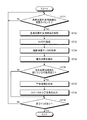
次に、図13を用いて、車両用投影制御装置40Aにおける処理の流れについて説明する。図13に示すフローチャートのステップST21ないしステップST25、ステップST29の処理は、図10に示すフローチャートのステップST11ないしステップST15、ステップST19の処理と同様の処理を行う。
車両用投影制御装置40Aは、運転者Mの姿勢が所定姿勢であるか否かを判定する(ステップST26)。より詳しくは、車両用投影制御装置40Aは、検出部43Aが検出した運転者Mの瞳孔位置の前後方向のズレ量が閾値以上である場合、運転者Mの姿勢が所定姿勢ではないと判定し(ステップST26でYes)、ステップST27に進む。車両用投影制御装置40Aは、検出部43Aが検出した運転者Mの瞳孔位置の前後方向のズレ量が閾値以下である場合、運転者Mの姿勢が所定姿勢であると判定し(ステップST26でNo)、ステップST29に進む。
車両用投影制御装置40Aは、大きさ調整量取得部46Aによって虚像位置の大きさの調整量を取得する(ステップST27)。車両用投影制御装置40Aは、ステップST28に進む。
車両用投影制御装置40Aは、虚像の大きさを調整する(ステップST28)。より詳しくは、車両用投影制御装置40Aは、投影制御部45Aによって、大きさ調整量取得部46Aが取得した調整量に基づいて、前方に投影する虚像の大きさを調整して投影する。車両用投影制御装置40Aは、ステップST29に進む。
上述したように、本実施形態は、姿勢検出時に、瞳孔位置の前後方向のズレが閾値以上である姿勢のとき、虚像の大きさを調整する。本実施形態によれば、瞳孔位置が前後方向に大きくズレて、表示映像200の虚像が正しく視認されないような状態となることを抑制することができる。
[第三実施形態]
図14、図15を参照しながら、本実施形態に係るHUD装置10Bについて説明する。図14は、第三実施形態に係る車両用投影制御装置の構成例を示すブロック図である。図15は、第三実施形態に係る車両用投影制御装置における処理の流れを示すフローチャートである。HUD装置10Bは、基本的な構成は第一実施形態のHUD装置10と同様である。本実施形態では、HUD装置10Bは、眠気判定部47Bと警告情報生成部48Bと出力制御部49Bとを有する点と、投影制御部45Bとにおける処理が第一実施形態と異なる。
図14、図15を参照しながら、本実施形態に係るHUD装置10Bについて説明する。図14は、第三実施形態に係る車両用投影制御装置の構成例を示すブロック図である。図15は、第三実施形態に係る車両用投影制御装置における処理の流れを示すフローチャートである。HUD装置10Bは、基本的な構成は第一実施形態のHUD装置10と同様である。本実施形態では、HUD装置10Bは、眠気判定部47Bと警告情報生成部48Bと出力制御部49Bとを有する点と、投影制御部45Bとにおける処理が第一実施形態と異なる。
HUD装置10Bは、さらに、警告音を出力可能なスピーカ50Bを有する。
眠気判定部47Bは、検出部43が検出した運転者Mの姿勢に基づいて、運転者Mが眠気を感じているか否かを判定する。より詳しくは、眠気判定部47Bは、運転者Mの姿勢が所定姿勢ではなく、例えば、運転者Mの頭部位置が上下方向または左右方向または前後方向に往復運動をしている状態のとき、運転者Mが眠気を感じている可能性があるとして判定する。または、眠気判定部47Bは、運転者Mの姿勢が所定姿勢ではなく、例えば、運転者Mの頭部位置が上下方向または左右方向または前後方向に繰り返し大きく変化する状態のとき、運転者Mが眠気を感じている可能性があるとして判定する。眠気判定部47Bは、運転者Mの姿勢が所定姿勢ではない状態が所定時間継続している状態のとき、運転者Mが眠気を感じている可能性があるとして判定することが好ましい。
または、眠気判定部47Bは、運転者Mが眼を閉じていて瞳孔を検出できない状態が所定時間継続している状態のとき、運転者Mが眠気を感じている可能性があるとして判定してもよい。
警告情報生成部48Bは、検出部43の検出結果に基づいて、運転者Mが眠気を感じている可能性があるとき、運転者Mに警告を報知する警告情報を生成する。
出力制御部49Bは、眠気判定部47Bによって運転者Mが眠気を感じている可能性があると判定された場合、警告情報生成部48Bが生成した警告情報である警告音を出力するように制御する。
次に、図15を用いて、車両用投影制御装置40Bにおける処理の流れについて説明する。図15に示すフローチャートのステップST31ないしステップST35、ステップST39の処理は、図10に示すフローチャートのステップST11ないしステップST15、ステップST19の処理と同様の処理を行う。
車両用投影制御装置40Bは、運転者Mが眠気を感じている可能性があるか否かを判定する(ステップST36)。より詳しくは、車両用投影制御装置40Bは、検出部43が検出した運転者Mの瞳孔位置の変化パターンが、運転者Mが眠気を感じているときの特徴に当てはまる場合、運転者Mが眠気を感じている可能性があると判定し(ステップST36でYes)、ステップST37に進む。より詳しくは、車両用投影制御装置40Bは、検出部43が検出した運転者Mの瞳孔位置の変化パターンが、運転者Mが眠気を感じているときの特徴に当てはまる場合、運転者Mが眠気を感じている可能性があると判定し(ステップST36でYes)、ステップST37に進む。または、車両用投影制御装置40Bは、検出部43が運転者Mの瞳孔位置を検出できない状態が所定時間継続している場合、運転者Mが眠気を感じて目を閉じている可能性があると判定し(ステップST36でYes)、ステップST37に進む。車両用投影制御装置40Bは、検出部43が検出した運転者Mの瞳孔位置の変化パターンが、運転者Mが眠気を感じているときの特徴に当てはまらない場合、運転者Mが眠気を感じている可能性がないと判定し(ステップST36でNo)、ステップST39に進む。
運転者Mが眠気を感じていると判定された場合(ステップST36でYes)、車両用投影制御装置40Bは、警告情報を生成する(ステップST37)。車両用投影制御装置40Bは、ステップST38に進む。
車両用投影制御装置40Bは、スピーカ50Bから警告音を出力する(ステップST38)。車両用投影制御装置40Bは、出力制御部49Bによって、スピーカ50Bから警告音を出力する制御信号を出力する。車両用投影制御装置40Bは、ステップST39に進む。
上述したように、本実施形態は、検出部43が検出した運転者Mの姿勢である頭部位置に基づいて、運転者Mが眠気を感じているか否かを判定することができる。または、本実施形態は、検出部43が運転者Mの瞳孔位置を検出できない状態が所定時間継続していることによって、運転者Mが眠気を感じているか否かを判定することができる。このようにして、本実施形態によれば、運転者Mが眠気を感じている可能性を判定することによって、警告を発することができる。
さて、これまで本発明に係るHUD装置10について説明したが、上述した実施形態以外にも種々の異なる形態にて実施されてよいものである。
図示したHUD装置10の各構成要素は、機能概念的なものであり、必ずしも物理的に図示の如く構成されていなくてもよい。すなわち、各装置の具体的形態は、図示のものに限られず、各装置の処理負担や使用状況などに応じて、その全部または一部を任意の単位で機能的または物理的に分散または統合してもよい。
HUD装置10の構成は、例えば、ソフトウェアとして、メモリにロードされたプログラムなどによって実現される。上記実施形態では、これらのハードウェアまたはソフトウェアの連携によって実現される機能ブロックとして説明した。すなわち、これらの機能ブロックについては、ハードウェアのみ、ソフトウェアのみ、または、それらの組み合わせによって種々の形で実現できる。
上記した構成要素には、当業者が容易に想定できるもの、実質的に同一のものを含む。さらに、上記した構成は適宜組み合わせが可能である。また、本発明の要旨を逸脱しない範囲において構成の種々の省略、置換または変更が可能である。
投影ユニット30は、ウィンドシールドSを反射部とするものとして説明したが、反射部はこれに限定されない。例えば、コンバイナを反射部として使用するものでもよい。
基準位置判定用映像100は、可視光を使用するものに限定されず、赤外光を使用してもよい。基準位置判定用映像100に赤外光を使用した場合、カメラ20は、赤外光を撮影可能な赤外カメラとする。基準位置判定用映像100に赤外光を使用することにより、運転者Mの顔面に基準位置判定用映像100の映像表示光が投射されていることを運転者Mに意識させることなく、運転者Mの瞳孔位置を検出することが可能である。
10 HUD装置
20 カメラ
30 投影ユニット
31 表示部
32 凹面鏡
40 車両用投影制御装置(投影制御装置)
41 基準位置判定用映像生成部
42 映像データ取得部
43 検出部
44 警告映像生成部(警告情報生成部)
45 投影制御部(出力制御部)
100 基準位置判定用映像
101 第一基準位置判定用映像
102 第二基準位置判定用映像
200 表示映像
300 警告映像
S ウィンドシールド
20 カメラ
30 投影ユニット
31 表示部
32 凹面鏡
40 車両用投影制御装置(投影制御装置)
41 基準位置判定用映像生成部
42 映像データ取得部
43 検出部
44 警告映像生成部(警告情報生成部)
45 投影制御部(出力制御部)
100 基準位置判定用映像
101 第一基準位置判定用映像
102 第二基準位置判定用映像
200 表示映像
300 警告映像
S ウィンドシールド
Claims (9)
- 視認者の前方に虚像が視認されるように表示映像の投影を制御する投影制御部と、
視認者を撮影可能な撮影部が撮影した撮影映像を取得する映像データ取得部と、
前記虚像に対する前記視認者の瞳孔位置の相対的な位置関係に基づいて、前記視認者が前記虚像を視認する際の姿勢を検出する検出部と、
を備え、
前記投影制御部は、前記視認者に向けて投射する基準位置判定用映像の投影を制御し、
前記検出部は、前記映像データ取得部が取得した、前記視認者に投射された前記基準位置判定用映像を撮影した撮影映像から、前記虚像に対する前記視認者の瞳孔位置の相対的な位置関係に基づいて、前記視認者が前記虚像を視認する際の姿勢を検出する、
ことを特徴とする投影制御装置。 - 前記検出部が検出した前記視認者の姿勢に基づいて、前記視認者が前記虚像を視認する際の姿勢が所定姿勢ではないと、前記視認者に警告を報知する警告情報を生成する警告情報生成部と、
前記警告情報生成部が生成した前記警告情報の出力を制御する出力制御部と、
を備える請求項1に記載の投影制御装置。 - 前記警告情報生成部は、前記警告情報として、警告映像を生成する警告映像生成部であり、
前記出力制御部は、前記警告情報生成部が生成した前記警告情報が、前方に虚像として視認されるように警告映像の投影を制御する投影制御部である、
請求項2に記載の投影制御装置。 - 前記検出部が検出した前記視認者の姿勢に基づいて、前方に投影する虚像の大きさの調整量を取得する大きさ調整量取得部、
を備え、
前記投影制御部は、前記大きさ調整量取得部が取得した前記調整量に基づいて、前方に投影する虚像の大きさを調整して投影するよう制御する、
請求項1から3のいずれか一項に記載の投影制御装置。 - 前記検出部が検出した前記視認者の姿勢に基づいて、前記視認者が眠気を感じているか否かを判定する眠気判定部、
を備える請求項1から4のいずれか一項に記載の投影制御装置。 - 前記基準位置判定用映像は、上下方向の基準位置を示す第一基準位置判定用映像と左右方向の基準位置を示す第二基準位置判定用映像との少なくともいずれかを含む、
請求項1から5のいずれか一項に記載の投影制御装置。 - 請求項1から6のいずれか一項に記載の投影制御装置と、
投影ユニットと前記撮影部との少なくともいずれかと、
を備えることを特徴とするヘッドアップディスプレイ装置。 - 視認者の前方に虚像が視認されるように表示映像の投影を制御する投影制御ステップと、
視認者を撮影可能な撮影部が撮影した撮影映像を取得する映像データ取得ステップと、
前記虚像に対する前記視認者の瞳孔位置の相対的な位置関係に基づいて、前記視認者が前記虚像を視認する際の姿勢を検出する検出ステップと、
を含み、
前記投影制御ステップは、前記視認者に向けて投射する基準位置判定用映像の投影を制御し、
前記検出ステップは、前記映像データ取得ステップによって取得した、前記視認者に投射された前記基準位置判定用映像を撮影した撮影映像から、前記虚像に対する前記視認者の瞳孔位置の相対的な位置関係に基づいて、前記視認者が前記虚像を視認する際の姿勢を検出する、
投影制御方法。 - 視認者の前方に虚像が視認されるように表示映像の投影を制御する投影制御ステップと、
視認者を撮影可能な撮影部が撮影した撮影映像を取得する映像データ取得ステップと、
前記虚像に対する前記視認者の瞳孔位置の相対的な位置関係に基づいて、前記視認者が前記虚像を視認する際の姿勢を検出する検出ステップと、
を含み、
前記投影制御ステップは、前記視認者に向けて投射する基準位置判定用映像の投影を制御し、
前記検出ステップは、前記映像データ取得ステップによって取得した、前記視認者に投射された前記基準位置判定用映像を撮影した撮影映像から、前記虚像に対する前記視認者の瞳孔位置の相対的な位置関係に基づいて、前記視認者が前記虚像を視認する際の姿勢を検出する、
ことを投影制御装置として動作するコンピュータに実行させるためのプログラム。
Applications Claiming Priority (2)
| Application Number | Priority Date | Filing Date | Title |
|---|---|---|---|
| JP2017254001A JP2019119281A (ja) | 2017-12-28 | 2017-12-28 | 投影制御装置、ヘッドアップディスプレイ装置、投影制御方法およびプログラム |
| JP2017-254001 | 2017-12-28 |
Publications (1)
| Publication Number | Publication Date |
|---|---|
| WO2019130865A1 true WO2019130865A1 (ja) | 2019-07-04 |
Family
ID=67066975
Family Applications (1)
| Application Number | Title | Priority Date | Filing Date |
|---|---|---|---|
| PCT/JP2018/041966 Ceased WO2019130865A1 (ja) | 2017-12-28 | 2018-11-13 | 投影制御装置、ヘッドアップディスプレイ装置、投影制御方法およびプログラム |
Country Status (2)
| Country | Link |
|---|---|
| JP (1) | JP2019119281A (ja) |
| WO (1) | WO2019130865A1 (ja) |
Families Citing this family (1)
| Publication number | Priority date | Publication date | Assignee | Title |
|---|---|---|---|---|
| JP7579504B2 (ja) * | 2020-11-27 | 2024-11-08 | 日本精機株式会社 | 表示制御装置、ヘッドアップディスプレイ装置及び、表示制御方法 |
Citations (4)
| Publication number | Priority date | Publication date | Assignee | Title |
|---|---|---|---|---|
| JP4686586B2 (ja) * | 2008-09-19 | 2011-05-25 | 株式会社東芝 | 車載用表示装置及び表示方法 |
| JP2013056633A (ja) * | 2011-09-09 | 2013-03-28 | Honda Motor Co Ltd | ヘッドアップディスプレイ装置 |
| JP2017030390A (ja) * | 2015-07-29 | 2017-02-09 | 修一 田山 | 車輌の自動運転システム |
| JP2017206245A (ja) * | 2017-06-20 | 2017-11-24 | 株式会社ユピテル | 車両用投影システム及びそのプログラム |
-
2017
- 2017-12-28 JP JP2017254001A patent/JP2019119281A/ja active Pending
-
2018
- 2018-11-13 WO PCT/JP2018/041966 patent/WO2019130865A1/ja not_active Ceased
Patent Citations (4)
| Publication number | Priority date | Publication date | Assignee | Title |
|---|---|---|---|---|
| JP4686586B2 (ja) * | 2008-09-19 | 2011-05-25 | 株式会社東芝 | 車載用表示装置及び表示方法 |
| JP2013056633A (ja) * | 2011-09-09 | 2013-03-28 | Honda Motor Co Ltd | ヘッドアップディスプレイ装置 |
| JP2017030390A (ja) * | 2015-07-29 | 2017-02-09 | 修一 田山 | 車輌の自動運転システム |
| JP2017206245A (ja) * | 2017-06-20 | 2017-11-24 | 株式会社ユピテル | 車両用投影システム及びそのプログラム |
Also Published As
| Publication number | Publication date |
|---|---|
| JP2019119281A (ja) | 2019-07-22 |
Similar Documents
| Publication | Publication Date | Title |
|---|---|---|
| USRE50732E1 (en) | Head up display apparatus and display control method thereof | |
| US11597278B2 (en) | Projection control device, head-up display device, projection control method, and non-transitory storage medium | |
| US20060262140A1 (en) | Method and apparatus to facilitate visual augmentation of perceived reality | |
| JP6554131B2 (ja) | 車両の表示システム及び車両の表示システムの制御方法 | |
| US20200051529A1 (en) | Display device, display control method, and storage medium | |
| TW201939102A (zh) | 抬頭顯示系統及其控制方法 | |
| JP6857695B2 (ja) | 後方表示装置、後方表示方法、およびプログラム | |
| JP2009246505A (ja) | 画像表示装置及び画像表示装置 | |
| US11176749B2 (en) | In-vehicle display device three-dimensional image generation | |
| KR20180022374A (ko) | 운전석과 보조석의 차선표시 hud와 그 방법 | |
| JP6482975B2 (ja) | 画像生成装置および画像生成方法 | |
| JP2010130647A (ja) | 車両周辺確認装置 | |
| US20190122058A1 (en) | Vehicle display controller, vehicle display system, vehicle display control method, and non-transitory storage medium | |
| JP4692496B2 (ja) | 車両用表示装置 | |
| CN110733423B (zh) | 用于显示车辆后方图像的装置和方法 | |
| JP2025168437A (ja) | 撮影装置、制御方法、プログラム及び記憶媒体 | |
| CN117647889A (zh) | 车辆用显示装置 | |
| WO2019130865A1 (ja) | 投影制御装置、ヘッドアップディスプレイ装置、投影制御方法およびプログラム | |
| US20240371170A1 (en) | Information processing device, and control program | |
| JP2021115911A (ja) | 表示制御装置、表示システム、表示制御方法及びプログラム | |
| JP6813437B2 (ja) | 表示システム | |
| JP2018084767A (ja) | 表示制御装置、制御方法、プログラム及び記憶媒体 | |
| JP2004306792A (ja) | ヘッドアップディスプレイ | |
| JP2020006743A (ja) | 車両用投影制御装置、ヘッドアップディスプレイ装置、車両用投影制御方法およびプログラム | |
| JP2022153128A (ja) | インキャビンモニタリングシステムおよび撮像方法 |
Legal Events
| Date | Code | Title | Description |
|---|---|---|---|
| 121 | Ep: the epo has been informed by wipo that ep was designated in this application |
Ref document number: 18894368 Country of ref document: EP Kind code of ref document: A1 |
|
| NENP | Non-entry into the national phase |
Ref country code: DE |
|
| 122 | Ep: pct application non-entry in european phase |
Ref document number: 18894368 Country of ref document: EP Kind code of ref document: A1 |