WO2019130671A1 - 熱電変換シート - Google Patents
熱電変換シート Download PDFInfo
- Publication number
- WO2019130671A1 WO2019130671A1 PCT/JP2018/033919 JP2018033919W WO2019130671A1 WO 2019130671 A1 WO2019130671 A1 WO 2019130671A1 JP 2018033919 W JP2018033919 W JP 2018033919W WO 2019130671 A1 WO2019130671 A1 WO 2019130671A1
- Authority
- WO
- WIPO (PCT)
- Prior art keywords
- sheet
- thermoelectric conversion
- resin
- high temperature
- main body
- Prior art date
- Legal status (The legal status is an assumption and is not a legal conclusion. Google has not performed a legal analysis and makes no representation as to the accuracy of the status listed.)
- Ceased
Links
Images




Classifications
-
- H—ELECTRICITY
- H02—GENERATION; CONVERSION OR DISTRIBUTION OF ELECTRIC POWER
- H02N—ELECTRIC MACHINES NOT OTHERWISE PROVIDED FOR
- H02N11/00—Generators or motors not provided for elsewhere; Alleged perpetua mobilia obtained by electric or magnetic means
-
- H—ELECTRICITY
- H10—SEMICONDUCTOR DEVICES; ELECTRIC SOLID-STATE DEVICES NOT OTHERWISE PROVIDED FOR
- H10N—ELECTRIC SOLID-STATE DEVICES NOT OTHERWISE PROVIDED FOR
- H10N10/00—Thermoelectric devices comprising a junction of dissimilar materials, i.e. devices exhibiting Seebeck or Peltier effects
- H10N10/10—Thermoelectric devices comprising a junction of dissimilar materials, i.e. devices exhibiting Seebeck or Peltier effects operating with only the Peltier or Seebeck effects
- H10N10/13—Thermoelectric devices comprising a junction of dissimilar materials, i.e. devices exhibiting Seebeck or Peltier effects operating with only the Peltier or Seebeck effects characterised by the heat-exchanging means at the junction
-
- H—ELECTRICITY
- H10—SEMICONDUCTOR DEVICES; ELECTRIC SOLID-STATE DEVICES NOT OTHERWISE PROVIDED FOR
- H10N—ELECTRIC SOLID-STATE DEVICES NOT OTHERWISE PROVIDED FOR
- H10N10/00—Thermoelectric devices comprising a junction of dissimilar materials, i.e. devices exhibiting Seebeck or Peltier effects
- H10N10/10—Thermoelectric devices comprising a junction of dissimilar materials, i.e. devices exhibiting Seebeck or Peltier effects operating with only the Peltier or Seebeck effects
- H10N10/17—Thermoelectric devices comprising a junction of dissimilar materials, i.e. devices exhibiting Seebeck or Peltier effects operating with only the Peltier or Seebeck effects characterised by the structure or configuration of the cell or thermocouple forming the device
Definitions
- the present invention relates to a thermoelectric conversion sheet in which conversion between thermal energy and electrical energy is performed.
- thermoelectric conversion device using a thermoelectric conversion element capable of converting thermal energy and electrical energy is used for various applications.
- the thermoelectric conversion element can convert thermal energy into electrical energy, and thus is used as, for example, a main member of a power generation device or a temperature measurement device. Since the thermoelectric conversion element can convert thermal energy directly into electrical energy, the configuration of the device as described above can be simplified.
- a part of the area is a high temperature area where the temperature is relatively high compared to the other areas, and the other area is a low temperature area where the temperature is relatively lower than the high temperature area.
- thermoelectric conversion element This has a function of moving electrons and holes from the high temperature region to the low temperature region, or moving electrons and holes from the low temperature region to the high temperature region. Since the potential difference generated in one thermoelectric conversion element due to such a temperature difference is weak, this type of thermoelectric conversion element is usually made into a plurality of aggregations, and individual thermoelectric conversion elements constituting the aggregation It is used in the form of connecting in series.
- Patent Document 1 it is shown that columnar thermoelectric conversion elements formed of an inorganic sintered body stand on a substrate, and adjacent thermoelectric conversion elements are electrically connected to each other at the bottom or at the top. (See, for example, FIG. 1 of Patent Document 1).
- a sheet-like thermoelectric conversion element such as a resin sheet in place of such an inorganic sintered body has been studied (see Patent Document 2 below).
- Sheet-like thermoelectric conversion elements are advantageous in that they can be thinner and have excellent flexibility as compared to inorganic sintered bodies.
- the effect of thinness and flexibility is to form one large thermoelectric conversion sheet by, for example, arranging the thermoelectric conversion elements in a planar direction even when forming an aggregate with a plurality of sheet-like thermoelectric conversion elements. Can be demonstrated.
- thermoelectric conversion sheet in which a plurality of thermoelectric conversion elements are arranged as described above, the thermoelectric conversion sheet is formed on the surface of the heating element It is difficult to expect that a high electromotive force will occur because a temperature difference does not occur in the thermoelectric conversion elements by merely bringing them into contact. Therefore, in the case where the thermoelectric conversion sheet is subjected to the thermoelectric conversion in such a mode that heat is received from one side and the heat is released from the other side, it is usually necessary to devise a method for generating a temperature difference in the thermoelectric conversion element.
- thermoelectric conversion element for example, an air-cooled radiator such as a radiation fin or a refrigerant circulating radiator is attached, and a part of the thermoelectric conversion element is cooled by the radiator A similar method is conceivable.
- the merit of the sheet-like thermoelectric conversion sheet is not sufficiently reflected, and the entire structure including the radiator may be complicated and bulky. That is, with regard to a thermoelectric conversion sheet used in a mode that receives heat from one side and dissipates heat from the other side, a temperature difference is provided to the thermoelectric conversion elements while suppressing the structure from becoming complicated and bulky. Has the problem of being difficult.
- thermoelectric conversion sheet used for thermoelectric conversion, which receives a heat from one side, dissipates heat from the other side, and performs the thermoelectric conversion from the one side.
- a plurality of sheet-like thermoelectric conversion elements smaller in area than the sheet main body are disposed on the sheet main body, and a base sheet in contact with the sheet main body and a metal sheet in contact with the sheet main body from the other side.
- the plurality of thermoelectric conversion elements are electrically connected in series to constitute one conduction path, and each of the plurality of thermoelectric conversion elements is directed in one direction of the conduction path.
- a high temperature area which is relatively high temperature to be generated and a low temperature area which is relatively low temperature are provided, the metal sheet is disposed so as to cover the high temperature area from the other surface side, and the substrate Sheet The has both the high temperature region and the low temperature region is disposed to cover from the one surface side, the thermal conductivity of the base sheet to provide a thermoelectric conversion sheet is less than 8W / mK.
- thermoelectric conversion sheet according to one aspect of the present invention, the area ratio of the portion where the thermoelectric conversion element is covered by the metal sheet is 40% or more and 60% or less.
- thermoelectric conversion sheet according to the other aspect of the present invention, the thermal conductivity of the base sheet is 1.5 W / mK or less.
- thermoelectric conversion sheet in the thermoelectric conversion sheet according to another aspect of the present invention, is an aluminum foil.
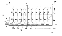
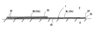
- thermoelectric conversion sheet (bipolar type) which concerns on 1st Embodiment. II-II 'arrow directional cross-sectional view in FIG.
- the schematic plan view of the thermoelectric conversion sheet (unileg type
- the schematic plan view of the thermoelectric conversion sheet (unileg type
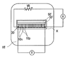
- the top view which showed the electric current in an Example, and the voltage measurement method.
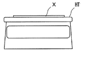
- the side view showing the current and voltage measuring method in an example.
- thermoelectric conversion sheet of the present embodiment is a sheet used for converting thermal energy and electrical energy.
- thermoelectric conversion sheet of the present invention As a first embodiment of the thermoelectric conversion sheet of the present invention, a p-type thermoelectric conversion element (hereinafter, also referred to as “p-type thermoelectric conversion element”) and an n-type thermoelectric conversion element (hereinafter, “n-type thermoelectric conversion element”
- p-type thermoelectric conversion element also referred to as "p-type thermoelectric conversion element”
- n-type thermoelectric conversion element The “bipolar-type thermoelectric conversion sheet” will be described.
- the thermoelectric conversion sheet 100 according to the first embodiment is used in contact with the heating element A whose temperature is higher than that of the surrounding air V, and the temperatures of the heating element A and the surrounding air V are used. It is used for thermoelectric conversion using the difference.
- thermoelectric conversion sheet 100 receives heat from one surface side (heating element side), dissipates heat from the other surface side (peripheral air side), and is in contact with the sheet main body 1 from the one surface side.
- a base sheet 40 and a metal sheet 50 in contact with the sheet main body 1 from the other side are provided.
- a plurality of sheet-like thermoelectric conversion elements 10 having a smaller area than the sheet main body 1 are disposed on the sheet main body 1 of the thermoelectric conversion sheet 100, and the plurality of thermoelectric conversion elements 10 are electrically connected in series. And constitute one conduction path.
- Each of the plurality of thermoelectric conversion elements 10 is provided with a high temperature region which is made relatively high temperature to generate a voltage toward one direction of the conduction path, and a low temperature region which is made relatively low temperature.
- the metal sheet 50 is disposed to cover the high temperature area from the other surface side, and the base sheet 40 is disposed to cover both the high temperature area and the low temperature area from the one surface side. .
- thermoelectric conversion sheet 100 which concerns on 1st Embodiment is used for thermoelectric conversion in the form mounted on the heat generating body A arrange
- the thermoelectric conversion sheet 100 includes a rectangular sheet main body 1 in which the transverse direction is a longitudinal direction (hereinafter, also referred to as “length direction L”) and the longitudinal direction is a transverse direction (hereinafter, also referred to as “width direction W”). ing.
- thermoelectric conversion elements 10 are disposed in the sheet main body 1 of the present embodiment, and a plurality of p-type thermoelectric conversion elements 10 p and a plurality of n-type thermoelectric conversion elements 10 n are provided as the thermoelectric conversion elements 10. .
- the sheet body 1 further includes two laminate films 20 and 20 'which define the overall shape of the sheet body 1. That is, the shape of the laminate film 20, 20 'is a horizontally long rectangular as in the sheet main body 1.
- thermoelectric conversion element 10p and the n-type thermoelectric conversion element 10n are sandwiched between the two laminate films 20 and 20 '.
- the sheet body 1 electrically connects the p-type thermoelectric conversion element 10p and the n-type thermoelectric conversion element 10n disposed between the laminate films, and the electrical energy generated in these thermoelectric conversion elements 10p and 10n is outside the sheet body
- a wire 30 for leading to the Like the thermoelectric conversion element 10 the wire 30 is sandwiched between two laminate films 20 and 20 '.
- the wiring 30 forms a conduction path of the thermoelectric conversion sheet 100 together with the thermoelectric conversion elements 10 p and 10 n.
- the conduction path is such that the direction of the voltage generated in each thermoelectric conversion element when the sheet main body 1 receives heat from one side (the lower surface) is one direction, and a plurality of electric current I generated by the voltage.
- the thermoelectric conversion elements 10p and 10n are configured to be arranged in series.
- the thermoelectric conversion sheet 100 of the present embodiment includes the base sheet 40 covering the sheet main body 1 from one side as described above.
- the base sheet 40 of the present embodiment has a shape corresponding to the laminate films 20 and 20 ', and is adhered to the lower surface side of the sheet main body 1 in a state where the contour is aligned with the sheet main body 1. That is, the base sheet 40 is disposed so as to cover an area wider than the area where the plurality of thermoelectric conversion elements 10 p and 10 n are disposed. In other words, all of the thermoelectric conversion elements 10p and 10n are located inside the outline of the base sheet 40 in plan view, and do not extend outward from the outline.
- thermoelectric conversion elements 10 p and 10 n are not provided with the extension part extending outward beyond the outline of the base sheet 40, the ratio of the extension part to the whole is It is considered that if the amount is very small, a large problem in practical use does not occur in the thermoelectric conversion. Even if such an extension part is provided temporarily, it is preferably 5% or less of the total area of the thermoelectric conversion elements 10p and 10n, and more preferably 1% or less. It is particularly preferred that the concentration be substantially 0%.
- the thermoelectric conversion sheet 100 of the present embodiment further includes the metal sheet 50 covering the sheet main body 1 from the other surface side as described above.
- the metal sheet 50 of the present embodiment has a width about half that of the sheet main body 1 and is adhered to the upper surface side of the sheet main body 1 so as to cover one end side in the width direction of the sheet main body 1. That is, although the thermoelectric conversion elements 10 p and 10 n do not have an extending portion (hereinafter, also referred to as “one surface side extending portion”) extending to the outline of the base sheet 40 in plan view It has an extending portion (hereinafter also referred to as “other surface side extending portion”) extending to the contour line of the metal sheet 50.
- thermoelectric conversion sheet 100 of the present embodiment the ratio of the other surface side extending portion to the contour line of the metal sheet 50 (the area of the other surface side extending portion in the area of the individual thermoelectric conversion elements 10p and 10n Ratio is about 50%.
- the p-type thermoelectric conversion elements 10p and the n-type thermoelectric conversion elements 10n are alternately provided in the length direction L, and the p-type thermoelectric conversion elements 10p and the n-type thermoelectric conversion The elements 10 n are disposed at predetermined intervals in the length direction L of the sheet main body 1.
- Each of the p-type thermoelectric conversion element 10 p and the n-type thermoelectric conversion element 10 n in the present embodiment is a vertically long rectangle, and has a shape that extends in the width direction W of the sheet main body 1.
- the p-type thermoelectric conversion element 10 p and the n-type thermoelectric conversion element 10 n are arranged to cross from the width direction one end side to the other end side of the sheet main body 1 through the width direction central portion.
- the p-type thermoelectric conversion element 10p and the n-type thermoelectric conversion element 10n are bonded to one of the two laminate films 20 and 20 'by a bonding sheet (not shown).
- the sheet main body 1 receives heat from one surface side and radiates heat from the other surface side to cause a temperature difference in the element of the p-type thermoelectric conversion element 10p and in the element of the n-type thermoelectric conversion element 10n.
- the area covered with the metal sheet 50 is a high temperature area PH where the temperature is relatively high.
- the uncovered region (the other surface side extension) is a low temperature region PL whose temperature is relatively lower than the high temperature region PH.
- the area covered with the metal sheet 50 is a high temperature area NH where the temperature is relatively high, and the area not covered with the metal sheet 50 is high temperature
- the low temperature region NL has a temperature relatively lower than the region NH.
- the substrate sheet 40 is preferably made of a material having a thermal conductivity of less than 8 W / mK in order to exert a larger temperature difference between the high temperature region PH, NH and the low temperature region PL, NL. .
- the thermal conductivity of the base sheet 40 is more preferably 1.5 W / mK or less, and still more preferably 0.5 W / mK or less.
- the thermal conductivity of the base sheet 40 is particularly preferably 0.1 W / mK or less.
- the thermal conductivity of the base sheet 40 means, for example, the thermal conductivity in the thickness direction of the base sheet 40 determined by the “heat ray method” or the like specified in JIS R 2616.
- the base sheet 40 preferably has a thickness of 100 ⁇ m or more in order to generate a larger temperature difference between the high temperature regions PH and NH and the low temperature regions PL and NL.
- the thickness of the base sheet 40 is more preferably 300 ⁇ m or more, and still more preferably 500 ⁇ m or more.
- the thickness of the base sheet 40 is preferably 5 mm or less, and 2.5 mm. It is more preferable that it is the following and it is further more preferable that it is 1.5 mm or less.
- the thickness of the base sheet 40 can be measured using a micrometer or the like if only the base sheet 40 can be taken out from the thermoelectric conversion sheet 100 alone. If removal of the base sheet 40 is difficult, the thickness of the base sheet 40 can be determined by photographing a cross-sectional photograph of the thermoelectric conversion sheet 100 using a microscope. The thickness of the base sheet 40 can be generally determined as an arithmetic mean value of measurements at a plurality of randomly selected locations (e.g., 10 locations).
- a fiber sheet can be adopted.
- the fiber sheet although it is thin, it exhibits high thermal insulation and generates a high temperature difference between the low temperature area PL, NL and the high temperature area PH, NH, a component such as airgel having excellent thermal insulation properties. It is preferable to contain.
- the airgel silica airgel, carbon airgel, alumina airgel, etc. can be adopted.
- the fibers constituting the fiber sheet include natural fibers such as pulp, cotton and hemp, polyester fibers, vinylon fibers, polyolefin fibers, polyurethane fibers, aramid fibers, acrylic fibers, polylactic acid fibers, polyvinyl chloride fibers, vinylidene fibers, Examples include synthetic resin fibers such as polyphenylene sulfide fibers.
- the fibers may be inorganic fibers such as ceramic fibers, alumina fibers, glass fibers and carbon fibers.
- the fiber sheet in the present embodiment can be a woven fabric, a non-woven fabric, a knitted fabric or the like containing one or more of the above-mentioned fibers.
- the base sheet 40 may be formed by something other than a fiber sheet, and may be, for example, a porous sheet such as a foam sheet or a sponge sheet.
- the base sheet 40 may be a resin sheet or a rubber sheet.
- the metal sheet 50 which functions to generate a temperature difference between the high temperature area PH, NH and the low temperature area PL, NL together with the base sheet 40 is particularly limited in its material and thickness. Although not, for example, the thickness may be generally 0.01 ⁇ m or more and 1000 ⁇ m or less.
- the metal sheet 50 may be formed on the sheet body 1 in the form of a vapor deposition film, or may be attached to the sheet body 1 in the state of a metal foil or a metal plate.
- the vapor deposition film may be, for example, a vacuum vapor deposition film, a sputtering film, an ion plating film, or the like.
- the metal sheet 50 may be made of only one metal element, or may contain a metal element as a base and other elements, such as an alloy.
- the metal sheet 50 may have a single layer structure or a multilayer structure such as a clad foil or a plated foil.
- the metal sheet 50 is preferably, for example, an aluminum foil, a copper foil, a tin foil, an iron foil, a silver foil, a gold foil or the like in terms of easy availability.
- a nickel-plated copper foil, a tin-plated copper foil, a gold-plated copper foil with barrier plating (Au / Ni / Cu foil or the like), etc. are preferable.
- aluminum foil is suitable in light weight, excellent in thermal conductivity, and excellent in weather resistance.
- the ratio is more preferably 20% or more, further preferably 30% or more, and particularly preferably 40% or more.
- the ratio is more preferably 80% or less, still more preferably 70% or less, and particularly preferably 60% or less. That is, the ratio is particularly preferably 40% or more and 60% or less.
- thermoelectric conversion elements 10p and 10n can be, for example, a sheet made of a resin composition containing a base resin, an inorganic thermoelectric conversion material, and a charge transport material.
- the resin composition which forms thermoelectric conversion element 10p, 10n may contain the additive conventionally mix
- the base resin of the thermoelectric conversion elements 10p and 10n is preferably one that is easy to form a film, and can be appropriately selected from those conventionally used as a sheet forming material.
- the resin preferably has electrical insulation and preferably has a conductivity of 1 S / cm or less.
- the base resin include polypropylene resin, high density polyethylene resin, low density polyethylene resin, linear low density polyethylene resin, crosslinked polyethylene resin, ultrahigh molecular weight polyethylene resin, polybutene-1, poly-3-methylpentene, Polyolefin resins such as poly-4-methylpentene, ethylene-vinyl acetate copolymer, ethylene-ethyl acrylate copolymer, ethylene-propylene copolymer, copolymer of polyethylene and cycloolefin such as norbornene; poly chloride Vinyl resin, polyvinylidene chloride resin, chlorinated polyethylene resin, chlorinated polypropylene resin, polyvinylidene fluoride resin, chlorinated rubber, vinyl chloride-vinyl acetate copolymer, vinyl chloride-ethylene copolymer, vinyl chloride-vinylidene chloride copolymer Combine, vinyl chloride Halogenated polyolefin resins such as vinylidene chloride-vin
- Polyalkylene naphthalate resin such as polyethylene naphthalate resin, polybutylene naphthalate resin; liquid crystal polyester (LCP); polyhydroxybutyrate resin, polycaprolactone resin, polybutylene succinate resin, polyethylene succinate resin, poly Degradable aliphatic polyester resins such as lactic acid resin, polymalic acid resin, polyglycolic acid resin, polydioxane resin, poly (2-oxetanone) resin; polyphenylene oxide resin; polyamide 6, polyamide 11, polyamide 12, polyamide 12, polyamide 6,6, Polyamide-based trees such as polyamide 6, 10, polyamide 6T, polyamide 6I, polyamide 9T, polyamide M5T, polyamide 6,12, polyamide MXD 6, para-aramid, meta-aramid, etc.
- Polycarbonate resin Polyacetal resin; Polyphenylene sulfide resin; Polyurethane resin; Polyimide resin; Polyamide imide resin; Polyether ketone resin; Polyether ether ketone resin. These resins can be used in combination of 2 or more types.
- polyolefin resins and halogenated polyolefin resins are preferable from the viewpoint of the film formability of the resin composition, and polyvinyl chloride resins are particularly preferable.
- the content of the base resin in the resin composition is preferably 1% by mass to 80% by mass, and more preferably 10% by mass to 30% by mass.
- the resin composition may be a polymeric material in which part or all of the base resin functions as an organic thermoelectric conversion material.
- the polymer material is selected from the group consisting of thiophene compounds, pyrrole compounds, aniline compounds, acetylene compounds, p-phenylene compounds, p-phenylene vinylene compounds, p-phenylene ethynylene compounds, fluorene compounds and arylamine compounds. It is preferable that the component corresponding to the at least one compound is repeatedly contained as a structure.
- polystyrene polymers polypyrrole polymers, poly-p-phenylene polymers, poly-p-phenylenevinylene polymers, poly-p-phenylene ethers It is preferable that it is an nylene polymer.
- the polythiophene-based polymer and the polypyrrole-based polymer are preferably those obtained by bonding a thiophene ring and a pyrrole ring at the 2 and 5 positions, respectively.
- Poly-p-phenylene polymers, poly-p-phenylenevinylene polymers, and poly-p-phenylene ethynylene polymers are obtained by bonding phenylene groups at the para position (1, 4 position) Is preferred.
- thermoelectric conversion material those conventionally known can be used.
- specific examples of such materials include single-walled carbon nanotubes; zinc oxide, tin oxide, strontium titanate, barium titanate, (Zn, Al) O, NaCo 2 O 4 , Ca 3 Co 4 O 9 , Bi 2 Sr 2 Co 2 O y and oxides or sulfides of metals such as silver sulfide; from Bi, Sb, Ag, Pb, Ge, Cu, Sn, As, Se, Te, Fe, Mn, Co, and Si Metal element composite materials containing at least two or more elements to be selected can be mentioned.
- metal element composite material examples include BiTe-based, BiSb-based, BiSbTe-based, BiSbSe-based, CoSb-based, CoSb-based, PbTe-based, TeSe-based, and SiGe-based materials and magnesium silicide-based materials (Mg 2 Si-based materials) Can be mentioned.
- the form of the inorganic thermoelectric conversion material is preferably in the form of particles, tubes or wires, more preferably in the shape of tubes or wires. Since a tube-like or wire-like inorganic thermoelectric conversion material is easily spot-contacted in a sheet formed using a resin composition, when a tube-like or wire-like inorganic thermoelectric conversion material is used, it is sheeted There is an advantage that carriers (charges) easily move in the sheet (thermoelectric conversion element).
- the average particle diameter of the inorganic thermoelectric conversion material is preferably 2 nm or more and 100 ⁇ m or less, and more preferably 2 nm or more and 10 ⁇ m or less.
- the average diameter (average length in the uniaxial direction) of the tube or wire is preferably 0.5 nm or more and 3000 nm or less, 0.5 nm or more More preferably, it is 2000 nm or less.
- the aspect ratio (average length / average diameter, average length is the average length in the long axis direction) of the tube or the wire is preferably 10 or more, and preferably 10 or more and 2000 or less.
- the above average particle diameter, average length, and average diameter are number average values determined from an electron microscopic image of the particulate inorganic conversion material.
- the content of the inorganic thermoelectric conversion material in the resin composition is preferably 4% by mass to 70% by mass, and more preferably 10% by mass to 40% by mass.
- the charge transport material is a substance that transports electrons or holes or promotes transport, and has the function of enhancing the thermoelectric conversion efficiency of a sheet-like thermoelectric conversion element formed using a resin composition.
- various materials used to promote the transport of electrons or holes can be used in various applications.
- the charge transport material used in the present embodiment is a charge transport material used as a constituent material of an organic electroluminescent element, a constituent material of a photoelectric conversion element, or a constituent material of a photosensitive layer included in an electrophotographic photosensitive member used in an electrophotographic apparatus. It can be suitably used as a transport material.
- Preferred examples of the charge transport material include N, N, N ', N'-tetraphenyl-4,4'-diaminophenyl, N, N'-diphenyl-N, N'-bis (3-methylphenyl)- [1,1′-biphenyl] -4,4′-diamine (TPD), 2,2-bis (4-di-p-tolylaminophenyl) propane, 1,1-bis (4-di-p-tolyl Aminophenyl) cyclohexane, N, N, N ', N'-tetra-p-tolyl-4,4'-diaminobiphenyl, 1,1-bis (4-di-p-tolylaminophenyl) -4-phenylcyclohexane Bis (4-dimethylamino-2-methylphenyl) phenylmethane, bis (4-di-p-tolylaminophenyl) phenylmethane, N
- tetrathiafulvalene tetrathiafulvalene-tetracyanoquinodimethane complex
- poly (nickel 1,1) may be obtained because it is easy to obtain a resin composition capable of forming a sheet having excellent thermoelectric conversion characteristics. It is preferable to use one or more selected from the group consisting of dodecyltrimethylammonium salt, tetramethylammonium salt, or tetradimethylammonopropasulfonate salt of (2, 2, 4-ethene tetrathiolate).
- the content of the charge transport material in the resin composition is preferably 15% by mass or more and 95% by mass or less, and more preferably 30% by mass or more and 70% by mass or less.
- tackifier antioxidant, pigment, dye, plasticizer, UV absorber, antifoamer, leveling agent, filler, flame retardant, viscosity modifier, etc. Agents can be included.
- the resin composition can be formed into a film by a casting method using a solvent, an extrusion method, or the like to form a thermoelectric conversion element.
- the laminate film 20, 20 ' can be, for example, a resin film or a fiber sheet, and if it is a resin film, a polyolefin resin film, a polyester resin film, a polyamide resin film, a polyimide resin film, a fluorine resin film, a poly It can be a vinyl chloride resin film or the like.
- the laminate film 20, 20 ' is a fiber sheet such as a non-woven fabric, it may be a polypropylene resin non-woven fabric, a polyester resin non-woven fabric, or the like.
- the laminate films 20 and 20 ' may be aromatic polyamide paper (aramid paper) or the like.
- the laminate film 20, 20 ' preferably has an average thickness of 1 ⁇ m to 500 ⁇ m, and more preferably 5 ⁇ m to 100 ⁇ m.
- the wiring 30 can be, for example, one formed of a metal foil, a conductive paste, a metal deposition film, or the like.
- the said bonding sheet can employ
- the inorganic filler to be contained in the adhesive resin composition for example, metal oxides such as silica, boron oxide, alumina, titania and zirconia, metal carbides such as silicon carbide, boron carbide and titanium carbide, aluminum nitride, boron nitride, Examples thereof include metal nitrides such as titanium nitride, metal hydroxides such as magnesium hydroxide and aluminum hydroxide, and carbonates such as calcium carbonate and magnesium carbonate.
- the inorganic filler may be conductive such as carbon black, graphite, metal particles and the like.
- the resin to be a base of the adhesive resin composition include silicone resin, acrylic resin, polyurethane resin and the like.
- the base sheet 40 restricts the transfer of heat between the heating element A and the thermoelectric conversion element 10 to some extent.
- a portion to be a high temperature region of the thermoelectric conversion element 10 is covered with the metal sheet 50.
- the thermal conductivity of metals is very high, such as tens to hundreds of W / mK.
- metal has a large specific gravity and a small volume specific heat.
- the base sheet 40 has lower thermal conductivity and higher volumetric heat capacity than metals. This seems to be related to the fact that the part covered with the metal sheet 50 is hotter than the part not covered with the metal sheet 50.
- the metal sheet 50 having a small volume specific heat exhibits a property of easily releasing heat, and not only the heat release to the air V, but also the base sheet 40, and the base sheet 40 tends to store the heat. It is believed that the portion covered by the metal sheet 50 is hotter than the portion not covered by the metal sheet 50 in order to indicate.
- the thermoelectric conversion sheet 100 of this embodiment can produce the temperature difference in the level effective to perform thermoelectric conversion between a high temperature area
- thermoelectric conversion sheet 100 of the embodiment has flexibility and is easily deformable. Moreover, the thermoelectric conversion sheet 100 of the present embodiment can generate electricity using the heat generated by the heat generating element being in contact with the heat generating element whose surface is a curved surface.
- the atmosphere be a heat radiation target. Therefore, it is preferable to use the thermoelectric conversion sheet 100 of this embodiment in contact with a heating element having a temperature higher than a general atmospheric temperature, and a heating element whose surface temperature is 25 ° C. or more and whose surface is not flat It is preferable to use in contact with
- the thermoelectric conversion sheet 100 of the present embodiment is suitable, for example, for measuring the temperature of a human body.
- thermoelectric conversion sheet of the second embodiment will be described with reference to FIGS. 3 and 4.
- the thermoelectric conversion sheet of the present invention may be a unileg type as illustrated in FIGS. That is, in the thermoelectric conversion sheet of the present invention, a plurality of p-type thermoelectric conversion elements 10p are provided as the thermoelectric conversion elements 10, and a plurality of p-type thermoelectric conversion elements 10p electrically connected such that the conduction paths are in series.
- thermoelectric conversion elements 10p each having the low temperature region PL and the high temperature region PH are disposed in the sheet main body 1, and the low temperature region PL and the high temperature region PH A plurality of p-type thermoelectric conversion elements 10p having the same order of arrangement may be provided. Furthermore, in the thermoelectric conversion sheet of the present invention, a plurality of n-type thermoelectric conversion elements 10n are provided as the thermoelectric conversion elements 10, and a plurality of n-type thermoelectric conversion elements 10n electrically connected such that the conduction paths are in series.
- a plurality of n-type thermoelectric conversion elements 10n each having the low temperature region NL and the high temperature region NH are disposed in the sheet main body 1, and the low temperature region NL and the high temperature region NH
- a plurality of n-type thermoelectric conversion elements 10 n having the same order of arrangement may be provided.
- thermoelectric conversion sheet illustrated in FIGS. 3 and 4 also adopts a substrate sheet having a predetermined thermal conductivity, and the high temperature area PH and NH are covered with the metal sheet 50 so that the high temperature area PH and NH are adopted. And a low temperature region PL, NL may cause a high temperature difference.
- thermoelectric conversion sheet according to the present embodiment is configured as described above, it has the following advantages.
- the inventor of the present invention covers both the high temperature region and the low temperature region of the thermoelectric conversion elements 10 arranged in the sheet main body 1 with the substrate sheet 40 having a specific thermal conductivity from the heat receiving side.
- the substrate sheet 40 having a specific thermal conductivity from the heat receiving side.
- thermoelectric conversion sheet 100 according to the present embodiment is used for thermoelectric conversion. Further, the thermoelectric conversion sheet 100 according to the present embodiment receives the heat from one side, dissipates heat from the other side, and performs the thermoelectric conversion, and the base sheet which contacts the sheet 1 from the one side. 40 and a metal sheet 50 in contact with the sheet main body 1 from the other surface side. A plurality of sheet-like thermoelectric conversion elements 10 having a smaller area than the sheet main body 1 are disposed in the sheet main body 1. The plurality of thermoelectric conversion elements 10 are electrically connected in series to constitute one conduction path.
- Each of the plurality of thermoelectric conversion elements 10 is provided with a high temperature region that is made relatively high temperature to generate a voltage toward one direction of the conduction path, and a low temperature region that is made relatively low temperature. There is.
- the metal sheet 50 is disposed to cover the high temperature region from the other surface side.
- the base sheet 40 is disposed to cover both the high temperature area and the low temperature area from the one side.
- the thermal conductivity of the base sheet 40 is less than 8 W / mK.
- the thermoelectric conversion sheet according to the present embodiment does not need to have a complicated structure in order to perform good thermoelectric conversion.
- thermoelectric conversion sheet according to the present invention is not limited to the first and second embodiments. Moreover, the thermoelectric conversion sheet which concerns on this invention is not limited to an above-described effect. The thermoelectric conversion sheet according to the present invention can be variously modified without departing from the scope of the present invention.
- thermoelectric conversion sheet and performance evaluation a sheet body was produced.
- two rectangular polyimide resin films (thickness: 50 ⁇ m) having a long side dimension of 17 cm and a short side dimension of 6 cm were prepared as laminate films.
- 10 sheets of p-type thermoelectric conversion elements with a width of 5 mm and a length of 4 cm, 10 n-type thermoelectric conversion elements of the same shape, and p-type thermoelectric conversion elements or n-type thermoelectric conversion elements were cut into the same shape.
- thermoelectric conversion elements 10p and n-type thermoelectric conversion elements 10n are alternately arranged, with a predetermined gap provided in the long side direction of the laminate film. They were electrically connected in series along the path.
- a plurality of thin gold-plated copper foils 50 ′ (with nickel barrier plating: Au / Ni / Cu) having a total thickness of 6 ⁇ m and a length equivalent to that of the test object X are prepared as metal sheets, and gold plating is performed. It was superimposed on the surface of the specimen X so that the side appeared on the front side. The gold-plated copper foil 50 ′ was superposed on the surface of the test body X so as to cover the end portions in the length direction of the thermoelectric conversion elements 10p and 10n from above, and a thermoelectric conversion sheet for evaluation was produced.
- thermoelectric conversion sheet In the evaluation of the thermoelectric conversion sheet, another gold-plated copper foil 50 'is superimposed next to the gold-plated copper foil 50' superimposed on the surface of the test body X, or the like, and the thermoelectric conversion elements 10p and 10n are plated with gold. The ratio (the ratio of the area of the part covered with the gold-plated copper foil 50 'to the area of the thermoelectric conversion elements 10p, 10n) was adjusted.
- the thermoelectric conversion sheet for evaluation produced as described above is set on the hot plate HT of a hot plate set to a temperature of 75 ° C., and the load resistance is gradually changed, the test body X The current and voltage generated between the thermoelectric conversion elements located at both ends of were measured.
- the measurement was carried out with the hot plate covered with an acrylic case so that the test body X was not blown. Further, in the measurement, the load resistance was gradually changed to measure the current and voltage, and the second-order polynomial was extrapolated to the obtained IV curve to derive the “maximum output”. Then, the current generated from the test body X when the load resistance is gradually changed by changing the ratio (covering ratio) of covering the thermoelectric conversion elements 10 p and 10 n with the gold plated copper foil 50 ′ from 10% to 90%. And the change in voltage was measured.
- Comparative Examples 1 to 3 The case where the sheet body was directly placed on the hot platen HT without the base sheet was referred to as Comparative Example 1.
- the results of measuring changes in current and voltage while changing the coverage from 10% to 90% for the comparative example 1 are shown in FIG.
- magnification 1
- magnification 1
- a copper plate thermal conductivity 398 W / mK
- Example 1 Prepare a fiber sheet (trade name “DEXPAPER”, thermal conductivity 0.01 W / m ⁇ K, thickness: 700 ⁇ m) of the same size as the sheet body as the base sheet, and use this base sheet to lower the sheet body A test piece covered with the above was prepared, and the measurement of the voltage generated on a hot plate at 75 ° C. was performed in the same manner as in Comparative Examples 1 to 3.
- a fiber sheet (trade name “DEXPAPER”, thermal conductivity 0.01 W / m ⁇ K, thickness: 700 ⁇ m) of the same size as the sheet body as the base sheet, and use this base sheet to lower the sheet body
- a test piece covered with the above was prepared, and the measurement of the voltage generated on a hot plate at 75 ° C. was performed in the same manner as in Comparative Examples 1 to 3.
- Example 2 Using a polypropylene resin sheet with a thermal conductivity of 0.3 W / mK (Example 2) and a silicone rubber sheet with a thermal conductivity of 1.4 W / mK (Example 3) in place of the fiber sheet as the substrate sheet
- the current and voltage generated on the hot plate at 75 ° C. when the load resistance was gradually changed were measured in the same manner as in Example 1 except for the above.
- Examples 4 and 5 A sheet main body different from those used in the previous examples and comparative examples is manufactured, and the current and voltage generated on the hot plate at 75 ° C. when the load resistance is gradually changed as in the example 1 Measurement was conducted. The results are shown in FIG.
- thermoelectric conversion is performed at a particularly high magnification between 40% and 60% of the coverage.
- the measurement results at a coverage of 50% in Examples 1 to 3 and Comparative Examples 2 and 3 are shown in the following table.
- Example 4 The load resistance was gradually changed in the same manner as in Example 1 except that the type of sheet main body was changed, and that a 40 ⁇ m thick silicone resin sheet was disposed so as to have a coverage of 50% instead of gold plated copper foil.
- the current and voltage generated on the hot plate at 75 ° C. when carried out were measured (the base sheet is the same fiber sheet as in Example 1 (trade name “DEXPAPER”, thermal conductivity 0.01 W / m ⁇ K, thickness: 700 ⁇ m) was adopted).
- Example 5 The load resistance was gradually increased in the same manner as in Example 1 except that the type of the sheet main body was changed and that a 78 ⁇ m thick polyethylene terephthalate resin sheet was disposed so as to have a coverage of 50% instead of the gold plated copper foil. Measurements were made of the current and voltage generated on the hot plate at 75 ° C. when changed.
- thermoelectric conversion sheet was produced in the same manner as 1 and the current and voltage generated on the hot plate at 75 ° C. when the load resistance was gradually changed were measured.
- a thermoelectric conversion sheet was prepared in the same manner as in Example 1 except that the type of the sheet main body was changed, a gold-plated copper foil having a thickness of 2 ⁇ m was employed, and the silver foil was arranged to have a coverage of 50%.
- thermoelectric conversion sheet is produced in the same manner as in Example 1 except that the type of sheet body is changed, and the current generated on the hot plate at 75 ° C. when the load resistance is gradually changed, The voltage measurement was performed.
- Examples 11 and 12 Example of Example except that the type of the sheet main body was changed, an aluminum foil with a thickness of 0.1 ⁇ m and 10 ⁇ m was employed instead of the gold-plated copper foil, and the aluminum foil was arranged to have a coverage of 50%.
- a thermoelectric conversion sheet was produced in the same manner as 1 and the current and voltage generated on the hot plate at 75 ° C.
- Example 13 The same as Example 1, except that the type of sheet main body was changed, a copper foil of 47 ⁇ m in thickness was employed instead of the gold-plated copper foil, and the copper foil was arranged to have a coverage of 50%. A thermoelectric conversion sheet was produced, and the current and voltage generated on the hot plate at 75 ° C. when the load resistance was gradually changed were measured. The above results are shown in the following table.
- thermoelectric conversion a temperature difference effective for thermoelectric conversion can be generated between the high temperature region and the low temperature region without providing a complicated shape.
- thermoelectric conversion element 10n n-type thermoelectric conversion element 10p p-type thermoelectric conversion element 40 base sheet NH (of n-type thermoelectric conversion element) high temperature range NL (of n-type thermoelectric conversion element) low temperature range PH (p-type thermoelectric conversion Conversion element) high temperature area PL (p-type thermoelectric conversion element) low temperature area 50 metal sheet 100 thermoelectric conversion sheet
Landscapes
- Cooling Or The Like Of Semiconductors Or Solid State Devices (AREA)
Abstract
熱電変換素子の一部を放熱側から金属シートで覆った熱電変換シートを提供する。
Description
本願は、日本国特願2017-253323号の優先権を主張し、引用によって本願明細書の記載に組み込まれる。
本発明は熱エネルギーと電気エネルギーとの変換が行われる熱電変換シートに関する。
近年、熱エネルギーと電気エネルギーとを変換可能な熱電変換素子を利用した熱電変換装置が各種用途に利用されている。熱電変換素子は、熱エネルギーを電気エネルギーに変換することができるため、例えば、発電装置や温度計測装置の主要部材として利用されている。熱電変換素子は、熱エネルギーを直接電気エネルギーに変換することができるため、前記のような装置の構成を簡素化することができる。この種の熱電変換素子は、通常、その一部の領域を他の領域よりも相対的に高温となる高温領域とし、他の領域をこの高温領域よりも相対的に温度が低い低温領域とすることで、高温領域から低温領域に向けて電子や正孔が移動する、或いは、低温領域から高温領域に向けて電子や正孔が移動するという機能を有する。このような温度差によって一つの熱電変換素子に生じる電位差は微弱であるので、通常、この種の熱電変換素子は、複数の集合体とされ、且つ、集合体を構成する個々の熱電変換素子を直列に接続する形で用いられる。例えば、下記特許文献1においては、無機焼結体で形成された柱状の熱電変換素子が基板上に林立され、隣り合う熱電変換素子が底部どうし又は頂部どうしで電気的に接続されることが示されている(特許文献1の図1など参照)。ところで、近年、このような無機焼結体に代えて樹脂シートのようなシート状の熱電変換素子の利用が検討されている(下記特許文献2参照)。
シート状の熱電変換素子は、通常、無機焼結体に比べて厚さが薄く、可とう性に優れたものとなり得る点において有利である。薄さや可とう性に係る効果は、複数のシート状の熱電変換素子で集合体を形成させる場合においても、熱電変換素子を平面方向に配列するなどして一つの大きな熱電変換シートを形成させることで発揮され得る。
上記のように複数の熱電変換素子が配列された熱電変換シートを使って発熱体と周辺外気との温度差を利用した熱電変換を行うことを想定した場合、熱電変換シートを発熱体の表面に単に当接させるだけでは熱電変換素子内に温度差が生じないため高い起電力が生じることを期待することは難しい。そのため、一面側から受熱し、他面側から放熱するような態様で熱電変換シートに熱電変換を行わせる場合、通常、熱電変換素子内に温度差を生じさせるための工夫が必要になる。
熱電変換素子に温度差を生じさせるための工夫としては、例えば、放熱フィンなどの空冷式の放熱器や冷媒循環式の放熱器などを装着し、熱電変換素子の一部を放熱器で冷却するような方法が考えられる。しかしながら、その場合は、熱電変換シートがシート状であることのメリットが十分反映されず、放熱器を含めた全体構造が、複雑でかさ高いものになってしまうおそれがある。即ち、一面側から受熱し、他面側から放熱するような態様で用いられる熱電変換シートについては、構造が複雑でかさ高いものになってしまうことを抑制しつつ熱電変換素子に温度差を設けることが困難であるという問題を有している。
上記課題を解決するための本発明は、熱電変換に用いられる熱電変換シートであって、一面側から受熱し、他面側から放熱して前記熱電変換が行われるシート本体と、前記一面側から前記シート本体に接する基材シートと、前記他面側から前記シート本体に接する金属シートとを備え、前記シート本体には該シート本体よりも面積の小さなシート状の熱電変換素子が複数配され、複数の前記熱電変換素子は直列となるように電気的に接続されて一つの導通経路を構成しており、複数の前記熱電変換素子のそれぞれには、前記導通経路の一方向に向けて電圧を発生させるべく相対的に高温にされる高温領域と相対的に低温にされる低温領域とが備えられ、前記金属シートは、前記高温領域を前記他面側から覆うように配され、前記基材シートは、前記高温領域と前記低温領域との両方を前記一面側から覆うように配されており、該基材シートの熱伝導率が8W/mK未満である熱電変換シートを提供する。
また、本発明の一の局面に係る熱電変換シートでは、前記熱電変換素子が前記金属シートによって覆われている部分の面積割合は、40%以上60%以下である。
さらに、本発明の他の局面に係る熱電変換シートでは、前記基材シートの熱伝導率が1.5W/mK以下である。
また、本発明の他の局面に係る熱電変換シートでは、前記金属シートが、アルミニウム箔である。
本発明の熱電変換シートに係る実施の形態について説明する。本実施形態の熱電変換シートは、熱エネルギーと電気エネルギーとの変換に用いられるシート体である。
(第1実施形態)
本発明の熱電変換シートに係る第1の実施形態として、p型の熱電変換素子(以下、「p型熱電変換素子」ともいう)とn型の熱電変換素子(以下、「n型熱電変換素子」ともいう)とを備えたバイポーラ型の熱電変換シートについて説明する。図1、2に示すように第1実施形態に係る熱電変換シート100は、周辺の空気Vよりも温度が高い発熱体Aに当接させて用いられ、発熱体Aと周辺空気Vとの温度差を利用した熱電変換に用いられる。前記熱電変換シート100は、一面側(発熱体側)から受熱し、他面側(周辺空気側)から放熱して前記熱電変換が行われるシート本体1と、前記一面側から前記シート本体1に接する基材シート40と、前記他面側から前記シート本体1に接する金属シート50とを備えている。前記熱電変換シート100の前記シート本体1には該シート本体1よりも面積の小さなシート状の熱電変換素子10が複数配され、複数の前記熱電変換素子10は直列となるように電気的に接続されて一つの導通経路を構成している。複数の前記熱電変換素子10のそれぞれには、前記導通経路の一方向に向けて電圧を発生させるべく相対的に高温にされる高温領域と相対的に低温にされる低温領域とが備えられ、前記金属シート50は、前記高温領域を前記他面側から覆うように配され、前記基材シート40は、前記高温領域と前記低温領域との両方を前記一面側から覆うように配されている。
本発明の熱電変換シートに係る第1の実施形態として、p型の熱電変換素子(以下、「p型熱電変換素子」ともいう)とn型の熱電変換素子(以下、「n型熱電変換素子」ともいう)とを備えたバイポーラ型の熱電変換シートについて説明する。図1、2に示すように第1実施形態に係る熱電変換シート100は、周辺の空気Vよりも温度が高い発熱体Aに当接させて用いられ、発熱体Aと周辺空気Vとの温度差を利用した熱電変換に用いられる。前記熱電変換シート100は、一面側(発熱体側)から受熱し、他面側(周辺空気側)から放熱して前記熱電変換が行われるシート本体1と、前記一面側から前記シート本体1に接する基材シート40と、前記他面側から前記シート本体1に接する金属シート50とを備えている。前記熱電変換シート100の前記シート本体1には該シート本体1よりも面積の小さなシート状の熱電変換素子10が複数配され、複数の前記熱電変換素子10は直列となるように電気的に接続されて一つの導通経路を構成している。複数の前記熱電変換素子10のそれぞれには、前記導通経路の一方向に向けて電圧を発生させるべく相対的に高温にされる高温領域と相対的に低温にされる低温領域とが備えられ、前記金属シート50は、前記高温領域を前記他面側から覆うように配され、前記基材シート40は、前記高温領域と前記低温領域との両方を前記一面側から覆うように配されている。
第1実施形態に係る熱電変換シート100は、図に示すように天面が水平となるように配された発熱体Aの上に搭載される形で熱電変換に用いられる。熱電変換シート100は、横方向が長手方向(以下、「長さ方向L」ともいう)、縦方向が短手方向(以下、「幅方向W」ともいう)となる長方形のシート本体1を備えている。本実施形態のシート本体1には帯状の熱電変換素子10が複数配されており、該熱電変換素子10としてp型熱電変換素子10pとn型熱電変換素子10nとがそれぞれ複数ずつ備えられている。該シート本体1は、シート本体1の全体形状を画定する2枚のラミネートフィルム20,20’をさらに備えている。即ち、該ラミネートフィルム20,20’の形状は、シート本体1と同様に横長な長方形である。
前記のp型熱電変換素子10p及びn型熱電変換素子10nは、2枚の前記ラミネートフィルム20,20’の間に挟み込まれている。シート本体1は、ラミネートフィルム間に配されたp型熱電変換素子10pとn型熱電変換素子10nとを電気的に接続するとともにこれらの熱電変換素子10p,10nにおいて生じた電気エネルギーをシート本体外に導出するための配線30をさらに備えている。該配線30は、熱電変換素子10と同様に2枚のラミネートフィルム20,20’の間に挟み込まれている。前記配線30は、熱電変換素子10p,10nとともに熱電変換シート100の導通経路を形成するものである。該導通経路は、シート本体1が片面(下面)から熱を受けた際に各熱電変換素子に発生する電圧の方向が一方向となり、且つ、前記電圧によって生じる電流Iの方向に沿って複数の熱電変換素子10p,10nが直列に並ぶように構成されている。
本実施形態の熱電変換シート100は、前記のようにシート本体1を一面側から覆う基材シート40を備えている。本実施形態の基材シート40は、前記ラミネートフィルム20,20’に対応した形状を有し、シート本体1と輪郭を揃えた状態でシート本体1の下面側に接着されている。即ち、前記基材シート40は、複数の熱電変換素子10p,10nが配されている領域よりも広い領域を覆うように配されている。言い換えれば、全ての熱電変換素子10p,10nは、平面視において、基材シート40の輪郭線よりも内側に位置し、該輪郭線よりも外側に延出するような状態にはなっていない。このように本実施形態では、熱電変換素子10p,10nに基材シート40の輪郭線よりも外側に延出した延出部が備えられてはいないが、当該延出部が全体に占める割合が極僅かであれば熱電変換に実用上大きな問題は生じないと考えられる。このような延出部は、仮に設けられるにしても、熱電変換素子10p,10nの全面積の5%以下とされることが好ましく、1%以下とされることがより好ましく、本実施形態のごとく実質的に0%とされることが特に好ましい。
本実施形態の熱電変換シート100は、前記のようにシート本体1を他面側から覆う金属シート50をさらに備えている。本実施形態の金属シート50は、シート本体1の約半分の幅を有しており、シート本体1の幅方向一端側を覆うようにシート本体1の上面側に接着されている。即ち、前記熱電変換素子10p,10nは、平面視において、基材シート40の輪郭線に対して延出する延出部(以下、「一面側延出部」ともいう)を有していないものの前記金属シート50の輪郭線に対して延出する延出部(以下「他面側延出部」ともいう)を有している。そして、本実施形態の熱電変換シート100では、金属シート50の輪郭線に対する前記他面側延出部の割合(個々の熱電変換素子10p,10nの面積に占める他面側延出部の面積の割合)が約50%となっている。
本実施形態のシート本体1には、長さ方向Lに向かってp型熱電変換素子10pとn型熱電変換素子10nとが交互に備えられており、p型熱電変換素子10p及びn型熱電変換素子10nは、シート本体1の長さ方向Lに所定の間隔を設けて配されている。本実施形態におけるp型熱電変換素子10p及びn型熱電変換素子10nは、何れも縦長な長方形となっており、シート本体1の幅方向Wに沿って長く延びる形状を有している。このp型熱電変換素子10p及びn型熱電変換素子10nは、シート本体1の幅方向一端側から他端側へと幅方向中央部を通って横断するように配されている。p型熱電変換素子10p及びn型熱電変換素子10nは、ボンディングシート(図示せず)によって2枚のラミネートフィルム20,20’の内の一方に接着されている。
シート本体1は、一面側から受熱し、他面側から放熱することによってp型熱電変換素子10pの素子内、並びに、n型熱電変換素子10nの素子内に温度差が生じて熱電変換が行われるものであり、シート本体1に備えられたp型熱電変換素子10pは、前記金属シート50で覆われた領域が相対的に温度が高くなる高温領域PHとなっており、前記金属シート50で覆われていない領域(他面側延出部)が高温領域PHよりも相対的に温度が低い低温領域PLとなっている。また、n型熱電変換素子10nについても同様に、前記金属シート50で覆われた領域が相対的に温度が高くなる高温領域NHとなっており、前記金属シート50で覆われていない領域が高温領域NHよりも相対的に温度が低い低温領域NLとなっている。
前記発熱体Aの熱が基材シート40を通じていち早く熱電変換素子10に伝達されるようであると前記高温領域PH,NHと前記低温領域PL,NLとの間に大きな温度差を生じさせることが難しくなる。前記高温領域PH,NHと前記低温領域PL,NLとの間により大きな温度差を発揮させる上において前記基材シート40は、熱伝導率が8W/mK未満の素材で構成されていることが好ましい。前記基材シート40の熱伝導率は、1.5W/mK以下であることがより好ましく、0.5W/mK以下であることがさらに好ましい。前記基材シート40の熱伝導率は、0.1W/mK以下であることが特に好ましい。尚、基材シート40の熱伝導率とは、例えば、JIS R2616に規定の「熱線法」などによって求められる前記基材シート40の厚さ方向における熱伝導率を意味する。
前記高温領域PH,NHと前記低温領域PL,NLとの間により大きな温度差を生じさせる上において前記基材シート40は、100μm以上の厚さを有することが好ましい。前記基材シート40の厚さは、300μm以上であることがより好ましく、500μm以上であることがさらに好ましい。一方で、熱電変換シート100の厚さを薄くし、熱電変換シート100に優れた柔軟性を発揮させる上において、前記基材シート40の厚さは、5mm以下であることが好ましく、2.5mm以下であることがより好ましく、1.5mm以下であることがさらに好ましい。尚、前記基材シート40の厚さは、熱電変換シート100から基材シート40だけを単独で取り出せるようであれば、マイクロメータなどを用いて測定することができる。基材シート40の取り出しが困難であれば、前記基材シート40の厚さは、熱電変換シート100の断面写真を顕微鏡を使って撮影するなどして求めることができる。基材シート40の厚さは、通常、無作為に選択した複数箇所(例えば、10箇所)における測定値の算術平均値として求められ得る。
上記のような基材シート40としては、例えば、繊維シートを採用することができる。該繊維シートとしては、薄手でありながら高い断熱性を示して低温領域PL,NLと高温領域PH,NHとの間に高い温度差を発生させる上において、エアロゲルなどの断熱性に優れた成分を含有することが好ましい。該エアロゲルとしては、シリカエアロゲル、カーボンエアロゲル、アルミナエアロゲルなどを採用することができる。
該繊維シートを構成する繊維としては、パルプ、綿、麻などの天然繊維、ポリエステル繊維、ビニロン繊維、ポリオレフィン繊維、ポリウレタン繊維、アラミド繊維、アクリル繊維、ポリ乳酸繊維、ポリ塩化ビニル繊維、ビニリデン繊維、ポリフェニレンサルファイド繊維などの合成樹脂繊維が挙げられる。前記繊維としては、セラミック繊維、アルミナ繊維、ガラス繊維、カーボンファイバーなどの無機繊維であってもよい。本実施形態における繊維シートは、上記繊維の1以上を含む織布、不織布、或いは、編地などとすることができる。
基材シート40は、繊維シート以外によって形成させても良く、例えば、発泡シートやスポンジシートなどの多孔体シートであってもよい。基材シート40は、樹脂シートやゴムシートであってもよい。
該基材シート40とともに前記高温領域PH,NHと前記低温領域PL,NLとの間に温度差を生じさせるべく機能する前記金属シート50は、特に、その材質や厚さに限定が加えられるものではないが、例えば、その厚さは、通常、0.01μm以上1000μm以下とされ得る。前記金属シート50は、蒸着膜のような形でシート本体1に成膜しても、金属箔や金属板のような状態でシート本体1に取り付けられてもよい。前記蒸着膜は、例えば、真空蒸着膜、スパッタ膜、イオンプレーティング膜などであってもよい。前記金属シート50は、一つの金属元素だけで構成されたものであっても、合金のように基となる金属元素と他の元素とを含むものであってもよい。金属シート50は、単層構造であっても、クラッド箔やめっき箔などの複層構造を有するものであってもよい。前記金属シート50としては、入手が容易である点において、例えば、アルミニウム箔、銅箔、錫箔、鉄箔、銀箔、金箔などが好適である。また、前記金属シート50としては、ニッケルめっき銅箔、錫めっき銅箔、バリアめっき付き金めっき銅箔(Au/Ni/Cu箔など)などが好適である。特にアルミニウム箔は、軽量で熱伝導性にも優れ、耐候性に優れる点において好適である。
前記熱電変換素子10のそれぞれは、前記金属シート50によって覆われている部分の面積割合(=W2/W1×100%)は、10%以上90%以下であることが好ましい。
前記割合は、20%以上であることがより好ましく、30%以上であることがさらに好ましく、40%以上であることが特に好ましい。また、前記割合は、80%以下であることがより好ましく、70%以下であることがさらに好ましく、60%以下であることが特に好ましい。即ち、前記割合は、40%以上60%以下であることがとりわけ好ましい。
前記割合は、20%以上であることがより好ましく、30%以上であることがさらに好ましく、40%以上であることが特に好ましい。また、前記割合は、80%以下であることがより好ましく、70%以下であることがさらに好ましく、60%以下であることが特に好ましい。即ち、前記割合は、40%以上60%以下であることがとりわけ好ましい。
前記熱電変換素子10p,10nは、例えば、ベース樹脂と、無機熱電変換材料と、電荷輸送材料とを含む樹脂組成物で作製したシートとすることができる。熱電変換素子10p,10nを形成する樹脂組成物は、他の成分として、従来から種々の樹脂組成物に配合されている添加剤を含んでいてもよい。
前記熱電変換素子10p,10nのベース樹脂は、成膜容易なものが好ましく、従来、シート形成材として用いられているものから適宜選択することができる。該樹脂は、電気絶縁性を有することが好ましく電導率が1S/cm以下であることが好ましい。
ベース樹脂の好適な例としては、ポリプロピレン樹脂、高密度ポリエチレン樹脂、低密度ポリエチレン樹脂、直鎖低密度ポリエチレン樹脂、架橋ポリエチレン樹脂、超高分子量ポリエチレン樹脂、ポリブテン-1、ポリ-3-メチルペンテン、ポリ-4-メチルペンテン、エチレン-酢酸ビニル共重合体、エチレン-エチルアクリレート共重合体、エチレン-プロピレン共重合体、ポリエチレンとノルボルネン等のシクロオレフィンとの共重合体等のポリオレフィン系樹脂;ポリ塩化ビニル樹脂、ポリ塩化ビニリデン樹脂、塩素化ポリエチレン樹脂、塩素化ポリプロピレン樹脂、ポリフッ化ビニリデン樹脂、塩化ゴム、塩化ビニル-酢酸ビニル共重合体、塩化ビニル-エチレン共重合体、塩化ビニル-塩化ビニリデン共重合体、塩化ビニル-塩化ビニリデン-酢酸ビニル三元共重合体、塩化ビニル-アクリル酸エステル共重合体、塩化ビニル-マレイン酸エステル共重合体、塩化ビニル-シクロヘキシルマレイミド共重合体等のハロゲン化ポリオレフィン樹脂;石油樹脂;クマロン樹脂;ポリスチレン樹脂;ポリ酢酸ビニル樹脂;ポリメチルメタクリレート等のアクリル系樹脂;ポリアクリロニトリル樹脂;AS樹脂、ABS樹脂、ACS樹脂、SBS樹脂、MBS樹脂、耐熱ABS樹脂等のスチレン系共重合体樹脂;ポリビニルアルコール樹脂;ポリビニルホルマール樹脂;ポリビニルブチラール樹脂;ポリエチレンテレフタレート樹脂、ポリトリメチレンテレフタレート樹脂、ポリブチレンテレフタレート樹脂、ポリシクロヘキサンジメチレンテレフタレート樹脂等のポリアルキレンテレフタレート樹脂;ポリエチレンナフタレート樹脂、ポリブチレンナフタレート樹脂等のポリアルキレンナフタレート樹脂;液晶ポリエステル(LCP);ポリヒドロキシブチレート樹脂、ポリカプロラクトン樹脂、ポリブチレンサクシネート樹脂、ポリエチレンサクシネート樹脂、ポリ乳酸樹脂、ポリリンゴ酸樹脂、ポリグリコール酸樹脂、ポリジオキサン樹脂、ポリ(2-オキセタノン)樹脂等の分解性脂肪族ポリエステル樹脂;ポリフェニレンオキサイド樹脂;ポリアミド6、ポリアミド11、ポリアミド12、ポリアミド6,6、ポリアミド6,10、ポリアミド6T、ポリアミド6I、ポリアミド9T、ポリアミドM5T、ポリアミド6,12、ポリアミドMXD6、パラ系アラミド、メタ系アラミド等のポリアミド系樹脂;ポリカーボネート樹脂;ポリアセタール樹脂;ポリフェニレンサルファイド樹脂;ポリウレタン樹脂;ポリイミド樹脂;ポリアミドイミド樹脂;ポリエーテルケトン樹脂;ポリエーテルエーテルケトン樹脂が挙げられる。これらの樹脂は2種以上を組み合わせて用いることができる。
以上例示した樹脂の中では、樹脂組成物の成膜性の点からポリオレフィン系樹脂、及びハロゲン化ポリオレフィン系樹脂が好ましく、ポリ塩化ビニル樹脂が特に好ましい。
樹脂組成物中のベース樹脂の含有量は、1質量%以上80質量%以下であることが好ましく、10質量%以上30質量%以下であることがより好ましい。樹脂組成物は、該ベース樹脂の一部又は全部が有機熱電変換材料として機能する高分子材料であってもよい。該高分子材料としては、チオフェン化合物、ピロール化合物、アニリン化合物、アセチレン化合物、p-フェニレン化合物、p-フェニレンビニレン化合物、p-フェニレンエチニレン化合物、フルオレン化合物およびアリールアミン化合物からなる群より選択される少なくとも1種の化合物に対応する構成成分を繰り返し構造として含むものが好ましい。より具体的には、このような高分子材料としては、ポリチオフェン系高分子、ポリピロール系高分子、ポリ-p-フェニレン系高分子、ポリ-p-フェニレンビニレン系高分子、ポリ-p-フェニレンエチニレン系高分子であることが好ましい。ポリチオフェン系高分子、ポリピロール系高分子は、チオフェン環やピロール環が、それぞれ2,5位で結合することにより得られるものが好ましい。ポリ-p-フェニレン系高分子、ポリ-p-フェニレンビニレン系高分子、ポリ-p-フェニレンエチニレン系高分子は、フェニレン基がパラ位(1,4位)で結合することにより得られるものが好ましい。
無機熱電変換材料は、従来知られているものを用いることができる。このような、材料の具体例としては、単層カーボンナノチューブ;酸化亜鉛、酸化スズ、チタン酸ストロンチウム、チタン酸バリウム、(Zn,Al)O、NaCo2O4、Ca3Co4O9、Bi2Sr2Co2Oy、及び硫化銀等の金属の酸化物や硫化物;Bi、Sb、Ag、Pb、Ge、Cu、Sn、As、Se、Te、Fe、Mn、Co、及びSiから選択される少なくとも2種以上の元素を含む金属元素複合材料が挙げられる。金属元素複合材料の好適な例としては、BiTe系、BiSb系、BiSbTe系、BiSbSe系、CoSb系、PbTe系、TeSe系、及び、SiGe系の材料やマグネシウムシリサイド系材料(Mg2Si系材料)が挙げられる。
無機熱電変換材料の形態は、粒子状、チューブ状、又はワイヤー状であるのが好ましく、チューブ状、又はワイヤー状であるのがより好ましい。チューブ状、又はワイヤー状の無機熱電変換材料は、樹脂組成物を用いて形成されたシート中で点接触しやすいため、チューブ状、又はワイヤー状の無機熱電変換材料を用いる場合、シート化された際に当該シート(熱電変換素子)中でキャリア(電荷)が移動しやすいという利点を有する。
無機熱電変換材料の形態が粒子状である場合、無機熱電変換材料の平均粒子径は、2nm以上100μm以下であることが好ましく、2nm以上10μm以下であることがより好ましい。無機熱電変換材料の形態がチューブ状、又はワイヤー状である場合、当該チューブ又はワイヤーの平均径(単軸方向の平均長)は、0.5nm以上3000nm以下であることが好ましく、0.5nm以上2000nm以下であることがより好ましい。また、当該チューブ又はワイヤーのアスペクト比(平均長/平均径、平均長は長軸方向の平均長)は10以上が好ましく、10以上2000以下であることが好ましい。上記の平均粒子径、平均長、及び平均径は、粒子状の無機変換材料の電子顕微鏡観察画像から求められる数平均値である。
樹脂組成物中の無機熱電変換材料の含有量は、4質量%以上70質量%以下であることが好ましく、10質量%以上40質量%以下であることがより好ましい。
電荷輸送材料は、電子又は正孔を輸送するか、輸送を促進させる物質であって、樹脂組成物を用いて形成されるシート状の熱電変換素子の熱電変換効率を高める作用を有する。電荷輸送材料は、種々の用途において、電子又は正孔の輸送を促進させるために使用されている種々の物質を用いることができる。例えば、有機電界発光素子の構成材料や、光電変換素子の構成材料や、電子写真装置に使用される電子写真感光体が備える感光層の構成材料として使用される電荷輸送材料を本実施形態の電荷輸送材料として好適に使用することができる。
電荷輸送材料の好ましい例としては、N,N,N’,N’-テトラフェニル-4,4’-ジアミノフェニル、N,N’-ジフェニル-N,N’-ビス(3-メチルフェニル)-〔1,1’-ビフェニル〕-4,4’-ジアミン(TPD)、2,2-ビス(4-ジ-p-トリルアミノフェニル)プロパン、1,1-ビス(4-ジ-p-トリルアミノフェニル)シクロヘキサン、N,N,N’,N’-テトラ-p-トリル-4,4’-ジアミノビフェニル、1,1-ビス(4-ジ-p-トリルアミノフェニル)-4-フェニルシクロヘキサン、ビス(4-ジメチルアミノ-2-メチルフェニル)フェニルメタン、ビス(4-ジ-p-トリルアミノフェニル)フェニルメタン、N,N’-ジフェニル-N,N’-ジ(4-メトキシフェニル)-4,4’-ジアミノビフェニル、N,N,N’,N’-テトラフェニル-4,4’-ジアミノジフェニルエーテル、4,4’-ビス(ジフェニルアミノ)クオードリフェニル、N,N,N-トリ(p-トリル)アミン、4-(ジ-p-トリルアミノ)-4’-〔4-(ジ-p-トリルアミノ)スチリル〕スチルベン;4-N,N-ジフェニルアミノ-(2-ジフェニルビニル)ベンゼン;3-メトキシ-4’-N,N-ジフェニルアミノスチルベンゼン、N-フェニルカルバゾール、4,4’-ビス〔N-(1-ナフチル)-N-フェニルアミノ〕ビフェニル(NPD)、及び4,4’,4”-トリス〔N-(3-メチルフェニル)-N-フェニルアミノ〕トリフェニルアミン(MTDATA)等の芳香族アミン化合物;アントラセン、テトラセン、ペンタセン、ヘキサセン、ヘプタセン、クリセン、ピセン、フルミネン、ピレン、ペロピレン、ペリレン、テリレン、クオテリレン、コロネン、オバレン、サーカムアントラセン、ビスアンテン、ゼスレン、ヘプタゼスレン、ピランスレン、ビオランテン、イソビオランテン、サーコビフェニル、及びアントラジチオフェン、並びにこれらの誘導体等の縮合多環芳香族化合物;テトラチアフルバレン化合物、キノン化合物、及びテトラシアノキノジメタン等のシアノ化合物等の共役系化合物;テトラチアフルバレン-テトラシアノキノジメタン錯体、及びポリ(ニッケル 1,1,2,2-エテンテトラチオラート)等のポリ(金属 1,1,2,2-エテンテトラチオラート)のドデシルトリメチルアンモニウム塩、テトラメチルアンモニウム塩、テトラジメチルアンモノプロパスルホナート塩等の錯体が挙げられる。これらの電荷輸送材料は、2種以上を組み合わせて用いてもよい。
電荷輸送材料の具体例の中では、熱電変換特性に優れるシートを形成できる樹脂組成物を得やすいことから、テトラチアフルバレン、テトラチアフルバレン-テトラシアノキノジメタン錯体、及びポリ(ニッケル 1,1,2,2-エテンテトラチオラート)のドデシルトリメチルアンモニウム塩、テトラメチルアンモニウム塩、又はテトラジメチルアンモノプロパスルホナート塩からなる群より選択される1種以上が好ましい。
樹脂組成物中の電荷輸送材料の含有量は、15質量%以上95質量%以下であることが好ましく、30質量%以上70質量%以下であることがより好ましい。
樹脂組成物には、必要に応じて、粘着性付与剤、酸化防止剤、顔料、染料、可塑剤、紫外線吸収剤、消泡剤、レベリング剤、充填剤、難燃剤、粘度調節剤等の添加剤を含有させることができる。
該樹脂組成物は、溶媒を用いたキャスト法や押出法などによって成膜し熱電変換素子とすることができる。
前記ラミネートフィルム20,20’は、例えば、樹脂フィルムや繊維シートなどとすることができ、樹脂フィルムであれば、ポリオレフィン樹脂フィルム、ポリエステル樹脂フィルム、ポリアミド樹脂フィルム、ポリイミド樹脂フィルム、フッ素樹脂フィルム、ポリ塩化ビニル樹脂フィルムなどとすることができる。前記ラミネートフィルム20,20’を不織布などの繊維シートとする場合、ポリプロピレン樹脂不織布、ポリエステル樹脂不織布などとすることができる。さらに、ラミネートフィルム20,20’は、芳香族ポリアミド紙(アラミドペーパー)などであってもよい。前記ラミネートフィルム20,20’は、通常、平均厚みが1μm以上500μm以下であることが好ましく、5μm以上100μm以下であることがより好ましい。
前記配線30は、例えば、金属箔、導電性ペースト、金属蒸着膜などによって形成されたものを採用することができる。
前記ボンディングシートは、タック性を有する樹脂と無機フィラーとを含む粘着性樹脂組成物で形成されたシートを採用することができる。粘着性樹脂組成物に含有させる無機フィラーとしては、例えば、シリカ、酸化ホウ素、アルミナ、チタニア、ジルコニアなどの金属酸化物、炭化珪素、炭化ホウ素、炭化チタンなどの金属炭化物、窒化アルミニウム、窒化ホウ素、窒化チタンなどの金属窒化物、水酸化マグネシウム、水酸化アルミニウムなどの金属水酸化物、炭酸カルシウム、炭酸マグネシウムなどの炭酸塩が挙げられる。無機フィラーは、カーボンブラック、グラファイト、金属粒子などの導電性のものであってもよい。粘着性樹脂組成物のベースとなる樹脂は、例えば、シリコーン樹脂、アクリル樹脂、ポリウレタン樹脂などが挙げられる。
上記のような部材によって構成される熱電変換シート100は、基材シート40によって発熱体Aと熱電変換素子10との間の熱の移動がある程度規制されている。それとともに熱電変換シート100は、熱電変換素子10の高温領域となる部位が金属シート50で覆われている。通常、金属の熱伝導率は、数十~数百W/mKと非常に高い。そして、金属は、比重が大きく、定容比熱が小さい。一方で、前記基材シート40は、金属に比べて熱伝導率が低く、定容比熱が高い。金属シート50で覆われた部分が金属シート50で覆われていない部分に比べて高温となるのは、このことが関連しているとみられる。即ち、定容比熱が小さい金属シート50が熱を放出し易い性質を示し、空気Vに対して放熱するばかりでなく基材シート40にも放熱し、当該基材シート40が熱を蓄え易い性質を示すために金属シート50で覆われた部分が金属シート50で覆われていない部分に比べて高温になるとみられる。そして、本実施形態の熱電変換シート100は、複雑な形状を設けなくても高温領域と低温領域との間に熱電変換を行うのに有効なレベルでの温度差を生じさせ得る。また、本実施形態の熱電変換シート100は、放熱側に金属シート50を設けただけのシンプルな構造となるため、小型化も容易である。
実施形態の熱電変換シート100は、柔軟性を有し、易変形性を有する。また、本実施形態の熱電変換シート100は、表面が曲面となった発熱体に当接させて該発熱体が発する熱を使って電気を発生させることができる。本実施形態の熱電変換シート100は、一般的な生活環境で用いる場合、大気を放熱対象とすることが好ましい。そのため本実施形態の熱電変換シート100は、一般的な大気温度よりも高温の発熱体に当接させて用いることが好ましく、表面温度が25℃以上の発熱体で表面が平面的ではない発熱体に当接させて用いることが好ましい。本実施形態の熱電変換シート100は、例えば、人体の体温測定などに好適である。
(第2の実施形態)
次に、図3、4を参照しつつ第2実施形態の熱電変換シートについて説明する。
第1実施形態においては、バイポーラ型の熱電変換シートを例示していたが、本発明の熱電変換シートは、図3,4に例示するようなユニレグ型であってもよい。即ち、本発明の熱電変換シートは、前記熱電変換素子10として複数のp型熱電変換素子10pが備えられ、導通経路が直列となるように電気的に接続された複数のp型熱電変換素子10pが前記シート本体1に配されており、前記低温領域PLと前記高温領域PHとを有するp型熱電変換素子10pを複数備え、且つ、前記低温領域PLと前記高温領域PHとが導通経路の方向に並ぶ順が共通するp型熱電変換素子10pを複数備えているものであってもよい。さらに、本発明の熱電変換シートは、前記熱電変換素子10として複数のn型熱電変換素子10nが備えられ、導通経路が直列となるように電気的に接続された複数のn型熱電変換素子10nが前記シート本体1に配されており、前記低温領域NLと前記高温領域NHとを有するn型熱電変換素子10nを複数備え、且つ、前記低温領域NLと前記高温領域NHとが導通経路の方向に並ぶ順が共通するn型熱電変換素子10nを複数備えているものであってもよい。
次に、図3、4を参照しつつ第2実施形態の熱電変換シートについて説明する。
第1実施形態においては、バイポーラ型の熱電変換シートを例示していたが、本発明の熱電変換シートは、図3,4に例示するようなユニレグ型であってもよい。即ち、本発明の熱電変換シートは、前記熱電変換素子10として複数のp型熱電変換素子10pが備えられ、導通経路が直列となるように電気的に接続された複数のp型熱電変換素子10pが前記シート本体1に配されており、前記低温領域PLと前記高温領域PHとを有するp型熱電変換素子10pを複数備え、且つ、前記低温領域PLと前記高温領域PHとが導通経路の方向に並ぶ順が共通するp型熱電変換素子10pを複数備えているものであってもよい。さらに、本発明の熱電変換シートは、前記熱電変換素子10として複数のn型熱電変換素子10nが備えられ、導通経路が直列となるように電気的に接続された複数のn型熱電変換素子10nが前記シート本体1に配されており、前記低温領域NLと前記高温領域NHとを有するn型熱電変換素子10nを複数備え、且つ、前記低温領域NLと前記高温領域NHとが導通経路の方向に並ぶ順が共通するn型熱電変換素子10nを複数備えているものであってもよい。
図3、4に例示した熱電変換シートも、基材シートとして所定の熱伝導率を有するものを採用し、高温領域PH,NHを金属シート50で覆う形態を採用することで高温領域PH,NHと低温領域PL,NLとの間に高い温度差を生じさせ得る。
本実施形態に係る熱電変換シートは、上記のように構成されているので、以下の利点を有するものである。
本発明者は、鋭意検討を行った結果、シート本体1に配列された熱電変換素子10の高温領域と低温領域との両方を受熱側から特定の熱伝導率を有する基材シート40で覆うようにし、放熱側からは前記高温領域を金属シート50で覆うことで該高温領域と前記低温領域との間に有効な温度差を生じさせ得ることを見出して本実施形態に係る発明を完成させるに至った。
すなわち、本実施形態に係る熱電変換シート100は、熱電変換に用いられる。
また、本実施形態に係る熱電変換シート100は、一面側から受熱し、他面側から放熱して前記熱電変換が行われるシート本体1と、前記一面側から前記シート本体1に接する基材シート40と、前記他面側から前記シート本体1に接する金属シート50とを備えている。
前記シート本体1には該シート本体1よりも面積の小さなシート状の熱電変換素子10が複数配されている。
複数の前記熱電変換素子10は直列となるように電気的に接続されて一つの導通経路を構成している。
複数の前記熱電変換素子10のそれぞれには、前記導通経路の一方向に向けて電圧を発生させるべく相対的に高温にされる高温領域と相対的に低温にされる低温領域とが備えられている。
前記金属シート50は、前記高温領域を前記他面側から覆うように配されている。
前記基材シート40は、前記高温領域と前記低温領域との両方を前記一面側から覆うように配されている。
該基材シート40の熱伝導率は、8W/mK未満である。
本実施形態に係る熱電変換シートは、良好な熱電変換を行わせるために複雑な構造を備えさせる必要性が無い。
また、本実施形態に係る熱電変換シート100は、一面側から受熱し、他面側から放熱して前記熱電変換が行われるシート本体1と、前記一面側から前記シート本体1に接する基材シート40と、前記他面側から前記シート本体1に接する金属シート50とを備えている。
前記シート本体1には該シート本体1よりも面積の小さなシート状の熱電変換素子10が複数配されている。
複数の前記熱電変換素子10は直列となるように電気的に接続されて一つの導通経路を構成している。
複数の前記熱電変換素子10のそれぞれには、前記導通経路の一方向に向けて電圧を発生させるべく相対的に高温にされる高温領域と相対的に低温にされる低温領域とが備えられている。
前記金属シート50は、前記高温領域を前記他面側から覆うように配されている。
前記基材シート40は、前記高温領域と前記低温領域との両方を前記一面側から覆うように配されている。
該基材シート40の熱伝導率は、8W/mK未満である。
本実施形態に係る熱電変換シートは、良好な熱電変換を行わせるために複雑な構造を備えさせる必要性が無い。
なお、本発明に係る熱電変換シートは、第1、第2実施形態に限定されるものではない。また、本発明に係る熱電変換シートは、上記した作用効果に限定されるものでもない。本発明に係る熱電変換シートは、本発明の要旨を逸脱しない範囲で種々の変更が可能である。
次に実施例を挙げて本発明をさらに詳しく説明するが、本発明はこれらに限定されるものではない。
(熱電変換シートの作製、及び、性能評価)
まず、シート本体を作製した。
シート本体を作製するために、ラミネートフィルムとして長辺の寸法が17cmで短辺の寸法が6cmの長方形のポリイミド樹脂フィルム(厚さ:50μm)を2枚用意した。
また、幅5mm、長さ4cmのシート状のp型熱電変換素子10枚と、同形状のn型熱電変換素子10枚と、p型熱電変換素子やn型熱電変換素子と同形状に切断したボンディングシート(厚み:25μm)20枚と、を用意し、一枚のラミネートフィルム上に該ボンディングシートで各熱電変換素子を貼り合せ、これらを電気的に直列に接続した後にその上からもう一枚のラミネートフィルムを重ね合せ、シート本体を作製した。
このシート本体と、各種基材シートとを組み合わせたものを試験体とした。
図5に示すように、試験体Xはラミネートフィルムの長辺方向に所定の間隙を設けてp型熱電変換素子10pとn型熱電変換素子10nとが交互に並ぶように配置し、これらが導通経路に沿って直列に並ぶように電気的に接続して作製した。
次に、金属シートとして、総厚さ6μmで試験体Xと同等の長さを有する細幅の金めっき銅箔50’(ニッケルバリアめっき付:Au/Ni/Cu)を複数枚用意し、金メッキ側が表側に現れるように試験体Xの表面に重ね合せた。
該金めっき銅箔50’は、熱電変換素子10p,10nの長さ方向一端部を上から覆うようにして試験体Xの表面に重ね合せ、評価用の熱電変換シートを作製した。
熱電変換シートの評価においては、この試験体Xの表面に重ね合せた金めっき銅箔50’の隣に別の金めっき銅箔50’を重ね合せるなどして熱電変換素子10p,10nを金めっき銅箔50’が覆う割合(熱電変換素子10p,10nの面積に対する金めっき銅箔50’で覆われている部分の面積の割合)を調整した。
上記のようにして作製した評価用の熱電変換シートを温度が75℃となるように設定されたホットプレートの熱盤HTの上にセットし、負荷抵抗を徐々に変化させた際に試験体Xの両端に位置する熱電変換素子の間に発生する電流および電圧を測定した。
なお、測定は、ホットプレートをアクリルケースで覆い試験体Xに風があたらないようにして実施した。
また、測定では、負荷抵抗を徐々に変化させて電流および電圧を測定し、得られたI-Vカーブに2次多項式を外挿して「最大出力」を導出した。
そして、金めっき銅箔50’で熱電変換素子10p,10nを覆う割合(被覆率)を、10%から90%まで変化させて負荷抵抗を徐々に変化させた際に試験体Xから発生する電流および電圧の変化を測定した。
(熱電変換シートの作製、及び、性能評価)
まず、シート本体を作製した。
シート本体を作製するために、ラミネートフィルムとして長辺の寸法が17cmで短辺の寸法が6cmの長方形のポリイミド樹脂フィルム(厚さ:50μm)を2枚用意した。
また、幅5mm、長さ4cmのシート状のp型熱電変換素子10枚と、同形状のn型熱電変換素子10枚と、p型熱電変換素子やn型熱電変換素子と同形状に切断したボンディングシート(厚み:25μm)20枚と、を用意し、一枚のラミネートフィルム上に該ボンディングシートで各熱電変換素子を貼り合せ、これらを電気的に直列に接続した後にその上からもう一枚のラミネートフィルムを重ね合せ、シート本体を作製した。
このシート本体と、各種基材シートとを組み合わせたものを試験体とした。
図5に示すように、試験体Xはラミネートフィルムの長辺方向に所定の間隙を設けてp型熱電変換素子10pとn型熱電変換素子10nとが交互に並ぶように配置し、これらが導通経路に沿って直列に並ぶように電気的に接続して作製した。
次に、金属シートとして、総厚さ6μmで試験体Xと同等の長さを有する細幅の金めっき銅箔50’(ニッケルバリアめっき付:Au/Ni/Cu)を複数枚用意し、金メッキ側が表側に現れるように試験体Xの表面に重ね合せた。
該金めっき銅箔50’は、熱電変換素子10p,10nの長さ方向一端部を上から覆うようにして試験体Xの表面に重ね合せ、評価用の熱電変換シートを作製した。
熱電変換シートの評価においては、この試験体Xの表面に重ね合せた金めっき銅箔50’の隣に別の金めっき銅箔50’を重ね合せるなどして熱電変換素子10p,10nを金めっき銅箔50’が覆う割合(熱電変換素子10p,10nの面積に対する金めっき銅箔50’で覆われている部分の面積の割合)を調整した。
上記のようにして作製した評価用の熱電変換シートを温度が75℃となるように設定されたホットプレートの熱盤HTの上にセットし、負荷抵抗を徐々に変化させた際に試験体Xの両端に位置する熱電変換素子の間に発生する電流および電圧を測定した。
なお、測定は、ホットプレートをアクリルケースで覆い試験体Xに風があたらないようにして実施した。
また、測定では、負荷抵抗を徐々に変化させて電流および電圧を測定し、得られたI-Vカーブに2次多項式を外挿して「最大出力」を導出した。
そして、金めっき銅箔50’で熱電変換素子10p,10nを覆う割合(被覆率)を、10%から90%まで変化させて負荷抵抗を徐々に変化させた際に試験体Xから発生する電流および電圧の変化を測定した。
(比較例1~3)
基材シートなしでシート本体を熱盤HTの上に直接載せた場合を比較例1とした。
該比較例1について被覆率10%から90%まで変化させて電流および電圧の変化を測定した結果を図6に示す。
なお、図6は、金めっき銅箔50’を全く用いていない場合に発生した前記最大出力を基準値(倍率=1)とし、被覆率を変化させた際に発生した最大出力については基準値に対する倍率で表している。
基材シートとしてシート本体と熱盤HTとの間に銅板(熱伝導率398W/mK)を介挿させた場合を比較例2とし、比較例1と同様に負荷抵抗を徐々に変化させた際に75℃のホットプレート上で発生する電流、電圧の測定を被覆率を変化させて実施した。
基材シートとしてシート本体と熱盤HTとの間に放熱用シリコーンゴムシート(熱伝導率8W/mK)を介挿させた場合を比較例3とし、比較例1と同様に負荷抵抗を徐々に変化させた際に75℃のホットプレート上で発生する電流、電圧の測定を被覆率を変化させて実施した。
基材シートなしでシート本体を熱盤HTの上に直接載せた場合を比較例1とした。
該比較例1について被覆率10%から90%まで変化させて電流および電圧の変化を測定した結果を図6に示す。
なお、図6は、金めっき銅箔50’を全く用いていない場合に発生した前記最大出力を基準値(倍率=1)とし、被覆率を変化させた際に発生した最大出力については基準値に対する倍率で表している。
基材シートとしてシート本体と熱盤HTとの間に銅板(熱伝導率398W/mK)を介挿させた場合を比較例2とし、比較例1と同様に負荷抵抗を徐々に変化させた際に75℃のホットプレート上で発生する電流、電圧の測定を被覆率を変化させて実施した。
基材シートとしてシート本体と熱盤HTとの間に放熱用シリコーンゴムシート(熱伝導率8W/mK)を介挿させた場合を比較例3とし、比較例1と同様に負荷抵抗を徐々に変化させた際に75℃のホットプレート上で発生する電流、電圧の測定を被覆率を変化させて実施した。
(実施例1)
基材シートとしてシート本体と同じ大きさの繊維シート(商品名「DEXPAPER」、熱伝導率0.01W/m・K、厚さ:700μm)を用意し、この基材シートでシート本体を下面側から覆った試験体を作製し比較例1~3と同様に75℃のホットプレート上で発生する電圧の測定を実施した。
(実施例2、3)
基材シートとして繊維シートに代えて熱伝導率0.3W/mKのポリプロピレン樹脂シート(実施例2)、及び、熱伝導率1.4W/mKのシリコーンゴムシート(実施例3)を用いたこと以外は実施例1と同様に負荷抵抗を徐々に変化させた際に75℃のホットプレート上で発生する電流、電圧の測定を実施した。
(実施例4、5)
これまでの実施例、比較例で用いたのとは別のシート本体を作製し、実施例1と同様に負荷抵抗を徐々に変化させた際に75℃のホットプレート上で発生する電流、電圧の測定を実施した。
結果を図6に示す。
基材シートとしてシート本体と同じ大きさの繊維シート(商品名「DEXPAPER」、熱伝導率0.01W/m・K、厚さ:700μm)を用意し、この基材シートでシート本体を下面側から覆った試験体を作製し比較例1~3と同様に75℃のホットプレート上で発生する電圧の測定を実施した。
(実施例2、3)
基材シートとして繊維シートに代えて熱伝導率0.3W/mKのポリプロピレン樹脂シート(実施例2)、及び、熱伝導率1.4W/mKのシリコーンゴムシート(実施例3)を用いたこと以外は実施例1と同様に負荷抵抗を徐々に変化させた際に75℃のホットプレート上で発生する電流、電圧の測定を実施した。
(実施例4、5)
これまでの実施例、比較例で用いたのとは別のシート本体を作製し、実施例1と同様に負荷抵抗を徐々に変化させた際に75℃のホットプレート上で発生する電流、電圧の測定を実施した。
結果を図6に示す。
図6に示された結果からは、被覆率が40%から60%の間で特に高い倍率で熱電変換が行われていることが確認できた。
尚、実施例1~3及び比較例2、3での被覆率50%における測定結果を下記表に示す。
尚、実施例1~3及び比較例2、3での被覆率50%における測定結果を下記表に示す。

(比較例4)
シート本体の種類を変更したこと、金めっき銅箔に代えて厚さ40μmのシリコーン樹脂シートを被覆率が50%となるように配置したこと以外は実施例1と同様に負荷抵抗を徐々に変化させた際に75℃のホットプレート上で発生する電流、電圧の測定を実施した(基材シートは、実施例1と同じ繊維シート(商品名「DEXPAPER」、熱伝導率0.01W/m・K、厚さ:700μm)を採用した)。
シート本体の種類を変更したこと、金めっき銅箔に代えて厚さ40μmのシリコーン樹脂シートを被覆率が50%となるように配置したこと以外は実施例1と同様に負荷抵抗を徐々に変化させた際に75℃のホットプレート上で発生する電流、電圧の測定を実施した(基材シートは、実施例1と同じ繊維シート(商品名「DEXPAPER」、熱伝導率0.01W/m・K、厚さ:700μm)を採用した)。
(比較例5)
シート本体の種類を変更したこと、金めっき銅箔に代えて厚さ78μmのポリエチレンテレフタレート樹脂シートを被覆率が50%となるように配置したこと以外は実施例1と同様に負荷抵抗を徐々に変化させた際に75℃のホットプレート上で発生する電流、電圧の測定を実施した。
シート本体の種類を変更したこと、金めっき銅箔に代えて厚さ78μmのポリエチレンテレフタレート樹脂シートを被覆率が50%となるように配置したこと以外は実施例1と同様に負荷抵抗を徐々に変化させた際に75℃のホットプレート上で発生する電流、電圧の測定を実施した。
(実施例6~8)
シート本体の種類を変更したこと、金めっき銅箔に代えて厚さ0.1μm~0.3μmの銀箔を採用し、該銀箔を被覆率が50%となるように配置したこと以外は実施例1と同様に熱電変換シートを作製し、負荷抵抗を徐々に変化させた際に該熱電変換シートが75℃のホットプレート上で発生する電流、電圧の測定を実施した。
(実施例9)
シート本体の種類を変更したこと、厚さ2μmの金めっき銅箔を採用し、該銀箔を被覆率が50%となるように配置したこと以外は実施例1と同様に熱電変換シートを作製し、負荷抵抗を徐々に変化させた際に該熱電変換シートが75℃のホットプレート上で発生する電流、電圧の測定を実施した。
(実施例10)
シート本体の種類を変更したこと以外は実施例1と同様にして熱電変換シートを作製し、負荷抵抗を徐々に変化させた際に該熱電変換シートが75℃のホットプレート上で発生する電流、電圧の測定を実施した。
(実施例11、12)
シート本体の種類を変更したこと、金めっき銅箔に代えて厚さ0.1μm、10μmのアルミニウム箔を採用し、該アルミニウム箔を被覆率が50%となるように配置したこと以外は実施例1と同様に熱電変換シートを作製し、負荷抵抗を徐々に変化させた際に該熱電変換シートが75℃のホットプレート上で発生する電流、電圧の測定を実施した。
(実施例13)
シート本体の種類を変更したこと、金めっき銅箔に代えて厚さ47μmの銅箔を採用し、該銅箔を被覆率が50%となるように配置したこと以外は実施例1と同様に熱電変換シートを作製し、負荷抵抗を徐々に変化させた際に該熱電変換シートが75℃のホットプレート上で発生する電流、電圧の測定を実施した。
以上の結果を下記表に示す。
シート本体の種類を変更したこと、金めっき銅箔に代えて厚さ0.1μm~0.3μmの銀箔を採用し、該銀箔を被覆率が50%となるように配置したこと以外は実施例1と同様に熱電変換シートを作製し、負荷抵抗を徐々に変化させた際に該熱電変換シートが75℃のホットプレート上で発生する電流、電圧の測定を実施した。
(実施例9)
シート本体の種類を変更したこと、厚さ2μmの金めっき銅箔を採用し、該銀箔を被覆率が50%となるように配置したこと以外は実施例1と同様に熱電変換シートを作製し、負荷抵抗を徐々に変化させた際に該熱電変換シートが75℃のホットプレート上で発生する電流、電圧の測定を実施した。
(実施例10)
シート本体の種類を変更したこと以外は実施例1と同様にして熱電変換シートを作製し、負荷抵抗を徐々に変化させた際に該熱電変換シートが75℃のホットプレート上で発生する電流、電圧の測定を実施した。
(実施例11、12)
シート本体の種類を変更したこと、金めっき銅箔に代えて厚さ0.1μm、10μmのアルミニウム箔を採用し、該アルミニウム箔を被覆率が50%となるように配置したこと以外は実施例1と同様に熱電変換シートを作製し、負荷抵抗を徐々に変化させた際に該熱電変換シートが75℃のホットプレート上で発生する電流、電圧の測定を実施した。
(実施例13)
シート本体の種類を変更したこと、金めっき銅箔に代えて厚さ47μmの銅箔を採用し、該銅箔を被覆率が50%となるように配置したこと以外は実施例1と同様に熱電変換シートを作製し、負荷抵抗を徐々に変化させた際に該熱電変換シートが75℃のホットプレート上で発生する電流、電圧の測定を実施した。
以上の結果を下記表に示す。
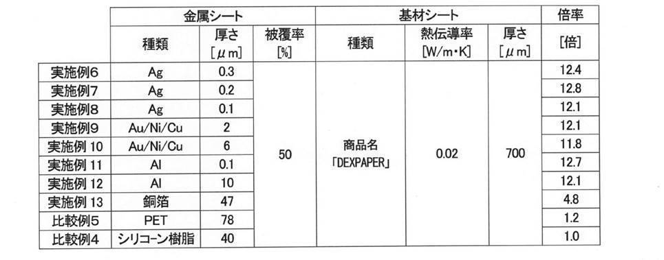
以上の結果から、本発明によれば複雑な形状を設けなくても高温領域と低温領域との間に熱電変換に有効な温度差を生じさせ得ることがわかる。
1 シート本体
10 熱電変換素子
10n n型熱電変換素子
10p p型熱電変換素子
40 基材シート
NH (n型熱電変換素子の)高温領域
NL (n型熱電変換素子の)低温領域
PH (p型熱電変換素子の)高温領域
PL (p型熱電変換素子の)低温領域
50 金属シート
100 熱電変換シート
10 熱電変換素子
10n n型熱電変換素子
10p p型熱電変換素子
40 基材シート
NH (n型熱電変換素子の)高温領域
NL (n型熱電変換素子の)低温領域
PH (p型熱電変換素子の)高温領域
PL (p型熱電変換素子の)低温領域
50 金属シート
100 熱電変換シート
Claims (5)
- 熱電変換に用いられる熱電変換シートであって、
一面側から受熱し、他面側から放熱して前記熱電変換が行われるシート本体と、
前記一面側から前記シート本体に接する基材シートと、
前記他面側から前記シート本体に接する金属シートとを備え、
前記シート本体には該シート本体よりも面積の小さなシート状の熱電変換素子が複数配され、
複数の前記熱電変換素子は直列となるように電気的に接続されて一つの導通経路を構成しており、
複数の前記熱電変換素子のそれぞれには、前記導通経路の一方向に向けて電圧を発生させるべく相対的に高温にされる高温領域と相対的に低温にされる低温領域とが備えられ、
前記金属シートは、前記高温領域を前記他面側から覆うように配され、
前記基材シートは、前記高温領域と前記低温領域との両方を前記一面側から覆うように配されており、
該基材シートの熱伝導率が8W/mK未満である熱電変換シート。 - 前記熱電変換素子が前記金属シートによって覆われている部分の面積割合は、40%以上60%以下である請求項1記載の熱電変換シート。
- 前記基材シートの熱伝導率が1.5W/mK以下である請求項1又は2記載の熱電変換シート。
- 前記金属シートが、アルミニウム箔である請求項1又は2記載の熱電変換シート。
- 前記金属シートが、アルミニウム箔である請求項3記載の熱電変換シート。
Applications Claiming Priority (2)
| Application Number | Priority Date | Filing Date | Title |
|---|---|---|---|
| JP2017-253323 | 2017-12-28 | ||
| JP2017253323A JP2021068716A (ja) | 2017-12-28 | 2017-12-28 | 熱電変換シート |
Publications (1)
| Publication Number | Publication Date |
|---|---|
| WO2019130671A1 true WO2019130671A1 (ja) | 2019-07-04 |
Family
ID=67066925
Family Applications (1)
| Application Number | Title | Priority Date | Filing Date |
|---|---|---|---|
| PCT/JP2018/033919 Ceased WO2019130671A1 (ja) | 2017-12-28 | 2018-09-13 | 熱電変換シート |
Country Status (3)
| Country | Link |
|---|---|
| JP (1) | JP2021068716A (ja) |
| TW (1) | TW201931629A (ja) |
| WO (1) | WO2019130671A1 (ja) |
Cited By (1)
| Publication number | Priority date | Publication date | Assignee | Title |
|---|---|---|---|---|
| JP2022036707A (ja) * | 2020-08-24 | 2022-03-08 | 東洋インキScホールディングス株式会社 | 熱電変換材料及び熱電変換素子 |
Citations (3)
| Publication number | Priority date | Publication date | Assignee | Title |
|---|---|---|---|---|
| JP2000214934A (ja) * | 1998-11-18 | 2000-08-04 | Komatsu Ltd | 温度調節器及びその製造方法 |
| WO2015001899A1 (ja) * | 2013-07-01 | 2015-01-08 | 富士フイルム株式会社 | 熱電変換素子および熱電変換モジュール |
| JP2015142049A (ja) * | 2014-01-29 | 2015-08-03 | 京セラ株式会社 | 太陽電池モジュール |
-
2017
- 2017-12-28 JP JP2017253323A patent/JP2021068716A/ja active Pending
-
2018
- 2018-09-13 WO PCT/JP2018/033919 patent/WO2019130671A1/ja not_active Ceased
- 2018-09-20 TW TW107133107A patent/TW201931629A/zh unknown
Patent Citations (3)
| Publication number | Priority date | Publication date | Assignee | Title |
|---|---|---|---|---|
| JP2000214934A (ja) * | 1998-11-18 | 2000-08-04 | Komatsu Ltd | 温度調節器及びその製造方法 |
| WO2015001899A1 (ja) * | 2013-07-01 | 2015-01-08 | 富士フイルム株式会社 | 熱電変換素子および熱電変換モジュール |
| JP2015142049A (ja) * | 2014-01-29 | 2015-08-03 | 京セラ株式会社 | 太陽電池モジュール |
Cited By (2)
| Publication number | Priority date | Publication date | Assignee | Title |
|---|---|---|---|---|
| JP2022036707A (ja) * | 2020-08-24 | 2022-03-08 | 東洋インキScホールディングス株式会社 | 熱電変換材料及び熱電変換素子 |
| JP7559428B2 (ja) | 2020-08-24 | 2024-10-02 | artience株式会社 | 熱電変換材料及び熱電変換素子 |
Also Published As
| Publication number | Publication date |
|---|---|
| TW201931629A (zh) | 2019-08-01 |
| JP2021068716A (ja) | 2021-04-30 |
Similar Documents
| Publication | Publication Date | Title |
|---|---|---|
| US10243128B2 (en) | Thermoelectric conversion element and thermoelectric conversion module | |
| US10790430B2 (en) | Thermoelectric conversion element and thermoelectric conversion power generation device | |
| JP6256113B2 (ja) | 熱電変換材料含有樹脂組成物からなるフィルムの製造方法および熱電変換素子の製造方法 | |
| US20160260883A1 (en) | Thermoelectric conversion element and method for manufacturing thermoelectric conversion element | |
| TW201535806A (zh) | 熱傳導性接著片、其製造方法及使用此的電子裝置 | |
| US8664509B2 (en) | Thermoelectric apparatus and method of fabricating the same | |
| JP2014204123A (ja) | 印刷回路基板一体型熱電冷却器/加熱器 | |
| WO2018003960A1 (ja) | 熱電変換シート | |
| JP2012124469A (ja) | 熱電素子及び熱電モジュール | |
| JPWO2017038717A1 (ja) | 熱電変換モジュール | |
| WO2019130671A1 (ja) | 熱電変換シート | |
| CN103545440B (zh) | 热电转换结构及使用其的散热结构 | |
| US10347811B2 (en) | Thermoelectric conversion module | |
| US10236431B2 (en) | Thermoelectric conversion element and thermoelectric conversion module | |
| WO2021029590A1 (ko) | 열전장치 | |
| JP7293116B2 (ja) | 熱電焼結体および熱電素子 | |
| US20200006614A1 (en) | Thermoelectric conversion device | |
| KR20180028271A (ko) | 히트 싱크 | |
| JP2022535751A (ja) | 熱電素子 | |
| KR102274205B1 (ko) | 흡습성 고분자를 이용한 방열 구조 및 이를 포함하는 열전 모듈 | |
| JP6500390B2 (ja) | 放熱装置 | |
| KR102551744B1 (ko) | 열전 모듈 | |
| KR102368960B1 (ko) | 열전소자 및 이를 포함하는 열전변환장치 | |
| KR102185537B1 (ko) | 열전소자 | |
| KR102130088B1 (ko) | 열전소자 |
Legal Events
| Date | Code | Title | Description |
|---|---|---|---|
| 121 | Ep: the epo has been informed by wipo that ep was designated in this application |
Ref document number: 18893913 Country of ref document: EP Kind code of ref document: A1 |
|
| NENP | Non-entry into the national phase |
Ref country code: DE |
|
| 122 | Ep: pct application non-entry in european phase |
Ref document number: 18893913 Country of ref document: EP Kind code of ref document: A1 |
|
| NENP | Non-entry into the national phase |
Ref country code: JP |