WO2019130420A1 - 衝撃吸収部材 - Google Patents
衝撃吸収部材 Download PDFInfo
- Publication number
- WO2019130420A1 WO2019130420A1 PCT/JP2017/046611 JP2017046611W WO2019130420A1 WO 2019130420 A1 WO2019130420 A1 WO 2019130420A1 JP 2017046611 W JP2017046611 W JP 2017046611W WO 2019130420 A1 WO2019130420 A1 WO 2019130420A1
- Authority
- WO
- WIPO (PCT)
- Prior art keywords
- portions
- bead
- absorbing member
- pair
- longitudinal direction
- Prior art date
- Legal status (The legal status is an assumption and is not a legal conclusion. Google has not performed a legal analysis and makes no representation as to the accuracy of the status listed.)
- Ceased
Links
Images








Classifications
-
- F—MECHANICAL ENGINEERING; LIGHTING; HEATING; WEAPONS; BLASTING
- F16—ENGINEERING ELEMENTS AND UNITS; GENERAL MEASURES FOR PRODUCING AND MAINTAINING EFFECTIVE FUNCTIONING OF MACHINES OR INSTALLATIONS; THERMAL INSULATION IN GENERAL
- F16F—SPRINGS; SHOCK-ABSORBERS; MEANS FOR DAMPING VIBRATION
- F16F7/00—Vibration-dampers; Shock-absorbers
- F16F7/12—Vibration-dampers; Shock-absorbers using plastic deformation of members
-
- F—MECHANICAL ENGINEERING; LIGHTING; HEATING; WEAPONS; BLASTING
- F16—ENGINEERING ELEMENTS AND UNITS; GENERAL MEASURES FOR PRODUCING AND MAINTAINING EFFECTIVE FUNCTIONING OF MACHINES OR INSTALLATIONS; THERMAL INSULATION IN GENERAL
- F16F—SPRINGS; SHOCK-ABSORBERS; MEANS FOR DAMPING VIBRATION
- F16F7/00—Vibration-dampers; Shock-absorbers
- F16F7/12—Vibration-dampers; Shock-absorbers using plastic deformation of members
- F16F7/123—Deformation involving a bending action, e.g. strap moving through multiple rollers, folding of members
-
- B—PERFORMING OPERATIONS; TRANSPORTING
- B62—LAND VEHICLES FOR TRAVELLING OTHERWISE THAN ON RAILS
- B62D—MOTOR VEHICLES; TRAILERS
- B62D21/00—Understructures, i.e. chassis frame on which a vehicle body may be mounted
- B62D21/15—Understructures, i.e. chassis frame on which a vehicle body may be mounted having impact absorbing means, e.g. a frame designed to permanently or temporarily change shape or dimension upon impact with another body
-
- F—MECHANICAL ENGINEERING; LIGHTING; HEATING; WEAPONS; BLASTING
- F16—ENGINEERING ELEMENTS AND UNITS; GENERAL MEASURES FOR PRODUCING AND MAINTAINING EFFECTIVE FUNCTIONING OF MACHINES OR INSTALLATIONS; THERMAL INSULATION IN GENERAL
- F16F—SPRINGS; SHOCK-ABSORBERS; MEANS FOR DAMPING VIBRATION
- F16F2224/00—Materials; Material properties
- F16F2224/02—Materials; Material properties solids
- F16F2224/0208—Alloys
-
- F—MECHANICAL ENGINEERING; LIGHTING; HEATING; WEAPONS; BLASTING
- F16—ENGINEERING ELEMENTS AND UNITS; GENERAL MEASURES FOR PRODUCING AND MAINTAINING EFFECTIVE FUNCTIONING OF MACHINES OR INSTALLATIONS; THERMAL INSULATION IN GENERAL
- F16F—SPRINGS; SHOCK-ABSORBERS; MEANS FOR DAMPING VIBRATION
- F16F2224/00—Materials; Material properties
- F16F2224/02—Materials; Material properties solids
- F16F2224/0233—Materials; Material properties solids deforming plastically in operation
-
- F—MECHANICAL ENGINEERING; LIGHTING; HEATING; WEAPONS; BLASTING
- F16—ENGINEERING ELEMENTS AND UNITS; GENERAL MEASURES FOR PRODUCING AND MAINTAINING EFFECTIVE FUNCTIONING OF MACHINES OR INSTALLATIONS; THERMAL INSULATION IN GENERAL
- F16F—SPRINGS; SHOCK-ABSORBERS; MEANS FOR DAMPING VIBRATION
- F16F2228/00—Functional characteristics, e.g. variability, frequency-dependence
- F16F2228/001—Specific functional characteristics in numerical form or in the form of equations
- F16F2228/005—Material properties, e.g. moduli
Definitions
- the present invention relates to an impact absorbing member, and more particularly to an impact absorbing member applicable to a frame member of a vehicle.
- a press-formed product obtained by press-forming a steel plate is used for a part of the frame member of the vehicle body.
- a front side member which is an example of a press-formed product, is disposed such that its longitudinal direction is directed from the center of the vehicle body to the front of the vehicle body. Then, when a collision load from the outside of the vehicle is applied, that load is applied along the longitudinal direction of the front side member, and when the magnitude of the load exceeds a limit value, the front side member buckles and deforms. Absorb.
- the thickness is reduced to reduce the weight of the front side member, it will be buckled and deformed by a small load, and the impact can not be sufficiently absorbed.
- the wall thickness is increased, sufficient shock absorbing capacity can be expected, but the weight increases and fuel efficiency can not be improved.
- weight reduction and improvement in collision safety are contradictory characteristics, and there is a demand for a framework member of a vehicle body having both of these characteristics.
- Patent Document 1 discloses a shock absorbing structure.
- the shock absorbing structure includes a shock absorbing member extending from one end to the other, and a plurality of first deformation control portions formed on the shock absorbing member and controlling the deformation of the shock absorbing member by adjusting the strength.
- a plurality of second deformation control units formed on the shock absorption member and controlling the deformation of the shock absorption member by adjusting the strength; and the plurality of first deformation control units include the shock absorption member
- the plurality of second deformation control units are disposed at predetermined intervals along the longitudinal direction, and the plurality of first deformation control units are disposed at a predetermined interval along the longitudinal direction.
- At least one each is arranged between the second deformation control units, and the strength is increased as the plurality of first deformation control units are arranged on the other end side in the longitudinal direction. Include pairs.
- this shock absorbing structure when an impact acts in the longitudinal direction, it can be deformed like a bellows. And, at the time of this deformation, since the shock absorbing member is deformed in order from one end side, the axial compressive deformation of the shock absorbing member is stabilized and the performance of shock absorption is improved.
- Patent Document 2 discloses a method of determining the arrangement of beads.
- the method of determining the arrangement of the beads is a method of determining the arrangement of the beads on the strength member which receives the crushing load, and immediately after applying the crushing load exceeding the peak load point in a state where there is no bead for the strength member.
- the generation state of the buckling waveform obtained in the step is a recess in which the wall surface of the strength member is recessed inward, a recessed wall surface at the generation position of the recess If a bead is disposed and the generation state of the buckling waveform is a convex portion in which the wall surface of the strength member is protruded to the outer side, it is determined to arrange a convex wall bead at the generation position of the convex portion. And a process. According to the method of determining the arrangement of beads, it is said that an optimum bead and its position can be easily determined as compared with the prior art.
- Patent Document 3 discloses a strength member of a car.
- the strength member of this car is a strength member of the car that absorbs impact energy at the time of a collision by providing a bead on a long strength member having a polygonal cross section, and the longitudinal direction of the strength member An elongated bead is formed, and the elongated bead is formed by alternately repeating concave and convex portions continuously with respect to the surface, and the longitudinal bead is formed of concave and convex portions at the time of collision.
- Impact energy is absorbed by causing buckling at the boundary portion, causing the cross section to be deformed alternately at the boundary portion and causing buckling at a substantially central portion between the boundary portion and the adjacent boundary portion.
- the impact energy is absorbed by buckling of the boundary portion between the concave and convex portions of the longitudinal bead and the substantially central portion of the boundary member adjacent to the boundary portion.
- This invention is made in view of the said situation, and makes it a subject to provide the impact-absorbing member excellent in the absorption capability of impact energy.
- a hat-shaped hat-shaped member having a flange and having a cross-sectional shape perpendicular to the longitudinal direction has a hat top, and is joined to the flange and opposed to the hat top
- the length of the first high strength portion along the longitudinal direction is L1 (mm)
- the distance between the hat top portion and the plate-like member is H
- 0.8 ⁇ H ⁇ L1 ⁇ 2.0 ⁇ H may be satisfied.
- the first high-strength portion may be provided on the wall portion along the longitudinal direction. May be included.
- the first high strength portion extends in the longitudinal direction and is in parallel with each other.
- the region adjacent to at least one end of the pair of first bead portions is flat, and at least one of the other pair of first bead portions is flat.
- the area adjacent to the edge is flat.
- regions adjacent to both ends of the pair of first bead portions may be flat.
- the pair of second high strength portions is provided on the wall portion, Provided along the longitudinal direction, each of the one end is adjacent to each of the pair of low strength portions, and the other end has a pair of second bead portions extending to the end portion of the shock absorbing member.
- the shock absorbing member according to any one of the above (4) to (7), the following configuration may be adopted: from the wall surface of the wall portion provided with the first bead portion The height of the first bead portion is d (mm), the width of the first bead portion is w (mm), and the thickness of the wall portion provided with the first bead portion is t (mm) If at least one of d / t ⁇ 2.0 and w ⁇ 10 is satisfied.
- the deformation guiding portion when the first high strength portion receives a load from the outside along the longitudinal direction may be sufficient.
- the deformation guiding portion and the pair of second high strength portions are provided on each of the hat top portion and the plate-like member. It may be provided.
- the following configuration may be adopted: one of the deformation of the hat top and the plate-like member when viewed along the longitudinal direction Among the pair of low strength portions provided in the center position of the first high strength portion provided in the induction portion, and the pair of low strength portions provided in the hat top portion and the other deformation induction portion of the plate-like member, one of the deformation inductions
- the distance between the central portion of the low strength portion located closer to the first high strength portion and the distance along the longitudinal direction to the central portion of the low strength portion is L2 (mm).
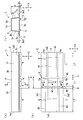
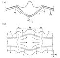
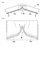
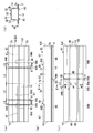
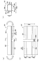
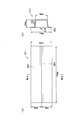
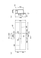
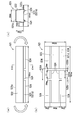
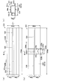
- FIG. 1 It is a figure which shows the impact-absorbing member which concerns on 1st Embodiment of this invention, Comprising: (a) is a side view, (b) is a bottom view, (c) is a sectional view in the AA 'line of (a). Show. It is a side view which shows the state which the said impact-absorbing member received impact energy and was plastically deformed. It is a figure showing the B section in Drawing 2 of the shock absorption member, and (a) is a longitudinal section in the crosswise center position, and (b) is the bottom view which looked at (a) from arrow C .
- the shock absorbing member 1 of the present embodiment has a hollow cross-sectional structure surrounded by four wall portions 1a to 1d. More specifically, the shock absorbing member 1 has a tubular shape elongated in one direction, which is formed of four wall portions 1a to 1d.
- the term "one direction” as used herein refers to the longitudinal direction of the shock absorbing member 1, and in Figs. 1 (a) and 1 (b), the left and right direction (X direction) in the drawing and in (c) the perpendicular direction.
- each of the wall portions 1a to 1d is an end portion 1e1 which receives an impact load from the outside.
- the left side of the drawing shown in FIG. 1A is the one end 1e1, but the shock absorbing member 1 is symmetrical in the left-right direction at the center in the longitudinal direction. And may be configured to receive an impact load.
- the shock absorbing member 1 of the present embodiment can be used, for example, as a front side member or a rear side member which is a frame member of a car.
- a front side member one end side (one end 1e1) of the impact absorbing member 1 in the longitudinal direction is arranged to face the front of the vehicle, and the other end side (the other end 1e2) is a cabin It is arranged to face the side.
- the impact-absorbing member 1 includes a molded body (hat-shaped member) 2 obtained by press-molding a metal plate, and a plate-like member 3 joined to the molded body 2. It consists of two members.
- the X direction indicates the longitudinal direction of the shock absorbing member 1
- the Y direction indicates the width direction of the shock absorbing member 1
- the Z direction is a direction orthogonal to both the X direction and the Y direction.
- the height direction of the shock absorbing member 1 is shown.
- the molded body 2 includes a web portion 2a, a pair of vertical wall portions 2b continuous with both lateral edges of the web portion 2a, and a pair of flange portions 2c continuous with the vertical wall portions 2b.
- the vertical cross-sectional shape is hat-shaped.
- the web portion 2a has a rectangular shape elongated in the one direction.
- Each of the pair of vertical wall portions 2b also has a rectangular shape elongated in the one direction.
- FIG. 1C since the pair of vertical wall portions 2b are integrally connected to the web portion 2a at a slightly wider angle than the right angle, the pair of vertical wall portions 2b is When viewed in a cross section perpendicular to the longitudinal direction, a trapezoidal shape is formed by the combination with the web portion 2a.
- the flange part 2c is integrally formed in the edge of each of a pair of vertical wall part 2b.
- Each of the flanges 2c has a rectangular shape elongated in the one direction and is parallel to each other.
- the impact absorbing member 1 having a hollow cross-sectional structure is formed. Then, the web portion 2 a and the pair of vertical wall portions 2 b of the molded body 2 and the plate-like member 3 form four wall portions 1 a to 1 d constituting the shock absorbing member 1.
- a joining means of each flange part 2c of the molded object 2 and the plate-like member 3 spot joining, linear welding, adhesion
- a metal plate is preferable and it is more preferable to employ a thin steel plate made of high strength steel, an aluminum plate, an aluminum alloy plate or the like.
- a thin steel plate an aluminum plated steel plate or a galvanized steel plate may be used.
- the deformation guiding portion 4 is provided only on the wall portion 1d formed of the plate-like member 3. That is, the other wall portions 1a to 1c have a flat shape in which the deformation guiding portion 4 is not provided.
- the flat shape said here shows the surface shape where the average curvature of an outer surface at least becomes 0.0001 or less, for example.
- region of a flat shape is a non-processed part which has not processed the bead part etc. in it.
- the deformation guiding portion 4 includes a high strength portion 4a (also referred to as a first high strength portion) having a relatively large buckling strength, and a pair of low strength portions 4b having a buckling strength relatively smaller than the high strength portion 4a. It consists of The high strength portion 4a and the pair of low strength portions 4b are arranged in a row without gaps in a row along the longitudinal direction of the wall portion 1d. The high strength portion 4a is disposed so as to be sandwiched between the pair of low strength portions 4b in the longitudinal direction of the wall portion 1d.
- deformation guiding portion 4 is arranged so as to be sandwiched between a pair of high strength portions 7 (also referred to as second high strength portions) in the longitudinal direction of wall portion 1d.
- the low strength portion 4 b is disposed so as to be sandwiched between the high strength portion 4 a and the high strength portion 7, so that the entire area of the wall portion 1 d has a relatively small buckling resistance.
- the high strength portion 4a occupies the area of the substantially central portion in the longitudinal direction of the wall portion 1d in the example of FIG. Moreover, each low strength part 4b occupies the region on both sides of the high strength part 4a.
- the high strength portion 4a is provided with two bead portions 5, and the low strength portion 4b is flat without being provided with the bead portion 5.
- the longitudinal direction of each bead portion 5 is parallel to the longitudinal direction of the wall portion 1 d. Further, each bead portion 5 protrudes from the wall portion 1 d to the outside of the shock absorbing member 1 as shown in FIG. 1 (c). More specifically, when viewed in a cross section perpendicular to the longitudinal direction, that is, in the cross section shown in FIG.
- each bead portion 5 has a triangular corner facing outward. It has a projecting shape and can be formed, for example, by press molding.
- the shape of the bead part 5 in the same cross section may employ
- the low strength portion 4 b is a flat region where the bead portion 5 is not provided.
- the high strength portion 4a is a cross-sectional area having a pair of convex portions formed by each bead portion 5, and is a region sandwiched between the pair of low strength portions 4b. Focusing on the length along the surface from one side edge 3e1 of the plate member 3 to the other side edge 3e2 along the Y direction shown in (b) and (c) of FIG. By providing the portion 5, the length (hereinafter, referred to as an effective width) of the high strength portion 4a which substantially effectively functions along the surface becomes longer than the effective width of the low strength portion 4b.
- the low strength portion 4b and the high strength portion 4a have the same linear dimensions from the side edge 3e1 to the side edge 3e2 in the Y direction when viewed from the front, but the high strength portion 4a has a pair of bead portions 5
- the effective width of the low strength portion 4b is a linear length shown by the side w3.
- the effective width of the high strength portion 4a is longer at the portions of the bead portions 5 at two places than in the case of the linear shape because the portions have beading.
- the buckling resistance of the high strength portion 4a is relatively relative to the buckling resistance of the low strength portion 4b. growing.
- each of the high strength portion 4a and the low strength portion 4b is represented by the sum of the strength F of each side on the member compression side obtained by the following formulas (1) and (2).
- Each side on the side of member compression means a portion where the bead portion 5 is not provided in the cross-sectional shape of the high strength portion 4a and the low strength portion 4b.
- each side on the member compression side is the side w1 between the two bead portions 5 in the case of the high strength portion 4a.
- the side on the member compression side in the case of the low strength portion 4b is a cross-sectional portion of the side w3 along the width direction of the wall portion 1d.
- F is the proof stress of each side
- Ce is the effective width of each side represented by equation (2)
- t1 is the thickness of each side
- sigma y is the yield stress of the material of the respective sides
- E is a Young's modulus of the material forming the sides
- w e is the plate width of each side.
- the bead part 6 different from the bead part 5 is extended to the longitudinal direction both ends of 1 d of wall parts.
- the bead portion 6 also exists in the high strength portion 7 which is a region excluding the deformation guiding portion 4 of the wall portion 1 d. More specifically, a pair of bead portions 6 is provided along the longitudinal direction of the shock absorbing member 1 in each of the high strength portions 7 on both sides of the deformation guiding portion 4.
- the bead portion 6a (6) in one high strength portion 7 is on the same straight line as the bead portion 5a (5) of the high strength portion 4a and the bead portion 6b (6) in the other high strength portion 7 Lined up.
- the bead portion 6c (6) in one high strength portion 7 is also collinear with the bead portion 5b (5) of the high strength portion 4a and the bead portion 6d (6) in the other high strength portion 7 Lined up.
- bead part 5a, 6a, 6b does not need to be on the same straight line
- bead part 5b, 6c, 6d does not need to be on the same straight line.
- the low strength portion 4b of the shock absorbing member 1 extends in the longitudinal direction of the wall portion 1d by the presence of the bead portion 6 that enhances the buckling resistance also in the region (the high strength portion 7) excluding the deformation guiding portion 4.
- the bead portions 5 and 6 are not limited to two regions.
- the bead portion 6 is provided in the high strength portion 7 in order to limit the region of the low strength portion 4 b, but the present invention is not limited to this mode alone, and each low strength portion 4 b is formed
- the region adjacent to the low strength portion 4b may be a region having a relatively high yield stress.
- the plate thickness of the region adjacent to the low strength portion 4b is partially thickened or the like to increase the yield stress of the region, thereby forming the high strength portion 7; The area of the part 4b may be limited.
- the length L1 (mm) of the high strength portion 4a along the longitudinal direction of the wall portion 1d is determined by the length of the bead portion 5 in the longitudinal direction. That is, the length L1 (mm) of the high strength portion 4a is the distance H (mm) between the wall portion 1d provided with the deformation guiding portion 4 and another wall portion 1a disposed facing the wall portion 1d. 0.8 times or more and 2.0 times or less are preferable.
- the distance H (mm) between the wall 1 d and the wall 1 a is taken as the distance between the inner surface (upper surface) of the flat portion of the wall 1 d and the outer surface (upper surface) of the flat portion of the wall 1 a.
- the distance H (mm) is the same as the so-called hat height, and as shown in FIG. 1C, the height from the lower surface of the flange portion 2c to the flat region of the upper surface of the web portion 2a serving as the hat top It is a dimension.
- the low strength portions 4b do not approach each other too much.
- the deformation area at the time of bending deformation is expanded, and the energy absorbing capability at the time of application of an impact load is further enhanced. That is, by setting L1 ⁇ 0.8 ⁇ H, bending deformation of one of the pair of low strength portions 4b and bending deformation of the other are fused to become substantially one-node bending, It can prevent.
- the length C (mm) of each low strength portion 4b along the longitudinal direction of the wall portion 1d is respectively the high strength portion 4a (first high strength portion) and the high strength portion 7 (second high strength portion) It depends on the distance of In the example of FIG. 1, it depends on the distance between the bead portion 5 and the bead portion 6.
- the length C (mm) of each low strength portion 4b along the longitudinal direction of the wall 1d is preferably not more than 0.6 times the distance H (mm).
- the lower limit of C (mm) may be 0.1 ⁇ H (mm) or 0.2 ⁇ H (mm).
- the dimension L7 (mm) of each high strength portion 7 along the longitudinal direction (X direction) is made 0.8 times or more of the distance H (mm). Is preferred.
- the upper limit of L7 is preferably 2.0 times, 3.0 times, or 4.0 times the spacing H (mm).
- the high strength portion 7 may be formed between the low strength portion 4 b and the end of the member.
- the height d (mm) of the bead portion 5 shown in (c) of FIG. 1 is preferably 2.0 times or more the thickness t (mm) of the wall portion 1 d.
- the height d (mm) is the maximum protrusion height from the flat surface of the wall portion 1d as shown in FIG. 1 (c).
- the width w of the bead part 5 is 10 mm or more. This regulation on the shape and size of the bead portion 5 can be applied not only to the case where the cross-sectional shape is a triangle but also to other cross-sectional shapes such as a semicircular shape and a semi-elliptical shape.
- the cross-sectional shape and dimension of the bead portion 6 provided in the high strength portion 7 may be the same as the cross-sectional shape and dimension of the bead portion 5 in the high strength portion 4a, or may be made different if necessary.
- the case where the bead portions 5 and 6 have the same cross-sectional shape and are aligned on the same straight line is described as an example.
- FIG. 2 when a bending moment M caused by application of an impact load is applied to the impact absorbing member 1, two low strength portions 4b separated from each other by sandwiching the high strength portion 4a between It bends and absorbs bending moment M. That is, when viewed macroscopically, it appears that the bending moment M is absorbed at one location in the longitudinal direction of the impact absorbing member 1, but when viewed microscopically, it is dispersed in two low strength portions 4b And bear the bending moment M.
- each of the low strength portions 4b is deformed so as to be recessed inwardly, while the high strength portion 4a is not. It deforms so that it bulges out. More specifically, as shown in FIG. 3A, as a result of bending deformation at each low strength portion 4b, the longitudinal dimension of the high strength portion 4a of the plate member 3 (wall portion 1d) is short. Thus, the high strength portion 4a is compressed toward the longitudinal center. The high strength portion 4a in the compressed state deforms so as to bulge toward the outside of the member because there is no escape place for the meat.
- the high strength portion 4a when the high strength portion 4a is compressed to be deformed to form a bulging portion, the high strength portion 4a functions as a bracing rod, so the deformation is widely spread and impact energy is effectively absorbed. It is possible.
- the flat region for example, a flat portion
- the flat region be surrounded by the pair of bead portions and the pair of low strength portions before deformation. According to this configuration, after the deformation, the flat region can easily form the bulging portion through the above-described process.
- the impact energy can not be sufficiently absorbed.
- the member 100 of (a) and (b) of FIG. 4 is illustrated and demonstrated.
- the member 100 two pairs of bead portions 100a are provided at intervals along the longitudinal direction. That is, the low strength portion 4 b ′ ′ is formed at only one place by providing a flat portion between the two sets of bead portions 100 a as the spacing.
- FIG. 4A when the same bending moment M as that in FIG.
- the bent portion of the low strength portion 4b ′ ′ is subjected to tension because it is deformed inward, and the impact energy can not be sufficiently absorbed.
- the shock absorbing member 1 of the present embodiment the high strength portion 4a is provided between the pair of low strength portions 4b, so that the bent portion is deformed so as to bulge outward, and energy absorption is reduced. As it is received by compression, sufficient proof stress can be exhibited.
- the shock absorbing member 1 In order to understand the effect of the shock absorbing member 1 according to the present embodiment, it is necessary to correctly understand the difference between the meandering deformation and the bellows deformation. That is, as a deformation mode of the shock absorbing member, in addition to the meandering deformation which causes the bending deformation shown in FIG. 2 at a plurality of places, the impact energy is absorbed by the bellows deformation as disclosed in Patent Document 1 etc. There is a mechanism to The bellows deformation is a deformation in which an out-of-plane deformation occurs on all the side surfaces constituting the member, but the center line in the longitudinal direction of the member is hardly bent.
- meandering deformation refers to deformation in which out-of-plane deformation occurs mainly on one of the side surfaces constituting the member and in which the center line in the longitudinal direction of the member is also bent.
- the deformation mode is a meandering deformation by arranging the pair of low strength portions 4b with the high strength portion 4a interposed therebetween. It is controlled to become. By performing such control, it is possible to stably absorb impact energy even if the disturbance as described above occurs.
- the impact absorbing member 1 according to the present embodiment described above will be summarized below.
- the impact absorbing member 1 of the present embodiment has a flange portion 2 c and a hat-shaped molded body (hat-shaped member) 2 having a web portion 2 a which has a cross-sectional shape perpendicular to the longitudinal direction and which becomes a hat top And a plate-like member 3 joined to the portion 2c and facing the web portion 2a.
- the deformation guiding portion 4 is provided on the wall portion 1 d which is the plate-like member 3 of the web portion 2 a and the plate-like member 3.
- the deformation guiding portion 4 has a relatively high buckling strength in the wall portion 1d (first high strength portion) 4a, and has a relatively low buckling resistance and is viewed along the longitudinal direction. And a pair of low strength portions 4b disposed on both sides of the high strength portion 4a. Furthermore, when viewed along the longitudinal direction, the shock absorbing member 1 is disposed on both sides of the deformation guiding portion 4 so as to be adjacent to each of the pair of low strength portions 4b, and for each low strength portion 4b.
- a pair of high strength parts (second high strength parts) 7 having a relatively high buckling strength;
- the bending position and the bending direction when receiving impact energy can be arbitrarily set according to the position of the deformation guiding portion 4 in the longitudinal direction. Further, since the bending deformation at this time occurs in each of the pair of low strength portions 4b separated from each other by the high strength portion 4a, the bending deformation in one place in the prior art is dispersed into two bending deformations. I can do it. As a result, the area to be bent and deformed can be expanded in the longitudinal direction of the wall portion 1d, so it is possible to increase the amount of impact energy absorbed. Therefore, according to the shock absorbing member 1, it is possible to exhibit a high absorbing ability of impact energy while making bending deformation as expected when an impact is applied.
- the deformation guiding portion 4 is provided on the wall portion 1d (plate-like member 3) of the wall portions 1a to 1d. According to this configuration, since the wall portion 1d integrally formed with the pair of flange portions 2c has a relatively high buckling resistance compared to the other, the deformation guiding portion 4 is provided to bend and deform the wall portion 1d. It is possible to further increase the amount of energy absorption.
- the impact absorbing member 1 has a length L1 (mm) along the longitudinal direction of the high strength portion 4a and a distance H (mm) between the web portion 2a at the top of the hat and the plate-like member 3 In addition, the relationship of 0.8 ⁇ H ⁇ L1 ⁇ 2.0 ⁇ H is satisfied. According to the shock absorbing member 1, since the pair of low strength portions 4b can be reliably separated, it is possible to disperse and cause bending deformation occurring in the respective low strength portions 4b without mutually interfering. become.
- the impact absorbing member 1 has a length C (mm) along the longitudinal direction of the pair of low strength portions 4 b and a distance H between the web portion 2 a and the plate-like member 3 H (mm). , C ⁇ 0.6 ⁇ H. According to the above-mentioned impact-absorbing member 1, it becomes possible to achieve both the limitation of the bending deformation position and the reliable bending deformation at the same deformation position.
- the high strength portion 4 a has a bead portion 5 (first bead portion) provided on the plate-like member 3 along the longitudinal direction.
- the bead portion 5 having an appropriate shape and size can be formed at an appropriate position by a simple means such as pressing, so that the range of reinforcement and the degree of reinforcement by the bead portion 5 are accurately set. It is possible to
- the high strength portion 4a has a pair of bead portions 5a and 5b extending in the longitudinal direction and parallel to each other.
- the low strength portions 4b which are areas adjacent to one end (left side in the drawing) of both of the pair of bead portions 5a and 5b are flat.
- the low strength portion 4b which is a region adjacent to the other end (right side in the drawing) of both of the pair of bead portions 5a and 5b is also flat.
- the pair of low strength portions 4b can be easily formed.
- the low strength portion 4b adjacent to both of the pair of bead portions 5a and 5b is flat.
- the relative strength at each position of the pair of low strength portions 4b may be weaker than at other positions, so other embodiments described later, etc.
- configurations other than the above embodiment may be adopted. Specifically, on one end side of the pair of bead portions 5a and 5b, not the both but only one adjacent low strength portion 4b may be flat. Similarly, on the other end side of the pair of bead portions 5a and 5b, not the both but only one adjacent low strength portion 4b may be flat.
- the pair of high strength portions 7 is provided on the wall portion 1 d of the shock absorbing member 1 along the longitudinal direction.
- the pair of high strength portions 7 includes bead portions (second bead portions) 6a to 6d, one end of each of which is adjacent to the pair of low strength portions 4b.
- one of the pair of high strength portions 7 is a bead portion 6b, 6d extended along the longitudinal direction between the one end portion 1e1 of the shock absorbing member 1 and one of the pair of low strength portions 4b.
- Equipped with The other of the pair of high strength portions 7 is provided with bead portions 6a and 6c extending along the longitudinal direction between the other end portion 1e2 of the impact absorbing member 1 and the other of the pair of low strength portions 4b. According to the shock absorbing member 1, the position and the length of the low strength portion 4 b can be easily set between the bead portions 5 and 6.
- the height of the bead portion 5 from the wall surface of the wall portion 1d provided with the bead portion 5 is d (mm), and the width of the bead portion 5 is w (mm)
- d (mm) the thickness of the wall 1 d provided with the bead 5
- w the width of the bead portion 5
- both d / t ⁇ 2.0 and w ⁇ 10 are satisfied.
- the shock absorbing member 1 the pair of low strength portions 4b can be bent and deformed while keeping the distance therebetween. Therefore, it is possible to more reliably absorb impact energy. This effect can be obtained by satisfying one of d / t ⁇ 2.0 and w ⁇ 10, but a more reliable effect can be expected by satisfying both of them.
- the high strength portion 4a bulges outward in the thickness direction of the wall portion 1d provided with the deformation guiding portion 4 when a load is applied from the outside along the longitudinal direction. It has become a bulging part. According to the shock absorbing member 1, the high strength portion 4a is deformed as a bulging portion at the time of the bending deformation, and energy absorption is received by compression, so that sufficient proof stress can be exhibited. Therefore, it is possible to absorb impact energy more effectively than the conventional structure which performs bending deformation at one place or bellows deformation.
- the present invention is based only on this composition.
- the number of the bead portions 5 and 6 is not limited to one, and may be one or three or more. Furthermore, the numbers of the bead portions 5 and 6 may be different from each other. For example, the number of bead portions 5 provided in the high strength portion 4a may be two, and the number of bead portions 6 provided in the high strength portion 7 may be one, or vice versa.
- derivation part 4 was provided in the wall part 1d, if this invention provides not only this structure but the deformation
- the deformation guiding portion 4 is provided on a plurality of wall portions, for example, if the shock absorbing member 1 is to be bent in one direction, the deformation guiding portions 4 are respectively formed on the two wall portions facing each other in the bending direction. May be provided.
- the other wall portions not provided with the deformation guiding portion 4 are preferably flat (for example, flat).
- derivation part 4 is not limited only to the longitudinal direction center position of wall part 1d, You may provide in the one side or the other side of the longitudinal direction.
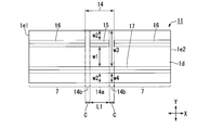
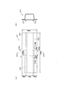
- FIG. 5 is a diagram corresponding to (b) of FIG.
- the deformation guiding portion 14 is provided only on the wall portion 1 d formed of the plate-like member 3 among the plurality of wall portions 1 a to 1 d.
- the deformation guiding portion 14 includes a high strength portion 14a (also referred to as a first high strength portion) having a relatively high buckling resistance, and a pair of low strength portions 14b having a buckling resistance relatively lower than the high strength portion 14a. And consists of The high strength portion 14a and the low strength portion 14b are arranged along the longitudinal direction of the wall portion 1d.
- the high strength portion 14a is disposed between the pair of low strength portions 14b in the longitudinal direction of the wall portion 1d.
- the deformation guiding portion 14 is disposed so as to be sandwiched between the pair of high strength portions 7 (also referred to as a second high strength portion) in the longitudinal direction of the wall portion 1d.
- the low strength portion 14 b is disposed so as to be sandwiched between the high strength portion 14 a and the high strength portion 7, so that the entire area of the wall portion 1 d becomes a region where the buckling resistance is relatively small.
- the high strength portion 14a occupies a region substantially at the center in the longitudinal direction of the wall portion 1d.
- the low strength portion 14b occupies two regions adjacent to both sides of the high strength portion 14a without a gap.
- the bead portion 17 is present in the region occupied by the low strength portion 14b.
- another bead portion 16 is provided on both sides in the longitudinal direction of the bead portion 15 at intervals.
- the bead portion 15 and each bead portion 16 are separated from each other along the longitudinal direction, and an unmachined portion is formed between the bead portions 15 and 16. Further, the bead portions 15 and 16 and the bead portion 17 are parallel to each other.
- a central portion in which two bead portions 15 and 17 are arranged parallel to each other is taken as a high strength portion 14a.
- two regions including flat portions (for example, unprocessed portions) adjacent to both ends of the bead portion 15 and extending along the Y direction in FIG. 5 are a pair of low strength portions 14b.
- these low strength portions 14b although the bead portions 15 and 16 do not exist, the bead portion 17 exists.
- the bead portions 15 to 17 project outward of the shock absorbing member 11 from the outer surface of the wall portion 1d.
- the shapes of the bead portions 15 to 17 in a cross section perpendicular to the longitudinal direction of the wall portion 1 d are the same as the bead portions 5 and 6 described in the first embodiment.
- the effective width of the high strength portion 14a in which the two bead portions 15 and 17 are provided is larger than the effective width of the low strength portion 14b in which only one bead portion 17 is provided. As a result, the buckling resistance of the high strength portion 14a is relatively larger than that of the low strength portion 14b.
- the buckling strength of the high strength portion 14a and the low strength portion 14b is represented by the sum of the strengths F of the respective compression side of the member obtained by the above equation (1), as in the first embodiment.
- the side in the high strength portion 14a is the side w1 in the cross sectional shape between the two bead portions 15 and 17, and 2 in the cross sectional shape from the bead portions 15 and 17 to both end portions in the width direction of the wall portion 1d. There are three sides in total with the side w2.
- the sides in the low strength portion 14 b are two sides w 3 and w 4 in the cross-sectional shape on both sides in the width direction of the bead portion 17.
- the bead parts 16 and 17 are extended to the longitudinal direction both ends of 1 d of wall parts.
- both of the bead portions 16 and 17 are continuously present in the region (the high strength portion 7) of the wall portion 1 d excluding the deformation guiding portion 14.
- Each low strength portion 14b in which the bead portion 17 is present but the bead portion 16 is not present is a region in which the buckling strength is relatively weakened compared to the two adjacent in the longitudinal direction.
- the deformation guiding portion 14 when an impact load is applied to the one end portion 1e1 of the impact absorbing member 11, the deformation guiding portion 14 is bent and deformed as in the case of the first embodiment.
- energy absorption of impact load is performed.
- the bead portion 16 is provided in the region (high strength portion 7) other than the deformation guiding portion 14; It is not limited only to the configuration. As a configuration for enhancing the buckling resistance of the high strength portion 7 other than providing the bead portions 16 and 17, for example, it can be considered to relatively thicken the plate thickness of the high strength portion 7 of the wall portion 1d.
- the dimensions (L1, C) of the high strength portion 14a and the low strength portion 14b may be the same as in the first embodiment.
- the length L1 of the high strength portion 14a along the longitudinal direction is determined by the length of the bead portion 15 in the longitudinal direction.
- the length C of the low strength portion 14 b along the longitudinal direction of the wall portion 1 d is determined by the distance between the bead portion 15 and the bead portion 16.
- the height and width of the bead portions 16 and 17 may be the same as or different from the height and width of the bead portion 15 in the high strength portion 14a.
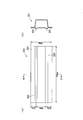
- FIG. 6 is a diagram corresponding to (b) of FIG.
- differences from the first embodiment will be mainly described, and the other configurations are the same as the first embodiment, and the redundant description will be omitted.
- the deformation guiding portion 24 is provided on the wall portion 1d formed of a plate-like member.
- the deformation guiding portion 24 includes a high strength portion 24a (also referred to as a first high strength portion) having a relatively high buckling resistance, and a pair of low strength portions 24b having a buckling resistance relatively lower than the high strength portion 24a. It consists of The high strength portion 24a and the low strength portion 24b are arranged along the longitudinal direction of the wall portion 1d. The high strength portion 24a is disposed between the pair of low strength portions 24b in the longitudinal direction of the wall portion 1d.
- the deformation guiding portion 24 is disposed so as to be sandwiched between the pair of high strength portions 7 (also referred to as a second high strength portion) in the longitudinal direction of the wall portion 1d.
- the low strength portion 24 b is disposed so as to be sandwiched between the high strength portion 24 a and the high strength portion 7, so that the entire area of the wall portion 1 d becomes a region where the buckling resistance is relatively small.
- the high strength portion 24a occupies a region substantially in the center in the longitudinal direction of the wall portion 1d.
- the low strength portion 24b occupies a region adjacent to both sides of the high strength portion 24a.
- two bead portions 25 and 26 parallel to each other are present in the high strength portion 24a.
- only one of the bead portion 25 and the bead portion 26 is present in each low strength portion 24 b.
- another bead portion 27 is present on the other end side in the longitudinal direction of the bead portion 25, and another bead portion 28 is present on one end side of the bead portion 26 in the longitudinal direction.
- the bead portion 25 provided from the longitudinal end (one end 1e1) side of the wall portion 1d to the central portion in the longitudinal direction, and the other end in the longitudinal direction (the other end)
- a bead portion 26 is provided from the 1e2 side to the longitudinal central portion, and other bead portions 27 and 28 on the extension of the bead portions 25 and 26 are provided.
- the bead portion 25 and the bead portion 27 are separated from each other, and a flat, unmachined portion is formed between the bead portions 25 and 27.
- the bead portion 26 and the bead portion 28 are separated from each other, and a flat and unmachined portion is formed between the bead portions 26 and 28.
- the bead portion 25 and the bead portion 27 are on the same straight line, and similarly, the bead portion 26 and the bead portion 28 are also on the same straight line.
- the bead portion 25 and the bead portion 27 and the bead portion 26 and the bead portion 28 are parallel to each other.
- the bead portions 25 and 26 have portions aligned in parallel with each other at the center in the longitudinal direction of the wall portion 1 d.
- the central portion in which the bead portions 25 and 26 are arranged in parallel is the high strength portion 24a.
- One region including the unprocessed portion between the bead portion 25 and the bead portion 27 and extending along the Y direction in FIG. 6 is one of the pair of low strength portions 24 b.
- each bead 25 to 28 protrudes from the wall surface of the wall 1 d to the outside of the shock absorbing member 21.
- the shape of each bead 25 to 28 in a cross section perpendicular to the longitudinal direction of the wall 1 d is the same as that of the beads 5 and 6 described in the first embodiment.
- the effective width of the high strength portion 24a in which the two bead portions 25 and 26 exist is compared with the effective width of the low strength portion 24b in which only one of the bead portion 25 and the bead portion 26 exists. large.
- the buckling resistance of the high strength portion 24a is relatively higher than the buckling resistance of the low strength portion 24b.
- the buckling strength of the high strength portion 24a and the low strength portion 24b is represented by the sum of the strengths F of the respective compression side of the member obtained by the equation (1), as in the case of the first embodiment.
- the side in the high strength portion 24a is one side w1 in the cross sectional shape between the two bead portions 25 and 26, and 2 in the cross sectional shape from the bead portions 25 and 26 to the end in the width direction of the wall portion 1d. There are three sides in total with the side w2.
- the sides in the low strength portion 24 b are two sides w 3 and w 4 in the cross-sectional shape on both sides in the width direction of the bead portion 25 or 26.
- the bead portions 25 to 28 respectively extend to both ends in the longitudinal direction of the wall portion 1 d.
- the bead portions 25 to 28 exist not only in the deformation guiding portion 24 but also in the region (high strength portion 7) excluding the deformation guiding portion 24.
- the low strength portion 24b of the shock absorbing member 21 is a single bead portion. It is limited to the area where only 25 (or 26) is present.
- the bead portions 25 to 28 are provided in the high strength portion 7 other than the deformation guiding portion 24 in order to limit the region of the low strength portion 24b, but the present invention is not limited to this configuration.
- the buckling resistance of the high strength portion 7 other than the deformation guiding portion 24 is adjusted by means other than providing the bead portions 25 to 28, for example, by partially increasing the plate thickness or raising the yield stress, thereby reducing the The area of the strength portion 24b may be limited.
- the dimensions (L 1, C) of the high strength portion 24 a and the low strength portion 24 b may be the same as in the first embodiment.
- the length L1 along the longitudinal direction of the wall portion 1d of the high strength portion 24a is determined by the length in which the bead portions 25 and 26 are arranged parallel to each other.
- the length C of the low strength portion 24b along the longitudinal direction of the wall portion 1d is determined by the distance between the bead 25 and the bead 27 and the distance between the bead 26 and the bead 28.
- the heights and widths of the bead portions 25 to 28 may be the same size as each other, or may be different sizes from each other.
- the shock absorbing member 21 of the present embodiment is provided with a pair of the bead portions 25 and 27 and a pair of the bead portions 26 and 28. And the group of bead parts 25 and 27 which is one of these pairs is continuously formed except for the part by the side of one side among a pair of low strength parts 24b. Furthermore, the pair of bead portions 26 and 28 on the other side of the pair is continuously formed except for the portion on the other side of the pair of low strength portions 24 b. According to this configuration, when an impact load is applied to the one end 1e1 of the impact absorbing member 21 of FIG. 6, the deformation guiding portion 24 is bent and deformed as in the case of the first embodiment.
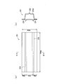
- the shock absorbing member 61 of the present embodiment is provided with a plurality of (three in the illustrated example) deformation guiding portions 64A, 64B, 64C. That is, the deformation guiding portion 64A is provided on the wall portion 1d configured of the plate-like member 3, and the two deformation guiding portions 64B and 64C are provided on the wall portion 1a formed of the web portion 2a of the molded body 2. Respective deformation guiding portions 64A to 64C are spaced apart from each other along the longitudinal direction of shock absorbing member 61.
- the deformation guiding portions 64A to 64C are respectively a high strength portion 64a (also referred to as a first high strength portion) having a relatively large buckling resistance and a pair of low strengths having a relatively small buckling resistance compared to the high strength portion 64a. It comprises the strength portion 64b.
- the high strength portion 64a and the low strength portion 64b are arranged along the longitudinal direction of each of the wall portions 1a and 1d.
- the high strength portion 64a is disposed between the pair of low strength portions 64b in the longitudinal direction of the wall portions 1a and 1d.
- each of deformation guiding portions 64A to 64C is arranged to be sandwiched by high strength portions 64d (also referred to as second high strength portions) in the longitudinal direction of impact absorbing member 61.
- the low strength portion 64b is disposed so as to be sandwiched between the high strength portion 64a and the high strength portion 64d, so that in the wall portions 1a and 1d, relative to the high strength portions 64a and 64d which are other regions, respectively. In the region where the buckling strength is small.
- a portion having a relatively high buckling resistance is a high strength portion 64a
- a portion having a relatively low buckling resistance is a low strength portion 64b.
- a high strength portion 64a is provided in a substantially central region in the longitudinal direction.
- two high strength portions 64a are provided in both side regions in the longitudinal direction of the wall portion 1a.
- each low strength portion 64b is provided in a region adjacent to the high strength portion 64a.
- the low strength portion 64b is left as a flat unprocessed portion in which the bead portion is not provided.
- One bead portion 65 is provided in the high strength portion 64a of the wall portion 1a, and two bead portions 65 are provided in parallel with each other in the high strength portion 64a of the wall portion 1d. Further, two pairs of bead portions 66 are provided on the wall portion 1d. One of the two sets extends between one end of the pair of low strength portions 64b and the one end portion 1e1. The other of the two pairs extends between the other of the pair of low strength portions 64b and the other end 1e2.
- a bead 67 extending to reach the one end 1e1 adjacent to one of the pair of low strength portions 64b in the deformation guiding portion 64B; and a pair of low strength portions 64b in the deformation guiding portion 64B A bead portion 67 extending in the longitudinal direction of the wall portion 1a so as to be adjacent to both the other and one of the pair of low strength portions 64b of the deformation guiding portion 64C; a pair of low strength portions of the deformation guiding portion 64C A bead 67 is provided adjacent to the other of the 64 b and extending to the other end 1 e 2.
- the bead portions 65 and the bead portions 66, or the bead portions 65 and the bead portions 67, are arranged side by side on extended lines corresponding to each other with the low strength portions 64b interposed therebetween.
- the relative strength of the high strength portion 64a provided on the wall portion 1a is shorter than that of the high strength portion 64a provided on the wall portion 1d.
- the low strength portion 64b has the same length in both the wall portion 1a and the wall portion 1d.
- each of the bead portions 65 to 67 is parallel to the longitudinal direction of the wall portions 1a and 1d. Furthermore, as shown in (d) of FIG. 7, the bead portion 65 protrudes from the wall portions 1 a and 1 d toward the outside of the shock absorbing member 61.
- the bead portions 66 and 67 also have the same cross-sectional shape.
- the low strength portion 64 b is a region having a cross-sectional shape in which none of the bead portions 65, 66 and 67 is provided.
- the high strength portion 64a is a region having a cross-sectional shape in which the bead portion 65 is provided, and is a region sandwiched between the pair of low strength portions 64b.
- the effective width of the high strength portion 64a is larger than the effective width of the low strength portion 64b.
- the buckling resistance of the high strength portion 64a is relatively larger than the buckling resistance of the low strength portion 64b.
- the buckling strength of the high strength portion 64a and the low strength portion 64b is represented by the sum of the strengths F of the respective compression side of the member obtained by the equation (1), as in the first embodiment. It is preferable that there is a difference of 10% or more between the buckling resistance of the deformation guiding portion 64A in the wall portion 1d and the total buckling resistance of the two deformation guiding portions 64B and 64C in the wall portion 1a. By providing such a difference, the bending direction of the impact absorbing member 61 can be determined.
- the side when obtaining the proof stress F of the high strength portion 64a in the deformation induction portion 64A is one side w1 between the two bead portions 65, and from each bead portion 65 to both ends in the width direction of the wall portion 1d. There are a total of three sides with the two sides w2 in the cross-sectional shape.
- the side in the low strength portion 64b is one side w5 along the width direction of the wall portion 1a or 1d.
- the wall 1a is bent and deformed so as to be inside the bending at the deformation guiding portion 64B close to the one end 1e1.
- the wall portion 1d is bent and deformed so as to be inside of the bending.
- the wall portion 1a is bent and deformed so as to be inside of the bending.
- the deformation at this time is bent so as to be convex downward in the deformation guiding portion 64B in the side view shown in (b) of FIG. 7 and is bent so as to be convex upward in the deformation guiding portion 64A.
- the portion 64C is bent downward to be convex. Therefore, the impact absorbing member 61 deforms so as to shorten its overall length while meandering as a whole.
- the deformation guiding parts 64A to 64C are provided on the pair of wall parts 1a and 1d facing each other, and the positions of the deformation guiding parts 64A to 64C are It arrange
- the impact absorbing member 61 can be bent and deformed in directions opposite to each other at a plurality of locations. That is, the impact absorbing member 61 can be deformed in a meandering manner, not in a bellows-like manner along the axial direction.
- the energy absorption amount of impact load can be stably secured even when there is a disturbance as in the case where the load input direction changes.
- impact energy is received while forming the bulging portion when the deformation guiding portion 64A is bent, it is possible to exhibit higher impact energy absorbing capability.
- the deformation guiding parts may be provided on each of the wall parts 1a and 1d facing each other.
- deformation guiding portions may be provided on mutually adjacent wall portions as in the wall portions 1d and 1b. In this case, when viewed along the longitudinal direction, the bending direction at the time of deformation of the shock absorbing member can be alternately bent in directions different from each other by adjacent ones.
- the shock absorbing member 61 according to the present embodiment described above will be summarized below.
- the impact absorbing member 61 of the present embodiment has a tubular shape elongated in one direction, which is formed by the plurality of wall portions 1a to 1d.
- Deformation guiding portions 64A to 64C are provided on the mutually separated pair of wall portions 1a to 1d of the plurality of wall portions 1a to 1d, respectively, at portions separated from each other when viewed along the one direction. ing. Further, each of the deformation guiding portions 64A to 64C and the high strength portion 64a having a relatively high buckling resistance are relatively low in the buckling resistance and viewed along the one direction. And a pair of low strength portions 64b disposed on both sides sandwiching 64a.
- the wall portion 1d is formed with a high strength portion (second high strength portion) 64d having a pair of bead portions 66 adjacent to the low strength portions 64b of the deformation guiding portion 64A. Further, a high strength portion (second high strength portion) 64d having a bead portion 67 adjacent to each low strength portion 64b of the deformation guiding portions 64B and 64C is formed on the wall portion 1a.
- the bending position and bending direction when impact energy is received can be arbitrarily set according to the positions of deformation guiding portions 64A to 64C in the longitudinal direction. Further, since the bending deformation at this time is performed independently at each position of the deformation guiding parts 64A to 64C, it becomes possible to disperse and absorb impact energy. Moreover, at each position of the deformation guiding portions 64A to 64C, bending deformation is caused in each of the pair of low strength portions 64b separated from each other by the high strength portions 64a, so that bending deformation was conventionally performed at one place. Can be dispersed into two bending deformations.
- the area to be bent and deformed can be expanded in the longitudinal direction of the wall portion 1d, so it is possible to increase the amount of impact energy absorbed. Therefore, according to the shock absorbing member 61, it is possible to exhibit a high absorbing ability of impact energy while making bending deformation as expected when an impact is applied.
- the wall portion 1 d which is one of the plurality of wall portions 1 a to 1 d is a plate-like member, and the wall portions 1 a to 1 c which are the other are the plate-like members.
- the molded body 2 is a hat-shaped member having a pair of flanges 2c joined to each other.
- the deformation guiding part 64A to 64C is provided on the wall part 1d, and the other deformation guiding parts 64B and 64C are the wall parts 1a facing the plate-like member of the hat-shaped members.
- the shock absorbing member 61 of the present embodiment is provided with one deformation guiding portion 64A provided on the wall portion 1d which is one of the pair of wall portions 1a and 1d facing each other.
- the other deformation guiding portions 64B and 64C are provided on the other wall portion 1a and are adjacent to each other when viewed along the one direction with respect to one deformation guiding portion 64A.
- a central position of the high strength portion 64a provided in one of the deformation guiding portions 64A and a pair of low strength portions provided in the other deformation guiding portions 64B and 64C is L2 (mm)
- L2 ⁇ 6.0 ⁇ H is satisfied. Is preferred.
- the deformation / induction portions 64A to 64C can be bent and deformed continuously, so that it is possible to effectively absorb impact energy. Therefore, it is possible to effectively absorb impact energy while meanderingly deforming the impact absorbing member 61 as set.
- the shock absorbing member 61 has a distance L3 between the intermediate positions of the pair of low strength portions 64b when viewed along the one direction. mm), and the distance between the wall portions 1d and 1a provided with each of the deformation induction portions 64A to 64C is H (mm), satisfying 0.8 ⁇ H ⁇ L3 ⁇ 2.0 ⁇ H Is preferred.
- the shock absorbing member 61 has a length along the one direction of each of the pair of low strength portions 64b as C (mm). It is preferable to satisfy C ⁇ 0.6 ⁇ H, where H (mm) is the distance between the wall portions 1 d and 1 a provided with each of 64C. According to the above configuration, by setting C ⁇ 0.6 ⁇ H, it is possible to appropriately weaken the buckling resistance at each position of each low strength portion 64 b and to reliably cause bending deformation.
- the high strength portions 64a of the deformation guiding portions 64A to 64C each have a bead portion 65 extending along the one direction.
- the bead portion 65 having an appropriate shape and size can be formed at an appropriate position by a simple means such as press processing, so that the reinforcement range and reinforcement degree by the bead portion 65 can be accurately set. It becomes possible.
- the bead part 66, 67 is also formed in the impact-absorbing member 61 of this embodiment. According to this configuration, it is possible to accurately set the position and the length of the low strength portion 64b by the distance between the bead portion 65 and the bead portion 66 and the distance between the bead portion 65 and the bead portion 67.
- the high strength portion 64a of the deformation guiding portion 64A forms a bulging portion that is deformed outward when being subjected to a load from the outside. According to the shock absorbing member 61, at the time of the bending deformation, the high strength portion 64a of the deformation guiding portion 64A is deformed as a bulging portion and energy absorption is received as compression, so that sufficient proof stress can be exhibited. Therefore, it is possible to absorb impact energy more effectively than a conventional structure in which bending deformation or bellows deformation occurs at one place.
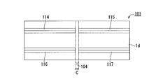
- the shock absorbing member 101 shown in FIG. 8 is a comparative example in the case where one low strength portion 104 is provided at the center in the longitudinal direction. That is, four bead portions 114 to 117 are provided on the wall portion 1d of the shock absorbing member 101 shown in FIG. Bead portions 114 and 116 exist parallel to one another, and bead portions 115 and 117 exist parallel to one another. Further, the bead portion 115 exists on the longitudinal extension of the bead portion 114, and the bead portion 117 exists on the longitudinal extension of the bead portion 116.
- the portion between the bead portions 114 and 115 is a flat unprocessed portion as it is the wall portion 1d.
- the portion between the bead portions 116 and 117 is also a flat unprocessed portion as it is the wall portion 1d.
- the portion where the bead portions 114 to 117 are not provided is the low strength portion 104. Since the low strength portion 104 is not provided with a bead portion, the effective width is smaller than other portions. As a result, the low strength portion 104 has a smaller buckling resistance than the other portions.
- the width C of the low strength portion 104 is 30 mm.
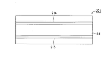
- the impact-absorbing member 201 shown in FIG. 9 is a comparative example when there is no low strength part. That is, in the wall portion 1d of the shock absorbing member 201 shown in FIG. 9, two bead portions 214 and 215 are provided in parallel to each other. In the shock absorbing member shown in FIG. 9, since the bead portions 214 and 215 are continuously provided over the entire length in the longitudinal direction of the wall portion 1d, there is no low strength portion consisting of a non-processed portion.
- the impact absorbing members 1, 11 and 21 of the invention examples and the impact absorbing members 101 and 201 of the comparative example having the configuration described above were manufactured using a high strength steel plate of tensile strength 980 MPa class. Then, as shown by the outlined arrows in FIG. 10, moment is applied to both ends in the longitudinal direction of each of the impact absorbing members 1, 11, 21, 101, 201 so that the wall 1d side is inside the bend, and the bending angle is The absorbed energy was measured when it was bent to 20 °. The measurement results are shown in Table 1 below.
- each part dimension of each impact-absorbing member 1 (sample number 1), 11 (sample number 2), 21 (sample number 3), 101 (sample number 4), 201 (sample number 5) is as follows, respectively. .
- the impact absorbing members 1 (sample No. 1), 11 (sample No. 2) and 21 (sample No. 3) of the invention examples are the impact absorbing members 101 (sample No. 4) and 201 which are comparative examples. It was found that the absorbed energy increased significantly as compared with (Sample No. 5).
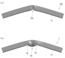
- FIG. 11 shows a schematic view of impact absorbing members 1 (sample No. 1) and 101 (sample No. 4) after the bending test.
- FIG. 11A is a schematic side view of the impact-absorbing member 101 as a comparative example shown in FIG. 8 after a bending test.
- FIG. 11B is a schematic side view of the impact-absorbing member 1 as an example of the invention shown in FIG. 1 after a bending test.
- the impact absorbing members 1, 11 and 21 which are the invention examples described above can be bent and deformed so that the wall portion 1d provided with the deformation guiding portions 4, 14 and 24 is bent inward when an impact load is applied.
- the At the time of bending deformation bending deformation occurs in the pair of low strength portions 4b, 14b, 24b, and the high strength portions 4a, 14a, 24a are further present between the pair of low strength portions 4b, 14b, 24b.
- the places where deformation occurred were dispersed in the longitudinal direction. As a result, the deformation area expands in the longitudinal direction of the wall portion 1d, and bending deformation occurs in a relatively wide area. As a result, the amount of energy absorbed when an impact load was applied could be increased. Further, since the deformation guiding portions 4, 14, 24 can be provided at arbitrary places of the wall portion 1d, the design for shock absorption can be easily performed.
- the dimensions and arrangement of the high strength portions 4a, 14a, 24a can be adjusted by adjusting the length of the bead portions 5, 6, 15-17, 25-28 and arranging. , could be easily designed for shock absorption.
- the length along the longitudinal direction of the wall portion 1d of the high strength portions 4a, 14a, 24a is 0.8 times or more and 2.0 times or less the distance between the opposing wall portions 1d, 1a (hat height H) In this range, the pair of low strength portions 4b and 4b (or the pair of low strength portions 14b and 14b, or the pair of low strength portions 24b and 24b) can be reliably separated.
- the bending deformations occurring at the low strength portions 4b, 14b and 24b can be dispersed and caused without mutual interference.
- the length C of the low strength portions 4b, 14b and 24b is 30 mm or less (C ⁇ 0.6 ⁇ H)
- the place where bending deformation occurs can be limited to a specific place, thereby the high strength portion 4a , 14a, 24a could enhance the dispersion function of the bending deformation point more.
- the heights of the bead portions 5, 6, 15 to 17 and 25 to 28 may be 2.0 times or more of the thickness of the wall portion 1d and the width may be 10 mm or more. And it was effective in making the difference of the buckling strength in the low strength part 4b, 14b, 24b significant.
- FIGS. 12, 14, 15, and 17 show comparative examples
- FIGS. 13 and 16 show inventive examples.
- An impact absorbing member 301 shown in FIG. 12 includes a formed body (hat-shaped member) 302 having a hat-shaped cross-sectional shape perpendicular to the longitudinal direction, and a plate-shaped member 303 joined to the formed body 302. Further, in the plate member 303, a pair of bead portions 304 arranged in parallel in the width direction and parallel to each other are formed along the longitudinal direction, with two pairs of low bead portions 304b interposed therebetween. The low strength portion 304 b is not formed with the bead portions 304 and is flat (for example, a flat surface) not reinforced.
- the plate-like member 303 may be referred to as a wall portion 301d, and a hat top facing the wall portion 301d may be referred to as a wall portion 301a.
- each part in the shock absorbing member 301 are as follows.
- the impact absorbing member 311 shown in FIG. 13 has the same dimensions as the impact absorbing member 301 except for the shape of the bead portion. That is, in the shock absorbing member 311, a pair of bead portions 314 arranged in parallel in the width direction of the shock absorbing member 311 and parallel to each other sandwich three low strength portions 314b in the longitudinal direction. It is formed of Each low strength portion 314 b is not provided with the bead portion 314 and is flat (for example, flat) without reinforcement.
- the bead portions 314 all have a width of 10 mm and a height of 5 mm, and a distance between center positions in the width direction of the bead portions 314 adjacent to each other in parallel to each other is 90 mm.
- Each bead portion 314 has a total of six beads: four with a length of 270 mm and two with a length of 100 mm.
- the arrangement of these bead portions 314 is, when viewed from one side to the other in the longitudinal direction of the impact absorbing member 311, two with a length of 270 mm, two with a spacing of 30 mm and two with a length of 100 mm, and a spacing of 30 mm Two pieces with a length of 270 mm are arranged side by side.
- all the bead portions 314 on one side in the width direction of the impact absorbing member 311 are aligned on the same straight line.
- the bead portions 314 on the other side in the width direction of the shock absorbing member 311 are all aligned on the same straight line. Therefore, one high strength portion 314a consisting of a pair of bead portions 314 having a length of 100 mm and a flat portion arranged to sandwich the high strength portion 314a at the central portion in the longitudinal direction of the plate member 313 , And a pair of low strength portions 314b, which are flat), and a deformation guiding portion 314A is provided. Further, four bead portions 314 having a length of 270 mm and extending to one end and the other end of the impact absorbing member 311 are provided adjacent to the pair of low strength portions 314b, and these form a second high strength portion. There is.
- the impact absorbing member 321 shown in FIG. 14 is different from the impact absorbing member 301 only in the shape of the bead portion, and the other parts have the same dimensions as the impact absorbing member 301.
- the two bead portions 324 in the shock absorbing member 321 are both 10 mm wide and 5 mm high. And the space
- the shock absorbing member 331 shown in FIG. 15 has the same configuration and size as the shock absorbing member 301 except that the bead portion 332 is provided on the wall portion 331 d forming the hat top.
- the bead portion 332 has a width of 10 mm and a height of 5 mm, and is continuously formed from one end of the impact absorbing member 331 to the other end.
- the shock absorbing member 341 shown in FIG. 16 has the same configuration and size as the shock absorbing member 311 except that the bead 342 is provided on the wall 341 d forming the hat top. In FIG.
- the bead portion 342 has a width of 10 mm and a height of 5 mm, and is continuously formed from one end of the impact absorbing member 341 to the other end.
- the shock absorbing member 351 shown in FIG. 17 has the same configuration and size as the shock absorbing member 321 except that the bead portion 352 is provided on the wall 351 d forming the hat top. In FIG. 17, the same components as those of the shock absorbing member 321 are denoted by the same reference numerals, and the description thereof will be omitted.
- the bead portion 352 has a width of 10 mm and a height of 5 mm, and is continuously formed from one end of the impact absorbing member 351 to the other end.
- Impact absorbing members 301 (sample No. 6), 311 (sample No. 7), 321 (sample No. 8), 331 (sample No. 9), 341 (sample No. 10), 351 (sample No. 11) having the configuration described above
- the absorbed energy when bent up was determined.
- the analysis results are shown in Table 2.
- the impact absorbing members 311 (sample No. 7) and 341 (sample No. 10) of the inventive example are impact absorbing members 301 (sample No. 6), 321 (sample No. 8) and 331 which are comparative examples.
- the rate of increase in the amount of impact energy absorption was significantly higher.
- the addition of a bead at the top of the hat hardly affected the rate of increase.
- An impact absorbing member 401 shown in FIG. 18 includes a formed body (hat-shaped member) 402 having a hat-shaped cross-sectional shape perpendicular to the longitudinal direction, and a plate-like member 403 joined to the formed body 402. And two bead parts 404 are formed in the plate-like member 403 along the longitudinal direction. These bead portions 404 are formed on the same straight line and at one position in the longitudinal center of the plate member 403 so as to be spaced apart. The spacing is flat (for example, flat) that is not reinforced.
- the plate-like member 403 may be referred to as a wall portion 401d, and a hat top facing the wall portion 401d may be referred to as a wall portion 401a.
- each part in the shock absorbing member 401 of FIG. 18 are as follows.
- two bead portions 404 each having a length of 335 mm from one end to the other end in the longitudinal direction are arranged in a straight line with a space of 30 mm in the longitudinal direction.
- interval in a longitudinal direction center forms one low strength part 404b.
- the impact absorbing member 411 shown in FIG. 19 is different from the impact absorbing member 401 only in the shape of the bead portion, and the dimensions of the other portions are the same as the impact absorbing member 401.
- the bead portion 414 of the shock absorbing member 411 has a width of 10 mm and a height of 5 mm.
- the bead portion 414 extends continuously from one end to the other end of the center in the width direction of the plate-like member 423 and has a configuration in which the low strength portion is not formed.
- the impact absorbing member 421 shown in FIG. 20 has the same dimensions as the impact absorbing member 401 except for the shape of the bead portion.
- a deformation guiding portion provided with one high strength portion 424a and a pair of low strength portions 424b disposed so as to sandwich the high strength portion 424a in the central portion in the longitudinal direction of the plate-like member 423 424A is provided. Further, two bead portions 424 reaching one end and the other end of the plate-like member 423 are provided adjacent to the pair of low strength portions 424b, and these form a second high strength portion.
- the space is flat (for example, flat) without reinforcement and forms the low strength portion 424 b.
- the impact absorbing member 431 shown in FIG. 21 has the same dimensions as the impact absorbing member 401 except for the bead portion.
- the shock absorbing member 431 two pairs of bead portions 434 arranged in parallel in the width direction of the shock absorbing member 431 and parallel to each other are formed at intervals along the longitudinal direction.
- the spacing is flat (for example, flat) that is not reinforced.
- the distance between the widthwise center positions of the bead portions 434 adjacent to each other in parallel to each other is 90 mm.
- the impact absorbing member 421 (sample number 14) of the invention example provided with two low strength parts is a shock absorbing member 401 (sample number 12) and 411 which are comparative examples. It was confirmed that the rate of increase in absorbed energy was significantly higher than that of (Sample No. 13). Further, as shown in the result of the shock absorbing member 431 (sample No. 15), even when the relative position of the gap between the bead portions 434 is shifted to form a pair of low strength portions 434b, the same high increase rate is obtained. It was confirmed that it could be obtained.
- the shock absorbing member 441 shown in FIG. 22 includes a formed body (hat-shaped member) 442 whose cross-sectional shape perpendicular to the longitudinal direction has a hat shape, and a plate-like member 443 joined to the formed body 442. Further, two bead portions 444 are formed along the longitudinal direction on the wall portion 441a which is the top of the hat of the molded body 442. The two bead portions 444 are arranged on the same straight line at intervals from one end to the other end of the center in the width direction of the wall portion 441a. The spacing is flat (for example, flat) without reinforcement by the bead portion.
- each part in the shock absorbing member 441 of FIG. 22 are as follows.
- the wall 441 d is 140 mm
- the wall 441 a is 80 mm
- the flange 442 c is 20 mm.
- Two bead portions 444 having a length of 335 mm from one end to the other end in the longitudinal direction at the center position in the width direction of the wall portion 441a are the same straight with a space of 30 mm in the longitudinal direction Lined up on a line.
- Both bead portions 444 have a width of 10 mm and a height of 5 mm.
- strength part 444b of one place is formed of the said space
- the shock absorbing member 451 shown in FIG. 23 differs from the shock absorbing member 441 only in the shape of the bead portion, and the dimensions of the other parts are the same as the shock absorbing member 441.
- the bead portion 454 of the shock absorbing member 451 has a width of 10 mm and a height of 5 mm.
- the bead portion 454 extends continuously from one end to the other end of the center in the width direction of the wall portion 441a, and the low strength portion is not formed.
- the impact absorbing member 461 shown in FIG. 24 has the same dimensions as the impact absorbing member 441 except for the shape of the bead portion.
- the bead portions 464 are arranged on the same straight line from one end to the other end of the center in the width direction of the wall portion 461a, and two portions of 30 mm in the longitudinal direction are provided in the vicinity of the center. Then, among the three bead portions 464, one located at the center is disposed so as to be sandwiched between these two intervals.
- a deformation guiding portion 464A provided with one high strength portion 464a and a pair of low strength portions 464b disposed so as to sandwich the high strength portion 464a in the central portion in the longitudinal direction of the wall portion 461a. Is provided.
- the impact absorbing member 471 shown in FIG. 25 has the same dimensions as the impact absorbing member 441 except for the configuration of the bead portion.
- the wall portion 471a of the shock absorbing member 471 is provided with a single bead portion 475 from one end to the other end in the longitudinal direction.
- four bead portions 474 are provided on the plate-like member 473 of the impact absorbing member 471.
- the bead 475 is 700 mm long, 10 mm wide, and 5 mm high.
- the distance between the widthwise center positions of the bead portions 474 adjacent to each other in parallel to each other is 90 mm. And one with a length of 270 mm and one with a length of 400 mm are arranged on the same straight line at an interval of 30 mm, and two such combinations are parallel and adjacent to each other Is formed. However, with regard to the distance, the position along the longitudinal direction of the shock absorbing member 471 is relatively shifted, and the shifted portion is the high strength portion 474a.
- the spacing is flat (for example, flat) that is not reinforced.
- a deformation guiding portion provided with one high strength portion 474a and a pair of low strength portions 474b disposed so as to sandwich the high strength portion 474a in the central portion in the longitudinal direction of the plate-like member 473. 474A is provided.
- the impact absorbing member 461 (sample number 18), which is an invention example in which two low strength portions are provided, is compared. It has been confirmed that the rate of increase is significantly higher than that of the example shock absorbing members 441 (sample No. 16) and 451 (sample No. 17). Moreover, it was also confirmed that the shock absorbing performance by the shock absorbing member 461 (sample No. 18) was high to a level comparable to the shock absorbing member 471 (sample No. 19).
- An impact absorbing member 501 shown in FIG. 26 includes a formed body (hat-shaped member) 502 having a hat-shaped cross section perpendicular to the longitudinal direction, and a plate-like member 503 joined to the formed body 502. Then, in the plate member 503, a pair of bead portions 504 arranged in parallel in the width direction of the plate member 503 and parallel to each other are interposed between the three low strength portions 505b and three pairs along the longitudinal direction. It is formed. Each low strength portion 505b is not formed with the bead portion 504, and is flat (for example, a flat surface) not reinforced.
- the bead portions 504 are all 10 mm wide and 5 mm high, and the distance between the widthwise central positions of the bead portions 504 adjacent to each other in parallel to each other is 110 mm.
- Each bead portion 504 has a total of six beads of length 530 mm and four of length 100 mm.
- the arrangement of these bead portions 504, when viewed from one side to the other in the longitudinal direction of the impact absorbing member 501, has two 530 mm lengths, two 100 mm lengths with a space of 20 mm, and a space of 20 mm. Two empty ones with a length of 530 mm are arranged side by side.
- all the bead portions 504 on one side in the width direction of the shock absorbing member 501 are aligned on the same straight line.
- all the bead portions 504 on the other side in the width direction of the impact absorbing member 501 are also aligned on the same straight line. Therefore, in the central portion in the longitudinal direction of the plate member 503, one high strength portion 505a constituted by a pair of bead portions 504 having a length of 100 mm and a flat surface disposed so as to sandwich the high strength portion 505a.
- a deformation guiding portion 505A including a pair of low strength portions 505b (for example, flat) is provided. Furthermore, two bead portions 504 reaching one end and the other end of the plate member 503 are provided adjacent to the pair of low strength portions 505b, and these form a second high strength portion.
- three bead portions 505 are also formed on a wall portion 501 a which is a hat top portion of the formed body 502.
- the bead portion 505 is formed to be aligned in a straight line from the one end to the other end along the longitudinal direction at the center in the width direction of the wall portion 501a.
- a gap of 20 mm is provided between adjacent bead portions 505, and only that portion is flat (for example, flat) that is not reinforced.
- the relative positions of the deformation guiding portion 505A and the deformation guiding portion 505B are separated.
- the relative positions of the deformation guiding portion 505A and the deformation guiding portion 505C are also separated. More specifically, when the shock absorbing member 501 is viewed along the longitudinal direction, the separation distance L2 is between the central position of the high strength portion 505a of the deformation guiding portion 505A and the central position of the deformation guiding portion 505B. Is provided. Similarly, a separation distance L2 is also provided between the central position of the high strength portion 505a of the deformation guiding portion 505A and the central position of the deformation guiding portion 505C.
- the length of the portion to be the high strength portion 505a is 100 mm, and the length of the uncut portion to be the low strength portion 505b is 20 mm.
- the lengths of the deformation guiding portions 505B and 505C (unprocessed portions) which are similarly formed as low strength portions are each 20 mm.
- the plate member 503 is provided with a pair of bead portions 504 adjacent to each other in the width direction.
- the bead part provided in a plate-like member was three pieces, and these bead parts were arranged on the same straight line. That is, as shown in (a) to (c) of FIG. 27, a molded body (hat-shaped member) 512 having a hat-shaped cross section perpendicular to the longitudinal direction and a plate-like member joined to the molded body 512 Numerical analysis was performed on an impact-absorbing member 511 having three bead portions 514 and 515 on both the plate-like member 513 and the wall portion 511a.
- the other shape was set as follows as the same as the said impact-absorbing member 501.
- the analysis results are shown in Table 6.
- the wall 511 d is 160 mm
- the wall 511 a is 90 mm
- the flange 512 c is 20 mm.
- ⁇ Height H of molded body 512 50 mm -Dimensions and arrangement of bead portions 514, 515: all 10 mm wide and 5 mm high.
- the length of the portion to be the high strength portion 515a is 100 mm
- the length of the unprocessed portion to be the low strength portion 515b is 20 mm.
- the lengths of the deformation guiding portions 515B and 515C which are also unmachined portions similarly formed as low strength portions, are each 20 mm.
- the shock absorbing member 521 shown in FIG. 28 includes a formed body (hat-shaped member) 522 having a hat-shaped cross section perpendicular to the longitudinal direction, and a plate-like member 523 joined to the formed body 522. Then, in the plate-like member 523, a pair of bead portions 524 arranged in parallel in the width direction of the plate-like member 523 and parallel to each other are interposed between the three low strength portions 525b. It is formed. Each low strength portion 525 b is not provided with the bead portion 524 and is flat (for example, flat) without reinforcement. As a result, a deformation guiding portion 525A in which a pair of low strength portions 525b is formed with the one high strength portion 525a interposed therebetween is provided at the center position in the longitudinal direction of the wall portion 521d.
- each part in the shock absorbing member 521 is as follows. The analysis results are shown in Table 7. ⁇ Total length of shock absorbing member 521: 700 mm Width of each part: The wall 521 d is 140 mm, the wall 521 a is 80 mm, and the flange 522 c is 20 mm. ⁇ Height H of molded body 522: 50 mm Size and arrangement of bead portions 524: Each bead portion 524 is all 10 mm wide and 5 mm high. The distance between adjacent bead portions 524 parallel to each other is 90 mm. Each bead portion 524 has a total of six beads having a length L1 (mm) and two having a length (700-L1-30 ⁇ 2) mm.
- the shock absorbing member 531 shown in FIG. 29 includes a formed body (hat-shaped member) 532 whose cross-sectional shape perpendicular to the longitudinal direction has a hat shape, and a plate-like member 533 joined to the formed body 532. Further, three bead portions 534 are formed in line on the plate-like member 533 from one end in the longitudinal direction to the other end at the center position in the width direction. A distance of 20 mm is provided between the bead portions 534 adjacent to each other, and only the portion is flat (for example, as a flat plate) which is not reinforced.
- a deformation guiding portion 535A in which a pair of low strength portions 535b is formed with one high strength portion 535a interposed therebetween is provided.
- three bead portions 535 are formed in line on one straight line from one end in the longitudinal direction to the other end at the center position in the width direction. A distance of 20 mm is provided between the bead portions 535 adjacent to each other, and only the portion is flat (for example, as a flat plate) which is not reinforced.
- each part in the shock absorbing member 531 are as follows. Table 8 shows the analysis results when L1 (mm) which is the longitudinal dimension of the high strength portion 535a shown in (b) of FIG.
- the total length of the shock absorbing member 531 1200 mm Width of each part:
- the wall 531 d is 160 mm
- the wall 531 a is 90 mm
- the flange 532 c is 20 mm.
- ⁇ Height H of molded body 532 50 mm
- Size and arrangement of bead portions 534 and 535 all of the bead portions 534 and 535 have a width of 10 mm and a height of 5 mm.
- each bead portion 534 is L1 (mm) for one bead portion 534 at the center in the longitudinal direction, and 1/2 x (1200-L1-20 x 2) (mm) for the other two bead portions 534. ), Has become.
- the position of each deformation guiding portion 535B is arranged so as not to overlap with the position of the low strength portion 535b.
- the central position of each deformation guiding portion 535B is shifted relative to the central position of the high strength portion 535a by 250 mm.
- An impact absorbing member 601 shown in FIG. 30 includes a formed body (hat-shaped member) 602 having a hat-shaped cross-sectional shape perpendicular to the longitudinal direction, and a plate-like member 603 joined to the formed body 602. And three bead parts 604 are formed in the wall part 601a used as the hat top part of the molded object 602 along the longitudinal direction.
- the bead portion 604 has two non-reinforced flat portions (e.g., flat plates) at two longitudinal central portions.
- each part in the shock absorbing member 601 of FIG. 30 are as follows.
- the analysis results in the case of changing the dimensions C mm of each of the pair of low strength portions 604b shown in (a) of FIG. 30 are shown in Table 9 below.
- the total length of the shock absorbing member 601 700 mm Width of each part:
- the wall 601 d is 140 mm
- the wall 601 a is 80 mm
- the flange 602 c is 20 mm.
- ⁇ Height H of molded body 602 50 mm
- Size and arrangement of bead portion 604 all 10 mm wide and 5 mm high. From the one end to the other end, three walls of the wall 601 a are arranged side by side in a straight line.
- a non-processed portion of C (mm) in the longitudinal direction is provided between the bead portions 604 adjacent to each other.
- the bead portion 604 is disposed at a central position among the bead portions 604 so as to be sandwiched between the pair of unprocessed portions. Therefore, a deformation guiding portion 604A provided with one high strength portion 604a and a pair of low strength portions 604b disposed so as to sandwich the high strength portion 604a in the central portion in the longitudinal direction of the wall portion 601a. Is provided. Further, two bead portions 604 reaching one end and the other end of the wall portion 601a are provided adjacent to the pair of low strength portions 604b, and these form a second high strength portion.
- the height d (mm) and width w (mm) of the bead portion and the plate thickness t (mm) of the wall portion provided with the bead portion The numerical analysis was carried out while changing the combination of d / t ratio and w in order to find out suitable shape dimensions regarding. That is, the d / t ratio obtained by dividing the height d (mm) of the three bead portions 424 of the shock absorbing member 421 by the plate thickness t (mm) of the plate member 423 is in the range of 1.2 to 4.0.
- the width w (mm) of the three bead portions 424 was further changed in the range of 5 mm to 50 mm.
- the dimensions of the other parts are the same as those of the shock absorbing member 421.
- Table 10 The analysis results under the above conditions are shown in Table 10.
- a plate-like member 423 provided with the length L1 (mm) of the high strength portion 424a along the longitudinal direction and the deformation guiding portion 424A.
- the wall forming the deformation guiding part is not limited to a flat wall, but may be a curved wall.
- the width of each wall may not be constant along the longitudinal direction of the wall.
- the shock absorbing member itself is not limited to one extending straight in a straight line, but may have some curvature.
- the structure which combined suitably said each embodiment and each Example is also employable as needed.
- the impact-absorbing member excellent in the absorption capability of impact energy can be provided. Therefore, the industrial applicability is great.
Landscapes
- Engineering & Computer Science (AREA)
- General Engineering & Computer Science (AREA)
- Mechanical Engineering (AREA)
- Chemical & Material Sciences (AREA)
- Combustion & Propulsion (AREA)
- Transportation (AREA)
- Body Structure For Vehicles (AREA)
- Vibration Dampers (AREA)
Abstract
Description
フロントサイドメンバを軽量化するために肉厚を薄くすると、小さな荷重で座屈変形してしまい、十分に衝撃を吸収することができない。一方、肉厚を厚くすれば十分な衝撃吸収能力が期待できるが、重量が増加して燃費改善が図れない。このように、軽量化と耐衝突安全性の向上とは相反する特性であり、これら両方の特性を兼ね備えた車体の骨格部材が要望されている。
この衝撃吸収構造によれば、長手方向に衝撃が作用したときに、蛇腹状に変形することができる、とされている。そして、この変形の際、衝撃吸収部材は、一端側から順に変形するので、衝撃吸収部材の軸方向の圧縮変形が安定化し、衝撃吸収の性能が向上する、とされている。
このビードの配置決定方法によれば、従来に比べて最適なビードおよびその位置を容易に決定することができる、とされている。
この自動車の強度部材によれば、長手ビードの凹状部及び凸状部の境界部位と、境界部位と隣り合う境界部材の略中央部位とが座屈することで、衝撃エネルギーを吸収する、とされている。
例えば上記特許文献1の場合は、部材を蛇腹変形させて衝撃エネルギーを吸収しているが、衝撃エネルギーの加わり方によっては想定通りに部材を潰せない場合がある。
また、特許文献2では、部材に対して所定の衝撃エネルギーが加わることを前提としてビードの最適配置を定めているが、この場合もやはり、衝撃エネルギーの加わり方によっては想定通りに部材を潰せない場合がある。
さらに、特許文献3では、長手ビードがその凹状部と凸状部との境界において交互に変形させることで蛇腹変形させており、この点で上記特許文献1と同様の課題を有している。
(1)本発明の一態様は、フランジ部を有してかつ長手方向に垂直な断面形状がハット頂部を有するハット型のハット型部材と、前記フランジ部に接合されてかつ前記ハット頂部に対向する板状部材と、を有する衝撃吸収部材であって、前記ハット頂部及び前記板状部材の少なくとも一方の壁部に変形誘導部が設けられ;前記変形誘導部が、前記壁部において相対的に座屈耐力が高い第1高強度部と、相対的に座屈耐力が低くてかつ前記長手方向に沿って見た場合に前記第1高強度部を間に挟む両側に配置された一対の低強度部と、を有し;前記長手方向に沿って見た場合に、前記一対の低強度部のそれぞれに隣接するように前記変形誘導部の両側に配置され、前記低強度部に対して相対的に座屈強度が高い一対の第2高強度部を有する。
[第1実施形態]
図1の(a)~(c)に示すように、本実施形態の衝撃吸収部材1は、4枚の壁部1a~1dによって囲まれた中空断面構造を有する。より具体的には、衝撃吸収部材1は、4枚の壁部1a~1dで形成された一方向に長い筒形状を有している。ここで言う一方向とは、衝撃吸収部材1の長手方向を示し、図1の(a)及び(b)では紙面左右方向(X方向)、(c)では紙面垂直方向を示す。
各壁部1a~1dの長手方向一端側は、外部からの衝撃荷重を受ける一端部1e1となっている。本実施形態では、図1の(a)に示す紙面左側が一端部1e1とされているが、衝撃吸収部材1は長手方向中央において左右対称形状とされているため、紙面右側の他端部1e2で衝撃荷重を受けるように構成してもよい。
成形体2は、ウエブ部2aと、ウエブ部2aの幅方向両側縁に連なる一対の縦壁部2bと、これら縦壁部2bに連なる一対のフランジ部2cとを備えており、その長手方向に垂直な断面形状がハット型をなしている。ウエブ部2aは、前記一方向に長い長方形状を有している。一対の縦壁部2bのそれぞれも、前記一方向に長い長方形状を有している。そして、図1の(c)に示す通り、一対の縦壁部2bはそれぞれウエブ部2aに対して直角よりもやや広めの角度をもって一体に接続されているため、これら一対の縦壁部2bは、長手方向に垂直な断面で見た場合、ウエブ部2aとの組み合わせにより台形状を形成している。さらに、一対の縦壁部2bそれぞれの端縁には、フランジ部2cが一体に形成されている。これらフランジ部2cは、それぞれが前記一方向に長い長方形状を有してかつ、互いに平行をなしている。
各ビード部5の長手方向は、壁部1dの長手方向と平行になっている。また、各ビード部5は、図1の(c)に示すように壁部1dから衝撃吸収部材1の外側に向けて突出している。より具体的には、各ビード部5は、その長手方向に垂直な断面で見た場合、すなわち図1の(c)に示す断面で見た場合に、外方に向かって三角形の角部が突出した形状をなしており、例えばプレス成形により形成することが可能である。なお、同断面におけるビード部5の形状は、三角形のみに限らず、例えば半円形状や半楕円形状などその他の形状を採用してもよい。
このように、高強度部4aの有効幅を低強度部4bの有効幅よりも大きくすることで、高強度部4aの座屈耐力が、低強度部4bの座屈耐力に比べて相対的に大きくなる。
高強度部4aの、壁部1dの長手方向に沿う長さL1(mm)は、ビード部5の長手方向の長さによって決まる。すなわち、高強度部4aの長さL1(mm)は、変形誘導部4が設けられた壁部1dとこの壁部1dと対向して配置された別の壁部1aとの間隔H(mm)の0.8倍以上かつ2.0倍以下が好ましい。以下、壁部1dと壁部1aとの間隔H(mm)は、壁部1dの平坦部の内面(上面)と壁部1aの平坦部の外面(上面)との距離とする。例えば、間隔H(mm)は、いわゆるハット高さと同じであり、図1の(c)に示すように、フランジ部2cの下面からハット頂部となるウエブ部2aの上面の平坦領域までの高さ寸法である。
上述のように高強度部4aの長さL1(mm)を規定することで、一対の低強度部4b間を確実に隔てることができるので、各低強度部4bのそれぞれにおいて起こる曲げ変形を相互に干渉させることなく、曲げ変形箇所を分散することが可能になる。
また、高強度部4aの長さL1(mm)が壁部1d,1a間の間隔H(mm)の2.0倍以下であれば、変形誘導部4において曲げ変形を生じさせることができる。すなわち、L1≦2.0×Hとすることで、一対の低強度部4bの内のどちらか一方のみではなく、その両方に曲げ変形を生じさせることができる。
C≦0.6×Hとすることで、曲げ変形が起きる場所を狭い領域に限定することができ、これにより高強度部4aによる曲げ変形箇所の分散機能をより高めることができる。又、0<C(mm)であればよいが、C(mm)の下限は、0.1×H(mm)、0.2×H(mm)でもよい。
また、低強度部4bで曲げを起こすためには、長手方向(X方向)に沿った各高強度部7の寸法L7(mm)を、前記間隔H(mm)の0.8倍以上とすることが好ましい。L7の上限は、間隔H(mm)の2.0倍、3.0倍、又は、4.0倍であることが好ましい。あるいは、低強度部4bから部材端部に至るまでの間を高強度部7としてもよい。
また、ビード部5の幅wは10mm以上であることが好ましい。この、ビード部5の形状寸法に関する規定は、その断面形状が三角形状の場合のみならず、半円形状や半楕円形状などその他断面形状の場合にも適用できる。
d/t≧2.0及びw≧10の少なくとも一方の条件を満たすことにより、高強度部4a及び低強度部4b間における座屈耐力差を効果的に発現させることができる。その結果、一対の低強度部4b間を高強度部4aにより互いに離間させた状態を維持しつつ、各低強度部4bの各位置における曲げ変形を実現させることが可能となる。なお、この効果は、d/t≧2.0及びw≧10のうちの一方を満たせば得られるが、双方を満たせばより確実な効果を期待できる。
図2に示すように、衝撃荷重の印加に起因する曲げモーメントMが衝撃吸収部材1に対して加わった場合、間に高強度部4aを挟むことによって互いに離間した2つの低強度部4bそれぞれが曲がって曲げモーメントMを吸収する。すなわち、マクロ的に見た場合には、衝撃吸収部材1の長手方向における1箇所で曲げモーメントMを吸収するように見えるが、ミクロ的に見た場合には、2つの低強度部4bに分散して曲げモーメントMを負担している。したがって、曲げモーメントMが加わることによる曲がりを2箇所に分散することができるので、衝撃エネルギーの吸収量を大幅に増やすことが出来る。
さらに、上記のメカニズムに加えて、下記メカニズムの効果による衝撃エネルギーの吸収量増大も期待できる。
すなわち、衝撃荷重の印加に起因する曲げモーメントMが衝撃吸収部材1に対して加わった場合、各低強度部4bのそれぞれにおいては内方に凹むように変形する一方、高強度部4aにおいては外方に膨出するように変形する。より具体的には、図3の(a)に示すように、各低強度部4bでの曲げ変形の結果、板状部材3(壁部1d)の高強度部4aではその長手方向寸法が短くなるため、高強度部4aが長手方向中央に向けて圧縮される。圧縮状態にある高強度部4aは、その肉の逃げ場がないため、部材の外側に向かって膨らむように変形する。
このようにして高強度部4aが圧縮を受けて膨出部を形成するように変形する際、高強度部4aが突っ張り棒として機能するため、変形を広範囲に広げ、衝撃エネルギーを効果的に吸収することが可能である。このような膨出部が形成されるためには、変形前において平坦領域(例えば、平板ままの部分)を、一対のビード部と一対の低強度部とによって囲むように構成することが好ましい。この構成によれば、変形後に、前記平坦領域が、前述した過程を経て膨出部を形成しやすい。
図4の(a)に示すように、図2の場合と同様の曲げモーメントMが部材100に加わった場合、低強度部4b”の長手方向中央の部位が部材の内側に向かって凸となるように折り曲げられる。この際、当然ながら、曲げモーメントMによる曲がりを複数箇所に分散することも、膨出部を形成することも出来ない。さらに言うと、図4の(b)に示すように、折り曲げられた部分の内壁面に、矢印bに示す引っ張り力が加えられる。その結果、低強度部4b”の位置における断面積が小さくなり、曲げに対して弱くなる。そして、変形が単一の低強度部4b”に集中する。したがって、衝撃エネルギーを十分に吸収することが出来ない。
一方、本実施形態の衝撃吸収部材1では、一対の低強度部4b間に高強度部4aを備えたことにより、曲げ部分が外方に向かって膨出するように変形し、そしてエネルギー吸収を圧縮により受け止めるので、十分な耐力を発揮できる。
すなわち、衝撃吸収部材の変形態様としては、図2に示した折れ曲がり変形を複数箇所で起こす蛇行変形の他に、前述した特許文献1等に開示されているような、蛇腹変形によって衝撃エネルギーを吸収する機構がある。蛇腹変形は、部材を構成する各側面の全てにおいて面外変形が発生するものの、部材長手方向の中心線は殆ど曲がらない変形のことを言う。一方、蛇行変形は、部材を構成する各側面のうちの一面を主体に面外変形が発生し、なおかつ、部材長手方向の中心線も曲がる変形のことを言う。
これに対し、本実施形態に係る衝撃吸収部材1では、図2に示したように、高強度部4aを間に挟んで一対の低強度部4bを配置することで、変形態様が蛇行変形となるように制御している。このような制御を行うことにより、上述したような外乱が生じても衝撃エネルギーを安定して吸収することが可能となる。
本実施形態の衝撃吸収部材1は、フランジ部2cを有してかつ長手方向に垂直な断面形状が、ハット頂部となるウエブ部2aを有するハット型の成形体(ハット型部材)2と、フランジ部2cに接合されてかつウエブ部2aに対向する板状部材3と、を有する。そして、ウエブ部2a及び板状部材3のうちの板状部材3である壁部1dに変形誘導部4が設けられている。この変形誘導部4は、壁部1dにおいて相対的に座屈耐力が高い高強度部(第1高強度部)4aと、相対的に座屈耐力が低くてかつ前記長手方向に沿って見た場合に高強度部4aを間に挟む両側に配置された一対の低強度部4bと、を有する。さらに、この衝撃吸収部材1は、前記長手方向に沿って見た場合に、一対の低強度部4bのそれぞれに隣接するように変形誘導部4の両側に配置され、各低強度部4bに対して相対的に座屈強度が高い一対の高強度部(第2高強度部)7を有する;
したがって、この衝撃吸収部材1によれば、衝撃が加わった際に想定通りの曲げ変形をさせつつ衝撃エネルギーの高い吸収能力を発揮することができる。
上記衝撃吸収部材1によれば、一対の低強度部4b間を確実に離間させることができるので、各低強度部4bにおいて起こる曲げ変形を相互に干渉させることなく、分散して起こすことが可能になる。
上記衝撃吸収部材1によれば、曲げ変形位置の限定と、同変形位置における確実な曲げ変形とを両立させることが可能となる。
上記衝撃吸収部材1によれば、プレス加工等の簡易な手段で適切な形状寸法のビード部5を適切な位置に形成することができるので、ビード部5による補強範囲及び補強程度を精度良く設定することが可能となる。
このように、一対のビード部5a,5bの両端に隣接する領域を平坦な未加工領域とすることで、一対の低強度部4bを容易に形成することが可能となる。
上記衝撃吸収部材1によれば、ビード部5,6の間に、低強度部4bの位置と長さを容易に設定することが可能になる。
上記衝撃吸収部材1によれば、一対の低強度部4bを、これらの間を互いに離間させたまま曲げ変形させることができる。よって、衝撃エネルギーの吸収をより確実に行うことが可能になる。なお、この効果は、d/t≧2.0、及び、w≧10、のうちの一方を満たせば得られるが、双方を満たせばより確実な効果を期待できる。
上記衝撃吸収部材1によれば、その曲げ変形時に高強度部4aが膨出部として変形し、そしてエネルギー吸収を圧縮により受け止めるので、十分な耐力を発揮できる。よって、一カ所での曲げ変形や、蛇腹変形をする従来構造に比べて、衝撃エネルギーを効果的に吸収することが可能である。
さらには、各ビード部5,6の本数を互いに異なる本数としてもよい。例えば、高強度部4aに設けるビード部5を2本とし、高強度部7に設けるビード部6を1本としてもよく、またはその逆としてもよい。
また、上記実施形態では、変形誘導部4を壁部1dに設けたが、本発明はこの構成のみに限らず、壁部1a~1dのうちの少なくとも一つに変形誘導部4を設ければよい。変形誘導部4を複数の壁部に設ける場合、例えば、衝撃吸収部材1を一方向へ屈曲させるのであれば、この屈曲させる方向に並んで互いに対向する2つの壁部のそれぞれに変形誘導部4を設けてもよい。この場合、変形誘導部4を設けない他の壁部については、平坦(例えば、平面まま)であることが好ましい。
また、変形誘導部4の位置は、壁部1dの長手方向中央位置のみに限定されるものではなく、長手方向の一方側または他方側に偏った位置に設けてもよい。
次に、図5を参照しながら本発明の第2実施形態について以下に説明する。図5は、図1の(b)に相当する図である。なお、以下の説明においては、上記第1実施形態との相違点を中心に説明し、その他構成については上記第1実施形態同じであるとして重複説明を省略する。
本実施形態の衝撃吸収部材11は、複数の壁部1a~1dのうち、板状部材3から構成される壁部1dのみに、変形誘導部14が備えられている。この変形誘導部14は、相対的に座屈耐力が高い高強度部14a(第1高強度部とも称す)と、高強度部14aよりも相対的に座屈耐力が低い一対の低強度部14bとから構成されている。これら高強度部14a及び低強度部14bは、壁部1dの長手方向に沿って配列されている。高強度部14aは、壁部1dの長手方向において一対の低強度部14b間に挟まれて配置されている。壁部1dにおいて、変形誘導部14は、壁部1dの長手方向において一対の高強度部7(第2高強度部とも称す)に挟まれるように配置される。低強度部14bは、高強度部14aと高強度部7に挟まれるように配置されることにより、壁部1d全体において、相対的に座屈耐力が小さい領域となる。
高強度部14aには、互いに平行でかつ衝撃吸収部材11の長手方向に沿って延在する2本のビード部15,17が存在している。一方、低強度部14bが占める領域には、ビード部17のみが存在している。また、ビード部15の長手方向両側には、間隔を空けて別のビード部16が設けられている。
本発明の第3実施形態に係る衝撃吸収部材21を図6に示す。図6は、図1の(b)に相当する図である。なお、以下の説明においては、上記第1実施形態との相違点を中心に説明し、その他構成については上記第1実施形態同じであるとして重複説明を省略する。
ビード部25とビード部27は相互に離間しており、これらビード部25,27間は平坦な未加工部分となっている。同様に、ビード部26とビード部28は互いに離間しており、これらビード部26,28間は平坦な未加工部分となっている。ビード部25とビード部27は同一直線上にあり、同様に、ビード部26とビード部28も同一直線上にある。そして、ビード部25及びビード部27と、ビード部26及びビード部28とは、互いに平行をなしている。また、ビード部25,26は、壁部1dの長手方向中央において、互いに平行に並ぶ部分を有している。ビード部25,26が平行に並ぶ中央部分が、高強度部24aとなる。
ビード部25及びビード部27間の未加工部分を含んでかつ図6のY方向に沿って延在する1つの領域が、一対の低強度部24bのうちの一方とされている。この、一方の低強度部24b内には、ビード部25及びビード部27が存在しないものの、ビード部26は存在している。
また、ビード部26及びビード部28間の未加工部分を含んでかつ図6のY方向に沿って延在する1つの領域が、一対の低強度部24bのうちの他方とされている。他方の低強度部24b内には、ビード部26及びビード部28が存在しないものの、ビード部25は存在している。
各ビード部25~28は、壁部1dの壁面から衝撃吸収部材21の外側に向けて突出している。各ビード部25~28を壁部1dの長手方向に垂直な断面で見た場合の形状は、上記第1実施形態で説明したビード部5,6と同じである。
この構成によれば、図6の衝撃吸収部材21の一端部1e1に衝撃荷重が印加されると、上記第1実施形態の場合と同様に、変形誘導部24において折り曲げられて変形する。変形する際は、変形誘導部24が形成された壁部1dが曲げの内側となるように変形する。このように、変形誘導部24において折り曲げ変形が起きることにより、衝撃荷重のエネルギー吸収がなされる。
次に、図7を参照しながら本発明の第4実施形態について以下に説明する。なお、以下の説明においては、上記第1実施形態との相違点を中心に説明し、その他構成については上記第1実施形態同じであるとしてその説明を省略する。
本実施形態の衝撃吸収部材61には、複数(図示の例では3つ)の変形誘導部64A,64B,64Cが備えられている。すなわち、板状部材3で構成される壁部1dに変形誘導部64Aが備えられ、成形体2のウエブ部2aからなる壁部1aに、2つの変形誘導部64B、64Cが備えられている。変形誘導部64A~64Cのそれぞれは、衝撃吸収部材61の長手方向に沿って相互に離間して配置されている。
また、壁部1dには、一対のビード部66が、2組、設けられている。これら2組のうちの一方は、一対の低強度部64bの一方と前記一端部1e1との間に延在している。また、前記2組のうちの他方は、一対の低強度部64bの他方と前記他端部1e2との間に延在している。壁部1aにおいては、変形誘導部64Bにおける一対の低強度部64bの一方に隣接して前記一端部1e1に至るように延在するビード67と;変形誘導部64Bにおける一対の低強度部64bの他方と、変形誘導部64Cにおける一対の低強度部64bの一方との両方に隣接するように、壁部1aの長手方向に延在するビード部67と;変形誘導部64Cにおける一対の低強度部64bの他方に隣接して他端部1e2に至るように延在するビード67と;が設けられている。各ビード部65と各ビード部66、あるいは各ビード部65とビード部67は、各低強度部64bを挟んで互いに対応する延長線上に並んで配置されている。
衝撃吸収部材61の長手方向に沿って見た場合、壁部1dに設けられた高強度部64aよりも、壁部1aに設けられた高強度部64aの方が相対的な長さが短くなっている。一方、低強度部64bについては、壁部1a及び壁部1dの双方において同じ長さ寸法となっている。
なお、変形誘導部64Aにおける高強度部64aの耐力Fを求める際の辺は、2本のビード部65の間にある1辺w1と、各ビード部65から壁部1dの幅方向両端までの断面形状における2辺w2との合計3辺である。一方、低強度部64bにおける辺は、壁部1aまたは1dの幅方向に沿う1辺w5である。
本実施形態の衝撃吸収部材61は、複数の壁部1a~1dで形成された一方向に長い筒形状を有する。これら複数の壁部1a~1dのうちの互いに対向する一対である壁部1a,1dのそれぞれに、前記一方向に沿って見た場合に互いに離間した部位に変形誘導部64A~64Cが設けられている。そして、これら変形誘導部64A~64Cのそれぞれが、相対的に座屈耐力が高い高強度部64aと、相対的に座屈耐力が低くてかつ前記一方向に沿って見た場合に高強度部64aを間に挟む両側に配置された一対の低強度部64bと、を有する。
そして、壁部1dには、変形誘導部64Aの各低強度部64bに隣接する一対のビード部66を有する高強度部(第2高強度部)64dが形成されている。また、壁部1aには、変形誘導部64B,64Cの各低強度部64bに隣接するビード部67を有する高強度部(第2高強度部)64dが形成されている。
したがって、この衝撃吸収部材61によれば、衝撃が加わった際に想定通りの曲げ変形をさせつつ衝撃エネルギーの高い吸収能力を発揮することができる。
上記構成によれば、衝撃吸収部材61を蛇行状に変形させることができるので、衝撃荷重のエネルギー吸収量をより高めることが可能となる。
すなわち、図7に示すように、本実施形態の衝撃吸収部材61は、互いに対向する一対の壁部1a,1dのうちの一方である壁部1dに設けられた、一方の変形誘導部64Aと、他方である壁部1aに設けられてかつ一方の変形誘導部64Aに対して前記一方向に沿って見た場合に隣り合う他方の変形誘導部64B,64Cとを有する。そして、前記一方向に沿って見た場合に、一方の変形誘導部64Aに設けられた高強度部64aの中央位置と、他方の変形誘導部64B,64Cそれぞれに設けられた一対の低強度部64bのうち、前記一方の変形誘導部64Aに設けられた高強度部64aに近い方にある低強度部64bの中央位置と、の前記一方向に沿った離間距離をL2(mm)とし、一方の変形誘導部64Aが設けられた壁部1dと他方の変形誘導部64B,64Cが設けられた壁部1aとの距離をH(mm)とした場合に、L2≦6.0×Hを満たすことが好ましい。
したがって、衝撃吸収部材61を設定通りに蛇行変形させながら効果的に衝撃エネルギーを吸収することが可能になる。
上記構成によれば、まず0.8×H≦L3とすることで、一対の低強度部64bのうちの一方の曲げ変形と他方の曲げ変形とが融合して実質的に一節の曲げになってしまうのを、防ぐことができる。さらに、L3≦2.0×Hとすることで、曲げ変形が起きる場所を狭い領域に限定することができ、これにより高強度部64aによる曲げ変形箇所の分散機能を高めることができる。
したがって、変形誘導部64A~64Cのそれぞれにおいて、効果的に衝撃エネルギーを吸収することが可能になる。
上記構成によれば、C≦0.6×Hとすることで、各低強度部64bそれぞれの位置における座屈耐力を適度に弱めて曲げ変形を確実に起こすことが可能となる。
上記構成によれば、プレス加工等の簡易な手段で適切な形状寸法のビード部65を適切な位置に形成することができるので、ビード部65による補強範囲及び補強程度を精度良く設定することが可能となる。
この構成によれば、ビード部65とビード部66との間隔、そしてビード部65とビード部67との間隔により、低強度部64bの位置と長さを精度良く設定することが可能になる。
上記衝撃吸収部材61によれば、その曲げ変形時に、変形誘導部64Aの高強度部64aが膨出部として変形し、そしてエネルギー吸収を圧縮として受け止めるので、十分な耐力を発揮できる。よって、一カ所での曲げ変形や蛇腹変形する従来構造に比べて、衝撃エネルギーを効果的に吸収することが可能である。
上記第1実施形態~第3実施形態の説明において示した衝撃吸収部材1,11,21の、衝撃エネルギーの吸収性能について調べた結果を以下に説明する。なお、これら衝撃吸収部材1,11,21の性能評価に際しての比較対象として、図8及び図9に示す衝撃吸収部材101,201を用いた。
そして、図10の白抜き矢印に示すように、各衝撃吸収部材1,11,21,101,201の長手方向両端に、壁部1d側が曲げの内側となるようにモーメントを印加し、曲がり角度が20°になるまで曲げたときの吸収エネルギーを測定した。測定結果を下表1に示す。なお、各衝撃吸収部材1(試料番号1),11(試料番号2),21(試料番号3),101(試料番号4),201(試料番号5)の各部寸法はそれぞれ下記の通りである。
・全長:700mm
・各壁部の幅:壁部1dは140mm、壁部1aは80mm
・成形体の高さH:50mm
・フランジ部2cの幅:20mm
・高強度部4aの長さL1:100mm
・低強度部4bの長さC:各30mm
・両ビード部5の幅方向中央位置間の間隔:90mm
・両ビード部6の幅方向中央位置間の間隔:90mm
・各ビード部5,6の幅方向中央位置から壁部1dの幅方向端部までの最短距離:25mm
・高強度部14aの長さL1:100mm
・低強度部14bの長さC:各30mm
・ビード部15及び16の幅方向中央位置とビード部17の幅方向中央位置との間隔:90mm
・各ビード部15~17の幅方向中央位置から壁部1dの幅方向端部までの最短距離:25mm
・高強度部24aの長さL1:100mm
・低強度部24bの長さC:各30mm
・ビード部25及び28の幅方向中央位置間の間隔:90mm
・ビード部26及び27の幅方向中央位置間の間隔:90mm
・各ビード部25~28の幅方向中央位置から壁部1dの幅方向端部までの最短距離:25mm
・低強度部104の長さC:30mm
・ビード部114及び116の幅方向中央位置間の間隔:90mm
・ビード部115及び117の幅方向中央位置間の間隔:90mm
・各ビード部114~117の幅方向中央位置から壁部1dの幅方向端部までの最短距離:25mm
・ビード部214,215の幅方向中央位置間の間隔:90mm
・各ビード部214,215の幅方向中央位置から壁部1dの幅方向端部までの最短距離:25mm

また、高強度部4a,14a,24aの壁部1dの長手方向に沿う長さを、対向する壁部1d,1a同士の間隔(ハット高さH)の0.8倍以上2.0倍以下の範囲とすることで、一対の低強度部4b,4b間(又は一対の低強度部14b,14b間、又は、一対の低強度部24b,24b間)を確実に隔てることができるため、各低強度部4b,14b,24bにおいて起こる曲げ変形を相互に干渉させることなく分散して起こすことができた。
また、低強度部4b,14b,24bの長さCが30mm以下(C≦0.6×H)なので、曲げ変形が起きる場所を特定の箇所に限定することができ、これにより高強度部4a,14a,24aによる曲げ変形箇所の分散機能をより高めることができた。
また、各ビード部5,6,15~17,25~28の高さを壁部1dの厚みの2.0倍以上とし、幅を10mm以上とすることも、高強度部4a,14a,24a及び低強度部4b,14b,24bにおける座屈耐力の差を有意差あるものにする上で効果的であった。
低強度部の数による衝撃エネルギー吸収性能への影響を調べるために、図12~図17の各形態について数値解析を実施した。なお、図12,図14,図15,図17が比較例を示し、図13及び図16が発明例を示す。
・衝撃吸収部材301の全長:700mm
・各部の幅:壁部301dは140mm、壁部301aは80mm、フランジ部302cは20mm
・成形体302の高さH:50mm
・各ビード部304の寸法と配置:各ビード部304の寸法は、幅10mm×高さ5mm×長さ335mmとなっている。そして、幅方向に並ぶ1対のビード部304の幅方向中央位置間の間隔は90mmとなっている。また、低強度部304bは、衝撃吸収部材301の長手方向中央の1箇所に位置し、前記長手方向に沿った長さが30mmとなっている。
すなわち、この衝撃吸収部材311においては、同衝撃吸収部材311の幅方向に並んでかつ互いに平行な1対のビード部314が長手方向に沿って3組、2つの低強度部314bを間に挟んで形成されている。各低強度部314bは、ビード部314が形成されておらず、補強されていない平坦(例えば、平板のまま)となっている。
したがって、板状部材313の長手方向中央部には、長さ100mmの一対のビード部314からなる1つの高強度部314aと、この高強度部314aを間に挟むように配置された平坦(例えば、平板まま)である一対の低強度部314bと、を備えた変形誘導部314Aが設けられている。そしてさらに、一対の低強度部314bに隣接して衝撃吸収部材311の一端及び他端に至る長さ270mmのビード部314が4本設けられており、これらが第2高強度部を構成している。
衝撃吸収部材321における2本のビード部324は、両方とも、幅10mmで高さ5mmである。そして、これらビード部324の幅方向中央位置間の間隔は90mmである。両ビード部324は、板状部材323の一端から他端にかけて連続して形成されているので、低強度部が形成されていない構成となっている。
図16に示す衝撃吸収部材341は、ハット頂部をなす壁部341dにビード部342を設けた点以外、各部構成及び各部寸法は衝撃吸収部材311と同じである。図16において、衝撃吸収部材311と同一構成要素には同一符号を付し、重複説明を省略する。なお、ビード部342は、幅10mmで高さ5mmであり、衝撃吸収部材341の一端から他端にかけて連続して形成されている。
図17に示す衝撃吸収部材351は、ハット頂部をなす壁部351dにビード部352を設けた点以外、各部構成及び各部寸法は衝撃吸収部材321と同じである。図17において、衝撃吸収部材321と同一構成要素には同一符号を付し、その説明を省略する。なお、ビード部352は、幅10mmで高さ5mmであり、衝撃吸収部材351の一端から他端にかけて連続して形成されている。
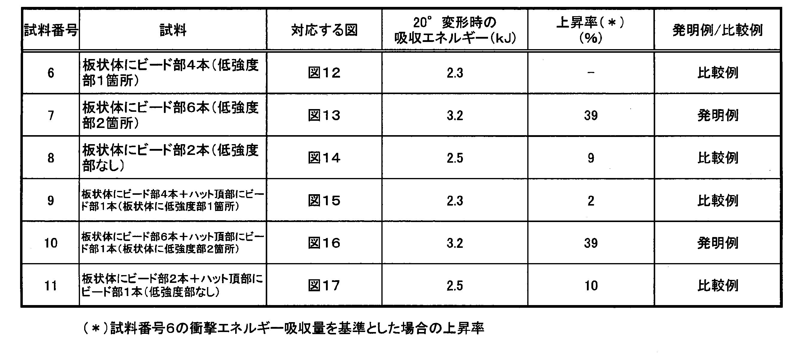
これに対し、以下では、ビード部を平行配置しない場合や、低強度部をなす間隔の長手方向位置を互いに隣り合うビード部間で相互にずらした場合について調べた。すなわち、図18~図21の各形態について数値解析を実施して対比した。
・衝撃吸収部材401の全長:700mm
・各部の幅:壁部401dは140mm、壁部401aは80mm、フランジ部402cは20mm
・成形体402の高さH:50mm
・各ビード部404の寸法と配置:両方とも、幅10mmで高さ5mmである。板状部材403の幅方向中央位置において、長手方向の一端から他端にかけて長さ335mmのビード部404が2本、長手方向30mmの間隔を空けた状態で一直線上に並んでいる。そして、長手方向中央にある前記間隔が、1箇所の低強度部404bを形成している。
衝撃吸収部材411のビード部414は、幅10mmで高さ5mmである。ビード部414は、板状部材423の幅方向中央の一端から他端にかけて連続して延在しており、低強度部が形成されていない構成となっている。
衝撃吸収部材421のビード部424は3本有り、それらの全てが幅10mmで高さ5mmである。これらビード部424は、板状部材423の幅方向中央の一端から他端にかけて同一直線上に並べられており、なおかつ板状部材423の中央近傍部分において長手方向30mmの間隔が2箇所、空けられている。そして、これら2つの間隔の間に挟まれるようにして、3本のビード部424のうちで中央に位置するものが配置されている。したがって、板状部材423の長手方向中央部には、1つの高強度部424aと、この高強度部424aを間に挟むように配置された一対の低強度部424bと、を備えた変形誘導部424Aが設けられている。そしてさらに、一対の低強度部424bに隣接して板状部材423の一端及び他端に至るビード部424が2本設けられており、これらが第2高強度部を構成している。前記間隔は、補強されていない平坦(例えば、平板のまま)となっており、低強度部424bを形成している。
この衝撃吸収部材431においては、同衝撃吸収部材431の幅方向に並んでかつ互いに平行な1対のビード部434が長手方向に沿って2組、間隔を空けて形成されている。前記間隔は、補強されていない平坦(例えば、平板のまま)となっている。
ビード部434は、長さ270mmのものが2本と、長さ400mmのものが2本との合計4本有り、それらの全てが、幅10mmで高さ5mmとなっている。互いに平行をなすように隣り合う位置関係にある各ビード部434の幅方向中央位置間の間隔は90mmである。そして、長さ270mmのもの1本と、長さ400mmのもの1本とが30mmの間隔を空けて同一直線上に並んでおり、このような組み合わせが2組、互いに平行をなして隣り合うように形成されている。ただし、前記間隔については、衝撃吸収部材431の長手方向に沿った位置が相対的にずれており、このずれた部分が、高強度部434aとなっている。
したがって、板状部材433の長手方向中央部には、1つの高強度部434aと、この高強度部434aを間に挟むように配置された一対の低強度部434bと、を備えた変形誘導部434Aが設けられている。
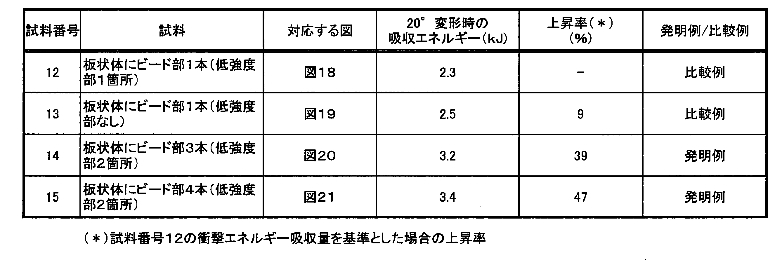
・衝撃吸収部材441の全長:700mm
・各部の幅:壁部441dは140mm、壁部441aは80mm、フランジ部442cは20mmである。
・成形体442の高さH:50mm
・ビード部444の寸法と配置:壁部441aの幅方向中央位置において、長手方向の一端から他端にかけて長さ335mmのビード部444が2本、長手方向30mmの間隔を空けた状態で同一直線上に並んでいる。これらビード部444は両方とも、幅10mmで高さ5mmである。そして、前記間隔により、1箇所の低強度部444bが形成されている。
衝撃吸収部材451のビード部454は、幅10mmで高さ5mmである。ビード部454は、壁部441aの幅方向中央の一端から他端にかけて連続して延在しており、低強度部が形成されていない構成となっている。
衝撃吸収部材461のビード部464は、3本有り、それらの全てが幅10mmで高さ5mmである。これらビード部464は、壁部461aの幅方向中央の一端から他端にかけて同一直線上に並べられており、なおかつ中央近傍部分において長手方向30mmの間隔が2箇所、空けられている。そして、これら2つの間隔の間に挟まれるようにして、3本のビード部464のうちで中央に位置するものが配置されている。したがって、壁部461aの長手方向中央部には、1つの高強度部464aと、この高強度部464aを間に挟むように配置された一対の低強度部464bと、を備えた変形誘導部464Aが設けられている。
衝撃吸収部材471の壁部471aには、その長手方向の一端から他端にかけて1本のビード部475が設けられている。また、衝撃吸収部材471の板状部材473には、4本のビード部474が設けられている。
ビード部475は、長さ700mm、幅10mm、そして高さ5mmである。
一方、ビード部474は、長さ270mmのものが2本と、長さ400mmのものが2本との合計4本有り、それらの全てが、幅10mmで高さ5mmとなっている。互いに平行をなすように隣り合う位置関係にある各ビード部474の幅方向中央位置間の間隔は90mmである。そして、長さ270mmのもの1本と、長さ400mmのもの1本とが30mmの間隔を空けて同一直線上に並んでおり、このような組み合わせが2組、互いに平行をなして隣り合うように形成されている。ただし、前記間隔については、衝撃吸収部材471の長手方向に沿った位置が相対的にずれており、このずれた部分が、高強度部474aとなっている。前記間隔は、補強されていない平坦(例えば、平板のまま)となっている。
したがって、板状部材473の長手方向中央部には、1つの高強度部474aと、この高強度部474aを間に挟むように配置された一対の低強度部474bと、を備えた変形誘導部474Aが設けられている。
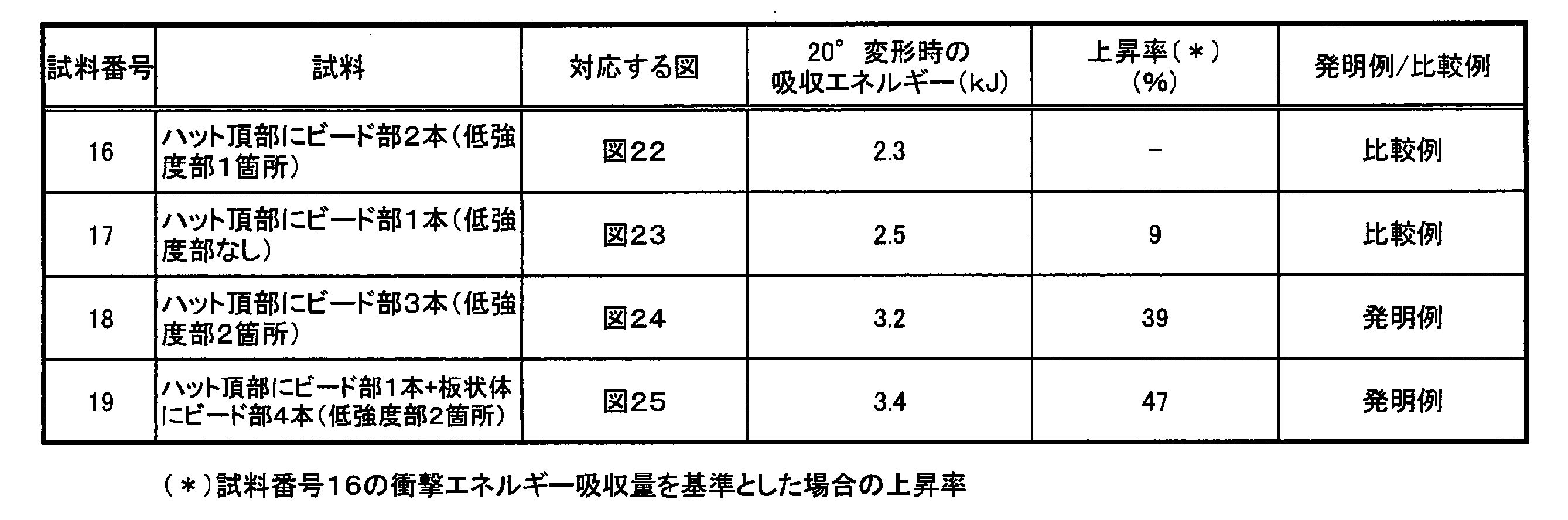
衝撃吸収部材の板状部材と同板状部材に対向するハット頂部との双方に、ビード部を設けるとともに、これらビード部のそれぞれに平坦領域(ここでは、平板ままの未加工部分)を残した場合において、各未加工部分の長手方向に沿った離間距離による衝撃エネルギー吸収性能への影響を調べた。すなわち、図26に示す離間間隔L2を変えながら数値解析を実施した。
そして、板状部材503には、同板状部材503の幅方向に並んでかつ互いに平行な1対のビード部504が長手方向に沿って3組、2つの低強度部505bを間に挟んで形成されている。各低強度部505bは、ビード部504が形成されておらず、補強されていない平坦(例えば平板のまま)となっている。
したがって、板状部材503の長手方向中央部には、長さ100mmの一対のビード部504で構成される1つの高強度部505aと、この高強度部505aを間に挟むように配置された平坦(例えば平板まま)である一対の低強度部505bと、を備えた変形誘導部505Aが設けられている。そしてさらに、一対の低強度部505bに隣接して板状部材503の一端及び他端に至るビード部504が2本、設けられており、これらが第2高強度部を構成している。
・衝撃吸収部材501の全長:1200mm
・各部の幅:壁部501dは160mm、壁部501aは90mm、フランジ部502cは20mmである。
・成形体502の高さH:50mm
・ビード部504,505の寸法と配置:全て幅10mmで高さ5mmである。高強度部505aとなる部分の長さは100mm、低強度部505bとなる未加工部の長さは20mmである。同じく低強度部として形成された変形誘導部505B,505C(未加工部)の長さも、それぞれ20mmである。

一方、表5の試料番号25,26に示すように、離間距離L2が300mmを超えると衝撃エネルギー吸収性能が下がることが確認された。すなわち、L2/Hで言うと、6.0を超えた場合に、衝撃エネルギー吸収性能が下がることが確認された。
以上の結果より、L2/Hとしては6.0以下を採用することが好ましいと判明した。
・衝撃吸収部材511の全長:1200mm
・各部の幅:壁部511dは160mm、壁部511aは90mm、フランジ部512cは20mmである。
・成形体512の高さH:50mm
・ビード部514,515の寸法と配置:全て、幅10mmで高さ5mmである。高強度部515aとなる部分の長さは100mm、低強度部515bとなる未加工部の長さは20mmである。同じく低強度部として形成された未加工部となる変形誘導部515B,515Cの長さも、それぞれ20mmである。

一方、表6の試料番号32,33に示すように、離間距離L2が300mmを超えると衝撃エネルギー吸収性能が下がることが確認された。すなわち、L2/Hで言うと、6.0を超えた場合に、衝撃エネルギー吸収性能が下がることが確認された。
以上の結果より、図27に示す衝撃吸収部材511においても、L2/Hとしては6.0以下を採用することが好ましいと判明した。したがって、衝撃エネルギー吸収性能の観点では、ビード部の本数よりも離間距離L2の大きさの方が支配的であることが表5,6の結果より確認された。
変形誘導部における高強度部の長さによる衝撃エネルギー吸収性能への影響を調べるために、図28に示す形態について、高強度部525aの長さL1を変えながら数値解析を実施した。
そして、板状部材523には、同板状部材523の幅方向に並んでかつ互いに平行な1対のビード部524が長手方向に沿って3組、2つの低強度部525bを間に挟んで形成されている。各低強度部525bは、ビード部524が形成されておらず、補強されていない平坦(例えば、平板のまま)となっている。その結果、壁部521dの長手方向中央位置には、1つの高強度部525aを間に挟んで一対の低強度部525bが形成された変形誘導部525Aが設けられている。
・衝撃吸収部材521の全長:700mm
・各部の幅:壁部521dは140mm、壁部521aは80mm、フランジ部522cは20mmである。
・成形体522の高さH:50mm
・ビード部524の寸法と配置:各ビード部524は、全て、幅10mmで高さ5mmである。互いに平行をなすように隣り合う位置にある各ビード部524間の間隔は90mmである。各ビード部524は、長さL1(mm)のものが2本と、長さ(700-L1-30×2)mmのものが4本との合計6本となっている。これらビード部524の配置は、衝撃吸収部材521の長手方向一方から他方にかけて見た場合、長さ(700-L1-30×2)mmのものが2本、間隔30mmを空けて長さL1(mm)のものが2本、そして間隔30mmを空けて長さ(700-L1-30×2)mmのものが2本、並んで配置されている。さらに、衝撃吸収部材521の幅方向一方側にある各ビード部524は全て、同一直線上に並んでいる。同様に、衝撃吸収部材521の幅方向他方側にある各ビード部524も全て、同一直線上に並んでいる。

以上説明の試料番号34~40では、板状部材523に2本のビード部524を設ける一方、壁部521aにはビード部を設けない場合について確認した。これに対し、以下では、図29に示すように、板状部材533及び壁部531aの双方に3本ずつビード部534,535を設けた衝撃吸収部材531について数値解析を実施した。その際、板状部材533の長手方向中央に設けた高強度部535aの長さL1を変えた場合の、衝撃エネルギー吸収性能への影響を調べた。
そして、板状部材533に、その幅方向中央位置において、長手方向の一端から他端に向かって3本のビード部534が一直線上に並んで形成されている。互いに隣り合う各ビード部534間には20mmの間隔が設けられており、その部分だけ補強されていない平坦(例えば、平板のまま)となっている。その結果、壁部531dの長手方向中央位置には、1つの高強度部535aを間に挟んで一対の低強度部535bが形成された変形誘導部535Aが設けられている。
また、板状部材533に対向する壁部531aにも、その幅方向中央位置において、長手方向の一端から他端に向かって3本のビード部535が一直線上に並んで形成されている。互いに隣り合う各ビード部535間には20mmの間隔が設けられており、その部分だけ補強されていない平坦(例えば、平板のまま)となっている。
・衝撃吸収部材531の全長:1200mm
・各部の幅:壁部531dは160mm、壁部531aは90mm、フランジ部532cは20mmである。
・成形体532の高さH:50mm
・ビード部534,535の寸法と配置:ビード部534,535の全てが、幅10mmで高さ5mmである。
各ビード部534の長さは、長手方向中央にある1本のビード部534がL1(mm)、その他2本のビード部534が、1/2×(1200-L1-20×2)(mm)、となっている。
一方、ビード部535においては、衝撃吸収部材531の長手方向に沿って見た場合、各変形誘導部535Bの位置が、前記低強度部535bの位置と重ならないように配置されている。そして、衝撃吸収部材531の長手方向に沿って見た場合、各変形誘導部535Bの中央位置は、前記高強度部535aの中央位置に対して250mm、相対位置がずれている。
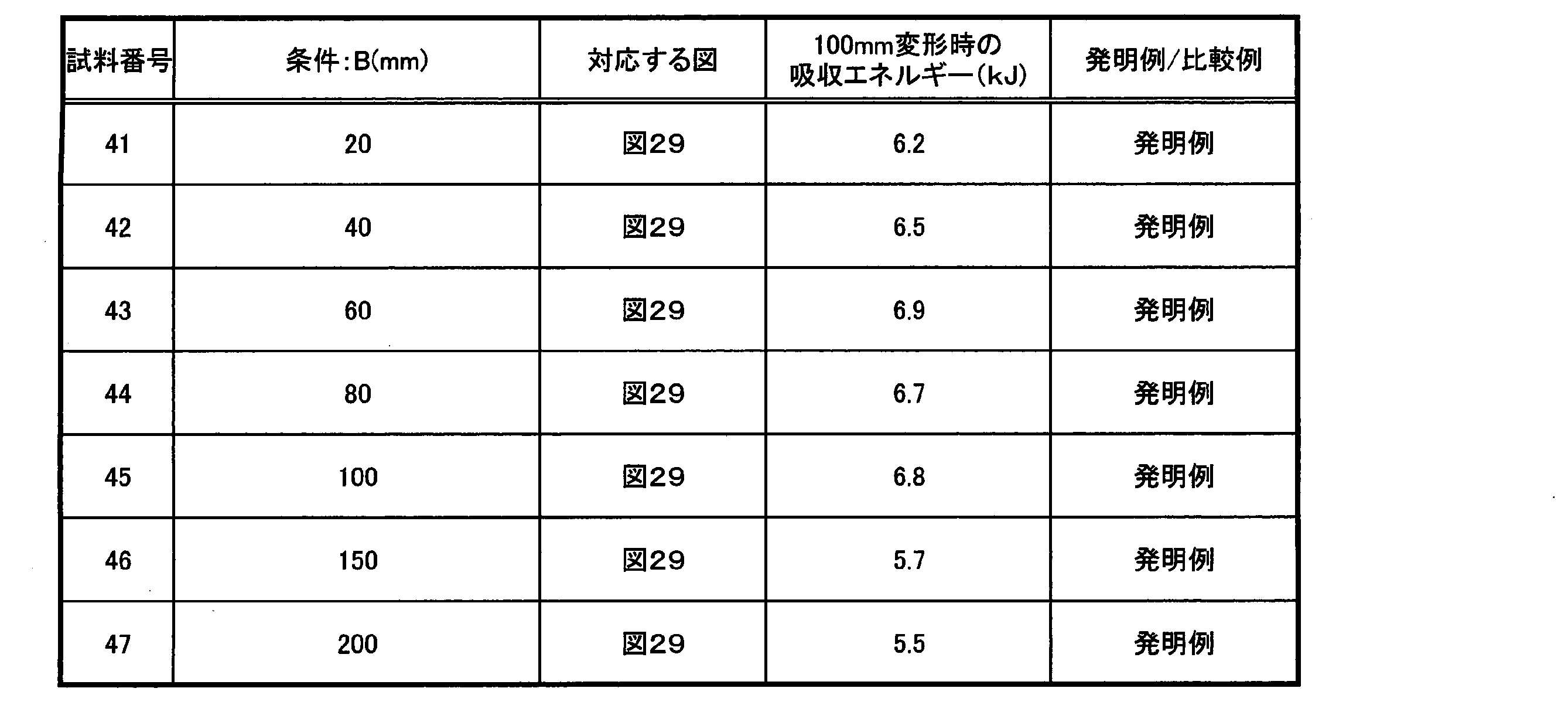
変形誘導部における低強度部の長さによる衝撃エネルギー吸収性能への影響を調べるために、図30に示す形態について、低強度部604bの長さCを変えながら数値解析を実施した。
・衝撃吸収部材601の全長:700mm
・各部の幅:壁部601dは140mm、壁部601aは80mm、フランジ部602cは20mmである。
・成形体602の高さH:50mm
・ビード部604の寸法と配置:全て幅10mmで高さ5mmである。壁部601aの幅方向中央を一端から他端にかけて3本が一直線上に並んで配置されている。そして、互いに隣り合うビード部604間には、長手方向にC(mm)の未加工部分が設けられている。そして、この一対の未加工部分の間に挟まれるようにして、各ビード部604のうちの中央位置のものが配置されている。したがって、壁部601aの長手方向中央部には、1つの高強度部604aと、この高強度部604aを間に挟むように配置された一対の低強度部604bと、を備えた変形誘導部604Aが設けられている。そしてさらに、一対の低強度部604bに隣接して壁部601aの一端及び他端に至るビード部604が2本設けられており、これらが第2高強度部を構成している。

上述の図20に示した衝撃吸収部材421の構成を用いて、ビード部の高さd(mm)及び幅w(mm)と、このビード部が設けられた壁部の板厚t(mm)とに関する好適な形状寸法を調べるために、d/t比とwとの組み合わせを変えながら数値解析を実施した。すなわち、衝撃吸収部材421の3本のビード部424の高さd(mm)を板状部材423の板厚t(mm)で除算したd/t比を1.2~4.0の範囲で変更し、さらに3本のビード部424の幅w(mm)を5mm~50mmの範囲で変更した。その他各部寸法は、衝撃吸収部材421と同じである。
上記条件の下での解析結果を、表10に示す。

さらに、上述の図20に示した衝撃吸収部材421の構成を用いて、その長手方向に沿った高強度部424aの長さL1(mm)と、変形誘導部424Aが設けられた板状部材423と同板状部材423に対向する壁部との距離をH(mm)としたときの、L1及びHに関する好適な比率を調べた。すなわち、H=50mmとして、L1を20~250mmの範囲で変えながら数値解析を実施した。
上記条件の下での解析結果を、表11に示す。
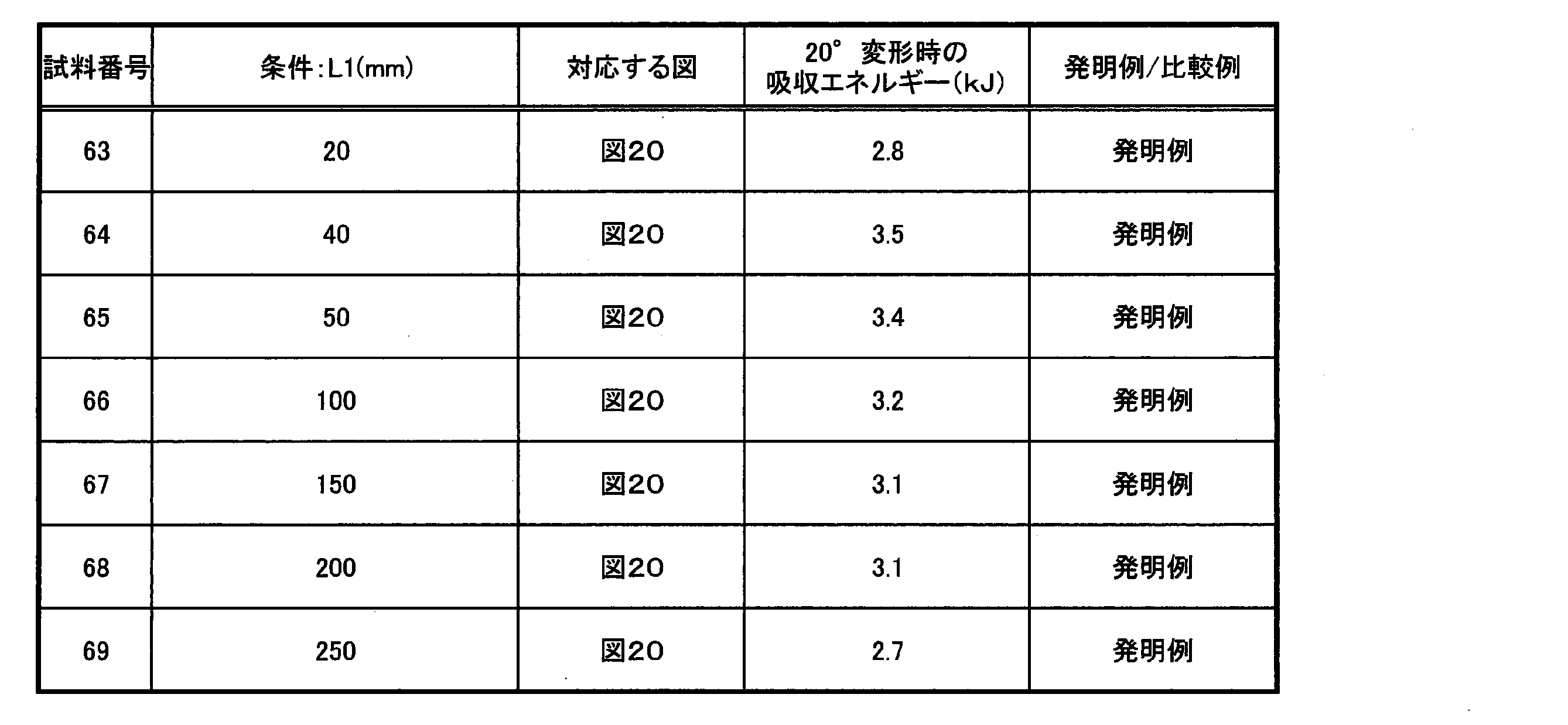
上記条件の下での解析結果を、表12に示す。
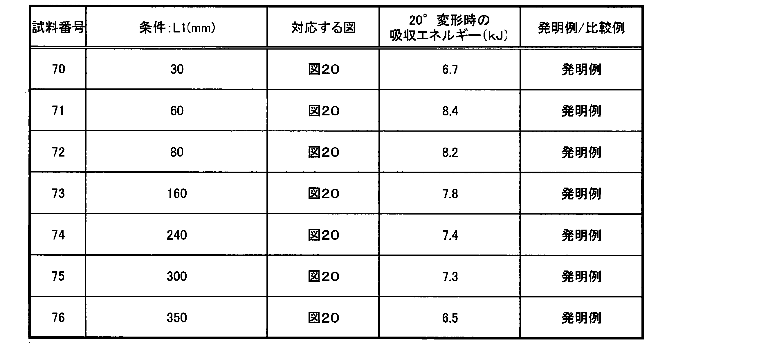
また、必要に応じ、上記各実施形態及び各実施例を適宜組み合わせた構成も採用可能である。
4,64A,64B,64C,314A,424A,434A,464A,505A,515A,525A,535A,604A 変形誘導部
4a,7,14a,24a,64a,314a,424a,434a,464a,505a,515a,525a,535a,604a 高強度部
4b,14b,24b,64b,314b,424b,434b,464b,505b,515b,525b,535b,604b 低強度部
1,11,21,61,311,341,421,431,461,501,511,521,531,601 衝撃吸収部材
3,313,423,433,503,513,523,533,603 板状部材
2c,502c,512c,522c,532c,602c フランジ部
2,512,522,532,602 成形体(ハット型部材)
5,6,15,16,17,25,26,27,28,65,314,424,434,464、504,505,514,515,524,534,535,604 ビード部
Claims (13)
- フランジ部を有してかつ長手方向に垂直な断面形状がハット頂部を有するハット型のハット型部材と、前記フランジ部に接合されてかつ前記ハット頂部に対向する板状部材と、を有する衝撃吸収部材であって、
前記ハット頂部及び前記板状部材の少なくとも一方の壁部に変形誘導部が設けられ;
前記変形誘導部が、前記壁部において相対的に座屈耐力が高い第1高強度部と、相対的に座屈耐力が低くてかつ前記長手方向に沿って見た場合に前記第1高強度部を間に挟む両側に配置された一対の低強度部と、を有し;
前記長手方向に沿って見た場合に、前記一対の低強度部のそれぞれに隣接するように前記変形誘導部の両側に配置され、前記低強度部に対して相対的に座屈強度が高い一対の第2高強度部を有する;
ことを特徴とする衝撃吸収部材。 - 前記第1高強度部の前記長手方向に沿った長さをL1(mm)とし、前記ハット頂部及び前記板状部材間の距離をH(mm)としたときに、
0.8×H≦L1≦2.0×Hである
ことを特徴とする請求項1に記載の衝撃吸収部材。 - 前記一対の低強度部それぞれの前記長手方向に沿った長さをC(mm)とし、前記ハット頂部及び前記板状部材間の距離をH(mm)としたときに、C≦0.6×Hである
ことを特徴とする請求項1又は2に記載の衝撃吸収部材。 - 前記第1高強度部は、前記壁部に、前記長手方向に沿って設けられた第1ビード部を有する
ことを特徴とする請求項1~3の何れか一項に記載の衝撃吸収部材。 - 前記第1高強度部は、前記長手方向に沿って延在するとともに相互に平行な一対の前記第1ビード部を有し;
前記一対の低強度部において、前記一対の第1ビード部の少なくとも一方の一端に隣接する領域は平坦であり、前記一対の第1ビード部の少なくとも一方の他端に隣接する領域は平坦である;
ことを特徴とする請求項4に記載の衝撃吸収部材。 - 前記一対の低強度部において、前記一対の第1ビード部の両端に隣接する領域は、平坦である
ことを特徴とする請求項5に記載の衝撃吸収部材。 - 前記一対の第2高強度部は、前記壁部に、前記長手方向に沿って設けられ、それぞれの一端が前記一対の低強度部のそれぞれに隣接し、他端が前記衝撃吸収部材の端部に至る一対の第2ビード部を有する
ことを特徴とする請求項4~6の何れか一項に記載の衝撃吸収部材。 - 前記第1ビード部が設けられた前記壁部の壁面からの前記第1ビード部の高さをd(mm)とし、前記第1ビード部の幅をw(mm)とし、前記第1ビード部が設けられた前記壁部の板厚をt(mm)とした場合に、
d/t≧2.0及びw≧10の少なくとも一方
を満たす
ことを特徴とする請求項4~7の何れか一項に記載の衝撃吸収部材。 - 前記第1高強度部が、外部から前記長手方向に沿って加重を受けた場合に前記変形誘導部が設けられた前記壁部の板厚方向外側に向かって膨出する膨出部である
ことを特徴とする請求項1~8の何れか一項に記載の衝撃吸収部材。 - 前記ハット頂部及び前記板状部材のそれぞれに、前記変形誘導部及び前記一対の第2高強度部が設けられていることを特徴とする請求項1~9の何れか一項に記載の衝撃吸収部材。
- 前記長手方向に沿って見た場合の、
前記ハット頂部及び前記板状部材の一方の前記変形誘導部に設けられた前記第1高強度部の中央位置と、
前記ハット頂部及び前記板状部材の他方の前記変形誘導部に設けられた前記一対の低強度部のうち、前記一方の変形誘導部に設けられた前記第1高強度部に近い方にある前記低強度部の中央位置と、
の前記長手方向に沿った離間距離をL2(mm)とし、
前記ハット頂部及び前記板状部材間の距離をH(mm)とした場合に、
L2≦6.0×Hである
ことを特徴とする請求項10に記載の衝撃吸収部材。 - 前記各変形誘導部のそれぞれにおいて、
前記長手方向に沿って見た場合における、前記一対の低強度部それぞれの中間位置間の離間距離をL3(mm)とし、
前記ハット頂部及び前記板状部材間の距離をH(mm)とした場合に、
0.8×H≦L3≦2.0×Hである
ことを特徴とする請求項10または11に記載の衝撃吸収部材。 - 前記各変形誘導部のそれぞれにおいて、
前記一対の低強度部それぞれの前記長手方向に沿った長さをC(mm)とし、前記ハット頂部及び前記板状部材間の距離をH(mm)とした場合に、
C≦0.6×Hである
ことを特徴とする請求項10~12の何れか一項に記載の衝撃吸収部材。
Priority Applications (7)
| Application Number | Priority Date | Filing Date | Title |
|---|---|---|---|
| PCT/JP2017/046611 WO2019130420A1 (ja) | 2017-12-26 | 2017-12-26 | 衝撃吸収部材 |
| CA3086298A CA3086298A1 (en) | 2017-12-26 | 2017-12-26 | Impact absorbing member |
| CN201780097896.1A CN111512062B (zh) | 2017-12-26 | 2017-12-26 | 冲击吸收部件 |
| JP2019561424A JP6888693B2 (ja) | 2017-12-26 | 2017-12-26 | 衝撃吸収部材 |
| KR1020207019591A KR102392028B1 (ko) | 2017-12-26 | 2017-12-26 | 충격 흡수 부재 |
| US16/957,666 US11530728B2 (en) | 2017-12-26 | 2017-12-26 | Impact absorbing member |
| MX2020006415A MX2020006415A (es) | 2017-12-26 | 2017-12-26 | Miembro de absorcion de impacto. |
Applications Claiming Priority (1)
| Application Number | Priority Date | Filing Date | Title |
|---|---|---|---|
| PCT/JP2017/046611 WO2019130420A1 (ja) | 2017-12-26 | 2017-12-26 | 衝撃吸収部材 |
Publications (1)
| Publication Number | Publication Date |
|---|---|
| WO2019130420A1 true WO2019130420A1 (ja) | 2019-07-04 |
Family
ID=67066709
Family Applications (1)
| Application Number | Title | Priority Date | Filing Date |
|---|---|---|---|
| PCT/JP2017/046611 Ceased WO2019130420A1 (ja) | 2017-12-26 | 2017-12-26 | 衝撃吸収部材 |
Country Status (7)
| Country | Link |
|---|---|
| US (1) | US11530728B2 (ja) |
| JP (1) | JP6888693B2 (ja) |
| KR (1) | KR102392028B1 (ja) |
| CN (1) | CN111512062B (ja) |
| CA (1) | CA3086298A1 (ja) |
| MX (1) | MX2020006415A (ja) |
| WO (1) | WO2019130420A1 (ja) |
Families Citing this family (2)
| Publication number | Priority date | Publication date | Assignee | Title |
|---|---|---|---|---|
| JP7568979B2 (ja) * | 2021-05-06 | 2024-10-17 | 日本製鉄株式会社 | 骨格部材 |
| DE102024100368B3 (de) * | 2024-01-08 | 2025-04-30 | Bayerische Motoren Werke Aktiengesellschaft | Querträger für ein Stoßfängersystem eines Kraftfahrzeugs, Stoßfängersystem mit einem solchen Querträger sowie Kraftfahrzeug mit einem derartigen Stoßfängersystem |
Citations (6)
| Publication number | Priority date | Publication date | Assignee | Title |
|---|---|---|---|---|
| JPH06206576A (ja) * | 1993-01-11 | 1994-07-26 | Nissan Motor Co Ltd | 車両のフロントサイドメンバ構造 |
| JP2003095132A (ja) * | 2001-09-21 | 2003-04-03 | Mazda Motor Corp | 車体のフレーム構造及び車体フレームの製造方法 |
| JP2013216185A (ja) * | 2012-04-06 | 2013-10-24 | Toyota Motor Corp | 車体構造 |
| WO2016021261A1 (ja) * | 2014-08-04 | 2016-02-11 | 本田技研工業株式会社 | 車体構造 |
| WO2016079272A1 (en) * | 2014-11-20 | 2016-05-26 | Autotech Engineering A.I.E. | Beam for producing a metal framework |
| JP2017505232A (ja) * | 2014-01-07 | 2017-02-16 | オートテック エンジニアリング エー.アイ.イー. | 屈曲角が限定された金属ビーム |
Family Cites Families (13)
| Publication number | Priority date | Publication date | Assignee | Title |
|---|---|---|---|---|
| JP2727680B2 (ja) | 1989-09-07 | 1998-03-11 | 日産自動車株式会社 | ビードの配置決定方法 |
| US5048345A (en) | 1989-08-03 | 1991-09-17 | Nissan Motor Co., Ltd. | Method of determining positions of beads |
| DE19511868A1 (de) * | 1995-03-31 | 1996-10-02 | Daimler Benz Ag | Stoßstange |
| JPH1143069A (ja) | 1997-07-29 | 1999-02-16 | Nissan Motor Co Ltd | 自動車の強度部材 |
| US6986536B1 (en) * | 2004-06-25 | 2006-01-17 | Shape Corporation | Vehicle bumper beam |
| US20060005503A1 (en) * | 2004-07-07 | 2006-01-12 | Jeffrey Bladow | Reinforced structural member and method for its manufacture |
| EP2479452A4 (en) | 2009-09-14 | 2014-10-08 | Toyota Motor Co Ltd | SHOCK ABSORBENT STRUCTURE |
| CN102959271B (zh) * | 2010-08-26 | 2015-08-05 | 新日铁住金株式会社 | 冲击吸收部件 |
| KR101242146B1 (ko) * | 2011-02-24 | 2013-03-11 | 현대로템 주식회사 | 손상방지 기능을 갖는 철도차량용 사이드 외판 변형유도 프레임 |
| JP6014430B2 (ja) * | 2012-09-12 | 2016-10-25 | 株式会社アステア | バンパー |
| JP2017035921A (ja) * | 2015-08-07 | 2017-02-16 | 豊田鉄工株式会社 | バンパリインフォースメント |
| JP6550419B2 (ja) * | 2017-05-30 | 2019-07-24 | 株式会社Subaru | バンパビーム構造 |
| US11325689B2 (en) * | 2019-05-09 | 2022-05-10 | The Boeing Company | Composite stringer and methods for forming a composite stringer |
-
2017
- 2017-12-26 CA CA3086298A patent/CA3086298A1/en not_active Abandoned
- 2017-12-26 WO PCT/JP2017/046611 patent/WO2019130420A1/ja not_active Ceased
- 2017-12-26 CN CN201780097896.1A patent/CN111512062B/zh active Active
- 2017-12-26 MX MX2020006415A patent/MX2020006415A/es unknown
- 2017-12-26 KR KR1020207019591A patent/KR102392028B1/ko active Active
- 2017-12-26 JP JP2019561424A patent/JP6888693B2/ja active Active
- 2017-12-26 US US16/957,666 patent/US11530728B2/en active Active
Patent Citations (6)
| Publication number | Priority date | Publication date | Assignee | Title |
|---|---|---|---|---|
| JPH06206576A (ja) * | 1993-01-11 | 1994-07-26 | Nissan Motor Co Ltd | 車両のフロントサイドメンバ構造 |
| JP2003095132A (ja) * | 2001-09-21 | 2003-04-03 | Mazda Motor Corp | 車体のフレーム構造及び車体フレームの製造方法 |
| JP2013216185A (ja) * | 2012-04-06 | 2013-10-24 | Toyota Motor Corp | 車体構造 |
| JP2017505232A (ja) * | 2014-01-07 | 2017-02-16 | オートテック エンジニアリング エー.アイ.イー. | 屈曲角が限定された金属ビーム |
| WO2016021261A1 (ja) * | 2014-08-04 | 2016-02-11 | 本田技研工業株式会社 | 車体構造 |
| WO2016079272A1 (en) * | 2014-11-20 | 2016-05-26 | Autotech Engineering A.I.E. | Beam for producing a metal framework |
Also Published As
| Publication number | Publication date |
|---|---|
| JPWO2019130420A1 (ja) | 2020-12-03 |
| US20200332854A1 (en) | 2020-10-22 |
| JP6888693B2 (ja) | 2021-06-16 |
| CN111512062B (zh) | 2021-12-14 |
| KR20200092396A (ko) | 2020-08-03 |
| MX2020006415A (es) | 2020-09-17 |
| CA3086298A1 (en) | 2020-06-18 |
| KR102392028B1 (ko) | 2022-04-29 |
| US11530728B2 (en) | 2022-12-20 |
| CN111512062A (zh) | 2020-08-07 |
Similar Documents
| Publication | Publication Date | Title |
|---|---|---|
| CN113490617B (zh) | 车辆用构造构件 | |
| JP7288183B2 (ja) | 車体部材 | |
| CN106795933A (zh) | 冲击吸收部件 | |
| JP7762303B2 (ja) | 車両用サイドシル | |
| US11007957B2 (en) | Bumper structural body | |
| CN111433056B (zh) | 构造部件 | |
| US11981370B2 (en) | Structural member for vehicle | |
| JP6488758B2 (ja) | 衝撃吸収部材 | |
| WO2019130420A1 (ja) | 衝撃吸収部材 | |
| EP4108546A1 (en) | Vehicle body structural member and method for designing vehicle body structural member | |
| JP2013103556A (ja) | エネルギ吸収部材およびエネルギ吸収部材の断面変形制御方法 | |
| JP7207452B2 (ja) | 自動車用構造部材、及びその製造方法 | |
| JP6125466B2 (ja) | 自動車用構造部材 | |
| JP5237927B2 (ja) | 自動車のルーフ補強部材およびその設計方法 | |
| CN114174089B (zh) | 汽车外装面板的加强构造 | |
| JP6747928B2 (ja) | 衝撃吸収部材 | |
| JP2021172117A (ja) | 自動車骨格部材および電気自動車 | |
| JP7842340B2 (ja) | 構造部材 | |
| CN116710332B (zh) | 构造构件 | |
| CN111976435B (zh) | 铝合金制车门防撞梁 | |
| JP2012081861A (ja) | 衝撃吸収部材 | |
| CN110475706B (zh) | 汽车的冲击吸收构件和纵梁 | |
| JP6156413B2 (ja) | 車両用構造部材 | |
| CN118434600A (zh) | 开口截面保险杠加强件 | |
| JP2012224202A (ja) | 圧壊特性に優れる構造部材 |
Legal Events
| Date | Code | Title | Description |
|---|---|---|---|
| 121 | Ep: the epo has been informed by wipo that ep was designated in this application |
Ref document number: 17936428 Country of ref document: EP Kind code of ref document: A1 |
|
| ENP | Entry into the national phase |
Ref document number: 2019561424 Country of ref document: JP Kind code of ref document: A |
|
| NENP | Non-entry into the national phase |
Ref country code: DE |
|
| ENP | Entry into the national phase |
Ref document number: 20207019591 Country of ref document: KR Kind code of ref document: A |
|
| 122 | Ep: pct application non-entry in european phase |
Ref document number: 17936428 Country of ref document: EP Kind code of ref document: A1 |