WO2019123774A1 - 放射線撮影システム、情報処理装置、情報処理装置の制御方法、およびプログラム - Google Patents
放射線撮影システム、情報処理装置、情報処理装置の制御方法、およびプログラム Download PDFInfo
- Publication number
- WO2019123774A1 WO2019123774A1 PCT/JP2018/037238 JP2018037238W WO2019123774A1 WO 2019123774 A1 WO2019123774 A1 WO 2019123774A1 JP 2018037238 W JP2018037238 W JP 2018037238W WO 2019123774 A1 WO2019123774 A1 WO 2019123774A1
- Authority
- WO
- WIPO (PCT)
- Prior art keywords
- radiation
- image
- energy radiation
- high energy
- low energy
- Prior art date
- Legal status (The legal status is an assumption and is not a legal conclusion. Google has not performed a legal analysis and makes no representation as to the accuracy of the status listed.)
- Ceased
Links
Images








Classifications
-
- A—HUMAN NECESSITIES
- A61—MEDICAL OR VETERINARY SCIENCE; HYGIENE
- A61B—DIAGNOSIS; SURGERY; IDENTIFICATION
- A61B6/00—Apparatus or devices for radiation diagnosis; Apparatus or devices for radiation diagnosis combined with radiation therapy equipment
Definitions
- the present invention relates to radiography technology.
- An energy subtraction method is an application of a radiography method using a radiography apparatus.
- the energy subtraction method is a method of performing subtraction processing (energy subtraction processing) on a plurality of radiation images obtained by irradiating the subject with energy of different radiation and imaging.
- the image (subtraction image) obtained by the difference processing is an image (bone image or soft tissue image) in which the bone or soft tissue of the subject is clarified.
- at least two radiation images obtained by radiography of high and low energy are required.
- more subtraction images are required to display moving images of subtraction images.
- the energy subtraction method at least two sets of radiation images are required in order to obtain one subtraction image, so the problem is that the frame rate is lowered.
- Patent Document 1 discloses a technique for displaying a moving image of a subtraction image without reducing the frame rate. Specifically, subtraction is not performed from the two images obtained in the last two frames, such as the odd frame and the even frame, and the even frame and the odd frame instead of the two images obtained in the odd frame and the even frame. It is described to obtain an image.
- the concept of effective atomic number is used to identify substances.
- the effective atomic number is a quantitative index indicating an element, a compound, or a mixture.
- the combination of radiation quality and dose (energy) suitable for the identification of the substance high energy Radiation and low energy radiation.
- high-energy radiation and low-energy radiation optimized for the target substance may be irradiated.
- it is desired to generate an image in which a plurality of substances are clearly identified such as a catheter and a blood vessel structure
- the present disclosure provides a technique for improving a frame rate for generating an image by an energy subtraction method.
- the radiography system of this invention has the following structures. That is, a first low energy radiation and a first high energy radiation for identifying the first substance, and a second low energy radiation and a second high energy for identifying the second substance Radiation generating means for continuously irradiating the radiation, the first low energy radiation, the first high energy radiation, the second low energy radiation, and the second high energy radiation; At least one of the first image for identifying the first substance and the image processing means for generating a second image for identifying the second substance.
- the frame rate for generating an energy subtraction method image is improved.
- FIG. 1 shows an overall view of a radiation imaging system 10.
- 5 shows an example of a functional configuration of the information processing apparatus 103.
- 7 shows an exemplary hardware configuration of the information processing apparatus 103.
- 6 is a configuration example of a radiation imaging apparatus 104.
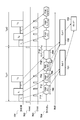
- the timing chart of the processing for generating the synthetic picture (MixXY) based on the energy subtraction method in a 1st embodiment is shown. It is a flowchart which shows operation
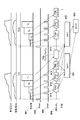
- the timing chart of the processing for generating the synthetic picture (MixXY) based on the energy subtraction method in a 2nd embodiment is shown. It is a flowchart which shows operation
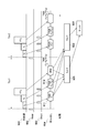
- the timing chart of the processing for generating the synthetic picture (MixXY) based on the energy subtraction method in the modification of a 2nd embodiment is shown. It is a flowchart which shows operation
- the timing chart of the processing for generating the synthetic picture (MixXY) based on the energy subtraction method in a 3rd embodiment is shown. It is a flowchart which shows operation
- the timing chart of the processing for generating the synthetic picture (MixXY) based on the energy subtraction method in the modification of a 3rd embodiment is shown. It is a flowchart which shows operation
- FIG. 1 is a view showing the concept of a substance identification procedure by the energy subtraction method.
- a radiation image high energy radiation image (H)
- a low energy radiation image (L) is acquired.
- two equations are drawn from the high energy radiation image (H) and the low energy radiation image (L), and the solution is obtained using the Newton-Raphson method and the dichotomy method to obtain the effective atomic number (Z) and the surface
- the density (D) can be determined.
- the substance can be identified by superimposing and mapping the information of the obtained effective atomic number (Z) as a hue distribution image and the information of cotton density (D) as a lightness distribution image.
- An image hereinafter, a composite image
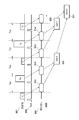
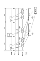
- FIG. 2 is an example of a timing chart when generating a subtraction image of each of the substance X and the substance Y by the energy subtraction method.
- a pseudo waveform (radiation 201) of radiation to be irradiated, a timing (Reset 202) for resetting charges accumulated at the time of radiography, and an image having a pixel value proportional to the amount of accumulated charges are read out
- a period (readout 203) is shown along with the time axis.
- Low-energy radiation X L and high-energy radiation X H are low-energy radiation and high-energy radiation set to identify substance X, respectively. Also, low energy radiation Y L and high energy radiation Y H are low energy radiation and high energy radiation set to identify substance Y, respectively.
- a low energy radiation image 211 is read out within the imaging cycle time Tcyc1 by the radiation X L irradiation.
- the high energy radiation image 212 is read out within the imaging cycle time Tcyc 2 by the radiation X H irradiation.
- the low energy radiation image 213 and the high energy radiation image 214 are obtained by irradiating the radiation Y L and the radiation Y H different from the radiation X L and the radiation X H. Then, a subtraction image (SubY 222) is generated by performing the same processing as when acquiring the subtraction image (SubX 221).
- the two subtraction images (SubX 221 and Sub Y 222) thus obtained are images in which the substance X and the substance Y are clarified.
- image processing for deleting the display other than the substance X is performed on the subtraction image (SubX 221).
- image processing for erasing the display other than the substance Y is performed on the subtraction image (SubY 222).
- different hues and lightnesses are given to each of the two subtraction images after the deletion processing, and then superimposed to generate a composite image (Mix XY 231).
- the composite image (Mix XY 231) By displaying the composite image (Mix XY 231) on the display means, the display of the image in which the substance X and the substance Y are clearly identified is realized.
- FIG. 3 shows an overall view of a radiation imaging system 10 according to the first embodiment.
- the radiation imaging system 10 includes a radiation generation device 101, a radiation control device 102, an information processing device 103, and a radiation imaging device (sensor) 104.
- the radiation generating apparatus 101 is configured to identify the first low energy radiation for identifying the first substance and the first high energy radiation, and the second for identifying the second substance.
- the low-energy radiation and the second high-energy radiation are continuously irradiated, and the information processing apparatus 103 is configured to identify the first substance with the first low-energy radiation and the first high-energy radiation And a first image and a second for identifying the first substance based on at least one of the second low energy radiation for identifying the second substance and the second high energy radiation. Generating a second image for identifying the substance of
- the configuration of the radiation imaging system 10 will be described in more detail.
- the radiation generating apparatus 101 generates and irradiates radiation under the control of the radiation control apparatus 102.
- the radiation control device 102 controls the dose and quality (energy) of radiation emitted from the radiation generation device 101 and the irradiation timing.
- the information processing apparatus 103 controls various timings with respect to the radiation control apparatus 102. Further, the information processing apparatus 103 acquires a radiation image generated by the radiation imaging apparatus 104, and performs image processing on the acquired radiation image.
- the radiation imaging apparatus 104 receives radiation emitted from the radiation generation apparatus 101, generates a radiation image as radiation intensity distribution information, and outputs the radiation image to the information processing apparatus 103.
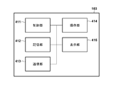
- FIG. 4A shows a functional configuration of the information processing apparatus 103
- FIG. 4B shows a hardware configuration of the information processing apparatus 103.
- the information processing apparatus 103 includes an image acquisition unit 401, an image processing unit 402, a display control unit 403, a timing setting unit 404, a radiation setting unit 405, and a substance setting unit 406 as functional components.
- the image acquisition unit 401 acquires a radiation image generated by the radiation imaging apparatus 104.
- the image processing unit 402 performs various image processing to be described later on the radiation image acquired by the image acquisition unit 401.
- the display control unit 403 performs various displays on the display unit 415 (FIG. 4B).
- the timing setting unit 404 sets various timings on the radiation imaging apparatus 104.
- the radiation setting unit 405 sets, for example, the energy level of the radiation emitted by the radiation generation apparatus 101 to the radiation generation apparatus 101.
- the substance setting unit 406 sets a substance to be identified. Note that various settings of the timing setting unit 404, the radiation setting unit 405, and the substance setting unit 406 can be made according to an operation on the operation unit 414 (FIG. 4B) by the user.
- the information processing apparatus 103 includes a control unit 411, a storage unit 412, a communication unit 413, an operation unit 414, and a display unit 415 as a hardware configuration.
- the control unit 411 is, for example, a CPU (Central Processing Unit), and controls the operation of each component.
- the storage unit 412 is configured of a read only memory (ROM) or a random access memory (RAM).
- the storage unit 412 can store control instructions or programs.
- the storage unit 412 can also be used for temporary storage of a work memory or data when executing a program.
- the communication unit 413 performs control for communicating with an external device.
- the operation unit 414 receives an operation by the user.
- the display unit 415 performs various displays.
- the display unit 415 is, for example, a display panel that displays image data.
- the display panel may be configured by a method such as LCD (Liquid Crystal Display), plasma, or organic EL.
- a GUI Graphic User Interface
- the operation unit 414 and the display unit 415 may be formed by the operation unit 414 and the display unit 415.
- FIG. 5 shows a configuration example of the radiation imaging apparatus 104.
- the radiation imaging apparatus 104 functions as a radiation image generation unit that detects the emitted radiation and generates a radiation image, and includes a radiation signal acquisition unit 501, a reset unit 502, a sample hold unit 503, and a readout unit 504. .
- the radiation signal acquisition unit 501 converts the radiation emitted from the radiation generation device 101 into charges proportional to the amount and stores the charges.
- the reset unit 502 resets the charge accumulated in the radiation signal acquisition unit 501.
- the sample hold unit 503 acquires and stores the charge of the radiation signal acquisition unit 501.
- the information processing apparatus 103 controls the timing at which the reset unit 502 resets the charge and the timing at which the sample and hold unit 503 acquires the charge. These timings may be configured to be directly controlled by the radiation generating apparatus 101 or the user.
- the reading unit 504 reads the charges accumulated in the sample and hold unit 503, and acquires the read radiation intensity distribution information as a radiation image.
- the radiation imaging apparatus 104 can store a plurality of radiation images acquired by the reading unit 504.
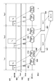
- FIG. 6A shows a timing chart of a process for generating a composite image (MixXY) based on the energy subtraction method in the first embodiment.
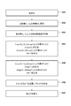
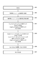
- FIG. 6B is a flowchart showing an operation of the radiation imaging system 10 corresponding to the timing chart shown in FIG. 6A.
- a pseudo waveform (radiation 601) of radiation irradiated by the radiation generation apparatus 101, an operation timing (Reset 602) of the reset unit 502, an acquisition timing (SHold 603) of the sample and hold unit 503, and an image by the reading unit 504
- the readout period (readout 604) is shown along with the time axis.
- the radiation generation apparatus 101 performs irradiation continuously by changing the dose and radiation quality (energy) of radiation in one imaging cycle time. Specifically, the radiation generating apparatus 101 generates a first low energy radiation (radiation X L ) and a first high energy radiation for identifying a first substance (substance X) at a predetermined imaging cycle time. Second low energy radiation (radiation) for continuously irradiating radiation (radiation X H ) and identifying a second substance (substance Y) in the next imaging cycle time of the predetermined imaging cycle time Irradiate Y L ) and second high energy radiation (radiation Y H ) sequentially.
- the radiation imaging apparatus 104 generates a first radiation image and a second radiation image based on the first low energy radiation and the first high energy radiation in the predetermined imaging cycle time.
- a third radiation image and a fourth radiation image are generated based on the second low energy radiation and the second high energy radiation.
- the information processing apparatus 103 generates a first image (SubX) for identifying the first substance based on the first radiation image and the second radiation image, and the third information
- a second image (SubY) for identifying the second substance is generated based on the radiation image and the fourth radiation image.
- the information processing apparatus 103 generates a first subtraction image (SubX) based on the first radiation image and the second radiation image, and based on the third radiation image and the fourth radiation image.
- a second subtraction image (SubY) is generated.
- the first image and the second image may be generated by the radiation imaging apparatus 104.
- the reset unit 502 of the radiation imaging apparatus 104 resets and initializes the charges accumulated by the radiation signal acquisition unit 501 (S61).
- the radiation generating apparatus 101 continuously irradiates the radiation X L and the radiation X H (S62).
- the radiation signal acquisition unit 501 of the radiation imaging apparatus 104 converts the irradiated radiation into a charge proportional to the amount and stores it.
- the sample and hold unit 503 of the radiation imaging apparatus 104 acquires and accumulates the charges due to the radiation X L and X H accumulated by the radiation signal acquisition unit 501 at different timings.
- the reading unit 504 reads the charges accumulated in the sample and hold unit 503, and acquires and stores the read radiation intensity distribution information as a radiation image (S63).
- the radiation images stored here are a radiation image 611 (Image (X L )) and a radiation image 612 (Image (X L + X H )).
- a radiation image 611 (Image (X L )) corresponds to the charge accumulated in the period from the reset timing by the reset unit 502 to the completion of irradiation of the radiation X L (the timing of the first SHold 603 in the imaging cycle time Tcyc1). It is an image.
- a radiation image 612 (Image (X L + X H )) is an image corresponding to the charge accumulated in the period from the reset timing by the reset unit 502 to the completion of irradiation of the radiation X H (the timing of the second SHold 603).
- the information processing apparatus 103 acquires a radiation image 611 (Image (X L )) and a radiation image 612 (Image (X L + X H )) stored in the radiation imaging device 104, and performs energy subtraction processing, Generate a subtraction image. Specifically, the image processing unit 402 of the information processing apparatus 103 obtains the difference between the radiation image (Image (X L )) and the radiation image 612 (Image (X L + X H )) by taking the difference. Generate (X H )). Subsequently, the image processing unit 402 generates a subtraction image 621 (SubX) by taking the difference between the radiation image 611 (Image (X L )) and the radiation image (Image (X H )) (S64). The image processing unit 402 may perform filter processing as necessary to generate a subtraction image.
- the image processing unit 402 of the information processing apparatus 103 further combines the subtraction image 621 (SubX) and the subtraction image 622 (SubY) to generate a combined image (MixXY) (S66). Specifically, the image processing unit 402 changes the hue or the like of each of the subtraction image 621 (SubX) and the subtraction image 622 (SubY) after the image processing for erasing the display other than the substance X and the substance Y. The lightness is given and then superimposed to generate a composite image 631 (MixXY). The image processing unit 402 may combine the subtraction image 621 (SubX) and the subtraction image 622 (SubY) so as to be displayed in parallel. The display control unit 403 displays the composite image 631 (MixXY) generated by the image processing unit 402 on the display unit 415 (S67).
- the display control unit 403 displays the composite image (MixXY) on the display unit 415 while being updated.
- each of the readout times 605 and 606 is sufficiently short with respect to the period of the imaging cycle times Tcyc1 and Tcyc2, generation and display of subtraction images and composite images for the substance X and the substance Y at a higher frame rate. It becomes possible. That is, conventionally, one composite image (MixXY) is generated in a period of four imaging cycle times as shown in FIG. 2, while in the present embodiment, a period of two imaging cycle times is generated. One composite image 631 (Mix XY) can be generated. The user can easily carry out a procedure such as catheter insertion that requires display at a high frame rate while clearly distinguishing the desired substance from the composite image 631 (MixXY) displayed on the display unit 415. It becomes possible.
- Second Embodiment when two types of substances are identified, imaging using four types of radiation X L , X H , Y L , and Y H having different doses and qualities (energy) is efficiently performed. A method different from the first embodiment will be described.
- the configuration of the radiation imaging system 10 is the same as that of the first embodiment.
- FIG. 7A shows a timing chart of a process for generating a composite image (MixXY) based on the energy subtraction method in the second embodiment.
- FIG. 7B is a flowchart showing an operation of the radiation imaging system 10 corresponding to the timing chart shown in FIG. 7A.
- the read out period (read out 704) is shown along with the time axis.
- the radiation generating apparatus 101 performs irradiation continuously by changing the dose and radiation quality (energy) of radiation in multiple stages during one irradiation of radiation.
- the radiation generating apparatus 101 is configured to: first low energy radiation (radiation X L ) and first high energy radiation for identifying a first substance (substance X) at a predetermined imaging cycle time
- the radiation (radiation X H ) and the second low energy radiation (radiation Y L ) and the second high energy radiation (radiation Y H ) for identifying the second substance (substance Y) are continuous. Irradiate.
- the radiation imaging apparatus 104 performs the first low energy radiation, the first high energy radiation, the second low energy radiation, and the second high energy in the predetermined imaging cycle time.
- the first radiation image, the second radiation image, the third radiation image, and the fourth radiation image are generated based on at least one of the radiations of
- the information processing apparatus 103 determines the first substance based on at least one of the first radiation image, the second radiation image, the third radiation image, and the fourth radiation image.
- a first image (SubX) to identify and a second image (SubY) to identify the second substance are generated.
- the information processing apparatus 103 generates a first subtraction image (SubX) based on the first radiation image and the second radiation image, and based on the third radiation image and the fourth radiation image.
- a second subtraction image (SubY) is generated.
- the first image and the second image may be generated by the radiation imaging apparatus 104.
- the reset unit 502 of the radiation imaging apparatus 104 resets and initializes the charges accumulated by the radiation signal acquisition unit 501 (S71).
- the radiation generating apparatus 101 continuously irradiates radiation X L , X H , Y L and Y H (S72).
- the radiation signal acquisition unit 501 of the radiation imaging apparatus 104 converts the irradiated radiation into a charge proportional to the amount and stores it.
- the sample-and-hold unit 503 of the radiation imaging apparatus 104 acquires and accumulates the charges due to the radiation X L , X H , Y L , and Y H accumulated by the radiation signal acquisition unit 501 at different timings.
- the reading unit 504 reads the charge accumulated in the sample and hold unit 503, and acquires and stores the read radiation intensity distribution information as a radiation image (S73).
- the radiation images stored here are a radiation image 711 (Image (X L )), a radiation image 712 (Image (X L + X H )), a radiation image 713 (Image (X L + X H + Y L )), and a radiation It is an image 714 (Image (X L + X H + Y L + Y H )).
- a radiation image 711 (Image (X L )) corresponds to the charge accumulated in the period from the reset timing by the reset unit 502 to the completion of irradiation of the radiation X L (the timing of the first SHold 703 in the imaging cycle time Tcyc1). It is an image.
- a radiation image 712 (Image (X L + X H ) is an image corresponding to the charge accumulated in a period from the reset timing by the reset unit 502 to the completion of irradiation of the radiation X H (the timing of the second SHold 703).
- a radiation image 713 (Image (X L + X H + Y L )) is an image corresponding to the charge accumulated in the period from the reset timing by the reset unit 502 to the completion of irradiation of the radiation Y L (the timing of the third SHold 703). It is.
- the radiation image 714 (Image (X L + X H + Y L + Y H )) corresponds to the charge accumulated in the period from the reset timing by the reset unit 502 to the completion of the irradiation of the radiation Y H (the timing of the fourth SHold 703). Image.
- the information processing apparatus 103 acquires the radiation images 711 to 714 stored in the radiation imaging apparatus 104, performs energy subtraction processing, and generates a subtraction image. Specifically, the image processing unit 402 of the information processing apparatus 103 obtains the difference between the radiation image (Image (X L )) and the radiation image 712 (Image (X L + X H )) by taking the difference. Generate Image (X H )). Subsequently, the image processing unit 402 generates a subtraction image 721 (SubX) by taking the difference between the radiation image 711 (Image (X L )) and the radiation image (Image (X H )) (S74).
- the image processing unit 402 takes a difference between the radiation image 713 (Image (X L + X H + Y L )) and the radiation image 712 (Image (X L + X H )) to obtain a radiation image (Image (Y L )). Generate).
- the image processing unit 402 also obtains a radiation image (Image (Image (X L + X H + Y L ))) and a radiation image 714 (Image (X L + X H + Y L + Y H )) by taking the difference. Y H )) is generated.
- the image processing unit 402 generates a subtraction image 722 (SubY) by taking the difference between the radiation image (Image (Y L )) and the radiation image (Image (Y H )) (S75).
- the image processing unit 402 may perform filter processing as necessary to generate the subtraction image 721 (SubX) and the subtraction image 722 (SubY).
- the information processing apparatus 103 can also start the energy subtraction process before acquiring all of the radiation images 711 to 714 from the radiation imaging apparatus 104.
- the image processing unit 402 of the information processing apparatus 103 acquires a radiation image 711 (Image (X L )) and a radiation image 712 (Image (X L + X H )) in parallel with performing energy subtraction processing.
- a radiation image 713 (Image (X L + X H + Y L )) and a radiation image 714 (Image (X L + X H + Y L + Y H )) may be acquired.
- the image processing unit 402 of the information processing device 103 combines the subtraction image 721 (SubX) and the subtraction image 722 (SubY) to generate a combined image (MixXY) (S76). Specifically, the image processing unit 402 changes the hue or the like of each of the subtraction image 721 (SubX) and the subtraction image 722 (SubY) after the image processing for erasing the display other than the substance X and the substance Y. The lightness is given and then superimposed to generate a composite image 731 (MixXY) (S76). The image processing unit 402 may combine the subtraction image 621 (SubX) and the subtraction image 622 (SubY) so as to be displayed in parallel. The display control unit 403 displays the composite image 731 (MixXY) generated by the image processing unit 402 on the display unit 415 (S77).
- the radiation generating apparatus 101 in order to distinguish the substance X and the substance Y, the radiation generating apparatus 101 generates four types of radiation X L , X H , Y L and Y H having different doses and qualities (energy).
- An example of continuous irradiation in this order has been described.
- the control load in the radiation control apparatus 102 becomes heavy. Therefore, as a modified example of the second embodiment, an example in which the radiation generating apparatus 101 irradiates radiation having an energy distribution in which vertical motion is suppressed will be described using FIGS. 8A and 8B.
- FIG. 8A shows a timing chart of processing for generating a composite image (MixXY) based on the energy subtraction method in the present modification.
- FIG. 8B is a flowchart showing an operation of the radiation imaging system 10 corresponding to the timing chart shown in FIG. 8A.
- FIG. 8A a pseudo waveform (radiation 801) of radiation irradiated by the radiation generation apparatus 101, operation timing (Reset 802) of the reset unit 502, acquisition timing (SHold 803) of the sample and hold unit 503, and an image by the reading unit 504
- the read out period (read out 804) is shown along with the time axis.
- the first low energy radiation and the first high energy radiation for identifying the first substance and the second low energy radiation and the second for identifying the second substance.
- High-energy radiation such that the energy levels are arranged in ascending order. That is, the radiation generating apparatus 101 continuously irradiates the radiation Y L , X L , X H , and Y H in this order so that the value [kV] of the tube voltage of the radiation becomes a value near the right shoulder.
- the radiation image read by the reading unit 504 is different from that of the second embodiment described above.
- the read unit 504 After initialization by the reset unit 502 (S81), the read unit 504, the radiation image 811 (Image (Y L)) , the radiation image 812 (Image (Y L + X L)), the radiation image 813 (Image (Y L The image data is read out and stored in the order of + X L + X H )) and radiation image 814 (Image (Y L + X L + X H + Y H )) (S82, S83).
- the information processing apparatus 103 acquires the radiation images 811 to 814 stored in the radiation imaging apparatus 104, performs energy subtraction processing, and generates a subtraction image. Specifically, the image processing unit 402 of the information processing apparatus 103, by taking the difference between the radiation image 812 (Image (Y L + X L)) and the radiation image 811 (Image (Y L)) , a radiation image ( Generate Image (X L )).
- the image processing unit 402 by taking the difference of the radiation image 813 (Image (Y L + X L + X H)) with the radiation image 812 (Image (Y L + X L)), image (Image (X H)) Generate Subsequently, the image processing unit 402 generates a subtraction image 821 (SubX) by taking the difference between the radiation image (Image (X L )) and the radiation image (Image (X H )) (S84). Next, the image processing unit 402, by taking the difference between the radiation image 814 (Image (Y L + X L + X H + Y H)) with the radiation image 813 (Image (Y L + X L + X H)), a radiation image Generate (Image (Y H )).
- the image processing unit 402 generates a subtraction image 822 (SubY) by taking the difference between the radiation image (Image (Y H )) and the radiation image 811 (Image (Y L )) (S85).
- the subsequent processes (S86 and S87) are the same as the processes of S76 and S77 of FIG. 7B described in the second embodiment.
- the radiation generating apparatus 101 suppresses the vertical movement and continuously changes the dose and quality (energy) to irradiate radiation.
- the control load on the radiation control apparatus 102 can be reduced.
- the radiation imaging system 10 is the same as that of the first embodiment.
- a first low energy radiation (radiation X L ) for identifying a first substance (substance X) and a second low energy radiation for identifying a second substance (substance Y) When the energy difference of the radiation (radiation Y L ) is within the predetermined threshold, the radiation generating apparatus 101 emits a common low energy radiation (radiation XY L ) in which the two radiations are made common.
- the radiation generating apparatus 101 emits a common high energy radiation (radiation XY H ) in which the two radiations are made common.
- FIG. 9A shows a timing chart of a process for generating a composite image (MixXY) based on the energy subtraction method in the third embodiment.
- FIG. 9B is a flowchart showing an operation of the radiation imaging system 10 corresponding to the timing chart shown in FIG. 9A.
- FIG. 9A a pseudo waveform (radiation 901) of radiation irradiated by the radiation generation apparatus 101, an operation timing (Reset 902) of the reset unit 502, an acquisition timing (SHold 903) of the sample and hold unit 503, and an image by the reading unit 504
- the read out period (read out 904) is shown along with the time axis.
- the energy increases in the order of the radiation Y L , X L , X H , and Y L , and the radiation generating apparatus 101 is in the middle of one radiation irradiation.
- the energy of radiation is changed stepwise.
- the two radiations are regarded as a common high energy radiation (radiation An example of common use as XY H ) will be described.
- commonization includes adjusting to one of the energy of two radiation of the object to be common, and using averaged energy.
- the determination as to whether to make common or not may be performed based on the user's operation as described later in the fourth embodiment, but is not limited thereto.
- the reset unit 502 of the radiation imaging apparatus 104 resets and initializes the charges accumulated by the radiation signal acquisition unit 501 (S91).
- the radiation generating apparatus 101 continuously irradiates the radiation Y L , X L and XY H (S92).
- the radiation signal acquisition unit 501 of the radiation imaging apparatus 104 converts the irradiated radiation into a charge proportional to the amount and stores it.
- the sample-and-hold unit 503 of the radiation imaging apparatus 104 acquires and accumulates the charges due to the radiation X L , Y L , and XY H accumulated by the radiation signal acquisition unit 501 at different timings.
- the reading unit 504 reads the charges accumulated in the sample and hold unit 503, and acquires and stores the read radiation intensity distribution information as a radiation image (S93). Radiation image stored here, the radiation image 911 (Image (Y L)) , the radiation image 912 (Image (Y L + X L)), is a radiation image 913 (Image (Y L + X L + XY H)).
- a radiation image 911 corresponds to the charge accumulated in the period from the reset timing by the reset unit 502 to the completion of irradiation of the radiation Y L (the timing of the first SHold 903 in the imaging cycle time Tcyc). It is an image.
- a radiation image 912 (Image (Y L + X L )) is an image corresponding to the charge accumulated in a period from the reset timing by the reset unit 502 to the completion of irradiation of the radiation X L (the second timing of SHold 903).
- Radiation image 913 (Image (Y L + X L + XY H)) is an image corresponding to the charge accumulated in the period from the reset timing by the reset unit 502 to the irradiation completion of radiation XY L (3-th timing SHold903) It is.
- the information processing apparatus 103 acquires the radiation images 911 to 913 stored in the radiation imaging apparatus 104, performs energy subtraction processing, and generates a subtraction image. Specifically, the image processing unit 402 of the information processing apparatus 103, the radiation image 911 (Image (Y L)) and the radiation image 912 (Image (Y L + X L)) and a radiation image by taking the difference (Image Generate (X L )). Further, the image processing unit 402 obtains a difference between the radiation image 912 (Image (Y L + X L )) and the radiation image 913 (Image (Y L + X L + XY H )) to obtain a radiation image (Image (XY H). ))).
- the image processing unit 402 generates a subtraction image 922 (SubX) by taking the difference between the radiation image (Image (X L )) and the radiation image (Image (XY H )) (S94). .
- the image (Image (XY H ) the previously acquired image (Image (XY H )) may be used.
- the image processing unit 402 generates a subtraction image 922 (SubY) by taking the difference between the radiation image (Image (XY H )) and the radiation image 911 (Image (Y L )) (S95).
- the subsequent processes (S96 and S97) are similar to the processes of S66 and S67 of FIG. 6B described in the first embodiment.
- the radiation imaging apparatus 104 can sample-hold and hold in addition to the effects of the embodiments described above. It is possible to reduce the number of readings. If the difference between the levels of the low energy radiations set to identify the substance X and the substance Y is within a predetermined threshold, the two radiations are used as the common low energy radiation (radiation XY The same process as that of the present embodiment can be applied to the case where L 1 ) is shared.
- the radiation generating apparatus 101 irradiates radiation of three types of energy continuously changed at one imaging cycle time Tcyc.
- the radiation generation apparatus 101 continuously changes the radiation of the three types of energy in one imaging cycle time Tcyc1 because of the performance limitation. Irradiating can be difficult. Therefore, as a modification of the third embodiment, when the difference between the low energy radiation X L and Y L and the high energy radiation X H is greater than or equal to a predetermined threshold, the low energy radiation X L and Y L an example of separating the irradiation timing of the high-energy radiation XY H, is described with reference to FIGS. 10A and 10B.
- FIG. 10A shows a timing chart of a process for generating a composite image (MixXY) based on the energy subtraction method in the present modification.
- FIG. 10B is a flowchart showing the operation of the radiation imaging system 10 corresponding to the timing chart shown in FIG. 10A.
- Figure 9 differs from that described in the second embodiment, the radiation generating apparatus 101, the radiation XY H of high energy, is to irradiation with low-energy radiation X L, imaging cycle time different from Y L. That is, in FIG. 10A, the radiation generating apparatus 101 irradiates low energy radiation X L and Y L at the imaging cycle time Tcyc 1 and applies high energy radiation XY H at the subsequent imaging cycle time Tcyc 2 (S101).
- the reading unit 504 of the radiation imaging apparatus 104 has a radiation image 1011 (Image (Y L )), a radiation image 1012 (Image (Y L + X L )), and a radiation image 1013 (Image (XY H )). Read and save in order.
- the information processing apparatus 103 acquires the radiation images 1001 to 1003 stored in the radiation imaging apparatus 104, performs energy subtraction processing, and generates a subtraction image. Specifically, the image processing unit 402 of the information processing apparatus 103, by taking the difference between the radiographic image 1012 (Image (Y L + X L)) and the radiation image 1011 (Image (Y L)) , a radiation image ( Generate Image (X L )). Subsequently, the image processing unit 402 generates a subtraction image 1021 (SubX) by taking the difference between the radiation image (Image (X L )) and the radiation image 1013 (Image (XY H )) (S102).
- a subtraction image 1021 SubX
- the image processing unit 402 by taking the difference between the radiographic image 1011 (Image (Y L)) and the radiation image 1013 (Image (XY H)) , and generates the subtraction image 1022 (SubY) (S103) .
- the subsequent processes (S104 and 105) are the same as the processes of S66 and S67 of FIG. 6B described in the first embodiment.
- the frame rate is lower than the method according to the second embodiment, in addition to the effects described in the third embodiment, the load on the radiation generation of the radiation generation apparatus is suppressed. Is possible.
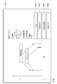
- FIGS. 11A to 11E are screen display examples of the display unit 415 of the information processing apparatus 103 when the user selects two types of identification target substances.
- a graphic user interface is formed by the display unit 415 and the operation unit 414, and the user operation is to perform the operation described below on the GUI.
- FIG. 11A shows an initial screen 1101 displayed on the display unit 415 for an operation of selecting two types of substances to be identified.
- an identification item list 1102 Puncture, stent, fine blood vessel, bone, etc.
- a synthetic button 1103, a commonization completion button 1104, a commonization cancellation button 1105, a setting completion button 1106 is displayed.
- the identification item list 1102 may include metal, resin, and the like in addition to the components of the living body. Further, the combination button 1103, the commonization completion button 1104, the commonization cancellation button 1105, and the setting completion button 1106 will be described later.
- the initial screen 1101 further displays a radiation energy distribution table 1107 set to identify each substance included in the identification item list 1102 according to the user's operation.
- the ordinate represents the irradiation time ([t])
- the abscissa represents the distribution chart showing the quality (tube voltage [kV]), but this is an example, and other displays It may be a distribution table of radiation energy in the form.
- the user selects a substance to be identified from the identification item list 1102 via the operation unit 414.
- the user operates the operation unit 414 to check the check box shown beside each item.
- An example screen after selecting “catheter” as a substance to be identified is shown in FIG. 11B.
- the “catheter” check box in the identification item list 1102 is checked on the screen 1111 of FIG. 11B.
- the distribution table 1112 of radiation energy includes radiation energy at the time of low energy imaging used to identify the “catheter” and radiation energy at the time of high energy imaging Is displayed as a bar.
- the user selects the substance "microvessel” to be identified simultaneously with the "catheter” from the identification item list 1102.
- An example of the screen after selecting “fine blood vessel” as a substance to be identified is shown in FIG. 11C.
- the “catheter” and the “fine blood vessel” check boxes in the identification item list 1102 are checked on the screen 1121 of FIG. 11C.
- the radiation energy distribution table 1122 includes radiation energy at the time of low energy imaging used for identifying “fine blood vessels” and radiation at the time of high energy imaging Energy is also displayed in a bar.
- the user selects the setting completion button 1106.
- the substance setting unit 406 sets the first substance and the second substance to be identified, and the information processing apparatus 103 performs various settings in accordance with the setting of the substance by the substance setting unit 406.
- the radiation setting unit 405 causes the radiation generation apparatus 101 to execute the A first low energy radiation (radiation X L ) and a first high energy radiation (radiation X H ) are sequentially irradiated to identify the substance 1 (substance X), and the predetermined imaging cycle time The second low energy radiation (radiation Y L ) and the second high energy radiation (radiation Y H ) for identifying the second substance (substance Y) continuously in the next imaging cycle time of Set to irradiate.
- the timing setting unit 404 causes the radiation imaging apparatus 104 to generate a first radiation image and a second radiation image based on the first low energy radiation and the first high energy radiation as the predetermined radiation image.
- a timing for generating a third radiation image and a fourth radiation image based on the two low energy radiations and the second high energy radiation at the next imaging cycle time is generated at the imaging cycle time.
- the image processing unit 402 performs a first image for identifying the first substance based on the first radiation image generated by the radiation imaging apparatus 104 and the second radiation image ( It operates to generate SubX) and generate a second image (SubY) for identifying the second substance based on the third radiation image and the fourth radiation image.
- the radiation setting unit 405 causes the radiation generation device 101 to generate the first substance (substance X) a first low energy radiation (radiation X L ) and a first high energy radiation (radiation X H ), and a second low energy radiation for identifying the second substance
- the radiation (Y L ) and the second high energy radiation (Y H ) are set to be irradiated continuously.
- the timing setting unit 404 causes the radiation imaging apparatus 104 to receive the first low energy radiation, the first high energy radiation, the second low energy radiation, and the second high energy.
- the timing for generating the first radiation image, the second radiation image, the third radiation image, and the fourth radiation image at the predetermined imaging cycle time is set based on at least one of the radiations.
- the image processing unit 402 causes at least one of the first radiation image, the second radiation image, the third radiation image, and the fourth radiation image generated by the radiation imaging apparatus 104. , And generates a first image (SubX) for identifying the first substance and a second image (SubY) for identifying the second substance.
- the radiation setting unit 405 instructs the radiation generation device 101 to perform the first low energy radiation and the radiation.
- the first high energy radiation, the second low energy radiation, and the second high energy radiation are set to be irradiated in an ascending order of energy levels.
- the radiation energy distribution table 1122 in FIG. 11C when the radiation energy at the time of low energy imaging of each of the “catheter” and the “fine blood vessel” is similar, these radiation energy Can also be used in common (third embodiment).
- the user decides to use a plurality of radiation energy in common, the user selects the combining button 1103.
- a circle for selecting radiation energy to be shared is displayed in the radiation energy distribution table 1142 in the screen 1141 of FIG. 11D.
- the user can designate the radiation energy to be shared by arranging the circle so as to surround the radiation energy to be shared.
- the user selects the commonization completion button 1104, and in response to the selection, the radiation energy distribution table 1152 in the screen 1151 of FIG. It will be displayed as On the other hand, in the case of releasing the common use radiation energy, the user selects the common use cancellation button 1105. Conversely, if it is desired to further commonize, the user selects the composite button 1103 again.
- the user selects the setting completion button 1106. In response to this, the substance setting unit 406 sets commonality to the first substance to be identified and the second substance, and according to the substance and the commonization setting by the substance setting unit 406, the information processing apparatus 103 performs various operations. Make settings.
- the radiation setting unit 405 instructs the radiation generation device 101 to It is set to emit a common low energy radiation (radiation XY L ) that is common to the first low energy radiation and the second low energy radiation.
- an operation indicating that the difference between the energy of the first high energy radiation (radiation X H ) and the energy of the second high energy radiation (radiation Y H ) is within a predetermined first threshold is performed If the radiation setting unit 405 performs the operation (1) for the user), the radiation setting unit 405 causes the radiation generation device 101 to share the first high energy radiation and the second high energy radiation in common. It is set to emit high energy radiation (radiation XY H ).
- the radiation setting unit 405 sets the irradiation timing in consideration of the energy level as shown in FIG. 10A.
- the radiation generation apparatus 101 is set to be separated.
- the timing setting unit 404 sets, with respect to the radiation imaging apparatus 104, a timing for generating a radiation image corresponding to the radiation in the imaging cycle time when the radiation is irradiated. .
- a GUI for specifying a substance to be identified is described.
- the method of displaying the GUI if the procedure described in the present embodiment is possible, the example of FIGS. It is not limited.
- the energy which changed radiation energy during single radiation irradiation acquired a plurality of radiation images different in radiation energy, and clearly identified two or more kinds of substances
- a subtraction animation can be generated with a small number of irradiations.
- Such an animation can clearly display the catheter and blood vessel at the time of catheter insertion to clearly visualize the insertion operation situation.
- imaging using the same radiation energy is required among substances to be identified, it is possible to reduce the irradiation time and reduce the exposure dose at the time of imaging by sharing a plurality of imagings.
- the present invention supplies a program that implements one or more functions of the above-described embodiments to a system or apparatus via a network or storage medium, and one or more processors in a computer of the system or apparatus read and execute the program. Can also be realized. It can also be implemented by a circuit (eg, an ASIC) that implements one or more functions.
- a circuit eg, an ASIC
Landscapes
- Health & Medical Sciences (AREA)
- Life Sciences & Earth Sciences (AREA)
- Medical Informatics (AREA)
- Engineering & Computer Science (AREA)
- Radiology & Medical Imaging (AREA)
- Biomedical Technology (AREA)
- Biophysics (AREA)
- Nuclear Medicine, Radiotherapy & Molecular Imaging (AREA)
- Optics & Photonics (AREA)
- Pathology (AREA)
- Physics & Mathematics (AREA)
- High Energy & Nuclear Physics (AREA)
- Heart & Thoracic Surgery (AREA)
- Molecular Biology (AREA)
- Surgery (AREA)
- Animal Behavior & Ethology (AREA)
- General Health & Medical Sciences (AREA)
- Public Health (AREA)
- Veterinary Medicine (AREA)
- Apparatus For Radiation Diagnosis (AREA)
Abstract
放射線撮影システムは、第1の物質を識別するための第1の低エネルギーの放射線と第1の高エネルギーの放射線と、第2の物質を識別するための第2の低エネルギーの放射線と第2の高エネルギーの放射線とを連続的に照射し、該第1の低エネルギーの放射線と該第1の高エネルギーの放射線と該第2の低エネルギーの放射線と該第2の高エネルギーの放射線の少なくともいずれかに基づいて、該第1の物質を識別するための第1の画像と該第2の物質を識別するための第2の画像を生成する。
Description
本発明は、放射線撮影技術に関するものである。
放射線撮影装置を用いた撮影方法の応用として、エネルギーサブトラクション法がある。エネルギーサブトラクション法は、被写体に対して、異なる放射線のエネルギーを照射して撮影することにより得られた複数の放射線画像に対して、差分処理(エネルギーサブトラクション処理)を実施する方法である。当該差分処理により得られた画像(サブトラクション画像)は、被写体の骨や軟部組織を明瞭化した画像(骨画像や軟部組織画像)である。このようなサブトラクション画像を1枚得るためには、少なくとも高低のエネルギーの放射線撮影により得られた、2枚以上の放射線画像が必要となる。更に、サブトラクション画像の動画表示を行うためには、より多くのサブトラクション画像が必要となる。このようにエネルギーサブトラクション法では、1枚のサブトラクション画像を得るために、少なくとも2枚ひと組の放射線画像を要するため、フレームレートが下がることが課題である。
このような課題を解決するために、特許文献1には、フレームレートを落とさずに、サブトラクション画像の動画表示を行う技術が開示されている。具体的には、奇数フレームと偶数フレームで得られる2枚の画像からではなく、奇数フレームと偶数フレーム、偶数フレームと奇数フレームといったように、直近の2つのフレームで得られる2枚の画像からサブトラクション画像を得ることが記載されている。
また、エネルギーサブトラクション法で撮影を行うことによって、物質を識別できることが知られている。物質の識別には、実効原子番号の概念を用いる。実効原子番号とは、元素、化合物、混合物を示す定量指標である。
上述したように、エネルギーサブトラクション法によって、特定の物質を識別することが可能であるが、より明瞭に識別したい場合、その物質の識別に適した線質・線量(エネルギー)の組み合わせで、高エネルギーの放射線と低エネルギーの放射線を照射する必要がある。ここで、識別したい物質が1種類であれば、対象物質に最適化した高エネルギーの放射線と低エネルギーの放射線を照射すればよい。一方、カテーテルと血管構造等、複数の物質を明瞭に識別した画像を生成したい場合、識別したい物質の組み合わせによっては、同一の高エネルギーの放射線と低エネルギーの放射線を照射することは可能である。しかしながら、通常はそれぞれの対象物質に合わせた2種類の高エネルギーの放射線と2種類の低エネルギーの放射線を照射する必要がある。
そのため、エネルギーサブトラクション法によって複数の物質を識別するための画像を生成する際、フレームレートが下がってしまう課題がある。
本開示では、上記課題に鑑みて、エネルギーサブトラクション法による画像を生成するためのフレームレートを改善するための技術を提供する。
上記課題を解決するための一形態として、本発明の放射線撮影システムは、以下の構成を有する。すなわち、第1の物質を識別するための第1の低エネルギーの放射線と第1の高エネルギーの放射線と、第2の物質を識別するための第2の低エネルギーの放射線と第2の高エネルギーの放射線とを連続的に照射する放射線発生手段と、前記第1の低エネルギーの放射線と前記第1の高エネルギーの放射線と前記第2の低エネルギーの放射線と前記第2の高エネルギーの放射線の少なくともいずれかに基づいて、前記第1の物質を識別するための第1の画像と前記第2の物質を識別するための第2の画像を生成する画像処理手段と、を有する。
本発明によれば、エネルギーサブトラクション法による画像を生成するためのフレームレートが改善される。
本発明のその他の特徴及び利点は、添付図面を参照とした以下の説明により明らかになるであろう。なお、添付図面においては、同じ若しくは同様の構成には、同じ参照番号を付す。
添付図面は明細書に含まれ、その一部を構成し、本発明の実施の形態を示し、その記述と共に本発明の原理を説明するために用いられる。
エネルギーサブトラクション法による物質識別手順の概念を示す図である。
物質Xと物質Yそれぞれのサブトラクション画像をエネルギーサブトラクション法によって生成する際のタイミングチャートの例を示す。
放射線撮影システム10の全体図を示す。
情報処理装置103の機能構成例を示す。
情報処理装置103のハードウェア構成例を示す。
放射線撮影装置104の構成例である。
第1の実施形態におけるエネルギーサブトラクション法に基づく合成画像(MixXY)を生成するための処理のタイミングチャートを示す。
第1の実施形態における放射線撮影システム10の動作を示すフローチャートである。
第2の実施形態におけるエネルギーサブトラクション法に基づく合成画像(MixXY)を生成するための処理のタイミングチャートを示す。
第2の実施形態における放射線撮影システム10の動作を示すフローチャートである。
第2の実施形態の変形例におけるエネルギーサブトラクション法に基づく合成画像(MixXY)を生成するための処理のタイミングチャートを示す。
第2の実施形態の変形例における放射線撮影システム10の動作を示すフローチャートである。
第3の実施形態におけるエネルギーサブトラクション法に基づく合成画像(MixXY)を生成するための処理のタイミングチャートを示す。
第3の実施形態における放射線撮影システム10の動作を示すフローチャートである。
第3の実施形態の変形例におけるエネルギーサブトラクション法に基づく合成画像(MixXY)を生成するための処理のタイミングチャートを示す。
第3の実施形態の変形例における放射線撮影システム10の動作を示すフローチャートである。
ユーザーが2種類の識別対象の物質を選択する際の画面表示例である。
ユーザーが2種類の識別対象の物質を選択する際の画面表示例である。
ユーザーが2種類の識別対象の物質を選択する際の画面表示例である。
ユーザーが2種類の識別対象の物質を選択する際の画面表示例である。
ユーザーが2種類の識別対象の物質を選択する際の画面表示例である。
以下、添付の図面を参照して、本発明をその実施形態の一例に基づいて詳細に説明する。なお、以下の実施形態において示す構成は一例に過ぎず、本発明は図示された構成に限定されるものではない。
まず、図1を参照して、エネルギーサブトラクション法で撮影を行うことによって物質を識別する手順について説明する。
図1は、エネルギーサブトラクション法による物質識別手順の概念を示す図である。まず、エネルギーサブトラクション法で撮影を行うことによって、高い方のエネルギーの放射線撮影により得られた放射線画像(高エネルギーの放射線画像(H))と、低い方のエネルギーの放射線撮影により得られた放射線画像(低エネルギーの放射線画像(L))を取得する。続いて、高エネルギーの放射線画像(H)と低エネルギーの放射線画像(L)から2つの方程式を立て、ニュートンラフソン法、二分法を用いて解を求めることによって、実効原子番号(Z)と面密度(D)を求めることができる。更に、得られた実効原子番号(Z)の情報を色相分布画像とし、綿密度(D)の情報を明度分布画像として、両者を重畳してマッピングすることにより、物質を識別することが可能な画像(以下、合成画像)を生成することができる。
次に、図2を参照して、物質Xと物質Yを特定するための、サブトラクション画像の取得方法について説明する。図2は、物質Xと物質Yそれぞれのサブトラクション画像をエネルギーサブトラクション法によって生成する際のタイミングチャートの例である。図2には、照射される放射線の擬似的な波形(放射線201)、放射線撮影時に蓄積された電荷をリセットするタイミング(Reset202)、蓄積された電荷の量に比例した画素値を有する画像を読み出す期間(読み出し203)が、時間軸とともに示されている。
低エネルギーの放射線XLと高エネルギーの放射線XHはそれぞれ、物質Xを識別するために設定された低エネルギーの放射線と高エネルギーの放射線である。また、低エネルギーの放射線YLと高エネルギーの放射線YHはそれぞれ、物質Yを識別するために設定された低エネルギーの放射線と高エネルギーの放射線である。
最初のリセットのタイミングの後、放射線XLの照射により、低エネルギーの放射線画像211が撮影サイクルタイムTcyc1内で読み出される。そして、次のリセットのタイミングの後、放射線XHの照射により、高エネルギーの放射線画像212が撮影サイクルタイムTcyc2内で読み出される。このように得られた2枚の画像に対して、差分処理(エネルギーサブトラクション処理)を実施することで、サブトラクション画像(SubX221)が生成される。
続いて、物質Yを識別するために、放射線XLと放射線XHとは異なる、放射線YLと放射線YHの照射により、低エネルギーの放射線画像213と高エネルギーの放射線画像214を得る。そして、サブトラクション画像(SubX221)取得時と同様の処理を行うことにより、サブトラクション画像(SubY222)が生成される。
このようにして得られた2枚のサブトラクション画像(SubX221とSubY222)は、それぞれ物質Xと物質Yを明瞭化した画像である。次に、サブトラクション画像(SubX221)に対して物質X以外の表示を消去するための画像処理を行う。同様に、サブトラクション画像(SubY222)に対して物質Y以外の表示を消去するための画像処理を行う。そして、それぞれ消去処理後の2枚のサブトラクション画像のそれぞれに対して、異なる色相や明度を施した上で重畳して合成画像(MixXY231)を生成する。合成画像(MixXY231)を表示手段に表示することにより、物質Xと物質Yを明瞭に識別した画像の表示が実現される。
[第1の実施形態]
(放射線撮影システム10の構成)
図3に第1の実施形態における放射線撮影システム10の全体図を示す。放射線撮影システム10は、放射線発生装置101、放射線制御装置102、情報処理装置103、放射線撮影装置(センサ)104から構成される。放射線撮影システム10では、放射線発生装置101が、第1の物質を識別するための第1の低エネルギーの放射線と第1の高エネルギーの放射線と、第2の物質を識別するための第2の低エネルギーの放射線と第2の高エネルギーの放射線とを連続的に照射し、情報処理装置103が、第1の物質を識別するための第1の低エネルギーの放射線と第1の高エネルギーの放射線と、第2の物質を識別するための第2の低エネルギーの放射線と第2の高エネルギーの放射線の少なくともいずれかに基づいて、第1の物質を識別するための第1の画像と第2の物質を識別するための第2の画像を生成する。
(放射線撮影システム10の構成)
図3に第1の実施形態における放射線撮影システム10の全体図を示す。放射線撮影システム10は、放射線発生装置101、放射線制御装置102、情報処理装置103、放射線撮影装置(センサ)104から構成される。放射線撮影システム10では、放射線発生装置101が、第1の物質を識別するための第1の低エネルギーの放射線と第1の高エネルギーの放射線と、第2の物質を識別するための第2の低エネルギーの放射線と第2の高エネルギーの放射線とを連続的に照射し、情報処理装置103が、第1の物質を識別するための第1の低エネルギーの放射線と第1の高エネルギーの放射線と、第2の物質を識別するための第2の低エネルギーの放射線と第2の高エネルギーの放射線の少なくともいずれかに基づいて、第1の物質を識別するための第1の画像と第2の物質を識別するための第2の画像を生成する。
放射線撮影システム10の構成をより詳細に説明する。放射線発生装置101は、放射線制御装置102による制御により、放射線を発生して照射する。放射線制御装置102は、放射線発生装置101から照射される放射線の線量・線質(エネルギー)や照射タイミングを制御する。情報処理装置103は、放射線制御装置102に対して各種タイミングを制御する。また、情報処理装置103は、放射線撮影装置104により生成された放射線画像を取得し、取得した放射線画像に対して画像処理を施す。放射線撮影装置104は、放射線発生装置101から照射された放射線を受けて、放射線強度分布情報としての放射線画像を生成し、情報処理装置103に出力する。
(情報処理装置103の構成)
図4Aに、情報処理装置103の機能構成を示し、図4Bに、情報処理装置103のハードウェア構成を示す。まず、情報処理装置103の機能構成について説明する。図4Aに示すように、情報処理装置103は、機能構成として、画像取得部401、画像処理部402、表示制御部403、タイミング設定部404、放射線設定部405、物質設定部406から構成される。画像取得部401は、放射線撮影装置104により生成された放射線画像を取得する。画像処理部402は、画像取得部401により取得された放射線画像に対して、後述する種々の画像処理を施す。表示制御部403は、表示部415(図4B)に対する各種表示を行う。タイミング設定部404は、放射線撮影装置104に対して、各種タイミングの設定を行う。放射線設定部405は、放射線発生装置101に対して、放射線発生装置101が照射する放射線のエネルギーのレベル等の設定を行う。物質設定部406は、識別対象の物質を設定する。なお、タイミング設定部404、放射線設定部405、物質設定部406の各種設定は、ユーザーによる操作部414(図4B)に対する操作に応じて為され得る。
図4Aに、情報処理装置103の機能構成を示し、図4Bに、情報処理装置103のハードウェア構成を示す。まず、情報処理装置103の機能構成について説明する。図4Aに示すように、情報処理装置103は、機能構成として、画像取得部401、画像処理部402、表示制御部403、タイミング設定部404、放射線設定部405、物質設定部406から構成される。画像取得部401は、放射線撮影装置104により生成された放射線画像を取得する。画像処理部402は、画像取得部401により取得された放射線画像に対して、後述する種々の画像処理を施す。表示制御部403は、表示部415(図4B)に対する各種表示を行う。タイミング設定部404は、放射線撮影装置104に対して、各種タイミングの設定を行う。放射線設定部405は、放射線発生装置101に対して、放射線発生装置101が照射する放射線のエネルギーのレベル等の設定を行う。物質設定部406は、識別対象の物質を設定する。なお、タイミング設定部404、放射線設定部405、物質設定部406の各種設定は、ユーザーによる操作部414(図4B)に対する操作に応じて為され得る。
続いて、情報処理装置103のハードウェア構成について説明する。図4Bに示すように、情報処理装置103は、ハードウェア構成として、制御部411、記憶部412、通信部413、操作部414、表示部415から構成される。制御部411は、例えばCPU(Central Processing Unit)であり、各構成要素の動作を制御する。記憶部412は、ROM(Read Only Memory)やRAM(Random Access Memory)で構成される。記憶部412は、制御命令つまりプログラムを格納し得る。記憶部412はまた、プログラムを実行する際のワークメモリやデータの一時保存などに利用され得る。通信部413は、外部の装置と通信するための制御を行う。操作部414は、ユーザーによる操作を受け付ける。表示部415は、各種表示を行う。表示部415は、一例として、画像データを表示する表示パネルで構成される。表示パネルは、LCD(Liquid Crystal Display)やプラズマ、有機EL等の方式で構成されてもよい。また、操作部414と表示部415とでGUI(グラフィックユーザーインターフェース)が形成されてもよい。
(放射線撮影装置104の構成)
図5に、放射線撮影装置104の構成例を示す。放射線撮影装置104は、照射された放射線を検知して放射線画像を生成する放射線画像生成手段として機能し、放射線信号取得部501、リセット部502、サンプルホールド部503、および読み出し部504から構成される。放射線信号取得部501は、放射線発生装置101から照射された放射線を、その量に比例した電荷に変換して蓄積する。リセット部502は、放射線信号取得部501で蓄積された電荷をリセットする。サンプルホールド部503は、放射線信号取得部501の電荷を取得して蓄積する。なお、リセット部502が電荷をリセットするタイミングとサンプルホールド部503が電荷を取得するタイミングは、情報処理装置103により制御される。これらのタイミングは、放射線発生装置101やユーザーにより直接的に制御されるように構成されてもよい。読み出し部504は、サンプルホールド部503で蓄積された電荷を読み出し、読み出した放射線強度分布情報を、放射線画像として取得する。放射線撮影装置104は、読み出し部504により取得された複数の放射線画像を蓄積可能とする。
図5に、放射線撮影装置104の構成例を示す。放射線撮影装置104は、照射された放射線を検知して放射線画像を生成する放射線画像生成手段として機能し、放射線信号取得部501、リセット部502、サンプルホールド部503、および読み出し部504から構成される。放射線信号取得部501は、放射線発生装置101から照射された放射線を、その量に比例した電荷に変換して蓄積する。リセット部502は、放射線信号取得部501で蓄積された電荷をリセットする。サンプルホールド部503は、放射線信号取得部501の電荷を取得して蓄積する。なお、リセット部502が電荷をリセットするタイミングとサンプルホールド部503が電荷を取得するタイミングは、情報処理装置103により制御される。これらのタイミングは、放射線発生装置101やユーザーにより直接的に制御されるように構成されてもよい。読み出し部504は、サンプルホールド部503で蓄積された電荷を読み出し、読み出した放射線強度分布情報を、放射線画像として取得する。放射線撮影装置104は、読み出し部504により取得された複数の放射線画像を蓄積可能とする。
(第1の実施形態における動作)
図2を用いて上記に説明したように、異なる物質Xと物質Yを識別するためにエネルギーサブトラクション法による撮影を実施する場合、それぞれの物質を識別するために設定された低エネルギーの放射線XL、YL、と高エネルギーの放射線XH、YHを用いて撮影を行うことが一般的である。本実施形態では、2種類の物質を識別する場合に4種類の放射線XL、XH、YL、YHを用いた撮影を効率的に行う手法を説明する。
図2を用いて上記に説明したように、異なる物質Xと物質Yを識別するためにエネルギーサブトラクション法による撮影を実施する場合、それぞれの物質を識別するために設定された低エネルギーの放射線XL、YL、と高エネルギーの放射線XH、YHを用いて撮影を行うことが一般的である。本実施形態では、2種類の物質を識別する場合に4種類の放射線XL、XH、YL、YHを用いた撮影を効率的に行う手法を説明する。
本実施形態における動作を、図6Aと図6Bを用いて説明する。図6Aは、第1の実施形態におけるエネルギーサブトラクション法に基づく合成画像(MixXY)を生成するための処理のタイミングチャートを示す。図6Bは、図6Aに示すタイミングチャートに対応する放射線撮影システム10の動作を示すフローチャートである。
図6Aには、放射線発生装置101により照射される放射線の擬似的な波形(放射線601)、リセット部502の動作タイミング(Reset602)、サンプルホールド部503の取得タイミング(SHold603)、読み出し部504による画像読み出し期間(読み出し604)が、時間軸とともに示されている。
本実施形態において、放射線発生装置101は、1回の撮影サイクルタイムにおいて、放射線の線量・線質(エネルギー)を変化させて連続的に照射を行う。具体的には、放射線発生装置101は、所定の撮影サイクルタイムにおいて、第1の物質(物質X)を識別するための第1の低エネルギーの放射線(放射線XL)と第1の高エネルギーの放射線(放射線XH)とを連続的に照射し、当該所定の撮影サイクルタイムの次の撮影サイクルタイムにおいて、第2の物質(物質Y)を識別するための第2の低エネルギーの放射線(放射線YL)と第2の高エネルギーの放射線(放射線YH)とを連続的に照射する。続いて、放射線撮影装置104は、当該所定の撮影サイクルタイムにおいて、当該第1の低エネルギーの放射線と当該第1の高エネルギーの放射線に基づいて第1の放射線画像と第2の放射線画像を生成し、当該次の撮影サイクルタイムにおいて、当該第2の低エネルギーの放射線と当該第2の高エネルギーの放射線に基づいて第3の放射線画像と第4の放射線画像を生成する。続いて、情報処理装置103は、当該第1の放射線画像と当該第2の放射線画像に基づいて当該第1の物質を識別するための第1の画像(SubX)を生成し、当該第3の放射線画像と第4の放射線画像に基づいて当該第2の物質を識別するための第2の画像(SubY)を生成する。つまり、情報処理装置103は、当該第1の放射線画像と当該第2の放射線画像に基づいて第1のサブトラクション画像(SubX)を生成し、当該第3の放射線画像と第4の放射線画像に基づいて第2のサブトラクション画像(SubY)を生成する。なお、当該第1の画像と当該第2の画像は、放射線撮影装置104により生成されてもよい。
まず、放射線撮影装置104のリセット部502は、放射線信号取得部501で蓄積された電荷をリセットし、初期化する(S61)。続く撮影サイクルタイムTcyc1では、放射線発生装置101は、放射線XLと放射線XHを連続的に照射する(S62)。放射線撮影装置104の放射線信号取得部501は、照射された放射線をその量に比例した電荷に変換して蓄積する。放射線撮影装置104のサンプルホールド部503は、放射線信号取得部501で蓄積された、放射線XL、XHによる電荷を、それぞれ異なるタイミングで取得して蓄積する。読み出し部504は、サンプルホールド部503で蓄積された電荷を読み出し、読み出した放射線強度分布情報を、放射線画像として取得して保存する(S63)。
ここで保存される放射線画像は、放射線画像611(Image(XL))と放射線画像612(Image(XL+XH))である。放射線画像611(Image(XL))は、リセット部502によるリセットのタイミングから放射線XLの照射完了(撮影サイクルタイムTcyc1における1番目のSHold603のタイミング)までの期間に蓄積された電荷に対応する画像である。放射線画像612(Image(XL+XH))は、リセット部502によるリセットのタイミングから放射線XHの照射完了(2番目のSHold603のタイミング)までの期間に蓄積された電荷に対応する画像である。
情報処理装置103は、放射線撮影装置104に保存されている放射線画像611(Image(XL))と放射線画像612(Image(XL+XH))を取得し、エネルギーサブトラクション処理を実施して、サブトラクション画像を生成する。具体的には、情報処理装置103の画像処理部402は、放射線画像611(Image(XL))と放射線画像612(Image(XL+XH))の差分を取ることにより、放射線画像(Image(XH))を生成する。続いて、画像処理部402は、放射線画像611(Image(XL))と放射線画像(Image(XH))との差分を取ることより、サブトラクション画像621(SubX)を生成する(S64)。なお、画像処理部402は、サブトラクション画像を生成するために、必要に応じてフィルター処理を実施しても良い。
次の撮影サイクルタイムTcyc2では、放射線発生装置101は、放射線YLと放射線YHを連続的に照射する。続いて、放射線撮影装置104は、放射線画像613(Image(YL))と放射線画像614(Image(YL+YH))を生成し、情報処理装置103の画像処理部402は、撮影サイクルタイムTcyc1における処理と同様の処理を実施し、放射線画像(Image(YL))と放射線画像(Image(YH))との差分を取ることより、サブトラクション画像622(SubY)を生成する(S65)。
情報処理装置103の画像処理部402は更に、サブトラクション画像621(SubX)とサブトラクション画像622(SubY)を合成して合成画像(MixXY)を生成する(S66)。具体的には、画像処理部402は、サブトラクション画像621(SubX)とサブトラクション画像622(SubY)のそれぞれに対して、物質Xと物質Y以外の表示を消去するための画像処理後に、異なる色相や明度を施した上で重畳して合成画像631(MixXY)を生成する。なお、画像処理部402は、サブトラクション画像621(SubX)とサブトラクション画像622(SubY)を並列に表示されるように合成してもよい。表示制御部403は、画像処理部402により生成された合成画像631(MixXY)を表示部415に表示する(S67)。
撮影サイクルタイムTcyc3以降では、撮影サイクルタイムTcyc1とTcyc2における処理と同様の処理が繰り返される。これにより、奇数回目の撮影サイクルタイムでは物質Xに対するサブトラクション画像(SubX)、偶数回目の撮影サイクルタイムでは物質Yに対するサブトラクション画像(SubY)が生成される、そして、これらの画像をマージ(重畳)した合成画像(MixXY)が更新されながら、表示制御部403により表示部415に表示される。
ここで、読み出し時間605と606のそれぞれが、撮影サイクルタイムTcyc1やTcyc2の期間に対して十分に短ければ、より高いフレームレートで、物質Xと物質Yに対するサブトラクション画像および合成画像の生成および表示が可能となる。すなわち、従来では、図2のように4回の撮影サイクルタイムの期間で1枚の合成画像(MixXY)が生成されるのに対して、本実施形態では、2回の撮影サイクルタイムの期間で1枚の合成画像631(MixXY)が生成できる。ユーザーは、表示部415に表示される合成画像631(MixXY)から、所望の物質を明瞭に区別しながら、高フレームレートでの表示が要求されるカテーテル挿入などの手技を容易に実施することが可能となる。
[第2の実施形態]
第2の実施形態では、2種類の物質を識別する場合に、異なる線量・線質(エネルギー)を有する4種類の放射線XL、XH、YL、YHを用いた撮影を効率的に行う、第1の実施形態と異なる手法について説明する。なお、放射線撮影システム10の構成は、第1の実施形態と同様である。
第2の実施形態では、2種類の物質を識別する場合に、異なる線量・線質(エネルギー)を有する4種類の放射線XL、XH、YL、YHを用いた撮影を効率的に行う、第1の実施形態と異なる手法について説明する。なお、放射線撮影システム10の構成は、第1の実施形態と同様である。
(第2の実施形態における動作)
本実施形態における動作を、図7Aと図7Bを用いて説明する。図7Aは、第2の実施形態におけるエネルギーサブトラクション法に基づく合成画像(MixXY)を生成するための処理のタイミングチャートを示す。図7Bは、図7Aに示すタイミングチャートに対応する放射線撮影システム10の動作を示すフローチャートである。
本実施形態における動作を、図7Aと図7Bを用いて説明する。図7Aは、第2の実施形態におけるエネルギーサブトラクション法に基づく合成画像(MixXY)を生成するための処理のタイミングチャートを示す。図7Bは、図7Aに示すタイミングチャートに対応する放射線撮影システム10の動作を示すフローチャートである。
図7Aには、放射線発生装置101により照射される放射線の擬似的な波形(放射線701)、リセット部502の動作タイミング(Reset702)、サンプルホールド部503の取得タイミング(SHold703)、読み出し部504による画像読み出し期間(読み出し704)が、時間軸とともに示されている。
本実施形態において、放射線発生装置101は、1回の放射線照射中に、放射線の線量・線質(エネルギー)を多段階変化させて連続的に照射を行う。具体的には、放射線発生装置101は、 所定の撮影サイクルタイムにおいて、第1の物質(物質X)を識別するための第1の低エネルギーの放射線(放射線XL)と第1の高エネルギーの放射線(放射線XH)と、第2の物質(物質Y)を識別するための第2の低エネルギーの放射線(放射線YL)と第2の高エネルギーの放射線(放射線YH)とを連続的に照射する。続いて、放射線撮影装置104は、当該所定の撮影サイクルタイムにおいて、当該第1の低エネルギーの放射線と当該第1の高エネルギーの放射線と当該第2の低エネルギーの放射線と当該第2の高エネルギーの放射線の少なくともいずれかに基づいて、第1の放射線画像と第2の放射線画像と第3の放射線画像と第4の放射線画像を生成する。続いて、情報処理装置103は、当該第1の放射線画像と当該第2の放射線画像と当該第3の放射線画像と当該第4の放射線画像の少なくともいずれかに基づいて、当該第1の物質を識別するための第1の画像(SubX)と当該第2の物質を識別するための第2の画像(SubY)を生成する。つまり、情報処理装置103は、当該第1の放射線画像と当該第2の放射線画像に基づいて第1のサブトラクション画像(SubX)を生成し、当該第3の放射線画像と第4の放射線画像に基づいて第2のサブトラクション画像(SubY)を生成する。なお、当該第1の画像と当該第2の画像は、放射線撮影装置104により生成されてもよい。
まず、放射線撮影装置104のリセット部502は、放射線信号取得部501で蓄積された電荷をリセットし、初期化する(S71)。続く撮影サイクルタイムTcyc1では、放射線発生装置101は、放射線XL、XH、YL、YHを連続的に照射する(S72)。放射線撮影装置104の放射線信号取得部501は、照射された放射線をその量に比例した電荷に変換して蓄積する。放射線撮影装置104のサンプルホールド部503は、放射線信号取得部501で蓄積された、放射線XL、XH、YL、YHによる電荷を、それぞれ異なるタイミングで取得して蓄積する。読み出し部504は、サンプルホールド部503で蓄積された電荷を読み出し、読み出した放射線強度分布情報を、放射線画像として取得して保存する(S73)。
ここで保存される放射線画像は、放射線画像711(Image(XL))、放射線画像712(Image(XL+XH))、放射線画像713(Image(XL+XH+YL))、および放射線画像714(Image(XL+XH+YL+YH))である。放射線画像711(Image(XL))は、リセット部502によるリセットのタイミングから放射線XLの照射完了(撮影サイクルタイムTcyc1における1番目のSHold703のタイミング)までの期間に蓄積された電荷に対応する画像である。放射線画像712(Image(XL+XH))は、リセット部502によるリセットのタイミングから放射線XHの照射完了(2番目のSHold703のタイミング)までの期間に蓄積された電荷に対応する画像である。放射線画像713(Image(XL+XH+YL))は、リセット部502によるリセットのタイミングから放射線YLの照射完了(3番目のSHold703のタイミング)までの期間に蓄積された電荷に対応する画像である。放射線画像714(Image(XL+XH+YL+YH))は、リセット部502によるリセットのタイミングから放射線YHの照射完了(4番目のSHold703のタイミング)までの期間に蓄積された電荷に対応する画像である。
情報処理装置103は、放射線撮影装置104に保存されている放射線画像711~714を取得し、エネルギーサブトラクション処理を実施して、サブトラクション画像を生成する。具体的には、情報処理装置103の画像処理部402は、放射線画像711(Image(XL))と放射線画像712(Image(XL+XH))との差分を取ることにより、放射線画像(Image(XH))を生成する。続いて、画像処理部402は、放射線画像711(Image(XL))と放射線画像(Image(XH))との差分を取ることにより、サブトラクション画像721(SubX)を生成する(S74)。次に、画像処理部402は、放射線画像713(Image(XL+XH+YL))と放射線画像712(Image(XL+XH))の差分を取ることにより放射線画像(Image(YL))を生成する。画像処理部402はまた、放射線画像713(Image(XL+XH+YL))と放射線画像714(Image(XL+XH+YL+YH))の差分を取ることにより、放射線画像(Image(YH))を生成する。続いて、画像処理部402は、放射線画像(Image(YL))と放射線画像(Image(YH))との差分を取ることにより、サブトラクション画像722(SubY)を生成する(S75)。なお、画像処理部402は、サブトラクション画像721(SubX)とサブトラクション画像722(SubY)を生成するために、必要に応じてフィルター処理を実施しても良い。
なお、情報処理装置103は、放射線撮影装置104から放射線画像711~714を全て取得する前にエネルギーサブトラクション処理を開始することも可能である。例えば、情報処理装置103の画像処理部402は、放射線画像711(Image(XL))と放射線画像712(Image(XL+XH))を取得してエネルギーサブトラクション処理を行うのと並行に、放射線画像713(Image(XL+XH+YL))と放射線画像714(Image(XL+XH+YL+YH))を取得しても良い。
続いて、情報処理装置103の画像処理部402は、サブトラクション画像721(SubX)とサブトラクション画像722(SubY)を合成して合成画像(MixXY)を生成する(S76)。具体的には、画像処理部402は、サブトラクション画像721(SubX)とサブトラクション画像722(SubY)のそれぞれに対して、物質Xと物質Y以外の表示を消去するための画像処理後に、異なる色相や明度を施した上で重畳して合成画像731(MixXY)を生成する(S76)。なお、画像処理部402は、サブトラクション画像621(SubX)とサブトラクション画像622(SubY)を並列に表示されるように合成してもよい。表示制御部403は、画像処理部402により生成された合成画像731(MixXY)を表示部415に表示する(S77)。
撮影サイクルタイムTcyc2以降では、撮影サイクルタイムTcyc1における処理と同様の処理が繰り返される。ここで、読み出し時間705~708のそれぞれが、撮影サイクルタイムTcyc1に対して十分に短ければ、より高いフレームレートで、物質Xと物質Yに対するサブトラクション画像および合成画像の生成および表示が可能となる。すなわち、従来では、図2のように4回の撮影サイクルタイムの期間で1枚の合成画像(MixXY)が生成されるのに対して、本実施形態では、1回の撮影サイクルタイムの期間で1枚の合成画像(MixXY)が生成できる。
[第2の実施形態の変形例]
第2の実施形態では、物質Xと物質Yを識別するために、放射線発生装置101は、異なる線量・線質(エネルギー)を有する4種類の放射線XL、XH、YL、YHを、この順で連続的に照射する例を説明した。しかしながら実際には、照射エネルギーの上下動が激しいため、放射線制御装置102における制御負荷が重くなってしまう。そこで、第2の実施形態の変形例として、放射線発生装置101が、上下動を抑えたエネルギー分布を有する放射線を照射する例を、図8Aと図8Bを用いて説明する。
第2の実施形態では、物質Xと物質Yを識別するために、放射線発生装置101は、異なる線量・線質(エネルギー)を有する4種類の放射線XL、XH、YL、YHを、この順で連続的に照射する例を説明した。しかしながら実際には、照射エネルギーの上下動が激しいため、放射線制御装置102における制御負荷が重くなってしまう。そこで、第2の実施形態の変形例として、放射線発生装置101が、上下動を抑えたエネルギー分布を有する放射線を照射する例を、図8Aと図8Bを用いて説明する。
図8Aは、本変形例におけるエネルギーサブトラクション法に基づく合成画像(MixXY)を生成するための処理のタイミングチャートを示す。図8Bは、図8Aに示すタイミングチャートに対応する放射線撮影システム10の動作を示すフローチャートである。
図8Aには、放射線発生装置101により照射される放射線の擬似的な波形(放射線801)、リセット部502の動作タイミング(Reset802)、サンプルホールド部503の取得タイミング(SHold803)、読み出し部504による画像読み出し期間(読み出し804)が、時間軸とともに示されている。
本変形例では、第1の物質を識別するための第1の低エネルギーの放射線と第1の高エネルギーの放射線と、第2の物質を識別するための第2の低エネルギーの放射線と第2の高エネルギーの放射線を、エネルギーのレベルが昇順に並ぶように照射する。すなわち、放射線発生装置101は、放射線の管電圧の値[kV]が右肩辺りの値となるように、放射線YL、XL、XH、YHの順で連続的に照射する。これにより、読み出し部504が読み出す放射線画像は、上述の第2の実施形態と異なるものとなる。すなわち、リセット部502による初期化後(S81)、読み出し部504は、放射線画像811(Image(YL))、放射線画像812(Image(YL+XL))、放射線画像813(Image(YL+XL+XH))、および放射線画像814(Image(YL+XL+XH+YH))の順で読み出して保存する(S82、S83)。
情報処理装置103は、放射線撮影装置104に保存されている放射線画像811~814を取得し、エネルギーサブトラクション処理を実施して、サブトラクション画像を生成する。具体的には、情報処理装置103の画像処理部402は、放射線画像812(Image(YL+XL))と放射線画像811(Image(YL))との差分を取ることにより、放射線画像(Image(XL))を生成する。また、画像処理部402は、放射線画像813(Image(YL+XL+XH))と放射線画像812(Image(YL+XL))の差分を取ることにより、画像(Image(XH))を生成する。続いて、画像処理部402は、放射線画像(Image(XL))と放射線画像(Image(XH))との差分を取ることにより、サブトラクション画像821(SubX)を生成する(S84)。次に、画像処理部402は、放射線画像814(Image(YL+XL+XH+YH))と放射線画像813(Image(YL+XL+XH))との差分を取ることにより、放射線画像(Image(YH))を生成する。続いて、画像処理部402は、放射線画像(Image(YH))と放射線画像811(Image(YL))との差分を取ることにより、サブトラクション画像822(SubY)を生成する(S85)。以降の処理(S86とS87)は、第2の実施形態において説明した図7BのS76とS77の処理と同様である。
このように、本変形例では、第2の実施形態において述べた効果に加えて、放射線発生装置101が上下動を抑えて連続的に線量・線質(エネルギー)を変えて放射線を照射することにより、放射線制御装置102における制御負荷を抑えることが可能となる。
[第3の実施形態]
第3の実施形態では、2種類の物質を識別する場合に、異なる線量・線質(エネルギー)を有する3種類の放射線を用いた撮影を効率的に行う手法について説明する。なお、放射線撮影システム10の構成は、第1の実施形態と同様である。本実施形態では、第1の物質(物質X)を識別するための第1の低エネルギーの放射線(放射線XL)と第2の物質(物質Y)を識別するための第2の低エネルギーの放射線(放射線YL)のエネルギーの差が所定の閾値以内である場合に、放射線発生装置101は、当該2つの放射線を共通化させた共通の低エネルギーの放射線(放射線XYL)を照射する。同様に、第1の物質を識別するための第1の高エネルギーの放射線(放射線XH)と第2の物質を識別するための第2の高エネルギーの放射線(放射線YH)のエネルギーの差が所定の閾値以内である場合に、放射線発生装置101は、当該2つの放射線を共通化させた共通の高エネルギーの放射線(放射線XYH)を照射する。
第3の実施形態では、2種類の物質を識別する場合に、異なる線量・線質(エネルギー)を有する3種類の放射線を用いた撮影を効率的に行う手法について説明する。なお、放射線撮影システム10の構成は、第1の実施形態と同様である。本実施形態では、第1の物質(物質X)を識別するための第1の低エネルギーの放射線(放射線XL)と第2の物質(物質Y)を識別するための第2の低エネルギーの放射線(放射線YL)のエネルギーの差が所定の閾値以内である場合に、放射線発生装置101は、当該2つの放射線を共通化させた共通の低エネルギーの放射線(放射線XYL)を照射する。同様に、第1の物質を識別するための第1の高エネルギーの放射線(放射線XH)と第2の物質を識別するための第2の高エネルギーの放射線(放射線YH)のエネルギーの差が所定の閾値以内である場合に、放射線発生装置101は、当該2つの放射線を共通化させた共通の高エネルギーの放射線(放射線XYH)を照射する。
(第3の実施形態における動作)
本実施形態における動作を、図9Aと図9Bを用いて説明する。図9Aは、第3の実施形態におけるエネルギーサブトラクション法に基づく合成画像(MixXY)を生成するための処理のタイミングチャートを示す。図9Bは、図9Aに示すタイミングチャートに対応する放射線撮影システム10の動作を示すフローチャートである。
本実施形態における動作を、図9Aと図9Bを用いて説明する。図9Aは、第3の実施形態におけるエネルギーサブトラクション法に基づく合成画像(MixXY)を生成するための処理のタイミングチャートを示す。図9Bは、図9Aに示すタイミングチャートに対応する放射線撮影システム10の動作を示すフローチャートである。
図9Aには、放射線発生装置101により照射される放射線の擬似的な波形(放射線901)、リセット部502の動作タイミング(Reset902)、サンプルホールド部503の取得タイミング(SHold903)、読み出し部504による画像読み出し期間(読み出し904)が、時間軸とともに示されている。
本実施形態では、第2の実施形態の変形例と同様に、放射線YL、XL、XH、YLの順にエネルギーが高くなるものとし、放射線発生装置101は、1回の放射線照射中に、放射線のエネルギーを、段階的に変化させる。ここでは、物質Xと物質Yを識別するために設定されたそれぞれの高エネルギーの放射線のレベルの差が所定の閾値以内である場合に、当該2つの放射線を、共通の高エネルギーの放射線(放射線XYH)として共通化させる例を説明する。なお、共通化とは、共通化する対象の2つの放射線のエネルギーの一方に合わせることや、平均化したエネルギーを使用することを含む。また、共通化するか否かの判定は、第4の実施形態において後述するように、ユーザーの操作に基づいて行われ得るが、これに限定されない。
まず、放射線撮影装置104のリセット部502は、放射線信号取得部501で蓄積された電荷をリセットし、初期化する(S91)。続く撮影サイクルタイムTcycでは、放射線発生装置101は、放射線YL、XL、XYHを連続的に照射する(S92)。放射線撮影装置104の放射線信号取得部501は、照射された放射線をその量に比例した電荷に変換して蓄積する。放射線撮影装置104のサンプルホールド部503は、放射線信号取得部501で蓄積された、放射線XL、YL、XYHによる電荷を、それぞれ異なるタイミングで取得して蓄積する。読み出し部504は、サンプルホールド部503で蓄積された電荷を読み出し、読み出した放射線強度分布情報を、放射線画像として取得して保存する(S93)。ここで保存される放射線画像は、放射線画像911(Image(YL))、放射線画像912(Image(YL+XL))、放射線画像913(Image(YL+XL+XYH))である。
放射線画像911(Image(YL))は、リセット部502によるリセットのタイミングから放射線YLの照射完了(撮影サイクルタイムTcycにおける1番目のSHold903のタイミング)までの期間に蓄積された電荷に対応する画像である。放射線画像912(Image(YL+XL))は、リセット部502によるリセットのタイミングから放射線XLの照射完了(SHold903の2番目のタイミング)までの期間に蓄積された電荷に対応する画像である。放射線画像913(Image(YL+XL+XYH))は、リセット部502によるリセットのタイミングから放射線XYLの照射完了(SHold903の3番目のタイミング)までの期間に蓄積された電荷に対応する画像である。
情報処理装置103は、放射線撮影装置104に保存されている放射線画像911~913を取得し、エネルギーサブトラクション処理を実施して、サブトラクション画像を生成する。具体的には、情報処理装置103の画像処理部402は、放射線画像911(Image(YL))と放射線画像912(Image(YL+XL))との差分を取ることにより放射線画像(Image(XL))を生成する。また、画像処理部402は、放射線画像912(Image(YL+XL))と放射線画像913(Image(YL+XL+XYH))との差分を取ることにより、放射線画像(Image(XYH))を生成する。続いて、画像処理部402は、放射線画像(Image(XL))と放射線画像(Image(XYH))とのとの差分を取ることにより、サブトラクション画像922(SubX)を生成する(S94)。次に、画像処理部402は、放射線画像912(Image(YL+XL))と放射線画像913(Image(XL+YL+XYH))の差分を取ることにより、画像(Image(XYH))を生成する。なお画像(Image(XYH))は、先に取得した画像(Image(XYH))を援用してもよい。続いて、画像処理部402は、放射線画像(Image(XYH))と放射線画像911(Image(YL))の差分を取ることにより、サブトラクション画像922(SubY)を生成する(S95)。以降の処理(S96とS97)は、第1の実施形態において説明した図6BのS66とS67の処理と同様である。
このように、本実施形態によれば、異なる物質を識別するための低エネルギーまたは高エネルギーの放射線を共通化することにより、放射線撮影装置104は、上述の実施形態の効果に加え、サンプルホールドおよび読み出しの回数を削減することが可能となる。なお、物質Xと物質Yを識別するために設定されたそれぞれの低エネルギーの放射線のレベルの差が所定の閾値以内である場合に、当該2つの放射線を、共通の低エネルギーの放射線(放射線XYL)として共通化させる場合についても、本実施形態と同様の処理を適用することが可能である。
[第3の実施形態の変形例]
第3の実施形態では、放射線発生装置101は、1回の撮影サイクルタイムTcycで3種類のエネルギーの放射線を連続的に変化させて照射した。しかしながら実際には、当該3種類のエネルギーの差が大きい場合は、放射線発生装置101は、その性能的制限から、1回の撮影サイクルタイムTcyc1で3種類のエネルギーの放射線を連続的に変化させながら照射することは難しい場合がある。そこで、第3の実施形態の変形例として、低エネルギーの放射線XL、YLと高エネルギーの放射線XYHの差が所定の閾値以上である場合に、低エネルギーの放射線XL、YLと高エネルギーの放射線XYHの照射タイミングを分離する例を、図10Aと図10Bを用いて説明する。
第3の実施形態では、放射線発生装置101は、1回の撮影サイクルタイムTcycで3種類のエネルギーの放射線を連続的に変化させて照射した。しかしながら実際には、当該3種類のエネルギーの差が大きい場合は、放射線発生装置101は、その性能的制限から、1回の撮影サイクルタイムTcyc1で3種類のエネルギーの放射線を連続的に変化させながら照射することは難しい場合がある。そこで、第3の実施形態の変形例として、低エネルギーの放射線XL、YLと高エネルギーの放射線XYHの差が所定の閾値以上である場合に、低エネルギーの放射線XL、YLと高エネルギーの放射線XYHの照射タイミングを分離する例を、図10Aと図10Bを用いて説明する。
図10Aは、本変形例におけるエネルギーサブトラクション法に基づく合成画像(MixXY)を生成するための処理のタイミングチャートを示す。図10Bは、図10Aに示すタイミングチャートに対応する放射線撮影システム10の動作を示すフローチャートである。第2の実施形態において説明した図9と異なる点は、放射線発生装置101が、高エネルギーの放射線XYHを、低エネルギーの放射線XL、YLと異なる撮影サイクルタイムで照射することである。すなわち、図10Aでは、放射線発生装置101は、撮影サイクルタイムTcyc1で低エネルギーの放射線XL、YLを照射し、続く撮影サイクルタイムTcyc2で、高エネルギーの放射線XYHを照射する(S101)。これに応じて、放射線撮影装置104の読み出し部504は、放射線画像1011(Image(YL))、放射線画像1012(Image(YL+XL))、放射線画像1013(Image(XYH))の順で読み出して保存する。
情報処理装置103は、放射線撮影装置104に保存されている放射線画像1001~1003を取得し、エネルギーサブトラクション処理を実施して、サブトラクション画像を生成する。具体的には、情報処理装置103の画像処理部402は、放射線画像1012(Image(YL+XL))と放射線画像1011(Image(YL))との差分を取ることにより、放射線画像(Image(XL))を生成する。続いて、画像処理部402は、放射線画像(Image(XL))と放射線画像1013(Image(XYH))との差分を取ることにより、サブトラクション画像1021(SubX)を生成する(S102)。次に、画像処理部402は、放射線画像1011(Image(YL))と放射線画像1013(Image(XYH))との差分を取ることにより、サブトラクション画像1022(SubY)を生成する(S103)。以降の処理(S104と105)は、第1の実施形態において説明した図6BのS66とS67の処理と同様である。
このように、本変形例によれば、第2の実施形態による手法よりはフレームレートが下がるものの、第3の実施形態において述べた効果に加えて、放射線発生装置の放射線発生に対する負荷を抑えることが可能となる。
[第4の実施形態]
第4の実施形態では、第1の実施形態から第3の実施形態までに説明した処理を実施する際の情報処理装置103に対するユーザー操作について図11A~図11Eを参照して説明する。図11A~図11Eは、ユーザーが2種類の識別対象の物質を選択する際の情報処理装置103の表示部415の画面表示例である。本実施形態では、表示部415と操作部414によりグラフィックユーザーインターフェース(GUI)が形成され、ユーザー操作は、当該GUIに対して以下に説明する操作を行うものとする。
第4の実施形態では、第1の実施形態から第3の実施形態までに説明した処理を実施する際の情報処理装置103に対するユーザー操作について図11A~図11Eを参照して説明する。図11A~図11Eは、ユーザーが2種類の識別対象の物質を選択する際の情報処理装置103の表示部415の画面表示例である。本実施形態では、表示部415と操作部414によりグラフィックユーザーインターフェース(GUI)が形成され、ユーザー操作は、当該GUIに対して以下に説明する操作を行うものとする。
図11Aに、表示部415に表示される、識別対象の2種類の物質を選択する操作のための初期画面1101を示す。初期画面1101には、識別可能な物質(アイテム)の識別アイテムリスト1102(穿刺、ステント、微細血管、骨など)と共に、合成ボタン1103、共通化完了ボタン1104、共通化解除ボタン1105、設定完了ボタン1106が表示されている。なお、識別アイテムリスト1102は、生体の構成要素以外に、金属や樹脂等を含んでもよい。また、合成ボタン1103、共通化完了ボタン1104、共通化解除ボタン1105、設定完了ボタン1106については後述する。初期画面1101には更に、ユーザーの操作に応じて識別アイテムリスト1102に含まれる各物質を識別するために設定された、放射線エネルギーの分布表1107が表示される。図11Aには、縦軸は照射時間([t])を示し、横軸は線質(管電圧[kV])を示す分布表が示されているが、これは一例であり、他の表示形態の放射線エネルギーの分布表であってもよい。
初期画面1101上で、ユーザーは操作部414を介して識別したい物質を識別アイテムリスト1102から選択する。ユーザーは、識別アイテムリスト1102から1つのアイテムを選択する際、各アイテムの横に示されるチェックボックスをチェックするように操作部414を操作する。識別したい物質として「カテーテル」を選択後の画面例を図11Bに示す。ユーザーにより「カテーテル」が選択されたことを受けて、図11Bの画面1111には、識別アイテムリスト1102の「カテーテル」のチェックボックスがチェックされた状態となっている。また、ユーザーにより「カテーテル」が選択されたことを受けて、放射線エネルギーの分布表1112には、「カテーテル」を識別するために用いられる低エネルギー撮影時の放射線エネルギーと高エネルギー撮影時の放射線エネルギーが棒状に表示される。
続けて、ユーザーは「カテーテル」と同時に識別したい物質「微細血管」を、識別アイテムリスト1102から選択する。識別したい物質として「微細血管」を選択後の画面例を図11Cに示す。ユーザーにより「微細血管」が選択されたことを受けて、図11Cの画面1121には、識別アイテムリスト1102の「カテーテル」並びに「微細血管」のチェックボックスがチェックされた状態となっている。また、ユーザーにより「カテーテル」が選択されたことを受けて、放射線エネルギーの分布表1122には、「微細血管」を識別するために用いられる低エネルギー撮影時の放射線エネルギーと高エネルギー撮影時の放射線エネルギーが、更に棒状に表示される。この状態で、放射線撮影に移行することをユーザーが決定した場合は、ユーザーは設定完了ボタン1106を選択する。これに応じて、物質設定部406は、識別対象の第1の物質と第2の物質を設定し、物質設定部406による物質の設定に応じて、情報処理装置103は各種設定を行う。
具体的には、例えば、上述した第1の実施形態のような撮影・放射線画像生成を行う場合には、放射線設定部405は、放射線発生装置101に対して、所定の撮影サイクルタイムにおいて、第1の物質(物質X)を識別するための第1の低エネルギーの放射線(放射線XL)と第1の高エネルギーの放射線(放射線XH)を連続的に照射し、当該所定の撮影サイクルタイムの次の撮影サイクルタイムにおいて、第2の物質(物質Y)を識別するための第2の低エネルギーの放射線(放射線YL)と第2の高エネルギーの放射線(放射線YH)を連続的に照射するように設定する。また、タイミング設定部404は、放射線撮影装置104に対して、当該第1の低エネルギーの放射線と当該第1の高エネルギーの放射線に基づく第1の放射線画像と第2の放射線画像を当該所定の撮影サイクルタイムにおいて生成し、当該2の低エネルギーの放射線と当該第2の高エネルギーの放射線に基づく第3の放射線画像と第4の放射線画像を当該次の撮影サイクルタイムにおいて生成するためのタイミングを設定する。撮影開始後は、画像処理部402は、放射線撮影装置104により生成された当該第1の放射線画像と当該第2の放射線画像に基づいて当該第1の物質を識別するための第1の画像(SubX)を生成し、当該第3の放射線画像と当該第4の放射線画像に基づいて当該第2の物質を識別するための第2の画像(SubY)を生成するように動作する。
また、上述した第2の実施形態のような撮影・放射線画像生成を行う場合には、放射線設定部405は、放射線発生装置101に対して、所定の撮影サイクルタイムにおいて、第1の物質(物質X)を識別するための第1の低エネルギーの放射線(放射線XL)と第1の高エネルギーの放射線(放射線XH)と、当該第2の物質を識別するための第2の低エネルギーの放射線(YL)と第2の高エネルギーの放射線(YH)とを連続的に照射するように設定する。また、タイミング設定部404は、放射線撮影装置104に対して、当該第1の低エネルギーの放射線と当該第1の高エネルギーの放射線と当該第2の低エネルギーの放射線と当該第2の高エネルギーの放射線の少なくともいずれかに基づいて、第1の放射線画像と第2の放射線画像と第3の放射線画像と第4の放射線画像を当該所定の撮影サイクルタイムにおいて生成するためのタイミングを設定する。撮影開始後は、画像処理部402は、放射線撮影装置104により生成された当該第1の放射線画像と当該第2の放射線画像と当該第3の放射線画像と当該第4の放射線画像の少なくともいずれかに基づいて、当該第1の物質を識別するための第1の画像(SubX)と当該第2の物質を識別するための第2の画像(SubY)を生成するように動作する。
また、上述した第2の実施形態の変形例のような撮影・放射線画像生成を行う場合には、放射線設定部405は、放射線発生装置101に対して、当該第1の低エネルギーの放射線と当該第1の高エネルギーの放射線と当該第2の低エネルギーの放射線と当該第2の高エネルギーの放射線を、エネルギーのレベルが昇順に並ぶように照射するように設定する。
一方、図11Cにおける放射線エネルギーの分布表1122に示したように、「カテーテル」と「微細血管」それぞれの低エネルギー撮影時の放射線エネルギーが近似している場合、ユーザーの操作により、これらの放射線エネルギーを共通化して用いることも可能である(第3の実施形態)。ユーザーは、複数の放射線エネルギーを共通化して用いることを決定した場合、合成ボタン1103を選択する。合成ボタン1103が選択されたことを受けて、図11Dの画面1141における放射線エネルギーの分布表1142には、共通化する放射線エネルギーを選択するためのサークルが表示される。ユーザーは、当該サークルを、共通化する放射線エネルギーを囲む様に配置することで、共通化する放射線エネルギーの指定を行うことができる。
共通化の指定が完了すると、ユーザーは共通化完了ボタン1104を選択し、当該選択を受けて、図11Eの画面1151における放射線エネルギーの分布表1152には、共通化した放射線エネルギーが1本の線として表示される。一方、当該共通化した放射線エネルギーを解除する場合は、ユーザーは、共通化解除ボタン1105を選択する。逆に、更に共通化を行いたい場合は、ユーザーは、再度、合成ボタン1103を選択する。全ての共通化が完了したら、ユーザーは設定完了ボタン1106を選択する。これに応じて、物質設定部406は、識別対象の第1の物質と第2の物質と共通化を設定し、物質設定部406による物質および共通化設定に応じて、情報処理装置103は各種設定を行う。
具体的には、上述した第3の実施形態のような撮影・放射線画像生成を行う場合であって、第1の低エネルギーの放射線(放射線XL)と第2の低エネルギーの放射線(放射線YL)とのエネルギーの差が所定の第1の閾値以内であることを示す操作(共通化を行うための操作)がユーザーにより為された場合、放射線設定部405は、放射線発生装置101に対して、当該第1の低エネルギーの放射線と当該第2の低エネルギーの放射線を共通化させた共通の低エネルギーの放射線(放射線XYL)を照射するように設定する。また、第1の高エネルギーの放射線(放射線XH)と第2の高エネルギーの放射線(放射線YH)のエネルギーの差が所定の第1の閾値以内であることを示す操作(共通化を行うための操作)がユーザーにより為された場合、放射線設定部405は、放射線発生装置101に対して、当該第1の高エネルギーの放射線と当該第2の高エネルギーの放射線を共通化させた共通の高エネルギーの放射線(放射線XYH)を照射するように設定する。
また、上述した第3の実施形態の変形例のような撮影・放射線画像生成を行う場合には、放射線設定部405は、図10Aに示すように、エネルギーのレベルを考慮して、照射タイミングを分離するように放射線発生装置101に対して設定する。この場合、タイミング設定部404は、図10Aに示すように、放射線が照射された撮影サイクルタイムにおいて、当該放射線に対応する放射線画像を生成するためのタイミングを、放射線撮影装置104に対して設定する。
なお、本実施形態では、識別したい物質を指定するためのGUIについて述べたが、GUIの表示方法に関しては、本実施形態に述べた様な手順が可能であれば、図11A~Eの例に限定されない。
このように、上記に説明した実施形態によれば、単一の放射線照射中に放射線エネルギーを変化させ、放射エネルギーの異なる複数の放射線画像取得を行い、2種類以上の物質を明確に識別したエネルギーサブトラクション動画を作成する際に、少ない照射回数でサブトラクション動画を生成することが出来る。この様な動画は、カテーテル挿入時にカテーテルと血管を明瞭に表示して、挿入操作状況を明瞭に可視化することができる。また、識別したい物質間で同様の放射線エネルギーを用いた撮影が必要な場合は、複数の撮影を共通化することで、照射時間を減らし撮影時の被曝量を削減することが可能となる。
(その他の実施例)
本発明は、上述の実施形態の1以上の機能を実現するプログラムを、ネットワーク又は記憶媒体を介してシステム又は装置に供給し、そのシステム又は装置のコンピュータにおける1つ以上のプロセッサーがプログラムを読出し実行する処理でも実現可能である。また、1以上の機能を実現する回路(例えば、ASIC)によっても実現可能である。
本発明は、上述の実施形態の1以上の機能を実現するプログラムを、ネットワーク又は記憶媒体を介してシステム又は装置に供給し、そのシステム又は装置のコンピュータにおける1つ以上のプロセッサーがプログラムを読出し実行する処理でも実現可能である。また、1以上の機能を実現する回路(例えば、ASIC)によっても実現可能である。
本発明は上記実施の形態に制限されるものではなく、本発明の精神及び範囲から離脱することなく、様々な変更及び変形が可能である。従って、本発明の範囲を公にするために、以下の請求項を添付する。
本願は、2017年12月20日提出の日本国特許出願特願2017-244418を基礎として優先権を主張するものであり、その記載内容の全てを、ここに援用する。
Claims (24)
- 第1の物質を識別するための第1の低エネルギーの放射線と第1の高エネルギーの放射線と、第2の物質を識別するための第2の低エネルギーの放射線と第2の高エネルギーの放射線とを連続的に照射する放射線発生手段と、
前記第1の低エネルギーの放射線と前記第1の高エネルギーの放射線と前記第2の低エネルギーの放射線と前記第2の高エネルギーの放射線の少なくともいずれかに基づいて、前記第1の物質を識別するための第1の画像と前記第2の物質を識別するための第2の画像を生成する画像処理手段と、
を有することを特徴とする放射線撮影システム。 - 前記第1の低エネルギーの放射線と前記第1の高エネルギーの放射線と前記第2の低エネルギーの放射線と前記第2の高エネルギーの放射線の少なくともいずれかに基づいて、第1の放射線画像と第2の放射線画像と第3の放射線画像と第4の放射線画像とを生成する画像生成手段を更に有し、
前記画像処理手段は、前記第1の放射線画像と前記第2の放射線画像に基づいて前記第1の画像を生成し、前記第3の放射線画像と前記第4の放射線画像に基づいて前記第2の画像を生成することを特徴とする請求項1に記載の放射線撮影システム。 - 前記画像処理手段は、前記第1の画像と前記第2の画像とを合成して合成画像を生成することを特徴とする請求項1または2に記載の放射線撮影システム。
- 放射線画像を生成する画像生成手段を更に有し、
前記放射線発生手段は、所定の撮影サイクルタイムにおいて、前記第1の低エネルギーの放射線、前記第2の高エネルギーの放射線、前記第2の低エネルギーの放射線、前記第2の高エネルギーの放射線とを連続的に照射し、
前記画像生成手段は、前記所定の撮影サイクルタイムにおいて、前記第1の低エネルギーの放射線と前記第1の高エネルギーの放射線と前記第2の低エネルギーの放射線と前記第2の高エネルギーの放射線の少なくともいずれかに基づいて、第1の放射線画像と第2の放射線画像と第3の放射線画像と第4の放射線画像とを生成し、
前記画像処理手段は、前記第1の放射線画像と前記第2の放射線画像と前記第3の放射線画像と前記第4の放射線画像の少なくともいずれかに基づいて、前記第1の画像と前記第2の画像を生成することを特徴とする請求項1に記載の放射線撮影システム。 - 放射線画像を生成する画像生成手段を更に有し、
前記放射線発生手段は、所定の撮影サイクルタイムにおいて、前記第1の低エネルギーの放射線と前記第1の高エネルギーの放射線とを連続的に照射し、前記所定の撮影サイクルタイムの次の撮影サイクルタイムにおいて、前記第2の低エネルギーの放射線と前記第2の高エネルギーの放射線とを連続的に照射し、
前記画像生成手段は、前記所定の撮影サイクルタイムにおいて、前記第1の低エネルギーの放射線と前記第1の高エネルギーの放射線に基づいて第1の放射線画像と第2の放射線画像を生成し、前記次の撮影サイクルタイムにおいて、前記第2の低エネルギーの放射線と前記第2の高エネルギーの放射線に基づいて第3の放射線画像と第4の放射線画像を生成し、
前記画像処理手段は、前記第1の放射線画像と前記第2の放射線画像に基づいて前記第1の画像を生成し、前記第3の放射線画像と第4の放射線画像に基づいて前記第2の画像を生成することを特徴とする請求項1に記載の放射線撮影システム。 - 前記放射線発生手段は、前記第1の低エネルギーの放射線と前記第1の高エネルギーの放射線と前記第2の低エネルギーの放射線と前記第2の高エネルギーの放射線を、エネルギーのレベルが昇順に並ぶように照射することを特徴とする請求項4に記載の放射線撮影システム。
- 前記第1の低エネルギーの放射線と前記第2の低エネルギーの放射線のエネルギーの差が所定の第1の閾値以内である場合に、前記放射線発生手段は、前記第1の低エネルギーの放射線と前記第2の低エネルギーの放射線を共通化させた共通の低エネルギーの放射線を照射することを特徴とする請求項6に記載の放射線撮影システム。
- 前記第1の低エネルギーの放射線と前記第2の低エネルギーの放射線のエネルギーの差が所定の第1の閾値以内か否かはユーザーにより判定されることを特徴とする請求項7に記載の放射線撮影システム。
- 前記共通の低エネルギーの放射線と、前記第1の高エネルギーの放射線または前記第2の高エネルギーの放射線とのエネルギーの差が所定の第2の閾値以上である場合、前記放射線発生手段は、前記所定の撮影サイクルタイムにおいて、前記共通の低エネルギーの放射線を照射し、前記所定の撮影サイクルタイムの次の撮影サイクルタイムにおいて、前記第1の高エネルギーの放射線と前記第2の高エネルギーの放射線を連続的に照射し、
前記画像生成手段は、前記所定の撮影サイクルタイムにおいて、前記共通の低エネルギーの放射線に基づいて共通の低エネルギーの放射線画像を前記第1の画像と前記第2の画像として生成し、前記次の撮影サイクルタイムにおいて、前記第1の高エネルギーの放射線と前記第2の高エネルギーの放射線に基づいて前記第3の放射線画像と前記第4の放射線画像を生成することを特徴とする請求項7または8に記載の放射線撮影システム。 - 前記第1の高エネルギーの放射線と前記第2の高エネルギーの放射線のエネルギーの差が所定の第1の閾値以内である場合、前記放射線発生手段は、前記第1の高エネルギーの放射線と前記第2の高エネルギーの放射線を共通化させた共通の高エネルギーの放射線を照射することを特徴とする請求項6に記載の放射線撮影システム。
- 前記第1の高エネルギーの放射線と前記第2の高エネルギーの放射線のエネルギーの差が所定の第1の閾値以内か否かはユーザーにより判定されることを特徴とする請求項10に記載の放射線撮影システム。
- 前記共通の高エネルギーの放射線と、前記第1の低エネルギーの放射線または前記第2の低エネルギーの放射線とのエネルギーの差が所定の第2の閾値以上である場合、前記放射線発生手段は、前記所定の撮影サイクルタイムにおいて、前記第1の低エネルギーの放射線と前記第2の低エネルギーの放射線を連続的に照射し、前記所定の撮影サイクルタイムの次の撮影サイクルタイムにおいて、前記共通の高エネルギーの放射線を照射し、
前記画像生成手段は、前記所定の撮影サイクルタイムにおいて、前記第1の低エネルギーの放射線と前記第2の低エネルギーの放射線に基づいて前記第1の放射線画像と前記第2の放射線画像を生成し、前記次の撮影サイクルタイムにおいて、前記共通の高エネルギーの放射線に基づいて共通の高エネルギーの放射線を前記第3の放射線画像と前記第4の放射線画像として生成することを特徴とする請求項10または11に記載の放射線撮影システム。 - 前記画像処理手段により生成された前記第1の画像と前記第2の画像を重畳して表示手段に表示する表示制御手段を更に有することを特徴とする請求項1から12のいずれか1項に記載の放射線撮影システム。
- 情報処理装置であって、
ユーザーの操作により識別対象の第1の物質と第2の物質を設定する物質設定手段と、
放射線を照射する放射線発生装置に対して、所定の撮影サイクルタイムにおいて、前記第1の物質を識別するための第1の低エネルギーの放射線と第1の高エネルギーの放射線を連続的に照射し、前記所定の撮影サイクルタイムの次の撮影サイクルタイムにおいて、前記第2の物質を識別するための第2の低エネルギーの放射線と第2の高エネルギーの放射線を連続的に照射するように設定する放射線設定手段と、
前記放射線発生装置から照射された放射線を検知する放射線撮影装置に対して、前記第1の低エネルギーの放射線と前記第1の高エネルギーの放射線に基づく第1の放射線画像と第2の放射線画像を前記所定の撮影サイクルタイムにおいて生成し、前記第2の低エネルギーの放射線と前記第2の高エネルギーの放射線に基づく第3の放射線画像と第4の放射線画像を前記次の撮影サイクルタイムにおいて生成するためのタイミングを設定するタイミング設定手段と、
前記放射線撮影装置により生成された前記第1の放射線画像と前記第2の放射線画像に基づいて前記第1の物質を識別するための第1の画像を生成し、前記第3の放射線画像と前記第4の放射線画像に基づいて前記第2の物質を識別するための第2の画像を生成する画像処理手段と、を有することを特徴とする情報処理装置。 - 情報処理装置であって、
ユーザーの操作により識別対象の第1の物質と第2の物質を設定する物質設定手段と、
放射線を照射する放射線発生装置に対して、所定の撮影サイクルタイムにおいて、前記第1の物質を識別するための第1の低エネルギーの放射線と第1の高エネルギーの放射線と、前記第2の物質を識別するための第2の低エネルギーの放射線と第2の高エネルギーの放射線とを連続的に照射するように設定する放射線設定手段と、
前記放射線発生装置から照射された放射線を検知する放射線撮影装置に対して、前記第1の低エネルギーの放射線と前記第1の高エネルギーの放射線と前記第2の低エネルギーの放射線と前記第2の高エネルギーの放射線の少なくともいずれかに基づいて、第1の放射線画像と第2の放射線画像と第3の放射線画像と第4の放射線画像を前記所定の撮影サイクルタイムにおいて生成するためのタイミングを設定するタイミング設定手段と、
前記放射線撮影装置により生成された前記第1の放射線画像と前記第2の放射線画像と前記第3の放射線画像と前記第4の放射線画像の少なくともいずれかに基づいて、前記第1の物質を識別するための第1の画像と前記第2の物質を識別するための第2の画像を生成する画像処理手段と、
を有することを特徴とする情報処理装置。 - 前記放射線設定手段は、前記放射線発生装置に対して、前記第1の低エネルギーの放射線と前記第1の高エネルギーの放射線と前記第2の低エネルギーの放射線と前記第2の高エネルギーの放射線を、エネルギーのレベルが昇順に並ぶように照射するように設定することを特徴とする請求項15に記載の情報処理装置。
- 前記第1の低エネルギーの放射線と前記第2の低エネルギーの放射線のエネルギーの差が所定の第1の閾値以内であることを示す操作がユーザーにより為された場合、
前記放射線設定手段は、前記放射線発生装置に対して、前記第1の低エネルギーの放射線と前記第2の低エネルギーの放射線を共通化させた共通の低エネルギーの放射線を照射するように設定することを特徴とする請求項16記載の情報処理装置。 - 前記共通の低エネルギーの放射線と、前記第1の高エネルギーの放射線または前記第2の高エネルギーの放射線とのエネルギーの差が所定の第2の閾値以上である場合、前記放射線設定手段は、前記放射線発生装置に対して、前記所定の撮影サイクルタイムにおいて、前記共通の低エネルギーの放射線を照射し、前記所定の撮影サイクルタイムの次の撮影サイクルタイムにおいて、前記第1の高エネルギーの放射線と前記第2の高エネルギーの放射線を連続的に照射するように設定し、
前記タイミング設定手段は、前記放射線撮影装置に対して、前記所定の撮影サイクルタイムにおいて前記共通の低エネルギーの放射線に基づいて共通の低エネルギーの放射線画像を前記第1の画像と前記第2の画像として生成し、前記次の撮影サイクルタイムにおいて前記第1の高エネルギーの放射線と前記第2の高エネルギーの放射線に基づいて前記第3の放射線画像と前記第4の放射線画像を生成するためのタイミングを設定することを特徴とする請求項17に記載の情報処理装置。 - 前記第1の高エネルギーの放射線と前記第2の高エネルギーの放射線のエネルギーの差が所定の第1の閾値以内であることを示す操作がユーザーにより為された場合、
前記放射線設定手段は、前記放射線発生装置に対して、前記第1の高エネルギーの放射線と前記第2の高エネルギーの放射線を共通化させた共通の高エネルギーの放射線を照射するように設定することを特徴とする請求項16記載の情報処理装置。 - 前記共通の高エネルギーの放射線と、前記第1の低エネルギーの放射線または前記第2の低エネルギーの放射線とのエネルギーの差が所定の第2の閾値以上である場合、前記放射線設定手段は、前記放射線発生装置に対して、前記所定の撮影サイクルタイムにおいて、前記第1の低エネルギーの放射線と前記第2の低エネルギーの放射線を連続的に照射し、前記所定の撮影サイクルタイムの次の撮影サイクルタイムにおいて、前記共通の高エネルギーの放射線を照射するように設定し、
前記タイミング設定手段は、前記放射線撮影装置に対して、前記所定の撮影サイクルタイムにおいて前記第1の低エネルギーの放射線と前記第2の低エネルギーの放射線に基づいて前記第1の放射線画像と前記第2の放射線画像を生成し、前記次の撮影サイクルタイムにおいて、前記共通の高エネルギーの放射線に基づいて共通の高エネルギーの放射線を前記第3の放射線画像と前記第4の放射線画像として生成するためのタイミングを設定することを特徴とする請求項19に記載の情報処理装置。 - 前記画像処理手段により生成された前記第1の画像と前記第2の画像を重畳して表示部に表示する表示制御手段を更に有することを特徴とする請求項14から20のいずれか1項に記載の情報処理装置。
- 情報処理装置の制御方法であって、
ユーザーの操作により識別対象の第1の物質と第2の物質を設定する物質設定工程と、
放射線を照射する放射線発生装置に対して、所定の撮影サイクルタイムにおいて、前記第1の物質を識別するための第1の低エネルギーの放射線と第1の高エネルギーの放射線を連続的に照射し、前記所定の撮影サイクルタイムの次の撮影サイクルタイムにおいて、前記第2の物質を識別するための第2の低エネルギーの放射線と第2の高エネルギーの放射線を連続的に照射するように設定する放射線設定工程と、
前記放射線発生装置から照射された放射線を検知する放射線撮影装置に対して、前記第1の低エネルギーの放射線と前記第1の高エネルギーの放射線に基づく第1の放射線画像と第2の放射線画像を前記所定の撮影サイクルタイムにおいて生成し、前記第2の低エネルギーの放射線と前記第2の高エネルギーの放射線に基づく第3の放射線画像と第4の放射線画像を前記次の撮影サイクルタイムにおいて生成するためのタイミングを設定するタイミング設定工程と、
前記放射線撮影装置により生成された前記第1の放射線画像と前記第2の放射線画像に基づいて前記第1の物質を識別するための第1の画像を生成し、前記第3の放射線画像と前記第4の放射線画像に基づいて前記第2の物質を識別するための第2の画像を生成する画像処理工程と、を有することを特徴とする情報処理装置の制御方法。 - 情報処理装置の制御方法であって、
ユーザーの操作により識別対象の第1の物質と第2の物質を設定する物質設定工程と、
放射線を照射する放射線発生装置に対して、所定の撮影サイクルタイムにおいて、前記第1の物質を識別するための第1の低エネルギーの放射線と第1の高エネルギーの放射線と、前記第2の物質を識別するための第2の低エネルギーの放射線と第2の高エネルギーの放射線とを連続的に照射するように設定する放射線設定工程と、
前記放射線発生装置から照射された放射線を検知する放射線撮影装置に対して、前記第1の低エネルギーの放射線と前記第1の高エネルギーの放射線と前記第2の低エネルギーの放射線と前記第2の高エネルギーの放射線の少なくともいずれかに基づいて、第1の放射線画像と第2の放射線画像と第3の放射線画像と第4の放射線画像を前記所定の撮影サイクルタイムにおいて生成するためのタイミングを設定するタイミング設定工程と、
前記放射線撮影装置により生成された前記第1の放射線画像と前記第2の放射線画像と前記第3の放射線画像と前記第4の放射線画像の少なくともいずれかに基づいて、前記第1の物質を識別するための第1の画像と前記第2の物質を識別するための第2の画像を生成する画像処理工程と、
を有することを特徴とする情報処理装置の制御方法。 - コンピュータを、請求項14から21のいずれか1項に記載の情報処理装置として機能させるためのプログラム。
Applications Claiming Priority (2)
| Application Number | Priority Date | Filing Date | Title |
|---|---|---|---|
| JP2017-244418 | 2017-12-20 | ||
| JP2017244418A JP2019110955A (ja) | 2017-12-20 | 2017-12-20 | 放射線撮影システム、情報処理装置、情報処理装置の制御方法、およびプログラム |
Publications (1)
| Publication Number | Publication Date |
|---|---|
| WO2019123774A1 true WO2019123774A1 (ja) | 2019-06-27 |
Family
ID=66992605
Family Applications (1)
| Application Number | Title | Priority Date | Filing Date |
|---|---|---|---|
| PCT/JP2018/037238 Ceased WO2019123774A1 (ja) | 2017-12-20 | 2018-10-04 | 放射線撮影システム、情報処理装置、情報処理装置の制御方法、およびプログラム |
Country Status (2)
| Country | Link |
|---|---|
| JP (1) | JP2019110955A (ja) |
| WO (1) | WO2019123774A1 (ja) |
Families Citing this family (1)
| Publication number | Priority date | Publication date | Assignee | Title |
|---|---|---|---|---|
| JP7373323B2 (ja) * | 2019-09-02 | 2023-11-02 | キヤノン株式会社 | 画像処理装置、放射線撮像システム、画像処理方法及びプログラム |
Citations (6)
| Publication number | Priority date | Publication date | Assignee | Title |
|---|---|---|---|---|
| JP2014239840A (ja) * | 2013-06-12 | 2014-12-25 | 株式会社東芝 | 放射線画像診断装置 |
| WO2015005485A1 (ja) * | 2013-07-11 | 2015-01-15 | 株式会社 東芝 | X線ct装置、x線ctシステム及びインジェクター |
| JP2015136461A (ja) * | 2014-01-21 | 2015-07-30 | 株式会社東芝 | 画像処理装置および造影組成物 |
| JP2016042934A (ja) * | 2014-08-20 | 2016-04-04 | 株式会社東芝 | X線診断装置及びx線ct装置 |
| JP2016195848A (ja) * | 2016-07-26 | 2016-11-24 | 東芝メディカルシステムズ株式会社 | X線ct装置 |
| JP2016220969A (ja) * | 2015-05-29 | 2016-12-28 | 株式会社東芝 | X線動体追跡装置、及びx線動体追跡方法 |
-
2017
- 2017-12-20 JP JP2017244418A patent/JP2019110955A/ja active Pending
-
2018
- 2018-10-04 WO PCT/JP2018/037238 patent/WO2019123774A1/ja not_active Ceased
Patent Citations (6)
| Publication number | Priority date | Publication date | Assignee | Title |
|---|---|---|---|---|
| JP2014239840A (ja) * | 2013-06-12 | 2014-12-25 | 株式会社東芝 | 放射線画像診断装置 |
| WO2015005485A1 (ja) * | 2013-07-11 | 2015-01-15 | 株式会社 東芝 | X線ct装置、x線ctシステム及びインジェクター |
| JP2015136461A (ja) * | 2014-01-21 | 2015-07-30 | 株式会社東芝 | 画像処理装置および造影組成物 |
| JP2016042934A (ja) * | 2014-08-20 | 2016-04-04 | 株式会社東芝 | X線診断装置及びx線ct装置 |
| JP2016220969A (ja) * | 2015-05-29 | 2016-12-28 | 株式会社東芝 | X線動体追跡装置、及びx線動体追跡方法 |
| JP2016195848A (ja) * | 2016-07-26 | 2016-11-24 | 東芝メディカルシステムズ株式会社 | X線ct装置 |
Also Published As
| Publication number | Publication date |
|---|---|
| JP2019110955A (ja) | 2019-07-11 |
Similar Documents
| Publication | Publication Date | Title |
|---|---|---|
| US11826186B2 (en) | Image processing apparatus, image processing method, and program | |
| JP7085043B2 (ja) | 画像処理装置、画像処理方法及びプログラム | |
| CN104105445B (zh) | X射线ct装置、图像处理装置以及图像处理方法 | |
| JP6912965B2 (ja) | 放射線撮像装置、放射線撮像システムおよび放射線撮像装置の作動方法 | |
| CN103054601A (zh) | X射线成像设备及其控制方法 | |
| JP6738320B2 (ja) | スペクトル画像データの視覚化 | |
| US10269146B2 (en) | Image data segmentation and display | |
| WO2019039109A1 (ja) | 放射線撮像装置および放射線撮像システム | |
| JP2009273886A (ja) | 医用画像データの適応的処理システム | |
| JP2020201162A (ja) | 放射線撮像装置および放射線撮像方法 | |
| WO2002078545A1 (en) | Three-dimensional image display device | |
| US20140133731A1 (en) | System for Viewing Vasculature and Perfuse Tissue | |
| WO2019123774A1 (ja) | 放射線撮影システム、情報処理装置、情報処理装置の制御方法、およびプログラム | |
| Rajagopal et al. | Multivariate signal-to-noise ratio as a metric for characterizing spectral computed tomography | |
| CN106683145A (zh) | 获取ct图像的方法 | |
| CN111095427A (zh) | 谱(多能量)成像可视化 | |
| US20080075379A1 (en) | Image processing device and image processing method | |
| JP2006527612A (ja) | X線画像の画像処理方法および画像処理ユニット | |
| CN112641456B (zh) | 物质鉴别装置、pcct装置以及物质鉴别方法 | |
| US12433559B2 (en) | Radiation image processing device, radiation image processing method, and radiation image processing program | |
| US20160081646A1 (en) | X-ray computed tomography apparatus and image processing apparatus | |
| US20100177949A1 (en) | Radiographic apparatus | |
| CN106073809B (zh) | X射线透视摄影装置以及x射线透视图像的余像修正方法 | |
| JP5299000B2 (ja) | 放射線撮影装置 | |
| JP7679193B2 (ja) | 制御装置、放射線撮影システム、制御方法及びプログラム |
Legal Events
| Date | Code | Title | Description |
|---|---|---|---|
| 121 | Ep: the epo has been informed by wipo that ep was designated in this application |
Ref document number: 18893035 Country of ref document: EP Kind code of ref document: A1 |
|
| NENP | Non-entry into the national phase |
Ref country code: DE |
|
| 122 | Ep: pct application non-entry in european phase |
Ref document number: 18893035 Country of ref document: EP Kind code of ref document: A1 |