WO2019123747A1 - Electronic control device for automobile and control method thereof - Google Patents
Electronic control device for automobile and control method thereof Download PDFInfo
- Publication number
- WO2019123747A1 WO2019123747A1 PCT/JP2018/034869 JP2018034869W WO2019123747A1 WO 2019123747 A1 WO2019123747 A1 WO 2019123747A1 JP 2018034869 W JP2018034869 W JP 2018034869W WO 2019123747 A1 WO2019123747 A1 WO 2019123747A1
- Authority
- WO
- WIPO (PCT)
- Prior art keywords
- data
- erase
- volatile memory
- block
- electronic control
- Prior art date
Links
Images


Classifications
-
- B—PERFORMING OPERATIONS; TRANSPORTING
- B60—VEHICLES IN GENERAL
- B60R—VEHICLES, VEHICLE FITTINGS, OR VEHICLE PARTS, NOT OTHERWISE PROVIDED FOR
- B60R16/00—Electric or fluid circuits specially adapted for vehicles and not otherwise provided for; Arrangement of elements of electric or fluid circuits specially adapted for vehicles and not otherwise provided for
- B60R16/02—Electric or fluid circuits specially adapted for vehicles and not otherwise provided for; Arrangement of elements of electric or fluid circuits specially adapted for vehicles and not otherwise provided for electric constitutive elements
-
- G—PHYSICS
- G06—COMPUTING; CALCULATING OR COUNTING
- G06F—ELECTRIC DIGITAL DATA PROCESSING
- G06F8/00—Arrangements for software engineering
- G06F8/60—Software deployment
- G06F8/65—Updates
-
- G—PHYSICS
- G06—COMPUTING; CALCULATING OR COUNTING
- G06F—ELECTRIC DIGITAL DATA PROCESSING
- G06F8/00—Arrangements for software engineering
- G06F8/60—Software deployment
- G06F8/65—Updates
- G06F8/654—Updates using techniques specially adapted for alterable solid state memories, e.g. for EEPROM or flash memories
Definitions
- the present invention relates to an electronic control device for a vehicle and a control method thereof, and more particularly to a technology for updating control software in an ECU (Electric Control Unit) mounted on a vehicle.
- ECU Electronic Control Unit
- the present invention has been made in view of the above circumstances, and it is an object of the present invention to provide an electronic control apparatus for a vehicle capable of shortening the update time of software stored in a non-volatile memory and a control method thereof. It is in.
- the electronic control unit for a motor vehicle has a non-volatile memory capable of erasing data in erase block units and writing data in write block units identical or smaller than the erase block.
- An electronic control unit for a motor vehicle in which a control program is stored for each storage area configured in units of integral multiples of erase blocks in the nonvolatile memory, the non-volatile memory corresponding to an external rewrite request.
- a processor is provided which erases the data of a part in an erase block unit and, when writing the data in a write block unit in the non-volatile memory, comprises a processor for confirming rewriting correctness / incorrectness for each block.
- the control method of the electronic control unit for a motor vehicle is non-volatile, capable of erasing data in erase block units and writing data in write block units identical or smaller than the erase block.
- a control method of an electronic control unit for a motor vehicle having a memory and storing a control program for each storage area configured in units of integral multiples of erase blocks in the non-volatile memory, the control method according to an external rewrite request. And erase the partial data of the non-volatile memory in erase block units, and when writing the data in the non-volatile memory in write block units, check whether the rewriting is correct or not for each of the blocks. I assume.
- the control program is stored in the non-volatile memory for each storage area configured in units of integral multiples of the erase block, and the assignment of the control program corresponds to the erase block. This can be done for each control program, and the amount of data transfer can be reduced to shorten the software update time. Further, in response to an external rewrite request, a part of the storage area of the non-volatile memory is erased, and writing in this erase area in units of write blocks can reduce the size of the rewrite target area. The write time can be shortened to shorten the software update time.
- FIG. 1 is a schematic view showing a data rewriting system of an electronic control unit for a car according to a first embodiment of the present invention. It is a block diagram which shows the structural example of the electronic controller for motor vehicles in the system shown in FIG.
- FIG. 3 is a diagram showing an example of a memory configuration of a flash ROM in FIG. 2; It is a block diagram which shows the structural example of the tool in the system shown in FIG.
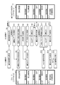
- FIG. 6 is a flowchart for explaining an example of data rewrite processing, and a diagram showing a memory configuration of storage on the tool side and a memory configuration of a flash ROM on the ECU side.
- FIG. 1 is a schematic view showing a data rewriting system of an electronic control unit for a car according to a first embodiment of the present invention.
- FIG. 3 is a diagram showing an example of a memory configuration of a flash ROM in FIG. 2;
- FIG. 6 is a flowchart for explaining an example of data rewrite processing, and
- FIG. 7 is a diagram showing states of storage, flash ROM and RAM before and during rewriting in the ENG control program to be rewritten.
- FIG. 7 is a diagram showing states of the flash ROM and the RAM during and after rewriting in the ENG control program to be rewritten.
- FIG. 13 is an explanatory view showing memory configurations before and after countermeasure in comparison with each other when the capacity of the rewrite area is over.
- FIG. 10 is a flowchart for explaining another example of the data rewrite process, and a diagram showing a memory configuration of storage on the tool side and a memory configuration of a flash ROM on the ECU side. It is a flowchart for demonstrating another example of a data rewriting process following FIG. 9A. It is a schematic diagram showing a data rewriting system in an electronic control unit for a car according to a second embodiment of the present invention.
- FIG. 1 shows an example of a data rewriting system which rewrites data of an electronic control unit (ECU: Electronic Control Unit) mounted on a vehicle.
- the ECU 10 to be rewritten is detachably connected to the tool 30 via a network cable 20 such as CAN (Controller Area Network), serial communication, FlexRay (registered trademark) and Ethernet (registered trademark).
- a network cable 20 such as CAN (Controller Area Network), serial communication, FlexRay (registered trademark) and Ethernet (registered trademark).
- the operator operates the tool 30 to rewrite the ECU 10.
- the ECU 10 and the tool 30 are not limited to wired using the network cable 20, and may be connected to each other by wireless communication using a wireless transceiver.
- the ECU 10 is an electronic device that controls various devices mounted on a vehicle, such as a fuel injection valve, a transmission, an electric brake system, an ABS (Antilock Brake System), a variable valve timing mechanism, and a brushless motor. It has a built-in computer. Specifically, as shown in FIG. 2, the ECU 10 includes a processor 11 such as a central processing unit (CPU), a communication device 12 for connecting to a network, a flash ROM 13 as an example of a non-volatile memory, and volatilization It has RAM (Random Access Memory) 14 as an example of sex memory, and bus 15. Here, the bus 15 mutually connects the processor 11, the communication device 12, the flash ROM 13 and the RAM 14. The communication device 12 also includes a connector (not shown) that detachably connects the network cable 20.
- a processor 11 such as a central processing unit (CPU)
- a communication device 12 for connecting to a network
- flash ROM 13 as an example of a non-volatile memory
- the storage area of the flash ROM 13 is divided into a plurality of erase blocks EB1 to EBq of a predetermined size, as shown in FIG.
- Each erase block EB1 to EBq is partitioned into a plurality of write blocks WB1, WB2,..., WBx of a predetermined size.
- the erase block defines the minimum unit for erasing data
- the write block defines the minimum unit for writing data
- the write block has the same or smaller capacity than the erase block. .
- an ENG (Engine) control program is stored in the storage area corresponding to the erase blocks EB1 to EBm of the flash ROM 13, and the surplus part is an empty area.
- Identification information for example, identification of new and old programs
- identification information for identifying each erase block is added to the start address of the erase block EB1.
- a hash value (hash value 1) is used in this example.
- the hash value is an example of identification information for comparing the identity of data, and it is preferable to adopt similar data that takes largely different values. Then, the processor 31 temporarily stores the hash value calculated from the data of the erase block EB1 in a storage medium such as a RAM in the processor 31.
- a TCU (Transmission Control Unit) control program is stored in the storage area corresponding to the erase blocks EBm + 1 to EBn, and the surplus portion is an empty area.
- Identification information for example, a hash value 2 for identifying the stored control program and the control program to be rewritten or identifying the respective erase blocks is given to the start address of the erase block EBm + 1.
- an API Application Programming Interface
- the surplus portion is an empty area.
- Identification information (for example, hash value 3) for identifying the stored control program and the control program to be rewritten or identifying the respective erase blocks is given to the top address of the erase block EBn + 1.
- a BIOS Basic Input Output System
- Identification information (for example, hash value 4) for identifying the stored control program and the control program to be rewritten or identifying the respective erasure blocks is given to the top address of the erasure block EBo + 1.
- the storage areas corresponding to the erase blocks EBp + 1 to EBq are common free areas (common areas). Identification information (for example, hash value 5) for identifying a free area or identifying each of the erase blocks is given to the top address of the erase block EBp + 1. As described above, various programs are stored in the flash ROM 13 for each storage area configured in units of integral multiples of the erase block.
- the tool 30 is an electronic device with which an operator performs data rewriting work of the ECU 10, and is configured of, for example, a personal computer.
- the tool 30 works with a processor 31 such as a CPU, a communication device 32 for connecting to a network, a storage 33 such as a hard disk drive or a solid state drive (SSD), It comprises an input / output device 34 serving as an interface to the user, and a bus 35 for interconnecting these devices.
- the communication device 32 includes a connector (not shown) for detachably connecting the network cable 20.
- the input / output device 34 also includes a display such as an LCD (Liquid Crystal Display), a keyboard, and a pointing device such as a mouse.
- the storage 33 may be, for example, storage of a NAS (Network Attached Storage) or a server connected to a network (not shown).
- the storage 33 stores rewrite data for rewriting the flash ROM 13 of the ECU 10.
- the rewrite data includes, for example, a control program for controlling various devices mounted on a vehicle, and control parameters such as constants and maps used in the control program.
- the rewrite data stored in the storage 33 is transferred to the communication device 32 through the bus 35 under the control of the processor 31 and transmitted to the ECU 10 from the connector (not shown) through the network cable 20.
- FIG. 5 shows an example of a procedure for updating a part of the control program of the flash ROM 13 of the ECU 10, the memory configuration of the storage on the tool side, and the memory configuration of the flash ROM on the ECU side.
- FIG. 6 shows the states of the storage, flash ROM and RAM before and during rewriting in the ENG control program to be rewritten.
- FIG. 7 shows the states of the flash ROM and the RAM during and after rewriting in the ENG control program to be rewritten.
- the data rewriting process is performed when the operator performs a predetermined operation in the tool 30 after the tool 30 is connected to the ECU 10 with the network cable 20.
- the ECU 10 is premised to be supplied with electric power and activated when connected to the tool 30 via the network cable 20, but may be activated by connection of another power cable.
- the storage 33 in the tool 30 has a memory configuration in which an ENG control program, a TCU control program, an API, a BIOS, and a free area are allocated as in FIG. 3.
- version 2 (Ver: 2) is granted.
- the software written in the flash ROM 13 in the ECU 10 has a memory configuration in which an ENG control program, a TCU control program, an API, a BIOS, and a free area are allocated as in FIG. Then, version 1 (Ver: 1) is assigned as identification information of the ENG control program, and version 2 (Ver: 2) is assigned as identification information to the TCU control program, API, BIOS and free space.
- FIG. 6A shows the ENG control program (Ver: 2) of the storage 33 on the tool 30 side and the ENG control program (Ver: 1) of the flash ROM 13 before rewriting on the ECU 10 side. There is free space in the surplus part.
- an identification information collation request is issued from the tool 30 to the ECU 10 (step S1), and identification information (here, software Ver: 2) stored in the storage 33 in the tool 30 and identification stored in the flash ROM 13 in the ECU 10
- the information (here, software Ver: 1) is compared by the ECU 10 (step S2). If there is a difference in the identification information, the ECU 10 makes a request to send the rewrite data to the tool 30 (step S3). As a result, the tool 30 outputs an erase request for the rewrite target (area) (step S4).
- the ECU 10 receives the deletion request from the tool 30, deletion of the rewrite target (area) is started (step S5).
- the ECU 10 notifies the tool 30 of the end of the erasing (step S6).
- write data (software Ver: 2 ENG control program) is transferred from the tool 30 to the ECU 10 (step S7), and the write data is stored in the RAM 14 (step S8).
- the ECU 10 determines whether there is a writing abnormality (step S10). If there is no difference in the identification information at step S2 and if it is determined at step S10 that "writing abnormality is not present", the ECU 10 notifies the tool 30 of writing completion (step S13), and the tool 30 completes writing When the notification is received, the writing completion is displayed on the display of the input / output device 34 to notify the worker (step S14). If there are a plurality of rewrite targets, an identification information collation request is issued for the next write target, and the process moves to the next rewrite target (step S15), and the same operation as the above-described step is repeated.
- step S10 determines whether write error has an error
- the erase block including the corresponding write block (abnormal portion) is erased (step S11).
- Rewriting is performed using the held data (step S12). During this erase and rewrite, external communication is not interrupted.
- the write data to the write blocks WBn + 1 to WBo-1 may be retransferred from the storage 33 of the tool 30 to the RAM 14 and written again.
- the ENG control program of the same version 2 as the storage 33 on the tool 30 side is written to the flash ROM 13 and updating from the old version to the new version finish.
- the tool 30 receives and monitors the busy signal output from the ECU 10 (step S16) to avoid communication timeout between the tool 30 and the ECU 10.
- the ECU 10 notifies the tool 30 of writing completion (step S13), and when the tool 30 receives the writing completion notification, the tool 30 displays it on the display of the input / output device 34 to notify the operator of writing completion (step S14). Then, if there are a plurality of rewrite targets, an identification information collation request is issued for the next write target, and the process moves to the next rewrite target (step S15), and the same operation as the above-described step is repeated.
- FIG. 8 shows a comparison of the memory configurations before and after the countermeasure when the amount of data to be written is larger than the amount of written data and the capacity of the rewrite area is over in the data rewriting process described above. ing.
- the flash ROM 13 has the same memory configuration as that shown in FIG. 3, and the case of rewriting the ENG control program will be described as an example.
- the ENG control program includes “function A call” and “function A main body”, and writes an additional ENG control program in the free space of this ENG control program. Shall be included.
- the additional ENG control program includes "function B call", "function B main body”, “function C call” and "function C main body”.
- the additional ENG control program has a larger capacity than the empty area and can not fit in the empty area, other control programs that do not need to be rewritten, for example, the TCU control program, API and BIOS must also sequentially rewrite the address and rewrite It does not.
- each control program area is used to secure the additional data capacity, but when a specific control program area overflows, (b) and (c) of FIG. As shown in), an arbitrary function call unit may be placed in the control program area, and the function body may be moved to a common free area.
- FIGS. 9A and 9B respectively show another example of the data rewriting process for updating a part of the control program of the flash ROM 13 of the ECU 10, in which a plurality of control programs are rewritten.
- the case where the ENG control program of the flash ROM 13 (the ECU 10 side) before rewriting is the old version and the case where the additional ENG control program is written in the common free space is taken as an example.
- an identification information collation request is issued from the tool 30 to the ECU 10 (step S21), and the identification information (here, software Ver: 2) stored in the storage 33 in the tool 30 and the identification stored in the flash ROM 13 in the ECU 10
- the information (here, software Ver: 1) is compared by the ECU 10 (step S22). If there is a difference in the identification information, the ECU 10 sends a request for sending the ENG control program, which is the rewrite data, to the tool 30 (step S23). As a result, the erasing request for rewriting is output from the tool 30 (step S24), and the ECU 10 starts erasing the ENG control program to be rewritten (step S25). Then, when the erasing is completed, the ECU 10 notifies the tool 30 of the end of the erasing (step S26).
- write data (software Ver: 2 ENG control program) is transferred from the tool 30 to the ECU 10 (step S27), and this data is stored in the RAM 14 (step S28).
- the ECU 10 determines whether there is a writing abnormality (step S30). If there is no difference in the identification information at step S22, or if it is determined at step S30 that there is no writing error, the ECU 10 notifies the tool 30 of writing completion (step S33), and the tool 30 completes writing.
- the identification information collation request is issued to the next writing object, and the rewriting operation of the common area which is the next rewriting object is started (step S35).
- step S30 determines whether "write error has occurred" or "write error has occurred"
- the erase block (error portion) in which the write error has occurred is erased (step S31), and the data saved in the error block to the RAM 14 is deleted.
- Rewrite using it step S32. That is, at the time of erase in erase block units in the flash ROM 13, data of the write block which is normally written is saved (copied) to the RAM 14 and then erased, and the remaining data which is not normally written Is received again and rewritten.
- the tool 30 receives and monitors the busy (BUSY) signal output from the ECU 10 (step S34), and communication timeout of the tool 30 and the ECU 10 is avoided.
- the ECU 10 notifies the tool 30 of the completion of the writing (step S33).
- the operation shifts to the rewrite operation of the common empty area (common area). That is, the identification information collation request is output from the tool 30 to the ECU 10 (step S35), and the identification information (here, software Ver: 2) stored in the storage 33 in the tool 30 and the identification stored in the flash ROM 13 in the ECU 10
- the information (here, software Ver: 1) is compared by the ECU 10 (step S36). If there is a difference in the identification information, the ECU 10 makes a request to send the rewrite data to the common area on the tool 30 (step S37). As a result, the erasing request of the common area to be rewritten is output from the tool 30 (step S38). Erasure of the common area to be rewritten is started on the ECU 10 side (step S39), and when erasure is completed, the ECU 10 notifies the tool 30 side of the termination of erasure (step S40).
- write data (an additional ENG control program) is transferred from the tool 30 to the ECU 10 (step S41), and this data is stored in the RAM 14 (step S42).
- the data writing to the RAM 14 is completed, the data writing from the RAM 14 to the flash ROM 13 is performed (step S43).
- the presence or absence of write abnormality is determined, and when write is completed, an identification information collation request is issued for the next write target, and it moves to the next rewrite target. Repeat the operation to write.
- the ECU 10 notifies the tool 30 that all writing has been completed, the writing completion is displayed on the display of the input / output device 34 to notify the operator.
- FIG. 10 shows a data rewriting system in an electronic control unit for a car according to a second embodiment of the present invention.
- the rewriting tool 40 is mounted on the non-volatile memory (flash ROM) 45 mounted on the first ECU 43 mounted on the automobile 42 or the second ECU 44 by wireless communication using the wireless transceiver 41.
- the non-volatile memory (flash ROM) 46 is configured to be rewritten.
- a wireless transceiver 47 and a security gateway 48 for preventing unauthorized access are mounted on the automobile 42, and the data received by the wireless transceiver 47 is transmitted from the security gateway 48 via the bus 49 to the first ECU 43 and the second ECU 44.
- Is configured to input here, for convenience, they will be referred to as the first ECU 43 and the second ECU 44, but basically the two have the same configuration, there is no relationship or priority between master and slave, and substantially the same nonvolatile memory 45, 46, eg, flash ROM, CPUs 50 and 51 are provided.
- the data received from the rewriting tool 40 is supplied to the non-volatile memory 46 of the second ECU 44 when the data is sent. Then, the control program is rewritten.
- the specific rewriting procedure is as described above. Then, switching of the first ECU 43 and the second ECU 44 is performed while the automobile 42 is stopped. That is, control of the automobile 42 is performed by the second ECU 44.
- the vehicle 42 is controlled by the reprogrammed new control program.
- the other basic rewriting operation is the same as that of the first embodiment, so the detailed description will be omitted. Since there is a possibility that the automobile 42 may be moved in data rewriting by wireless, it is preferable to narrow the rewriting target range and shorten the rewriting time as compared with the case of connecting by the network cable 20. That is, data to be written to the non-volatile memory may be input by wireless communication with the range to be rewritten limited.
- the control program is basically stored in the non-volatile memory for each storage area configured in units of integral multiples of the erase block, and control is performed in the same manner as in the first embodiment. Since the program allocation and the erase block correspond to each other, the rewrite target area can be set for each control program, and the data transfer amount can be reduced to shorten the software update time. Further, in response to an external rewrite request, a part of the storage area of the non-volatile memory is erased, and writing in this erase area in units of write blocks can reduce the size of the rewrite target area. The write time can be shortened to shorten the software update time. Furthermore, erroneous writing can be suppressed by preventing external communication from being interrupted during erasing and rewriting.
- the configuration may be such that one ECU switches and rewrites two flash ROMs.
- the present invention can be applied to a configuration in which three or more ECUs and a flash ROM are switched and used.
- rewrite data transferred from the rewrite tool 40 is stored in advance in the storage device. It is also possible to configure the non-volatile memory to be rewritten using the data stored in.
Abstract
An objective of the present invention is to provide an electronic control device for automobile capable of reducing an update time of software stored in a nonvolatile memory. This electronic control device for automobile comprises a nonvolatile memory in which data can be deleted in deletion block units and data can be written in writing block units which are the same as or smaller than the deletion blocks, a control program being stored in each of storage regions configured in units of integer multiples of the deletion blocks in the nonvolatile memory, and the device is characterized in that when, in response to an external overwrite request, a portion of the data in the nonvolatile memory is deleted in the deletion block units and the data is written to the nonvolatile memory in the write block units, an overwrite error check is carried out for each of the blocks.
Description
本発明は、自動車用電子制御装置及びその制御方法に関し、更に詳しくは、自動車に搭載されたECU(Electric Control Unit)における制御ソフトウェアの更新技術に関する。
The present invention relates to an electronic control device for a vehicle and a control method thereof, and more particularly to a technology for updating control software in an ECU (Electric Control Unit) mounted on a vehicle.
従来、この種の電子制御装置において、フラッシュROM(Read Only Memory)などの不揮発性メモリに書込まれたプログラムやデータを書換えて更新する場合には、例えば特許文献1に記載されるような方法で行っていた。すなわち、電子制御装置に接続されたツール(メモリ書換機)からの指示に応答して、不揮発性メモリの対象領域を消去し、ツールから順次送信されるプログラムやデータを不揮発性メモリに書込んでいた。
Conventionally, in a case where a program or data written in a non-volatile memory such as a flash ROM (Read Only Memory) is rewritten and updated in this type of electronic control device, a method as described in Patent Document 1, for example I was going there. That is, in response to an instruction from a tool (memory rewriter) connected to the electronic control device, the target area of the non-volatile memory is erased, and a program or data sequentially transmitted from the tool is written to the non-volatile memory. It was.
ところで、近年、自動車用電子制御装置に搭載される制御ソフトウェアの規模は増大の一途を辿っており、これに伴ってプログラムやデータの更新のための書換え時間が長大化している。現状の通信技術では、例えば4Mbyteの記憶容量の書換えには25分程度の時間が必要になる。今後、更に不揮発性メモリの記憶容量や制御ソフトウェアの規模が増大することを考えると、更新にはより長時間を要することになる。
By the way, in recent years, the scale of control software installed in electronic control devices for automobiles has been steadily increasing, and along with this, the rewriting time for updating programs and data has become longer. In the current communication technology, for example, about 25 minutes are required to rewrite the storage capacity of 4 Mbytes. Considering that the storage capacity of the non-volatile memory and the scale of the control software will further increase in the future, the update will take longer.
本発明は上記のような事情に鑑みてなされたもので、その目的とするところは、不揮発性メモリに記憶されたソフトウェアの更新時間を短縮できる自動車用電子制御装置及びその制御方法を提供することにある。
The present invention has been made in view of the above circumstances, and it is an object of the present invention to provide an electronic control apparatus for a vehicle capable of shortening the update time of software stored in a non-volatile memory and a control method thereof. It is in.
本発明の一態様に係る自動車用電子制御装置は、消去ブロック単位でデータを消去可能であると共に、前記消去ブロックと同一又は小さい書込ブロック単位でデータを書込み可能な不揮発性メモリを有し、該不揮発性メモリにおける消去ブロックの整数倍の単位で構成された記憶領域毎に制御プログラムが記憶された自動車用電子制御装置であって、外部からの書換え要求に応じて、前記不揮発性メモリの一部のデータを消去ブロック単位で消去し、前記不揮発性メモリに書込ブロック単位でデータを書込む際に、該ブロック毎に書換えの正誤を確認するプロセッサを備える、ことを特徴とする。
The electronic control unit for a motor vehicle according to one aspect of the present invention has a non-volatile memory capable of erasing data in erase block units and writing data in write block units identical or smaller than the erase block. An electronic control unit for a motor vehicle in which a control program is stored for each storage area configured in units of integral multiples of erase blocks in the nonvolatile memory, the non-volatile memory corresponding to an external rewrite request. A processor is provided which erases the data of a part in an erase block unit and, when writing the data in a write block unit in the non-volatile memory, comprises a processor for confirming rewriting correctness / incorrectness for each block.
また、本発明の一態様に係る自動車用電子制御装置の制御方法は、消去ブロック単位でデータを消去可能であると共に、前記消去ブロックと同一又は小さい書込ブロック単位でデータを書込み可能な不揮発性メモリを有し、該不揮発性メモリにおける消去ブロックの整数倍の単位で構成された記憶領域毎に制御プログラムが記憶された自動車用電子制御装置の制御方法であって、外部からの書換え要求に応じて、前記不揮発性メモリの一部のデータを消去ブロック単位で消去し、前記不揮発性メモリに書込ブロック単位でデータを書込む際に、該ブロック毎に書換えの正誤を確認する、ことを特徴とする。
The control method of the electronic control unit for a motor vehicle according to one aspect of the present invention is non-volatile, capable of erasing data in erase block units and writing data in write block units identical or smaller than the erase block. A control method of an electronic control unit for a motor vehicle having a memory and storing a control program for each storage area configured in units of integral multiples of erase blocks in the non-volatile memory, the control method according to an external rewrite request. And erase the partial data of the non-volatile memory in erase block units, and when writing the data in the non-volatile memory in write block units, check whether the rewriting is correct or not for each of the blocks. I assume.
本発明によれば、不揮発性メモリに、消去ブロックの整数倍の単位で構成された記憶領域毎に制御プログラムを記憶し、制御プログラムの割り付けと消去ブロックを対応させているので、書換え対象領域を制御プログラム毎にでき、データの転送量を削減してソフトウェアの更新時間を短縮できる。
また、外部からの書換え要求に応じて、不揮発性メモリの一部の記憶領域を消去し、この消去領域に書込ブロック単位で書込むことで、書換え対象領域のサイズの縮小を図れ、データの書込み時間を短縮してソフトウェアの更新時間を短縮できる。 According to the present invention, the control program is stored in the non-volatile memory for each storage area configured in units of integral multiples of the erase block, and the assignment of the control program corresponds to the erase block. This can be done for each control program, and the amount of data transfer can be reduced to shorten the software update time.
Further, in response to an external rewrite request, a part of the storage area of the non-volatile memory is erased, and writing in this erase area in units of write blocks can reduce the size of the rewrite target area. The write time can be shortened to shorten the software update time.
以下、本発明の実施形態について図面を参照して説明する。
図1は、自動車に搭載される電子制御装置(ECU:Electronic Control Unit)のデータを書換える、データ書換えシステムの一例を示している。書換え対象となるECU10は、CAN(Controller Area Network)、シリアル通信、FlexRay(登録商標)及びEthernet(登録商標)などのネットワークケーブル20を介して、ツール30に着脱自在に接続される。そして、作業者がツール30を操作して、ECU10の書換え作業を行う。
なお、ECU10とツール30とは、ネットワークケーブル20を使用した有線に限らず、無線送受信機を使用した無線通信によって相互に接続されるようにしてもよい。 Hereinafter, embodiments of the present invention will be described with reference to the drawings.
FIG. 1 shows an example of a data rewriting system which rewrites data of an electronic control unit (ECU: Electronic Control Unit) mounted on a vehicle. The ECU 10 to be rewritten is detachably connected to thetool 30 via a network cable 20 such as CAN (Controller Area Network), serial communication, FlexRay (registered trademark) and Ethernet (registered trademark). Then, the operator operates the tool 30 to rewrite the ECU 10.
The ECU 10 and thetool 30 are not limited to wired using the network cable 20, and may be connected to each other by wireless communication using a wireless transceiver.
図1は、自動車に搭載される電子制御装置(ECU:Electronic Control Unit)のデータを書換える、データ書換えシステムの一例を示している。書換え対象となるECU10は、CAN(Controller Area Network)、シリアル通信、FlexRay(登録商標)及びEthernet(登録商標)などのネットワークケーブル20を介して、ツール30に着脱自在に接続される。そして、作業者がツール30を操作して、ECU10の書換え作業を行う。
なお、ECU10とツール30とは、ネットワークケーブル20を使用した有線に限らず、無線送受信機を使用した無線通信によって相互に接続されるようにしてもよい。 Hereinafter, embodiments of the present invention will be described with reference to the drawings.
FIG. 1 shows an example of a data rewriting system which rewrites data of an electronic control unit (ECU: Electronic Control Unit) mounted on a vehicle. The ECU 10 to be rewritten is detachably connected to the
The ECU 10 and the
ECU10は、自動車に搭載された各種の機器、例えば燃料噴射弁、変速機、電動ブレーキシステム、ABS(Antilock Brake System)、可変バルブタイミング機構、及びブラシレスモータなどを制御する電子機器であって、マイクロコンピュータを内蔵している。具体的には、ECU10は、図2に示すように、CPU(Central Processing Unit)などのプロセッサ11と、ネットワークに接続するための通信装置12と、不揮発性メモリの一例としてのフラッシュROM13と、揮発性メモリの一例としてのRAM(Random Access Memory)14と、バス15とを有する。ここで、バス15は、プロセッサ11、通信装置12、フラッシュROM13及びRAM14を相互に接続している。また、通信装置12は、ネットワークケーブル20を着脱可能に接続するコネクタ(図示せず)を備える。
The ECU 10 is an electronic device that controls various devices mounted on a vehicle, such as a fuel injection valve, a transmission, an electric brake system, an ABS (Antilock Brake System), a variable valve timing mechanism, and a brushless motor. It has a built-in computer. Specifically, as shown in FIG. 2, the ECU 10 includes a processor 11 such as a central processing unit (CPU), a communication device 12 for connecting to a network, a flash ROM 13 as an example of a non-volatile memory, and volatilization It has RAM (Random Access Memory) 14 as an example of sex memory, and bus 15. Here, the bus 15 mutually connects the processor 11, the communication device 12, the flash ROM 13 and the RAM 14. The communication device 12 also includes a connector (not shown) that detachably connects the network cable 20.
フラッシュROM13の記憶領域は、図3に示すように、所定サイズの複数の消去ブロックEB1~EBqに分割されている。また、各々の消去ブロックEB1~EBqは、所定サイズの複数の書込ブロックWB1,WB2,…,WBxに区画されている。ここで、消去ブロックは、データを消去する最小単位を規定し、書込ブロックはデータを書込む最小単位を規定しており、書込ブロックは消去ブロックと同一か、又は小さい容量になっている。そして、ある書込ブロックのデータを書換える場合、その書込ブロックが属する消去ブロックのデータを全て消去した後、データを消去した消去ブロックに属する全ての書込ブロックにデータを書込む、という手順を経るようになっている。なお、フラッシュROM13における消去ブロックのサイズが同一でない場合には、各消去ブロックに属する書込ブロックの数は異なっていてもよい。
The storage area of the flash ROM 13 is divided into a plurality of erase blocks EB1 to EBq of a predetermined size, as shown in FIG. Each erase block EB1 to EBq is partitioned into a plurality of write blocks WB1, WB2,..., WBx of a predetermined size. Here, the erase block defines the minimum unit for erasing data, the write block defines the minimum unit for writing data, and the write block has the same or smaller capacity than the erase block. . Then, when rewriting data of a certain write block, after erasing all data of the erase block to which the write block belongs, the procedure of writing the data to all the write blocks belonging to the erase block from which the data is erased It is supposed to go through. If the size of the erase block in the flash ROM 13 is not the same, the number of write blocks belonging to each erase block may be different.
フラッシュROM13の消去ブロックEB1~EBmに対応する記憶領域には、例えばENG(エンジン)制御プログラムが記憶されており、余剰部分が空き領域となっている。消去ブロックEB1の先頭アドレスには、記憶されている制御プログラムと書換える制御プログラムとを識別(例えば新旧プログラムの識別)、または前記各消去ブロックを識別するための識別情報が付与されている。識別情報としては、本例ではハッシュ値(ハッシュ値1)を用いている。
For example, an ENG (Engine) control program is stored in the storage area corresponding to the erase blocks EB1 to EBm of the flash ROM 13, and the surplus part is an empty area. Identification information (for example, identification of new and old programs) or identification information for identifying each erase block is added to the start address of the erase block EB1. As identification information, a hash value (hash value 1) is used in this example.
このハッシュ値は、データの同一性を比較するための識別情報の一例であって、類似するデータでも大きく異なる値をとるものを採用するとよい。そして、プロセッサ31は、消去ブロックEB1のデータから算出したハッシュ値を、プロセッサ31内のRAMなどの記憶媒体に一時的に記憶させておく。
The hash value is an example of identification information for comparing the identity of data, and it is preferable to adopt similar data that takes largely different values. Then, the processor 31 temporarily stores the hash value calculated from the data of the erase block EB1 in a storage medium such as a RAM in the processor 31.
消去ブロックEBm+1~EBnに対応する記憶領域には、例えばTCU(Transmission Control Unit)制御プログラムが記憶されており、余剰部分が空き領域となっている。消去ブロックEBm+1の先頭アドレスには、記憶されている制御プログラムと書換える制御プログラムとを識別、または前記各消去ブロックを識別するための識別情報(例えばハッシュ値2)が付与されている。
For example, a TCU (Transmission Control Unit) control program is stored in the storage area corresponding to the erase blocks EBm + 1 to EBn, and the surplus portion is an empty area. Identification information (for example, a hash value 2) for identifying the stored control program and the control program to be rewritten or identifying the respective erase blocks is given to the start address of the erase block EBm + 1.
消去ブロックEBn+1~EBoに対応する記憶領域には、例えばAPI(Application Programming Interface)が記憶されており、余剰部分が空き領域となっている。消去ブロックEBn+1の先頭アドレスには、記憶されている制御プログラムと書換える制御プログラムとを識別、または前記各消去ブロックを識別するための識別情報(例えばハッシュ値3)が付与されている。
消去ブロックEBo+1~EBpに対応する記憶領域には、例えばBIOS(Basic Input Output System)が記憶されており、余剰部分が空き領域となっている。消去ブロックEBo+1の先頭アドレスには、記憶されている制御プログラムと書換える制御プログラムとを識別、または前記各消去ブロックを識別するための識別情報(例えばハッシュ値4)が付与されている。 For example, an API (Application Programming Interface) is stored in the storage area corresponding to the erase block EBn + 1 to EBo, and the surplus portion is an empty area. Identification information (for example, hash value 3) for identifying the stored control program and the control program to be rewritten or identifying the respective erase blocks is given to the top address of the erase block EBn + 1.
For example, a BIOS (Basic Input Output System) is stored in the storage area corresponding to the erase block EBo + 1 to EBp, and the surplus portion is an empty area. Identification information (for example, hash value 4) for identifying the stored control program and the control program to be rewritten or identifying the respective erasure blocks is given to the top address of the erasure block EBo + 1.
消去ブロックEBp+1~EBqに対応する記憶領域は、共通の空き領域(共通領域)となっている。消去ブロックEBp+1の先頭アドレスには、空き領域を識別、または前記各消去ブロックを識別するための識別情報(例えばハッシュ値5)が付与されている。
このように、フラッシュROM13には、消去ブロックの整数倍の単位で構成された記憶領域毎に各種のプログラムが記憶されている。 The storage areas corresponding to the erase blocks EBp + 1 to EBq are common free areas (common areas). Identification information (for example, hash value 5) for identifying a free area or identifying each of the erase blocks is given to the top address of the erase block EBp + 1.
As described above, various programs are stored in theflash ROM 13 for each storage area configured in units of integral multiples of the erase block.
このように、フラッシュROM13には、消去ブロックの整数倍の単位で構成された記憶領域毎に各種のプログラムが記憶されている。 The storage areas corresponding to the erase blocks EBp + 1 to EBq are common free areas (common areas). Identification information (for example, hash value 5) for identifying a free area or identifying each of the erase blocks is given to the top address of the erase block EBp + 1.
As described above, various programs are stored in the
ツール30は、作業者がECU10のデータ書換え作業を行う電子機器であって、例えば、パーソナルコンピュータなどから構成される。具体的には、ツール30は、図4に示すように、CPUなどのプロセッサ31と、ネットワークに接続するための通信装置32と、ハードディスク装置やSSD(Solid State Drive)などのストレージ33と、作業者へのインターフェースとなる入出力装置34と、これらの機器を相互に接続するバス35とを備えている。ここで、通信装置32は、ネットワークケーブル20を着脱可能に接続するコネクタ(図示せず)を備える。また、入出力装置34は、LCD(Liquid Crystal Display)などのディスプレイと、キーボードと、マウスなどのポインティングデバイスと、を含む。なお、ストレージ33は、例えば、図示しないネットワークに接続されたNAS(Network Attached Storage)やサーバのストレージなどであってもよい。
The tool 30 is an electronic device with which an operator performs data rewriting work of the ECU 10, and is configured of, for example, a personal computer. Specifically, as shown in FIG. 4, the tool 30 works with a processor 31 such as a CPU, a communication device 32 for connecting to a network, a storage 33 such as a hard disk drive or a solid state drive (SSD), It comprises an input / output device 34 serving as an interface to the user, and a bus 35 for interconnecting these devices. Here, the communication device 32 includes a connector (not shown) for detachably connecting the network cable 20. The input / output device 34 also includes a display such as an LCD (Liquid Crystal Display), a keyboard, and a pointing device such as a mouse. The storage 33 may be, for example, storage of a NAS (Network Attached Storage) or a server connected to a network (not shown).
ストレージ33には、ECU10のフラッシュROM13を書換えるための書換えデータが格納されている。書換えデータは、例えば、自動車に搭載された各種機器を制御する制御プログラム、その制御プログラムで使用される定数やマップなどの制御パラメータなどを含む。ストレージ33に格納された書換えデータは、プロセッサ31の制御によりバス35を介して通信装置32に転送され、図示しないコネクタからネットワークケーブル20を介してECU10に送信される。
The storage 33 stores rewrite data for rewriting the flash ROM 13 of the ECU 10. The rewrite data includes, for example, a control program for controlling various devices mounted on a vehicle, and control parameters such as constants and maps used in the control program. The rewrite data stored in the storage 33 is transferred to the communication device 32 through the bus 35 under the control of the processor 31 and transmitted to the ECU 10 from the connector (not shown) through the network cable 20.
次に、上記のような構成において、データ書換え処理(リプログラミング)について図5乃至図7により説明する。図5は、ECU10のフラッシュROM13の制御プログラムの一部を更新する手順の一例と、ツール側のストレージのメモリ構成とECU側のフラッシュROMのメモリ構成を示している。また、図6は、書換え対象のENG制御プログラムにおける書換え前と書換え中のストレージ、フラッシュROM及びRAMの状態をそれぞれ示す。図7は、書換え対象のENG制御プログラムにおける書換え中と書換え後のフラッシュROM及びRAMの状態を示す。
Next, data rewriting processing (reprogramming) in the configuration as described above will be described with reference to FIGS. FIG. 5 shows an example of a procedure for updating a part of the control program of the flash ROM 13 of the ECU 10, the memory configuration of the storage on the tool side, and the memory configuration of the flash ROM on the ECU side. FIG. 6 shows the states of the storage, flash ROM and RAM before and during rewriting in the ENG control program to be rewritten. FIG. 7 shows the states of the flash ROM and the RAM during and after rewriting in the ENG control program to be rewritten.
データ書換え処理は、作業者がツール30をネットワークケーブル20でECU10に接続した後、ツール30において、所定の操作を行ったときに実行される。ここでは、ECU10は、ネットワークケーブル20を介してツール30と接続されたときに、電力が供給されて起動することを前提とするが、別の電源ケーブルの接続により起動する形態もあり得る。
The data rewriting process is performed when the operator performs a predetermined operation in the tool 30 after the tool 30 is connected to the ECU 10 with the network cable 20. Here, the ECU 10 is premised to be supplied with electric power and activated when connected to the tool 30 via the network cable 20, but may be activated by connection of another power cable.
ツール30におけるストレージ33は、図3と同様にENG制御プログラム、TCU制御プログラム、API、BIOS及び空き領域が割り付けられたメモリ構成になっており、本例では各々の識別情報としてバージョン2(Ver:2)が付与されている。また、ECU10におけるフラッシュROM13に書込まれているソフトウェアは、図3と同様にENG制御プログラム、TCU制御プログラム、API、BIOS及び空き領域が割り付けられたメモリ構成になっている。そして、ENG制御プログラムの識別情報としてバージョン1(Ver:1)が付与され、TCU制御プログラム、API、BIOS及び空き領域には識別情報としてバージョン2(Ver:2)が付与されている。
The storage 33 in the tool 30 has a memory configuration in which an ENG control program, a TCU control program, an API, a BIOS, and a free area are allocated as in FIG. 3. In this example, version 2 (Ver: 2) is granted. Further, the software written in the flash ROM 13 in the ECU 10 has a memory configuration in which an ENG control program, a TCU control program, an API, a BIOS, and a free area are allocated as in FIG. Then, version 1 (Ver: 1) is assigned as identification information of the ENG control program, and version 2 (Ver: 2) is assigned as identification information to the TCU control program, API, BIOS and free space.
このように、本データ書換えシステムは、新旧の制御プログラムを比較し、バージョンが異なるブロックのみを書換える。これによって、フラッシュROM13に書込まれている旧バージョン1のENG制御プログラムが、ストレージ33における新バージョン2のENG制御プログラムに書換えられることになる。
図6の(a)は、ツール30側のストレージ33のENG制御プログラム(Ver:2)と、ECU10側の書換え前のフラッシュROM13のENG制御プログラム(Ver:1)を示しており、フラッシュROM13は余剰部分に空き領域を有している。 Thus, the data rewriting system compares new and old control programs, and rewrites only blocks having different versions. As a result, theold version 1 ENG control program written in the flash ROM 13 is rewritten to the new version 2 ENG control program in the storage 33.
FIG. 6A shows the ENG control program (Ver: 2) of thestorage 33 on the tool 30 side and the ENG control program (Ver: 1) of the flash ROM 13 before rewriting on the ECU 10 side. There is free space in the surplus part.
図6の(a)は、ツール30側のストレージ33のENG制御プログラム(Ver:2)と、ECU10側の書換え前のフラッシュROM13のENG制御プログラム(Ver:1)を示しており、フラッシュROM13は余剰部分に空き領域を有している。 Thus, the data rewriting system compares new and old control programs, and rewrites only blocks having different versions. As a result, the
FIG. 6A shows the ENG control program (Ver: 2) of the
まず、ツール30からECU10に識別情報照合要求が出され(ステップS1)、ツール30におけるストレージ33に記憶されている識別情報(ここではソフトVer:2)とECU10におけるフラッシュROM13に記憶されている識別情報(ここではソフトVer:1)とがECU10で比較される(ステップS2)。識別情報に差異があった場合は、ECU10側からツール30側に書換えデータの送付要求を行う(ステップS3)。これによって、ツール30から書換え対象(領域)の消去要求が出力される(ステップS4)。ECU10がツール30からの消去要求を受け取ると、書換え対象(領域)の消去が開始される(ステップS5)。そして、消去が終了すると、ECU10側からツール30側に消去終了を通知する(ステップS6)。
First, an identification information collation request is issued from the tool 30 to the ECU 10 (step S1), and identification information (here, software Ver: 2) stored in the storage 33 in the tool 30 and identification stored in the flash ROM 13 in the ECU 10 The information (here, software Ver: 1) is compared by the ECU 10 (step S2). If there is a difference in the identification information, the ECU 10 makes a request to send the rewrite data to the tool 30 (step S3). As a result, the tool 30 outputs an erase request for the rewrite target (area) (step S4). When the ECU 10 receives the deletion request from the tool 30, deletion of the rewrite target (area) is started (step S5). When the erasing is completed, the ECU 10 notifies the tool 30 of the end of the erasing (step S6).
次に、ツール30からECU10に書込みデータ(ソフトVer:2のENG制御プログラム)が転送され(ステップS7)、この書込みデータがRAM14に格納される(ステップS8)。RAM14へのデータの書込みが終了すると(ステップS9)、ECU10により書込み異常の有無が判定される(ステップS10)。上記ステップS2で識別情報に差異がなかった場合、及びステップS10で「書込み異常なし」と判定された場合には、ECU10からツール30に書込み完了を通知し(ステップS13)、ツール30が書込み完了通知を受け取ると入出力装置34のディスプレイに書込み完了を表示して作業者に通知する(ステップS14)。複数の書換え対象がある場合には、次の書込み対象に対して識別情報照合要求を出して、次の書換え対象へ移動し(ステップS15)、上述したステップと同様な動作を繰り返す。
Next, write data (software Ver: 2 ENG control program) is transferred from the tool 30 to the ECU 10 (step S7), and the write data is stored in the RAM 14 (step S8). When the writing of data to the RAM 14 is completed (step S9), the ECU 10 determines whether there is a writing abnormality (step S10). If there is no difference in the identification information at step S2 and if it is determined at step S10 that "writing abnormality is not present", the ECU 10 notifies the tool 30 of writing completion (step S13), and the tool 30 completes writing When the notification is received, the writing completion is displayed on the display of the input / output device 34 to notify the worker (step S14). If there are a plurality of rewrite targets, an identification information collation request is issued for the next write target, and the process moves to the next rewrite target (step S15), and the same operation as the above-described step is repeated.
一方、ステップS10で「書込み異常あり」、すなわち、書込みデータに誤りがあると判定された場合には、該当する書込ブロック(異常部)を含む消去ブロックを消去し(ステップS11)、RAM14に保持されているデータを使って再書込みを行う(ステップS12)。この消去及び再書込み中には、外部からの通信を途絶させないようにする。
On the other hand, if it is determined in step S10 that "write error", that is, it is determined that write data has an error, the erase block including the corresponding write block (abnormal portion) is erased (step S11). Rewriting is performed using the held data (step S12). During this erase and rewrite, external communication is not interrupted.
例えば、図6の(b)に示すように、書換え後のフラッシュROM13において、消去ブロックEB3中の書込ブロックWBoに書込み失敗エリアが発生したと仮定する。この場合には、図7の(a)に示すように、正常に書換えが完了した消去ブロックEB1,EB2のデータは保持し、消去ブロックEB3のみを消去し(このとき消去ブロックEB4は消去状態)、書込ブロックWBn+1~WBo、WBo+1~WBpに対して再書込みする。同様に、消去ブロックEB4中の書込ブロックに書込み失敗エリアが発生した場合には、消去ブロックEB4のみを消去し、書込ブロックWBo+1~WBpに対して再書込みする。
For example, as shown in (b) of FIG. 6, it is assumed that a write failure area occurs in the write block WBo in the erase block EB3 in the flash ROM 13 after rewriting. In this case, as shown in (a) of FIG. 7, the data of erase blocks EB1 and EB2 for which rewriting has been completed normally is held, and only erase block EB3 is erased (at this time, erase block EB4 is in the erased state). Write blocks WBn + 1 to WBo and WBo + 1 to WBp are rewritten. Similarly, when a write failure area occurs in the write block in the erase block EB4, only the erase block EB4 is erased and the write blocks WBo + 1 to WBp are rewritten.
この際、フラッシュROM13の書込ブロックWBn+1~WBo-1に書込まれているデータをRAM14に退避することで、再書込みする場合にRAM14のデータを利用して短時間で書き込むことができる。すなわち、フラッシュROM13における消去ブロック単位での消去の際に、正常に書込まれている書込ブロックのデータをRAM14に退避(コピー)してから消去し、正常に書込まれなかった残りのデータをツール30から再受信して書換えを行う。
At this time, by saving the data written in the write blocks WBn + 1 to WBo-1 of the flash ROM 13 in the RAM 14, it is possible to write in a short time using the data in the RAM 14 when rewriting. That is, at the time of erase in erase block units in the flash ROM 13, data of the write block which is normally written is saved (copied) to the RAM 14 and then erased, and the remaining data which is not normally written Are received again from the tool 30 to perform rewriting.
また、書込ブロックWBn+1~WBo-1への書込データを、ツール30のストレージ33からRAM14に再転送してもう一度書込みするようにしてもよい。リトライによる書込みが完了すると、図7の(b)に示すように、フラッシュROM13にはツール30側のストレージ33と同じバージョン2のENG制御プログラムが書込まれ、旧バージョンから新バージョンへの更新が終了する。
Alternatively, the write data to the write blocks WBn + 1 to WBo-1 may be retransferred from the storage 33 of the tool 30 to the RAM 14 and written again. When writing by retry is completed, as shown in (b) of FIG. 7, the ENG control program of the same version 2 as the storage 33 on the tool 30 side is written to the flash ROM 13 and updating from the old version to the new version finish.
上記ステップS11,S12の期間には、ツール30側でECU10から出力されるビジィ(BUSY)信号を受信して監視し(ステップS16)、ツール30とECU10の通信タイムアウトを回避する。書込みが完了すると、ECU10からツール30に書込み完了を通知し(ステップS13)、ツール30側で書込み完了通知を受け取ると入出力装置34のディスプレイに表示して作業者に書込み完了を通知する(ステップS14)。そして、複数の書換え対象がある場合には、次の書込み対象に対して識別情報照合要求を出して、次の書換え対象へ移動し(ステップS15)、上述したステップと同様な動作を繰り返す。
During the above steps S11 and S12, the tool 30 receives and monitors the busy signal output from the ECU 10 (step S16) to avoid communication timeout between the tool 30 and the ECU 10. When writing is completed, the ECU 10 notifies the tool 30 of writing completion (step S13), and when the tool 30 receives the writing completion notification, the tool 30 displays it on the display of the input / output device 34 to notify the operator of writing completion (step S14). Then, if there are a plurality of rewrite targets, an identification information collation request is issued for the next write target, and the process moves to the next rewrite target (step S15), and the same operation as the above-described step is repeated.
なお、上記実施形態では、書換え対象の識別情報を順次比較して書換えの要否を判定する例を示した。このようにしているのは、無線通信でリプログラムする場合を考慮したもので、無線通信では不特定多数の車両が対象となるため、相手側の車両がどのような状態になっているか把握できていないままリプログラムが行われることがあるからである。特に、過去何度かリプログラムされている状態から最新のプログラムに変更する場合には、どこがリプログラムされているのか分からない。
しかしながら、書換え対象が明確な場合には、ツール30からECU10に書換え対象の制御プログラム、消去ブロック、あるいは書込ブロックを指定して、ブロック単位で書換えるようにしても良い。すなわち、不揮発性メモリの書換えを実行する消去ブロックを予め設定し、当該消去ブロック内の書込ブロックを書換えるようにすることもできる。 In the above embodiment, an example has been shown in which identification information to be rewritten is sequentially compared to determine whether or not rewriting is necessary. In this way, the case of reprogramming by wireless communication is taken into consideration, and since an unspecified number of vehicles are targeted in wireless communication, it is possible to grasp what state the other vehicle is in. Reprogramming may take place without In particular, when changing from the state of being reprogrammed several times in the past to the latest program, it is not known where it has been reprogrammed.
However, when the object to be rewritten is clear, the control program, the erase block or the write block to be rewritten may be designated from thetool 30 to the ECU 10 and the block may be rewritten. That is, an erase block for executing rewriting of the non-volatile memory can be set in advance, and the write block in the erase block can be rewritten.
しかしながら、書換え対象が明確な場合には、ツール30からECU10に書換え対象の制御プログラム、消去ブロック、あるいは書込ブロックを指定して、ブロック単位で書換えるようにしても良い。すなわち、不揮発性メモリの書換えを実行する消去ブロックを予め設定し、当該消去ブロック内の書込ブロックを書換えるようにすることもできる。 In the above embodiment, an example has been shown in which identification information to be rewritten is sequentially compared to determine whether or not rewriting is necessary. In this way, the case of reprogramming by wireless communication is taken into consideration, and since an unspecified number of vehicles are targeted in wireless communication, it is possible to grasp what state the other vehicle is in. Reprogramming may take place without In particular, when changing from the state of being reprogrammed several times in the past to the latest program, it is not known where it has been reprogrammed.
However, when the object to be rewritten is clear, the control program, the erase block or the write block to be rewritten may be designated from the
図8は、上述したデータ書換え処理において、書込むデータ量が書込まれているデータ量よりも多く、書換え領域の容量がオーバーした場合における、対策前と対策後のメモリ構成を対比して示している。ここでは、図8の(a)に示すように、フラッシュROM13が図3に示したメモリ構成と同じであると仮定し、ENG制御プログラムを書換える場合を例に取って説明する。図8の(b)に示すように、ENG制御プログラムには、「関数Aコール」と「関数A本体」が含まれており、このENG制御プログラムの空き領域に追加分のENG制御プログラムを書込むものとする。ここで、追加分のENG制御プログラムには「関数Bコール」、「関数B本体」、「関数Cコール」及び「関数C本体」が含まれている。追加分のENG制御プログラムが空き領域より容量が大きく、空き領域に収まらない場合には、書換える必要がない他の制御プログラム、例えばTCU制御プログラム、API及びBIOSもアドレスを順次ずらして書換えなければならない。
FIG. 8 shows a comparison of the memory configurations before and after the countermeasure when the amount of data to be written is larger than the amount of written data and the capacity of the rewrite area is over in the data rewriting process described above. ing. Here, as shown in FIG. 8A, it is assumed that the flash ROM 13 has the same memory configuration as that shown in FIG. 3, and the case of rewriting the ENG control program will be described as an example. As shown in (b) of FIG. 8, the ENG control program includes “function A call” and “function A main body”, and writes an additional ENG control program in the free space of this ENG control program. Shall be included. Here, the additional ENG control program includes "function B call", "function B main body", "function C call" and "function C main body". If the additional ENG control program has a larger capacity than the empty area and can not fit in the empty area, other control programs that do not need to be rewritten, for example, the TCU control program, API and BIOS must also sequentially rewrite the address and rewrite It does not.
そこで、図8の(c)に示すように、ENG制御プログラムには「関数Aコール」、及び追加分のENG制御プログラムにおける「関数Bコール」と「関数Cコール」を書き込む。そして、「関数A本体」と、追加分のENG制御プログラムにおける「関数B本体」及び「関数C本体」はそれぞれ共通の空き領域(共通領域)に書き込む。
Therefore, as shown in FIG. 8C, "function A call" and "function B call" and "function C call" in the additional ENG control program are written in the ENG control program. Then, the "function A main body" and the "function B main body" and the "function C main body" in the ENG control program for the additional portion are respectively written in the common free space (common area).
上述したように、基本的には各制御プログラム領域の空き領域を使用して追加分のデータ容量を確保するが、特定の制御プログラム領域が溢れる場合には、図8の(b),(c)に示すように、任意の関数コール部を制御プログラム領域内に配置し、関数本体は共通の空き領域に移動するとよい。
As described above, basically the free space of each control program area is used to secure the additional data capacity, but when a specific control program area overflows, (b) and (c) of FIG. As shown in), an arbitrary function call unit may be placed in the control program area, and the function body may be moved to a common free area.
このようなデータ書換えシステムによれば、複数の制御プログラムのうちの一部の制御プログラムを書換える際に、追加分が当該制御プログラムの空き領域より大きな容量であっても、アドレスを順次ずらして他の制御プログラムを書換える必要がなく、共通の空き領域を利用して最小限のデータ量で書換えが可能である。従って、書換えるメモリ領域を小さくしてソフトウェアの更新時間を短縮できる。
なお、複数の制御領域がオーバーする場合は、制御プログラム領域には空き領域を設けずに制御プログラムを敷き詰めるとよい。 According to such a data rewriting system, when rewriting a part of a plurality of control programs, the address is sequentially shifted even if the additional portion has a capacity larger than the vacant area of the control program. There is no need to rewrite other control programs, and it is possible to rewrite with a minimum amount of data by using a common free space. Therefore, the memory area to be rewritten can be reduced to shorten the software update time.
When a plurality of control areas are over, it is preferable to spread control programs without providing an empty area in the control program area.
図9A及び図9Bはそれぞれ、ECU10のフラッシュROM13の制御プログラムの一部を更新するデータ書換え処理の別の例を示しており、複数の制御プログラムを書換えるものである。ここでは、書換え前のフラッシュROM13(ECU10側)のENG制御プログラムが旧バージョンであり、且つ共通の空き領域に追加分のENG制御プログラムを書き込む場合を例に取って示している。
FIGS. 9A and 9B respectively show another example of the data rewriting process for updating a part of the control program of the flash ROM 13 of the ECU 10, in which a plurality of control programs are rewritten. Here, the case where the ENG control program of the flash ROM 13 (the ECU 10 side) before rewriting is the old version and the case where the additional ENG control program is written in the common free space is taken as an example.
まず、ツール30からECU10に識別情報照合要求が出され(ステップS21)、ツール30におけるストレージ33に記憶されている識別情報(ここではソフトVer:2)とECU10におけるフラッシュROM13に記憶されている識別情報(ここではソフトVer:1)とがECU10で比較される(ステップS22)。識別情報に差異があった場合は、ECU10側から書換えデータであるENG制御プログラムの送付要求をツール30側に行う(ステップS23)。これによって、ツール30側から書換え対象の消去要求が出力され(ステップS24)、ECU10側で書換え対象であるENG制御プログラムの消去が開始される(ステップS25)。そして、消去が終了すると、ECU10側からツール30側に消去終了を通知する(ステップS26)。
First, an identification information collation request is issued from the tool 30 to the ECU 10 (step S21), and the identification information (here, software Ver: 2) stored in the storage 33 in the tool 30 and the identification stored in the flash ROM 13 in the ECU 10 The information (here, software Ver: 1) is compared by the ECU 10 (step S22). If there is a difference in the identification information, the ECU 10 sends a request for sending the ENG control program, which is the rewrite data, to the tool 30 (step S23). As a result, the erasing request for rewriting is output from the tool 30 (step S24), and the ECU 10 starts erasing the ENG control program to be rewritten (step S25). Then, when the erasing is completed, the ECU 10 notifies the tool 30 of the end of the erasing (step S26).
次に、ツール30からECU10に書込みデータ(ソフトVer:2のENG制御プログラム)が転送され(ステップS27)、このデータがRAM14に格納される(ステップS28)。RAM14へのデータの書込みが終了すると(ステップS29)、ECU10により書込み異常の有無が判定される(ステップS30)。上記ステップS22で識別情報に差異がなかった場合、及びステップS30で「書込み異常なし」と判定された場合には、ECU10からツール30に書込み完了を通知し(ステップS33)、ツール30が書込み完了通知を受け取ると、次の書込み対象に対して識別情報照合要求を出して、次の書換え対象である共通領域の書換え動作を開始する(ステップS35)。
Next, write data (software Ver: 2 ENG control program) is transferred from the tool 30 to the ECU 10 (step S27), and this data is stored in the RAM 14 (step S28). When the writing of the data to the RAM 14 is completed (step S29), the ECU 10 determines whether there is a writing abnormality (step S30). If there is no difference in the identification information at step S22, or if it is determined at step S30 that there is no writing error, the ECU 10 notifies the tool 30 of writing completion (step S33), and the tool 30 completes writing When the notification is received, the identification information collation request is issued to the next writing object, and the rewriting operation of the common area which is the next rewriting object is started (step S35).
一方、ステップS30で「書込み異常あり」と判定された場合には、書込み異常が発生した消去ブロック(異常部)を消去し(ステップS31)、異常が発生した消去ブロックからRAM14に退避したデータを使って再書込みする(ステップS32)。すなわち、フラッシュROM13における消去ブロック単位での消去の際に、正常に書込まれている書込ブロックのデータをRAM14に退避(コピー)してから消去し、正常に書込まれなかった残りのデータを再受信して書換える。上記ステップS31,S32の期間には、ツール30側でECU10から出力されるビジィ(BUSY)信号を受信して監視し(ステップS34)、ツール30とECU10の通信タイムアウトを回避する。書込みが完了すると、ECU10からツール30に書込み完了を通知する(ステップS33)。
On the other hand, if it is determined in step S30 that "write error has occurred", the erase block (error portion) in which the write error has occurred is erased (step S31), and the data saved in the error block to the RAM 14 is deleted. Rewrite using it (step S32). That is, at the time of erase in erase block units in the flash ROM 13, data of the write block which is normally written is saved (copied) to the RAM 14 and then erased, and the remaining data which is not normally written Is received again and rewritten. During the above steps S31 and S32, the tool 30 receives and monitors the busy (BUSY) signal output from the ECU 10 (step S34), and communication timeout of the tool 30 and the ECU 10 is avoided. When the writing is completed, the ECU 10 notifies the tool 30 of the completion of the writing (step S33).
ツール30側では、書込み完了通知を受け取ると共通の空き領域(共通領域)の書換え動作に移る。すなわち、ツール30からECU10に識別情報照合要求が出力され(ステップS35)、ツール30におけるストレージ33に記憶されている識別情報(ここではソフトVer:2)とECU10におけるフラッシュROM13に記憶されている識別情報(ここではソフトVer:1)とがECU10で比較される(ステップS36)。識別情報に差異があった場合は、ECU10側から共通領域に書換えデータの送付要求をツール30側に行う(ステップS37)。これによって、ツール30から書換え対象である共通領域の消去要求が出力される(ステップS38)。ECU10側で書換え対象である共通領域の消去が開始され(ステップS39)、消去が終了するとECU10側からツール30側に消去終了を通知する(ステップS40)。
On the tool 30 side, when the write completion notification is received, the operation shifts to the rewrite operation of the common empty area (common area). That is, the identification information collation request is output from the tool 30 to the ECU 10 (step S35), and the identification information (here, software Ver: 2) stored in the storage 33 in the tool 30 and the identification stored in the flash ROM 13 in the ECU 10 The information (here, software Ver: 1) is compared by the ECU 10 (step S36). If there is a difference in the identification information, the ECU 10 makes a request to send the rewrite data to the common area on the tool 30 (step S37). As a result, the erasing request of the common area to be rewritten is output from the tool 30 (step S38). Erasure of the common area to be rewritten is started on the ECU 10 side (step S39), and when erasure is completed, the ECU 10 notifies the tool 30 side of the termination of erasure (step S40).
続いて、ツール30からECU10に書込みデータ(追加分のENG制御プログラム)が転送され(ステップS41)、このデータがRAM14に格納される(ステップS42)。RAM14へのデータの書込みが終了すると、RAM14からフラッシュROM13へのデータの書込みが行われる(ステップS43)。その後、上述したステップS30以降と同様に、書込み異常の有無を判定し、書込が終了すると、次の書込み対象に対して識別情報照合要求を出して、次の書換え対象へ移動し、同様な動作を繰り返して書込みを行う。そして、ECU10からツール30に全ての書込みが完了したことが通知されると、入出力装置34のディスプレイに書込み完了を表示して作業者に通知する。
Subsequently, write data (an additional ENG control program) is transferred from the tool 30 to the ECU 10 (step S41), and this data is stored in the RAM 14 (step S42). When the data writing to the RAM 14 is completed, the data writing from the RAM 14 to the flash ROM 13 is performed (step S43). After that, as in step S30 and subsequent steps described above, the presence or absence of write abnormality is determined, and when write is completed, an identification information collation request is issued for the next write target, and it moves to the next rewrite target. Repeat the operation to write. When the ECU 10 notifies the tool 30 that all writing has been completed, the writing completion is displayed on the display of the input / output device 34 to notify the operator.
なお、上述したステップS30~S32においては、書換えに失敗した場合には、次の書換え対象への処理には遷移しないようになっている。このようにしているのは、例えばツール30と複数のECU10とを無線通信により接続してデータ書換えを行うと、通信が切断される可能性があるためである。このような場合に、制御プログラムのブロックを同一グループ(同一制御)で分類し、同じグループは連続で書換えを行うようにすれば誤書込みを抑制できる。
また、フラッシュROM(不揮発性メモリ)の同一消去ブロックで複数回書換えが失敗した場合は、エラーと判定して書換えを中断するとよい。 In the above-described steps S30 to S32, when the rewrite fails, the process does not shift to the process for the next rewrite target. This is done because, for example, if thetool 30 and the plurality of ECUs 10 are connected by wireless communication to rewrite data, the communication may be disconnected. In such a case, if blocks of the control program are classified into the same group (same control) and the same group is continuously rewritten, erroneous writing can be suppressed.
In addition, when rewriting fails a plurality of times in the same erase block of the flash ROM (nonvolatile memory), it is preferable to judge as an error and interrupt the rewriting.
また、フラッシュROM(不揮発性メモリ)の同一消去ブロックで複数回書換えが失敗した場合は、エラーと判定して書換えを中断するとよい。 In the above-described steps S30 to S32, when the rewrite fails, the process does not shift to the process for the next rewrite target. This is done because, for example, if the
In addition, when rewriting fails a plurality of times in the same erase block of the flash ROM (nonvolatile memory), it is preferable to judge as an error and interrupt the rewriting.
図10は、本発明の第2の実施形態に係る自動車用電子制御装置におけるデータ書換えシステムを示している。本例では、書換えツール40が、無線送受信機41を用いた無線通信により、自動車42に搭載された第1ECU43に搭載されている不揮発性メモリ(フラッシュROM)45、または第2ECU44に搭載されている不揮発性メモリ(フラッシュROM)46の書換え作業を行うように構成されている。
FIG. 10 shows a data rewriting system in an electronic control unit for a car according to a second embodiment of the present invention. In this example, the rewriting tool 40 is mounted on the non-volatile memory (flash ROM) 45 mounted on the first ECU 43 mounted on the automobile 42 or the second ECU 44 by wireless communication using the wireless transceiver 41. The non-volatile memory (flash ROM) 46 is configured to be rewritten.
自動車42には、無線送受信機47及び不正アクセスを防止するためのセキュリティゲートウェイ48が搭載されており、無線送受信機47で受信したデータを、セキュリティゲートウェイ48からバス49を介して第1ECU43と第2ECU44に入力するように構成されている。ここでは、便宜上、第1ECU43と第2ECU44と呼ぶが、基本的には両者は同一構成であり、主従の関係や優先順位はなく、実質的に同じ不揮発性メモリ45,46、例えばフラッシュROMと、CPU50,51を備えている。
A wireless transceiver 47 and a security gateway 48 for preventing unauthorized access are mounted on the automobile 42, and the data received by the wireless transceiver 47 is transmitted from the security gateway 48 via the bus 49 to the first ECU 43 and the second ECU 44. Is configured to input. Here, for convenience, they will be referred to as the first ECU 43 and the second ECU 44, but basically the two have the same configuration, there is no relationship or priority between master and slave, and substantially the same nonvolatile memory 45, 46, eg, flash ROM, CPUs 50 and 51 are provided.
上記のような構成において、自動車42の走行中には第1ECU43で制御されているものとすると、書換えツール40からデータが送られてくると、第2ECU44の不揮発性メモリ46に受信したデータが供給されて制御プログラムの書換えが実行される。具体的な書換えの手順は上述した通りである。そして、自動車42の停車中に第1ECU43と第2ECU44の切換えが行われる。すなわち、自動車42の制御が第2ECU44で実行される。従って、リプログラムされた新しい制御プログラムにより、自動車42が制御される。
In the above configuration, assuming that the first ECU 43 controls the vehicle 42 while the vehicle 42 is traveling, the data received from the rewriting tool 40 is supplied to the non-volatile memory 46 of the second ECU 44 when the data is sent. Then, the control program is rewritten. The specific rewriting procedure is as described above. Then, switching of the first ECU 43 and the second ECU 44 is performed while the automobile 42 is stopped. That is, control of the automobile 42 is performed by the second ECU 44. Thus, the vehicle 42 is controlled by the reprogrammed new control program.
他の基本的な書換え動作は第1の実施形態と同様であるので、詳細な説明は省略する。
無線によるデータの書換えにおいては、自動車42が動かされてしまう可能性があるので、ネットワークケーブル20で接続する場合に比べて書換え対象範囲を狭くして、書換え時間を短縮するのが好ましい。すなわち、不揮発性メモリに書込むデータを、書換え対象範囲を限定して無線通信で入力するとよい。 The other basic rewriting operation is the same as that of the first embodiment, so the detailed description will be omitted.
Since there is a possibility that theautomobile 42 may be moved in data rewriting by wireless, it is preferable to narrow the rewriting target range and shorten the rewriting time as compared with the case of connecting by the network cable 20. That is, data to be written to the non-volatile memory may be input by wireless communication with the range to be rewritten limited.
無線によるデータの書換えにおいては、自動車42が動かされてしまう可能性があるので、ネットワークケーブル20で接続する場合に比べて書換え対象範囲を狭くして、書換え時間を短縮するのが好ましい。すなわち、不揮発性メモリに書込むデータを、書換え対象範囲を限定して無線通信で入力するとよい。 The other basic rewriting operation is the same as that of the first embodiment, so the detailed description will be omitted.
Since there is a possibility that the
このような構成であっても、基本的には第1の実施形態と同様であり、不揮発性メモリに、消去ブロックの整数倍の単位で構成された記憶領域毎に制御プログラムを記憶し、制御プログラムの割り付けと消去ブロックを対応させているので、書換え対象領域を制御プログラム毎にでき、データの転送量を削減してソフトウェアの更新時間を短縮できる。また、外部からの書換え要求に応じて、不揮発性メモリの一部の記憶領域を消去し、この消去領域に書込ブロック単位で書込むことで、書換え対象領域のサイズの縮小を図れ、データの書込み時間を短縮してソフトウェアの更新時間を短縮できる。更に、消去及び再書込み中は外部からの通信を途絶させないようにすれば、誤書込みを抑制できる。
Even with such a configuration, the control program is basically stored in the non-volatile memory for each storage area configured in units of integral multiples of the erase block, and control is performed in the same manner as in the first embodiment. Since the program allocation and the erase block correspond to each other, the rewrite target area can be set for each control program, and the data transfer amount can be reduced to shorten the software update time. Further, in response to an external rewrite request, a part of the storage area of the non-volatile memory is erased, and writing in this erase area in units of write blocks can reduce the size of the rewrite target area. The write time can be shortened to shorten the software update time. Furthermore, erroneous writing can be suppressed by preventing external communication from being interrupted during erasing and rewriting.
なお、本第2の実施形態では、第1ECU43と第2ECU44を備える例について説明したが、1つのECUで2つのフラッシュROMを切換えて再書込みするような構成であってもよい。また、3つ以上のECUとフラッシュROMを切換えて用いる構成にも適用できるのは勿論である。
In the second embodiment, although the example including the first ECU 43 and the second ECU 44 has been described, the configuration may be such that one ECU switches and rewrites two flash ROMs. Of course, the present invention can be applied to a configuration in which three or more ECUs and a flash ROM are switched and used.
更に、自動車42に予め設けられているカーナビゲーションシステムやオーディオシステムのハードディスクや半導体メモリなどの記憶装置を利用し、書換えツール40から転送された書換えデータを予め記憶装置に取り込んでおき、この記憶装置に格納したデータを使って不揮発性メモリを書換えるように構成することもできる。
Furthermore, using a storage device such as a car navigation system or a hard disk of an audio system provided in the automobile 42 in advance, a semiconductor memory, etc., rewrite data transferred from the rewrite tool 40 is stored in advance in the storage device. It is also possible to configure the non-volatile memory to be rewritten using the data stored in.
10…ECU、11…プロセッサ、12…通信装置、13…フラッシュROM、14…RAM、15…バス、20…ネットワークケーブル、30…ツール、31…プロセッサ、32…通信装置、33…ストレージ、34…入出力装置、35…バス、40…書換えツール、41…無線送受信機、42…自動車、43…第1ECU、44…第2ECU、45,46…不揮発性メモリ(フラッシュROM)、47…無線送受信機、48…セキュリティゲートウェイ、49…バス、50,51…CPU、EB1~EBq…消去ブロック、WB1,WB2,…,WBx…書込ブロック
DESCRIPTION OF SYMBOLS 10 ... ECU, 11 ... Processor, 12 ... Communication apparatus, 13 ... Flash ROM, 14 ... RAM, 15 ... Bus, 20 ... Network cable, 30 ... Tool, 31 ... Processor, 32 ... Communication apparatus, 33 ... Storage, 34 ... Input / output device 35: bus 40: rewriting tool 41: wireless transceiver 42: automobile 43: first ECU 44: second ECU 45, 46: non-volatile memory (flash ROM) 47: wireless transceiver , 48: security gateway, 49: bus, 50, 51: CPU, EB1 to EBq, erase block, WB1, WB2, ..., WBx, write block
Claims (20)
- 消去ブロック単位でデータを消去可能であると共に、前記消去ブロックと同一又は小さい書込ブロック単位でデータを書込み可能な不揮発性メモリを有し、該不揮発性メモリにおける消去ブロックの整数倍の単位で構成された記憶領域毎に制御プログラムが記憶された自動車用電子制御装置であって、
外部からの書換え要求に応じて、前記不揮発性メモリの一部のデータを消去ブロック単位で消去し、前記不揮発性メモリに書込ブロック単位でデータを書込む際に、該ブロック毎に書換えの正誤を確認するプロセッサを備える、ことを特徴とする自動車用電子制御装置。 A nonvolatile memory capable of erasing data in units of erase blocks and capable of writing data in units of write blocks identical to or smaller than the erase block, and configured in units of integral multiples of the erase blocks in the nonvolatile memory An electronic control unit for a motor vehicle in which a control program is stored for each of the stored storage areas,
When part of the data in the non-volatile memory is erased in erase block units and data is written in the non-volatile memory in write block units in response to a rewrite request from the outside, correct or incorrect for each block An electronic control unit for a motor vehicle, comprising: a processor for confirming - 前記プロセッサが、前記ブロック毎に書換えの正誤を確認した後に、誤りの場合は前記不揮発性メモリの該当する書込ブロックを含む消去ブロックを消去し、書込ブロック単位で再書込みを行い、
消去及び再書込み中は外部からの通信を途絶させない、ことを特徴とする請求項1に記載の自動車用電子制御装置。 After the processor confirms rewrite correctness for each block, in the case of an error, erase the erase block including the corresponding write block of the non-volatile memory, and rewrite on a write block basis.
The electronic control unit according to claim 1, wherein external communication is not interrupted during the erasing and rewriting. - 前記不揮発性メモリに記憶される各々の制御プログラムは、制御対象毎に消去ブロック単位で割り付けられる、ことを特徴とする請求項1に記載の自動車用電子制御装置。 2. The vehicle electronic control device according to claim 1, wherein each control program stored in the non-volatile memory is allocated in erase block units for each control object.
- 前記プロセッサが、前記不揮発性メモリの書換えを実行する消去ブロックを予め設定し、当該消去ブロック内の書込ブロックを書換える、ことを特徴とする請求項1に記載の自動車用電子制御装置。 The electronic control unit according to claim 1, wherein the processor sets in advance an erase block for executing the rewrite of the non-volatile memory and rewrites a write block in the erase block.
- 前記プロセッサが、前記不揮発性メモリの書換えを実行する消去ブロックを制御グループに応じて分類し、同一グループに対して連続的に書換えを実行する、ことを特徴とする請求項1に記載の自動車用電子制御装置。 The vehicle according to claim 1, wherein the processor classifies the erase block for executing the rewriting of the non-volatile memory according to the control group, and executes the rewriting continuously for the same group. Electronic control unit.
- 前記プロセッサが、前記不揮発性メモリに記憶されている制御プログラムと、書換える制御プログラムとを比較し、差異のある部分を含む消去ブロックのみを書換える、ことを特徴とする請求項1に記載の自動車用電子制御装置。 The processor according to claim 1, wherein the processor compares the control program stored in the non-volatile memory with the control program to be rewritten, and rewrites only an erase block including a portion having a difference. Electronic control unit for automobiles.
- 前記プロセッサは、前記不揮発性メモリの同一消去ブロックで複数回書換えが失敗した場合に、エラーと判定して書換えを中断する、ことを特徴とする請求項1に記載の自動車用電子制御装置。 The electronic control unit according to claim 1, wherein the processor determines that an error occurs and rewrite is interrupted when the rewrite fails a plurality of times in the same erase block of the non-volatile memory.
- 前記プロセッサは、前記不揮発性メモリにおける消去ブロック単位での消去の際に、正常に書込まれている書込ブロックのデータを退避してから消去し、正常に書込まれなかった残りのデータを再受信し、退避したデータと再受信したデータを用いて書換える、ことを特徴とする請求項1に記載の自動車用電子制御装置。 The processor saves and then erases the data of the write block which has been normally written when erasing in erase block units in the non-volatile memory, and erases the remaining data which has not been normally written. 2. The electronic control unit for a vehicle according to claim 1, wherein the electronic control unit according to claim 1, wherein the electronic control unit is rewritten using the data received again and saved and the data received again.
- 前記プロセッサは、前記不揮発性メモリに、記憶されている制御プログラムと書換える制御プログラムとを識別、または前記各消去ブロックを識別するための識別情報を更に記憶させる、ことを特徴とする請求項1に記載の自動車用電子制御装置。 The processor is characterized by further storing identification information for identifying the control program stored and the control program to be rewritten, or identifying the respective erase blocks in the non-volatile memory. The electronic control unit for vehicles according to claim 1.
- 前記識別情報はハッシュ値である、ことを特徴とする請求項9に記載の自動車用電子制御装置。 The electronic control unit according to claim 9, wherein the identification information is a hash value.
- 前記プロセッサは、前記不揮発性メモリに書込むデータを、書換え対象範囲を限定した無線通信により入力する、ことを特徴とする請求項1に記載の自動車用電子制御装置。 The electronic control unit according to claim 1, wherein the processor inputs data to be written to the non-volatile memory by wireless communication with a limited rewriting target range.
- 消去ブロック単位でデータを消去可能であると共に、前記消去ブロックと同一又は小さい書込ブロック単位でデータを書込み可能な不揮発性メモリを有し、該不揮発性メモリにおける消去ブロックの整数倍の単位で構成された記憶領域毎に制御プログラムが記憶された自動車用電子制御装置の制御方法であって、
外部からの書換え要求に応じて、前記不揮発性メモリの一部のデータを消去ブロック単位で消去し、
前記不揮発性メモリに書込ブロック単位でデータを書込む際に、該ブロック毎に書換えの正誤を確認する、ことを特徴とする自動車用電子制御装置の制御方法。 A nonvolatile memory capable of erasing data in units of erase blocks and capable of writing data in units of write blocks identical to or smaller than the erase block, and configured in units of integral multiples of the erase blocks in the nonvolatile memory A control method of an electronic control unit for a car, wherein a control program is stored for each of the stored storage areas,
Partially erase data in the non-volatile memory in erase block units in response to an external rewrite request;
When the data is written in the non-volatile memory in units of write blocks, correctness / incorrectness of rewriting is confirmed for each of the blocks. - 前記ブロック毎に書換えの正誤を確認した後に、誤りの場合は該当する書込ブロックを含む消去ブロックを消去し、
書込ブロック単位で再書込みを行い、
消去及び再書込み中は外部からの通信を途絶させない、ことを特徴とする請求項12に記載の自動車用電子制御装置の制御方法。 After confirming the rewriting correctness for each block, in the case of an error, erase the erase block including the corresponding write block,
Rewrite in write block units,
The control method of the electronic control unit for a vehicle according to claim 12, wherein communication from the outside is not interrupted during erasing and rewriting. - 前記不揮発性メモリに記憶される各々の制御プログラムは、制御対象毎に消去ブロック単位で割り付ける、ことを特徴とする請求項12に記載の自動車用電子制御装置の制御方法。 13. The control method according to claim 12, wherein each control program stored in the non-volatile memory is allocated in units of erase blocks for each control object.
- 前記不揮発性メモリの書換えを実行する消去ブロックを予め設定し、当該消去ブロック内の書込ブロックを書換える、ことを特徴とする請求項12に記載の自動車用電子制御装置の制御方法。 The control method according to claim 12, wherein an erase block for executing rewriting of the non-volatile memory is set in advance, and a write block in the erase block is rewritten.
- 前記不揮発性メモリの書換えを実行する消去ブロックを制御グループに応じて分類し、同一グループに対して連続的に書換えを実行する、ことを特徴とする請求項12に記載の自動車用電子制御装置の制御方法。 13. The electronic control unit for automobile according to claim 12, wherein an erase block which executes rewriting of the non-volatile memory is classified according to a control group, and rewriting is continuously executed to the same group. Control method.
- 前記不揮発性メモリに記憶されている制御プログラムと、書換える制御プログラムとを比較し、差異のある部分を含む消去ブロックのみを書換える、ことを特徴とする請求項12に記載の自動車用電子制御装置の制御方法。 The electronic control according to claim 12, wherein the control program stored in the non-volatile memory is compared with the control program to be rewritten, and only the erase block including the portion having a difference is rewritten. Device control method.
- 前記不揮発性メモリの同一消去ブロックで複数回書換えが失敗した場合は、エラーと判定して書換えを中断する、ことを特徴とする請求項12に記載の自動車用電子制御装置の制御方法。 13. The control method according to claim 12, further comprising the step of judging as an error and interrupting the rewriting when the rewriting has failed a plurality of times in the same erasing block of the non-volatile memory.
- 前記不揮発性メモリにおける消去ブロック単位での消去の際に、正常に書込まれている書込ブロックのデータを退避してから消去し、正常に書込まれなかった残りのデータを再受信し、退避したデータと再受信したデータを用いて書換える、ことを特徴とする請求項12に記載の自動車用電子制御装置の制御方法。 At the time of erasing in erase block units in the non-volatile memory, the data of the normally written program block is saved and then erased, and the remaining data which has not been normally written is received again. The control method according to claim 12, wherein the data is rewritten using the saved data and the re-received data.
- 前記不揮発性メモリには、記憶されている制御プログラムと書換える制御プログラムとを識別、または前記各消去ブロックを識別するための識別情報が更に記憶される、ことを特徴とする請求項12に記載の自動車用電子制御装置の制御方法。 13. The apparatus according to claim 12, wherein identification information for identifying the stored control program and the control program to be rewritten or identifying each erase block is further stored in the nonvolatile memory. Control method of an electronic control unit for automobiles.
Applications Claiming Priority (2)
| Application Number | Priority Date | Filing Date | Title |
|---|---|---|---|
| JP2017-242763 | 2017-12-19 | ||
| JP2017242763A JP6913621B2 (en) | 2017-12-19 | 2017-12-19 | Electronic control device for automobiles |
Publications (1)
| Publication Number | Publication Date |
|---|---|
| WO2019123747A1 true WO2019123747A1 (en) | 2019-06-27 |
Family
ID=66994571
Family Applications (1)
| Application Number | Title | Priority Date | Filing Date |
|---|---|---|---|
| PCT/JP2018/034869 WO2019123747A1 (en) | 2017-12-19 | 2018-09-20 | Electronic control device for automobile and control method thereof |
Country Status (2)
| Country | Link |
|---|---|
| JP (1) | JP6913621B2 (en) |
| WO (1) | WO2019123747A1 (en) |
Cited By (2)
| Publication number | Priority date | Publication date | Assignee | Title |
|---|---|---|---|---|
| CN111813076A (en) * | 2020-06-23 | 2020-10-23 | 深圳市元征科技股份有限公司 | Vehicle ECU (electronic control Unit) flashing method and device, vehicle ECU and storage medium |
| US11435758B2 (en) * | 2019-08-01 | 2022-09-06 | Lg Electronics Inc. | Electronic control system |
Families Citing this family (2)
| Publication number | Priority date | Publication date | Assignee | Title |
|---|---|---|---|---|
| US20230252153A1 (en) * | 2020-06-17 | 2023-08-10 | Hitachi Astemo, Ltd. | Electronic control device and updating method for control software |
| CN112764374A (en) * | 2020-12-29 | 2021-05-07 | 江铃汽车股份有限公司 | Vehicle control unit configuration flashing method and system |
Citations (7)
| Publication number | Priority date | Publication date | Assignee | Title |
|---|---|---|---|---|
| JPH0816408A (en) * | 1994-06-29 | 1996-01-19 | Mitsubishi Electric Corp | Information processor |
| JP2001056787A (en) * | 1999-08-20 | 2001-02-27 | Fujitsu General Ltd | Device and method for write for memory |
| JP2001154701A (en) * | 1999-11-30 | 2001-06-08 | Denso Corp | Electronic control device |
| JP2006079259A (en) * | 2004-09-08 | 2006-03-23 | Juki Corp | Controller |
| JP2010015265A (en) * | 2008-07-01 | 2010-01-21 | Denso Corp | Program rewriting device and program rewriting method |
| JP2014182859A (en) * | 2013-03-21 | 2014-09-29 | Hitachi Automotive Systems Ltd | Electronic control unit |
| JP2015205555A (en) * | 2014-04-18 | 2015-11-19 | 日立オートモティブシステムズ株式会社 | embedded control system |
Family Cites Families (1)
| Publication number | Priority date | Publication date | Assignee | Title |
|---|---|---|---|---|
| JP5702829B2 (en) * | 2013-05-23 | 2015-04-15 | 本田技研工業株式会社 | Relay device |
-
2017
- 2017-12-19 JP JP2017242763A patent/JP6913621B2/en active Active
-
2018
- 2018-09-20 WO PCT/JP2018/034869 patent/WO2019123747A1/en active Application Filing
Patent Citations (7)
| Publication number | Priority date | Publication date | Assignee | Title |
|---|---|---|---|---|
| JPH0816408A (en) * | 1994-06-29 | 1996-01-19 | Mitsubishi Electric Corp | Information processor |
| JP2001056787A (en) * | 1999-08-20 | 2001-02-27 | Fujitsu General Ltd | Device and method for write for memory |
| JP2001154701A (en) * | 1999-11-30 | 2001-06-08 | Denso Corp | Electronic control device |
| JP2006079259A (en) * | 2004-09-08 | 2006-03-23 | Juki Corp | Controller |
| JP2010015265A (en) * | 2008-07-01 | 2010-01-21 | Denso Corp | Program rewriting device and program rewriting method |
| JP2014182859A (en) * | 2013-03-21 | 2014-09-29 | Hitachi Automotive Systems Ltd | Electronic control unit |
| JP2015205555A (en) * | 2014-04-18 | 2015-11-19 | 日立オートモティブシステムズ株式会社 | embedded control system |
Cited By (3)
| Publication number | Priority date | Publication date | Assignee | Title |
|---|---|---|---|---|
| US11435758B2 (en) * | 2019-08-01 | 2022-09-06 | Lg Electronics Inc. | Electronic control system |
| CN111813076A (en) * | 2020-06-23 | 2020-10-23 | 深圳市元征科技股份有限公司 | Vehicle ECU (electronic control Unit) flashing method and device, vehicle ECU and storage medium |
| CN111813076B (en) * | 2020-06-23 | 2021-09-07 | 深圳市元征科技股份有限公司 | Vehicle ECU (electronic control Unit) flashing method and device, vehicle ECU and storage medium |
Also Published As
| Publication number | Publication date |
|---|---|
| JP6913621B2 (en) | 2021-08-04 |
| JP2019109745A (en) | 2019-07-04 |
Similar Documents
| Publication | Publication Date | Title |
|---|---|---|
| WO2019123747A1 (en) | Electronic control device for automobile and control method thereof | |
| US20180341476A1 (en) | Software updating device, software updating system, and software updating method | |
| US8539472B2 (en) | Method and system of updating shared memory | |
| JP2017157004A (en) | System, method, and computer program for updating programs | |
| US20210173634A1 (en) | Vehicle control device and program update system | |
| WO2020189281A1 (en) | Electronic control device and method for setting control data | |
| CN114115929A (en) | Software update device, update control method, and non-temporary storage medium | |
| JP2019016086A (en) | Automobile electronic control device | |
| US20220391194A1 (en) | Ota master, system, method, non-transitory storage medium, and vehicle | |
| US20220244946A1 (en) | Ota master, update control method, non-transitory storage medium, and vehicle | |
| US20220391192A1 (en) | Ota master, center, system, method, non-transitory storage medium, and vehicle | |
| JP7230768B2 (en) | Electronic controller, session establishment program and control program | |
| JP7396216B2 (en) | Server, update management method, update management program, and software update device | |
| CN114385202A (en) | Server, software update system, distribution method, and non-temporary storage medium | |
| US11954480B2 (en) | Center, OTA master, system, method, non-transitory storage medium, and vehicle | |
| US20220391193A1 (en) | Ota master, system, method, non-transitory storage medium, and vehicle | |
| US20220405080A1 (en) | Ota master, system, method, non-transitory storage medium, and vehicle | |
| US20220405083A1 (en) | Ota master, system, method, non-transitory storage medium, and vehicle | |
| US20220342653A1 (en) | Ota master, center, system, update method, non-transitory storage medium, and vehicle | |
| US20220276853A1 (en) | Ota master, center, system, update method, and vehicle | |
| JP2019020897A (en) | Electronic control device and update software distribution system | |
| WO2023175752A1 (en) | Onboard program update system and onboard program update method | |
| US20230032451A1 (en) | Center, method, and non-transitory storage medium | |
| WO2019221118A1 (en) | Electronic control unit and session establishment program | |
| JP2022109039A (en) | Center, update management method, and update management program |
Legal Events
| Date | Code | Title | Description |
|---|---|---|---|
| 121 | Ep: the epo has been informed by wipo that ep was designated in this application |
Ref document number: 18892930 Country of ref document: EP Kind code of ref document: A1 |
|
| NENP | Non-entry into the national phase |
Ref country code: DE |
|
| 122 | Ep: pct application non-entry in european phase |
Ref document number: 18892930 Country of ref document: EP Kind code of ref document: A1 |