JP5702829B2 - Relay device - Google Patents
Relay device Download PDFInfo
- Publication number
- JP5702829B2 JP5702829B2 JP2013108940A JP2013108940A JP5702829B2 JP 5702829 B2 JP5702829 B2 JP 5702829B2 JP 2013108940 A JP2013108940 A JP 2013108940A JP 2013108940 A JP2013108940 A JP 2013108940A JP 5702829 B2 JP5702829 B2 JP 5702829B2
- Authority
- JP
- Japan
- Prior art keywords
- data
- prohibition
- relay device
- electronic control
- processing unit
- Prior art date
- Legal status (The legal status is an assumption and is not a legal conclusion. Google has not performed a legal analysis and makes no representation as to the accuracy of the status listed.)
- Active
Links
Images


Classifications
-
- G—PHYSICS
- G06—COMPUTING; CALCULATING OR COUNTING
- G06F—ELECTRIC DIGITAL DATA PROCESSING
- G06F13/00—Interconnection of, or transfer of information or other signals between, memories, input/output devices or central processing units
- G06F13/10—Program control for peripheral devices
-
- G—PHYSICS
- G06—COMPUTING; CALCULATING OR COUNTING
- G06F—ELECTRIC DIGITAL DATA PROCESSING
- G06F11/00—Error detection; Error correction; Monitoring
- G06F11/07—Responding to the occurrence of a fault, e.g. fault tolerance
- G06F11/0703—Error or fault processing not based on redundancy, i.e. by taking additional measures to deal with the error or fault not making use of redundancy in operation, in hardware, or in data representation
- G06F11/0751—Error or fault detection not based on redundancy
- G06F11/0754—Error or fault detection not based on redundancy by exceeding limits
- G06F11/0757—Error or fault detection not based on redundancy by exceeding limits by exceeding a time limit, i.e. time-out, e.g. watchdogs
-
- G—PHYSICS
- G06—COMPUTING; CALCULATING OR COUNTING
- G06F—ELECTRIC DIGITAL DATA PROCESSING
- G06F8/00—Arrangements for software engineering
- G06F8/60—Software deployment
-
- G—PHYSICS
- G06—COMPUTING; CALCULATING OR COUNTING
- G06F—ELECTRIC DIGITAL DATA PROCESSING
- G06F8/00—Arrangements for software engineering
- G06F8/60—Software deployment
- G06F8/65—Updates
- G06F8/654—Updates using techniques specially adapted for alterable solid state memories, e.g. for EEPROM or flash memories
-
- G—PHYSICS
- G06—COMPUTING; CALCULATING OR COUNTING
- G06F—ELECTRIC DIGITAL DATA PROCESSING
- G06F8/00—Arrangements for software engineering
- G06F8/60—Software deployment
- G06F8/65—Updates
- G06F8/656—Updates while running
-
- H—ELECTRICITY
- H04—ELECTRIC COMMUNICATION TECHNIQUE
- H04L—TRANSMISSION OF DIGITAL INFORMATION, e.g. TELEGRAPHIC COMMUNICATION
- H04L12/00—Data switching networks
- H04L12/28—Data switching networks characterised by path configuration, e.g. LAN [Local Area Networks] or WAN [Wide Area Networks]
- H04L12/40—Bus networks
- H04L12/40169—Flexible bus arrangements
-
- H—ELECTRICITY
- H04—ELECTRIC COMMUNICATION TECHNIQUE
- H04L—TRANSMISSION OF DIGITAL INFORMATION, e.g. TELEGRAPHIC COMMUNICATION
- H04L67/00—Network arrangements or protocols for supporting network services or applications
- H04L67/01—Protocols
- H04L67/12—Protocols specially adapted for proprietary or special-purpose networking environments, e.g. medical networks, sensor networks, networks in vehicles or remote metering networks
-
- H—ELECTRICITY
- H04—ELECTRIC COMMUNICATION TECHNIQUE
- H04L—TRANSMISSION OF DIGITAL INFORMATION, e.g. TELEGRAPHIC COMMUNICATION
- H04L12/00—Data switching networks
- H04L12/28—Data switching networks characterised by path configuration, e.g. LAN [Local Area Networks] or WAN [Wide Area Networks]
- H04L12/40—Bus networks
- H04L2012/40208—Bus networks characterized by the use of a particular bus standard
- H04L2012/40215—Controller Area Network CAN
-
- H—ELECTRICITY
- H04—ELECTRIC COMMUNICATION TECHNIQUE
- H04L—TRANSMISSION OF DIGITAL INFORMATION, e.g. TELEGRAPHIC COMMUNICATION
- H04L12/00—Data switching networks
- H04L12/28—Data switching networks characterised by path configuration, e.g. LAN [Local Area Networks] or WAN [Wide Area Networks]
- H04L12/40—Bus networks
- H04L2012/40267—Bus for use in transportation systems
- H04L2012/40273—Bus for use in transportation systems the transportation system being a vehicle
Description
本発明は、バス間のデータを中継する中継装置に関し、特に、車載ネットワークに使用される中継装置に関する。 The present invention relates to a relay device that relays data between buses, and more particularly to a relay device used in an in-vehicle network.
自動車の車載ネットワークでは、自動車のハードウエアを制御する複数のECU(Electronic Control Unit)がCAN(Controller Area Network)バスを介して接続され、各バス間がゲートウエイ装置を介して接続されている。 In an in-vehicle network of a car, a plurality of ECUs (Electronic Control Units) that control the hardware of the car are connected via a CAN (Controller Area Network) bus, and the buses are connected via a gateway device.
このような、複数のバス間に接続されてデータ転送を行う車両用ゲートウエイ装置は開示されている(特許文献1参照)。 Such a vehicle gateway device connected between a plurality of buses for transferring data is disclosed (see Patent Document 1).
ところで、外部診断機からゲートウエイ装置のソフトウエアの書換えを行う場合がある。ゲートウエイ装置自身のソフトウエアの書換え中は、書換え時間を短縮するために処理負荷を低減すべく、他の処理であるECU間のデータ転送を禁止することが望まれる。 By the way, the software of the gateway device may be rewritten from an external diagnostic machine. During rewriting of the software of the gateway device itself, it is desirable to prohibit data transfer between ECUs, which is another process, in order to reduce the processing load in order to shorten the rewriting time.
しかし、ECU同士で周期通信を行われている、定期的に受信されるはずのデータが受信されないと、エラーコードを記憶してしまうという問題がある。 However, there is a problem that an error code is stored unless periodic communication is performed between ECUs and data that should be received periodically is not received.
本発明の中継装置は、処理ユニットを備え、複数の電子制御装置が通信可能に接続されるネットワークバスに介在する中継装置である。処理ユニットは、外部装置により中継装置のソフトウエアが書き換えられている間は、ネットワークバスに接続された各電子制御装置からのデータの転送処理を禁止する。さらに処理ユニットは、外部装置から送信される、各電子制御装置における、周期送信データの送信禁止及び前記周期送信データを受信しないことによる各電子制御装置内への故障コードの記憶禁止のうち少なくともいずれかを示す禁止データのネットワークバスへの転送処理を許可する。 The relay device of the present invention is a relay device that includes a processing unit and is interposed in a network bus to which a plurality of electronic control devices are communicably connected. The processing unit prohibits data transfer processing from each electronic control device connected to the network bus while the software of the relay device is rewritten by the external device. Furthermore, the processing unit transmits at least one of transmission prohibition of periodic transmission data in each electronic control device transmitted from an external device and storage of a fault code in each electronic control device by not receiving the periodic transmission data. The transfer processing of the prohibited data indicating that to the network bus is permitted.
本発明の一の態様によると、禁止データは、各電子制御装置が禁止データを受信してから所定時間の間のみ有効である。各電子制御装置は、禁止データを受信してから禁止データの有効期間である所定時間の経過後に、禁止データを受信する以前の動作状態に復帰する。処理ユニットは、書き換え中、外部装置からの禁止データを所定時間以内の周期で受信する。 According to one aspect of the present invention, the prohibition data is valid only for a predetermined time after each electronic control device receives the prohibition data. Each electronic control unit returns to the operation state before receiving the prohibition data after a lapse of a predetermined time, which is a valid period of the prohibition data, after receiving the prohibition data. During the rewriting, the processing unit receives the prohibition data from the external device at a cycle within a predetermined time.
また本発明の中継装置は、処理ユニットを備え、複数の電子制御装置が通信可能に接続されるネットワークバスに介在する中継装置である。処理ユニットは、中継装置のソフトウエアが書き換えられている間は、ネットワークバスに接続された各電子制御装置における、周期送信データの送信禁止及び周期送信データを受信しないことによる各電子制御装置内への故障コードの記憶禁止のうち少なくともいずれかを示す禁止データをネットワークバスに送信する。 The relay device of the present invention is a relay device that includes a processing unit and is interposed in a network bus to which a plurality of electronic control devices are communicably connected. While the software of the relay device is being rewritten, the processing unit in each electronic control device connected to the network bus prohibits transmission of periodic transmission data and does not receive periodic transmission data into each electronic control device. The prohibition data indicating at least one of the storage prohibitions of the fault code is transmitted to the network bus.
また本発明の一の態様によると、禁止データは、各電子制御装置が禁止データを受信してから所定時間の間のみ有効である。各電子制御装置は、禁止データを受信してから禁止データの有効期間である所定時間の経過後に、禁止データを受信する以前の動作状態に復帰する。処理ユニットは、書き換え中、禁止データを所定時間以内の周期でネットワークバスに送信する。 According to one aspect of the present invention, the prohibited data is valid only for a predetermined time after each electronic control device receives the prohibited data. Each electronic control unit returns to the operation state before receiving the prohibition data after a lapse of a predetermined time, which is a valid period of the prohibition data, after receiving the prohibition data. During the rewriting, the processing unit transmits the prohibited data to the network bus at a cycle within a predetermined time.
本発明によれば、中継装置自身のソフトウエアの書き換え中にECUにおける通信異常を発生させることなく、少ない処理負荷でソフトウエアの書き換えを行うことができる。 According to the present invention, software can be rewritten with a small processing load without causing a communication abnormality in the ECU during rewriting of software of the relay device itself.
以下、図面を参照して、本発明の実施の形態を説明する。 Embodiments of the present invention will be described below with reference to the drawings.
≪第1実施形態≫
図1は、本発明の第1の実施形態に係る中継装置含む車載ネットワークの構成を示すブロック図である。
<< First Embodiment >>
FIG. 1 is a block diagram showing a configuration of an in-vehicle network including a relay device according to the first embodiment of the present invention.
外部診断機10と中継装置20とは、CANバスの一種であるCANバス1を介して接続されている。中継装置20とECU30、40とは、別のCANバスであるCANバス2を介して接続されている。また中継装置20とECU50、60とは、さらに別のCANバスであるCANバス3を介して接続されている。CANバスは複数の電子制御装置が通信可能に接続するネットワークバスの一種である。このように中継装置20は、複数の電子制御装置が通信可能に接続されるネットワークバスに介在している。
The external
なお、中継装置20とECU30、40、50、60との接続はCANバスに限らず、LIN(Local Interconnect Network)や、XCP(Universal Calibration Protocol)を使用するネットワークなど、複数の電子制御装置が通信可能に接続される他の車載機器用のネットワークバスであってもよい。
The connection between the
外部診断機10は、車両の故障や盗難防止機能などを診断する外部装置である。外部診断機10は中継装置20のソフトウエア書換えを行う機能も備えている。
The external
中継装置20は、ECU30、40、50、60間でのデータの送受信を中継すると共に、外部診断機10とECU30、40、50、60との通信を中継する装置である。中継装置20は、たとえばゲートウエイ装置である。
The
ECU30、40、50、60は電子制御装置であり、エンジンの点火時期や燃料噴射、アイドリングストップなどを制御するユニットである。
The
中継装置20は、受信IF110と、送信IF120と、処理ユニット130とを備える。
The
受信IF110は、外部診断機10またはECU30、40、50、60から送信された信号を受信するユニットである。送信IF120は、外部診断機10またはECU30、40、50、60へ信号を送信するユニットである。
The
処理ユニット130は、CPU(Central Processing Unit)等のプロセッサ、プログラムが書き込まれたROM(Read Only Memory)、データの一時記憶のためのRAM(Random Access Memory)等のメモリを有するコンピュータであり、転送処理ユニット132と、ソフト書換え処理ユニット134とを備える。処理ユニット130が備える上記各部は、コンピュータである処理ユニット130がプログラムを実行することにより実現され、当該コンピュータ・プログラムは、コンピュータ読み取り可能な任意の記憶媒体に記憶させておくことができる。
The
なお、処理ユニット130が備える上記各部は、プログラムの実行により実現されるほか、それぞれ一つ以上の電気部品を含む専用のハードウエアとして構成することもできる。
In addition, each said part with which the
ソフト書換え処理ユニット134は、中継装置20が備える各種ソフトウエアの書換え処理を実行する。外部診断機10から受信IF110を介して受信したソフトウエアの書換えデータに基づいて、ソフトウエアの書換え処理を実行する。
The software
次に、転送処理ユニット132が実行する転送処理の動作を詳細に説明する。
Next, the transfer processing operation executed by the
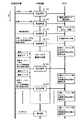
図2は本発明の第1の実施形態に係る中継装置の動作手順を示すシーケンス図である。矢印tの方向に時間が進行するものとする。 FIG. 2 is a sequence diagram showing an operation procedure of the relay device according to the first embodiment of the present invention. It is assumed that time advances in the direction of arrow t.
転送処理ユニット132は、外部診断機10が中継装置20のソフトウエアを書換えるとき、外部診断機10から送信されるECUに必要なデータをECU30、40、50、60へ転送をする。
The
まず外部診断機10から中継装置20へ、拡張セッション遷移コマンドが送られる(S110)。拡張セッション遷移コマンドは、中継装置のソフトウエアの書換え前のモード遷移をさせるコマンドである。転送処理ユニット132はECU30、40、50、60へ、拡張セッション遷移コマンドを送信する。ECU30、40、50、60はソフトウエアの書換え前のモードへ遷移する。
First, an extended session transition command is sent from the external
次に外部診断機10から中継装置20へ、故障コードセット停止コマンドが送られる(S120)。故障コードセット停止コマンドは、ECU30、40、50、60が故障を検出しても故障コードの記憶を行わないようにするコマンドである。また故障コードセット停止コマンドは、所定時間の間のみ有効であるコマンドである。
Next, a failure code set stop command is sent from the external
転送処理ユニット132は、ECU30、40、50、60へ、故障コードセットを行わないコマンドを送信する。ECU30、40、50、60は、このコマンドを受信すると、所定時間の間のみ、故障を検出しても故障コードの記憶を行わない。
The
次に外部診断機10から中継装置20へ、制御通信停止コマンドが送られる(S130)。制御通信停止コマンドは、CANバス2、3に接続された機器への制御に関する通信を禁止するコマンドである。また制御通信停止コマンドは、所定時間の間のみ有効であるコマンドである。
Next, a control communication stop command is sent from the external
転送処理ユニット132は、ECU30、40、50、60へ、制御通信停止コマンドを送信する。ECU30、40、50、60は、このコマンドを受信すると、所定時間のみ、CANバス2、3に接続された機器へ制御に関する全ての通信をしない。制御に関する通信とは、たとえば車速データの通信である。制御に関する通信データは、禁止されなければ全部のECU30、40、50、60へ周期的に送信される。
The
また転送処理ユニット132は、各ECU30、40、50、60からの制御に関する周期送信データの転送処理を禁止する。
In addition, the
次に外部診断機10から中継装置20へ、故障コードセット停止および制御通信停止状態の維持コマンドが送られる(S140)。故障コードセット停止および制御通信停止状態の維持コマンドは、故障コードセット停止を維持するためのコマンドと、制御通信停止を維持するためのコマンドである。また故障コードセット停止および制御通信停止状態の維持コマンドは、所定時間の間のみ有効であるコマンドである。
Next, a failure code set stop and control communication stop state maintenance command is sent from the external
転送処理ユニット132は、ECU30、40、50、60へ、故障コードセット停止および制御通信停止状態の維持コマンドを送信する。ECU30、40、50、60は、このコマンドを受信すると、所定時間の間のみ、故障を検出しても故障コードの記憶を行わず、CANバス2、3に接続された機器へ制御に関する全ての通信をしない状態を維持する。
The
次に外部診断機10から中継装置20へ、中継装置20のソフトウエアを書換えるデータが送られる。ソフト書換え処理ユニット134は、送られたデータに基づいて中継装置20のソフトウエアを書換える処理を実行する。この中継装置20のソフトウエアを書換えるデータは分散されて送信される。ソフト書換え処理ユニット134は、中継装置20のソフトウエアを書換える処理を次々と実行する。
Next, data for rewriting the software of the
中継装置20のソフトウエアを書換える処理の実行中に、外部診断機10から中継装置20へ、ステップS140で送られたコマンドと同じコマンドである、故障コードセット停止および制御通信停止状態の維持コマンドが送られる(S150)。転送処理ユニット132は、ECU30、40、50、60へ、故障コードセット停止および制御通信停止状態の維持コマンドを転送する。ECU30、40、50、60は、このコマンドを受信すると、所定時間の間のみ、引き続き故障を検出しても故障コードの記憶を行わず、CANバス2、3に接続された機器へ制御に関する全ての通信をしない。
During execution of the process of rewriting the software of the
中継装置20のソフトウエア書換えは短時間に行う必要があるので、中継装置20は、できるだけ他の処理を削減してソフトウエア書換えの処理に集中したい。ECU30、40、50、60に対して制御に関する送信を停止させることで、中継装置20がECU30、40、50、60からの制御に関するデータの受信、送信という通常実行している処理を省略することができる。
Since software rewriting of the
中継装置20のソフトウエア書換え中は、故障コードセット停止および制御通信停止状態の維持コマンドが、外部診断機10からを所定時間以内の周期で中継装置20へ送られる(S160)。その都度、転送処理ユニット132は、ECU30、40、50、60へ、故障コードセット停止および制御通信停止状態の維持コマンドを送信する。転送処理ユニット132は、故障コードセット停止および制御通信停止状態の維持コマンド以外はECU30、40、50、60へ転送しない。なお、所定時間がたとえば5secであれば、所定時間以内の周期は、たとえば2secとする。
While the software of the
すなわち転送処理ユニット132は、故障コードセット停止および制御通信停止状態の維持コマンドを転送することにより、各ECU30、40、50、60における、周期送信データの送信禁止及び周期送信データを受信しないことによる各ECU30、40、50、60内への故障コードの記憶禁止のうち少なくともいずれかを示す禁止データのCAN バス2、3への転送処理を許可する。
That is, the
また、転送処理ユニット132は、ECU30、40、50、60からの制御に関するデータの転送処理をステップS130の処理から禁止している。
In addition, the
そのため、ECU30、40、50、60同士で周期通信を行い、定期的に受信されるはずのデータが受信されないとエラーコードを記憶してしまう、という問題を防止することができる。このように各ECU30、40、50、60間における通信異常を発生させることなく、余計な負荷を中継装置20に与えずに中継装置20のソフトウエア書き換えを行うことができる。
Therefore, it is possible to prevent the problem that the periodic communication is performed between the
中継装置20のソフトウエア書換えが終了すると、外部診断機10から中継装置20へ故障コードセット停止および制御通信停止状態の維持コマンドは送信されない。そのため、転送処理ユニット132は、ECU30、40、50、60へ、故障コードセット停止および制御通信停止状態の維持コマンドを送信しない。
When the software rewriting of the
中継装置20のソフトウエア書換えが終了すると、ECU30、40、50、60は、故障コードセット停止および制御通信停止状態の維持コマンドを受信してから所定時間の間に次の故障コードセット停止および制御通信停止状態の維持コマンドを受信しないので、所定時間の経過後に故障コードセット停止および制御通信の送信停止状態を解除する。
When the software rewriting of the
これによりECU30、40、50、60は、ステップS110以前の動作状態に復帰する。すなわちECU30、40、50、60は、故障コードセット停止および制御通信停止状態の維持コマンドを示すデータを受信してから所定時間の経過後に、このデータを受信する以前の動作状態に復帰する。
Thereby, ECU30,40,50,60 returns to the operation state before step S110. That is,
外部診断機10は、中継装置20のソフトウエア書換えが終了すると、中継装置20へIG OFF/ONコマンドを送り、中継装置20を再起動させる。これにより外部診断機10による中継装置20のソフトウエア書換えが完了し、中継装置20は通常状態へ移行する。
When the software rewriting of the
なおECU30、40、50、60は、中継装置20のソフトウエア書換えが完了するか否かにかかわらず、故障コードセット停止コマンド、制御通信停止コマンド、故障コードセット停止および制御通信停止状態の維持コマンドを受信してから所定時間の間に次の故障コードセット停止および制御通信停止状態の維持コマンドを受信しなければ、ステップS110以前の動作状態に復帰する。
Note that the
これにより、外部診断機10と中継装置20とを接続するコネクタがソフトウエア書き換え途中で外れた場合等に、周期送信禁止の状態が解除されずに書き換えのやり直しが正常に行えなくなることを防止することができる。
As a result, when the connector that connects the external
本実施形態によれば、中継装置20の転送処理ユニット132は、外部診断機10によりソフトウエアが書き換えられている間は、CANバス2、3に接続された各ECU30、40、50、60からの制御通信データの転送処理を禁止し、外部診断機10から送信される、各ECU30、40、50、60における、周期送信データの送信禁止及び周期送信データを受信しないことによる各ECU30、40、50、60内への故障コードの記憶禁止のうち少なくともいずれかを示す禁止データのCANバス2、3への転送処理を許可する。
According to the present embodiment, the
なお、このような処理がされない場合は、次のような不都合も生じる。 In addition, when such a process is not performed, the following inconvenience occurs.
外部診断機10がECU30、40、50、60に対し直接通信できる環境では、故障コードストア停止信号と故障コードストア停止状態維持信号を、ECU30、40、50、60へ伝達することができるため、ECU30、40、50、60は故障を誤検知することはない。しかし、中継装置20が外部診断機10との間にある場合、外部診断機10が送信する信号を直接受信することができない。中継装置20のソフトウエア書換え中は、中継装置20がソフトウエア書換え専用のコマンドデータをECU30、40、50、60に送信することもできるが、それではECU30、40、50、60に、中継装置20のソフトウエア書換え専用のコマンドデータ処理を実装し、故障コードストア停止処理を実行する必要がある。
In an environment where the external
本実施形態ではソフトウエア書換え専用のコマンドデータ処理を不要とする。 In this embodiment, command data processing dedicated to software rewriting is not required.
また本実施形態によれば、中継装置20のソフトウエア書き換え中に、外部診断機10が各ECU30、40、50、60に送信する故障コードセット停止および制御通信停止状態の維持コマンドのデータを転送処理ユニット132が転送することにより、各ECU30、40、50、60間における通信異常を発生させることなく、余計な負荷を中継装置20に与えずに中継装置20のソフトウエア書き換えを行うことができる。
Further, according to the present embodiment, during the software rewriting of the
また本実施形態によれば、各ECU30、40、50、60における、周期送信データの送信禁止及び周期送信データを受信しないことによる各ECU30、40、50、60内への故障コードの記憶禁止のうち少なくともいずれかを示す禁止データは、各ECU30、40、50、60がこの禁止データを受信してから所定時間の間のみ有効であり、ECU30、40、50、60が禁止データを受信してから禁止データの有効期間である所定時間の経過後に、禁止データを受信する以前の動作状態に復帰する。中継装置20の転送処理ユニット132は、ソフトウエア書き換え中の間、外部診断機10からの禁止データを所定時間以内の周期で受信し、送信する。
Further, according to the present embodiment, the
これにより、外部診断機10をCANバス1に接続するコネクタがソフトウエア書き換え途中で外れた場合等に、周期送信禁止の状態が解除されずに書き換えのやり直しが正常に行えなくなることを防止することができる。
As a result, when the connector for connecting the external
≪第2実施形態≫
次に、本発明の第2の実施形態に係る中継装置について説明する。
<< Second Embodiment >>
Next, a relay device according to the second embodiment of the present invention will be described.
図3は本発明の第2の実施形態に係る中継装置を含む車載ネットワークの構成を示す図である。なお、図1に示す第1の実施形態に係る中継装置と同じ構成要素については、図1と同じ符号を用いるものとする。また、図1と同じ符号を用いた構成要素については、上述した図1についての説明を援用するものとする。 FIG. 3 is a diagram showing a configuration of an in-vehicle network including a relay device according to the second embodiment of the present invention. In addition, the same code | symbol as FIG. 1 shall be used about the same component as the relay apparatus which concerns on 1st Embodiment shown in FIG. Moreover, the description about FIG. 1 mentioned above shall be used about the component using the same code | symbol as FIG.
第2の実施形態に係る中継装置220では、中継装置220自身のソフトウエアを書換え中、外部診断機210からECU30、40、50、60へのコマンドが中継装置220へ送られない。その代わりに中継装置220が定期的にECU30、40、50、60へ必要なコマンドを送る。
In the
外部診断機210と中継装置220との接続、中継装置220とECU30、40、50、60との接続は第1の実施形態と同様である。
The connection between the external
外部診断機210はECU30、40、50、60へのコマンドを中継装置220へ送信しない点が第1の実施形態の外部診断機10と異なる。
The external
中継装置220は、記憶ユニット240を備える。
The
記憶ユニット240は、半導体メモリやハードディスク装置(HDD、Hard Disc Driver)を含む、任意の不揮発性の記憶装置又は不揮発性の記憶装置と揮発性の記憶装置との組み合わせとすることができる。記憶ユニット240は、予め定義されたコマンドセットとして拡張セッション遷移コマンドと、故障コードセット停止コマンドと、制御通信停止コマンドと、故障コードセット停止および制御通信停止状態の維持コマンドとを、記憶する。
The
また中継装置220は、転送処理ユニット132の代わりに送信処理ユニット232を備える。
The
これらに伴い、中継装置220は、処理ユニット130の代わりに処理ユニット230を備える。
Accordingly, the
次に、送信処理ユニット232が実行する送信処理の動作を説明する。
Next, the operation of transmission processing executed by the
図4は、第2の実施形態に係る中継装置220の動作手順を示すシーケンス図である。
FIG. 4 is a sequence diagram illustrating an operation procedure of the
外部診断機210からソフト書換えデータが送られると、ソフト書換え処理ユニット134は、送られてくるデータに基づいて中継装置220自身のソフトウエアを書換える処理を実行する。
When the software rewrite data is sent from the external
また、ソフトウエア書換えデータが送られると、送信処理ユニット232は、記憶ユニット240に記憶した拡張セッション遷移コマンド、故障コードセット停止コマンド、制御通信停止コマンドを連続してECU30、40、50、60へ送信する(S210、S220、S230)。
When the software rewrite data is sent, the
ソフト書換え中、送信処理ユニット232は、記憶ユニット240に記憶した故障コードセット停止および制御通信停止状態の維持コマンドを、所定時間以内の周期で定期的にECU30、40、50、60へ送信する(S240、S250)。
During the software rewriting, the
これによりECU30、40、50、60は、故障を検出しても故障コードの記憶を行わず、所定時間の間のみ、CANバス2、3に接続された機器へ制御に関する全ての通信をしないことを継続する。
As a result, the
またソフト書換え中、処理ユニット230は、ECU30、40、50、60からの制御に関するデータの転送処理を禁止する。
During software rewriting, the
このようにECU30、40、50、60は、第1の実施形態と同様に、ECU30、40、50、60同士で周期通信を行い、定期的に受信されるはずのデータが受信されないとエラーコードを記憶してしまう、という問題を防止することができる。また、各ECU30、40、50、60間における通信異常を発生させることなく、余計な負荷を中継装置20に与えずに中継装置20のソフトウエア書き換えを行うことができる。
As described above, the
中継装置220のソフトウエア書換えが終了した後の処理は、第1の実施形態と同じである。
The processing after the software rewriting of the
なおソフトウエア書換えデータが送られる前は、第1の実施形態のように外部診断機210からECU30、40、50、60への制御コマンドが送られ、その制御コマンドをECU30、40、50、60へ転送する形態であってもよい。その場合、送信処理ユニット232は、ソフトウエア書換え中に故障コードセット停止および制御通信停止状態の維持コマンドをECU30、40、50、60へ定期的に送信する処理だけを実行する。
Before the software rewrite data is sent, a control command is sent from the external
本実施形態では、中継装置220のソフトウエア書換え中に外部診断機210からECU30、40、50、60へのコマンドが送られない代わりに、中継装置220が自発的に記憶ユニット240に記憶した故障コードセット停止および制御通信停止状態の維持コマンドを、その有効時間である所定時間以内の時間間隔でECU30、40、50、60へ送る。
In the present embodiment, a failure that the
本実施形態によれば、中継装置220が書き換えられている間は、送信処理ユニット232は、CAN バス2、3に接続された各ECU30、40、50、60における、周期送信データの送信禁止及び周期送信データを受信しないことによる各ECU30、40、50、60内への故障コードの記憶禁止のうち少なくともいずれかを示す禁止データをCAN バス2、3に送信する。
According to the present embodiment, while the
これにより、中継装置220のソフトウエア書き換え中はECU30、40、50、60間の通信を禁止させ、故障コードの記憶を禁止させる禁止データをCANバス2、3に送信することで、各ECU30、40、50、60間における通信異常を発生させることなく、余計な負荷を中継装置220に与えずに中継装置220のソフトウエア書き換えを行うことができる。
Thereby, during software rewriting of the
また、外部診断機210から故障コードセット停止コマンドや制御通信停止コマンドなどが受信できない場合であっても、中継装置220は自身が書換え中であることを検知してそれらの信号を自発的に送信することができるため、通信タフネスが向上する。
Even when a failure code set stop command, control communication stop command, or the like cannot be received from the external
また本実施形態によれば、各ECU30、40、50、60における、周期送信データの送信禁止及び周期送信データを受信しないことによる各ECU30、40、50、60内への故障コードの記憶禁止のうち少なくともいずれかを示す禁止データは、各ECU30、40、50、60がこの禁止データを受信してから所定時間の間のみ有効であり、ECU30、40、50、60が禁止データを受信してから禁止データの有効期間である所定時間の経過後に、禁止データを受信する以前の動作状態に復帰する。中継装置220の送信処理ユニット232は、ソフトウエア書き換え中の間、禁止データを所定時間以内の周期で送信する。
Further, according to the present embodiment, the
これにより、外部診断機210をCANバス1に接続するコネクタがソフトウエア書き換え途中で外れた場合等に、周期送信禁止の状態が解除されずに書き換えのやり直しが正常に行えなくなることを防止することができる。
As a result, when the connector that connects the external
また本実施形態によれば、中継装置220自身のソフトウエア書換えを示す信号を新たに定義し送信する必要が無い。これにより、外部診断機210から直接信号を受信できないECU30、40、50、60に、中継装置220のソフトウエア書換え時の故障コードストア停止およびその状態維持に関わる処理を追加する必要が無い。
なお本発明の実施の形態は、上述した実施の形態に限定されるものではなく、本技術の要旨を逸脱しない範囲において種々の変更が可能である。
Further, according to this embodiment, there is no need to newly define and transmit a signal indicating software rewriting of the
The embodiments of the present invention are not limited to the above-described embodiments, and various modifications can be made without departing from the gist of the present technology.
10、210・・・外部診断機、20、220・・・中継装置、30、40、50、60・・・ECU、110・・・受信IF、120・・・送信IF、130、230・・・処理ユニット、132・・・転送処理ユニット、134・・・ソフト書換え処理ユニット、232・・・送信処理ユニット、240・・・記憶ユニット。 10, 210 ... External diagnostic machine, 20, 220 ... Relay device, 30, 40, 50, 60 ... ECU, 110 ... Reception IF, 120 ... Transmission IF, 130, 230 ... Processing unit 132: Transfer processing unit 134: Software rewrite processing unit 232: Transmission processing unit 240: Storage unit
Claims (4)
前記処理ユニットは、
外部装置により前記中継装置のソフトウエアが書き換えられている間は、前記ネットワークバスに接続された各電子制御装置からのデータの転送処理を禁止し、
前記外部装置から送信される、前記各電子制御装置における、周期送信データの送信禁止及び前記周期送信データを受信しないことによる前記各電子制御装置内への故障コードの記憶禁止のうち少なくともいずれかを示す禁止データの前記ネットワークバスへの転送処理を許可し、
前記禁止データは、前記各電子制御装置が前記禁止データを受信してから所定時間の間のみ有効であり、
前記各電子制御装置は、前記禁止データを受信してから前記禁止データの有効期間である前記所定時間の経過後に、前記禁止データを受信する以前の動作状態に復帰し、
前記処理ユニットは、前記書き換え中、前記外部装置からの前記禁止データを前記所定時間以内の周期で受信する、
中継装置。 A relay device comprising a processing unit and interposed in a network bus to which a plurality of electronic control devices are communicably connected,
The processing unit is
While the software of the relay device is being rewritten by an external device, data transfer processing from each electronic control device connected to the network bus is prohibited,
At least one of transmission prohibition of periodic transmission data transmitted from the external device and storage of a fault code in each electronic control device by not receiving the periodic transmission data in each electronic control device Allow transfer processing of the prohibited data to the network bus ,
The prohibited data is valid only for a predetermined time after each electronic control device receives the prohibited data,
Each of the electronic control devices returns to the operation state before receiving the prohibition data after the lapse of the predetermined time, which is a valid period of the prohibition data after receiving the prohibition data,
The processing unit receives the prohibition data from the external device in the cycle within the predetermined time during the rewriting,
Relay device.
請求項1に記載の中継装置。 The prohibition data is at least one of maintaining prohibition of transmission of periodic transmission data in each electronic control device and maintaining prohibition of storing fault codes in each electronic control device by not receiving the periodic transmission data. Is a maintenance command indicating either
The relay device according to claim 1.
前記処理ユニットは、前記中継装置のソフトウエアが書き換えられている間は、前記ネットワークバスに接続された各電子制御装置における、周期送信データの送信禁止及び前記周期送信データを受信しないことによる前記各電子制御装置内への故障コードの記憶禁止のうち少なくともいずれかを示す禁止データを前記ネットワークバスに送信し、
前記禁止データは、前記各電子制御装置が前記禁止データを受信してから所定時間の間のみ有効であり、
前記各電子制御装置は、前記禁止データを受信してから前記禁止データの有効期間である前記所定時間の経過後に、前記禁止データを受信する以前の動作状態に復帰し、
前記処理ユニットは、前記書き換え中、前記禁止データを前記所定時間以内の周期で前記ネットワークバスに送信する、
中継装置。 A relay device comprising a processing unit and interposed in a network bus to which a plurality of electronic control devices are communicably connected,
The processing unit is configured to prohibit transmission of periodic transmission data and not to receive the periodic transmission data in each electronic control device connected to the network bus while the software of the relay device is being rewritten. Sending prohibition data indicating at least one of the prohibition of storing fault codes in the electronic control unit to the network bus ;
The prohibited data is valid only for a predetermined time after each electronic control device receives the prohibited data,
Each of the electronic control devices returns to the operation state before receiving the prohibition data after the lapse of the predetermined time, which is a valid period of the prohibition data after receiving the prohibition data,
The processing unit transmits the prohibition data to the network bus at a cycle within the predetermined time during the rewriting.
Relay device.
請求項3に記載の中継装置。 The prohibition data is at least one of maintaining prohibition of transmission of periodic transmission data in each electronic control device and maintaining prohibition of storing fault codes in each electronic control device by not receiving the periodic transmission data. Is a maintenance command indicating either
The relay device according to claim 3.
Priority Applications (3)
| Application Number | Priority Date | Filing Date | Title |
|---|---|---|---|
| JP2013108940A JP5702829B2 (en) | 2013-05-23 | 2013-05-23 | Relay device |
| US14/279,367 US9081699B2 (en) | 2013-05-23 | 2014-05-16 | Relay device |
| DE102014209752.5A DE102014209752B4 (en) | 2013-05-23 | 2014-05-22 | relay means |
Applications Claiming Priority (1)
| Application Number | Priority Date | Filing Date | Title |
|---|---|---|---|
| JP2013108940A JP5702829B2 (en) | 2013-05-23 | 2013-05-23 | Relay device |
Publications (2)
| Publication Number | Publication Date |
|---|---|
| JP2014230140A JP2014230140A (en) | 2014-12-08 |
| JP5702829B2 true JP5702829B2 (en) | 2015-04-15 |
Family
ID=51863393
Family Applications (1)
| Application Number | Title | Priority Date | Filing Date |
|---|---|---|---|
| JP2013108940A Active JP5702829B2 (en) | 2013-05-23 | 2013-05-23 | Relay device |
Country Status (3)
| Country | Link |
|---|---|
| US (1) | US9081699B2 (en) |
| JP (1) | JP5702829B2 (en) |
| DE (1) | DE102014209752B4 (en) |
Families Citing this family (15)
| Publication number | Priority date | Publication date | Assignee | Title |
|---|---|---|---|---|
| JP6024564B2 (en) * | 2013-03-28 | 2016-11-16 | 株式会社オートネットワーク技術研究所 | In-vehicle communication system |
| JP2016107908A (en) * | 2014-12-09 | 2016-06-20 | 株式会社デンソー | On-vehicle network system |
| US10091703B2 (en) | 2015-03-20 | 2018-10-02 | Denso Corporation | Relay apparatus |
| JP6471613B2 (en) * | 2015-05-28 | 2019-02-20 | 株式会社オートネットワーク技術研究所 | Relay device and communication system |
| US10287909B2 (en) * | 2015-05-29 | 2019-05-14 | Pratt & Whitney Canada Corp. | Method and kit for preserving a fuel system of an aircraft engine |
| JP6281535B2 (en) | 2015-07-23 | 2018-02-21 | 株式会社デンソー | Relay device, ECU, and in-vehicle system |
| JP6489050B2 (en) | 2016-03-24 | 2019-03-27 | 株式会社オートネットワーク技術研究所 | Information processing apparatus and information processing system |
| DE102016208937A1 (en) * | 2016-05-24 | 2017-11-30 | Robert Bosch Gmbh | Motor vehicle interface Interface |
| US10259469B2 (en) * | 2016-06-08 | 2019-04-16 | Ford Global Technologies, Llc | Methods and apparatus to selectively disable functions of electronic control units |
| JP6620133B2 (en) * | 2017-09-28 | 2019-12-11 | 株式会社Subaru | Vehicle communication control device and vehicle communication control system |
| JP6913621B2 (en) * | 2017-12-19 | 2021-08-04 | 日立Astemo株式会社 | Electronic control device for automobiles |
| FR3077904A1 (en) * | 2018-02-09 | 2019-08-16 | Continental Automotive France | METHOD FOR CONTROLLING AN ELECTRONIC CONTROL UNIT COMPRISING AT LEAST TWO HEADS OF EXECUTION |
| US10972401B1 (en) * | 2018-10-16 | 2021-04-06 | Brunswick Corporation | Marine propulsion control system and method with configuration functionality via CAN bus |
| CN113765608B (en) * | 2020-06-04 | 2022-11-25 | 华为技术有限公司 | Fault diagnosis method, electronic device, and storage medium |
| CN112153578B (en) * | 2020-11-30 | 2021-03-02 | 广州汽车集团股份有限公司 | Vehicle configuration code self-checking method and vehicle |
Family Cites Families (31)
| Publication number | Priority date | Publication date | Assignee | Title |
|---|---|---|---|---|
| US5278759A (en) | 1991-05-07 | 1994-01-11 | Chrysler Corporation | System and method for reprogramming vehicle computers |
| JP2812189B2 (en) * | 1994-02-10 | 1998-10-22 | 日本電気株式会社 | How to download the program |
| US6275911B1 (en) * | 1996-09-20 | 2001-08-14 | Denso Corporation | Memory writing device for an electronic device |
| US6144887A (en) * | 1996-12-09 | 2000-11-07 | Denso Corporation | Electronic control unit with reset blocking during loading |
| JP3314749B2 (en) * | 1999-02-17 | 2002-08-12 | 株式会社デンソー | Electronic control unit |
| US6850973B1 (en) | 1999-09-29 | 2005-02-01 | Fisher-Rosemount Systems, Inc. | Downloadable code in a distributed process control system |
| DE10014561A1 (en) | 2000-03-23 | 2001-09-27 | Mannesmann Vdo Ag | Method for re-programming a control device, especially for motor vehicle use, where a command for updating of data or code in memory is received from an external device during system initialization preventing system loading |
| JP2003140737A (en) * | 2001-10-30 | 2003-05-16 | Fujitsu Ten Ltd | Support system |
| JP2003244187A (en) * | 2002-02-19 | 2003-08-29 | Denso Corp | On-vehicle gateway device and computer program |
| JP2007507016A (en) * | 2003-06-24 | 2007-03-22 | ローベルト ボッシュ ゲゼルシャフト ミット ベシュレンクテル ハフツング | Software update method for electronic control device by flash programming via serial interface and state automatic device corresponding thereto |
| US8856370B2 (en) * | 2004-11-05 | 2014-10-07 | International Business Machines Corporation | Concurrent flashing of data processing units in hierarchical networks |
| KR20060054980A (en) * | 2004-11-17 | 2006-05-23 | 삼성전자주식회사 | Method of upgrading software of apparatus including a plurality of microprocessors, and apparatus therefor |
| US7562167B2 (en) * | 2005-11-14 | 2009-07-14 | Deere & Company | Managing heterogeneous data streams for remote access |
| JP4361540B2 (en) | 2006-03-06 | 2009-11-11 | 富士通テン株式会社 | Gateway device, data transfer method, and program |
| JP5095130B2 (en) * | 2006-05-26 | 2012-12-12 | 株式会社オートネットワーク技術研究所 | Relay connection unit |
| JP2008155736A (en) * | 2006-12-22 | 2008-07-10 | Fujitsu Ten Ltd | Electronic control device |
| JP4492618B2 (en) * | 2007-01-18 | 2010-06-30 | トヨタ自動車株式会社 | Vehicle control system |
| JP4367513B2 (en) * | 2007-03-28 | 2009-11-18 | 株式会社デンソー | Electronic control unit |
| JP2008312024A (en) * | 2007-06-15 | 2008-12-25 | Auto Network Gijutsu Kenkyusho:Kk | Transit connection unit |
| US20090119657A1 (en) * | 2007-10-24 | 2009-05-07 | Link Ii Charles M | Methods and systems for software upgrades |
| US8239850B2 (en) * | 2007-12-14 | 2012-08-07 | GM Global Technology Operations LLC | Computer-implemented method of releasing battery state estimation software |
| JP4478731B2 (en) * | 2008-02-20 | 2010-06-09 | 富士通テン株式会社 | Communication device and gateway device |
| JP5007315B2 (en) * | 2009-04-03 | 2012-08-22 | 本田技研工業株式会社 | In-vehicle gateway device |
| JP2010258990A (en) * | 2009-04-28 | 2010-11-11 | Autonetworks Technologies Ltd | Control system and control program updating method |
| JP5255579B2 (en) * | 2010-02-09 | 2013-08-07 | 日立オートモティブシステムズ株式会社 | In-car data relay device, vehicle control system |
| CN202362661U (en) * | 2011-11-30 | 2012-08-01 | 江苏欣盛自控科技有限公司 | CAN bus communication-based direct digital controller |
| US20140006555A1 (en) * | 2012-06-28 | 2014-01-02 | Arynga Inc. | Remote transfer of electronic images to a vehicle |
| KR20140038160A (en) * | 2012-09-20 | 2014-03-28 | 한국전자통신연구원 | Method for updating ecu in system based on autosar and apparatus for the same |
| KR20140061128A (en) * | 2012-11-13 | 2014-05-21 | 한국전자통신연구원 | Electronic control unit based on automobile open system architecture and method for updating the ecu |
| CN103117920A (en) * | 2013-02-01 | 2013-05-22 | 奇瑞汽车股份有限公司 | Vehicular independent gateway |
| JP6024564B2 (en) * | 2013-03-28 | 2016-11-16 | 株式会社オートネットワーク技術研究所 | In-vehicle communication system |
-
2013
- 2013-05-23 JP JP2013108940A patent/JP5702829B2/en active Active
-
2014
- 2014-05-16 US US14/279,367 patent/US9081699B2/en active Active
- 2014-05-22 DE DE102014209752.5A patent/DE102014209752B4/en active Active
Also Published As
| Publication number | Publication date |
|---|---|
| US20140351460A1 (en) | 2014-11-27 |
| JP2014230140A (en) | 2014-12-08 |
| DE102014209752B4 (en) | 2015-10-29 |
| US9081699B2 (en) | 2015-07-14 |
| DE102014209752A1 (en) | 2014-11-27 |
Similar Documents
| Publication | Publication Date | Title |
|---|---|---|
| JP5702829B2 (en) | Relay device | |
| US10778696B2 (en) | Vehicle-mounted relay device for detecting an unauthorized message on a vehicle communication bus | |
| JP6585019B2 (en) | Network monitoring device, network system and program | |
| US9947144B2 (en) | Error variance detection method of CAN communication system and the CAN communication system | |
| US10591884B2 (en) | Controller and control program updating method | |
| WO2017038422A1 (en) | Communication device | |
| JP6369341B2 (en) | In-vehicle communication system | |
| US10384625B2 (en) | Communication device and non-transitory recording medium | |
| JP2006191338A (en) | Gateway apparatus for diagnosing fault of device in bus | |
| US10296322B2 (en) | Controller and control program updating method | |
| JP6620133B2 (en) | Vehicle communication control device and vehicle communication control system | |
| KR102002517B1 (en) | Method and system for configuration of ecu security | |
| US20180316721A1 (en) | Information processing device, information processing system, information processing method, and information processing program | |
| US20170187567A1 (en) | Electronic control apparatus | |
| US20200177412A1 (en) | Monitoring device, monitoring system, and computer readable storage medium | |
| JP6345447B2 (en) | Electronic control unit for automobile | |
| US10917387B2 (en) | Information processing device, information processing system, information processing method, and information processing program | |
| JP6455220B2 (en) | Communications system | |
| JP7006461B2 (en) | Electronic control device and electronic control system | |
| US11012453B2 (en) | Method for protecting a vehicle network against manipulated data transmission | |
| JP2020022019A (en) | Vehicle system | |
| JP7411467B2 (en) | Electronic control device and program rewriting control method | |
| CN115668872A (en) | In-vehicle device, in-vehicle communication system, and communication control method | |
| JP2010258635A (en) | Control apparatus | |
| US20200406842A1 (en) | Vehicle Control Apparatus and Method for Rewriting Program Therefor |
Legal Events
| Date | Code | Title | Description |
|---|---|---|---|
| A131 | Notification of reasons for refusal |
Free format text: JAPANESE INTERMEDIATE CODE: A131 Effective date: 20141204 |
|
| A521 | Written amendment |
Free format text: JAPANESE INTERMEDIATE CODE: A523 Effective date: 20150119 |
|
| TRDD | Decision of grant or rejection written | ||
| A01 | Written decision to grant a patent or to grant a registration (utility model) |
Free format text: JAPANESE INTERMEDIATE CODE: A01 Effective date: 20150210 |
|
| A61 | First payment of annual fees (during grant procedure) |
Free format text: JAPANESE INTERMEDIATE CODE: A61 Effective date: 20150220 |
|
| R150 | Certificate of patent or registration of utility model |
Ref document number: 5702829 Country of ref document: JP Free format text: JAPANESE INTERMEDIATE CODE: R150 |