JP2020022019A - Vehicle system - Google Patents
Vehicle system Download PDFInfo
- Publication number
- JP2020022019A JP2020022019A JP2018143091A JP2018143091A JP2020022019A JP 2020022019 A JP2020022019 A JP 2020022019A JP 2018143091 A JP2018143091 A JP 2018143091A JP 2018143091 A JP2018143091 A JP 2018143091A JP 2020022019 A JP2020022019 A JP 2020022019A
- Authority
- JP
- Japan
- Prior art keywords
- vehicle
- transmission
- electronic control
- failure diagnosis
- response
- Prior art date
- Legal status (The legal status is an assumption and is not a legal conclusion. Google has not performed a legal analysis and makes no representation as to the accuracy of the status listed.)
- Pending
Links
Images


Abstract
Description
本発明は、車両システムに関する。 The present invention relates to a vehicle system.
本技術分野の背景技術として、特開2003−256033号公報(特許文献1)がある。特許文献1の要約欄には、「車両内に配線された車両内LANのバス10には多数のECU、すなわちECU1,ECU2,ECU3,・・・が接続されており、各ECU間は相互に通信可能となっている。ECU1には故障診断ツール20が接続され、ECU1は故障診断ツール20より要求メッセージを受信し当該要求メッセージをECU2等に送信すると共にECU2等からの応答を故障診断ツール20に返信する。ECU1は、故障診断ツール20から要求されると事前に分かっている項目について故障診断ツール20からの要求に関係なく要求メッセージをECU2等に送信し、その応答の結果を保存する。」と記載されている。
As a background art of this technical field, there is Japanese Patent Application Laid-Open No. 2003-256033 (Patent Document 1). The summary column of
故障診断ツールからの要求メッセージには一度の要求メッセージに対し、一定の周期で故障診断情報を応答する場合、複数の車載用ECUから故障診断ツールへ一斉に応答を送信する。そのため、ネットワークに定期的に送信される車両制御用のデータを含め、大量のデータが送信されネットワークが高負荷となり、車載用ECUからの応答に遅れが生じる。さらに、一定の周期での応答が出来なく、故障診断情報に欠けが生じる可能性がある。 In the case of responding to a single request message with failure diagnosis information at a fixed cycle in response to a request message from the failure diagnosis tool, a plurality of in-vehicle ECUs simultaneously transmit responses to the failure diagnosis tool. Therefore, a large amount of data is transmitted including the vehicle control data that is periodically transmitted to the network, and the network is overloaded, resulting in a delay in the response from the vehicle-mounted ECU. Furthermore, there is a possibility that a response cannot be made at a constant cycle, and the failure diagnosis information may be missing.
そこで、本発明は、上記課題に鑑みてなされたものであり、車載用ECUから故障診断ツールへ送信される応答メッセージが増加し、ネットワークが高負荷となった場合でも、CAN上で通信されるデータ量を減らし、車載用ECUから応答可能とするものである。 In view of the above, the present invention has been made in view of the above problems, and the number of response messages transmitted from the in-vehicle ECU to the failure diagnosis tool increases, and communication is performed on the CAN even when the network becomes heavily loaded. This reduces the amount of data and makes it possible to respond from the in-vehicle ECU.
例えば、上記課題を解決するために、車両を制御する複数の電子制御装置と、複数の前記電子制御装置が接続される車載ネットワークと、前記車載ネットワークを介して前記電子制御装置から周期的に制御用データを送信する送信部と、前記車両の故障診断を行う診断部と、周期的な送信要求を受信した前記電子制御装置の前記故障診断の結果を周期的に応答する応答部と、前記故障診断の結果の前記応答時に前記車載ネットワークの負荷が高い場合、前記他の電子制御装置に対する送信の抑制命令をする命令部と、前記抑制命令を送信した前記電子制御装置、及び前記抑制命令を受信した前記他の電子制御装置は、制御用データを送信する周期を長くする。 For example, in order to solve the above-mentioned problems, a plurality of electronic control devices for controlling a vehicle, a vehicle-mounted network to which the plurality of electronic control devices are connected, and periodic control from the electronic control device via the vehicle-mounted network A transmission unit for transmitting data for use, a diagnosis unit for performing a failure diagnosis of the vehicle, a response unit for periodically responding to a result of the failure diagnosis of the electronic control device that has received a periodic transmission request, When the load on the on-vehicle network is high at the time of the response as a result of the diagnosis, a command unit that performs a command to suppress transmission to the other electronic control device, the electronic control device that transmitted the suppression command, and the reception of the suppression command The other electronic control device described above lengthens the period for transmitting control data.
本発明によれば、CAN上で通信されるデータ量を減らし、ネットワークの負荷を低下させ、車載用ECUからの応答を可能とする。本発明に関連する更なる特徴は、本明細書の記述、添付図面から明らかになるものである。また、上記した以外の、課題、構成及び効果は、以下の実施例の説明により明らかにされる。 ADVANTAGE OF THE INVENTION According to this invention, the amount of data communicated on CAN is reduced, the load of a network is reduced, and a response from an in-vehicle ECU is enabled. Further features related to the present invention will become apparent from the description of the present specification and the accompanying drawings. Problems, configurations, and effects other than those described above will be clarified by the following description of the embodiments.
以下、添付図面を参照して本発明の実施例について説明する。添付図面は本発明の原理に則った具体的な実施例を示しているが、これらは本発明の理解のためのものであり、本発明を限定的に解釈するために用いられるものではない。 Hereinafter, embodiments of the present invention will be described with reference to the accompanying drawings. The accompanying drawings show specific embodiments in accordance with the principles of the present invention, but these are for understanding the present invention, and are not used to limit the present invention.
車両には車載用ECU(Electronic Control Unit、電子制御装置)が複数搭載され、それぞれがCAN(Controller Area Network)等の車載ネットワークにより接続される。車両診断の際には故障診断ツール(診断部)が車載ネットワークに接続され、故障診断ツールと各車載用ECUとダイアログ通信を行う事により、各車載用ECUが自己診断した故障情報などを故障診断ツールに送信する。 The vehicle is equipped with a plurality of in-vehicle ECUs (Electronic Control Units, electronic control units), each of which is connected by an in-vehicle network such as a CAN (Controller Area Network). At the time of vehicle diagnosis, a failure diagnosis tool (diagnosis unit) is connected to the in-vehicle network and performs dialog communication with the failure diagnosis tool and each in-vehicle ECU, thereby performing failure diagnosis of failure information etc. self-diagnosed by each in-vehicle ECU. Submit to the tool.
故障診断ツールは各車載用ECUに対し、故障診断に必要なデータを要求するメッセージを送信する。各車載用ECUは要求メッセージを故障診断ツールより受信したら、要求メッセージにて要求された故障診断情報を故障診断ツールに対し応答する。 The failure diagnosis tool transmits a message requesting data necessary for failure diagnosis to each vehicle-mounted ECU. Upon receiving the request message from the failure diagnosis tool, each in-vehicle ECU responds to the failure diagnosis tool with the requested failure diagnosis information in the request message.
車載用ECUは協調動作する為、CAN等の車載ネットワークは診断だけでなく、車両制御に必要な車速やエンジン回転数などの情報を通信する為にも使用される。車両制御に必要な情報の通信は、任意周期での送信で行われる。 Since the in-vehicle ECUs cooperate, the in-vehicle network such as CAN is used not only for diagnosis but also for communicating information such as vehicle speed and engine speed required for vehicle control. Communication of information necessary for vehicle control is performed by transmission at an arbitrary cycle.
CANネットワークによる通信では、ISO(International Organization for Standardization)11898−1の規定により、データ内容や送信ノードを識別するためにID(識別子)が使用され、通信調停の優先順位を決定する働きをする。通信調停の優先順位は、IDの値が小さい方が高くなるよう規定されている。 In communication by the CAN network, an ID (identifier) is used to identify data contents and a transmission node according to ISO (International Organization for Standardization) 11898-1, and serves to determine the priority of communication arbitration. The priority of communication arbitration is defined such that the smaller the value of the ID, the higher the priority.
例えば、複数の車載用ECUより同時に送信が行われた場合、小さいIDが優先的に送信され、送信が完了次第、大きいIDが送信される。 For example, when transmission is performed simultaneously from a plurality of vehicle-mounted ECUs, a small ID is transmitted with priority, and a large ID is transmitted as soon as transmission is completed.
以下の実施例は、車両の動作を制御する際に利用される、車載ネットワークにおいて通信されるデータ量を減らし、車載用ECUから応答する時間を確保することを可能とする技術に関する。 The following embodiment relates to a technology that is used when controlling the operation of a vehicle and that reduces the amount of data communicated in an in-vehicle network and can secure a response time from an in-vehicle ECU.
以下の実施例は、故障診断ツールからの要求メッセージが送信された時にネットワークが高負荷の状態となり、車載用ECUが応答出来なくなった場合、車載用ECUは他の車載用ECUが送信しているIDよりも優先順位の高い任意のIDにて他の車載用ECUに対しCAN送信を抑制するメッセージを送信する。他の車載用ECUはメッセージを受信後、車両制御に使用しているデータの内、送信周期を伸ばしても影響の出ない情報の周期を伸ばす事により、ネットワークの負荷を低下させる技術とを備える車載用制御装置が可能となる。 In the following embodiment, when the request message from the failure diagnosis tool is transmitted, the network is in a high load state, and if the in-vehicle ECU cannot respond, the in-vehicle ECU is transmitting from another in-vehicle ECU. A message for suppressing CAN transmission is transmitted to another in-vehicle ECU with an arbitrary ID having a higher priority than the ID. Other in-vehicle ECUs have a technology that reduces the load on the network by extending the period of information that is not affected even if the transmission period is extended among the data used for vehicle control after receiving the message. An in-vehicle control device becomes possible.
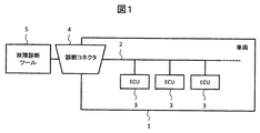
図1は、車載ネットワークシステムの構成を示すブロック図である。車載ネットワークシステムは、車両1に搭載されたバス2、バス2により接続された車両を制御する為のECU5、車両1の車両ネットワークと故障診断ツール5を接続する接続する為の診断コネクタ4を含むように構成されている。
FIG. 1 is a block diagram showing a configuration of the vehicle-mounted network system. The in-vehicle network system includes a
また、車載ネットワーク(バス2)を介して電子制御装置3から周期的に制御用データを送信する送信部(図示しない)、周期的な送信要求を受信した電子制御装置3の故障診断の結果を周期的に応答する応答部(図示しない)、故障診断の結果の応答時に車載ネットワークの負荷が高い場合、他の電子制御装置3に対する送信の抑制命令をする命令部(図示しない)を有する。
Further, a transmission unit (not shown) for periodically transmitting control data from the
ECU3は、内部にCPU、ROM、RAM、CANコントローラを備えている。ROMは、CPUが実行する制御プログラムを格納する記憶装置である。RAMは、例えば、CPUが制御プログラムを実行している間に用いる変数などのデータを格納する記憶装置である。CANコントローラはバス2に対し、データの送受信を行う装置である。
The
図1では説明の為、ECU3と接続するバス(車載ネットワーク)2は1本となっているが、一般的には、CANネットワークやLIN(Local Interconnect Network)など複数のネットワークがゲートウェイにより接続されている。 In FIG. 1, the bus (vehicle-mounted network) 2 connected to the ECU 3 is one for the sake of explanation. However, in general, a plurality of networks such as a CAN network and a LIN (Local Interconnect Network) are connected by a gateway. I have.
図2は、車載ネットワーク上のCANネットワークの通信を示す模式図である。図の縦軸にCANネットワーク上で送受信されるデータの項目及びCAN通信負荷102を示し、横軸に時間軸を示す。CANネットワーク上で送受信されるデータの項目として、故障診断ツール101からの送信データ及び、各ECUからの診断に関するデータの送信を示すECU1 130、ECU2 131、ECU3 132がある。また、ネットワーク負荷102は各ECUから車両制御に必要な車速やエンジン回転数などのデータ送信によるネットワーク負荷を示す。
FIG. 2 is a schematic diagram showing communication of a CAN network on a vehicle-mounted network. The vertical axis of the figure shows the items of data transmitted and received on the CAN network and the
図2では説明の為、ネットワーク負荷102に示すネットワーク負荷は一時的な高負荷状態が断続的に発生する表現としているが、実際には各ECUが送信する車両制御などに必要なデータは複数のIDにより行われている事に加え、ID毎に送信周期が異なる為、実際は不均一なネットワーク負荷となる。
In FIG. 2, for the sake of explanation, the network load indicated by the
CAN通信の特長の一つとして、データ内容や送信ノードを識別するためにID(識別子)が使用され、通信調停の優先順位の決定が行われる。図2で示すCANネットワークでは以下の優先順位となるIDとして説明する。 As one of the features of the CAN communication, an ID (identifier) is used to identify data contents and a transmission node, and the priority of communication arbitration is determined. In the CAN network shown in FIG. 2, description will be made as IDs having the following priorities.
ECU2 131の要求191<ネットワーク負荷102で送信されているID群<故障診断ツール101の要求<ECU1 130の応答<ECU2 131の応答<ECU3 132の応答。
故障診断ツール101より、各ECUに向けて送信されるECU1要求151及び、ECU2要求152、ECU3要求153はそれぞれ順に、ECU1 130、ECU2 131、ECU3 132に対して、故障診断結果の周期応答を要求する送信データである。
The ECU1 request 151, the ECU2 request 152, and the
故障診断ツール101は、ECU1 130に対し任意のタイミングで、ECU1要求151を送信する。この時、ECU1要求151はネットワーク負荷102で送信されているID群よりも優先順位が低い為、ネットワーク負荷104が途切れたタイミングでECU1要求151の送信が行われる。
The
ECU1 130は、故障診断ツール101より送信された、ECU1要求151を受信したタイミングで故障診断を行い、1回目の周期応答データである応答1 161の送信を行う。この時、ネットワーク負荷104は負荷が途切れた状態となっている為、ECU1 130は応答1 161を即座に送信することが出来る。
The
次に、故障診断ツール101はECU2 131に対し、周期的な故障診断を要求するECU2要求152の送信を行う。ECU1 130からの応答1 161の送信と同様に、ネットワーク負荷104が途切れた状態となっている為、故障診断ツール101からECU2への要求152も即座に送信される。
Next, the
ECU2 131はECU2要求152を受信したタイミングで故障診断を行い、1回目の周期応答データの送信を行う。しかし、ECU1 130の2回目の応答である 応答2 162及びネットワーク負荷104、故障診断ツール101よりECU3 132に対し故障診断を行う要求であるECU3要求153の方がIDの優先順位が高い為、ECU2応答1 171は応答する事が出来ない。
The
ECU2は内部にECU2の送信完了時間を計測する送信判定タイマを持ち、要求152を受信したタイミングから送信が完了するまでの時間を計測する。
The
ECU2は故障診断ツール101に対し送信が完了せず、送信完了タイマの値が任意時間経過200した場合、他ECUに対してCAN送信の抑制を命令する要求191を送信する。
When the transmission is not completed to the
要求191を送信したECU2 131及び要求191を受信したECU1 130、ECU3 132は、車両制御に使用しているデータの内、運転手にギアのポジション情報を伝える為のデータなど、送信周期を伸ばしても影響の出ない情報の周期を伸ばす事によりCAN送信を抑制する。これにより、制御105の様にCANネットワークの負荷を下げる。
The
ECU2 131より送信された要求191によりネットワークの負荷が下がった為、各ECUの応答の内、優先度の高いECU1 130の応答3 163が故障診断ツール101に対し送信される。続いてIDの優先順位に従い、ECU2の応答1 171、ECU3の応答1 181の送信が行われる。
Since the load on the network is reduced by the
次に図3は、故障診断ツール101より送信される、故障診断結果の周期応答を要求する送信データを受信したECUのタスク動作を示す。
Next, FIG. 3 shows a task operation of the ECU that has received the transmission data requesting the periodic response of the failure diagnosis result transmitted from the
(S101)
最初に故障診断ツール101より要求を受信したか、または周期応答タイミングかの判定を行う。周期応答タイミングは故障診断ツール101より受信した要求が周期的な故障診断であった場合、初回応答以降の応答タイミングとなったかどうかを判定する。
故障診断ツール101より要求を受信していない、または、周期応答タイミングとなっていない場合(N)は、送信するデータが無いか既にデータ送信中である為、送信処理を行わず、(S104)の処理に進む。
(S101)
First, it is determined whether a request has been received from the
If the request has not been received from the
(S102)
(S101)にて故障診断ツール101より要求を受信、または、周期応答タイミングとなった(Y)と判定された場合、図示しない処理にて生成した応答内容(故障診断結果)を故障診断ツール101に対し送信する。
(S102)
If a request is received from the
(S103)
(S102)の処理の次に、送信成功までの時間を計測するタイマである送信判定タイマに「0」をセットし、同時に送信を行った事を示す送信フラグをセットする。
(S103)
After the process of (S102), "0" is set to a transmission determination timer, which is a timer for measuring a time until the transmission is successful, and a transmission flag indicating that transmission has been performed at the same time is set.
(S104)
(S103)にて送信フラグがセットされている(Y)か否かを判定する(S104)。送信フラグがセットされていない場合(N)、送信要求がないと判断し、(S108)の処理に進む。
(S104)
It is determined whether or not the transmission flag is set (Y) in (S103) (S104). If the transmission flag is not set (N), it is determined that there is no transmission request, and the process proceeds to (S108).
(S105)
(S104)にて送信フラグがセットされている(Y)と判定された場合、実際に送信が完了したか否かを判定する。
(S105)
When it is determined that the transmission flag is set (Y) in (S104), it is determined whether the transmission is actually completed.
(S106)
(S105)にて送信が完了している(Y)と判定した場合、前記送信判定タイマに「0」をセットする。
また、送信が完了(Y)している為、送信フラグをクリアし、次のデータ送信に備える。
(S106)
When it is determined that the transmission is completed (Y) in (S105), "0" is set to the transmission determination timer.
Further, since the transmission has been completed (Y), the transmission flag is cleared to prepare for the next data transmission.
(S107)
(S105)にて送信が完了していない(Y)と判定した場合、送信判定タイマをインクリメントする。
(S107)
If it is determined in (S105) that the transmission has not been completed (Y), the transmission determination timer is incremented.
(S108)
(S107)にてインクリメントされる送信判定タイマの値が任意時間を比較する。任意時間は、故障診断の規格により決められる故障診断ツール101の要求から各ECUが応答するまでの時間以内に設定される。送信判定タイマの値が任意時間を超えない場合は、ECUが応答するまでの時間に余裕が有る為、何もしない。
(S108)
The value of the transmission determination timer incremented in (S107) is compared with an arbitrary time. The arbitrary time is set within the time from the request of the
(S109)
(S108)にて送信判定タイマの値が任意時間を超えた場合(Y)、ネットワーク負荷が高くなっていると判断し、他ECUに対しギアのポジション情報を伝える為のデータなど、送信周期を伸ばしても車両制御に影響の出ない情報の送信周期を伸ばす要求を行う、送信抑制命令を送信する。
ネットワーク負荷を低下させる為、送信抑制命令を送信したECUも、前記送信周期を伸ばしても車両に影響の出ない情報の送信周期を伸ばす処理を行う。
(S109)
When the value of the transmission determination timer exceeds an arbitrary time in (S108) (Y), it is determined that the network load is high, and the transmission cycle such as data for transmitting gear position information to other ECUs is determined. A transmission suppression command is transmitted to make a request to extend the transmission period of information that does not affect vehicle control even if the transmission is extended.
In order to reduce the network load, the ECU that has transmitted the transmission suppression command also performs processing to extend the transmission cycle of information that does not affect the vehicle even if the transmission cycle is extended.
次に図4は、図3の(S109)で送信された送信抑制命令を受信したECUのタスク動作を示す。 Next, FIG. 4 shows a task operation of the ECU that has received the transmission suppression command transmitted in (S109) of FIG.
(S201)
各ECUは図3(S109)で送信された送信抑制命令の受信判定を行う。送信抑制命令を受信していない場合(N)、なにもせず通常の処理を続行する。
(S201)
Each ECU determines the reception of the transmission suppression command transmitted in FIG. 3 (S109). If the transmission suppression command has not been received (N), the normal processing is continued without doing anything.
(S202)
(S201)にて送信抑制命令を受信した場合(Y)、前記送信周期を伸ばしても車両に影響の出ない情報の送信周期を伸ばす制御用CANデータ抑制処理(S202)を行い、ネットワーク負荷を低下させる。
(S202)
If the transmission suppression command is received in (S201) (Y), control CAN data suppression processing (S202) for extending the transmission cycle of information that does not affect the vehicle even if the transmission cycle is extended is performed, and the network load is reduced. Lower.
以上説明した実施例によれば、
車両を制御する複数の電子制御装置3と、
複数の電子制御装置3が接続される車載ネットワーク2と、
車載ネットワーク2を介して電子制御装置3から周期的に制御用データを送信する送信部と、
車両の故障診断を行う診断部5と、
周期的な送信要求を受信した電子制御装置3の故障診断の結果を周期的に応答する応答部と、
故障診断の結果の応答時に車載ネットワーク2の負荷が高い場合、他の電子制御装置3に対する送信の抑制命令をする命令部と、を備え、
抑制命令を送信した電子制御装置3、及び抑制命令を受信した他の電子制御装置3は、制御用データを送信する周期を長くする。
According to the embodiment described above,
A plurality of
An in-
A transmission unit that periodically transmits control data from the
A
A response unit that periodically responds to the result of the failure diagnosis of the
When the load on the in-
The
また、車両の動作を制御する際に利用される車載ネットワークにおいて、
この車両を制御する為の複数のECUと、
複数のECUの通信の為に接続されるバスと、
車両外部より車両の故障診断を行う為の故障診断ツールと、
車載ネットワークと故障診断ツールを接続する為の診断コネクタとを備え、
車載ネットワークはCAN(Controller Area Network)通信プロトコルのISO(International Organization for Standardization)11898−1の規定により、データ内容や送信ノードを識別するためのID(識別子)を有し、前記IDが小さい方が優先的に送信を行える通信調停と、
車載ネットワークを利用し複数のECUにて車両制御する為に、複数のECUより周期的に送信される制御用データと、
故障診断ツールより任意のバスに接続される任意のECUに対し、故障診断結果の周期送信を要求する命令と、
故障診断結果の周期送信要求を受信した任意のECUは故障診断を行い、その結果を周期応答する。
ECUの故障診断結果の周期応答時に、CAN通信の負荷が高い場合、他ECUに対しCAN送信の抑制を命令することと、
CAN送信の抑制命令を送信したECU及び抑制命令を受信した他ECUは制御用データの周期送信時間を長くすることにより、CAN通信の負荷を軽減する。
Further, in an in-vehicle network used when controlling the operation of a vehicle,
A plurality of ECUs for controlling the vehicle,
A bus connected for communication between a plurality of ECUs,
A failure diagnosis tool for performing vehicle failure diagnosis from outside the vehicle,
It has a diagnostic connector for connecting the in-vehicle network and the failure diagnostic tool,
The in-vehicle network has an ID (identifier) for identifying a data content and a transmission node according to ISO (International Organization for Standardization) 11898-1 of a CAN (Controller Area Network) communication protocol. Communication arbitration that can perform transmission with priority,
In order to control the vehicle with a plurality of ECUs using an in-vehicle network, control data periodically transmitted from the plurality of ECUs;
A command for requesting any ECU connected to any bus from the failure diagnosis tool to periodically transmit a failure diagnosis result;
Any ECU that has received the request for periodic transmission of the failure diagnosis result performs a failure diagnosis and periodically responds with the result.
When the CAN communication load is high at the time of periodic response of the ECU failure diagnosis result, instructing other ECUs to suppress CAN transmission;
The ECU that has transmitted the CAN transmission suppression command and the other ECU that has received the suppression command reduce the CAN communication load by extending the period of transmission of the control data.
すなわち、ネットワークが高負荷の状態で、故障診断ツールからの要求メッセージが送信され、車載用ECUが応答出来なくなった場合、車載用ECUは他の車載用ECUが送信しているIDよりも優先順位の高い任意のIDにて他の車載用ECUに対しCAN送信を抑制するメッセージを送信する。 In other words, when a request message is sent from the failure diagnosis tool and the in-vehicle ECU cannot respond when the network is under heavy load, the in-vehicle ECU has a higher priority than the IDs transmitted by the other in-vehicle ECUs. A message for suppressing CAN transmission is transmitted to another in-vehicle ECU with an arbitrary ID having a high value.
他の車載用ECUはメッセージを受信後、車両制御に使用しているデータの内、運転手にギアのポジションを伝える為のデータなど、送信周期を伸ばしても影響の出ないデータの送信周期を伸ばすことにより、ネットワークの負荷を低下させることができる。 After receiving the message, other in-vehicle ECUs determine the transmission cycle of data that is not affected even if the transmission cycle is extended, such as data used to convey the gear position to the driver, among the data used for vehicle control. By extending, the load on the network can be reduced.
1 …車両
2 …バス(車載ネットワーク)
3 …ECU(電子制御装置)
4 …診断コネクタ
5 …故障診断ツール(診断部)
1 ...
3 ... ECU (electronic control unit)
4
Claims (3)
複数の前記電子制御装置が接続される車載ネットワークと、
前記車載ネットワークを介して前記電子制御装置から周期的に制御用データを送信する送信部と、
前記車両の故障診断を行う診断部と、
周期的な送信要求を受信した前記電子制御装置の前記故障診断の結果を周期的に応答する応答部と、
前記故障診断の結果の前記応答時に前記車載ネットワークの負荷が高い場合、前記他の電子制御装置に対する送信の抑制命令をする命令部と、を備え、
前記抑制命令を送信した前記電子制御装置、及び前記抑制命令を受信した前記他の電子制御装置は、制御用データを送信する周期を長くする
車両システム。 A plurality of electronic control units for controlling the vehicle,
An in-vehicle network to which a plurality of the electronic control devices are connected;
A transmission unit that periodically transmits control data from the electronic control device via the in-vehicle network,
A diagnosis unit that performs a failure diagnosis of the vehicle,
A response unit that periodically responds to the result of the failure diagnosis of the electronic control device that has received the periodic transmission request,
When the load of the in-vehicle network is high at the time of the response of the result of the failure diagnosis, comprising a command unit for performing a transmission suppression command to the other electronic control device,
A vehicle system in which the electronic control device that has transmitted the suppression instruction and the other electronic control device that has received the suppression instruction have a longer transmission cycle of control data.
優先度を識別するIDに基づいて、前記制御用データよりも前記優先度の高い前記抑制命令を送信する
車両システム。 The vehicle system according to claim 1,
A vehicle system that transmits the suppression command having a higher priority than the control data based on an ID for identifying a priority.
前記送信要求の受信から前記応答部の前記応答が完了するまでの時間を計測するタイマを有し、
前記タイマの値が所定時間経過した場合、前記車載ネットワークの負荷が高いと判断する
車両システム。 The vehicle system according to claim 1,
Having a timer to measure the time from the reception of the transmission request until the response of the response unit is completed,
A vehicle system that determines that the load on the in-vehicle network is high when the value of the timer has passed a predetermined time.
Priority Applications (1)
| Application Number | Priority Date | Filing Date | Title |
|---|---|---|---|
| JP2018143091A JP2020022019A (en) | 2018-07-31 | 2018-07-31 | Vehicle system |
Applications Claiming Priority (1)
| Application Number | Priority Date | Filing Date | Title |
|---|---|---|---|
| JP2018143091A JP2020022019A (en) | 2018-07-31 | 2018-07-31 | Vehicle system |
Publications (1)
| Publication Number | Publication Date |
|---|---|
| JP2020022019A true JP2020022019A (en) | 2020-02-06 |
Family
ID=69589962
Family Applications (1)
| Application Number | Title | Priority Date | Filing Date |
|---|---|---|---|
| JP2018143091A Pending JP2020022019A (en) | 2018-07-31 | 2018-07-31 | Vehicle system |
Country Status (1)
| Country | Link |
|---|---|
| JP (1) | JP2020022019A (en) |
Cited By (3)
| Publication number | Priority date | Publication date | Assignee | Title |
|---|---|---|---|---|
| CN111736873A (en) * | 2020-06-22 | 2020-10-02 | 中国第一汽车股份有限公司 | Program updating method, device, equipment and storage medium of electronic control unit |
| CN114584488A (en) * | 2020-11-30 | 2022-06-03 | 丰田自动车株式会社 | Communication device, vehicle, system, and determination method |
| US11961338B2 (en) | 2020-11-30 | 2024-04-16 | Toyota Jidosha Kabushiki Kaisha | Communication apparatus, vehicle, system, and determination method |
-
2018
- 2018-07-31 JP JP2018143091A patent/JP2020022019A/en active Pending
Cited By (5)
| Publication number | Priority date | Publication date | Assignee | Title |
|---|---|---|---|---|
| CN111736873A (en) * | 2020-06-22 | 2020-10-02 | 中国第一汽车股份有限公司 | Program updating method, device, equipment and storage medium of electronic control unit |
| CN111736873B (en) * | 2020-06-22 | 2023-02-24 | 中国第一汽车股份有限公司 | Program updating method, device, equipment and storage medium of electronic control unit |
| CN114584488A (en) * | 2020-11-30 | 2022-06-03 | 丰田自动车株式会社 | Communication device, vehicle, system, and determination method |
| US11961338B2 (en) | 2020-11-30 | 2024-04-16 | Toyota Jidosha Kabushiki Kaisha | Communication apparatus, vehicle, system, and determination method |
| CN114584488B (en) * | 2020-11-30 | 2024-04-19 | 丰田自动车株式会社 | Communication device, vehicle, system, and determination method |
Similar Documents
| Publication | Publication Date | Title |
|---|---|---|
| CN111934966B (en) | Abnormality detection electronic control unit, vehicle-mounted network system, and abnormality detection method | |
| US10243760B2 (en) | Communication device, communication method, and communication system | |
| WO2018096755A1 (en) | Parallel processing device and parallel processing program | |
| US9819562B2 (en) | Gateway device with priority arbitration function | |
| JP5709055B2 (en) | Electronic control device for vehicle | |
| WO2014057643A1 (en) | Relay device | |
| US10284387B2 (en) | Hybrid intra-vehicle communication network | |
| JP2018092577A (en) | Parallel processor and parallel processing program | |
| WO2015122166A1 (en) | Vehicle-mounted control device | |
| JP5050653B2 (en) | Electronic control device | |
| WO2014045354A1 (en) | Communication apparatus and communication method | |
| JP2008211644A (en) | On-vehicle communication apparatus and on-vehicle communication system | |
| JP5637193B2 (en) | Communications system | |
| JP7133022B2 (en) | In-vehicle communication device and in-vehicle system | |
| JP2006191337A (en) | Gateway device for transferring message between buses and network system using the device | |
| JP5165957B2 (en) | In-vehicle communication system | |
| CN115336233B (en) | In-vehicle relay device, information processing method, and program | |
| JP2012239143A (en) | Electronic control unit, on-vehicle network and data transmission method | |
| JP2020022019A (en) | Vehicle system | |
| JP2006253922A (en) | Gateway apparatus and data transfer method for the gateway apparatus | |
| JP2019097088A (en) | Serial communication system | |
| JP4361540B2 (en) | Gateway device, data transfer method, and program | |
| CN108243244B (en) | Vehicle-mounted communication system and control method thereof | |
| JP7140011B2 (en) | Gateway device | |
| WO2014007067A1 (en) | Communication system, relay apparatus and communication apparatus |
Legal Events
| Date | Code | Title | Description |
|---|---|---|---|
| A521 | Written amendment |
Free format text: JAPANESE INTERMEDIATE CODE: A523 Effective date: 20180801 |