WO2019122720A1 - Two-layer multi-strand cables having very low, low and medium modulus - Google Patents
Two-layer multi-strand cables having very low, low and medium modulus Download PDFInfo
- Publication number
- WO2019122720A1 WO2019122720A1 PCT/FR2018/053416 FR2018053416W WO2019122720A1 WO 2019122720 A1 WO2019122720 A1 WO 2019122720A1 FR 2018053416 W FR2018053416 W FR 2018053416W WO 2019122720 A1 WO2019122720 A1 WO 2019122720A1
- Authority
- WO
- WIPO (PCT)
- Prior art keywords
- layer
- cable
- strand
- here
- gpa
- Prior art date
Links
Classifications
-
- D—TEXTILES; PAPER
- D07—ROPES; CABLES OTHER THAN ELECTRIC
- D07B—ROPES OR CABLES IN GENERAL
- D07B1/00—Constructional features of ropes or cables
- D07B1/06—Ropes or cables built-up from metal wires, e.g. of section wires around a hemp core
- D07B1/0606—Reinforcing cords for rubber or plastic articles
- D07B1/0613—Reinforcing cords for rubber or plastic articles the reinforcing cords being characterised by the rope configuration
-
- D—TEXTILES; PAPER
- D07—ROPES; CABLES OTHER THAN ELECTRIC
- D07B—ROPES OR CABLES IN GENERAL
- D07B1/00—Constructional features of ropes or cables
- D07B1/06—Ropes or cables built-up from metal wires, e.g. of section wires around a hemp core
- D07B1/0606—Reinforcing cords for rubber or plastic articles
- D07B1/062—Reinforcing cords for rubber or plastic articles the reinforcing cords being characterised by the strand configuration
- D07B1/0626—Reinforcing cords for rubber or plastic articles the reinforcing cords being characterised by the strand configuration the reinforcing cords consisting of three core wires or filaments and at least one layer of outer wires or filaments, i.e. a 3+N configuration
-
- D—TEXTILES; PAPER
- D07—ROPES; CABLES OTHER THAN ELECTRIC
- D07B—ROPES OR CABLES IN GENERAL
- D07B1/00—Constructional features of ropes or cables
- D07B1/06—Ropes or cables built-up from metal wires, e.g. of section wires around a hemp core
- D07B1/0606—Reinforcing cords for rubber or plastic articles
- D07B1/062—Reinforcing cords for rubber or plastic articles the reinforcing cords being characterised by the strand configuration
- D07B1/0633—Reinforcing cords for rubber or plastic articles the reinforcing cords being characterised by the strand configuration having a multiple-layer configuration
-
- B—PERFORMING OPERATIONS; TRANSPORTING
- B60—VEHICLES IN GENERAL
- B60C—VEHICLE TYRES; TYRE INFLATION; TYRE CHANGING; CONNECTING VALVES TO INFLATABLE ELASTIC BODIES IN GENERAL; DEVICES OR ARRANGEMENTS RELATED TO TYRES
- B60C9/00—Reinforcements or ply arrangement of pneumatic tyres
- B60C9/18—Structure or arrangement of belts or breakers, crown-reinforcing or cushioning layers
- B60C9/20—Structure or arrangement of belts or breakers, crown-reinforcing or cushioning layers built-up from rubberised plies each having all cords arranged substantially parallel
- B60C2009/2012—Structure or arrangement of belts or breakers, crown-reinforcing or cushioning layers built-up from rubberised plies each having all cords arranged substantially parallel with particular configuration of the belt cords in the respective belt layers
- B60C2009/2016—Structure or arrangement of belts or breakers, crown-reinforcing or cushioning layers built-up from rubberised plies each having all cords arranged substantially parallel with particular configuration of the belt cords in the respective belt layers comprising cords at an angle of 10 to 30 degrees to the circumferential direction
-
- B—PERFORMING OPERATIONS; TRANSPORTING
- B60—VEHICLES IN GENERAL
- B60C—VEHICLE TYRES; TYRE INFLATION; TYRE CHANGING; CONNECTING VALVES TO INFLATABLE ELASTIC BODIES IN GENERAL; DEVICES OR ARRANGEMENTS RELATED TO TYRES
- B60C9/00—Reinforcements or ply arrangement of pneumatic tyres
- B60C9/18—Structure or arrangement of belts or breakers, crown-reinforcing or cushioning layers
- B60C9/20—Structure or arrangement of belts or breakers, crown-reinforcing or cushioning layers built-up from rubberised plies each having all cords arranged substantially parallel
- B60C2009/2074—Physical properties or dimension of the belt cord
- B60C2009/208—Modulus of the cords
-
- B—PERFORMING OPERATIONS; TRANSPORTING
- B60—VEHICLES IN GENERAL
- B60C—VEHICLE TYRES; TYRE INFLATION; TYRE CHANGING; CONNECTING VALVES TO INFLATABLE ELASTIC BODIES IN GENERAL; DEVICES OR ARRANGEMENTS RELATED TO TYRES
- B60C9/00—Reinforcements or ply arrangement of pneumatic tyres
- B60C9/18—Structure or arrangement of belts or breakers, crown-reinforcing or cushioning layers
- B60C9/20—Structure or arrangement of belts or breakers, crown-reinforcing or cushioning layers built-up from rubberised plies each having all cords arranged substantially parallel
- B60C2009/2074—Physical properties or dimension of the belt cord
- B60C2009/2096—Twist structures
-
- B—PERFORMING OPERATIONS; TRANSPORTING
- B60—VEHICLES IN GENERAL
- B60C—VEHICLE TYRES; TYRE INFLATION; TYRE CHANGING; CONNECTING VALVES TO INFLATABLE ELASTIC BODIES IN GENERAL; DEVICES OR ARRANGEMENTS RELATED TO TYRES
- B60C9/00—Reinforcements or ply arrangement of pneumatic tyres
- B60C9/18—Structure or arrangement of belts or breakers, crown-reinforcing or cushioning layers
- B60C9/20—Structure or arrangement of belts or breakers, crown-reinforcing or cushioning layers built-up from rubberised plies each having all cords arranged substantially parallel
- B60C9/22—Structure or arrangement of belts or breakers, crown-reinforcing or cushioning layers built-up from rubberised plies each having all cords arranged substantially parallel the plies being arranged with all cords disposed along the circumference of the tyre
-
- D—TEXTILES; PAPER
- D07—ROPES; CABLES OTHER THAN ELECTRIC
- D07B—ROPES OR CABLES IN GENERAL
- D07B2201/00—Ropes or cables
- D07B2201/10—Rope or cable structures
- D07B2201/104—Rope or cable structures twisted
- D07B2201/1044—Rope or cable structures twisted characterised by a value or range of the pitch parameter given
-
- D—TEXTILES; PAPER
- D07—ROPES; CABLES OTHER THAN ELECTRIC
- D07B—ROPES OR CABLES IN GENERAL
- D07B2201/00—Ropes or cables
- D07B2201/10—Rope or cable structures
- D07B2201/104—Rope or cable structures twisted
- D07B2201/1048—Rope or cable structures twisted using regular lay, i.e. the wires or filaments being parallel to rope axis
-
- D—TEXTILES; PAPER
- D07—ROPES; CABLES OTHER THAN ELECTRIC
- D07B—ROPES OR CABLES IN GENERAL
- D07B2201/00—Ropes or cables
- D07B2201/10—Rope or cable structures
- D07B2201/104—Rope or cable structures twisted
- D07B2201/1052—Rope or cable structures twisted using lang lay, i.e. the wires or filaments being inclined relative to the rope axis
-
- D—TEXTILES; PAPER
- D07—ROPES; CABLES OTHER THAN ELECTRIC
- D07B—ROPES OR CABLES IN GENERAL
- D07B2201/00—Ropes or cables
- D07B2201/10—Rope or cable structures
- D07B2201/104—Rope or cable structures twisted
- D07B2201/1064—Rope or cable structures twisted characterised by lay direction of the strand compared to the lay direction of the wires in the strand
- D07B2201/1068—Rope or cable structures twisted characterised by lay direction of the strand compared to the lay direction of the wires in the strand having the same lay direction
-
- D—TEXTILES; PAPER
- D07—ROPES; CABLES OTHER THAN ELECTRIC
- D07B—ROPES OR CABLES IN GENERAL
- D07B2201/00—Ropes or cables
- D07B2201/10—Rope or cable structures
- D07B2201/104—Rope or cable structures twisted
- D07B2201/1076—Open winding
-
- D—TEXTILES; PAPER
- D07—ROPES; CABLES OTHER THAN ELECTRIC
- D07B—ROPES OR CABLES IN GENERAL
- D07B2201/00—Ropes or cables
- D07B2201/20—Rope or cable components
- D07B2201/2015—Strands
- D07B2201/2024—Strands twisted
- D07B2201/2025—Strands twisted characterised by a value or range of the pitch parameter given
-
- D—TEXTILES; PAPER
- D07—ROPES; CABLES OTHER THAN ELECTRIC
- D07B—ROPES OR CABLES IN GENERAL
- D07B2201/00—Ropes or cables
- D07B2201/20—Rope or cable components
- D07B2201/2015—Strands
- D07B2201/2024—Strands twisted
- D07B2201/2029—Open winding
-
- D—TEXTILES; PAPER
- D07—ROPES; CABLES OTHER THAN ELECTRIC
- D07B—ROPES OR CABLES IN GENERAL
- D07B2201/00—Ropes or cables
- D07B2201/20—Rope or cable components
- D07B2201/2047—Cores
- D07B2201/2052—Cores characterised by their structure
- D07B2201/2059—Cores characterised by their structure comprising wires
- D07B2201/2061—Cores characterised by their structure comprising wires resulting in a twisted structure
-
- D—TEXTILES; PAPER
- D07—ROPES; CABLES OTHER THAN ELECTRIC
- D07B—ROPES OR CABLES IN GENERAL
- D07B2401/00—Aspects related to the problem to be solved or advantage
- D07B2401/20—Aspects related to the problem to be solved or advantage related to ropes or cables
- D07B2401/2005—Elongation or elasticity
-
- D—TEXTILES; PAPER
- D07—ROPES; CABLES OTHER THAN ELECTRIC
- D07B—ROPES OR CABLES IN GENERAL
- D07B2401/00—Aspects related to the problem to be solved or advantage
- D07B2401/20—Aspects related to the problem to be solved or advantage related to ropes or cables
- D07B2401/208—Enabling filler penetration
-
- D—TEXTILES; PAPER
- D07—ROPES; CABLES OTHER THAN ELECTRIC
- D07B—ROPES OR CABLES IN GENERAL
- D07B2501/00—Application field
- D07B2501/20—Application field related to ropes or cables
- D07B2501/2015—Construction industries
-
- D—TEXTILES; PAPER
- D07—ROPES; CABLES OTHER THAN ELECTRIC
- D07B—ROPES OR CABLES IN GENERAL
- D07B2501/00—Application field
- D07B2501/20—Application field related to ropes or cables
- D07B2501/2046—Tire cords
Definitions
- the invention relates to multi-strand cables used in particular for the reinforcement of tires, particularly tires for heavy industrial vehicles as well as tires using such cables.
- a radial carcass reinforcement tire comprises a tread, two inextensible beads, two flanks connecting the beads to the tread and a belt, or crown reinforcement, arranged circumferentially between the carcass reinforcement and the band. rolling.
- This vertex frame includes several frames with different functions.
- the crown reinforcement generally comprises a working reinforcement comprising two working plies, or crossed plies, comprising wire reinforcing elements of working metal arranged substantially parallel to each other in each working ply, but crossed with each other. a web to the other, that is to say, inclined, symmetrically or not, relative to the median circumferential plane, an angle generally ranging from 15 ° and 40 °.
- This reinforcement allows, among other functions, at least partial transmission of the transverse forces exerted by the ground on the tire during the rolling of the latter to ensure the directionality of the tire, that is to say the capacity of the tire. pneumatic to allow the vehicle on which it is mounted to turn.
- WO2008026271 discloses two-ply multi-strand cables comprising an inner layer of the cable consisting of J> 1 inner strands wound helically and an outer layer of the cable consisting of L> 1 outer strands wrapped around the inner layer of the cable.
- Each inner and outer strand is multi-layered and comprises at least one inner layer consisting of Q> 1 internal wires, optionally an intermediate layer consisting of P> 1 intermediate wires wound around the inner layer, and an outer layer consisting of N> 1 outer threads wrapped around the inner or middle layer.
- the objective is to provide wired reinforcing elements of work having a rigidity and a breaking force as high as possible in order to avoid the damage caused on the crown reinforcement, and in particular on the reinforcement of work, by the obstacles encountered by the tire during its driving.
- the invention aims a cable to avoid the damage caused by the obstacles strongly urging the crown reinforcement, including the armature work of the tire.
- the subject of the invention is a two-layer multi-strand cable having an EC module and comprising:
- each inner strand comprising:
- An inner layer consisting of Q> 1 internal wires, and
- An outer layer consisting of N> 1 external wires wound around the inner layer,
- each outer strand comprising:
- the value of the EC module cables according to the invention ensures that the latter have structures corresponding to relatively small modules ranging between 50 GPa and 160 GPa and thus allowing to meet the obstacles encountered contrary to the cables of the state of the art, far too rigid.
- the value of the EC module cables according to the invention ensures that the latter have a sufficient module to allow sufficient directionality of the tire when used in the frame of work.
- the cable has two layers of strands, that is to say it comprises an assembly consisting of two layers of strands, neither more nor less, that is to say that the assembly has two layers of strands, not one, not three, but only two.
- the outer layer of the cable is wound helically around the inner layer of the cable in contact with the inner layer of the cable.
- the cable is devoid of any polymeric composition, in particular the cable is devoid of sheath of any polymeric composition covering the inner strand.
- the cable is devoid of any elastomeric composition, in particular the cable is devoid of sheath of any elastomeric composition covering the inner layer of the cable.
- polymer composition or polymer composition is meant that the composition comprises at least one polymer.
- a polymer may be a thermoplastic, for example a polyester or a polyamide, a thermosetting polymer, an elastomer, for example natural rubber, a thermoplastic elastomer or a mixture of these polymers.
- elastomer composition or elastomeric composition is meant that the composition comprises at least one elastomer or a rubber (both terms being synonymous) and at least one other component.
- the elastomer composition also comprises a vulcanization system, a filler. More preferably, the elastomer is diene.
- any range of values designated by the expression “between a and b” represents the range of values from more than a to less than b (i.e. terminals a and b excluded) while any range of values designated by the expression “from a to b” means the range of values from the terminal "a" to the terminal "b” that is to say including the terminals strict "a” and "b".
- the pitch of a strand represents the length of this strand, measured parallel to the axis of the cable, at the end of which the strand having this pitch performs a complete revolution around said axis of the cable.
- the pitch of a wire represents the length of this wire, measured parallel to the axis of the strand in which it is located, at the end of which the wire having this pitch performs a complete revolution around said axis of the strand.
- winding direction of a layer of strands or son means the direction formed by the strands or son relative to the axis of the cable or strand.
- the winding direction is commonly referred to by the letter Z or S.
- the pitch, winding direction and diameters of the strands and strands are determined in accordance with ASTM D2969-04, 2014.
- the winding radii are measured by microscopic observation on a section of the cable made along an axis. perpendicular to the axis of the cable.
- the cable is metallic.
- Wire rope is defined as a cable formed entirely of wires (for 100% of the wires) of a metallic material.
- Such a wire rope is preferably implemented with steel wires, more preferably carbonaceous pearlitic (or ferrito-pearlitic) steel, hereinafter referred to as "carbon steel", or else stainless steel (by definition, steel comprising at least 11% chromium and at least 50% iron). But it is of course possible to use other steels or other alloys.
- its carbon content (% by weight of steel) is preferably between 0.2% and 1.2%, especially between 0.5% and 1.1%. % these levels represent a good compromise between the mechanical properties required for the tire and the feasibility of the wires.
- the metal or steel used may itself be coated with a metal layer improving, for example, the setting properties.
- a metal layer improving, for example, the setting properties.
- the steel used is covered with a layer of brass (Zn-Cu alloy) or zinc.
- the son of the same layer of a predetermined strand all have substantially the same diameter.
- the inner strands all have substantially the same diameter.
- the outer strands all have substantially the same diameter.
- substantially the same diameter is meant that the wires or strands have diameters identical to the tolerances near industrial.
- the EC module of a cable is calculated by measuring the slope of the elastic portion of a force-elongation curve obtained by applying ASTM D2969-04 2014 to the cable under test, then reporting this slope to the metal section of the cable, that is to say the sum of the sections of the son constituting the cable.
- the metal section can be determined by measuring the linear density of the cable in accordance with ASTM D2969-04 in 2014 and dividing this linear density by the density of the steel used.
- the elastic portion of the curve corresponds to a substantially linear portion of the force-elongation curve, which portion is complementary to the structural portion and to the plastic portion of the force-elongation curve.
- the elastic part corresponds to an elastic elongation Ae and results from the construction of the cable, in particular the angles of the different layers and the diameters of the wires.
- the elastic portion, and the corresponding elongation Ae, of the force-elongation curve are described in particular in US5843583, WO 2005/014925 and WO2007 / 090603 and correspond to the portion and the elongation of the force-elongation curve included. enter :
- the plastic part corresponding to the plastic elongation Ap resulting from the plasticity (irreversible deformation beyond the elastic limit) of one or more wires of the cable.
- the cable EC module is measured on a cable from manufacture, that is to say without any elastomeric composition in which the cable would be embedded to form a sheet.
- the module El of the inner layer of the cable is measured by taking the inner layer of the cable either at the end of its manufacture or by unwinding the outer layer of outer strands of the finished cable so as to obtain the inner layer cable only.
- the EC and El modules can be measured by extracting a cable from a tire and removing any elastomeric composition around and in the cable, for example by chemical degumming as is well known to those skilled in the art.
- a arctan ( ⁇ - J wherein RI is the winding radius of the internal and PI strands is the winding pitch of each inner strand.
- a ' arctan in which RE is the winding radius of the outer strands and PE is the winding pitch of each outer strand.
- winding radii RI and RE are measured on a cross section perpendicular to the main axis of the cable and correspond to the distance between the center of the propeller described by respectively each inner and outer strand and the center of the cable .
- each inner strand is two-layered
- the following definitions will also adopt the following definitions of the helix angles b of each inner wire in the inner layer within each inner strand and y of each outer thread in the outer layer within each inner strand.
- each inner wire has a diameter D1 and each outer wire has a diameter D2.
- the winding radii R1 and R2 are measured on a cross-section perpendicular to the main axis of each individual inner strand and correspond to the distance between the center of the helix described by respectively each inner and outer wire and the center of the internal strand.
- each inner strand is three-layered
- the following definitions will also adopt the following definitions of the helix angles b of each inner wire in the inner layer within each inner strand. d each intermediate wire in the intermediate layer within each inner strand, and y each outer wire in the outer layer within each inner strand.
- each inner strand and p2 is the pitch at which the P intermediate wires are assembled within each inner strand.
- y arctan in which R3 is the winding radius of the N outer threads of each internal strand and p3 is the step at which the N external wires are assembled within each inner strand.
- the winding radii R1, R2 and R3 are measured on a cross-section perpendicular to the main axis of each individual inner strand and correspond to the distance between the center of the helix described by each inner, intermediate and outer wire respectively. and the center of the inner strand.
- each inner wire has a diameter D1
- each intermediate wire has a diameter D2
- each outer wire has a diameter D3.
- each outer strand is two-layered
- the following definitions will also adopt the following definitions of the helix angles b 'of each inner wire in the inner layer within each outer strand and y 'of each outer thread in the outer layer within each outer strand.
- each outer strand and p1 ' is the step at which the internal Q'fils are assembled within each outer strand.
- y ' arctan j in which R2' is the winding radius of the N 'outer wires of each outer strand and p2' is the pitch to which the N 'external wires are joined within each outer strand.
- each inner wire has a diameter D1 'and each outer wire has a diameter D2'.
- the winding radii R1 'and R2' are measured on a cross-section perpendicular to the main axis of each individual outer strand and correspond to the distance between the center of the helix described by respectively each internal and external wire and the center of the outer strand.
- each outer strand is three-layered
- the following definitions will also adopt the following definitions of the helix angles b 'of each inner wire in the inner layer within each outer strand. , of each intermediate wire in the intermediate layer within each outer strand, and y 'of each outer wire in the outer layer within each outer strand.
- b ' arctan in which R1' is the winding radius of Q 'internal threads of each outer strand and p1' is the step at which the internal Q'fils are assembled within each outer strand.
- y ' arctan j in which R3' is the winding radius of N 'external wires of each outer strand and p3 'is the pitch to which the N' external wires are assembled within each outer strand before assembling the inner strands and outer strands together.
- each inner wire has a diameter D1 '
- each intermediate wire has a diameter D2'
- each outer wire has a diameter D3 '.
- the winding radii R1 ', R2' and R3 ' are measured on a cross section perpendicular to the main axis of each individual outer strand and correspond to the distance between the center of the helix described by respectively each inner wire, intermediate and outer and the center of the outer strand.
- the inner layer of the cable having a module El, 25 GPa ⁇ El ⁇ 180 GPa, preferably 36 GPa ⁇ El ⁇ 180 GPa.
- the inner layer of the cable has a relatively small module
- the inner layer of the cable having a module El, GPa ⁇ El ⁇ 94 GPa, preferably 36 GPa ⁇ El ⁇ 94 GPa.
- the breaking strength of the cable is here maximized by using a modulus of the relatively low inner layer.
- GPa ⁇ E1 ⁇ 102 GPa preferably 36 GPa ⁇ E1 ⁇ 102 GPa.
- the inner layer of the cable has a higher module
- the inner layer of the cable having a module El, 95 GPa ⁇ El ⁇ 180 GPa.
- the inner layer of the cable has a relatively high module relative to the cable module, ie EC / EI ⁇ 0.59, preferably 0.40 ⁇ EC / EI ⁇ 0.59. In this variant, it promotes the resistance to cuts of the cable with respect to its breaking force.
- the inner layer of the cable has a relatively small module relative to the module of the cable, that is to say 1, 21 ⁇ EC / EI, preferably 1, 21 ⁇ EC / EI ⁇ 3.00. In this variant, it promotes the breaking strength of the cable with respect to its resistance to cuts.
- the cables have the following advantageous structural features.
- the helix angle ⁇ of each inner strand in the inner layer of the cable is:
- the helix angle ⁇ of each inner strand in the inner layer of the cable is from 5 ° to 42 °.
- the value of the module associated with the inner layer of the cable is largely controlled.
- the helix angle is mainly involved with the angles of the son of the layers whose contribution to the module is lower.
- the higher the helix angle ⁇ of each inner strand the lower the module associated with the inner layer.
- the inner strands are helically wound at a pitch PI ranging from 10 mm to 65 mm, preferably from 10 mm to 45 mm.
- the helix angle a 'of each outer strand in the outer layer of the cable is
- each inner strand in the inner layer of the cable is from 10 ° to 32 °.
- the value of the module associated with the outer layer of the cable is largely controlled.
- the helix angle a ' occurs mainly in relation to the angles of the son of the layers whose contribution to the module is lower.
- the higher the helix angle a 'of each outer strand the lower the module associated with the outer layer.
- the outer L strands are wound helically at a PE pitch ranging from 30 mm to 65 mm, preferably from 30 mm to 60 mm.
- 36 ° 3 3a + b + d + g is advantageously ⁇ 158 °.
- 36 ° is preferably 3a + b + d + g ⁇ 162 °.
- angles thus defined allow to structurally define a cable according to the invention easy to manufacture industrially playing only on the helix angles a, a ', b, b' , d, d ', g and g'.
- the helix angle b of each inner thread in the inner layer within each inner strand is from 4 ° to 25 °, preferably 4 ° to 17 °.
- the inner wires Q of each inner strand are assembled within each inner strand at a pitch p1 ranging from 2 to 20 mm, preferably from 5 to 20 mm.
- each outer thread in the outer layer within each inner strand ranges from 6 ° to 31 °, preferably from 5 ° to 26 °.
- the N outer son of each inner strand are assembled within each inner strand at a pitch p2 ranging from 4 to 40 mm, preferably from 5 to 30 mm.
- the helix angle g of each outer thread in the outer layer within each inner strand is from 5 ° to 31 °.
- the N outer son of each inner strand are assembled within each inner strand at a pitch p2 ranging from 4 to 40 mm.
- the helix angle b' of each inner wire in the inner layer within each outer strand ranges from 4 ° to 25 °, preferably from 4 ° to 17 °.
- the internal threads Q 'of each outer strand are assembled within each outer strand at a pitch p1' ranging from 2 to 20 mm, preferably from 5 to 20 mm.
- each outer thread in the outer layer within each outer strand is from 6 ° to 31 °, preferably from 5 ° to 26 °.
- the N 'external son of each inner strand are assembled within each outer strand at a pitch p2' ranging from 4 to 40 mm, preferably from 5 to 30 mm.
- each outer thread in the outer layer within each outer strand is from 5 ° to 31 °.
- the N 'external wires of each inner strand are assembled within each external strand at a pitch p2 'ranging from 4 to 40 mm.
- ii. g goes from 6 ° to 31 ° and p2 ranges from 4 to 40 mm
- iv. g ' ranges from 6 ° to 31 ° and p2 ranges from 4 to 40 mm.
- the helix angle b of each inner wire in the inner layer within each inner strand ranges from 4 ° to 17 °.
- the internal threads Q of each inner strand are assembled within each inner strand at a pitch p1 ranging from 5 to 15 mm.
- the helix angle d of each intermediate wire in the intermediate layer within each inner strand ranges from 6 ° to 30 °.
- the P intermediate threads of each inner strand are assembled within each inner strand at a pitch p2 ranging from 5 to 20 mm.
- each intermediate wire in the intermediate layer within each inner strand ranges from 8 ° to 22 °.
- the P intermediate threads of each inner strand are assembled within each inner strand at a pitch p2 ranging from 10 to 20 mm.
- each outer thread in the outer layer within each inner strand is from 7 ° to 30 °.
- the N outer son of each inner strand are assembled within each inner strand at a pitch p3 ranging from 10 to 40 mm.
- the helix angle g of each outer thread in the outer layer within each inner strand is from 9 ° to 25 °.
- the N outer son of each inner strand are assembled within each inner strand at a pitch p3 ranging from 10 to 40 mm.
- each inner wire in the inner layer within each outer strand ranges from 4 ° to 20 °.
- the internal threads Q 'of each outer strand are assembled within each outer strand at a pitch p1' ranging from 5 to 15 mm.
- the helix angle of each intermediate wire in the intermediate layer within each outer strand ranges from 6 ° to 22 °.
- the P 'intermediate threads of each outer strand are assembled within each outer strand at a pitch p2' ranging from 5 to 20 mm.
- the helix angle of each intermediate wire in the intermediate layer within each outer strand ranges from 8 ° to 22 °.
- the P 'intermediate threads of each outer strand are assembled within each outer strand at a pitch p2' ranging from 10 to 20 mm.
- the helix angle g' of each outer thread in the outer layer within each outer strand is from 7 ° to 22 °.
- the N 'external son of each outer strand are assembled within each outer strand at a pitch p3' ranging from 10 to 40 mm
- the helix angle g' of each outer thread in the outer layer within each outer strand is from 9 ° to 25 °.
- the N 'external son of each outer strand are assembled within each outer strand at a pitch p3' ranging from 10 to 40 mm.
- ii. d ranges from 7 ° to 17 ° and p2 ranges from 2 to 20 mm,
- iii. g goes from 7 ° to 17 ° and p3 ranges from 4 to 40 mm
- vi. g ' ranges from 10 ° to 20 ° and p3' ranges from 4 to 40 mm.
- the helix angle b of each inner wire in the inner layer within each inner strand ranges from 4 ° to 17 °.
- the internal threads Q of each inner strand are assembled within each inner strand at a pitch p1 ranging from 5 to 20 mm.
- the helix angle g of each outer thread in the outer layer within each inner strand is from 7 ° to 20 °.
- the N outer son of each inner strand are assembled within each inner strand at a pitch p2 ranging from 5 to 40 mm.
- each outer thread in the outer layer within each inner strand is from 5 ° to 26 °.
- the N outer son of each inner strand are assembled within each inner strand at a pitch p2 ranging from 5 to 30 mm.
- each inner wire in the inner layer within each outer strand ranges from 4 ° to 20 °.
- the inner wires of each outer strand are assembled within each outer strand at a pitch p1 of 5 to 15 mm.
- each intermediate wire in the intermediate layer within each outer strand ranges from 6 ° to 22 °.
- the P 'intermediate threads of each outer strand are assembled within each outer strand at a pitch p2' ranging from 5 to 20 mm.
- each intermediate wire in the intermediate layer within each outer strand ranges from 8 ° to 22 °.
- the P 'intermediate threads of each outer strand are assembled within each outer strand at a pitch p2' ranging from 10 to 20 mm.
- the helix angle g' of each outer thread in the outer layer within each outer strand is from 7 ° to 22 °.
- the N 'external son of each outer strand are assembled within each outer strand at a pitch p3' ranging from 10 to 40 mm.
- the helix angle g' of each outer thread in the outer layer within each outer strand is from 9 ° to 25 °.
- the N 'external son of each outer strand are assembled within each outer strand at a pitch p3' ranging from 10 to 40 mm.
- ii. g goes from 7 ° to 17 ° and p2 ranges from 4 to 40 mm
- v. g ' ranges from 10 ° to 20 ° and p3' ranges from 4 to 40 mm.
- the helix angle b of each inner wire in the inner layer within each inner strand ranges from 4 ° to 17 °.
- the internal threads Q of each inner strand are assembled within each inner strand at a pitch p1 ranging from 5 to 15 mm.
- each intermediate wire in the intermediate layer within each inner strand ranges from 6 ° to 30 °.
- the P intermediate threads of each inner strand are assembled within each inner strand at a pitch p2 ranging from 5 to 20 mm.
- each intermediate wire in the intermediate layer within each inner strand ranges from 8 ° to 22 °.
- the P intermediate threads of each inner strand are assembled within each inner strand at a pitch p2 ranging from 10 to 20 mm.
- each outer thread in the outer layer within each inner strand is from 7 ° to 30 °.
- the N outer son of each inner strand are assembled within each inner strand at a pitch p3 ranging from 10 to 40 mm.
- the helix angle g of each outer thread in the outer layer within each inner strand is from 9 ° to 25 °.
- the N outer son of each inner strand are assembled within each inner strand at a pitch p3 ranging from 10 to 40 mm.
- the helix angle b' of each inner wire in the inner layer within each outer strand ranges from 4 ° to 17 °.
- the internal wires Q 'of each outer strand are assembled within each outer strand at a pitch p1' ranging from 5 to 20 mm.
- the helix angle g' of each outer wire in the outer layer within each outer strand ranges from 7 ° to 20 °.
- the N 'external son of each outer strand are assembled within each outer strand at a pitch p2' ranging from 5 to 40 mm.
- the helix angle g' of each outer thread in the outer layer within each outer strand is from 5 ° to 26 °.
- the N 'external son of each outer strand are assembled within each outer strand at a pitch p2' ranging from 5 to 30 mm.
- ii. d ranges from 7 ° to 17 ° and p2 ranges from 2 to 20 mm,
- iii. g goes from 7 ° to 17 ° and p3 ranges from 4 to 40 mm
- v. g ' ranges from 7 ° to 17 ° and p2' ranges from 4 to 40 mm.
- the cable has a very low module, that is to say 50 GPa ⁇ EC ⁇ 89 GPa.
- preference is given to the ability of the cable to match the obstacles encountered with respect to the capacity of the cable to confer a high directionality of the tire.
- GPa ⁇ El ⁇ 94 GPa preferably 36 GPa ⁇ El ⁇ 94 GPa.
- GPa ⁇ E1 ⁇ 102 GPa the breaking force of the cable is here maximized by using a modulus of the relatively low internal layer.
- the inner layer of the very low-modulus cable has a relatively high modulus compared to the modulus of the outer layer of the very low-modulus cable, that is to say EC / EI ⁇ 0.59 preferably 0.40 ⁇ EC / EI ⁇ 0.59. In this variant, it promotes the resistance to cuts of the cable with respect to its breaking force.
- the inner layer of the very low-modulus cable has a relatively small module compared to the modulus of the outer layer of the very low-modulus cable, that is to say 1, 21 ⁇ EC / EI, preferably 1.21 ⁇ EC / EI ⁇ 3.00. In this variant, it promotes the breaking strength of the cable with respect to its resistance to cuts.
- the very low modulus cables have the following advantageous structural features.
- the very low modulus cables have the following advantageous structural features.
- the helix angle ⁇ of each inner strand in the inner layer of the cable is:
- the helix angle ⁇ of each inner strand in the inner layer of the cable ranges from 9 ° to 42 °.
- the helix angle a 'of each outer strand in the outer layer of the cable is:
- the helix angle ⁇ of each inner strand in the inner layer of the cable is from 13 ° to 32 °.
- Q '> 1 advantageously 152 ° ⁇ 2a + b + g + 3a' + b '+ d' + g ' ⁇ 214 °.
- Q '> 1 there is advantageously 146 ° ⁇ 2a + b + g + 3a' + b '+ d' + g ' ⁇ 226 °.
- the angles thus defined allow to define structurally the inner layer of the cable and the inner strands of this layer to obtain a cable according to the invention easy to manufacture industrially playing only on the angles of the threads of the layers.
- the steps p1, p1 ', p2, p2' and p3, p3 'in these preferred ranges make it possible to obtain a cable having mechanical properties compatible with pneumatic use, a cost and a relatively low linear density of the cable.
- the cable has a low module, that is to say 90 GPa ⁇ EC ⁇ 130 GPa.
- a balanced compromise is made between the ability of the cable to meet the obstacles encountered and the ability of the cable to provide a high directionality of the tire.
- 25 GPa ⁇ El ⁇ 180 GPa from preferably 64 GPa ⁇ E1 ⁇ 180 GPa.
- GPa ⁇ E1 ⁇ 175 GPa In preferred variants of low modulus cables, 25 GPa ⁇ El ⁇ 180 GPa, from preferably 64 GPa ⁇ E1 ⁇ 180 GPa. In the preferred variant, GPa ⁇ E1 ⁇ 175 GPa.
- GPa ⁇ El ⁇ 94 GPa preferably 64 GPa ⁇ El ⁇ 94 GPa.
- GPa ⁇ E1 ⁇ 102 GPa the breaking force of the cable is here maximized by using a modulus of the relatively low internal layer.
- the inner layer of the cable and the low modulus cable have relatively close modules, 0.60 ⁇ EC / EI ⁇ 1, 20.
- the inventors theorize that the core and the layer work substantially together when the low modulus cable is stressed, particularly in traction. Thus, the compromise between breaking force of the cable and cut resistance is maximized.
- EC / EI ⁇ 0.59 or 1, 21 ⁇ EC / EI.
- the inner layer of the low-modulus cable has a relatively high modulus relative to the modulus of the outer layer of the low-modulus cable, that is to say EC / EI ⁇ 0.59, of preferably 0.40 ⁇ EC / EI ⁇ 0.59. In this variant, it promotes the resistance to cuts of the cable with respect to its breaking force.
- the inner layer of the low-modulus cable has a relatively small module relative to the module of the outer layer of the low-modulus cable, that is to say 1, 21 ⁇ EC / EI, preferably 1.21 ⁇ EC / EI ⁇ 2.82. In this variant, it promotes the breaking strength of the cable with respect to its resistance to cuts.
- the very low-modulus cables have the following advantageous structural features.
- the helix angle ⁇ of each inner strand in the inner layer of the cable goes:
- the helix angle ⁇ of each inner strand in the layer internal cable goes from 5 ° to 36 °.
- the helix angle a 'of each outer strand in the outer layer of the cable is:
- the helix angle ⁇ of each inner strand in the inner layer of the cable is from 10 ° to 25 °.
- Q ' 1, there is advantageously 113 ° 3a + b + d + g + 3a' + b '+ d' + g '£ 206 °.
- Q '> 1 one advantageously has 11 ° ⁇ 2a + b + g + 3a' + b '+ d' + g ' ⁇ 172 °.
- the angles thus defined allow to define structurally the inner layer of the cable and the inner strands of this layer to obtain a cable according to the invention easy to manufacture industrially playing only on the angles of the threads of the layers.
- the steps p1, p1 ', p2, p2' and p3, p3 'in these preferred ranges make it possible to obtain a cable having mechanical properties compatible with pneumatic use, a cost and a relatively low linear density of the cable.
- the cable has a mean modulus, i.e., 131 GPa ⁇ EC ⁇ 160 GPa.
- preference is given to the ability of the cable to confer a high directionality of the tire with respect to the capacity of the cable to match the obstacles encountered.
- medium-modulus cables 78 GPa ⁇ E1 ⁇ 180 GPa, preferably 100 GPa ⁇ E1 ⁇ 180 GPa. In the preferred variant, 125 GPa ⁇ E1 ⁇ 180 GPa.
- the inner layer of the cable and the medium-modulus cable have relatively close modules, 0.60 EC / EI ⁇ 1, 20, preferably 0.80 ⁇ EC / EI ⁇ 1 15.
- the inventors theorize that the core and the layer work substantially together when the medium-modulus cable is stressed, particularly in tension. Thus, the compromise between breaking force of the cable and cut resistance is maximized.
- EC / EI ⁇ 0.59 or 1, 21 ⁇ EC / EI.
- the inner layer of the medium-modulus cable has a relatively high module relative to the modulus of the outer layer of the medium-modulus cable, ie EC / EI ⁇ 0.59, preferably 0.40 ⁇ EC / EI ⁇ 0.59. In this variant, it promotes the resistance to cuts of the cable with respect to its breaking force.
- the inner layer of the medium-modulus cable has a relatively small module relative to the module of the outer layer of the medium-modulus cable, that is to say 1, 21 ⁇ EC / EI, preferably 1.21 ⁇ EC / EI ⁇ 3.00. In this variant, it promotes the breaking strength of the cable with respect to its resistance to cuts.
- the medium-modulus cables have the following advantageous structural features.
- the helix angle ⁇ of each inner strand in the inner layer of the cable goes:
- the helix angle ⁇ of each inner strand in the inner layer of the cable is from 5 ° to 19 °.
- the helix angle a 'of each outer strand in the outer layer of the cable goes:
- the helix angle a 'of each outer strand in the outer layer of the cable is from 11 ° to 20 °.
- Q '> 1 advantageously 96 ° ⁇ 2a + b + g + 3a' + b '+ g' + d ' ⁇ 122 °.
- Q '> 1 advantageously has 99 ° ⁇ 2a + b + g + 3a' + b '+ g' + d '
- the angles thus defined allow to define structurally the inner layer of the cable and the inner strands of this layer to obtain a cable according to the invention easy to manufacture industrially playing only on the angles of the threads of the layers.
- the steps p1, p1 ', p2, p2' and p3, p3 'in these preferred ranges make it possible to obtain a cable having mechanical properties compatible with pneumatic use, a cost and a relatively low linear density of the cable.
- the outer layer of the cable is desaturated.
- a layer of desaturated strands is such that there is sufficient space between the strands so as to allow the passage of an elastomer composition.
- An outer layer of strands is desaturated means that the outer strands do not touch each other and that there is sufficient space between two adjacent outer strands allowing passage of an elastomeric composition to the inner strands.
- a layer of saturated strands is such that there is not enough space between the strands of the layer so as to allow the passage of an elastomer composition, for example because the strands of the layer is touch two to two.
- the inter-strand distance of the outer layer of outer strands defined, on a section of the cable perpendicular to the main axis of the cable, as the shortest distance which separates, on average, the circular envelopes in which are marked two adjacent outer strands, is, for a desaturated strand layer, greater than or equal to 30 pm.
- the average inter-strand distance separating two adjacent outer strands is greater than or equal to 70 ⁇ m, more preferably to 100 ⁇ m, still more preferably to 150 ⁇ m and very preferably to 200 ⁇ m.
- the cable has, on the one hand, spaces between the outer strands for the passage of the elastomer composition and thus to make the cable less sensitive to corrosion.
- the desaturation of the outer layer of the cable allows the elastomer composition to penetrate, on the one hand, between the outer strands and, on the other hand, between the inner strands so as to form a cushion of elastomeric composition at least partially absorbing the transverse forces exerted between the inner strands. So compared to a similar cable having an outer layer of the saturated cable, an equivalent breaking strength and a greatly improved corrosion resistance are obtained.
- the outer layer of the cable is completely unsaturated.
- a completely unsaturated layer of strands is, as opposed to an incompletely unsaturated layer, such that there is sufficient space in this layer to add at least one (X + 1) th strand of the same diameter as the X strands of the layer, several strands then possibly being in contact with each other or not.
- the sum SIE of the intertoron distances E of the outer layer of the cable is such that SIE> DE.
- the sum SIE is the sum of the interton distances E separating each pair of adjacent strands of the layer.
- the distance intertorons of a layer is defined, on a section of the cable perpendicular to the main axis of the cable, as the shortest distance separating, on average, two adjacent strands of the layer.
- the interton distance E is calculated by dividing the sum SIE by the number of spaces separating the strands of the layer.
- the outer layer of the cable is incompletely unsaturated.
- An incompletely unsaturated layer of strands is such that there is not enough room in this layer to add at least one (X + 1) th strand of the same diameter as the X strands of the layer. In this case, there is not enough room in the outer layer to add at least one (L + 1) th outer strand of the same diameter as the L outer strands of the outer layer of the cable.
- the diameter of the inner layer DI is the diameter of the smallest circle in which are circumscribed the inner strands.
- the diameter of an outer strand DE is the diameter of the smallest circle in which the outer strand is circumscribed.
- each inner strand is two-layered and comprises:
- An inner layer consisting of Q> 1 internal wires, and
- An outer layer consisting of N> 1 external wires wound around the inner layer.
- Each inner strand is two-layer, that is to say it comprises an assembly consisting of two layers of son, no more and no less, that is to say that the assembly has two layers of sons, not one, not three, but only two.
- the outer layer of each strand is wound around the inner layer of this strand in contact with the inner layer of this strand.
- D1 and D2 are each from 0.15 mm to 0.60 mm, preferably from 0.20 mm to 0.50 mm, more preferably from 0.23 mm to 0.45 mm. and still more preferably from 0.25 mm to 0.40 mm.
- Q 1, 2, 3 or 4.
- N 7, 8, 9 or 10
- N 8 or 9
- the outer layer of each inner strand is desaturated, preferably completely unsaturated.
- a layer of desaturated son is such that there is sufficient space between the son so as to allow the passage of an elastomer composition.
- an unsaturated layer means that the strands of this layer do not touch each other and that there is enough space between two adjacent strands of the layer allowing the passage of a elastomer composition through the layer.
- a saturated layer of son is such that there is not enough space between the son of the layer so as to allow the passage of an elastomer composition, for example because the son of the layer is touch two to two.
- the interfilial distance of the outer layer of each inner strand is greater than or equal to 5 ⁇ m.
- the interlayer distance of the outer layer of each inner strand is greater than or equal to 15 ⁇ m, more preferably greater than or equal to 35 ⁇ m, even more preferably greater than or equal to 50 ⁇ m and very preferably greater than or equal to 60 ⁇ m.
- the desaturation of the outer layer of the inner strand advantageously facilitates the passage of the elastomer composition to the center of the inner strand and thus to make the inner strand less susceptible to corrosion.
- a completely unsaturated layer of son is such that there is sufficient space in this layer to add at least one (X + 1) th thread of the same diameter as the X son of the layer, several son can then be in contact with each other or not. In this case, there is sufficient room in the outer layer of each inner strand to add at least one (N + 1) th outer wire of the same diameter as the N external son of the outer layer.
- each inner strand The complete unsaturation of the outer layer of each inner strand maximizes the penetration of the elastomer composition in each inner strand and thus make each inner strand even less susceptible to corrosion.
- the sum SI2 of the interlayer distances of the outer layer of each inner strand is such that SI2> D2.
- the sum SI2 is the sum of the interfering distances separating each pair of adjacent wires from the layer.
- the interleaf distance of a layer is defined, on a section of the cable perpendicular to the main axis of the cable, as the shortest distance that separates, on average, two adjacent wires of the layer.
- the interfering distance is calculated by dividing the sum SI2 by the number of spaces separating the wires of the layer.
- an incompletely unsaturated son layer would be such that there would not be enough room in this layer to add at least one (X + 1) th thread of the same diameter as the X 'son of the layer .
- each inner wire of each inner strand has a diameter D1 greater than or equal to the diameter D2 of each outer wire of each inner strand.
- the use of diameters such as D1> D2 makes it possible to promote the penetration of the elastomer composition through the intermediate layer.
- each inner strand is of the type not gummed in situ.
- not gummed in situ means that before assembly of the inner layer of the cable and before assembly of the cable, each inner strand consists of the son of the different layers and devoid of polymer composition, in particular of elastomer composition.
- the inner layer of the cable is wound in one inner layer of the cable and each inner layer (when Q> 1) and outer of each inner strand is wound in the same winding direction as the layer direction. internal cable.
- each inner strand is three-layered and comprises:
- An intermediate layer consisting of P> 1 intermediate threads wrapped around the inner layer
- An outer layer consisting of N> 1 external wires wrapped around the intermediate layer.
- Each inner strand is three-layer, that is to say it comprises an assembly consisting of three layers of son, no more and no less, that is to say that the assembly has three layers son, not two, not four but only three.
- the outer layer of each strand is wound helically around the intermediate layer of this strand in contact with the intermediate layer of this strand.
- the intermediate layer of each strand is wound helically around the inner layer of this strand in contact with the inner layer of this strand.
- D1, D2 and D3 are each from 0.15 mm to 0.60 mm, preferably from 0.20 mm to 0.50 mm, more preferably from 0.23 mm to 0, 45 mm and even more preferably from 0.25 mm to 0.40 mm.
- Q 1, 2, 3 or 4.
- the intermediate layer of each inner strand is desaturated.
- a layer of desaturated son is such that there is sufficient space between the son so as to allow the passage of an elastomer composition.
- a desaturated layer means that the yarns of this layer do not touch each other and that there is sufficient space between two adjacent yarns of the layer allowing passage of an elastomer composition through the layer.
- a saturated layer of son is such that there is not enough space between the son of the layer so as to allow the passage of an elastomer composition, for example because the son of the layer is touch two to two.
- the inter-wire distance of the intermediate layer of each inner strand is greater than or equal to 5 ⁇ m.
- the interlayer distance of the intermediate layer of each inner strand is greater than or equal to 15 ⁇ m, more preferably greater than or equal to 35 ⁇ m, even more preferably greater than or equal to 50 ⁇ m and very preferably greater than or equal to 60 ⁇ m. .
- the desaturation of the intermediate layer of the inner strand advantageously facilitates the passage of the elastomer composition to the center of each inner strand and thus make each inner strand less susceptible to corrosion.
- the intermediate layer of each inner strand is incompletely unsaturated.
- an incompletely unsaturated son layer is such that there is not enough room in this layer to add at least one (X + 1) th thread of the same diameter as the X son of the layer.
- Incomplete unsaturation of the intermediate layer of the inner strand ensures architectural stability of the intermediate layer.
- the incomplete unsaturation of the intermediate layer of the inner strand makes it possible to ensure that the strand internal comprises a relatively high number of intermediate son and therefore has a relatively high breaking force.
- the sum SI2 of the interlayer distances of the intermediate layer is such that SI2 ⁇ D3 with D3 being the diameter of each outer wire of the inner strand, preferably SI2 ⁇ 0.8 ⁇ D3.
- the sum SI2 is the sum of the interfering distances separating each pair of adjacent wires from the intermediate layer.
- the interleaf distance of a layer is defined, on a section of the cable perpendicular to the main axis of the cable, as the shortest distance that separates, on average, two adjacent wires of the layer.
- the interfering distance is calculated by dividing the sum SI2 by the number of spaces separating the wires of the intermediate layer.
- the diameter D3 of the external wires of the outer layer of the inner strand being preferentially greater than the sum SI2, the external wires are prevented from penetrating into the intermediate layer. This ensures good architectural stability, which further reduces the risk of modification of the radial passage windows of the elastomer composition and therefore the risk of degrading the good penetrability of the inner strand.
- the intermediate layer of each inner strand is completely unsaturated.
- a completely unsaturated layer of son is such that there is sufficient space in this layer to add at least one (X + 1) th thread of the same diameter as the X son of the layer, several son can then be in contact with each other or not. In this case, there is sufficient room in the intermediate layer of each inner strand to add at least one (P + 1) th intermediate wire of the same diameter as the P intermediate threads of the intermediate layer.
- the outer layer of each inner strand is desaturated, preferably completely unsaturated.
- a layer of desaturated yarn son is such that there is sufficient space between the son so as to allow the passage of an elastomer composition.
- a desaturated layer means that the yarns of this layer do not touch each other and that there is sufficient space between two adjacent yarns of the layer allowing passage of an elastomer composition through the layer.
- a saturated layer of son is such that there is not enough space between the son of the layer so as to allow the passage of an elastomer composition, for example because the son of the layer is touch two to two.
- the inter-wire distance of the outer layer of each inner strand is greater than or equal to 5 ⁇ m.
- the interlayer distance of the outer layer of each inner strand is greater than or equal to 15 ⁇ m, more preferably greater than or equal to 35 ⁇ m, even more preferably greater than or equal to 50 ⁇ m and very preferably greater than or equal to 60 ⁇ m.
- each inner strand advantageously facilitates the passage of the elastomer composition to the center of each inner strand and thus make each inner strand less susceptible to corrosion.
- a completely unsaturated layer of son is such that there is sufficient space in this layer to add at least one (X + 1) th thread of the same diameter as the X son of the layer, several son can then be in contact with each other or not. In this case, there is sufficient room in the outer layer of each inner strand to add at least one (N + 1) th outer wire of the same diameter as the N external son of the outer layer.
- each inner strand maximizes the penetration of the elastomer composition in each inner strand and thus make each inner strand even less sensitive to corrosion.
- the sum SI3 of the interlayer distances of the outer layer of each inner strand is such that SI3> D3.
- the sum SI3 is the sum of the interfering distances separating each pair of adjacent wires from the outer layer.
- the interleaf distance of a layer is defined, on a section of the cable perpendicular to the main axis of the cable, as the shortest distance that separates, on average, two adjacent wires of the layer.
- the interfering distance is calculated by dividing the sum SI3 by the number of spaces separating the wires of the outer layer.
- each inner wire of each inner strand has a diameter D1 greater than or equal to the diameter D2 of each intermediate wire of each inner strand.
- the use of diameters such as D1> D2 makes it possible to promote the penetration of the elastomer composition through the intermediate layer.
- each inner wire of each inner strand has a diameter D1 greater than or equal to the diameter D3 of each outer wire of each inner strand.
- the use of diameters such as D1> D3 makes it possible to promote the penetration of the elastomer composition through the outer layer.
- each intermediate wire of each strand internal has a diameter D2 equal to the diameter D3 of each outer wire of each inner strand.
- each inner strand is of the type not gummed in situ.
- not gummed in situ means that before assembly of the inner layer of the cable and before assembly of the cable, each inner strand consists of the son of the different layers and devoid of polymer composition, in particular of elastomer composition.
- the inner layer of the cable is wound in one direction of the inner layer of the cable and each inner layer (when Q> 1), intermediate and outer of each inner strand is wound in the same direction of winding as the direction. inner layer of the cable.
- each outer strand is two-layered and comprises:
- An outer layer consisting of N '> 1 external wires wound around the inner layer.
- Each outer strand is two-layered, that is to say it comprises an assembly consisting of two layers of son, neither more nor less, that is to say that the assembly has two layers of sons, not one, not three, but only two.
- the outer layer of each strand is wound around the inner layer of this strand in contact with the inner layer of this strand.
- DT and D2 ' are each from 0.15 mm to 0.60 mm, preferably from 0.20 mm to 0.50 mm, more preferably from 0.23 mm to 0.45 mm. mm and even more preferably from 0.25 mm to 0.40 mm.
- Q ' 1
- N' 7, 8, 9 or 10
- N' 8 or 9.
- the outer layer of each outer strand is desaturated, preferably completely unsaturated.
- a layer of desaturated yarn son is such that there is sufficient space between the son so as to allow the passage of an elastomer composition.
- a desaturated layer means that the yarns of this layer do not touch each other and that there is sufficient space between two adjacent yarns of the layer allowing passage of an elastomer composition through the layer.
- a saturated layer of son is such that there is not enough space between the son of the layer so as to allow the passage of an elastomer composition, for example because the son of the layer is touch two to two.
- the inter-wire distance of the outer layer of each outer strand is greater than or equal to 5 ⁇ m.
- the inter-wire distance of the outer layer of each outer strand is greater than or equal to 15 ⁇ m, more preferably greater than or equal to 35 ⁇ m, even more preferably greater than or equal to 50 ⁇ m and very preferably greater than or equal to 60 ⁇ m.
- each outer strand advantageously facilitates the passage of the elastomer composition to the center of each outer strand and thus make each outer strand less susceptible to corrosion.
- a completely unsaturated layer of son is such that there is sufficient space in this layer to add at least one (X '+ 1) th thread of the same diameter as the X' son of the layer, several son can then be in contact with each other or not. In this case, there is sufficient room in the outer layer of each outer strand to add at least one (N '+ 1) th outer wire of the same diameter as the N' external son of the outer layer.
- each outer strand maximizes the penetration of the elastomer composition in each outer strand and thus make each outer strand even less sensitive to corrosion.
- the sum SI 2 'of the inter-wire distances of the outer layer of each inner strand is such that SI2'> D2 '.
- the sum SI2 ' is the sum of the distances interfilents separating each pair of adjacent wires from the layer.
- the interleaf distance of a layer is defined, on a section of the cable perpendicular to the main axis of the cable, as the shortest distance that separates, on average, two adjacent wires of the layer.
- the interfering distance is calculated by dividing the sum SI2 'by the number of spaces separating the wires of the layer.
- an incompletely unsaturated layer would be such that there would not be enough room in this layer to add at least one (X '+ 1) th yarn of the same diameter as the X' son of the layer .
- each inner wire of each outer strand has a diameter D1 'greater than or equal to the diameter D2' of each outer wire of each outer strand.
- the use of diameters such as D 1 '> D 2' makes it possible to promote the penetration of the elastomer composition through the outer layer.
- each outer strand is of the type not gummed in situ.
- not gummed in situ means that before assembly of the outer layer of the cable and before assembly of the cable, each outer strand is made of the son of the different layers and devoid of polymer composition, in particular of elastomer composition.
- the outer layer is wound in an outer layer of the cable direction and each inner layer (when Q '> 1) and outer of each outer strand is wound in the same winding direction as the outer layer sense. cable.
- each outer strand is three-layered and comprises:
- An outer layer consisting of N '> 1 external wires wrapped around the intermediate layer.
- Each outer strand is three-layered, that is to say it comprises an assembly consisting of three layers of wires, no more and no less, that is to say that the assembly has three layers son, not two, not four but only three.
- the outer layer of each strand is wound helically around the intermediate layer of this strand in contact with the intermediate layer of this strand.
- the intermediate layer of each strand is wound in helix around the inner layer of this strand in contact with the inner layer of this strand.
- D1 ', D2' and D3 ' are each 0.15 mm to 0.60 mm, preferably 0.20 mm to 0.50 mm, more preferably 0.23 mm. at 0.45 mm and even more preferably from 0.25 mm to 0.40 mm.
- Q ' 1, 2, 3 or 4.
- the intermediate layer of each outer strand is desaturated.
- a layer of son son desaturated is such that there is sufficient space between the son to allow the passage of an elastomer composition.
- a desaturated layer means that the yarns of this layer do not touch each other and that there is sufficient space between two adjacent yarns of the layer allowing passage of an elastomer composition through the layer.
- a saturated layer of son is such that there is not enough space between the son of the layer so as to allow the passage of an elastomer composition, for example because the son of the layer is touch two to two.
- the inter-wire distance of the intermediate layer of each outer strand is greater than or equal to 5 ⁇ m.
- the interfil distance of the intermediate layer of each outer strand is greater than or equal to 15 ⁇ m, more preferably greater than or equal to 35 ⁇ m, even more preferably greater than or equal to 50 ⁇ m and very preferably greater than or equal to 60 ⁇ m.
- the desaturation of the intermediate layer of each outer strand advantageously facilitates the passage of the elastomer composition to the center of each outer strand and thus make the outer strand less susceptible to corrosion.
- the intermediate layer of each outer strand is incompletely unsaturated.
- an incompletely unsaturated son layer is such that there is not enough room in this layer to add at least one (X + 1) th thread of the same diameter as the X son of the layer.
- Incomplete unsaturation of the intermediate layer of each outer strand ensures architectural stability of the intermediate layer.
- the incomplete unsaturation of the intermediate layer of each outer strand makes it possible to ensure that each outer strand comprises a relatively large number of intermediate strands and therefore has a relatively high breaking force.
- the sum SI2 'of the interlayer distances of the intermediate layer is such that SI2' ⁇ D3 'with D'3 being the diameter of each outer wire of each outer strand, preferably SI2' ⁇ 0.8 x D3 '.
- the sum Sl'2 is the sum of the interfering distances separating each pair of adjacent wires from the intermediate layer.
- the interleaf distance of a layer is defined, on a section of the cable perpendicular to the main axis of the cable, as the shortest distance that separates, on average, two adjacent wires of the layer.
- the interfering distance is calculated by dividing the sum SI2 'by the number of spaces separating the wires of the intermediate layer.
- the diameter D3 'of the external wires of the outer layer of each outer strand being preferentially greater than the sum SI2', the external wires are prevented from penetrating into the intermediate layer. This ensures good architectural stability, which further reduces the risk of changing the radial passage windows of the elastomer composition and therefore the risk of degrading the good penetrability of each outer strand.
- the intermediate layer of each outer strand is completely unsaturated.
- a completely unsaturated layer of yarn is such that there is sufficient space in this layer to add at least one (X + 1) th yarn of the same diameter as the X yarns of the layer, several yarns. can then be in contact with each other or not.
- the outer layer of each outer strand is desaturated, preferably completely unsaturated.
- a layer of son desaturated yarn is such that there is sufficient space between the son to allow the passage of an elastomer composition.
- a desaturated layer means that the yarns of this layer do not touch each other and that there is sufficient space between two adjacent yarns of the layer allowing passage of an elastomer composition through the layer.
- a saturated layer of son is such that there is not enough space between the son of the layer so as to allow the passage of an elastomer composition, for example because the son of the layer is touch two to two.
- the inter-wire distance of the outer layer of each outer strand is greater than or equal to 5 ⁇ m.
- the inter-wire distance of the outer layer of each outer strand is greater than or equal to 15 ⁇ m, more preferably greater than or equal to 35 ⁇ m, even more preferably greater than or equal to 50 ⁇ m and very preferably greater than or equal to 60 ⁇ m.
- the desaturation of the outer layer of each outer strand advantageously facilitates the passage of the elastomer composition to the center of each outer strand and thus to make each outer strand less susceptible to corrosion.
- a completely unsaturated layer of son is such that there is sufficient space in this layer to add at least one (X '+ 1) th thread of the same diameter as the X' son of the layer, several son can then be in contact with each other or not. In this case, there is sufficient room in the outer layer of each outer strand to add at least one (N '+ 1) th outer wire of the same diameter as the N' external son of the outer layer.
- each outer strand maximizes the penetration of the elastomer composition in each outer strand and thus make each outer strand even less sensitive to corrosion.
- the sum SI3 'of the inter-wire distances of the outer layer of each outer strand is such that SI3'> D3 '.
- the sum SI3 ' is the sum of the interfering distances separating each pair of adjacent wires from the outer layer.
- the interleaf distance of a layer is defined, on a section of the cable perpendicular to the main axis of the cable, as the shortest distance that separates, on average, two adjacent wires of the layer.
- the interfering distance is calculated by dividing the sum SI3 'by the number of spaces separating the wires from the outer layer.
- each inner wire of each outer strand has a diameter D1 'greater than or equal to the diameter D2' of each intermediate wire of each outer strand.
- the use of diameters such as D 1 '> D 2' makes it possible to promote the penetration of the elastomer composition through the intermediate layer.
- each inner wire of each outer strand has a diameter D1 'greater than or equal to the diameter D3' of each outer wire of each outer strand.
- the use of diameters such as D 1 '> D 3' makes it possible to promote the penetration of the elastomer composition through the outer layer.
- each intermediate wire of each outer strand has a diameter D2 'equal to the diameter D3' of each outer wire of each outer strand.
- D2 ' the diameter of each outer wire of each outer strand.
- each outer strand is of the type not gummed in situ.
- not gummed in situ means that before assembly of the outer layer of the cable and before assembly of the cable, each outer strand is made of the son of the different layers and devoid of polymer composition, in particular of elastomer composition.
- the outer layer of the cable is wound in an outer layer of the cable direction and each inner layer (when Q '> 1), intermediate and external of each outer strand is wound in the same winding direction as the external layer sense of the cable.
- the inner layer direction of the cable and the outer layer direction of the cable are opposite. In this embodiment, the risk of unwanted slippage of the outer strands in grooves formed between the inner strands is reduced because of a cross between the inner and outer strands.
- the inner layer direction of the cable and the outer layer direction of the cable are the same.
- the manufacturing is relatively easy because it is not necessary in contrast to the previous embodiment to differentiate the winding directions between the inner and outer layers of the cable.
- the contacts between the external wires of the outer layers of the inner and outer strands are relatively long, which may, in certain combinations of pitch, diameter and cable architectures, generate assembly defects due, for example, to a non-slip desired external strands in the grooves formed between internal strands.
- Another object of the invention is a tire comprising a cable as defined above.
- the cable is particularly intended for industrial vehicles chosen from heavy vehicles such as "heavy goods vehicles” - ie, metro, buses, road transport vehicles (trucks, tractors, trailers), off-the-road vehicles - agricultural or civil engineering machinery, other transport or handling vehicles.
- heavy vehicles such as "heavy goods vehicles” - ie, metro, buses, road transport vehicles (trucks, tractors, trailers), off-the-road vehicles - agricultural or civil engineering machinery, other transport or handling vehicles.
- the tire is for civil engineering type vehicle.
- the tire has a dimension of the type W R U in which, in a manner known to those skilled in the art, W, denotes:
- H the nominal aspect ratio H / B as defined by the ETRTO, when it is in the H / B form, H being the height of the section of the tire and B being the width of the section of the tire,
- U represents the diameter, in inches, of the seat of the rim on which the tire is intended to be mounted
- R denotes the type of carcass reinforcement of the tire, here radial. Examples of such dimensions are for example 40.00 R 57 or 59/80 R 63.
- the tire comprises a carcass reinforcement anchored in two beads and radially surmounted by a crown reinforcement itself surmounted by a tread, the crown reinforcement being joined to said beads by two flanks and comprising minus a cable as defined above.
- the carcass reinforcement comprises at least one carcass ply comprising carcass metal reinforcing wire elements arranged substantially parallel to each other in the carcass ply, each metallic reinforcing wire element making an angle of between 80 ° and 90 ° with the circumferential direction of the tire.
- the crown reinforcement comprises a working frame comprising at least one cable as defined above.
- the working armature comprises at least one working ply comprising wired metal reinforcing elements working arranged substantially parallel to each other, each wire work metal reinforcing element making an angle at most equal to 60 °, preferably from 15 ° to 40 ° with the direction circumferential tire and being formed by a cable as defined above.
- the working armature comprises at least first and second working plies, each first and second working ply comprising respectively first and second wire reinforcing elements of working arranged substantially parallel to the others in each first and second working ply, each first and second work metal reinforcing wire element having an angle at most equal to 60 °, preferably from 15 ° to 40 ° with the circumferential direction of the tire and being formed by a cable as defined above.
- the crown reinforcement comprises a protective reinforcement comprising at least one protective ply comprising wire reinforcing metal protection elements arranged substantially parallel to each other, each wire element of protective metal reinforcement forming an angle at least equal to 10 °, preferably ranging from 10 ° to 35 ° and preferably from 15 ° to 30 ° with the circumferential direction of the tire.
- the protective armature comprises first and second protection plies, each first and second protective ply respectively comprising first and second protective metallic reinforcing wire elements arranged substantially parallel to the first and second protective plies. others in each first and second protective ply, each first and second protective metal reinforcing wire member having an angle of at least 10 °, preferably from 10 ° to 35 ° and preferably from 15 ° to 30 ° with the circumferential direction of the tire.
- the protective armature is radially interposed between the tread and the armature work.
- the crown reinforcement comprises an additional reinforcement comprising at least one additional ply comprising additional metallic reinforcing wire elements arranged substantially parallel to each other in the additional ply, each additional metallic reinforcing wire element forming an angle at most equal to 10 °, preferably ranging from 5 ° to 10 ° with the circumferential direction of the tire.
- the additional reinforcement comprises first and second additional plies, each first and second additional ply comprising respectively first and second additional metallic reinforcing wire elements arranged substantially parallel to each other in each first and second and second additional ply, each first and second additional metal reinforcing wire element making an angle at most equal to 10 °, of preferably ranging from 5 ° to 10 ° with the circumferential direction of the tire.
- FIG. 1 is a sectional view perpendicular to the circumferential direction a tire according to the invention
- Fig. 2 is a detail view of zone II of Fig. 1;
- Figure 3 is a schematic sectional view perpendicular to the axis of the cable (assumed rectilinear and at rest) of a cable according to a first embodiment of the invention
- FIG. 4 is a graph illustrating the force-elongation curve of the cable of FIG. 3 according to the first embodiment
- FIG. 5 is a graph similar to that of FIG. 4 of a cable according to a second embodiment
- FIG. 6 is a view similar to that of FIG. 3 of a cable according to a third embodiment of the invention.
- FIG. 7 is a graph similar to that of FIG. 4 of the cable according to the third embodiment.
- Figures 8, 9 and 10 are views similar to that of Figure 3 of cables respectively according to eighth, fifteenth and twenty-seventh embodiments.
- a reference X, Y, Z corresponding to the usual orientations respectively axial (X), radial (Y) and circumferential (Z) of a tire.
- the "median circumferential plane" M of the tire is the plane which is normal to the axis of rotation of the tire and which is equidistant from the annular reinforcement structures of each bead and passes through the middle of the reinforcement. Mountain peak.
- FIGS. 1 and 2 show a tire according to the invention and designated by the general reference 10.
- the tire 10 is heavy vehicle type civil engineering, for example type "dumper". Thus, the tire 10 has a dimension of 53 / 80R63 type.
- the tire 10 has a crown 12 reinforced by a crown reinforcement 14, two sidewalls 16 and two beads 18, each of these beads 18 being reinforced with an annular structure, here a rod 20.
- the crown reinforcement 14 is radially surmounted by a tread 22 and joined to the beads 18 by the flanks 16.
- a carcass reinforcement 24 is anchored in the two beads 18, and here is wound around the two rods 20 and comprises a reversal 26 disposed towards the outside the 20 which is here shown mounted on a rim 28.
- the carcass reinforcement 24 is radially surmounted by the crown reinforcement 14.
- the carcass reinforcement 24 comprises at least one carcass ply 30 comprising metallic carcass reinforcing wire elements 31 arranged substantially parallel to each other in the carcass ply 30 and extending from a bead 18 to the other so as to make an angle of between 80 ° and 90 ° with the circumferential direction Z of the tire 10.
- the tire 10 also comprises a sealing ply 32 made of an elastomer (commonly called inner rubber) which defines the radially inner face 34 of the tire 10 and which is intended to protect the carcass ply 30 from the diffusion of the tire. air from the interior space to the tire 10.
- a sealing ply 32 made of an elastomer (commonly called inner rubber) which defines the radially inner face 34 of the tire 10 and which is intended to protect the carcass ply 30 from the diffusion of the tire. air from the interior space to the tire 10.
- the crown reinforcement 14 comprises, radially from the outside towards the inside of the tire 10, a protective reinforcement 36 arranged radially inside the tread 22, a working reinforcement 38 arranged radially at the inside of the protective armature 36 and an additional armature 50 arranged radially inside the armature 38.
- the armature 36 is thus radially interposed between the tread 22 and the armature of the armature. 38.
- the working reinforcement 38 is radially interposed between the protective reinforcement 36 and the additional reinforcement 50.
- the protective armature 36 comprises first and second protective plies 42, 44, the first ply 42 being arranged radially inside the second ply 44.
- Each first and second protective ply 42, 44 respectively comprises first and second metallic protective metal reinforcing elements 43, 45 arranged substantially parallel to each other in each first and second protective ply 42, 44.
- Each first and second metallic protective metal reinforcing element 43, 45 forms an angle at least equal to 10 °, preferably ranging from 10 ° to 35 ° and preferably from 15 ° to 30 ° with the circumferential direction Z of the tire.
- the working reinforcement 38 comprises first and second working plies 46, 48, the first ply 46 being arranged radially inside the second ply 48.
- Each ply 46, 48 comprises at least one cable 60.
- Each first and second working ply 46, 48 respectively comprises first and second wire reinforcing wire elements 47, 49 arranged substantially parallel to each other in each first and second ply 46, 48.
- Each first and second element Wired metal reinforcement 47, 49 is here formed by a cable 60 described below.
- Each first and second wire work metal reinforcing element 47, 49 has an angle at most equal to 60 °, preferably ranging from 15 ° to 40 ° with the circumferential direction Z of the tire 10.
- the first and second wire reinforcing elements of working metal 47, 49 are crossed from one working sheet to another.
- the additional armature 50 also called limiter block, whose function is to partially recover the mechanical loading of inflation, comprises first and second additional plies 52, 54, each first and second additional ply 52, 54 respectively comprising additional first and second wire reinforcing metal elements 53, 55 arranged substantially parallel to each other in each first and second additional ply 52, 54.
- Each first and second additional metal reinforcing wire element 53, 55 makes an angle at most equal to at 10 °, preferably ranging from 5 ° to 10 ° with the circumferential direction Z of the tire 10.
- the additional wire reinforcing metal elements are for example as described in FR 2 419 181 or FR 2 419 182.
- the cable 60 is metallic and is of the multi-strand type with two cylindrical layers. Thus, it is understood that the strand layers constituting the cable 60 are two in number, no more, no less. The layers of strands are adjacent and concentric.
- the cable 60 is devoid of polymeric composition and elastomer composition when it is not integrated with the tire.
- the cable 60 comprises an inner layer C1 of the cable 60 and an outer layer CE of the cable 60.
- the inner layer C1 consists of J> 1 internal strands T1, that is to say several internal strands T1. , helically wound.
- the outer layer CE consists of L> 1 outer strands, that is to say several outer strands TE wound helically around the inner layer Cl.
- the cable 60 also comprises a band F consisting of a single wire hoop.
- the inner layer C1 is helically wound in a direction of winding of the inner layer of the cable, here the direction S.
- the inner strands T1 are helically wound in a pitch PI such that 10 mm ⁇ P 1 ⁇ 65 mm and preferably 10 mm ⁇ P ⁇ 45 mm.
- Pl 15 mm.
- the outer layer CE is wound helically around the inner layer C1 in a direction of winding of the outer layer of the cable opposite to the winding direction of the inner layer of the cable, here the direction Z.
- the outer strands TE are helically wound around the inner strand T1 in a pitch PE such that 30 mm ⁇ PE ⁇ 65 mm and preferably 30 mm ⁇
- PE 40 mm.
- the hoop F is wound around the outer layer CE in a direction of winding of the hoop, here opposite to the winding direction of the outer layer CE, in this case in the direction S.
- the hoop wire is wound helically around the outer strands TE in a pitch PF such that 2 mm ⁇ PF ⁇ 10 mm and preferably 3 mm ⁇ PF ⁇ 8 mm.
- mp 5.1 mm.
- the assembly constituted by the internal layers C1 and external CE, that is to say the cable 60 without the band F, has a diameter D greater than or equal to 4 mm, preferably greater than or equal to 4, 5 mm and less than or equal to 7 mm, preferably less than or equal to 6.5 mm.
- D 6.1 mm.
- the inner layer C1 of inner strands T1 has a diameter DI.
- Each outer strand TE has a diameter DE.
- D1 3.18 mm
- DE 1.46 mm.
- the outer layer CE of the cable 60 is desaturated and completely unsaturated.
- the average inter-strand distance E separating two adjacent outer TE strands is therefore greater than or equal to 30 ⁇ m.
- the mean inter-strand distance E separating two adjacent TE external strands is greater than or equal to 70 ⁇ m, more preferably to 100 ⁇ m, still more preferably to 150 ⁇ m and very preferably to 200 ⁇ m.
- E 241 pm.
- the SIE sum of the interfilential distances E of the outer layer CE is greater than the diameter DE of the outer strands of the outer layer CE.
- Each inner strand T1 is two-layered.
- Each inner strand Tl comprises, here is made up of two layers, no more, no less.
- Each inner strand Tl comprises an inner layer C1 consisting of Q31 inner son F1 and an outer layer C2 consisting of N> 1 external son F2 helically wound around and in contact with the inner layer C1.
- each inner strand T1 is helically wound according to one direction of inner layer winding C1 of the inner strand T1 identical to the winding direction of the inner layer C1 of the cable, here in the direction S.
- the inner Q F1 son are assembled within each inner strand T1 at a p1 such step than 2 mm ⁇ p1 ⁇ 20 mm.
- p1 3 mm.
- each inner strand T1 is wound around and in contact with the inner layer C1 in a direction of winding of the outer layer C2 of the inner strand.
- the N external wires F2 are helically wound around the Q inner wires F1 and are assembled within each inner strand T1 at a step p2 such as 4 mm ⁇ p2 ⁇ 40 mm.
- p2 6 mm.
- Each internal wire F1 and outer F2 of each inner strand Tl respectively has a diameter D1, D2.
- Each diameter of the inner wires D1 and outer D2 of each inner wire T1 is from 0.15 mm to 0.60 mm, preferably from 0.20 mm to 0.50 mm, more preferably from 0.23 mm to 0.45 mm. mm and even more preferably from 0.25 mm to 0.40 mm.
- the outer layer C2 of each inner strand T1 is desaturated and incompletely unsaturated.
- the interfilial distance I2 of the outer layer C2 separating, on average, the N external wires is greater than or equal to 5 ⁇ m.
- the interfering distance I 2 is preferably greater than or equal to 15 ⁇ m and here equal to 29 ⁇ m.
- the sum SI2 of the interlayer distances I2 of the outer layer C2 is greater than the diameter d2 of the outer wires F2 of the outer layer C2.
- each outer strand TE is two-layered.
- each outer strand TE comprises, here is made up of two layers, no more, no less.
- Each outer strand TE comprises an internal layer CT consisting of Q'31 inner wires F and an outer layer C2 'consisting of N'> 1 external son F2 'helically wound around and in contact with the inner layer CT.
- the inner layer CT of each outer strand TE is helically wound in an inner layer winding direction CT of the outer strand TE identical to the winding direction of the outer layer CE of the cable, here in the direction Z.
- the internal threads FT are assembled within each outer strand TE at a pitch pT such that 2 mm ⁇ pT ⁇ 20 mm, preferably 5 mm ⁇ pT ⁇ 20 mm.
- p1 ' 10 mm.
- the helix angle b 'of each inner wire F T in the inner layer CT within each outer strand TE is 4 ° to 25 °, preferably 4 ° to 17 °, here b -7.3 °.
- each outer strand TE is wound around and in contact with the inner layer CT in an outer layer winding direction C2' of the outer strand TE identical to the winding direction of the layer external CE of the cable, here in the direction Z.
- the N 'external son F2' are helically wound around the Q 'FT internal son and are assembled within each external strand TE at a pitch p2' such that 4 mm ⁇ p2 ⁇ 40 mm.
- p 2 ' 20 mm.
- the helix angle g 'of each outer wire F2' in the outer layer C2 'within each outer strand TE is from 5 ° to 31 °, here -9.8 °.
- Each internal FT and external wire F2 'of each outer strand TE present respectively a diameter D1 ', D2'.
- Each diameter of the internal wires D1 'and external D2' of each outer strand TE is from 0.15 mm to 0.60 mm, preferably from 0.20 mm to 0.50 mm, more preferably from 0.23 mm to 0. , 45 mm and even more preferably from 0.25 mm to 0.40 mm.
- the outer layer C2 'of each outer strand TE is desaturated and completely unsaturated.
- the interfilential distance I2 'of the outer layer C2' separating, on average, the N 'external wires is greater than or equal to 5 ⁇ m.
- the interfering distance I2 ' is preferably greater than or equal to 15 pm, more preferably greater than or equal to 35 pm, still more preferably greater than or equal to 50 pm and very preferably greater than or equal to 60 pm and here equal to 69 pm.
- the sum SI2 'of the inter-wire distances I2' of the outer layer C2 ' is greater than the diameter D2 of the outer wires F2' of the outer layer C2 '.
- Each wire F1, F2, FT, F2 ' has a breaking strength, denoted Rm, such that
- the cable according to the invention is manufactured by a process comprising steps that are well known to those skilled in the art.
- a first assembly step by twisting the internal Q wires F1 of the inner layer C1 at step p1 and in the direction S to form the inner layer C1 at a first assembly point;
- a first assembly step by twisting the inner threads F T of the inner layer CT at pitch pT and in the direction Z to form the inner layer CT at a first assembly point;
- torque balancing is meant here in a manner well known to those skilled in the art the cancellation of residual torsional torques (or elastic torsion return) exerted on each wire of the strand, in the intermediate layer as in the outer layer.
- each strand is wound on one or more receiving coils, for storage, before the subsequent assembly operation of the elementary strands to obtain the multi-strand cable.
- the internal strands T1 are wired together at the pitch PI and in the direction S to form the inner layer C1 at a first assembly point.
- the internal strands T1 are assembled by twisting to limit the risk of instability of the inner layer C1 of the strands T1.
- the L outer strands TE are assembled by wiring around the inner layer C1 at the pitch PE and in the direction Z to form the assembly of the layers C1 and CE.
- the outer strands TE are assembled by twisting to limit the risk of instability of the outer layer.
- the band F is wound at the pitch PF in the direction S around the previously obtained assembly.
- the cable is then incorporated by calendering with composite fabrics formed of a known composition based on natural rubber and carbon black as reinforcing filler, conventionally used for the manufacture of radial tire crown reinforcement.
- This composition essentially comprises, in addition to the elastomer and the reinforcing filler (carbon black), an antioxidant, stearic acid, an extension oil, cobalt naphthenate as adhesion promoter, finally a vulcanization system (sulfur, accelerator, ZnO).
- the composite fabrics reinforced by these cables comprise an elastomeric composition matrix formed of two thin layers of elastomeric composition which are superposed on either side of the cables and which respectively have a thickness of between 1 and 4 mm inclusive.
- the calender pitch (no laying of the cables in the elastomeric composition fabric) ranges from 4 mm to 8 mm.
- a low modulus cable 61 will be described according to a second embodiment of the invention.
- the elements similar to the first embodiment are designated by identical references.
- FIG. 6 shows a medium-modulus cable 62 according to a third embodiment of the invention. Elements similar to those of the previously described cables are designated by identical references.
- FIG. 8 shows the cable 160 according to an eighth embodiment of the invention.
- the cable 160 is metallic and is of the multi-strand type with two cylindrical layers. Thus, it is understood that the strand layers constituting the cable 160 are two in number, no more, no less. The layers of strands are adjacent and concentric.
- the cable 160 is devoid of polymeric composition and elastomer composition when it is not integrated with the tire.
- the cable 160 comprises an inner layer C1 of the cable 160 and an outer layer CE of the cable 160.
- the inner layer C1 consists of J> 1 internal strands T1, that is to say several internal strands T1. , helically wound.
- the outer layer CE consists of L> 1 outer strands, that is to say several outer strands TE wound helically around the inner layer Cl.
- the cable 160 also comprises a band F consisting of a single wire hoop.
- the inner layer C1 is wound helically in a winding direction of the inner layer of the cable, here the direction S.
- the inner strands T1 are helically wound in a pitch PI such as 10 mm ⁇ P 1 ⁇ 65 mm and preferably 10 mm ⁇ P ⁇ 45 mm.
- Pl 20 mm.
- the outer layer CE is wound helically around the inner layer C1 in a winding direction of the outer layer of the cable opposite to the winding direction of the inner layer of the cable, here the direction Z.
- the outer strands TE are helically wound around the inner strand T1 in a pitch PE such that 30 mm ⁇ PE ⁇ 65 mm and preferably 30 mm ⁇
- the hoop F is wrapped around the outer layer CE in a direction of winding of the hoop, here opposite to the winding direction of the outer layer CE, in this case in the direction S.
- the wire hoop is helically wound around the outer strands TE according to a step PF such that 2 mm ⁇ PF ⁇ 10 mm and preferably 3 mm ⁇ PF ⁇ 8 mm.
- mp 5.1 mm.
- the assembly constituted by the inner and outer layers CE that is to say the cable 160 without the band F, has a diameter D greater than or equal to 4 mm, preferably greater than or equal to 4, 5 mm and less than or equal to 7 mm, preferably less than or equal to 6.5 mm.
- D 6 mm.
- the internal layer C1 of inner strands T1 has a diameter DI.
- Each outer strand TE has a diameter DE.
- D1 2.83 mm
- DE 1.58 mm.
- the outer layer CE of the cable 160 is desaturated and incompletely unsaturated.
- the SIE sum of the inter-wire distances E of the outer layer CE is smaller than the diameter DE of the outer strands of the outer layer CE.
- Each inner strand T1 is three-layered.
- Each inner strand Tl comprises, here is made up of three layers, no more, no less.
- Each inner strand Tl comprises an inner layer C1 consisting of Q31 inner son F1, an intermediate layer C2 consisting of P> 1 intermediate son F2 helically wound around and in contact with the inner layer C1 and an outer layer C3 consisting of N> 1 outer threads F3 helically wound around and in contact with the intermediate layer C2.
- the intermediate layer C2 of each inner strand T1 is wound around and in contact with the inner layer C1 in an intermediate layer winding direction C2 of the inner strand T1 identical to the winding direction of the inner layer Cl of the cable , here in the direction S.
- p2 7.7 mm.
- each inner strand T1 is wound around and in contact with the intermediate layer C2 in an outer layer winding direction C3 of the inner strand T1 identical to the winding direction of the inner layer Cl of the cable here, in the direction S.
- the N external wires F3 are helically wound around the intermediate P wires F2 and are assembled within each inner strand T1 at a pitch p3 such that 10 mm ⁇ p ⁇ 40 mm.
- p3 15.4 mm.
- Each inner wire F1, intermediate F2 and outer F3 of each inner strand Tl respectively has a diameter D1, D2, D3.
- Each diameter of the internal wires D1, intermediate D2 and external wires D3 of each inner wire T1 is from 0.15 mm to 0.60 mm, preferably from 0.20 mm to 0.50 mm, more preferably from 0.23 mm to 0.45 mm and even more preferably from 0.25 mm to 0.40 mm.
- Each inner wire F1 of each inner wire T1 has a diameter D1 greater than or equal to, equal to the diameter D2 of each intermediate wire F2 of each inner wire T1.
- Each inner wire F1 of each inner wire T1 has a diameter D1 greater than or equal to here equal to the diameter D3 of each outer wire F3 of each inner wire T1.
- the intermediate layer C2 of each inner strand T1 is saturated.
- the distance I2 is approximately equal to 0.
- the outer layer C3 of each inner strand T1 is desaturated and completely unsaturated.
- the interfilial distance I3 of the outer layer C3 separating, on average, the N external wires is greater than or equal to 5 ⁇ m.
- the interfering distance I3 is preferably greater than or equal to 15 ⁇ m and here equal to 30 ⁇ m.
- the sum SI3 of the interlayer distances I3 of the outer layer C3 is greater than the diameter D3 of the external wires F3 of the outer layer C3.
- each outer strand TE is three-layered.
- each outer strand TE comprises, here is made up of three layers, no more, no less.
- Each outer strand TE comprises an inner layer CT consisting of Q'31 inner wires FT, an intermediate layer C2 'consisting of P'> 1 intermediate wires F2 'helically wound around and in contact with the inner layer CT and a outer layer C3 'consisting of N'> 1 external wires F3 'helically wound around and in contact with the intermediate layer C2'.
- each outer strand TE is wound around and in contact with the inner layer CT in an intermediate layer winding direction C2' of the outer strand TE identical to the winding direction of the layer outer CE of the cable, here in the direction Z.
- each TE outer strand is wound around and in contact with the intermediate layer C2' in a direction of outer layer winding C3 'of the outer strand TE identical to the winding direction of the external layer CE of the cable, here in the direction Z.
- the N 'external wires F3' are helically wound around the P 'intermediate wires F2' and are assembled within each outer strand TE at a pitch p3 'such that 10 mm ⁇ p3 '£ 40 mm.
- p 15.4 mm.
- Each internal wire FT, intermediate F2 'and external F3' of each outer strand TE respectively has a diameter DT, D2 ', D3'.
- Each diameter of the internal DT, intermediate D2 'and external D3' wires of each outer strand TE is from 0.15 mm to 0.60 mm, preferably from 0.20 mm to 0.50 mm, more preferably from 0.23 to mm to 0.45 mm and even more preferably from 0.25 mm to 0.40 mm.
- Each Q 'inner wire FT of each outer strand T1' has a diameter DT greater than or equal to the diameter D2 'of each intermediate wire F2' of each outer strand TE.
- Each Q 'inner wire FT of each outer strand TE has a DT diameter greater than or equal to the diameter D3' of each outer wire F3 'of each outer strand TE.
- the intermediate layer C2 'of each outer strand TE is desaturated and incompletely unsaturated.
- the interfilential distance I2 'of the intermediate layer C2' separating, on average, the P 'intermediate threads is greater than or equal to 5 ⁇ m.
- the interfering distance I2 ' is preferably greater than or equal to 15 pm and here equal to 32 pm.
- the sum SI2 'of the interlayer distances I2' of the intermediate layer C2 ' is greater than the diameter D2 of the intermediate wires F2' of the intermediate layer C2 '.
- the sum SI2 'of the interfilential distances I2' is such that SI2 ' ⁇ D3' and even SI2 ' ⁇ 0.8 x D3'.
- the outer layer C3 'of each outer strand TE is desaturated and completely unsaturated.
- the inter-wire distance I3 'of the outer layer C3' separating, on average, the N 'external wires is greater than or equal to 5 ⁇ m.
- the interfilential distance I3 ' is preferably greater than or equal to 15 pm, more preferably greater than or equal to 35 pm, still more preferably greater than or equal to 50 pm and here equal to 52 pm.
- the sum SI3 'of the inter-wire distances I3' of the outer layer C3 ' is greater than the diameter D3' of the outer wires F3 'of the outer layer C3'.
- Each wire F1, F2, F3, FT, F2 ', F3' has a breaking strength, denoted Rm, such that 2500 £ Rm ⁇ 3100 MPa.
- the steel of these threads is said to be of grade SHT ("Super High Tensile").
- Other yarns may be used, for example lower grade yarns, by example of grade NT ("Normal Tensile") or HT ("High Tensile"), as higher grade son, for example UT (“Ultra Tensile") or MT (“Mega Tensile”).
- the P intermediate threads F2 are helically wound around internal threads Q F1 and are assembled within each inner strand T1 at a pitch p2 such that 10 mm ⁇ p2 ⁇ 20 mm.
- p2 15 mm.
- the N external wires F3 are helically wound around the intermediate P wires F2 and are assembled within each inner strand T1 at a pitch p3 such that 10 mm ⁇ p3 ⁇ 40 mm.
- p3 20 mm.
- P 'intermediate threads F2' are assembled within each external strand TE at a pitch p2 'such that 10 mm ⁇ p2' ⁇ 20 mm.
- p 2 ' 18 mm.
- the N 'external wires F3' are assembled within each external strand TE at a pitch p3 'such that 10 mm ⁇ p3' ⁇ 40 mm.
- p3 ' 25 mm.
- the helix angle g 'of each outer wire F3' in the outer layer C3 'within each outer strand TE is from 9 ° to 25 °, here -9.6 °.
- the inner Q F1 son are helically wound within each inner strand T1 at a pitch p1 such that 5 mm ⁇ p1 ⁇ 15 mm.
- p1 5 mm.
- the P intermediate threads F2 are helically wound around internal threads Q F1 and are assembled within each inner strand T1 at a pitch p2 such that 10 mm ⁇ p2 ⁇ 20 mm.
- the N external wires F3 are helically wound around the intermediate P wires F2 and are assembled within each inner strand T1 at a pitch p3 such that 10 mm ⁇ p3 ⁇ 40 mm.
- p3 15 mm.
- P 'intermediate threads F2' are assembled within each external strand TE at a pitch p2 'such that 10 mm ⁇ p2' ⁇ 20 mm.
- p 2 ' 15 mm.
- the N 'external wires F3' are assembled within each external strand TE at a pitch p3 'such that 10 mm ⁇ p3' ⁇ 40 mm.
- p3 ' 20 mm.
- the N external wires F3 are helically wound around the intermediate P wires F2 and are assembled within each inner strand T1 at a pitch p3 such that 10 mm ⁇ p ⁇ 40 mm.
- p3 25 mm.
- P 'intermediate threads F2' are assembled within each external strand TE at a pitch p2 'such that 10 mm ⁇ p2' ⁇ 20 mm.
- p 2 ' 18 mm.
- the N 'external wires F3' are assembled within each external strand TE at a pitch p3 'such that 10 mm ⁇ p3' ⁇ 40 mm.
- p3 ' 25 mm.
- P 'intermediate threads F2' are assembled within each external strand TE at a pitch p2 'such that 10 mm ⁇ p2' ⁇ 20 mm.
- p 2 ' 18 mm.
- the N 'external wires F3' are assembled within each external strand TE at a pitch p3 'such that 10 mm ⁇ p3' ⁇ 40 mm.
- p3 ' 25 mm.
- the helix angle g 'of each outer wire F3' in the outer layer C3 'within each outer strand TE is from 9 ° to 25 °, here -9.6 °.
- the cable 260 is metallic and is of the multi-strand type with two cylindrical layers. Thus, it is understood that the strand layers constituting the cable 260 are two in number, no more, no less. The layers of strands are adjacent and concentric.
- the cable 260 is devoid of polymeric composition and elastomer composition when it is not integrated with the tire.
- the cable 260 comprises an inner layer C1 of the cable 260 and an outer layer CE of the cable 260.
- the inner layer C1 consists of J> 1 internal strands T1, that is to say several internal strands Tl , helically wound.
- the outer layer CE consists of L> 1 outer strands, that is to say several external strands TE wound helically around the inner layer Cl.
- the cable 260 also comprises a band F consisting of a single wire hoop.
- the inner layer C1 is wound helically in a direction of winding of the inner layer of the cable, here the direction S.
- the inner strands T1 are helically wound in a pitch PI such as 10 mm ⁇ P 1 ⁇ 65 mm and preferably 10 mm ⁇ P ⁇ 45 mm.
- Pl 20 mm.
- the outer layer CE is wound helically around the inner layer C1 in a winding direction of the outer layer of the cable opposite to the winding direction of the inner layer of the cable, here the direction Z.
- the outer strands TE are helically wound around the inner strand T1 in a pitch PE such that 30 mm ⁇ PE ⁇ 65 mm and preferably 30 mm ⁇
- PE 40 mm.
- the hoop F is wrapped around the outer layer CE in a winding direction of the hoop, here opposite to the winding direction of the outer layer CE, in this case in the direction S.
- the hoop wire is helically wound around the outer strands TE in a pitch PF such that 2 mm ⁇ PF ⁇ 10 mm and preferably 3 mm ⁇ PF ⁇ 8 mm.
- mp 5.1 mm.
- the assembly constituted by the internal layers C1 and external CE that is to say the cable 260 without the band F, has a diameter D greater than or equal to 4 mm, preferably greater than or equal to 4, 5 mm and less than or equal to 7 mm, preferably less than or equal to 6.5 mm.
- D 6.03 mm.
- the inner layer C1 of inner strands T1 has a diameter DI.
- Each outer strand TE has a diameter DE.
- D1 2.87 mm
- DE 1.58 mm.
- the outer layer CE of the cable 260 is desaturated and incompletely unsaturated.
- the average inter-strand distance E separating two adjacent outer TE strands is greater than or equal to 30 ⁇ m.
- the SIE sum of the inter-wire distances E of the outer layer CE is smaller than the diameter DE of the outer strands of the outer layer CE.
- Each inner strand T1 is two-layered.
- Each inner strand Tl comprises, here is made up of two layers, no more, no less.
- Each inner strand Tl comprises an inner layer C1 consisting of Q31 inner son F1 and an outer layer C2 consisting of N> 1 outer son F2 helically wound around and in contact with the inner layer C1.
- the inner layer C1 of each inner strand Tl is wound helically in a direction of winding of inner layer C1 of the inner strand T1 identical to the winding direction of the inner layer Cl of the cable, here in the direction S.
- the Q inner wires F1 are assembled within each inner strand T1 at a pitch p1 such that 5 mm ⁇ p1 ⁇ 20 mm.
- p1 7.7 mm.
- each inner strand T1 is wound around and in contact with the inner layer C1 in a direction of winding outer layer C2 of the inner strand
- N external wires F2 are helically wound around the internal Q wires F1 and are assembled within each inner strand T1 at a pitch p2 such that 5 mm ⁇ p2 ⁇ 40 mm.
- p2 15.4 mm.
- Each internal wire F1 and external F2 of each inner strand Tl respectively has a diameter D1, D2.
- Each diameter of the inner wires D1 and outer D2 of each inner wire T1 is from 0.15 mm to 0.60 mm, preferably from 0.20 mm to 0.50 mm, more preferably from 0.23 mm to 0.45 mm. mm and even more preferably from 0.25 mm to 0.40 mm.
- the outer layer C2 of each inner strand T1 is desaturated and completely unsaturated.
- the interfilial distance I2 of the outer layer C2 separating, on average, the N external wires is greater than or equal to 5 ⁇ m.
- the interfering distance I 2 is preferably greater than or equal to 15 ⁇ m, more preferably greater than or equal to 35 ⁇ m and in this case equal to 46 ⁇ m.
- the sum SI2 of the interlayer distances I2 of the outer layer C2 is greater than the diameter d2 of the outer wires F2 of the outer layer C2.
- each outer strand TE is three-layered.
- each outer strand TE comprises, here is made up of three layers, no more, no less.
- Each outer strand TE comprises an internal layer CT consisting of Q'31 inner wires FT, an intermediate layer C2 'consisting of P'> 1 intermediate wires F2 'helically wound around and in contact with the inner layer CT and a outer layer C3 'consisting of N'> 1 external wires F3 'helically wound around and in contact with the intermediate layer C2'.
- each outer strand TE is wound around and in contact with the inner layer CT in an intermediate layer winding direction C2' of the outer strand TE identical to the winding direction of the layer outer CE of the cable, here in the direction Z.
- each outer strand TE is wound around and in contact with the intermediate layer C2' in an outer layer winding direction C3 'of the outer strand TE identical to the winding direction of the external layer CE of the cable, here in the direction Z.
- the N 'external wires F3' are helically wound around the P 'intermediate wires F2' and are assembled within each outer strand TE at a pitch p3 'such that 10 mm ⁇ p3 '£
- Each internal wire FT, intermediate F2 'and external F3' of each outer strand TE respectively has a diameter DT, D2 ', D3'.
- Each diameter of the internal DT, intermediate D2 'and external D3' wires of each outer strand TE is from 0.15 mm to 0.60 mm, preferably from 0.20 mm to 0.50 mm, more preferably from 0.23 to mm to 0.45 mm and even more preferably from 0.25 mm to 0.40 mm.
- Each Q 'inner wire FT of each outer strand T1' has a diameter DT greater than or equal to the diameter D2 'of each wire intermediate F2 'of each outer strand TE.
- Each Q 'inner wire FT of each outer strand TE has a DT diameter greater than or equal to the diameter D3' of each outer wire F3 'of each outer strand TE.
- the intermediate layer C2 'of each outer strand TE is desaturated and incompletely unsaturated.
- the interfilential distance I2 'of the intermediate layer C2' separating, on average, the P 'intermediate threads is greater than or equal to 5 ⁇ m.
- the interfering distance I2 ' is preferably greater than or equal to 15 pm and here equal to 32 pm.
- the sum SI2 'of the interlayer distances I2' of the intermediate layer C2 ' is greater than the diameter D2 of the intermediate wires F2' of the intermediate layer C2 '.
- the sum SI2 'of the interfilential distances I2' is such that SI2 ' ⁇ D3' and even SI2 ' ⁇ 0.8 x D3'.
- the outer layer C3 'of each outer strand TE is desaturated and completely unsaturated.
- the inter-wire distance I3 'of the outer layer C3' separating, on average, the N 'external wires is greater than or equal to 5 ⁇ m.
- the interfilential distance I3 ' is preferably greater than or equal to 15 pm, more preferably greater than or equal to 35 pm, still more preferably greater than or equal to 50 pm and here equal to 52 pm.
- the sum SI3 'of the inter-wire distances I3' of the outer layer C3 ' is greater than the diameter D3' of the outer wires F3 'of the outer layer C3'.
- Each wire F1, F2, FT, F2 ', F3' has a breaking strength, denoted Rm, such that 2500 £ Rm ⁇ 3100 MPa.
- the steel of these threads is said to be grade SHT ("Super
- High Tensile Other yarns may be used, for example lower grade yarns, for example of grade NT (“Normal Tensile") or HT ("High Tensile"), such as yarns of higher grade, for example of UT grade (“ Ultra Tensile ”) or MT (" Mega Tensile ").
- NT Normal Tensile
- HT High Tensile
- UT grade Ultra Tensile
- MT Mega Tensile
- p2 7.7 mm.
- the inner layer of the cable 262 with a low modulus having a relatively small modulus 25 GPa ⁇ El ⁇ 94 GPa, preferably 64 GPa ⁇ El ⁇ 94 GPa.
- El 71 GPa.
- each intermediate wire F2 'in the intermediate layer C2' within each outer strand TE is from 8 ° to 22 °, in this case 5 -10.9 °.
- the N 'external wires F3' are assembled within each outer strand TE at a pitch p3 'such that 10 mm ⁇ p3' £ 40 mm.
- p3 ' 25 mm.
- the N external wires F2 are helically wound around the internal Q wires F1 and are assembled within each inner strand T1 at a pitch p2 such that 5 mm ⁇ p2 ⁇ 40 mm.
- p2 18 mm.
- the inner threads Q 'F T are helically wound within each external strand TE at a pitch pT such that 5 mm ⁇ pT ⁇ 15 mm.
- p1 ' 12 mm.
- P 'intermediate threads F2' are assembled within each external strand TE at a pitch p2 'such that 10 mm ⁇ p2' ⁇ 20 mm.
- p 2 ' 18 mm.
- FIG. 10 shows the cable 360 according to a sixth embodiment of the invention.
- the cable 360 is metallic and is of the multi-strand type with two cylindrical layers. Thus, it is understood that the strand layers constituting the cable 360 are two in number, no more, no less. The layers of strands are adjacent and concentric.
- the cable 360 is devoid of polymeric composition and elastomer composition when it is not integrated with the tire.
- the cable 360 comprises an inner layer C1 of the cable 360 as well as an outer layer CE of the cable 360.
- the inner layer C1 consists of J> 1 internal strands T1, that is to say several internal strands T1. , helically wound.
- the outer layer CE consists of L> 1 outer strands, that is to say several outer strands TE wound helically around the inner layer Cl.
- the cable 360 also comprises a band F consisting of a single wire hoop.
- the inner layer C1 is wound helically in a winding direction of the inner layer of the cable, here the direction S.
- the inner strands T1 are helically wound in a pitch PI such as 10 mm ⁇ P 1 ⁇ 65 mm and preferably 10 mm ⁇ P ⁇ 45 mm.
- Pl 20 mm.
- the outer layer CE is wound helically around the inner layer C1 in a winding direction of the outer layer of the cable opposite to the winding direction of the inner layer of the cable, here the direction Z.
- the outer strands TE are helically wound around the inner strand T1 in a pitch PE such that 30 mm ⁇ PE ⁇ 65 mm and preferably 30 mm ⁇
- PE 40 mm.
- the band F is wound around the outer layer CE in a direction of winding of the hoop, here opposite to the winding direction of the outer layer CE, in this case in the direction S.
- the wire hoop is wound helically around the outer strands TE in a pitch PF such that 2 mm ⁇ PF ⁇ 10 mm and preferably 3 mm ⁇ PF ⁇ 8 mm.
- mp 5.1 mm.
- the assembly constituted by the internal layers C1 and external CE, that is to say the cable 360 without the band F, has a diameter D greater than or equal to 4 mm, preferably greater than or equal to 4, 5 mm and less than or equal to 7 mm, preferably less than or equal to 6.5 mm.
- D 5.7 mm.
- the inner layer C1 of inner strands T1 has a diameter DI.
- Each outer strand TE has a diameter DE.
- D1 2.83 mm
- DE 1.46 mm.
- the outer layer CE of the cable 360 is desaturated and incompletely unsaturated.
- the mean inter-strand distance E separating two adjacent TE external strands is greater than or equal to 30 ⁇ m, preferably greater than or equal to 70 ⁇ m and more preferably greater than or equal to 100 ⁇ m.
- the SIE sum of the inter-wire distances E of the outer layer CE is smaller than the diameter DE of the outer strands of the outer layer CE.
- Each inner strand T1 is three-layered.
- Each inner strand Tl comprises, here is made up of three layers, no more, no less.
- Each inner strand Tl comprises an inner layer C1 consisting of Q31 inner son F1, an intermediate layer C2 consisting of P> 1 intermediate son F2 helically wound around and in contact with the inner layer C1 and an outer layer C3 consisting of N> 1 outer threads F3 helically wound around and in contact with the intermediate layer C2.
- the intermediate layer C2 of each inner strand T1 is wound around and in contact with the inner layer C1 in an intermediate layer winding direction C2 of the inner strand T1 identical to the winding direction of the inner layer Cl of the cable , here in the direction S.
- each inner strand T1 is wound around and in contact with the intermediate layer C2 in an outer layer winding direction C3 of the inner strand T1 identical to the winding direction of the inner layer Cl of the cable here, in the direction S.
- the N external wires F3 are helically wound around the intermediate P wires F2 and are assembled within each inner strand T1 at a pitch p3 such that 10 mm ⁇ p ⁇ 40 mm.
- p3 15.4 mm.
- Each internal wire F1, intermediate F2 and external F3 of each inner strand T1 respectively has a diameter D1, D2, D3.
- Each diameter of the internal wires D1, intermediate D2 and external wires D3 of each inner wire T1 is from 0.15 mm to 0.60 mm, preferably from 0.20 mm to 0.50 mm, more preferably from 0.23 mm to 0.45 mm and even more preferably from 0.25 mm to 0.40 mm.
- Each inner wire F1 of each inner wire T1 has a diameter D1 greater than or equal to, equal to the diameter D2 of each intermediate wire F2 of each inner wire T1.
- Each inner wire F1 of each inner wire T1 has a diameter D1 greater than or equal to, equal to the diameter D3 of each outer wire F3 of each inner strand T1.
- the outer layer C3 of each inner strand T1 is desaturated and completely unsaturated.
- the interfilial distance I3 of the outer layer C3 separating, on average, the N external wires is greater than or equal to 5 ⁇ m.
- the interfering distance I3 is preferably greater than or equal to 15 ⁇ m and here equal to 30 ⁇ m.
- the sum SI3 of the interlayer distances I3 of the outer layer C3 is greater than the diameter D3 of the external wires F3 of the outer layer C3.
- each outer strand TE is two-layered.
- each outer strand TE comprises, here is made up of two layers, no more, no less.
- Each outer strand TE comprises an inner layer CT consisting of Q'31 internal wires F and an outer layer C2 'consisting of N'> 1 external wires F2 'helically wound around and in contact with the inner layer CT.
- the inner layer CT of each outer strand TE is helically wound in an inner layer winding direction CT of the outer strand TE identical to the winding direction of the outer layer CE of the cable, here in the direction Z.
- the FT internal threads FT are assembled within each outer strand TE at a pitch pT such that 5 mm ⁇ pT ⁇ 20 mm.
- p 7.7 mm.
- each outer strand TE is wound around and in contact with the inner layer CT in an outer layer winding direction C2' of the outer strand TE identical to the winding direction of the outer layer CE of the cable, here in the direction Z.
- the N 'external wires F2' are helically wound around internal Q 'F son and are assembled within each external strand TE at a pitch p2' such that 5 mm ⁇ p2 ' ⁇ 40 mm.
- p 2 ' 15.4 mm.
- Each inner wire F and outer F2 'of each outer strand TE has a diameter respectively DT, D2'.
- Each diameter of the internal DT and external wires D2 'of each outer strand TE is from 0.15 mm to 0.60 mm, preferably from 0.20 mm to 0.50 mm, more preferably from 0.23 mm to 0, 45 mm and even more preferably from 0.25 mm to 0.40 mm.
- the outer layer C2 'of each outer strand TE is desaturated and completely unsaturated.
- the interfilential distance I2 'of the outer layer C2' separating, on average, the N 'external wires is greater than or equal to 5 ⁇ m.
- the interfering distance I 2 ' is preferably greater than or equal to 15 pm, more preferably greater than or equal to 35 pm, still more preferably greater than or equal to 50 pm and very preferably greater than or equal to 60 pm and here equal to 66 pm.
- the sum SI2 'of the inter-wire distances I2' of the outer layer C2 ' is greater than the diameter D2 of the outer wires F2' of the outer layer C2 '.
- Each wire F1, F2, F3, FT, F2 ' has a breaking strength, denoted Rm, such that 2500 £ Rm ⁇ 3100 MPa.
- the steel of these threads is said to be grade SHT ("Super
- the Q inner wires F1 are helically wound within each inner strand T1 at a pitch p1 such that 5 mm ⁇ p1 ⁇ 15 mm.
- p1 12 mm.
- the P intermediate threads F2 are helically wound around internal threads Q F1 and are assembled within each inner strand T1 at a pitch p2 such that 10 mm ⁇ p2 ⁇ 20 mm.
- p2 18 mm.
- N 'external wires F2' are helically wound around the inner Q 'wires FT and are assembled within each outer strand TE at a pitch p2' such that 5 mm ⁇ p2 ' ⁇ 30 mm.
- p 2 ' 15 mm.
- Q '> 1 28 ° ⁇ 2a' + b '+ g' ⁇ 86 °.
- p 2 ' 15 mm.
- the helix angle g 'of each outer wire F2' in the outer layer C2 'within each outer strand TE is from 5 ° to 26 °, here -8.8 °.
- the inner Q F1 son are helically wound within each inner strand T1 at a pitch p1 such that 5 mm ⁇ p1 ⁇ 15 mm.
- p1 5 mm.
- the P intermediate threads F2 are helically wound around internal threads Q F1 and are assembled within each inner strand T1 at a pitch p2 such that 10 mm ⁇ p2 ⁇ 20 mm.
- the N external wires F3 are helically wound around the intermediate P wires F2 and are assembled within each inner strand T1 at a pitch p3 such that 10 mm ⁇ p3 ⁇ 40 mm.
- p3 15 mm.
- 3a + b + d + g 121 °.
- p2 5 mm.
- the N external wires F3 are helically wound around the intermediate P wires F2 and are assembled within each inner strand T1 at a pitch p3 such that 10 mm ⁇ p3 ⁇ 40 mm.
- p3 10 mm.
- p 2 ' 5 mm.
- the inner Q F1 son are helically wound within each inner strand T1 at a pitch p1 such that 5 mm ⁇ p1 ⁇ 15 mm.
- p1 8 mm.
- the P intermediate threads F2 are helically wound around internal threads Q F1 and are assembled within each inner strand T1 at a pitch p2 such that 10 mm ⁇ p2 ⁇ 20 mm.
- the N external wires F3 are helically wound around the intermediate P wires F2 and are assembled within each inner strand T1 at a pitch p3 such that 10 mm ⁇ p3 ⁇ 40 mm.
- p3 20 mm.
- p 2 ' 15 mm.
- the helix angle g 'of each outer wire F2' in the outer layer C2 'within each outer strand TE is from 5 ° to 26 °, here -8.8 °.
- p2 15 mm.
- the N external wires F3 are helically wound around the intermediate P wires F2 and are assembled within each inner strand T1 at a pitch p3 such that 10 mm ⁇ p3 ⁇ 40 mm.
- p3 25 mm.
- each outer strand TE is assembled within each outer strand TE at a pitch pT such that 5 mm ⁇ pT ⁇ 20 mm.
- p1 ' 8 mm.
- the N 'outer wires F2' are helically wound around the inner threads Q 'and are assembled within each outer strand TE at a pitch p2' such that 5 mm ⁇ p2 ' ⁇ 40 mm.
- p 2 ' 15 mm.
- each cable described above is metallic and is of the multi-strand type with two cylindrical layers.
- the strand layers constituting the cable are two in number, no more, no less.
- the layers of strands are adjacent and concentric.
- the cable is devoid of polymeric composition and elastomer composition when it is not integrated with the tire.
- the elastic elongation Ae is measured between the intersection of the tangent to the elastic portion with the abscissa axis and the intersection of the tangent to the elastic portion with the ordinate corresponding to the elongation at break.
- the plastic elongation Ap is measured between the intersection of the tangent and the elastic part with the ordinate corresponding to the elongation at break and the elongation at break.
Abstract
The invention relates to a two-layer multi-strand cable (60) having a modulus EC such that 50 GPa ≤ EC ≤ 160 GPa. The cable comprises: - an inner layer (CI) of the cable made up of J>1 inner strands (TI) wound in a helix having a modulus EI, each inner strand (TI) comprising: an inner layer (C1) made up of Q≥1 inner wires (F1), and an outer layer (C2) made up of N>1 outer wires (F2) wound around the inner layer (C1), - an outer layer (CE) of the cable made up of L>1 outer strands (TE) wound around the inner layer (CI) of the cable, each outer strand (TE) comprising: an inner layer (C1') made up of Q'≥1 inner wires (F1') and an outer layer (C2') made up of N'>1 outer wires (F2') wound around the inner layer (C1').
Description
Câbles multi-torons à deux couches à très bas, bas et moyen modules Two-layer multi-strand cables with very low, low and medium modules
[001] U invention concerne les câbles multi-torons utilisables notamment pour le renforcement de pneumatiques, particulièrement de pneumatiques pour véhicules industriels lourds ainsi que les pneumatiques utilisant des tels câbles. [001] The invention relates to multi-strand cables used in particular for the reinforcement of tires, particularly tires for heavy industrial vehicles as well as tires using such cables.
[002] Un pneumatique à armature de carcasse radiale comprend une bande de roulement, deux bourrelets inextensibles, deux flancs reliant les bourrelets à la bande de roulement et une ceinture, ou armature de sommet, disposée circonférentiellement entre l’armature de carcasse et la bande de roulement. Cette armature de sommet comprend plusieurs armatures aux fonctions différentes. [002] A radial carcass reinforcement tire comprises a tread, two inextensible beads, two flanks connecting the beads to the tread and a belt, or crown reinforcement, arranged circumferentially between the carcass reinforcement and the band. rolling. This vertex frame includes several frames with different functions.
[003] L’armature de sommet comprend généralement une armature de travail comprenant deux nappes de travail, ou nappes croisées, comprenant des éléments filaires de renfort métalliques de travail agencés les uns sensiblement parallèlement aux autres dans chaque nappe de travail, mais croisés d'une nappe à l'autre, c’est-à-dire inclinés, symétriquement ou non, par rapport au plan circonférentiel médian, d'un angle allant généralement de 15° et 40°. Cette armature de travail permet, entre autres fonctions, la transmission au moins partielle des efforts transversaux exercés par le sol sur le pneumatique lors du roulage de ce dernier afin d’assurer la directionalité du pneumatique, c’est-à-dire la capacité du pneumatique à permettre au véhicule sur lequel il est monté de tourner. [003] The crown reinforcement generally comprises a working reinforcement comprising two working plies, or crossed plies, comprising wire reinforcing elements of working metal arranged substantially parallel to each other in each working ply, but crossed with each other. a web to the other, that is to say, inclined, symmetrically or not, relative to the median circumferential plane, an angle generally ranging from 15 ° and 40 °. This reinforcement allows, among other functions, at least partial transmission of the transverse forces exerted by the ground on the tire during the rolling of the latter to ensure the directionality of the tire, that is to say the capacity of the tire. pneumatic to allow the vehicle on which it is mounted to turn.
[004] De tels éléments filaires métalliques de travail sont notamment décrits dans W02008026271. W02008026271 décrit des câbles multi-torons à deux couches comprenant une couche interne du câble constituée de J>1 torons internes enroulés en hélice et une couche externe du câble constituée de L>1 torons externes enroulés autour de la couche interne du câble. Chaque toron interne et externe est à plusieurs couches et comprend au moins une couche interne constituée de Q>1 fils internes, éventuellement une couche intermédiaire constituée de P>1 fils intermédiaires enroulés autour de la couche interne, et une couche externe constituée de N>1 fils externes enroulés autour de la couche interne ou intermédiaire. [004] Such wire work wire elements are described in particular in WO2008026271. WO2008026271 discloses two-ply multi-strand cables comprising an inner layer of the cable consisting of J> 1 inner strands wound helically and an outer layer of the cable consisting of L> 1 outer strands wrapped around the inner layer of the cable. Each inner and outer strand is multi-layered and comprises at least one inner layer consisting of Q> 1 internal wires, optionally an intermediate layer consisting of P> 1 intermediate wires wound around the inner layer, and an outer layer consisting of N> 1 outer threads wrapped around the inner or middle layer.
[005] Dans W02008026271 , l’objectif est de fournir des éléments filaires de renfort de travail présentant une rigidité et une force à rupture aussi élevées que possible afin d’éviter les dégâts causés sur l’armature de sommet, et notamment sur l’armature de travail, par les obstacles rencontrés par le pneumatique lors de son roulage. [005] In WO2008026271, the objective is to provide wired reinforcing elements of work having a rigidity and a breaking force as high as possible in order to avoid the damage caused on the crown reinforcement, and in particular on the reinforcement of work, by the obstacles encountered by the tire during its driving.
[006] Dans W02008026271 , cet objectif est atteint en augmentant le nombre de torons internes et externes autant que faire se peut par rapport à des câbles multi-torons classiques dont la force à rupture est plus faible et pour lesquels J=1 et L=6, tels que notamment décrits dans WO2015090920. Ainsi, dans W02008026271 , l’objectif est de lutter contre la déformation imposée par les obstacles rencontrés en leur opposant des câbles les plus
rigides et mécaniquement résistants possibles. [006] In WO2008026271, this objective is achieved by increasing the number of internal and external strands as much as possible with respect to conventional multi-strand cables whose breaking force is lower and for which J = 1 and L = 6, such as in particular described in WO2015090920. Thus, in WO2008026271, the objective is to fight against the deformation imposed by the obstacles encountered by opposing them with the most rigid and mechanically resistant possible.
[007] Toutefois, si cette solution est efficace contre des obstacles de dimensions relativement petites ou moyennes, elle s’avère inefficace à l’égard des obstacles de dimensions plus grandes. En effet, dans ces cas, les efforts exercés sur les câbles sont supérieurs à la dureté de l’acier et l’obstacle vient alors cisailler les câbles et ce, d’autant plus facilement que ces câbles sont rigides et s’opposent à la déformation imposée par l’obstacle. [007] However, if this solution is effective against obstacles of relatively small or medium size, it is ineffective with respect to obstacles of larger dimensions. Indeed, in these cases, the forces exerted on the cables are greater than the hardness of the steel and the obstacle then shears the cables and this, all the more easily as these cables are rigid and oppose the deformation imposed by the obstacle.
[008] L’ invention a pour but un câble permettant d’éviter les dégâts causés par les obstacles sollicitant fortement l’armature de sommet, notamment l’armature travail du pneumatique. [008] The invention aims a cable to avoid the damage caused by the obstacles strongly urging the crown reinforcement, including the armature work of the tire.
[009] CABLE SELON L’INVENTION [009] CABLE ACCORDING TO THE INVENTION
[010] A cet effet, l’invention a pour objet un câble multi-torons à deux couches présentant un module EC et comprenant : [010] For this purpose, the subject of the invention is a two-layer multi-strand cable having an EC module and comprising:
- une couche interne du câble constituée de J>1 torons internes enroulés en hélice présentant un module El, chaque toron interne comprenant : an inner layer of the cable consisting of 1 internal strands wound helically with a module El, each inner strand comprising:
• une couche interne constituée de Q>1 fils internes, et An inner layer consisting of Q> 1 internal wires, and
• une couche externe constituée de N>1 fils externes enroulés autour de la couche interne, An outer layer consisting of N> 1 external wires wound around the inner layer,
- une couche externe du câble constituée de L>1 torons externes enroulés autour de la couche interne du câble, chaque toron externe comprenant : an outer layer of the cable consisting of L> 1 outer strands wrapped around the inner layer of the cable, each outer strand comprising:
• une couche interne constituée de Q’>1 fils internes, An inner layer consisting of Q '> 1 internal wires,
• une couche externe constituée de N’>1 fils externes enroulés autour de la couche interne, An outer layer consisting of N '> 1 external wires wound around the inner layer,
câble dans lequel 50 GPa < EC < 160 GPa. cable in which 50 GPa <EC <160 GPa.
[011] Contrairement à l’état de la technique dans lequel les câbles présentent des modules bien supérieurs à 160 GPa et sont donc relativement rigides, les inventeurs ont trouvés que les câbles selon l’invention présentant des modules plus faibles sont plus performants à l’encontre des obstacles sollicitant fortement l’armature de sommet du pneumatique. [011] In contrast to the state of the art in which the cables have modules well above 160 GPa and are therefore relatively rigid, the inventors have found that the cables according to the invention with lower modules are more efficient at the same time. against obstacles that strongly stress the crown reinforcement of the tire.
[012] En effet, les inventeurs ont trouvé qu’il était plus efficace d’épouser l’obstacle grâce à un câble présentant un module plus faible plutôt que de tenter de rigidifier et de renforcer autant que possible les câbles pour s’opposer aux déformations imposées par les obstacles comme cela était enseigné dans l’état de la technique. En épousant les obstacles, on diminue le cisaillement exercé sur les câbles et donc le risque de rupture de ces câbles. [012] Indeed, the inventors have found that it was more effective to marry the obstacle with a cable having a lower module rather than trying to stiffen and strengthen as much as possible the cables to oppose the deformations imposed by obstacles as was taught in the state of the art. By marrying the obstacles, it reduces the shear exerted on the cables and thus the risk of rupture of these cables.
[013] La valeur du module EC des câbles selon l’invention assure que ces derniers présentent des structures correspondant à des modules relativement faibles variant entre 50 GPa et 160 GPa et permettant donc d’épouser les obstacles rencontrés contrairement aux
câbles de l’état de la technique, bien trop rigides. [013] The value of the EC module cables according to the invention ensures that the latter have structures corresponding to relatively small modules ranging between 50 GPa and 160 GPa and thus allowing to meet the obstacles encountered contrary to the cables of the state of the art, far too rigid.
[014] En outre, la valeur du module EC des câbles selon l’invention assure que ces derniers présentent un module suffisant pour permettre une directionalité suffisante du pneumatique lorsqu’ils sont utilisés dans l’armature de travail. [014] In addition, the value of the EC module cables according to the invention ensures that the latter have a sufficient module to allow sufficient directionality of the tire when used in the frame of work.
[015] Dans l’invention, le câble est à deux couches de torons, c’est-à-dire qu’il comprend un assemblage constitué de deux couches de torons, ni plus ni moins, c’est-à-dire que l’assemblage a deux couches de torons, pas une, pas trois, mais uniquement deux. La couche externe du câble est enroulée en hélice autour de la couche interne du câble au contact de la couche interne du câble. [015] In the invention, the cable has two layers of strands, that is to say it comprises an assembly consisting of two layers of strands, neither more nor less, that is to say that the assembly has two layers of strands, not one, not three, but only two. The outer layer of the cable is wound helically around the inner layer of the cable in contact with the inner layer of the cable.
[016] En outre, contrairement au cas où J=1 et dans lequel il existerait un risque de voir, sous l’effet des efforts répétés de compression appliqués au câble, le toron interne sortir radialement du câble, la présence de plusieurs torons dans la couche interne du câble (J>1 ) enroulés en hélice permet de réduire ce risque, les efforts de compression étant alors répartis sur la pluralité de torons de la couche interne du câble et l’hélice maintenant les torons internes les uns avec les autres. [016] In addition, contrary to the case where J = 1 and in which there is a risk of seeing, under the effect of repeated compression forces applied to the cable, the inner strand radially out of the cable, the presence of several strands in the inner layer of the cable (J> 1) wound helically reduces this risk, the compression forces then being distributed over the plurality of strands of the inner layer of the cable and the propeller maintaining the inner strands with each other .
[017] De façon optionnelle et préférée, dans un mode de réalisation, le câble est dépourvu de toute composition polymérique, notamment le câble est dépourvu de gaine de toute composition polymérique recouvrant le toron interne. Dans un autre mode de réalisation, le câble est dépourvu de toute composition élastomérique, notamment le câble est dépourvu de gaine de toute composition élastomérique recouvrant la couche interne du câble. [017] Optionally and preferably, in one embodiment, the cable is devoid of any polymeric composition, in particular the cable is devoid of sheath of any polymeric composition covering the inner strand. In another embodiment, the cable is devoid of any elastomeric composition, in particular the cable is devoid of sheath of any elastomeric composition covering the inner layer of the cable.
[018] Par composition de polymère ou composition polymérique, on entend que la composition comprend au moins un polymère. De préférence, un tel polymère peut être un thermoplastique, par exemple un polyester ou un polyamide, un polymère thermodurcissable, un élastomère, par exemple du caoutchouc naturel, un élastomère thermoplastique ou un mélange de ces polymères. [018] By polymer composition or polymer composition is meant that the composition comprises at least one polymer. Preferably, such a polymer may be a thermoplastic, for example a polyester or a polyamide, a thermosetting polymer, an elastomer, for example natural rubber, a thermoplastic elastomer or a mixture of these polymers.
[019] Par composition d’élastomère ou composition élastomérique, on entend que la composition comprend au moins un élastomère ou un caoutchouc (les deux termes étant synonymes) et au moins un autre composant. De préférence, la composition d’élastomère comprend également un système de vulcanisation, une charge. Plus préférentiellement, l’élastomère est diénique. By elastomer composition or elastomeric composition is meant that the composition comprises at least one elastomer or a rubber (both terms being synonymous) and at least one other component. Preferably, the elastomer composition also comprises a vulcanization system, a filler. More preferably, the elastomer is diene.
[020] Dans la description et les revendications, tout intervalle de valeurs désigné par l’expression « entre a et b » représente le domaine de valeurs allant de plus de a à moins de b (c’est-à-dire bornes a et b exclues) tandis que tout intervalle de valeurs désigné par l’expression « de a à b » signifie le domaine de valeurs allant de la borne « a » jusqu’à la borne « b » c’est-à-dire incluant les bornes strictes « a » et « b ». [020] In the description and the claims, any range of values designated by the expression "between a and b" represents the range of values from more than a to less than b (i.e. terminals a and b excluded) while any range of values designated by the expression "from a to b" means the range of values from the terminal "a" to the terminal "b" that is to say including the terminals strict "a" and "b".
[021] On rappelle que, de manière connue, le pas d’un toron représente la longueur de ce toron, mesurée parallèlement à l'axe du câble, au bout de laquelle le toron ayant ce pas
effectue un tour complet autour dudit axe du câble. De façon analogue, le pas d’un fil représente la longueur de ce fil, mesurée parallèlement à l'axe du toron dans lequel il se trouve, au bout de laquelle le fil ayant ce pas effectue un tour complet autour dudit axe du toron. [021] It is recalled that, in a known manner, the pitch of a strand represents the length of this strand, measured parallel to the axis of the cable, at the end of which the strand having this pitch performs a complete revolution around said axis of the cable. Similarly, the pitch of a wire represents the length of this wire, measured parallel to the axis of the strand in which it is located, at the end of which the wire having this pitch performs a complete revolution around said axis of the strand.
[022] Par sens d’enroulement d’une couche de torons ou de fils, on entend le sens formé par les torons ou les fils par rapport à l’axe du câble ou du toron. Le sens d’enroulement est communément désigné par la lettre soit Z, soit S. [022] By winding direction of a layer of strands or son means the direction formed by the strands or son relative to the axis of the cable or strand. The winding direction is commonly referred to by the letter Z or S.
[023] Les pas, sens d’enroulement et diamètres des fils et des torons sont déterminés conformément à la norme ASTM D2969-04 de 2014. Les rayons d’enroulement sont mesurés par observation au microscope sur une coupe du câble réalisée selon un axe perpendiculaire à l’axe du câble. [023] The pitch, winding direction and diameters of the strands and strands are determined in accordance with ASTM D2969-04, 2014. The winding radii are measured by microscopic observation on a section of the cable made along an axis. perpendicular to the axis of the cable.
[024] Par diamètres de fils proches, on entend que les rapports des diamètres des fils considérés deux à deux vont de 0,75 à 1 ,25. Par diamètres de fils identiques, on entend que les rapports des diamètres des fils considérés deux à deux sont égaux à 1. [024] By close son diameters is meant that the ratios of the diameters of son considered two by two range from 0.75 to 1.25. By diameters of identical son, it is meant that the ratios of the diameters of the son considered two by two are equal to 1.
[025] Avantageusement, le câble est métallique. Par câble métallique, on entend par définition un câble formé de fils constitués intégralement (pour 100% des fils) d'un matériau métallique. Un tel câble métallique est préférentiellement mise en oeuvre avec des fils en acier, plus préférentiellement en acier perlitique (ou ferrito-perlitique) au carbone désigné ci- après par "acier au carbone", ou encore en acier inoxydable (par définition, acier comportant au moins 11% de chrome et au moins 50% de fer). Mais il est bien entendu possible d'utiliser d'autres aciers ou d'autres alliages. [025] Advantageously, the cable is metallic. Wire rope is defined as a cable formed entirely of wires (for 100% of the wires) of a metallic material. Such a wire rope is preferably implemented with steel wires, more preferably carbonaceous pearlitic (or ferrito-pearlitic) steel, hereinafter referred to as "carbon steel", or else stainless steel (by definition, steel comprising at least 11% chromium and at least 50% iron). But it is of course possible to use other steels or other alloys.
[026] Lorsqu'un acier au carbone est avantageusement utilisé, sa teneur en carbone (% en poids d'acier) est de préférence comprise entre 0,2% et 1 ,2%, notamment entre 0,5% et 1 ,1 % ; ces teneurs représentent un bon compromis entre les propriétés mécaniques requises pour le pneumatique et la faisabilité des fils. [026] When a carbon steel is advantageously used, its carbon content (% by weight of steel) is preferably between 0.2% and 1.2%, especially between 0.5% and 1.1%. % these levels represent a good compromise between the mechanical properties required for the tire and the feasibility of the wires.
[027] Le métal ou l'acier utilisé, qu'il s'agisse en particulier d'un acier au carbone ou d'un acier inoxydable, peut être lui-même revêtu d'une couche métallique améliorant par exemple les propriétés de mise en oeuvre du câble métallique et/ou de ses éléments constitutifs, ou les propriétés d'usage du câble et/ou du pneumatique eux-mêmes, telles que les propriétés d'adhésion, de résistance à la corrosion ou encore de résistance au vieillissement. Selon un mode de réalisation préférentiel, l'acier utilisé est recouvert d'une couche de laiton (alliage Zn-Cu) ou de zinc. [027] The metal or steel used, whether in particular a carbon steel or a stainless steel, may itself be coated with a metal layer improving, for example, the setting properties. use of the metal cable and / or its constituent elements, or the properties of use of the cable and / or the tire themselves, such as adhesion properties, corrosion resistance or resistance to aging. According to a preferred embodiment, the steel used is covered with a layer of brass (Zn-Cu alloy) or zinc.
[028] De préférence, les fils d’une même couche d’un toron prédéterminé (interne ou externe) présentent tous sensiblement le même diamètre. Avantageusement les torons internes présentent tous sensiblement le même diamètre. Avantageusement, les torons externes présentent tous sensiblement le même diamètre. Par « sensiblement le même diamètre», on entend que les fils ou les torons ont des diamètres identiques aux tolérances
industrielles près. [028] Preferably, the son of the same layer of a predetermined strand (internal or external) all have substantially the same diameter. Advantageously, the inner strands all have substantially the same diameter. Advantageously, the outer strands all have substantially the same diameter. By "substantially the same diameter" is meant that the wires or strands have diameters identical to the tolerances near industrial.
[029] Dans la présente demande, le module EC d’un câble est calculé en mesurant la pente de la partie élastique d’une courbe force-allongement obtenue en appliquant la norme ASTM D2969-04 de 2014 au câble testé, puis en rapportant cette pente à la section métallique du câble, c’est-à-dire la somme des sections des fils constituants le câble. Alternativement, on peut déterminer la section métallique en mesurant la masse linéique du câble conformément à la norme ASTM D2969-04 de 2014 et en divisant cette masse linéique par la densité de l’acier utilisé. [029] In the present application, the EC module of a cable is calculated by measuring the slope of the elastic portion of a force-elongation curve obtained by applying ASTM D2969-04 2014 to the cable under test, then reporting this slope to the metal section of the cable, that is to say the sum of the sections of the son constituting the cable. Alternatively, the metal section can be determined by measuring the linear density of the cable in accordance with ASTM D2969-04 in 2014 and dividing this linear density by the density of the steel used.
[030] La partie élastique de la courbe correspond à une partie sensiblement linéaire de la courbe force-allongement, partie qui est complémentaire à la partie structurale et à la partie plastique de la courbe force-allongement. La partie élastique correspond à un allongement élastique Ae et résulte de la construction du câble, notamment des angles des différentes couches et des diamètres des fils. La partie élastique, et l’allongement Ae correspondant, de la courbe force-allongement sont notamment décrits dans les documents US5843583, WO 2005/014925 et W02007/090603 et correspondent à la partie et à l’allongement de la courbe force-allongement compris entre : [030] The elastic portion of the curve corresponds to a substantially linear portion of the force-elongation curve, which portion is complementary to the structural portion and to the plastic portion of the force-elongation curve. The elastic part corresponds to an elastic elongation Ae and results from the construction of the cable, in particular the angles of the different layers and the diameters of the wires. The elastic portion, and the corresponding elongation Ae, of the force-elongation curve are described in particular in US5843583, WO 2005/014925 and WO2007 / 090603 and correspond to the portion and the elongation of the force-elongation curve included. enter :
- la partie structurale correspondant à l’allongement structural As, résultant de l’aération du câble, c’est-à-dire l’espace vacant entre les différents fils ou torons constituants le câble, et the structural part corresponding to the structural elongation As, resulting from the aeration of the cable, that is to say the vacant space between the various wires or strands constituting the cable, and
- la partie plastique correspondant à l’allongement plastique Ap, résultant de la plasticité (déformation irréversible au-delà de la limite d’élasticité) d’un ou plusieurs fils du câble. the plastic part corresponding to the plastic elongation Ap, resulting from the plasticity (irreversible deformation beyond the elastic limit) of one or more wires of the cable.
[031] Pour certains câbles, il n’existe pas d’aération dans le câble si bien que l’allongement structural As est nul. Dans tous les cas (As nul et As non nul), la partie élastique correspond à la partie linéaire de la courbe force-allongement présentant la pente la plus élevée. [031] For some cables, there is no aeration in the cable so that the structural elongation As is zero. In all cases (As zero and As not zero), the elastic part corresponds to the linear part of the force-elongation curve presenting the highest slope.
[032] Le module EC du câble est mesuré sur un câble issu de fabrication, c’est-à-dire dépourvu de toute composition élastomérique dans laquelle serait noyé le câble pour former une nappe. De façon analogue, le module El de la couche interne du câble est mesuré en prenant la couche interne du câble soit à l’issue de sa fabrication, soit en déroulant la couche externe de torons externes du câble fini de façon à obtenir la couche interne du câble seule. En variante, on pourra mesurer les modules EC et El en extrayant un câble d’un pneumatique et en enlevant toute composition élastomérique autour et dans le câble, par exemple par dégommage chimique comme cela est bien connu de l’homme du métier. [032] The cable EC module is measured on a cable from manufacture, that is to say without any elastomeric composition in which the cable would be embedded to form a sheet. Similarly, the module El of the inner layer of the cable is measured by taking the inner layer of the cable either at the end of its manufacture or by unwinding the outer layer of outer strands of the finished cable so as to obtain the inner layer cable only. Alternatively, the EC and El modules can be measured by extracting a cable from a tire and removing any elastomeric composition around and in the cable, for example by chemical degumming as is well known to those skilled in the art.
[033] On adoptera également dans la description qui suit les définitions suivantes des angles d’hélice a de chaque toron interne dans la couche interne du câble et a’ de chaque toron externe dans la couche externe du câble.
2ti RI\ [033] The following definitions will also be adopted in the following description of the helix angles α of each inner strand in the inner layer of the cable and a 'of each outer strand in the outer layer of the cable. 2ti RI \
a = arctan (^— J dans laquelle RI est le rayon d’enroulement des torons internes et PI est le pas d’enroulement de chaque toron interne. a = arctan (^ - J wherein RI is the winding radius of the internal and PI strands is the winding pitch of each inner strand.
a' = arctan dans laquelle RE est le rayon d’enroulement des torons externes et PE est le pas d’enroulement de chaque toron externe. a '= arctan in which RE is the winding radius of the outer strands and PE is the winding pitch of each outer strand.
[034] Les rayons d’enroulement RI et RE sont mesurés sur une coupe transversale perpendiculaire à l’axe principal du câble et correspondent à la distance entre le centre de l’hélice décrite par respectivement chaque toron interne et externe et le centre du câble. [034] The winding radii RI and RE are measured on a cross section perpendicular to the main axis of the cable and correspond to the distance between the center of the propeller described by respectively each inner and outer strand and the center of the cable .
[035] Dans un mode de réalisation dans lequel chaque toron interne est à deux couches, on adoptera également dans la description qui suit les définitions suivantes des angles d’hélice b de chaque fil interne dans la couche interne au sein de chaque toron interne et y de chaque fil externe dans la couche externe au sein de chaque toron interne. [035] In one embodiment in which each inner strand is two-layered, the following definitions will also adopt the following definitions of the helix angles b of each inner wire in the inner layer within each inner strand and y of each outer thread in the outer layer within each inner strand.
b = arctan J dans laquelle R1 est le rayon d’enroulement des Q fils internes de chaque toron interne et p1 est le pas auquel sont assemblés les Q fils internes au sein de chaque toron interne. Dans le cas où Q=1 , R1 =0 et donc b=0.b = arctan J where R1 is the winding radius of the internal wires Q of each inner strand and p1 is the pitch at which the internal wires Q are joined within each inner strand. In the case where Q = 1, R1 = 0 and therefore b = 0.
2ti R2\ 2ti R2 \
y = arctan dans laquelle R2 est le rayon d’enroulement des N fils externes de chaque toron interne et p2 est le pas auquel sont assemblés les N fils externes au sein de chaque toron interne. y = arctan where R2 is the winding radius of the N outer threads of each inner strand and p2 is the pitch to which the N outer threads are joined within each inner strand.
Dans ce mode de réalisation, chaque fil interne présente un diamètre D1 et chaque fil externe présente un diamètre D2. Les rayons d’enroulement R1 et R2 sont mesurés sur une coupe transversale perpendiculaire à l’axe principal de chaque toron interne pris individuellement et correspondent à la distance entre le centre de l’hélice décrite par respectivement chaque fil interne et externe et le centre du toron interne. In this embodiment, each inner wire has a diameter D1 and each outer wire has a diameter D2. The winding radii R1 and R2 are measured on a cross-section perpendicular to the main axis of each individual inner strand and correspond to the distance between the center of the helix described by respectively each inner and outer wire and the center of the internal strand.
[036] Dans un mode de réalisation dans lequel chaque toron interne est à trois couches, on adoptera également dans la description qui suit les définitions suivantes des angles d’hélice b de chaque fil interne dans la couche interne au sein de chaque toron interne, d de chaque fil intermédiaire dans la couche intermédiaire au sein de chaque toron interne, et y de chaque fil externe dans la couche externe au sein de chaque toron interne. In one embodiment in which each inner strand is three-layered, the following definitions will also adopt the following definitions of the helix angles b of each inner wire in the inner layer within each inner strand. d each intermediate wire in the intermediate layer within each inner strand, and y each outer wire in the outer layer within each inner strand.
b = arctan J dans laquelle R1 est le rayon d’enroulement des Q fils internes de chaque toron interne et p1 est le pas auquel sont assemblés les Q fils internes au sein de chaque toron interne. Dans le cas où Q=1 , R1 =0 et donc b=0. b = arctan J where R1 is the winding radius of the internal wires Q of each inner strand and p1 is the pitch at which the internal wires Q are joined within each inner strand. In the case where Q = 1, R1 = 0 and therefore b = 0.
d = arctan dans laquelle R2 est le rayon d’enroulement des P fils intermédiaires de
 d = arctan in which R2 is the winding radius of the P intermediate wires of
chaque toron interne et p2 est le pas auquel sont assemblés les P fils intermédiaires au sein de chaque toron interne.each inner strand and p2 is the pitch at which the P intermediate wires are assembled within each inner strand.
2ti R3\ 2ti R3 \
y = arctan dans laquelle R3 est le rayon d’enroulement des N fils externes de chaque
toron interne et p3 est le pas auquel sont assemblés les N fils externes au sein de chaque toron interne. Les rayons d’enroulement R1 , R2 et R3 sont mesurés sur une coupe transversale perpendiculaire à l’axe principal de chaque toron interne pris individuellement et correspondent à la distance entre le centre de l’hélice décrite par respectivement chaque fil interne, intermédiaire et externe et le centre du toron interne. y = arctan in which R3 is the winding radius of the N outer threads of each internal strand and p3 is the step at which the N external wires are assembled within each inner strand. The winding radii R1, R2 and R3 are measured on a cross-section perpendicular to the main axis of each individual inner strand and correspond to the distance between the center of the helix described by each inner, intermediate and outer wire respectively. and the center of the inner strand.
Dans ce mode de réalisation, chaque fil interne présente un diamètre D1 , chaque fil intermédiaire présente un diamètre D2 et chaque fil externe présente un diamètre D3. In this embodiment, each inner wire has a diameter D1, each intermediate wire has a diameter D2 and each outer wire has a diameter D3.
[037] Dans un mode de réalisation dans lequel chaque toron externe est à deux couches, on adoptera également dans la description qui suit les définitions suivantes des angles d’hélice b’ de chaque fil interne dans la couche interne au sein de chaque toron externe et y’ de chaque fil externe dans la couche externe au sein de chaque toron externe. [037] In one embodiment in which each outer strand is two-layered, the following definitions will also adopt the following definitions of the helix angles b 'of each inner wire in the inner layer within each outer strand and y 'of each outer thread in the outer layer within each outer strand.
b' = arctan dans laquelle R1’ est le rayon d’enroulement des Q’ fils internes de
 b '= arctan in which R1' is the winding radius of Q 'internal wires of
chaque toron externe et p1’ est le pas auquel sont assemblés les Q’fils internes au sein de chaque toron externe. Dans le cas où Q’=1 , R1’=0 et donc b -0.each outer strand and p1 'is the step at which the internal Q'fils are assembled within each outer strand. In the case where Q '= 1, R1' = 0 and therefore b -0.
2ti R2/\ 2ti R2 / \
y' = arctan j dans laquelle R2’ est le rayon d’enroulement des N’ fils externes de chaque toron externe et p2’ est le pas auquel sont assemblés les N’ fils externes au sein de chaque toron externe. y '= arctan j in which R2' is the winding radius of the N 'outer wires of each outer strand and p2' is the pitch to which the N 'external wires are joined within each outer strand.
Dans ce mode de réalisation, chaque fil interne présente un diamètre D1’ et chaque fil externe présente un diamètre D2’. Les rayons d’enroulement R1’ et R2’ sont mesurés sur une coupe transversale perpendiculaire à l’axe principal de chaque toron externe pris individuellement et correspondent à la distance entre le centre de l’hélice décrite par respectivement chaque fil interne et externe et le centre du toron externe. In this embodiment, each inner wire has a diameter D1 'and each outer wire has a diameter D2'. The winding radii R1 'and R2' are measured on a cross-section perpendicular to the main axis of each individual outer strand and correspond to the distance between the center of the helix described by respectively each internal and external wire and the center of the outer strand.
[038] Dans un mode de réalisation dans lequel chaque toron externe est à trois couches, on adoptera également dans la description qui suit les définitions suivantes des angles d’hélice b’ de chaque fil interne dans la couche interne au sein de chaque toron externe, d’ de chaque fil intermédiaire dans la couche intermédiaire au sein de chaque toron externe, et y’ de chaque fil externe dans la couche externe au sein de chaque toron externe. In one embodiment in which each outer strand is three-layered, the following definitions will also adopt the following definitions of the helix angles b 'of each inner wire in the inner layer within each outer strand. , of each intermediate wire in the intermediate layer within each outer strand, and y 'of each outer wire in the outer layer within each outer strand.
b' = arctan dans laquelle R1’ est le rayon d’enroulement des Q’ fils internes de chaque toron externe et p1’ est le pas auquel sont assemblés les Q’fils internes au sein de chaque toron externe. Dans le cas où Q’=1 , R1’=0 et donc b -0.b '= arctan in which R1' is the winding radius of Q 'internal threads of each outer strand and p1' is the step at which the internal Q'fils are assembled within each outer strand. In the case where Q '= 1, R1' = 0 and therefore b -0.
2ti R2/\ 2ti R2 / \
d' = arctan j dans laquelle R2’ est le rayon d’enroulement des P’ fils intermédiaires de chaque toron externe et p2’ est le pas auquel sont assemblés les P’ fils intermédiaires au sein de chaque toron externe.d = arctan j wherein R2 'is the winding radius of P' intermediate threads of each outer strand and p2 'is the pitch at which the P' intermediate threads are assembled within each outer strand.
2ti R3/\ 2ti R3 / \
y' = arctan j dans laquelle R3’ est le rayon d’enroulement des N’ fils externes de
chaque toron externe et p3’ est le pas auquel sont assemblés les N’ fils externes au sein de chaque toron externe avant assemblage des torons internes et des torons externes entre eux. y '= arctan j in which R3' is the winding radius of N 'external wires of each outer strand and p3 'is the pitch to which the N' external wires are assembled within each outer strand before assembling the inner strands and outer strands together.
Dans ce mode de réalisation, chaque fil interne présente un diamètre D1’, chaque fil intermédiaire présente un diamètre D2’ et chaque fil externe présente un diamètre D3’. Les rayons d’enroulement R1’, R2’ et R3’ sont mesurés sur une coupe transversale perpendiculaire à l’axe principal de chaque toron externe pris individuellement et correspondent à la distance entre le centre de l’hélice décrite par respectivement chaque fil interne, intermédiaire et externe et le centre du toron externe. In this embodiment, each inner wire has a diameter D1 ', each intermediate wire has a diameter D2' and each outer wire has a diameter D3 '. The winding radii R1 ', R2' and R3 'are measured on a cross section perpendicular to the main axis of each individual outer strand and correspond to the distance between the center of the helix described by respectively each inner wire, intermediate and outer and the center of the outer strand.
[039] Dans des modes de réalisation préférés, la couche interne du câble présentant un module El, 25 GPa < El < 180 GPa, de préférence 36 GPa < El < 180 GPa. [039] In preferred embodiments, the inner layer of the cable having a module El, 25 GPa <El <180 GPa, preferably 36 GPa <El <180 GPa.
[040] Les câbles selon l’invention présentant une architecture dans laquelle J>1 , les efforts transversaux les plus sévères qui s’exercent dans le câble lorsque celui-ci est mis en tension sont les efforts transversaux s’exerçant entre les torons internes, notamment dans le cas où la couche externe du câble est désaturée, au contraire d’un câble dans lequel J=1 et dans lequel les efforts transversaux les plus sévères sont les efforts transversaux exercés par les torons externes sur les torons internes, notamment dans le cas où la couche externe du câble est désaturée. [040] The cables according to the invention having an architecture in which J> 1, the most severe transverse forces exerted in the cable when it is tensioned are the transverse forces exerted between the internal strands , especially in the case where the outer layer of the cable is desaturated, unlike a cable in which J = 1 and in which the most severe transverse forces are the transverse forces exerted by the outer strands on the inner strands, particularly in the case where the outer layer of the cable is desaturated.
[041] Dans une première variante dans laquelle la couche interne du câble présente un module relativement faible, la couche interne du câble présentant un module El, 25 GPa < El < 94 GPa, de préférence 36 GPa < El < 94 GPa. Ainsi, plus le module de la couche interne est faible, mieux seront repris les efforts principaux et meilleure sera la force à rupture du câble. On maximise ici la force à rupture du câble en utilisant un module de la couche interne relativement faible. Dans une variante particulière, 25 GPa < El < 102 GPa, de préférence 36 GPa < El < 102 GPa. [041] In a first variant in which the inner layer of the cable has a relatively small module, the inner layer of the cable having a module El, GPa <El <94 GPa, preferably 36 GPa <El <94 GPa. Thus, the lower the modulus of the inner layer, the better the main efforts will be taken and the better the breaking force of the cable. The breaking strength of the cable is here maximized by using a modulus of the relatively low inner layer. In a particular variant, GPa <E1 <102 GPa, preferably 36 GPa <E1 <102 GPa.
[042] Dans une deuxième variante dans laquelle la couche interne du câble présente un module plus élevé, la couche interne du câble présentant un module El, 95 GPa < El < 180 GPa. [042] In a second variant in which the inner layer of the cable has a higher module, the inner layer of the cable having a module El, 95 GPa <El <180 GPa.
[043] Dans un mode de réalisation dans lequel la couche interne du câble et le câble présentent des modules relativement proches, 0,60 < EC/EI < 1 ,20. Dans ce mode de réalisation, les inventeurs émettent l’hypothèse que l’âme et la couche travaillent sensiblement ensemble lorsque le câble est sollicité, notamment en traction. Ainsi, on maximise le compromis entre force à rupture du câble et résistance aux coupures. [043] In one embodiment in which the inner layer of the cable and the cable have relatively close modules, 0.60 <EC / EI <1, 20. In this embodiment, the inventors theorize that the core and the layer work substantially together when the cable is stressed, particularly in tension. Thus, the compromise between breaking force of the cable and cut resistance is maximized.
[044] Dans un autre mode de réalisation dans lequel la couche interne du câble et le câble présentent des modules relativement différents, EC/EI < 0,59 ou 1 ,21 < EC/EI. [044] In another embodiment in which the inner layer of the cable and the cable have relatively different modules, EC / EI <0.59 or 1, 21 <EC / EI.
[045] Dans une variante, la couche interne du câble présente un module relativement élevé par rapport au module du câble, c’est-à-dire EC/EI < 0,59, de préférence 0,40 < EC/EI <
0,59. Dans cette variante, on favorise la résistance aux coupures du câble par rapport à sa force à rupture. [045] In a variant, the inner layer of the cable has a relatively high module relative to the cable module, ie EC / EI <0.59, preferably 0.40 <EC / EI < 0.59. In this variant, it promotes the resistance to cuts of the cable with respect to its breaking force.
[046] Dans une autre variante, la couche interne du câble présente un module relativement faible par rapport au module du câble, c’est-à-dire 1 ,21 < EC/EI, de préférence 1 ,21 < EC/EI < 3,00. Dans cette variante, on favorise la force à rupture du câble par rapport à sa résistance aux coupures. [046] In another variant, the inner layer of the cable has a relatively small module relative to the module of the cable, that is to say 1, 21 <EC / EI, preferably 1, 21 <EC / EI < 3.00. In this variant, it promotes the breaking strength of the cable with respect to its resistance to cuts.
[047] Dans des modes préférés de l’invention, les câbles présentent les caractéristiques structurelles avantageuses suivantes. [047] In preferred embodiments of the invention, the cables have the following advantageous structural features.
[048] Dans un mode de réalisation préféré, l’angle d’hélice a de chaque toron interne dans la couche interne du câble va : [048] In a preferred embodiment, the helix angle α of each inner strand in the inner layer of the cable is:
de 7° à 38° dans un mode de réalisation utilisant des torons internes et des torons externes à deux couches, from 7 ° to 38 ° in one embodiment using internal strands and two-layer outer strands,
de 4° à 41 ° dans un mode de réalisation utilisant des torons internes et des torons externes à trois couches, from 4 ° to 41 ° in one embodiment using internal strands and three-layer outer strands,
de 3° à 36° dans un mode de réalisation utilisant des torons internes à deux couches et des torons externes à trois couches, from 3 ° to 36 ° in one embodiment using two-layer inner strands and three-layer outer strands,
de 4° à 36° dans un mode de réalisation utilisant des torons internes à trois couches et des torons externes à deux couches. from 4 ° to 36 ° in one embodiment using three-layer inner strands and two-layer outer strands.
Dans la variante particulière, l’angle d’hélice a de chaque toron interne dans la couche interne du câble va de 5° à 42°. In the particular variant, the helix angle α of each inner strand in the inner layer of the cable is from 5 ° to 42 °.
[049] En contrôlant principalement la valeur de l’angle d’hélice a, on contrôle largement la valeur du module associé à la couche interne du câble. En effet, l’angle d’hélice a intervient majoritairement par rapport aux angles des fils des couches dont la contribution au module est plus faible. Ainsi, plus l’angle d’hélice a de chaque toron interne est élevé, moins le module associé à la couche interne est élevé. Ainsi, Avantageusement, les torons internes sont enroulés en hélice à un pas PI allant de 10 mm à 65 mm, de préférence de 10 mm à 45 mm. [049] By controlling mainly the value of the helix angle a, the value of the module associated with the inner layer of the cable is largely controlled. Indeed, the helix angle is mainly involved with the angles of the son of the layers whose contribution to the module is lower. Thus, the higher the helix angle α of each inner strand, the lower the module associated with the inner layer. Thus, advantageously, the inner strands are helically wound at a pitch PI ranging from 10 mm to 65 mm, preferably from 10 mm to 45 mm.
[050] Dans un mode de réalisation préféré, l’angle d’hélice a’ de chaque toron externe dans la couche externe du câble va [050] In a preferred embodiment, the helix angle a 'of each outer strand in the outer layer of the cable is
de 7° à 38° dans un mode de réalisation utilisant des torons internes et des torons externes à deux couches, from 7 ° to 38 ° in one embodiment using internal strands and two-layer outer strands,
de 13° à 36° dans un mode de réalisation utilisant des torons internes et des torons externes à trois couches, from 13 ° to 36 ° in one embodiment using internal strands and three-layer outer strands,
de 10° à 34° dans un mode de réalisation utilisant des torons internes à deux couches et des torons externes à trois couches, from 10 ° to 34 ° in one embodiment using two-layer inner strands and three-layer outer strands,
de 10° à 32° dans un mode de réalisation utilisant des torons internes à trois couches et des torons externes à deux couches.
Dans la variante particulière, l’angle d’hélice a de chaque toron interne dans la couche interne du câble va de 10° à 32°. from 10 ° to 32 ° in one embodiment using three-layer inner strands and two-layer outer strands. In the particular variant, the helix angle α of each inner strand in the inner layer of the cable is from 10 ° to 32 °.
[051] De façon analogue à l’angle d’hélice a, en contrôlant principalement la valeur de l’angle d’hélice a’, on contrôle largement la valeur du module associé à la couche externe du câble. En effet, l’angle d’hélice a’ intervient majoritairement par rapport aux angles des fils des couches dont la contribution au module est plus faible. Ainsi, plus l’angle d’hélice a’ de chaque toron externe est élevé, moins le module associé à la couche externe est élevé. Avantageusement, les L torons externes sont enroulés en hélice à un pas PE allant de 30 mm à 65 mm, de préférence de 30 mm à 60 mm. [051] In a similar way to the helix angle a, controlling mainly the value of the helix angle a ', the value of the module associated with the outer layer of the cable is largely controlled. Indeed, the helix angle a 'occurs mainly in relation to the angles of the son of the layers whose contribution to the module is lower. Thus, the higher the helix angle a 'of each outer strand, the lower the module associated with the outer layer. Advantageously, the outer L strands are wound helically at a PE pitch ranging from 30 mm to 65 mm, preferably from 30 mm to 60 mm.
[052] Dans la variante particulière utilisant des torons internes à deux couches, 20° < 2a + b + g < 136°. [052] In the particular variant using two-layer internal strands, 20 ° <2a + b + g <136 °.
[053] Dans la variante particulière utilisant des torons internes à trois couches, 50° < 3a + b + d + g < 80°. [053] In the particular variant using internal strands with three layers, 50 ° <3a + b + d + g <80 °.
[054] Dans la variante particulière utilisant des torons externes à deux couches, 39° < 2a’ + b' + g' < 100°. [054] In the particular variant using external two-layer strands, 39 ° <2a '+ b' + g '<100 °.
[055] Dans la variante particulière utilisant des torons externes à trois couches, 65° < 3a’ + b’ + d’ + g’ < 95°. [055] In the particular variant using external strands with three layers, 65 ° <3a '+ b' + d '+ g' <95 °.
[056] Dans le mode de réalisation utilisant des torons internes et des torons externes à deux couches, 11 ° < 2a + b + g < 110° et [056] In the embodiment using internal strands and two-layer outer strands, 11 ° <2a + b + g <110 ° and
• dans un mode de réalisation dans lequel Q=1 , on a avantageusement 11 ° < 2a + b + g < 74°, et In an embodiment in which Q = 1, advantageously 11 ° <2a + b + g <74 °, and
• dans un mode de réalisation dans lequel Q>1 , on a avantageusement 16° < 2a + b + g < 110°. In an embodiment in which Q> 1, advantageously 16 ° <2a + b + g <110 °.
[057] Dans un mode de réalisation utilisant des torons internes et des torons externes à trois couches, 25° < 3a + b + d + g < 158° et [057] In one embodiment using internal strands and three-layer outer strands, 25 ° <3a + b + d + g <158 ° and
• dans un mode de réalisation dans lequel Q=1 , on a avantageusement 25° £ 3a + b + d+ g < 140°, et In an embodiment in which Q = 1, advantageously 25 ° 3 3a + b + d + g <140 °, and
• dans un mode de réalisation dans lequel Q>1 , on a avantageusement 36° £ 3a + b + d+ g < 158°. In an embodiment in which Q> 1, 36 ° 3 3a + b + d + g is advantageously <158 °.
[058] Dans un mode de réalisation utilisant des torons internes à deux couches et des torons externes à trois couches, 16° < 2a + b + g < 105° et [058] In one embodiment using two-layer inner strands and three-layer outer strands, 16 ° <2a + b + g <105 ° and
• dans un mode de réalisation dans lequel Q=1 , on a avantageusement 16° < 2a + b + g < 86°, et
• dans un mode de réalisation dans lequel Q>1 , on a avantageusement 20° < 2a + b + g < 105°. In an embodiment in which Q = 1, advantageously 16 ° <2a + b + g <86 °, and In an embodiment in which Q> 1, advantageously 20 ° <2a + b + g <105 °.
[059] Dans un mode de réalisation utilisant des torons internes à trois couches et des torons externes à deux couches, 26° < 3a + b + d + g < 162°, et [059] In one embodiment using three-layer inner strands and two-layer outer strands, 26 ° <3a + b + d + g <162 °, and
• dans un mode de réalisation dans lequel Q=1 , on a avantageusement 26° £ 3a + b + d+ g < 140°, et In an embodiment in which Q = 1, advantageously 26 ° 3 3a + b + d + g <140 °, and
• dans un mode de réalisation dans lequel Q>1 , on a avantageusement 36° £ 3a + b + d+ g < 162°. In an embodiment in which Q> 1, 36 ° is preferably 3a + b + d + g <162 °.
[060] Dans le mode de réalisation utilisant des torons internes et des torons externes à deux couches, 23° < 2a’ + b’ + g’ < 97°, et [060] In the embodiment using internal strands and two-layer outer strands, 23 ° <2a '+ b' + g '<97 °, and
• dans un mode de réalisation dans lequel Q’=1 , on a avantageusement 23° < 2a’ + b’ + g’ < 85°, et In an embodiment in which Q '= 1, advantageously 23 ° <2a' + b '+ g' <85 °, and
• dans un mode de réalisation dans lequel Q’>1 , on a avantageusement 28° < 2a’ + b’ + g’ < 97°. In an embodiment in which Q '> 1, advantageously 28 ° <2a' + b '+ g' <97 °.
[061] Dans un mode de réalisation utilisant des torons internes et des torons externes à trois couches, 48° < 3a’ + b’ + d’ + g’ < 154°, et [061] In one embodiment using inner strands and three-layer outer strands, 48 ° <3a '+ b' + d '+ g' <154 °, and
• dans un mode de réalisation dans lequel Q’=1 , on a avantageusement 48° £ 3a’ + b’ + d'+ g’ £ 145°, et In an embodiment in which Q '= 1, advantageously 48 ° 3 3a' + b '+ d' + g '£ 145 °, and
• dans un mode de réalisation dans lequel Q’>1 , on a avantageusement 61 ° £ 3a’ + b’ + d'+ g’ < 154°. In an embodiment in which Q '> 1, there is advantageously 61 ° 3 3a' + b '+ d' + g '<154 °.
[062] Dans un mode de réalisation utilisant des torons internes à deux couches et des torons externes à trois couches, 47° < 3a’ + b’ + d’ + g’ < 147°, et [062] In one embodiment using two-layer inner strands and three-layer outer strands, 47 ° <3a '+ b' + d '+ g' <147 °, and
• dans un mode de réalisation dans lequel Q’=1 , on a avantageusement 47° < 3a’ + b’ + d'+ g’ < 147°, et In an embodiment in which Q '= 1, advantageously 47 ° <3a' + b '+ d' + g '<147 °, and
• dans un mode de réalisation dans lequel Q’>1 , on a avantageusement 62° < 3a’ + b’ + d'+ g’ < 140°. In an embodiment in which Q '> 1, advantageously 62 ° <3a' + b '+ d' + g '<140 °.
[063] Dans un mode de réalisation utilisant des torons internes à trois couches et des torons externes à deux couches, 28° < 2a’ + b’ + g’ < 96°, et [063] In one embodiment using three-layer inner strands and two-layer outer strands, 28 ° <2a '+ b' + g '<96 °, and
• dans mode de réalisation dans lequel Q’=1 , on a avantageusement 28° < 2a’ + b’ + g’ < 86°.
• dans un mode de réalisation dans lequel Q’>1 , on a avantageusement 34° < 2a’ + b’ + g’ < 96°. In an embodiment in which Q '= 1, there is advantageously 28 ° <2a' + b '+ g'<86 °. In an embodiment in which Q '> 1, advantageously 34 ° <2a' + b '+ g'<96 °.
[064] Dans un mode de réalisation utilisant des torons internes et des torons externes à deux couches, 28° < 2a’ + b’ + g’ < 96°. Dans un mode de réalisation dans lequel Q’=1 , on a avantageusement 28° £ 2a’ + b’ + g’ < 86°. Dans un mode de réalisation dans lequel Q’>1 , on a avantageusement 34° < 2a’ + b’ + g’ < 96°. Dans la variante particulière, 73° < 2a + b + g + 2a’ + b’ + g’ < 195°. [064] In one embodiment using internal strands and two-layer outer strands, 28 ° <2a '+ b' + g '<96 °. In an embodiment where Q '= 1, there is advantageously 28 ° 2 2a' + b '+ g' <86 °. In an embodiment where Q '> 1, there is advantageously 34 ° <2a' + b '+ g' <96 °. In the particular variant, 73 ° <2a + b + g + 2a '+ b' + g '<195 °.
[065] Dans un mode de réalisation utilisant des torons internes et des torons externes à trois couches, 84° < 3a + b + d + g + 3a’ + b’ + d’ + g’ < 280°. Dans un mode de réalisation dans lequel Q=1 et Q’=1 , on a avantageusement 84° < 3a + b + d + g + 3a’ + b’ + d’ + g’ £ 246°. Dans un mode de réalisation dans lequel Q>1 , Q’=1 , on a avantageusement 96° £ 3a + b + d + g + 3a’ + b’ + d’ + g’ £ 261 °. Dans un mode de réalisation dans lequel Q=1 et Q’>1 , on a avantageusement 88° £ 3a + b + d + g + 3a’ + b’ + d’ + g’ £ 254°. Dans un mode de réalisation dans lequel Q>1 , Q’>1 , on a avantageusement 101 ° £ 3a + b + d + g + 3a’ + b’ + d’ + g’ £ 280°. Dans la variante particulière, 130° < 3a + b + d + g + 3a’ + b’ + d’ + g’ < 170°. [065] In one embodiment using inner strands and three-layer outer strands, 84 ° <3a + b + d + g + 3a '+ b' + d '+ g' <280 °. In an embodiment in which Q = 1 and Q '= 1, 84 ° <3a + b + d + g + 3a' + b '+ d' + g '£ 246 ° are advantageously used. In an embodiment in which Q> 1, Q '= 1, there is advantageously 96 ° 3 3a + b + d + g + 3a' + b '+ d' + g '£ 261 °. In an embodiment in which Q = 1 and Q '> 1, 88 ° 3 3a + b + d + g + 3a + b + 254 ° are advantageously. In an embodiment in which Q> 1, Q '> 1, there is advantageously 101 ° 3 3a + b + d + g + 3a' + b '+ d' + g '280 °. In the particular variant, 130 ° <3a + b + d + g + 3a '+ b' + d '+ g' <170 °.
[066] Dans un mode de réalisation utilisant des torons internes à deux couches et des torons externes à trois couches, 84° < 2a + b + g + 3a’ + b’ + d’ + g’ < 226°. Dans un mode de réalisation dans lequel Q=1 et Q’=1 , on a avantageusement 84° < 2a + b + g + 3a’ + b’ + d’ + g’ < 199°. Dans un mode de réalisation dans lequel Q>1 , Q’=1 , on a avantageusement [066] In one embodiment using two-layer inner strands and three-layer outer strands, 84 ° <2a + b + g + 3a '+ b' + d '+ g' <226 °. In an embodiment in which Q = 1 and Q '= 1, 84 ° <2a + b + g + 3a' + b '+ d' + g '<199 ° are advantageously used. In an embodiment in which Q> 1, Q '= 1, it is advantageous to
88° < 2a + b + g + 3a’ + b’ + d’ + g’ < 206°. Dans un mode de réalisation dans lequel Q=1 et Q’>1 , on a avantageusement 96° < 2a + b + g + 3a’ + b’ + d’ + g’ < 214°. Dans un mode de réalisation dans lequel Q>1 , Q’>1 , on a avantageusement 99° < 2a + b + g + 3a’ + b’ + d’ + g’ < 226°. Dans la variante particulière, 110° < 2a + b + g + 3a’ + b’ + d’ + g’ < 150°. 88 ° <2a + b + g + 3a + b '+ d' + g '<206 °. In an embodiment in which Q = 1 and Q '> 1, there is advantageously 96 ° <2a + b + g + 3a' + b '+ d' + g '<214 °. In an embodiment in which Q> 1, Q '> 1, there is advantageously 99 ° <2a + b + g + 3a' + b '+ d' + g '<226 °. In the particular variant, 110 ° <2a + b + g + 3a '+ b' + d '+ g' <150 °.
[067] Dans un mode de réalisation utilisant des torons internes à trois couches et des torons externes à deux couches, 64° < 3a + b + d + g + 2a’ + b’ + g’ < 224°. Dans un mode de réalisation dans lequel Q=1 et Q’=1 , on a avantageusement 64° < 3a + b + d + g + 2a’ + b’ + g’ < 200°. Dans un mode de réalisation dans lequel Q>1 , Q’=1 , on a avantageusement [067] In one embodiment using three-layer inner strands and two-layer outer strands, 64 ° <3a + b + d + g + 2a '+ b' + g '<224 °. In an embodiment in which Q = 1 and Q '= 1, there is advantageously 64 ° <3a + b + d + g + 2a' + b '+ g' <200 °. In an embodiment in which Q> 1, Q '= 1, it is advantageous to
73° £3a + b + d + g + 2a’ + b’ + g’ £ 212°. Dans un mode de réalisation dans lequel Q=1 et
Q’>1 , on a avantageusement 68° £3a + b + d + g + 2a’ + b’ + g’ £ 220°. Dans un mode de réalisation dans lequel Q>1 , Q’>1 , on a avantageusement 80° £3a + b + d + g + 2a’ + b’ + g’ 73 ° 3a + b + d + g + 2a + b + g 212 °. In an embodiment in which Q = 1 and Q '> 1, it is advantageously 68 ° 3 3a + b + d + g + 2a' + b '+ g' 220 °. In an embodiment where Q> 1, Q '> 1, it is advantageously 80 ° 3 3a + b + d + g + 2a' + b '+ g'
< 224°. Dans la variante particulière, 110° < 3a + b + d + g + 2a’ + b’ + g’ < 150°. <224 °. In the particular variant, 110 ° <3a + b + d + g + 2a '+ b' + g '<150 °.
[068] Pour des diamètres de fils utilisés identiques ou proches, les angles ainsi définis permettent de définir structurellement un câble conforme à l’invention facile à fabriquer industriellement en jouant uniquement sur les angles d’hélice a, a’, b, b’, d, d’, g et g’. [068] For diameters son son used identical or close, the angles thus defined allow to structurally define a cable according to the invention easy to manufacture industrially playing only on the helix angles a, a ', b, b' , d, d ', g and g'.
[069] Dans un mode de réalisation utilisant des torons internes et des torons externes à deux couches : [069] In one embodiment using internal strands and two-layer outer strands:
• Dans le cas où Q>1 , l’angle d’hélice b de chaque fil interne dans la couche interne au sein de chaque toron interne va de 4° à 25°, de préférence 4° à 17°. Avantageusement, les Q fils internes de chaque toron interne sont assemblés au sein de chaque toron interne à un pas p1 allant de 2 à 20 mm, de préférence de 5 à 20 mm. In the case where Q> 1, the helix angle b of each inner thread in the inner layer within each inner strand is from 4 ° to 25 °, preferably 4 ° to 17 °. Advantageously, the inner wires Q of each inner strand are assembled within each inner strand at a pitch p1 ranging from 2 to 20 mm, preferably from 5 to 20 mm.
• Dans le cas où Q=1 , l’angle d’hélice g de chaque fil externe dans la couche externe au sein de chaque toron interne va de 6° à 31 °, de préférence de 5° à 26°. Avantageusement, les N fils externes de chaque toron interne sont assemblés au sein de chaque toron interne à un pas p2 allant de 4 à 40 mm, de préférence de 5 à 30 mm. In the case where Q = 1, the helix angle g of each outer thread in the outer layer within each inner strand ranges from 6 ° to 31 °, preferably from 5 ° to 26 °. Advantageously, the N outer son of each inner strand are assembled within each inner strand at a pitch p2 ranging from 4 to 40 mm, preferably from 5 to 30 mm.
• Dans le cas où Q>1 , l’angle d’hélice g de chaque fil externe dans la couche externe au sein de chaque toron interne va de 5° à 31 °. Avantageusement, les N fils externes de chaque toron interne sont assemblés au sein de chaque toron interne à un pas p2 allant de 4 à 40 mm. In the case where Q> 1, the helix angle g of each outer thread in the outer layer within each inner strand is from 5 ° to 31 °. Advantageously, the N outer son of each inner strand are assembled within each inner strand at a pitch p2 ranging from 4 to 40 mm.
• Dans le cas où Q’>1 , l’angle d’hélice b’ de chaque fil interne dans la couche interne au sein de chaque toron externe va de 4° à 25°, de préférence de 4° à 17°. Avantageusement, les Q’ fils internes de chaque toron externe sont assemblés au sein de chaque toron externe à un pas p1’ allant de 2 à 20 mm, de préférence de 5 à 20 mm. In the case where Q '> 1, the helix angle b' of each inner wire in the inner layer within each outer strand ranges from 4 ° to 25 °, preferably from 4 ° to 17 °. Advantageously, the internal threads Q 'of each outer strand are assembled within each outer strand at a pitch p1' ranging from 2 to 20 mm, preferably from 5 to 20 mm.
• Dans le cas où Q=1 , l’angle d’hélice g’ de chaque fil externe dans la couche externe au sein de chaque toron externe va de 6° à 31 °, de préférence de 5° à 26°. Avantageusement, les N’ fils externes de chaque toron interne sont assemblés au sein de chaque toron externe à un pas p2’ allant de 4 à 40 mm de préférence de 5 à 30 mm. In the case where Q = 1, the helix angle g 'of each outer thread in the outer layer within each outer strand is from 6 ° to 31 °, preferably from 5 ° to 26 °. Advantageously, the N 'external son of each inner strand are assembled within each outer strand at a pitch p2' ranging from 4 to 40 mm, preferably from 5 to 30 mm.
• Dans le cas où Q>1 , l’angle d’hélice g’ de chaque fil externe dans la couche externe au sein de chaque toron externe va de 5° à 31 °. Avantageusement, les N’ fils externes de chaque toron interne sont assemblés au sein de chaque
toron externe à un pas p2’ allant de 4 à 40 mm. In the case where Q> 1, the helix angle g 'of each outer thread in the outer layer within each outer strand is from 5 ° to 31 °. Advantageously, the N 'external wires of each inner strand are assembled within each external strand at a pitch p2 'ranging from 4 to 40 mm.
• Dans la variante particulière : • In the particular variant:
i. si Q>1 , b va de 4° à 25° et p1 va de 2 à 20 mm, i. if Q> 1, b goes from 4 ° to 25 ° and p1 goes from 2 to 20 mm,
ii. g va de 6° à 31 ° et p2 va de 4 à 40 mm, ii. g goes from 6 ° to 31 ° and p2 ranges from 4 to 40 mm,
iii. si Q’>1 , b’ va de 4° à 25° et p1 va de 2 à 20 mm, iii. if Q '> 1, b' goes from 4 ° to 25 ° and p1 goes from 2 to 20 mm,
iv. g’ va de 6° à 31 ° et p2 va de 4 à 40 mm. iv. g 'ranges from 6 ° to 31 ° and p2 ranges from 4 to 40 mm.
[070] Dans un mode de réalisation utilisant des torons internes et des torons externes à trois couches : [070] In one embodiment using internal strands and three-layer outer strands:
• Dans le cas où Q>1 , l’angle d’hélice b de chaque fil interne dans la couche interne au sein de chaque toron interne va de 4° à 17°. Avantageusement, dans le cas où Q>1 , les Q fils internes de chaque toron interne sont assemblés au sein de chaque toron interne à un pas p1 allant de 5 à 15 mm. Dans le cas où Q=1 , l’angle d’hélice d de chaque fil intermédiaire dans la couche intermédiaire au sein de chaque toron interne va de 6° à 30°. Avantageusement, les P fils intermédiaires de chaque toron interne sont assemblés au sein de chaque toron interne à un pas p2 allant de 5 à 20 mm. • In the case where Q> 1, the helix angle b of each inner wire in the inner layer within each inner strand ranges from 4 ° to 17 °. Advantageously, in the case where Q> 1, the internal threads Q of each inner strand are assembled within each inner strand at a pitch p1 ranging from 5 to 15 mm. In the case where Q = 1, the helix angle d of each intermediate wire in the intermediate layer within each inner strand ranges from 6 ° to 30 °. Advantageously, the P intermediate threads of each inner strand are assembled within each inner strand at a pitch p2 ranging from 5 to 20 mm.
• Dans le cas où Q>1 , l’angle d’hélice d de chaque fil intermédiaire dans la couche intermédiaire au sein de chaque toron interne va de 8° à 22°. Avantageusement, les P fils intermédiaires de chaque toron interne sont assemblés au sein de chaque toron interne à un pas p2 allant de 10 à 20 mm.In the case where Q> 1, the helix angle d of each intermediate wire in the intermediate layer within each inner strand ranges from 8 ° to 22 °. Advantageously, the P intermediate threads of each inner strand are assembled within each inner strand at a pitch p2 ranging from 10 to 20 mm.
• Dans le cas où Q=1 , l’angle d’hélice g de chaque fil externe dans la couche externe au sein de chaque toron interne va de 7° à 30°. Avantageusement, les N fils externes de chaque toron interne sont assemblés au sein de chaque toron interne à un pas p3 allant de 10 à 40 mm. In the case where Q = 1, the helix angle g of each outer thread in the outer layer within each inner strand is from 7 ° to 30 °. Advantageously, the N outer son of each inner strand are assembled within each inner strand at a pitch p3 ranging from 10 to 40 mm.
• Dans le cas où Q>1 , l’angle d’hélice g de chaque fil externe dans la couche externe au sein de chaque toron interne va de 9° à 25°. Avantageusement, les N fils externes de chaque toron interne sont assemblés au sein de chaque toron interne à un pas p3 allant de 10 à 40 mm. In the case where Q> 1, the helix angle g of each outer thread in the outer layer within each inner strand is from 9 ° to 25 °. Advantageously, the N outer son of each inner strand are assembled within each inner strand at a pitch p3 ranging from 10 to 40 mm.
• Dans le cas où Q’>1 , l’angle d’hélice b’ de chaque fil interne dans la couche interne au sein de chaque toron externe va de 4° à 20°. Avantageusement, les Q’ fils internes de chaque toron externe sont assemblés au sein de chaque toron externe à un pas p1’ allant de 5 à 15 mm. In the case where Q '> 1, the helix angle b' of each inner wire in the inner layer within each outer strand ranges from 4 ° to 20 °. Advantageously, the internal threads Q 'of each outer strand are assembled within each outer strand at a pitch p1' ranging from 5 to 15 mm.
• Dans le cas où Q’=1 , l’angle d’hélice d’ de chaque fil intermédiaire dans la couche intermédiaire au sein de chaque toron externe va de 6° à 22°. Avantageusement, les P’ fils intermédiaires de chaque toron externe sont assemblés au sein de chaque toron externe à un pas p2’ allant de 5 à 20 mm.
• Dans le cas où Q’>1 , l’angle d’hélice d’ de chaque fil intermédiaire dans la couche intermédiaire au sein de chaque toron externe va de 8° à 22°. Avantageusement, les P’ fils intermédiaires de chaque toron externe sont assemblés au sein de chaque toron externe à un pas p2’ allant de 10 à 20 mm. In the case where Q '= 1, the helix angle of each intermediate wire in the intermediate layer within each outer strand ranges from 6 ° to 22 °. Advantageously, the P 'intermediate threads of each outer strand are assembled within each outer strand at a pitch p2' ranging from 5 to 20 mm. In the case where Q '> 1, the helix angle of each intermediate wire in the intermediate layer within each outer strand ranges from 8 ° to 22 °. Advantageously, the P 'intermediate threads of each outer strand are assembled within each outer strand at a pitch p2' ranging from 10 to 20 mm.
• Dans le cas où Q’=1 , l’angle d’hélice g’ de chaque fil externe dans la couche externe au sein de chaque toron externe va de 7° à 22°. Avantageusement, les N’ fils externes de chaque toron externe sont assemblés au sein de chaque toron externe à un pas p3’ allant de 10 à 40 mm In the case where Q '= 1, the helix angle g' of each outer thread in the outer layer within each outer strand is from 7 ° to 22 °. Advantageously, the N 'external son of each outer strand are assembled within each outer strand at a pitch p3' ranging from 10 to 40 mm
• Dans le cas où Q’>1 , l’angle d’hélice g’ de chaque fil externe dans la couche externe au sein de chaque toron externe va de 9° à 25°. Avantageusement, les N’ fils externes de chaque toron externe sont assemblés au sein de chaque toron externe à un pas p3’ allant de 10 à 40 mm. In the case where Q '> 1, the helix angle g' of each outer thread in the outer layer within each outer strand is from 9 ° to 25 °. Advantageously, the N 'external son of each outer strand are assembled within each outer strand at a pitch p3' ranging from 10 to 40 mm.
• Dans la variante particulière : • In the particular variant:
i. si Q>1 , b va de 7° à 17° et p1 va de 1 à 10 mm, i. if Q> 1, b goes from 7 ° to 17 ° and p1 goes from 1 to 10 mm,
ii. d va de 7° à 17° et p2 va de 2 à 20 mm, ii. d ranges from 7 ° to 17 ° and p2 ranges from 2 to 20 mm,
iii. g va de 7° à 17° et p3 va de 4 à 40 mm, iii. g goes from 7 ° to 17 ° and p3 ranges from 4 to 40 mm,
iv. si Q’>1 , b’ va de 10° à 20° et p1’ va de 1 à 10 mm, iv. if Q '> 1, b' goes from 10 ° to 20 ° and p1 'goes from 1 to 10 mm,
v. d’ va de 10° à 20° et p2’ va de 2 à 20 mm, v. from 10 ° to 20 ° and p2 'ranges from 2 to 20 mm,
vi. g’ va de 10° à 20° et p3’ va de 4 à 40 mm. vi. g 'ranges from 10 ° to 20 ° and p3' ranges from 4 to 40 mm.
[071] Dans un mode de réalisation utilisant des torons internes à deux couches et des torons externes à trois couches : [071] In one embodiment using two-layer inner strands and three-layer outer strands:
• Dans le cas où Q>1 , l’angle d’hélice b de chaque fil interne dans la couche interne au sein de chaque toron interne va de 4° à 17°. Avantageusement, dans le cas où Q>1 , les Q fils internes de chaque toron interne sont assemblés au sein de chaque toron interne à un pas p1 allant de 5 à 20 mm. • In the case where Q> 1, the helix angle b of each inner wire in the inner layer within each inner strand ranges from 4 ° to 17 °. Advantageously, in the case where Q> 1, the internal threads Q of each inner strand are assembled within each inner strand at a pitch p1 ranging from 5 to 20 mm.
• Dans le cas où Q>1 , l’angle d’hélice g de chaque fil externe dans la couche externe au sein de chaque toron interne va de 7° à 20°. Avantageusement, les N fils externes de chaque toron interne sont assemblés au sein de chaque toron interne à un pas p2 allant de 5 à 40 mm. In the case where Q> 1, the helix angle g of each outer thread in the outer layer within each inner strand is from 7 ° to 20 °. Advantageously, the N outer son of each inner strand are assembled within each inner strand at a pitch p2 ranging from 5 to 40 mm.
• Dans le cas où Q=1 , l’angle d’hélice g de chaque fil externe dans la couche externe au sein de chaque toron interne va de 5° à 26°. Avantageusement, les N fils externes de chaque toron interne sont assemblés au sein de chaque toron interne à un pas p2 allant de 5 à 30 mm. In the case where Q = 1, the helix angle g of each outer thread in the outer layer within each inner strand is from 5 ° to 26 °. Advantageously, the N outer son of each inner strand are assembled within each inner strand at a pitch p2 ranging from 5 to 30 mm.
• Dans le cas où Q’>1 , l’angle d’hélice b’ de chaque fil interne dans la couche interne au sein de chaque toron externe va de 4° à 20°. Avantageusement, les
Q’ fils internes de chaque toron externe sont assemblés au sein de chaque toron externe à un pas p1’ allant de 5 à 15 mm. In the case where Q '> 1, the helix angle b' of each inner wire in the inner layer within each outer strand ranges from 4 ° to 20 °. Advantageously, The inner wires of each outer strand are assembled within each outer strand at a pitch p1 of 5 to 15 mm.
• Dans le cas où Q’=1 , l’angle d’hélice d’ de chaque fil intermédiaire dans la couche intermédiaire au sein de chaque toron externe va de 6° à 22°. Avantageusement, les P’ fils intermédiaires de chaque toron externe sont assemblés au sein de chaque toron externe à un pas p2’ allant de 5 à 20 mm. In the case where Q '= 1, the helix angle of each intermediate wire in the intermediate layer within each outer strand ranges from 6 ° to 22 °. Advantageously, the P 'intermediate threads of each outer strand are assembled within each outer strand at a pitch p2' ranging from 5 to 20 mm.
• Dans le cas où Q’>1 , l’angle d’hélice d’ de chaque fil intermédiaire dans la couche intermédiaire au sein de chaque toron externe va de 8° à 22°. Avantageusement, les P’ fils intermédiaires de chaque toron externe sont assemblés au sein de chaque toron externe à un pas p2’ allant de 10 à 20 mm. In the case where Q '> 1, the helix angle of each intermediate wire in the intermediate layer within each outer strand ranges from 8 ° to 22 °. Advantageously, the P 'intermediate threads of each outer strand are assembled within each outer strand at a pitch p2' ranging from 10 to 20 mm.
• Dans le cas où Q’=1 , l’angle d’hélice g’ de chaque fil externe dans la couche externe au sein de chaque toron externe va de 7° à 22°. Avantageusement, les N’ fils externes de chaque toron externe sont assemblés au sein de chaque toron externe à un pas p3’ allant de 10 à 40 mm. In the case where Q '= 1, the helix angle g' of each outer thread in the outer layer within each outer strand is from 7 ° to 22 °. Advantageously, the N 'external son of each outer strand are assembled within each outer strand at a pitch p3' ranging from 10 to 40 mm.
• Dans le cas où Q’>1 , l’angle d’hélice g’ de chaque fil externe dans la couche externe au sein de chaque toron externe va de 9° à 25°. Avantageusement, les N’ fils externes de chaque toron externe sont assemblés au sein de chaque toron externe à un pas p3’ allant de 10 à 40 mm. In the case where Q '> 1, the helix angle g' of each outer thread in the outer layer within each outer strand is from 9 ° to 25 °. Advantageously, the N 'external son of each outer strand are assembled within each outer strand at a pitch p3' ranging from 10 to 40 mm.
• Dans la variante particulière : • In the particular variant:
i. Si Q>1 , b va de 7° à 17° et p1 va de 2 à 20 mm, i. If Q> 1, b goes from 7 ° to 17 ° and p1 goes from 2 to 20 mm,
ii. g va de 7° à 17° et p2 va de 4 à 40 mm, ii. g goes from 7 ° to 17 ° and p2 ranges from 4 to 40 mm,
iii. Si Q’>1 , b’ va de 10° à 20° et p1’ va de 1 à 10 mm, iv. d’ va de 10° à 20° et p2’ va de 2 à 20 mm, iii. If Q '> 1, b' goes from 10 ° to 20 ° and p1 'goes from 1 to 10 mm, iv. from 10 ° to 20 ° and p2 'ranges from 2 to 20 mm,
v. g’ va de 10° à 20° et p3’ va de 4 à 40 mm. v. g 'ranges from 10 ° to 20 ° and p3' ranges from 4 to 40 mm.
[072] Dans un mode de réalisation utilisant des torons internes à trois couches et des torons externes à deux couches : [072] In one embodiment using three-layer inner strands and two-layer outer strands:
• Dans le cas où Q>1 , l’angle d’hélice b de chaque fil interne dans la couche interne au sein de chaque toron interne va de 4° à 17°. Avantageusement, dans le cas où Q>1 , les Q fils internes de chaque toron interne sont assemblés au sein de chaque toron interne à un pas p1 allant de 5 à 15 mm. • In the case where Q> 1, the helix angle b of each inner wire in the inner layer within each inner strand ranges from 4 ° to 17 °. Advantageously, in the case where Q> 1, the internal threads Q of each inner strand are assembled within each inner strand at a pitch p1 ranging from 5 to 15 mm.
• Dans le cas où Q=1 , l’angle d’hélice d de chaque fil intermédiaire dans la couche intermédiaire au sein de chaque toron interne va de 6° à 30°. Avantageusement, les P fils intermédiaires de chaque toron interne sont assemblés au sein de chaque toron interne à un pas p2 allant de 5 à 20 mm.In the case where Q = 1, the helix angle d of each intermediate wire in the intermediate layer within each inner strand ranges from 6 ° to 30 °. Advantageously, the P intermediate threads of each inner strand are assembled within each inner strand at a pitch p2 ranging from 5 to 20 mm.
• Dans le cas où Q>1 , l’angle d’hélice d de chaque fil intermédiaire dans la
couche intermédiaire au sein de chaque toron interne va de 8° à 22°. Avantageusement, les P fils intermédiaires de chaque toron interne sont assemblés au sein de chaque toron interne à un pas p2 allant de 10 à 20 mm.• In the case where Q> 1, the helix angle d of each intermediate wire in the intermediate layer within each inner strand ranges from 8 ° to 22 °. Advantageously, the P intermediate threads of each inner strand are assembled within each inner strand at a pitch p2 ranging from 10 to 20 mm.
• Dans le cas où Q=1 , l’angle d’hélice g de chaque fil externe dans la couche externe au sein de chaque toron interne va de 7° à 30°. Avantageusement, les N fils externes de chaque toron interne sont assemblés au sein de chaque toron interne à un pas p3 allant de 10 à 40 mm. In the case where Q = 1, the helix angle g of each outer thread in the outer layer within each inner strand is from 7 ° to 30 °. Advantageously, the N outer son of each inner strand are assembled within each inner strand at a pitch p3 ranging from 10 to 40 mm.
• Dans le cas où Q>1 , l’angle d’hélice g de chaque fil externe dans la couche externe au sein de chaque toron interne va de 9° à 25°. Avantageusement, les N fils externes de chaque toron interne sont assemblés au sein de chaque toron interne à un pas p3 allant de 10 à 40 mm. In the case where Q> 1, the helix angle g of each outer thread in the outer layer within each inner strand is from 9 ° to 25 °. Advantageously, the N outer son of each inner strand are assembled within each inner strand at a pitch p3 ranging from 10 to 40 mm.
• Dans le cas où Q’>1 , l’angle d’hélice b’ de chaque fil interne dans la couche interne au sein de chaque toron externe va de 4° à 17°. Avantageusement, les Q’ fils internes de chaque toron externe sont assemblés au sein de chaque toron externe à un pas p1’ allant de 5 à 20 mm. Dans le cas où Q’>1 , l’angle d’hélice g’ de chaque fil externe dans la couche externe au sein de chaque toron externe va de 7° à 20°. Avantageusement, les N’ fils externes de chaque toron externe sont assemblés au sein de chaque toron externe à un pas p2’ allant de 5 à 40 mm. In the case where Q '> 1, the helix angle b' of each inner wire in the inner layer within each outer strand ranges from 4 ° to 17 °. Advantageously, the internal wires Q 'of each outer strand are assembled within each outer strand at a pitch p1' ranging from 5 to 20 mm. In the case where Q '> 1, the helix angle g' of each outer wire in the outer layer within each outer strand ranges from 7 ° to 20 °. Advantageously, the N 'external son of each outer strand are assembled within each outer strand at a pitch p2' ranging from 5 to 40 mm.
• Dans le cas où Q’=1 , l’angle d’hélice g’ de chaque fil externe dans la couche externe au sein de chaque toron externe va de 5° à 26°. Avantageusement, les N’ fils externes de chaque toron externe sont assemblés au sein de chaque toron externe à un pas p2’ allant de 5 à 30 mm. In the case where Q '= 1, the helix angle g' of each outer thread in the outer layer within each outer strand is from 5 ° to 26 °. Advantageously, the N 'external son of each outer strand are assembled within each outer strand at a pitch p2' ranging from 5 to 30 mm.
• Dans la variante particulière : • In the particular variant:
i. Si Q>1 , b va de 7° à 17° et p1 va de 1 à 10 mm, i. If Q> 1, b goes from 7 ° to 17 ° and p1 goes from 1 to 10 mm,
ii. d va de 7° à 17° et p2 va de 2 à 20 mm, ii. d ranges from 7 ° to 17 ° and p2 ranges from 2 to 20 mm,
iii. g va de 7° à 17° et p3 va de 4 à 40 mm, iii. g goes from 7 ° to 17 ° and p3 ranges from 4 to 40 mm,
iv. Si Q’>1 , b’ va de 7° à 17° et p1’ va de 2 à 20 mm, iv. If Q '> 1, b' goes from 7 ° to 17 ° and p1 'goes from 2 to 20 mm,
v. g’ va de 7° à 17° et p2’ va de 4 à 40 mm. v. g 'ranges from 7 ° to 17 ° and p2' ranges from 4 to 40 mm.
[073] Pour des diamètres de fils utilisés identiques ou proches, les angles ainsi définis permettent de définir structurellement la couche interne du câble et les torons internes de cette couche afin d’obtenir un câble conforme à l’invention facile à fabriquer industriellement en jouant uniquement sur les angles des fils des couches. De plus, les pas p1 , p1’, p2, p2’ et p3, p3’ dans ces plages préférentielles permettent d’obtenir un câble présentant des propriétés mécaniques compatibles avec un usage pneumatique, un coût et une masse linéique du câble relativement faible.
[074] Câbles à très bas module de l’invention [073] For son diameters used identical or close, the angles thus defined allow to define structurally the inner layer of the cable and the inner strands of this layer to obtain a cable according to the invention easy to manufacture industrially playing only on the angles of the threads of the layers. Moreover, the steps p1, p1 ', p2, p2' and p3, p3 'in these preferred ranges make it possible to obtain a cable having mechanical properties compatible with pneumatic use, a cost and a relatively low linear density of the cable. [074] Cables with very low module of the invention
[075] Dans un mode de réalisation, le câble présente un module très bas, c’est-à-dire 50 GPa < EC < 89 GPa. Dans ce mode de réalisation, on privilégie la capacité du câble à épouser les obstacles rencontrés par rapport à la capacité du câble à conférer une directionalité élevée du pneumatique. [075] In one embodiment, the cable has a very low module, that is to say 50 GPa <EC <89 GPa. In this embodiment, preference is given to the ability of the cable to match the obstacles encountered with respect to the capacity of the cable to confer a high directionality of the tire.
[076] Dans des variantes préférées de câbles à très bas module, 25 GPa < El < 180 GPa, de préférence 36 GPa < El < 175 GPa. Dans la variante particulière, 25 GPa < El < 175 GPa. [076] In preferred variants of very low modulus cables, 25 GPa <E1 <180 GPa, preferably 36 GPa <E1 <175 GPa. In the particular variant, GPa <E1 <175 GPa.
[077] Dans une première variante dans laquelle la couche interne du câble à très bas module présente un module relativement faible, 25 GPa < El < 94 GPa, de préférence 36 GPa < El < 94 GPa. Dans la variante particulière, 25 GPa < El < 102 GPa. Comme expliqué ci-dessus, on maximise ici la force à rupture du câble en utilisant un module de la couche interne relativement faible. [077] In a first variant in which the inner layer of the cable has a very low modulus has a relatively small modulus, GPa <El <94 GPa, preferably 36 GPa <El <94 GPa. In the particular variant, GPa <E1 <102 GPa. As explained above, the breaking force of the cable is here maximized by using a modulus of the relatively low internal layer.
[078] Dans une deuxième variante dans laquelle la couche interne du câble à très bas module présente un module plus élevé, 95 GPa < El < 180 GPa, de préférence 95 GPa < El < 175 GPa. Dans la variante particulière, 103 GPa < El < 175 GPa. Du fait du très bas module du câble, une valeur relativement élevée du module de la couche interne entraine une valeur relativement faible du module de la couche externe et donc une excellente résistance aux coupures du câble. [078] In a second variant in which the inner layer of the cable has a very low module has a higher modulus, 95 GPa <El <180 GPa, preferably 95 GPa <El <175 GPa. In the particular variant, 103 GPa <E1 <175 GPa. Due to the very low module of the cable, a relatively high value of the module of the inner layer results in a relatively low value of the module of the outer layer and therefore an excellent resistance to cuts in the cable.
[079] Dans un mode de réalisation dans lequel la couche interne du câble et le câble à très bas module présentent des modules relativement proches, 0,60 < EC/EI < 1 ,20. Dans cette variante, les inventeurs émettent l’hypothèse que l’âme et la couche travaillent sensiblement ensemble lorsque le câble à très bas module est sollicité, notamment en traction. Ainsi, on maximise le compromis entre force à rupture du câble et résistance aux coupures. [079] In one embodiment in which the inner layer of the cable and the very low modulus cable have relatively close modules, 0.60 <EC / EI <1, 20. In this variant, the inventors theorize that the core and the layer work substantially together when the very low-modulus cable is stressed, particularly in tension. Thus, the compromise between breaking force of the cable and cut resistance is maximized.
[080] Dans un mode de réalisation dans lequel les couches interne et externe du câble à très bas module présentent des modules relativement différents, EC/EI < 0,59 ou 1 ,21 < EC/EI. [080] In an embodiment in which the inner and outer layers of the very low-modulus cable have relatively different modules, EC / EI <0.59 or 1, 21 <EC / EI.
[081] Dans une variante, la couche interne du câble à très bas module présente un module relativement élevé par rapport au module de la couche externe du câble à très bas module, c’est-à-dire EC/EI < 0,59, de préférence 0,40 < EC/EI < 0,59. Dans cette variante, on favorise la résistance aux coupures du câble par rapport à sa force à rupture. [081] In a variant, the inner layer of the very low-modulus cable has a relatively high modulus compared to the modulus of the outer layer of the very low-modulus cable, that is to say EC / EI <0.59 preferably 0.40 <EC / EI <0.59. In this variant, it promotes the resistance to cuts of the cable with respect to its breaking force.
[082] Dans une autre variante, la couche interne du câble à très bas module présente un module relativement petit par rapport au module de la couche externe du câble à très bas module, c’est-à-dire 1 ,21 < EC/EI, de préférence 1 ,21 < EC/EI < 3,00. Dans cette variante, on favorise la force à rupture du câble par rapport à sa résistance aux coupures. [082] In another variant, the inner layer of the very low-modulus cable has a relatively small module compared to the modulus of the outer layer of the very low-modulus cable, that is to say 1, 21 <EC / EI, preferably 1.21 <EC / EI <3.00. In this variant, it promotes the breaking strength of the cable with respect to its resistance to cuts.
[083] Dans des variantes préférées de l’invention, les câbles à très bas module présentent les caractéristiques structurelles avantageuses suivantes.
[084] Dans des variantes préférées de l’invention, les câbles à très bas module présentent les caractéristiques structurelles avantageuses suivantes. [083] In preferred embodiments of the invention, the very low modulus cables have the following advantageous structural features. [084] In preferred embodiments of the invention, the very low modulus cables have the following advantageous structural features.
[085] Dans un mode de réalisation préféré, l’angle d’hélice a de chaque toron interne dans la couche interne du câble va : [085] In a preferred embodiment, the helix angle α of each inner strand in the inner layer of the cable is:
de 3° à 42° dans un mode de réalisation utilisant des torons internes et des torons externes à deux couches, from 3 ° to 42 ° in one embodiment using internal strands and two-layer outer strands,
de 6° à 41 ° dans un mode de réalisation utilisant des torons internes et des torons externes à trois couches, from 6 ° to 41 ° in one embodiment using internal strands and three-layer outer strands,
de 5° à 36° dans un mode de réalisation utilisant des torons internes à deux couches et des torons externes à trois couches, from 5 ° to 36 ° in one embodiment using two-layer inner strands and three-layer outer strands,
de 4° à 36° dans un mode de réalisation utilisant des torons internes à trois couches et des torons externes à deux couches. from 4 ° to 36 ° in one embodiment using three-layer inner strands and two-layer outer strands.
Dans la variante particulière, l’angle d’hélice a de chaque toron interne dans la couche interne du câble va de 9° à 42°. In the particular variant, the helix angle α of each inner strand in the inner layer of the cable ranges from 9 ° to 42 °.
[086] Dans un mode de réalisation préféré, l’angle d’hélice a’ de chaque toron externe dans la couche externe du câble va : [086] In a preferred embodiment, the helix angle a 'of each outer strand in the outer layer of the cable is:
de 13° à 38° dans un mode de réalisation utilisant des torons internes et des torons externes à deux couches, from 13 ° to 38 ° in one embodiment using internal strands and two-layer outer strands,
de 18° à 36° dans un mode de réalisation utilisant des torons internes et des torons externes à trois couches, from 18 ° to 36 ° in one embodiment using internal strands and three-layer outer strands,
de 14° à 34° dans un mode de réalisation utilisant des torons internes à deux couches et des torons externes à trois couches, from 14 ° to 34 ° in one embodiment using two-layer inner strands and three-layer outer strands,
de 13° à 32° dans un mode de réalisation utilisant des torons internes à trois couches et des torons externes à deux couches. from 13 ° to 32 ° in one embodiment using three-layer inner strands and two-layer outer strands.
Dans la variante particulière, l’angle d’hélice a de chaque toron interne dans la couche interne du câble va de 13° à 32°. In the particular variant, the helix angle α of each inner strand in the inner layer of the cable is from 13 ° to 32 °.
[087] Dans la variante particulière utilisant des torons internes à deux couches, 29° < 2a + b + g < 136°. [087] In the particular variant using two-layer inner strands, 29 ° <2a + b + g <136 °.
[088] Dans la variante particulière utilisant des torons internes à trois couches, 50° < 3a + b + d + g < 80°. [088] In the particular variant using internal strands with three layers, 50 ° <3a + b + d + g <80 °.
[089] Dans la variante particulière utilisant des torons externes à deux couches, 42° < 2a’ + b' + g’ < 90°. [089] In the particular variant using two-layer outer strands, 42 ° <2a '+ b' + g '<90 °.
[090] Dans la variante particulière utilisant des torons externes à trois couches, 65° < 3a’ + b’ + d’ + g’ < 95°. [090] In the particular variant using external strands with three layers, 65 ° <3a '+ b' + d '+ g' <95 °.
[091] Dans le mode de réalisation utilisant des torons internes et des torons externes à deux couches, 16° < 2a + b + g < 110°, et [091] In the embodiment using internal strands and two-layer outer strands, 16 ° <2a + b + g <110 °, and
• dans un mode de réalisation dans lequel Q=1 , on a avantageusement 16° <
2a + b + g < 74°, et In an embodiment in which Q = 1, it is advantageously 16 ° 2a + b + g <74 °, and
• dans un mode de réalisation dans lequel Q>1 , on a avantageusement 23° < 2a + b + g < 110°. In an embodiment in which Q> 1, advantageously 23 ° <2a + b + g <110 °.
[092] Dans un mode de réalisation utilisant des torons internes et des torons externes à trois couches, 29° < 3a + b + d + g < 158°, et [092] In one embodiment using internal strands and three-layer outer strands, 29 ° <3a + b + d + g <158 °, and
• dans un mode de réalisation dans lequel Q=1 , on a avantageusement 29° £ 3a + b +d + g < 140°, et In an embodiment in which Q = 1, advantageously 29 ° 3 3a + b + d + g <140 °, and
• dans un mode de réalisation dans lequel Q>1 , on a avantageusement 42° < 3a + b +d + g < 158°. In an embodiment in which Q> 1, advantageously 42 ° <3a + b + d + g <158 °.
[093] Dans un mode de réalisation utilisant des torons internes à deux couches et des torons externes à trois couches, 20° < 2a + b + g < 105°, et [093] In one embodiment using two-layer inner strands and three-layer outer strands, 20 ° <2a + b + g <105 °, and
• dans un mode de réalisation dans lequel Q=1 , on a avantageusement 20° < In an embodiment in which Q = 1, it is advantageously 20 °
2a + b + g < 86°, et 2a + b + g <86 °, and
• dans un mode de réalisation dans lequel Q>1 , on a avantageusement 27° < 2a + b + g < 105°. In an embodiment in which Q> 1, advantageously 27 ° <2a + b + g <105 °.
[094] Dans un mode de réalisation utilisant des torons internes à trois couches et des torons externes à deux couches, 35° < 3a + b + d + g < 162°, et [094] In one embodiment using three-layer inner strands and two-layer outer strands, 35 ° <3a + b + d + g <162 °, and
• dans un mode de réalisation dans lequel Q=1 , on a avantageusement 35° £ 3a + b +d + g < 140°, et In an embodiment in which Q = 1, advantageously 35 ° 3 3a + b + d + g <140 °, and
• dans un mode de réalisation dans lequel Q>1 , on a avantageusement 36° < 3a + b +d + g < 162°. In an embodiment in which Q> 1, advantageously 36 ° <3a + b + d + g <162 °.
[095] Dans le mode de réalisation utilisant des torons internes et des torons externes à deux couches, 43° < 2a’ + b’ + g’ < 97°, et [095] In the embodiment using internal strands and two-ply outer strands, 43 ° <2a '+ b' + g '<97 °, and
• dans un mode de réalisation dans lequel Q’=1 , on a avantageusement 47° < In an embodiment in which Q '= 1, advantageously 47 ° <
2a’ + b’ + g’ < 85°, et 2a '+ b' + g '<85 °, and
• dans un mode de réalisation dans lequel Q’>1 , on a avantageusement 43° < 2a’ + b’ + g’ < 97°. In an embodiment in which Q '> 1, advantageously 43 ° <2a' + b '+ g' <97 °.
[096] Dans un mode de réalisation utilisant des torons internes et des torons externes à trois couches, 65° < 3a’ + b’ + d’ + g’ < 153°, et [096] In one embodiment using internal strands and three-layer outer strands, 65 ° <3a '+ b' + d '+ g' <153 °, and
• dans un mode de réalisation dans lequel Q’=1 , on a avantageusement 65° £ In an embodiment in which Q '= 1, it is advantageously 65 ° C.
3a’ + b’ + d’ + g’ < 143°, et 3a '+ b' + d '+ g' <143 °, and
dans un mode de réalisation dans lequel Q’>1 , on a avantageusement 78° <
3a’ + b’ + d’ + g’ £ 153°. in an embodiment in which Q '> 1, advantageously 78 ° < 3a '+ b' + d '+ g' £ 153 °.
[097] Dans un mode de réalisation utilisant des torons internes à deux couches et des torons externes à trois couches, 66° < 3a’ + b’ + d’ + g’ < 147°, et [097] In one embodiment using two-layer inner strands and three-layer outer strands, 66 ° <3a '+ b' + d '+ g' <147 °, and
• dans un mode de réalisation dans lequel Q’=1 , on a avantageusement 66° < 3a’ + b’ + d’ + g’ < 147°, et In an embodiment in which Q '= 1, advantageously 66 ° <3a' + b '+ d' + g '<147 °, and
• dans un mode de réalisation dans lequel Q’>1 , on a avantageusement 75° < 3a’ + b’ + d’ + g’ < 140°. In an embodiment in which Q '> 1, advantageously 75 ° <3a' + b '+ d' + g '<140 °.
[098] Dans un mode de réalisation utilisant des torons internes à trois couches et des torons externes à deux couches, 34° < 2a’ + b’ + g’ < 96°, et [098] In one embodiment using three-layer inner strands and two-layer outer strands, 34 ° <2a '+ b' + g '<96 °, and
• dans un mode de réalisation dans lequel Q’=1 , on a avantageusement 34° < 2a’ + b’ + g’ < 86°, et In an embodiment in which Q '= 1, advantageously 34 ° <2a' + b '+ g' <86 °, and
• dans un mode de réalisation dans lequel Q’>1 , on a avantageusement 42° < 2a’ + b’ + g’ < 96°. In an embodiment in which Q '> 1, advantageously 42 ° <2a' + b '+ g' <96 °.
[099] Dans un mode de réalisation utilisant des torons internes et des torons externes à deux couches, 85° < 2a + b + g + 2a’ + b’ + g’ < 184°. Dans un mode de réalisation dans lequel Q=1 et Q’=1 , on a avantageusement 85° < 2a + b + g + 2a’ + b’ + g’ < 145°. Dans un mode de réalisation dans lequel Q>1 , Q’=1 , on a avantageusement 108° < 2a + b + g + 2a’ + b’ + g’ < 154°. Dans un mode de réalisation dans lequel Q=1 et Q’>1 , on a avantageusement 90° < 2a + b + g + 2a’ + b’ + g’ < 151 °. Dans un mode de réalisation dans lequel Q>1 , Q’>1 , on a avantageusement 110° < 2a + b + g + 2a’ + b’ + g’ < 184°. Dans la variante particulière, 109° < 2a + b + g + 2a’ + b’ + g’ < 195°. [099] In one embodiment using inner strands and two-layer outer strands, 85 ° <2a + b + g + 2a '+ b' + g '<184 °. In an embodiment in which Q = 1 and Q '= 1, 85 ° <2a + b + g + 2a' + b '+ g' <145 ° is advantageously. In an embodiment where Q> 1, Q '= 1, there is advantageously 108 ° <2a + b + g + 2a' + b '+ g' <154 °. In an embodiment in which Q = 1 and Q '> 1, 90 ° <2a + b + g + 2a' + b '+ g' <151 ° is advantageously used. In an embodiment in which Q> 1, Q '> 1, there is advantageously 110 ° <2a + b + g + 2a' + b '+ g' <184 °. In the particular variant, 109 ° <2a + b + g + 2a '+ b' + g '<195 °.
[0100] Dans un mode de réalisation utilisant des torons internes et des torons externes à trois couches, 138° < 3a + b + d + g + 3a’ + b’ + d’ + g’ < 280°. Dans un mode de réalisation dans lequel Q=1 et Q’=1 , on a avantageusement 138° £ 3a + b + d + g + 3a’ + b’ + d’ + g’ £ 246°. Dans un mode de réalisation dans lequel Q>1 , Q’=1 , on a avantageusement 144° < 3a + b + d + g + 3a’ + b’ + d’ + g'£ 261 °. Dans un mode de réalisation dans lequel Q=1 et Q’>1 , on a avantageusement 148° £ 3a + b + d + g + 3a’ + b’ + d’ + g’ £ 254°. Dans un mode de réalisation dans lequel Q>1 , Q’>1 , on a avantageusement 144° < 3a + b + d + g + 3a’ + b’ + d’ + g’ £ 280°. Dans la variante particulière, 130° < 3a + b + d + g + 3a’ + b’ + d’ + g’ < 170°. In one embodiment using internal strands and external three-layer strands, 138 ° <3a + b + d + g + 3a '+ b' + d '+ g' <280 °. In an embodiment in which Q = 1 and Q '= 1, there is advantageously 138 ° 3 3a + b + d + g + 3a' + b '+ d' + g '£ 246 °. In an embodiment in which Q> 1, Q '= 1, there is advantageously 144 ° <3a + b + d + g + 3a' + b '+ d' + g '£ 261 °. In an embodiment in which Q = 1 and Q '> 1, there is advantageously 148 ° 3 3a + b + d + g + 3a' + b '+ d' + g '£ 254 °. In an embodiment in which Q> 1, Q '> 1, there is advantageously 144 ° <3a + b + d + g + 3a' + b '+ d' + g '280 °. In the particular variant, 130 ° <3a + b + d + g + 3a '+ b' + d '+ g' <170 °.
[0101] Dans un mode de réalisation utilisant des torons internes à deux couches et des
torons externes à trois couches, 146° < 2a + b + g + 3a’ + b’ + d’ + g’ < 226°. Dans un mode de réalisation dans lequel Q=1 et Q’=1 , on a avantageusement 134° < 2a + b + g + 3a’ + b’ + d’ + g’ < 199°. Dans un mode de réalisation dans lequel Q>1 , Q’=1 , on a avantageusement 130° < 2a + b + g + 3a’ + b’ + d’ + g’ < 206°. Dans un mode de réalisation dans lequel Q=1 et In one embodiment using two-layer internal strands and outer strands with three layers, 146 ° <2a + b + g + 3a '+ b' + d '+ g'<226 °. In an embodiment in which Q = 1 and Q '= 1, there is advantageously 134 ° <2a + b + g + 3a' + b '+ d' + g '<199 °. In an embodiment in which Q> 1, Q '= 1, there is advantageously 130 ° <2a + b + g + 3a' + b '+ d' + g '<206 °. In an embodiment in which Q = 1 and
Q’>1 , on a avantageusement 152° < 2a + b + g + 3a’ + b’ + d’ + g’ < 214°. Dans un mode de réalisation dans lequel Q>1 , Q’>1 , on a avantageusement 146° < 2a + b + g + 3a’ + b’ + d’ + g’ < 226°. Dans la variante particulière, 110° < 2a + b + g + 3a’ + b’ + d’ + g’ < 150°. Q '> 1, advantageously 152 ° <2a + b + g + 3a' + b '+ d' + g '<214 °. In an embodiment in which Q> 1, Q '> 1, there is advantageously 146 ° <2a + b + g + 3a' + b '+ d' + g '<226 °. In the particular variant, 110 ° <2a + b + g + 3a '+ b' + d '+ g' <150 °.
[0102] Dans un mode de réalisation utilisant des torons internes à trois couches et des torons externes à deux couches, 100° < 3a + b + d + g + 2a’ + b’ + g’ < 224°. Dans un mode de réalisation dans lequel Q=1 et Q’=1 , on a avantageusement 100° £3a + b + d + g + 2a' + b’ + g’ < 200°. Dans un mode de réalisation dans lequel Q>1 , Q’=1 , on a avantageusement 104° < 3a + b + d + g + 2a’ + b’ + g’ £ 212°. Dans un mode de réalisation dans lequel Q=1 et Q’>1 , on a avantageusement 117° < 3a + b + d + g + 2a’ + b’ + g’ £ 220°. Dans un mode de réalisation dans lequel Q>1 , Q’>1 , on a avantageusement 121 ° <3a + b + d + g + 2a’ + b’ + g’ < 224°. Dans la variante particulière, 110° < 3a + b + d + g + 2a’ + b’ + g’ < 150°. In one embodiment using three-layer internal strands and two-layer outer strands, 100 ° <3a + b + d + g + 2a '+ b' + g '<224 °. In an embodiment in which Q = 1 and Q '= 1, there is advantageously 100 ° 3 3a + b + d + g + 2a' + b '+ g' <200 °. In an embodiment where Q> 1, Q '= 1, there is advantageously 104 ° <3a + b + d + g + 2a' + b '+ g' £ 212 °. In an embodiment in which Q = 1 and Q '> 1, advantageously 117 ° <3a + b + d + g + 2a' + b '+ g' £ 220 °. In an embodiment in which Q> 1, Q '> 1, there is advantageously 121 ° <3a + b + d + g + 2a' + b '+ g' <224 °. In the particular variant, 110 ° <3a + b + d + g + 2a '+ b' + g '<150 °.
[0103] Pour des diamètres de fils utilisés identiques ou proches, les angles ainsi définis permettent de définir structurellement la couche interne du câble et les torons internes de cette couche afin d’obtenir un câble conforme à l’invention facile à fabriquer industriellement en jouant uniquement sur les angles des fils des couches. De plus, les pas p1 , p1’, p2, p2’ et p3, p3’ dans ces plages préférentielles permettent d’obtenir un câble présentant des propriétés mécaniques compatibles avec un usage pneumatique, un coût et une masse linéique du câble relativement faible. For diameters son son used identical or close, the angles thus defined allow to define structurally the inner layer of the cable and the inner strands of this layer to obtain a cable according to the invention easy to manufacture industrially playing only on the angles of the threads of the layers. Moreover, the steps p1, p1 ', p2, p2' and p3, p3 'in these preferred ranges make it possible to obtain a cable having mechanical properties compatible with pneumatic use, a cost and a relatively low linear density of the cable.
[0104] Les valeurs des angles d’hélice b, g, d, b’, g’, d’, ainsi que celles des pas p1 , p2, p3, p1’, p2’, p3’ permettant d’obtenir des câbles à très bas module sont identiques à celles déjà décrites ci-dessus. The values of the helix angles b, g, d, b ', g', d ', as well as those of the pitches p1, p2, p3, p1', p2 ', p3' making it possible to obtain cables at very low module are identical to those already described above.
[0105] Câbles à bas module de l’invention [0105] Low modulus cables of the invention
[0106] Dans un autre mode de réalisation, le câble présente un module bas, c’est-à-dire 90 GPa < EC < 130 GPa. Dans ce mode de réalisation, on adopte un compromis équilibré entre la capacité du câble à épouser les obstacles rencontrés et la capacité du câble à conférer une directionalité élevée du pneumatique. In another embodiment, the cable has a low module, that is to say 90 GPa <EC <130 GPa. In this embodiment, a balanced compromise is made between the ability of the cable to meet the obstacles encountered and the ability of the cable to provide a high directionality of the tire.
[0107] Dans des variantes préférées de câbles à bas module, 25 GPa < El < 180 GPa, de
préférence 64 GPa < El < 180 GPa. Dans la variante préférée, 35 GPa < El < 175 GPa. In preferred variants of low modulus cables, 25 GPa <El <180 GPa, from preferably 64 GPa <E1 <180 GPa. In the preferred variant, GPa <E1 <175 GPa.
[0108] Dans une première variante dans laquelle la couche interne du câble à bas module présente un module relativement faible, 25 GPa < El < 94 GPa, de préférence, 64 GPa < El < 94 GPa. Dans la variante particulière, 35 GPa < El < 102 GPa. Comme expliqué ci-dessus, on maximise ici la force à rupture du câble en utilisant un module de la couche interne relativement faible. In a first variant in which the inner layer of the low-modulus cable has a relatively low modulus, GPa <El <94 GPa, preferably 64 GPa <El <94 GPa. In the particular variant, GPa <E1 <102 GPa. As explained above, the breaking force of the cable is here maximized by using a modulus of the relatively low internal layer.
[0109] Dans une deuxième variante dans laquelle la couche interne du câble à bas module présente un module plus élevé, 95 GPa < El < 180 GPa. Dans la variante particulière, 103 GPa < El < 175 GPa. In a second variant in which the inner layer of the low modulus cable has a higher modulus, 95 GPa <El <180 GPa. In the particular variant, 103 GPa <E1 <175 GPa.
[0110] Dans un mode de réalisation dans lequel la couche interne du câble et le câble à bas module présentent des modules relativement proches, 0,60 < EC/EI < 1 ,20. Dans cette variante, les inventeurs émettent l’hypothèse que l’âme et la couche travaillent sensiblement ensemble lorsque le câble à bas module est sollicité, notamment en traction. Ainsi, on maximise le compromis entre force à rupture du câble et résistance aux coupures. In one embodiment in which the inner layer of the cable and the low modulus cable have relatively close modules, 0.60 <EC / EI <1, 20. In this variant, the inventors theorize that the core and the layer work substantially together when the low modulus cable is stressed, particularly in traction. Thus, the compromise between breaking force of the cable and cut resistance is maximized.
[0111] Dans un mode de réalisation dans lequel les couches interne et externe du câble à bas module présentent des modules relativement différents, EC/EI < 0,59 ou 1 ,21 < EC/EI. In one embodiment in which the inner and outer layers of the low-modulus cable have relatively different modules, EC / EI <0.59 or 1, 21 <EC / EI.
[0112] Dans une variante, la couche interne du câble à bas module présente un module relativement élevé par rapport au module de la couche externe du câble à bas module, c’est- à-dire EC/EI < 0,59, de préférence 0,40 < EC/EI < 0,59. Dans cette variante, on favorise la résistance aux coupures du câble par rapport à sa force à rupture. In a variant, the inner layer of the low-modulus cable has a relatively high modulus relative to the modulus of the outer layer of the low-modulus cable, that is to say EC / EI <0.59, of preferably 0.40 <EC / EI <0.59. In this variant, it promotes the resistance to cuts of the cable with respect to its breaking force.
[0113] Dans une autre variante, la couche interne du câble à bas module présente un module relativement petit par rapport au module de la couche externe du câble à bas module, c’est-à-dire 1 ,21 < EC/EI, de préférence 1 ,21 < EC/EI < 2,82. Dans cette variante, on favorise la force à rupture du câble par rapport à sa résistance aux coupures. In another variant, the inner layer of the low-modulus cable has a relatively small module relative to the module of the outer layer of the low-modulus cable, that is to say 1, 21 <EC / EI, preferably 1.21 <EC / EI <2.82. In this variant, it promotes the breaking strength of the cable with respect to its resistance to cuts.
[0114] Dans des variantes préférées de l’invention, les câbles à très bas module présentent les caractéristiques structurelles avantageuses suivantes. In preferred embodiments of the invention, the very low-modulus cables have the following advantageous structural features.
[0115] Dans un mode de réalisation préféré, l’angle d’hélice a de chaque toron interne dans la couche interne du câble va : In a preferred embodiment, the helix angle α of each inner strand in the inner layer of the cable goes:
de 3° à 36° dans un mode de réalisation utilisant des torons internes et des torons externes à deux couches, from 3 ° to 36 ° in one embodiment using internal strands and two-layer outer strands,
de 4° à 31 ° dans un mode de réalisation utilisant des torons internes et des torons externes à trois couches, from 4 ° to 31 ° in one embodiment using internal strands and three-layer outer strands,
de 3° à 31 ° dans un mode de réalisation utilisant des torons internes à deux couches et des torons externes à trois couches, from 3 ° to 31 ° in one embodiment using two-layer inner strands and three-layer outer strands,
de 4° à 27° dans un mode de réalisation utilisant des torons internes à trois couches et des torons externes à deux couches. from 4 ° to 27 ° in one embodiment using three-layer inner strands and two-layer outer strands.
Dans la variante particulière, l’angle d’hélice a de chaque toron interne dans la couche
interne du câble va de 5° à 36°. In the particular variant, the helix angle α of each inner strand in the layer internal cable goes from 5 ° to 36 °.
[0116] Dans un mode de réalisation préféré, l’angle d’hélice a’ de chaque toron externe dans la couche externe du câble va : In a preferred embodiment, the helix angle a 'of each outer strand in the outer layer of the cable is:
de 9° à 27° dans un mode de réalisation utilisant des torons internes et des torons externes à deux couches, from 9 ° to 27 ° in one embodiment using internal strands and two-layer outer strands,
de 13° à 32° dans un mode de réalisation utilisant des torons internes et des torons externes à trois couches, from 13 ° to 32 ° in one embodiment using internal strands and three-layer outer strands,
de 10° à 31 ° dans un mode de réalisation utilisant des torons internes à deux couches et des torons externes à trois couches, from 10 ° to 31 ° in one embodiment using two-layer inner strands and three-layer outer strands,
de 11 ° à 31 ° dans un mode de réalisation utilisant des torons internes à trois couches et des torons externes à deux couches. from 11 ° to 31 ° in one embodiment using three-layer inner strands and two-layer outer strands.
Dans la variante particulière, l’angle d’hélice a de chaque toron interne dans la couche interne du câble va de 10° à 25°. In the particular variant, the helix angle α of each inner strand in the inner layer of the cable is from 10 ° to 25 °.
[0117] Dans la variante particulière utilisant des torons internes à deux couches, 27° < 2a + b + g < 108°. In the particular variant using two-layer internal strands, 27 ° <2a + b + g <108 °.
[0118] Dans la variante particulière utilisant des torons internes à trois couches, 50° < 3a + b + d + g < 80°. In the particular variant using internal strands with three layers, 50 ° <3a + b + d + g <80 °.
[0119] Dans la variante particulière utilisant des torons externes à deux couches, 39° < 2a’ + b’ + g’ < 65°. In the particular variant using two-layer outer strands, 39 ° <2a '+ b' + g '<65 °.
[0120] Dans la variante particulière utilisant des torons externes à trois couches, 65° < 3a’ + b’ + d’ + g’ < 95°. In the particular variant using external strands with three layers, 65 ° <3a '+ b' + d '+ g' <95 °.
[0121] Dans le mode de réalisation utilisant des torons internes et des torons externes à deux couches, 13° < 2a + b + g < 110°, et In the embodiment using internal strands and two-layer outer strands, 13 ° <2a + b + g <110 °, and
o dans un mode de réalisation dans lequel Q=1 , on a avantageusement 13° in an embodiment in which Q = 1, it is advantageously 13 °
< 2a + b + g < 74°, et <2a + b + g <74 °, and
o dans un mode de réalisation dans lequel Q>1 , on a avantageusement 16° in an embodiment in which Q> 1, advantageously has 16 °
< 2a + b + g < 110°. <2a + b + g <110 °.
[0122] Dans un mode de réalisation utilisant des torons internes et des torons externes à trois couches, 25° £ 3a + b + d + g £ 125°, et o dans un mode de réalisation dans lequel Q=1 , on a avantageusement 25° In one embodiment using internal strands and three-layer outer strands, 25 ° 3 3a + b + d + £ 125 °, and o in an embodiment in which Q = 1, it is advantageous to 25 °
< 3a + b + d + g < 120°, et o dans un mode de réalisation dans lequel Q>1 , on a avantageusement 36° < 3a + b + d + g < 125°. <3a + b + d + g <120 °, and o in an embodiment in which Q> 1, advantageously 36 ° <3a + b + d + g <125 °.
[0123] Dans un mode de réalisation utilisant des torons internes à deux couches et des
torons externes à trois couches, 16° < 2a + b + g < 86°, et o dans un mode de réalisation dans lequel Q=1 , on a avantageusement 16°In one embodiment using two-layer internal strands and outer strands with three layers, 16 ° <2a + b + g <86 °, and o in an embodiment in which Q = 1, it is advantageously 16 °
< 2a + b + g < 86°, et <2a + b + g <86 °, and
o dans un mode de réalisation dans lequel Q>1 , on a avantageusement 19° o in an embodiment in which Q> 1, advantageously has 19 °
< 2a + b + g < 85°. <2a + b + g <85 °.
[0124] Dans un mode de réalisation utilisant des torons internes à trois couches et des torons externes à deux couches, 26° £ 3a + b + d + g £ 128°, et o dans un mode de réalisation dans lequel Q=1 , on a avantageusement 26° In one embodiment using three-layer inner strands and two-layer outer strands, 26 ° 3 3a + b + d + £ 128 °, and o in an embodiment where Q = 1, we have advantageously 26 °
< 3a + b + d + g < 1 13°, et o dans un mode de réalisation dans lequel Q>1 , on a avantageusement 36° < 3a + b + d + g < 128°. <3a + b + d + g <13 °, and o in an embodiment in which Q> 1, advantageously 36 ° <3a + b + d + g <128 °.
[0125] Dans le mode de réalisation utilisant des torons internes et des torons externes à deux couches, 31 ° < 2a’ + b’ + g’ < 71 °, et In the embodiment using internal strands and two-layer outer strands, 31 ° <2a '+ b' + g '<71 °, and
o dans un mode de réalisation dans lequel Q’=1 , on a avantageusement 31 ° in an embodiment in which Q '= 1, advantageously 31 °
< 2a’ + b’ + g’ < 66°, et <2a '+ b' + g '<66 °, and
o dans un mode de réalisation dans lequel Q’>1 , on a avantageusement 39° in an embodiment in which Q '> 1, advantageously has 39 °
< 2a’ + b’ + g’ < 71 °. <2a '+ b' + g '<71 °.
[0126] Dans un mode de réalisation utilisant des torons internes et des torons externes à trois couches, 54° < 3a’ + b’ + d’ + g’ £ 123°, et o dans un mode de réalisation dans lequel Q’=1 , on a avantageusement 54° In one embodiment using internal strands and three-layer outer strands, 54 ° <3a '+ b' + d '+ g' £ 123 °, and o in an embodiment in which Q '= 1, it is advantageously 54 °
< 3a’ + b’ + d’ + g’ < 118°, et o dans un mode de réalisation dans lequel Q’>1 , on a avantageusement 65° <3a '+ b' + d '+ g' <118 °, and o in an embodiment in which Q '> 1, advantageously has 65 °
< 3a’ + b’ + d’ + g’ < 123° <3a '+ b' + d '+ g' <123 °
[0127] Dans un mode de réalisation utilisant des torons internes à deux couches et des torons externes à trois couches, 54° < 3a’ + b’ + d’ + g’ < 125°, et o dans un mode de réalisation dans lequel Q’=1 , on a avantageusement 54° In one embodiment using two-layer inner strands and three-layer outer strands, 54 ° <3a '+ b' + d '+ g' <125 °, and o in an embodiment in which Q '= 1, it is advantageously 54 °
< 3a’ + b’ + d’ + g’ < 120°, et <3a '+ b' + d '+ g' <120 °, and
o dans un mode de réalisation dans lequel Q’>1 , on a avantageusement 64
< 3a’ + b’ + d’ + g’ < 125°. in an embodiment in which Q '> 1, it is advantageously 64 <3a '+ b' + d '+ g'<125 °.
[0128] Dans un mode de réalisation utilisant des torons internes à trois couches et des torons externes à deux couches, 28° £ 2a’ + b’ + g’ £ 89°, et o dans un mode de réalisation dans lequel Q’=1 , on a avantageusement 28° <2a’ + b’ + g'< 85°, et In one embodiment using three-layer inner strands and two-layer outer strands, 28 ° 2 2a '+ b' + '89 °, and o in an embodiment where Q' = 1, there is advantageously 28 ° <2a '+ b' + g '<85 °, and
o dans un mode de réalisation dans lequel Q’>1 , on a avantageusement 36° <2a’ + b’ + g'< 89°. in an embodiment in which Q '> 1, 36 ° <2a' + b '+ g' <89 ° is advantageously used.
[0129] Dans un mode de réalisation utilisant des torons internes et des torons externes à deux couches, 65° < 2a + b + g + 2a’ + b’ + g’ < 153°. Dans un mode de réalisation dans lequel Q=1 et Q’=1 , on a avantageusement 65° < 2a + b + g + 2a’ + b’ + g’ < 117°. Dans un mode de réalisation dans lequel Q>1 , Q’=1 , on a avantageusement 72° < 2a + b + g + 2a’ + b’ + g’ < 133°. Dans un mode de réalisation dans lequel Q=1 et Q’>1 , on a avantageusement 81 ° < 2a + b + g + 2a’ + b’ + g’ < 130°. Dans un mode de réalisation dans lequel Q>1 , Q’>1 , on a avantageusement 79° < 2a + b + g + 2a’ + b’ + g’ < 153°. Dans la variante particulière, 82° < 2a + b + g + 2a’ + b’ + g’ < 153°. In one embodiment using internal strands and two-layer outer strands, 65 ° <2a + b + g + 2a '+ b' + g '<153 °. In an embodiment in which Q = 1 and Q '= 1, there is advantageously 65 ° <2a + b + g + 2a' + b '+ g' <117 °. In an embodiment where Q> 1, Q '= 1, 72 ° <2a + b + g + 2a' + b '+ g' <133 ° is advantageously. In an embodiment in which Q = 1 and Q '> 1, there is advantageously 81 ° <2a + b + g + 2a' + b '+ g' <130 °. In an embodiment in which Q> 1, Q '> 1, there is advantageously 79 ° <2a + b + g + 2a' + b '+ g' <153 °. In the particular variant, 82 ° <2a + b + g + 2a '+ b' + g '<153 °.
[0130] Dans un mode de réalisation utilisant des torons internes et des torons externes à trois couches, 107° < 3a + b + d + g + 3a’ + b’ + d’ + g’ £ 211 °. Dans un mode de réalisation dans lequel Q=1 et Q’=1 , on a avantageusement 107° < 3a + b + d + g + 3a’ + b’ + d’ + g’ £ 197°. Dans un mode de réalisation dans lequel Q>1 , Q’=1 , on a avantageusement 113° £ 3a + b + d + g + 3a’ + b’ + d’ + g’ £ 206°. Dans un mode de réalisation dans lequel Q=1 et Q’>1 , on a avantageusement 115° £ 3a + b + d + g + 3a’ + b’ + d’ + g’ £ 202°. Dans un mode de réalisation dans lequel Q>1 , Q’>1 , on a avantageusement 120° £ 3a + b + d + g + 3a’ + b’ + d’ + g’ £ 21 1 °. Dans la variante particulière, 130° < 3a + b + d + g + 3a’ + b’ + d’ + g’ < 170°. In one embodiment using internal strands and three-layer outer strands, 107 ° <3a + b + d + g + 3a '+ b' + d '+ g' £ 211 °. In an embodiment in which Q = 1 and Q '= 1, there is advantageously 107 ° <3a + b + d + g + 3a' + b '+ d' + g '£ 197 °. In an embodiment in which Q> 1, Q '= 1, there is advantageously 113 ° 3a + b + d + g + 3a' + b '+ d' + g '£ 206 °. In an embodiment in which Q = 1 and Q '> 1, it is advantageously 115 ° 3 3a + b + d + g + 3a' + b '+ d' + g '£ 202 °. In an embodiment in which Q> 1, Q '> 1, there is advantageously 120 ° 3 3a + b + d + g + 3a' + b '+ d' + g '21 1 °. In the particular variant, 130 ° <3a + b + d + g + 3a '+ b' + d '+ g' <170 °.
[0131] Dans un mode de réalisation utilisant des torons internes à deux couches et des torons externes à trois couches, 87° < 2a + b + g + 3a’ + b’ + d’ + g’ < 172°. Dans un mode de réalisation dans lequel Q=1 et Q’=1 , on a avantageusement 87° < 2a + b + g + 3a’ + b’ + d’ + g’ < 160°. Dans un mode de réalisation dans lequel Q>1 , Q’=1 , on a avantageusement 90° < 2a + b + g + 3a’ + b’ + d’ + g’ < 165°. Dans un mode de réalisation dans lequel Q=1 et
Q’>1 , on a avantageusement 111 ° < 2a + b + g + 3a’ + b’ + d’ + g’ < 166°. Dans un mode de réalisation dans lequel Q>1 , Q’>1 , on a avantageusement 1 11 ° < 2a + b + g + 3a’ + b’ + d’ + g’ < 172°. Dans la variante particulière, 110° < 2a + b + g + 3a’ + b’ + d’ + g’ < 150°. In one embodiment using two-layer inner strands and three-layer outer strands, 87 ° <2a + b + g + 3a '+ b' + d '+ g'<172 °. In an embodiment in which Q = 1 and Q '= 1, there is advantageously 87 ° <2a + b + g + 3a' + b '+ d' + g '<160 °. In an embodiment in which Q> 1, Q '= 1, 90 ° <2a + b + g + 3a' + b '+ d' + g '<165 ° are advantageously used. In an embodiment in which Q = 1 and Q '> 1, advantageously 111 ° <2a + b + g + 3a' + b '+ d' + g '<166 °. In an embodiment in which Q> 1, Q '> 1, one advantageously has 11 ° <2a + b + g + 3a' + b '+ d' + g '<172 °. In the particular variant, 110 ° <2a + b + g + 3a '+ b' + d '+ g'<150 °.
[0132] Dans un mode de réalisation utilisant des torons internes à trois couches et des torons externes à deux couches, 74° < 3a + b + d + g + 2a’ + b’ + g'< 183°. Dans un mode de réalisation dans lequel Q=1 et Q’=1 , on a avantageusement 74° <3a + b + d + g + 2a’ + b’ + g’ < 158°. Dans un mode de réalisation dans lequel Q>1 , Q’=1 , on a avantageusement 86° £ 3a + b + d + g + 2a’ + b’ + Y’£ 168°. Dans un mode de réalisation dans lequel Q=1 et Q’>1 , on a avantageusement 84° <3a + b + d + g + 2a’ + b’ + g'£ 168°. Dans un mode de réalisation dans lequel Q>1 , Q’>1 , on a avantageusement 94° <3a + b + d + g + 2a’ + b’ + g’ In one embodiment using three-layer internal strands and two-layer outer strands, 74 ° <3a + b + d + g + 2a '+ b' + g '<183 °. In an embodiment in which Q = 1 and Q '= 1, there is advantageously 74 ° <3a + b + d + g + 2a' + b '+ g' <158 °. In an embodiment in which Q> 1, Q '= 1, there is advantageously 86 ° 3 3a + b + d + g + 2a' + b '+ Y' £ 168 °. In an embodiment in which Q = 1 and Q '> 1, 84 ° <3a + b + d + g + 2a' + b '+ g' 168 ° is advantageously. In an embodiment in which Q> 1, Q '> 1, it is advantageously 94 ° <3a + b + d + g + 2a' + b '+ g'
< 183°. Dans la variante particulière, 110° < 3a + b + d + g + 2a’ + b’ + g’ < 150°. <183 °. In the particular variant, 110 ° <3a + b + d + g + 2a '+ b' + g '<150 °.
[0133] Pour des diamètres de fils utilisés identiques ou proches, les angles ainsi définis permettent de définir structurellement la couche interne du câble et les torons internes de cette couche afin d’obtenir un câble conforme à l’invention facile à fabriquer industriellement en jouant uniquement sur les angles des fils des couches. De plus, les pas p1 , p1’, p2, p2’ et p3, p3’ dans ces plages préférentielles permettent d’obtenir un câble présentant des propriétés mécaniques compatibles avec un usage pneumatique, un coût et une masse linéique du câble relativement faible. For diameters son son used identical or close, the angles thus defined allow to define structurally the inner layer of the cable and the inner strands of this layer to obtain a cable according to the invention easy to manufacture industrially playing only on the angles of the threads of the layers. Moreover, the steps p1, p1 ', p2, p2' and p3, p3 'in these preferred ranges make it possible to obtain a cable having mechanical properties compatible with pneumatic use, a cost and a relatively low linear density of the cable.
[0134] Les valeurs des angles d’hélice b, g, d, b’, g’, d’, ainsi que celles des pas p1 , p2, p3, p1’, p2’, p3’ permettant d’obtenir des câbles à bas module sont identiques à celles déjà décrites ci-dessus. The values of the helix angles b, g, d, b ', g', d ', as well as those of the pitches p1, p2, p3, p1', p2 ', p3' making it possible to obtain cables at low module are identical to those already described above.
[0135] Câbles à moyen module de l’invention Medium Modulus Cables of the Invention
[0136] Dans encore un autre mode de réalisation, le câble présente un module moyen, c’est- à-dire 131 GPa < EC £ 160 GPa. Dans ce mode de réalisation, on privilégie la capacité du câble à conférer une directionalité élevée du pneumatique par rapport à la capacité du câble à épouser les obstacles rencontrés. In yet another embodiment, the cable has a mean modulus, i.e., 131 GPa <EC ≤ 160 GPa. In this embodiment, preference is given to the ability of the cable to confer a high directionality of the tire with respect to the capacity of the cable to match the obstacles encountered.
[0137] Dans des variantes préférées de câbles à moyen module, 78 GPa < El < 180 GPa, de préférence 100 GPa < El < 180 GPa. Dans la variante préférée, 125 GPa < El < 180 GPa. In preferred variants of medium-modulus cables, 78 GPa <E1 <180 GPa, preferably 100 GPa <E1 <180 GPa. In the preferred variant, 125 GPa <E1 <180 GPa.
[0138] Dans une première variante dans laquelle la couche interne du câble à moyen module présente un module relativement faible, 78 GPa < El < 94 GPa. Comme expliqué ci- dessus, on maximise ici la force à rupture du câble en utilisant un module de la couche
interne relativement faible. In a first variant in which the inner layer of the medium modulus cable has a relatively small module, 78 GPa <El <94 GPa. As explained above, the breaking strength of the cable is maximized here using a modulus of the layer relatively weak internal
[0139] Dans une deuxième variante dans laquelle la couche interne du câble à bas module présente un module plus élevé, 95 GPa < El < 180 GPa. In a second variant in which the inner layer of the low modulus cable has a higher modulus, 95 GPa <El <180 GPa.
[0140] Dans un mode de réalisation dans lequel la couche interne du câble et le câble à moyen module présentent des modules relativement proches, 0,60 £ EC/EI < 1 ,20, de préférence 0,80 < EC/EI < 1 ,15. Dans ce mode de réalisation, les inventeurs émettent l’hypothèse que l’âme et la couche travaillent sensiblement ensemble lorsque le câble à moyen module est sollicité, notamment en traction. Ainsi, on maximise le compromis entre force à rupture du câble et résistance aux coupures. In one embodiment in which the inner layer of the cable and the medium-modulus cable have relatively close modules, 0.60 EC / EI <1, 20, preferably 0.80 <EC / EI <1 15. In this embodiment, the inventors theorize that the core and the layer work substantially together when the medium-modulus cable is stressed, particularly in tension. Thus, the compromise between breaking force of the cable and cut resistance is maximized.
[0141] Dans un mode de réalisation dans lequel les couches interne et externe du câble à moyen module présentent des modules relativement différents, EC/EI < 0,59 ou 1 ,21 < EC/EI. In one embodiment in which the inner and outer layers of the medium-modulus cable have relatively different modules, EC / EI <0.59 or 1, 21 <EC / EI.
[0142] Dans une variante, la couche interne du câble à moyen module présente un module relativement élevé par rapport au module de la couche externe du câble à moyen module, c’est-à-dire EC/EI < 0,59, de préférence 0,40 < EC/EI < 0,59. Dans cette variante, on favorise la résistance aux coupures du câble par rapport à sa force à rupture. In a variant, the inner layer of the medium-modulus cable has a relatively high module relative to the modulus of the outer layer of the medium-modulus cable, ie EC / EI <0.59, preferably 0.40 <EC / EI <0.59. In this variant, it promotes the resistance to cuts of the cable with respect to its breaking force.
[0143] [0143]
[0144] Dans une autre variante, la couche interne du câble à moyen module présente un module relativement petit par rapport au module de la couche externe du câble à moyen module, c’est-à-dire 1 ,21 < EC/EI, de préférence 1 ,21 < EC/EI < 3,00. Dans cette variante, on favorise la force à rupture du câble par rapport à sa résistance aux coupures. In another variant, the inner layer of the medium-modulus cable has a relatively small module relative to the module of the outer layer of the medium-modulus cable, that is to say 1, 21 <EC / EI, preferably 1.21 <EC / EI <3.00. In this variant, it promotes the breaking strength of the cable with respect to its resistance to cuts.
[0145] Dans des variantes préférées de l’invention, les câbles à moyen module présentent les caractéristiques structurelles avantageuses suivantes. In preferred embodiments of the invention, the medium-modulus cables have the following advantageous structural features.
[0146] Dans un mode de réalisation préféré, l’angle d’hélice a de chaque toron interne dans la couche interne du câble va : In a preferred embodiment, the helix angle α of each inner strand in the inner layer of the cable goes:
de 3° à 24° dans un mode de réalisation utilisant des torons internes et des torons externes à deux couches, from 3 ° to 24 ° in one embodiment using internal strands and two-layer outer strands,
de 4° à 22° dans un mode de réalisation utilisant des torons internes et des torons externes à trois couches, from 4 ° to 22 ° in one embodiment using internal strands and three-layer outer strands,
de 3° à 20° dans un mode de réalisation utilisant des torons internes à deux couches et des torons externes à trois couches, from 3 ° to 20 ° in one embodiment using two-layer inner strands and three-layer outer strands,
de 4° à 23° dans un mode de réalisation utilisant des torons internes à trois couches et des torons externes à deux couches. from 4 ° to 23 ° in one embodiment using three-layer inner strands and two-layer outer strands.
Dans la variante particulière, l’angle d’hélice a de chaque toron interne dans la couche interne du câble va de 5° à 19°. In the particular variant, the helix angle α of each inner strand in the inner layer of the cable is from 5 ° to 19 °.
[0147] Dans un mode de réalisation préféré, l’angle d’hélice a’ de chaque toron externe dans
la couche externe du câble va : In a preferred embodiment, the helix angle a 'of each outer strand in the outer layer of the cable goes:
de 11 ° à 20° dans un mode de réalisation utilisant des torons internes et des torons externes à deux couches, from 11 ° to 20 ° in one embodiment using internal strands and two-layer outer strands,
de 11 ° à 21 ° dans un mode de réalisation utilisant des torons internes et des torons externes à trois couches, from 11 ° to 21 ° in one embodiment using internal strands and three-layer outer strands,
de 10° à 22° dans un mode de réalisation utilisant des torons internes à deux couches et des torons externes à trois couches, from 10 ° to 22 ° in one embodiment using two-layer inner strands and three-layer outer strands,
de 10° à 27° dans un mode de réalisation utilisant des torons internes à trois couches et des torons externes à deux couches. from 10 ° to 27 ° in one embodiment using three-layer inner strands and two-layer outer strands.
Dans la variante particulière, l’angle d’hélice a’ de chaque toron externe dans la couche externe du câble va de 11 ° à 20°. In the particular variant, the helix angle a 'of each outer strand in the outer layer of the cable is from 11 ° to 20 °.
[0148] Dans la variante particulière utilisant des torons internes à deux couches, 23° < 2a + b + Y < 55°. In the particular variant using two-layer internal strands, 23 ° <2a + b + Y <55 °.
[0149] Dans la variante particulière utilisant des torons internes à trois couches, 50° < 3a + b + d + g < 80°. In the particular variant using internal strands with three layers, 50 ° <3a + b + d + g <80 °.
[0150] Dans la variante particulière utilisant des torons externes à deux couches, 39° < 2a’ + b’ + g’ < 57°. In the particular variant using two-layer outer strands, 39 ° <2a '+ b' + g '<57 °.
[0151] Dans la variante particulière utilisant des torons externes à trois couches, 65° < 3a’ + b’ + d’ + g’ < 95°. In the particular variant using external strands with three layers, 65 ° <3a '+ b' + d '+ g' <95 °.
[0152] Dans le mode de réalisation utilisant des torons internes et des torons externes à deux couches, 11 ° < 2a + b + g < 64°, et In the embodiment using internal strands and two-layer outer strands, 11 ° <2a + b + g <64 °, and
o dans un mode de réalisation dans lequel Q=1 , on a avantageusement 11 ° in an embodiment in which Q = 1, advantageously 11 °
< 2a + b + g < 64°, et <2a + b + g <64 °, and
o dans un mode de réalisation dans lequel Q>1 , on a avantageusement 16° in an embodiment in which Q> 1, advantageously has 16 °
< 2a + b + g < 63°. <2a + b + g <63 °.
[0153] Dans un mode de réalisation utilisant des torons internes et des torons externes à trois couches, 25° £ 3a + b + g + d £ 97°, et o dans un mode de réalisation dans lequel Q=1 , on a avantageusement 25° In one embodiment using internal strands and outer strands with three layers, 25 ° 3 3a + b + g + d 97 97 °, and o in an embodiment in which Q = 1, it is advantageous to 25 °
£ 3a + b + g + d £ 97°, et o dans un mode de réalisation dans lequel Q>1 , on a avantageusement 36° £ 3a + b + g + d £ 97 °, and o in an embodiment in which Q> 1, it is advantageously 36 °
< 3a + b + g + d < 97° <3a + b + g + d <97 °
[0154] Dans un mode de réalisation utilisant des torons internes à deux couches et des torons externes à trois couches, 16° < 2a + b + g < 68°, et
o dans un mode de réalisation dans lequel Q=1 , on a avantageusement 16°In one embodiment using two-layer inner strands and three-layer outer strands, 16 ° <2a + b + g <68 °, and in an embodiment in which Q = 1, it is advantageously 16 °
< 2a + b + g < 56°, et <2a + b + g <56 °, and
o dans un mode de réalisation dans lequel Q>1 , on a avantageusement 20° in an embodiment in which Q> 1, advantageously 20 °
< 2a + b + g < 68°. <2a + b + g <68 °.
[0155] Dans un mode de réalisation utilisant des torons internes à trois couches et des torons externes à deux couches, 26° £ 3a + b + g + d £ 97°, et o dans un mode de réalisation dans lequel Q=1 , on a avantageusement 26° In one embodiment using three-layer inner strands and two-layer outer strands, 26 ° 3 3a + b + g + £ 97 °, and o in an embodiment where Q = 1, we have advantageously 26 °
£ 3a + b + g + d £ 86°, et o dans un mode de réalisation dans lequel Q>1 , on a avantageusement 36° < 3a + b + g + d < 97°. £ 3a + b + g + d £ 86 °, and o in an embodiment in which Q> 1, 36 ° <3a + b + g + d <97 ° is advantageously.
[0156] Dans le mode de réalisation utilisant des torons internes et des torons externes à deux couches, 23° < 2a’ + b’ + g’ < 58°, et In the embodiment using internal strands and two-layer outer strands, 23 ° <2a '+ b' + g '<58 °, and
o dans un mode de réalisation dans lequel Q’=1 , on a avantageusement 23° in an embodiment in which Q '= 1, it is advantageously 23 °
< 2a’ + b’ + g’ < 52°, et <2a '+ b' + g '<52 °, and
o dans un mode de réalisation dans lequel Q’>1 , on a avantageusement 27° o in an embodiment in which Q '> 1, advantageously has 27 °
< 2a’ + b’ + g’ < 58°. <2a '+ b' + g '<58 °.
[0157] Dans un mode de réalisation utilisant des torons internes et des torons externes à trois couches, 48° £ 3a’ + b’ + g’ + d’ £ 89°, et o dans un mode de réalisation dans lequel Q’=1 , on a avantageusement 48° In one embodiment using internal strands and three-layer outer strands, 48 ° 3 3a '+ b' + g '+' 89 °, and o in an embodiment where Q '= 1, it is advantageously 48 °
£ 3a’ + b’ + g’ + d’ £ 81 °, et o dans un mode de réalisation dans lequel Q’>1 , on a avantageusement 61 ° £ 3a '+ b' + g '+ d' £ 81 °, and o in an embodiment in which Q '> 1, advantageously 61 °
< 3a’ + b’ + g’ + d’ £ 89°. <3a '+ b' + g '+ £ 89 °.
[0158] Dans un mode de réalisation utilisant des torons internes à deux couches et des torons externes à trois couches, 47° < 3a’ + b’ + g’ + d’ < 89°, et o dans un mode de réalisation dans lequel Q’=1 , on a avantageusement 47° In one embodiment using two-layer inner strands and three-layer outer strands, 47 ° <3a '+ b' + g '+ d' <89 °, and o in an embodiment in which Q '= 1, it is advantageously 47 °
< 3a’ + b’ + g’ + d’ < 86°, et o dans un mode de réalisation dans lequel Q’>1 , on a avantageusement 62° <3a '+ b' + g '+ d' <86 °, and o in an embodiment in which Q '> 1, advantageously has 62 °
< 3a’ + b’ + g’ + d’ < 89°.
[0159] Dans un mode de réalisation utilisant des torons internes à trois couches et des torons externes à deux couches, 30° £ 2a’ + b’ + g’ £ 64°, et o dans un mode de réalisation dans lequel Q’=1 , on a avantageusement 30° <3a '+ b' + g '+ d'<89 °. In one embodiment using three-layer inner strands and two-layer outer strands, 30 ° 2 2a '+ b' + g '64 64 °, and o in an embodiment in which Q' = 1, it is advantageously 30 °
<2a’ + b’ + g’ < 62°, et o dans un mode de réalisation dans lequel Q’>1 , on a avantageusement 37° <2a’ + b’ + g’ < 64°. <2a '+ b' + g '<62 °, and o in an embodiment where Q'> 1 is advantageously 37 ° <2a '+ b' + g '<64 °.
[0160] Dans un mode de réalisation utilisant des torons internes et des torons externes à deux couches, 45° < 2a + b + g + 2a’ + b’ + g’ < 108°. Dans un mode de réalisation dans lequel Q=1 et Q’=1 , on a avantageusement 45° < 2a + b + g + 2a’ + b’ + g’ < 95°. Dans un mode de réalisation dans lequel Q>1 , Q’=1 , on a avantageusement 55° < 2a + b + g + 2a’ + b’ + g’ < 95°. Dans un mode de réalisation dans lequel Q=1 et Q’>1 , on a avantageusement 56° < 2a + b + g + 2a’ + b’ + g’ < 102°. Dans un mode de réalisation dans lequel Q>1 , Q’>1 , on a avantageusement 60° < 2a + b + g + 2a’ + b’ + g’ < 108°. Dans la variante particulière, 73° < 2a + b + g + 2a’ + b’ + g’ < 102°. In one embodiment using internal strands and two-layer outer strands, 45 ° <2a + b + g + 2a '+ b' + g '<108 °. In an embodiment in which Q = 1 and Q '= 1, 45 ° <2a + b + g + 2a' + b '+ g' <95 ° is advantageously used. In an embodiment in which Q> 1, Q '= 1, there is advantageously 55 ° <2a + b + g + 2a' + b '+ g' <95 °. In an embodiment in which Q = 1 and Q '> 1, there is advantageously 56 ° <2a + b + g + 2a' + b '+ g' <102 °. In an embodiment in which Q> 1, Q '> 1, 60 ° <2a + b + g + 2a' + b '+ g' <108 ° is advantageously used. In the particular variant, 73 ° <2a + b + g + 2a '+ b' + g '<102 °.
[0161] Dans un mode de réalisation utilisant des torons internes et des torons externes à trois couches, 84° < 3a + b + g + d + 3a’ + b’ + g’ + d’ £ 161 °. Dans un mode de réalisation dans lequel Q=1 et Q’=1 , on a avantageusement 84° < 3a + b + g + d + 3a’ + b’ + g’ + d’ £ In one embodiment using internal strands and three-layer outer strands, 84 ° <3a + b + g + d + 3a '+ b' + g '+ d' 161 °. In an embodiment in which Q = 1 and Q '= 1, there is advantageously 84 ° <3a + b + g + d + 3a' + b '+ g' + d '
153°. Dans un mode de réalisation dans lequel Q>1 , Q’=1 , on a avantageusement 94° < 3a 153 °. In an embodiment in which Q> 1, Q '= 1, it is advantageously 94 ° <3a
+ b + g + d + 3a’ + b’ + g’ + d’ £ 151 °. Dans un mode de réalisation dans lequel Q=1 et Q’>1 , on a avantageusement 88° £ 3a + b + g + d + 3a’ + b’ + g’ + d’ £ 153°. Dans un mode de réalisation dans lequel Q>1 , Q’>1 , on a avantageusement 101 ° £ 3a + b + g + d + 3a’ + b’ + g’ + d’ £ 161 °. Dans la variante particulière, 130° < 3a + b + d + g + 3a’ + b’ + d’ + g’ < 170°. + b + g + d + 3a + b + g + £ 151 °. In an embodiment in which Q = 1 and Q '> 1, 88 ° 3 3a + b + g + d + 3a' + b '+ g' + of £ 153 ° is advantageously. In an embodiment in which Q> 1, Q '> 1, there is advantageously 101 ° 3 3a + b + g + d + 3a' + b '+ g' + d '161 °. In the particular variant, 130 ° <3a + b + d + g + 3a '+ b' + d '+ g' <170 °.
[0162] Dans un mode de réalisation utilisant des torons internes à deux couches et des torons externes à trois couches, 84° < 2a + b + g + 3a’ + b’ + g’ + d’ < 136°. Dans un mode de réalisation dans lequel Q=1 et Q’=1 , on a avantageusement 84° < 2a + b + g + 3a’ + b’ + g’ + d’ < 1 12°. Dans un mode de réalisation dans lequel Q>1 , Q’=1 , on a avantageusementIn one embodiment using two-layer inner strands and three-layer outer strands, 84 ° <2a + b + g + 3a '+ b' + g '+ d' <136 °. In an embodiment in which Q = 1 and Q '= 1, 84 ° <2a + b + g + 3a' + b '+ g' + d '<1 12 ° are advantageously used. In an embodiment in which Q> 1, Q '= 1, it is advantageous to
88° < 2a + b + g + 3a’ + b’ + g’ + d’ < 124°. Dans un mode de réalisation dans lequel Q=1 et 88 ° <2a + b + g + 3a '+ b' + g '+ d' <124 °. In an embodiment in which Q = 1 and
Q’>1 , on a avantageusement 96° < 2a + b + g + 3a’ + b’ + g’ + d’ < 122°. Dans un mode de
réalisation dans lequel Q>1 , Q’>1 , on a avantageusement 99° < 2a + b + g + 3a’ + b’ + g’ + d’Q '> 1, advantageously 96 ° <2a + b + g + 3a' + b '+ g' + d '<122 °. In a mode of wherein Q> 1, Q '> 1, advantageously has 99 ° <2a + b + g + 3a' + b '+ g' + d '
< 136°. Dans la variante particulière, 110° < 2a + b + g + 3a’ + b’ + d’ + g’ < 150°. <136 °. In the particular variant, 110 ° <2a + b + g + 3a '+ b' + d '+ g' <150 °.
[0163] Dans un mode de réalisation utilisant des torons internes à trois couches et des torons externes à deux couches, 64° < 3a + b + g + d + 2a’ + b’ + g’ £ 135°. Dans un mode de réalisation dans lequel Q=1 et Q’=1 , on a avantageusement 64° < 3a + b + g + d + 2a' + b ’ + g’ < 117°. Dans un mode de réalisation dans lequel Q>1 , Q’=1 , on a avantageusement 73 ° £ 3a + b + g + d + 2a’ + b’ + g’ £ 131 °. Dans un mode de réalisation dans lequel Q=1 et Q’>1 , on a avantageusement 68° £ 3a + b + g + d + 2a’ + b’ + g’ £ 127°. Dans un mode de réalisation dans lequel Q>1 , Q’>1 , on a avantageusement 80° £ 3a + b + g + d + 2a’ + b’ + g’ In one embodiment using three-layer inner strands and two-layer outer strands, 64 ° <3a + b + g + d + 2a '+ b' + g '≤ 135 °. In an embodiment in which Q = 1 and Q '= 1, there is advantageously 64 ° <3a + b + g + d + 2a' + b '+ g' <117 °. In an embodiment where Q> 1, Q '= 1, it is advantageously 73 ° 3 3a + b + g + d + 2a' + b '+ g' 131 131 °. In an embodiment in which Q = 1 and Q '> 1, there is advantageously 68 ° 3 3a + b + g + d + 2a' + b '+ g' 127 127 °. In an embodiment in which Q> 1, Q '> 1, there is advantageously 80 ° 3 3a + b + g + d + 2a' + b '+ g'
< 135°. Dans la variante particulière, 110° < 3a + b + d + g + 2a’ + b’ + g’ < 150°. <135 °. In the particular variant, 110 ° <3a + b + d + g + 2a '+ b' + g '<150 °.
[0164] Pour des diamètres de fils utilisés identiques ou proches, les angles ainsi définis permettent de définir structurellement la couche interne du câble et les torons internes de cette couche afin d’obtenir un câble conforme à l’invention facile à fabriquer industriellement en jouant uniquement sur les angles des fils des couches. De plus, les pas p1 , p1’, p2, p2’ et p3, p3’ dans ces plages préférentielles permettent d’obtenir un câble présentant des propriétés mécaniques compatibles avec un usage pneumatique, un coût et une masse linéique du câble relativement faible. For diameters son son used identical or close, the angles thus defined allow to define structurally the inner layer of the cable and the inner strands of this layer to obtain a cable according to the invention easy to manufacture industrially playing only on the angles of the threads of the layers. Moreover, the steps p1, p1 ', p2, p2' and p3, p3 'in these preferred ranges make it possible to obtain a cable having mechanical properties compatible with pneumatic use, a cost and a relatively low linear density of the cable.
[0165] Les valeurs des angles d’hélice b, g, d, b’, g’, d’, ainsi que celles des pas p1 , p2, p3, p1’, p2’, p3’ permettant d’obtenir des câbles à moyen module sont identiques à celles déjà décrites ci-dessus. The values of the helix angles b, g, d, b ', g', d ', as well as those of the pitches p1, p2, p3, p1', p2 ', p3' making it possible to obtain cables medium modulus are identical to those already described above.
[0166] Architecture des câbles selon l’invention Architecture of the cables according to the invention
[0167] Avantageusement, J=2, 3 ou 4, de préférence J=3 ou 4. [0167] Advantageously, J = 2, 3 or 4, preferably J = 3 or 4.
[0168] Dans un mode de réalisation, L est égal à 7, 8, 9 ou 10, de préférence L=8, 9 ou 10 et plus préférentiellement L=8 ou 9. In one embodiment, L is equal to 7, 8, 9 or 10, preferably L = 8, 9 or 10 and more preferably L = 8 or 9.
[0169] Dans une première variante, J=2 et L=7 ou 8, de préférence J=2, L=7. In a first variant, J = 2 and L = 7 or 8, preferably J = 2, L = 7.
[0170] Dans une deuxième variante, J=3 et L=7, 8 ou 9, de préférence J=3, L=8 ou 9. Dans le cas où L=8, on favorise la désaturation de la couche externe du câble et donc la pénétrabilité du câble entre les torons externes. Dans le cas où L=9, on maximise le nombre de torons externes et donc la force à rupture du câble. In a second variant, J = 3 and L = 7, 8 or 9, preferably J = 3, L = 8 or 9. In the case where L = 8, the desaturation of the outer layer of the cable is favored. and therefore the penetrability of the cable between the outer strands. In the case where L = 9, the number of external strands and thus the breaking strength of the cable is maximized.
[0171] Dans une troisième variante, J=4 et L=7, 8, 9 ou 10, de préférence J=4, L=9. In a third variant, J = 4 and L = 7, 8, 9 or 10, preferably J = 4, L = 9.
[0172] Dans ces modes de réalisation, notamment ceux où J=3 ou 4, il existe un risque de voir une très forte propagation des agents corrosifs entre les J=3 ou 4 torons internes qui
délimitent un capillaire central très favorable à leur propagation le long du câble, lorsque le câble est insuffisamment pénétré. Cet inconvénient peut être surmonté en rendant le câble pénétrable par la composition d’élastomère qui empêche alors les agents corrosifs d’accéder au capillaire central, et dans le meilleur des cas où le capillaire central est lui-même pénétré, la propagation de ces agents corrosifs le long du câble. In these embodiments, especially those where J = 3 or 4, there is a risk of seeing a very strong propagation of corrosive agents between the J = 3 or 4 internal strands which delimit a central capillary very favorable to their propagation along the cable, when the cable is insufficiently penetrated. This disadvantage can be overcome by making the cable penetrable by the elastomer composition which then prevents the corrosive agents from accessing the central capillary, and in the best case where the central capillary is itself penetrated, the propagation of these agents corrosive along the cable.
[0173] Avantageusement, la couche externe du câble est désaturée. [0173] Advantageously, the outer layer of the cable is desaturated.
[0174] Par définition, une couche de torons désaturée est telle qu’il existe suffisamment d’espace entre les torons de façon à permettre le passage d’une composition d’élastomère. Une couche externe de torons est désaturée signifie que les torons externes ne se touchent pas et qu’il y a suffisamment d’espace entre deux torons externes adjacents permettant le passage d’une composition d’élastomère jusqu’aux torons internes. Par opposition, une couche de torons saturée est telle qu’il n’existe suffisamment pas d’espace entre les torons de la couche de façon à permettre le passage d’une composition d’élastomère, par exemple car les torons de la couche se touchent deux à deux. By definition, a layer of desaturated strands is such that there is sufficient space between the strands so as to allow the passage of an elastomer composition. An outer layer of strands is desaturated means that the outer strands do not touch each other and that there is sufficient space between two adjacent outer strands allowing passage of an elastomeric composition to the inner strands. In contrast, a layer of saturated strands is such that there is not enough space between the strands of the layer so as to allow the passage of an elastomer composition, for example because the strands of the layer is touch two to two.
[0175] Avantageusement, la distance inter-torons de la couche externe de torons externes définie, sur une section du câble perpendiculaire à l’axe principal du câble, comme la distance la plus courte qui sépare, en moyenne, les enveloppes circulaires dans lesquelles sont inscrits deux torons externes adjacents, est, pour une couche de torons désaturée, supérieure ou égale à 30 pm. De préférence, la distance inter-torons moyenne séparant deux torons externes adjacents est supérieure ou égale à 70 pm, plus préférentiellement à 100 pm, encore plus préférentiellement à 150 pm et très préférentiellement à 200 pm. Advantageously, the inter-strand distance of the outer layer of outer strands defined, on a section of the cable perpendicular to the main axis of the cable, as the shortest distance which separates, on average, the circular envelopes in which are marked two adjacent outer strands, is, for a desaturated strand layer, greater than or equal to 30 pm. Preferably, the average inter-strand distance separating two adjacent outer strands is greater than or equal to 70 μm, more preferably to 100 μm, still more preferably to 150 μm and very preferably to 200 μm.
[0176] Comme déjà expliqué ci-dessus, les câbles selon l’invention présentant une architecture dans laquelle J>1 , les efforts transversaux les plus sévères qui s’exercent dans le câble lorsque celui-ci est mis en tension sont les efforts transversaux s’exerçant entre les torons internes au contraire d’un câble dans lequel J=1 et dans lequel les efforts transversaux les plus sévères sont les efforts transversaux exercés par les torons externes sur les torons internes. Dans l’état de la technique, on connaît des câbles présentant une architecture dans laquelle J>1 et comprenant un nombre de torons externes tels que la couche externe du câble soit saturée de façon à maximiser la force à rupture en ajoutant un nombre maximal de torons externes. Ici, grâce à la désaturation de la couche externe du câble, le câble présente, d’une part, des espaces entre les torons externes permettant le passage de la composition d’élastomère et donc de rendre le câble moins sensible à la corrosion. D’autre part, bien que l’on réduise le nombre de torons externes, la désaturation de la couche externe du câble permet à la composition d’élastomère de pénétrer d’une part, entre les torons externes et, d’autre part, entre les torons internes de façon à former un coussin de composition d’élastomère absorbant au moins partiellement les efforts transversaux s’exerçant entre les torons internes. Ainsi, par rapport un câble analogue
présentant une couche externe du câble saturée, on obtient une force à rupture équivalente et une résistance à la corrosion largement améliorée. As already explained above, the cables according to the invention having an architecture in which J> 1, the most severe transverse forces exerted in the cable when it is tensioned are the transverse forces acting between the inner strands in contrast to a cable in which J = 1 and in which the most severe transverse forces are the transverse forces exerted by the outer strands on the inner strands. In the state of the art, cables having an architecture in which J> 1 and comprising a number of external strands such that the outer layer of the cable is saturated so as to maximize the breaking force by adding a maximum number of external strands. Here, thanks to the desaturation of the outer layer of the cable, the cable has, on the one hand, spaces between the outer strands for the passage of the elastomer composition and thus to make the cable less sensitive to corrosion. On the other hand, although the number of external strands is reduced, the desaturation of the outer layer of the cable allows the elastomer composition to penetrate, on the one hand, between the outer strands and, on the other hand, between the inner strands so as to form a cushion of elastomeric composition at least partially absorbing the transverse forces exerted between the inner strands. So compared to a similar cable having an outer layer of the saturated cable, an equivalent breaking strength and a greatly improved corrosion resistance are obtained.
[0177] Dans un mode de réalisation favorisant la pénétrabilité du câble, la couche externe du câble est complètement insaturée. In one embodiment promoting the penetrability of the cable, the outer layer of the cable is completely unsaturated.
[0178] Par définition, une couche complètement insaturée de torons est, par opposition à une couche incomplètement insaturée, telle qu’il existe suffisamment de place dans cette couche pour y ajouter au moins un (X+1 )ième toron du même diamètre que les X torons de la couche, plusieurs torons pouvant alors être ou non au contact les uns des autres. En l’espèce, il existe suffisamment de place dans la couche externe du câble pour y ajouter au moins un (L+1 )ième toron du même diamètre que les L torons externes de la couche externe du câble. By definition, a completely unsaturated layer of strands is, as opposed to an incompletely unsaturated layer, such that there is sufficient space in this layer to add at least one (X + 1) th strand of the same diameter as the X strands of the layer, several strands then possibly being in contact with each other or not. In this case, there is sufficient space in the outer layer of the cable to add at least one (L + 1) th strand of the same diameter as the L outer strands of the outer layer of the cable.
[0179] Ainsi, avantageusement, la somme SIE des distances intertorons E de la couche externe du câble est telle que SIE > DE. La somme SIE est la somme des distances intertorons E séparant chaque couple de torons adjacents de la couche. La distance intertorons d’une couche est définie, sur une section du câble perpendiculaire à l’axe principal du câble, comme la distance la plus courte qui sépare, en moyenne, deux torons adjacents de la couche. Ainsi, la distance intertorons E est calculée en divisant la somme SIE par le nombre d’espaces séparant les torons de la couche. Thus, advantageously, the sum SIE of the intertoron distances E of the outer layer of the cable is such that SIE> DE. The sum SIE is the sum of the interton distances E separating each pair of adjacent strands of the layer. The distance intertorons of a layer is defined, on a section of the cable perpendicular to the main axis of the cable, as the shortest distance separating, on average, two adjacent strands of the layer. Thus, the interton distance E is calculated by dividing the sum SIE by the number of spaces separating the strands of the layer.
[0180] Dans un autre mode de réalisation favorisant le compromis entre pénétrabilité et force à rupture, la couche externe du câble est incomplètement insaturée. In another embodiment promoting the compromise between penetrability and breaking strength, the outer layer of the cable is incompletely unsaturated.
[0181] Une couche incomplètement insaturée de torons est telle qu’il n’existe pas suffisamment de place dans cette couche pour y ajouter au moins un (X+1 )ième toron du même diamètre que les X torons de la couche. En l’espèce, il n’existe pas suffisamment de place dans la couche externe pour y ajouter au moins un (L+1 )ième toron externe du même diamètre que les L torons externes de la couche externe du câble. An incompletely unsaturated layer of strands is such that there is not enough room in this layer to add at least one (X + 1) th strand of the same diameter as the X strands of the layer. In this case, there is not enough room in the outer layer to add at least one (L + 1) th outer strand of the same diameter as the L outer strands of the outer layer of the cable.
[0182] Par définition, le diamètre de la couche interne DI est le diamètre du cercle le plus petit dans lequel sont circonscrits les torons internes. Le diamètre d’un toron externe DE est le diamètre du cercle le plus petit dans lequel est circonscrit le toron externe. Pour des valeurs relativement élevées de DI/DE, on favorise davantage le passage de la composition d’élastomère entre les torons externes, et, pour des valeurs relativement basses de DI/DE, on assure la stabilité architecturale du câble, on maximise la force à rupture tout en permettant le passage de la composition d’élastomère entre les torons externes, on limite le diamètre externe du câble, on réduit l’épaisseur de la nappe, donc réchauffement, la résistance au roulement et la masse du pneumatique. By definition, the diameter of the inner layer DI is the diameter of the smallest circle in which are circumscribed the inner strands. The diameter of an outer strand DE is the diameter of the smallest circle in which the outer strand is circumscribed. For relatively high values of DI / DE, the passage of the elastomer composition between the outer strands is further promoted, and for relatively low values of DI / DE, the architectural stability of the cable is ensured, the strength is maximized. at rupture while allowing the passage of the elastomer composition between the outer strands, the outer diameter of the cable is limited, the thickness of the ply is reduced, thus heating, the rolling resistance and the mass of the tire.
[0183] Torons internes des câbles selon l’invention [0183] Internal strands of the cables according to the invention
[0184] Torons internes à deux couches
[0185] Dans un mode de réalisation favorisant le compromis entre diamètre du câble et force à rupture, chaque toron interne est à deux couches et comprend : [0184] Internal two-layer strands In one embodiment promoting the compromise between cable diameter and breaking force, each inner strand is two-layered and comprises:
• une couche interne constituée de Q>1 fils internes, et An inner layer consisting of Q> 1 internal wires, and
• une couche externe constituée de N>1 fils externes enroulés autour de la couche interne. An outer layer consisting of N> 1 external wires wound around the inner layer.
[0186] Chaque toron interne est à deux couches, c’est-à-dire qu’il comprend un assemblage constitué de deux couches de fils, ni plus ni moins, c’est-à-dire que l’assemblage a deux couches de fils, pas une, pas trois, mais uniquement deux. La couche externe de chaque toron est enroulée autour de la couche interne de ce toron au contact de la couche interne de ce toron. Each inner strand is two-layer, that is to say it comprises an assembly consisting of two layers of son, no more and no less, that is to say that the assembly has two layers of sons, not one, not three, but only two. The outer layer of each strand is wound around the inner layer of this strand in contact with the inner layer of this strand.
[0187] Dans un mode de réalisation, D1 et D2 vont chacun de 0,15 mm à 0,60 mm, de préférence de 0,20 mm à 0,50 mm, plus préférentiellement de 0,23 mm à 0,45 mm et encore plus préférentiellement de 0,25 mm à 0,40 mm. In one embodiment, D1 and D2 are each from 0.15 mm to 0.60 mm, preferably from 0.20 mm to 0.50 mm, more preferably from 0.23 mm to 0.45 mm. and still more preferably from 0.25 mm to 0.40 mm.
[0188] Dans des modes de réalisation préférés, Q=1 , 2, 3 ou 4. In preferred embodiments, Q = 1, 2, 3 or 4.
[0189] Dans un mode de réalisation, Q=1 , N=5 ou 6, de préférence Q=1 , N=6. [0189] In one embodiment, Q = 1, N = 5 or 6, preferably Q = 1, N = 6.
[0190] Dans des modes de réalisation préférés permettant d’augmenter la force à rupture du câble par rapport au mode de réalisation dans lequel Q=1 , Q=2, 3 ou 4, de préférence Q=3 ou 4. In preferred embodiments for increasing the breaking force of the cable with respect to the embodiment in which Q = 1, Q = 2, 3 or 4, preferably Q = 3 or 4.
[0191] Dans ces modes de réalisation préférés dans lesquels Q>1 , notamment ceux où Q=3 ou 4, il existe un risque, lorsque le toron est insuffisamment pénétré, de voir une très forte propagation des agents corrosifs entre les Q=3 ou 4 fils internes qui délimitent un capillaire central très favorable à leur propagation le long de chaque toron. Cet inconvénient peut être surmonté en rendant le toron pénétrable par la composition d’élastomère qui empêche alors les agents corrosifs d’accéder au capillaire central, et dans le meilleur des cas où le capillaire central est lui-même pénétré, la propagation de ces agents corrosifs le long du toron. In these preferred embodiments in which Q> 1, especially those where Q = 3 or 4, there is a risk, when the strand is insufficiently penetrated, to see a very strong propagation of corrosive agents between the Q = 3 or 4 internal wires which delimit a central capillary very favorable to their propagation along each strand. This disadvantage can be overcome by making the strand penetrable by the elastomer composition which then prevents the corrosive agents from accessing the central capillary, and in the best case where the central capillary is itself penetrated, the propagation of these agents corrosive along the strand.
[0192] Dans des modes de réalisation préféré dans lesquels Q>1 , N=7, 8, 9 ou 10, de préférence N=8, 9 ou 10 et plus préférentiellement N=8 ou 9. In preferred embodiments in which Q> 1, N = 7, 8, 9 or 10, preferably N = 8, 9 or 10 and more preferably N = 8 or 9.
[0193] Dans une première variante, Q=2 et N=7 ou 8, de préférence Q=2, N=7. [0193] In a first variant, Q = 2 and N = 7 or 8, preferably Q = 2, N = 7.
[0194] Dans une deuxième variante, Q=3 et N=7, 8 ou 9, de préférence Q=3, N=8. [0194] In a second variant, Q = 3 and N = 7, 8 or 9, preferably Q = 3, N = 8.
[0195] Dans une troisième variante, Q=4 et N=7, 8, 9 ou 10, de préférence Q=4, N=9. [0195] In a third variant, Q = 4 and N = 7, 8, 9 or 10, preferably Q = 4, N = 9.
[0196] De façon avantageuse, la couche externe de chaque toron interne est désaturée, de préférence complètement insaturée. [0196] Advantageously, the outer layer of each inner strand is desaturated, preferably completely unsaturated.
[0197] Par définition, une couche de fils désaturée est telle qu’il existe suffisamment d’espace entre les fils de façon à permettre le passage d’une composition d’élastomère. Ainsi, une couche désaturée signifie que les fils de cette couche ne se touchent pas et qu’il y a suffisamment d’espace entre deux fils adjacents de la couche permettant le passage d’une
composition d’élastomère au travers de la couche. Par opposition, une couche de fils saturée est telle qu’il n’existe suffisamment pas d’espace entre les fils de la couche de façon à permettre le passage d’une composition d’élastomère, par exemple car les fils de la couche se touchent deux à deux. By definition, a layer of desaturated son is such that there is sufficient space between the son so as to allow the passage of an elastomer composition. Thus, an unsaturated layer means that the strands of this layer do not touch each other and that there is enough space between two adjacent strands of the layer allowing the passage of a elastomer composition through the layer. In contrast, a saturated layer of son is such that there is not enough space between the son of the layer so as to allow the passage of an elastomer composition, for example because the son of the layer is touch two to two.
[0198] Avantageusement, la distance interfils de la couche externe de chaque toron interne est supérieure ou égale à 5 pm. De préférence, la distance interfils de la couche externe de chaque toron interne est supérieure ou égale à 15 pm, plus préférentiellement supérieure ou égale à 35 pm, encore plus préférentiellement supérieure ou égale à 50 pm et très préférentiellement supérieure ou égale à 60 pm. [0198] Advantageously, the interfilial distance of the outer layer of each inner strand is greater than or equal to 5 μm. Preferably, the interlayer distance of the outer layer of each inner strand is greater than or equal to 15 μm, more preferably greater than or equal to 35 μm, even more preferably greater than or equal to 50 μm and very preferably greater than or equal to 60 μm.
[0199] La désaturation de la couche externe du toron interne permet avantageusement de faciliter le passage de la composition d’élastomère jusqu’au centre du toron interne et donc de rendre le toron interne moins sensible à la corrosion. The desaturation of the outer layer of the inner strand advantageously facilitates the passage of the elastomer composition to the center of the inner strand and thus to make the inner strand less susceptible to corrosion.
[0200] Par définition, une couche complètement insaturée de fils est telle qu’il existe suffisamment de place dans cette couche pour y ajouter au moins un (X+1 )ième fil du même diamètre que les X fils de la couche, plusieurs fils pouvant alors être ou non au contact les uns des autres. En l’espèce, il existe suffisamment de place dans la couche externe de chaque toron interne pour y ajouter au moins un (N+1 )ième fil externe du même diamètre que les N fils externe de la couche externe. [0200] By definition, a completely unsaturated layer of son is such that there is sufficient space in this layer to add at least one (X + 1) th thread of the same diameter as the X son of the layer, several son can then be in contact with each other or not. In this case, there is sufficient room in the outer layer of each inner strand to add at least one (N + 1) th outer wire of the same diameter as the N external son of the outer layer.
[0201] L’ insaturation complète de la couche externe de chaque toron interne permet de maximiser la pénétration de la composition d’élastomère dans chaque toron interne et donc de rendre chaque toron interne encore moins sensible à la corrosion. The complete unsaturation of the outer layer of each inner strand maximizes the penetration of the elastomer composition in each inner strand and thus make each inner strand even less susceptible to corrosion.
[0202] Ainsi, avantageusement, la somme SI2 des distances interfils de la couche externe de chaque toron interne est telle que SI2 > D2. La somme SI2 est la somme des distances interfils séparant chaque couple de fils adjacents de la couche. La distance interfils d’une couche est définie, sur une section du câble perpendiculaire à l’axe principal du câble, comme la distance la plus courte qui sépare, en moyenne, deux fils adjacents de la couche. Ainsi, la distance interfils est calculée en divisant la somme SI2 par le nombre d’espaces séparant les fils de la couche. Thus, advantageously, the sum SI2 of the interlayer distances of the outer layer of each inner strand is such that SI2> D2. The sum SI2 is the sum of the interfering distances separating each pair of adjacent wires from the layer. The interleaf distance of a layer is defined, on a section of the cable perpendicular to the main axis of the cable, as the shortest distance that separates, on average, two adjacent wires of the layer. Thus, the interfering distance is calculated by dividing the sum SI2 by the number of spaces separating the wires of the layer.
[0203] Par opposition, une couche incomplètement insaturée fils serait telle qu’il n’existerait pas suffisamment de place dans cette couche pour y ajouter au moins un (X+1 )ième fil du même diamètre que les X’ fils de la couche. En l’espèce, il n’existerait pas suffisamment de place dans la couche externe pour y ajouter au moins un (N+1 )ième fil externe du même diamètre que les N fils externe de la couche externe. In contrast, an incompletely unsaturated son layer would be such that there would not be enough room in this layer to add at least one (X + 1) th thread of the same diameter as the X 'son of the layer . In this case, there would not be enough room in the outer layer to add at least one (N + 1) th outer thread of the same diameter as the N external son of the outer layer.
[0204] Dans des modes de réalisation préférés, chaque fil interne de chaque toron interne présente un diamètre D1 supérieur ou égal au diamètre D2 de chaque fil externe de chaque toron interne. L’utilisation de diamètres tels que D1 >D2 permet de favoriser la pénétrabilité de la composition d’élastomère au travers de la couche intermédiaire. L’utilisation de
diamètres tels que D1 =D2 permet de limiter le nombre de fils différents à gérer lors de la fabrication du câble. In preferred embodiments, each inner wire of each inner strand has a diameter D1 greater than or equal to the diameter D2 of each outer wire of each inner strand. The use of diameters such as D1> D2 makes it possible to promote the penetration of the elastomer composition through the intermediate layer. The use of diameters such as D1 = D2 makes it possible to limit the number of different wires to be managed during the manufacture of the cable.
[0205] Avantageusement, chaque toron interne est du type non gommé in situ. Par non gommé in situ, on entend qu’avant assemblage de la couche interne du câble et avant assemblage du câble, chaque toron interne est constitué des fils des différentes couches et dépourvu de composition de polymère, notamment de composition d’élastomère. [0205] Advantageously, each inner strand is of the type not gummed in situ. By not gummed in situ means that before assembly of the inner layer of the cable and before assembly of the cable, each inner strand consists of the son of the different layers and devoid of polymer composition, in particular of elastomer composition.
[0206] Avantageusement, la couche interne du câble est enroulée dans un sens de couche interne du câble et chaque couche interne (lorsque Q>1 ) et externe de chaque toron interne est enroulée dans le même sens d’enroulement que le sens de couche interne du câble. Advantageously, the inner layer of the cable is wound in one inner layer of the cable and each inner layer (when Q> 1) and outer of each inner strand is wound in the same winding direction as the layer direction. internal cable.
[0207] Torons internes à trois couches [0207] Internal strands with three layers
[0208] Dans un autre mode de réalisation particulièrement avantageux améliorant la force à rupture du câble, chaque toron interne est à trois couches et comprend : In another particularly advantageous embodiment improving the breaking strength of the cable, each inner strand is three-layered and comprises:
• une couche interne constituée de Q>1 fils internes, An inner layer consisting of Q> 1 internal wires,
• une couche intermédiaire constituée de P>1 fils intermédiaires enroulés autour de la couche interne, et An intermediate layer consisting of P> 1 intermediate threads wrapped around the inner layer, and
• une couche externe constituée de N>1 fils externes enroulés autour de la couche intermédiaire. An outer layer consisting of N> 1 external wires wrapped around the intermediate layer.
[0209] Chaque toron interne est à trois couches, c’est-à-dire qu’il comprend un assemblage constitué de trois couches de fils, ni plus ni moins, c’est-à-dire que l’assemblage a trois couches de fils, pas deux, pas quatre mais uniquement trois. La couche externe de chaque toron est enroulée en hélice autour de la couche intermédiaire de ce toron au contact de la couche intermédiaire de ce toron. La couche intermédiaire de chaque toron est enroulée en hélice autour de la couche interne de ce toron au contact de la couche interne de ce toron. Each inner strand is three-layer, that is to say it comprises an assembly consisting of three layers of son, no more and no less, that is to say that the assembly has three layers son, not two, not four but only three. The outer layer of each strand is wound helically around the intermediate layer of this strand in contact with the intermediate layer of this strand. The intermediate layer of each strand is wound helically around the inner layer of this strand in contact with the inner layer of this strand.
[0210] Dans un mode de réalisation, D1 , D2 et D3 vont chacun de 0,15 mm à 0,60 mm, de préférence de 0,20 mm à 0,50 mm, plus préférentiellement de 0,23 mm à 0,45 mm et encore plus préférentiellement de 0,25 mm à 0,40 mm. In one embodiment, D1, D2 and D3 are each from 0.15 mm to 0.60 mm, preferably from 0.20 mm to 0.50 mm, more preferably from 0.23 mm to 0, 45 mm and even more preferably from 0.25 mm to 0.40 mm.
[0211] Dans des modes de réalisation préférés, Q=1 , 2, 3 ou 4. In preferred embodiments, Q = 1, 2, 3 or 4.
[0212] Dans un mode de réalisation, Q=1 , P=5 ou 6 et N=10, 11 ou 12, de préférence Q=1 , P=5 ou 6 et N=10 ou 11 et plus préférentiellement Q=1 , P=6 et N=11. In one embodiment, Q = 1, P = 5 or 6 and N = 10, 11 or 12, preferably Q = 1, P = 5 or 6 and N = 10 or 11 and more preferably Q = 1 , P = 6 and N = 11.
[0213] Dans des modes de réalisation préférés permettant d’augmenter la force à rupture du câble par rapport au mode de réalisation dans lequel Q=1 , Q=2, 3 ou 4, de préférence Q=3 ou 4. In preferred embodiments for increasing the breaking force of the cable with respect to the embodiment in which Q = 1, Q = 2, 3 or 4, preferably Q = 3 or 4.
[0214] Dans ces modes de réalisation préférés dans lesquels Q>1 , notamment ceux où Q=3 ou 4, il existe un risque, lorsque le toron est insuffisamment pénétré, de voir une très forte propagation des agents corrosifs entre les Q=3 ou 4 fils internes qui délimitent un capillaire central très favorable à leur propagation le long de chaque toron. Cet inconvénient peut être
surmonté en rendant le toron pénétrable par la composition d’élastomère qui empêche alors les agents corrosifs d’accéder au capillaire central, et dans le meilleur des cas où le capillaire central est lui-même pénétré, la propagation de ces agents corrosifs le long du toron. In these preferred embodiments in which Q> 1, especially those where Q = 3 or 4, there is a risk, when the strand is insufficiently penetrated, to see a very strong propagation of corrosive agents between the Q = 3 or 4 internal wires which delimit a central capillary very favorable to their propagation along each strand. This disadvantage can be surmounted by making the strand penetrable by the elastomer composition which then prevents the corrosive agents from accessing the central capillary, and in the best case where the central capillary is itself penetrated, the propagation of these corrosive agents along the strand.
[0215] Dans des modes de réalisation préférés dans lesquels Q>1 , Q=2, 3 ou 4, P=7, 8, 9 ou 10, N=13, 14 ou 15, de préférence Q=3 ou 4, P=8, 9 ou 10, N=14 ou 15, plus préférentiellement Q=3, P=8 ou 9 et N=14 ou 15 et encore plus préférentiellement Q=3, P=9 et N=15. In preferred embodiments in which Q> 1, Q = 2, 3 or 4, P = 7, 8, 9 or 10, N = 13, 14 or 15, preferably Q = 3 or 4, P = 8, 9 or 10, N = 14 or 15, more preferably Q = 3, P = 8 or 9 and N = 14 or 15 and even more preferably Q = 3, P = 9 and N = 15.
[0216] De façon avantageuse, la couche intermédiaire de chaque toron interne est désaturée. [0216] Advantageously, the intermediate layer of each inner strand is desaturated.
[0217] Par définition, une couche de fils désaturée est telle qu’il existe suffisamment d’espace entre les fils de façon à permettre le passage d’une composition d’élastomère. Ainsi, une couche désaturée signifie que les fils de cette couche ne se touchent pas et qu’il y a suffisamment d’espace entre deux fils adjacents de la couche permettant le passage d’une composition d’élastomère au travers de la couche. Par opposition, une couche de fils saturée est telle qu’il n’existe suffisamment pas d’espace entre les fils de la couche de façon à permettre le passage d’une composition d’élastomère, par exemple car les fils de la couche se touchent deux à deux. By definition, a layer of desaturated son is such that there is sufficient space between the son so as to allow the passage of an elastomer composition. Thus, a desaturated layer means that the yarns of this layer do not touch each other and that there is sufficient space between two adjacent yarns of the layer allowing passage of an elastomer composition through the layer. In contrast, a saturated layer of son is such that there is not enough space between the son of the layer so as to allow the passage of an elastomer composition, for example because the son of the layer is touch two to two.
[0218] Avantageusement, la distance interfils de la couche intermédiaire de chaque toron interne est supérieure ou égale à 5 pm. De préférence, la distance interfils de la couche intermédiaire de chaque toron interne est supérieure ou égale à 15 pm, plus préférentiellement supérieure ou égale à 35 pm, encore plus préférentiellement supérieure ou égale à 50 pm et très préférentiellement supérieure ou égale à 60 pm.. Advantageously, the inter-wire distance of the intermediate layer of each inner strand is greater than or equal to 5 μm. Preferably, the interlayer distance of the intermediate layer of each inner strand is greater than or equal to 15 μm, more preferably greater than or equal to 35 μm, even more preferably greater than or equal to 50 μm and very preferably greater than or equal to 60 μm. .
[0219] La désaturation de la couche intermédiaire du toron interne permet avantageusement de faciliter le passage de la composition d’élastomère jusqu’au centre de chaque toron interne et donc de rendre chaque toron interne moins sensible à la corrosion. The desaturation of the intermediate layer of the inner strand advantageously facilitates the passage of the elastomer composition to the center of each inner strand and thus make each inner strand less susceptible to corrosion.
[0220] Dans un mode de réalisation favorisant le compromis entre pénétrabilité de chaque toron interne et force à rupture, la couche intermédiaire de chaque toron interne est incomplètement insaturée. In one embodiment promoting the compromise between penetrability of each inner strand and breaking force, the intermediate layer of each inner strand is incompletely unsaturated.
[0221] Par définition, une couche incomplètement insaturée fils est telle qu’il n’existe pas suffisamment de place dans cette couche pour y ajouter au moins un (X+1 )ième fil du même diamètre que les X fils de la couche. En l’espèce, il n’existe pas suffisamment de place dans la couche intermédiaire pour y ajouter au moins un (P+1 )ième fil intermédiaire du même diamètre que les P fils intermédiaires de la couche intermédiaire. By definition, an incompletely unsaturated son layer is such that there is not enough room in this layer to add at least one (X + 1) th thread of the same diameter as the X son of the layer. In this case, there is not enough room in the intermediate layer to add at least one (P + 1) th intermediate wire of the same diameter as the P intermediate threads of the intermediate layer.
[0222] L’ insaturation incomplète de la couche intermédiaire du toron interne permet d’assurer une stabilité architecturale de la couche intermédiaire. En outre, l’insaturation incomplète de la couche intermédiaire du toron interne permet de s’assurer que le toron
interne comprend un nombre relativement élevé de fils intermédiaires et donc présente une force à rupture relativement élevée. Incomplete unsaturation of the intermediate layer of the inner strand ensures architectural stability of the intermediate layer. In addition, the incomplete unsaturation of the intermediate layer of the inner strand makes it possible to ensure that the strand internal comprises a relatively high number of intermediate son and therefore has a relatively high breaking force.
[0223] Ainsi, avantageusement, la somme SI2 des distances interfils de la couche intermédiaire est telle que SI2 < D3 avec D3 étant le diamètre de chaque fil externe du toron interne, de préférence SI2 < 0,8 x D3. La somme SI2 est la somme des distances interfils séparant chaque couple de fils adjacents de la couche intermédiaire. La distance interfils d’une couche est définie, sur une section du câble perpendiculaire à l’axe principal du câble, comme la distance la plus courte qui sépare, en moyenne, deux fils adjacents de la couche. Ainsi, la distance interfils est calculée en divisant la somme SI2 par le nombre d’espaces séparant les fils de la couche intermédiaire. Le diamètre D3 des fils externes de la couche externe du toron interne étant préférentiellement supérieur à la somme SI2, on empêche les fils externes de pénétrer dans la couche intermédiaire. On assure ainsi une bonne stabilité architecturale, ce qui réduit de plus le risque de modification des fenêtres de passage radial de la composition d’élastomère et donc le risque de dégrader de la bonne pénétrabilité du toron interne. Thus, advantageously, the sum SI2 of the interlayer distances of the intermediate layer is such that SI2 <D3 with D3 being the diameter of each outer wire of the inner strand, preferably SI2 <0.8 × D3. The sum SI2 is the sum of the interfering distances separating each pair of adjacent wires from the intermediate layer. The interleaf distance of a layer is defined, on a section of the cable perpendicular to the main axis of the cable, as the shortest distance that separates, on average, two adjacent wires of the layer. Thus, the interfering distance is calculated by dividing the sum SI2 by the number of spaces separating the wires of the intermediate layer. The diameter D3 of the external wires of the outer layer of the inner strand being preferentially greater than the sum SI2, the external wires are prevented from penetrating into the intermediate layer. This ensures good architectural stability, which further reduces the risk of modification of the radial passage windows of the elastomer composition and therefore the risk of degrading the good penetrability of the inner strand.
[0224] Dans un autre mode de réalisation favorisant la pénétrabilité de chaque toron interne, la couche intermédiaire de chaque toron interne est complètement insaturée. In another embodiment promoting the penetrability of each inner strand, the intermediate layer of each inner strand is completely unsaturated.
[0225] Par définition, une couche complètement insaturée de fils est telle qu’il existe suffisamment de place dans cette couche pour y ajouter au moins un (X+1 )ième fil du même diamètre que les X fils de la couche, plusieurs fils pouvant alors être ou non au contact les uns des autres. En l’espèce, il existe suffisamment de place dans la couche intermédiaire de chaque toron interne pour y ajouter au moins un (P+1 )ième fil intermédiaire du même diamètre que les P fils intermédiaires de la couche intermédiaire. [0225] By definition, a completely unsaturated layer of son is such that there is sufficient space in this layer to add at least one (X + 1) th thread of the same diameter as the X son of the layer, several son can then be in contact with each other or not. In this case, there is sufficient room in the intermediate layer of each inner strand to add at least one (P + 1) th intermediate wire of the same diameter as the P intermediate threads of the intermediate layer.
[0226] Un tel mode de réalisation est particulièrement avantageux dans le cas où Q=3 et P=8 ou Q=4 et P=9 et dans le cas où D1 =D2. En effet, si on avait Q=3 et P=9 ou Q=4 et P=10, la couche intermédiaire, même en étant désaturée, pourrait, dans certains cas, présenter une distance interfils insuffisante pour une pénétrabilité satisfaisante du toron. De façon avantageuse, la couche externe de chaque toron interne est désaturée, de préférence complètement insaturée. Such an embodiment is particularly advantageous in the case where Q = 3 and P = 8 or Q = 4 and P = 9 and in the case where D1 = D2. Indeed, if Q = 3 and P = 9 or Q = 4 and P = 10, the intermediate layer, even if desaturated, could, in some cases, have insufficient interfil distance for satisfactory penetrability of the strand. Advantageously, the outer layer of each inner strand is desaturated, preferably completely unsaturated.
[0227] Comme déjà précisé, par définition, une couche de fils désaturée de fils est telle qu’il existe suffisamment d’espace entre les fils de façon à permettre le passage d’une composition d’élastomère. Ainsi, une couche désaturée signifie que les fils de cette couche ne se touchent pas et qu’il y a suffisamment d’espace entre deux fils adjacents de la couche permettant le passage d’une composition d’élastomère au travers de la couche. Par opposition, une couche de fils saturée est telle qu’il n’existe suffisamment pas d’espace entre les fils de la couche de façon à permettre le passage d’une composition d’élastomère, par exemple car les fils de la couche se touchent deux à deux.
[0228] Avantageusement, la distance interfils de la couche externe de chaque toron interne est supérieure ou égale à 5 pm. De préférence, la distance interfils de la couche externe de chaque toron interne est supérieure ou égale à 15 pm, plus préférentiellement supérieure ou égale à 35 pm, encore plus préférentiellement supérieure ou égale à 50 pm et très préférentiellement supérieure ou égale à 60 pm. As already stated, by definition, a layer of desaturated yarn son is such that there is sufficient space between the son so as to allow the passage of an elastomer composition. Thus, a desaturated layer means that the yarns of this layer do not touch each other and that there is sufficient space between two adjacent yarns of the layer allowing passage of an elastomer composition through the layer. In contrast, a saturated layer of son is such that there is not enough space between the son of the layer so as to allow the passage of an elastomer composition, for example because the son of the layer is touch two to two. Advantageously, the inter-wire distance of the outer layer of each inner strand is greater than or equal to 5 μm. Preferably, the interlayer distance of the outer layer of each inner strand is greater than or equal to 15 μm, more preferably greater than or equal to 35 μm, even more preferably greater than or equal to 50 μm and very preferably greater than or equal to 60 μm.
[0229] La désaturation de la couche externe de chaque toron interne permet avantageusement de faciliter le passage de la composition d’élastomère jusqu’au centre de chaque toron interne et donc de rendre chaque toron interne moins sensible à la corrosion. The desaturation of the outer layer of each inner strand advantageously facilitates the passage of the elastomer composition to the center of each inner strand and thus make each inner strand less susceptible to corrosion.
[0230] Par définition, une couche complètement insaturée de fils est telle qu’il existe suffisamment de place dans cette couche pour y ajouter au moins un (X+1 )ième fil du même diamètre que les X fils de la couche, plusieurs fils pouvant alors être ou non au contact les uns des autres. En l’espèce, il existe suffisamment de place dans la couche externe de chaque toron interne pour y ajouter au moins un (N+1 )ième fil externe du même diamètre que les N fils externes de la couche externe. [0230] By definition, a completely unsaturated layer of son is such that there is sufficient space in this layer to add at least one (X + 1) th thread of the same diameter as the X son of the layer, several son can then be in contact with each other or not. In this case, there is sufficient room in the outer layer of each inner strand to add at least one (N + 1) th outer wire of the same diameter as the N external son of the outer layer.
[0231] L’ insaturation complète de la couche externe de chaque toron interne permet de maximiser la pénétration de la composition d’élastomère dans chaque toron interne et donc de rendre chaque toron interne encore moins sensible à la corrosion. The complete unsaturation of the outer layer of each inner strand maximizes the penetration of the elastomer composition in each inner strand and thus make each inner strand even less sensitive to corrosion.
[0232] Ainsi, avantageusement, la somme SI3 des distances interfils de la couche externe de chaque toron interne est telle que SI3 > D3. La somme SI3 est la somme des distances interfils séparant chaque couple de fils adjacents de la couche externe. La distance interfils d’une couche est définie, sur une section du câble perpendiculaire à l’axe principal du câble, comme la distance la plus courte qui sépare, en moyenne, deux fils adjacents de la couche. Ainsi, la distance interfils est calculée en divisant la somme SI3 par le nombre d’espaces séparant les fils de la couche externe. [0232] Thus, advantageously, the sum SI3 of the interlayer distances of the outer layer of each inner strand is such that SI3> D3. The sum SI3 is the sum of the interfering distances separating each pair of adjacent wires from the outer layer. The interleaf distance of a layer is defined, on a section of the cable perpendicular to the main axis of the cable, as the shortest distance that separates, on average, two adjacent wires of the layer. Thus, the interfering distance is calculated by dividing the sum SI3 by the number of spaces separating the wires of the outer layer.
[0233] Dans des modes de réalisation préférés, chaque fil interne de chaque toron interne présente un diamètre D1 supérieur ou égal au diamètre D2 de chaque fil intermédiaire de chaque toron interne. L’utilisation de diamètres tels que D1 >D2 permet de favoriser la pénétrabilité de la composition d’élastomère au travers de la couche intermédiaire. L’utilisation de diamètres tels que D1 =D2 permet de limiter le nombre de fils différents à gérer lors de la fabrication du câble. In preferred embodiments, each inner wire of each inner strand has a diameter D1 greater than or equal to the diameter D2 of each intermediate wire of each inner strand. The use of diameters such as D1> D2 makes it possible to promote the penetration of the elastomer composition through the intermediate layer. The use of diameters such as D1 = D2 makes it possible to limit the number of different wires to be managed during the manufacture of the cable.
[0234] Dans des modes de réalisation préférés, chaque fil interne de chaque toron interne présente un diamètre D1 supérieur ou égal au diamètre D3 de chaque fil externe de chaque toron interne. L’utilisation de diamètres tels que D1 >D3 permet de favoriser la pénétrabilité de la composition d’élastomère au travers de la couche externe. L’utilisation de diamètres tels que D1 =D3 permet de limiter le nombre de fils différents à gérer lors de la fabrication du câble. In preferred embodiments, each inner wire of each inner strand has a diameter D1 greater than or equal to the diameter D3 of each outer wire of each inner strand. The use of diameters such as D1> D3 makes it possible to promote the penetration of the elastomer composition through the outer layer. The use of diameters such as D1 = D3 makes it possible to limit the number of different wires to be managed during the manufacture of the cable.
[0235] Dans des modes de réalisation préférés, chaque fil intermédiaire de chaque toron
interne présente un diamètre D2 égal au diamètre D3 de chaque fil externe de chaque toron interne. L’utilisation de diamètres tels que D2=D3 permet de limiter le nombre de fils différents à gérer lors de la fabrication du câble. [0235] In preferred embodiments, each intermediate wire of each strand internal has a diameter D2 equal to the diameter D3 of each outer wire of each inner strand. The use of diameters such as D2 = D3 makes it possible to limit the number of different wires to be managed during the manufacture of the cable.
[0236] Avantageusement, chaque toron interne est du type non gommé in situ. Par non gommé in situ, on entend qu’avant assemblage de la couche interne du câble et avant assemblage du câble, chaque toron interne est constitué des fils des différentes couches et dépourvu de composition de polymère, notamment de composition d’élastomère. [0236] Advantageously, each inner strand is of the type not gummed in situ. By not gummed in situ means that before assembly of the inner layer of the cable and before assembly of the cable, each inner strand consists of the son of the different layers and devoid of polymer composition, in particular of elastomer composition.
[0237] Avantageusement, la couche interne du câble est enroulée dans un sens de couche interne du câble et chaque couche interne (lorsque Q>1 ), intermédiaire et externe de chaque toron interne est enroulée dans le même sens d’enroulement que le sens de couche interne du câble. Advantageously, the inner layer of the cable is wound in one direction of the inner layer of the cable and each inner layer (when Q> 1), intermediate and outer of each inner strand is wound in the same direction of winding as the direction. inner layer of the cable.
[0238] Torons externes des câbles selon l’invention [0238] External strands of the cables according to the invention
[0239] Torons externes à deux couches [0239] External two-layer strands
[0240] Dans un mode de réalisation favorisant le compromis entre diamètre du câble et force à rupture, chaque toron externe est à deux couches et comprend : In one embodiment promoting the compromise between cable diameter and breaking force, each outer strand is two-layered and comprises:
• une couche interne constituée de Q’>1 fils internes, An inner layer consisting of Q '> 1 internal wires,
• une couche externe constituée de N’>1 fils externes enroulés autour de la couche interne. An outer layer consisting of N '> 1 external wires wound around the inner layer.
[0241] Chaque toron externe est à deux couches, c’est-à-dire qu’il comprend un assemblage constitué de deux couches de fils, ni plus ni moins, c’est-à-dire que l’assemblage a deux couches de fils, pas une, pas trois, mais uniquement deux. La couche externe de chaque toron est enroulée autour de la couche interne de ce toron au contact de la couche interne de ce toron. Each outer strand is two-layered, that is to say it comprises an assembly consisting of two layers of son, neither more nor less, that is to say that the assembly has two layers of sons, not one, not three, but only two. The outer layer of each strand is wound around the inner layer of this strand in contact with the inner layer of this strand.
[0242] Dans un mode de réalisation, DT et D2’ vont chacun de 0,15 mm à 0,60 mm, de préférence de 0,20 mm à 0,50 mm, plus préférentiellement de 0,23 mm à 0,45 mm et encore plus préférentiellement de 0,25 mm à 0,40 mm. In one embodiment, DT and D2 'are each from 0.15 mm to 0.60 mm, preferably from 0.20 mm to 0.50 mm, more preferably from 0.23 mm to 0.45 mm. mm and even more preferably from 0.25 mm to 0.40 mm.
[0243] Dans un mode de réalisation, Q’=1 , Dans ce mode de réalisation, N’=5 ou 6, de préférence N =6. In one embodiment, Q '= 1, In this embodiment, N' = 5 or 6, preferably N = 6.
[0244] Dans des modes de réalisation préférés permettant d’augmenter la force à rupture du câble par rapport au mode de réalisation dans lequel Q’=1 , Q’=2, 3 ou 4, de préférence Q’=3 ou 4. In preferred embodiments for increasing the breaking force of the cable with respect to the embodiment in which Q '= 1, Q' = 2, 3 or 4, preferably Q '= 3 or 4.
[0245] Dans ces modes de réalisation préférés dans lesquels Q’>1 , notamment ceux où Q’=3 ou 4, il existe un risque, lorsque le toron est insuffisamment pénétré, de voir une très forte propagation des agents corrosifs entre les Q’=3 ou 4 fils internes qui délimitent un capillaire central très favorable à leur propagation le long de chaque toron. Cet inconvénient peut être surmonté en rendant le toron pénétrable par la composition d’élastomère qui
empêche alors les agents corrosifs d’accéder au capillaire central, et dans le meilleur des cas où le capillaire central est lui-même pénétré, la propagation de ces agents corrosifs le long du toron. In these preferred embodiments in which Q '> 1, especially those where Q' = 3 or 4, there is a risk, when the strand is insufficiently penetrated, to see a very strong propagation of corrosive agents between the Q = 3 or 4 internal wires which delimit a central capillary very favorable to their propagation along each strand. This disadvantage can be overcome by making the strand penetrable by the elastomer composition which then prevents the corrosive agents from accessing the central capillary, and in the best case where the central capillary is itself penetrated, the propagation of these corrosive agents along the strand.
[0246] Dans des modes de réalisation préférés du mode dans lequel Q’>1 , N’=7, 8, 9 ou 10, de préférence N’=8, 9 ou 10 et plus préférentiellement N’=8 ou 9. In preferred embodiments of the method in which Q '> 1, N' = 7, 8, 9 or 10, preferably N '= 8, 9 or 10 and more preferably N' = 8 or 9.
[0247] Dans une première variante, Q’=2 et N’=7 ou 8, de préférence Q’=2, N’=7. In a first variant, Q '= 2 and N' = 7 or 8, preferably Q '= 2, N' = 7.
[0248] Dans une deuxième variante, Q’=3 et N’=7, 8 ou 9, de préférence Q’=3, N’=8. [0248] In a second variant, Q '= 3 and N' = 7, 8 or 9, preferably Q '= 3, N' = 8.
[0249] Dans une troisième variante, Q’=4 et N’=7, 8, 9 ou 10, de préférence Q’=4, N’=9. In a third variant, Q '= 4 and N' = 7, 8, 9 or 10, preferably Q '= 4, N' = 9.
[0250] De façon avantageuse, la couche externe de chaque toron externe est désaturée, de préférence complètement insaturée. [0250] Advantageously, the outer layer of each outer strand is desaturated, preferably completely unsaturated.
[0251] Comme déjà précisé, par définition, une couche de fils désaturée de fils est telle qu’il existe suffisamment d’espace entre les fils de façon à permettre le passage d’une composition d’élastomère. Ainsi, une couche désaturée signifie que les fils de cette couche ne se touchent pas et qu’il y a suffisamment d’espace entre deux fils adjacents de la couche permettant le passage d’une composition d’élastomère au travers de la couche. Par opposition, une couche de fils saturée est telle qu’il n’existe suffisamment pas d’espace entre les fils de la couche de façon à permettre le passage d’une composition d’élastomère, par exemple car les fils de la couche se touchent deux à deux. As already stated, by definition, a layer of desaturated yarn son is such that there is sufficient space between the son so as to allow the passage of an elastomer composition. Thus, a desaturated layer means that the yarns of this layer do not touch each other and that there is sufficient space between two adjacent yarns of the layer allowing passage of an elastomer composition through the layer. In contrast, a saturated layer of son is such that there is not enough space between the son of the layer so as to allow the passage of an elastomer composition, for example because the son of the layer is touch two to two.
[0252] Avantageusement, la distance interfils de la couche externe de chaque toron externe est supérieure ou égale à 5 pm. De préférence, la distance interfils de la couche externe de chaque toron externe est supérieure ou égale à 15 pm, plus préférentiellement supérieure ou égale à 35 pm, encore plus préférentiellement supérieure ou égale à 50 pm et très préférentiellement supérieure ou égale à 60 pm. Advantageously, the inter-wire distance of the outer layer of each outer strand is greater than or equal to 5 μm. Preferably, the inter-wire distance of the outer layer of each outer strand is greater than or equal to 15 μm, more preferably greater than or equal to 35 μm, even more preferably greater than or equal to 50 μm and very preferably greater than or equal to 60 μm.
[0253] La désaturation de la couche externe de chaque toron externe permet avantageusement de faciliter le passage de la composition d’élastomère jusqu’au centre de chaque toron externe et donc de rendre chaque toron externe moins sensible à la corrosion. The desaturation of the outer layer of each outer strand advantageously facilitates the passage of the elastomer composition to the center of each outer strand and thus make each outer strand less susceptible to corrosion.
[0254] Par définition, une couche complètement insaturée de fils est telle qu’il existe suffisamment de place dans cette couche pour y ajouter au moins un (X’+1 )ième fil du même diamètre que les X’ fils de la couche, plusieurs fils pouvant alors être ou non au contact les uns des autres. En l’espèce, il existe suffisamment de place dans la couche externe de chaque toron externe pour y ajouter au moins un (N’+1 )ième fil externe du même diamètre que les N’ fils externe de la couche externe. [0254] By definition, a completely unsaturated layer of son is such that there is sufficient space in this layer to add at least one (X '+ 1) th thread of the same diameter as the X' son of the layer, several son can then be in contact with each other or not. In this case, there is sufficient room in the outer layer of each outer strand to add at least one (N '+ 1) th outer wire of the same diameter as the N' external son of the outer layer.
[0255] L’ insaturation complète de la couche externe de chaque toron externe permet de maximiser la pénétration de la composition d’élastomère dans chaque toron externe et donc de rendre chaque toron externe encore moins sensible à la corrosion. The complete unsaturation of the outer layer of each outer strand maximizes the penetration of the elastomer composition in each outer strand and thus make each outer strand even less sensitive to corrosion.
[0256] Ainsi, avantageusement, la somme SI2’ des distances interfils de la couche externe de chaque toron interne est telle que SI2’ > D2’. La somme SI2’ est la somme des distances
interfils séparant chaque couple de fils adjacents de la couche. La distance interfils d’une couche est définie, sur une section du câble perpendiculaire à l’axe principal du câble, comme la distance la plus courte qui sépare, en moyenne, deux fils adjacents de la couche. Ainsi, la distance interfils est calculée en divisant la somme SI2’ par le nombre d’espaces séparant les fils de la couche. Thus, advantageously, the sum SI 2 'of the inter-wire distances of the outer layer of each inner strand is such that SI2'> D2 '. The sum SI2 'is the sum of the distances interfilents separating each pair of adjacent wires from the layer. The interleaf distance of a layer is defined, on a section of the cable perpendicular to the main axis of the cable, as the shortest distance that separates, on average, two adjacent wires of the layer. Thus, the interfering distance is calculated by dividing the sum SI2 'by the number of spaces separating the wires of the layer.
[0257] Par opposition, une couche incomplètement insaturée serait telle qu’il n’existerait pas suffisamment de place dans cette couche pour y ajouter au moins un (X’+1 )ième fil du même diamètre que les X’ fils de la couche. En l’espèce, il n’existerait pas suffisamment de place dans la couche externe pour y ajouter au moins un (N’+1 )ième fil externe du même diamètre que les N fils externe de la couche externe. In contrast, an incompletely unsaturated layer would be such that there would not be enough room in this layer to add at least one (X '+ 1) th yarn of the same diameter as the X' son of the layer . In the present case, there would not be enough room in the outer layer to add at least one (N '+ 1) th outer thread of the same diameter as the N external son of the outer layer.
[0258] Dans des modes de réalisation préférés, chaque fil interne de chaque toron externe présente un diamètre D1’ supérieur ou égal au diamètre D2’ de chaque fil externe de chaque toron externe. L’utilisation de diamètres tels que D1’>D2’ permet dé favoriser la pénétrabilité de la composition d’élastomère au travers de la couche externe. L’utilisation de diamètres tels que D1’=D2’ permet de limiter le nombre de fils différents à gérer lors de la fabrication du câble. In preferred embodiments, each inner wire of each outer strand has a diameter D1 'greater than or equal to the diameter D2' of each outer wire of each outer strand. The use of diameters such as D 1 '> D 2' makes it possible to promote the penetration of the elastomer composition through the outer layer. The use of diameters such as D1 '= D2' makes it possible to limit the number of different wires to be managed during the manufacture of the cable.
[0259] Avantageusement, chaque toron externe est du type non gommé in situ. Par non gommé in situ, on entend qu’avant assemblage de la couche externe du câble et avant assemblage du câble, chaque toron externe est constitué des fils des différentes couches et dépourvu de composition de polymère, notamment de composition d’élastomère. [0259] Advantageously, each outer strand is of the type not gummed in situ. By not gummed in situ means that before assembly of the outer layer of the cable and before assembly of the cable, each outer strand is made of the son of the different layers and devoid of polymer composition, in particular of elastomer composition.
[0260] Avantageusement, la couche externe est enroulée dans un sens de couche externe du câble et chaque couche interne (lorsque Q’>1 ) et externe de chaque toron externe est enroulée dans le même sens d’enroulement que le sens de couche externe du câble. Advantageously, the outer layer is wound in an outer layer of the cable direction and each inner layer (when Q '> 1) and outer of each outer strand is wound in the same winding direction as the outer layer sense. cable.
[0261] Torons externes à trois couches [0261] External three-layer strands
[0262] Dans un autre mode de réalisation particulièrement avantageux améliorant la force à rupture du câble, chaque toron externe est à trois couches et comprend : In another particularly advantageous embodiment improving the breaking strength of the cable, each outer strand is three-layered and comprises:
• une couche interne constituée de Q’>1 fils internes, An inner layer consisting of Q '> 1 internal wires,
• une couche intermédiaire constituée de P’>1 fils intermédiaires enroulés autour de la couche interne, et An intermediate layer consisting of P '> 1 intermediate threads wrapped around the inner layer, and
• une couche externe constituée de N’>1 fils externes enroulés autour de la couche intermédiaire. An outer layer consisting of N '> 1 external wires wrapped around the intermediate layer.
[0263] Chaque toron externe est à trois couches, c’est-à-dire qu’il comprend un assemblage constitué de trois couches de fils, ni plus ni moins, c’est-à-dire que l’assemblage a trois couches de fils, pas deux, pas quatre mais uniquement trois. La couche externe de chaque toron est enroulée en hélice autour de la couche intermédiaire de ce toron au contact de la couche intermédiaire de ce toron. La couche intermédiaire de chaque toron est enroulée en
hélice autour de la couche interne de ce toron au contact de la couche interne de ce toron. [0263] Each outer strand is three-layered, that is to say it comprises an assembly consisting of three layers of wires, no more and no less, that is to say that the assembly has three layers son, not two, not four but only three. The outer layer of each strand is wound helically around the intermediate layer of this strand in contact with the intermediate layer of this strand. The intermediate layer of each strand is wound in helix around the inner layer of this strand in contact with the inner layer of this strand.
[0264] Dans un mode de réalisation, D1’, D2’ et D3’ vont chacun de 0,15 mm à 0,60 mm, de préférence de 0,20 mm à 0,50 mm, plus préférentiellement de 0,23 mm à 0,45 mm et encore plus préférentiellement de 0,25 mm à 0,40 mm. In one embodiment, D1 ', D2' and D3 'are each 0.15 mm to 0.60 mm, preferably 0.20 mm to 0.50 mm, more preferably 0.23 mm. at 0.45 mm and even more preferably from 0.25 mm to 0.40 mm.
[0265] Dans des modes de réalisation préférés, Q’=1 , 2, 3 ou 4. [0265] In preferred embodiments, Q '= 1, 2, 3 or 4.
[0266] Dans un mode de réalisation, Q’=1 , P’=5 ou 6 et N’=10, 11 ou 12, de préférence Q’=1 , P’=5 ou 6 et N’=10 ou 11 et plus préférentiellement Q’=1 , P’=6 et N’=11. [0266] In one embodiment, Q '= 1, P' = 5 or 6 and N '= 10, 11 or 12, preferably Q' = 1, P '= 5 or 6 and N' = 10 or 11 and more preferably Q '= 1, P' = 6 and N '= 11.
[0267] Dans des modes de réalisation préférés permettant d’augmenter la force à rupture du câble par rapport au mode de réalisation dans lequel Q’=1 , Q’=2, 3 ou 4, de préférence Q’=3 ou 4. In preferred embodiments for increasing the breaking force of the cable with respect to the embodiment in which Q '= 1, Q' = 2, 3 or 4, preferably Q '= 3 or 4.
[0268] Dans ces modes de réalisation préférés dans lesquels Q’>1 , notamment ceux où Q’=3 ou 4, il existe un risque, lorsque le toron est insuffisamment pénétré, de voir une très forte propagation des agents corrosifs entre les Q’=3 ou 4 fils internes qui délimitent un capillaire central très favorable à leur propagation le long de chaque toron. Cet inconvénient peut être surmonté en rendant le toron pénétrable par la composition d’élastomère qui empêche alors les agents corrosifs d’accéder au capillaire central, et dans le meilleur des cas où le capillaire central est lui-même pénétré, la propagation de ces agents corrosifs le long du toron. In these preferred embodiments in which Q '> 1, especially those where Q' = 3 or 4, there is a risk, when the strand is insufficiently penetrated, to see a very strong propagation of corrosive agents between the Q = 3 or 4 internal wires which delimit a central capillary very favorable to their propagation along each strand. This disadvantage can be overcome by making the strand penetrable by the elastomer composition which then prevents the corrosive agents from accessing the central capillary, and in the best case where the central capillary is itself penetrated, the propagation of these agents corrosive along the strand.
[0269] Dans des modes de réalisation préférés dans lesquels Q’>1 , Q’=2, 3 ou 4, P’=7, 8, 9 ou 10, N’=13, 14 ou 15, de préférence Q’=3 ou 4, P’=8, 9 ou 10, N’=14 ou 15, plus préférentiellement Q’=3, P’=8 ou 9 et N’=14 ou 15 et encore plus préférentiellement Q’=3, P’=9 et N’=15. [0269] In preferred embodiments in which Q '> 1, Q' = 2, 3 or 4, P '= 7, 8, 9 or 10, N' = 13, 14 or 15, preferably Q '= 3 or 4, P '= 8, 9 or 10, N' = 14 or 15, more preferably Q '= 3, P' = 8 or 9 and N '= 14 or 15 and even more preferably Q' = 3, P '= 9 and N' = 15.
[0270] De façon avantageuse, la couche intermédiaire de chaque toron externe est désaturée. [0270] Advantageously, the intermediate layer of each outer strand is desaturated.
[0271] Comme déjà précisé, par définition, une couche de fils désaturée de fils est telle qu’il existe suffisamment d’espace entre les fils de façon à permettre le passage d’une composition d’élastomère. Ainsi, une couche désaturée signifie que les fils de cette couche ne se touchent pas et qu’il y a suffisamment d’espace entre deux fils adjacents de la couche permettant le passage d’une composition d’élastomère au travers de la couche. Par opposition, une couche de fils saturée est telle qu’il n’existe suffisamment pas d’espace entre les fils de la couche de façon à permettre le passage d’une composition d’élastomère, par exemple car les fils de la couche se touchent deux à deux. As already stated, by definition, a layer of son son desaturated is such that there is sufficient space between the son to allow the passage of an elastomer composition. Thus, a desaturated layer means that the yarns of this layer do not touch each other and that there is sufficient space between two adjacent yarns of the layer allowing passage of an elastomer composition through the layer. In contrast, a saturated layer of son is such that there is not enough space between the son of the layer so as to allow the passage of an elastomer composition, for example because the son of the layer is touch two to two.
[0272] Avantageusement, la distance interfils de la couche intermédiaire de chaque toron externe est supérieure ou égale à 5 pm. De préférence, la distance interfils de la couche intermédiaire de chaque toron externe est supérieure ou égale à 15 pm, plus préférentiellement supérieure ou égale à 35 pm, encore plus préférentiellement supérieure ou égale à 50 pm et très préférentiellement supérieure ou égale à 60 pm.
[0273] La désaturation de la couche intermédiaire de chaque toron externe permet avantageusement de faciliter le passage de la composition d’élastomère jusqu’au centre de chaque toron externe et donc de rendre le toron externe moins sensible à la corrosion. [0272] Advantageously, the inter-wire distance of the intermediate layer of each outer strand is greater than or equal to 5 μm. Preferably, the interfil distance of the intermediate layer of each outer strand is greater than or equal to 15 μm, more preferably greater than or equal to 35 μm, even more preferably greater than or equal to 50 μm and very preferably greater than or equal to 60 μm. The desaturation of the intermediate layer of each outer strand advantageously facilitates the passage of the elastomer composition to the center of each outer strand and thus make the outer strand less susceptible to corrosion.
[0274] Dans un mode de réalisation favorisant le compromis entre pénétrabilité de chaque toron externe et force à rupture, la couche intermédiaire de chaque toron externe est incomplètement insaturée. In one embodiment promoting the compromise between penetrability of each outer strand and breaking force, the intermediate layer of each outer strand is incompletely unsaturated.
[0275] Par définition, une couche incomplètement insaturée fils est telle qu’il n’existe pas suffisamment de place dans cette couche pour y ajouter au moins un (X+1 )ième fil du même diamètre que les X fils de la couche. En l’espèce, il n’existe pas suffisamment de place dans la couche intermédiaire pour y ajouter au moins un (P’+1 )ième fil intermédiaire du même diamètre que les P’ fils intermédiaires de la couche intermédiaire. By definition, an incompletely unsaturated son layer is such that there is not enough room in this layer to add at least one (X + 1) th thread of the same diameter as the X son of the layer. In this case, there is not enough room in the intermediate layer to add at least one (P '+ 1) th intermediate wire of the same diameter as P' intermediate threads of the intermediate layer.
[0276] L’ insaturation incomplète de la couche intermédiaire de chaque toron externe permet d’assurer une stabilité architecturale de la couche intermédiaire. En outre, l’insaturation incomplète de la couche intermédiaire de chaque toron externe permet de s’assurer que chaque toron externe comprend un nombre relativement élevé de fils intermédiaires et donc présente une force à rupture relativement élevée. Incomplete unsaturation of the intermediate layer of each outer strand ensures architectural stability of the intermediate layer. In addition, the incomplete unsaturation of the intermediate layer of each outer strand makes it possible to ensure that each outer strand comprises a relatively large number of intermediate strands and therefore has a relatively high breaking force.
[0277] Ainsi, avantageusement, la somme SI2’ des distances interfils de la couche intermédiaire est telle que SI2’ < D3’ avec D’3 étant le diamètre de chaque fil externe de chaque toron externe, de préférence SI2’ < 0,8 x D3’. La somme Sl’2 est la somme des distances interfils séparant chaque couple de fils adjacents de la couche intermédiaire. La distance interfils d’une couche est définie, sur une section du câble perpendiculaire à l’axe principal du câble, comme la distance la plus courte qui sépare, en moyenne, deux fils adjacents de la couche. Ainsi, la distance interfils est calculée en divisant la somme SI2’ par le nombre d’espaces séparant les fils de la couche intermédiaire. Le diamètre D3’ des fils externes de la couche externe de chaque toron externe étant préférentiellement supérieur à la somme SI2’, on empêche les fils externes de pénétrer dans la couche intermédiaire. On assure ainsi une bonne stabilité architecturale, ce qui réduit de plus le risque de modification des fenêtres de passage radial de la composition d’élastomère et donc le risque de dégrader de la bonne pénétrabilité de chaque toron externe. Thus, advantageously, the sum SI2 'of the interlayer distances of the intermediate layer is such that SI2' <D3 'with D'3 being the diameter of each outer wire of each outer strand, preferably SI2' <0.8 x D3 '. The sum Sl'2 is the sum of the interfering distances separating each pair of adjacent wires from the intermediate layer. The interleaf distance of a layer is defined, on a section of the cable perpendicular to the main axis of the cable, as the shortest distance that separates, on average, two adjacent wires of the layer. Thus, the interfering distance is calculated by dividing the sum SI2 'by the number of spaces separating the wires of the intermediate layer. The diameter D3 'of the external wires of the outer layer of each outer strand being preferentially greater than the sum SI2', the external wires are prevented from penetrating into the intermediate layer. This ensures good architectural stability, which further reduces the risk of changing the radial passage windows of the elastomer composition and therefore the risk of degrading the good penetrability of each outer strand.
[0278] Dans un autre mode de réalisation favorisant la pénétrabilité de chaque toron externe, la couche intermédiaire de chaque toron externe est complètement insaturée. In another embodiment promoting the penetrability of each outer strand, the intermediate layer of each outer strand is completely unsaturated.
[0279] Par définition, une couche complètement insaturée de fils est telle qu’il existe suffisamment de place dans cette couche pour y ajouter au moins un (X+1 )ième fil du même diamètre que les X fils de la couche, plusieurs fils pouvant alors être ou non au contact les uns des autres. En l’espèce, il existe suffisamment de place dans la couche intermédiaire de chaque toron externe pour y ajouter au moins un (P’+1 )ième fil intermédiaire du même diamètre que les P’ fils intermédiaire de la couche intermédiaire.
[0280] Un tel mode de réalisation est particulièrement avantageux dans le cas où Q’=3 et P’=8 ou Q’=4 et P’=9 et dans le cas où D1’=D2’. En effet, si on avait Q’=3 et P’=9 ou Q’=4 et P’=10, la couche intermédiaire, même en étant désaturée, pourrait, dans certains cas, présenter une distance interfils insuffisante pour une pénétrabilité satisfaisante du toron. By definition, a completely unsaturated layer of yarn is such that there is sufficient space in this layer to add at least one (X + 1) th yarn of the same diameter as the X yarns of the layer, several yarns. can then be in contact with each other or not. In this case, there is sufficient room in the intermediate layer of each outer strand to add at least one (P '+ 1) th intermediate wire of the same diameter as P' intermediate son of the intermediate layer. [0280] Such an embodiment is particularly advantageous in the case where Q '= 3 and P' = 8 or Q '= 4 and P' = 9 and in the case where D1 '= D2'. Indeed, if Q '= 3 and P' = 9 or Q '= 4 and P' = 10, the intermediate layer, even if desaturated, could, in some cases, have insufficient interfil distance for satisfactory penetration. of the strand.
[0281] De façon avantageuse, la couche externe de chaque toron externe est désaturée, de préférence complètement insaturée. [0281] Advantageously, the outer layer of each outer strand is desaturated, preferably completely unsaturated.
[0282] Comme déjà précisé, par définition, une couche de fils désaturée de fils est telle qu’il existe suffisamment d’espace entre les fils de façon à permettre le passage d’une composition d’élastomère. Ainsi, une couche désaturée signifie que les fils de cette couche ne se touchent pas et qu’il y a suffisamment d’espace entre deux fils adjacents de la couche permettant le passage d’une composition d’élastomère au travers de la couche. Par opposition, une couche de fils saturée est telle qu’il n’existe suffisamment pas d’espace entre les fils de la couche de façon à permettre le passage d’une composition d’élastomère, par exemple car les fils de la couche se touchent deux à deux. As already stated, by definition, a layer of son desaturated yarn is such that there is sufficient space between the son to allow the passage of an elastomer composition. Thus, a desaturated layer means that the yarns of this layer do not touch each other and that there is sufficient space between two adjacent yarns of the layer allowing passage of an elastomer composition through the layer. In contrast, a saturated layer of son is such that there is not enough space between the son of the layer so as to allow the passage of an elastomer composition, for example because the son of the layer is touch two to two.
[0283] Avantageusement, la distance interfils de la couche externe de chaque toron externe est supérieure ou égale à 5 pm. De préférence, la distance interfils de la couche externe de chaque toron externe est supérieure ou égale à 15 pm, plus préférentiellement supérieure ou égale à 35 pm, encore plus préférentiellement supérieure ou égale à 50 pm et très préférentiellement supérieure ou égale à 60 pm. Advantageously, the inter-wire distance of the outer layer of each outer strand is greater than or equal to 5 μm. Preferably, the inter-wire distance of the outer layer of each outer strand is greater than or equal to 15 μm, more preferably greater than or equal to 35 μm, even more preferably greater than or equal to 50 μm and very preferably greater than or equal to 60 μm.
[0284] La désaturation de la couche externe de chaque toron externe permet avantageusement de faciliter le passage de la composition d’élastomère jusqu’au centre de chaque toron externe et donc de rendre chaque toron externe moins sensible à la corrosion. The desaturation of the outer layer of each outer strand advantageously facilitates the passage of the elastomer composition to the center of each outer strand and thus to make each outer strand less susceptible to corrosion.
[0285] Par définition, une couche complètement insaturée de fils est telle qu’il existe suffisamment de place dans cette couche pour y ajouter au moins un (X’+1 )ième fil du même diamètre que les X’ fils de la couche, plusieurs fils pouvant alors être ou non au contact les uns des autres. En l’espèce, il existe suffisamment de place dans la couche externe de chaque toron externe pour y ajouter au moins un (N’+1 )ième fil externe du même diamètre que les N’ fils externe de la couche externe. [0285] By definition, a completely unsaturated layer of son is such that there is sufficient space in this layer to add at least one (X '+ 1) th thread of the same diameter as the X' son of the layer, several son can then be in contact with each other or not. In this case, there is sufficient room in the outer layer of each outer strand to add at least one (N '+ 1) th outer wire of the same diameter as the N' external son of the outer layer.
[0286] L’ insaturation complète de la couche externe de chaque toron externe permet de maximiser la pénétration de la composition d’élastomère dans chaque toron externe et donc de rendre chaque toron externe encore moins sensible à la corrosion. The complete unsaturation of the outer layer of each outer strand maximizes the penetration of the elastomer composition in each outer strand and thus make each outer strand even less sensitive to corrosion.
[0287] Ainsi, avantageusement, la somme SI3’ des distances interfils de la couche externe de chaque toron externe est telle que SI3’ > D3’. La somme SI3’ est la somme des distances interfils séparant chaque couple de fils adjacents de la couche externe. La distance interfils d’une couche est définie, sur une section du câble perpendiculaire à l’axe principal du câble, comme la distance la plus courte qui sépare, en moyenne, deux fils adjacents de la couche. Ainsi, la distance interfils est calculée en divisant la somme SI3’ par le nombre d’espaces
séparant les fils de la couche externe. [0287] Thus, advantageously, the sum SI3 'of the inter-wire distances of the outer layer of each outer strand is such that SI3'> D3 '. The sum SI3 'is the sum of the interfering distances separating each pair of adjacent wires from the outer layer. The interleaf distance of a layer is defined, on a section of the cable perpendicular to the main axis of the cable, as the shortest distance that separates, on average, two adjacent wires of the layer. Thus, the interfering distance is calculated by dividing the sum SI3 'by the number of spaces separating the wires from the outer layer.
[0288] Dans des modes de réalisation préférés, chaque fil interne de chaque toron externe présente un diamètre D1’ supérieur ou égal au diamètre D2’ de chaque fil intermédiaire de chaque toron externe. L’utilisation de diamètres tels que D1’>D2’ permet de favoriser la pénétrabilité de la composition d’élastomère au travers de la couche intermédiaire. L’utilisation de diamètres tels que D1’=D2’ permet de limiter le nombre de fils différents à gérer lors de la fabrication du câble. In preferred embodiments, each inner wire of each outer strand has a diameter D1 'greater than or equal to the diameter D2' of each intermediate wire of each outer strand. The use of diameters such as D 1 '> D 2' makes it possible to promote the penetration of the elastomer composition through the intermediate layer. The use of diameters such as D1 '= D2' makes it possible to limit the number of different wires to be managed during the manufacture of the cable.
[0289] Dans des modes de réalisation préférés, chaque fil interne de chaque toron externe présente un diamètre D1’ supérieur ou égal au diamètre D3’ de chaque fil externe de chaque toron externe. L’utilisation de diamètres tels que D1’>D3’ permet dé favoriser la pénétrabilité de la composition d’élastomère au travers de la couche externe. L’utilisation de diamètres tels que D1’=D3’ permet de limiter le nombre de fils différents à gérer lors de la fabrication du câble. In preferred embodiments, each inner wire of each outer strand has a diameter D1 'greater than or equal to the diameter D3' of each outer wire of each outer strand. The use of diameters such as D 1 '> D 3' makes it possible to promote the penetration of the elastomer composition through the outer layer. The use of diameters such as D1 '= D3' makes it possible to limit the number of different wires to be managed during the manufacture of the cable.
[0290] Dans des modes de réalisation préférés, chaque fil intermédiaire de chaque toron externe présente un diamètre D2’ égal au diamètre D3’ de chaque fil externe de chaque toron externe. L’utilisation de diamètres tels que D2’=D3’ permet de limiter le nombre de fils différents à gérer lors de la fabrication du câble. [0290] In preferred embodiments, each intermediate wire of each outer strand has a diameter D2 'equal to the diameter D3' of each outer wire of each outer strand. The use of diameters such as D2 '= D3' makes it possible to limit the number of different wires to be managed during the manufacture of the cable.
[0291] Avantageusement, chaque toron externe est du type non gommé in situ. Par non gommé in situ, on entend qu’avant assemblage de la couche externe du câble et avant assemblage du câble, chaque toron externe est constitué des fils des différentes couches et dépourvu de composition de polymère, notamment de composition d’élastomère. [0291] Advantageously, each outer strand is of the type not gummed in situ. By not gummed in situ means that before assembly of the outer layer of the cable and before assembly of the cable, each outer strand is made of the son of the different layers and devoid of polymer composition, in particular of elastomer composition.
[0292] Avantageusement, la couche externe du câble est enroulée dans un sens de couche externe du câble et chaque couche interne (lorsque Q’>1 ), intermédiaire et externe de chaque toron externe est enroulée dans le même sens d’enroulement que le sens de couche externe du câble. Advantageously, the outer layer of the cable is wound in an outer layer of the cable direction and each inner layer (when Q '> 1), intermediate and external of each outer strand is wound in the same winding direction as the external layer sense of the cable.
[0293] Dans un mode de réalisation, le sens de couche interne du câble et le sens de couche externe du câble sont opposés. Dans ce mode de réalisation, on réduit le risque d’éventuels glissements non désirés des torons externes dans des gorges formées entre les torons internes du fait d’un croisement entre les torons internes et externes. In one embodiment, the inner layer direction of the cable and the outer layer direction of the cable are opposite. In this embodiment, the risk of unwanted slippage of the outer strands in grooves formed between the inner strands is reduced because of a cross between the inner and outer strands.
[0294] Dans un autre mode de réalisation, le sens de couche interne du câble et le sens de couche externe du câble sont les mêmes. Dans ce mode de réalisation, la fabrication est relativement aisée car il n’est pas nécessaire contrairement au mode de réalisation précédent de différencier les sens d’enroulement entre les couches interne et externe du câble. Néanmoins, les contacts entre les fils externes des couches externes des torons internes et externes sont relativement longs ce qui peut, dans certaines combinaisons de pas, diamètres et architectures de câbles, générer des défauts d’assemblage dus, par exemple, à un glissement non désiré des torons externes dans les gorges formées entre les
torons internes. In another embodiment, the inner layer direction of the cable and the outer layer direction of the cable are the same. In this embodiment, the manufacturing is relatively easy because it is not necessary in contrast to the previous embodiment to differentiate the winding directions between the inner and outer layers of the cable. Nevertheless, the contacts between the external wires of the outer layers of the inner and outer strands are relatively long, which may, in certain combinations of pitch, diameter and cable architectures, generate assembly defects due, for example, to a non-slip desired external strands in the grooves formed between internal strands.
[0295] PNEUMATIQUE SELON L’INVENTION [0295] PNEUMATIC ACCORDING TO THE INVENTION
[0296] Un autre objet de l’invention est un pneumatique comprenant un câble tel que défini ci-dessus. [0296] Another object of the invention is a tire comprising a cable as defined above.
[0297] Le câble est tout particulièrement destiné à des véhicules industriels choisis parmi des véhicules lourds tels que "Poids lourd" - i.e., métro, bus, engins de transport routier (camions, tracteurs, remorques), véhicules hors-la-route -, engins agricoles ou de génie civil, autres véhicules de transport ou de manutention. [0297] The cable is particularly intended for industrial vehicles chosen from heavy vehicles such as "heavy goods vehicles" - ie, metro, buses, road transport vehicles (trucks, tractors, trailers), off-the-road vehicles - agricultural or civil engineering machinery, other transport or handling vehicles.
[0298] De manière préférentielle, le pneumatique est pour véhicule de type génie civil. Le pneumatique présente une dimension de type W R U dans laquelle, de façon connue pour l’homme du métier, W, désigne : [0298] Preferably, the tire is for civil engineering type vehicle. The tire has a dimension of the type W R U in which, in a manner known to those skilled in the art, W, denotes:
- le rapport nominal d’aspect H/B tel que défini par l’ETRTO, lorsqu’il est sous la forme H/B, H étant la hauteur de la section du pneumatique et B étant la largeur de la section du pneumatique, the nominal aspect ratio H / B as defined by the ETRTO, when it is in the H / B form, H being the height of the section of the tire and B being the width of the section of the tire,
- H.00 ou B.00, lorsqu’il est sous la forme H.00 ou B.00, dans lequel H=B, H et B étant tels que définis ci-dessus, - H.00 or B.00, when in the form H.00 or B.00, where H = B, H and B being as defined above,
U représente le diamètre, en pouces, du siège de la jante sur laquelle le pneumatique est destiné à être monté, R désigne le type d’armature de carcasse du pneumatique, ici radiale. Des exemples de telles dimensions sont par exemple 40.00 R 57 ou encore 59/80 R 63. U represents the diameter, in inches, of the seat of the rim on which the tire is intended to be mounted, R denotes the type of carcass reinforcement of the tire, here radial. Examples of such dimensions are for example 40.00 R 57 or 59/80 R 63.
[0299] On a de préférence U>35, plus préférentiellement U>49 et plus préférentiellement U>57. [0299] Preferably U> 35, more preferably U> 49 and more preferably U> 57.
[0300] Avantageusement, le pneumatique comprend une armature de carcasse ancrée dans deux bourrelets et surmontée radialement par une armature de sommet elle-même surmontée d'une bande de roulement, l’armature de sommet étant réunie auxdits bourrelets par deux flancs et comportant au moins un câble tel que défini ci-dessus. [0300] Advantageously, the tire comprises a carcass reinforcement anchored in two beads and radially surmounted by a crown reinforcement itself surmounted by a tread, the crown reinforcement being joined to said beads by two flanks and comprising minus a cable as defined above.
[0301] De façon avantageuse, l’armature de carcasse comprend au moins une nappe de carcasse comprenant des éléments filaires de renfort métalliques de carcasse agencés les uns sensiblement parallèlement aux autres dans la nappe de carcasse, chaque élément filaire de renfort métallique de carcasse faisant un angle compris entre 80° et 90° avec la direction circonférentielle du pneumatique. [0301] Advantageously, the carcass reinforcement comprises at least one carcass ply comprising carcass metal reinforcing wire elements arranged substantially parallel to each other in the carcass ply, each metallic reinforcing wire element making an angle of between 80 ° and 90 ° with the circumferential direction of the tire.
[0302] Avantageusement, l’armature de sommet comprend une armature de travail comprenant au moins un câble tel que défini ci-dessus. [0302] Advantageously, the crown reinforcement comprises a working frame comprising at least one cable as defined above.
[0303] Avantageusement, l’armature de travail comprend au moins une nappe de travail comprenant des éléments filaires de renfort métalliques de travail agencés les uns sensiblement parallèlement aux autres, chaque élément filaire de renfort métallique de travail faisant un angle au plus égal à 60°, de préférence allant de 15° à 40° avec la direction
circonférentielle du pneumatique et étant formé par un câble tel que défini ci-dessus. Advantageously, the working armature comprises at least one working ply comprising wired metal reinforcing elements working arranged substantially parallel to each other, each wire work metal reinforcing element making an angle at most equal to 60 °, preferably from 15 ° to 40 ° with the direction circumferential tire and being formed by a cable as defined above.
[0304] Dans un mode de réalisation avantageux, l’armature de travail comprend au moins des première et deuxième nappes de travail, chaque première et deuxième nappe de travail comprenant respectivement des premiers et deuxièmes éléments filaires de renfort métalliques de travail agencés les uns sensiblement parallèlement aux autres dans chaque première et deuxième nappe de travail, chaque premier et deuxième élément filaire de renfort métallique de travail faisant un angle au plus égal à 60°, de préférence allant de 15° à 40° avec la direction circonférentielle du pneumatique et étant formé par un câble tel que défini ci-dessus. In an advantageous embodiment, the working armature comprises at least first and second working plies, each first and second working ply comprising respectively first and second wire reinforcing elements of working arranged substantially parallel to the others in each first and second working ply, each first and second work metal reinforcing wire element having an angle at most equal to 60 °, preferably from 15 ° to 40 ° with the circumferential direction of the tire and being formed by a cable as defined above.
[0305] Avantageusement, l’armature de sommet comprend une armature de protection comprenant au moins une nappe de protection comprenant des éléments filaires de renfort métalliques de protection agencés les uns sensiblement parallèlement aux autres, chaque élément filaire de renfort métallique de protection faisant un angle au moins égal à 10°, de préférence allant de 10° à 35° et préférentiellement de 15° à 30° avec la direction circonférentielle du pneumatique. Advantageously, the crown reinforcement comprises a protective reinforcement comprising at least one protective ply comprising wire reinforcing metal protection elements arranged substantially parallel to each other, each wire element of protective metal reinforcement forming an angle at least equal to 10 °, preferably ranging from 10 ° to 35 ° and preferably from 15 ° to 30 ° with the circumferential direction of the tire.
[0306] Dans un mode de réalisation avantageux, l’armature de protection comprend des première et deuxième nappes de protection, chaque première et deuxième nappes de protection comprenant respectivement des premiers et deuxièmes éléments filaires de renfort métalliques de protection agencés les uns sensiblement parallèlement aux autres dans chaque première et deuxième nappe de protection, chaque premier et deuxième élément filaire de renfort métallique de protection faisant un angle au moins égal à 10°, de préférence allant de 10° à 35° et préférentiellement de 15° à 30° avec la direction circonférentielle du pneumatique. In an advantageous embodiment, the protective armature comprises first and second protection plies, each first and second protective ply respectively comprising first and second protective metallic reinforcing wire elements arranged substantially parallel to the first and second protective plies. others in each first and second protective ply, each first and second protective metal reinforcing wire member having an angle of at least 10 °, preferably from 10 ° to 35 ° and preferably from 15 ° to 30 ° with the circumferential direction of the tire.
[0307] Dans un mode de réalisation préférentiel, l’armature de protection est radialement intercalée entre la bande de roulement et l’armature de travail. In a preferred embodiment, the protective armature is radially interposed between the tread and the armature work.
[0308] Avantageusement, l’armature de sommet comprend une armature additionnelle comprenant au moins une nappe additionnelle comprenant des éléments filaires de renfort métalliques additionnels agencés les uns sensiblement parallèlement aux autres dans la nappe additionnelle, chaque élément filaire de renfort métallique additionnel faisant un angle au plus égal à 10°, de préférence allant de 5° à 10° avec la direction circonférentielle du pneumatique. [0308] Advantageously, the crown reinforcement comprises an additional reinforcement comprising at least one additional ply comprising additional metallic reinforcing wire elements arranged substantially parallel to each other in the additional ply, each additional metallic reinforcing wire element forming an angle at most equal to 10 °, preferably ranging from 5 ° to 10 ° with the circumferential direction of the tire.
[0309] Dans un mode de réalisation avantageux, l’armature additionnelle comprend des première et deuxième nappes additionnelles, chaque première et deuxième nappes additionnelle comprenant respectivement des premiers et deuxièmes éléments filaires de renfort métalliques additionnels agencés les uns sensiblement parallèlement aux autres dans chaque première et deuxième nappe additionnelle, chaque premier et deuxième élément filaire de renfort métallique additionnel faisant un angle au plus égal à 10°, de
préférence allant de 5° à 10° avec la direction circonférentielle du pneumatique. In an advantageous embodiment, the additional reinforcement comprises first and second additional plies, each first and second additional ply comprising respectively first and second additional metallic reinforcing wire elements arranged substantially parallel to each other in each first and second and second additional ply, each first and second additional metal reinforcing wire element making an angle at most equal to 10 °, of preferably ranging from 5 ° to 10 ° with the circumferential direction of the tire.
[0310] U invention sera mieux comprise à la lecture de la description qui va suivre, donnée uniquement à titre d’exemple non limitatif et faite en se référant aux dessins dans lesquels : la figure 1 est une vue en coupe perpendiculaire à la direction circonférentielle d’un pneumatique selon l’invention ; The invention will be better understood on reading the description which follows, given solely by way of nonlimiting example and with reference to the drawings in which: FIG. 1 is a sectional view perpendicular to the circumferential direction a tire according to the invention;
la figure 2 est une vue de détails de la zone II de la figure 1 ; Fig. 2 is a detail view of zone II of Fig. 1;
la figure 3 est une vue schématique en coupe perpendiculaire à l’axe du câble (supposé rectiligne et au repos) d’un câble selon un premier mode de réalisation de l’invention ; Figure 3 is a schematic sectional view perpendicular to the axis of the cable (assumed rectilinear and at rest) of a cable according to a first embodiment of the invention;
la figure 4 est un graphique illustrant la courbe force-allongement du câble de la figure 3 selon le premier mode de réalisation, FIG. 4 is a graph illustrating the force-elongation curve of the cable of FIG. 3 according to the first embodiment,
la figure 5 est un graphique analogue à celui de la figure 4 d’un câble selon un deuxième mode de réalisation, FIG. 5 is a graph similar to that of FIG. 4 of a cable according to a second embodiment,
la figure 6 est une vue analogue à celle de la figure 3 d’un câble selon un troisième mode de réalisation l’invention, FIG. 6 is a view similar to that of FIG. 3 of a cable according to a third embodiment of the invention,
la figure 7 est un graphique analogue à celui de la figure 4 du câble selon le troisième mode de réalisation, et FIG. 7 is a graph similar to that of FIG. 4 of the cable according to the third embodiment, and
les figures 8, 9 et 10 sont des vues analogues à celle de la figure 3 de câbles respectivement selon des huitième, quinzième et vingtdeuxième modes de réalisation. Figures 8, 9 and 10 are views similar to that of Figure 3 of cables respectively according to eighth, fifteenth and twenty-seventh embodiments.
[0311] EXEMPLE DE PNEUMATIQUE SELON L’INVENTION EXAMPLE OF PNEUMATIC ACCORDING TO THE INVENTION
[0312] Dans les figures, on a représenté un repère X, Y, Z correspondant aux orientations habituelles respectivement axiale (X), radiale (Y) et circonférentielle (Z) d’un pneumatique. In the figures, there is shown a reference X, Y, Z corresponding to the usual orientations respectively axial (X), radial (Y) and circumferential (Z) of a tire.
[0313] Le « plan circonférentiel médian » M du pneumatique est le plan qui est normal à l'axe de rotation du pneumatique et qui se situe à équidistance des structures annulaires de renfort de chaque bourrelet et passe par le milieu de l'armature de sommet. [0313] The "median circumferential plane" M of the tire is the plane which is normal to the axis of rotation of the tire and which is equidistant from the annular reinforcement structures of each bead and passes through the middle of the reinforcement. Mountain peak.
[0314] On a représenté sur les figures 1 et 2 un pneumatique selon l’invention et désigné par la référence générale 10. FIGS. 1 and 2 show a tire according to the invention and designated by the general reference 10.
[0315] Le pneumatique 10 est pour véhicule lourd de type génie civil, par exemple de type « dumper ». Ainsi, le pneumatique 10 présente une dimension de type 53/80R63. [0315] The tire 10 is heavy vehicle type civil engineering, for example type "dumper". Thus, the tire 10 has a dimension of 53 / 80R63 type.
[0316] Le pneumatique 10 comporte un sommet 12 renforcé par une armature de sommet 14, deux flancs 16 et deux bourrelets 18, chacun de ces bourrelets 18 étant renforcé avec une structure annulaire, ici une tringle 20. L’armature de sommet 14 est surmontée radialement d'une bande de roulement 22 et réunie aux bourrelets 18 par les flancs 16. Une armature de carcasse 24 est ancrée dans les deux bourrelets 18, et est ici enroulée autour des deux tringles 20 et comprend un retournement 26 disposé vers l'extérieur du
pneumatique 20 qui est ici représenté monté sur une jante 28. L’armature de carcasse 24 est surmontée radialement par l’armature de sommet 14. [0316] The tire 10 has a crown 12 reinforced by a crown reinforcement 14, two sidewalls 16 and two beads 18, each of these beads 18 being reinforced with an annular structure, here a rod 20. The crown reinforcement 14 is radially surmounted by a tread 22 and joined to the beads 18 by the flanks 16. A carcass reinforcement 24 is anchored in the two beads 18, and here is wound around the two rods 20 and comprises a reversal 26 disposed towards the outside the 20 which is here shown mounted on a rim 28. The carcass reinforcement 24 is radially surmounted by the crown reinforcement 14.
[0317] L'armature de carcasse 24 comprend au moins une nappe de carcasse 30 comprenant des éléments filaires de renfort métalliques de carcasse 31 agencés les uns sensiblement parallèlement aux autres dans la nappe de carcasse 30 et s'étendant d’un bourrelet 18 à l'autre de manière à faire un angle compris entre 80° et 90° avec la direction circonférentielle Z du pneumatique 10. The carcass reinforcement 24 comprises at least one carcass ply 30 comprising metallic carcass reinforcing wire elements 31 arranged substantially parallel to each other in the carcass ply 30 and extending from a bead 18 to the other so as to make an angle of between 80 ° and 90 ° with the circumferential direction Z of the tire 10.
[0318] Le pneumatique 10 comprend également une nappe d’étanchéité 32 constituée d’un élastomère (communément appelée gomme intérieure) qui définit la face radialement interne 34 du pneumatique 10 et qui est destinée à protéger la nappe de carcasse 30 de la diffusion d’air provenant de l’espace intérieur au pneumatique 10. [0318] The tire 10 also comprises a sealing ply 32 made of an elastomer (commonly called inner rubber) which defines the radially inner face 34 of the tire 10 and which is intended to protect the carcass ply 30 from the diffusion of the tire. air from the interior space to the tire 10.
[0319] L’armature de sommet 14 comprend, radialement de l’extérieur vers l’intérieur du pneumatique 10, une armature de protection 36 agencée radialement à l’intérieur de la bande de roulement 22, une armature de travail 38 agencée radialement à l’intérieur de l’armature de protection 36 et une armature additionnelle 50 agencée radialement à l’intérieur de l’armature de travail 38. L’armature de protection 36 est ainsi radialement intercalée entre la bande de roulement 22 et l’armature de travail 38. L’armature de travail 38 est radialement intercalée entre l’armature de protection 36 et l’armature additionnelle 50. The crown reinforcement 14 comprises, radially from the outside towards the inside of the tire 10, a protective reinforcement 36 arranged radially inside the tread 22, a working reinforcement 38 arranged radially at the inside of the protective armature 36 and an additional armature 50 arranged radially inside the armature 38. The armature 36 is thus radially interposed between the tread 22 and the armature of the armature. 38. The working reinforcement 38 is radially interposed between the protective reinforcement 36 and the additional reinforcement 50.
[0320] L’armature de protection 36 comprend des première et deuxième nappes de protection 42, 44, la première nappe 42 étant agencée radialement à l’intérieur de la deuxième nappe 44. Chaque première et deuxième nappes de protection 42, 44 comprend respectivement des premiers et deuxièmes éléments filaires de renfort métalliques de protection 43, 45 agencés les uns sensiblement parallèlement aux autres dans chaque première et deuxième nappe de protection 42, 44. Chaque premier et deuxième élément filaire de renfort métallique de protection 43, 45 fait un angle au moins égal à 10°, de préférence allant de 10° à 35° et préférentiellement de 15° à 30° avec la direction circonférentielle Z du pneumatique. The protective armature 36 comprises first and second protective plies 42, 44, the first ply 42 being arranged radially inside the second ply 44. Each first and second protective ply 42, 44 respectively comprises first and second metallic protective metal reinforcing elements 43, 45 arranged substantially parallel to each other in each first and second protective ply 42, 44. Each first and second metallic protective metal reinforcing element 43, 45 forms an angle at least equal to 10 °, preferably ranging from 10 ° to 35 ° and preferably from 15 ° to 30 ° with the circumferential direction Z of the tire.
[0321] L’armature de travail 38 comprend des première et deuxième nappes de travail 46, 48, la première nappe 46 étant agencée radialement à l’intérieur de la deuxième nappe 48. Chaque nappe 46, 48 comprend au moins un câble 60. Chaque première et deuxième nappe de travail 46, 48 comprend respectivement des premiers et deuxièmes éléments filaires de renfort métalliques de travail 47, 49 agencés les uns sensiblement parallèlement aux autres dans chaque première et deuxième nappe de travail 46, 48. Chaque premier et deuxième élément filaire de renfort métallique de travail 47, 49 est ici formé par un câble 60 décrit ci-après. Chaque premier et deuxième élément filaire de renfort métallique de travail 47, 49 fait un angle au plus égal à 60°, de préférence allant de 15° à 40° avec la direction circonférentielle Z du pneumatique 10. De façon optionnelle, les premiers et deuxièmes
éléments filaires de renfort métalliques de travail 47, 49 sont croisés d’une nappe de travail à l’autre. The working reinforcement 38 comprises first and second working plies 46, 48, the first ply 46 being arranged radially inside the second ply 48. Each ply 46, 48 comprises at least one cable 60. Each first and second working ply 46, 48 respectively comprises first and second wire reinforcing wire elements 47, 49 arranged substantially parallel to each other in each first and second ply 46, 48. Each first and second element Wired metal reinforcement 47, 49 is here formed by a cable 60 described below. Each first and second wire work metal reinforcing element 47, 49 has an angle at most equal to 60 °, preferably ranging from 15 ° to 40 ° with the circumferential direction Z of the tire 10. Optionally, the first and second wire reinforcing elements of working metal 47, 49 are crossed from one working sheet to another.
[0322] L’armature additionnelle 50, également appelée bloc limiteur, dont la fonction est de reprendre en partie les sollicitations mécaniques de gonflage, comprend des première et deuxième nappes additionnelles 52, 54, chaque première et deuxième nappes additionnelle 52, 54 comprenant respectivement des premiers et deuxièmes éléments filaires de renfort métalliques additionnels 53, 55 agencés les uns sensiblement parallèlement aux autres dans chaque première et deuxième nappe additionnelle 52, 54. Chaque premier et deuxième élément filaire de renfort métallique additionnel 53, 55 fait un angle au plus égal à 10°, de préférence allant de 5° à 10° avec la direction circonférentielle Z du pneumatique 10. Les éléments filaire de renfort métalliques additionnels sont par exemple tels que décrits dans FR 2 419 181 ou FR 2 419 182. The additional armature 50, also called limiter block, whose function is to partially recover the mechanical loading of inflation, comprises first and second additional plies 52, 54, each first and second additional ply 52, 54 respectively comprising additional first and second wire reinforcing metal elements 53, 55 arranged substantially parallel to each other in each first and second additional ply 52, 54. Each first and second additional metal reinforcing wire element 53, 55 makes an angle at most equal to at 10 °, preferably ranging from 5 ° to 10 ° with the circumferential direction Z of the tire 10. The additional wire reinforcing metal elements are for example as described in FR 2 419 181 or FR 2 419 182.
[0323] CABLE SELON UN PREMIER MODE DE REALISATION DE L’INVENTION CABLE ACCORDING TO A FIRST EMBODIMENT OF THE INVENTION
[0324] On a représenté sur la figure 3 le câble 60 selon un premier mode de réalisation de l’invention. [0324] There is shown in Figure 3 the cable 60 according to a first embodiment of the invention.
[0325] Le câble 60 est métallique et est du type multi-torons à deux couches cylindriques. Ainsi, on comprend que les couches de torons constituant le câble 60 sont au nombre de deux, ni plus, ni moins. Les couches de torons sont adjacentes et concentriques. Le câble 60 est dépourvu de composition polymérique et de composition d’élastomère lorsqu’il n’est pas intégré au pneumatique. [0325] The cable 60 is metallic and is of the multi-strand type with two cylindrical layers. Thus, it is understood that the strand layers constituting the cable 60 are two in number, no more, no less. The layers of strands are adjacent and concentric. The cable 60 is devoid of polymeric composition and elastomer composition when it is not integrated with the tire.
[0326] Le câble 60 comprend une couche interne Cl du câble 60 ainsi qu’une couche externe CE du câble 60. La couche interne Cl est constituée de J>1 torons internes Tl, c’est- à-dire plusieurs torons internes Tl, enroulés en hélice. La couche externe CE est constituée de L>1 torons externes, c’est-à-dire plusieurs torons externes TE enroulés en hélice autour de la couche interne Cl. En l’espèce, J=2, 3 ou 4, de préférence J=3 ou 4. De plus, L=7, 8, 9 ou 10, de préférence L=8, 9 ou 10. Avec J=3, L=7, 8 ou 9 et en l’espèce et ici J=3, L=8. The cable 60 comprises an inner layer C1 of the cable 60 and an outer layer CE of the cable 60. The inner layer C1 consists of J> 1 internal strands T1, that is to say several internal strands T1. , helically wound. The outer layer CE consists of L> 1 outer strands, that is to say several outer strands TE wound helically around the inner layer Cl. In this case, J = 2, 3 or 4, preferably J = 3 or 4. In addition, L = 7, 8, 9 or 10, preferably L = 8, 9 or 10. With J = 3, L = 7, 8 or 9 and in this case and here J = 3 , L = 8.
[0327] Le câble 60 comprend également une frette F constituée d’un unique fil de frette. The cable 60 also comprises a band F consisting of a single wire hoop.
[0328] La couche interne Cl est enroulée en hélice selon un sens d’enroulement de la couche interne du câble, ici le sens S. Les torons internes Tl sont enroulés en hélice selon un pas PI tel que 10 mm < PI < 65 mm et de préférence 10 mm < PI < 45 mm. Ici Pl=15 mm. The inner layer C1 is helically wound in a direction of winding of the inner layer of the cable, here the direction S. The inner strands T1 are helically wound in a pitch PI such that 10 mm <P 1 <65 mm and preferably 10 mm <P <45 mm. Here, Pl = 15 mm.
L’angle d’hélice a de chaque toron interne Tl dans la couche interne Cl du câble 60 à très bas module va de 3° à 42° et en l’espèce a=19,8°. The helix angle α of each inner strand T1 in the inner layer C1 of the cable 60 with very low modulus is from 3 ° to 42 ° and in this case a = 19.8 °.
[0329] La couche externe CE est enroulée en hélice autour de la couche interne Cl selon un sens d’enroulement de la couche externe du câble opposé au sens d’enroulement de la
couche interne du câble, ici le sens Z. Les torons externes TE sont enroulés en hélice autour du toron interne Tl selon un pas PE tel que 30 mm < PE < 65 mm et de préférence 30 mm < The outer layer CE is wound helically around the inner layer C1 in a direction of winding of the outer layer of the cable opposite to the winding direction of the inner layer of the cable, here the direction Z. The outer strands TE are helically wound around the inner strand T1 in a pitch PE such that 30 mm <PE <65 mm and preferably 30 mm <
PE < 60 mm. Ici PE=40 mm. L’angle d’hélice a’ de chaque toron externe TE dans la couche externe CE du câble 60 va de 7° à 38°, et, dans le cas du câble 60 à très bas module, de 13° à 38° et en l’espèce a’=20,0°. PE <60 mm. Here PE = 40 mm. The helix angle α 'of each outer strand TE in the outer layer CE of the cable 60 is from 7 ° to 38 °, and in the case of the cable 60 with very low modulus, from 13 ° to 38 ° and in the species a '= 20.0 °.
[0330] La frette F est enroulée autour de la couche externe CE selon un sens d’enroulement de la frette, ici opposé au sens d’enroulement de la couche externe CE, en l’espèce dans le sens S. Le fil de frette est enroulé en hélice autour des torons externes TE selon un pas PF tel que 2 mm < PF < 10 mm et de préférence 3 mm < PF < 8 mm. Ici pf=5,1 mm. [0330] The hoop F is wound around the outer layer CE in a direction of winding of the hoop, here opposite to the winding direction of the outer layer CE, in this case in the direction S. The hoop wire is wound helically around the outer strands TE in a pitch PF such that 2 mm <PF <10 mm and preferably 3 mm <PF <8 mm. Here mp = 5.1 mm.
[0331] L’assemblage constitué par les couches interne Cl et externe CE, c’est-à-dire le câble 60 sans la frette F, présente un diamètre D supérieur ou égal à 4 mm, de préférence supérieur ou égal à 4,5 mm et inférieur ou égal à 7 mm, de préférence inférieur ou égal à 6,5 mm. Ici, D=6,1 mm. The assembly constituted by the internal layers C1 and external CE, that is to say the cable 60 without the band F, has a diameter D greater than or equal to 4 mm, preferably greater than or equal to 4, 5 mm and less than or equal to 7 mm, preferably less than or equal to 6.5 mm. Here, D = 6.1 mm.
[0332] La couche interne Cl de torons internes Tl présente un diamètre DI. Chaque toron externe TE présente un diamètre DE. En l’espèce, Dl=3,18 mm, DE=1 ,46 mm. [0332] The inner layer C1 of inner strands T1 has a diameter DI. Each outer strand TE has a diameter DE. In this case, D1 = 3.18 mm, DE = 1.46 mm.
[0333] La couche externe CE du câble 60 est désaturée et complètement insaturée. La distance E inter-torons moyenne séparant deux torons externes TE adjacents est donc supérieure ou égale à 30 pm. De préférence, la distance E inter-torons moyenne séparant deux torons externes TE adjacents est supérieure ou égale à 70 pm, plus préférentiellement à 100 pm, encore plus préférentiellement à 150 pm et très préférentiellement à 200 pm. Ici, E=241 pm. La somme SIE des distances interfils E de la couche externe CE est supérieure au diamètre DE des torons externes de la couche externe CE. Ici, la somme SIE=8 x 0,241 =1 ,93 mm, valeur strictement supérieure à DE=1 ,46 mm. The outer layer CE of the cable 60 is desaturated and completely unsaturated. The average inter-strand distance E separating two adjacent outer TE strands is therefore greater than or equal to 30 μm. Preferably, the mean inter-strand distance E separating two adjacent TE external strands is greater than or equal to 70 μm, more preferably to 100 μm, still more preferably to 150 μm and very preferably to 200 μm. Here, E = 241 pm. The SIE sum of the interfilential distances E of the outer layer CE is greater than the diameter DE of the outer strands of the outer layer CE. Here, the sum SIE = 8 x 0.241 = 1, 93 mm, strictly greater than DE = 1, 46 mm.
[0334] Torons internes Tl du câble 60 [0334] Internal strands Tl of the cable 60
[0335] Chaque toron interne Tl est à deux couches. Chaque toron interne Tl comprend, ici est constitué, de deux couches, pas plus, pas moins. [0335] Each inner strand T1 is two-layered. Each inner strand Tl comprises, here is made up of two layers, no more, no less.
[0336] Chaque toron interne Tl comprend une couche interne C1 constituée de Q³1 fils internes F1 et une couche externe C2 constituée de N>1 fils externes F2 enroulés en hélice autour et au contact de la couche interne C1. Each inner strand Tl comprises an inner layer C1 consisting of Q³1 inner son F1 and an outer layer C2 consisting of N> 1 external son F2 helically wound around and in contact with the inner layer C1.
[0337] Q=2, 3 ou 4, de préférence Q=3 ou 4. N=7, 8, 9 ou 10, de préférence N=8, 9 ou 10. Avec Q=3, N=7, 8 ou 9 et en l’espèce Q=3, N=8. Q = 2, 3 or 4, preferably Q = 3 or 4. N = 7, 8, 9 or 10, preferably N = 8, 9 or 10. With Q = 3, N = 7, 8 or 9 and in this case Q = 3, N = 8.
[0338] La couche interne C1 de chaque toron interne Tl est enroulée en hélice selon un sens
d’enroulement de couche interne C1 du toron interne Tl identique au sens d’enroulement de la couche interne Cl du câble, ici selon le sens S. Les Q fils internes F1 sont assemblés au sein de chaque toron interne Tl à un pas p1 tel que 2 mm < p1 < 20 mm. Ici p1 =3 mm.The inner layer C1 of each inner strand T1 is helically wound according to one direction of inner layer winding C1 of the inner strand T1 identical to the winding direction of the inner layer C1 of the cable, here in the direction S. The inner Q F1 son are assembled within each inner strand T1 at a p1 such step than 2 mm <p1 <20 mm. Here p1 = 3 mm.
L’angle d’hélice b de chaque fil interne F1 dans la couche interne C1 au sein de chaque toron interne Tl va de 4° à 25°, ici b=23,4°. The helix angle b of each inner wire F1 in the inner layer C1 within each inner wire T1 is from 4 ° to 25 °, here b = 23.4 °.
[0339] La couche externe C2 de chaque toron interne Tl est enroulée autour et au contact de la couche interne C1 selon un sens d’enroulement de couche externe C2 du toron interne The outer layer C2 of each inner strand T1 is wound around and in contact with the inner layer C1 in a direction of winding of the outer layer C2 of the inner strand.
Tl identique au sens d’enroulement de la couche interne Cl du câble, ici selon le sens S. Les N fils externes F2 sont enroulés en hélice autour des Q fils internes F1 et sont assemblés au sein de chaque toron interne Tl à un pas p2 tel que 4 mm < p2 < 40 mm. Ici p2=6 mm.Tl identical to the direction of winding of the inner layer Cl of the cable, here in the direction S. The N external wires F2 are helically wound around the Q inner wires F1 and are assembled within each inner strand T1 at a step p2 such as 4 mm <p2 <40 mm. Here p2 = 6 mm.
L’angle d’hélice g de chaque fil externe F2 dans la couche externe C2 au sein de chaque toron interne Tl va de 6° à 31 °, ici g=30,2°. The helix angle g of each outer wire F2 in the outer layer C2 within each inner wire T1 is from 6 ° to 31 °, here g = 30.2 °.
[0340] On a 11 ° < 2a + b + g £ 110° et comme Q>1 , 16° £ 2a + b + g £ 110°. Dans le mode de réalisation du câble 60 à très bas module avec Q>1 , 23° < 2a + b + g £ 110°. En l’espèce, 2a + b + g=93,2°. [0340] We have 11 ° <2a + b + g> 110 ° and as Q> 1, 16 ° £ 2a + b + g £ 110 °. In the embodiment of the cable 60 with very low modulus with Q> 1, 23 ° <2a + b + g> 110 °. In this case, 2a + b + g = 93.2 °.
[0341] Chaque fil interne F1 et externe F2 de chaque toron interne Tl présente respectivement un diamètre D1 , D2. Chaque diamètre des fils internes D1 et externes D2 de chaque toron interne Tl va de 0,15 mm à 0,60 mm, de préférence de 0,20 mm à 0,50 mm, plus préférentiellement de 0,23 mm à 0,45 mm et encore plus préférentiellement de 0,25 mm à 0,40 mm. Chaque fil interne F1 de chaque toron interne Tl présente un diamètre D1 supérieur ou égal, ici égal, au diamètre D2 de chaque fil externe F2 de chaque toron interne Tl. En l’espèce, D1 =D2=0,35 mm. Each internal wire F1 and outer F2 of each inner strand Tl respectively has a diameter D1, D2. Each diameter of the inner wires D1 and outer D2 of each inner wire T1 is from 0.15 mm to 0.60 mm, preferably from 0.20 mm to 0.50 mm, more preferably from 0.23 mm to 0.45 mm. mm and even more preferably from 0.25 mm to 0.40 mm. Each internal wire F1 of each inner wire T1 has a diameter D1 greater than or equal to, equal to the diameter D2 of each outer wire F2 of each inner wire T1. In this case, D1 = D2 = 0.35 mm.
[0342] Du fait du pas p2 relativement court, la couche externe C2 de chaque toron interne Tl est désaturée et incomplètement insaturée. La distance interfils I2 de la couche externe C2 séparant en moyenne les N fils externes est supérieure ou égale à 5 pm. La distance interfils I2 est de préférence supérieure ou égale à 15 pm et ici égale à 29 pm. La somme SI2 des distances interfils I2 de la couche externe C2 est supérieure au diamètre d2 des fils externes F2 de la couche externe C2. Ici, la somme SI2=8 x 0,029=0,23 mm, valeur strictement inférieure à D2=0,35 mm. Due to the relatively short pitch p2, the outer layer C2 of each inner strand T1 is desaturated and incompletely unsaturated. The interfilial distance I2 of the outer layer C2 separating, on average, the N external wires is greater than or equal to 5 μm. The interfering distance I 2 is preferably greater than or equal to 15 μm and here equal to 29 μm. The sum SI2 of the interlayer distances I2 of the outer layer C2 is greater than the diameter d2 of the outer wires F2 of the outer layer C2. Here, the sum SI2 = 8 x 0.029 = 0.23 mm, a value strictly less than D2 = 0.35 mm.
[0343] On a également 25 GPa < El < 180 GPa, de préférence 36 GPa < El < 180 GPa et dans le mode de réalisation du câble 60 à très bas module 25 GPa < El < 180 GPa, de préférence 36 GPa < El < 175 GPa. Ici, la couche interne présente un module relativement
bas, on a 25 GPa < El < 94 GPa, de préférence 36 GPa < El < 94 GPa. En l’espèce, El=53 GPa. There is also 25 GPa <E1 <180 GPa, preferably 36 GPa <E1 <180 GPa and in the embodiment of the very low modulus cable 25 GPa <E1 <180 GPa, preferably 36 GPa <E1. <175 GPa. Here, the inner layer has a relatively below, GPa <E1 <94 GPa, preferably 36 GPa <E1 <94 GPa. In this case, El = 53 GPa.
[0344] Torons externes TE du câble 60 [0344] External strands TE of the cable 60
[0345] Chaque toron externe TE est à deux couches. Ainsi, chaque toron externe TE comprend, ici est constitué, de deux couches, pas plus, pas moins. [0345] Each outer strand TE is two-layered. Thus, each outer strand TE comprises, here is made up of two layers, no more, no less.
[0346] Chaque toron externe TE comprend une couche interne CT constituée de Q’³1 fils internes F et une couche externe C2’ constituée de N’>1 fils externes F2’ enroulés en hélice autour et au contact de la couche interne CT. Each outer strand TE comprises an internal layer CT consisting of Q'³1 inner wires F and an outer layer C2 'consisting of N'> 1 external son F2 'helically wound around and in contact with the inner layer CT.
[0347] Q’=2, 3 ou 4, de préférence Q’=3 ou 4. N’=7, 8, 9 ou 10, de préférence N’=8, 9 ou 10. Avec Q’=3, N’=7, 8 ou 9 et en l’espèce Q’=3, N’=8. Q '= 2, 3 or 4, preferably Q' = 3 or 4. N '= 7, 8, 9 or 10, preferably N' = 8, 9 or 10. With Q '= 3, N '= 7, 8 or 9 and in this case Q' = 3, N '= 8.
[0348] La couche interne CT de chaque toron externe TE est enroulée en hélice selon un sens d’enroulement de couche interne CT du toron externe TE identique au sens d’ enroulement de la couche externe CE du câble, ici selon le sens Z. Les Q’ fils internes F T sont assemblés au sein de chaque toron externe TE à un pas pT tel que 2 mm < pT < 20 mm, de préférence 5 mm < pT < 20 mm. Ici p1’=10 mm. L’angle d’hélice b’ de chaque fil interne F T dans la couche interne CT au sein de chaque toron externe TE va de 4° à 25°, de préférence de 4° à 17°, ici b -7,3°. The inner layer CT of each outer strand TE is helically wound in an inner layer winding direction CT of the outer strand TE identical to the winding direction of the outer layer CE of the cable, here in the direction Z. The internal threads FT are assembled within each outer strand TE at a pitch pT such that 2 mm <pT <20 mm, preferably 5 mm <pT <20 mm. Here p1 '= 10 mm. The helix angle b 'of each inner wire F T in the inner layer CT within each outer strand TE is 4 ° to 25 °, preferably 4 ° to 17 °, here b -7.3 °.
[0349] La couche externe C2’ d'e chaque toron externe TE est enroulée autour et au contact de la couche interne CT selon un sens d’enroulement de couche externe C2’ du toron externe TE identique au sens d’enroulement de la couche externes CE du câble, ici selon le sens Z. Les N’ fils externes F2’ sont enroulés en hélice autour des Q’ fils internes F T et sont assemblés au sein de chaque toron externe TE à un pas p2’ tel que 4 mm < p2’ < 40 mm. Ici p2’=20 mm. L’angle d’hélice g’ de chaque fil externe F2’ dans la couche externe C2’ au sein de chaque toron externe TE va de 5° à 31 °, ici g -9,8°. The outer layer C2 'of each outer strand TE is wound around and in contact with the inner layer CT in an outer layer winding direction C2' of the outer strand TE identical to the winding direction of the layer external CE of the cable, here in the direction Z. The N 'external son F2' are helically wound around the Q 'FT internal son and are assembled within each external strand TE at a pitch p2' such that 4 mm <p2 <40 mm. Here p 2 '= 20 mm. The helix angle g 'of each outer wire F2' in the outer layer C2 'within each outer strand TE is from 5 ° to 31 °, here -9.8 °.
[0350] On a 23° £ 2a’ + b’ + g’ £ 97° et comme Q’>1 , 28° £ 2a’ + b’ + g’ £ 97° et, dans le mode de réalisation du câble 60 à très bas module, 43° £ 2a’ + b’ + g’ £ 97°. En l’espèce, 2a’ + b’ + g'=57,1 °. [0350] 23 ° 2 2a '+ b' + g '£ 97 ° and as Q'> 1, 28 ° £ 2a '+ b' + g '£ 97 ° and, in the embodiment of the cable 60 at very low modulus, 43 ° C 2a + b + 97 °. In this case, 2a '+ b' + g '= 57.1 °.
[0351] Chaque fil interne F T et externe F2’ de chaque toron externe TE présente
respectivement un diamètre D1’, D2’. Chaque diamètre des fils internes D1’ et externes D2’ de chaque toron externe TE va de 0,15 mm à 0,60 mm, de préférence de 0,20 mm à 0,50 mm, plus préférentiellement de 0,23 mm à 0,45 mm et encore plus préférentiellement de 0,25 mm à 0,40 mm. Chaque Q’ fil interne F T de chaque toron externe Tl’ présente un diamètre D1’ supérieur ou égal, ici égal au diamètre D2’ de chaque fil externe F2’ de chaque toron externe TE. En l’espèce, D1’=D2’=0,35 mm. Each internal FT and external wire F2 'of each outer strand TE present respectively a diameter D1 ', D2'. Each diameter of the internal wires D1 'and external D2' of each outer strand TE is from 0.15 mm to 0.60 mm, preferably from 0.20 mm to 0.50 mm, more preferably from 0.23 mm to 0. , 45 mm and even more preferably from 0.25 mm to 0.40 mm. Each Q 'inner wire FT of each outer strand Tl' has a diameter D1 'greater than or equal to, here equal to the diameter D2' of each outer wire F2 'of each outer strand TE. In this case, D1 '= D2' = 0.35 mm.
[0352] La couche externe C2’ de chaque toron externe TE est désaturée et complètement insaturée. La distance interfils I2’ de la couche externe C2’ séparant en moyenne les N’ fils externes est supérieure ou égale à 5 pm. La distance interfils I2’ est de préférence supérieure ou égale à 15 pm, plus préférentiellement supérieure ou égale à 35 pm, encore plus préférentiellement supérieure ou égale à 50 pm et très préférentiellement supérieure ou égale à 60 pm et ici égale à 69 pm. La somme SI2’ des distances interfils I2’ de la couche externe C2’ est supérieure au diamètre D2 des fils externes F2’ de la couche externe C2’. Ici, la somme SI2’=8 x 0,069=0,55 mm, valeur strictement supérieure à D2’=0,35 mm. The outer layer C2 'of each outer strand TE is desaturated and completely unsaturated. The interfilential distance I2 'of the outer layer C2' separating, on average, the N 'external wires is greater than or equal to 5 μm. The interfering distance I2 'is preferably greater than or equal to 15 pm, more preferably greater than or equal to 35 pm, still more preferably greater than or equal to 50 pm and very preferably greater than or equal to 60 pm and here equal to 69 pm. The sum SI2 'of the inter-wire distances I2' of the outer layer C2 'is greater than the diameter D2 of the outer wires F2' of the outer layer C2 '. Here, the sum SI2 '= 8 x 0.069 = 0.55 mm, strictly greater than D2' = 0.35 mm.
[0353] Chaque fil F1 , F2, FT, F2’ présente une résistance à la rupture, notée Rm, telle que Each wire F1, F2, FT, F2 'has a breaking strength, denoted Rm, such that
2500 £ Rm < 3100 MPa. On dit de l’acier de ces fils qu’il est de grade SHT (« Super High£ 2500 Rm <3100 MPa. The steel of these threads is said to be grade SHT ("Super High
Tensile »). D’autres fils peuvent être utilisés, par exemple des fils de grade inférieur, par exemple de grade NT (« Normal Tensile ») ou HT (« High Tensile »), comme des fils de grade supérieur, par exemple de grade UT (« Ultra Tensile ») ou MT (« Mega Tensile »). Tensile "). Other yarns may be used, for example lower grade yarns, for example of grade NT ("Normal Tensile") or HT ("High Tensile"), such as yarns of higher grade, for example of UT grade (" Ultra Tensile ") or MT (" Mega Tensile ").
[0354] On a 51 ° < 2a + b + g + 2a’ + b’ + y’ < 184° et comme Q>1 et Q’>1 , 68° < 2a + b + g + 2a’ + b’ + g’ £ 184°. Dans le mode de réalisation du câble 60 à très bas module, 85° £ 2a + b + g + 2a’ + b’ + g’ < 184° et comme Q>1 et Q’>1 , 110° < 2a + b + g + 2a’ + b’ + g’ < 184°. En I 'espèce 2a + b + g + 2a’ + b’ + g -150,3°. [0354] 51 ° <2a + b + g + 2a '+ b' + y '<184 ° and as Q> 1 and Q'> 1, 68 ° <2a + b + g + 2a '+ b' + g '184 °. In the embodiment of the cable 60 with very low modulus, 85 ° 2a + b + g + 2a '+ b' + g '<184 ° and as Q> 1 and Q'> 1, 110 ° <2a + b + g + 2a '+ b' + g '<184 °. In the case 2a + b + g + 2a '+ b' + g -150.3 °.
[0355] On a 1 ,21 < EC/EI, de préférence 1 ,21 < EC/EI < 3,00 et ici EC/EI=1 ,62. [0355] There is 1.21 <EC / EI, preferably 1.21 <EC / EI <3.00 and here EC / EI = 1.62.
[0356] On a également 50 GPa < EC £ 160 GPa et dans le mode de réalisation du câble 60 à très bas module, 50 GPa £ EC £ 89 GPa. Ici EC=86 GPa. We also have 50 GPa <EC £ 160 GPa and in the embodiment of the cable 60 with very low modulus, 50 GPa £ EC £ 89 GPa. Here EC = 86 GPa.
[0357] PROCEDE DE FABRICATION DU CABLE SELON L’INVENTION [0357] METHOD OF MANUFACTURING THE CABLE ACCORDING TO THE INVENTION
[0358] On fabrique le câble selon l’invention grâce à un procédé comprenant des étapes bien connues de l’homme du métier. The cable according to the invention is manufactured by a process comprising steps that are well known to those skilled in the art.
[0359] Dans une étape de fabrication des torons internes utilisant les étapes suivantes, opérées préférentiellement en ligne et en continu : In a step of manufacturing the inner strands using the following steps, preferably carried out online and continuously:
- tout d’abord, une première étape d’assemblage par retordage des Q fils internes F1 de la
couche interne C1 au pas p1 et dans le sens S pour former la couche interne C1 en un premier point d’assemblage ; first of all, a first assembly step by twisting the internal Q wires F1 of the inner layer C1 at step p1 and in the direction S to form the inner layer C1 at a first assembly point;
- suivie d’une deuxième étape d’assemblage par retordage des N fils externes F2 autour des N fils internes F1 de la couche interne C1 au pas p2 et dans le sens S pour former la couche externe C2 et chaque toron interne Tl en un deuxième point d’assemblage ; followed by a second assembly step by twisting the N external threads F2 around the N inner threads F1 of the inner layer C1 at pitch p2 and in the direction S to form the outer layer C2 and each inner strand T1 in a second assemblage point;
- préférentiellement une étape d’équilibrage final des torsions. preferably a final balancing step of the twists.
[0360] Dans une étape de fabrication des torons externes utilisant les étapes suivantes opérées préférentiellement en ligne et en continu: [0360] In a step of manufacturing the outer strands using the following steps operated preferentially online and continuously:
- tout d’abord, une première étape d’assemblage par retordage des Q’ fils internes F T de la couche interne CT au pas pT et dans le sens Z pour former la couche interne CT en un premier point d’assemblage ; firstly, a first assembly step by twisting the inner threads F T of the inner layer CT at pitch pT and in the direction Z to form the inner layer CT at a first assembly point;
- suivie d’une deuxième étape d’assemblage par retordage des N’ fils externes F2’ autour des N’ fils internes F T de la couche interne CT au pas p2’ et dans le sens Z pour former la couche externe C2’ et chaque toron externe TE en un deuxième point d’assemblage ; followed by a second assembly step by twisting the N 'external wires F2' around the N 'internal threads FT of the inner layer CT at pitch p2' and in the direction Z to form the outer layer C2 'and each strand external TE at a second assembly point;
- préférentiellement une étape d’équilibrage final des torsions. preferably a final balancing step of the twists.
[0361] Par « équilibrage de torsion », on entend ici de manière bien connue de l’homme du métier l’annulation des couples de torsion résiduels (ou du retour élastique de de torsion) s’exerçant sur chaque fil du toron, dans la couche intermédiaire comme dans la couche externe. By "torsion balancing" is meant here in a manner well known to those skilled in the art the cancellation of residual torsional torques (or elastic torsion return) exerted on each wire of the strand, in the intermediate layer as in the outer layer.
[0362] Apres cette étape ultime d’équilibrage de la torsion, la fabrication de chaque toron est terminée. Chaque toron est enroulé sur une ou plusieurs bobines de réception, pour stockage, avant l’opération ultérieure d’assemblage des torons élémentaires pour l’obtention du câble multi-torons. After this final step of balancing the torsion, the manufacture of each strand is complete. Each strand is wound on one or more receiving coils, for storage, before the subsequent assembly operation of the elementary strands to obtain the multi-strand cable.
[0363] Pour la fabrication du câble multi-torons de l’invention, on procède de manière bien connue de l’homme du métier, par câblage des torons précédemment obtenus, à l’aide de machines de câblage dimensionnées pour assembler des torons. For the manufacture of the multi-strand cable of the invention, one proceeds in a manner well known to those skilled in the art, by wiring the strands previously obtained, using wiring machines sized to assemble strands.
[0364] Dans une étape de fabrication de la couche interne Cl, on assemble par câblage les Q torons internes Tl au pas PI et dans le sens S pour former la couche interne Cl en un premier point d’assemblage. Dans les modes de réalisation dans lesquels le pas PI est relativement court et donc dans lesquels a est relativement élevé, on assemble les Q torons internes Tl par retordage afin de limiter le risque d’instabilité de la couche interne Cl des torons Tl. In a step of manufacturing the inner layer C1, the internal strands T1 are wired together at the pitch PI and in the direction S to form the inner layer C1 at a first assembly point. In embodiments in which the pitch PI is relatively short and therefore in which a is relatively high, the internal strands T1 are assembled by twisting to limit the risk of instability of the inner layer C1 of the strands T1.
[0365] Puis, dans une étape de fabrication ultérieure, on assemble par câblage les L torons externes TE autour de la couche interne Cl au pas PE et dans le sens Z pour former l’assemblage des couches Cl et CE. Dans les modes de réalisation dans lesquels le pas PE est relativement court et donc dans lesquels a’ est relativement élevé, on assemble les L torons externes TE par retordage afin de limiter le risque d’instabilité de la couche externe
CE des torons TE. Then, in a subsequent manufacturing step, the L outer strands TE are assembled by wiring around the inner layer C1 at the pitch PE and in the direction Z to form the assembly of the layers C1 and CE. In embodiments in which the pitch PE is relatively short and therefore in which a 'is relatively high, the outer strands TE are assembled by twisting to limit the risk of instability of the outer layer. CE TE strands.
[0366] Dans une dernière étape de fabrication, on enroule la frette F au pas PF dans le sens S autour de l’assemblage précédemment obtenu. In a last manufacturing step, the band F is wound at the pitch PF in the direction S around the previously obtained assembly.
[0367] Le câble est ensuite incorporé par calandrage à des tissus composites formés d'une composition connue à base de caoutchouc naturel et de noir de carbone à titre de charge renforçante, utilisée conventionnellement pour la fabrication des armatures de sommet de pneumatiques radiaux. Cette composition comporte essentiellement, en plus de l'élastomère et de la charge renforçante (noir de carbone), un antioxydant, de l'acide stéarique, une huile d'extension, du naphténate de cobalt en tant que promoteur d'adhésion, enfin un système de vulcanisation (soufre, accélérateur, ZnO). The cable is then incorporated by calendering with composite fabrics formed of a known composition based on natural rubber and carbon black as reinforcing filler, conventionally used for the manufacture of radial tire crown reinforcement. This composition essentially comprises, in addition to the elastomer and the reinforcing filler (carbon black), an antioxidant, stearic acid, an extension oil, cobalt naphthenate as adhesion promoter, finally a vulcanization system (sulfur, accelerator, ZnO).
[0368] Les tissus composites renforcés par ces câbles comportent une matrice de composition élastomérique formée de deux couches fines de composition élastomérique qui sont superposées de part et d’autre des câbles et qui présentent respectivement une épaisseur comprise entre 1 et 4 mm bornes incluses. Le pas de calandrage (pas de pose des câbles dans le tissu de composition élastomérique) va de 4 mm à 8 mm. The composite fabrics reinforced by these cables comprise an elastomeric composition matrix formed of two thin layers of elastomeric composition which are superposed on either side of the cables and which respectively have a thickness of between 1 and 4 mm inclusive. The calender pitch (no laying of the cables in the elastomeric composition fabric) ranges from 4 mm to 8 mm.
[0369] Ces tissus composites sont ensuite utilisés en tant que nappe de travail dans l’armature de sommet lors du procédé de fabrication du pneumatique, dont les étapes sont par ailleurs connues de l’homme du métier. These composite fabrics are then used as a working ply in the crown reinforcement during the tire manufacturing process, the steps of which are otherwise known to those skilled in the art.
[0370] CABLE SELON UN 2ème MODE DE REALISATION DE L’INVENTION [0370] CABLE ACCORDING TO A SECOND EMBODIMENT OF THE INVENTION
[0371] On va décrire un câble 61 à bas module selon un deuxième mode de réalisation de l’invention. Les éléments analogues au premier mode de réalisation sont désignés par des références identiques. [0371] A low modulus cable 61 will be described according to a second embodiment of the invention. The elements similar to the first embodiment are designated by identical references.
[0372] Parmi les différences entre les câbles 60 et 61 , on notera que câble 61 à bas module est tel que l’angle d’hélice a va de 3° à 36° et en l’espèce a=10° et que l’angle d’hélice a’ va de 9° à 27° et en l’espèce a’=16,1 °. Among the differences between the cables 60 and 61, it will be noted that the low modulus cable 61 is such that the helix angle α is from 3 ° to 36 ° and in this case a = 10 ° and that The helix angle a is 9 ° to 27 ° and in this case a = 16,1 °.
[0373] On notera également, dans le cas du câble 61 à bas module, 13° £ 2a + b + y £ 110° et comme Q>1 , 16° £ 2a + b + y £ 110°. En l’espèce, 2a + b + y=46,2°. [0373] It will also be noted, in the case of the cable 61 with low modulus, 13 ° 2a + b + y 110 ° and as Q> 1, 16 ° 2a + b + y 110 °. In this case, 2a + b + y = 46.2 °.
[0374] On notera également que, dans le mode de réalisation du câble 61 à bas module, 25 GPa < El < 180 GPa, de préférence 64 GPa < El < 180 GPa. La couche interne présentant un module relativement élevé, on a 95 GPa < El < 180 GPa. En l’espèce, El=148 GPa. [0374] It will also be noted that, in the embodiment of the low modulus cable 61, 25 GPa <E1 <180 GPa, preferably 64 GPa <E1 <180 GPa. The inner layer having a relatively high modulus has 95 GPa <E1 <180 GPa. In this case, El = 148 GPa.
[0375] On notera également que, dans le cas du câble 61 à bas module, 31 ° £ 2a’ + b’ + y’ < 71 ° et comme Q’>1 , 39° £ 2a’ + b’ + y’ < 71 °. En l’espèce, 2a’ + b’ + y’=54,3°. [0375] It will also be noted that, in the case of the low modulus cable 61, 31 ° 2 2a '+ b' + y '<71 ° and as Q'> 1, 39 ° 2 2a '+ b' + y ' <71 °. In this case, 2a '+ b' + y '= 54.3 °.
[0376] On notera également que, dans le cas du câble 61 à bas module, 65° £ 2a + b + g +
2a’ + b’ + g’ < 153° et comme Q>1 et Q’>1 , 79° < 2a + b + g + 2a’ + b’ + g’ < 153°. En l’espèce 2a + b + g + 2a’ + b’ + g -100,5°. It will also be noted that, in the case of the low modulus cable 61, 65 ° 2 2a + b + g + 2a '+ b' + g '<153 ° and as Q> 1 and Q'> 1, 79 ° <2a + b + g + 2a '+ b' + g '<153 °. In this case 2a + b + g + 2a '+ b' + g -100.5 °.
[0377] On notera que 0,60 £ EC/EI < 1 ,20 et ici EC/EI=0,86. [0377] Note that 0.60 EC / EI <1, 20 and here EC / EI = 0.86.
[0378] On notera que, dans le mode de réalisation du câble 61 à bas module, 90 GPa £ EC [0378] It will be noted that, in the embodiment of the low modulus cable 61, 90 GPa £ EC
< 130 GPa. Ici EC=127 GPa. <130 GPa. Here EC = 127 GPa.
[0379] CABLE SELON UN 3ème MODE DE REALISATION DE L’INVENTION [0379] CABLE SAYS 3rd EMBODIMENT OF THE INVENTION
[0380] On a représenté sur la figure 6 un câble 62 à moyen module selon un troisième mode de réalisation de l’invention. Les éléments analogues à ceux des câbles précédemment décrits sont désignés par des références identiques. [0380] FIG. 6 shows a medium-modulus cable 62 according to a third embodiment of the invention. Elements similar to those of the previously described cables are designated by identical references.
[0381] Parmi les différences entre les câbles 60 et 62, on notera que l’angle d’hélice a de chaque toron interne Tl dans la couche interne Cl du câble 62 à moyen module va de 3° à 24° et en l’espèce a=9,1 °. On notera également que l’angle d’hélice a’ de chaque toron externe TE dans la couche externe CE du câble 62 à moyen module va de 7° à 22° et en l’espèce a’=16,2°. Among the differences between the cables 60 and 62, it will be noted that the helix angle a of each inner strand T1 in the inner layer C1 of the medium modulus cable 62 is from 3 ° to 24 ° and in species a = 9.1 °. It will also be noted that the helix angle α 'of each outer strand TE in the outer layer CE of the medium modulus cable 62 is from 7 ° to 22 ° and in this case a' = 16.2 °.
[0382] On notera également que, dans le cas du câble 62 à moyen module, 11 ° < 2a + b + g It will also be noted that, in the case of the medium modulus cable 62, 11 ° <2a + b + g
£ 64° et comme Q>1 , 16° £ 2a + b + g £ 63° et en l’espèce, 2a + b + g=29,6°. 64 ° and as Q> 1, 16 ° 2a + b + g 63 ° and in this case 2a + b + g = 29.6 °.
[0383] On notera également que, dans le mode de réalisation du câble 62 à moyen module, 78 GPa < El < 180 GPa, de préférence 100 GPa < El < 180 GPa. Ici, la couche interne présente un module relativement élevé, on a 95 GPa < El < 180 GPa et en l’espèce, El=173 GPa. It will also be noted that, in the embodiment of the medium modulus cable 62, 78 GPa <E1 <180 GPa, preferably 100 GPa <E1 <180 GPa. Here, the inner layer has a relatively high modulus, we have 95 GPa <El <180 GPa and in this case El = 173 GPa.
[0384] On notera également que, dans le mode de réalisation du câble 62 à moyen module, 23° £ 2a’ + b’ + g’ < 58° et comme Q’>1 , 27° < 2a’ + b’ + g’ £ 58°. En l’espèce, 2a’ + b’ + Y’=49,5°. It will also be noted that, in the embodiment of the medium modulus cable 62, 23 ° 2 2a '+ b' + g '<58 ° and as Q'> 1, 27 ° <2a '+ b' + g £ 58 °. In this case, 2a '+ b' + Y '= 49.5 °.
[0385] On notera également que, dans le mode de réalisation du câble 62 à moyen module, 45° < 2a + b + g + 2a’ + b’ + g’ < 108° et comme Q>1 et Q’>1 , 60° < 2a + b + g + 2a’ + b’ + g’ It will also be noted that, in the embodiment of the medium modulus cable 62, 45 ° <2a + b + g + 2a '+ b' + g '<108 ° and as Q> 1 and Q'> 1 , 60 ° <2a + b + g + 2a '+ b' + g '
< 108°. En l’espèce 2a + b + g + 2a’ + b’ + g -79,1 °. <108 °. In this case 2a + b + g + 2a + b + -79.1 °.
[0386] On notera également que 0,60 £ EC/EI < 1 ,20, de préférence 0,80 < EC/EI < 1 ,15 et ici, EC/EI=0,86. It will also be noted that 0.60 EC / EI <1, 20, preferably 0.80 <EC / EI <1, 15 and here, EC / EI = 0.86.
[0387] On notera que, dans le mode de réalisation du câble 62 à moyen module, 131 GPa £
EC < 160 GPa. Ici EC=149 GPa. It will be noted that, in the embodiment of the medium modulus cable 62, 131 GPa EC <160 GPa. Here EC = 149 GPa.
[0388] CABLE SELON UN 4ème MODE DE REALISATION DE L’INVENTION [0388] CABLE SAYS 4th EMBODIMENT OF THE INVENTION
[0389] On va maintenant décrire un câble 63 à très bas module selon un quatrième mode de réalisation de l’invention. Les éléments analogues à ceux des câbles précédemment décrits sont désignés par des références identiques. We will now describe a very low module cable 63 according to a fourth embodiment of the invention. Elements similar to those of the previously described cables are designated by identical references.
[0390] Parmi les différences entre les câbles 60 et 63, on notera que, la couche interne présentant un module relativement élevée, on a 95 GPa < El < 180 GPa, de préférence 95 GPa < El < 175 GPa. En l’espèce, El=158 GPa. [0390] Among the differences between the cables 60 and 63, it will be noted that, the inner layer having a relatively high modulus, there is 95 GPa <El <180 GPa, preferably 95 GPa <El <175 GPa. In this case, El = 158 GPa.
[0391] On notera également que EC/EI < 0,59, de préférence 0,40 £ EC/EI < 0,59 et ici EC/EI=0,50. It will also be noted that EC / EI <0.59, preferably 0.40 EC / EI <0.59 and here EC / EI = 0.50.
[0392] CABLE SELON UN 5ème MODE DE REALISATION DE L’INVENTION CABLE ACCORDING TO A 5 th EMBODIMENT OF THE INVENTION
[0393] On va maintenant décrire un câble 64 à très bas module selon un cinquième mode de réalisation de l’invention. Les éléments analogues à ceux des câbles précédemment décrits sont désignés par des références identiques. We will now describe a very low module cable 64 according to a fifth embodiment of the invention. Elements similar to those of the previously described cables are designated by identical references.
[0394] Parmi les différences entre les câbles 62 et 64, on notera que le câble 64 est tel que J=4 et L=9 et que chaque fil F1 , F1’, F2, F2’ est tel que D1 =D1’=D2=D2’=0,40 mm. Among the differences between the cables 62 and 64, it will be noted that the cable 64 is such that J = 4 and L = 9 and that each wire F1, F1 ', F2, F2' is such that D1 = D1 '= D2 = D2 '= 0.40 mm.
[0395] CABLE SELON UN 6ème MODE DE REALISATION DE L’INVENTION CABLE ACCORDING TO A 6 th EMBODIMENT OF THE INVENTION
[0396] On va maintenant décrire un câble 65 à bas module selon un sixième mode de réalisation de l’invention. Les éléments analogues à ceux des câbles précédemment décrits sont désignés par des références identiques. We will now describe a low modulus cable 65 according to a sixth embodiment of the invention. Elements similar to those of the previously described cables are designated by identical references.
[0397] Parmi les différences entre les câbles 61 et 65, on notera que, la couche interne présentant un module relativement faible, on a 25 GPa < El < 94 GPa et en l’espèce, El=59 GPa. Among the differences between the cables 61 and 65, it will be noted that, since the inner layer has a relatively small modulus, GPa <E1 <94 GPa and in this case El = 59 GPa.
[0398] On notera également que, dans le mode de réalisation du câble 65, 1 ,21 < EC/EI, de préférence 1 ,21 < EC/EI < 3,00 et ici EC/EI=1 ,63. It will also be noted that in the embodiment of the cable 65, 1, 21 <EC / EI, preferably 1, 21 <EC / EI <3.00 and here EC / EI = 1, 63.
[0399] CABLE SELON UN 7ème MODE DE REALISATION DE L’INVENTION [0399] CABLE SAYS 7 th EMBODIMENT OF THE INVENTION
[0400] On va maintenant décrire un câble 66 à moyen module selon un septième mode de réalisation de l’invention. Les éléments analogues à ceux des câbles précédemment décrits sont désignés par des références identiques. [0400] We will now describe a medium modulus cable 66 according to a seventh embodiment of the invention. Elements similar to those of the previously described cables are designated by identical references.
[0401] Parmi les différences entre les câbles 62 et 66, on notera que le câble 66 est tel que J=4 et L=10 et que chaque fil F 1 , F1’, F2, F2’ est tel que son diamètre D1 , D1’, D2, D2’ va de
0,25 mm à 0,40 mm et ici D1 =D1’=D2=D2’=0,35 mm. Among the differences between the cables 62 and 66, it will be noted that the cable 66 is such that J = 4 and L = 10 and that each wire F 1, F1 ', F2, F2' is such that its diameter D1, D1 ', D2, D2' goes from 0.25 mm to 0.40 mm and here D1 = D1 '= D2 = D2' = 0.35 mm.
[0402] CABLE SELON UN 8ème MODE DE REALISATION DE L’INVENTION CABLE ACCORDING TO AN 8TH MODE OF CARRYING OUT THE INVENTION
[0403] On a représenté sur la figure 8 le câble 160 selon un huitième mode de réalisation de l’invention. [0403] FIG. 8 shows the cable 160 according to an eighth embodiment of the invention.
[0404] Le câble 160 est métallique et est du type multi-torons à deux couches cylindriques. Ainsi, on comprend que les couches de torons constituant le câble 160 sont au nombre de deux, ni plus, ni moins. Les couches de torons sont adjacentes et concentriques. Le câble 160 est dépourvu de composition polymérique et de composition d’élastomère lorsqu’il n’est pas intégré au pneumatique. The cable 160 is metallic and is of the multi-strand type with two cylindrical layers. Thus, it is understood that the strand layers constituting the cable 160 are two in number, no more, no less. The layers of strands are adjacent and concentric. The cable 160 is devoid of polymeric composition and elastomer composition when it is not integrated with the tire.
[0405] Le câble 160 comprend une couche interne Cl du câble 160 ainsi qu’une couche externe CE du câble 160. La couche interne Cl est constituée de J>1 torons internes Tl, c’est-à-dire plusieurs torons internes Tl, enroulés en hélice. La couche externe CE est constituée de L>1 torons externes, c’est-à-dire plusieurs torons externes TE enroulés en hélice autour de la couche interne Cl. En l’espèce, J=2, 3 ou 4, de préférence J=3 ou 4. De plus, L=7, 8, 9 ou 10, de préférence L=8, 9 ou 10. Avec J=3, L=7, 8 ou 9 et en l’espèce et ici J=3, L=8. The cable 160 comprises an inner layer C1 of the cable 160 and an outer layer CE of the cable 160. The inner layer C1 consists of J> 1 internal strands T1, that is to say several internal strands T1. , helically wound. The outer layer CE consists of L> 1 outer strands, that is to say several outer strands TE wound helically around the inner layer Cl. In this case, J = 2, 3 or 4, preferably J = 3 or 4. In addition, L = 7, 8, 9 or 10, preferably L = 8, 9 or 10. With J = 3, L = 7, 8 or 9 and in this case and here J = 3 , L = 8.
[0406] Le câble 160 comprend également une frette F constituée d’un unique fil de frette. The cable 160 also comprises a band F consisting of a single wire hoop.
[0407] La couche interne Cl est enroulée en hélice selon un sens d’enroulement de la couche interne du câble, ici le sens S. Les torons internes Tl sont enroulés en hélice selon un pas PI tel que 10 mm < PI < 65 mm et de préférence 10 mm < PI < 45 mm. Ici Pl=20 mm.The inner layer C1 is wound helically in a winding direction of the inner layer of the cable, here the direction S. The inner strands T1 are helically wound in a pitch PI such as 10 mm <P 1 <65 mm and preferably 10 mm <P <45 mm. Here, Pl = 20 mm.
L’angle d’hélice a de chaque toron interne Tl dans la couche interne Cl du câble 160 va de 4° à 41 ° et dans le mode de réalisation du câble 160 à bas module de 4° à 31 °, en l’espèce a=13,4°. The helix angle α of each inner strand T1 in the inner layer C1 of the cable 160 is 4 ° to 41 ° and in the embodiment of the cable 160 low modulus of 4 ° to 31 °, in this case a = 13.4 °.
[0408] La couche externe CE est enroulée en hélice autour de la couche interne Cl selon un sens d’enroulement de la couche externe du câble opposé au sens d’enroulement de la couche interne du câble, ici le sens Z. Les torons externes TE sont enroulés en hélice autour du toron interne Tl selon un pas PE tel que 30 mm < PE < 65 mm et de préférence 30 mm < The outer layer CE is wound helically around the inner layer C1 in a winding direction of the outer layer of the cable opposite to the winding direction of the inner layer of the cable, here the direction Z. The outer strands TE are helically wound around the inner strand T1 in a pitch PE such that 30 mm <PE <65 mm and preferably 30 mm <
PE < 60 mm. Ici PE=40 mm. L’angle d’hélice a’ de chaque toron externe TE dans la couche externe CE du câble 160 va de 13° à 36° et dans le mode de réalisation du câble 160 à bas module de 13° à 32°, en l’espèce a’=19,1 °. PE <60 mm. Here PE = 40 mm. The helix angle α 'of each outer strand TE in the outer layer CE of the cable 160 is from 13 ° to 36 ° and in the embodiment of the cable 160 with a low modulus of 13 ° to 32 °, in the species a '= 19.1 °.
[0409] La frette F est enroulée autour de la couche externe CE selon un sens d’enroulement de la frette, ici opposé au sens d’enroulement de la couche externe CE, en l’espèce dans le sens S. Le fil de frette est enroulé en hélice autour des torons externes TE selon un pas PF
tel que 2 mm < PF < 10 mm et de préférence 3 mm < PF < 8 mm. Ici pf=5,1 mm. The hoop F is wrapped around the outer layer CE in a direction of winding of the hoop, here opposite to the winding direction of the outer layer CE, in this case in the direction S. The wire hoop is helically wound around the outer strands TE according to a step PF such that 2 mm <PF <10 mm and preferably 3 mm <PF <8 mm. Here mp = 5.1 mm.
[0410] L’assemblage constitué par les couches interne Cl et externe CE, c’est-à-dire le câble 160 sans la frette F, présente un diamètre D supérieur ou égal à 4 mm, de préférence supérieur ou égal à 4,5 mm et inférieur ou égal à 7 mm, de préférence inférieur ou égal à 6,5 mm. Ici, D=6 mm. The assembly constituted by the inner and outer layers CE, that is to say the cable 160 without the band F, has a diameter D greater than or equal to 4 mm, preferably greater than or equal to 4, 5 mm and less than or equal to 7 mm, preferably less than or equal to 6.5 mm. Here, D = 6 mm.
[0411] La couche interne Cl de torons internes Tl présente un diamètre DI. Chaque toron externe TE présente un diamètre DE. En l’espèce, Dl=2,83 mm, DE=1 ,58 mm. The internal layer C1 of inner strands T1 has a diameter DI. Each outer strand TE has a diameter DE. In this case, D1 = 2.83 mm, DE = 1.58 mm.
[0412] La couche externe CE du câble 160 est désaturée et incomplètement insaturée. Ici, la distance E inter-torons moyenne séparant deux torons externes TE adjacents est telle que E=29 pm. La somme SIE des distances interfils E de la couche externe CE est inférieure au diamètre DE des torons externes de la couche externe CE. Ici, la somme SIE=8 x 0,029=0,23 mm, valeur strictement inférieure à DE=1 ,58 mm. The outer layer CE of the cable 160 is desaturated and incompletely unsaturated. Here, the average inter-strand distance E separating two adjacent outer TE strands is such that E = 29 μm. The SIE sum of the inter-wire distances E of the outer layer CE is smaller than the diameter DE of the outer strands of the outer layer CE. Here, the sum SIE = 8 × 0.029 = 0.23 mm, a value strictly less than DE = 1.58 mm.
[0413] Torons internes Tl du câble 160 [0413] Internal strands T1 of cable 160
[0414] Chaque toron interne Tl est à trois couches. Chaque toron interne Tl comprend, ici est constitué, de trois couches, pas plus, pas moins. [0414] Each inner strand T1 is three-layered. Each inner strand Tl comprises, here is made up of three layers, no more, no less.
[0415] Chaque toron interne Tl comprend une couche interne C1 constituée de Q³1 fils internes F1 , une couche intermédiaire C2 constituée de P>1 fils intermédiaires F2 enroulés en hélice autour et au contact de la couche interne C1 et une couche externe C3 constituée de N>1 fils externes F3 enroulés en hélice autour et au contact de la couche intermédiaire C2. [0415] Each inner strand Tl comprises an inner layer C1 consisting of Q³1 inner son F1, an intermediate layer C2 consisting of P> 1 intermediate son F2 helically wound around and in contact with the inner layer C1 and an outer layer C3 consisting of N> 1 outer threads F3 helically wound around and in contact with the intermediate layer C2.
[0416] Q=1 , P=5 ou 6 et N=10, 11 ou 12, de préférence Q=1 , P=5 ou 6, N=10 ou 11 et plus préférentiellement ici Q=1 , P=6 et N=11. [0416] Q = 1, P = 5 or 6 and N = 10, 11 or 12, preferably Q = 1, P = 5 or 6, N = 10 or 11 and more preferably here Q = 1, P = 6 and N = 11.
[0417] Dans le cas où Q>1 , la couche interne C1 de chaque toron interne Tl est enroulée en hélice selon un sens d’enroulement de couche interne C1 du toron interne Tl identique au sens d’enroulement de la couche interne Cl du câble, ici selon le sens S. Ici, Le Q=1 fil interne F1 est assemblé au sein de chaque toron interne Tl selon un pas infini de sorte que b=0. In the case where Q> 1, the inner layer C1 of each inner strand T1 is helically wound in an inner layer winding direction C1 of the inner strand T1 identical to the winding direction of the inner layer Cl of Here, the Q = 1 internal wire F1 is assembled within each inner strand T1 in an infinite step so that b = 0.
[0418] La couche intermédiaire C2 de chaque toron interne Tl est enroulée autour et au contact de la couche interne C1 selon un sens d’enroulement de couche intermédiaire C2 du toron interne Tl identique au sens d’enroulement de la couche interne Cl du câble, ici selon le sens S. Les P fils intermédiaires F2 sont enroulés en hélice autour du Q=1 fil interne F1 et sont assemblés au sein de chaque toron interne Tl à un pas p2 tel que 5 mm < p2 < 20 mm. Ici p2=7,7 mm. L’angle d’hélice d de chaque fil intermédiaire F2 dans la couche intermédiaire
C2 au sein de chaque toron interne Tl va de 6° à 30°, ici 5=12,2°. [0418] The intermediate layer C2 of each inner strand T1 is wound around and in contact with the inner layer C1 in an intermediate layer winding direction C2 of the inner strand T1 identical to the winding direction of the inner layer Cl of the cable , here in the direction S. The P intermediate threads F2 are helically wound around the Q = 1 inner wire F1 and are assembled within each inner strand T1 at a pitch p2 such that 5 mm <p2 <20 mm. Here p2 = 7.7 mm. The helix angle d of each intermediate wire F2 in the intermediate layer C2 within each inner strand T1 is from 6 ° to 30 °, here 5 = 12.2 °.
[0419] La couche externe C3 de chaque toron interne Tl est enroulée autour et au contact de la couche intermédiaire C2 selon un sens d’enroulement de couche externe C3 du toron interne Tl identique au sens d’enroulement de la couche interne Cl du câble, ici selon le sens S. Les N fils externes F3 sont enroulés en hélice autour des P fils intermédiaires F2 et sont assemblés au sein de chaque toron interne Tl à un pas p3 tel que 10 mm < p3 £ 40 mm. Ici p3=15,4 mm. L’angle d’hélice g de chaque fil externe F3 dans la couche externe C3 au sein de chaque toron interne Tl va de 7° à 30°, ici g=12,1 °. [0419] The outer layer C3 of each inner strand T1 is wound around and in contact with the intermediate layer C2 in an outer layer winding direction C3 of the inner strand T1 identical to the winding direction of the inner layer Cl of the cable here, in the direction S. The N external wires F3 are helically wound around the intermediate P wires F2 and are assembled within each inner strand T1 at a pitch p3 such that 10 mm <p <40 mm. Here p3 = 15.4 mm. The helix angle g of each outer wire F3 in the outer layer C3 within each inner strand T1 is from 7 ° to 30 °, here g = 12.1 °.
[0420] On a 25° £ 3a + b + d + g £ 158° et ici comme Q=1 , 25° £ 3a + b + d + g £ 140°. En G espèce, dans ce premier mode de réalisation du câble 160 à bas module, 25° £ 3a + b + d + g < 125° et ici comme Q=1 , 25° £ 3a + b + d + g £ 120°. Dans le cas du câble 160, 3a + b + d + g=64,5°. [0420] 25 °, 3a + b + d + g, 158 ° and here, as Q = 1, 25 °, 3a + b + d + g, 140 °. In this case, in this first embodiment of the low-modulus cable 160, 25 ° 3 3a + b + d + g <125 ° and here as Q = 1, 25 ° 3 3a + b + d + g 120 120 ° . In the case of the cable 160, 3a + b + d + g = 64.5 °.
[0421] Chaque fil interne F1 , intermédiaire F2 et externe F3 de chaque toron interne Tl présente respectivement un diamètre D1 , D2, D3. Chaque diamètre des fils internes D1 , intermédiaire D2 et externes D3 de chaque toron interne Tl va de 0,15 mm à 0,60 mm, de préférence de 0,20 mm à 0,50 mm, plus préférentiellement de 0,23 mm à 0,45 mm et encore plus préférentiellement de 0,25 mm à 0,40 mm. Chaque fil interne F1 de chaque toron interne Tl présente un diamètre D1 supérieur ou égal, ici égal au diamètre D2 de chaque fil intermédiaire F2 de chaque toron interne Tl. Chaque fil interne F1 de chaque toron interne Tl présente un diamètre D1 supérieur ou égal, ici égal, au diamètre D3 de chaque fil externe F3 de chaque toron interne Tl. Chaque fil intermédiaire F2 de chaque toron interne Tl présente un diamètre D2 égal au diamètre D3 de chaque fil externe F3 de chaque toron interne Tl. En l’espèce, D1 =D2=D3=0,26 mm. [0421] Each inner wire F1, intermediate F2 and outer F3 of each inner strand Tl respectively has a diameter D1, D2, D3. Each diameter of the internal wires D1, intermediate D2 and external wires D3 of each inner wire T1 is from 0.15 mm to 0.60 mm, preferably from 0.20 mm to 0.50 mm, more preferably from 0.23 mm to 0.45 mm and even more preferably from 0.25 mm to 0.40 mm. Each inner wire F1 of each inner wire T1 has a diameter D1 greater than or equal to, equal to the diameter D2 of each intermediate wire F2 of each inner wire T1. Each inner wire F1 of each inner wire T1 has a diameter D1 greater than or equal to here equal to the diameter D3 of each outer wire F3 of each inner wire T1. Each intermediate wire F2 of each inner wire T1 has a diameter D2 equal to the diameter D3 of each outer wire F3 of each inner wire T1. In this case, D1 = D2 = D3 = 0.26 mm.
[0422] La couche intermédiaire C2 de chaque toron interne Tl est saturée. Ici la distance I2 est environ égale à 0. The intermediate layer C2 of each inner strand T1 is saturated. Here the distance I2 is approximately equal to 0.
[0423] La couche externe C3 de chaque toron interne Tl est désaturée et complètement insaturée. La distance interfils I3 de la couche externe C3 séparant en moyenne les N fils externes est supérieure ou égale à 5 pm. La distance interfils I3 est de préférence supérieure ou égale à 15 pm et ici égale à 30 pm. La somme SI3 des distances interfils I3 de la couche externe C3 est supérieure au diamètre D3 des fils externes F3 de la couche externe C3. Ici, la somme SI3=11 x 0,030=0,33 mm, valeur strictement supérieure à D2=0,26 mm. [0423] The outer layer C3 of each inner strand T1 is desaturated and completely unsaturated. The interfilial distance I3 of the outer layer C3 separating, on average, the N external wires is greater than or equal to 5 μm. The interfering distance I3 is preferably greater than or equal to 15 μm and here equal to 30 μm. The sum SI3 of the interlayer distances I3 of the outer layer C3 is greater than the diameter D3 of the external wires F3 of the outer layer C3. Here, the sum SI3 = 11 x 0.030 = 0.33 mm, a value strictly greater than D2 = 0.26 mm.
[0424] On a également 25 GPa < El < 180 GPa, de préférence 36 GPa < El < 180 GPa et dans le mode de réalisation du câble 160 à bas module 25 GPa < El < 180 GPa, de préférence 64 GPa < El < 180 GPa. Ici, la couche interne présente un module relativement
élevé, on a 95 GPa < El < 180 GPa. En l’espèce, El=147 GPa. [0424] There is also 25 GPa <El <180 GPa, preferably 36 GPa <El <180 GPa and in the embodiment of the low modulus cable 25 GPa <El <180 GPa, preferably 64 GPa <El < 180 GPa. Here, the inner layer has a relatively high, we have 95 GPa <E1 <180 GPa. In this case, El = 147 GPa.
[0425] Torons externes TE du câble 160 [0425] TE external strands TE 160
[0426] Chaque toron externe TE est à trois couches. Ainsi, chaque toron externe TE comprend, ici est constitué, de trois couches, pas plus, pas moins. [0426] Each outer strand TE is three-layered. Thus, each outer strand TE comprises, here is made up of three layers, no more, no less.
[0427] Chaque toron externe TE comprend une couche interne CT constituée de Q’³1 fils internes FT, une couche intermédiaire C2’ constituée de P’>1 fils intermédiaires F2’ enroulée en hélice autour et au contact de la couche interne CT et une couche externe C3’ constituée de N’>1 fils externes F3’ enroulés en hélice autour et au contact de la couche intermédiaire C2’. [0427] Each outer strand TE comprises an inner layer CT consisting of Q'³1 inner wires FT, an intermediate layer C2 'consisting of P'> 1 intermediate wires F2 'helically wound around and in contact with the inner layer CT and a outer layer C3 'consisting of N'> 1 external wires F3 'helically wound around and in contact with the intermediate layer C2'.
[0428] Q’=1 , P’=5 ou 6 et N -10, 11 ou 12, de préférence Q’=1 , P’=5 ou 6, N -10 ou 11 et plus préférentiellement ici Q’=1 , P’=6 et N’=11. [0428] Q '= 1, P' = 5 or 6 and N-10, 11 or 12, preferably Q '= 1, P' = 5 or 6, N-10 or 11 and more preferably here Q '= 1 , P '= 6 and N' = 11.
[0429] Dans le cas où Q’>1 , la couche interne CT de chaque toron externe TE est enroulée en hélice selon un sens d’enroulement de couche interne CT du toron externe TE identique au sens d’enroulement de la couche externe CE du câble, ici selon le sens Z. Ici, le Q’=1 fil interne FT est assemblé au sein de chaque toron externe TE à un pas pT infini de sorte que b'=0. In the case where Q '> 1, the inner layer CT of each outer strand TE is helically wound in a direction of winding of the inner layer CT of the outer strand TE identical to the winding direction of the outer layer CE Here, the Q '= 1 internal wire FT is assembled within each outer strand TE at an infinite pitch pT so that b' = 0.
[0430] La couche intermédiaire C2’ d'e chaque toron externe TE est enroulée autour et au contact de la couche interne CT selon un sens d’enroulement de couche intermédiaire C2’ du toron externe TE identique au sens d’enroulement de la couche externe CE du câble, ici selon le sens Z. Les P’ fils intermédiaires F2’ sont enroulés en hélice autour du Q’=1 fil interne FT et sont assemblés au sein de chaque toron externe TE à un pas p2’ tel que 5 mm The intermediate layer C2 'of each outer strand TE is wound around and in contact with the inner layer CT in an intermediate layer winding direction C2' of the outer strand TE identical to the winding direction of the layer outer CE of the cable, here in the direction Z. The P intermediate threads F2 'are helically wound around the Q' = 1 internal wire FT and are assembled within each external strand TE at a pitch p2 'such that 5 mm
£ p2’ < 20 mm. Ici p2’=7,7 mm. L’angle d’hélice d’ de chaque fil intermédiaires F2’ dans la couche intermédiaire C2’ au sein de chaque toron externe TE va de 6° à 22°, ici 5’=15,5°. P2 <20 mm. Here p 2 '= 7.7 mm. The helix angle of each intermediate wire F2 'in the intermediate layer C2' within each outer strand TE is from 6 ° to 22 °, here 5 '= 15.5 °.
[0431] La couche externe C3’ d'e chaque toron externe TE est enroulée autour et au contact de la couche intermédiaire C2’ selon un sens d’enroulement de couche externe C3’ du toron externe TE identique au sens d’enroulement de la couche externe CE du câble, ici selon le sens Z. Les N’ fils externes F3’ sont enroulés en hélice autour des P’ fils intermédiaires F2’ et sont assemblés au sein de chaque toron externe TE à un pas p3’ tel que 10 mm < p3’ £ 40 mm. Ici p3’=15,4 mm. L’angle d’hélice g’ de chaque fil externe F3’ dans la couche externe
C3’ au sein de chaque toron externe TE va de 7° à 22°, ici g,=14,6°. [0431] The outer layer C3 'of each TE outer strand is wound around and in contact with the intermediate layer C2' in a direction of outer layer winding C3 'of the outer strand TE identical to the winding direction of the external layer CE of the cable, here in the direction Z. The N 'external wires F3' are helically wound around the P 'intermediate wires F2' and are assembled within each outer strand TE at a pitch p3 'such that 10 mm <p3 '£ 40 mm. Here, p = 15.4 mm. The helix angle g 'of each outer wire F3' in the outer layer C3 'within each outer strand TE is from 7 ° to 22 °, here g , = 14.6 °.
[0432] On a 48° < 3a’ + b’ + d’ + g’ < 154° et ici comme Q’=1 , 48° < 3a’ + b’ + d’ + g’ < 145°. En l’espèce, dans ce premier mode de réalisation du câble 160 à bas module, 54° < 3a’ + b’ [0432] We have 48 ° <3a '+ b' + d '+ g' <154 ° and here, as Q '= 1, 48 ° <3a' + b '+ d' + g '<145 °. In this case, in this first embodiment of the low modulus cable 160, 54 ° <3a '+ b'
+ d’ + g’ £ 123° et ici comme Q’=1 , 54° < 3a’ + b’ + d’ + g’ £ 118°. Dans le cas du câble 160, 3a’ + b’ + d’ + Y’=87,4°. + d '+ g' £ 123 ° and here as Q '= 1, 54 ° <3a' + b '+ d' + g '£ 118 °. In the case of the cable 160, 3a '+ b' + d '+ Y ' = 87.4 °.
[0433] Chaque fil interne FT, intermédiaire F2’ et externe F3’ de chaque toron externe TE présente respectivement un diamètre DT, D2’, D3’. Chaque diamètre des fils internes DT, intermédiaires D2’ et externes D3’ de chaque toron externe TE va de 0,15 mm à 0,60 mm, de préférence de 0,20 mm à 0,50 mm, plus préférentiellement de 0,23 mm à 0,45 mm et encore plus préférentiellement de 0,25 mm à 0,40 mm. Chaque Q’ fil interne FT de chaque toron externe Tl’ présente un diamètre DT supérieur ou égal au diamètre D2’ de chaque fil intermédiaire F2’ de chaque toron externe TE. Chaque Q’ fil interne FT de chaque toron externe TE présente un diamètre DT supérieur ou égal au diamètre D3’ de chaque fil externe F3’ de chaque toron externe TE. Chaque N’ fil intermédiaire F2’ de chaque toron externe TE présente un diamètre D2’ égal au diamètre D3’ de chaque fil externe F3’ de chaque toron externe TE. En l’espèce, D1’=0.38 mm > D2’=D3’=0,30 mm. [0433] Each internal wire FT, intermediate F2 'and external F3' of each outer strand TE respectively has a diameter DT, D2 ', D3'. Each diameter of the internal DT, intermediate D2 'and external D3' wires of each outer strand TE is from 0.15 mm to 0.60 mm, preferably from 0.20 mm to 0.50 mm, more preferably from 0.23 to mm to 0.45 mm and even more preferably from 0.25 mm to 0.40 mm. Each Q 'inner wire FT of each outer strand T1' has a diameter DT greater than or equal to the diameter D2 'of each intermediate wire F2' of each outer strand TE. Each Q 'inner wire FT of each outer strand TE has a DT diameter greater than or equal to the diameter D3' of each outer wire F3 'of each outer strand TE. Each N 'intermediate wire F2' of each outer strand TE has a diameter D2 'equal to the diameter D3' of each outer wire F3 'of each outer strand TE. In this case, D1 '= 0.38 mm> D2' = D3 '= 0.30 mm.
[0434] La couche intermédiaire C2’ de chaque toron externe TE est désaturée et incomplètement insaturée. La distance interfils I2’ de la couche intermédiaire C2’ séparant en moyenne les P’ fils intermédiaires est supérieure ou égale à 5 pm. La distance interfils I2’ est de préférence supérieure ou égale à 15 pm et ici égale à 32 pm. La somme SI2’ des distances interfils I2’ de la couche intermédiaire C2’ est supérieure au diamètre D2 des fils intermédiaires F2’ de la couche intermédiaire C2’. Ici, la somme SI2’=6 x 0,032=0,19 mm, valeur strictement inférieure à D2’=0,30 mm. De plus, la somme SI2’ des distances interfils I2’ est telle que SI2’ < D3’ et même SI2’ < 0.8 x D3’. [0434] The intermediate layer C2 'of each outer strand TE is desaturated and incompletely unsaturated. The interfilential distance I2 'of the intermediate layer C2' separating, on average, the P 'intermediate threads is greater than or equal to 5 μm. The interfering distance I2 'is preferably greater than or equal to 15 pm and here equal to 32 pm. The sum SI2 'of the interlayer distances I2' of the intermediate layer C2 'is greater than the diameter D2 of the intermediate wires F2' of the intermediate layer C2 '. Here, the sum SI 2 '= 6 × 0.032 = 0.19 mm, a value strictly less than D 2' = 0.30 mm. Moreover, the sum SI2 'of the interfilential distances I2' is such that SI2 '<D3' and even SI2 '<0.8 x D3'.
[0435] La couche externe C3’ de chaque toron externe TE est désaturée et complètement insaturée. La distance interfils I3’ de la couche externe C3’ séparant en moyenne les N’ fils externes est supérieure ou égale à 5 pm. La distance interfils I3’ est de préférence supérieure ou égale à 15 pm, plus préférentiellement supérieure ou égale à 35 pm, encore plus préférentiellement supérieure ou égale à 50 pm et ici égale à 52 pm. La somme SI3’ des distances interfils I3’ de la couche externe C3’ est supérieure au diamètre D3’ des fils externes F3’ de la couche externe C3’. Ici, la somme SI3’=11 x 0,052=0,57 mm, valeur strictement supérieure à D3’=0,30 mm. [0435] The outer layer C3 'of each outer strand TE is desaturated and completely unsaturated. The inter-wire distance I3 'of the outer layer C3' separating, on average, the N 'external wires is greater than or equal to 5 μm. The interfilential distance I3 'is preferably greater than or equal to 15 pm, more preferably greater than or equal to 35 pm, still more preferably greater than or equal to 50 pm and here equal to 52 pm. The sum SI3 'of the inter-wire distances I3' of the outer layer C3 'is greater than the diameter D3' of the outer wires F3 'of the outer layer C3'. Here, the sum SI3 '= 11 x 0.052 = 0.57 mm, strictly greater than D3' = 0.30 mm.
[0436] Chaque fil F1 , F2, F3, FT, F2’, F3’ présente une résistance à la rupture, notée Rm, telle que 2500 £ Rm < 3100 MPa. On dit de l’acier de ces fils qu’il est de grade SHT (« Super High Tensile »). D’autres fils peuvent être utilisés, par exemple des fils de grade inférieur, par
exemple de grade NT (« Normal Tensile ») ou HT (« High Tensile »), comme des fils de grade supérieur, par exemple de grade UT (« Ultra Tensile ») ou MT (« Mega Tensile »). [0436] Each wire F1, F2, F3, FT, F2 ', F3' has a breaking strength, denoted Rm, such that 2500 £ Rm <3100 MPa. The steel of these threads is said to be of grade SHT ("Super High Tensile"). Other yarns may be used, for example lower grade yarns, by example of grade NT ("Normal Tensile") or HT ("High Tensile"), as higher grade son, for example UT ("Ultra Tensile") or MT ("Mega Tensile").
[0437] On a 84° < 3a + b + d + g + 3a’ + b’ + d’ + g’ £ 280°. En l’espèce, comme Q=1 et Q’=1 , 84° < 3a + b + d + g + 3a’ + b’ + d’ + g’ £ 246°. Dans le mode de réalisation du câble 160 à bas module, 107° < 3a + b + d + g + 3a’ + b’ + d’ + g’ £ 211 ° et comme Q=1 et Q’=1 , [0437] We have 84 ° <3a + b + d + g + 3a '+ b' + d '+ g' £ 280 °. In this case, as Q = 1 and Q '= 1, 84 ° <3a + b + d + g + 3a' + b '+ d' + g '£ 246 °. In the embodiment of the cable 160 with low modulus, 107 ° <3a + b + d + g + 3a '+ b' + d '+ g' £ 211 ° and as Q = 1 and Q '= 1,
107° < 3a + b + d + g + 3a’ + b’ + d’ + g’ < 197° et ici 3a + b + d + g + 3a’ + b’ + d’ + g’ =151 ,9°. 107 ° <3a + b + d + g + 3a '+ b' + d '+ g' <197 ° and here 3a + b + d + g + 3a '+ b' + d '+ g' = 151, 9 °.
[0438] On a 0,60 < EC/EI < 1 ,20 et ici EC/EI=0,70. [0438] We have 0.60 <EC / EI <1, 20 and here EC / EI = 0.70.
[0439] On a également 50 GPa < EC £ 160 GPa et dans ce mode de réalisation du câble 160 à bas module, 90 GPa < EC £ 130 GPa. Ici EC=103 GPa. [0439] There is also 50 GPa <EC £ 160 GPa and in this embodiment of the low modulus cable 160, 90 GPa <EC £ 130 GPa. Here EC = 103 GPa.
[0440] CABLE SELON UN 9ème MODE DE REALISATION DE L’INVENTION [0440] CABLE ACCORDING TO A 9 th MODE OF CARRYING OUT THE INVENTION
[0441] On va maintenant décrire un câble 161 à bas module selon un deuxième mode de réalisation de l’invention. Les éléments analogues à ceux du câble 160 sont désignés par des références identiques. [0441] We will now describe a cable 161 low module according to a second embodiment of the invention. The elements similar to those of the cable 160 are designated by identical references.
[0442] Parmi les différences entre les câbles 160 et 161 , on notera particulièrement que le câble 161 est tel que J=4 et L=10 et que chaque fil F1 , FT, F2, F2’, F3, F3’ est tel que son diamètre D1 , DT, D2, D2’, D3, D3’ est tel que D1 =D2=D3=0,40 mm et D1’=D2’=D3’=0,30 mm. [0442] Among the differences between the cables 160 and 161, it will be particularly noted that the cable 161 is such that J = 4 and L = 10 and that each wire F1, FT, F2, F2 ', F3, F3' is such that its diameter D1, DT, D2, D2 ', D3, D3' is such that D1 = D2 = D3 = 0.40 mm and D1 '= D2' = D3 '= 0.30 mm.
[0443] CABLE SELON UN 10ème MODE DE REALISATION DE L’INVENTION [0443] CABLE ACCORDING TO A 10 th MODE OF CARRYING OUT THE INVENTION
[0444] On va maintenant décrire un câble 162 à bas module selon un troisième mode de réalisation de l’invention. Les éléments analogues à ceux des câbles précédemment décrits sont désignés par des références identiques. [0444] We will now describe a cable 162 low module according to a third embodiment of the invention. Elements similar to those of the previously described cables are designated by identical references.
[0445] Parmi les différences entre les câbles 160 et 162, Q>1 , Q=2, 3 ou 4, P=7, 8, 9 ou 10, N=13, 14 ou 15 et ici Q=3, P=8 et N=13. Les Q fils internes F1 sont enroulés en hélice au sein de chaque toron interne Tl à un pas p1 tel que 5 mm < p1 < 15 mm. Ici, p1 =8 mm. L’angle d’hélice b de chaque fil interne F1 de la couche interne au sein de chaque toron interne Tl va de 4° à 17°, ici b=6,7°. Les P fils intermédiaires F2 sont enroulés en hélice autour des Q fils internes F1 et sont assemblés au sein de chaque toron interne Tl à un pas p2 tel que 10 mm < p2 < 20 mm. Ici p2=15 mm. L’angle d’hélice d de chaque fil intermédiaire F2 dans la couche intermédiaire C2 au sein de chaque toron interne Tl va de 8° à 22°, ici 5=9,8°. Les N fils externes F3 sont enroulés en hélice autour des P fils intermédiaires F2 et
sont assemblés au sein de chaque toron interne Tl à un pas p3 tel que 10 mm < p3 < 40 mm. Ici p3=20 mm. L’angle d’hélice g de chaque fil externe F3 dans la couche externe C3 au sein de chaque toron interne Tl va de 9° à 25°, ici g=11 ,9°. [0445] Among the differences between the cables 160 and 162, Q> 1, Q = 2, 3 or 4, P = 7, 8, 9 or 10, N = 13, 14 or 15 and here Q = 3, P = 8 and N = 13. The inner Q F1 son are helically wound within each inner strand T1 at a pitch p1 such that 5 mm <p1 <15 mm. Here, p1 = 8 mm. The helix angle b of each inner wire F1 of the inner layer within each inner wire T1 is from 4 ° to 17 °, here b = 6.7 °. The P intermediate threads F2 are helically wound around internal threads Q F1 and are assembled within each inner strand T1 at a pitch p2 such that 10 mm <p2 <20 mm. Here p2 = 15 mm. The helix angle d of each intermediate wire F2 in the intermediate layer C2 within each inner strand T1 is 8 ° to 22 °, here 5 = 9.8 °. The N external wires F3 are helically wound around the intermediate P wires F2 and are assembled within each inner strand T1 at a pitch p3 such that 10 mm <p3 <40 mm. Here p3 = 20 mm. The helix angle g of each outer wire F3 in the outer layer C3 within each inner wire T1 is from 9 ° to 25 °, here g = 11.9 °.
[0446] On notera également que, comme Q>1 , on a 36° < 3a + b + d + g < 158° et dans le mode de réalisation du câble 162 à bas module, 36° < 3a + b + d + g < 125° et ici 3a + b + d + g=108,5°. [0446] It will also be noted that, like Q> 1, 36 ° <3a + b + d + g <158 ° and in the embodiment of the low modulus cable 162, 36 ° <3a + b + d + g <125 ° and here 3a + b + d + g = 108.5 °.
[0447] On notera également que, la couche interne du câble 162 présentant un module relativement faible, 25 GPa < El < 94 GPa, de préférence 64 GPa < El < 94 GPa et ici El=82 [0447] Note also that, the inner layer of the cable 162 having a relatively small module, 25 GPa <El <94 GPa, preferably 64 GPa <El <94 GPa and here El = 82
GPa. GPa.
[0448] On notera également que Q’>1 , Q’=2, 3 ou 4, P’=7, 8, 9 ou 10, N’=13, 14 ou 15 et ici Q’=3, P’=8 et N’=13. Les Q’ fils internes F T sont enroulés en hélice au sein de chaque toron externe TE à un pas pT tel que 5 mm < pT < 15 mm. Ici, p1’=12 mm. L’angle d’hélice b’ de chaque fil interne F T de la couche interne au sein de chaque toron externe TE va de 4° à 20°, ici b'=4,5°. Les P’ fils intermédiaires F2’ sont assemblés au sein de chaque toron externe TE à un pas p2’ tel que 10 mm < p2’ < 20 mm. Ici p2’=18 mm. L’angle d’hélice d’ de chaque fil intermédiaires F2’ dans la couche intermédiaire C2’ au sein de chaque toron externe TE va de 8° à 22°, ici d'=8,1 °. Les N’ fils externes F3’ sont assemblés au sein de chaque toron externe TE à un pas p3’ tel que 10 mm < p3’ < 40 mm. Ici p3’=25 mm. L’angle d’hélice g’ de chaque fil externe F3’ dans la couche externe C3’ au sein de chaque toron externe TE va de 9° à 25°, ici g -9,6°. [0448] It will also be noted that Q '> 1, Q' = 2, 3 or 4, P '= 7, 8, 9 or 10, N' = 13, 14 or 15 and here Q '= 3, P' = 8 and N '= 13. The inner threads F T are helically wound within each outer strand TE at a pitch pT such that 5 mm <pT <15 mm. Here, p1 '= 12 mm. The helix angle b 'of each internal thread F T of the inner layer within each outer strand TE is from 4 ° to 20 °, here b' = 4.5 °. P 'intermediate threads F2' are assembled within each external strand TE at a pitch p2 'such that 10 mm <p2' <20 mm. Here p 2 '= 18 mm. The helix angle of each intermediate wire F2 'in the intermediate layer C2' within each outer strand TE is from 8 ° to 22 °, here of = 8.1 °. The N 'external wires F3' are assembled within each external strand TE at a pitch p3 'such that 10 mm <p3' <40 mm. Here p3 '= 25 mm. The helix angle g 'of each outer wire F3' in the outer layer C3 'within each outer strand TE is from 9 ° to 25 °, here -9.6 °.
[0449] On notera également que, comme Q’>1 , on a 61 ° < 3a’ + b’ + d’ + g’ < 154° et dans le cas du câble 162 à bas module, 65° < 3a + b + d + g < 123° et ici 3a’ + b’ + d’ + g -71 ,4°. [0449] It will also be noted that, like Q '> 1, there is 61 ° <3a' + b '+ d' + g '<154 ° and in the case of the cable 162 at low modulus, 65 ° <3a + b + d + g <123 ° and here 3a '+ b' + d '+ g -71, 4 °.
[0450] On notera également que, comme Q>1 et Q’>1 , on a 101 ° £ 3a + b + d + g + 3a’ + b’ + d’ + g’ £ 280° et dans le mode de réalisation du câble 162 à bas module, 120° < 3a + b + d + g + 3a’ + b’ + d’ + g’ £ 211 ° et ici 3a + b + d + g + 3a’ + b’ + d’ + g’ =179,9°. [0450] It will also be noted that, as Q> 1 and Q '> 1, there is 101 ° 3 3a + b + d + g + 3a' + b '+ d' + g '280 280 ° and in the mode of realization of the cable 162 at low modulus, 120 ° <3a + b + d + g + 3a '+ b' + d '+ g' £ 211 ° and here 3a + b + d + g + 3a '+ b' + d ? + g? = 179.9 °.
[0451] . On a également 1 ,21 £ EC/EI et de préférence 1 ,21 £ EC/EI < 3,00 et dans le mode de réalisation du câble 162 à bas module, 1 ,21 £ EC/EI < 3,00 et ici EC/EI=1 ,29. [0451]. We also have 1.21 EC / EI and preferably 1.21 EC / EI <3.00 and in the embodiment of the low modulus cable 162, 1.21 EC / EI <3.00 and here EC / EI = 1, 29.
[0452] CABLE SELON UN 11ème MODE DE REALISATION DE L’INVENTION [0452] CABLE SAYS 11th EMBODIMENT OF THE INVENTION
[0453] On va maintenant décrire un câble 163 à très bas module selon un quatrième mode de réalisation de l’invention. Les éléments analogues à ceux des câbles précédemment décrits sont désignés par des références identiques. We will now describe a very low module cable 163 according to a fourth embodiment of the invention. Elements similar to those of the previously described cables are designated by identical references.
[0454] Parmi les différences entre les câbles 160 et 163, on notera que l’angle d’hélice a de chaque toron interne Tl dans la couche interne Cl du câble 163 à très bas module va de 6° à
41 °, en l’espèce a=24,6°. Among the differences between the cables 160 and 163, it will be noted that the helix angle α of each inner strand T1 in the inner layer C1 of the cable 163 with a very low modulus ranges from 6 ° to 41 °, in this case a = 24.6 °.
[0455] On notera également que l’angle d’hélice a’ de chaque toron externe TE dans la couche externe CE du câble 163 à très bas module de 14° à 36°, en l’espèce a’=16,3°. It will also be noted that the helix angle a 'of each outer strand TE in the outer layer CE of the cable 163 with a very low modulus of 14 ° to 36 °, in this case a' = 16.3 ° .
[0456] On notera également que Q>1 , Q=2, 3 ou 4, P=7, 8, 9 ou 10, N=13, 14 ou 15 et ici Q=3, P=8 et N=13. Les Q fils internes F1 sont enroulés en hélice au sein de chaque toron interne Tl à un pas p1 tel que 5 mm < p1 < 15 mm. Ici, p1 =5 mm. L’angle d’hélice b de chaque fil interne F1 de la couche interne au sein de chaque toron interne Tl va de 4° à 17°, ici b=12,4°. Les P fils intermédiaires F2 sont enroulés en hélice autour des Q fils internes F1 et sont assemblés au sein de chaque toron interne Tl à un pas p2 tel que 10 mm < p2 < 20 mm. Ici p2=10 mm. L’angle d’hélice d de chaque fil intermédiaire F2 dans la couche intermédiaire C2 au sein de chaque toron interne Tl va de 8° à 22°, ici 5=16,6°. Les N fils externes F3 sont enroulés en hélice autour des P fils intermédiaires F2 et sont assemblés au sein de chaque toron interne Tl à un pas p3 tel que 10 mm < p3 < 40 mm. Ici p3=15 mm. L’angle d’hélice g de chaque fil externe F3 dans la couche externe C3 au sein de chaque toron interne Tl va de 9° à 25°, ici g=18°. It will also be noted that Q> 1, Q = 2, 3 or 4, P = 7, 8, 9 or 10, N = 13, 14 or 15 and here Q = 3, P = 8 and N = 13. The inner Q F1 son are helically wound within each inner strand T1 at a pitch p1 such that 5 mm <p1 <15 mm. Here, p1 = 5 mm. The helix angle b of each inner wire F1 of the inner layer within each inner wire T1 is from 4 ° to 17 °, here b = 12.4 °. The P intermediate threads F2 are helically wound around internal threads Q F1 and are assembled within each inner strand T1 at a pitch p2 such that 10 mm <p2 <20 mm. Here p2 = 10 mm. The helix angle d of each intermediate wire F2 in the intermediate layer C2 within each inner wire T1 is from 8 ° to 22 °, here 5 = 16.6 °. The N external wires F3 are helically wound around the intermediate P wires F2 and are assembled within each inner strand T1 at a pitch p3 such that 10 mm <p3 <40 mm. Here p3 = 15 mm. The helix angle g of each outer wire F3 in the outer layer C3 within each inner wire T1 is from 9 ° to 25 °, here g = 18 °.
[0457] On notera également que, dans ce mode de réalisation du câble 163 à très bas module, 29° < 3a + b + d + g < 158° et ici comme Q>1 , 42° < 3a + b + d + g < 158°. Dans le cas du câble 163, 3a + b + d + g=120,8°. It will also be noted that, in this embodiment of the cable 163 with very low modulus, 29 ° <3a + b + d + g <158 ° and here like Q> 1, 42 ° <3a + b + d + g <158 °. In the case of the cable 163, 3a + b + d + g = 120.8 °.
[0458] On notera également que, dans le as du câble 163 à très bas module présentant une couche interne présentant un module relativement faible, 25 GPa < El < 94 GPa, de préférence 36 GPa < El < 94 GPa et en l’espèce, El=74 GPa. It will also be noted that, in the case of the cable 163 with a very low modulus having an inner layer having a relatively small modulus, 25 GPa <E1 <94 GPa, preferably 36 GPa <E1 <94 GPa and in this case , El = 74 GPa.
[0459] On notera également que, dans le mode de réalisation du câble 163 à très bas module, 65° < 3a’ + b’ + d’ + g’ < 153° et ici comme Q’=1 , 65° < 3a’ + b’ + d’ + g’ < 143° et en l’espèce, 3a’ + b’ + d’ + g -91 ,8°. It will also be noted that, in the embodiment of the cable 163 with a very low modulus, 65 ° <3a '+ b' + d '+ g' <153 ° and here like Q '= 1, 65 ° <3a '+ b' + d '+ g' <143 ° and in this case, 3a '+ b' + d '+ g -91, 8 °.
[0460] On notera également que, comme Q>1 et Q’=1 , 96° < 3a + b + d + g + 3a’ + b’ + d’ + g’ < 261 °. Dans le mode de réalisation du câble 163 à très bas module, 138° < 3a + b + d + g [0460] It will also be noted that, as Q> 1 and Q '= 1, 96 ° <3a + b + d + g + 3a' + b '+ d' + g '<261 °. In the embodiment of the cable 163 with very low modulus, 138 ° <3a + b + d + g
+ 3a’ + b’ + d’ + g’ £ 280° et comme Q>1 et Q’=1 , 144° < 3a + b + d + g + 3a’ + b’ + d’ + g’ £ 261 ° et ici 3a + b + d + g + 3a’ + b’ + d’ + g’ =212,6°. + 3a '+ b' + d '+ g' £ 280 ° and as Q> 1 and Q '= 1, 144 ° <3a + b + d + g + 3a' + b '+ d' + g '£ 261 ° and here 3a + b + d + g + 3a '+ b' + d '+ g' = 212.6 °.
[0461] On notera que dans le mode de réalisation du câble 163 à très bas module 0,60 £ EC/EI < 1 ,20 et ici EC/EI=1 ,08. [0461] It will be noted that in the embodiment of the cable 163 with very low module 0.60 EC / EI <1, 20 and here EC / EI = 1, 08.
[0462] On a également 50 GPa < EC £ 160 GPa et dans ce mode de réalisation du câble 163 à très bas module 50 GPa £ EC £ 89 GPa. Ici EC=80 GPa. [0462] There is also 50 GPa <EC £ 160 GPa and in this embodiment of the cable 163 with a very low module 50 GPa £ EC £ 89 GPa. Here EC = 80 GPa.
[0463] CABLE SELON UN 12ème MODE DE REALISATION DE L’INVENTION
[0464] On va maintenant décrire un câble 164 à très bas module selon un cinquième mode de réalisation de l’invention. Les éléments analogues à ceux des câbles précédemment décrits sont désignés par des références identiques. [0463] CABLE ACCORDING TO A 12 th EMBODIMENT OF THE INVENTION [0464] We will now describe a very low module cable 164 according to a fifth embodiment of the invention. Elements similar to those of the previously described cables are designated by identical references.
[0465] Parmi les différences entre les câbles 163 et 164, on notera que la couche interne présente un module relativement élevé et est telle que 95 GPa £ El < 180 GPa, de préférence 95 GPa < El < 175 GPa. En l’espèce, El=157 GPa. [0465] Among the differences between the cables 163 and 164, it will be noted that the inner layer has a relatively high modulus and is such that 95 GPa ε E1 <180 GPa, preferably 95 GPa <E1 <175 GPa. In this case, El = 157 GPa.
[0466] On notera également que Q’>1 , Q’=2, 3 ou 4, P’=7, 8, 9 ou 10, N’=13, 14 ou 15 et ici Q’=3, P’=8 et N’=13. Les Q’ fils internes F1’ sont enroulés en hélice au sein de chaque toron externe TE à un pas pT tel que 5 mm < pT < 15 mm. Ici, p1’=8 mm. L’angle d’hélice b’ de chaque fil interne F T de la couche interne au sein de chaque toron externe TE va de 4° à 20°, ici b'=7,8°. Les P’ fils intermédiaires F2’ sont assemblés au sein de chaque toron externe TE à un pas p2’ tel que 10 mm < p2’ < 20 mm. Ici p2’=15 mm. L’angle d’hélice d’ de chaque fil intermédiaires F2’ dans la couche intermédiaire C2’ au sein de chaque toron externe TE va de 8° à 22°, ici 5’=11 ,2°. Les N’ fils externes F3’ sont assemblés au sein de chaque toron externe TE à un pas p3’ tel que 10 mm < p3’ < 40 mm. Ici p3’=20 mm. L’angle d’hélice g’ de chaque fil externe F3’ dans la couche externe C3’ au sein de chaque toron externe TE va de 9° à 25°, ici g'=13,7°. [0466] It will also be noted that Q '> 1, Q' = 2, 3 or 4, P '= 7, 8, 9 or 10, N' = 13, 14 or 15 and here Q '= 3, P' = 8 and N '= 13. The internal threads F1 'are helically wound within each outer strand TE at a pitch pT such that 5 mm <pT <15 mm. Here, p1 '= 8 mm. The helix angle b 'of each inner wire F T of the inner layer within each outer strand TE is from 4 ° to 20 °, here b' = 7.8 °. P 'intermediate threads F2' are assembled within each external strand TE at a pitch p2 'such that 10 mm <p2' <20 mm. Here p 2 '= 15 mm. The helix angle of each intermediate wire F2 'in the intermediate layer C2' within each outer strand TE is from 8 ° to 22 °, here 5 '= 11, 2 °. The N 'external wires F3' are assembled within each external strand TE at a pitch p3 'such that 10 mm <p3' <40 mm. Here p3 '= 20 mm. The helix angle g 'of each outer wire F3' in the outer layer C3 'within each outer strand TE is from 9 ° to 25 °, here g' = 13.7 °.
[0467] On notera que a 48° < 3a’ + b’ + d’ + g’ < 154° et ici comme Q’>1 , 61 ° < 3a’ + b’ + d’ + g’ < 154°. En l’espèce, dans ce mode de réalisation du câble 164 à très bas module, 65° < 3a’ + b’ + d’ + g’ < 153° et ici comme Q’>1 , 78° < 3a’ + b’ + d’ + g’ < 153°. Dans le cas du câble 164, 3a’ + b’ + d’ + g -130,8°. [0467] Note that at 48 ° <3a '+ b' + d '+ g' <154 ° and here as Q '> 1, 61 ° <3a' + b '+ d' + g '<154 °. In this case, in this embodiment of the cable 164 with very low modulus, 65 ° <3a '+ b' + d '+ g' <153 ° and here like Q '> 1, 78 ° <3a' + b '+ d' + g '<153 °. In the case of the cable 164, 3a '+ b' + d '+ g -130.8 °.
[0468] On notera que 84° < 3a + b + d + g + 3a’ + b’ + d’ + g’ £ 280°. En l’espèce, comme Q>1 et Q’>1 , 101 ° £ 3a + b + d + g + 3a’ + b’ + d’ + g’ £ 280°. Dans le mode de réalisation du câble 164 à très bas module, 138° £ 3a + b + d + g + 3a’ + b’ + d’ + g’ £ 280° et comme Q>1 et Q’>1 , 144° £ 3a + b + d + g + 3a’ + b’ + d’ + g’ £ 280° et ici 3a + b + d + g + 3a’ + b’ + d’ + g’ =190,1 °. [0468] Note that 84 ° <3a + b + d + g + 3a '+ b' + d '+ g' £ 280 °. In the present case, as Q> 1 and Q '> 1, 101 ° 3 3a + b + d + g + 3a' + b '+ d' + g '280 °. In the embodiment of the cable 164 with very low modulus, 138 ° 3a + b + d + g + 3a '+ b' + d '+ g' 280 ° and as Q> 1 and Q '> 1, 144 ° 3a + b + d + g + 3a '+ b' + d '+ g' 280 ° and here 3a + b + d + g + 3a '+ b' + d '+ g' = 190,1 ° .
[0469] On notera également que EC/EI < 0,59, de préférence 0,40 < EC/EI < 0,59 et ici EC/EI=0,49. It will also be noted that EC / EI <0.59, preferably 0.40 <EC / EI <0.59 and here EC / EI = 0.49.
[0470] CABLE SELON UN 13ème MODE DE REALISATION DE L’INVENTION [0470] CABLE ACCORDING TO A 13 th MODE OF CARRYING OUT THE INVENTION
[0471] On va maintenant décrire un câble 165 à très bas module selon un sixième mode de réalisation de l’invention. Les éléments analogues à ceux des câbles précédemment décrits sont désignés par des références identiques.
[0472] Parmi les différences entre les câbles 163 et 165, on notera que Q=1 , P=5 ou 6 et N=10, 11 ou 12, de préférence Q=1 , P=5 ou 6, N=10 ou 11 et plus préférentiellement ici Q=1 , P=6 et N=11et que le Q=1 fil interne F1 est assemblé au sein de chaque toron interne Tl selon un pas infini de sorte que b=0. Les P fils intermédiaires F2 sont enroulés en hélice autour du Q=1 fil interne F1 et sont assemblés au sein de chaque toron interne Tl à un pas p2 tel que 5 mm < p2 < 20 mm. Ici p2=15 mm. L’angle d’hélice d de chaque fil intermédiaire[0471] We will now describe a 165 very low module cable according to a sixth embodiment of the invention. Elements similar to those of the previously described cables are designated by identical references. [0472] Among the differences between the cables 163 and 165, it will be noted that Q = 1, P = 5 or 6 and N = 10, 11 or 12, preferably Q = 1, P = 5 or 6, N = 10 or 11 and more preferably here Q = 1, P = 6 and N = 11 and that the Q = 1 internal wire F1 is assembled within each inner strand T1 in an infinite step so that b = 0. P intermediate son F2 are helically wound around the Q = 1 internal wire F1 and are assembled within each inner strand T1 at a pitch p2 such that 5 mm <p2 <20 mm. Here p2 = 15 mm. The helix angle d of each intermediate wire
F2 dans la couche intermédiaire C2 au sein de chaque toron interne Tl va de 6° à 30°, ici 5=9,6°. Les N fils externes F3 sont enroulés en hélice autour des P fils intermédiaires F2 et sont assemblés au sein de chaque toron interne Tl à un pas p3 tel que 10 mm < p3 £ 40 mm. Ici p3=25 mm. L’angle d’hélice g de chaque fil externe F3 dans la couche externe C3 au sein de chaque toron interne Tl va de 7° à 30°, ici g=1 1 ,4°. F2 in the intermediate layer C2 within each inner strand T1 is from 6 ° to 30 °, here 5 = 9.6 °. The N external wires F3 are helically wound around the intermediate P wires F2 and are assembled within each inner strand T1 at a pitch p3 such that 10 mm <p <40 mm. Here p3 = 25 mm. The helix angle g of each external wire F3 in the outer layer C3 within each inner strand T1 is from 7 ° to 30 °, here g = 1 1, 4 °.
[0473] On notera également que 25° < 3a + b + d + g < 158° et ici comme Q=1 , 25° < 3a + b + d + g < 140°. En l’espèce, dans ce mode de réalisation du câble 165 à très bas module, 29° < 3a + b + d + g < 158° et ici comme Q=1 , 29° < 3a + b + d + g < 140°. Dans le cas du câble 165, 3a + b + d + g=120,9°. [0473] Note also that 25 ° <3a + b + d + g <158 ° and here as Q = 1, 25 ° <3a + b + d + g <140 °. In this case, in this embodiment of the cable 165 with very low modulus, 29 ° <3a + b + d + g <158 ° and here as Q = 1, 29 ° <3a + b + d + g <140 °. In the case of the cable 165, 3a + b + d + g = 120.9 °.
[0474] On notera également que Q’>1 , Q’=2, 3 ou 4, P’=7, 8, 9 ou 10, N’=13, 14 ou 15 et ici Q’=3, P’=8 et N’=13. Les Q’ fils internes FT sont enroulés en hélice au sein de chaque toron externe TE à un pas pT tel que 5 mm < pT < 15 mm. Ici, p1’=12 mm. L’angle d’hélice b’ de chaque fil interne FT de la couche interne au sein de chaque toron externe TE va de 4° à 20°, ici b'=5,2°. Les P’ fils intermédiaires F2’ sont assemblés au sein de chaque toron externe TE à un pas p2’ tel que 10 mm < p2’ < 20 mm. Ici p2’=18 mm. L’angle d’hélice 5’ de chaque fil intermédiaires F2’ dans la couche intermédiaire C2’ au sein de chaque toron externe TE va de 8° à 22°, ici 5’=9,4°. Les N’ fils externes F3’ sont assemblés au sein de chaque toron externe TE à un pas p3’ tel que 10 mm < p3’ < 40 mm. Ici p3’=25 mm. L’angle d’hélice g’ de chaque fil externe F3’ dans la couche externe C3’ au sein de chaque toron externe TE va de 9° à 25°, ici g'=11 °. [0474] It will also be noted that Q '> 1, Q' = 2, 3 or 4, P '= 7, 8, 9 or 10, N' = 13, 14 or 15 and here Q '= 3, P' = 8 and N '= 13. The internal threads FT are helically wound within each outer strand TE at a pitch pT such that 5 mm <pT <15 mm. Here, p1 '= 12 mm. The helix angle b 'of each inner wire FT of the inner layer within each outer strand TE is from 4 ° to 20 °, here b' = 5.2 °. P 'intermediate threads F2' are assembled within each external strand TE at a pitch p2 'such that 10 mm <p2' <20 mm. Here p 2 '= 18 mm. The helix angle 5 'of each intermediate wire F2' in the intermediate layer C2 'within each outer strand TE is from 8 ° to 22 °, here 5' = 9.4 °. The N 'external wires F3' are assembled within each external strand TE at a pitch p3 'such that 10 mm <p3' <40 mm. Here p3 '= 25 mm. The helix angle g 'of each outer wire F3' in the outer layer C3 'within each outer strand TE is from 9 ° to 25 °, here g' = 11 °.
[0475] On notera que 48° £ 3a’ + b’ + d’ + g’ £ 154° et ici comme Q’>1 , 61 ° £ 3a’ + b’ + d’ + g’ < 154°. En l’espèce, dans ce mode de réalisation du câble 165 à très bas module, 65° £ 3a’ [0475] It will be noted that 48 ° 3 3a '+ b' + d '+ g' 154 ° and here as Q '> 1, 61 ° £ 3a' + b '+ d' + g '<154 °. In this case, in this embodiment of the cable 165 with a very low modulus, 65.degree.
+ b’ + d’ + g’ £ 153° et ici comme Q’>1 , 78° £ 3a’ + b’ + d’ + g’ £ 153°. Dans le cas du câble 165, 3a’ + b’ + d’ + Y’=85,9°. + b '+ d' + g '£ 153 ° and here as Q'> 1, 78 ° £ 3a '+ b' + d '+ g' £ 153 °. In the case of the cable 165, 3a '+ b' + d '+ Y ' = 85.9 °.
[0476] On notera que 84° < 3a + b + d + g + 3a’ + b’ + d’ + g’ £ 280°. En l’espèce, comme [0476] Note that 84 ° <3a + b + d + g + 3a '+ b' + d '+ g' 280 °. In this case, as
Q=1 et Q’>1 , 88° < 3a + b + d + g + 3a’ + b’ + d’ + g’ < 254°. Dans le mode de réalisation du câble 165 à très bas module, 138° < 3a + b + d + g + 3a’ + b’ + d’ + g’ < 280° et comme Q=1 et Q’>1 , 148° £ 3a + b + d + g + 3a’ + b’ + d’ + g’ £ 254° et ici 3a + b + d + g + 3a’ + b’ + d’ +
g’ =206,8°. Q = 1 and Q '> 1, 88 ° <3a + b + d + g + 3a' + b '+ d' + g '<254 °. In the embodiment of the cable 165 with very low modulus, 138 ° <3a + b + d + g + 3a '+ b' + d '+ g'<280 ° and as Q = 1 and Q '> 1, 148 ° 3a + b + d + g + 3a '+ b' + d '+ g' £ 254 ° and here 3a + b + d + g + 3a '+ b' + d '+ g '= 206.8 °.
[0477] On notera également que 1 ,21 £ EC/EI, de préférence 1 ,21 £ EC/EI < 3,00 et ici EC/EI=1 ,44. [0477] It will also be noted that 1.21 EC / EI, preferably 1.21 EC / EI <3.00 and here EC / EI = 1.44.
[0478] CABLE SELON UN 14ème MODE DE REALISATION DE L’INVENTION [0478] CABLE ACCORDING TO A 14 th MODE OF CARRYING OUT THE INVENTION
[0479] On va maintenant décrire un câble 166 à moyen module selon un septième mode de réalisation de l’invention. Les éléments analogues à ceux des câbles précédemment décrits sont désignés par des références identiques. We will now describe a medium modulus cable 166 according to a seventh embodiment of the invention. Elements similar to those of the previously described cables are designated by identical references.
[0480] Parmi les différences entre les câbles 160 et 166, on notera que l’angle d’hélice a de chaque toron interne Tl dans la couche interne Cl du câble 166 va, dans le mode de réalisation du câble 166 à moyen module, de 4° à 22°, en l’espèce a=17,9°. L’angle d’hélice a’ de chaque toron externe TE dans la couche externe CE du câble 166 va, dans le mode de réalisation du câble 166 à moyen module de 11 ° à 21 °, en l’espèce a’=13,2°. [0480] Among the differences between the cables 160 and 166, it will be noted that the helix angle α of each inner strand T1 in the inner layer C1 of the cable 166 is, in the embodiment of the medium modulus cable 166, from 4 ° to 22 °, in this case a = 17.9 °. The helix angle a 'of each outer strand TE in the outer layer CE of the cable 166 goes, in the embodiment of the cable 166 with a medium modulus of 11 ° to 21 °, in this case a' = 13, 2 °.
[0481] On notera également que, dans le premier mode de réalisation du câble 166 à moyen module, 25° < 3a + b + d + g < 97°. Dans le cas du câble 166, 3a + b + d + g=91 °. [0481] It will also be noted that in the first embodiment of the medium modulus cable 166, 25 ° <3a + b + d + g <97 °. In the case of the cable 166, 3a + b + d + g = 91 °.
[0482] On a également dans le cas du câble 166 à moyen module 78 GPa < El < 180 GPa, de préférence, 100 GPa < El < 180 GPa. La couche interne du câble 166 présentant un module relativement élevé, 95 GPa < El < 180 GPa et ici El=96 GPa. [0482] In the case of the medium modulus cable 166, 78 GPa <E1 <180 GPa, preferably 100 GPa <E1 <180 GPa, is also used. The inner layer of the cable 166 having a relatively high modulus, 95 GPa <El <180 GPa and here El = 96 GPa.
[0483] On notera également que Q’>1 , Q’=2, 3 ou 4, P’=7, 8, 9 ou 10, N’=13, 14 ou 15 et ici Q’=3, P’=8 et N’=13. Les Q’ fils internes FT sont enroulés en hélice au sein de chaque toron externe TE à un pas pT tel que 5 mm < pT < 15 mm. Ici, p1’=12 mm. L’angle d’hélice b’ de chaque fil interne FT de la couche interne au sein de chaque toron externe TE va de 4° à 20°, ici b'=4,5°. Les P’ fils intermédiaires F2’ sont assemblés au sein de chaque toron externe TE à un pas p2’ tel que 10 mm < p2’ < 20 mm. Ici p2’=18 mm. L’angle d’hélice d’ de chaque fil intermédiaires F2’ dans la couche intermédiaire C2’ au sein de chaque toron externe TE va de 8° à 22°, ici d'=8,1 °. Les N’ fils externes F3’ sont assemblés au sein de chaque toron externe TE à un pas p3’ tel que 10 mm < p3’ < 40 mm. Ici p3’=25 mm. L’angle d’hélice g’ de chaque fil externe F3’ dans la couche externe C3’ au sein de chaque toron externe TE va de 9° à 25°, ici g -9,6°. [0483] It will also be noted that Q '> 1, Q' = 2, 3 or 4, P '= 7, 8, 9 or 10, N' = 13, 14 or 15 and here Q '= 3, P' = 8 and N '= 13. The internal threads FT are helically wound within each outer strand TE at a pitch pT such that 5 mm <pT <15 mm. Here, p1 '= 12 mm. The helix angle b 'of each inner wire FT of the inner layer within each outer strand TE is from 4 ° to 20 °, here b' = 4.5 °. P 'intermediate threads F2' are assembled within each external strand TE at a pitch p2 'such that 10 mm <p2' <20 mm. Here p 2 '= 18 mm. The helix angle of each intermediate wire F2 'in the intermediate layer C2' within each outer strand TE is from 8 ° to 22 °, here of = 8.1 °. The N 'external wires F3' are assembled within each external strand TE at a pitch p3 'such that 10 mm <p3' <40 mm. Here p3 '= 25 mm. The helix angle g 'of each outer wire F3' in the outer layer C3 'within each outer strand TE is from 9 ° to 25 °, here -9.6 °.
[0484] On notera également que, dans le cas du câble 166 à moyen module, 48° £ 3a’ + b’ + d’ + g’ < 89° et ici comme Q’>1 , 61 ° < 3a’ + b’ + d’ + g’ < 89° et ici 3a’ + b’ + d’ + g'=61 ,8°. [0484] It will also be noted that, in the case of the medium modulus cable 166, 48 ° 3 3a '+ b' + d '+ g' <89 ° and here as Q '> 1, 61 ° <3a' + b '+ d' + g '<89 ° and here 3a' + b '+ d' + g '= 61, 8 °.
[0485] On note que, dans le mode de réalisation du câble 166 à moyen module, 84° < 3a + b + d + g + 3a’ + b’ + d’ + g’ < 161 ° et comme Q=1 et Q’>1 , 88° < 3a + b + d + g + 3a’ + b’ + d’ + g’ < 153° et ici 3a + b + d + g + 3a’ + b’ + d’ + g’ =152,8°.
[0486] On a également 1 ,21 £ EC/EI, de préférence 1 ,21 £ EC/EI < 3,00 et ici EC/EI=1 ,48. [0485] It is noted that, in the embodiment of the medium modulus cable 166, 84 ° <3a + b + d + g + 3a '+ b' + d '+ g'<161 ° and as Q = 1 and Q '> 1, 88 ° <3a + b + d + g + 3a' + b '+ d' + g '<153 ° and here 3a + b + d + g + 3a' + b '+ d' + g = 152.8 °. [0486] There is also 1.21 EC / EI, preferably 1.21 EC / EI <3.00 and here EC / EI = 1.48.
[0487] On a également dans ce mode de réalisation du câble 166 à moyen module 131 GPa < EC < 160 GPa. Ici EC=141 GPa. [0487] In this embodiment, there is also a cable 166 with a module 131 GPa <EC <160 GPa. Here EC = 141 GPa.
[0488] CABLE SELON UN 15ème MODE DE REALISATION DE L’INVENTION [0488] CABLE ACCORDING TO A 15 th EMBODIMENT OF THE INVENTION
[0489] On a représenté sur la figure 9 le câble 260 à bas module selon un quinzième mode de réalisation de l’invention. [0489] There is shown in Figure 9 the low modulus cable 260 according to a fifteenth embodiment of the invention.
[0490] Le câble 260 est métallique et est du type multi-torons à deux couches cylindriques. Ainsi, on comprend que les couches de torons constituant le câble 260 sont au nombre de deux, ni plus, ni moins. Les couches de torons sont adjacentes et concentriques. Le câble 260 est dépourvu de composition polymérique et de composition d’élastomère lorsqu’il n’est pas intégré au pneumatique. [0490] The cable 260 is metallic and is of the multi-strand type with two cylindrical layers. Thus, it is understood that the strand layers constituting the cable 260 are two in number, no more, no less. The layers of strands are adjacent and concentric. The cable 260 is devoid of polymeric composition and elastomer composition when it is not integrated with the tire.
[0491] Le câble 260 comprend une couche interne Cl du câble 260 ainsi qu’une couche externe CE du câble 260. La couche interne Cl est constituée de J>1 torons internes Tl, c’est-à-dire plusieurs torons internes Tl, enroulés en hélice. La couche externe CE est constituée de L>1 torons externes, c’est-à-dire plusieurs torons externes TE enroulé en hélice autour de la couche interne Cl. En l’espèce, J=2, 3 ou 4, de préférence J=3 ou 4. De plus, L=7, 8, 9 ou 10, de préférence L=8, 9 ou 10. Avec J=3, L=7, 8 ou 9 et en l’espèce et ici J=3, L=8. [0491] The cable 260 comprises an inner layer C1 of the cable 260 and an outer layer CE of the cable 260. The inner layer C1 consists of J> 1 internal strands T1, that is to say several internal strands Tl , helically wound. The outer layer CE consists of L> 1 outer strands, that is to say several external strands TE wound helically around the inner layer Cl. In this case, J = 2, 3 or 4, preferably J = 3 or 4. In addition, L = 7, 8, 9 or 10, preferably L = 8, 9 or 10. With J = 3, L = 7, 8 or 9 and in this case and here J = 3 , L = 8.
[0492] Le câble 260 comprend également une frette F constituée d’un unique fil de frette. [0492] The cable 260 also comprises a band F consisting of a single wire hoop.
[0493] La couche interne Cl est enroulée en hélice selon un sens d’enroulement de la couche interne du câble, ici le sens S. Les torons internes Tl sont enroulés en hélice selon un pas PI tel que 10 mm < PI < 65 mm et de préférence 10 mm < PI < 45 mm. Ici Pl=20 mm.[0493] The inner layer C1 is wound helically in a direction of winding of the inner layer of the cable, here the direction S. The inner strands T1 are helically wound in a pitch PI such as 10 mm <P 1 <65 mm and preferably 10 mm <P <45 mm. Here, Pl = 20 mm.
L’angle d’hélice a de chaque toron interne Tl dans la couche interne Cl du câble 260 va de 3° à 36° et, dans le cas du câble 260 à bas module, de 3° à 31 ° et en l’espèce a=13,6°. The helix angle α of each inner strand T1 in the inner layer C1 of the cable 260 is from 3 ° to 36 ° and, in the case of the low modulus cable 260, from 3 ° to 31 ° and in this case a = 13.6 °.
[0494] La couche externe CE est enroulée en hélice autour de la couche interne Cl selon un sens d’enroulement de la couche externe du câble opposé au sens d’enroulement de la couche interne du câble, ici le sens Z. Les torons externes TE sont enroulés en hélice autour du toron interne Tl selon un pas PE tel que 30 mm < PE < 65 mm et de préférence 30 mm < [0494] The outer layer CE is wound helically around the inner layer C1 in a winding direction of the outer layer of the cable opposite to the winding direction of the inner layer of the cable, here the direction Z. The outer strands TE are helically wound around the inner strand T1 in a pitch PE such that 30 mm <PE <65 mm and preferably 30 mm <
PE < 60 mm. Ici PE=40 mm. L’angle d’hélice a’ de chaque toron externe TE dans la couche externe CE du câble 260 va de 10° à 34°, et, dans le cas du câble 260 à bas module, de 10° à 31 ° et en l’espèce a’=19,1 °. PE <60 mm. Here PE = 40 mm. The helix angle α 'of each outer strand TE in the outer layer CE of the cable 260 is from 10 ° to 34 °, and in the case of the low modulus cable 260 from 10 ° to 31 ° species a '= 19.1 °.
[0495] La frette F est enroulée autour de la couche externe CE selon un sens d’enroulement
de la frette, ici opposé au sens d’enroulement de la couche externe CE, en l’espèce dans le sens S. Le fil de frette est enroulé en hélice autour des torons externes TE selon un pas PF tel que 2 mm < PF < 10 mm et de préférence 3 mm < PF < 8 mm. Ici pf=5,1 mm. [0495] The hoop F is wrapped around the outer layer CE in a winding direction of the hoop, here opposite to the winding direction of the outer layer CE, in this case in the direction S. The hoop wire is helically wound around the outer strands TE in a pitch PF such that 2 mm <PF < 10 mm and preferably 3 mm <PF <8 mm. Here mp = 5.1 mm.
[0496] L’assemblage constitué par les couches interne Cl et externe CE, c’est-à-dire le câble 260 sans la frette F, présente un diamètre D supérieur ou égal à 4 mm, de préférence supérieur ou égal à 4,5 mm et inférieur ou égal à 7 mm, de préférence inférieur ou égal à 6,5 mm. Ici, D=6,03 mm. [0496] The assembly constituted by the internal layers C1 and external CE, that is to say the cable 260 without the band F, has a diameter D greater than or equal to 4 mm, preferably greater than or equal to 4, 5 mm and less than or equal to 7 mm, preferably less than or equal to 6.5 mm. Here, D = 6.03 mm.
[0497] La couche interne Cl de torons internes Tl présente un diamètre DI. Chaque toron externe TE présente un diamètre DE. En l’espèce, Dl=2,87 mm, DE=1 ,58 mm. [0497] The inner layer C1 of inner strands T1 has a diameter DI. Each outer strand TE has a diameter DE. In this case, D1 = 2.87 mm, DE = 1.58 mm.
[0498] La couche externe CE du câble 260 est désaturée et incomplètement insaturée. La distance E inter-torons moyenne séparant deux torons externes TE adjacents est supérieure ou égale à 30 pm. Ici, la distance E inter-torons moyenne séparant deux torons externes TE adjacents est telle que E=43 pm. La somme SIE des distances interfils E de la couche externe CE est inférieure au diamètre DE des torons externes de la couche externe CE. Ici, la somme SIE=8 x 0,043= 0,34 mm, valeur strictement inférieure à DE=1 ,58 mm. [0498] The outer layer CE of the cable 260 is desaturated and incompletely unsaturated. The average inter-strand distance E separating two adjacent outer TE strands is greater than or equal to 30 μm. Here, the average inter-strand distance E separating two adjacent outer TE strands is such that E = 43 μm. The SIE sum of the inter-wire distances E of the outer layer CE is smaller than the diameter DE of the outer strands of the outer layer CE. Here, the sum SIE = 8 × 0.043 = 0.34 mm, a value strictly less than DE = 1.58 mm.
[0499] Torons internes Tl du câble 260 [0499] Internal strands T1 of cable 260
[0500] Chaque toron interne Tl est à deux couches. Chaque toron interne Tl comprend, ici est constitué, de deux couches, pas plus, pas moins. [0500] Each inner strand T1 is two-layered. Each inner strand Tl comprises, here is made up of two layers, no more, no less.
[0501] Chaque toron interne Tl comprend une couche interne C1 constituée de Q³1 fils internes F1 et une couche externe C2 constituée de N>1 fils externes F2 enroulés en hélice autour et au contact de la couche interne C1. Each inner strand Tl comprises an inner layer C1 consisting of Q³1 inner son F1 and an outer layer C2 consisting of N> 1 outer son F2 helically wound around and in contact with the inner layer C1.
[0502] Q=2, 3 ou 4, de préférence Q=3 ou 4. N=7, 8, 9 ou 10, de préférence N=8, 9 ou 10. Avec Q=4, N=7, 8 ou 9 et en l’espèce Q=4, N=9. [0502] Q = 2, 3 or 4, preferably Q = 3 or 4. N = 7, 8, 9 or 10, preferably N = 8, 9 or 10. With Q = 4, N = 7, 8 or 9 and in this case Q = 4, N = 9.
[0503] La couche interne C1 de chaque toron interne Tl est enroulée en hélice selon un sens d’enroulement de couche interne C1 du toron interne Tl identique au sens d’enroulement de la couche interne Cl du câble, ici selon le sens S. Les Q fils internes F1 sont assemblés au sein de chaque toron interne Tl à un pas p1 tel que 5 mm < p1 < 20 mm. Ici p1 =7,7 mm. The inner layer C1 of each inner strand Tl is wound helically in a direction of winding of inner layer C1 of the inner strand T1 identical to the winding direction of the inner layer Cl of the cable, here in the direction S. The Q inner wires F1 are assembled within each inner strand T1 at a pitch p1 such that 5 mm <p1 <20 mm. Here p1 = 7.7 mm.
L’angle d’hélice b de chaque fil interne F1 dans la couche interne C1 au sein de chaque toron interne Tl va de 4° à 17°, ici b=9,9°. The helix angle b of each inner wire F1 in the inner layer C1 within each inner strand T1 is 4 ° to 17 °, here b = 9.9 °.
[0504] La couche externe C2 de chaque toron interne Tl est enroulée autour et au contact de la couche interne C1 selon un sens d’enroulement de couche externe C2 du toron interne The outer layer C2 of each inner strand T1 is wound around and in contact with the inner layer C1 in a direction of winding outer layer C2 of the inner strand
Tl identique au sens d’enroulement de la couche interne Cl du câble, ici selon le sens S. Les
N fils externes F2 sont enroulés en hélice autour des Q fils internes F1 et sont assemblés au sein de chaque toron interne Tl à un pas p2 tel que 5 mm < p2 < 40 mm. Ici p2=15,4 mm.T1 identical to the winding direction of the inner layer Cl of the cable, here in the direction S. N external wires F2 are helically wound around the internal Q wires F1 and are assembled within each inner strand T1 at a pitch p2 such that 5 mm <p2 <40 mm. Here p2 = 15.4 mm.
L’angle d’hélice g de chaque fil externe F2 dans la couche externe C2 au sein de chaque toron interne Tl va de 7° à 20°, ici g=11 ,8°. The helix angle g of each outer wire F2 in the outer layer C2 within each inner strand T1 is from 7 ° to 20 °, here g = 11, 8 °.
[0505] On a 16° £ 2a + b + g £ 105° et comme Q>1 , 20° £ 2a + b + g £ 105°. En l’espèce, dans le cas du câble 260 à bas module, 16° £ 2a + b + g £ 86° et comme Q>1 , 19° £ 2a + b + Y £ 85° et ici 2a + b + g=48,9°. We have 16 ° λ 2a + b + g ≤ 105 ° and as Q> 1, 20 ° λ 2a + b + g ≤ 105 °. In the present case, in the case of the low-modulus cable 260, 16 ° 2 2a + b + g 86 86 ° and as Q> 1, 19 ° 2 2a + b + Y 85 85 ° and here 2a + b + g = 48.9 °.
[0506] Chaque fil interne F1 et externe F2 de chaque toron interne Tl présente respectivement un diamètre D1 , D2. Chaque diamètre des fils internes D1 et externes D2 de chaque toron interne Tl va de 0,15 mm à 0,60 mm, de préférence de 0,20 mm à 0,50 mm, plus préférentiellement de 0,23 mm à 0,45 mm et encore plus préférentiellement de 0,25 mm à 0,40 mm. Chaque fil interne F1 de chaque toron interne Tl présente un diamètre D1 supérieur ou égal, ici égal, au diamètre D2 de chaque fil externe F2 de chaque toron interne Tl. En l’espèce, D1 =D2=0,30 mm. Each internal wire F1 and external F2 of each inner strand Tl respectively has a diameter D1, D2. Each diameter of the inner wires D1 and outer D2 of each inner wire T1 is from 0.15 mm to 0.60 mm, preferably from 0.20 mm to 0.50 mm, more preferably from 0.23 mm to 0.45 mm. mm and even more preferably from 0.25 mm to 0.40 mm. Each inner wire F1 of each inner wire T1 has a diameter D1 greater than or equal to, equal to the diameter D2 of each outer wire F2 of each inner wire T1. In this case, D1 = D2 = 0.30 mm.
[0507] Du fait du pas p2 relativement court, la couche externe C2 de chaque toron interne Tl est désaturée et complètement insaturée. La distance interfils I2 de la couche externe C2 séparant en moyenne les N fils externes est supérieure ou égale à 5 pm. La distance interfils I2 est de préférence supérieure ou égale à 15 pm, plus préférentiellement supérieure ou égale à 35 pm et ici égale à 46 pm. La somme SI2 des distances interfils I2 de la couche externe C2 est supérieure au diamètre d2 des fils externes F2 de la couche externe C2. Ici, la somme SI2=9 x 0,046=0,41 mm, valeur strictement supérieure à D2=0,30 mm. Because of the relatively short pitch p2, the outer layer C2 of each inner strand T1 is desaturated and completely unsaturated. The interfilial distance I2 of the outer layer C2 separating, on average, the N external wires is greater than or equal to 5 μm. The interfering distance I 2 is preferably greater than or equal to 15 μm, more preferably greater than or equal to 35 μm and in this case equal to 46 μm. The sum SI2 of the interlayer distances I2 of the outer layer C2 is greater than the diameter d2 of the outer wires F2 of the outer layer C2. Here, the sum SI2 = 9 x 0.046 = 0.41 mm, a value strictly greater than D2 = 0.30 mm.
[0508] On a également 25 GPa < El < 180 GPa, de préférence 36 GPa < El < 180 GPa et dans le cas du câble 260 à bas module qui présente une couche interne présentant un module relativement élevé, 95 GPa < El < 180 GPa. En l’espèce, El=148 GPa. There is also 25 GPa <El <180 GPa, preferably 36 GPa <El <180 GPa and in the case of the low modulus cable 260 which has an inner layer having a relatively high modulus, 95 GPa <El <180 GPa. In this case, El = 148 GPa.
[0509] Torons externes TE du câble 260 [0509] External strands TE of the cable 260
[0510] Chaque toron externe TE est à trois couches. Ainsi, chaque toron externe TE comprend, ici est constitué, de trois couches, pas plus, pas moins. [0510] Each outer strand TE is three-layered. Thus, each outer strand TE comprises, here is made up of three layers, no more, no less.
[0511] Chaque toron externe TE comprend une couche interne CT constituée de Q’³1 fils internes FT, une couche intermédiaire C2’ constituée de P’>1 fils intermédiaires F2’ enroulée en hélice autour et au contact de la couche interne CT et une couche externe C3’ constituée de N’>1 fils externes F3’ enroulés en hélice autour et au contact de la couche intermédiaire C2’.
[0512] Q’=1 , P’=5 ou 6 et N -10, 11 ou 12, de préférence Q’=1 , P’=5 ou 6, N -10 ou 11 et plus préférentiellement ici Q’=1 , P’=6 et N’=11. [0511] Each outer strand TE comprises an internal layer CT consisting of Q'³1 inner wires FT, an intermediate layer C2 'consisting of P'> 1 intermediate wires F2 'helically wound around and in contact with the inner layer CT and a outer layer C3 'consisting of N'> 1 external wires F3 'helically wound around and in contact with the intermediate layer C2'. [0512] Q '= 1, P' = 5 or 6 and N-10, 11 or 12, preferably Q '= 1, P' = 5 or 6, N-10 or 11 and more preferably here Q '= 1 , P '= 6 and N' = 11.
[0513] Dans le cas où Q’>1 , la couche interne C1’ de chaque toron externe TE est enroulée en hélice selon un sens d’enroulement de couche interne CT du toron externe TE, le sens d’enroulement de couche interne CT du toron externe TE est identique au sens d’enroulement de la couche externe CE du câble, ici selon le sens Z. Ici, le Q’=1 fil interne F T est assemblé au sein de chaque toron externe TE à un pas pT infini de sorte que b'=0. [0513] In the case where Q '> 1, the inner layer C1' of each outer strand TE is helically wound in a direction of winding of the inner layer CT of the outer strand TE, the direction of winding of the inner layer CT the external strand TE is identical to the winding direction of the outer layer CE of the cable, here in the direction Z. Here, the Q '= 1 internal wire FT is assembled within each outer strand TE at an infinite pitch pT of so that b '= 0.
[0514] La couche intermédiaire C2’ d'e chaque toron externe TE est enroulée autour et au contact de la couche interne CT selon un sens d’enroulement de couche intermédiaire C2’ du toron externe TE identique au sens d’enroulement de la couche externe CE du câble, ici selon le sens Z. Les P’ fils intermédiaires F2’ sont enroulés en hélice autour du Q’=1 fil interne F T et sont assemblés au sein de chaque toron externe TE à un pas p2’ tel que 5 mm The intermediate layer C2 'of each outer strand TE is wound around and in contact with the inner layer CT in an intermediate layer winding direction C2' of the outer strand TE identical to the winding direction of the layer outer CE of the cable, here in the direction Z. The P intermediate threads F2 'are helically wound around the Q' = 1 internal wire FT and are assembled within each external strand TE at a pitch p2 'such that 5 mm
£ p2’ < 20 mm. Ici p2’=7,7 mm. L’angle d’hélice d’ de chaque fil intermédiaires F2’ dans la couche intermédiaire C2’ au sein de chaque toron externe TE va de 6° à 22°, ici 5’=15,5°. P2 <20 mm. Here p 2 '= 7.7 mm. The helix angle of each intermediate wire F2 'in the intermediate layer C2' within each outer strand TE is from 6 ° to 22 °, here 5 '= 15.5 °.
[0515] La couche externe C3’ d'e chaque toron externe TE est enroulée autour et au contact de la couche intermédiaire C2’ selon un sens d’enroulement de couche externe C3’ du toron externe TE identique au sens d’enroulement de la couche externe CE du câble, ici selon le sens Z. Les N’ fils externes F3’ sont enroulés en hélice autour des P’ fils intermédiaires F2’ et sont assemblés au sein de chaque toron externe TE à un pas p3’ tel que 10 mm < p3’ £[0515] The outer layer C3 'of each outer strand TE is wound around and in contact with the intermediate layer C2' in an outer layer winding direction C3 'of the outer strand TE identical to the winding direction of the external layer CE of the cable, here in the direction Z. The N 'external wires F3' are helically wound around the P 'intermediate wires F2' and are assembled within each outer strand TE at a pitch p3 'such that 10 mm <p3 '£
40 mm. Ici p3’=15,4 mm. L’angle d’hélice g’ de chaque fil externe F3’ dans la couche externe C3’ au sein de chaque toron externe TE va de 7° à 22°, ici g'=14,6°. 40 mm. Here, p = 15.4 mm. The helix angle g 'of each outer wire F3' in the outer layer C3 'within each outer strand TE is from 7 ° to 22 °, here g' = 14.6 °.
[0516] On a 47° < 3a’ + b’ + d’ + g’ £ 147° et dans le cas du câble 260 à bas module 54° < [0516] We have 47 ° <3a '+ b' + d '+ g' £ 147 ° and in the case of the cable 260 with a low modulus 54 ° <
3a’ + b’ + d’ + g’ £ 125° et comme Q’=1 , 54° < 3a’ + b’ + d’ + g’ £ 120°. En l’espèce, 3a’ + b’ + d’ + g,=87,4°. 3a '+ b' + d '+ g' £ 125 ° and as Q '= 1, 54 ° <3a' + b '+ d' + g '£ 120 °. In this case, 3a '+ b' + d '+ g , = 87.4 °.
[0517] Chaque fil interne FT, intermédiaire F2’ et externe F3’ de chaque toron externe TE présente respectivement un diamètre DT, D2’, D3’. Chaque diamètre des fils internes DT, intermédiaires D2’ et externes D3’ de chaque toron externe TE va de 0,15 mm à 0,60 mm, de préférence de 0,20 mm à 0,50 mm, plus préférentiellement de 0,23 mm à 0,45 mm et encore plus préférentiellement de 0,25 mm à 0,40 mm. Chaque Q’ fil interne FT de chaque toron externe Tl’ présente un diamètre DT supérieur ou égal au diamètre D2’ de chaque fil
intermédiaire F2’ de chaque toron externe TE. Chaque Q’ fil interne F T de chaque toron externe TE présente un diamètre DT supérieur ou égal au diamètre D3’ de chaque fil externe F3’ de chaque toron externe TE. Chaque N’ fil intermédiaire F2’ de chaque toron externe TE présente un diamètre D2’ égal au diamètre D3’ de chaque fil externe F3’ de chaque toron externe TE. En l’espèce, D1’=0.38 mm > D2’=D3’=0,30 mm. Each internal wire FT, intermediate F2 'and external F3' of each outer strand TE respectively has a diameter DT, D2 ', D3'. Each diameter of the internal DT, intermediate D2 'and external D3' wires of each outer strand TE is from 0.15 mm to 0.60 mm, preferably from 0.20 mm to 0.50 mm, more preferably from 0.23 to mm to 0.45 mm and even more preferably from 0.25 mm to 0.40 mm. Each Q 'inner wire FT of each outer strand T1' has a diameter DT greater than or equal to the diameter D2 'of each wire intermediate F2 'of each outer strand TE. Each Q 'inner wire FT of each outer strand TE has a DT diameter greater than or equal to the diameter D3' of each outer wire F3 'of each outer strand TE. Each N 'intermediate wire F2' of each outer strand TE has a diameter D2 'equal to the diameter D3' of each outer wire F3 'of each outer strand TE. In this case, D1 '= 0.38 mm>D2' = D3 '= 0.30 mm.
[0518] La couche intermédiaire C2’ de chaque toron externe TE est désaturée et incomplètement insaturée. La distance interfils I2’ de la couche intermédiaire C2’ séparant en moyenne les P’ fils intermédiaires est supérieure ou égale à 5 pm. La distance interfils I2’ est de préférence supérieure ou égale à 15 pm et ici égale à 32 pm. La somme SI2’ des distances interfils I2’ de la couche intermédiaire C2’ est supérieure au diamètre D2 des fils intermédiaires F2’ de la couche intermédiaire C2’. Ici, la somme SI2’=6 x 0,032=0,19 mm, valeur strictement inférieure à D2’=0,30 mm. De plus, la somme SI2’ des distances interfils I2’ est telle que SI2’ < D3’ et même SI2’ < 0.8 x D3’. [0518] The intermediate layer C2 'of each outer strand TE is desaturated and incompletely unsaturated. The interfilential distance I2 'of the intermediate layer C2' separating, on average, the P 'intermediate threads is greater than or equal to 5 μm. The interfering distance I2 'is preferably greater than or equal to 15 pm and here equal to 32 pm. The sum SI2 'of the interlayer distances I2' of the intermediate layer C2 'is greater than the diameter D2 of the intermediate wires F2' of the intermediate layer C2 '. Here, the sum SI 2 '= 6 × 0.032 = 0.19 mm, a value strictly less than D 2' = 0.30 mm. Moreover, the sum SI2 'of the interfilential distances I2' is such that SI2 '<D3' and even SI2 '<0.8 x D3'.
[0519] La couche externe C3’ de chaque toron externe TE est désaturée et complètement insaturée. La distance interfils I3’ de la couche externe C3’ séparant en moyenne les N’ fils externes est supérieure ou égale à 5 pm. La distance interfils I3’ est de préférence supérieure ou égale à 15 pm, plus préférentiellement supérieure ou égale à 35 pm, encore plus préférentiellement supérieure ou égale à 50 pm et ici égale à 52 pm. La somme SI3’ des distances interfils I3’ de la couche externe C3’ est supérieure au diamètre D3’ des fils externes F3’ de la couche externe C3’. Ici, la somme SI3’=11 x 0,052=0,57 mm, valeur strictement supérieure à D3’=0,30 mm. [0519] The outer layer C3 'of each outer strand TE is desaturated and completely unsaturated. The inter-wire distance I3 'of the outer layer C3' separating, on average, the N 'external wires is greater than or equal to 5 μm. The interfilential distance I3 'is preferably greater than or equal to 15 pm, more preferably greater than or equal to 35 pm, still more preferably greater than or equal to 50 pm and here equal to 52 pm. The sum SI3 'of the inter-wire distances I3' of the outer layer C3 'is greater than the diameter D3' of the outer wires F3 'of the outer layer C3'. Here, the sum SI3 '= 11 x 0.052 = 0.57 mm, strictly greater than D3' = 0.30 mm.
[0520] Chaque fil F1 , F2, FT, F2’, F3’ présente une résistance à la rupture, notée Rm, telle que 2500 £ Rm < 3100 MPa. On dit de l’acier de ces fils qu’il est de grade SHT (« Super [0520] Each wire F1, F2, FT, F2 ', F3' has a breaking strength, denoted Rm, such that 2500 £ Rm <3100 MPa. The steel of these threads is said to be grade SHT ("Super
High Tensile »). D’autres fils peuvent être utilisés, par exemple des fils de grade inférieur, par exemple de grade NT (« Normal Tensile ») ou HT (« High Tensile »), comme des fils de grade supérieur, par exemple de grade UT (« Ultra Tensile ») ou MT (« Mega Tensile »). High Tensile "). Other yarns may be used, for example lower grade yarns, for example of grade NT ("Normal Tensile") or HT ("High Tensile"), such as yarns of higher grade, for example of UT grade (" Ultra Tensile ") or MT (" Mega Tensile ").
[0521] On a 84° < 2a + b+ y + 3a’ + b’ + d’ + y’ < 226° et comme Q>1 et Q’=1 , 88° < 2a + b+ y + 3a’ + b’ + d’ + y’ £ 206°. Dans le cas du câble 260 à bas module, on a 87° < 2a + b+ y + 3a’ + b’ + d’ + g’ < 172° et comme Q>1 et Q’=1 , 90° < 2a + b+ y + 3a’ + b’ + d’ + g’ < 165° En l’espèce 2a + b + y + 3a’ + b’ + d’ + y’=136,3°. [0521] We have 84 ° <2a + b + y + 3a '+ b' + d '+ y' <226 ° and as Q> 1 and Q '= 1, 88 ° <2a + b + y + 3a' + b '+ d' + y '£ 206 °. In the case of the low modulus cable 260, 87 ° <2a + b + y + 3a '+ b' + d '+ g' <172 ° and as Q> 1 and Q '= 1, 90 ° <2a + b + y + 3a '+ b' + d '+ g' <165 ° In this case 2a + b + y + 3a '+ b' + d '+ y' = 136.3 °.
[0522] On a 0,60 < EC/EI < 1 ,20 et ici EC/EI=0,69. [0522] 0.60 <EC / EI <1, 20 and here EC / EI = 0.69.
[0523] On a également 50 GPa < EC £ 160 GPa et dans ce mode de réalisation 90 GPa £ [0523] There is also 50 GPa <EC £ 160 GPa and in this embodiment 90 GPa £
EC < 130 GPa. Ici EC=102 GPa.
[0524] CABLE SELON UN 16ème MODE DE REALISATION DE L’INVENTION EC <130 GPa. Here EC = 102 GPa. [0524] CABLE ACCORDING TO A 16 th MODE OF CARRYING OUT THE INVENTION
[0525] On va maintenant décrire un câble 261 à bas module selon un deuxième mode de réalisation de l’invention. Les éléments analogues à ceux du câble 260 sont désignés par des références identiques. [0525] We will now describe a low modulus cable 261 according to a second embodiment of the invention. The elements similar to those of the cable 260 are designated by identical references.
[0526] Parmi les différences entre les câbles 260 et 261 , on notera que Q=1 , N=5 ou 6 et ici Q=1 , N=6. Among the differences between the cables 260 and 261, it will be noted that Q = 1, N = 5 or 6 and here Q = 1, N = 6.
[0527] On notera également que les N fils externes F2 sont enroulés en hélice autour du Q=1 fil interne F1 et sont assemblés au sein de chaque toron interne Tl à un pas p2 tel que 5 mm < p2 < 30 mm. Ici p2=7,7 mm. L’angle d’hélice g de chaque fil externe F2 dans la couche externe C2 au sein de chaque toron interne Tl va de 5° à 26°, ici g=12,9°. It will also be noted that the N external wires F2 are helically wound around the Q = internal wire F1 and are assembled within each inner strand T1 at a pitch p2 such that 5 mm <p2 <30 mm. Here p2 = 7.7 mm. The helix angle g of each outer wire F2 in the outer layer C2 within each inner wire T1 is from 5 ° to 26 °, here g = 12.9 °.
[0528] On notera également que 16° < 2a + b + g < 105° et comme Q=1 , 16° < 2a + b + g < 86° et ici 2a + b + g=26,5°. It will also be noted that 16 ° <2a + b + g <105 ° and as Q = 1, 16 ° <2a + b + g <86 ° and here 2a + b + g = 26.5 °.
[0529] On notera que, comme Q=1 et Q’=1 , 84° < 2a + b+ g + 3a’ + b’ + d’ + g’ < 199°. Dans le cas du câble 261 à bas module, avec Q=1 et Q’=1 , on a 87° < 2a + b+ g + 3a’ + b’ + d’ + g’ It will be noted that, as Q = 1 and Q '= 1, 84 ° <2a + b + g + 3a' + b '+ d' + g '<199 °. In the case of the cable 261 with low modulus, with Q = 1 and Q '= 1, there is 87 ° <2a + b + g + 3a' + b '+ d' + g '
< 160° En l’espèce 2a + b + g + 3a’ + b’ + d’ + g'=136,3°. <160 ° In this case 2a + b + g + 3a '+ b' + d '+ g' = 136.3 °.
[0530] On notera que EC/EI < 0,59 et de préférence 0,40 £ EC/EI < 0,59 et ici EC/EI=0,56. It will be noted that EC / EI <0.59 and preferably 0.40 EC / EI <0.59 and here EC / EI = 0.56.
[0531] CABLE SELON UN 17ème MODE DE REALISATION DE L’INVENTION [0531] CABLE ACCORDING TO A 17 th MODE OF CARRYING OUT THE INVENTION
[0532] On va maintenant décrire un câble 262 à bas module selon un troisième mode de réalisation de l’invention. Les éléments analogues à ceux des câbles précédemment décrits sont désignés par des références identiques. We will now describe a low modulus cable 262 according to a third embodiment of the invention. Elements similar to those of the previously described cables are designated by identical references.
[0533] Parmi les différences entre les câbles 260 et 262, on notera que, la couche interne du câble 262 à bas module présentant un module relativement faible, 25 GPa < El < 94 GPa, de préférence 64 GPa < El < 94 GPa. En l’espèce, El=71 GPa. Among the differences between the cables 260 and 262, it will be noted that, the inner layer of the cable 262 with a low modulus having a relatively small modulus, 25 GPa <El <94 GPa, preferably 64 GPa <El <94 GPa. In this case, El = 71 GPa.
[0534] On notera que 1 ,21 < EC/EI et de préférence 1 ,21 < EC/EI < 3,00 et dans le cas du câble 262 à bas module 1 ,21 < EC/EI < 2,82 et ici EC/EI=1 ,33. [0534] Note that 1, 21 <EC / EI and preferably 1, 21 <EC / EI <3.00 and in the case of the cable 262 low module 1, 21 <EC / EI <2.82 and here EC / EI = 1, 33.
[0535] CABLE SELON UN 18ème MODE DE REALISATION DE L’INVENTION [0535] CABLE SAYS 18th EMBODIMENT OF THE INVENTION
[0536] On va maintenant décrire un câble 263 à très bas module selon un quatrième mode de réalisation de l’invention. Les éléments analogues à ceux des câbles précédemment décrits sont désignés par des références identiques. We will now describe a very low module cable 263 according to a fourth embodiment of the invention. Elements similar to those of the previously described cables are designated by identical references.
[0537] Parmi les différences entre les câbles 260 et 263, on notera que l’angle d’hélice a de
chaque toron interne Tl dans la couche interne Cl du câble 263 va, dans le cas du câble 263 à très bas module, de 5° à 36° et en l’espèce a=10°. On notera également que l’angle d’hélice a’ de chaque toron externe TE dans la couche externe CE du câble 263 va, dans le cas du câble 263 à très bas module, de 14° à 34° et en l’espèce a’=14,5°. [0537] Among the differences between the cables 260 and 263, it will be noted that the helix angle has each inner strand T1 in the inner layer C1 of the cable 263 will, in the case of the cable 263 with very low modulus, from 5 ° to 36 ° and in this case a = 10 °. It will also be noted that the helix angle α 'of each outer strand TE in the outer layer CE of the cable 263 is, in the case of the cable 263 with very low modulus, from 14 ° to 34 ° and in this case has '= 14.5 °.
[0538] On notera également, dans le cas du câble 263 à très bas module, 20° < 2a + b + g <105° et comme Q>1 , 27° < 2a + b + g < 105° et ici 2a + b + g=53,6°. [0538] Note also, in the case of the cable 263 with very low modulus, 20 ° <2a + b + g <105 ° and as Q> 1, 27 ° <2a + b + g <105 ° and here 2a + b + g = 53.6 °.
[0539] On notera que, dans le cas du câble 263 à très bas module, 25 GPa < El < 180 GPa, de préférence 36 GPa < El < 175 GPa Dans le cas du câble 263 présentant une couche interne présentant un module relativement élevé, 95 GPa < El < 180 GPa, de préférence 95 GPa < El < 175 GPa. En l’espèce, El=130 GPa. [0539] Note that, in the case of the cable 263 with very low module, 25 GPa <El <180 GPa, preferably 36 GPa <El <175 GPa In the case of the cable 263 having an inner layer having a relatively high modulus , 95 GPa <E1 <180 GPa, preferably 95 GPa <E1 <175 GPa. In this case, El = 130 GPa.
[0540] On notera que, dans le cas du câble 263 à très bas module et comme Q’=1 , 66° £ 3a’ + b’ + d’ + g’ £ 147°. En l’espèce, 3a’ + b’ + d’ + g -93,5°. [0540] It will be noted that, in the case of the cable 263 with very low modulus and as Q '= 1, 66 ° £ 3a' + b '+ d' + g '£ 147 °. In this case, 3a '+ b' + d '+ g -93.5 °.
[0541] On notera également que dans le cas du câble 263 à très bas module, 146° < 2a + b + g + 3a’ + b’ + d’ + g’ < 226° et comme Q>1 et Q’=1 , 130° < 2a + b+ g + 3a’ + b’ + d’ + g’ < 206° En l’espèce 2a + b + g + 3a’ + b’ + d’ + g'=147,1 °. [0541] It will also be noted that in the case of the cable 263 with very low modulus, 146 ° <2a + b + g + 3a '+ b' + d '+ g' <226 ° and as Q> 1 and Q '= 1, 130 ° <2a + b + g + 3a '+ b' + d '+ g' <206 ° In this case 2a + b + g + 3a '+ b' + d '+ g' = 147.1 ° .
[0542] On a, dans le cas du câble 263 à très bas module, 0,60 £ EC/EI < 1 ,20 et ici EC/EI=0,64. In the case of the very low modulus cable 263, there is 0.60 EC / EI <1, 20 and here EC / EI = 0.64.
[0543] On notera également que, dans ce mode de réalisation du câble 263 à très bas module, 50 GPa £ EC £ 89 GPa. Ici EC=84 GPa. [0543] It will also be noted that in this embodiment of the cable 263 with very low module, 50 GPa £ EC £ 89 GPa. Here EC = 84 GPa.
[0544] CABLE SELON UN 19ème MODE DE REALISATION DE L’INVENTION [0544] CABLE SAYS 19th EMBODIMENT OF THE INVENTION
[0545] On va maintenant décrire un câble 264 à très bas module selon un cinquième mode de réalisation de l’invention. Les éléments analogues à ceux des câbles précédemment décrits sont désignés par des références identiques. [0545] We will now describe a cable 264 with very low module according to a fifth embodiment of the invention. Elements similar to those of the previously described cables are designated by identical references.
[0546] Parmi les différences entre les câbles 263 et 264, on notera que, dans le cas du câble 264 à très bas module présentant une couche interne présentant un module relativement faible, 25 GPa < El < 94 GPa, de préférence 36 GPa < El < 94 GPa. En l’espèce, El=42 GPa. [0546] Among the differences between the cables 263 and 264, it will be noted that, in the case of the very low modulus cable 264 having an inner layer having a relatively small modulus, 25 GPa <El <94 GPa, preferably 36 GPa < El <94 GPa. In this case, El = 42 GPa.
[0547] On notera que Q’>1 , et ici Q’=2, 3 ou 4, P’=7, 8, 9 ou 10, N’=13, 14 ou 15 et ici Q’=3, P’=8 et N’=13.
[0548] On notera que les Q’ fils internes F 1’ sont enroulés en hélice au sein de chaque toron externe TE à un pas pT tel que 5 mm < pT < 15 mm. Ici, p1’=12 mm. L’angle d’hélice b’ de chaque fil interne F T de la couche interne au sein de chaque toron externe TE va de 4° à 20°, ici b'=6°. Les P’ fils intermédiaires F2’ sont assemblés au sein de chaque toron externe [0547] Note that Q '> 1, and here Q' = 2, 3 or 4, P '= 7, 8, 9 or 10, N' = 13, 14 or 15 and here Q '= 3, P' = 8 and N '= 13. [0548] It will be noted that the internal threads Q '1' are helically wound within each outer strand TE at a pitch pT such that 5 mm <pT <15 mm. Here, p1 '= 12 mm. The helix angle b 'of each inner wire FT of the inner layer within each outer strand TE is from 4 ° to 20 °, here b' = 6 °. P 'intermediate threads F2' are assembled within each outer strand
TE à un pas p2’ tel que 10 mm < p2’ < 20 mm. Ici p2’=18 mm. L’angle d’hélice d’ de chaque fil intermédiaires F2’ dans la couche intermédiaire C2’ au sein de chaque toron externe TE va de 8° à 22°, ici 5 -10,9°. Les N’ fils externes F3’ sont assemblés au sein de chaque toron externe TE à un pas p3’ tel que 10 mm < p3’ £ 40 mm. Ici p3’=25 mm. L’angle d’hélice g’ de chaque fil externe F3’ dans la couche externe C3’ au sein de chaque toron externe TE va de 9° à 25°, ici g'=12,8°. TE at a pitch p2 'such that 10 mm <p2' <20 mm. Here p 2 '= 18 mm. The helix angle of each intermediate wire F2 'in the intermediate layer C2' within each outer strand TE is from 8 ° to 22 °, in this case 5 -10.9 °. The N 'external wires F3' are assembled within each outer strand TE at a pitch p3 'such that 10 mm <p3' £ 40 mm. Here p3 '= 25 mm. The helix angle g 'of each outer wire F3' in the outer layer C3 'within each outer strand TE is from 9 ° to 25 °, here g' = 12.8 °.
[0549] On notera également que, dans le cas du câble 264 à très bas module et comme Q’>1 , 75° < 3a’ + b’ + d’ + g’ < 140°. En l’espèce, 3a’ + b’ + d’ + g'=95,7°. [0549] It will also be noted that, in the case of cable 264 with very low modulus and as Q '> 1, 75 ° <3a' + b '+ d' + g '<140 °. In this case, 3a '+ b' + d '+ g' = 95.7 °.
[0550] On notera que, dans le cas du câble 264 à très bas module et comme Q>1 et Q’>1 , on a 146° £ 2a + b+ g + 3a’ + b’ + d’ + g’ £ 226°. En l’espèce 2a + b + g + 3a’ + b’ + d’ + g,=188,9°. [0550] Note that, in the case of the cable 264 with very low modulus and as Q> 1 and Q '> 1, there is 146 ° 2a + b + g + 3a' + b '+ d' + g '£ 226 °. In this case 2a + b + g + 3a '+ b' + d '+ g , = 188.9 °.
[0551] On notera que, dans le cas du câble 264 à très bas module, 1 ,21 < EC/EI et de préférence 1 ,21 < EC/EI < 3,00 et ici EC/EI=1 ,72. [0551] Note that, in the case of the very low modulus cable 264, 1, 21 <EC / EI and preferably 1, 21 <EC / EI <3.00 and here EC / EI = 1, 72.
[0552] CABLE SELON UN 20ème MODE DE REALISATION DE L’INVENTION [0552] CABLE SAYS 20th EMBODIMENT OF THE INVENTION
[0553] On va maintenant décrire un câble 265 à moyen module selon un sixième mode de réalisation de l’invention. Les éléments analogues à ceux des câbles précédemment décrits sont désignés par des références identiques. We will now describe a medium modulus cable 265 according to a sixth embodiment of the invention. Elements similar to those of the previously described cables are designated by identical references.
[0554] Parmi les différences entre les câbles 260 et 265, on notera que l’angle d’hélice a de chaque toron interne Tl dans la couche interne Cl du câble 265 à moyen module va de 3° à 20° et en l’espèce a=6,8°. On notera également que l’angle d’hélice a’ de chaque toron externe TE dans la couche externe CE du câble 265 à moyen module va de 10° à 22° et en l’espèce a’=15,3°. [0554] Among the differences between the cables 260 and 265, it will be noted that the helix angle a of each inner strand T1 in the inner layer C1 of the medium modulus cable 265 is from 3 ° to 20 ° and in species a = 6.8 °. It will also be noted that the helix angle α 'of each outer strand TE in the outer layer CE of the medium modulus cable 265 is from 10 ° to 22 ° and in this case a' = 15.3 °.
[0555] On notera également que Q=1 , N=5 ou 6 et ici Q=1 , N=6. Les N fils externes F2 sont enroulés en hélice autour du Q=1 fil internes F1 et sont assemblés au sein de chaque toron interne Tl à un pas p2 tel que 5 mm < p2 < 30 mm. Ici p2=5 mm. L’angle d’hélice g de chaque fil externe F2 dans la couche externe C2 au sein de chaque toron interne Tl va de 5°
à 26°, ici g=19,4°. [0555] Note also that Q = 1, N = 5 or 6 and here Q = 1, N = 6. The N external wires F2 are helically wound around the Q = 1 internal wires F1 and are assembled within each inner strand T1 at a pitch p2 such that 5 mm <p2 <30 mm. Here p2 = 5 mm. The helix angle g of each outer wire F2 in the outer layer C2 within each inner strand T1 is 5 °. at 26 °, here g = 19.4 °.
[0556] On notera que, dans le cas du câble 265 à moyen module, on a 16° < 2a + b + g < 68° et comme Q=1 , 16° < 2a + b + g < 56° et ici 2a + b + g=33°. [0556] It will be noted that, in the case of the medium-modulus cable 265, there is 16 ° <2a + b + g <68 ° and as Q = 1, 16 ° <2a + b + g <56 ° and here 2a + b + g = 33 °.
[0557] On notera également que, dans le cas du câble 265 à moyen module, 78 GPa < El < 180 GPa, de préférence 100 GPa < El < 180 GPa et dans le cas du câble 265 comprenant une couche interne présentant un module relativement élevé 95 GPa < El < 180 GPa et, en l’espèce, El=165 GPa. [0557] It will also be noted that, in the case of the medium modulus cable 265, 78 GPa <E1 <180 GPa, preferably 100 GPa <E1 <180 GPa and in the case of the cable 265 comprising an inner layer having a relatively high 95 GPa <El <180 GPa and, in this case, El = 165 GPa.
[0558] On notera que, dans le cas du câble 265 à moyen module, 47° < 3a’ + b’ + d’ + g’ < 89° et comme Q’=1 , 47° < 3a’ + b’ + d’ + g’ < 86°. En l’espèce, 3a’ + b’ + d’ + g -71 ,4°. [0558] It will be noted that, in the case of the medium-modulus cable 265, 47 ° <3a '+ b' + d '+ g' <89 ° and as Q '= 1, 47 ° <3a' + b '+ of + g '<86 °. In this case, 3a '+ b' + d '+ g -71, 4 °.
[0559] On notera que, dans le cas du câble 265 à moyen module, 84° < 2a + b+ g + 3a’ + b’ It will be noted that, in the case of the medium modulus cable 265, 84 ° <2a + b + g + 3a '+ b'
+ d’ + g’ < 136° et comme Q=1 et Q’=1 , 84° < 2a + b+ g + 3a’ + b’ + d’ + g’ < 112°. En l’espèce 2a + b + g + 3a’ + b’ + d’ + g -104,2°. + d '+ g' <136 ° and as Q = 1 and Q '= 1, 84 ° <2a + b + g + 3a' + b '+ d' + g '<112 °. In this case 2a + b + g + 3a '+ b' + d '+ g -104.2 °.
[0560] On notera également que, dans le cas du câble 265 à moyen module, dans le cas du câble 265 à moyen module, 0,60 £ EC/EI < 1 ,20, de préférence 0,80 £ EC/EI < 1 ,15 et ici EC/EI=0,90. [0560] It will also be noted that, in the case of the medium modulus cable 265, in the case of the medium modulus cable 265, 0.60 EC / EI <1, 20, preferably 0.80 EC / EI < 1, 15 and here EC / EI = 0.90.
[0561] On a également 50 GPa < EC < 160 GPa et dans le mode de réalisation du câble 265 à moyen module, 131 GPa < EC < 160 GPa. Ici EC=148 GPa. [0561] There is also 50 GPa <EC <160 GPa and in the embodiment of the medium modulus cable 265, 131 GPa <EC <160 GPa. Here EC = 148 GPa.
[0562] CABLE SELON UN 21ème MODE DE REALISATION DE L’INVENTION [0562] CABLE SAYS 21 th EMBODIMENT OF THE INVENTION
[0563] On va maintenant décrire un câble 266 à moyen module selon un septième mode de réalisation de l’invention. Les éléments analogues à ceux des câbles précédemment décrits sont désignés par des références identiques. [0563] We will now describe a medium modulus cable 266 according to a seventh embodiment of the invention. Elements similar to those of the previously described cables are designated by identical references.
[0564] Parmi les différences entre les câbles 265 et 266, on notera que Q=2, 3 ou 4, de préférence Q=3 ou 4. N=7, 8, 9 ou 10. Avec Q=3 et N=7, 8 ou 9 et ici Q=3, N=8. [0564] Among the differences between the cables 265 and 266, note that Q = 2, 3 or 4, preferably Q = 3 or 4. N = 7, 8, 9 or 10. With Q = 3 and N = 7 , 8 or 9 and here Q = 3, N = 8.
[001] On notera que les Q fils internes F1 sont assemblés au sein de chaque toron interne [001] It will be noted that the internal Q F1 son are assembled within each internal strand
Tl à un pas p1 tel que 5 mm < p1 < 20 mm. Ici p1 =12 mm. L’angle d’hélice b de chaque fil interne F1 dans la couche interne C1 au sein de chaque toron interne Tl va de 4° à 17°, ici b=6°. Les N fils externes F2 sont enroulés en hélice autour des Q fils internes F1 et sont assemblés au sein de chaque toron interne Tl à un pas p2 tel que 5 mm < p2 < 40 mm. Ici p2=18 mm. L’angle d’hélice g de chaque fil externe F2 dans la couche externe C2 au sein de chaque toron interne Tl va de 7° à 20°, ici g=10,9°. T1 at a pitch p1 such that 5 mm <p1 <20 mm. Here p1 = 12 mm. The helix angle b of each inner wire F1 in the inner layer C1 within each inner strand T1 is 4 ° to 17 °, here b = 6 °. The N external wires F2 are helically wound around the internal Q wires F1 and are assembled within each inner strand T1 at a pitch p2 such that 5 mm <p2 <40 mm. Here p2 = 18 mm. The helix angle g of each outer wire F2 in the outer layer C2 within each inner wire T1 is from 7 ° to 20 °, here g = 10.9 °.
[0565] On notera que, dans le cas du câble 266 à moyen module, comme Q>1 , 20° < 2a + b + Y < 68° et ici 2a + b + g=26,9°. [0565] It will be noted that, in the case of the medium modulus cable 266, such as Q> 1, 20 ° <2a + b + Y <68 ° and here 2a + b + g = 26.9 °.
[0566] On notera également que Q’>1 , et ici Q’=2, 3 ou 4, P’=7, 8, 9 ou 10, N’=13, 14 ou 15
et ici Q’=3, P’=8 et N’=13. [0566] Note also that Q '> 1, and here Q' = 2, 3 or 4, P '= 7, 8, 9 or 10, N' = 13, 14 or 15 and here Q '= 3, P' = 8 and N '= 13.
[0567] On notera que les Q’ fils internes F T sont enroulés en hélice au sein de chaque toron externe TE à un pas pT tel que 5 mm < pT < 15 mm. Ici, p1’=12 mm. L’angle d’hélice b’ de chaque fil interne F T de la couche interne au sein de chaque toron externe TE va de 4° à 20°, ici b'=4,5°. Les P’ fils intermédiaires F2’ sont assemblés au sein de chaque toron externe TE à un pas p2’ tel que 10 mm < p2’ < 20 mm. Ici p2’=18 mm. L’angle d’hélice d’ de chaque fil intermédiaires F2’ dans la couche intermédiaire C2’ au sein de chaque toron externe TE va de 8° à 22°, ici 5’=8,1 °. Les N’ fils externes F3’ sont assemblés au sein de chaque toron externe TE à un pas p3’ tel que 10 mm < p3’ < 40 mm. Ici p3’=25 mm. L’angle d’hélice y’ de chaque fil externe F3’ dans la couche externe C3’ au sein de chaque toron externe TE va de 9° à 25°, ici y’=9,6°. [0567] It will be noted that the inner threads Q 'F T are helically wound within each external strand TE at a pitch pT such that 5 mm <pT <15 mm. Here, p1 '= 12 mm. The helix angle b 'of each internal thread F T of the inner layer within each outer strand TE is from 4 ° to 20 °, here b' = 4.5 °. P 'intermediate threads F2' are assembled within each external strand TE at a pitch p2 'such that 10 mm <p2' <20 mm. Here p 2 '= 18 mm. The helix angle of each intermediate wire F2 'in the intermediate layer C2' within each outer strand TE is from 8 ° to 22 °, here 5 '= 8.1 °. The N 'external wires F3' are assembled within each external strand TE at a pitch p3 'such that 10 mm <p3' <40 mm. Here p3 '= 25 mm. The helix angle y 'of each outer wire F3' in the outer layer C3 'within each outer strand TE is from 9 ° to 25 °, here y' = 9.6 °.
[0568] On notera que, dans le cas du câble 266 à moyen module et comme Q’>1 , 62° < 3a’ + b’ + d’ + y’ < 89° et ici 3a’ + b’ + d’ + g -77,1 °. It will be noted that, in the case of the medium-modulus cable 266 and like Q '> 1, 62 ° <3a' + b '+ d' + y '<89 ° and here 3a' + b '+ d' +/- 77.1 °.
[0569] CABLE SELON UN 22eme MODE DE REALISATION DE L’INVENTION [0569] CABLE SAYS 22 th EMBODIMENT OF THE INVENTION
[0570] On a représenté sur la figure 10 le câble 360 selon un sixième mode de réalisation de l’invention. FIG. 10 shows the cable 360 according to a sixth embodiment of the invention.
[0571] Le câble 360 est métallique et est du type multi-torons à deux couches cylindriques. Ainsi, on comprend que les couches de torons constituant le câble 360 sont au nombre de deux, ni plus, ni moins. Les couches de torons sont adjacentes et concentriques. Le câble 360 est dépourvu de composition polymérique et de composition d’élastomère lorsqu’il n’est pas intégré au pneumatique. [0571] The cable 360 is metallic and is of the multi-strand type with two cylindrical layers. Thus, it is understood that the strand layers constituting the cable 360 are two in number, no more, no less. The layers of strands are adjacent and concentric. The cable 360 is devoid of polymeric composition and elastomer composition when it is not integrated with the tire.
[0572] Le câble 360 comprend une couche interne Cl du câble 360 ainsi qu’une couche externe CE du câble 360. La couche interne Cl est constituée de J>1 torons internes Tl, c’est-à-dire plusieurs torons internes Tl, enroulés en hélice. La couche externe CE est constituée de L>1 torons externes, c’est-à-dire plusieurs torons externes TE enroulés en hélice autour de la couche interne Cl. En l’espèce, J=2, 3 ou 4, de préférence J=3 ou 4. De plus, L=7, 8, 9 ou 10, de préférence L=8, 9 ou 10. Avec J=3, L=7, 8 ou 9 et en l’espèce et ici J=3, L=8. The cable 360 comprises an inner layer C1 of the cable 360 as well as an outer layer CE of the cable 360. The inner layer C1 consists of J> 1 internal strands T1, that is to say several internal strands T1. , helically wound. The outer layer CE consists of L> 1 outer strands, that is to say several outer strands TE wound helically around the inner layer Cl. In this case, J = 2, 3 or 4, preferably J = 3 or 4. In addition, L = 7, 8, 9 or 10, preferably L = 8, 9 or 10. With J = 3, L = 7, 8 or 9 and in this case and here J = 3 , L = 8.
[0573] Le câble 360 comprend également une frette F constituée d’un unique fil de frette. The cable 360 also comprises a band F consisting of a single wire hoop.
[0574] La couche interne Cl est enroulée en hélice selon un sens d’enroulement de la couche interne du câble, ici le sens S. Les torons internes Tl sont enroulés en hélice selon un pas PI tel que 10 mm < PI < 65 mm et de préférence 10 mm < PI < 45 mm. Ici Pl=20 mm.[0574] The inner layer C1 is wound helically in a winding direction of the inner layer of the cable, here the direction S. The inner strands T1 are helically wound in a pitch PI such as 10 mm <P 1 <65 mm and preferably 10 mm <P <45 mm. Here, Pl = 20 mm.
L’angle d’hélice a de chaque toron interne Tl dans la couche interne Cl du câble 360 va de 4° à 36° et dans le mode de réalisation du câble 360 à bas module de 4° à 27° et en l’espèce a=13,4°.
[0575] La couche externe CE est enroulée en hélice autour de la couche interne Cl selon un sens d’enroulement de la couche externe du câble opposé au sens d’enroulement de la couche interne du câble, ici le sens Z. Les torons externes TE sont enroulés en hélice autour du toron interne Tl selon un pas PE tel que 30 mm < PE < 65 mm et de préférence 30 mm < The helix angle a of each inner strand Tl in the inner layer C1 of the cable 360 is 4 ° to 36 ° and in the embodiment of the cable 360 low modulus of 4 ° to 27 ° and in this case a = 13.4 °. [0575] The outer layer CE is wound helically around the inner layer C1 in a winding direction of the outer layer of the cable opposite to the winding direction of the inner layer of the cable, here the direction Z. The outer strands TE are helically wound around the inner strand T1 in a pitch PE such that 30 mm <PE <65 mm and preferably 30 mm <
PE < 60 mm. Ici PE=40 mm. L’angle d’hélice a’ de chaque toron externe TE dans la couche externe CE du câble 360 va de 10° à 32° et dans le mode de réalisation du câble 360 à bas module de de 11 ° à 31 ° et en l’espèce a’=18,6°. PE <60 mm. Here PE = 40 mm. The helix angle α 'of each outer strand TE in the outer layer CE of the cable 360 is from 10 ° to 32 ° and in the embodiment of the low modulus cable 360 from 11 ° to 31 ° and in species a '= 18.6 °.
[0576] La frette F est enroulée autour de la couche externe CE selon un sens d’enroulement de la frette, ici opposé au sens d’enroulement de la couche externe CE, en l’espèce dans le sens S. Le fil de frette est enroulé en hélice autour des torons externes TE selon un pas PF tel que 2 mm < PF < 10 mm et de préférence 3 mm < PF < 8 mm. Ici pf=5,1 mm. [0576] The band F is wound around the outer layer CE in a direction of winding of the hoop, here opposite to the winding direction of the outer layer CE, in this case in the direction S. The wire hoop is wound helically around the outer strands TE in a pitch PF such that 2 mm <PF <10 mm and preferably 3 mm <PF <8 mm. Here mp = 5.1 mm.
[0577] L’assemblage constitué par les couches interne Cl et externe CE, c’est-à-dire le câble 360 sans la frette F, présente un diamètre D supérieur ou égal à 4 mm, de préférence supérieur ou égal à 4,5 mm et inférieur ou égal à 7 mm, de préférence inférieur ou égal à 6,5 mm. Ici, D=5,7 mm. The assembly constituted by the internal layers C1 and external CE, that is to say the cable 360 without the band F, has a diameter D greater than or equal to 4 mm, preferably greater than or equal to 4, 5 mm and less than or equal to 7 mm, preferably less than or equal to 6.5 mm. Here, D = 5.7 mm.
[0578] La couche interne Cl de torons internes Tl présente un diamètre DI. Chaque toron externe TE présente un diamètre DE. En l’espèce, Dl=2,83 mm, DE=1 ,46 mm. The inner layer C1 of inner strands T1 has a diameter DI. Each outer strand TE has a diameter DE. In this case, D1 = 2.83 mm, DE = 1.46 mm.
[0579] La couche externe CE du câble 360 est désaturée et incomplètement insaturée. La distance E inter-torons moyenne séparant deux torons externes TE adjacents est supérieure ou égale à 30 pm, de préférence supérieure ou égale à 70 pm et plus préférentiellement supérieure ou égale à 100 pm. Ici, la distance E inter-torons moyenne séparant deux torons externes TE adjacents est telle que E=117 pm. La somme SIE des distances interfils E de la couche externe CE est inférieure au diamètre DE des torons externes de la couche externe CE. Ici, la somme SIE=8 x 0,117= 0,94 mm, valeur strictement inférieure à DE=1 ,46 mm. [0579] The outer layer CE of the cable 360 is desaturated and incompletely unsaturated. The mean inter-strand distance E separating two adjacent TE external strands is greater than or equal to 30 μm, preferably greater than or equal to 70 μm and more preferably greater than or equal to 100 μm. Here, the average inter-strand distance E between two adjacent outer TE strands is such that E = 117 μm. The SIE sum of the inter-wire distances E of the outer layer CE is smaller than the diameter DE of the outer strands of the outer layer CE. Here, the sum SIE = 8 × 0.117 = 0.94 mm, strictly less than DE = 1, 46 mm.
[0580] Torons internes Tl du câble 360 [0580] Internal cable Tl of cable 360
[0581] Chaque toron interne Tl est à trois couches. Chaque toron interne Tl comprend, ici est constitué, de trois couches, pas plus, pas moins. [0581] Each inner strand T1 is three-layered. Each inner strand Tl comprises, here is made up of three layers, no more, no less.
[0582] Chaque toron interne Tl comprend une couche interne C1 constituée de Q³1 fils internes F1 , une couche intermédiaire C2 constituée de P>1 fils intermédiaires F2 enroulés en hélice autour et au contact de la couche interne C1 et une couche externe C3 constituée de N>1 fils externes F3 enroulés en hélice autour et au contact de la couche intermédiaire C2.
[0583] Q=1 , P=5 ou 6 et N=10, 11 ou 12, de préférence Q=1 , P=5 ou 6, N=10 ou 11 et plus préférentiellement ici Q=1 , P=6 et N=11. [0582] Each inner strand Tl comprises an inner layer C1 consisting of Q³1 inner son F1, an intermediate layer C2 consisting of P> 1 intermediate son F2 helically wound around and in contact with the inner layer C1 and an outer layer C3 consisting of N> 1 outer threads F3 helically wound around and in contact with the intermediate layer C2. [0583] Q = 1, P = 5 or 6 and N = 10, 11 or 12, preferably Q = 1, P = 5 or 6, N = 10 or 11 and more preferably here Q = 1, P = 6 and N = 11.
[0584] Dans le cas où Q>1 , la couche interne C1 de chaque toron interne Tl est enroulée en hélice selon un sens d’enroulement de couche interne C1 du toron interne Tl identique au sens d’enroulement de la couche interne Cl du câble, ici selon le sens S. Ici, Le Q=1 fil interne F1 est assemblé au sein de chaque toron interne Tl selon un pas infini de sorte que b=0. In the case where Q> 1, the inner layer C1 of each inner strand T1 is helically wound in an inner layer winding direction C1 of the inner strand T1 identical to the winding direction of the inner layer Cl of Here, the Q = 1 internal wire F1 is assembled within each inner strand T1 in an infinite step so that b = 0.
[0585] La couche intermédiaire C2 de chaque toron interne Tl est enroulée autour et au contact de la couche interne C1 selon un sens d’enroulement de couche intermédiaire C2 du toron interne Tl identique au sens d’enroulement de la couche interne Cl du câble, ici selon le sens S. Les P fils intermédiaires F2 sont enroulés en hélice autour du Q=1 fil interne F1 et sont assemblés au sein de chaque toron interne Tl à un pas p2 tel que 5 mm < p2 < 20 mm. [0585] The intermediate layer C2 of each inner strand T1 is wound around and in contact with the inner layer C1 in an intermediate layer winding direction C2 of the inner strand T1 identical to the winding direction of the inner layer Cl of the cable , here in the direction S. The P intermediate threads F2 are helically wound around the Q = 1 inner wire F1 and are assembled within each inner strand T1 at a pitch p2 such that 5 mm <p2 <20 mm.
Ici p2=7,7 mm. L’angle d’hélice d de chaque fil intermédiaire F2 dans la couche intermédiaire C2 au sein de chaque toron interne Tl va de 6° à 30°, ici 5=12,2°. Here p2 = 7.7 mm. The helix angle d of each intermediate wire F2 in the intermediate layer C2 within each inner strand T1 is from 6 ° to 30 °, here 5 = 12.2 °.
[0586] La couche externe C3 de chaque toron interne Tl est enroulée autour et au contact de la couche intermédiaire C2 selon un sens d’enroulement de couche externe C3 du toron interne Tl identique au sens d’enroulement de la couche interne Cl du câble, ici selon le sens S. Les N fils externes F3 sont enroulés en hélice autour des P fils intermédiaires F2 et sont assemblés au sein de chaque toron interne Tl à un pas p3 tel que 10 mm < p3 £ 40 mm. Ici p3=15,4 mm. L’angle d’hélice g de chaque fil externe F3 dans la couche externe C3 au sein de chaque toron interne Tl va de 7° à 30°, ici g=12,1 °. [0586] The outer layer C3 of each inner strand T1 is wound around and in contact with the intermediate layer C2 in an outer layer winding direction C3 of the inner strand T1 identical to the winding direction of the inner layer Cl of the cable here, in the direction S. The N external wires F3 are helically wound around the intermediate P wires F2 and are assembled within each inner strand T1 at a pitch p3 such that 10 mm <p <40 mm. Here p3 = 15.4 mm. The helix angle g of each outer wire F3 in the outer layer C3 within each inner strand T1 is from 7 ° to 30 °, here g = 12.1 °.
[0587] On a 26° £ 3a + b + d + g £ 162° et ici comme Q=1 , 26° £ 3a + b + d + g £ 140°. En I’ espèce, dans ce premier mode de réalisation du câble 360 à bas module, 26° £ 3a + b + d + g < 128° et ici comme Q=1 , 26° £ 3a + b + d + g £ 113°. Dans le cas du câble 360, 3a + b + d + g=64,5°. [0587] We have 26 °, 3a + b + d + g, 162 ° and here, as Q = 1, 26 °, 3a + b + d + g, 140 °. In this case, in this first embodiment of the cable 360 low modulus, 26 ° 3a + b + d + g <128 ° and here as Q = 1, 26 ° 3a + b + d + g 113 °. In the case of the cable 360, 3a + b + d + g = 64.5 °.
[0588] Chaque fil interne F1 , intermédiaire F2 et externe F3 de chaque toron interne Tl présente respectivement un diamètre D1 , D2, D3. Chaque diamètre des fils internes D1 , intermédiaire D2 et externes D3 de chaque toron interne Tl va de 0,15 mm à 0,60 mm, de préférence de 0,20 mm à 0,50 mm, plus préférentiellement de 0,23 mm à 0,45 mm et encore plus préférentiellement de 0,25 mm à 0,40 mm. Chaque fil interne F1 de chaque toron interne Tl présente un diamètre D1 supérieur ou égal, ici égal au diamètre D2 de chaque fil intermédiaire F2 de chaque toron interne Tl. Chaque fil interne F1 de chaque toron interne Tl
présente un diamètre D1 supérieur ou égal, ici égal, au diamètre D3 de chaque fil externe F3 de chaque toron interne Tl. Chaque fil intermédiaire F2 de chaque toron interne Tl présente un diamètre D2 égal au diamètre D3 de chaque fil externe F3 de chaque toron interne Tl. En l’espèce, D1 =D2=D3=0,26 mm. Each internal wire F1, intermediate F2 and external F3 of each inner strand T1 respectively has a diameter D1, D2, D3. Each diameter of the internal wires D1, intermediate D2 and external wires D3 of each inner wire T1 is from 0.15 mm to 0.60 mm, preferably from 0.20 mm to 0.50 mm, more preferably from 0.23 mm to 0.45 mm and even more preferably from 0.25 mm to 0.40 mm. Each inner wire F1 of each inner wire T1 has a diameter D1 greater than or equal to, equal to the diameter D2 of each intermediate wire F2 of each inner wire T1. Each inner wire F1 of each inner wire T1 has a diameter D1 greater than or equal to, equal to the diameter D3 of each outer wire F3 of each inner strand T1. Each intermediate wire F2 of each inner strand T1 has a diameter D2 equal to the diameter D3 of each external wire F3 of each strand. In this case, D1 = D2 = D3 = 0.26 mm.
[0589] La couche intermédiaire C2 de chaque toron interne Tl est saturée. Ici la distance I2 est environ égale à 0. [0589] The intermediate layer C2 of each inner strand T1 is saturated. Here the distance I2 is approximately equal to 0.
[0590] La couche externe C3 de chaque toron interne Tl est désaturée et complètement insaturée. La distance interfils I3 de la couche externe C3 séparant en moyenne les N fils externes est supérieure ou égale à 5 pm. La distance interfils I3 est de préférence supérieure ou égale à 15 pm et ici égale à 30 pm. La somme SI3 des distances interfils I3 de la couche externe C3 est supérieure au diamètre D3 des fils externes F3 de la couche externe C3. Ici, la somme SI3=11 x 0,030=0,33 mm, valeur strictement supérieure à D2=0,26 mm. [0590] The outer layer C3 of each inner strand T1 is desaturated and completely unsaturated. The interfilial distance I3 of the outer layer C3 separating, on average, the N external wires is greater than or equal to 5 μm. The interfering distance I3 is preferably greater than or equal to 15 μm and here equal to 30 μm. The sum SI3 of the interlayer distances I3 of the outer layer C3 is greater than the diameter D3 of the external wires F3 of the outer layer C3. Here, the sum SI3 = 11 x 0.030 = 0.33 mm, a value strictly greater than D2 = 0.26 mm.
[0591] On a également 25 GPa < El < 180 GPa, de préférence 36 GPa < El < 180 GPa. Dans le cas du câble 360 à bas module, 25 GPa < El < 180 GPa, de préférence 36 GPa < El There is also 25 GPa <E1 <180 GPa, preferably 36 GPa <E1 <180 GPa. In the case of the cable 360 low modulus, 25 GPa <El <180 GPa, preferably 36 GPa <El
< 175 GPa. Ici, la couche interne présente un module relativement élevé, on a 95 GPa < El < 180 GPa. En l’espèce, El=147 GPa. <175 GPa. Here, the inner layer has a relatively high modulus, we have 95 GPa <El <180 GPa. In this case, El = 147 GPa.
[0592] Torons externes TE du câble 360 [0592] External TE cable strands 360
[0593] Chaque toron externe TE est à deux couches. Ainsi, chaque toron externe TE comprend, ici est constitué, de deux couches, pas plus, pas moins. [0593] Each outer strand TE is two-layered. Thus, each outer strand TE comprises, here is made up of two layers, no more, no less.
[0594] Chaque toron externe TE comprend une couche interne CT constituée de Q’³1 fils internes F et une couche externe C2’ constituée de N’>1 fils externes F2’ enroulés en hélice autour et au contact de la couche interne CT. [0594] Each outer strand TE comprises an inner layer CT consisting of Q'³1 internal wires F and an outer layer C2 'consisting of N'> 1 external wires F2 'helically wound around and in contact with the inner layer CT.
[0595] Q’=2, 3 ou 4, de préférence Q’=3 ou 4. N’=7, 8, 9 ou 10, de préférence N’=8, 9 ou 10. Avec Q’=3, N’=7, 8 ou 9 et en l’espèce Q’=3, N’=8. [0595] Q '= 2, 3 or 4, preferably Q' = 3 or 4. N '= 7, 8, 9 or 10, preferably N' = 8, 9 or 10. With Q '= 3, N '= 7, 8 or 9 and in this case Q' = 3, N '= 8.
[0596] La couche interne CT de chaque toron externe TE est enroulée en hélice selon un sens d’enroulement de couche interne CT du toron externe TE identique au sens d’ enroulement de la couche externe CE du câble, ici selon le sens Z. Les Q’ fils internes F T sont assemblés au sein de chaque toron externe TE à un pas pT tel que 5 mm < pT < 20 mm. Ici p1’=7,7 mm. L’angle d’hélice b’ de chaque fil interne F T dans la couche interne CT au sein de chaque toron externe TE va de 4° à 17°, ici b'=9,4°.
[0597] La couche externe C2’ de chaque toron externe TE est enroulée autour et au contact de la couche interne CT selon un sens d’enroulement de couche externe C2’ du toron externe TE identique au sens d’enroulement de la couche externes CE du câble, ici selon le sens Z. Les N’ fils externes F2’ sont enroulés en hélice autour des Q’ fils internes F et sont assemblés au sein de chaque toron externe TE à un pas p2’ tel que 5 mm < p2’ < 40 mm. Ici p2’=15,4 mm. L’angle d’hélice g’ de chaque fil externe F2’ dans la couche externe C2’ au sein de chaque toron externe TE va de 7° à 20°, ici g,=12,7°. [0596] The inner layer CT of each outer strand TE is helically wound in an inner layer winding direction CT of the outer strand TE identical to the winding direction of the outer layer CE of the cable, here in the direction Z. The FT internal threads FT are assembled within each outer strand TE at a pitch pT such that 5 mm <pT <20 mm. Here, p = 7.7 mm. The helix angle b 'of each inner wire FT in the inner layer CT within each outer strand TE is from 4 ° to 17 °, here b' = 9.4 °. [0597] The external layer C2 'of each outer strand TE is wound around and in contact with the inner layer CT in an outer layer winding direction C2' of the outer strand TE identical to the winding direction of the outer layer CE of the cable, here in the direction Z. The N 'external wires F2' are helically wound around internal Q 'F son and are assembled within each external strand TE at a pitch p2' such that 5 mm <p2 '< 40 mm. Here p 2 '= 15.4 mm. The helix angle g 'of each outer wire F2' in the outer layer C2 'within each outer strand TE is from 7 ° to 20 °, here g , = 12.7 °.
[0598] On a 28° < 2a’ + b’ + g’ < 96° et ici comme Q’>1 , 34° < 2a’ + b’ + g’ < 96°. En I’ espèce, dans ce premier mode de réalisation du câble 360 à bas module, 28° £ 2a’ + b’ + g’ [0598] We have 28 ° <2a '+ b' + g '<96 ° and here as Q'> 1, 34 ° <2a '+ b' + g '<96 °. In this case, in this first embodiment of the cable 360 low modulus, 28 ° 2a '+ b' + g '
£ 89° et ici comme Q’=1 , 36° £ 2a’ + b’ + g’ £ 89°. Dans le cas du câble 360, 2a’ + b’ + Y’=59,3°. 89 ° and here as Q '= 1, 36 ° C 2a' + b '+ g' 89 °. In the case of the cable 360, 2a '+ b' + Y '= 59.3 °.
[0599] Chaque fil interne F et externe F2’ de chaque toron externe TE présente respectivement un diamètre DT, D2’. Chaque diamètre des fils internes DT et externes D2’ de chaque toron externe TE va de 0,15 mm à 0,60 mm, de préférence de 0,20 mm à 0,50 mm, plus préférentiellement de 0,23 mm à 0,45 mm et encore plus préférentiellement de 0,25 mm à 0,40 mm. Chaque Q’ fil interne F T de chaque toron externe TG présente un diamètre D1’ supérieur ou égal, ici égal au diamètre D2’ de chaque fil externe F2’ de chaque toron externe TE. En l’espèce, D1’=D2’=0,35 mm. [0599] Each inner wire F and outer F2 'of each outer strand TE has a diameter respectively DT, D2'. Each diameter of the internal DT and external wires D2 'of each outer strand TE is from 0.15 mm to 0.60 mm, preferably from 0.20 mm to 0.50 mm, more preferably from 0.23 mm to 0, 45 mm and even more preferably from 0.25 mm to 0.40 mm. Each Q 'internal wire F T of each outer strand TG has a diameter D1' greater than or equal to, here equal to the diameter D2 'of each outer wire F2' of each outer strand TE. In this case, D1 '= D2' = 0.35 mm.
[0600] La couche externe C2’ de chaque toron externe TE est désaturée et complètement insaturée. La distance interfils I2’ de la couche externe C2’ séparant en moyenne les N’ fils externes est supérieure ou égale à 5 pm. La distance interfils I2’ est de préférence supérieure ou égale à 15 pm, plus préférentiellement supérieure ou égale à 35 pm, encore plus préférentiellement supérieure ou égale à 50 pm et très préférentiellement supérieure ou égale à 60 pm et ici égale à 66 pm. La somme SI2’ des distances interfils I2’ de la couche externe C2’ est supérieure au diamètre D2 des fils externes F2’ de la couche externe C2’. Ici, la somme SI2’=8 x 0,066=0,53 mm, valeur strictement supérieure à D2’=0,35 mm. [0600] The outer layer C2 'of each outer strand TE is desaturated and completely unsaturated. The interfilential distance I2 'of the outer layer C2' separating, on average, the N 'external wires is greater than or equal to 5 μm. The interfering distance I 2 'is preferably greater than or equal to 15 pm, more preferably greater than or equal to 35 pm, still more preferably greater than or equal to 50 pm and very preferably greater than or equal to 60 pm and here equal to 66 pm. The sum SI2 'of the inter-wire distances I2' of the outer layer C2 'is greater than the diameter D2 of the outer wires F2' of the outer layer C2 '. Here, the sum SI2 '= 8 x 0.066 = 0.53 mm, strictly greater than D2' = 0.35 mm.
[0601] [0601]
[0602] Chaque fil F1 , F2, F3, FT, F2’ présente une résistance à la rupture, notée Rm, telle que 2500 £ Rm < 3100 MPa. On dit de l’acier de ces fils qu’il est de grade SHT (« Super Each wire F1, F2, F3, FT, F2 'has a breaking strength, denoted Rm, such that 2500 £ Rm <3100 MPa. The steel of these threads is said to be grade SHT ("Super
High Tensile »). D’autres fils peuvent être utilisés, par exemple des fils de grade inférieur, par exemple de grade NT (« Normal Tensile ») ou HT (« High Tensile »), comme des fils de grade supérieur, par exemple de grade UT (« Ultra Tensile ») ou MT (« Mega Tensile »).
[0603] On a 64° < 3a + b + d + g + 2a’ + b’ + g’ £ 224°. En l’espèce, comme Q=1 et Q’>1 , High Tensile "). Other yarns may be used, for example lower grade yarns, for example of grade NT ("Normal Tensile") or HT ("High Tensile"), such as yarns of higher grade, for example of UT grade (" Ultra Tensile ") or MT (" Mega Tensile "). [0603] We have 64 ° <3a + b + d + g + 2a '+ b' + g '£ 224 °. In this case, as Q = 1 and Q '> 1,
68° £ 3a + b + d + g + 2a’ + b’ + g’ £ 220°. Dans le mode de réalisation du câble 360 à bas module, 74° < 3a + b + d + g + 2a’ + b’ + g’ £ 183° et, comme Q=1 et Q’>1 , 84° < 3a + b + d + g + 2a’ + b’ + g’ < 168° et ici 3a + b + d + g + 2a’ + b’ + g'=123,8°. 68 ° C 3a + b + d + g + 2a + b + 220 ° C. In the embodiment of the cable 360 low modulus, 74 ° <3a + b + d + g + 2a '+ b' + g '183 ° and, as Q = 1 and Q'> 1, 84 ° <3a + b + d + g + 2a '+ b' + g '<168 ° and here 3a + b + d + g + 2a' + b '+ g' = 123.8 °.
[0604] On a 0,60 < EC/EI < 1 ,20 et ici EC/EI=0,75. [0604] 0.60 <EC / EI <1, 20 and here EC / EI = 0.75.
[0605] On a également 50 GPa < EC £ 160 GPa et dans ce mode de réalisation du câble 360 à bas module, 90 GPa < EC £ 130 GPa. Ici EC=11 1 GPa. [0605] There is also 50 GPa <EC £ 160 GPa and in this embodiment of the low modulus cable 360, 90 GPa <EC £ 130 GPa. Here EC = 11 1 GPa.
[0606] CABLE SELON UN 23ème MODE DE REALISATION DE L’INVENTION CABLE ACCORDING TO A 23 rd EMBODIMENT OF THE INVENTION
[0607] On va maintenant décrire un câble 361 à bas module selon un deuxième mode de réalisation de l’invention. Les éléments analogues à ceux du câble 360 sont désignés par des références identiques. We will now describe a cable 361 low module according to a second embodiment of the invention. Elements similar to those of the cable 360 are designated by identical references.
[0608] Parmi les différences entre les câbles 360 et 361 , on notera particulièrement Q>1 , Q=2, 3 ou 4, P=7, 8, 9 ou 10, N=13, 14 ou 15 et ici Q=3, P=8 et N=13. Among the differences between the cables 360 and 361, particular mention will be made of Q> 1, Q = 2, 3 or 4, P = 7, 8, 9 or 10, N = 13, 14 or 15 and here Q = 3 , P = 8 and N = 13.
[0609] On notera que les Q fils internes F1 sont enroulés en hélice au sein de chaque toron interne Tl à un pas p1 tel que 5 mm < p1 < 15 mm. Ici, p1 =12 mm. L’angle d’hélice b de chaque fil interne F1 de la couche interne au sein de chaque toron interne Tl va de 4° à 17°, ici b=6°. Les P fils intermédiaires F2 sont enroulés en hélice autour des Q fils internes F1 et sont assemblés au sein de chaque toron interne Tl à un pas p2 tel que 10 mm < p2 < 20 mm. Ici p2=18 mm. L’angle d’hélice d de chaque fil intermédiaire F2 dans la couche intermédiaire C2 au sein de chaque toron interne Tl va de 8° à 22°, ici d=10,9°. Les N fils externes F3 sont enroulés en hélice autour des P fils intermédiaires F2 et sont assemblés au sein de chaque toron interne Tl à un pas p3 tel que 10 mm < p3 < 40 mm. Ici p3=25 mm. L’angle d’hélice g de chaque fil externe F3 dans la couche externe C3 au sein de chaque toron interne Tl va de 9° à 25°, ici g=12,8°. It will be noted that the Q inner wires F1 are helically wound within each inner strand T1 at a pitch p1 such that 5 mm <p1 <15 mm. Here, p1 = 12 mm. The helix angle b of each inner wire F1 of the inner layer within each inner strand T1 is 4 ° to 17 °, here b = 6 °. The P intermediate threads F2 are helically wound around internal threads Q F1 and are assembled within each inner strand T1 at a pitch p2 such that 10 mm <p2 <20 mm. Here p2 = 18 mm. The helix angle d of each intermediate wire F2 in the intermediate layer C2 within each inner strand T1 is from 8 ° to 22 °, here d = 10.9 °. The N external wires F3 are helically wound around the intermediate P wires F2 and are assembled within each inner strand T1 at a pitch p3 such that 10 mm <p3 <40 mm. Here p3 = 25 mm. The helix angle g of each outer wire F3 in the outer layer C3 within each inner wire T1 is from 9 ° to 25 °, here g = 12.8 °.
[0610] On notera également que comme Q>1 , 36° < 3a + b + d + g < 162°. En l’espèce, dans ce mode de réalisation du câble 361 à bas module et comme Q>1 , 36° < 3a + b + d + g < 128° et ici 3a + b + d + g=51 ,9°. [0610] Note also that as Q> 1, 36 ° <3a + b + d + g <162 °. In this case, in this embodiment of the cable 361 low modulus and as Q> 1, 36 ° <3a + b + d + g <128 ° and here 3a + b + d + g = 51, 9 °.
[0611] On notera que Q’=1 et ici, N’=5 ou 6, de préférence N’=6. [0611] Note that Q '= 1 and here, N' = 5 or 6, preferably N '= 6.
[0612] On notera que les N’ fils externes F2’ sont enroulés en hélice autour des Q’ fils internes F T et sont assemblés au sein de chaque toron externe TE à un pas p2’ tel que 5 mm < p2’ < 30 mm. Ici p2’=15 mm. L’angle d’hélice g’ de chaque fil externe F2’ dans la couche externe C2’ au sein de chaque toron externe TE va de 5° à 26°, ici g'=8,8°.
[0613] On notera que comme Q’>1 , 28° < 2a’ + b’ + g’ < 86°. En l’espèce, dans ce mode de réalisation du câble 361 à bas module, 28° < 2a’ + b’ + g’ < 85°. Dans le cas du câble 361 , 2a’ + b’ + Y’=63,4°. It will be noted that the N 'external wires F2' are helically wound around the inner Q 'wires FT and are assembled within each outer strand TE at a pitch p2' such that 5 mm <p2 '<30 mm. Here p 2 '= 15 mm. The helix angle g 'of each outer wire F2' in the outer layer C2 'within each outer strand TE is from 5 ° to 26 °, here g' = 8.8 °. [0613] Note that as Q '> 1, 28 ° <2a' + b '+ g'<86 °. In this case, in this embodiment of the cable 361 low modulus, 28 ° <2a '+ b' + g '<85 °. In the case of the cable 361, 2a '+ b' + Y '= 63.4 °.
[0614] On notera que, comme Q>1 et Q’=1 , 73° £ 3a + b + d + g + 2a’ + b’ + g’ £ 212°. Dans le mode de réalisation du câble 361 à bas module, 86° < 3a + b + d + g + 2a’ + b’ + g’ < 168° et ici 3a + b + d + g + 2a’ + b’ + g -115,3°. It will be noted that, as Q> 1 and Q '= 1, 73 ° 3 3a + b + d + g + 2a' + b '+ g' 212 212 °. In the embodiment of the low modulus cable 361, 86 ° <3a + b + d + g + 2a '+ b' + g '<168 ° and here 3a + b + d + g + 2a' + b '+ g -115.3 °.
[0615] CABLE SELON UN 24eme MODE DE REALISATION DE L’INVENTION [0615] CABLE ACCORDING TO A 24 th EMBODIMENT OF THE INVENTION
[0616] On va maintenant décrire un câble 362 à bas module selon un troisième mode de réalisation de l’invention. Les éléments analogues à ceux des câbles précédemment décrits sont désignés par des références identiques. We will now describe a cable 362 low module according to a third embodiment of the invention. Elements similar to those of the previously described cables are designated by identical references.
[0617] Parmi les différences entre les câbles 360 et 362, on notera que 28 GPa < El < 94 GPa et, dans le cas du câble 362 à bas module comprenant une couche interne présentant un module relativement faible, 25 GPa < El < 94 GPa, de préférence 64 GPa < El < 94 GPa. En l’espèce, El=65 GPa. [0617] Among the differences between the cables 360 and 362, it will be noted that 28 GPa <El <94 GPa and, in the case of the low modulus cable 362 comprising an inner layer having a relatively low modulus, 25 GPa <El <94 GPa, preferably 64 GPa <El <94 GPa. In this case, El = 65 GPa.
[0618] On notera également que Q’=1 , N’=5 ou 6 et ici de préférence N’=6. Les N’ fils externes F2’ sont enroulés en hélice autour du Q’=1 fil interne F1’ et sont assemblés au sein de chaque toron externe TE à un pas p2’ tel que 5 mm < p2’ < 30 mm. Ici p2’=15 mm. L’angle d’hélice g’ de chaque fil externe F2’ dans la couche externe C2’ au sein de chaque toron externe TE va de 5° à 26°, ici g -8,8°. [0618] Note also that Q '= 1, N' = 5 or 6 and here preferably N '= 6. The N 'external wires F2' are helically wound around the Q '= 1 internal wire F1' and are assembled within each outer strand TE at a pitch p2 'such that 5 mm <p2' <30 mm. Here p 2 '= 15 mm. The helix angle g 'of each outer wire F2' in the outer layer C2 'within each outer strand TE is from 5 ° to 26 °, here -8.8 °.
[0619] On notera que comme Q’=1 , 28° < 2a’ + b’ + g’ < 86° et, dans ce mode de réalisation du câble 362 à bas module, 28° < 2a’ + b’ + g’ < 85°. Dans le cas du câble 362, 2a’ + b’ + Y’=36,4°. [0619] Note that as Q '= 1, 28 ° <2a' + b '+ g'<86 ° and, in this embodiment of the cable 362 low modulus, 28 ° <2a '+ b' + g <85 °. In the case of the cable 362, 2a '+ b' + Y '= 36.4 °.
[0620] On notera également que, comme Q=1 et Q’=1 , 64° < 3a + b + d + g + 2a’ + b’ + g’ £ 200° et dans le mode de réalisation du câble 362 à bas module, 74° < 3a + b + d + g + 2a’ + b’ + g’ < 158° et ici 3a + b + d + g + 2a’ + b’ + g'=148,5°. [0620] It will also be noted that, as Q = 1 and Q '= 1, 64 ° <3a + b + d + g + 2a' + b '+ g' £ 200 ° and in the embodiment of cable 362 to low modulus, 74 ° <3a + b + d + g + 2a '+ b' + g '<158 ° and here 3a + b + d + g + 2a' + b '+ g' = 148.5 °.
[0621] On a également 1 ,21 < EC/EI et de préférence 1 ,21 < EC/EI < 3,00 et dans le mode de réalisation du câble 362 à bas module, 1 ,21 < EC/EI < 2,82 et ici EC/EI=1 ,54. [0621] There is also 1, 21 <EC / EI and preferably 1, 21 <EC / EI <3.00 and in the embodiment of the cable 362 with low modulus, 1, 21 <EC / EI <2, 82 and here EC / EI = 1, 54.
[0622] CABLE SELON UN 25ème MODE DE REALISATION DE L’INVENTION [0622] CABLE SAYS 25th EMBODIMENT OF THE INVENTION
[0623] On va maintenant décrire un câble 363 à très bas module selon un quatrième mode de réalisation de l’invention. Les éléments analogues à ceux des câbles précédemment décrits sont désignés par des références identiques.
[0624] Parmi les différences entre les câbles 360 et 363, on notera que l’angle d’hélice a de chaque toron interne Tl dans la couche interne Cl du câble 363 à très bas module va de 4° à 36° et en l’espèce a=26,7°. On notera que l’angle d’hélice a’ de chaque toron externe TE dans la couche externe CE du câble 363 à très bas module va de 13° à 32° et en l’espèce a’=16°. [0623] We will now describe a cable 363 with very low module according to a fourth embodiment of the invention. Elements similar to those of the previously described cables are designated by identical references. Among the differences between the cables 360 and 363, it will be noted that the helix angle α of each inner strand T1 in the inner layer C1 of the cable 363 with very low modulus ranges from 4 ° to 36 ° C. and species a = 26.7 °. It will be noted that the helix angle a 'of each outer strand TE in the outer layer CE of the cable 363 with very low modulus is from 13 ° to 32 ° and in this case a' = 16 °.
[0625] On notera que Q>1 , Q=2, 3 ou 4, P=7, 8, 9 ou 10, N=13, 14 ou 15 et ici Q=3, P=8 et N=13. Les Q fils internes F1 sont enroulés en hélice au sein de chaque toron interne Tl à un pas p1 tel que 5 mm < p1 < 15 mm. Ici, p1 =5 mm. L’angle d’hélice b de chaque fil interne F1 de la couche interne au sein de chaque toron interne Tl va de 4° à 17°, ici b=10,7°. Les P fils intermédiaires F2 sont enroulés en hélice autour des Q fils internes F1 et sont assemblés au sein de chaque toron interne Tl à un pas p2 tel que 10 mm < p2 < 20 mm. Ici p2=10 mm. L’angle d’hélice d de chaque fil intermédiaire F2 dans la couche intermédiaire C2 au sein de chaque toron interne Tl va de 8° à 22°, ici 5=14,5°. Les N fils externes F3 sont enroulés en hélice autour des P fils intermédiaires F2 et sont assemblés au sein de chaque toron interne Tl à un pas p3 tel que 10 mm < p3 < 40 mm. Ici p3=15 mm. L’angle d’hélice g de chaque fil externe F3 dans la couche externe C3 au sein de chaque toron interne Tl va de 9° à 25°, ici Y=15,7°. [0625] Note that Q> 1, Q = 2, 3 or 4, P = 7, 8, 9 or 10, N = 13, 14 or 15 and here Q = 3, P = 8 and N = 13. The inner Q F1 son are helically wound within each inner strand T1 at a pitch p1 such that 5 mm <p1 <15 mm. Here, p1 = 5 mm. The helix angle b of each inner wire F1 of the inner layer within each inner strand T1 is 4 ° to 17 °, here b = 10.7 °. The P intermediate threads F2 are helically wound around internal threads Q F1 and are assembled within each inner strand T1 at a pitch p2 such that 10 mm <p2 <20 mm. Here p2 = 10 mm. The helix angle d of each intermediate wire F2 in the intermediate layer C2 within each inner wire T1 is from 8 ° to 22 °, here 5 = 14.5 °. The N external wires F3 are helically wound around the intermediate P wires F2 and are assembled within each inner strand T1 at a pitch p3 such that 10 mm <p3 <40 mm. Here p3 = 15 mm. The helix angle g of each outer wire F3 in the outer layer C3 within each inner wire T1 is from 9 ° to 25 °, here Y = 15.7 °.
[0626] On notera que, dans ce mode de réalisation du câble 363 à très bas module, 35° £ [0626] Note that in this embodiment of the cable 363 with very low module, 35 ° C.
3a + b + d + g £ 162° et ici comme Q>1 , 36° £ 3a + b + d + g £ 162°. Dans le cas du câble 363, 3a + b + d + g=121 °. 3a + b + d + g £ 162 ° and here as Q> 1, 36 ° £ 3a + b + d + g £ 162 °. In the case of the cable 363, 3a + b + d + g = 121 °.
[0627] On notera également que, dans le cas du câble 363 à très bas module, 25 GPa £ El < 180 GPa, de préférence 36 GPa < El < 175 GPa et, la couche interne présentant un module relativement faible, on a 25 GPa < El < 94 GPa, de préférence 36 GPa < El < 94 GPa. En l’espèce, El=73 GPa. It will also be noted that, in the case of the cable 363 with very low modulus, 25 GPa El El <180 GPa, preferably 36 GPa <El <175 GPa and, the inner layer having a relatively low modulus, 25 GPa <E1 <94 GPa, preferably 36 GPa <E1 <94 GPa. In this case, El = 73 GPa.
[0628] On notera que, dans le cas du câble 363 à très bas module, 34° < 2a’ + b’ + g’ < 96° et ici comme Q’>1 , 42° < 2a’ + b’ + g’ < 96° et ici, 2a’ + b’ + g -65,6°. It will be noted that, in the case of cable 363 with very low modulus, 34 ° <2a '+ b' + g '<96 ° and here like Q'> 1, 42 ° <2a '+ b' + g <96 ° and here, 2a '+ b' + g -65.6 °.
[0629] On notera également que, dans le cas du câble 363 à très bas module, 100° £ 3a + b [0629] It will also be noted that, in the case of the cable 363 with very low module, 100 ° 3 3a + b
+ d + g + 2a’ + b’ + g’ £ 224° et comme Q>1 et Q’=1 , 121 ° < 3a + b + d + g + 2a’ + b’ + g’ < 224° et ici 3a + b + d + g + 2a’ + b’ + g -186,6°. + d + g + 2a '+ b' + g '£ 224 ° and as Q> 1 and Q' = 1, 121 ° <3a + b + d + g + 2a '+ b' + g '<224 ° and here 3a + b + d + g + 2a '+ b' + g -186.6 °.
[0630] On notera que, dans le cas du câble 363 à très bas module, 0,60 £ EC/EI < 1 ,20 et ici EC/EI = 1 ,14. [0630] It will be noted that, in the case of the very low modulus cable 363, 0.60 EC / EI <1, 20 and here EC / EI = 1, 14.
[0631] On a également 50 GPa < EC < 160 GPa et dans ce mode de réalisation du câble 363 à très bas module, 50 GPa < EC < 89 GPa. Ici EC=83 GPa.
[0632] CABLE SELON UN 26ème MODE DE REALISATION DE L’INVENTION [0631] There is also 50 GPa <EC <160 GPa and in this embodiment of the very low modulus cable 363, 50 GPa <EC <89 GPa. Here EC = 83 GPa. [0632] CABLE SAYS 26th EMBODIMENT OF THE INVENTION
[0633] On va maintenant décrire un câble 364 à très bas module selon un cinquième mode de réalisation de l’invention. Les éléments analogues à ceux des câbles précédemment décrits sont désignés par des références identiques. [0633] We will now describe a very low-modulus cable 364 according to a fifth embodiment of the invention. Elements similar to those of the previously described cables are designated by identical references.
[0634] Parmi les différences entre les câbles 363 et 364, on notera que Q=1 , P=5 ou 6 et N=10, 11 ou 12, de préférence Q=1 , P=5 ou 6 et N=10 ou 11 et ici, plus préférentiellement Q=1 , P=6 et N=11. Les P fils intermédiaires F2 sont enroulés en hélice autour du Q=1 fil interne F1 et sont assemblés au sein de chaque toron interne Tl à un pas p2 tel que 5 mm < p2 < 20 mm. Ici p2=5 mm. L’angle d’hélice d de chaque fil intermédiaire F2 dans la couche intermédiaire C2 au sein de chaque toron interne Tl va de 6° à 30°, ici 5=19,4°. Les N fils externes F3 sont enroulés en hélice autour des P fils intermédiaires F2 et sont assemblés au sein de chaque toron interne Tl à un pas p3 tel que 10 mm < p3 < 40 mm. Ici p3=10 mm. L’angle d’hélice g de chaque fil externe F3 dans la couche externe C3 au sein de chaque toron interne Tl va de 7° à 30°, ici g=18,7°. [0634] Among the differences between the cables 363 and 364, it will be noted that Q = 1, P = 5 or 6 and N = 10, 11 or 12, preferably Q = 1, P = 5 or 6 and N = 10 or 11 and here, more preferably Q = 1, P = 6 and N = 11. P intermediate son F2 are helically wound around the Q = 1 internal wire F1 and are assembled within each inner strand T1 at a pitch p2 such that 5 mm <p2 <20 mm. Here p2 = 5 mm. The helix angle d of each intermediate wire F2 in the intermediate layer C2 within each inner wire T1 is from 6 ° to 30 °, here 5 = 19.4 °. The N external wires F3 are helically wound around the intermediate P wires F2 and are assembled within each inner strand T1 at a pitch p3 such that 10 mm <p3 <40 mm. Here p3 = 10 mm. The helix angle g of each outer thread F3 in the outer layer C3 within each inner strand T1 is from 7 ° to 30 °, here g = 18.7 °.
[0635] On notera que, comme Q=1 , dans le mode de réalisation du câble 364 à très bas module, 35° £ 3a + b + d + g £ 140° et ici, 3a + b + d + g=51 ,9°. [0635] It will be noted that, like Q = 1, in the embodiment of the very low modulus cable 364, 35 ° 3 3a + b + d + g 140 140 ° and here, 3a + b + d + g = 51 , 9 °.
[0636] On notera que, le câble 364 à très bas module présentant une couche interne du câble de module relativement élevé, 95 GPa < El < 180 GPa, de préférence 95 GPa < El < 175 GPa, En l’espèce, El=146 GPa. It will be noted that the very low modulus cable 364 having an inner layer of the relatively high modulus cable, 95 GPa <E1 <180 GPa, preferably 95 GPa <E1 <175 GPa, In this case, El = 146 GPa.
[0637] On notera également que Q’=1 et ici, N’=5 ou 6, de préférence N’=6. Les N’ fils externes F2’ sont enroulés en hélice autour du Q’=1 fil interne F T et sont assemblés au sein de chaque toron externe TE à un pas p2’ tel que 5 mm < p2’ < 30 mm. Ici p2’=5 mm. L’angle d’hélice g’ de chaque fil externe F2’ dans la couche externe C2’ au sein de chaque toron externe TE va de 5° à 26°, ici g'=25,4°. [0637] Note also that Q '= 1 and here, N' = 5 or 6, preferably N '= 6. The N 'external wires F2' are helically wound around the Q '= 1 internal wire F T and are assembled within each outer strand TE at a pitch p2' such that 5 mm <p2 '<30 mm. Here p 2 '= 5 mm. The helix angle g 'of each outer wire F2' in the outer layer C2 'within each outer strand TE is from 5 ° to 26 °, here g' = 25.4 °.
[0638] On notera que, comme Q’=1 , 28° < 2a’ + b’ + g’ < 86° et dans ce mode de réalisation du câble 364 à très bas module, 34° < 2a’ + b’ + g’ < 86° et ici 2a’ + b’ + g -64,8°. [0638] It will be noted that, as Q '= 1, 28 ° <2a' + b '+ g' <86 ° and in this embodiment of the cable 364 with very low modulus, 34 ° <2a '+ b' + g <86 ° and here 2a '+ b' + g -64.8 °.
[0639] On notera également que, comme Q=1 et Q’=1 , 64° < 3a + b + d + g + 2a’ + b’ + g’ £ 200° et dans le mode de réalisation du câble 364 à très bas module, 100° < 3a + b + d + g + 2a’ + b’ + g’ < 200° et ici 3a + b + d + g + 2a’ + b’ + g -116,7°. [0639] It will also be noted that, as Q = 1 and Q '= 1, 64 ° <3a + b + d + g + 2a' + b '+ g' £ 200 ° and in the embodiment of the cable 364 to very low modulus, 100 ° <3a + b + d + g + 2a '+ b' + g '<200 ° and here 3a + b + d + g + 2a' + b '+ g -116.7 °.
[0640] On notera également que EC/EI < 0,59 et ici EC/EI=0,58. [0640] It will also be noted that EC / EI <0.59 and here EC / EI = 0.58.
[0641] CABLE SELON UN 27ème MODE DE REALISATION DE L’INVENTION [0641] CABLE ACCORDING TO A 27TH MODE OF CARRYING OUT THE INVENTION
[0642] On va maintenant décrire un câble 365 à moyen module selon un sixième mode de
réalisation de l’invention. Les éléments analogues à ceux des câbles précédemment décrits sont désignés par des références identiques. [0642] We will now describe a cable 365 with a medium module according to a sixth mode of embodiment of the invention. Elements similar to those of the previously described cables are designated by identical references.
[0643] Parmi les différences entre les câbles 360 et 365, on notera que l’angle d’hélice a de chaque toron interne Tl dans la couche interne Cl va, dans le cas du câble à moyen module 65, de 4° à 23° et en l’espèce a=11“.L’angle d’hélice a’ de chaque toron externe TE dans la couche externe CE va, dans le cas du câble à moyen module 65, de 10° à 27° et, en l’espèce, a’=17°. Among the differences between the cables 360 and 365, it will be noted that the helix angle α of each inner strand T1 in the inner layer C1 goes, in the case of the medium-modulus cable 65, from 4 ° to 23 ° C. ° and in this case a = 11 ".The helix angle a 'of each outer strand TE in the outer layer CE is, in the case of the medium-modulus cable 65, from 10 ° to 27 ° and, in the species, a '= 17 °.
[0644] On notera également que Q>1 , Q=2, 3 ou 4, P=7, 8, 9 ou 10, N=13, 14 ou 15 et ici Q=3, P=8 et N=13. Les Q fils internes F1 sont enroulés en hélice au sein de chaque toron interne Tl à un pas p1 tel que 5 mm < p1 < 15 mm. Ici, p1 =8 mm. L’angle d’hélice b de chaque fil interne F1 de la couche interne au sein de chaque toron interne Tl va de 4° à 17°, ici b=6,7°. Les P fils intermédiaires F2 sont enroulés en hélice autour des Q fils internes F1 et sont assemblés au sein de chaque toron interne Tl à un pas p2 tel que 10 mm < p2 < 20 mm. Ici p2=15 mm. L’angle d’hélice d de chaque fil intermédiaire F2 dans la couche intermédiaire C2 au sein de chaque toron interne Tl va de 8° à 22°, ici 5=9,8°. Les N fils externes F3 sont enroulés en hélice autour des P fils intermédiaires F2 et sont assemblés au sein de chaque toron interne Tl à un pas p3 tel que 10 mm < p3 < 40 mm. Ici p3=20 mm. L’angle d’hélice g de chaque fil externe F3 dans la couche externe C3 au sein de chaque toron interne Tl va de 9° à 25°, ici g=1 1 ,9°. [0644] Note also that Q> 1, Q = 2, 3 or 4, P = 7, 8, 9 or 10, N = 13, 14 or 15 and here Q = 3, P = 8 and N = 13. The inner Q F1 son are helically wound within each inner strand T1 at a pitch p1 such that 5 mm <p1 <15 mm. Here, p1 = 8 mm. The helix angle b of each inner wire F1 of the inner layer within each inner wire T1 is from 4 ° to 17 °, here b = 6.7 °. The P intermediate threads F2 are helically wound around internal threads Q F1 and are assembled within each inner strand T1 at a pitch p2 such that 10 mm <p2 <20 mm. Here p2 = 15 mm. The helix angle d of each intermediate wire F2 in the intermediate layer C2 within each inner strand T1 is 8 ° to 22 °, here 5 = 9.8 °. The N external wires F3 are helically wound around the intermediate P wires F2 and are assembled within each inner strand T1 at a pitch p3 such that 10 mm <p3 <40 mm. Here p3 = 20 mm. The helix angle g of each outer thread F3 in the outer layer C3 within each inner strand T1 is from 9 ° to 25 °, here g = 1.19 °.
[0645] On notera également que, dans le cas du câble 365 à moyen module et comme Q>1 , 26° < 3a + b + d + g £ 97° et ici, 3a + b + d + g=61 ,4°. [0645] It will also be noted that, in the case of the medium-modulus cable 365 and as Q> 1, 26 ° <3a + b + d + g <97 ° and here, 3a + b + d + g = 61, 4 °.
[0646] On a également, dans le cas du câble 365 à moyen module, 78 GPa < El < 180 GPa, de préférence 100 GPa < El < 180 GPa. Dans le cas du câble 365 à moyen module comprenant une couche interne présentant un module relativement élevé, 95 GPa < El < 180 GPa et ici El=157 GPa. [0646] In the case of the medium-modulus cable 365, 78 GPa <E1 <180 GPa, preferably 100 GPa <E1 <180 GPa, is also used. In the case of the medium modulus cable 365 comprising an inner layer having a relatively high modulus, 95 GPa <El <180 GPa and here El = 157 GPa.
[0647] On notera également que Q’=1 , N’=5 ou 6 et ici de préférence N’=6. Les N’ fils externes F2’ sont enroulés en hélice autour du Q’=1 fil interne F T et sont assemblés au sein de chaque toron externe TE à un pas p2’ tel que 5 mm < p2’ < 30 mm. Ici p2’=15 mm. L’angle d’hélice g’ de chaque fil externe F2’ dans la couche externe C2’ au sein de chaque toron externe TE va de 5° à 26°, ici g -8,8°. [0647] Note also that Q '= 1, N' = 5 or 6 and here preferably N '= 6. The N 'external wires F2' are helically wound around the Q '= 1 internal wire F T and are assembled within each outer strand TE at a pitch p2' such that 5 mm <p2 '<30 mm. Here p 2 '= 15 mm. The helix angle g 'of each outer wire F2' in the outer layer C2 'within each outer strand TE is from 5 ° to 26 °, here -8.8 °.
[0648] On notera que, dans le cas du câble 365 à moyen module, 30° < 2a’ + b’ + g’ < 64° et ici comme Q’=1 , 30° < 2a’ + b’ + g’ < 62° et en l’espèce, 2a’ + b’ + g -44°. [0648] It will be noted that, in the case of the medium-modulus cable 365, 30 ° <2a '+ b' + g '<64 ° and here as Q' = 1, 30 ° <2a '+ b' + g ' <62 ° and in this case, 2a '+ b' + g -44 °.
[0649] On notera que, dans le cas du câble 365 à moyen module, 64° < 3a + b + d + g + 2a’ [0649] Note that, in the case of the cable 365 medium modulus, 64 ° <3a + b + d + g + 2a '
+ b’ + g’ £ 135° et, comme Q>1 et Q’=1 , 73° < 3a + b + d + g + 2a’ + b’ + g’ < 131 °, et ici, 3a
+ b + d + g + 2a’ + b’ + g -105,4°. + b '+ g' £ 135 ° and, as Q> 1 and Q '= 1, 73 ° <3a + b + d + g + 2a' + b '+ g'<131 °, and here, 3a + b + d + g + 2a + b + g -105.4 °.
[0650] On a également 0,60 £ EC/EI < 1 ,20, de préférence 0,80 £ EC/EI < 1 ,15 et ici EC/EI=0,91. [0650] There is also 0.60 EC / EI <1, 20, preferably 0.80 EC / EI <1, 15 and here EC / EI = 0.91.
[0651] On a également 50 GPa < EC < 160 GPa et dans ce mode de réalisation du câble 365 à moyen module, 131 GPa < EC < 160 GPa. Ici EC=143 GPa. [0651] There is also 50 GPa <EC <160 GPa and in this embodiment of the medium modulus cable 365, 131 GPa <EC <160 GPa. Here EC = 143 GPa.
[0652] CABLE SELON UN 28ème MODE DE REALISATION DE L’INVENTION [0652] CABLE ACCORDING TO A 28 TH EMBODIMENT OF THE INVENTION
[0653] On va maintenant décrire un câble 366 à moyen module selon un septième mode de réalisation de l’invention. Les éléments analogues à ceux des câbles précédemment décrits sont désignés par des références identiques. We will now describe a cable 366 medium module according to a seventh embodiment of the invention. Elements similar to those of the previously described cables are designated by identical references.
[0654] Parmi les différences entre les câbles 365 et 366, on notera que Q=1 , P=5 ou 6 et N=10, 11 ou 12, de préférence Q=1 , P=5 ou 6 et N=10 ou 11 et ici, plus préférentiellement Q=1 , P=6 et N=11. Les P fils intermédiaires F2 sont enroulés en hélice autour du Q=1 fil interne F1 et sont assemblés au sein de chaque toron interne Tl à un pas p2 tel que 5 mm < p2 < 20 mm. Ici p2=15 mm. L’angle d’hélice d de chaque fil intermédiaire F2 dans la couche intermédiaire C2 au sein de chaque toron interne Tl va de 6° à 30°, ici d=8,8°. Les N fils externes F3 sont enroulés en hélice autour des P fils intermédiaires F2 et sont assemblés au sein de chaque toron interne Tl à un pas p3 tel que 10 mm < p3 < 40 mm. Ici p3=25 mm. L’angle d’hélice g de chaque fil externe F3 dans la couche externe C3 au sein de chaque toron interne Tl va de 7° à 30°, ici g=10,3°. [0654] Among the differences between the cables 365 and 366, it will be noted that Q = 1, P = 5 or 6 and N = 10, 11 or 12, preferably Q = 1, P = 5 or 6 and N = 10 or 11 and here, more preferably Q = 1, P = 6 and N = 11. P intermediate son F2 are helically wound around the Q = 1 internal wire F1 and are assembled within each inner strand T1 at a pitch p2 such that 5 mm <p2 <20 mm. Here p2 = 15 mm. The helix angle d of each intermediate wire F2 in the intermediate layer C2 within each inner strand T1 is from 6 ° to 30 °, here d = 8.8 °. The N external wires F3 are helically wound around the intermediate P wires F2 and are assembled within each inner strand T1 at a pitch p3 such that 10 mm <p3 <40 mm. Here p3 = 25 mm. The helix angle g of each outer wire F3 in the outer layer C3 within each inner wire T1 is from 7 ° to 30 °, here g = 10.3 °.
[0655] On notera également que Q’=2, 3 ou 4, de préférence Q’=3 ou 4. N’=7, 8, 9 ou 10, de préférence N’=8, 9 ou 10. Avec Q’=3, N’=7, 8 ou 9 et en l’espèce Q’=3, N’=8. [0655] Note also that Q '= 2, 3 or 4, preferably Q' = 3 or 4. N '= 7, 8, 9 or 10, preferably N' = 8, 9 or 10. With Q ' = 3, N '= 7, 8 or 9 and in this case Q' = 3, N '= 8.
[0656] On notera également que, les Q’ fils internes F sont assemblés au sein de chaque toron externe TE à un pas pT tel que 5 mm < pT < 20 mm. Ici p1’=8 mm. L’angle d’hélice b’ de chaque fil interne F T dans la couche interne CT au sein de chaque toron externe TE va de 4° à 17°, ici b,=6,7°. Les N’ fils externes F2’ sont enroulés en hélice autour des Q’ fils internes F et sont assemblés au sein de chaque toron externe TE à un pas p2’ tel que 5 mm < p2’ < 40 mm. Ici p2’=15 mm. L’angle d’hélice g’ de chaque fil externe F2’ dans la couche externe C2’ au sein de chaque toron externe TE va de 7° à 20°, ici g,=9,8°. [0656] It will also be noted that the internal threads Q 'are assembled within each outer strand TE at a pitch pT such that 5 mm <pT <20 mm. Here p1 '= 8 mm. The helix angle b 'of each inner wire FT in the inner layer CT within each outer strand TE is from 4 ° to 17 °, here b , = 6.7 °. The N 'outer wires F2' are helically wound around the inner threads Q 'and are assembled within each outer strand TE at a pitch p2' such that 5 mm <p2 '<40 mm. Here p 2 '= 15 mm. The helix angle g 'of each outer wire F2' in the outer layer C2 'within each outer strand TE is from 7 ° to 20 °, here g , = 9.8 °.
[0657] On notera que, dans le cas du câble 366 à moyen module et comme Q’>1 , 37° < 2a’ + b’ + g’ < 64° et en l’espèce, 2a’ + b’ + g -45,5°. It will be noted that, in the case of the medium modulus cable 366 and as Q '> 1, 37 ° <2a' + b '+ g' <64 ° and in this case, 2a '+ b' + g -45.5 °.
[0658] On notera également que, dans le cas du câble 366 à moyen module et comme Q=1 et Q’>1 , 68° £ 3a + b + d + g + 2a’ + b’ + g’ £ 127° et ici 3a + b + d + g + 2a’ + b’ + g'=101 ,5°.
[0659] On notera que chaque câble décrit ci-dessus est métallique et est du type multi- torons à deux couches cylindriques. Ainsi, on comprend que les couches de torons constituant le câble sont au nombre de deux, ni plus, ni moins. Les couches de torons sont adjacentes et concentriques. On notera également que le câble est dépourvu de composition polymérique et de composition d’élastomère lorsqu’il n’est pas intégré au pneumatique. [0658] It will also be noted that, in the case of the medium-modulus cable 366 and as Q = 1 and Q '> 1, 68 ° 3a + b + d + g + 2a' + b '+ g' £ 127 ° and here 3a + b + d + g + 2a '+ b' + g '= 101.5 °. It will be noted that each cable described above is metallic and is of the multi-strand type with two cylindrical layers. Thus, it is understood that the strand layers constituting the cable are two in number, no more, no less. The layers of strands are adjacent and concentric. It will also be noted that the cable is devoid of polymeric composition and elastomer composition when it is not integrated with the tire.
[0660] On a résumé dans les tableaux 1 à 5 ci-dessous les caractéristiques des câbles décrits ci-dessus ainsi que celles des exemples 2-1 , 2-2 et 2-4 de W02008026271 identifiés respectivement par les lettres T2-1 , T2-2 et T2-4 dans les tableaux 1 à 5. [0660] The characteristics of the cables described above as well as those of Examples 2-1, 2-2 and 2-4 of W02008026271 identified respectively by the letters T2-1, have been summarized in Tables 1 to 5 below. T2-2 and T2-4 in Tables 1 to 5.
[0661] Dans ces tableaux 1 à 5, on a reporté les modules EC mesurés des câbles. On a illustré les courbes force-allongement mesurée selon la norme ASTM D2969-04 de 2014 des câbles 60, 61 et 62 selon l’invention respectivement sur les figures 4, 5 et 7. Sur chacune de ces figures, on a tracé en trait plein la tangente à la partie élastique de la courbe force- allongement permettant de calculer les modules EC. On a également identifié les allongements structuraux As, élastiques Ae et plastique Ap. L’allongement structural As est mesuré entre l’origine et l’intersection de la tangente à la partie élastique avec l’axe des abscisses. L’allongement élastique Ae est mesuré entre l’intersection de la tangente à la partie élastique avec l’axe des abscisses et l’intersection de la tangente à la partie élastique avec l’ordonnée correspondant à l’allongement à rupture. L’allongement plastique Ap est mesuré entre l’intersection de la tangente à la partie élastique avec l’ordonnée correspondant à l’allongement à rupture et l’allongement à rupture. [0661] In these tables 1 to 5, the measured EC modules of the cables were reported. The force-elongation curves measured according to ASTM D2969-04 of 2014 have been illustrated for the cables 60, 61 and 62 according to the invention respectively in FIGS. 4, 5 and 7. In each of these figures, a line has been drawn. full tangent to the elastic part of the force-elongation curve for calculating the EC modules. The structural elongations As, elastic Ae and plastic Ap have also been identified. The structural elongation As is measured between the origin and the intersection of the tangent to the elastic part with the abscissa axis. The elastic elongation Ae is measured between the intersection of the tangent to the elastic portion with the abscissa axis and the intersection of the tangent to the elastic portion with the ordinate corresponding to the elongation at break. The plastic elongation Ap is measured between the intersection of the tangent and the elastic part with the ordinate corresponding to the elongation at break and the elongation at break.
[0662] Bien entendu, l'invention n'est pas limitée aux exemples de réalisation précédemment décrits. Of course, the invention is not limited to the previously described embodiments.
[0663] Pour des raisons de faisabilité industrielle, de coût et de performance globale, on préfère mettre en oeuvre l'invention avec des fils linéaires, c’est-à-dire droits. En d’autres termes, les fils utilisés ne sont pas préformés avant leur assemblage. [0663] For reasons of industrial feasibility, cost and overall performance, it is preferred to implement the invention with linear, that is to say straight, son. In other words, the son used are not preformed before assembly.
[0664] On pourra également combiner les caractéristiques des différents modes de réalisation décrits ou envisagés ci-dessus sous réserve que celles-ci soient compatibles entre elles.
O [0664] It is also possible to combine the characteristics of the different embodiments described or envisaged above provided that they are compatible with each other. O

Tableau 1 h Table 1 h
H H
5 5
B o
B o

Tableau 2 Table 2
5 os
5 bones
O O
O O
O O
hh
H H
B B

00 00
©©
Tableau 3 Table 3
s s
5
5
O O

Tableau 4 h Table 4 h
H H
5 5
B o
B o
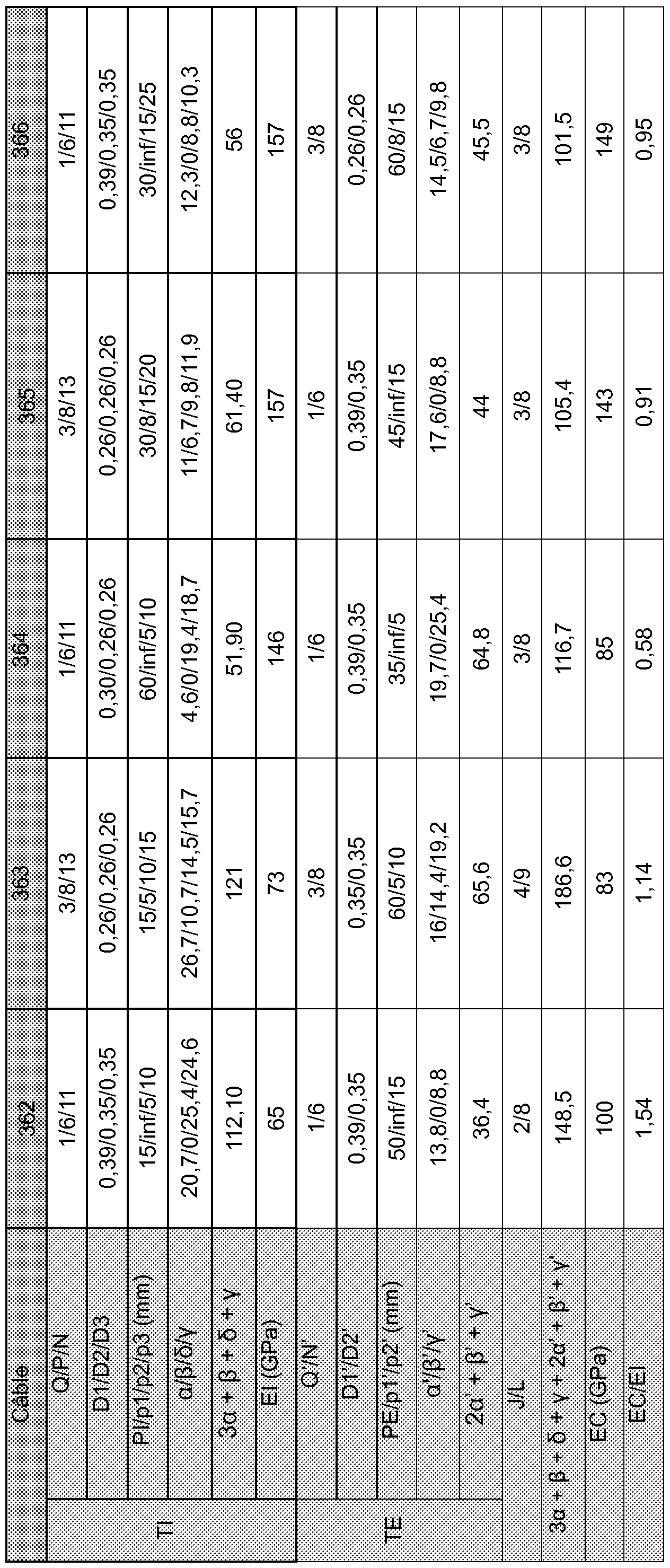
Tableau 5
Table 5
Claims
1. Câble multi-torons (60) à deux couches présentant un module EC et comprenant : A two-layer multi-strand cable (60) having an EC module and comprising:
- une couche interne (Cl) du câble constituée de J>1 torons internes (Tl) enroulés en hélice, chaque toron interne (Tl) comprenant : an inner layer (Cl) of the cable consisting of J> 1 internal strands (Tl) wound helically, each inner strand (Tl) comprising:
• une couche interne (C1 ) constituée de Q>1 fils internes (F 1 ), et An inner layer (C1) consisting of Q> 1 internal wires (F 1), and
• une couche externe (C2; C3) constituée de N>1 fils externes (F2; F3) enroulés autour de la couche interne (C1 ), An outer layer (C2; C3) consisting of N> 1 external wires (F2; F3) wound around the inner layer (C1),
- une couche externe (CE) du câble constituée de L>1 torons externes (TE) enroulés autour de la couche interne (Cl) du câble, chaque toron externe (TE) comprenant : an outer layer (CE) of the cable consisting of L> 1 outer strands (TE) wound around the inner layer (Cl) of the cable, each outer strand (TE) comprising:
• une couche interne (CT) constituée de Q’>1 fils internes (FT), An inner layer (CT) consisting of Q '> 1 internal wires (FT),
• une couche externe (C2’; C3’) constituée de N’>1 fils externes (F2’; F3’) enroulés autour de la couche interne (C1’), An outer layer (C2 '; C3') consisting of N '> 1 external wires (F2'; F3 ') wound around the inner layer (C1'),
caractérisé en ce que 50 GPa < EC < 160 GPa. characterized in that 50 GPa <EC <160 GPa.
2. Câble (60) selon la revendication précédente, dans lequel, la couche interne (Cl) du câble présentant un module El, 25 GPa < El < 180 GPa. 2. Cable (60) according to the preceding claim, wherein, the inner layer (Cl) of the cable having a module El, 25 GPa <El <180 GPa.
3. Câble (60) selon la revendication 1 ou 2, dans lequel, la couche interne (Cl) du câble présentant un module El, 0,60 < EC/EI < 1 ,20. 3. Cable (60) according to claim 1 or 2, wherein, the inner layer (Cl) of the cable having a module El, 0.60 <EC / EI <1, 20.
4. Câble (60) selon la revendication 1 ou 2, dans lequel EC/EI < 0,59 ou 1 ,21 < EC/EI, de préférence 0,40 < EC/EI < 0,59 ou 1 ,21 < EC/EI < 3,00. 4. Cable (60) according to claim 1 or 2, wherein EC / EI <0.59 or 1, 21 <EC / EI, preferably 0.40 <EC / EI <0.59 or 1, 21 <EC / EI <3.00.
5. Câble (60) selon l’une quelconque des revendications 1 à 4, dans lequel 50 GPa < EC < 89 GPa. The cable (60) according to any one of claims 1 to 4, wherein 50 GPa <EC <89 GPa.
6. Câble (60) selon la revendication précédente, dans lequel 36 GPa < El < 175 6. Cable (60) according to the preceding claim, wherein 36 GPa <El <175
GPa. GPa.
7. Câble (60) selon l’une quelconque des revendications 1 à 4, dans lequel 90 GPa < EC < 130 GPa. The cable (60) according to any one of claims 1 to 4, wherein 90 GPa <EC <130 GPa.
8. Câble (60) selon la revendication précédente, dans lequel 25 GPa < El < 180 GPa, de préférence 64 GPa < El < 180 GPa. 8. Cable (60) according to the preceding claim, wherein 25 GPa <El <180 GPa, preferably 64 GPa <El <180 GPa.
9. Câble (60) selon l’une quelconque des revendications 1 à 4, dans lequel 131 GPa < EC < 160 GPa. The cable (60) according to any one of claims 1 to 4, wherein 131 GPa <EC <160 GPa.
10. Câble (60) selon la revendication précédente, dans lequel 78 GPa < El < 180 GPa, de préférence 100 GPa < El < 180 GPa. 10. Cable (60) according to the preceding claim, wherein 78 GPa <El <180 GPa, preferably 100 GPa <El <180 GPa.
1 1. Câble (60) selon l’une quelconque des revendications précédentes, dans lequel J=2, 3 ou 4, de préférence J=3 ou 4. A cable (60) according to any one of the preceding claims, wherein J = 2, 3 or 4, preferably J = 3 or 4.
12. Câble (60) selon l’une quelconque des revendications précédentes, dans lequel L=7, 8, 9 ou 10, de préférence L=8, 9 ou 10 et plus préférentiellement L=8 ou 9.
12. Cable (60) according to any one of the preceding claims, wherein L = 7, 8, 9 or 10, preferably L = 8, 9 or 10 and more preferably L = 8 or 9.
13. Câble (60) selon l’une quelconque des revendications précédentes, dans lequel la couche externe (CE) du câble est désaturée. The cable (60) according to any of the preceding claims, wherein the outer layer (CE) of the cable is desaturated.
14. Pneumatique (10), caractérisé en ce qu’il comprend un câble (60) selon l’une quelconque des revendications précédentes. 14. Pneumatic tire (10), characterized in that it comprises a cable (60) according to any one of the preceding claims.
15. Pneumatique (10) selon la revendication précédente, comprenant une armature de carcasse (24) ancrée dans deux bourrelets (18) et surmontée radialement par une armature de sommet (14) elle-même surmontée d'une bande de roulement (22), l’armature de sommet (14) étant réunie auxdits bourrelets (18) par deux flancs (16), l’armature de sommet (14) comprenant au moins un câble (60) selon l’une quelconque des revendications 1 à 13.
15. Pneumatic tire (10) according to the preceding claim, comprising a carcass reinforcement (24) anchored in two beads (18) and radially surmounted by a crown reinforcement (14) itself surmounted by a tread (22). the crown reinforcement (14) being joined to said beads (18) by two flanks (16), the crown reinforcement (14) comprising at least one cable (60) according to any one of claims 1 to 13.
Priority Applications (4)
| Application Number | Priority Date | Filing Date | Title |
|---|---|---|---|
| CN201880088494.XA CN111684127A (en) | 2017-12-19 | 2018-12-19 | Double-layer multi-strand cord with very low, low and medium modulus |
| JP2020533826A JP7330190B2 (en) | 2017-12-19 | 2018-12-19 | Two-layer multi-strand cord with ultra-low, low, and medium modulus |
| EP18833992.3A EP3728727A1 (en) | 2017-12-19 | 2018-12-19 | Two-layer multi-strand cables having very low, low and medium modulus |
| US16/956,075 US11591750B2 (en) | 2017-12-19 | 2018-12-19 | Two-layer multi-strand cables having very low, low and medium modulus |
Applications Claiming Priority (2)
| Application Number | Priority Date | Filing Date | Title |
|---|---|---|---|
| FR1762496 | 2017-12-19 | ||
| FR1762496 | 2017-12-19 |
Publications (1)
| Publication Number | Publication Date |
|---|---|
| WO2019122720A1 true WO2019122720A1 (en) | 2019-06-27 |
Family
ID=62143274
Family Applications (1)
| Application Number | Title | Priority Date | Filing Date |
|---|---|---|---|
| PCT/FR2018/053416 WO2019122720A1 (en) | 2017-12-19 | 2018-12-19 | Two-layer multi-strand cables having very low, low and medium modulus |
Country Status (5)
| Country | Link |
|---|---|
| US (1) | US11591750B2 (en) |
| EP (1) | EP3728727A1 (en) |
| JP (1) | JP7330190B2 (en) |
| CN (1) | CN111684127A (en) |
| WO (1) | WO2019122720A1 (en) |
Cited By (2)
| Publication number | Priority date | Publication date | Assignee | Title |
|---|---|---|---|---|
| FR3122674A1 (en) * | 2021-05-07 | 2022-11-11 | Compagnie Generale Des Etablissements Michelin | Two-Layer Multi-Strand Rope with Improved Areal Breaking Energy |
| WO2023110581A1 (en) * | 2021-12-16 | 2023-06-22 | Compagnie Generale Des Etablissements Michelin | Double-layer multi-strand cord having improved bending endurance |
Families Citing this family (5)
| Publication number | Priority date | Publication date | Assignee | Title |
|---|---|---|---|---|
| WO2019122724A1 (en) | 2017-12-19 | 2019-06-27 | Compagnie Generale Des Etablissements Michelin | Two-layer multi-strand cords having very low, low and medium moduli |
| EP3728728B1 (en) | 2017-12-19 | 2022-07-20 | Compagnie Generale Des Etablissements Michelin | Two-layer multi-strand cords having very low, low and medium moduli |
| JP7309715B2 (en) * | 2017-12-19 | 2023-07-18 | コンパニー ゼネラール デ エタブリッスマン ミシュラン | Two-layer multi-strand cord with ultra-low, low, and medium modulus |
| JP7330191B2 (en) | 2017-12-19 | 2023-08-21 | コンパニー ゼネラール デ エタブリッスマン ミシュラン | Two-layer multi-strand cord with ultra-low, low, and medium modulus |
| FR3103500A1 (en) * | 2019-11-22 | 2021-05-28 | Compagnie Generale Des Etablissements Michelin | Two-layer multi-strand cable with improved surface fracture energy |
Citations (11)
| Publication number | Priority date | Publication date | Assignee | Title |
|---|---|---|---|---|
| DE6937562U (en) * | 1969-09-24 | 1970-01-22 | Gustav Wolf Seil Und Drahtwerk | MULTIPLE STRAND OR ROPE, PREFERRED FOR REINFORCEMENT FOR RUBBER OR PLASTIC PRODUCTS |
| FR2419182A1 (en) | 1978-03-10 | 1979-10-05 | Michelin & Cie | RADIAL CARCASS TIRE, ESPECIALLY FOR CIVIL ENGINEERING VEHICLES |
| FR2419181A1 (en) | 1978-03-10 | 1979-10-05 | Michelin & Cie | IMPROVEMENTS TO RADIAL CARCASE TIRES |
| US5843583A (en) | 1996-02-15 | 1998-12-01 | N.V. Bekaert S.A. | Cord with high non-structural elongation |
| WO2005014925A1 (en) | 2003-07-22 | 2005-02-17 | N.V. Bekaert S.A. | Hybrid high elongation cord |
| WO2007090603A1 (en) | 2006-02-09 | 2007-08-16 | Societe De Technologie Michelin | Resilient composite tyre cord |
| WO2008026271A1 (en) | 2006-08-31 | 2008-03-06 | Bridgestone Corporation | Rubber reinforcing steel cord and pneumatic radial tire |
| FR2947574A1 (en) * | 2009-07-03 | 2011-01-07 | Michelin Soc Tech | CABLE MULTITORONS WHOSE ELEMENTARY TORONES ARE CABLES WITH TWO LAYERS GOMMES IN SITU. |
| WO2013174897A1 (en) * | 2012-05-25 | 2013-11-28 | Compagnie Generale Des Etablissements Michelin | Two-layer multi-strand metal cable |
| WO2014048897A1 (en) * | 2012-09-26 | 2014-04-03 | Compagnie Generale Des Etablissements Michelin | Tyre for heavy civil engineering vehicle |
| WO2015090920A1 (en) | 2013-12-16 | 2015-06-25 | Compagnie Generale Des Etablissements Michelin | Two-layer multi-strand metal cable |
Family Cites Families (25)
| Publication number | Priority date | Publication date | Assignee | Title |
|---|---|---|---|---|
| CA2109904C (en) | 1992-12-18 | 2004-09-14 | Pol Bruyneel | Multi-strand steel cord |
| JP3819550B2 (en) | 1997-08-06 | 2006-09-13 | 株式会社ブリヂストン | Steel cords for reinforcing rubber articles and pneumatic tires |
| JP4401005B2 (en) | 2000-07-12 | 2010-01-20 | 株式会社ブリヂストン | Steel cord for reinforcing rubber articles and pneumatic tire using the same |
| JP4351558B2 (en) | 2004-03-04 | 2009-10-28 | 株式会社ブリヂストン | Steel cord for reinforcing rubber articles and pneumatic tire using the same |
| JP4553778B2 (en) | 2005-04-07 | 2010-09-29 | 株式会社ブリヂストン | Steel cord for rubber reinforcement and pneumatic radial tire |
| JP4628166B2 (en) | 2005-04-14 | 2011-02-09 | 株式会社ブリヂストン | Steel cord for rubber reinforcement and pneumatic radial tire |
| JP4628239B2 (en) | 2005-10-13 | 2011-02-09 | 株式会社ブリヂストン | Steel cords for reinforcing rubber articles and pneumatic radial tires |
| EP2184401A4 (en) | 2007-07-17 | 2013-09-18 | Bridgestone Corp | Cord, process for producing the same, and composite of cord with rubber |
| JP5322262B2 (en) * | 2008-03-28 | 2013-10-23 | 金井 宏彰 | Steel cord and steel cord group composed of this steel cord |
| JP5847990B2 (en) * | 2008-11-14 | 2016-01-27 | 株式会社ブリヂストン | Steel cords for reinforcing rubber articles and pneumatic tires |
| EP2504485B1 (en) | 2009-11-27 | 2014-07-30 | NV Bekaert SA | Open multi-strand cord |
| BR112013015146A2 (en) * | 2010-12-16 | 2016-09-27 | Bridgestone Corp | steel cord to reinforce rubber and pneumatic article using the same |
| JP5814179B2 (en) * | 2012-05-10 | 2015-11-17 | 株式会社ブリヂストン | Steel cord for reinforcing rubber articles and tire using the same |
| FR2990962B1 (en) | 2012-05-25 | 2014-06-27 | Michelin & Cie | METHOD FOR MANUFACTURING TWO-LAYER MULTI-TONE METAL CABLE |
| JP2015010309A (en) * | 2013-07-02 | 2015-01-19 | 株式会社ブリヂストン | Tire cord, reinforcing material for tire, and pneumatic tire |
| US10906353B2 (en) | 2014-07-28 | 2021-02-02 | Bridgestone Corporation | Steel cord for reinforcing rubber article |
| US10895037B2 (en) | 2014-07-28 | 2021-01-19 | Bridgestone Corporation | Steel cord for reinforcing rubber article |
| ES2743486T5 (en) | 2014-07-28 | 2023-04-10 | Bridgestone Corp | Steel cord to reinforce a rubber article |
| KR101601202B1 (en) * | 2014-09-23 | 2016-03-21 | 금호타이어 주식회사 | Passenger radial tires with ultra fine steel cord |
| FR3033287B1 (en) * | 2015-03-05 | 2017-03-10 | Michelin & Cie | PNEUMATIC TOP REINFORCING FOR HEAVY VEHICLE TYPE GENIE CIVIL |
| CN110546324B (en) * | 2017-04-28 | 2022-02-18 | 株式会社普利司通 | Steel cord for reinforcing rubber article, method for producing same, and tire |
| WO2019122724A1 (en) | 2017-12-19 | 2019-06-27 | Compagnie Generale Des Etablissements Michelin | Two-layer multi-strand cords having very low, low and medium moduli |
| JP7330191B2 (en) | 2017-12-19 | 2023-08-21 | コンパニー ゼネラール デ エタブリッスマン ミシュラン | Two-layer multi-strand cord with ultra-low, low, and medium modulus |
| JP7309715B2 (en) | 2017-12-19 | 2023-07-18 | コンパニー ゼネラール デ エタブリッスマン ミシュラン | Two-layer multi-strand cord with ultra-low, low, and medium modulus |
| EP3728728B1 (en) | 2017-12-19 | 2022-07-20 | Compagnie Generale Des Etablissements Michelin | Two-layer multi-strand cords having very low, low and medium moduli |
-
2018
- 2018-12-19 JP JP2020533826A patent/JP7330190B2/en active Active
- 2018-12-19 WO PCT/FR2018/053416 patent/WO2019122720A1/en unknown
- 2018-12-19 US US16/956,075 patent/US11591750B2/en active Active
- 2018-12-19 EP EP18833992.3A patent/EP3728727A1/en active Pending
- 2018-12-19 CN CN201880088494.XA patent/CN111684127A/en active Pending
Patent Citations (11)
| Publication number | Priority date | Publication date | Assignee | Title |
|---|---|---|---|---|
| DE6937562U (en) * | 1969-09-24 | 1970-01-22 | Gustav Wolf Seil Und Drahtwerk | MULTIPLE STRAND OR ROPE, PREFERRED FOR REINFORCEMENT FOR RUBBER OR PLASTIC PRODUCTS |
| FR2419182A1 (en) | 1978-03-10 | 1979-10-05 | Michelin & Cie | RADIAL CARCASS TIRE, ESPECIALLY FOR CIVIL ENGINEERING VEHICLES |
| FR2419181A1 (en) | 1978-03-10 | 1979-10-05 | Michelin & Cie | IMPROVEMENTS TO RADIAL CARCASE TIRES |
| US5843583A (en) | 1996-02-15 | 1998-12-01 | N.V. Bekaert S.A. | Cord with high non-structural elongation |
| WO2005014925A1 (en) | 2003-07-22 | 2005-02-17 | N.V. Bekaert S.A. | Hybrid high elongation cord |
| WO2007090603A1 (en) | 2006-02-09 | 2007-08-16 | Societe De Technologie Michelin | Resilient composite tyre cord |
| WO2008026271A1 (en) | 2006-08-31 | 2008-03-06 | Bridgestone Corporation | Rubber reinforcing steel cord and pneumatic radial tire |
| FR2947574A1 (en) * | 2009-07-03 | 2011-01-07 | Michelin Soc Tech | CABLE MULTITORONS WHOSE ELEMENTARY TORONES ARE CABLES WITH TWO LAYERS GOMMES IN SITU. |
| WO2013174897A1 (en) * | 2012-05-25 | 2013-11-28 | Compagnie Generale Des Etablissements Michelin | Two-layer multi-strand metal cable |
| WO2014048897A1 (en) * | 2012-09-26 | 2014-04-03 | Compagnie Generale Des Etablissements Michelin | Tyre for heavy civil engineering vehicle |
| WO2015090920A1 (en) | 2013-12-16 | 2015-06-25 | Compagnie Generale Des Etablissements Michelin | Two-layer multi-strand metal cable |
Cited By (3)
| Publication number | Priority date | Publication date | Assignee | Title |
|---|---|---|---|---|
| FR3122674A1 (en) * | 2021-05-07 | 2022-11-11 | Compagnie Generale Des Etablissements Michelin | Two-Layer Multi-Strand Rope with Improved Areal Breaking Energy |
| WO2023110581A1 (en) * | 2021-12-16 | 2023-06-22 | Compagnie Generale Des Etablissements Michelin | Double-layer multi-strand cord having improved bending endurance |
| FR3130858A1 (en) * | 2021-12-16 | 2023-06-23 | Compagnie Generale Des Etablissements Michelin | Two-layer multi-strand rope with improved flexural endurance |
Also Published As
| Publication number | Publication date |
|---|---|
| EP3728727A1 (en) | 2020-10-28 |
| CN111684127A (en) | 2020-09-18 |
| JP2021507136A (en) | 2021-02-22 |
| US20210071359A1 (en) | 2021-03-11 |
| JP7330190B2 (en) | 2023-08-21 |
| US11591750B2 (en) | 2023-02-28 |
Similar Documents
| Publication | Publication Date | Title |
|---|---|---|
| EP3728728B1 (en) | Two-layer multi-strand cords having very low, low and medium moduli | |
| EP3728731B1 (en) | Two-layer multi-strand cords having very low, low and medium moduli | |
| EP3728730B1 (en) | Two-layer multi-strand cords having very low, low and medium moduli | |
| EP3728729B1 (en) | Two-layer multi-strand cords having very low, low and medium moduli | |
| WO2019122720A1 (en) | Two-layer multi-strand cables having very low, low and medium modulus | |
| EP4061996B1 (en) | Two-layer multi-strand cable having an improved surface energy-to-break | |
| WO2021260302A1 (en) | Double-layer multi-strand cable having improved bending endurance | |
| WO2021260304A1 (en) | Double-layer multi-strand cable having improved bending endurance | |
| WO2021260303A1 (en) | Double-layer multi-strand cable having improved bending endurance | |
| EP4172405A1 (en) | Double-layer multi-strand cable having improved bending endurance | |
| EP4058628B1 (en) | Two-layer multi-strand cable having a sheathed inner layer and an improved performance | |
| EP4334524A1 (en) | Two-layer multi-strand cable having improved surface fracture energy | |
| WO2022234201A1 (en) | Two-layer multi-strand cable having improved fracture surface energy | |
| WO2022234202A1 (en) | Two-layer multi-strand cable having improved surface fracture energy | |
| FR3122678A1 (en) | Two-Layer Multi-Strand Rope with Improved Areal Breaking Energy | |
| FR3122674A1 (en) | Two-Layer Multi-Strand Rope with Improved Areal Breaking Energy | |
| FR3122675A1 (en) | Two-Layer Multi-Strand Rope with Improved Areal Breaking Energy | |
| FR3122673A1 (en) | Two-Layer Multi-Strand Rope with Improved Areal Breaking Energy | |
| WO2023110581A1 (en) | Double-layer multi-strand cord having improved bending endurance |
Legal Events
| Date | Code | Title | Description |
|---|---|---|---|
| 121 | Ep: the epo has been informed by wipo that ep was designated in this application |
Ref document number: 18833992 Country of ref document: EP Kind code of ref document: A1 |
|
| ENP | Entry into the national phase |
Ref document number: 2020533826 Country of ref document: JP Kind code of ref document: A |
|
| NENP | Non-entry into the national phase |
Ref country code: DE |
|
| ENP | Entry into the national phase |
Ref document number: 2018833992 Country of ref document: EP Effective date: 20200720 |