WO2019116781A1 - 車両用暖房装置 - Google Patents
車両用暖房装置 Download PDFInfo
- Publication number
- WO2019116781A1 WO2019116781A1 PCT/JP2018/041080 JP2018041080W WO2019116781A1 WO 2019116781 A1 WO2019116781 A1 WO 2019116781A1 JP 2018041080 W JP2018041080 W JP 2018041080W WO 2019116781 A1 WO2019116781 A1 WO 2019116781A1
- Authority
- WO
- WIPO (PCT)
- Prior art keywords
- heating
- vehicle
- heat medium
- cooling water
- air
- Prior art date
- Legal status (The legal status is an assumption and is not a legal conclusion. Google has not performed a legal analysis and makes no representation as to the accuracy of the status listed.)
- Ceased
Links
Images


Classifications
-
- B—PERFORMING OPERATIONS; TRANSPORTING
- B60—VEHICLES IN GENERAL
- B60H—ARRANGEMENTS OF HEATING, COOLING, VENTILATING OR OTHER AIR-TREATING DEVICES SPECIALLY ADAPTED FOR PASSENGER OR GOODS SPACES OF VEHICLES
- B60H1/00—Heating, cooling or ventilating [HVAC] devices
- B60H1/02—Heating, cooling or ventilating [HVAC] devices the heat being derived from the propulsion plant
- B60H1/04—Heating, cooling or ventilating [HVAC] devices the heat being derived from the propulsion plant from cooling liquid of the plant
- B60H1/08—Heating, cooling or ventilating [HVAC] devices the heat being derived from the propulsion plant from cooling liquid of the plant from other radiator than main radiator
-
- B—PERFORMING OPERATIONS; TRANSPORTING
- B60—VEHICLES IN GENERAL
- B60H—ARRANGEMENTS OF HEATING, COOLING, VENTILATING OR OTHER AIR-TREATING DEVICES SPECIALLY ADAPTED FOR PASSENGER OR GOODS SPACES OF VEHICLES
- B60H1/00—Heating, cooling or ventilating [HVAC] devices
- B60H1/00642—Control systems or circuits; Control members or indication devices for heating, cooling or ventilating devices
- B60H1/00814—Control systems or circuits characterised by their output, for controlling particular components of the heating, cooling or ventilating installation
- B60H1/00878—Control systems or circuits characterised by their output, for controlling particular components of the heating, cooling or ventilating installation the components being temperature regulating devices
- B60H1/00899—Controlling the flow of liquid in a heat pump system
- B60H1/00921—Controlling the flow of liquid in a heat pump system where the flow direction of the refrigerant does not change and there is an extra subcondenser, e.g. in an air duct
-
- B—PERFORMING OPERATIONS; TRANSPORTING
- B60—VEHICLES IN GENERAL
- B60H—ARRANGEMENTS OF HEATING, COOLING, VENTILATING OR OTHER AIR-TREATING DEVICES SPECIALLY ADAPTED FOR PASSENGER OR GOODS SPACES OF VEHICLES
- B60H1/00—Heating, cooling or ventilating [HVAC] devices
- B60H1/02—Heating, cooling or ventilating [HVAC] devices the heat being derived from the propulsion plant
- B60H1/025—Heating, cooling or ventilating [HVAC] devices the heat being derived from the propulsion plant from both the cooling liquid and the exhaust gases of the propulsion plant
-
- B—PERFORMING OPERATIONS; TRANSPORTING
- B60—VEHICLES IN GENERAL
- B60H—ARRANGEMENTS OF HEATING, COOLING, VENTILATING OR OTHER AIR-TREATING DEVICES SPECIALLY ADAPTED FOR PASSENGER OR GOODS SPACES OF VEHICLES
- B60H1/00—Heating, cooling or ventilating [HVAC] devices
- B60H1/32—Cooling devices
- B60H1/3204—Cooling devices using compression
- B60H1/3228—Cooling devices using compression characterised by refrigerant circuit configurations
- B60H1/32281—Cooling devices using compression characterised by refrigerant circuit configurations comprising a single secondary circuit, e.g. at evaporator or condenser side
-
- B—PERFORMING OPERATIONS; TRANSPORTING
- B60—VEHICLES IN GENERAL
- B60H—ARRANGEMENTS OF HEATING, COOLING, VENTILATING OR OTHER AIR-TREATING DEVICES SPECIALLY ADAPTED FOR PASSENGER OR GOODS SPACES OF VEHICLES
- B60H3/00—Other air-treating devices
- B60H3/02—Moistening ; Devices influencing humidity levels, i.e. humidity control
- B60H3/024—Moistening ; Devices influencing humidity levels, i.e. humidity control for only dehumidifying the air
-
- B—PERFORMING OPERATIONS; TRANSPORTING
- B60—VEHICLES IN GENERAL
- B60H—ARRANGEMENTS OF HEATING, COOLING, VENTILATING OR OTHER AIR-TREATING DEVICES SPECIALLY ADAPTED FOR PASSENGER OR GOODS SPACES OF VEHICLES
- B60H1/00—Heating, cooling or ventilating [HVAC] devices
- B60H1/00642—Control systems or circuits; Control members or indication devices for heating, cooling or ventilating devices
- B60H1/00814—Control systems or circuits characterised by their output, for controlling particular components of the heating, cooling or ventilating installation
- B60H1/00878—Control systems or circuits characterised by their output, for controlling particular components of the heating, cooling or ventilating installation the components being temperature regulating devices
- B60H2001/00928—Control systems or circuits characterised by their output, for controlling particular components of the heating, cooling or ventilating installation the components being temperature regulating devices comprising a secondary circuit
Definitions
- the present disclosure relates to a vehicle heating device for heating a vehicle interior.
- the vehicle heating device is configured to heat the blown air supplied to the space to be heated.
- the disclosure indicated in patent documents 1 is known ing.
- the heating system described in Patent Document 1 includes a cooling water circuit having a vehicle engine, a heater core, a heater, and a three-way valve, and dissipates the heat of the cooling water to the blast air by the heater core. This achieves heating of the vehicle interior.
- the cooling water circuit in the heating system is configured to operate the three-way valve according to the operating state of the vehicle engine and the temperature of the cooling liquid to switch from a plurality of circuit configurations to one circuit configuration. Specifically, when the vehicle engine is operating, it is switched to the circuit configuration circulating the vehicle engine and the heater core, and when the vehicle engine is not activated, it is switched to the circuit configuration not passing through the vehicle engine .
- a hybrid vehicle has a mode of traveling with a vehicle engine as a drive source and a mode of stopping the vehicle engine and traveling with another drive source (for example, a motor). For this reason, the heating system of patent document 1 is applicable.
- the cooling water passes through the heater or the like in any of the plurality of circuit configurations.
- the heater or the like is disposed as an alternative heat source when the vehicle engine is stopped.
- the present disclosure is made in view of these points, and when heating a vehicle engine, it is possible to suppress a decrease in heating performance due to an increase in water flow resistance while utilizing exhaust heat of the vehicle engine. Intended to be provided.
- a vehicle heating apparatus is mounted on a vehicle having a power plant.
- a heating system for a vehicle includes a blower for blowing the blowing air into a compartment, which is a space to be heated, and a heating medium circuit connected with a heater core for heating the blowing air blown by the blower with the heat medium. And a circulating device for circulating the heat medium in the heat medium circuit.
- the heat medium circuit is disposed in parallel with the first flow path connected to the heater core via the power plant and the first flow path, and is connected to the heater core via the heat source device different from the power plant. And 2 channels.
- the vehicle heating apparatus further includes a flow rate adjustment unit that adjusts a first flow rate of the heat medium flowing into the first flow path and a second flow rate of the heat medium flowing into the second flow path.
- the flow rate adjustment unit adjusts the first flow rate to be larger than the second flow rate when the power plant is operating.
- the vehicle heating device can recover the heat generated in the power unit by the heat medium flowing through the first flow passage, can heat the blowing air by the heater core, and can heat the vehicle interior. Further, the vehicle heating device can recover the heat generated in the heat source device by the heat medium flowing through the second flow passage, can heat the blowing air by the heater core, and can heat the vehicle interior.
- the vehicle heating device can recover the exhaust heat generated with the operation of the power unit, and can be used for heating the vehicle interior.
- the first flow rate of the heat medium via the power unit is made larger than the second flow rate of the heat medium via the heat source device.
- the vehicle heating device can reduce the water flow resistance compared to the case where the entire amount of heat medium passes through the power device and the heat source device, so the heating performance related to the vehicle heating device decreases. Can be suppressed.
- the vehicle heating device can also suppress the temperature decrease of the heat medium in the heat source device in the stopped state by flowing the heat medium at the second flow rate to the heat source device.
- the vehicle heating device performs heating of the vehicle interior again using the heat source device, the heat medium which is excessively cooled is prevented from flowing into the heater core, and the heat shock load in the heater core is reduced. be able to.
- the vehicle air conditioner 1 according to the first embodiment is applied to an internal combustion engine (i.e., an engine EG) and a hybrid vehicle that obtains a driving force for traveling from a traveling electric motor.
- an internal combustion engine i.e., an engine EG
- a hybrid vehicle that obtains a driving force for traveling from a traveling electric motor.
- the hybrid vehicle is configured as a so-called plug-in hybrid vehicle. Therefore, the hybrid vehicle is configured to be able to charge the battery (that is, the battery 25) mounted on the vehicle when the vehicle is stopped, with the electric power supplied from the external power supply (for example, a commercial power supply).
- the external power supply for example, a commercial power supply.
- a lithium ion battery can be used as this battery.
- the driving force output from the engine EG is used not only for driving the vehicle but also for operating the generator.
- the hybrid vehicle can store the power generated by the generator and the power supplied from the external power source in the battery 25.
- the power stored in the battery 25 is not limited to the traveling electric motor. , And supplied to various in-vehicle devices mounted in the hybrid vehicle.
- the hybrid vehicle travels in the EV travel mode when the remaining charge amount of the battery 25 is equal to or greater than a predetermined travel reference remaining amount, as at the start of travel.
- the EV travel mode means a travel mode in which the vehicle is traveled by driving the traveling electric motor by the power of the battery 25.
- the hybrid vehicle travels in the HV traveling mode when the remaining charge amount of the battery 25 is lower than the traveling reference remaining amount while the vehicle is traveling.
- the HV traveling mode is a traveling mode in which the vehicle is traveled mainly by the driving force output by the engine EG. However, when the vehicle traveling load is high, the traveling electric motor is operated to assist the engine EG. Do.
- the fuel consumption of the engine EG is obtained with respect to a normal vehicle which obtains the driving force for traveling the vehicle from only the engine EG by thus switching between the EV travel mode and the HV travel mode. To improve vehicle fuel efficiency.
- the vehicle air conditioner 1 can switch to a plurality of operation modes such as a heating mode, a cooling mode, and a dehumidifying heating mode in order to realize comfortable air conditioning in the vehicle interior of the hybrid vehicle. Therefore, the vehicle air conditioner 1 corresponds to the vehicle heating device according to the present disclosure.
- the vehicle air conditioner 1 has a function of cooling the battery 25 so as to maintain the temperature of the battery 25 within the appropriate temperature range.
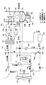
- the vehicle air conditioner 1 includes a refrigeration cycle apparatus 10, an indoor air conditioning unit 30, a heating side heat medium circuit 40, a control device 50, and the like.
- the refrigeration cycle apparatus 10 is an apparatus for adjusting the temperature of blowing air by a vapor compression refrigeration cycle.
- the indoor air conditioning unit 30 blows the blowing air into the vehicle compartment of the hybrid vehicle.
- the heating side heat medium circuit 40 is a heat medium circuit for heating the blowing air through the cooling water which is a heat medium.
- the refrigeration cycle apparatus 10 has a vapor compression refrigeration cycle, and functions to heat or cool the blast air in order to perform air conditioning of the vehicle interior. Furthermore, the refrigeration cycle apparatus 10 functions to cool the battery 25 by the low pressure refrigerant of the refrigeration cycle.
- the refrigeration cycle apparatus 10 is configured to be able to switch between a refrigerant circuit in the cooling mode, a refrigerant circuit in the dehumidifying and heating mode, and a refrigerant circuit in the heating mode in order to perform air conditioning of the vehicle interior.
- the cooling mode is an operation mode for cooling the vehicle interior by cooling the blown air and blowing it out into the vehicle interior.
- the dehumidifying and heating mode is an operation mode for dehumidifying and heating the passenger compartment by reheating the cooled and dehumidified air to blow it out into the passenger compartment.
- the heating mode is an operation mode for heating the cabin by heating the blown air and blowing it out into the cabin.
- the flow of the refrigerant in the refrigerant circuit in the cooling mode is indicated by a white arrow. Further, the flow of the refrigerant in the refrigerant circuit in the dehumidifying and heating mode is indicated by hatched hatched arrows. Furthermore, the flow of the refrigerant in the refrigerant circuit in the heating mode is indicated by a solid arrow.
- an HFC-based refrigerant (specifically, R134a) is adopted as the refrigerant, and the pressure of the discharged refrigerant discharged from the compressor 11 does not exceed the critical pressure of the refrigerant. It constitutes a critical refrigeration cycle.
- Refrigerant oil for lubricating the compressor 11 is mixed in the refrigerant, and a part of the refrigerant oil circulates in the cycle together with the refrigerant.
- the refrigeration cycle apparatus 10 includes the compressor 11, the radiator 12, the first expansion valve 14 a, the second expansion valve 14 b, the outdoor heat exchanger 16, the check valve 17, and the indoor evaporator 18. , An evaporation pressure control valve 19 and an accumulator 20.
- the compressor 11 sucks, compresses and discharges the refrigerant in the refrigeration cycle apparatus 10.
- the said compressor 11 is comprised by the electric compressor which rotationally drives the fixed displacement type compression mechanism to which discharge displacement was fixed by an electric motor.
- the compressor 11 functions as a compressor in the present disclosure.
- the compressor 11 is disposed in a vehicle bonnet.
- the refrigerant inlet side of the radiator 12 is connected to the discharge port of the compressor 11.
- the radiator 12 condenses the high-pressure refrigerant by exchanging heat between the high-pressure refrigerant discharged from the compressor 11 and the coolant, which is a heat medium circulating through the heating-side heat medium circuit 40 described later.
- the radiator 12 is configured by a water-refrigerant heat exchanger, and functions as a radiator in the present disclosure.
- the heating-side heat medium circuit 40 constituting the vehicle air conditioner 1 will be described in detail later with reference to the drawings.
- the inlet side of the first three-way joint 13 a is connected to the refrigerant outlet side of the radiator 12.
- the first three-way joint 13a has three inlets and outlets communicating with each other.
- a three-way joint one formed by joining a plurality of pipes, or one formed by providing a plurality of refrigerant passages in a metal block or a resin block can be adopted.
- the refrigeration cycle apparatus 10 has a second three-way joint 13b to a sixth three-way joint 13f as described later.
- the basic configuration of the second three-way joint 13b to the sixth three-way joint 13f is the same as that of the first three-way joint 13a.
- the inlet side of the first expansion valve 14a is connected to one outlet of the first three-way joint 13a.
- One inflow side of the second three-way joint 13 b is connected to the other outlet of the first three-way joint 13 a.
- a first on-off valve 15a is disposed in the refrigerant passage connecting the other outlet side of the first three-way joint 13a and the one inlet side of the second three-way joint 13b.
- the first on-off valve 15a is an electromagnetic valve that opens and closes a refrigerant passage that connects the other outlet side of the first three-way joint 13a and the one inlet side of the second three-way joint 13b.
- the refrigeration cycle apparatus 10 has a second on-off valve 15 b as described later.
- the basic configuration of the second on-off valve 15b is the same as that of the first on-off valve 15a.
- the first on-off valve 15a and the second on-off valve 15b can switch the refrigerant circuit in each operation mode described above by opening and closing the refrigerant passage.
- the first on-off valve 15a and the second on-off valve 15b are refrigerant circuit switching devices that switch the refrigerant circuit of the cycle.
- the operation of the first on-off valve 15 a and the second on-off valve 15 b is controlled by the control voltage output from the control device 50.
- the first expansion valve 14 a is a pressure reducing device that reduces the pressure of the high pressure refrigerant flowing out of the radiator 12 at least in the heating mode.
- the first expansion valve 14a is an electric variable throttle mechanism configured to include a valve body configured to be capable of changing the throttle opening and an electric actuator that changes the opening degree of the valve.
- the first expansion valve 14 a functions as a pressure reducing unit in the present disclosure.
- the refrigeration cycle apparatus 10 has a second expansion valve 14 b as described later.
- the basic configuration of the second expansion valve 14b is the same as that of the first expansion valve 14a.
- the first expansion valve 14 a and the second expansion valve 14 b are fully open functions that function as a simple refrigerant passage with almost no flow control function and refrigerant pressure reducing function by fully opening the valve opening degree, and the valve opening degree Has a fully closed function of closing the refrigerant passage by fully closing the valve.
- the first expansion valve 14 a and the second expansion valve 14 b can switch the refrigerant circuits in the above-described operation modes by the fully open function and the fully closed function. Therefore, the first expansion valve 14a and the second expansion valve 14b also have a function as a refrigerant circuit switching device.
- the operation of the first expansion valve 14 a and the second expansion valve 14 b is controlled by a control signal (control pulse) output from the control device 50.
- the refrigerant inlet side of the outdoor heat exchanger 16 is connected to the outlet of the first expansion valve 14a.
- the outdoor heat exchanger 16 is a heat exchanger that exchanges heat between the refrigerant flowing out of the first expansion valve 14a and the outside air blown by the outside air fan 16a.
- the outdoor heat exchanger 16 is disposed on the front side in the vehicle bonnet.
- the outdoor heat exchanger 16 functions as a radiator that dissipates the high pressure refrigerant at least in the cooling mode, and functions as an evaporator that evaporates the low pressure refrigerant at least in the heating mode. That is, the outdoor heat exchanger 16 corresponds to the evaporator in the present disclosure.
- the open air fan 16a is comprised by the electrically-driven air blower.
- the blowing capacity (ie, the number of rotations) of the outside air fan 16 a is controlled by the control voltage output from the control device 50.
- the inlet side of the third three-way joint 13 c is connected to the refrigerant outlet of the outdoor heat exchanger 16.
- One inlet side of the fourth three-way joint 13d is connected to one outlet of the third three-way joint 13c.
- a second on-off valve 15b is disposed in a refrigerant passage connecting one outlet side of the third three-way joint 13c and one inlet side of the fourth three-way joint 13d. By opening and closing the second on-off valve 15b, it is possible to switch the presence or absence of the refrigerant flow in the refrigerant passage.
- a check valve 17 is disposed in the refrigerant passage connecting the other outlet side of the third three-way joint 13c and the other inlet side of the second three-way joint 13b.
- the check valve 17 allows the refrigerant to flow from the third three-way joint 13c side (ie, the outdoor heat exchanger 16 side) to the second three-way joint 13b side (ie, the second expansion valve 14b and the radiator 12). And prohibits the flow of the refrigerant from the side of the second three-way joint 13b to the side of the third three-way joint 13c.
- the inlet side of the fifth three-way joint 13e is connected to the outlet of the second three-way joint 13b.
- the inlet side of the second expansion valve 14b is connected to one outlet of the fifth three-way joint 13e.
- the refrigerant inlet side of the water jacket of the battery 25 is connected to the other outlet of the fifth three-way joint 13e.
- the water jacket of the battery 25 is disposed so as to cover the outer surface of the battery 25 and has a refrigerant flow path therein. Therefore, the low-pressure refrigerant flowing out from the other outlet of the fifth three-way joint 13 e absorbs heat generated by the battery 25 to cool the battery 25.
- One inlet side of the sixth three-way joint 13 f is connected to the refrigerant outlet in the water jacket of the battery 25.
- the second expansion valve 14 b is an electric variable throttle mechanism that decompresses the refrigerant flowing out of the outdoor heat exchanger 16 at least in the cooling mode.
- the refrigerant inlet side of the indoor evaporator 18 is connected to the outlet side of the second expansion valve 14b.
- the indoor evaporator 18 is disposed in an air conditioning case 31 of an indoor air conditioning unit 30 described later.
- the indoor evaporator 18 exchanges heat between the low pressure refrigerant decompressed by the second expansion valve 14b and the air blown by the blower 32 at least in the cooling mode to evaporate the low pressure refrigerant, thereby absorbing the heat absorption to the low pressure refrigerant. It is a heat exchanger for cooling which cools blowing air by making it exhibit.
- the other inlet side of the sixth three-way joint 13 f is connected to the refrigerant outlet of the indoor evaporator 18.
- the inlet side of the evaporation pressure control valve 19 is connected to the outlet of the sixth three-way joint 13 f.
- the evaporation pressure control valve 19 is configured by a mechanical variable throttle mechanism that increases the valve opening degree as the pressure of the refrigerant on the outlet side of the indoor evaporator 18 increases.
- the evaporation pressure control valve 19 functions to maintain the refrigerant evaporation pressure in the indoor evaporator 18 at or above a predetermined reference pressure in order to suppress the formation of frost on the indoor evaporator 18.
- the evaporation pressure adjusting valve 19 can maintain the refrigerant evaporation temperature in the indoor evaporator 18 at or above the reference temperature that can suppress the formation of frost on the indoor evaporator 18.
- the outlet of the evaporation pressure regulating valve 19 is connected to the other inlet side of the fourth three-way joint 13 d.
- the inlet side of the accumulator 20 is connected to the outlet of the fourth three-way joint 13d.
- the accumulator 20 is a gas-liquid separator that separates the gas-liquid of the refrigerant that has flowed into the inside and stores the surplus liquid-phase refrigerant in the cycle.
- the suction port side of the compressor 11 is connected to the gas phase refrigerant outlet of the accumulator 20.
- the indoor air conditioning unit 30 of the vehicle air conditioner 1 is for blowing the blowing air whose temperature has been adjusted by the refrigeration cycle apparatus 10 into the vehicle compartment.
- the indoor air conditioning unit 30 is disposed inside the instrument panel at the foremost part of the vehicle interior.
- the indoor air conditioning unit 30 is configured by housing a blower 32, an indoor evaporator 18, a heater core 43, and the like in an air conditioning case 31 forming an outer shell thereof. That is, in the indoor air conditioning unit 30, the indoor evaporator 18 and the heater core 43 are disposed in an air passage formed inside the air conditioning case 31.
- the air conditioning case 31 forms an air passage for blowing air blown into the vehicle compartment.
- the air conditioning case 31 has a certain degree of elasticity and is formed of a resin (for example, polypropylene) which is excellent in strength.
- An internal / external air switching device 33 is disposed on the most upstream side of the air flow in the air conditioning case 31.
- the inside / outside air switching device 33 switches and introduces the inside air (vehicle indoor air) and the outside air (air outside the vehicle) into the air conditioning case 31.
- the inside / outside air switching device 33 continuously adjusts the opening area of the inside air introduction port for introducing inside air into the air conditioning case 31 and the outside air introduction port for introducing outside air by means of the inside / outside air switching door Change the introduction rate with the introduction air volume of.
- the inside and outside air switching door is driven by an electric actuator for the inside and outside air switching door. The operation of the electric actuator is controlled by a control signal output from the controller 50.
- a blower 32 is disposed downstream of the inside / outside air switching device 33 in the flow of the blown air.
- the blower 32 is configured by an electric blower that drives a centrifugal multiblade fan by an electric motor.
- the blower 32 blows the air taken in via the inside / outside air switching device 33 toward the vehicle interior.
- the blowing capacity (i.e., the number of rotations) of the blower 32 is controlled by the control voltage output from the control device 50.
- the indoor evaporator 18 and the heater core 43 are disposed in this order with respect to the flow of the blowing air on the downstream side of the flow of the blowing air of the blower 32. That is, the indoor evaporator 18 is disposed upstream of the heater core 43 in the flow of the blown air.
- the heater core 43 is one of the constituent devices of the heating-side heat medium circuit 40, and exchanges heat between the cooling water circulating through the heating-side heat medium circuit 40 and the air that has passed through the indoor evaporator 18 to blow air. It is a heat exchanger for heating air. Details of the heating side heat medium circuit 40 including the heater core 43 will be described in detail later with reference to the drawings.
- a bypass passage 35 is provided in the air conditioning case 31.
- the bypass passage 35 is a passage for flowing the blown air after passing through the indoor evaporator 18 by bypassing the heater core 43.
- An air mix door 34 is disposed on the downstream side of the air flow of the indoor evaporator 18 in the air conditioning case 31 and on the upstream side of the air flow of the heater core 43.
- the air mix door 34 adjusts the air volume ratio between the air volume of the air passing through the heater core 43 and the air volume of the air passing through the bypass passage 35 among the air after passing through the indoor evaporator 18. It is.
- the air mix door 34 is driven by an electric actuator for the air mix door.
- the operation of the electric actuator is controlled by a control signal output from the controller 50.
- a mixing space is provided downstream of the heater core 43 and the bypass passage 35 in the flow of the blown air.
- the mixing space is a space for mixing the heated air by heat exchange with the cooling water by the heater core 43 and the unheated air that has passed through the bypass passage 35.
- an opening hole for blowing out the air mixed in the mixing space (that is, the air-conditioned air) into the vehicle interior which is the air conditioning target space is disposed.
- the face opening hole is an opening hole for blowing the conditioned air toward the upper body of the occupant in the vehicle compartment.
- the foot opening hole is an opening hole for blowing the conditioned air toward the feet of the occupant.
- the defroster opening hole is an opening hole for blowing the conditioned air toward the inner side surface of the vehicle front windshield.
- These face opening holes, foot opening holes, and defroster opening holes are respectively provided in the vehicle compartment via a duct that forms an air passage, face outlet, foot outlet, and defroster outlet (all not shown) )It is connected to the.
- the temperature of the conditioned air mixed in the mixing space is adjusted by adjusting the air volume ratio of the air volume passing the heater core 43 and the air volume passing the bypass passage 35 by the air mix door 34.
- the temperature of the air (air-conditioned air) blown out from the outlets into the vehicle compartment is adjusted.
- the face door, the foot door, and the defroster door are disposed on the upstream side of the air flow of the face opening hole, the foot opening hole, and the defroster opening hole, respectively.
- the face door adjusts the opening area of the face opening hole.
- the foot door adjusts the opening area of the foot opening hole.
- the defroster door adjusts the opening area of the defroster opening hole.
- These face door, foot door and defroster door constitute an outlet mode switching device for switching the outlet mode.
- these doors are connected to an electric actuator for driving the air outlet mode door via a link mechanism or the like, and are operated to rotate in conjunction with each other.
- the operation of the electric actuator is also controlled by a control signal output from the control device 50.
- the air outlet mode switched by the air outlet mode switching device includes a face mode, a bi-level mode, a foot mode, and the like.
- the face mode is an outlet mode in which the face outlet is fully opened and air is blown from the face outlet toward the upper body of the passenger in the vehicle compartment.
- the bi-level mode is an air outlet mode in which both the face air outlet and the foot air outlet are opened to blow air toward the upper body and the foot of the passenger in the vehicle compartment.
- the foot mode is an outlet mode in which the foot outlet is fully opened and the defroster outlet is opened by a small opening degree and air is mainly blown out from the foot outlet.
- the defroster mode can also be set by manually operating the blowout mode switching switch provided on the operation panel 60 by the occupant.
- the defroster mode is an air outlet mode in which air is blown out from the defroster air outlet to the inner surface of the vehicle windshield with the defroster air outlet fully open.
- the heating side heat medium circuit 40 is a heat medium circuit that circulates the heat medium between the radiator 12 of the refrigeration cycle apparatus 10 or the constituent devices of the hybrid vehicle and the heater core 43. Cooling water is used as a heat medium in the heating side heat medium circuit 40.
- the cooling water for example, water or an ethylene glycol aqueous solution can be employed.
- the heating side heat medium circuit 40 includes the radiator 12 of the refrigeration cycle apparatus 10, the engine EG, the heating side water pump 41, the water heating heater 42, and the heater core 43. have.
- these components are connected by a cooling water flow path, and a closed circuit in which the heat medium can circulate is formed.
- Engine EG is an internal combustion engine of the hybrid vehicle, and corresponds to a power plant in the present disclosure.
- the engine EG is disposed in the cooling water flow path of the heating side heat medium circuit 40, and is configured to be capable of exchanging heat with the cooling water.
- an engine pump EGp is disposed on the outlet side of the cooling water flow passage in the engine EG.
- the engine pump EGp is an electric pump that sucks in and discharges the cooling water of the heating-side heat medium circuit 40, and constitutes a part of the circulation device in the present disclosure.
- the operation of the engine pump EGp is controlled by the controller 50.
- the engine pump EGp may be a belt drive type pump driven by transmitting power of the engine EG via a belt.
- the outflow port side of the 1st connection part 44a is connected to the discharge port side of engine pump EGp.
- the first connection portion 44a is configured by connecting three cooling water flow paths, and has three outflow and inlet ports.
- the first connection portion 44 a functions as a branch portion or a junction portion of the cooling water flow in the heating side heat medium circuit 40.
- the said heating side heat-medium circuit 40 has the 2nd connection part 44b and the 3rd connection part 44c.
- the basic configuration of the second connection portion 44 b and the third connection portion 44 c is the same as that of the first connection portion 44 a, and functions as a branch portion and a junction portion of the heating side heat medium circuit 40.
- suction port side of the heating side water pump 41 is connected to one of the outflow inlets in the 1st connection part 44a.
- one of the outflow inlets in the flow control valve 47 is connected to one remaining outflow inlet.
- the heating-side water pump 41 is a water pump that sucks in and pumps cooling water from the first connection portion 44a side, and constitutes a part of the circulation device in the present disclosure.
- the outlet side of the heating side water pump 41 is connected to the inlet side of the water heating heater 42.
- the heating-side water pump 41 can pressure-feed the cooling water that has flowed out of the first connection portion 44 a to the water heating heater 42.
- the hydraulic pressure feeding capacity (i.e., the number of revolutions) of the heating side water pump 41 is controlled by the control voltage output from the controller 50.
- the water heating heater 42 is a heating device that heats the cooling water flowing out of the heating side water pump 41.
- the water heater 42 has, for example, a PTC element or a nichrome wire, and generates heat when the control power output from the control device 50 is supplied to heat the cooling water.
- the heating capacity for the cooling water by the water heating heater 42 is controlled by the control power output from the controller 50. That is, the water heating heater 42 functions as a heat source device in the present disclosure and corresponds to the heating heater in the present disclosure.
- the coolant inlet side of the radiator 12 is connected to the coolant outlet side of the water heater 42.
- the said radiator 12 comprises the refrigerating-cycle apparatus 10 as mentioned above,
- the cooling water which circulates through the heating side heat-medium circuit 40 the heat of the high-pressure refrigerant compressed with the compressor 11 at least in heating mode. Heat is released.
- the cooling water of the heating side heat medium circuit 40 is heated by using the heat of the high pressure refrigerant as a heat source. That is, the radiator 12 of the refrigeration cycle apparatus 10 operating at least in the heating mode functions as a heat source apparatus in the present disclosure.
- one outflow inlet / outlet side in the 3rd connection part 44c is connected to the cooling water outflow side of radiator 12.
- the inlet side of the heater core 43 is connected to the other outlet of the third connection portion 44c.
- one remaining outlet side in the said 3rd connection part 44c is connected to one of the outflow inlets in the flow control valve 47. As shown in FIG.
- the heater core 43 is a heat exchanger for heating, and exchanges heat between the cooling water circulating through the heating side heat medium circuit 40 and the blowing air having passed through the indoor evaporator 18 to heat the blowing air.
- the heater core 43 is disposed in the air conditioning case 31 of the indoor air conditioning unit 30 and corresponds to the heater core in the present disclosure.
- the flow rate adjustment valve 47 is configured by a so-called electromagnetic three-way valve. As described above, one outlet / inlet of the flow rate adjustment valve 47 is connected to the first connection portion 44a, and the other outlet / inlet is connected to the third connection portion 44c.
- the second connection portion 44 b is connected to the remaining one flow inlet / outlet of the flow rate adjustment valve 47. Therefore, the flow rate adjustment valve 47 can adjust the flow rate of the cooling water passing through each outlet by operating the valve element disposed therein. The operation of the flow rate adjustment valve 47 is controlled by a control signal output from the controller 50.
- the flow rate adjustment valve 47 can adjust the flow rate of the cooling water in the first connection portion 44 a, the second connection portion 44 b, and the third connection portion 44 c in accordance with the control signal of the control device 50. In other words, the flow rate adjustment valve 47 can switch the flow passage configuration in which the cooling water flows in the heating side heat medium circuit 40.
- the outlet port side of the heater core 43 is connected to one outlet port of the second connection portion 44b.
- the other outflow inlet in the second connection portion 44 b is connected to one remaining outflow inlet in the flow control valve 47.
- the inlet side of the cooling water channel in the engine EG is connected to the remaining one inlet / outlet side of the second connection portion 44b. Accordingly, the heating side heat medium circuit 40 can constitute a circulation circuit of cooling water via the engine EG, the heater core 43 and the like.
- the heating-side heat medium circuit 40 includes the first connection flow path 45.
- the first connection channel 45 includes a cooling water channel connecting the outlet side of the engine EG to the first connection portion 44a, and a cooling water channel connecting the inlet side of the engine EG to the second connection portion 44b. There is.
- the first connection channel 45 corresponds to the first channel in the present disclosure.
- the heating side heat medium circuit 40 has a second connection flow path 46.
- the second connection flow path 46 means a cooling water flow path in which the water heating heater 42 and the like are disposed among the cooling water flow paths connecting the first connection portion 44 a and the third connection portion 44 c.
- the second connection channel 46 corresponds to the second channel in the present disclosure.
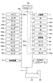
- the vehicle air conditioner 1 has a control device 50.
- the control device 50 is configured of a known microcomputer including a CPU, a ROM, a RAM, and the like, and peripheral circuits thereof.
- control device 50 performs various calculations and processes based on the air conditioning control program stored in the ROM, and controls the operation of various control target devices connected to the output side.
- the control target devices include the compressor 11, the first expansion valve 14a, the second expansion valve 14b, the first on-off valve 15a, the second on-off valve 15b, the outside air fan 16a, the blower 32, the heating side water pump 41, and the water heating heater 42. , A flow control valve 47, an engine pump EGp, and the like.
- control device 50 On the input side of the control device 50, various air conditioning sensor groups used for operation control by the vehicle air conditioner 1 are connected. And the detection signal of these air conditioning sensor groups is inputted into the control device 50 concerned.
- the air conditioning sensor group includes an inside air temperature sensor 51, an outside air temperature sensor 52, a solar radiation sensor 53, a first water temperature sensor 54a, a second water temperature sensor 54b, a first refrigerant temperature sensor 55a, and a second refrigerant temperature sensor. 55b, a third refrigerant temperature sensor 55c, a discharge pressure sensor 56a, an outdoor unit pressure sensor 56b, an evaporator temperature sensor 57, an air conditioning air temperature sensor 58, and the like.
- the inside air temperature sensor 51 is an inside air temperature detection unit that detects a vehicle room temperature (inside air temperature) Tr.
- the outside air temperature sensor 52 is an outside air temperature detection unit that detects the temperature outside the vehicle (outside air temperature) Tam.
- the solar radiation sensor 53 is a solar radiation amount detection unit that detects the solar radiation amount As emitted to the vehicle interior.
- the first water temperature sensor 54 a is a coolant temperature detection unit that detects the coolant temperature on the coolant inlet side of the radiator 12 in the heating side heat medium circuit 40.
- the second water temperature sensor 54 b is a coolant temperature detection unit that detects the coolant temperature on the coolant outlet side of the radiator 12 in the heating-side heat medium circuit 40.
- the first water temperature sensor 54a detects the temperature of the cooling water on the inlet side of the radiator 12, but as the first water temperature sensor 54a, one that detects the temperature of the cooling water flowing out of the heater core 43 is employed. It is also good.
- the first refrigerant temperature sensor 55a is a first refrigerant temperature detection unit that detects the discharge temperature Td1 of the refrigerant discharged from the compressor 11.
- the second refrigerant temperature sensor 55 b is a second refrigerant temperature detection unit that detects an outlet side discharge temperature Td 2 of the refrigerant flowing out of the radiator 12.
- the third refrigerant temperature sensor 55c is a third refrigerant temperature detection unit that detects the temperature (outdoor heat exchanger temperature) Td3 of the refrigerant flowing out of the outdoor heat exchanger 16.
- the discharge pressure sensor 56a is a discharge pressure detection unit that detects the high pressure side refrigerant pressure Pd of the refrigerant passage extending from the discharge port side of the compressor 11 to the inlet side of the first expansion valve 14a.
- the outdoor unit pressure sensor 56 b is an outdoor unit pressure detection unit that detects the pressure (outdoor unit refrigerant pressure) Ps of the refrigerant flowing out of the outdoor heat exchanger 16.
- the evaporator temperature sensor 57 is an evaporator temperature detection unit that detects a refrigerant evaporation temperature (evaporator temperature) Tefin in the indoor evaporator 18.
- the air conditioning air temperature sensor 58 is an air conditioning air temperature detection unit that detects the air temperature TAV blown into the vehicle compartment from the mixing space.
- an operation panel 60 is connected to the input side of the control device 50.
- the operation panel 60 is disposed in the vicinity of the dashboard in the front of the passenger compartment and has various operation switches. Therefore, operation signals from various operation switches are input to the control device 50.
- Various operation switches in the operation panel 60 include an auto switch, a cooling switch, an air volume setting switch, a temperature setting switch, a blowout mode switching switch, and the like.
- the auto switch is operated when setting or canceling the automatic control operation of the vehicle air conditioner 1.
- the cooling switch is operated when it is requested that the vehicle air conditioner 1 cool the vehicle interior.
- the air volume setting switch is operated when manually setting the air volume of the blower 32.
- the temperature setting switch is operated when setting a target temperature Tset in the vehicle compartment.
- the blowout mode switching switch is operated when manually setting the blowout mode in the vehicle air conditioner 1.
- a vehicle control device 70 is connected to the input side of the control device 50. As described above, in the hybrid vehicle, the vehicle control device 70 performs switching control between the EV travel mode and the HV travel mode. Therefore, a traveling mode signal indicating the traveling mode (that is, the HV traveling mode or the EV traveling mode) of the hybrid vehicle is input to control device 50.
- the control device 50 is integrally configured with a control unit that controls various control target devices connected to the output side, but controls the operation of each control target device.
- the configuration (hardware and software) constitutes a control unit that controls the operation of each control target device.
- the configuration for controlling the amount of heat generated by the refrigeration cycle device 10 constitutes a cycle heat amount control unit 50a.
- the cycle heat quantity control unit 50a controls the operation of the compressor 11, the first expansion valve 14a, the second expansion valve 14b, the first on-off valve 15a, the second on-off valve 15b, the outside air fan 16a, and the blower 32.
- produces with the water heating heater 42 among the control apparatuses 50 comprises the heater calorie
- the heater heat quantity control unit 50 b can be said to be configured to control the amount of power supplied to the water heating heater 42.
- the configuration for controlling the operation of the water heating heater 42, the engine pump EGp, and the flow rate adjustment valve 47 constitutes a cooling water flow rate adjustment unit 50c.
- the cooling water flow rate adjustment unit 50c is configured to adjust the flow rate balance between the cooling water flow rate passing through the engine EG and the cooling water flow rate passing through the heat source device (i.e., the water heating heater 42 and the radiator 12). it can.
- the vehicle air conditioner 1 can perform cooling, dehumidifying heating, and heating of the passenger compartment.
- the refrigeration cycle apparatus 10 in the vehicle air conditioner 1 switches the operation of the cooling mode, the dehumidifying heating mode, and the heating mode for air conditioning of the vehicle interior.
- Switching of each operation mode of the refrigeration cycle apparatus 10 is performed by executing an air conditioning control program.
- the air conditioning control program is executed when the automatic switch of the operation panel 60 is turned on and the automatic control is set.
- a target blowout temperature TAO which is a target temperature of the blowout air blown into the vehicle compartment, is calculated based on the following formula F1.
- TAO Kset ⁇ Tset ⁇ Kr ⁇ Tr ⁇ Kam ⁇ Tam ⁇ Ks ⁇ As + C (F1)
- Tset is a target temperature (set temperature in the vehicle compartment) set by the temperature setting switch
- Tr is an internal temperature detected by the internal air temperature sensor 51
- Tam is an external air temperature detected by the external air temperature sensor 52
- As I the amount of solar radiation detected by the solar radiation sensor 53.
- Kset, Kr, Kam, and Ks are control gains
- C is a correction constant.
- the operation mode is switched to the cooling mode when the target blowing temperature TAO is lower than the predetermined cooling reference temperature ⁇ .
- the operation mode is switched to the dehumidifying and heating mode when the target blowing temperature TAO is equal to or higher than the cooling reference temperature ⁇ .
- the operation mode is switched to the heating mode.
- the cooling mode is mainly performed when the outside air temperature is relatively high as in summer.
- the dehumidifying heating mode is mainly performed in spring or autumn.
- the heating mode is mainly performed during low winter temperatures.
- control device 50 closes the first on-off valve 15a and closes the second on-off valve 15b. Then, the control device 50 displaces the air mix door 34 so that the air passage on the heater core 43 side is fully closed and the bypass passage 35 side is fully open.
- the compressor 11 ( ⁇ radiator 12 ⁇ first expansion valve 14 a) ⁇ outdoor heat exchanger 16 ⁇ check valve 17
- a vapor compression type refrigeration cycle in which the refrigerant circulates in the order of the second expansion valve 14b ⁇ the indoor evaporator 18 ⁇ the evaporation pressure adjusting valve 19 ⁇ the accumulator 20 ⁇ the compressor 11 is configured.
- the controller 50 determines the refrigerant discharge capacity of the compressor 11 (that is, the control signal output to the electric motor of the compressor 11). Specifically, the operation of the compressor 11 is controlled such that the blown air blown out from the indoor evaporator 18 reaches the target evaporator temperature TEO.
- the target evaporator temperature TEO is determined based on the target blowout temperature TAO with reference to a control map stored in advance in the control device 50. In this control map, it is determined that the target evaporator temperature TEO decreases as the target outlet temperature TAO decreases. Furthermore, the target evaporator temperature TEO is determined in a range (specifically, 1 ° C. or higher) in which frost formation of the indoor evaporator 18 can be suppressed.
- control device 50 adjusts the throttle opening degree of the second expansion valve 14b so that the degree of subcooling of the refrigerant flowing into the second expansion valve 14b becomes the target degree of subcooling for cooling.
- the target degree of subcooling for cooling is determined based on the outdoor unit refrigerant pressure Ps and the outdoor heat exchanger temperature Td3 with reference to a control map stored in advance in the control device 50. In this control map, the target degree of subcooling for cooling is determined such that the coefficient of performance COPr of the cycle approaches the maximum value.
- a refrigeration cycle in which the outdoor heat exchanger 16 functions as a radiator and the indoor evaporator 18 functions as an evaporator is configured. Then, when the refrigerant evaporates in the indoor evaporator 18, the heat absorbed from the air is radiated to the outside air by the outdoor heat exchanger 16. Thereby, the air can be cooled. Therefore, in the cooling mode, cooling the vehicle interior can be performed by blowing out the air cooled by the indoor evaporator 18 into the vehicle interior.
- the refrigerant that has passed through the check valve 17 can be branched into a flow from the fifth three-way joint 13 e toward the second expansion valve 14 b and a flow toward the battery 25.
- a throttle mechanism (not shown) is disposed on the refrigerant path from the fifth three-way joint 13 e to the battery 25. Therefore, the low pressure refrigerant decompressed by the throttling mechanism is supplied around the battery 25. Thus, the heat generated in the battery 25 can be absorbed by the latent heat of vaporization of the low-pressure refrigerant, so the refrigeration cycle apparatus 10 in the cooling mode can cool the battery 25.
- control device 50 opens the first on-off valve 15a and the second on-off valve 15b. Then, the control device 50 displaces the air mix door 34 so that the air passage on the heater core 43 side is fully opened and the bypass passage 35 side is fully closed.
- the refrigerant circulates in the order of accumulator 20 ⁇ compressor 11, and the compressor 11 ⁇ radiator 12 ⁇ first on-off valve 15a ⁇ second expansion valve 14b ⁇ indoor evaporator 18 ⁇ evaporation pressure control valve 19 ⁇ accumulator 20 ⁇ compression
- a vapor compression refrigeration cycle in which the refrigerant circulates in the order of the machine 11 is configured. That is, a refrigeration cycle in which the outdoor heat exchanger 16 and the indoor evaporator 18 are connected in parallel to the refrigerant flow is configured.
- the controller 50 determines the refrigerant discharge capacity of the compressor 11 (that is, the control signal output to the electric motor of the compressor 11). Specifically, the operation of the compressor 11 is controlled such that the pressure of the refrigerant flowing into the radiator 12 becomes the target condensing pressure PDO.
- the target condensing pressure PDO is determined based on the target blowing temperature TAO with reference to a control map stored in advance in the control device 50. In this control map, it is determined that the target condensing pressure PDO increases with the increase of the target blowout temperature TAO.
- control device 50 refers to the control map stored in advance in the control device 50 based on the target blowout temperature TAO or the like, and the first expansion valve 14a and the first expansion valve 14a so that the coefficient of performance COPr of the cycle approaches the maximum value.
- the operation of the second expansion valve 14b is controlled. Specifically, the control device 50 decreases the throttle opening degree of the first expansion valve 14a as the target blow-out temperature TAO rises.
- the radiator 12 functions as a radiator and the refrigeration cycle in which the outdoor heat exchanger 16 and the indoor evaporator 18 function as evaporators is configured.
- the vehicle air conditioner 1 dissipates the heat absorbed when the refrigerant evaporates in the outdoor heat exchanger 16 and the indoor evaporator 18 to the blown air via the radiator 12 and the heating side heat medium circuit 40. Can. Thereby, the blowing air cooled and dehumidified by the indoor evaporator 18 can be reheated by the heater core 43.
- the blown air cooled and dehumidified by the indoor evaporator 18 is reheated by the heater core 43 through the radiator 12 and the heating side heat medium circuit 40 and blown out into the vehicle compartment.
- dehumidifying and heating of the vehicle interior can be performed. Since the refrigeration cycle apparatus 10 can reheat the dehumidified air, it functions as one of the heat source apparatuses in the dehumidifying and heating mode.
- control device 50 closes the first on-off valve 15a and opens the second on-off valve 15b. Then, the control device 50 displaces the air mix door 34 so that the air passage on the heater core 43 side is fully opened and the bypass passage 35 side is fully closed.
- the controller 50 determines the refrigerant discharge capacity of the compressor 11 (that is, the control signal output to the electric motor of the compressor 11). Specifically, the operation of the compressor 11 is controlled such that the pressure of the refrigerant flowing into the radiator 12 becomes the target condensing pressure PDO.
- the target condensing pressure PDO is determined based on the target blowing temperature TAO with reference to a control map stored in advance in the control device 50. In this control map, it is determined that the target condensing pressure PDO increases with the increase of the target blowout temperature TAO.
- control device 50 adjusts the throttle opening degree of the first expansion valve 14a such that the degree of subcooling of the refrigerant flowing into the first expansion valve 14a becomes the target degree of supercooling for heating.
- the target degree of subcooling for heating is determined with reference to a control map stored in advance in the control device 50, based on the high pressure side refrigerant pressure Pd detected by the discharge pressure sensor 56a. In this control map, a target degree of supercooling for heating is determined such that COPr approaches a maximum value.
- the radiator 12 functions as a radiator
- the outdoor heat exchanger 16 functions as an evaporator to constitute a refrigeration cycle. Then, when the refrigerant evaporates in the outdoor heat exchanger 16, the heat absorbed from the outside air can be released to the air by the heater core 43 through the radiator 12 and the heating side heat medium circuit 40.
- the refrigeration cycle device 10 can heat the blowing air, and functions as one of the heat source devices in the present disclosure. Therefore, in the heating mode, the vehicle air conditioner 1 can heat the vehicle interior by blowing the blown air heated by the heater core 43 into the vehicle interior which is the space to be heated.
- the air conditioning system 1 for a vehicle when heating the vehicle interior that is the space to be air conditioned, the heated air is heated by radiating heat with the heater core 43 that constitutes the heating side heat medium circuit 40. ing. Therefore, the operation of the heating side heat medium circuit 40 in the heating mode will be described.
- the hybrid vehicle equipped with the vehicle air conditioner 1 is configured to be capable of traveling in two traveling modes, the HV traveling mode and the EV traveling mode.
- the effective heat source in the heating mode also differs depending on the traveling mode of the hybrid vehicle.
- the control device 50 changes the flow path and the flow rate of the cooling water in the heating side heat medium circuit 40 based on the traveling mode signal output from the vehicle control device 70.
- the flow rate in the flow of the cooling water shown by the broken line arrow shall be smaller than the flow rate in the flow of the cooling water shown by the solid line arrow.
- the flow rate is such that the temperature of the cooling water on the side of the broken arrow does not excessively decrease.
- the control device 50 controls the operation of the engine pump EGp, the heating side water pump 41, and the flow rate adjustment valve 47.
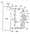
- the operation of the heating side water pump 41 or the like is performed so that the flow rate of the cooling water flowing through the path including the first connection flow path 45 is larger than the flow rate flowing through the path including the second connection flow path 46 Adjusted.
- the pumping capability of the heating side water pump 41 is controlled to be low. Further, the flow rate adjusting valve 47 is operated and controlled so as to connect the outlet / inlet on the side of the first connection portion 44 a with the outlet / inlet on the side of the third connection portion 44 c and close the outlet / inlet on the side of the second connection portion 44 b. Ru.
- the flow of the cooling water in the heating side heat medium circuit 40 is adjusted to the path including the first connection flow path 45 and the path including the second connection portion 44 b.
- the path including the first connection flow path 45 is: engine EG ⁇ engine pump EGp ⁇ first connection flow path 45 ⁇ first connection portion 44 a ⁇ flow control valve 47 ⁇ third connection portion 44 c ⁇ heater core 43 ⁇
- the path including the second connection flow path 46 is branched at the first connection portion 44a, and then the first connection portion 44a ⁇ second connection flow path 46 ⁇ heating side water pump 41 ⁇ water heating heater 42 ⁇ radiator This means a path that flows from the 12th to the third connection portion 44c and merges at the third connection portion 44c.
- the flow rate of the cooling water flowing in the path including the first connection flow path 45 corresponds to the first flow rate in the present disclosure.
- the flow rate of the cooling water which flows through the course containing the 2nd connection channel 46 is equivalent to the 2nd flow rate in this indication.
- the flow rate of the cooling water flowing from the first connection portion 44 a to the third connection portion 44 c via the second connection flow path 46 is the heat shock load of the heating side water pump 41, the water heating heater 42, and the radiator 12. Is adjusted to the minimum flow rate required to In other words, the flow rate of the cooling water flowing from the first connection portion 44 a to the third connection portion 44 c via the flow rate adjustment valve 47 occupies most of the cooling water circulating through the heating side heat medium circuit 40.
- the heating side heat medium circuit 40 mainly uses the exhaust heat of the engine EG as a heat source. Air can be heated.
- the heating in the time of HV driving mode can be implement
- heating of the cooling water by the water heating heater 42 and the radiator 12 disposed in the second connection flow path 46 is not necessarily required for heating the vehicle interior. .
- the vehicle air conditioner 1 heats the vehicle interior using exhaust heat of the engine EG even in a state in which the heating by the water heating heater 42 or the operation of the refrigeration cycle apparatus 10 in the heating mode is stopped. Can.
- the vehicle air conditioner 1 suppresses an increase in water flow resistance in the entire heating-side heat medium circuit 40 in the HV travel mode, and causes the coolant to flow more than necessary to the second connection flow path 46 in this case. It is possible to suppress the decrease in heating performance due to
- the cooling water warmed by the exhaust heat of the engine EG is transferred to the water heater 42 or the like via the second connection flow path 46.
- the radiator 12 is allowed to pass.
- the temperature of the cooling water in the water heating heater 42 or the radiator 12 does not excessively decrease. That is, even when the flow rate of the cooling water on the second connection flow path 46 side is increased, the heat shock load on the heater core 43 can be suppressed low, and the deterioration and damage of the heater core 43 can be suppressed.
- the flow rate of the flow of cooling water indicated by the broken line arrow is smaller than the flow rate of the flow of cooling water indicated by the solid line arrow.
- the flow rate is such that the temperature of the cooling water on the side of the broken arrow does not excessively decrease.
- the hybrid vehicle travels by the driving of the traveling electric motor by the power of the battery 25. That is, in the EV travel mode, it is difficult to utilize the exhaust heat of the engine EG as a heat source for heating the cooling water of the heating-side heat medium circuit 40.
- the heating-side heat medium circuit 40 of the vehicle air conditioner heat is generated by the water heating heater 42 or dissipated by the radiator 12 of the refrigeration cycle apparatus 10 when heating the vehicle interior in the EV travel mode. It is comprised so that the cooling water of the heating side heat carrier circuit 40 may be warmed using the heat which is.
- the control device 50 controls the operation of the engine pump EGp, the heating side water pump 41, and the flow rate adjustment valve 47,
- the flow rate of the cooling water flowing through the path including the second connection flow path 46 is adjusted to be larger than the flow rate flowing through the path including the first connection flow path 45.
- the pumping capacity of the heating side water pump 41 is controlled to be higher than that in the HV travel mode.
- the flow rate adjustment valve 47 is operated and controlled to connect the outlet / inlet on the side of the first connection portion 44 a with the outlet / inlet on the side of the second connection portion 44 b and close the outlet / inlet on the side of the third connection portion 44 c. .
- a path including the first connection flow path 45 and a path including the second connection flow path 46 are configured.
- the second connection portion 44 b ⁇ first connection flow path 45 ⁇ engine EG ⁇ engine It means a path that flows from the pump EGp ⁇ the first connection flow path 45 ⁇ the first connection portion 44a and merges at the first connection portion 44a.
- the path including the second connection flow path 46 in the EV travel mode is branched at the first connection portion 44a, and then the first connection portion 44a ⁇ second connection flow path 46 ⁇ heating side water pump 41 ⁇ water heating heater 42 ⁇ radiator 12 ⁇ third connection portion 44 c ⁇ heater core 43 ⁇ second connection portion 44 b ⁇ flow rate adjustment valve 47 ⁇ first connection portion 44 a means a path through which cooling water circulates.
- the heat of the cooling water heated by the operation of the water heating heater 42 and the high pressure refrigerant passing through the radiator 12 can be dissipated to the blowing air by the heater core 43. That is, the vehicle air conditioner 1 can use the water heating heater 42 or the radiator 12 of the refrigeration cycle apparatus 10 as a heat source device when heating the vehicle interior in the EV travel mode.
- the water heating heater 42 and the radiator 12 can be effectively utilized as a heating heat source, and the heating performance of the vehicle air conditioner 1 is enhanced. be able to.
- the vehicle air conditioner 1 suppresses an increase in water flow resistance in the entire heating-side heat medium circuit 40 in the EV travel mode, and allows the coolant to flow more than necessary to the first connection flow path 45 in this case. It is possible to suppress the decrease in heating performance due to
- the vehicle air conditioner 1 includes the heating side heat medium circuit 40 including the engine EG disposed as a drive source of the hybrid vehicle, the heater core 43, and the heating side water pump 41. Have.
- the vehicle air conditioner 1 heats the blowing air by radiating the heat of the cooling water to the blowing air blown by the blower 32 by the heater core 43 of the heating side heat medium circuit 40, thereby heating the passenger compartment. It can be heated.
- the engine EG is connected to the heater core 43 via the first connection flow path 45. Then, in the heating side heat medium circuit 40, the water heating heater 42 and the radiator 12 of the refrigeration cycle apparatus 10 are connected to the heater core 43 via the second connection flow path 46, and are parallel to the engine EG Is located in
- the cooling water flow rate adjustment unit 50c is configured such that the flow rate of the cooling water of the engine EG and the first connection flow path 45 is the flow rate of the cooling water on the second connection flow path 46 side.
- the operation of the heating side water pump 41 etc. is controlled so as to be more than that.
- the vehicle air conditioner 1 can perform heating of the vehicle interior by effectively utilizing the exhaust heat of the engine EG.
- the exhaust heat of the engine EG since the exhaust heat of the engine EG can be utilized, the necessity for the radiator 12 and the water heating heater 42 as a heating heat source is lower than that in the EV traveling mode.
- the air conditioning system 1 for the vehicle since the flow rate of the cooling water on the side of the second connection flow path 46 via the water heating heater 42 and the radiator 12 can be reduced, the air conditioning system 1 for the vehicle can The flow resistance as a whole can be suppressed to a low level, and a decrease in heating performance in the HV traveling mode can be suppressed.
- the flow rate of the cooling water on the second connection flow path 46 side can maintain the temperature of the cooling water inside the water heating heater 42 or the radiator 12, and is set to a small flow rate. Therefore, even when the flow rate of the cooling water on the second connection flow path 46 side is increased, the cooling water which has been completely cooled does not flow into the heater core 43.
- the heat shock load with respect to the heater core 43 can be reduced, and deterioration and damage of the heater core 43 accompanying the inflow of the low temperature cooling water can be suppressed.
- the heating side heat medium circuit 40 of the vehicle air conditioner 1 has a water heating heater 42, and heats the cooling water flowing through the second connection flow path 46. Can.
- the vehicle air conditioner 1 can heat the vehicle interior with the water heating heater 42 as a heat source device in the EV travel mode in which the exhaust heat of the engine EG can not be used.
- the heating-side heat medium circuit 40 according to the vehicle air conditioner 1 includes the radiator 12 of the refrigeration cycle apparatus 10, and the cooling water flowing in the second connection flow path 46 is not included in the refrigeration cycle apparatus 10.
- the heat of the high pressure refrigerant can be dissipated.
- the said vehicle air conditioner 1 can heat the vehicle interior in the EV driving mode which can not utilize the exhaust heat of engine EG, using the radiator 12 of the refrigerating-cycle apparatus 10 as a heat-source apparatus.
- the vehicle air conditioner 1 can perform not only heating of the passenger compartment but also cooling or dehumidifying of the passenger compartment.
- the vehicle air conditioner 1 which concerns on 2nd Embodiment is mounted in the hybrid vehicle similarly to 1st Embodiment.
- the hybrid vehicle in the second embodiment can switch between the HV traveling mode and the EV traveling mode under the control of the vehicle control device 70.
- the vehicle air conditioner 1 includes the refrigeration cycle apparatus 10, the indoor air conditioning unit 30, the heating side heat medium circuit 40, the control device 50, and the like, as in the first embodiment. ing.
- the vehicle air conditioner 1 according to the second embodiment has the same configuration as that of the first embodiment except for the specific configuration of the heating side heat medium circuit 40. Therefore, since the explanation about the refrigerating cycle device 10, the indoor air conditioning unit 30, the control device 50 and the like according to the second embodiment has already been explained, it will be omitted.
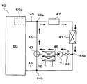
- the heat side heat medium circuit 40 is a heat that circulates the cooling water between the radiator 12 of the refrigeration cycle apparatus 10 or the components of the hybrid vehicle and the heater core 43. It is a medium circuit.
- the heating side heat medium circuit 40 includes the radiator 12 of the refrigeration cycle device 10, the engine EG, the heating side water pump 41, the water heating heater 42, and the heater core 43.
- an engine pump EGp is disposed on the outlet side of the cooling water passage in the engine EG. Also in the second embodiment, the outlet / inlet of the first connection portion 44a is connected to the outlet side of the engine pump EGp.
- the inlet side of the water heating heater 42 is connected to one of the outlet and inlet of the first connection portion 44a according to the second embodiment.
- the water heating heater 42 heats the coolant flowing through the coolant flow path.
- one of the outflow inlets in the flow control valve 47 is connected to one remaining outflow inlet.
- the inlet side of the heater core 43 is connected to the outlet side of the cooling water in the water heating heater 42.
- the heater core 43 is a heat exchanger for heating, and can exchange heat between the cooling water circulating through the heating-side heat medium circuit 40 and the air that has passed through the indoor evaporator 18 to heat the air.
- one outlet / inlet side of the third connection portion 44 c is connected to the outlet side of the heater core 43.
- the inlet side of the on-off valve 48 is connected to the other outlet / inlet of the third connection portion 44c.
- one outflow inlet side in the 2nd connection part 44b is connected to one remaining outflow side in the 3rd connection part 44c concerned.
- the on-off valve 48 is disposed to adjust the flow of the cooling water in the third connection portion 44c.
- the on-off valve 48 when the on-off valve 48 is closed, all the cooling water flowing into the third connection portion 44c flows toward the second connection portion 44b.
- the on-off valve 48 is opened, the cooling water having flowed into the third connection portion 44c is allowed to flow to the on-off valve 48 side.
- the on-off valve 48 constitutes one of the devices to be controlled by the cooling water flow rate adjustment unit 50c.
- the open / close state of the open / close valve 48 is switched according to the control signal from the controller 50. That is, the on-off valve 48 constitutes a part of the flow rate adjustment unit in the present disclosure.
- the suction port side of the heating side water pump 41 is connected to the outlet side of the on-off valve 48.
- the heating side water pump 41 according to the second embodiment is a water pump that sucks in and pumps the cooling water from the third connection portion 44c side.
- the outlet side of the heating side water pump 41 is connected to the coolant inlet side of the radiator 12 in the refrigeration cycle apparatus 10.
- the radiator 12 dissipates the heat of the high-pressure refrigerant compressed by the compressor 11 to the cooling water circulating through the heating-side heat medium circuit 40 at least in the heating mode.
- a flow control valve 47 is connected to the coolant outlet side of the radiator 12. As described above, one outlet / inlet of the flow rate adjustment valve 47 is connected to the first connection portion 44 a, and the other outlet / inlet is connected to the cooling water outlet side of the radiator 12.
- the second connection portion 44 b is connected to the remaining one flow inlet / outlet of the flow rate adjustment valve 47. Therefore, the flow rate adjustment valve 47 can adjust the flow rate of the cooling water passing through each outlet by operating the valve element disposed therein.
- the third connection portion 44c is connected to one outlet side of the second connection portion 44b, and the flow rate adjustment valve 47 is connected to the other one outlet side. ing.
- the inlet side of the cooling water passage in the engine EG is connected to the remaining one inlet / outlet side of the second connection portion 44b. Therefore, the heating-side heat medium circuit 40 according to the second embodiment can form a circulation circuit of cooling water through the engine EG, the heater core 43, and the like.
- the heating-side heat medium circuit 40 has the first connection flow path 45.
- the first connection channel 45 includes a cooling water channel connecting the outlet side of the engine EG to the first connection portion 44a, and a cooling water channel connecting the inlet side of the engine EG to the second connection portion 44b. There is.
- the first connection channel 45 corresponds to the first channel in the present disclosure.
- the heating side heat medium circuit 40 has a second connection flow path 46.
- the second connection flow path 46 means a cooling water flow path through which the radiator 12 and the like are disposed and which passes through the flow rate adjustment valve 47 among the cooling water flow paths connecting the first connection portion 44 a and the third connection portion 44 c. .
- the second connection channel 46 corresponds to the second channel in the present disclosure.
- the vehicle air conditioner 1 controls the heating-side heat medium circuit 40 according to the traveling mode in the heating mode, as in the first embodiment. This point will be described with reference to the drawings.
- the operation in the case of traveling in the HV traveling mode in the heating mode will be described with reference to FIG.
- the traveling mode signal indicating the HV traveling mode is output from the vehicle control device 70 in the heating mode
- the engine pump EGp the heating side water pump 41
- the flow rate adjustment valve 47 the operation of the on-off valve 48 is controlled.
- the pumping capacity of the engine pump EGp is adjusted to a predetermined state. Further, the operation of the heating side water pump 41 is stopped, and the on-off valve 48 is controlled to be in the closed state. At this time, the flow control valve 47 may also be controlled to shut off the flow between the first connection portion 44a and the second connection portion 44b.
- the flow of the cooling water in the heating side heat medium circuit 40 becomes a path including the first connection channel 45, and cools the second connection channel 46 in which the radiator 12 and the like are arranged. Water never passes.
- the path including the first connection flow path 45 is: engine EG ⁇ engine pump EGp ⁇ first connection flow path 45 ⁇ first connection portion 44 a ⁇ water heater 42 ⁇ heater core 43 ⁇ third It means a path through which the cooling water circulates in the order of the connecting portion 44c ⁇ the second connecting portion 44b ⁇ the first connecting flow path 45 ⁇ the engine EG.
- the cooling water flowing into the third connection portion 44c passes through the open / close valve 48, and the heating side water pump 41 and the radiator 12 are disposed. It does not flow into the second connection channel 46. That is, all of the cooling water flowing into the third connection portion 44c flows into the engine EG through the second connection portion 44b as it is.
- the vehicle air conditioner 1 can heat the vehicle interior by effectively utilizing the exhaust heat of the engine EG. Further, in the HV traveling mode, the cooling water does not flow to the second connection flow path 46 in which the radiator 12 and the heating-side water pump 41 are disposed, so the air conditioning system 1 for vehicle is heated in the HV traveling mode. It is possible to suppress an increase in water flow resistance in the entire side heat medium circuit 40, and to suppress a decrease in heating performance due to the coolant flowing more than necessary to the second connection flow path 46 in this case.
- the operation of the heating side heat medium circuit 40 according to the second embodiment when traveling in the EV travel mode in the heating mode will be described with reference to FIG.
- the traveling mode signal indicating the EV traveling mode is output from the vehicle control device 70 in the heating mode
- the engine pump EGp when the traveling mode signal indicating the EV traveling mode is output from the vehicle control device 70 in the heating mode, the engine pump EGp, the heating side water pump 41, the flow rate adjustment valve 47, The operation of the on-off valve 48 is controlled.
- the pumping capacity of the heating-side water pump 41 is adjusted to a predetermined state, and the on-off valve 48 is controlled to be in an open state.
- the flow rate adjustment valve 47 is controlled such that the outlet / inlet on the side of the first connection portion 44 a and the outlet / inlet on the side of the third connection portion 44 c are connected and the outlet / inlet on the side of the second connection portion 44 b is closed. Furthermore, the operation of the engine pump EGp is stopped.
- the flow of the cooling water in the heating side heat medium circuit 40 becomes a path including the second connection channel 46 in which the radiator 12 and the like are arranged, and the first connection channel 45 and the engine Cooling water never passes through the EG.
- the path including the second connection flow path 46 is the first connection portion 44a ⁇ the water heater 42 ⁇ the heater core 43 ⁇ the third connection portion 44c ⁇ the second connection flow path 46 ⁇ the on-off valve 48
- the heat of the cooling water heated by the operation of the water heating heater 42 and the high pressure refrigerant passing through the radiator 12 can be dissipated to the blowing air by the heater core 43. That is, the vehicle air conditioner 1 can use the water heating heater 42 or the radiator 12 of the refrigeration cycle apparatus 10 as a heat source device when heating the vehicle interior in the EV travel mode.
- the cooling water can be circulated on the second connection flow path 46 side, the water heating heater 42 and the radiator 12 can be effectively utilized as a heating heat source, and the heating performance of the air conditioner 1 for a vehicle can be obtained. It can be enhanced.
- the vehicle air conditioner 1 suppresses the increase in water flow resistance in the entire heating-side heat medium circuit 40 in the EV travel mode, and the heating performance by flowing the cooling water to the first connection flow path 45 in this case. Can be controlled.
- the same advantages as those of the first embodiment can be obtained from the configuration and operation common to those of the first embodiment. .
- the engine EG when traveling in the heating mode and in the HV traveling mode, the engine EG does not flow the cooling water into the second connection flow path 46 side.
- the cooling water is circulated through.
- the vehicle air conditioner 1 can perform heating of the vehicle interior in the HV traveling mode by making the most of exhaust heat of the engine EG. Then, the cooling water does not flow into the second connection flow channel 46 side.
- the flow resistance at the time of passing through the radiator 12 and the like does not act on the flow of the cooling water in the heating side heat medium circuit 40 in this case. That is, the said vehicle air conditioner 1 can suppress the fall of the heating performance by flowing a cooling water to the 2nd connection flow path 46 side in this case.
- the vehicle air conditioner 1 when traveling in the EV travel mode in the heating mode, causes the cooling water to flow into the first connection flow path 45 side, and causes the second connection flow without passing through the engine EG. Cooling water can be circulated on the side of the passage 46.
- the said vehicle air conditioner 1 can heat the vehicle interior in the electric vehicle drive mode by fully utilizing the heat of heat-source apparatuses, such as the radiator 12 and the water heating heater 42 grade
- the flow resistance of the water passing through the engine EG does not act on the flow of the cooling water in the heating side heat medium circuit 40 in this case. That is, the said vehicle air conditioner 1 can suppress the fall of the heating performance by flowing a cooling water to the 1st connection flow path 45 side in this case.
- the vehicle air conditioner 1 is configured to be able to execute not only the heating operation but also the cooling operation and the dehumidifying heating operation, but the present invention is not limited to this aspect. It is needless to say that the present disclosure may be configured as a vehicle heating device dedicated to heating, as long as at least heating is possible.
- the flow rate of the cooling water in the heating side heat medium circuit 40 is adjusted according to the switching of the traveling mode in the heating mode, but in the embodiment Absent.
- the flow rate of cooling water in the heating side heat medium circuit 40 even in the case of an operation mode in which the blowing air is heated via the cooling water which is the heat medium, the flow rate of cooling water is adjusted according good.
- the present invention may be applied to the case of heating the dehumidified blast air.
- only the radiator 12 of the refrigeration cycle apparatus 10 may be disposed as a heat source apparatus, or only the water heating heater 42 may be disposed as a heat source apparatus.
- the configuration may be
- the heat source device in the present disclosure it is sufficient to heat the heat medium circulating in the heat medium circuit, and various devices different from the radiator 12 and the water heater 42 of the refrigeration cycle device 10 may be applied. it can.
- the arrangement of the heat source devices (for example, the radiator 12 and the water heater 42) and the like in the heat medium circuit is not limited to the arrangement shown in FIGS.
- the arrangement of each component in the heat medium circuit is a route for circulating the heater core via the power unit in the mode based on the operation of the power unit as in the HV driving mode, and the power mode as in the EV driving mode In the mode which does not require the operation of the device, the heater core can be appropriately changed as long as it is configured to circulate the heater core through the heat source device.
- the heating side heat medium circuit 40 it is also possible to dispose a heat source device such as the radiator 12 or the water heating heater 42 on the downstream side of the heater core 43 with respect to the cooling water flow.
- the flow control part concerning this indication was considered as composition including flow control valve 47 which consists of three-way valves, it is not limited to this composition.
- the flow rate adjustment valve 47 in the above-described embodiment can be configured by a plurality of valves (for example, check valves and on-off valves).
Landscapes
- Engineering & Computer Science (AREA)
- Mechanical Engineering (AREA)
- Physics & Mathematics (AREA)
- Thermal Sciences (AREA)
- Chemical & Material Sciences (AREA)
- Combustion & Propulsion (AREA)
- Air-Conditioning For Vehicles (AREA)
Priority Applications (3)
| Application Number | Priority Date | Filing Date | Title |
|---|---|---|---|
| CN201880079949.1A CN111491815B (zh) | 2017-12-13 | 2018-11-06 | 车辆用制热装置 |
| DE112018006384.4T DE112018006384T5 (de) | 2017-12-13 | 2018-11-06 | Fahrzeugheizvorrichtung |
| US16/897,340 US11560039B2 (en) | 2017-12-13 | 2020-06-10 | Vehicular heater |
Applications Claiming Priority (2)
| Application Number | Priority Date | Filing Date | Title |
|---|---|---|---|
| JP2017238511A JP6874664B2 (ja) | 2017-12-13 | 2017-12-13 | 車両用暖房装置 |
| JP2017-238511 | 2017-12-13 |
Related Child Applications (1)
| Application Number | Title | Priority Date | Filing Date |
|---|---|---|---|
| US16/897,340 Continuation US11560039B2 (en) | 2017-12-13 | 2020-06-10 | Vehicular heater |
Publications (1)
| Publication Number | Publication Date |
|---|---|
| WO2019116781A1 true WO2019116781A1 (ja) | 2019-06-20 |
Family
ID=66820198
Family Applications (1)
| Application Number | Title | Priority Date | Filing Date |
|---|---|---|---|
| PCT/JP2018/041080 Ceased WO2019116781A1 (ja) | 2017-12-13 | 2018-11-06 | 車両用暖房装置 |
Country Status (5)
| Country | Link |
|---|---|
| US (1) | US11560039B2 (enExample) |
| JP (1) | JP6874664B2 (enExample) |
| CN (1) | CN111491815B (enExample) |
| DE (1) | DE112018006384T5 (enExample) |
| WO (1) | WO2019116781A1 (enExample) |
Cited By (1)
| Publication number | Priority date | Publication date | Assignee | Title |
|---|---|---|---|---|
| CN115891558A (zh) * | 2021-09-30 | 2023-04-04 | 三花控股集团有限公司 | 热管理系统及其控制方法 |
Families Citing this family (6)
| Publication number | Priority date | Publication date | Assignee | Title |
|---|---|---|---|---|
| JP6676682B2 (ja) * | 2018-03-09 | 2020-04-08 | マレリ株式会社 | 空調装置 |
| KR102575995B1 (ko) * | 2018-10-04 | 2023-09-08 | 한온시스템 주식회사 | 열관리 시스템 |
| JP7371542B2 (ja) * | 2020-03-18 | 2023-10-31 | トヨタ自動車株式会社 | ハイブリッド車両 |
| JP2022052822A (ja) | 2020-09-24 | 2022-04-05 | トヨタ自動車株式会社 | 車両用空調装置 |
| JP7182657B2 (ja) * | 2021-04-28 | 2022-12-02 | 本田技研工業株式会社 | 車両 |
| US12344069B2 (en) | 2021-08-06 | 2025-07-01 | Robert Bosch Gmbh | Thermal management system for a vehicle |
Citations (6)
| Publication number | Priority date | Publication date | Assignee | Title |
|---|---|---|---|---|
| JPS5479336U (enExample) * | 1977-11-15 | 1979-06-05 | ||
| JP2001260640A (ja) * | 2000-03-21 | 2001-09-26 | Calsonic Kansei Corp | 車両用暖房装置 |
| JP2002364362A (ja) * | 2001-06-08 | 2002-12-18 | Toyota Motor Corp | エンジン冷却装置 |
| JP2008230422A (ja) * | 2007-03-20 | 2008-10-02 | Toyota Motor Corp | 車両の冷却装置 |
| JP2012176658A (ja) * | 2011-02-25 | 2012-09-13 | Sanden Corp | 車両用空気調和装置 |
| WO2017159455A1 (ja) * | 2016-03-14 | 2017-09-21 | カルソニックカンセイ株式会社 | 空調装置 |
Family Cites Families (10)
| Publication number | Priority date | Publication date | Assignee | Title |
|---|---|---|---|---|
| DE10239876A1 (de) | 2002-08-29 | 2004-03-04 | Bayerische Motoren Werke Ag | Klimaanlage für ein Fahrzeug mit einem flüssigkeitsgekühlten Antriebsaggregat, insbesondere Brennkraftmaschine |
| US9849753B2 (en) | 2008-05-16 | 2017-12-26 | GM Global Technology Operations LLC | Heating system for an automotive vehicle |
| DE112012000522B4 (de) | 2011-01-21 | 2020-12-17 | Sanden Holdings Corporation | Fahrzeugklimatisierungseinrichtung |
| US9925877B2 (en) | 2011-01-21 | 2018-03-27 | Sanden Holdings Corporation | Vehicle air conditioning apparatus |
| JP2014036530A (ja) * | 2012-08-09 | 2014-02-24 | Calsonic Kansei Corp | 冷媒流量制御システム及び空調装置 |
| DE112014001746T5 (de) * | 2013-03-29 | 2015-12-24 | Honda Motor Co., Ltd. | Fahrzeug-Klimaanlage |
| JP6271222B2 (ja) * | 2013-11-12 | 2018-01-31 | カルソニックカンセイ株式会社 | 車両用冷媒循環装置、及び車両用空調装置 |
| DE102014113526A1 (de) | 2014-09-19 | 2016-03-24 | Halla Visteon Climate Control Corporation | Klimatisierungssystem für ein Kraftfahrzeug |
| KR101703604B1 (ko) | 2015-10-19 | 2017-02-07 | 현대자동차 주식회사 | 차량용 배터리 냉각 시스템 |
| JP6399060B2 (ja) * | 2015-10-29 | 2018-10-03 | 株式会社デンソー | ヒートポンプシステム |
-
2017
- 2017-12-13 JP JP2017238511A patent/JP6874664B2/ja not_active Expired - Fee Related
-
2018
- 2018-11-06 DE DE112018006384.4T patent/DE112018006384T5/de active Pending
- 2018-11-06 WO PCT/JP2018/041080 patent/WO2019116781A1/ja not_active Ceased
- 2018-11-06 CN CN201880079949.1A patent/CN111491815B/zh active Active
-
2020
- 2020-06-10 US US16/897,340 patent/US11560039B2/en active Active
Patent Citations (6)
| Publication number | Priority date | Publication date | Assignee | Title |
|---|---|---|---|---|
| JPS5479336U (enExample) * | 1977-11-15 | 1979-06-05 | ||
| JP2001260640A (ja) * | 2000-03-21 | 2001-09-26 | Calsonic Kansei Corp | 車両用暖房装置 |
| JP2002364362A (ja) * | 2001-06-08 | 2002-12-18 | Toyota Motor Corp | エンジン冷却装置 |
| JP2008230422A (ja) * | 2007-03-20 | 2008-10-02 | Toyota Motor Corp | 車両の冷却装置 |
| JP2012176658A (ja) * | 2011-02-25 | 2012-09-13 | Sanden Corp | 車両用空気調和装置 |
| WO2017159455A1 (ja) * | 2016-03-14 | 2017-09-21 | カルソニックカンセイ株式会社 | 空調装置 |
Cited By (1)
| Publication number | Priority date | Publication date | Assignee | Title |
|---|---|---|---|---|
| CN115891558A (zh) * | 2021-09-30 | 2023-04-04 | 三花控股集团有限公司 | 热管理系统及其控制方法 |
Also Published As
| Publication number | Publication date |
|---|---|
| CN111491815A (zh) | 2020-08-04 |
| DE112018006384T5 (de) | 2020-08-27 |
| CN111491815B (zh) | 2023-07-07 |
| US11560039B2 (en) | 2023-01-24 |
| JP2019104393A (ja) | 2019-06-27 |
| JP6874664B2 (ja) | 2021-05-19 |
| US20200298665A1 (en) | 2020-09-24 |
Similar Documents
| Publication | Publication Date | Title |
|---|---|---|
| US11525611B2 (en) | Refrigeration cycle device for vehicle | |
| US12257880B2 (en) | Refrigeration cycle device | |
| US10889163B2 (en) | Heat pump system | |
| JP6794964B2 (ja) | 冷凍サイクル装置 | |
| US9786964B2 (en) | Refrigeration cycle device for auxiliary heating or cooling | |
| US20190111756A1 (en) | Refrigeration cycle device | |
| CN112638674B (zh) | 制冷循环装置 | |
| CN110997369B (zh) | 制冷循环装置 | |
| WO2019116781A1 (ja) | 車両用暖房装置 | |
| JP6075058B2 (ja) | 冷凍サイクル装置 | |
| JP2020142789A (ja) | 熱管理システム | |
| WO2022181110A1 (ja) | 空調装置 | |
| CN113423596A (zh) | 制冷循环装置 | |
| JP2020040429A (ja) | 冷凍サイクル装置 | |
| JP6922856B2 (ja) | 冷凍サイクル装置 | |
| WO2021220661A1 (ja) | 車両用空調装置 | |
| WO2019031221A1 (ja) | 冷凍サイクル装置 | |
| JP6881383B2 (ja) | 電池冷却装置 | |
| JP7768378B2 (ja) | ヒートポンプサイクル装置 | |
| WO2025234209A1 (ja) | 冷凍サイクル装置 | |
| WO2025220367A1 (ja) | 冷凍サイクル装置 | |
| WO2024101061A1 (ja) | ヒートポンプサイクル装置 | |
| JP2025090870A (ja) | ヒートポンプサイクル装置 |
Legal Events
| Date | Code | Title | Description |
|---|---|---|---|
| 121 | Ep: the epo has been informed by wipo that ep was designated in this application |
Ref document number: 18887602 Country of ref document: EP Kind code of ref document: A1 |
|
| 122 | Ep: pct application non-entry in european phase |
Ref document number: 18887602 Country of ref document: EP Kind code of ref document: A1 |