WO2019107458A1 - Laminated glass - Google Patents
Laminated glass Download PDFInfo
- Publication number
- WO2019107458A1 WO2019107458A1 PCT/JP2018/043882 JP2018043882W WO2019107458A1 WO 2019107458 A1 WO2019107458 A1 WO 2019107458A1 JP 2018043882 W JP2018043882 W JP 2018043882W WO 2019107458 A1 WO2019107458 A1 WO 2019107458A1
- Authority
- WO
- WIPO (PCT)
- Prior art keywords
- heating wire
- glass plate
- layer
- laminated glass
- bus bars
- Prior art date
Links
Images


Classifications
-
- B—PERFORMING OPERATIONS; TRANSPORTING
- B60—VEHICLES IN GENERAL
- B60J—WINDOWS, WINDSCREENS, NON-FIXED ROOFS, DOORS, OR SIMILAR DEVICES FOR VEHICLES; REMOVABLE EXTERNAL PROTECTIVE COVERINGS SPECIALLY ADAPTED FOR VEHICLES
- B60J1/00—Windows; Windscreens; Accessories therefor
-
- B—PERFORMING OPERATIONS; TRANSPORTING
- B60—VEHICLES IN GENERAL
- B60S—SERVICING, CLEANING, REPAIRING, SUPPORTING, LIFTING, OR MANOEUVRING OF VEHICLES, NOT OTHERWISE PROVIDED FOR
- B60S1/00—Cleaning of vehicles
- B60S1/02—Cleaning windscreens, windows or optical devices
-
- H—ELECTRICITY
- H05—ELECTRIC TECHNIQUES NOT OTHERWISE PROVIDED FOR
- H05B—ELECTRIC HEATING; ELECTRIC LIGHT SOURCES NOT OTHERWISE PROVIDED FOR; CIRCUIT ARRANGEMENTS FOR ELECTRIC LIGHT SOURCES, IN GENERAL
- H05B3/00—Ohmic-resistance heating
- H05B3/20—Heating elements having extended surface area substantially in a two-dimensional plane, e.g. plate-heater
- H05B3/22—Heating elements having extended surface area substantially in a two-dimensional plane, e.g. plate-heater non-flexible
- H05B3/26—Heating elements having extended surface area substantially in a two-dimensional plane, e.g. plate-heater non-flexible heating conductor mounted on insulating base
-
- H—ELECTRICITY
- H05—ELECTRIC TECHNIQUES NOT OTHERWISE PROVIDED FOR
- H05B—ELECTRIC HEATING; ELECTRIC LIGHT SOURCES NOT OTHERWISE PROVIDED FOR; CIRCUIT ARRANGEMENTS FOR ELECTRIC LIGHT SOURCES, IN GENERAL
- H05B3/00—Ohmic-resistance heating
- H05B3/84—Heating arrangements specially adapted for transparent or reflecting areas, e.g. for demisting or de-icing windows, mirrors or vehicle windshields
- H05B3/86—Heating arrangements specially adapted for transparent or reflecting areas, e.g. for demisting or de-icing windows, mirrors or vehicle windshields the heating conductors being embedded in the transparent or reflecting material
Definitions
- the present invention relates to laminated glass.
- Patent Document 1 discloses that a bus bar and a heating wire are disposed inside a windshield and heat generation removes fogging.
- the windshield is formed of laminated glass in which a bus bar and the like are disposed together with an adhesive layer between two glass plates. And when producing this laminated glass, after arrange
- the above-mentioned functional layer can be formed so that the outer peripheral edge may be in agreement with the outer peripheral edge of a glass plate, and since it does not produce the above-mentioned level difference if it does in this way, generation of bubbles is prevented. Can. However, in this case, since the outer peripheral edge of the functional layer is exposed from between the glass plates, there is a possibility that water may infiltrate between the glass plates from here. As a result, when the laminated glass is swollen, there is a risk of losing the original function of the laminated glass. There are also the following problems.
- each glass plate may be formed in a circular arc shape in cross section, if the outer periphery of the functional layer matches the outer periphery of the glass plate, the adhesive layers may not adhere to each other. However, this may cause wrinkles in the adhesive layer or the functional layer. Therefore, the entry of water can be prevented by positioning the position of the outer peripheral edge of the adhesive layer closer to the center than the position of the outer glass position (for example, about several mm to about 30 mm). However, when the position of the outer peripheral edge of the adhesive layer is located inside the outer peripheral edge of the glass plate as described above, the above-mentioned bubbles may occur.
- the present invention has been made to solve the above problems, and provides a laminated glass in which a functional layer is disposed between two glass plates, which can improve the quality of appearance. With the goal.
- Item 1 An outer glass plate having a first side and a second side opposite to the first side, An inner glass plate disposed opposite to the outer glass plate and having substantially the same shape as the outer glass plate; An interlayer disposed between the outer glass plate and the inner glass plate; A shielding layer formed on the surface of the outer glass plate; Equipped with The interlayer is Adhesive layer, A functional layer supported by the adhesive layer; Equipped with At least a part of the outer peripheral edge of the functional layer has an inner portion located inside the outer peripheral edge of the adhesive layer, The laminated glass, wherein the shielding layer is disposed to cover at least an inner portion of the functional layer and an outer peripheral edge of the adhesive layer.
- Item 2 The laminated glass of Item 1, wherein the shielding layer is located on the surface on the intermediate film side of the outer glass plate.
- Item 3 The laminated glass according to Item 2, further comprising a second shielding layer provided on the surface of the inner glass plate opposite to the intermediate film.
- Item 4 The laminated glass according to any one of Items 1 to 3, wherein the shielding layer is formed over the entire periphery of the outer peripheral edge of the outer glass plate.
- Item 5 The laminated glass according to any one of Items 1 to 4, wherein the shielding layer is disposed between the outer glass plate and the intermediate film.
- Item 6 The laminated glass according to any one of Items 1 to 5, wherein the thickness of the functional layer is 5 to 200 ⁇ m.
- the functional layer is A first bus bar, at least a portion of which extends along the end on the first side; A second bus bar, at least a portion of which extends along an end on the second side; A plurality of heating wires arranged to connect the first bus bar and the second bus bar; Equipped with A part of the outer peripheral edge of the first bus bar and the second bus bar constitutes the inner portion, 7.
- the functional layer further includes a support layer that supports both the bus bars and the heating wire, Item 8.
- Item 9 The laminated glass according to item 7 or 8, wherein both bus bars are formed by laminating a plurality of metal layers.
- Item 10 The laminated glass according to any one of Items 7 to 9, wherein the pitch of the heating wire is 1.25 to 4 mm.
- Item 11 The laminated glass according to any one of Items 7 to 10, wherein the calorific value of the heating wire is 2.0 W / m or less.
- Item 12 The laminated glass according to any one of Items 7 to 11, wherein the thickness of the heating wire is 30 ⁇ m or less.
- Item 13 The laminated glass according to any one of Items 7 to 12, wherein the width of the surface on the adhesive layer side in the heating wire is 1 to 30 ⁇ m.
- Item 14 The voltage applied to both the bus bars is less than 20 V, The width of the surface on the side of the adhesive layer in the heating wire has a length equal to or greater than the thickness of the heating wire, Item 14.
- Item 15 The voltage applied to the both bus bars is 20 to 50 V, The width of the surface on the side of the adhesive layer in the heating wire has a length equal to or greater than the thickness of the heating wire, Item 14.
- the quality of appearance can be improved.
- FIG. 1 It is a front view of one embodiment of a laminated glass concerning the present invention. It is the sectional view on the AA line of FIG. It is a figure which shows an example of a heating wire. It is a side view of a furnace through which a forming die passes. It is a top view of a forming die. It is the photograph which image
- FIG. 18 is a table showing the specifications of heating wires according to Reference Examples 17 to 27.
- FIG. It is a front view which shows the other example of the laminated glass of FIG. It is a front view which shows the other example of the laminated glass of FIG.
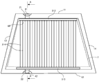
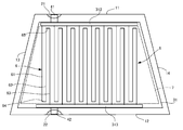
- FIG. 1 is a plan view of a windshield according to the present embodiment
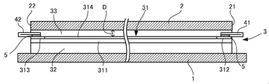
- FIG. 2 is a cross-sectional view of FIG.
- the windshield according to the present embodiment includes an outer glass plate 1, an inner glass plate 2, and an intermediate layer 3 disposed between the glass plates 1 and 2. Further, notches 21 and 22 are respectively formed at the upper end and the lower end of the inner glass plate 2, and the connecting members 41 and 42 extending from the intermediate layer 3 are exposed at the respective notches 21 and 22. doing. Each member will be described below.
- Each of the glass plates 1 and 2 is formed in a rectangular shape in which the lower side 12 is longer than the upper side 11. That is, it is formed in a trapezoidal shape surrounded by the upper side 11, the lower side 12, and both sides (left side 13 and right side 14). And as above-mentioned, the circular-arc-shaped notch part is formed in the upper end part and lower end part of the inner side glass plate 2, respectively.
- the notch formed in the upper end of the inner glass plate 2 will be referred to as a first notch 21 and the notch formed in the lower end will be referred to as a second notch 22.
- each glass plate 1 and 2 a well-known glass plate can be used and it can also form with heat ray absorption glass, general clear glass, green glass, or UV green glass.
- these glass plates 1 and 2 need to realize visible light transmittance in accordance with the safety standard of the country where the automobile is used.
- the required solar radiation absorptivity can be secured by the outer glass plate 1, and the visible light transmittance can be adjusted by the inner glass plate 2 so that the safety standard is satisfied.
- a composition of clear glass, heat ray absorption glass, and soda lime type glass is shown.
- the composition of the heat-absorbing glass for example, based on the composition of the clear glass, the proportion of the total iron oxide in terms of Fe 2 O 3 (T-Fe 2 O 3) and 0.4 to 1.3 wt%, CeO
- the ratio of 2 is 0-2% by mass
- the ratio of TiO 2 is 0-0.5% by mass
- the framework component of the glass (mainly SiO 2 or Al 2 O 3 ) is T-Fe 2 O 3
- CeO The composition can be reduced by the increase of 2 and TiO 2 .
- each of the glass plates 1 and 2 is formed in a rectangular shape, but the ratio of the lengths of the upper side 11 and the lower side 12 may be, for example, 1: 1.04 to 1: 1.5. it can.
- the lower side can be 1250 to 1800 mm.
- the upper side can be 1195 mm and the lower side can be 1435 mm.
- the ratio described above is a ratio in a two-dimensional plane when the windshield is projected from the front.
- the upper side 11 is applicable also to a long windshield.
- the lower side can be 350 to 450 mm.
- the upper side can be 500 mm and the lower side can be 425 mm.
- the thickness of the laminated glass according to the present embodiment is not particularly limited, but from the viewpoint of weight reduction, the total thickness of the outer glass plate 1 and the inner glass plate 2 is preferably 2.4 to 4.6 mm. It is more preferable to set the diameter to 2.6 to 3.4 mm, and it is particularly preferable to set the diameter to 2.7 to 3.2 mm.
- the thickness of each glass plate is not particularly limited,
- the thickness of the outer side glass plate 1 and the inner side glass plate 2 can be determined as follows.
- the outer glass plate 1 is mainly required to be resistant to external obstacles and impact resistance. For example, when this laminated glass is used as a windshield of an automobile, the impact resistance to flying objects such as pebbles is excellent. is necessary. On the other hand, the larger the thickness is, the more the weight increases. From this viewpoint, the thickness of the outer glass plate 1 is preferably 1.0 to 3.0 mm, and more preferably 1.6 to 2.3 mm. Which thickness is adopted can be determined according to the application of the glass.
- the thickness of the inner side glass plate 2 can be made equivalent to the outer side glass plate 1, for example, thickness can be made smaller than the outer side glass plate 1 for weight reduction of laminated glass. Specifically, in consideration of the strength of the glass, it is preferably 0.6 to 2.0 mm, more preferably 0.8 to 1.8 mm, and preferably 0.8 to 1.6 mm. Particularly preferred. More preferably, it is 0.8 to 1.3 mm. Also about the inner side glass plate 2, it can be determined according to the use of glass which thickness is employ
- middle layer 3 mentioned later is arrange
- the shape of the outer side glass plate 1 which concerns on this embodiment, and the inner side glass plate 2 may be curved shape.
- the dust amount is an amount indicating bending of the glass plate, and when the straight line L connecting the center of the upper side and the center of the lower side of the glass plate is set, the largest of the distances between the straight line L and the glass plate Define as a dust amount D.
- the amount of debris is preferably less than 30 mm, more preferably less than 25 mm, and particularly preferably less than 20 mm.
- the measurement position there are two positions on the center line extending in the vertical direction at the center in the horizontal direction of the glass plate.
- the measuring device is not particularly limited, but for example, a thickness gauge such as SM-112 manufactured by Teclock Co., Ltd. can be used.
- SM-112 manufactured by Teclock Co., Ltd.
- the curved surface of the glass plate is placed on a flat surface, and the edge portion of the glass plate is held and measured by the thickness gauge.
- the intermediate layer 3 is formed of three layers including a heat generating layer 31 and a pair of adhesive layers 32 and 33 having the same shape as the glass plates 1 and 2 sandwiching the heat generating layer 31.
- the adhesive layer disposed on the outer glass plate 1 side is referred to as a first adhesive layer 32
- the adhesive layer disposed on the inner glass plate 2 side is referred to as a second adhesive layer 33.
- the heat generating layer 31 includes a plurality of heating wires 314 as described later, thereby removing snow, ice and fog generated on the surface of the windshield.
- the heat generated by the heating wire 314 heats the adhesive layers 32, 33 and the like around it, which may cause flicker when looking out of the vehicle through the windshield.
- the heating wire 314 is required to have a calorific value capable of performing ice melting and the like, and prevention of flickering is also required. Therefore, in the present embodiment, as described later, the heating of the heating wire 314 is generated.
- the dimensions, such as amount, line width, pitch, etc., are set.
- the calorific value can be calculated by the following equation (1).
- the relationship between the resistance of the heating wire 314 and the length and cross-sectional area of the heating wire 314 is as shown in Formula (2).
- R ((L / A) (2)
- W power
- E voltage
- I current
- R resistance
- L length
- A cross-sectional area
- ⁇ electrical resistivity
- the resistance R is increased, the length L of the heating wire 314 is increased, and the cross-sectional area A of the heating wire 314 is decreased.
- a certain amount of calorific value is required for ice melting and the like. Therefore, when the calorific value of each heating wire 314 decreases, in order to maintain the calorific value of the whole windshield, it is necessary to increase the number of the heating wires 314.
- middle layer 3 is demonstrated hereafter, considering the above point.
- the heat generating layer 31 includes a sheet-like base (supporting layer) 311, and a first bus bar 312, a second bus bar 313, and a plurality of heating wires 314 disposed on the base 311.
- the plurality of heating wires 314 are connected in parallel so that both bus bars 312 and 313 serve as electrodes.
- the substrate 311 can be formed in a rectangular shape so as to correspond to the glass plates 1 and 2 and the adhesive layers 32 and 33, but may not necessarily have the same shape as the adhesive layers 32 and 33.
- the shape may be smaller than 1 and 2 (in this case, for example, in the periphery of the substrate 311, the portion inside the peripheral portion of the glass plate corresponds to the inner portion of the present invention).
- the length between the two notches 21 and 22 can be made shorter in the vertical direction so as not to interfere with the notches 21 and 22 of the inner glass plate 2.
- the length in the left-right direction of the base material 311 can also be shorter than the width of both the glass plates 1 and 2.
- the first bus bar 312 is formed to extend along the upper side of the base 311.
- the second bus bar 313 is formed to extend along the lower side of the base 311 but is formed to be longer than the first bus bar 312.
- each of the bus bars 312 and 313 is not provided with the notches 21 and 22 so as not to be exposed from the notches 21 and 22 described above when the intermediate layer 3 is sandwiched between the two glass plates 1 and 2. It is placed inside.
- the upper and lower widths of the bus bars 312 and 313 are preferably, for example, 5 to 50 mm, and more preferably 10 to 30 mm.
- the width of the bus bars 312 and 313 is smaller than 5 mm, the amount of heat generation in the bus bars increases, and the amount of heat generation of the heating wire 314 decreases, and a desired amount of heat generation can not be obtained.
- the width of the bus bars 312 and 313 is larger than 50 mm, the bus bars 312 and 313 may protrude from the shielding layer 7 and the visual field may be obstructed.
- the bus bars 312 and 313 may not be formed exactly along the substrate 311. That is, it does not have to be completely parallel to the edge of the substrate 311, but may be curved or the like.
- the bus bars 312 and 313 can be formed not only in one layer but in a plurality of layers.
- additional members may be formed in the same strip shape as the bus bars 312 and 313, and may be superimposed on the bus bars 312 and 313. Thereby, the thickness of the bus bars 312 and 313 is increased, so that the resistance value can be suppressed low. As a result, heat generation in the bus bars 312 and 313 can be suppressed.
- the material of the additional member is preferably the same as that of the bus bars 312 and 313, whereby the additional members and the bus bars 312 and 313 can be integrated when stacked. Further, the additional member can be fixed to the bus bars 312 and 13 by, for example, solder, but is not limited thereto.
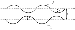
- the plurality of heating wires 314 are formed to extend in the vertical direction so as to connect the bus bars 312 and 313. Also, the plurality of heating wires 314 are disposed substantially in parallel. Each heating wire 314 can be formed in a straight line, or can have various shapes such as a waveform. In particular, by making each heating wire 314 into a sine wave shape, the distribution of heat becomes uniform, and it is possible to optically prevent the heating wire 314 from obstructing the field of view of the windshield. At this time, the crimp rate of the heating wire 314 can be, for example, 150% or less. The crimp rate is the ratio of the actual length of the heating wire 314 (the length following the curve) to the length between the heating wire 314 on the heat generating layer 31.
- the heating wire 314 is drawn in a straight line in the drawing, it may also include a waveform as described above.
- the line width of each heating wire 314 is preferably 1 to 30 ⁇ m, more preferably 5 to 20 ⁇ m, and particularly preferably 8 to 15 ⁇ m. Since the smaller the line width of the heating wire 314, the harder it is for visual recognition, it is suitable for the windshield according to the present embodiment. However, if the width of the heating wire 314 is reduced, the cross-sectional area is reduced, and thus the calorific value may be reduced as described above. Therefore, the lower limit of the line width of the heating wire 314 can be set as described above. On the other hand, when the line width of the heating wire 314 becomes large, it becomes easy to visually recognize, and the calorific value becomes large due to the increase of the sectional area. Therefore, the upper limit of the line width of the heating wire 314 is set as described above.
- the line width of the heating wire 314 is preferably 7 to 30 ⁇ m.
- the line width is preferably 7 to 30 ⁇ m.
- the line width is preferably 20 ⁇ m or less, and more preferably 15 ⁇ m or less.
- the voltage applied between both bus bars 312 and 313 is 20 to 50 V, it is preferably 1 to 10 ⁇ m.
- the heat generation amount can be increased by setting the line width to 1 ⁇ m or more.
- the line width refers to the line width of the largest portion of the cross-sectional shape of the heating wire 314.
- the cross-sectional shape of the heating wire 314 is trapezoidal, the width of the lower side is the line width, and when the cross-sectional shape of the heating wire 314 is circular, the diameter is the line width.
- the thickness of the heating wire 314 is preferably 30 ⁇ m or less, more preferably 20 ⁇ m or less, and particularly preferably 10 ⁇ m or less. As described above, when the thickness is reduced, the step between the heating wire 314 and the base member 311 is reduced, and generation of bubbles in the vicinity of the step can be suppressed at the time of manufacturing as described later. Further, the thickness of the heating wire 314 is preferably smaller than the line width of the heating wire 314. In other words, the aspect ratio of the cross section of the heating wire 314 is preferably 1 or less. This is because if the thickness is larger than the line width of the heating wire 314, for example, the heating wire 314 may fall over the base material 311, which may make manufacturing difficult or break.
- the thickness of the heating wire 314 is preferably thin in order to suppress the generation of bubbles as described above, but in order to achieve the required calorific value, the thickness of the heating wire 314 is increased It is preferable to increase the cross-sectional area. From this point of view, the thickness of the heating wire 314 is preferably 5 ⁇ m or more, although there is a possibility of generation of bubbles. In addition, as described later, if the thickness of the heating wire 314 is 10 ⁇ m or more, bubbles may be generated more. However, as the amount of heat generation per heating wire 3141 becomes large, flicker may occur, so it is desirable that the thickness be 30 ⁇ m or less as described above.
- the line width and thickness of the heating wire 314 can be measured, for example, by multiplying the microscope such as VHX-200 (manufactured by Keyence Corporation) by 1000 times.
- the pitch of the adjacent heating wires 314 is preferably 1.25 to 4.0 mm, more preferably 1.50 to 3.5 mm, and still more preferably 2.0 to 3.0 mm. preferable.
- the pitch is not the length of the gap between the adjacent heating wires 314, but is the length obtained by adding the line width of the heating wires 314 to the length of the gap between the adjacent heating wires 314.
- the upper limit value of the pitch By setting the upper limit value of the pitch in this manner, for example, when a predetermined calorific value (for example, 400 W / m 2 ) can be obtained in the entire windshield, the calorific value W of each heating wire 314 as described above Since the number of heating wires 314 can be increased by reducing the pitch, the reduction of the calorific value of the entire windshield can be prevented.
- the lower limit value of pitch has the following provisions as of November 2017 in Japan.
- Section 3 Item 5 (window glass) of the notification that defines the details of the safety standards for road transport vehicles, among the devices for preventing fogging of window glass, those embedded in the test area A , “The width of the device is 0.03 mm or less, and the density is 8 wires / cm (in the case where the conductor is embedded horizontally, 5 wires or less)”, but 8 wires / cm or less
- the pitch it is desirable for the pitch to be 1.25 mm or more.
- the distance L between the center lines of the heating wires 314 is the pitch of the heating wires 314.
- the distance L between the center lines D of the waves of the adjacent heating lines 314 can be twice or more the amplitude A of each heating line 314.
- the amplitude A is not particularly limited, but can be, for example, 3 mm or more.
- the pitch of heating wire 314 is preferably 1.25 mm or more, and more preferably 2.0 mm or more.
- the heating wire 314 may be formed in a sine wave.
- the positions of the concavities and convexities of the sine wave may be different between adjacent heating lines 314 or the pitch of the concavities and convexities may be different.
- region is in the range of the test area
- the length of the heating wire 314 can be, for example, 1000 mm or more. Alternatively, it may be 1100 mm or more, or 1200 mm or more. Furthermore, the resistance of the heating wire 314 is preferably 30 ⁇ or more, and more preferably 90 ⁇ or more. By thus increasing the length of the heating wire, the resistance R is increased based on the equation (2), so that the amount of heat generation is reduced, and flicker can be suppressed.
- measurement of resistance R of heating wire 314 is explained.
- measurement can be performed using a commercially available electrical resistance measuring instrument, as an example, digital multimeter 73200 series (made by YOKOGAWA) can be mentioned.
- digital multimeter 73200 series made by YOKOGAWA
- the measurement first select the heating wire to be measured.
- one terminal of the electrical resistance measuring instrument is connected to the vicinity of the bus bar 312 of the heating wire, and the other terminal is connected to the vicinity of the bus bar 313 of the heating wire.
- the heating wire is sandwiched between the outer glass plate 1 and the inner glass plate 2 and the terminal of the electrical resistance measuring device can not be connected to the heating wire, either the outer glass plate 1 or the inner glass plate 2 can be broken to measure the resistance R of the heating wire 314.
- the heating wire to be measured and the heating wire adjacent to the heating wire are connected by a bridge (not shown), the resistance R of the heating wire to be measured is cut after the bridge is cut. taking measurement.
- the calorific value per unit length in each heating wire 314 is, for example, 2.0 W / m or less when a voltage of 13.5 V or 48 V is applied between both bus bars 312 and 313, for example. Is more preferable, 1.5 W / m or less is more preferable, and 1.0 W / m or less is particularly preferable. When it is 2.0 W / m or less, flicker can be suppressed.
- the calorific value per unit area in the windshield is preferably 300 to 600 W / m 2 in order to effectively carry out antifogging and ice melting etc. More preferably, it is 400 W / m 2 or more, and particularly preferably 500 W / m 2 or more.
- the base material 311 is a transparent film supporting both the bus bars 312 and 313 and the heating wire 314, and the material is not particularly limited.
- the material is not particularly limited.
- it can be formed of polyvinyl butyral resin (PVB), ethylene vinyl acetate (EVA) or the like.
- both bus bars 312 and 313 and heating wire 314 can be formed of the same material, such as copper (or tin-plated copper), gold, aluminum, magnesium, cobalt, tungsten, silver or alloys of those metals, etc. And can be formed of various materials. Among these, it is preferable to use silver, copper, gold, and aluminum, which are materials having an electrical resistivity of 3.0 ⁇ 10 ⁇ 8 ⁇ m or less. As described above, when the electrical resistivity of the heating wire 314 is low, the resistance R is small based on the equation (2), and the amount of heat generation tends to be large. However, flicker can be suppressed by adjusting the pitch, length, cross-sectional area, and line width of the heating wire 314.
- the conductive materials may be printed directly on the glass plates 1 and 2 as long as the bus bars 312 and 313 and the heating wires 314 have a width of 10 ⁇ m or more.
- the glass sheet can be directly heated to form a heating wire, that is, since it is not necessary to heat the intermediate film at the time of forming the heating wire 314, the intermediate film is deformed to suppress the occurrence of perspective distortion. Can.
- the heating wire 314 can then be formed.
- the method is not particularly limited, but can be formed by various methods such as printing, etching, and transfer.
- the bus bars 312 and 313 and the heating wires 314 can be separately formed, or they can be integrally formed.
- integralally means that there is no break (seamless) between materials, and there is no interface.
- both bus bars 312 and 313 are formed on the base material 311, and the base material 311 of the portion corresponding to the bus bars 312 and 313 is peeled off and removed while leaving the base material 311 for the heating wire 314. The heating wire can then be placed on the substrate between the bus bars.
- metal foil is dry-laminated on the base material 311 via a primer layer.
- metal foil copper can be used, for example.
- by performing a chemical etching process using a photolithography method on the metal foil it is possible to integrally pattern both the bus bars 312 and 313 and the plurality of heating lines 314 on the base material 311.
- the line width of the heating wire 314 is to be reduced (for example, 15 ⁇ m or less)
- patterning may be performed by photolithography.
- the surface of the heating wire 314, ie, the surface by the side of the inner side glass plate 2, is blackened, and it can suppress that the heating wire 314 is visually recognized from vehicle inner side.
- a material for blackening there are copper nitride, copper oxide, nickel nitride, nickel chromium and the like, and blackening can be performed by plating using these materials.
- the two adhesive layers 32 and 33 are sheet-like members for sandwiching the heat generating layer 31 and bonding to the glass plates 1 and 2. Although both adhesive layers 32 and 33 are formed in the same size as both glass plates 1 and 2, both adhesive layers 32 and 32 are located at positions corresponding to the notches 21 and 22 of inner glass plate 2. Notches of the same shape are respectively formed.
- the adhesive layers 32 and 33 can be formed of various materials, and can be formed of, for example, polyvinyl butyral resin (PVB), ethylene vinyl acetate (EVA), or the like. In particular, polyvinyl butyral resin is preferable because it is excellent in penetration resistance as well as adhesiveness with each glass plate.
- a surfactant layer may be provided between the adhesive layers 32 and 33 and the heat generating layer 31. The surface of both layers can be modified by such surfactant, and the adhesion can be improved.
- the shape of the adhesive layers 32 and 33 is not particularly limited, and may be smaller than the glass plates 1 and 2.
- the interlayer 3 can have other configurations.
- the bus bars 312 and 313 and the heating wire 314 can be formed between the adhesive layers 32 and 33.
- the substrate 311 may have a high haze ratio depending on the material, which may reduce the transmittance of the laminated glass. Therefore, the transmittance of the laminated glass can be increased by not providing the substrate 311.
- the adhesive layers 32 and 33 may be either one. Therefore, for example, the intermediate film 3 can be configured by one adhesive layer, the bus bars 312 and 313, and the heating wire 314. When the number of adhesive layers is one, for example, when the first adhesive layer 32 is eliminated, the heating wire 314 comes in contact with the outer glass plate 1.
- the heating wire 314 comes in contact with the inner glass plate 2.
- it is suitable for removing the fogging that occurs on the inner glass plate 2.
- additional members may be stacked on the bus bars 312 and 313 to increase the thickness of the bus bars 312 and 313.
- the thickness of the additional member is not particularly limited, but the thickness may be determined according to the use in order to reduce the resistance value of the bus bars 312 and 313. For example, it can be 50 to 200 ⁇ m (eg, 100 ⁇ m). However, in the case of using an additional member, the above-described foam is easily generated.
- the total thickness of the intermediate layer 3 is not particularly limited, but is preferably 0.3 to 6.0 mm, more preferably 0.5 to 4.0 mm, and 0.6 to 2.0 mm. Being particularly preferred.
- the thickness of the base 311 of the heat generating layer 31 is preferably 5 to 200 ⁇ m, and more preferably 5 to 100 ⁇ m. Note that the provision of the base material 311 also has the possibility of the above-described generation of bubbles.
- the thickness of each of the adhesive layers 32 and 33 is preferably larger than the thickness of the heat generating layer 31. Specifically, it is preferably 0.05 to 2.0 mm, and 0.05 to 1.0 mm. It is further preferred that Furthermore, although the details will be described later, in consideration of the ease of heat radiation from the heating wire 314 to the glass plates 1 and 2, it is preferable that the thickness of each adhesive layer 32 and 33 be smaller. It is preferable that it is 05 to 0.4 mm. The thickness of both adhesive layers 32 and 33 may be the same or different.
- the thickness of the first adhesive layer 32 can be 30 to 70 ⁇ m (for example, 50 ⁇ m), and the thickness of the second adhesive layer 33 can be 500 to 900 ⁇ m (for example, 760 ⁇ m).
- the thickness of the first adhesive layer 32 is small, the heat from the heating wire 314 is easily transmitted to the outer glass plate 1, and the deicing performance is enhanced.
- this thickness is reversed between the first adhesive layer 32 and the second adhesive layer 33, the heat from the heating wire 314 is easily transmitted to the inner glass plate 2, and the antifogging performance is enhanced.
- the thickness of both the bus bars 312 and 313 and the heating wire 314 sandwiched therebetween be 3 to 20 ⁇ m.
- the thicknesses of the heat generating layer 31 and the adhesive layers 32 and 33 can be measured, for example, as follows. First, the cross section of the laminated glass is enlarged by 175 times and displayed by a microscope (for example, VH-5500 manufactured by Keyence Corporation). Then, the thicknesses of the heat generating layer 31 and the adhesive layers 32 and 33 are visually specified and measured. At this time, in order to eliminate variations due to visual observation, the number of measurements is made five times, and the average value is taken as the thickness of the heat generating layer 31 and the adhesive layers 32, 33.
- the thicknesses of the heat generating layer 31 and the adhesive layers 32 and 33 of the intermediate layer 3 do not have to be constant over the entire surface, and for example, they may be wedge-shaped for laminated glass used in a head-up display. In this case, the thickness of the heat generating layer 31 and the adhesive layers 32 and 33 of the intermediate layer 3 is measured at the place with the smallest thickness, that is, the lowermost side portion of the laminated glass.
- the intermediate layer 3 is wedge-shaped, the outer glass plate 1 and the inner glass plate 2 are not arranged in parallel, but such an arrangement is also included in the glass plate in the present invention.
- connection material 41 and 42 are for connecting the respective bus bars 312 and 313 and connection terminals (anode terminal or cathode terminal: not shown), and are formed in a sheet shape of a conductive material. Then, a voltage higher than 12 V, for example, a power supply voltage of 13.5 V is applied to this connection terminal.
- the connection material connected to the first bus bar 312 is referred to as a first connection material 41
- the connection material connected to the second bus bar 313 is referred to as a second connection material 42.
- the 1st connection material 41 is mainly demonstrated.
- the first connection member 41 is formed in a rectangular shape, and is sandwiched between the first bus bar 312 and the second adhesive layer 33. Then, the first bus bar 312 is fixed by the fixing material 5 such as solder.
- the fixing material 5 such as solder.
- the fixing material 5 it is preferable to use, for example, a solder having a low melting point of 150 ° C. or less so that it can be simultaneously fixed by an autoclave at the time of assembling the windshield described later.
- the first connecting member 41 extends from the first bus bar 312 to the upper end edge of the outer glass plate 1 and is exposed from the first notch 21 formed in the inner glass plate 2. And in this exposed part, the connection terminal to which the cable extended to the power supply is connected is connected by a fixing material such as solder.
- connection terminals are fixed to the portions exposed from the notches 21 and 22 of the inner glass plate 2 without the connection members 41 and 42 protruding from the end portions of both the glass plates 1 and 2 It has become.
- both the connection materials 41 and 42 are formed with thin material, after bending, as shown in FIG. 2, an edge part can be fixed to the bus-bar 312 with the fixing material 5.
- a shielding layer 7 is laminated on a dark ceramic such as black on the periphery of the laminated glass.
- the shielding layer 7 shields the view from inside and outside the vehicle, and is laminated along the four sides of the laminated glass.
- the bus bars 312 and 313 are disposed at positions covered by the shielding layer 7.
- the shielding layer 7 covers all the outer edges of the bus bars 312 and 313 and the vicinity thereof, and covers at least the step between the outer edges of the bus bars 312 and 313 and the base member 311 and the vicinity thereof.
- the base 311 is smaller than the adhesive layers 32 and 33, at least the step between the base 311 and the adhesive layers 32 and 33 and the vicinity thereof are covered.
- Reference numeral 7 in the figure indicates the inner edge of the shielding layer 7.
- the shielding layer 7 may have various modes such as only the outer surface of the outer glass plate 1, only the inner surface of the outer glass plate 1, or the inner surface of the outer glass plate 1 and the inner surface of the inner glass plate 2. In addition, if the shielding layer 7 is provided at least on the outer glass plate 1, it is possible to prevent the bubbles from being visually recognized from the outside of the vehicle. On the other hand, when the second shielding layer is provided on the inner glass plate 2, it is possible to prevent bubbles from being visually recognized from the inside of the vehicle. However, it depends on the structure of the vehicle whether the second shielding layer prevents the bubbles from being viewed from the inside of the vehicle. That is, when the foam is concealed by fitting the laminated glass into the vehicle body, the second shielding layer may be considered unnecessary. However, in order to improve the quality of the laminated glass itself, or when the foam is not hidden in the vehicle body, it is preferable to provide a second shielding layer to hide the foam also from the inside of the car.
- the ceramic can be formed by screen printing, but it can also be produced by transferring a baking transfer film onto a glass plate and baking it.
- screen printing for example, polyester screen: 355 mesh, coat thickness: 20 ⁇ m, tension: 20 Nm, squeegee hardness: 80 degrees, mounting angle: 75 °, printing speed: 300 mm / s, drying furnace Drying at 150 ° C. for 10 minutes can form a ceramic.
- the shielding layer 7 can also be formed by sticking a shielding film made of a dark resin, in addition to laminating ceramics.
- Windshield manufacturing method> Next, a method of manufacturing the windshield will be described. First, the manufacturing line of a glass plate is demonstrated.
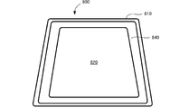
- FIG. 4 is a side view of the furnace through which the mold passes
- FIG. 5 is a plan view of the mold.
- this forming die 800 is provided with a frame-like die main body 810 that substantially matches the outer shape of both the glass plates 1 and 2. Since the mold body 810 is formed in a frame shape, it has an internal space 820 penetrating in the vertical direction inside. Then, the peripheral edge portions of the flat glass plates 1 and 2 are placed on the upper surface of the mold body 810. Therefore, heat is applied to the glass plates 1 and 2 through the internal space 820 from a heater (not shown) disposed on the lower side.
- a heater not shown
- both the glass plates 1 and 2 are softened by heating and curved downward by their own weight.
- the shielding board 840 for shielding heat may be arrange
- the heater can be provided not only below the forming die 800 but also above it.
- both the glass plates 1 and 2 are stacked downward inside by the own weight than the peripheral portion and are formed into a curved surface.
- both the glass plates 1 and 2 are carried from the heating furnace 802 to the annealing furnace 803, and annealing is performed. Thereafter, both glass plates 1 and 2 are carried out of the annealing furnace 803 to the outside and allowed to cool.
- the intermediate layer 3 is sandwiched between the outer glass plate 1 and the inner glass plate 2.
- the outer glass plate 1, the first adhesive layer 32, the heat generating layer 31, the second adhesive layer 33, and the inner glass plate 2 are laminated in this order.
- the heat generating layer 31 directs the surface on which the first bus bar 312 and the like are formed to the second adhesive layer 33 side.
- the upper and lower end portions of the heat generating layer 31 are disposed inside the notches 21 and 22 of the inner glass plate 2.
- the notches of the first and second adhesive layers 32 and 33 are made to coincide with the notches 21 and 22 of the inner glass plate 2.
- connection members 41 and 42 are inserted between the heat generating layer 31 and the second adhesive layer 33 from the notch portions 21 and 22, respectively.
- a low melting point solder is applied to each of the connection members 41 and 42 as the fixing member 5 so that the solder is disposed on each of the bus bars 312 and 313.
- the laminated body in which both the glass plates 1 and 2, the intermediate layer 3, and the connecting members 41 and 42 are laminated is put in a rubber bag and prebonded at about 70 to 110 ° C. under vacuum suction.
- Other pre-adhesion methods are possible, and the following method may be adopted.
- the laminate is heated at 45 to 65 ° C. in an oven.
- this laminate is pressed by a roll at 0.45 to 0.55 MPa.
- the laminate is again heated at 80 to 105 ° C. in an oven, and then pressed again by a roll at 0.45 to 0.55 MPa.
- pre-adhesion is completed.
- the pre-adhered laminate is subjected to main adhesion by means of an autoclave at, for example, 8 to 15 atm at 100 to 150.degree.
- the main adhesion can be performed under the conditions of 14 ° C. and 135 ° C.
- the adhesive layers 32 and 33 are adhered to the glass plates 1 and 2 with the heat generating layer 31 interposed therebetween through the preliminary bonding and the main bonding described above. Further, the solder of the connection members 41 and 42 is melted, and the connection members 41 and 42 are fixed to the bus bars 312 and 313, respectively.
- the laminated glass according to the present embodiment is manufactured.
- the curved windshield can also be manufactured by methods other than this, for example, press work.
- connection terminals are fixed to the connection members 41 and 42, respectively. Thereafter, when each connection terminal is energized, a current is applied to the heating wire 314 through the connection members 41 and 42 and the bus bars 312 and 313 to generate heat. By this heat generation, it is possible to remove the fogging of the inner surface of the windshield or to de-ice the outer surface of the windshield.
- the shielding layer 7 covers all the outer edges of the bus bars 312 and 313 and the vicinity thereof, and covers at least the step between the outer edges of the bus bars 312 and 313 and the base member 311 and the vicinity thereof. ing. Therefore, bubbles generated in the step between the bus bars 312 and 313 and the base material 311 can be hidden by the shielding layer 7. Therefore, even if bubbles are generated, they can be viewed from outside the vehicle.
- the generation of bubbles can be suppressed.
- the example of the windshield which comprised the intermediate film 3 as follows is demonstrated.
- the following heat generating layer 31 is disposed between the adhesive layers 32 and 33.
- the numerical values in the table are thickness.
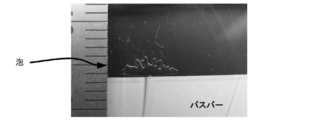
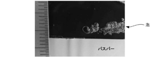
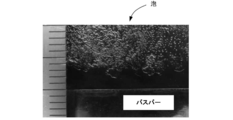
- the bus bars 312 and 313 and the heating wire 314 are integrally formed, and have the same thickness. Further, the appearance of the following table is obtained by photographing the vicinity of the bus bar.
- the base material 311 is not provided in the heat generating layer 31, a step is generated between the bus bars 312 and 313 and the heating wire 314 and the adhesive layers 32 and 33, air remains at the time of manufacture. , A bubble has occurred.
- the bubbles are not noticeable, but in the reference examples 3 and 4, the bubbles are noticeable and the range is wide. Therefore, although the bus bars 312 and 313 can be covered with the shielding layer 7 in the third and fourth embodiments, when the bubble range is wide, the shielding layer 7 must also be spread. Therefore, the thicknesses of the bus bars 312 and 313 and the heating wire 314 are preferably 30 ⁇ m or less.
- the thickness of the entire layer (functional layer) 31 is preferably in the range of 5 to 200 ⁇ m.
- the thickness is preferably in the range of 5 to 500 ⁇ m.
- the inventor has found that the above-mentioned flicker occurs especially when the temperature of the heating wire 314 and the temperature around it exceeds about 60 ° C. Therefore, the inventor of the present invention has determined that when a voltage of 13.5 V is applied between the bus bars 312 and 313 so that the temperature of the heating wire 314 and the surrounding temperature does not exceed about 60 ° C. It has been found that the flicker is prevented by setting the calorific value of no more than 2.0 W / m. Therefore, in the windshield according to the present embodiment, when a voltage of 13.5 V is applied between the bus bars 312 and 313, the calorific value per unit length of each heating wire 314 is 2.0 W / m or less. Because of this, the temperature of the heating wire 314 and its surroundings can be suppressed to about 60.degree. C. or less, and as a result, it is possible to prevent flicker when looking out of the vehicle through the windshield.
- heating wire for example, in the case of a windshield that requires 464 W / m 2 as the calorific value for a region of 1180 mm wide and 958 mm long at a voltage of 13.5 V, set as shown in FIG. Can.
- the shapes of the heating wires 314 for satisfying the calorific value are as shown in reference examples 5 to 16 shown in FIG.
- the pitch of the heating wire 314 is required to be 1.25 mm or more according to the above-mentioned definition, it is preferable to use the heating wire of Reference Examples 15 and 16. Therefore, in consideration of this pitch, the line width of the heating wire 314 is preferably 10 ⁇ m or more.
- the heating wire can be set as shown in FIG.
- the calorific value per unit length of each heating wire is preferably 2.0 W / m or less.
- the pitch is preferably 4.0 mm or less.
- the line width of the heating wire is preferably approximately 10 ⁇ m or less, and more preferably 8 ⁇ m or less.
- both bus bars 312 and 313 and heating wire 314 are formed of the same material, the linear expansion coefficients of both bus bars 312 and 313 and heating wire 314 become the same.
- both bus bars 312 and 313 and heating wire 314 are formed of different materials, they have different coefficients of linear expansion. For example, when these members are separately manufactured and fixed, severe conditions such as heat cycle test etc. Although there is a possibility that the heating wire may peel from the bus bar due to the environmental change, and the two glass plates constituting the laminated glass may float up due to this, as in this embodiment, both bus bars Such defects can be prevented if the layers 312 and 313 and the heating wire 314 are formed of the same material.
- the current value may be controlled so that the upper limit of the heating temperature is, for example, 70 to 80 ° C. to prevent the occurrence of glass cracks. Desired.
- the heating wire can not be controlled to generate heat sufficiently.
- the heating wire can also be controlled so as to be capable of generating heat as a whole.
- the two bus bars 312 and 313 are connected to the external terminals using two connection members 41 and 42.
- a wide bus bar is prepared, and It may be considered to replace the connection material by cutting unnecessary portions and exposing a part from the notches 21 and 22. However, this may cause local heat generation at the corners of the cut bus bar.
- the separate connecting members 41 and 42 are fixed to the bus bars 312 and 313, such local heat generation can be prevented.
- the heat generating layer 31 can have various shapes.
- the sheet-like heat generating layer 31 in which both the bus bars 312 and 313 and the heating wire 314 are formed on the base material 311 is prepared in advance, cut appropriately, and formed into an appropriate shape. It can be placed between 1 and 2. Therefore, for example, if the edge of the glass plates 1 and 2 is curved, the edge of the substrate 311 may be curved accordingly.
- various shapes such as a smaller shape than the glass plates 1 and 2 It can be shaped.
- the glass plates 1 and 2 can also be made into various shapes other than a perfect rectangle.
- both the bus bars 312 and 313 and the heating wire 314 are disposed on the base material 311, but at least the heating wire 314 may be disposed. Therefore, for example, both bus bars 312 and 313 can be disposed between the adhesive layers 32 and 33.
- the adhesive layers 32 and 33 may not be provided, and the bus bars 312 and 313 and the base material 311 supporting the heating wire 314 may be disposed between the two glass plates 1 and 2.
- the substrate 311 plays a role as an adhesive layer.
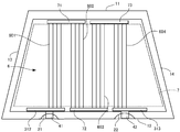
- the configuration of the heating wire 314 is not particularly limited, and various aspects are possible. This point will be described with reference to FIG.
- the example in FIG. 12 is different from the above embodiment mainly in the arrangement of the bus bars and the heating wires, so only the different parts will be described below, and the same configuration will be assigned the same reference numerals and the description will be omitted. Do.
- the plurality of heating wires 6 are arranged in parallel so as to connect both bus bars 312 and 313.
- Each heating wire 6 is composed of three portions and two folded portions. That is, a first portion 61 extending from the first bus bar 312 to a position approaching the second bus bar 313 and a position extending close to the first bus bar 312 from the lower end of the first portion 61 via the first folded portion 64.
- a second portion 62 extending up to the bottom, and a third portion 63 extending downward from the upper end of the second portion 62 via the second folded portion 65 and connected to the second bus bar 313 are provided.
- a plurality of heating wires 6 formed in this manner are arranged at predetermined intervals in the left-right direction of both bus bars 312, 313.
- each heating wire 6 can be made longer by providing the folded portions 64 and 65 in each heating wire. By these, the calorific value in each heating wire 6 can be made small.
- the form of the heating wire 6 is not particularly limited, and in the present embodiment, the two folded portions 64 and 65 are formed to have two or more folded portions.
- the length of the heating wire 6 extending between can also be made longer.
- each heating wire 314 a relay bus-bar like FIG. 13 can also be provided. This point will be described in detail.
- the first bus bar 312 is disposed on the left side of the lower side 12 of each glass plate 1, 2, and the second bus bar 313 is disposed along the right side of the lower side 12.
- the strip-like first relay bus bar 71 on the left side of the upper side 11 of the glass plates 1 and 2, and the strip-like second relay bus bar 72 between the first and second bus bars 312 and 313 on the lower side 12.
- a band-shaped third relay bus bar 73 is provided on the right side of the upper side 11 of the second.
- the first relay bus bar 71 is disposed at a position facing the first bus bar 312 and the second relay bus bar 72, and formed to have substantially the same length from the left end of the first bus bar 312 to the vicinity of the center of the second relay bus bar 72.
- the third relay bus bar 73 is disposed at a position facing the second relay bus bar 72 and the second bus bar 313, and has substantially the same length from the left end of the first bus bar 312 to the vicinity of the center of the second relay bus bar 72. It is formed.
- the plurality of heating wires 6 are constituted by four parts. That is, the plurality of heating wires 6 respectively have a first portion 601 connecting the first bus bar 312 and the first relay bus bar 71, a second portion 602 connecting the first relay bus bar 71 and the second relay bus bar 72, A third portion 603 connecting the second relay bus bar 72 and the third relay bus bar 73 and a fourth portion 604 connecting the third relay bus bar 73 and the second bus bar 313 are formed.
- the plurality of first portions 601 extend generally in parallel from the first bus bar 312 upward, and are connected to the left half of the first relay bus bar 71.
- the plurality of second portions 602 extend generally in parallel from the right half of the first relay bus bar 71 downward, and are connected to the left half of the second relay bus bar 72. Further, the plurality of third portions 603 extend generally in parallel from the left half of the second relay bus bar 72 upward, and are connected to the third relay bus bar 73. The plurality of fourth portions 604 extend generally in parallel from the right half of the third relay bus bar 73 downward, and are connected to the second bus bar 213.
- the three relay bus bars 71 to 73 are provided between the first bus bar 312 and the second bus bar 313, and the plurality of heating wires 6 arranged in parallel via these are the first bus bar 312 and the first bus bar 312 It is configured to connect the two bus bars 313. Therefore, the length of the heating wire 6 between the first bus bar 312 and the second bus bar 313 can be increased. By these, the calorific value in each heating wire 6 can be made small.
- both bus bars 312 and 313 are disposed along the lower side 12, but may be disposed along the upper side 11. That is, from FIG. 9, both bus bars 312 and 313 and three relay bus bars 71 to 73 can be disposed at vertically opposite positions.
- the number of relay bus bars is not particularly limited, and two or four or more relay bus bars may be provided, and both ends of the heating wire are connected to the first bus bar 312 and the second bus bar 313 through all the relay bus bars. It should just be.
- Adjacent heating wires 314 can also be connected by at least one bridge. Thereby, even if one heating wire 314 is disconnected, for example, it becomes possible to conduct electricity from the adjacent heating wire 314.
- the position and number of bridges are not particularly limited.
- the shape of the bridge is not particularly limited, and may be variously arranged such as being arranged to extend diagonally or to be corrugated.
- the bridge can be formed of the same metal material as the heating wire 314, and can be formed integrally with the heating wire 314.
- connection members 41 and 42 and the configuration of the notches 21 and 22 of the inner glass plate 2 are not particularly limited.
- small notches about the thickness of the connecting members 41 and 42 are formed in the inner glass plate 2, and the connecting members 41 and 42 extending from the bus bars 312 and 313 are folded at the notches. It can also be stuck on the surface. By doing this, it is possible to prevent the connection members 41 and 42 from projecting in the surface direction from the end of the laminated glass.
- the shape of the glass plates 1 and 2 is not particularly limited, and may be any shape that can identify the upper side 11, the lower side 12, the left side 13 and the right side 14 in the outer shape, and may not necessarily be rectangular.
- Each side 11 to 14 may be a straight line or a curved line.
- the bus bars 312 and 313 are respectively disposed along the upper side and the lower side of the glass plate, but the bus bars are arranged along the left side and the right side of the glass plate so that the heating line extends in the lateral direction. It can also be done.
- the heat generating layer 31 is provided as the functional layer according to the present invention, but a functional layer having other functions may be provided.
- a functional layer having other functions for example, an infrared reflective film, a light control film, a crime prevention sheet, a color film, a film for a head-up display, etc. can be provided. Then, even when such a functional layer is provided, if a step is formed between the adhesive layers 32 and 33, bubbles may be generated as described above, so the step is covered by the shielding layer 7 It will be necessary.
- the functional layer 31 when an infrared reflective film is used as the functional layer 31, there is a possibility that the edge of the film reacts with the plasticizer to discolor. Therefore, even when such a functional layer 31 is provided, the color change can be shielded by the shielding layer 7.
- Films such as an infrared light reflective film, a light control film, a security sheet, and a color film may cause wrinkles particularly at the edge portion of the laminated glass depending on the extension of the film. Even in such a case, the shielding layer 7 can shield the wrinkles.
- the shape of the shielding layer 7 is not particularly limited, and can be formed along the peripheral edge of the laminated glass as in the above embodiment, and at least at a position covering the step between the heat generating layer 31 and the adhesive layers 32 and 33 It should just be arrange
Abstract
Provided is a laminated glass in which a functional layer is disposed between two glass plates and which is capable of improving the quality of appearance thereof. The laminated glass according to the present invention is provided with: an outer glass plate having a first side and a second side opposite to the first side; an inner glass plate opposite to the outer glass plate and having substantially the same shape as the outer glass plate; an intermediate film disposed between the outer glass plate and the inner glass plate; and a shielding layer formed on a surface of the outer glass plate, wherein the intermediate film includes an adhesive layer and a functional layer supported by the adhesive layer, and at least a portion of an outer peripheral edge of the functional layer has an inner portion positioned further inside than an outer peripheral edge of the adhesive layer, and the shielding layer is at least disposed so as to cover between the inner portion of the functional layer and the outer peripheral edge of the adhesive layer.
Description
本発明は、合わせガラスに関する。
The present invention relates to laminated glass.
気温の低い日や寒冷地では、自動車のウインドシールドが曇ることがあり、運転に支障を来している。そのため、ウインドシールドの曇りを除去する種々の方法が提案されている。例えば、特許文献1には、ウインドシールドの内部に、バスバー及び加熱線を配置し、その発熱によって曇りを除去することが開示されている。
On cold days or in cold climates, windshields of cars can be overcast, which hinders driving. Therefore, various methods have been proposed for removing windshield fogging. For example, Patent Document 1 discloses that a bus bar and a heating wire are disposed inside a windshield and heat generation removes fogging.
ところで、上記ウインドシールドは、2枚のガラス板の間に接着層とともにバスバーなどを配置した合わせガラスにより形成されている。そして、この合わせガラスを作製する際には、接着層上にバスバーを配置した上で、これらを2枚のガラス板の間に挟み圧力を付与して接着する。しかしながら、バスバーと接着層との間には段差が生じるため、接着時に、この段差に空気が残るおそれがあった。そして、このような空気が残ると、完成した合わせガラスには、この空気が泡として視認可能となり、製品としての品質の低下を招いていた。なお、このような泡の発生は、バスバーだけではなく、2枚のガラス板の間に、例えば、赤外線反射フィルム、調光フィルムなどの機能層を挟んだ配置したときにも生じ得る問題である。
The windshield is formed of laminated glass in which a bus bar and the like are disposed together with an adhesive layer between two glass plates. And when producing this laminated glass, after arrange | positioning a bus-bar on an adhesive layer, these are pinched | interposed between two glass plates, pressure is applied and it adhere | attaches. However, since a step is generated between the bus bar and the adhesive layer, air may be left in the step during bonding. Then, when such air remains, this air can be visually recognized as bubbles in the finished laminated glass, resulting in deterioration of the product quality. In addition, generation | occurrence | production of such a bubble is a problem which may arise also when not only a bus-bar but the functional layer, such as an infrared reflective film and a light control film, is pinchedly arranged between two glass plates, for example.
ところで、上記機能層は、その外周縁がガラス板の外周縁と一致するように形成することができ、このようにすれば、上記のような段差が生じないため、泡の発生を防止することができる。しかしながら、このようにすると、機能層の外周縁がガラス板の間から露出するため、ここからガラス板の間に水が浸入するおそれがある。これにより、合わせガラスが膨れると、本来の合わせガラスの機能を失うおそれがある。さらに、次のような問題もある。すなわち、各ガラス板の端縁は、断面円弧状に形成されることがあるため、機能層の外周縁がガラス板の外周縁と一致していると、接着層同士が接着しない可能性があり、これによって、接着層や機能層にシワが生じる可能性がある。そこで、接着層の外周縁の位置を、外側ガラス位置の位置より中央側に位置させる(例えば、数mm~30mm程度)ことで、水の浸入を防止することができる。しかしながら、このように、接着層の外周縁の位置をガラス板の外周縁よりも内側にすると、上述した泡が生じるおそれがある。
By the way, the above-mentioned functional layer can be formed so that the outer peripheral edge may be in agreement with the outer peripheral edge of a glass plate, and since it does not produce the above-mentioned level difference if it does in this way, generation of bubbles is prevented. Can. However, in this case, since the outer peripheral edge of the functional layer is exposed from between the glass plates, there is a possibility that water may infiltrate between the glass plates from here. As a result, when the laminated glass is swollen, there is a risk of losing the original function of the laminated glass. There are also the following problems. That is, since the edge of each glass plate may be formed in a circular arc shape in cross section, if the outer periphery of the functional layer matches the outer periphery of the glass plate, the adhesive layers may not adhere to each other. However, this may cause wrinkles in the adhesive layer or the functional layer. Therefore, the entry of water can be prevented by positioning the position of the outer peripheral edge of the adhesive layer closer to the center than the position of the outer glass position (for example, about several mm to about 30 mm). However, when the position of the outer peripheral edge of the adhesive layer is located inside the outer peripheral edge of the glass plate as described above, the above-mentioned bubbles may occur.
本発明は、上記問題を解決するためになされたものであり、2枚のガラス板の間に機能層を配置した合わせガラスであって、見た目の品質を向上することができる、合わせガラスを提供することを目的とする。
The present invention has been made to solve the above problems, and provides a laminated glass in which a functional layer is disposed between two glass plates, which can improve the quality of appearance. With the goal.
項1:第1辺と、及び前記第1辺と対向する第2辺を有する外側ガラス板と、
前記外側ガラス板と対向配置され、前記外側ガラス板と略同形状の内側ガラス板と、
前記外側ガラス板と内側ガラス板との間に配置される中間膜と、
前記外側ガラス板の表面に形成される遮蔽層と、
を備え、
前記中間膜は、
接着層と、
前記接着層に支持される機能層と、
を備え、
前記機能層の外周縁の少なくとも一部は、前記接着層の外周縁よりも内側に位置する、内側部位を有しており、
前記遮蔽層は、少なくとも、前記機能層の内側部位と前記接着層の外周縁との間を覆うように配置されている、合わせガラス。 Item 1: An outer glass plate having a first side and a second side opposite to the first side,
An inner glass plate disposed opposite to the outer glass plate and having substantially the same shape as the outer glass plate;
An interlayer disposed between the outer glass plate and the inner glass plate;
A shielding layer formed on the surface of the outer glass plate;
Equipped with
The interlayer is
Adhesive layer,
A functional layer supported by the adhesive layer;
Equipped with
At least a part of the outer peripheral edge of the functional layer has an inner portion located inside the outer peripheral edge of the adhesive layer,
The laminated glass, wherein the shielding layer is disposed to cover at least an inner portion of the functional layer and an outer peripheral edge of the adhesive layer.
項2:前記遮蔽層は、前記外側ガラス板の前記中間膜側の表面に位置している項1の合わせガラス。
Item 2: The laminated glass of Item 1, wherein the shielding layer is located on the surface on the intermediate film side of the outer glass plate.
項3:前記内側ガラス板の前記中間膜とは反対側の表面に設けられる第2遮蔽層をさらに備えている、項2に記載の合わせガラス。
Item 3: The laminated glass according to Item 2, further comprising a second shielding layer provided on the surface of the inner glass plate opposite to the intermediate film.
項4:前記遮蔽層は、前記外側ガラス板の外周縁の全周に亘って形成されている、項1から3のいずれかに記載の合わせガラス。
Item 4: The laminated glass according to any one of Items 1 to 3, wherein the shielding layer is formed over the entire periphery of the outer peripheral edge of the outer glass plate.
項5:前記遮蔽層は、前記外側ガラス板と前記中間膜との間に配置されている、項1から4のいずれかに記載の合わせガラス。
Item 5: The laminated glass according to any one of Items 1 to 4, wherein the shielding layer is disposed between the outer glass plate and the intermediate film.
項6:前記機能層の厚みが、5~200μmである、項1から5のいずれかに記載の合わせガラス。
Item 6: The laminated glass according to any one of Items 1 to 5, wherein the thickness of the functional layer is 5 to 200 μm.
項7:前記機能層は、
少なくとも一部が前記第1辺側の端部に沿って延びる第1バスバーと、
少なくとも一部が前記第2辺側の端部に沿って延びる第2バスバーと、
前記第1バスバーと第2バスバーとを連結するように配置された複数の加熱線と、
を備え、
前記第1バスバー及び第2バスバーの外周縁の一部が、前記内側部位を構成しており、
前記遮蔽層は、前記両バスバー及びその周縁近傍を覆うように形成されている、項1から6のいずれかに記載の合わせガラス。 Item 7: The functional layer is
A first bus bar, at least a portion of which extends along the end on the first side;
A second bus bar, at least a portion of which extends along an end on the second side;
A plurality of heating wires arranged to connect the first bus bar and the second bus bar;
Equipped with
A part of the outer peripheral edge of the first bus bar and the second bus bar constitutes the inner portion,
7. The laminated glass according to any one of items 1 to 6, wherein the shielding layer is formed to cover both the bus bars and the vicinity of the peripheral edge thereof.
項8:前記機能層は、前記両バスバー及び加熱線を支持する支持層をさらに有しており、
前記支持層が、前記接着層と接触する、項7に記載の合わせガラス。 Item 8: The functional layer further includes a support layer that supports both the bus bars and the heating wire,
Item 8. The laminated glass according toitem 7, wherein the support layer is in contact with the adhesive layer.
前記支持層が、前記接着層と接触する、項7に記載の合わせガラス。 Item 8: The functional layer further includes a support layer that supports both the bus bars and the heating wire,
Item 8. The laminated glass according to
項9:前記両バスバーは、複数の金属層を積層することで形成されている、項7または8に記載の合わせガラス。
Item 9: The laminated glass according to item 7 or 8, wherein both bus bars are formed by laminating a plurality of metal layers.
項10:前記加熱線のピッチは、1.25~4mmである、項7から9のいずれかに記載の合わせガラス。
Item 10: The laminated glass according to any one of Items 7 to 9, wherein the pitch of the heating wire is 1.25 to 4 mm.
項11:前記加熱線の発熱量が、2.0W/m以下である、項7から10のいずれかに記載の合わせガラス。
Item 11: The laminated glass according to any one of Items 7 to 10, wherein the calorific value of the heating wire is 2.0 W / m or less.
項12:前記加熱線の厚みが、30μm以下である、項7から11のいずれかに記載の合わせガラス。
Item 12: The laminated glass according to any one of Items 7 to 11, wherein the thickness of the heating wire is 30 μm or less.
項13:前記加熱線における前記接着層側の面の幅は、1~30μmである、項7から12のいずれかに記載の合わせガラス。
Item 13: The laminated glass according to any one of Items 7 to 12, wherein the width of the surface on the adhesive layer side in the heating wire is 1 to 30 μm.
項14:前記両バスバーに印加される電圧が20V未満であり、
前記加熱線における前記接着層側の面の幅は、前記加熱線の厚み以上の長さを有しており、
前記加熱線の幅が9~20μmである、項7から13のいずれかに記載の合わせガラス。 Item 14: The voltage applied to both the bus bars is less than 20 V,
The width of the surface on the side of the adhesive layer in the heating wire has a length equal to or greater than the thickness of the heating wire,
Item 14. The laminated glass according to any one of Items 7 to 13, wherein the width of the heating wire is 9 to 20 μm.
前記加熱線における前記接着層側の面の幅は、前記加熱線の厚み以上の長さを有しており、
前記加熱線の幅が9~20μmである、項7から13のいずれかに記載の合わせガラス。 Item 14: The voltage applied to both the bus bars is less than 20 V,
The width of the surface on the side of the adhesive layer in the heating wire has a length equal to or greater than the thickness of the heating wire,
項15:前記両バスバーに印加される電圧が20~50Vであり、
前記加熱線における前記接着層側の面の幅は、前記加熱線の厚み以上の長さを有しており、
前記加熱線の幅が1~10μmである、項7から13のいずれかに記載の合わせガラス。 Item 15: The voltage applied to the both bus bars is 20 to 50 V,
The width of the surface on the side of the adhesive layer in the heating wire has a length equal to or greater than the thickness of the heating wire,
Item 14. The laminated glass according to any one of Items 7 to 13, wherein the width of the heating wire is 1 to 10 μm.
前記加熱線における前記接着層側の面の幅は、前記加熱線の厚み以上の長さを有しており、
前記加熱線の幅が1~10μmである、項7から13のいずれかに記載の合わせガラス。 Item 15: The voltage applied to the both bus bars is 20 to 50 V,
The width of the surface on the side of the adhesive layer in the heating wire has a length equal to or greater than the thickness of the heating wire,
本発明に係る合わせガラスによれば、2枚のガラス板の間に機能層を配置したものであっても、見た目の品質を向上することができる。
According to the laminated glass of the present invention, even when the functional layer is disposed between two glass plates, the quality of appearance can be improved.
以下、本発明に係る合わせガラスをウインドシールドに適用した一実施形態について、図面を参照しつつ説明する。図1は、本実施形態に係るウインドシールドの平面図、図2は図1の断面図である。図1及び図2に示すように、本実施形態に係るウインドシールドは、外側ガラス板1、内側ガラス板2、及びこれらガラス板1,2の間に配置される中間層3を備えている。また、内側ガラス板2の上端部及び下端部には、切欠き部21,22がそれぞれ形成されており、各切欠き部21,22では、中間層3から延びる接続材41,42がそれぞれ露出している。以下、各部材について説明する。
Hereinafter, an embodiment in which the laminated glass according to the present invention is applied to a windshield will be described with reference to the drawings. FIG. 1 is a plan view of a windshield according to the present embodiment, and FIG. 2 is a cross-sectional view of FIG. As shown in FIGS. 1 and 2, the windshield according to the present embodiment includes an outer glass plate 1, an inner glass plate 2, and an intermediate layer 3 disposed between the glass plates 1 and 2. Further, notches 21 and 22 are respectively formed at the upper end and the lower end of the inner glass plate 2, and the connecting members 41 and 42 extending from the intermediate layer 3 are exposed at the respective notches 21 and 22. doing. Each member will be described below.
<1.合わせガラスの概要>
<1-1.ガラス板>
各ガラス板1,2は、ともに、下辺12が上辺11よりも長い矩形状に形成されてする。すなわち、上辺11、下辺12、両側辺(左辺13,右辺14)で囲まれた台形状に形成されている。そして、上述したように、内側ガラス板2の上端部及び下端部には、円弧状の切欠き部がそれぞれ形成されている。以下では、内側ガラス板2の上端部に形成された切欠き部を第1切欠き部21、下端部に形成された切欠き部を第2切欠き部22と称することとする。また、各ガラス板1,2としては、公知のガラス板を用いることができ、熱線吸収ガラス、一般的なクリアガラスやグリーンガラス、またはUVグリーンガラスで形成することもできる。但し、これらのガラス板1、2は、自動車が使用される国の安全規格に沿った可視光線透過率を実現する必要がある。例えば、外側ガラス板1により必要な日射吸収率を確保し、内側ガラス板2により可視光線透過率が安全規格を満たすように調整することができる。以下に、クリアガラス、熱線吸収ガラス、及びソーダ石灰系ガラスの組成の一例を示す。 <1. Outline of laminated glass>
<1-1. Glass plate>
Each of theglass plates 1 and 2 is formed in a rectangular shape in which the lower side 12 is longer than the upper side 11. That is, it is formed in a trapezoidal shape surrounded by the upper side 11, the lower side 12, and both sides (left side 13 and right side 14). And as above-mentioned, the circular-arc-shaped notch part is formed in the upper end part and lower end part of the inner side glass plate 2, respectively. Hereinafter, the notch formed in the upper end of the inner glass plate 2 will be referred to as a first notch 21 and the notch formed in the lower end will be referred to as a second notch 22. Moreover, as each glass plate 1 and 2, a well-known glass plate can be used and it can also form with heat ray absorption glass, general clear glass, green glass, or UV green glass. However, these glass plates 1 and 2 need to realize visible light transmittance in accordance with the safety standard of the country where the automobile is used. For example, the required solar radiation absorptivity can be secured by the outer glass plate 1, and the visible light transmittance can be adjusted by the inner glass plate 2 so that the safety standard is satisfied. Below, an example of a composition of clear glass, heat ray absorption glass, and soda lime type glass is shown.
<1-1.ガラス板>
各ガラス板1,2は、ともに、下辺12が上辺11よりも長い矩形状に形成されてする。すなわち、上辺11、下辺12、両側辺(左辺13,右辺14)で囲まれた台形状に形成されている。そして、上述したように、内側ガラス板2の上端部及び下端部には、円弧状の切欠き部がそれぞれ形成されている。以下では、内側ガラス板2の上端部に形成された切欠き部を第1切欠き部21、下端部に形成された切欠き部を第2切欠き部22と称することとする。また、各ガラス板1,2としては、公知のガラス板を用いることができ、熱線吸収ガラス、一般的なクリアガラスやグリーンガラス、またはUVグリーンガラスで形成することもできる。但し、これらのガラス板1、2は、自動車が使用される国の安全規格に沿った可視光線透過率を実現する必要がある。例えば、外側ガラス板1により必要な日射吸収率を確保し、内側ガラス板2により可視光線透過率が安全規格を満たすように調整することができる。以下に、クリアガラス、熱線吸収ガラス、及びソーダ石灰系ガラスの組成の一例を示す。 <1. Outline of laminated glass>
<1-1. Glass plate>
Each of the
(クリアガラス)
SiO2:70~73質量%
Al2O3:0.6~2.4質量%
CaO:7~12質量%
MgO:1.0~4.5質量%
R2O:13~15質量%(Rはアルカリ金属)
Fe2O3に換算した全酸化鉄(T-Fe2O3):0.08~0.14質量% (Clear glass)
SiO 2 : 70 to 73% by mass
Al 2 O 3 : 0.6 to 2.4 mass%
CaO: 7 to 12% by mass
MgO: 1.0 to 4.5 mass%
R 2 O: 13 to 15% by mass (R is an alkali metal)
Fe total iron oxide in terms of 2 O 3 (T-Fe 2 O 3): 0.08 ~ 0.14 wt%
(熱線吸収ガラス)
熱線吸収ガラスの組成は、例えば、クリアガラスの組成を基準として、Fe2O3に換算した全酸化鉄(T-Fe2O3)の比率を0.4~1.3質量%とし、CeO2の比率を0~2質量%とし、TiO2の比率を0~0.5質量%とし、ガラスの骨格成分(主に、SiO2やAl2O3)をT-Fe2O3、CeO2およびTiO2の増加分だけ減じた組成とすることができる。 (Heat absorbing glass)
The composition of the heat-absorbing glass, for example, based on the composition of the clear glass, the proportion of the total iron oxide in terms of Fe 2 O 3 (T-Fe 2 O 3) and 0.4 to 1.3 wt%, CeO The ratio of 2 is 0-2% by mass, the ratio of TiO 2 is 0-0.5% by mass, and the framework component of the glass (mainly SiO 2 or Al 2 O 3 ) is T-Fe 2 O 3 , CeO The composition can be reduced by the increase of 2 and TiO 2 .
(ソーダ石灰系ガラス)
SiO2:65~80質量%
Al2O3:0~5質量%
CaO:5~15質量%
MgO:2質量%以上
NaO:10~18質量%
K2O:0~5質量%
MgO+CaO:5~15質量%
Na2O+K2O:10~20質量%
SO3:0.05~0.3質量%
B2O3:0~5質量%
Fe2O3に換算した全酸化鉄(T-Fe2O3):0.02~0.03質量% (Soda-lime glass)
SiO 2 : 65 to 80% by mass
Al 2 O 3 : 0 to 5% by mass
CaO: 5 to 15% by mass
MgO: 2% by mass or more NaO: 10 to 18% by mass
K 2 O: 0 to 5% by mass
MgO + CaO: 5 to 15% by mass
Na 2 O + K 2 O: 10 ~ 20 wt%
SO 3 : 0.05 to 0.3% by mass
B 2 O 3 : 0 to 5% by mass
Fe total iron oxide in terms of 2 O 3 (T-Fe 2 O 3): 0.02 ~ 0.03 wt%
上記のように、各ガラス板1、2は矩形状に形成されているが、上辺11と下辺12の長さの比は、例えば、1:1.04~1:1.5とすることができる。例えば、上辺が1200mmの場合、下辺を1250~1800mmとすることができる。具体的には、上辺を1195mm、下辺を1435mmとすることができる。なお、以上説明した比は、ウインドシールドを正面から投影したときの2次元平面での比である。
As described above, each of the glass plates 1 and 2 is formed in a rectangular shape, but the ratio of the lengths of the upper side 11 and the lower side 12 may be, for example, 1: 1.04 to 1: 1.5. it can. For example, when the upper side is 1200 mm, the lower side can be 1250 to 1800 mm. Specifically, the upper side can be 1195 mm and the lower side can be 1435 mm. The ratio described above is a ratio in a two-dimensional plane when the windshield is projected from the front.
すなわち、図1では、下辺12が長い例を挙げているが、上辺11が長いウインドシールドにも適用可能である。例えば、一人用の小型車のウインドシールドは、上辺が500mmの場合、下辺を350~450mmとすることができる。具体的には、上辺を500mm、下辺を425mmとすることができる。
That is, although the example in which the lower side 12 is long is mentioned in FIG. 1, the upper side 11 is applicable also to a long windshield. For example, when the windshield of the small car for one person is 500 mm on the upper side, the lower side can be 350 to 450 mm. Specifically, the upper side can be 500 mm and the lower side can be 425 mm.
本実施形態に係る合わせガラスの厚みは特には限定されないが、軽量化の観点からは、外側ガラス板1と内側ガラス板2の厚みの合計を、2.4~4.6mmとすることが好ましく、2.6~3.4mmとすることがさらに好ましく、2.7~3.2mmとすることが特に好ましい。このように、軽量化のためには、外側ガラス板1と内側ガラス板2との合計の厚みを小さくすることが必要であるので、各ガラス板のそれぞれの厚みは、特には限定されないが、例えば、以下のように、外側ガラス板1と内側ガラス板2の厚みを決定することができる。
The thickness of the laminated glass according to the present embodiment is not particularly limited, but from the viewpoint of weight reduction, the total thickness of the outer glass plate 1 and the inner glass plate 2 is preferably 2.4 to 4.6 mm. It is more preferable to set the diameter to 2.6 to 3.4 mm, and it is particularly preferable to set the diameter to 2.7 to 3.2 mm. Thus, in order to reduce the weight, it is necessary to reduce the total thickness of the outer glass plate 1 and the inner glass plate 2, so the thickness of each glass plate is not particularly limited, For example, the thickness of the outer side glass plate 1 and the inner side glass plate 2 can be determined as follows.
外側ガラス板1は、主として、外部からの障害に対する耐久性、耐衝撃性が必要であり、例えば、この合わせガラスを自動車のウインドシールドとして用いる場合には、小石などの飛来物に対する耐衝撃性能が必要である。他方、厚みが大きいほど重量が増し好ましくない。この観点から、外側ガラス板1の厚みは1.0~3.0mmとすることが好ましく、1.6~2.3mmとすることがさらに好ましい。何れの厚みを採用するかは、ガラスの用途に応じて決定することができる。
The outer glass plate 1 is mainly required to be resistant to external obstacles and impact resistance. For example, when this laminated glass is used as a windshield of an automobile, the impact resistance to flying objects such as pebbles is excellent. is necessary. On the other hand, the larger the thickness is, the more the weight increases. From this viewpoint, the thickness of the outer glass plate 1 is preferably 1.0 to 3.0 mm, and more preferably 1.6 to 2.3 mm. Which thickness is adopted can be determined according to the application of the glass.
内側ガラス板2の厚みは、外側ガラス板1と同等にすることができるが、例えば、合わせガラスの軽量化のため、外側ガラス板1よりも厚みを小さくすることができる。具体的には、ガラスの強度を考慮すると、0.6~2.0mmであることが好ましく、0.8~1.8mmであることがさらに好ましく、0.8~1.6mmであることが特に好ましい。更には、0.8~1.3mmであることが好ましい。内側ガラス板2についても、何れの厚みを採用するかは、ガラスの用途に応じて決定することができる。
Although the thickness of the inner side glass plate 2 can be made equivalent to the outer side glass plate 1, for example, thickness can be made smaller than the outer side glass plate 1 for weight reduction of laminated glass. Specifically, in consideration of the strength of the glass, it is preferably 0.6 to 2.0 mm, more preferably 0.8 to 1.8 mm, and preferably 0.8 to 1.6 mm. Particularly preferred. More preferably, it is 0.8 to 1.3 mm. Also about the inner side glass plate 2, it can be determined according to the use of glass which thickness is employ | adopted.
なお、後述する中間層3に含まれる加熱線314が、中間層3の厚み方向の中心に配置されている場合には、両ガラス板の厚み1,2を相違させてもよい。いずれのガラス板を厚くするかは、加熱線314の主たる用途による。
In addition, when the heating wire 314 contained in the intermediate | middle layer 3 mentioned later is arrange | positioned in the center of the thickness direction of the intermediate | middle layer 3, you may make thickness 1 and 2 of both glass plates different. Which glass plate is thickened depends on the main application of the heating wire 314.
また、本実施形態に係る外側ガラス板1及び内側ガラス板2の形状は、湾曲形状であってもよい。但し、各ガラス板1、2が湾曲形状である場合には、ダブリ量が大きくなると遮音性能が低下するとされている。ダブリ量とは、ガラス板の曲げを示す量であり、ガラス板の上辺の中央と下辺の中央とを結ぶ直線Lを設定したとき、この直線Lとガラス板との距離のうち最も大きいものをダブリ量Dと定義する。
Moreover, the shape of the outer side glass plate 1 which concerns on this embodiment, and the inner side glass plate 2 may be curved shape. However, in the case where each of the glass plates 1 and 2 has a curved shape, it is said that the sound insulation performance is reduced as the amount of doubles increases. The dust amount is an amount indicating bending of the glass plate, and when the straight line L connecting the center of the upper side and the center of the lower side of the glass plate is set, the largest of the distances between the straight line L and the glass plate Define as a dust amount D.
また、湾曲形状のガラス板は、ダブリ量が30~38mmの範囲では、音響透過損失(STL:Sound Transmission Loss)に大きな差はないが、平面形状のガラス板と比べると、4000Hz以下の周波数帯域で音響透過損失が低下していることが分かる。したがって、湾曲形状のガラス板を作製する場合、ダブリ量は小さい方が好ましい。具体的には、ダブリ量を30mm未満とすることが好ましく、25mm未満とすることがさらに好ましく、20mm未満とすることが特に好ましい。
In addition, in the curved glass plate, there is no large difference in sound transmission loss (STL: Sound Transmission Loss) in the range of 30 to 38 mm in the amount of debris, but compared to the flat glass plate, the frequency band of 4000 Hz or less It can be seen that the sound transmission loss is reduced. Therefore, when producing a curved glass plate, it is preferable that the amount of double be small. Specifically, the amount of debris is preferably less than 30 mm, more preferably less than 25 mm, and particularly preferably less than 20 mm.
ここで、ガラス板が湾曲している場合の厚みの測定方法の一例について説明する。まず、測定位置については、ガラス板の左右方向の中央を上下方向に延びる中央線上の上下2箇所である。測定機器は、特には限定されないが、例えば、株式会社テクロック製のSM-112のようなシックネスゲージを用いることができる。測定時には、平らな面にガラス板の湾曲面が載るように配置し、上記シックネスゲージでガラス板の端部を挟持して測定する。
Here, an example of a method of measuring the thickness when the glass plate is curved will be described. First, with regard to the measurement position, there are two positions on the center line extending in the vertical direction at the center in the horizontal direction of the glass plate. The measuring device is not particularly limited, but for example, a thickness gauge such as SM-112 manufactured by Teclock Co., Ltd. can be used. At the time of measurement, the curved surface of the glass plate is placed on a flat surface, and the edge portion of the glass plate is held and measured by the thickness gauge.
<1-2.中間層>
続いて、中間層3について説明する。中間層3は、発熱層31、及びこの発熱層31を挟持しガラス板1,2と同形状の一対の接着層32,33、を有する3層で構成されている。以下では、外側ガラス板1側に配置される接着層を第1接着層32、内側ガラス板2側に配置される接着層を第2接着層33と称することとする。 <1-2. Middle layer>
Subsequently, theintermediate layer 3 will be described. The intermediate layer 3 is formed of three layers including a heat generating layer 31 and a pair of adhesive layers 32 and 33 having the same shape as the glass plates 1 and 2 sandwiching the heat generating layer 31. Hereinafter, the adhesive layer disposed on the outer glass plate 1 side is referred to as a first adhesive layer 32, and the adhesive layer disposed on the inner glass plate 2 side is referred to as a second adhesive layer 33.
続いて、中間層3について説明する。中間層3は、発熱層31、及びこの発熱層31を挟持しガラス板1,2と同形状の一対の接着層32,33、を有する3層で構成されている。以下では、外側ガラス板1側に配置される接着層を第1接着層32、内側ガラス板2側に配置される接着層を第2接着層33と称することとする。 <1-2. Middle layer>
Subsequently, the
発熱層31には、後述するように複数の加熱線314が含まれ、これによってウインドシールドの表面に生じる雪、氷、曇りの除去を行う。その一方で、加熱線314の発熱により、その周囲にある接着層32,33等が加熱されるため、これによってウインドシールドを通して車外を見たとき、チラツキが生じることがある。このように、加熱線314には、解氷等を行えるような発熱量が要求されるとともに、チラツキの防止も求められ、そのために、本実施形態では、後述するように、加熱線314の発熱量、線幅、ピッチなどの寸法等が設定されている。
The heat generating layer 31 includes a plurality of heating wires 314 as described later, thereby removing snow, ice and fog generated on the surface of the windshield. On the other hand, the heat generated by the heating wire 314 heats the adhesive layers 32, 33 and the like around it, which may cause flicker when looking out of the vehicle through the windshield. As described above, the heating wire 314 is required to have a calorific value capable of performing ice melting and the like, and prevention of flickering is also required. Therefore, in the present embodiment, as described later, the heating of the heating wire 314 is generated. The dimensions, such as amount, line width, pitch, etc., are set.
本発明者の研究の結果、ウインドシールドを介して車外を見たときのチラツキを防止するためには、加熱線314及びその周囲の温度を60℃以下に抑える必要があることが分かった。そのためには、加熱線314による発熱量をある程度低下させる必要がある。ここで、発熱量は、以下の式(1)によって算出できる。また、加熱線314の抵抗と加熱線314の長さ及び断面積との関係は、式(2)の通りである。
W=IV=RI2=V2/R (1)
R=ρ(L/A) (2)
但し、W:電力、E:電圧、I:電流、R:抵抗、L:長さ、A:断面積、ρ:電気抵抗率 As a result of studies by the present inventor, it has been found that the temperature of theheating wire 314 and the surroundings thereof needs to be suppressed to 60 ° C. or less in order to prevent flicker when looking out of the vehicle through the windshield. For that purpose, it is necessary to reduce the calorific value by the heating wire 314 to some extent. Here, the calorific value can be calculated by the following equation (1). Further, the relationship between the resistance of the heating wire 314 and the length and cross-sectional area of the heating wire 314 is as shown in Formula (2).
W = IV = RI 2 = V 2 / R (1)
R = ((L / A) (2)
However, W: power, E: voltage, I: current, R: resistance, L: length, A: cross-sectional area, ρ: electrical resistivity
W=IV=RI2=V2/R (1)
R=ρ(L/A) (2)
但し、W:電力、E:電圧、I:電流、R:抵抗、L:長さ、A:断面積、ρ:電気抵抗率 As a result of studies by the present inventor, it has been found that the temperature of the
W = IV = RI 2 = V 2 / R (1)
R = ((L / A) (2)
However, W: power, E: voltage, I: current, R: resistance, L: length, A: cross-sectional area, ρ: electrical resistivity
したがって、上記式(1)(2)より、発熱量を低下するには、抵抗Rを大きくする、加熱線314の長さLを長くする、加熱線314の断面積Aを小さくする、電気抵抗率ρを大きくする、等の方策がある。その一方で、解氷等のためには、ある程度の発熱量が必要となる。そのため、各加熱線314の発熱量が低下した場合、ウインドシールド全体の発熱量を維持するには、加熱線314の数を増やす必要がある。以上の点を考慮しつつ、以下、中間層3を構成する各部材について、説明する。
Therefore, to reduce the calorific value from the above equations (1) and (2), the resistance R is increased, the length L of the heating wire 314 is increased, and the cross-sectional area A of the heating wire 314 is decreased. There are measures such as increasing the rate ρ. On the other hand, a certain amount of calorific value is required for ice melting and the like. Therefore, when the calorific value of each heating wire 314 decreases, in order to maintain the calorific value of the whole windshield, it is necessary to increase the number of the heating wires 314. Each member which comprises the intermediate | middle layer 3 is demonstrated hereafter, considering the above point.
<1-2-1.発熱層>
まず、発熱層31について説明する。発熱層31は、シート状の基材(支持層)311と、この基材311上に配置される、第1バスバー312、第2バスバー313、及び複数の加熱線314を備えている。複数の加熱線314は、両バスバー312,313を電極とするように並列に接続される。基材311は、上記ガラス板1,2や接着層32,33と対応するように矩形状に形成することができるが、必ずしも接着層32,33と同形状でなくてもよく、両ガラス板1,2よりも小さい形状であってもよい(この場合、例えば、基材311の周縁において、ガラス板の周縁部よりも内側の部位が、本発明の内側部位に相当する)。例えば、図1に示すように、上下方向には、内側ガラス板2の切欠き部21,22と干渉しないように、両切欠き部21,22間の長さよりも短くすることができる。また、基材311の左右方向の長さも両ガラス板1,2の幅よりも短くすることができる。 <1-2-1. Heat generation layer>
First, theheat generating layer 31 will be described. The heat generating layer 31 includes a sheet-like base (supporting layer) 311, and a first bus bar 312, a second bus bar 313, and a plurality of heating wires 314 disposed on the base 311. The plurality of heating wires 314 are connected in parallel so that both bus bars 312 and 313 serve as electrodes. The substrate 311 can be formed in a rectangular shape so as to correspond to the glass plates 1 and 2 and the adhesive layers 32 and 33, but may not necessarily have the same shape as the adhesive layers 32 and 33. The shape may be smaller than 1 and 2 (in this case, for example, in the periphery of the substrate 311, the portion inside the peripheral portion of the glass plate corresponds to the inner portion of the present invention). For example, as shown in FIG. 1, the length between the two notches 21 and 22 can be made shorter in the vertical direction so as not to interfere with the notches 21 and 22 of the inner glass plate 2. Further, the length in the left-right direction of the base material 311 can also be shorter than the width of both the glass plates 1 and 2.
まず、発熱層31について説明する。発熱層31は、シート状の基材(支持層)311と、この基材311上に配置される、第1バスバー312、第2バスバー313、及び複数の加熱線314を備えている。複数の加熱線314は、両バスバー312,313を電極とするように並列に接続される。基材311は、上記ガラス板1,2や接着層32,33と対応するように矩形状に形成することができるが、必ずしも接着層32,33と同形状でなくてもよく、両ガラス板1,2よりも小さい形状であってもよい(この場合、例えば、基材311の周縁において、ガラス板の周縁部よりも内側の部位が、本発明の内側部位に相当する)。例えば、図1に示すように、上下方向には、内側ガラス板2の切欠き部21,22と干渉しないように、両切欠き部21,22間の長さよりも短くすることができる。また、基材311の左右方向の長さも両ガラス板1,2の幅よりも短くすることができる。 <1-2-1. Heat generation layer>
First, the
<1-2-1-1.バスバー>
そして、第1バスバー312は、基材311の上辺に沿って延びるように形成されている。一方、第2バスバー313は、基材311の下辺に沿って延びるように形成されているが、第1バスバー312よりは長く形成されている。但し、各バスバー312,313は、中間層3が両ガラス板1,2に挟持されたときに、上述した切欠き部21,22から、それぞれ露出しないように、切欠き部21,22よりも内側に配置される。なお、各バスバー312,313の上下の幅は、例えば、5~50mmであることが好ましく、10~30mmであることがさらに好ましい。これは、バスバー312,313の幅が5mmより小さいと、バスバーでの発熱量が増加することで加熱線314の発熱量が低下し、所望の発熱量が得られない。一方、バスバー312,313の幅が50mmよりも大きいと、バスバー312,313が、遮蔽層7からはみ出して、視野が妨げられるおそれがあることによる。また、各バスバー312,313は、正確に基材311に沿って形成されていなくてもよい。すなわち、基材311の端縁と完全に平行でなくてもよく、曲線状などにすることもできる。 <1-2-1-1. Bus bar>
Thefirst bus bar 312 is formed to extend along the upper side of the base 311. On the other hand, the second bus bar 313 is formed to extend along the lower side of the base 311 but is formed to be longer than the first bus bar 312. However, each of the bus bars 312 and 313 is not provided with the notches 21 and 22 so as not to be exposed from the notches 21 and 22 described above when the intermediate layer 3 is sandwiched between the two glass plates 1 and 2. It is placed inside. The upper and lower widths of the bus bars 312 and 313 are preferably, for example, 5 to 50 mm, and more preferably 10 to 30 mm. This is because if the width of the bus bars 312 and 313 is smaller than 5 mm, the amount of heat generation in the bus bars increases, and the amount of heat generation of the heating wire 314 decreases, and a desired amount of heat generation can not be obtained. On the other hand, when the width of the bus bars 312 and 313 is larger than 50 mm, the bus bars 312 and 313 may protrude from the shielding layer 7 and the visual field may be obstructed. In addition, the bus bars 312 and 313 may not be formed exactly along the substrate 311. That is, it does not have to be completely parallel to the edge of the substrate 311, but may be curved or the like.
そして、第1バスバー312は、基材311の上辺に沿って延びるように形成されている。一方、第2バスバー313は、基材311の下辺に沿って延びるように形成されているが、第1バスバー312よりは長く形成されている。但し、各バスバー312,313は、中間層3が両ガラス板1,2に挟持されたときに、上述した切欠き部21,22から、それぞれ露出しないように、切欠き部21,22よりも内側に配置される。なお、各バスバー312,313の上下の幅は、例えば、5~50mmであることが好ましく、10~30mmであることがさらに好ましい。これは、バスバー312,313の幅が5mmより小さいと、バスバーでの発熱量が増加することで加熱線314の発熱量が低下し、所望の発熱量が得られない。一方、バスバー312,313の幅が50mmよりも大きいと、バスバー312,313が、遮蔽層7からはみ出して、視野が妨げられるおそれがあることによる。また、各バスバー312,313は、正確に基材311に沿って形成されていなくてもよい。すなわち、基材311の端縁と完全に平行でなくてもよく、曲線状などにすることもできる。 <1-2-1-1. Bus bar>
The
なお、バスバー312,313は、1層のみならず、複数層で形成することができる。例えば、各バスバー312,313と同様の帯状に形成された追加部材を形成し、上記各バスバー312,313に重ねることができる。これにより、バスバー312,313の厚みが増すため、抵抗値を低く抑えることができる。その結果、バスバー312,313における発熱を抑制することができる。なお、追加部材の材料は、バスバー312,313との同じことが好ましく、これにより、追加部材とバスバー312,313とを重ねたときに、一体化することができる。また、追加部材は、例えば半田によってバスバー312,13に固定することができるが、これに限定されるものではない。
The bus bars 312 and 313 can be formed not only in one layer but in a plurality of layers. For example, additional members may be formed in the same strip shape as the bus bars 312 and 313, and may be superimposed on the bus bars 312 and 313. Thereby, the thickness of the bus bars 312 and 313 is increased, so that the resistance value can be suppressed low. As a result, heat generation in the bus bars 312 and 313 can be suppressed. The material of the additional member is preferably the same as that of the bus bars 312 and 313, whereby the additional members and the bus bars 312 and 313 can be integrated when stacked. Further, the additional member can be fixed to the bus bars 312 and 13 by, for example, solder, but is not limited thereto.
複数の加熱線314は、両バスバー312,313を結ぶように、上下方向に延びるように形成されている。また、複数の加熱線314は、概ね平行に配置されている。各加熱線314は、直線状に形成できるほか、波形など、種々の形状にすることができる。特に、各加熱線314を正弦波形状にすることで、熱の分布が均一になるほか、光学的に、加熱線314がウインドシールドの視野を妨げるのを防止することができる。このとき、加熱線314のクリンプ率は、例えば、150%以下にすることができる。クリンプ率とは、発熱層31上の加熱線314の両端の間の長さに対する、加熱線314の実際の長さ(曲線をたどった長さ)の割合である。このようにクリンプ率を設定することで、式(2)のLを大きくすることができる。その結果、抵抗Rが大きくなるため、発熱量が小さくなり、チラツキを抑制することができる。なお、図面では、加熱線314を直線状に描いているが、上記のように波形も含み得る。
The plurality of heating wires 314 are formed to extend in the vertical direction so as to connect the bus bars 312 and 313. Also, the plurality of heating wires 314 are disposed substantially in parallel. Each heating wire 314 can be formed in a straight line, or can have various shapes such as a waveform. In particular, by making each heating wire 314 into a sine wave shape, the distribution of heat becomes uniform, and it is possible to optically prevent the heating wire 314 from obstructing the field of view of the windshield. At this time, the crimp rate of the heating wire 314 can be, for example, 150% or less. The crimp rate is the ratio of the actual length of the heating wire 314 (the length following the curve) to the length between the heating wire 314 on the heat generating layer 31. By setting the crimp rate in this manner, L in equation (2) can be increased. As a result, since the resistance R is increased, the amount of heat generation is reduced, and flicker can be suppressed. Although the heating wire 314 is drawn in a straight line in the drawing, it may also include a waveform as described above.
<1-2-1-2.加熱線>
各加熱線314の線幅は、1~30μmであることが好ましく、5~20μmであることがさらに好ましく、8~15μmであることが特に好ましい。加熱線314の線幅が小さいほど、視認しがたくなるため、本実施形態に係るウインドシールドには適している。但し、加熱線314の幅が小さくなると、断面積が小さくなるため、上記のように発熱量が小さくなるおそれがある。そのため、加熱線314の線幅の下限を上記のように設定することができる。一方、加熱線314の線幅が大きくなると、視認しやすくなり、また断面積の増加により発熱量が大きくなる。そのため、加熱線314の線幅の上限を上記のように設定している。 <1-2-1-2. Heating wire>
The line width of eachheating wire 314 is preferably 1 to 30 μm, more preferably 5 to 20 μm, and particularly preferably 8 to 15 μm. Since the smaller the line width of the heating wire 314, the harder it is for visual recognition, it is suitable for the windshield according to the present embodiment. However, if the width of the heating wire 314 is reduced, the cross-sectional area is reduced, and thus the calorific value may be reduced as described above. Therefore, the lower limit of the line width of the heating wire 314 can be set as described above. On the other hand, when the line width of the heating wire 314 becomes large, it becomes easy to visually recognize, and the calorific value becomes large due to the increase of the sectional area. Therefore, the upper limit of the line width of the heating wire 314 is set as described above.
各加熱線314の線幅は、1~30μmであることが好ましく、5~20μmであることがさらに好ましく、8~15μmであることが特に好ましい。加熱線314の線幅が小さいほど、視認しがたくなるため、本実施形態に係るウインドシールドには適している。但し、加熱線314の幅が小さくなると、断面積が小さくなるため、上記のように発熱量が小さくなるおそれがある。そのため、加熱線314の線幅の下限を上記のように設定することができる。一方、加熱線314の線幅が大きくなると、視認しやすくなり、また断面積の増加により発熱量が大きくなる。そのため、加熱線314の線幅の上限を上記のように設定している。 <1-2-1-2. Heating wire>
The line width of each
但し、両バスバー312,313間に印加される電圧によっては、以下のように設定することができる。例えば、電圧が20Vよりも小さい場合には、加熱線314の線幅が7~30μmであることが好ましい。線幅を7μm以上とすることで、断面積が大きくなり、発熱量が多くなる。つまり、電圧が20Vより小さい場合でも、要求される発熱量(例えば、400W/m2以上)を達成することができる。一方、線幅を30μm以下とすることで、視認性を低下することができ、また、加熱線314一本当たりの発熱量が抑制でき、結果、チラツキを防止することができる。なお、チラツキの観点からは、加熱線314の線幅は20μm以下が望ましく、更には15μm以下が望ましい。
However, depending on the voltage applied between both bus bars 312 and 313, it can be set as follows. For example, when the voltage is less than 20 V, the line width of the heating wire 314 is preferably 7 to 30 μm. By setting the line width to 7 μm or more, the cross-sectional area becomes large, and the calorific value increases. That is, even when the voltage is less than 20 V, the required calorific value (for example, 400 W / m 2 or more) can be achieved. On the other hand, by setting the line width to 30 μm or less, the visibility can be reduced, the amount of heat generation per heating wire 314 can be suppressed, and as a result, flicker can be prevented. From the viewpoint of flickering, the line width of the heating wire 314 is preferably 20 μm or less, and more preferably 15 μm or less.
また、両バスバー312,313間に印加される電圧が20~50Vである場合には、1~10μmであることが好ましい。線幅を1μm以上とすることで、発熱量を大きくすることができる。一方、線幅を10μm以下とすることで、視認性を低下することができる。なお、この線幅は、加熱線314の断面形状のうち、最も大きい部分の線幅のことをいう。例えば、加熱線314の断面形状が台形である場合には、下辺の幅が線幅となり、加熱線314の断面形状が円形の場合には、直径が線幅となる。
When the voltage applied between both bus bars 312 and 313 is 20 to 50 V, it is preferably 1 to 10 μm. The heat generation amount can be increased by setting the line width to 1 μm or more. On the other hand, by setting the line width to 10 μm or less, the visibility can be reduced. Note that this line width refers to the line width of the largest portion of the cross-sectional shape of the heating wire 314. For example, when the cross-sectional shape of the heating wire 314 is trapezoidal, the width of the lower side is the line width, and when the cross-sectional shape of the heating wire 314 is circular, the diameter is the line width.
加熱線314の厚みは、30μm以下であることが好ましく、20μm以下であることがさらに好ましく、10μm以下であることが特に好ましい。このように、厚みが小さくなると、加熱線314と基材311との段差が小さくなり、後述するように、製造時にこの段差の近傍に泡が生じるのを抑制することができる。また、加熱線314の厚みは、加熱線314の線幅よりも小さいことが好ましい。換言すると、加熱線314の断面のアスペクト比が1以下であることが好ましい。これは、加熱線314の線幅よりも厚みが大きくなると、例えば、加熱線314が基材311上で倒れるなど、製造が困難になったり、あるいは、断線のおそれがあることによる。
The thickness of the heating wire 314 is preferably 30 μm or less, more preferably 20 μm or less, and particularly preferably 10 μm or less. As described above, when the thickness is reduced, the step between the heating wire 314 and the base member 311 is reduced, and generation of bubbles in the vicinity of the step can be suppressed at the time of manufacturing as described later. Further, the thickness of the heating wire 314 is preferably smaller than the line width of the heating wire 314. In other words, the aspect ratio of the cross section of the heating wire 314 is preferably 1 or less. This is because if the thickness is larger than the line width of the heating wire 314, for example, the heating wire 314 may fall over the base material 311, which may make manufacturing difficult or break.
一方、加熱線314の厚みは、上述したように泡の発生を抑制するには、薄い方が好ましいが、要求される発熱量を達成するためには、加熱線314の厚みを大きくして、断面積を大きくすることが好ましい。この観点から、加熱線314の厚みは、泡の発生の可能性はあるものの、5μm以上であることが好ましい。また、後述するように、加熱線314の厚みが10μm以上であれば、泡がより発生する可能性がある。但し、加熱線3141本あたりの発熱量が多くなるとチラツキが発生するおそれがあるため、上記のように、30μm以下であることが望ましい。
On the other hand, the thickness of the heating wire 314 is preferably thin in order to suppress the generation of bubbles as described above, but in order to achieve the required calorific value, the thickness of the heating wire 314 is increased It is preferable to increase the cross-sectional area. From this point of view, the thickness of the heating wire 314 is preferably 5 μm or more, although there is a possibility of generation of bubbles. In addition, as described later, if the thickness of the heating wire 314 is 10 μm or more, bubbles may be generated more. However, as the amount of heat generation per heating wire 3141 becomes large, flicker may occur, so it is desirable that the thickness be 30 μm or less as described above.
なお、加熱線314の線幅、厚みは、例えば、VHX-200(キーエンス社製)などのマイクロスコープを1000倍にして測定することができる。
The line width and thickness of the heating wire 314 can be measured, for example, by multiplying the microscope such as VHX-200 (manufactured by Keyence Corporation) by 1000 times.
また、隣接する加熱線314のピッチは、1.25~4.0mmであることが好ましく、1.50~3.5mmであることがより好ましく、2.0~3.0mmであることがさらに好ましい。なお、ピッチとは、隣接する加熱線314間の隙間の長さではなく、隣接する加熱線314間の隙間の長さに加熱線314の線幅を加えた長さとする。
In addition, the pitch of the adjacent heating wires 314 is preferably 1.25 to 4.0 mm, more preferably 1.50 to 3.5 mm, and still more preferably 2.0 to 3.0 mm. preferable. The pitch is not the length of the gap between the adjacent heating wires 314, but is the length obtained by adding the line width of the heating wires 314 to the length of the gap between the adjacent heating wires 314.
このようにピッチの上限値を設定することで、例えば、ウインドシールド全体において、所定の発熱量(例えば、400W/m2)が求められる場合、上記のように、各加熱線314の発熱量Wを小さくしても、ピッチを小さくして加熱線314の数を増やすことができるため、ウインドシールド全体における発熱量の低下を防ぐことができる。一方、ピッチの下限値について、日本での平成29年11月時点では、次のような規定がある。すなわち、道路運送車両の保安基準の細目を定める告示の第39条第3項第5号(窓ガラス)には、窓ガラスの曇りを防止する機器のうち、試験領域Aに埋め込まれたものについて、「機器の幅が0.03mm以下で、密度が8本/cm(導体が水平に埋め込まれた場合にあっては、5本/cm)以下」定められているが、8本/cm以下を満たすためには、ピッチが1.25mm以上であることが望ましい。なお、加熱線314が正弦波状に形成されている場合には、例えば、図3に示すように、各加熱線314の中心線間の距離Lが、加熱線314のピッチとなる。この場合、隣接する加熱線314の波の中心線D間の距離Lを、各加熱線314の振幅Aの2倍以上とすることができる。また、振幅Aは、特には限定されないが、例えば、3mm以上にすることができる。
By setting the upper limit value of the pitch in this manner, for example, when a predetermined calorific value (for example, 400 W / m 2 ) can be obtained in the entire windshield, the calorific value W of each heating wire 314 as described above Since the number of heating wires 314 can be increased by reducing the pitch, the reduction of the calorific value of the entire windshield can be prevented. On the other hand, the lower limit value of pitch has the following provisions as of November 2017 in Japan. In other words, in Article 39, Section 3, Item 5 (window glass) of the notification that defines the details of the safety standards for road transport vehicles, among the devices for preventing fogging of window glass, those embedded in the test area A , “The width of the device is 0.03 mm or less, and the density is 8 wires / cm (in the case where the conductor is embedded horizontally, 5 wires or less)”, but 8 wires / cm or less In order to satisfy the above, it is desirable for the pitch to be 1.25 mm or more. In the case where the heating wires 314 are formed in a sine wave, for example, as shown in FIG. 3, the distance L between the center lines of the heating wires 314 is the pitch of the heating wires 314. In this case, the distance L between the center lines D of the waves of the adjacent heating lines 314 can be twice or more the amplitude A of each heating line 314. The amplitude A is not particularly limited, but can be, for example, 3 mm or more.
なお、加熱線314のピッチの下限については、次の点も考慮される。すなわち、ピッチが小さいと、上述した泡が発生しやすくなることが見出されている。具体的には、ピッチが1.25mmよりも小さいと、泡が残りやすくなることが見出されている。また、バスバー312,313の周縁に泡が発生した場合は、後述する遮蔽層により、泡を隠すことができるが、加熱線314の周縁に泡が発生すると、隠すことができない。このことからも加熱線のピッチは、1.25mm以上であることが好ましく、2.0mm以上であることがさらに好ましい。
The following point is also considered about the lower limit of the pitch of heating wire 314. That is, it has been found that when the pitch is small, the above-mentioned bubbles are easily generated. Specifically, it has been found that bubbles tend to remain if the pitch is smaller than 1.25 mm. In addition, when bubbles are generated on the peripheral edge of the bus bars 312 and 313, the bubbles can be concealed by a shielding layer described later, but can not be concealed if the bubbles are generated on the peripheral edge of the heating wire 314. Also from this, the pitch of the heating wire is preferably 1.25 mm or more, and more preferably 2.0 mm or more.
また、泡の発生を抑制するために、加熱線314のピッチを大きくしても、加熱線314の縁部、例えば、加熱線314の側面と基材311との交差する箇所には、泡が残りやすい。これに対しては、例えば、基材311をPVBにより形成すると、泡がPVBに溶けることがあるため、好ましい。但し、すべての泡が溶けるわけではなく、溶けなかった泡は、加熱線314を伝ってバスバー312,313側に移動し、バスバー312,313の周縁に残ることがある。したがって、このような泡の挙動を考慮すると、バスバー312,313を遮蔽層7で隠すことは意義がある。
In addition, even if the pitch of the heating wire 314 is increased in order to suppress the generation of bubbles, bubbles are present at the edge of the heating wire 314, for example, at the intersection of the side surface of the heating wire 314 and the substrate 311. It is easy to leave. For this, for example, it is preferable to form the substrate 311 by PVB because bubbles may be dissolved in PVB. However, not all the bubbles are melted, and the unmelted bubbles may move along the heating wire 314 to the side of the bus bars 312 and 313 and remain at the periphery of the bus bars 312 and 313. Therefore, in consideration of such bubble behavior, it is significant to hide the bus bars 312 and 313 by the shielding layer 7.
なお、加熱線314が正弦波状に形成されている場合がある。また、隣接する加熱線314同士で正弦波状の凹凸の位置が異なったり、凹凸のピッチが異なったりする場合がある。これらの場合、加熱線314のピッチは、所定領域中の加熱線314の本数nをカウントして求めることができる。例えば、所定領域が、1辺200mmの矩形状の領域である場合、その領域内に加熱線314が101本配置されていれば、ピッチは200/(101-1)=2mmと求めることができる。また、所定領域は、JIS R3212で定める試験領域Aの範囲内であることが好ましい。なぜなら、JIS R3212における試験領域Aは、透視歪み等の試験を行うための領域であり、その領域において本願効果であるチラツキを防止する必要性が高いからである。
In addition, the heating wire 314 may be formed in a sine wave. In addition, the positions of the concavities and convexities of the sine wave may be different between adjacent heating lines 314 or the pitch of the concavities and convexities may be different. In these cases, the pitch of the heating wires 314 can be determined by counting the number n of the heating wires 314 in a predetermined area. For example, if the predetermined area is a rectangular area of 200 mm on a side, the pitch can be calculated as 200 / (101-1) = 2 mm if 101 heating wires 314 are arranged in the area. . Moreover, it is preferable that a predetermined area | region is in the range of the test area | region A defined by JISR3212. This is because the test area A in JIS R 3212 is an area for performing a test such as perspective distortion, and there is a high need to prevent the flicker, which is the effect of the present invention, in that area.
また、加熱線314の長さは、例えば、1000mm以上とすることができる。あるいは、1100mm以上、または1200mm以上とすることもできる。さらに、加熱線314の抵抗は、30Ω以上であることが好ましく、90Ω以上であることがさらに好ましい。このように加熱線の長さを長くすることで、式(2)に基づいて抵抗Rが大きくなるため、発熱量が小さくなり、チラツキを抑制することができる。
The length of the heating wire 314 can be, for example, 1000 mm or more. Alternatively, it may be 1100 mm or more, or 1200 mm or more. Furthermore, the resistance of the heating wire 314 is preferably 30 Ω or more, and more preferably 90 Ω or more. By thus increasing the length of the heating wire, the resistance R is increased based on the equation (2), so that the amount of heat generation is reduced, and flicker can be suppressed.
ここで、加熱線314の抵抗Rの測定について説明する。測定は、市販の電気抵抗測定器を用いて測定することができるが、一例として、デジタルマルチメータ73200シリーズ(YOKOGAWA社製)を挙げることができる。測定に当たっては、最初に、測定対象とする加熱線を選定する。次に、電気抵抗測定器の一方の端子を、その加熱線のバスバー312付近に接続し、また、他方の端子を、その加熱線のバスバー313付近に接続する。なお、図1のように、加熱線が外側ガラス板1と内側ガラス板2に挟まれており、電気抵抗測定器の端子が加熱線と接続できない場合は、外側ガラス板1かもしくは内側ガラス板2を破壊して加熱線314の抵抗Rを測定することができる。また、例えば、測定対象の加熱線と、その加熱線に隣接する加熱線のとの間がブリッジ(図示せず)によりつながっているときは、ブリッジを切断後に測定対象の加熱線の抵抗Rを測定する。
Here, measurement of resistance R of heating wire 314 is explained. Although measurement can be performed using a commercially available electrical resistance measuring instrument, as an example, digital multimeter 73200 series (made by YOKOGAWA) can be mentioned. In the measurement, first select the heating wire to be measured. Next, one terminal of the electrical resistance measuring instrument is connected to the vicinity of the bus bar 312 of the heating wire, and the other terminal is connected to the vicinity of the bus bar 313 of the heating wire. As shown in FIG. 1, when the heating wire is sandwiched between the outer glass plate 1 and the inner glass plate 2 and the terminal of the electrical resistance measuring device can not be connected to the heating wire, either the outer glass plate 1 or the inner glass plate 2 can be broken to measure the resistance R of the heating wire 314. Also, for example, when the heating wire to be measured and the heating wire adjacent to the heating wire are connected by a bridge (not shown), the resistance R of the heating wire to be measured is cut after the bridge is cut. taking measurement.
また、各加熱線314における単位長さ当たりの発熱量は、例えば、両バスバー312,313間に、例えば、13.5Vや48Vの電圧を印加したときに、2.0W/m以下であることが好ましく、1.5W/m以下であることがさらに好ましく、1.0W/m以下であることが特に好ましい。2.0W/m以下とすると、チラツキを抑制することができる。より具体的な範囲として、例えば、1.5W/m以上2.0W/m以下、1.35W/m以上1.5W/m以下、1.20W/m以上1.35W/m以下、1.0W/m以上1.20W/m以下、0.8W/m以上1.0W/m以下、または0.5W/m以上0.8W/m以下の範囲にすることができる。そして、このような加熱線314を用い、ウインドシールドにおける単位面積当たりの発熱量は、効果的な防曇や解氷等を行うために、300~600W/m2であることが好ましく、特に、400W/m2以上であることがさらに好ましく、500W/m2以上であることが特に好ましい。
In addition, the calorific value per unit length in each heating wire 314 is, for example, 2.0 W / m or less when a voltage of 13.5 V or 48 V is applied between both bus bars 312 and 313, for example. Is more preferable, 1.5 W / m or less is more preferable, and 1.0 W / m or less is particularly preferable. When it is 2.0 W / m or less, flicker can be suppressed. As a more specific range, for example, 1.5 W / m or more and 2.0 W / m or less, 1.35 W / m or more and 1.5 W / m or less, 1.20 W / m or more and 1.35 W / m or less, A range of 0 W / m to 1.20 W / m, 0.8 W / m to 1.0 W / m, or 0.5 W / m to 0.8 W / m can be employed. And, using such a heating wire 314, the calorific value per unit area in the windshield is preferably 300 to 600 W / m 2 in order to effectively carry out antifogging and ice melting etc. More preferably, it is 400 W / m 2 or more, and particularly preferably 500 W / m 2 or more.
<1-2-1-3.発熱層の材料>
次に、発熱層31の材料について説明する。基材311は、両バスバー312,313、加熱線314を支持する透明のフィルムであり、その材料は特には限定されないが、例えば、ポリエチレンテレフタレート、ポリエチレン、ポリメチルメタクリレート、ポリ塩化ビニル、ポリエステル、ポリオレフィン、ポリカーボネート、ポリスチレン、ポリプロピレン、ナイロンなどで形成することができる。あるいは、ポリビニルブチラール樹脂(PVB)、エチレンビニルアセテート(EVA)などによっても形成することができる。また、両バスバー312,313及び加熱線314は、同一の材料で形成することができ、銅(またはスズメッキされた銅)、金、アルミニウム、マグネシウム、コバルト、タングステン、銀または、それら金属の合金など、種々の材料で形成することができる。このうち、特に、電気抵抗率が3.0×10⁻⁸Ωm以下の材料である、銀、銅、金、アルミニウムを用いることが好ましい。このように加熱線314の電気抵抗率の低くすると、式(2)に基づいて抵抗Rが小さくなるため、発熱量が大きくなる傾向にある。しかしながら、加熱線314のピッチ、長さ、断面積、線幅を調整することで、チラツキを抑制することができる。 <1-2-1-3. Material of heat generating layer>
Next, the material of theheat generating layer 31 will be described. The base material 311 is a transparent film supporting both the bus bars 312 and 313 and the heating wire 314, and the material is not particularly limited. For example, polyethylene terephthalate, polyethylene, polymethyl methacrylate, polyvinyl chloride, polyester, polyolefin , Polycarbonate, polystyrene, polypropylene, nylon and the like. Alternatively, it can be formed of polyvinyl butyral resin (PVB), ethylene vinyl acetate (EVA) or the like. Also, both bus bars 312 and 313 and heating wire 314 can be formed of the same material, such as copper (or tin-plated copper), gold, aluminum, magnesium, cobalt, tungsten, silver or alloys of those metals, etc. And can be formed of various materials. Among these, it is preferable to use silver, copper, gold, and aluminum, which are materials having an electrical resistivity of 3.0 × 10 −8 Ωm or less. As described above, when the electrical resistivity of the heating wire 314 is low, the resistance R is small based on the equation (2), and the amount of heat generation tends to be large. However, flicker can be suppressed by adjusting the pitch, length, cross-sectional area, and line width of the heating wire 314.
次に、発熱層31の材料について説明する。基材311は、両バスバー312,313、加熱線314を支持する透明のフィルムであり、その材料は特には限定されないが、例えば、ポリエチレンテレフタレート、ポリエチレン、ポリメチルメタクリレート、ポリ塩化ビニル、ポリエステル、ポリオレフィン、ポリカーボネート、ポリスチレン、ポリプロピレン、ナイロンなどで形成することができる。あるいは、ポリビニルブチラール樹脂(PVB)、エチレンビニルアセテート(EVA)などによっても形成することができる。また、両バスバー312,313及び加熱線314は、同一の材料で形成することができ、銅(またはスズメッキされた銅)、金、アルミニウム、マグネシウム、コバルト、タングステン、銀または、それら金属の合金など、種々の材料で形成することができる。このうち、特に、電気抵抗率が3.0×10⁻⁸Ωm以下の材料である、銀、銅、金、アルミニウムを用いることが好ましい。このように加熱線314の電気抵抗率の低くすると、式(2)に基づいて抵抗Rが小さくなるため、発熱量が大きくなる傾向にある。しかしながら、加熱線314のピッチ、長さ、断面積、線幅を調整することで、チラツキを抑制することができる。 <1-2-1-3. Material of heat generating layer>
Next, the material of the
続いて、両バスバー312,313、加熱線314の形成方法について説明する。これら両バスバー312,313、加熱線314は、その幅が10μm以上の線幅であれば、導電性材料をガラス板1,2に直接印刷してもよい。この場合、ガラス板をダイレクトに加熱し加熱線を形成することができるため、つまり、加熱線314形成時に中間膜を加熱する必要がないため、中間膜が変形し透視歪の発生を抑制することができる。また、予め形成された細線(ワイヤなど)などを基材311上に配置することでも形成できるが、特に、加熱線314の線幅をより細くするには、基材311上にパターン形成することで、加熱線314を形成することができる。その方法は、特には限定されないが、印刷、エッチング、転写など、種々の方法で形成することができる。このとき、各バスバー312,313、加熱線314を別々に形成することもできるし、これらを一体的に形成することもできる。なお、「一体的」とは、材料間に切れ目がなく(シームレス)、界面が存在しないことを意味する。
Subsequently, a method of forming both bus bars 312 and 313 and heating wire 314 will be described. The conductive materials may be printed directly on the glass plates 1 and 2 as long as the bus bars 312 and 313 and the heating wires 314 have a width of 10 μm or more. In this case, since the glass sheet can be directly heated to form a heating wire, that is, since it is not necessary to heat the intermediate film at the time of forming the heating wire 314, the intermediate film is deformed to suppress the occurrence of perspective distortion. Can. In addition, although thin lines (such as wires) formed in advance can also be formed on the base material 311, in particular, in order to further narrow the line width of the heating lines 314, pattern formation on the base material 311 The heating wire 314 can then be formed. The method is not particularly limited, but can be formed by various methods such as printing, etching, and transfer. At this time, the bus bars 312 and 313 and the heating wires 314 can be separately formed, or they can be integrally formed. In addition, "integrally" means that there is no break (seamless) between materials, and there is no interface.
また、両バスバー312,313を基材311上で形成し、加熱線314用の基材311を残して、バスバー312,313に対応する部分の基材311を剥離して取り外す。その後、両バスバーの間の基材上に加熱線を配置することもできる。
Further, both bus bars 312 and 313 are formed on the base material 311, and the base material 311 of the portion corresponding to the bus bars 312 and 313 is peeled off and removed while leaving the base material 311 for the heating wire 314. The heating wire can then be placed on the substrate between the bus bars.
特に、エッチングを採用する場合には、一例として、次のようにすることができる。まず、基材311にプライマー層を介して金属箔をドライラミネートする。金属箔としては、例えば、銅を用いることができる。そして、金属箔に対して、フォトリソグラフィー法を利用したケミカルエッチング処理を行うことにより、基材311上に、両バスバー312,313、複数の加熱線314を一体的にパターン形成することができる。特に、加熱線314の線幅を小さくする場合(例えば、15μm以下)には、薄い金属箔を用いることが好ましく、薄い金属層(例えば、5μm以下)を基材311上に蒸着やスパッタリング等により形成し、その後、フォトリソグラフィーによりパターニングを実施してもよい。なお、加熱線314の表面、つまり内側ガラス板2側の面は黒色化されており、これによって、車内側から加熱線314が視認されるのを抑制することができる。黒色化のための材料としては、窒化銅、酸化銅、窒化ニッケル、ニッケルクロム等があり、これらの材料を用いてメッキ処理により黒色化を行うことができる。
In particular, in the case of employing etching, the following can be taken as an example. First, metal foil is dry-laminated on the base material 311 via a primer layer. As metal foil, copper can be used, for example. Then, by performing a chemical etching process using a photolithography method on the metal foil, it is possible to integrally pattern both the bus bars 312 and 313 and the plurality of heating lines 314 on the base material 311. In particular, when the line width of the heating wire 314 is to be reduced (for example, 15 μm or less), it is preferable to use a thin metal foil, and a thin metal layer (for example, 5 μm or less) After formation, patterning may be performed by photolithography. In addition, the surface of the heating wire 314, ie, the surface by the side of the inner side glass plate 2, is blackened, and it can suppress that the heating wire 314 is visually recognized from vehicle inner side. As a material for blackening, there are copper nitride, copper oxide, nickel nitride, nickel chromium and the like, and blackening can be performed by plating using these materials.
<1-2-2.接着層>
両接着層32,33は、発熱層31を挟持するとともに、ガラス板1,2への接着を行うためのシート状の部材である。両接着層32,33は、両ガラス板1,2と同じ大きさに形成されているが、両接着層32,32には、内側ガラス板2の切欠き部21,22と対応する位置に同形状の切欠き部がそれぞれ形成されている。また、これら接着層32,33は、種々の材料で形成することができるが、例えば、ポリビニルブチラール樹脂(PVB)、エチレンビニルアセテート(EVA)などによって形成することができる。特に、ポリビニルブチラール樹脂は、各ガラス板との接着性のほか、耐貫通性にも優れるので好ましい。なお、接着層32,33と発熱層31との間に界面活性剤の層を設けることもできる。このような界面活性剤により両層の表面を改質することができ、接着力を向上することができる。 <1-2-2. Adhesive layer>
The two adhesive layers 32 and 33 are sheet-like members for sandwiching the heat generating layer 31 and bonding to the glass plates 1 and 2. Although both adhesive layers 32 and 33 are formed in the same size as both glass plates 1 and 2, both adhesive layers 32 and 32 are located at positions corresponding to the notches 21 and 22 of inner glass plate 2. Notches of the same shape are respectively formed. The adhesive layers 32 and 33 can be formed of various materials, and can be formed of, for example, polyvinyl butyral resin (PVB), ethylene vinyl acetate (EVA), or the like. In particular, polyvinyl butyral resin is preferable because it is excellent in penetration resistance as well as adhesiveness with each glass plate. A surfactant layer may be provided between the adhesive layers 32 and 33 and the heat generating layer 31. The surface of both layers can be modified by such surfactant, and the adhesion can be improved.
両接着層32,33は、発熱層31を挟持するとともに、ガラス板1,2への接着を行うためのシート状の部材である。両接着層32,33は、両ガラス板1,2と同じ大きさに形成されているが、両接着層32,32には、内側ガラス板2の切欠き部21,22と対応する位置に同形状の切欠き部がそれぞれ形成されている。また、これら接着層32,33は、種々の材料で形成することができるが、例えば、ポリビニルブチラール樹脂(PVB)、エチレンビニルアセテート(EVA)などによって形成することができる。特に、ポリビニルブチラール樹脂は、各ガラス板との接着性のほか、耐貫通性にも優れるので好ましい。なお、接着層32,33と発熱層31との間に界面活性剤の層を設けることもできる。このような界面活性剤により両層の表面を改質することができ、接着力を向上することができる。 <1-2-2. Adhesive layer>
The two
また、上記のように、基材311を接着層32,33よりも小さく形成した場合には、両接着層32,33の周縁同士が接着する。そして、同材料同士は接着しやすいため、両接着層32,33の間に発熱層31を強固に保持することができる。但し、両接着層32,33の形状は特には限定されず、ガラス板1,2よりも小さくすることもできる。
Further, as described above, when the base material 311 is formed smaller than the adhesive layers 32 and 33, the peripheries of the adhesive layers 32 and 33 adhere to each other. And since the same material adheres easily, the heat generating layer 31 can be firmly held between both the adhesive layers 32 and 33. However, the shape of the adhesive layers 32 and 33 is not particularly limited, and may be smaller than the glass plates 1 and 2.
なお、中間膜3は、他の構成を取ることができる。例えば、発熱層31の基材311を設けず、両接着層32,33の間に、バスバー312,313及び加熱線314を形成することもできる。基材311は、材料によってはヘイズ率が高いことがあるため、合わせガラスの透過率を低下させる可能性がある。したがって、基材311を設けないことで、合わせガラスの透過率を高くすることができる。また、接着層32,33はいずれか一方でもよい。したがって、例えば、中間膜3を、1つの接着層、バスバー312,313、及び加熱線314により構成することができる。接着層を一つにする場合、例えば、第1接着層32をなくした場合には、加熱線314が外側ガラス板1に接触することになる。この場合には、外側ガラス板1の氷や雪の除去に適している。一方、第2接着層33をなくした場合には、加熱線314が内側ガラス板2に接触することになる。この場合には、内側ガラス板2に生じる曇りの除去に適している。その他、上述したように、バスバー312,313に追加部材を積層し、バスバー312,313の厚みを大きくすることもできる。
The interlayer 3 can have other configurations. For example, without providing the base material 311 of the heat generating layer 31, the bus bars 312 and 313 and the heating wire 314 can be formed between the adhesive layers 32 and 33. The substrate 311 may have a high haze ratio depending on the material, which may reduce the transmittance of the laminated glass. Therefore, the transmittance of the laminated glass can be increased by not providing the substrate 311. The adhesive layers 32 and 33 may be either one. Therefore, for example, the intermediate film 3 can be configured by one adhesive layer, the bus bars 312 and 313, and the heating wire 314. When the number of adhesive layers is one, for example, when the first adhesive layer 32 is eliminated, the heating wire 314 comes in contact with the outer glass plate 1. In this case, it is suitable for removing ice and snow on the outer glass plate 1. On the other hand, when the second adhesive layer 33 is eliminated, the heating wire 314 comes in contact with the inner glass plate 2. In this case, it is suitable for removing the fogging that occurs on the inner glass plate 2. In addition, as described above, additional members may be stacked on the bus bars 312 and 313 to increase the thickness of the bus bars 312 and 313.
追加部材の厚みは、特には限定されないが、バスバー312,313の抵抗値を小さくするために用いるため、それに応じて厚みを決定すればよい。例えば、50~200μm(例えば、100μm)にすることができる。但し、追加部材を用いる場合には、上述した泡が発生しやすくなる。
The thickness of the additional member is not particularly limited, but the thickness may be determined according to the use in order to reduce the resistance value of the bus bars 312 and 313. For example, it can be 50 to 200 μm (eg, 100 μm). However, in the case of using an additional member, the above-described foam is easily generated.
<1-2-3.中間層の厚み>
また、中間層3の総厚は、特に規定されないが、0.3~6.0mmであることが好ましく、0.5~4.0mmであることがさらに好ましく、0.6~2.0mmであることが特に好ましい。また、発熱層31の基材311の厚みは、5~200μmであることが好ましく、5~100μmであることがさらに好ましい。なお、基材311を設けることでも、上述した泡の発生の可能性がある。 <1-2-3. Middle layer thickness>
The total thickness of theintermediate layer 3 is not particularly limited, but is preferably 0.3 to 6.0 mm, more preferably 0.5 to 4.0 mm, and 0.6 to 2.0 mm. Being particularly preferred. The thickness of the base 311 of the heat generating layer 31 is preferably 5 to 200 μm, and more preferably 5 to 100 μm. Note that the provision of the base material 311 also has the possibility of the above-described generation of bubbles.
また、中間層3の総厚は、特に規定されないが、0.3~6.0mmであることが好ましく、0.5~4.0mmであることがさらに好ましく、0.6~2.0mmであることが特に好ましい。また、発熱層31の基材311の厚みは、5~200μmであることが好ましく、5~100μmであることがさらに好ましい。なお、基材311を設けることでも、上述した泡の発生の可能性がある。 <1-2-3. Middle layer thickness>
The total thickness of the
一方、各接着層32,33の厚みは、発熱層31の厚みよりも大きいことが好ましく、具体的には、0.05~2.0mmであることが好ましく、0.05~1.0mmであることがさらに好ましい。更には、詳細は後述するが、加熱線314からガラス板1,2への放熱のしやすさを考慮すると、各接着層32,33の厚みは小さい方が好ましく、具体的には、0.05~0.4mmであることが好ましい。両接着層32,33の厚みは同じでもよいし、相違していてもよい。放熱を考慮した場合、例えば、第1接着層32の厚みを30~70μm(例えば、50μm)とし、第2接着層33の厚みを500~900μm(例えば、760μm)とすることができる。この場合、第1接着層32の厚みが小さいため、加熱線314からの熱が外側ガラス板1に伝わりやすくなり、解氷性能が高くなる。一方、この厚みを、第1接着層32と第2接着層33とで反対にすると、加熱線314からの熱が内側ガラス板2に伝わりやすくなり、防曇性能が高くなる。なお、第2接着層33と基材311とを密着させるため、この点を考慮すれば、その間に挟まれる両バスバー312,313、加熱線314の厚みは、3~20μmであることが好ましい。
On the other hand, the thickness of each of the adhesive layers 32 and 33 is preferably larger than the thickness of the heat generating layer 31. Specifically, it is preferably 0.05 to 2.0 mm, and 0.05 to 1.0 mm. It is further preferred that Furthermore, although the details will be described later, in consideration of the ease of heat radiation from the heating wire 314 to the glass plates 1 and 2, it is preferable that the thickness of each adhesive layer 32 and 33 be smaller. It is preferable that it is 05 to 0.4 mm. The thickness of both adhesive layers 32 and 33 may be the same or different. When heat dissipation is considered, for example, the thickness of the first adhesive layer 32 can be 30 to 70 μm (for example, 50 μm), and the thickness of the second adhesive layer 33 can be 500 to 900 μm (for example, 760 μm). In this case, since the thickness of the first adhesive layer 32 is small, the heat from the heating wire 314 is easily transmitted to the outer glass plate 1, and the deicing performance is enhanced. On the other hand, when this thickness is reversed between the first adhesive layer 32 and the second adhesive layer 33, the heat from the heating wire 314 is easily transmitted to the inner glass plate 2, and the antifogging performance is enhanced. In order to bring the second adhesive layer 33 into close contact with the base material 311, in consideration of this point, it is preferable that the thickness of both the bus bars 312 and 313 and the heating wire 314 sandwiched therebetween be 3 to 20 μm.
発熱層31及び接着層32,33の厚みは、例えば、以下のように測定することができる。まず、マイクロスコープ(例えば、キーエンス社製VH-5500)によって合わせガラスの断面を175倍に拡大して表示する。そして、発熱層31及び接着層32,33の厚みを目視により特定し、これを測定する。このとき、目視によるばらつきを排除するため、測定回数を5回とし、その平均値を発熱層31及び接着層32,33の厚みとする。
The thicknesses of the heat generating layer 31 and the adhesive layers 32 and 33 can be measured, for example, as follows. First, the cross section of the laminated glass is enlarged by 175 times and displayed by a microscope (for example, VH-5500 manufactured by Keyence Corporation). Then, the thicknesses of the heat generating layer 31 and the adhesive layers 32 and 33 are visually specified and measured. At this time, in order to eliminate variations due to visual observation, the number of measurements is made five times, and the average value is taken as the thickness of the heat generating layer 31 and the adhesive layers 32, 33.
なお、中間層3の発熱層31及び接着層32,33の厚みは全面に亘って一定である必要はなく、例えば、ヘッドアップディスプレイに用いられる合わせガラス用に楔形にすることもできる。この場合、中間層3の発熱層31及び接着層32,33の厚みは、最も厚みの小さい箇所、つまり合わせガラスの最下辺部を測定する。中間層3が楔形の場合、外側ガラス板1及び内側ガラス板2は、平行に配置されないが、このような配置も本発明におけるガラス板に含まれるものとする。すなわち、本発明においては、例えば、1m当たり3mm以下の変化率で厚みが大きくなる発熱層31及び接着層32,33を用いた中間層3を使用した時の外側ガラス板1と内側ガラス板2の配置を含む。
The thicknesses of the heat generating layer 31 and the adhesive layers 32 and 33 of the intermediate layer 3 do not have to be constant over the entire surface, and for example, they may be wedge-shaped for laminated glass used in a head-up display. In this case, the thickness of the heat generating layer 31 and the adhesive layers 32 and 33 of the intermediate layer 3 is measured at the place with the smallest thickness, that is, the lowermost side portion of the laminated glass. When the intermediate layer 3 is wedge-shaped, the outer glass plate 1 and the inner glass plate 2 are not arranged in parallel, but such an arrangement is also included in the glass plate in the present invention. That is, in the present invention, for example, the outer glass plate 1 and the inner glass plate 2 when using the intermediate layer 3 using the heat generating layer 31 and the adhesive layers 32 and 33 whose thickness increases at a change rate of 3 mm or less per 1 m. Including the placement of
<1-3.接続材>
次に、接続材について説明する。接続材41,42は、各バスバー312,313と接続端子(陽極端子又は陰極端子:図示省略)とを接続するためのものであり、導電性の材料によりシート状に形成されている。そして、この接続端子には、12Vより大きい電圧、例えば、13.5Vの電源電圧が印加される。以下では、第1バスバー312に接続される接続材を第1接続材41、第2バスバー313に接続される接続材を第2接続材42と称することとする。また、両接続材41,42の構成は同じであるため、以下では主として第1接続材41について説明する。 <1-3. Connection material>
Next, the connection material will be described. The connection members 41 and 42 are for connecting the respective bus bars 312 and 313 and connection terminals (anode terminal or cathode terminal: not shown), and are formed in a sheet shape of a conductive material. Then, a voltage higher than 12 V, for example, a power supply voltage of 13.5 V is applied to this connection terminal. Hereinafter, the connection material connected to the first bus bar 312 is referred to as a first connection material 41, and the connection material connected to the second bus bar 313 is referred to as a second connection material 42. Moreover, since the structure of both the connection materials 41 and 42 is the same, below, the 1st connection material 41 is mainly demonstrated.
次に、接続材について説明する。接続材41,42は、各バスバー312,313と接続端子(陽極端子又は陰極端子:図示省略)とを接続するためのものであり、導電性の材料によりシート状に形成されている。そして、この接続端子には、12Vより大きい電圧、例えば、13.5Vの電源電圧が印加される。以下では、第1バスバー312に接続される接続材を第1接続材41、第2バスバー313に接続される接続材を第2接続材42と称することとする。また、両接続材41,42の構成は同じであるため、以下では主として第1接続材41について説明する。 <1-3. Connection material>
Next, the connection material will be described. The
第1接続材41は、矩形状に形成されており、第1バスバー312と第2接着層33との間に挟まれる。そして、半田などの固定材5によって第1バスバー312に固定される。固定材5としては、後述するウインドシールドの組立て時にオートクレーブで同時に固定することができるよう、例えば、150℃以下の低融点の半田を用いることが好ましい。また、第1接続材41は、第1バスバー312から外側ガラス板1の上端縁まで延び、内側ガラス板2に形成された第1切欠き部21から露出するようになっている。そして、この露出部分において、電源へと延びるケーブルが接続された接続端子が半田などの固定材によって接続される。このように、両接続材41,42は、両ガラス板1,2の端部から突出することなく、内側ガラス板2の切欠き部21,22から露出した部分に接続端子が固定されるようになっている。なお、両接続材41,42は、薄い材料で形成されているため、図2に示すように、折り曲げた上で、端部を固定材5でバスバー312に固定することができる。
The first connection member 41 is formed in a rectangular shape, and is sandwiched between the first bus bar 312 and the second adhesive layer 33. Then, the first bus bar 312 is fixed by the fixing material 5 such as solder. As the fixing material 5, it is preferable to use, for example, a solder having a low melting point of 150 ° C. or less so that it can be simultaneously fixed by an autoclave at the time of assembling the windshield described later. The first connecting member 41 extends from the first bus bar 312 to the upper end edge of the outer glass plate 1 and is exposed from the first notch 21 formed in the inner glass plate 2. And in this exposed part, the connection terminal to which the cable extended to the power supply is connected is connected by a fixing material such as solder. Thus, the connection terminals are fixed to the portions exposed from the notches 21 and 22 of the inner glass plate 2 without the connection members 41 and 42 protruding from the end portions of both the glass plates 1 and 2 It has become. In addition, since both the connection materials 41 and 42 are formed with thin material, after bending, as shown in FIG. 2, an edge part can be fixed to the bus-bar 312 with the fixing material 5. FIG.
<1-4.遮蔽層>
図1に示すように、この合わせガラスの周縁には、黒などの濃色のセラミックに遮蔽層7が積層されている。この遮蔽層7は、車内また車外からの視野を遮蔽するものであり、合わせガラスの4つの辺に沿って積層されている。そして、両バスバー312,313は、遮蔽層7に覆われる位置に配置されている。特に、遮蔽層7は、両バスバー312,313の外縁及びその近傍を全て覆い、少なくとも両バスバー312,313の外縁と基材311との段差及びその近傍を覆うようになっている。また、基材311が接着層32,33よりも小さい場合には、少なくとも基材311と接着層32,33との段差及びその近傍を覆うようになっている。なお、図中の符号7は、遮蔽層7の内縁を示している。 <1-4. Shielding layer>
As shown in FIG. 1, ashielding layer 7 is laminated on a dark ceramic such as black on the periphery of the laminated glass. The shielding layer 7 shields the view from inside and outside the vehicle, and is laminated along the four sides of the laminated glass. The bus bars 312 and 313 are disposed at positions covered by the shielding layer 7. In particular, the shielding layer 7 covers all the outer edges of the bus bars 312 and 313 and the vicinity thereof, and covers at least the step between the outer edges of the bus bars 312 and 313 and the base member 311 and the vicinity thereof. When the base 311 is smaller than the adhesive layers 32 and 33, at least the step between the base 311 and the adhesive layers 32 and 33 and the vicinity thereof are covered. Reference numeral 7 in the figure indicates the inner edge of the shielding layer 7.
図1に示すように、この合わせガラスの周縁には、黒などの濃色のセラミックに遮蔽層7が積層されている。この遮蔽層7は、車内また車外からの視野を遮蔽するものであり、合わせガラスの4つの辺に沿って積層されている。そして、両バスバー312,313は、遮蔽層7に覆われる位置に配置されている。特に、遮蔽層7は、両バスバー312,313の外縁及びその近傍を全て覆い、少なくとも両バスバー312,313の外縁と基材311との段差及びその近傍を覆うようになっている。また、基材311が接着層32,33よりも小さい場合には、少なくとも基材311と接着層32,33との段差及びその近傍を覆うようになっている。なお、図中の符号7は、遮蔽層7の内縁を示している。 <1-4. Shielding layer>
As shown in FIG. 1, a
遮蔽層7は、例えば、外側ガラス板1の外面のみ、外側ガラス板1の内面のみ、あるいは外側ガラス板1の内面と内側ガラス板2の内面、など種々の態様が可能である。なお、少なくとも外側ガラス板1に遮蔽層7を設けておけば、車外側から泡が視認されるのを防止することができる。一方、内側ガラス板2に第2の遮蔽層を設けると、車内側から泡が視認されるのを防止することができる。但し、第2の遮蔽層により車内側からの泡の視認を防止するか否かは、車両の構造にもよる。すなわち、合わせガラスを車体に嵌め込むことで泡が隠れる場合は、第2の遮蔽層は不要であるとも考えられる。しかし、合わせガラス自体の品質向上のため、あるいは車体に泡が隠れない場合は第2の遮蔽層を設けて、車内側からも泡を隠すことが好ましい。
The shielding layer 7 may have various modes such as only the outer surface of the outer glass plate 1, only the inner surface of the outer glass plate 1, or the inner surface of the outer glass plate 1 and the inner surface of the inner glass plate 2. In addition, if the shielding layer 7 is provided at least on the outer glass plate 1, it is possible to prevent the bubbles from being visually recognized from the outside of the vehicle. On the other hand, when the second shielding layer is provided on the inner glass plate 2, it is possible to prevent bubbles from being visually recognized from the inside of the vehicle. However, it depends on the structure of the vehicle whether the second shielding layer prevents the bubbles from being viewed from the inside of the vehicle. That is, when the foam is concealed by fitting the laminated glass into the vehicle body, the second shielding layer may be considered unnecessary. However, in order to improve the quality of the laminated glass itself, or when the foam is not hidden in the vehicle body, it is preferable to provide a second shielding layer to hide the foam also from the inside of the car.
また、セラミック、種々の材料で形成することができるが、例えば、以下の組成とすることができる。

*1,主成分:酸化銅、酸化クロム、酸化鉄及び酸化マンガン
*2,主成分:ホウケイ酸ビスマス、ホウケイ酸亜鉛 Moreover, although it can form with a ceramic and various materials, it can be set as the following compositions, for example.
* 1, main component: copper oxide, chromium oxide, iron oxide and manganese oxide * 2, main component: bismuth borosilicate, zinc borosilicate
*2,主成分:ホウケイ酸ビスマス、ホウケイ酸亜鉛 Moreover, although it can form with a ceramic and various materials, it can be set as the following compositions, for example.
セラミックは、スクリーン印刷法により形成することができるが、これ以外に、焼成用転写フィルムをガラス板に転写し焼成することにより作製することも可能である。スクリーン印刷を採用する場合、例えば、ポリエステルスクリーン:355メッシュ,コート厚み:20μm,テンション:20Nm,スキージ硬度:80度,取り付け角度:75°,印刷速度:300mm/sとすることができ、乾燥炉にて150℃、10分の乾燥により、セラミックを形成することができる。
The ceramic can be formed by screen printing, but it can also be produced by transferring a baking transfer film onto a glass plate and baking it. When screen printing is employed, for example, polyester screen: 355 mesh, coat thickness: 20 μm, tension: 20 Nm, squeegee hardness: 80 degrees, mounting angle: 75 °, printing speed: 300 mm / s, drying furnace Drying at 150 ° C. for 10 minutes can form a ceramic.
また、遮蔽層7は、セラミックを積層するほか、濃色の樹脂製の遮蔽フィルムを貼り付けることで形成することもできる。
Moreover, the shielding layer 7 can also be formed by sticking a shielding film made of a dark resin, in addition to laminating ceramics.
<2.ウインドシールドの製造方法>
次に、ウインドシールドの製造方法について説明する。まず、ガラス板の製造ラインについて説明する。 <2. Windshield manufacturing method>
Next, a method of manufacturing the windshield will be described. First, the manufacturing line of a glass plate is demonstrated.
次に、ウインドシールドの製造方法について説明する。まず、ガラス板の製造ラインについて説明する。 <2. Windshield manufacturing method>
Next, a method of manufacturing the windshield will be described. First, the manufacturing line of a glass plate is demonstrated.
ここで、成形型について、図4及び図5を参照しつつ、さらに詳細に説明する。図4は成形型が通過する炉の側面図、図5は成形型の平面図である。図5に示すように、この成形型800は、両ガラス板1,2の外形と概ね一致するような枠状の型本体810を備えている。この型本体810は、枠状に形成されているため、内側には上下方向に貫通する内部空間820を有している。そして、この型本体810の上面に平板状の両ガラス板1,2の周縁部が載置される。そのため、このガラス板1,2には、下側に配置されたヒータ(図示省略)から、内部空間820を介して熱が加えられる。これにより、両ガラス板1,2は加熱により軟化し、自重によって下方へ湾曲することとなる。なお、型本体810の内周縁には、熱を遮蔽するための遮蔽板840を配置することがあり、これによってガラス板1,2が受ける熱を調整することができる。また、ヒータは、成形型800の下方のみならず、上方に設けることもできる。
The mold will now be described in more detail with reference to FIGS. 4 and 5. FIG. 4 is a side view of the furnace through which the mold passes, and FIG. 5 is a plan view of the mold. As shown in FIG. 5, this forming die 800 is provided with a frame-like die main body 810 that substantially matches the outer shape of both the glass plates 1 and 2. Since the mold body 810 is formed in a frame shape, it has an internal space 820 penetrating in the vertical direction inside. Then, the peripheral edge portions of the flat glass plates 1 and 2 are placed on the upper surface of the mold body 810. Therefore, heat is applied to the glass plates 1 and 2 through the internal space 820 from a heater (not shown) disposed on the lower side. As a result, both the glass plates 1 and 2 are softened by heating and curved downward by their own weight. In addition, the shielding board 840 for shielding heat may be arrange | positioned to the inner periphery of the type | mold main body 810, and the heat which the glass plates 1 and 2 receive can be adjusted by this. Also, the heater can be provided not only below the forming die 800 but also above it.
そして、平板状の外側ガラス板1及び内側ガラス板2に上述した遮蔽層7が積層された後、これら外側ガラス板1及び内側ガラス板2は重ね合わされ、上記成形型800に支持された状態で、図4に示すように、加熱炉802を通過する。加熱炉802内で軟化点温度付近まで加熱されると、両ガラス板1,2は自重によって周縁部よりも内側が下方に湾曲し、曲面状に成形される。続いて、両ガラス板1,2は加熱炉802から徐冷炉803に搬入され、徐冷処理が行われる。その後、両ガラス板1,2は、徐冷炉803から外部に搬出されて放冷される。
Then, after the shielding layer 7 described above is stacked on the flat outer glass plate 1 and the inner glass plate 2, the outer glass plate 1 and the inner glass plate 2 are stacked and supported by the mold 800. As shown in FIG. 4, the heating furnace 802 is passed. When heated to near the softening point temperature in the heating furnace 802, both the glass plates 1 and 2 are curved downward inside by the own weight than the peripheral portion and are formed into a curved surface. Subsequently, both the glass plates 1 and 2 are carried from the heating furnace 802 to the annealing furnace 803, and annealing is performed. Thereafter, both glass plates 1 and 2 are carried out of the annealing furnace 803 to the outside and allowed to cool.
こうして、外側ガラス板1及び内側ガラス板2が成形されると、これに続いて、中間層3を外側ガラス板1及び内側ガラス板2の間に挟む。具体的には、まず、外側ガラス板1、第1接着層32、発熱層31、第2接着層33、及び内側ガラス板2をこの順で積層する。このとき、発熱層31は、第1バスバー312等が形成された面を第2接着層33側に向ける。また、発熱層31の上下の端部は、内側ガラス板2の切欠き部21,22よりも内側に配置される。さらに、第1及び第2接着層32,33の切欠き部を、内側ガラス板2の切欠き部21,22と一致させる。これにより、内側ガラス板2の切欠き部21,22からは、外側ガラス板1が露出する。続いて、各切欠き部21,22から、発熱層31と第2接着層33との間に、各接続材41,42を挿入する。このとき、各接続材41,42には固定材5として低融点の半田を塗布しておき、この半田が各バスバー312,313上に配置されるようにしておく。
Thus, when the outer glass plate 1 and the inner glass plate 2 are formed, subsequently, the intermediate layer 3 is sandwiched between the outer glass plate 1 and the inner glass plate 2. Specifically, first, the outer glass plate 1, the first adhesive layer 32, the heat generating layer 31, the second adhesive layer 33, and the inner glass plate 2 are laminated in this order. At this time, the heat generating layer 31 directs the surface on which the first bus bar 312 and the like are formed to the second adhesive layer 33 side. Further, the upper and lower end portions of the heat generating layer 31 are disposed inside the notches 21 and 22 of the inner glass plate 2. Furthermore, the notches of the first and second adhesive layers 32 and 33 are made to coincide with the notches 21 and 22 of the inner glass plate 2. Thus, the outer glass plate 1 is exposed from the notches 21 and 22 of the inner glass plate 2. Subsequently, the connection members 41 and 42 are inserted between the heat generating layer 31 and the second adhesive layer 33 from the notch portions 21 and 22, respectively. At this time, a low melting point solder is applied to each of the connection members 41 and 42 as the fixing member 5 so that the solder is disposed on each of the bus bars 312 and 313.
こうして、両ガラス板1,2、中間層3、及び接続材41,42が積層された積層体を、ゴムバッグに入れ、減圧吸引しながら約70~110℃で予備接着する。予備接着の方法は、これ以外でも可能であり、次の方法を採ることもできる。例えば、上記積層体をオーブンにより45~65℃で加熱する。次に、この積層体を0.45~0.55MPaでロールにより押圧する。続いて、この積層体を、再度オーブンにより80~105℃で加熱した後、0.45~0.55MPaでロールにより再度押圧する。こうして、予備接着が完了する。
Thus, the laminated body in which both the glass plates 1 and 2, the intermediate layer 3, and the connecting members 41 and 42 are laminated is put in a rubber bag and prebonded at about 70 to 110 ° C. under vacuum suction. Other pre-adhesion methods are possible, and the following method may be adopted. For example, the laminate is heated at 45 to 65 ° C. in an oven. Next, this laminate is pressed by a roll at 0.45 to 0.55 MPa. Subsequently, the laminate is again heated at 80 to 105 ° C. in an oven, and then pressed again by a roll at 0.45 to 0.55 MPa. Thus, pre-adhesion is completed.
次に、本接着を行う。予備接着がなされた積層体を、オートクレーブにより、例えば、8~15気圧で、100~150℃によって、本接着を行う。具体的には、例えば、14気圧で135℃の条件で本接着を行うことができる。以上の予備接着及び本接着を通して、両接着層32,33が、発熱層31を挟んだ状態で各ガラス板1,2に接着される。また、接続材41,42の半田が溶融し、各接続材41,42が各バスバー312,313に固定される。こうして、本実施形態に係る合わせガラスが製造される。なお、これ以外の方法、例えば、プレス加工により、湾曲したウインドシールドを製造することもできる。
Next, main bonding is performed. The pre-adhered laminate is subjected to main adhesion by means of an autoclave at, for example, 8 to 15 atm at 100 to 150.degree. Specifically, for example, the main adhesion can be performed under the conditions of 14 ° C. and 135 ° C. The adhesive layers 32 and 33 are adhered to the glass plates 1 and 2 with the heat generating layer 31 interposed therebetween through the preliminary bonding and the main bonding described above. Further, the solder of the connection members 41 and 42 is melted, and the connection members 41 and 42 are fixed to the bus bars 312 and 313, respectively. Thus, the laminated glass according to the present embodiment is manufactured. In addition, the curved windshield can also be manufactured by methods other than this, for example, press work.
<3.ウインドシールドの使用方法>
上記のように構成されたウインドシールドは、車体に取付けられ、さらに各接続材41,42には、接続端子が固定される。その後、各接続端子に通電すると、接続材41,42、各バスバー312,313を介して加熱線314に電流が印加され、発熱する。この発熱により、ウインドシールドの車内側の面の曇りを除去したり、あるいは車外側の面の解氷を行うことができる。 <3. How to use the windshield>
The windshield configured as described above is attached to the vehicle body, and connection terminals are fixed to the connection members 41 and 42, respectively. Thereafter, when each connection terminal is energized, a current is applied to the heating wire 314 through the connection members 41 and 42 and the bus bars 312 and 313 to generate heat. By this heat generation, it is possible to remove the fogging of the inner surface of the windshield or to de-ice the outer surface of the windshield.
上記のように構成されたウインドシールドは、車体に取付けられ、さらに各接続材41,42には、接続端子が固定される。その後、各接続端子に通電すると、接続材41,42、各バスバー312,313を介して加熱線314に電流が印加され、発熱する。この発熱により、ウインドシールドの車内側の面の曇りを除去したり、あるいは車外側の面の解氷を行うことができる。 <3. How to use the windshield>
The windshield configured as described above is attached to the vehicle body, and connection terminals are fixed to the
<4.特徴>
以上のように、本実施形態によれば、以下の効果を得ることができる。 <4. Feature>
As described above, according to this embodiment, the following effects can be obtained.
以上のように、本実施形態によれば、以下の効果を得ることができる。 <4. Feature>
As described above, according to this embodiment, the following effects can be obtained.
(1) 上記のように、遮蔽層7は、両バスバー312,313の外縁及びその近傍を全て覆い、少なくとも両バスバー312,313の外縁と基材311との段差及びその近傍を覆うようになっている。そのため、バスバー312,313と基材311との段差に生じる泡を遮蔽層7で隠すことができる。よって、泡が発生しても車外から視認することができようにすることができる。
(1) As described above, the shielding layer 7 covers all the outer edges of the bus bars 312 and 313 and the vicinity thereof, and covers at least the step between the outer edges of the bus bars 312 and 313 and the base member 311 and the vicinity thereof. ing. Therefore, bubbles generated in the step between the bus bars 312 and 313 and the base material 311 can be hidden by the shielding layer 7. Therefore, even if bubbles are generated, they can be viewed from outside the vehicle.
(2) また、バスバー312,313、加熱線314、及び基材311の厚みを調整することで、泡の発生を抑制することができる。例えば、中間膜3を以下のように構成したウインドシールドの例を説明する。以下の例では、両接着層32,33の間に以下のような発熱層31を配置している。表中の数値は厚みである。なお、バスバー312,313及び加熱線314は一体的に形成されており、厚みは同じである。また、以下の表の外観は、バスバー近傍を撮影したものである。

(2) In addition, by adjusting the thickness of the bus bars 312 and 313, the heating wire 314, and the base material 311, the generation of bubbles can be suppressed. For example, the example of the windshield which comprised the intermediate film 3 as follows is demonstrated. In the following example, the following heat generating layer 31 is disposed between the adhesive layers 32 and 33. The numerical values in the table are thickness. The bus bars 312 and 313 and the heating wire 314 are integrally formed, and have the same thickness. Further, the appearance of the following table is obtained by photographing the vicinity of the bus bar.
参考例1~4では、発熱層31に基材311は設けていないが、バスバー312,313及び加熱線314と接着層32,33との間に段差が生じることで、製造時に空気が残留し、泡が生じている。参考例1,2では、泡が目立たないが、参考例3,4では泡が目立ち、また範囲が広くなっている。したがって、参考例3,4では、遮蔽層7でバスバー312,313を覆うことができるものの、泡の範囲が広い場合には、遮蔽層7も広げなければならない。よって、バスバー312,313及び加熱線314の厚みは30μm以下であることが好ましい。基材311を設けた場合には、バスバー312,313及び加熱線314に加え、基材311の厚みによっても段差が生じるため、追加部材によりバスバー312,313の厚みを大きくする場合を含め、発熱層(機能層)31全体の厚みとしては、5~200μmの範囲が望ましい。また、機能層に、例えば、調光機能を有するフィルムなどを含める場合には、5~500μmの範囲である事が好ましい。
In the reference examples 1 to 4, although the base material 311 is not provided in the heat generating layer 31, a step is generated between the bus bars 312 and 313 and the heating wire 314 and the adhesive layers 32 and 33, air remains at the time of manufacture. , A bubble has occurred. In the reference examples 1 and 2, the bubbles are not noticeable, but in the reference examples 3 and 4, the bubbles are noticeable and the range is wide. Therefore, although the bus bars 312 and 313 can be covered with the shielding layer 7 in the third and fourth embodiments, when the bubble range is wide, the shielding layer 7 must also be spread. Therefore, the thicknesses of the bus bars 312 and 313 and the heating wire 314 are preferably 30 μm or less. When the substrate 311 is provided, in addition to the bus bars 312 and 313 and the heating wire 314, a step is also caused by the thickness of the substrate 311. Therefore, heat is generated including the case where the thickness of the bus bars 312 and 313 is increased by additional members. The thickness of the entire layer (functional layer) 31 is preferably in the range of 5 to 200 μm. When the functional layer contains, for example, a film having a light control function, the thickness is preferably in the range of 5 to 500 μm.
(3) 本発明者は、加熱線314に電圧を印加して合わせガラスを加熱したとき、合わせガラスを介して車外を見ると、車外の対象物にチラツキが生じることを見出した。この原因を検討したところ、加熱線314の熱によってその近傍の樹脂層の屈折率が変化し、歪みが発生することを見出した。そして、この屈折率の変化によりチラツキが生じていることが分かった。
(3) The inventor found that when applying a voltage to the heating wire 314 to heat the laminated glass, when looking at the outside of the vehicle through the laminated glass, flicker occurs in the object outside the vehicle. When this cause was examined, it was found that the heat of the heating wire 314 changes the refractive index of the resin layer in the vicinity, and distortion occurs. And, it was found that flicker was caused by the change of the refractive index.
さらに、本発明者は、特に、加熱線314及びその周囲の温度が約60℃を超えると、上記のようなチラツキが生じることを見出した。そこで、本発明者は、加熱線314及びその周囲の温度が約60℃を超えないようにするため、バスバー312,313間に13.5Vの電圧が印加されたとき、加熱線314の単位当たりの発熱量を2.0W/m以下にすることで、チラツキが防止されることを見出した。したがって、本実施形態に係るウインドシールドでは、バスバー312,313間に13.5Vの電圧が印加されたとき、各加熱線314の単位長さ当たりの発熱量が2.0W/m以下になるようにしているため、加熱線314及びその周囲の温度を約60℃以下に抑えることができ、その結果、ウインドシールドを介して車外を見たときのチラツキを防止することができる。
Furthermore, the inventor has found that the above-mentioned flicker occurs especially when the temperature of the heating wire 314 and the temperature around it exceeds about 60 ° C. Therefore, the inventor of the present invention has determined that when a voltage of 13.5 V is applied between the bus bars 312 and 313 so that the temperature of the heating wire 314 and the surrounding temperature does not exceed about 60 ° C. It has been found that the flicker is prevented by setting the calorific value of no more than 2.0 W / m. Therefore, in the windshield according to the present embodiment, when a voltage of 13.5 V is applied between the bus bars 312 and 313, the calorific value per unit length of each heating wire 314 is 2.0 W / m or less. Because of this, the temperature of the heating wire 314 and its surroundings can be suppressed to about 60.degree. C. or less, and as a result, it is possible to prevent flicker when looking out of the vehicle through the windshield.
(4) 加熱線については、例えば、電圧13.5Vで、横1180mm、縦958mmの領域に対し、発熱量として464W/m2が要求されるウインドシールドの場合、図10のように設定することができる。
(4) For the heating wire, for example, in the case of a windshield that requires 464 W / m 2 as the calorific value for a region of 1180 mm wide and 958 mm long at a voltage of 13.5 V, set as shown in FIG. Can.
上記発熱量を満たすための加熱線314の形状は、図10に示す参考例5~16の通りである。しかし、加熱線314のピッチについては、上述した規定により、1.25mm以上であることが求められるため、参考例15及び16の加熱線を採用することが好ましい。したがって、このピッチを考慮すると、加熱線314の線幅は、10μm以上であることが好ましい。
The shapes of the heating wires 314 for satisfying the calorific value are as shown in reference examples 5 to 16 shown in FIG. However, since the pitch of the heating wire 314 is required to be 1.25 mm or more according to the above-mentioned definition, it is preferable to use the heating wire of Reference Examples 15 and 16. Therefore, in consideration of this pitch, the line width of the heating wire 314 is preferably 10 μm or more.
また、図10と同条件で、電圧を48Vとした場合には、図11のように加熱線を設定することができる。この場合、チラツキを防止するため、各加熱線の単位長さ当たりの発熱量は、2.0W/m以下であることが好ましい。また、ピッチについては、4.0mm以下であることが好ましい。そのような条件下では、参考例17~19、21の加熱線を採用することが好ましい。そうすると、加熱線の線幅は、概ね10μm以下であることが好ましく、8μm以下であることがさらに好ましい。
Further, under the same conditions as in FIG. 10, when the voltage is set to 48 V, the heating wire can be set as shown in FIG. In this case, in order to prevent flicker, the calorific value per unit length of each heating wire is preferably 2.0 W / m or less. Further, the pitch is preferably 4.0 mm or less. Under such conditions, it is preferable to employ the heating wires of Reference Examples 17-19 and 21. Then, the line width of the heating wire is preferably approximately 10 μm or less, and more preferably 8 μm or less.
(5) 両バスバー312,313と加熱線314とが同じ材料で形成されているため、両バスバー312,313及び加熱線314の線膨張係数が同じになる。これにより、次のような利点がある。両バスバー312,313と加熱線314を異なる材料で形成した場合には、線膨張係数が異なるため、例えば、これらの部材を別々に作製して固定した場合には、ヒートサイクル試験などの過酷な環境変化によって、バスバーから加熱線が剥がれたり、これに起因して合わせガラスを構成する2枚のガラス板が互いに浮き上がる、といった不具合が生じる可能性があるが、本実施形態のように、両バスバー312,313と加熱線314とが同じ材料で形成すると、そのような不具合を防止することができる。
(5) Since both bus bars 312 and 313 and heating wire 314 are formed of the same material, the linear expansion coefficients of both bus bars 312 and 313 and heating wire 314 become the same. This has the following advantages. When both bus bars 312 and 313 and heating wire 314 are formed of different materials, they have different coefficients of linear expansion. For example, when these members are separately manufactured and fixed, severe conditions such as heat cycle test etc. Although there is a possibility that the heating wire may peel from the bus bar due to the environmental change, and the two glass plates constituting the laminated glass may float up due to this, as in this embodiment, both bus bars Such defects can be prevented if the layers 312 and 313 and the heating wire 314 are formed of the same material.
(6) 両バスバー312,313と加熱線314とを一体的に形成しているため、両者の間の接触不良,ひいては発熱不良を防止することができる。発熱不良について詳細に説明すると、以下の通りである。一般的に、防曇のためにガラス板を加熱する場合には、ガラスクラックの発生を防止するため、加熱温度の上限値を、例えば70~80℃となるように電流値を制御することが求められる。これに対して、上記のような接触抵抗による局所的な発熱があれば、その部分を加熱温度の上限値として電流値の制御を行う必要がある。その結果、加熱線が全体的に十分に発熱するように制御できないという問題がある。しかしながら、上記構成によれば、局所的な発熱を防止できるため、加熱線も全体的に十分に発熱できるよう制御することができる。
(6) Since both the bus bars 312 and 313 and the heating wire 314 are integrally formed, it is possible to prevent the contact failure between them and, in turn, the heat failure. The heat generation failure will be described in detail as follows. Generally, when heating a glass plate for antifogging, the current value may be controlled so that the upper limit of the heating temperature is, for example, 70 to 80 ° C. to prevent the occurrence of glass cracks. Desired. On the other hand, if there is local heat generation due to the contact resistance as described above, it is necessary to control the current value with the portion as the upper limit value of the heating temperature. As a result, there is a problem that the heating wire can not be controlled to generate heat sufficiently. However, according to the above configuration, since local heat generation can be prevented, the heating wire can also be controlled so as to be capable of generating heat as a whole.
(7) 上記実施形態では、2つの接続材41,42を用いて各バスバー312,313と外部の端子とを接続するようにしているが、例えば、幅の広いバスバーを準備し、このバスバーの不要な部分をカットした上で、一部を切欠き部21,22から露出させることで、接続材の代わりにすることも考えられる。しかしながら、このようにすると、カットしたバスバーの角部で局所的な発熱が生じることも考えられる。これに対して、本実施形態では、各バスバー312,313に別体の接続材41,42を固定しているため、そのような局所的な発熱を防止することができる。
(7) In the above embodiment, the two bus bars 312 and 313 are connected to the external terminals using two connection members 41 and 42. For example, a wide bus bar is prepared, and It may be considered to replace the connection material by cutting unnecessary portions and exposing a part from the notches 21 and 22. However, this may cause local heat generation at the corners of the cut bus bar. On the other hand, in the present embodiment, since the separate connecting members 41 and 42 are fixed to the bus bars 312 and 313, such local heat generation can be prevented.
<5.変形例>
以上、本発明の一実施形態について説明したが、本発明は上記実施形態に限定されるものではなく、その趣旨を逸脱しない限りにおいて、種々の変更が可能である。また、以下の変形例は適宜組合せが可能である。 <5. Modified example>
As mentioned above, although one Embodiment of this invention was described, this invention is not limited to the said embodiment, A various change is possible unless it deviates from the meaning. Also, the following modifications can be combined as appropriate.
<5.1>
発熱層31は、種々の形状にすることができる。例えば、予め基材311上に両バスバー312,313と加熱線314が形成されたシート状の発熱層31を準備しておき、これを適宜切断し、適当な形状にした上で、両ガラス板1,2の間に配置することができる。したがって、例えば、ガラス板1,2の端縁が湾曲していれば、それに合わせて基材311の端縁を湾曲させてもよい。また、発熱層31をガラス板1,2の形状と完全に一致させる必要はなく、防曇効果を得たい部分にのみ配置することができるため、ガラス板1,2よりも小さい形状など種々の形状にすることができる。なお、ガラス板1,2も完全な矩形以外に種々の形状にすることができる。 <5.1>
Theheat generating layer 31 can have various shapes. For example, the sheet-like heat generating layer 31 in which both the bus bars 312 and 313 and the heating wire 314 are formed on the base material 311 is prepared in advance, cut appropriately, and formed into an appropriate shape. It can be placed between 1 and 2. Therefore, for example, if the edge of the glass plates 1 and 2 is curved, the edge of the substrate 311 may be curved accordingly. In addition, since the heat generating layer 31 does not have to completely match the shape of the glass plates 1 and 2 and can be disposed only at the portion where the antifogging effect is desired to be obtained, various shapes such as a smaller shape than the glass plates 1 and 2 It can be shaped. In addition, the glass plates 1 and 2 can also be made into various shapes other than a perfect rectangle.
発熱層31は、種々の形状にすることができる。例えば、予め基材311上に両バスバー312,313と加熱線314が形成されたシート状の発熱層31を準備しておき、これを適宜切断し、適当な形状にした上で、両ガラス板1,2の間に配置することができる。したがって、例えば、ガラス板1,2の端縁が湾曲していれば、それに合わせて基材311の端縁を湾曲させてもよい。また、発熱層31をガラス板1,2の形状と完全に一致させる必要はなく、防曇効果を得たい部分にのみ配置することができるため、ガラス板1,2よりも小さい形状など種々の形状にすることができる。なお、ガラス板1,2も完全な矩形以外に種々の形状にすることができる。 <5.1>
The
上記実施形態では、基材311上に両バスバー312,313と加熱線314を配置しているが、少なくとも加熱線314が配置されていればよい。したがって、例えば、両バスバー312,313を両接着層32,33の間に配置することもできる。
In the above embodiment, both the bus bars 312 and 313 and the heating wire 314 are disposed on the base material 311, but at least the heating wire 314 may be disposed. Therefore, for example, both bus bars 312 and 313 can be disposed between the adhesive layers 32 and 33.
また、中間膜3の構成として、例えば、接着層32,33を設けず、バスバー312,313及び加熱線314を支持した基材311を両ガラス板1,2の間に配置することもできる。この場合、基材311が接着層としての役割を果たす。
In addition, as the configuration of the intermediate film 3, for example, the adhesive layers 32 and 33 may not be provided, and the bus bars 312 and 313 and the base material 311 supporting the heating wire 314 may be disposed between the two glass plates 1 and 2. In this case, the substrate 311 plays a role as an adhesive layer.
<5.2>
加熱線314の構成は、特には限定されず、種々の態様が可能である。この点について、図8を参照しつつ説明する。図12の例が、上記実施形態と相違するのは、主としてバスバー及び加熱線の配置であるため、以下では、相違部分のみを説明し、同一構成については同一の符号を付して説明を省略する。 <5.2>
The configuration of theheating wire 314 is not particularly limited, and various aspects are possible. This point will be described with reference to FIG. The example in FIG. 12 is different from the above embodiment mainly in the arrangement of the bus bars and the heating wires, so only the different parts will be described below, and the same configuration will be assigned the same reference numerals and the description will be omitted. Do.
加熱線314の構成は、特には限定されず、種々の態様が可能である。この点について、図8を参照しつつ説明する。図12の例が、上記実施形態と相違するのは、主としてバスバー及び加熱線の配置であるため、以下では、相違部分のみを説明し、同一構成については同一の符号を付して説明を省略する。 <5.2>
The configuration of the
図12に示すように、この例において、複数の加熱線6は、両バスバー312,313を結ぶように、並列に配置されている。各加熱線6は、3つの部位と2つの折り返し部によって構成されている。すなわち、第1バスバー312から第2バスバー313へ近接する位置まで延びる第1部位61、第1部位61の下端部から第1折り返し部64を介して上方へ延び、第1バスバー312に近接する位置まで延びる第2部位62、及び第2部位62の上端部から第2折り返し部65を介して下方へ延び、第2バスバー313に連結される第3部位63を備えている。このように形成された複数の加熱線6が両バスバー312,313の左右方向に所定間隔をおいて並んでいる。
As shown in FIG. 12, in this example, the plurality of heating wires 6 are arranged in parallel so as to connect both bus bars 312 and 313. Each heating wire 6 is composed of three portions and two folded portions. That is, a first portion 61 extending from the first bus bar 312 to a position approaching the second bus bar 313 and a position extending close to the first bus bar 312 from the lower end of the first portion 61 via the first folded portion 64. A second portion 62 extending up to the bottom, and a third portion 63 extending downward from the upper end of the second portion 62 via the second folded portion 65 and connected to the second bus bar 313 are provided. A plurality of heating wires 6 formed in this manner are arranged at predetermined intervals in the left-right direction of both bus bars 312, 313.
以上の例では、各加熱線に折り返し部64、65を設けることで、各加熱線6を長くすることができる。これらによって、各加熱線6における発熱量を小さくすることができる。
In the above example, each heating wire 6 can be made longer by providing the folded portions 64 and 65 in each heating wire. By these, the calorific value in each heating wire 6 can be made small.
なお、加熱線6の形態は特には限定されず、本実施形態では、2つの折り返し部64,65を有するように形成しているが、3以上の折り返し部を設け、両バスバー212,213の間で延びる加熱線6の長さをさらに長くすることもできる。
The form of the heating wire 6 is not particularly limited, and in the present embodiment, the two folded portions 64 and 65 are formed to have two or more folded portions. The length of the heating wire 6 extending between can also be made longer.
<5.3>
また、各加熱線314を長くするには、図13のような中継バスバーを設けることもできる。この点について、詳細に説明する。 <5.3>
Moreover, in order to length eachheating wire 314, a relay bus-bar like FIG. 13 can also be provided. This point will be described in detail.
また、各加熱線314を長くするには、図13のような中継バスバーを設けることもできる。この点について、詳細に説明する。 <5.3>
Moreover, in order to length each
図9に示すように、このウインドシールドでは、第1バスバー312が、各ガラス板1,2の下辺12の左側に配置され、第2バスバー313が、下辺12の右側に沿って配置されている。これに加え、ガラス板1,2の上辺11の左側に帯状の第1中継バスバー71、下辺12の第1及び第2バスバー312,313の間に帯状の第2中継バスバー72、ガラス板1,2の上辺11の右側に帯状の第3中継バスバー73が設けられている。第1中継バスバー71は、第1バスバー312及び第2中継バスバー72と対向する位置に配置され、第1バスバー312の左端部から第2中継バスバー72の中央付近までとほぼ同じ長さに形成されている。また、第3中継バスバー73は、第2中継バスバー72及び第2バスバー313と対向する位置に配置され、第1バスバー312の左端部から第2中継バスバー72の中央付近までとほぼ同じ長さに形成されている。
As shown in FIG. 9, in this windshield, the first bus bar 312 is disposed on the left side of the lower side 12 of each glass plate 1, 2, and the second bus bar 313 is disposed along the right side of the lower side 12. . In addition to this, the strip-like first relay bus bar 71 on the left side of the upper side 11 of the glass plates 1 and 2, and the strip-like second relay bus bar 72 between the first and second bus bars 312 and 313 on the lower side 12. A band-shaped third relay bus bar 73 is provided on the right side of the upper side 11 of the second. The first relay bus bar 71 is disposed at a position facing the first bus bar 312 and the second relay bus bar 72, and formed to have substantially the same length from the left end of the first bus bar 312 to the vicinity of the center of the second relay bus bar 72. ing. Further, the third relay bus bar 73 is disposed at a position facing the second relay bus bar 72 and the second bus bar 313, and has substantially the same length from the left end of the first bus bar 312 to the vicinity of the center of the second relay bus bar 72. It is formed.
複数の加熱線6は、4つの部分により構成されている。すなわち、複数の加熱線6は、それぞれ、第1バスバー312と第1中継バスバー71とを接続する第1部分601、第1中継バスバー71と第2中継バスバー72とを接続する第2部分602、第2中継バスバー72と第3中継バスバー73とを接続する第3部位603、及び第3中継バスバー73と第2バスバー313とを接続する第4部分604により構成されている。複数の第1部分601は、第1バスバー312から上方に向かって概ね平行に延びており、第1中継バスバー71の左半分に接続されている。複数の第2部分602は、第1中継バスバー71の右半分から下方に向かって概ね平行に延びており、第2中継バスバー72の左半分に接続されている。また、複数の第3部分603は、第2中継バスバー72の左半分から上方に向かって概ね平行に延びており、第3中継バスバー73に接続されている。そして、複数の第4部分604は、第3中継バスバー73の右半分から下方に向かって概ね平行に延びており、第2バスバー213に接続されている。
The plurality of heating wires 6 are constituted by four parts. That is, the plurality of heating wires 6 respectively have a first portion 601 connecting the first bus bar 312 and the first relay bus bar 71, a second portion 602 connecting the first relay bus bar 71 and the second relay bus bar 72, A third portion 603 connecting the second relay bus bar 72 and the third relay bus bar 73 and a fourth portion 604 connecting the third relay bus bar 73 and the second bus bar 313 are formed. The plurality of first portions 601 extend generally in parallel from the first bus bar 312 upward, and are connected to the left half of the first relay bus bar 71. The plurality of second portions 602 extend generally in parallel from the right half of the first relay bus bar 71 downward, and are connected to the left half of the second relay bus bar 72. Further, the plurality of third portions 603 extend generally in parallel from the left half of the second relay bus bar 72 upward, and are connected to the third relay bus bar 73. The plurality of fourth portions 604 extend generally in parallel from the right half of the third relay bus bar 73 downward, and are connected to the second bus bar 213.
以上の例では、第1バスバー312と第2バスバー313との間に、3つの中継バスバー71~73を設け、これらを介して並列に配置された複数の加熱線6が第1バスバー312と第2バスバー313とを接続するように構成されている。したがって、第1バスバー312と第2バスバー313との間の加熱線6の長さを長くすることができる。これらによって、各加熱線6における発熱量を小さくすることができる。
In the above example, the three relay bus bars 71 to 73 are provided between the first bus bar 312 and the second bus bar 313, and the plurality of heating wires 6 arranged in parallel via these are the first bus bar 312 and the first bus bar 312 It is configured to connect the two bus bars 313. Therefore, the length of the heating wire 6 between the first bus bar 312 and the second bus bar 313 can be increased. By these, the calorific value in each heating wire 6 can be made small.
なお、この例では、両バスバー312,313を下辺12に沿って配置しているが、上辺11に沿って配置することもできる。すなわち、図9から両バスバー312,313及び3つの中継バスバー71~73を上下反対の位置に配置することができる。また、中継バスバーの数は特には限定されず、2つ、または4以上設けることもでき、すべての中継バスバーを通過して加熱線の両端部が第1バスバー312及び第2バスバー313に接続されていればよい。
In this example, both bus bars 312 and 313 are disposed along the lower side 12, but may be disposed along the upper side 11. That is, from FIG. 9, both bus bars 312 and 313 and three relay bus bars 71 to 73 can be disposed at vertically opposite positions. The number of relay bus bars is not particularly limited, and two or four or more relay bus bars may be provided, and both ends of the heating wire are connected to the first bus bar 312 and the second bus bar 313 through all the relay bus bars. It should just be.
<5.4>
また、隣接する加熱線314同士を少なくとも1つのブリッジで接続することもできる。これにより、例えば、一の加熱線314が断線したとしても、隣接する加熱線314から通電が可能となる。ブリッジの位置、数は特には限定されない。また、ブリッジの形状も特には限定されず、斜めに延びるように配置したり、波形にするなど、種々の形状にすることができる。なお、ブリッジは、加熱線314と同じ金属材料で形成し、加熱線314と一体的に形成することができる。 <5.4>
Adjacent heating wires 314 can also be connected by at least one bridge. Thereby, even if one heating wire 314 is disconnected, for example, it becomes possible to conduct electricity from the adjacent heating wire 314. The position and number of bridges are not particularly limited. In addition, the shape of the bridge is not particularly limited, and may be variously arranged such as being arranged to extend diagonally or to be corrugated. The bridge can be formed of the same metal material as the heating wire 314, and can be formed integrally with the heating wire 314.
また、隣接する加熱線314同士を少なくとも1つのブリッジで接続することもできる。これにより、例えば、一の加熱線314が断線したとしても、隣接する加熱線314から通電が可能となる。ブリッジの位置、数は特には限定されない。また、ブリッジの形状も特には限定されず、斜めに延びるように配置したり、波形にするなど、種々の形状にすることができる。なお、ブリッジは、加熱線314と同じ金属材料で形成し、加熱線314と一体的に形成することができる。 <5.4>
<5.5>
接続材41,42の形態や内側ガラス板2の切欠き部21,22の構成も特には限定されない。例えば、内側ガラス板2に、接続材41,42の厚み程度の小さい切欠き部を形成し、各バスバー312,313から延びる接続材41,42をこの切欠き部で折り返し、内側ガラス板2の表面に貼り付けておくこともできる。こうすることで、接続材41,42が合わせガラスの端部から面方向に突出するのを防止することができる。 <5.5>
The configuration of the connection members 41 and 42 and the configuration of the notches 21 and 22 of the inner glass plate 2 are not particularly limited. For example, small notches about the thickness of the connecting members 41 and 42 are formed in the inner glass plate 2, and the connecting members 41 and 42 extending from the bus bars 312 and 313 are folded at the notches. It can also be stuck on the surface. By doing this, it is possible to prevent the connection members 41 and 42 from projecting in the surface direction from the end of the laminated glass.
接続材41,42の形態や内側ガラス板2の切欠き部21,22の構成も特には限定されない。例えば、内側ガラス板2に、接続材41,42の厚み程度の小さい切欠き部を形成し、各バスバー312,313から延びる接続材41,42をこの切欠き部で折り返し、内側ガラス板2の表面に貼り付けておくこともできる。こうすることで、接続材41,42が合わせガラスの端部から面方向に突出するのを防止することができる。 <5.5>
The configuration of the
<5.6>
ガラス板1,2の形状は特には限定されず、外形上、上辺11、下辺12、左辺13、右辺14が特定できるような形状であればよく、必ずしも矩形状でなくてもよい。また、各辺11~14は直線のほか、曲線であってもよい。 <5.6>
The shape of theglass plates 1 and 2 is not particularly limited, and may be any shape that can identify the upper side 11, the lower side 12, the left side 13 and the right side 14 in the outer shape, and may not necessarily be rectangular. Each side 11 to 14 may be a straight line or a curved line.
ガラス板1,2の形状は特には限定されず、外形上、上辺11、下辺12、左辺13、右辺14が特定できるような形状であればよく、必ずしも矩形状でなくてもよい。また、各辺11~14は直線のほか、曲線であってもよい。 <5.6>
The shape of the
<5.7>
上記実施形態では、各バスバー312,313をそれぞれ、ガラス板の上辺、下辺に沿って配置しているが、加熱線が左右方向に延びるようにバスバーをガラス板の左辺及び右辺に沿って配置することもできる。 <5.7>
In the above embodiment, the bus bars 312 and 313 are respectively disposed along the upper side and the lower side of the glass plate, but the bus bars are arranged along the left side and the right side of the glass plate so that the heating line extends in the lateral direction. It can also be done.
<5.8>
上記実施形態では、本発明に係る機能層として、発熱層31を設けたが、これ以外の機能を奏する機能層を設けることもできる。例えば、赤外線反射フィルム、調光フィルム、防犯シート、カラーフィルム、ヘッドアップディスプレイ用フィルムなどを設けることができる。そして、このような機能層を設けた場合にも、各接着層32,33との間に段差が形成されれば、上述したように泡が生じるおそれがあるため、遮蔽層7によって段差を覆うことが必要となる。 <5.8>
In the above embodiment, theheat generating layer 31 is provided as the functional layer according to the present invention, but a functional layer having other functions may be provided. For example, an infrared reflective film, a light control film, a crime prevention sheet, a color film, a film for a head-up display, etc. can be provided. Then, even when such a functional layer is provided, if a step is formed between the adhesive layers 32 and 33, bubbles may be generated as described above, so the step is covered by the shielding layer 7 It will be necessary.
上記実施形態では、本発明に係る機能層として、発熱層31を設けたが、これ以外の機能を奏する機能層を設けることもできる。例えば、赤外線反射フィルム、調光フィルム、防犯シート、カラーフィルム、ヘッドアップディスプレイ用フィルムなどを設けることができる。そして、このような機能層を設けた場合にも、各接着層32,33との間に段差が形成されれば、上述したように泡が生じるおそれがあるため、遮蔽層7によって段差を覆うことが必要となる。 <5.8>
In the above embodiment, the
特に、機能層31として、赤外線反射フィルムを用いる場合には、フィルムのエッジが可塑剤と反応して、変色する可能性がある。したがって、このような機能層31を設けた場合にも、遮蔽層7によって変色を遮蔽することができる。
In particular, when an infrared reflective film is used as the functional layer 31, there is a possibility that the edge of the film reacts with the plasticizer to discolor. Therefore, even when such a functional layer 31 is provided, the color change can be shielded by the shielding layer 7.
赤外線反射フィルム、調光フィルム、防犯シート、カラーフィルムのようなフィルムは、フィルムの伸長によっては、特に、合わせガラスのエッジ部に皺が生じてしまうことがある。このような場合にも、遮蔽層7によって皺を遮蔽することができる。
Films such as an infrared light reflective film, a light control film, a security sheet, and a color film may cause wrinkles particularly at the edge portion of the laminated glass depending on the extension of the film. Even in such a case, the shielding layer 7 can shield the wrinkles.
<5.9>
遮蔽層7の形状は特には限定されず、上記実施形態のように合わせガラスの周縁部に沿って形成することができるほか、少なくとも発熱層31と接着層32,33との段差を覆う位置に配置されていればよい。 <5.9>
The shape of theshielding layer 7 is not particularly limited, and can be formed along the peripheral edge of the laminated glass as in the above embodiment, and at least at a position covering the step between the heat generating layer 31 and the adhesive layers 32 and 33 It should just be arrange | positioned.
遮蔽層7の形状は特には限定されず、上記実施形態のように合わせガラスの周縁部に沿って形成することができるほか、少なくとも発熱層31と接着層32,33との段差を覆う位置に配置されていればよい。 <5.9>
The shape of the
<5.10>
上記実施形態では、本発明の合わせガラスを自動車のウインドシールドに適用した例を示したが、サイドガラス、リアガラスに適用することができる。また、自動車に限定されるものではなく、電車などの他の乗り物、建物の窓ガラスなどに適用することもできる。 <5.10>
Although the example which applied the laminated glass of this invention to the windshield of a motor vehicle was shown in the said embodiment, it can apply to a side glass and a rear glass. Moreover, it is not limited to a car, It can also apply to other vehicles, such as a train, the window glass of a building, etc.
1 外側ガラス板
2 内側ガラス板
3 中間層
31 発熱層(機能層)
311 基材
312 第1バスバー
313 第2バスバー
314 加熱線 1outer glass plate 2 inner glass plate 3 middle layer 31 heat generation layer (functional layer)
311substrate 312 first bus bar 313 second bus bar 314 heating wire
2 内側ガラス板
3 中間層
31 発熱層(機能層)
311 基材
312 第1バスバー
313 第2バスバー
314 加熱線 1
311
Claims (15)
- 第1辺と、及び前記第1辺と対向する第2辺を有する外側ガラス板と、
前記外側ガラス板と対向配置され、前記外側ガラス板と略同形状の内側ガラス板と、
前記外側ガラス板と内側ガラス板との間に配置される中間膜と、
前記外側ガラス板の表面に形成される遮蔽層と、
を備え、
前記中間膜は、
接着層と、
前記接着層に支持される機能層と、
を備え、
前記機能層の外周縁の少なくとも一部は、前記外側ガラス板の外周縁よりも内側に位置する、内側部位を有しており、
前記遮蔽層は、少なくとも、前記機能層の内側部位と前記接着層の外周縁との間を覆うように配置されている、合わせガラス。 An outer glass plate having a first side and a second side opposite to the first side;
An inner glass plate disposed opposite to the outer glass plate and having substantially the same shape as the outer glass plate;
An interlayer disposed between the outer glass plate and the inner glass plate;
A shielding layer formed on the surface of the outer glass plate;
Equipped with
The interlayer is
Adhesive layer,
A functional layer supported by the adhesive layer;
Equipped with
At least a part of the outer peripheral edge of the functional layer has an inner portion located inside the outer peripheral edge of the outer glass plate,
The laminated glass, wherein the shielding layer is disposed to cover at least an inner portion of the functional layer and an outer peripheral edge of the adhesive layer. - 前記遮蔽層は、前記外側ガラス板の前記中間膜側の表面に位置している請求項1に記載の合わせガラス。 The laminated glass according to claim 1, wherein the shielding layer is located on the surface on the intermediate film side of the outer glass plate.
- 前記内側ガラス板の前記中間膜とは反対側の表面に設けられる第2遮蔽層をさらに備えている、請求項2に記載の合わせガラス。 The laminated glass according to claim 2, further comprising a second shielding layer provided on the surface of the inner glass plate opposite to the intermediate film.
- 前記遮蔽層は、前記外側ガラス板の外周縁の全周に亘って形成されている、請求項1から3のいずれかに記載の合わせガラス。 The laminated glass according to any one of claims 1 to 3, wherein the shielding layer is formed over the entire outer periphery of the outer glass plate.
- 前記遮蔽層は、前記外側ガラス板と前記中間膜との間に配置されている、請求項1から4のいずれかに記載の合わせガラス。 The laminated glass according to any one of claims 1 to 4, wherein the shielding layer is disposed between the outer glass plate and the intermediate film.
- 前記機能層の厚みは5~200μmである、請求項1から5に記載の合わせガラス。 The laminated glass according to any one of claims 1 to 5, wherein the thickness of the functional layer is 5 to 200 μm.
- 前記機能層は、
少なくとも一部が前記第1辺側の端部に沿って延びる第1バスバーと、
少なくとも一部が前記第2辺側の端部に沿って延びる第2バスバーと、
前記第1バスバーと第2バスバーとを連結するように配置された複数の加熱線と、
を備え、
前記第1バスバー及び第2バスバーの外周縁の一部が、前記内側部位を構成しており、
前記遮蔽層は、前記両バスバー及びその周縁近傍を覆うように形成されている、請求項1から6のいずれかに記載の合わせガラス。 The functional layer is
A first bus bar, at least a portion of which extends along the end on the first side;
A second bus bar, at least a portion of which extends along an end on the second side;
A plurality of heating wires arranged to connect the first bus bar and the second bus bar;
Equipped with
A part of the outer peripheral edge of the first bus bar and the second bus bar constitutes the inner portion,
The laminated glass according to any one of claims 1 to 6, wherein the shielding layer is formed to cover both the bus bars and the vicinity of the peripheral edge thereof. - 前記機能層は、前記両バスバー及び加熱線を支持する支持層をさらに有しており、
前記支持層が、前記接着層と接触する、請求項7に記載の合わせガラス。 The functional layer further includes a support layer supporting the bus bars and the heating wire,
The laminated glass according to claim 7, wherein the support layer is in contact with the adhesive layer. - 前記両バスバーは、複数の金属層を積層することで形成されている、請求項7または8に記載の合わせガラス。 The laminated glass according to claim 7, wherein both bus bars are formed by laminating a plurality of metal layers.
- 前記加熱線のピッチは、1.25~4mmである、請求項7から9のいずれかに記載の合わせガラス。 The laminated glass according to any one of claims 7 to 9, wherein a pitch of the heating wire is 1.25 to 4 mm.
- 前記加熱線の発熱量が、2.0W/m以下である、請求項7から10のいずれかに記載の合わせガラス。 The laminated glass according to any one of claims 7 to 10, wherein a calorific value of the heating wire is 2.0 W / m or less.
- 前記加熱線の厚みが、30μm以下である、請求項7から11のいずれかに記載の合わせガラス。 The laminated glass in any one of Claims 7-11 whose thickness of the said heating wire is 30 micrometers or less.
- 前記加熱線における前記接着層側の面の幅は、1~30μmである、請求項7から12のいずれかに記載の合わせガラス。 The laminated glass according to any one of claims 7 to 12, wherein the width of the surface on the adhesive layer side in the heating wire is 1 to 30 μm.
- 前記両バスバーに印加される電圧が20V未満であり、
前記加熱線における前記接着層側の面の幅は、前記加熱線の厚み以上の長さを有しており、
前記加熱線の幅が7~30μmである、請求項7から13のいずれかに記載の合わせガラス。 The voltage applied to both bus bars is less than 20 V,
The width of the surface on the side of the adhesive layer in the heating wire has a length equal to or greater than the thickness of the heating wire,
The laminated glass according to any one of claims 7 to 13, wherein the width of the heating wire is 7 to 30 μm. - 前記両バスバーに印加される電圧が20~50Vであり、
前記加熱線における前記接着層側の面の幅は、前記加熱線の厚み以上の長さを有しており、
前記加熱線の幅が1~10μmである、請求項7から13のいずれかに記載の合わせガラス。 The voltage applied to both bus bars is 20 to 50 V,
The width of the surface on the side of the adhesive layer in the heating wire has a length equal to or greater than the thickness of the heating wire,
The laminated glass according to any one of claims 7 to 13, wherein the width of the heating wire is 1 to 10 μm.
Applications Claiming Priority (2)
| Application Number | Priority Date | Filing Date | Title |
|---|---|---|---|
| JP2017-229727 | 2017-11-29 | ||
| JP2017229727A JP7029945B2 (en) | 2017-11-29 | 2017-11-29 | Laminated glass |
Publications (1)
| Publication Number | Publication Date |
|---|---|
| WO2019107458A1 true WO2019107458A1 (en) | 2019-06-06 |
Family
ID=66664513
Family Applications (1)
| Application Number | Title | Priority Date | Filing Date |
|---|---|---|---|
| PCT/JP2018/043882 WO2019107458A1 (en) | 2017-11-29 | 2018-11-28 | Laminated glass |
Country Status (2)
| Country | Link |
|---|---|
| JP (2) | JP7029945B2 (en) |
| WO (1) | WO2019107458A1 (en) |
Cited By (2)
| Publication number | Priority date | Publication date | Assignee | Title |
|---|---|---|---|---|
| EP3620444A4 (en) * | 2017-05-02 | 2021-01-27 | Pilkington Group Limited | Laminated glass |
| WO2023040789A1 (en) * | 2021-09-15 | 2023-03-23 | Saint-Gobain Glass France | Laminated glass and window assembly |
Families Citing this family (1)
| Publication number | Priority date | Publication date | Assignee | Title |
|---|---|---|---|---|
| JP7029945B2 (en) * | 2017-11-29 | 2022-03-04 | 日本板硝子株式会社 | Laminated glass |
Citations (7)
| Publication number | Priority date | Publication date | Assignee | Title |
|---|---|---|---|---|
| JPS61117716U (en) * | 1984-12-18 | 1986-07-25 | ||
| JP2013503424A (en) * | 2009-08-27 | 2013-01-31 | ピルキントン グループ リミテッド | Electric heating window |
| JP2014033243A (en) * | 2010-11-30 | 2014-02-20 | Asahi Glass Co Ltd | Vehicle window glass and antenna |
| JP2016088493A (en) * | 2014-11-04 | 2016-05-23 | 日本板硝子株式会社 | Wind shield |
| JP2017130402A (en) * | 2016-01-22 | 2017-07-27 | 大日本印刷株式会社 | Current-carrying heating glass and vehicle |
| JP2018101527A (en) * | 2016-12-20 | 2018-06-28 | 旭硝子株式会社 | Window glass for vehicle |
| JP2018115101A (en) * | 2017-01-20 | 2018-07-26 | ピルキントン グループ リミテッド | Laminated glass |
Family Cites Families (1)
| Publication number | Priority date | Publication date | Assignee | Title |
|---|---|---|---|---|
| JP7029945B2 (en) * | 2017-11-29 | 2022-03-04 | 日本板硝子株式会社 | Laminated glass |
-
2017
- 2017-11-29 JP JP2017229727A patent/JP7029945B2/en active Active
-
2018
- 2018-11-28 WO PCT/JP2018/043882 patent/WO2019107458A1/en active Application Filing
-
2022
- 2022-01-05 JP JP2022000778A patent/JP2022062008A/en active Pending
Patent Citations (7)
| Publication number | Priority date | Publication date | Assignee | Title |
|---|---|---|---|---|
| JPS61117716U (en) * | 1984-12-18 | 1986-07-25 | ||
| JP2013503424A (en) * | 2009-08-27 | 2013-01-31 | ピルキントン グループ リミテッド | Electric heating window |
| JP2014033243A (en) * | 2010-11-30 | 2014-02-20 | Asahi Glass Co Ltd | Vehicle window glass and antenna |
| JP2016088493A (en) * | 2014-11-04 | 2016-05-23 | 日本板硝子株式会社 | Wind shield |
| JP2017130402A (en) * | 2016-01-22 | 2017-07-27 | 大日本印刷株式会社 | Current-carrying heating glass and vehicle |
| JP2018101527A (en) * | 2016-12-20 | 2018-06-28 | 旭硝子株式会社 | Window glass for vehicle |
| JP2018115101A (en) * | 2017-01-20 | 2018-07-26 | ピルキントン グループ リミテッド | Laminated glass |
Cited By (2)
| Publication number | Priority date | Publication date | Assignee | Title |
|---|---|---|---|---|
| EP3620444A4 (en) * | 2017-05-02 | 2021-01-27 | Pilkington Group Limited | Laminated glass |
| WO2023040789A1 (en) * | 2021-09-15 | 2023-03-23 | Saint-Gobain Glass France | Laminated glass and window assembly |
Also Published As
| Publication number | Publication date |
|---|---|
| JP2022062008A (en) | 2022-04-19 |
| JP2019099404A (en) | 2019-06-24 |
| JP7029945B2 (en) | 2022-03-04 |
Similar Documents
| Publication | Publication Date | Title |
|---|---|---|
| US11548354B2 (en) | Windshield | |
| JP6905831B2 (en) | Laminated glass | |
| JP7044791B2 (en) | Laminated glass and its manufacturing method | |
| JP6807186B2 (en) | Side glass | |
| JP7182462B2 (en) | laminated glass | |
| JP2022062008A (en) | Glass laminate | |
| JP6736448B2 (en) | Laminated glass | |
| JP7196922B2 (en) | laminated glass | |
| WO2018029995A1 (en) | Laminated glass | |
| JP2018115101A (en) | Laminated glass | |
| WO2018203563A1 (en) | Laminated glass | |
| JP6945443B2 (en) | Glass plate module | |
| JP7090126B2 (en) | Laminated glass | |
| WO2021085003A1 (en) | Laminated glass |
Legal Events
| Date | Code | Title | Description |
|---|---|---|---|
| 121 | Ep: the epo has been informed by wipo that ep was designated in this application |
Ref document number: 18882875 Country of ref document: EP Kind code of ref document: A1 |
|
| NENP | Non-entry into the national phase |
Ref country code: DE |
|
| 122 | Ep: pct application non-entry in european phase |
Ref document number: 18882875 Country of ref document: EP Kind code of ref document: A1 |