WO2019107182A1 - 符号化装置、符号化方法、復号装置、及び、復号方法 - Google Patents
符号化装置、符号化方法、復号装置、及び、復号方法 Download PDFInfo
- Publication number
- WO2019107182A1 WO2019107182A1 PCT/JP2018/042428 JP2018042428W WO2019107182A1 WO 2019107182 A1 WO2019107182 A1 WO 2019107182A1 JP 2018042428 W JP2018042428 W JP 2018042428W WO 2019107182 A1 WO2019107182 A1 WO 2019107182A1
- Authority
- WO
- WIPO (PCT)
- Prior art keywords
- unit
- prediction
- image
- pixel
- tap
- Prior art date
Links
Images


Classifications
-
- H—ELECTRICITY
- H04—ELECTRIC COMMUNICATION TECHNIQUE
- H04N—PICTORIAL COMMUNICATION, e.g. TELEVISION
- H04N19/00—Methods or arrangements for coding, decoding, compressing or decompressing digital video signals
- H04N19/80—Details of filtering operations specially adapted for video compression, e.g. for pixel interpolation
-
- H—ELECTRICITY
- H04—ELECTRIC COMMUNICATION TECHNIQUE
- H04N—PICTORIAL COMMUNICATION, e.g. TELEVISION
- H04N19/00—Methods or arrangements for coding, decoding, compressing or decompressing digital video signals
- H04N19/10—Methods or arrangements for coding, decoding, compressing or decompressing digital video signals using adaptive coding
- H04N19/169—Methods or arrangements for coding, decoding, compressing or decompressing digital video signals using adaptive coding characterised by the coding unit, i.e. the structural portion or semantic portion of the video signal being the object or the subject of the adaptive coding
- H04N19/182—Methods or arrangements for coding, decoding, compressing or decompressing digital video signals using adaptive coding characterised by the coding unit, i.e. the structural portion or semantic portion of the video signal being the object or the subject of the adaptive coding the unit being a pixel
-
- H—ELECTRICITY
- H04—ELECTRIC COMMUNICATION TECHNIQUE
- H04N—PICTORIAL COMMUNICATION, e.g. TELEVISION
- H04N19/00—Methods or arrangements for coding, decoding, compressing or decompressing digital video signals
- H04N19/10—Methods or arrangements for coding, decoding, compressing or decompressing digital video signals using adaptive coding
- H04N19/102—Methods or arrangements for coding, decoding, compressing or decompressing digital video signals using adaptive coding characterised by the element, parameter or selection affected or controlled by the adaptive coding
- H04N19/117—Filters, e.g. for pre-processing or post-processing
-
- H—ELECTRICITY
- H04—ELECTRIC COMMUNICATION TECHNIQUE
- H04N—PICTORIAL COMMUNICATION, e.g. TELEVISION
- H04N19/00—Methods or arrangements for coding, decoding, compressing or decompressing digital video signals
- H04N19/10—Methods or arrangements for coding, decoding, compressing or decompressing digital video signals using adaptive coding
- H04N19/169—Methods or arrangements for coding, decoding, compressing or decompressing digital video signals using adaptive coding characterised by the coding unit, i.e. the structural portion or semantic portion of the video signal being the object or the subject of the adaptive coding
- H04N19/17—Methods or arrangements for coding, decoding, compressing or decompressing digital video signals using adaptive coding characterised by the coding unit, i.e. the structural portion or semantic portion of the video signal being the object or the subject of the adaptive coding the unit being an image region, e.g. an object
- H04N19/176—Methods or arrangements for coding, decoding, compressing or decompressing digital video signals using adaptive coding characterised by the coding unit, i.e. the structural portion or semantic portion of the video signal being the object or the subject of the adaptive coding the unit being an image region, e.g. an object the region being a block, e.g. a macroblock
-
- H—ELECTRICITY
- H04—ELECTRIC COMMUNICATION TECHNIQUE
- H04N—PICTORIAL COMMUNICATION, e.g. TELEVISION
- H04N19/00—Methods or arrangements for coding, decoding, compressing or decompressing digital video signals
- H04N19/10—Methods or arrangements for coding, decoding, compressing or decompressing digital video signals using adaptive coding
- H04N19/169—Methods or arrangements for coding, decoding, compressing or decompressing digital video signals using adaptive coding characterised by the coding unit, i.e. the structural portion or semantic portion of the video signal being the object or the subject of the adaptive coding
- H04N19/184—Methods or arrangements for coding, decoding, compressing or decompressing digital video signals using adaptive coding characterised by the coding unit, i.e. the structural portion or semantic portion of the video signal being the object or the subject of the adaptive coding the unit being bits, e.g. of the compressed video stream
-
- H—ELECTRICITY
- H04—ELECTRIC COMMUNICATION TECHNIQUE
- H04N—PICTORIAL COMMUNICATION, e.g. TELEVISION
- H04N19/00—Methods or arrangements for coding, decoding, compressing or decompressing digital video signals
- H04N19/50—Methods or arrangements for coding, decoding, compressing or decompressing digital video signals using predictive coding
-
- H—ELECTRICITY
- H04—ELECTRIC COMMUNICATION TECHNIQUE
- H04N—PICTORIAL COMMUNICATION, e.g. TELEVISION
- H04N19/00—Methods or arrangements for coding, decoding, compressing or decompressing digital video signals
- H04N19/80—Details of filtering operations specially adapted for video compression, e.g. for pixel interpolation
- H04N19/82—Details of filtering operations specially adapted for video compression, e.g. for pixel interpolation involving filtering within a prediction loop
Definitions
- the present technology relates to an encoding apparatus, an encoding method, a decoding apparatus, and a decoding method, and in particular, for example, an encoding apparatus, an encoding method, a decoding apparatus, and the like that enable an image to be restored accurately. It relates to a decryption method.
- FVC Future Video Coding
- HEVC High Efficiency Video Coding
- ILF In Loop Filter
- a bilateral filter Bilateral Filter
- an adaptive loop filter Adaptive Loop Filter
- GALA Global Adaptive Loop Filter
- JEM7 Joint Exploration Test Model 7
- 2017-08-19 Marta Karczewcz Li Zhang, Wei-Jung Chien
- Xiang Li "Geometry transformation-based adaptive in-loop filter”
- PCS Picture Coding Symposium
- the accuracy of the restoration of the portion deteriorated due to the encoding is not sufficient, and the proposal of the in-loop filter with higher accuracy of the restoration is requested.
- the present technology has been made in view of such a situation, and makes it possible to restore an image with high accuracy.
- a decoding device decodes encoded data included in an encoded bit stream using a filter image to generate a decoded image, and a predetermined decoded image generated by the decoding unit.
- a decoding apparatus comprising: a filter unit that performs a product-sum operation on a tap coefficient and a pixel of the decoded image and applies a prediction formula including a second or higher-order high-order term to generate the filter image It is.
- a decoding method decodes encoded data included in an encoded bit stream using a filter image to generate a decoded image, and a predetermined tap coefficient and pixels of the decoded image in the decoded image.
- C. filtering which applies a prediction equation including a second or higher-order higher-order term, and performing a product-sum operation with, and generating the filter image.
- the encoded data included in the encoded bit stream is decoded using the filter image to generate a decoded image.
- filter processing is performed on the decoded image to apply a prediction equation including a second or higher order high-order term to perform product-sum operation of a predetermined tap coefficient and a pixel of the decoded image, the filter image Is generated.
- the encoding device applies, to the locally decoded decoded image, a prediction equation including a second or higher order high-order term that performs a product-sum operation of a predetermined tap coefficient and a pixel of the decoded image. It is an encoding device provided with the filter part which performs a filter process and produces
- the encoding method applies, to a locally decoded decoded image, a prediction equation including a second or higher order high-order term that performs a product-sum operation of predetermined tap coefficients and pixels of the decoded image. It is a coding method including performing filter processing to generate a filter image, and encoding an original image using the filter image.
- the locally decoded decoded image includes a second or higher order high-order term that performs a product-sum operation of a predetermined tap coefficient and a pixel of the decoded image.
- a filtering process is applied to apply the prediction equation to generate a filtered image. Then, the original image is encoded using the filter image.
- the encoding apparatus and the decoding apparatus may be independent apparatuses or may be internal blocks constituting one apparatus.
- the encoding device and the decoding device can be realized by causing a computer to execute a program.
- the program can be provided by transmitting via a transmission medium or recording on a recording medium.
- an image can be restored with high accuracy.
- FIG. 1 is a block diagram showing an overview of an embodiment of an image processing system to which the present technology is applied.
- FIG. 6 is a block diagram showing an outline of a configuration example of filter units 24 and 33.
- FIG. 5 is a flowchart illustrating an outline of encoding processing of the encoding device 11; 5 is a flowchart illustrating an outline of the decoding process of the decoding device 12; It is a block diagram showing the 1st example of composition of a prediction device which performs class classification prediction processing.
- FIG. 6 is a block diagram showing a configuration example of a learning device that performs learning of tap coefficients stored in a coefficient acquisition unit 103.
- FIG. 7 is a block diagram showing an example of the configuration of a learning unit 113. It is a block diagram showing the 2nd example of composition of a prediction device which performs class classification prediction processing.
- FIG. 18 is a block diagram illustrating an example configuration of a learning unit 143.
- FIG. 2 is a block diagram showing a detailed configuration example of a coding device 11; It is a block diagram which shows the structural example of ILF211. It is a block diagram showing an example of composition of learning device 231.
- FIG. 16 is a block diagram showing an example of a configuration of a prediction device 232.
- 7 is a flowchart for describing an example of encoding processing of the encoding device 11; It is a flowchart explaining the example of a predictive coding process.
- FIG. 2 is a block diagram showing a detailed configuration example of a decoding device 12; It is a block diagram which shows the structural example of ILF306. It is a block diagram showing an example of composition of prediction device 331.
- FIG. 5 is a flowchart illustrating an example of the decoding process of the decoding device 12; It is a flowchart explaining the example of a prediction decoding process. It is a flowchart explaining the example of filter processing.
- Fig. 21 is a block diagram illustrating a configuration example of an embodiment of a computer to which the present technology is applied.
- Reference 1 AVC standard ("Advanced video coding for generic audiovisual services", ITU-T H.264 (04/2017))
- Reference 2 HEVC standard ("High efficiency video coding", ITU-T H. 265 (12/2016))
- Reference 3 FVC algorithm reference (Algorithm description of Joint Exploration Test Model 7 (JEM7), 2017-08-19)
- the contents described in the above-mentioned documents are also the basis for judging the support requirements.
- the Quad-Tree Block Structure described in Document 1 the QTBT (Quad Tree Plus Binary Tree) described in Document 3 or the Block Structure is not directly described in the embodiment, It shall be within the scope of disclosure and shall meet the support requirements of the claims.
- technical terms such as Parsing, Syntax, and Semantics are also within the disclosure scope of the present technology, even if they are not directly described in the embodiments. Meet the claims support requirements.
- a “block” (not a block indicating a processing unit) used in the description as a partial area of an image (picture) or a processing unit indicates an arbitrary partial area in a picture unless otherwise mentioned Its size, shape, characteristics and the like are not limited.
- TB Transform Block
- TU Transform Unit
- PB Prediction Block
- PU Prediction Unit
- SCU Smallest Coding Unit
- CU Transform Block described in the above-mentioned documents 1 to 3. Coding unit), Largest Coding Unit (LCU), Coding Tree Block (CTB), Coding Tree Unit (CTU), transformation block, subblock, macroblock, tile, slice, etc. Any partial area (processing unit) is included.
- Any partial area is included.
- the block size may be designated using identification information for identifying the size.
- the block size may be specified by a ratio or a difference with the size of a reference block (for example, LCU or SCU).
- a reference block for example, LCU or SCU.
- the specification of the block size also includes specification of a range of block sizes (for example, specification of a range of allowable block sizes).
- the prediction equation is a polynomial that predicts the second image from the first image.
- Each term of the prediction equation which is a polynomial is constituted by the product of one tap coefficient and one or more prediction taps, and hence the prediction equation is an equation for performing product-sum operation of the tap coefficient and the prediction tap .
- the ith pixel (predicted tap) (the pixel value of (the pixel value of) the pixel used for prediction is x i , the ith tap coefficient w i, and the pixel value of the second image pixel
- y ' ⁇ w i x i
- ⁇ represents the summation for i .
- the tap coefficients w i constituting the prediction equation are obtained by learning that statistically minimizes an error y′ ⁇ y of the value y ′ obtained by the prediction equation with respect to the true value y.
- a learning method for obtaining tap coefficients there is a least squares method.
- learning for determining a tap coefficient it corresponds to a student image serving as a learning student corresponding to a first image to which a prediction formula is applied, and a second image to be obtained as a result of applying the prediction formula to the first image
- a normal equation is obtained by adding each term constituting the normal equation using a teacher image as a learning teacher, and a tap coefficient is obtained by solving the normal equation.
- the prediction process is a process of applying a prediction formula to the first image to predict the second image, and in the present technology, (the pixel value of) the pixel of the first image is used in the prediction process.
- the predicted value of the second image is obtained by performing the product-sum operation of the prediction equation.
- Performing product-sum operation using the first image can be referred to as filter processing that filters the first image, and prediction processing that performs product-sum operation of the prediction equation using the first image is: It can be said that it is a kind of filter processing.
- the filtered image means an image obtained as a result of the filtering process.
- the second image (the prediction value of the second image) obtained from the first image by the filter processing as the prediction processing is a filter image.
- the tap coefficient is a coefficient that constitutes each term of a polynomial that is a prediction equation, and corresponds to a filter coefficient to be multiplied by the signal to be filtered at the tap of the digital filter.
- the prediction tap is (the pixel value of) a pixel used for calculation of the prediction formula, and is multiplied by a tap coefficient in the prediction formula.
- the higher order term is a term having a product of two or more prediction taps (as a pixel).
- the high-order prediction equation is a prediction equation including a high-order term, that is, a prediction equation including a first-order term and a second-order or higher-order term, or a prediction equation including only a second-order or higher-order term.
- the D-th term is a term having the product of D prediction taps among the terms constituting a polynomial as a prediction equation.
- a first-order term is a term having one prediction tap
- a second-order term is a term having a product of two tap coefficients.
- the D-order coefficient means a tap coefficient that constitutes a D-order term.
- the D-order tap means (the pixel as) the prediction tap that constitutes the D-order term.
- One pixel may be a D-order tap and a D'-order tap different from the D-order tap.
- the tap structure of the D-th tap and the tap structure of the D'-th tap different from the D-th tap need not be identical.
- the tap structure means the arrangement of pixels as prediction taps.
- the reduction prediction equation is a high-order prediction equation composed of some terms selected from the prediction equation as a whole.
- Volumeizing means approximating with a polynomial the tap coefficient which comprises a prediction equation, ie, calculating
- a polynomial that approximates the tap coefficient w is referred to as a coefficient prediction equation in volume formation
- w ⁇ m z m ⁇ 1
- ⁇ represents the summation for m
- the seed coefficient ⁇ m represents the m th coefficient of the coefficient prediction equation.
- the seed coefficient means a coefficient of a coefficient prediction equation used for volume formation.
- the seed coefficient can be determined by learning similar to the learning for determining the tap coefficient.
- the encoded data is data obtained by coding an image, and is data obtained by, for example, orthogonally transforming and quantizing (the residual of) the image.
- the coded bit stream is a bit stream including coded data, and as necessary, includes coding information on coding.
- the encoded information includes information necessary for decoding the encoded data, that is, for example, a QP which is a quantization parameter in the case where quantization is performed in encoding, and predictive encoding (motion At least the motion vector and the like when the compensation is performed is included.
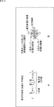
- FIG. 1 illustrates an example of filter processing as prediction processing for predicting an original image for a decoded image from a decoded image encoded and decoded (including local decoding) using a high-order prediction formula It is.
- filter processing is performed using a prediction formula consisting of only first-order terms.
- filter processing is sufficient for minute amplitude portions of pixel values that represent details of the original image degraded by encoding. Sometimes it can not be restored.
- the filtering process using the high-order prediction equation including the high-order term effectively amplifies the luminance (waveform) fluctuation slightly remaining as a portion corresponding to the detail of the original image in the decoded image.
- the original image is accurately restored, including the details of the original image.
- a product of one tap coefficient and (the pixel value of) pixels as one or more prediction taps is a term, and any polynomial is adopted if it is a polynomial including a high-order term be able to. That is, as the high-order prediction equation, for example, a polynomial consisting of only a first-order term and a second-order term, a polynomial consisting of a first-order term and a plurality of higher-order terms of two or more different orders, one or more second-order or more orders A polynomial or the like consisting of higher order terms can be employed.
- y ′ represents a predicted value of (a pixel value of) a corresponding pixel which is a pixel of the original image corresponding to a target pixel among the pixels of the decoded image.
- N1 represents the number of pixels x i as primary taps of the prediction taps, and the number of primary coefficients w i of the tap coefficients.
- w i represents the i-th primary coefficient of the tap coefficients.
- x i represents (the pixel value of) the pixel as the i-th primary tap among the prediction taps.
- N2 represents the number of pixels x j (x k ) as secondary taps of the prediction taps, and the number of secondary coefficients w j, k of the tap coefficients.
- w j, k represents the j ⁇ k second-order coefficient of the tap coefficients.
- the primary tap is represented by x i and the secondary tap is represented by x j and x k , but in the following, depending on the suffix attached to x, There is no particular distinction between primary and secondary taps. That is, for example, be any of primary tap and secondary taps, with x i, primary tap x i and the secondary tap x i, or to as a prediction tap x i, and the like. The same applies to the first-order coefficient w i and the second-order coefficient w j, k which are tap coefficients.
- the high-order prediction formula of Formula (1) is a polynomial which consists only of a first-order term and a second-order term.
- the high-order prediction formula of Expression (1) is a prediction formula as in the case where the number of candidate pixels for the primary tap is N1 and the number of candidate pixels for the secondary tap is N2.
- the number N1 ′ of primary terms of the prediction equation is equal to the number N1 of primary taps.
- the number N2 'of secondary terms of the prediction equation is expressed by equation (2).
- N2 C 2 represents the number of combinations for selecting without overlapping two from the N2.
- Filter processing for applying the high-order prediction formula to the decoded image that is, for example, the product-sum operation of the high-order prediction formula of Equation (1) is performed, and pixel values of corresponding pixels of the original image corresponding to the target pixel of the decoded image.
- a prediction tap is selected from the pixels of the decoded image.
- FIG. 1B shows an example of prediction taps, ie, for example, primary and secondary taps.
- the primary taps are 13 diamond-shaped 13 pixels centered on the target pixel, and the secondary taps are 5 diamond-shaped 5 pixels centered on the target pixel. Therefore, in FIG. 1B, the tap structure of the primary tap and the tap structure of the secondary tap are different. Further, of the 13 pixels which are primary taps, five diamond-shaped five pixels centered on the target pixel are also secondary taps.
- the high-order prediction formula can be applied to currently proposed adaptive loop filters and the like in addition to the ILF of the present technology.
- the candidate pixel for the primary tap and the candidate pixel for the secondary tap, or the tap structure of the primary tap and the tap structure of the secondary tap may be identical or different.
- the tap coefficients of the higher order prediction equation can be volumized and approximated by polynomials.
- the order of the polynomial approximating the tap coefficients can adopt the same value for the primary coefficient and the secondary coefficient among the tap coefficients, or different values Can also be adopted.
- the tap coefficients constituting the higher order prediction equation can be obtained by learning in real time in the encoding device that encodes the image, and can be transmitted to the decoding device that decodes the image.
- tap coefficients constituting the high-order prediction formula can be obtained in advance by off-line learning, and can be preset in the encoding apparatus and the decoding apparatus.
- the tap coefficients constituting the high-order prediction formula can be obtained for each of a plurality of classes.
- the filtering process can be performed using a high-order prediction formula configured by performing class classification of the pixel of interest and using the tap coefficients of the class of the pixel of interest obtained as a result.
- one class is obtained as the number of classes obtained by class classification, it is equivalent to not performing class classification.
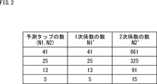
- FIG. 2 is a diagram showing the relationship between the number of prediction taps and the number of tap coefficients in the prediction equation as a whole.
- FIG. 2 shows the relationship between the number N1 of primary taps and the number N1 'of primary coefficients in the prediction formula as a whole, and the relationship between the number N2 of secondary taps and the number N2' of secondary coefficients. ing.
- the number N1 'of primary coefficients matches the number N1 of primary taps, and the number N2' of secondary coefficients exponentially increases relative to the number N2 of secondary taps.
- the filtering process can be performed using a reduction prediction equation that is a high-order prediction equation that is configured by partial terms selected from the prediction equation as a whole.
- a reduction prediction equation that is a high-order prediction equation that is configured by partial terms selected from the prediction equation as a whole.
- FIG. 3 is a diagram for explaining an example of selection of a part of terms from a prediction formula as a whole.
- a case in which all 41 candidate pixels are adopted as prediction taps and a prediction formula of only the first term of the 41 prediction taps is adopted is referred to as a reference case which is used as a reference of comparison.
- the description of the classes is appropriately omitted. That is, in the following, unless otherwise stated, the explanation for the tap coefficient and the like is the explanation for the tap coefficient and the like for each class.
- a high-order prediction formula including all 41 candidate pixels as prediction taps and including quadratic terms of the 41 prediction taps that is, for example, equation (1)
- equation (1) When adopting the whole prediction formula consisting of only the first order term and the second order term, the detail of the original image degraded by the encoding can be restored with high accuracy by the effect of the second order term that is the higher order term compared to the reference case. it can.
- the linear term of the prediction equation is 41 equal to the 41 candidate pixels
- the quadratic term of the prediction equation is 41
- 41 primary terms of the prediction equation are represented by Ax 1 , Ax 2 ,..., Ax 41 , and 861 quadratic terms of the prediction equation are , Ax 1 x 1 , Ax 1 x 2 , ..., Ax 1 x 41 , Ax 2 x 2 , Ax 2 x 3 , ..., Ax 2 x 41 , ..., Ax 41 x 41 Ru.
- the tap coefficient of one class is a linear term
- the total number of tap coefficients, and hence the amount of data, is compared with the reference case, resulting in 902 tap coefficients including 41 tap coefficients as tap coefficients and 861 tap coefficients as second order term tap coefficients. And the coding efficiency is degraded.
- the high-order prediction formula composed of a part of terms selected from the prediction formula as a whole is also referred to as a reduction prediction formula.
- the term (tap coefficients of the prediction equation) in the whole tends to have a large effect of the image quality improvement.
- the term of the pixel (prediction tap) close to the target pixel among the terms of the prediction formula as a whole is adopted as the term of the reduction prediction formula.
- the primary term of the pixel (prediction tap) close to the target pixel is selected and the reduction prediction formula is selected.
- selecting a candidate pixel close to the target pixel instead of all of the 41 candidate pixels as the primary term prediction tap corresponds to selecting a primary term of a pixel close to the target pixel.
- the number of tap coefficients (first-order coefficients) of the first-order term is smaller than 41 in the reference case.
- a quadratic term of a pixel close to a pixel of interest out of 861 quadratic terms of the whole prediction formula using 41 prediction taps is selected, and a quadratic term of the reduction prediction formula is selected.
- selecting a candidate pixel close to the target pixel instead of all of the 41 candidate pixels as the prediction tap of the secondary term corresponds to selecting a secondary term of a pixel close to the target pixel.
- the number of tap coefficients (secondary coefficients) of the quadratic term is smaller than 861 of the reference case.
- the term of the pixel close to the pixel of interest is selected and adopted as the term of the reduction prediction formula.
- the number of tap coefficients of becomes 25 the number of tap coefficients of the quadratic term becomes 15. Therefore, the number of tap coefficients in one class is 40 in total including the tap coefficients of the first-order terms and the second-order terms, reducing the data amount of the tap coefficients to almost the same amount as the reference case and encoding efficiency It can be improved. Furthermore, it is possible to accurately restore the detail of the original image which was difficult to restore by the first order coefficient (tap coefficient of the first order term) by the effect of the second order coefficient (tap coefficient of the second order term) of the reduction prediction formula it can.
- the tap coefficient of one class is set to 40 tap coefficients in total of 25 tap coefficients of the first term and 15 tap coefficients of the second term. It can be said that the use (transmission capacity) of the tap coefficient of the second term is secured by reducing the tap coefficient of the first term within the range of 41 tap coefficients.
- RD cost-based norms and PSNR-based norms for example, in filtering processing using a prediction formula as a whole, RD that exceeds the threshold value is more effective than filtering using a reduction prediction formula where a certain term is deleted from the prediction formula as a whole. If there is an improvement in cost or PSNR, the terms that are entirely deleted from the prediction formula are selected as the terms of the reduction prediction formula.
- a term whose magnitude (absolute value) of the tap coefficient is equal to or greater than a predetermined threshold value is selected as the term of the reduction prediction equation.
- the number of bits necessary to represent a tap coefficient that is, the number of significant digits when the tap coefficient is represented by a binary number (the number of significant digits A term whose) or more is a threshold is selected as a term of the reduction prediction formula.
- R1 linear terms and R2 secondary terms are selected from the whole prediction formula as the terms of the reduction prediction formula, for example, in the rule based on the number of bits necessary to represent tap coefficients
- the linear coefficient is selected from the linear terms of the prediction equation up to the top R1 number of bits necessary to represent the tap coefficients, and the tap coefficients are expressed from the quadratic terms of the prediction equation as a whole.
- the second-order terms up to the top R2 bits are selected. The same applies to RD cost based norms, PSNR based norms, and tap coefficient magnitude based norms.
- the filtering process using the prediction formula in the whole of the selection pattern for selecting the terms from the prediction formula in the whole can do.
- the filter processing using the reduction prediction formula composed of partial terms selected from the prediction formula as a whole the original image degraded by the coding while suppressing the decrease in the coding efficiency Can accurately restore the details of
- FIG. 4 is a diagram for explaining an example of the selection pattern of the quadratic term for selecting the quadratic term of the reduction prediction formula from the quadratic term of the prediction formula as a whole.
- a selection pattern of a first-order term for selecting a first-order term of the reduction prediction formula from the first-order terms of the prediction formula as a whole for example, as a selection pattern of a first-order term for selecting a first-order term of the reduction prediction formula from the first-order terms of the prediction formula as a whole.
- linear terms of pixels as prediction taps a pattern that selects a pixel close to the target pixel, that is, a linear term of 25 rhombus-shaped pixels centering on the target pixel, as a linear term of the reduction prediction formula Will be adopted in a fixed manner.
- the number of tap coefficients (primary coefficients) of the primary term is 25.
- the selection pattern of the quadratic term for example, as shown in B of FIG. 4, of the quadratic terms of the pixels as 41 diamond-shaped prediction taps, five diamond-shaped pixels centering on the pixel of interest
- a first selection pattern may be adopted in which the quadratic term of is selected as the quadratic term of the reduction prediction equation.
- the selection pattern of the quadratic term for example, as shown in C of FIG. 4, of the quadratic terms of the pixels as 41 diamond-shaped prediction taps, 13 of the diamond-like form centering on the target pixel
- a second selection pattern can be adopted in which the quadratic term of the pixel of is selected as the quadratic term of the reduction prediction equation.
- the quadratic term of one pixel of the target pixel among the quadratic terms of the pixels as 41 rhombus-shaped prediction taps is reduced
- the third selection pattern to be selected as the quadratic term of the prediction equation can be adopted.
- the total number of quadratic terms of one pixel is one, which is only a square term of (the pixel value of) that one pixel.
- the selection pattern as described above can be fixedly adopted.
- the selection of the second-order term of the reduction prediction equation among the entire selection pattern for selecting the second-order term from the prediction equation, the data of PSNR reduction amount and tap coefficient for filter processing using the entire prediction equation.
- Selection patterns that balance the amount of reduction and selection patterns that optimize (the index of) coding efficiency such as RD cost are selected as second-order selection patterns (hereinafter also referred to as adopted patterns) that are adopted in the reduction prediction formula According to the selection pattern, it is possible to select a quadratic term to be adopted in the reduction prediction formula.
- a plurality of selection patterns such as the first to third selection patterns are selected as selection patterns for selecting the quadratic term from the prediction formula as a whole.
- a selection pattern or code for balancing the reduction amount of PSNR and the reduction amount of tap coefficient data for filter processing using a prediction formula as a whole among a plurality of selection patterns prepared in advance and prepared beforehand The selection pattern that makes the conversion efficiency the best can be determined as the adopted pattern, and the quadratic term to be adopted in the reduction prediction formula can be selected according to the adopted pattern (the selected pattern determined).
- the selection pattern to be selected is fixed for each of the primary term and the secondary term, and the encoding apparatus and the decoding apparatus select according to the fixed selection pattern.
- the filtering process can be performed using a reduction prediction equation consisting of the primary term and the secondary term.
- a plurality of selection patterns are prepared in advance as selection patterns for selecting the primary term and the secondary term, and each selection pattern and its selection pattern are It is possible to associate coding information such as QP of an image that tends to improve coding efficiency when adopted. Then, in the encoding device and the decoding device, in accordance with the encoded information such as the QP of the decoded image (the original image for it), the selected pattern associated with the encoded information is determined as the adopted pattern, and the adopted pattern According to the first term and the second term to be adopted in the reduction prediction formula can be selected.
- a plurality of selection patterns can be prepared in advance as selection patterns for selecting the primary term and the secondary term. Then, in the encoding apparatus, for example, among the plurality of selection patterns, the selection pattern that makes the coding efficiency the best is determined as the adopted pattern, and the first order term and the second order term adopted in the reduction prediction formula according to the adopted pattern. Can be selected. Furthermore, in this case, the encoding apparatus transmits selection information representing the adopted pattern (selected pattern determined to) to the decoding apparatus, and the decoding apparatus reduces the information according to the adopted pattern represented by the selection information from the encoding apparatus The first order term and the second order term to be employed in the prediction equation can be selected.
- a method of preparing a plurality of selection patterns and determining an adopted pattern (a selection pattern to be taken) from among the plurality of selection patterns according to encoding information and encoding efficiency is a reduction.
- the present invention can also be applied to the case where a plurality of selection patterns are prepared for only the secondary term, with the selection pattern of the primary term of the prediction equation fixed.
- FIG. 5 is a diagram for explaining another example of the selection pattern of the quadratic term for selecting the quadratic term of the reduction prediction formula from the quadratic term of the prediction formula as a whole.
- a circle represents a pixel as a prediction tap.
- a black dot in a circle represents (the quadratic term of) the square of a pixel as a prediction tap represented by the circle, and a line connecting two different circles is a prediction represented by each of the two circles. This represents (the quadratic term of) the product of pixels as a tap.
- the selection pattern of the secondary term is shown in FIG.
- five second-order terms of squares of five five-pixel shaped rhombuses and ten second-order terms of (a product of ten combinations of two arbitrary pixels of five pixels of rhombus-shaped form) A pattern may be employed which selects a total of 15 quadratic terms.
- the number of tap coefficients (one class) is 40 in total of 25 primary coefficients and 15 secondary term tap coefficients (secondary coefficients).
- the selection pattern of the quadratic term as shown in B of FIG. 5, five quadratic terms of the square shape of five pixels of the rhombus shape as secondary taps, the attention pixel, and other four pixels A pattern may be employed which selects a total of nine quadratic terms, with four quadratic terms of the product with each.
- the number of tap coefficients is 34 in total of the 25 primary coefficients and the tap coefficients of 9 quadratic terms.
- one quadratic term of the square of the pixel of interest among the five diamond-shaped five pixels as the secondary tap and the pixel of interest It is possible to adopt a pattern which selects a total of five quadratic terms with four quadratic terms of the product of each of the other four pixels.
- the number of tap coefficients is 30 in total of the 25 primary coefficients and the tap coefficients of the 5 secondary terms.
- the selection pattern of the quadratic term as shown in D of FIG. 5, it is possible to adopt a pattern for selecting five quadratic terms of the square of five pixels of the rhombus shape as square taps. it can.
- the number of tap coefficients is 30 in total of the 25 primary coefficients and the tap coefficients of the 5 secondary terms.
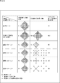
- FIG. 6 is a diagram for explaining still another example of the selection pattern of the quadratic term for selecting the quadratic term of the reduction prediction formula from the quadratic term of the prediction formula as a whole.
- FIG. 6 four selection patterns 1, 2, 3, 4 are shown as the selection terms of the secondary term.
- FIG. 6 shows the tap coefficients of the reference case and the tap coefficients of the whole prediction equation when all 41 candidate pixels of the reference case are used as the primary tap and the secondary tap.
- the number of tap coefficients (of one class) may be 41 for the first-order coefficients, it is obtained by the filter processing using a prediction formula composed of the 41 first-order coefficients Filter image, it may not be possible to sufficiently restore the details (small amplitude portion) of the original image.
- the filtering process using the prediction equation as a whole it is possible to sufficiently restore the detail of the original image in the filtered image obtained by the filtering process.
- the number of tap coefficients is 902 in total of the primary coefficient and the secondary coefficient, and the data amount of the tap coefficients is large.
- a linear term of 25 (candidate) pixels in a rhombus shape centered on the target pixel among the 41 candidate pixels in the reference case is selected as a linear term of the reduction prediction formula . Therefore, in the selection patterns 1 to 4, the number of tap coefficients (primary coefficients) of the primary term is 25.
- the number of tap coefficients is 40 in total of the primary coefficients of the 25 primary terms and the secondary coefficients of the 15 secondary terms. Less than the reference case.
- the filtering process using the reduction prediction formula of the selection pattern 1 in the filtered image obtained by the filtering process, the detail of the original image can be sufficiently restored by the effect of the quadratic term.
- the filtering process using the prediction formula can be almost performed with a small quadratic term, that is, a quadratic coefficient of a small data amount. It is possible to maintain the restoration performance of equal (close) details.
- nine square pixels in the form of a square with the pixel of interest and eight pixels adjacent to the pixel of interest are employed as secondary taps. Then, a total of nine quadratic terms of one square of the square of the pixel of interest out of the nine pixels as secondary taps and eight quadratic terms of the product of the pixel of interest and each of the other eight pixels.
- a quadratic term or nine quadratic terms of squares of 9 pixels as secondary taps are selected as quadratic terms of the reduction prediction formula.
- the number of tap coefficients is 34 in total of the primary coefficients of the 25 primary terms and the secondary coefficients of the 9 secondary terms. , Which is less than the reference case and the selection pattern 1.
- the filtering process using the reduction prediction equation of the selection pattern 2 in the filtered image obtained by the filtering process, the detail of the original image can be sufficiently restored by the effect of the quadratic term.
- the use of the secondary term (the tap coefficient) is secured by making the (first tap coefficient) of the first order term smaller than that of the reference case. Furthermore, by selecting the quadratic term of the pixel close to the pixel of interest as the quadratic term of the reduction prediction formula, the filtering process using the prediction formula can be almost performed with a small quadratic term, that is, a quadratic coefficient of a small data amount. The same detail restoration performance can be maintained.
- the selection pattern 2 is particularly effective when the original image to be restored is a pattern that spreads in the vertical and horizontal directions (having directivity in the vertical and horizontal directions).
- the selection pattern 3 five cross-shaped pixels of the pixel of interest and four pixels adjacent to the pixel of interest are adopted as secondary taps. Then, a total of five secondary terms of one square of the square of the pixel of interest out of the five pixels as secondary taps and four quadratic terms of the product of the pixel of interest and each of the other four pixels A quadratic term or five quadratic terms of the square of five pixels as secondary taps are selected as quadratic terms of the reduction prediction formula.
- the number of tap coefficients is 30 in total of the primary coefficients of the 25 primary terms and the secondary coefficients of the 5 secondary terms. , And less than the reference case, and also the selection patterns 1 and 2.
- the filtering process using the reduction prediction formula of the selection pattern 3 in the filtered image obtained by the filtering process, the detail of the original image can be sufficiently restored by the effect of the quadratic term.
- the use of the secondary term (the tap coefficient) is secured by making the primary term (the tap coefficient thereof) smaller than that of the reference case. Furthermore, by selecting the quadratic term of the pixel close to the pixel of interest as the quadratic term of the reduction prediction formula, the filtering process using the prediction formula can be almost performed with a small quadratic term, that is, a quadratic coefficient of a small data amount. The same detail restoration performance can be maintained.
- the selection pattern 3 is particularly effective when the original image to be restored is a pattern having vertical and horizontal directivity.
- the selection pattern 4 five X-shaped pixels of the pixel of interest and four pixels adjacent to the target pixel are adopted as secondary taps. Then, a total of five secondary terms of one square of the square of the pixel of interest out of the five pixels as secondary taps and four quadratic terms of the product of the pixel of interest and each of the other four pixels A quadratic term or five quadratic terms of the square of five pixels as secondary taps are selected as quadratic terms of the reduction prediction formula.
- the number of tap coefficients is 30 in total of the primary coefficients of the 25 primary terms and the secondary coefficients of the 5 secondary terms. , And less than the reference case, and also the selection patterns 1 and 2.
- the filtering process using the reduction prediction formula of the selection pattern 4 in the filtered image obtained by the filtering process, the detail of the original image can be sufficiently restored by the effect of the quadratic term.
- the use of the secondary term (the tap coefficient) is secured by making the primary term (the tap coefficient thereof) smaller than that of the reference case. Furthermore, by selecting the quadratic term of the pixel close to the pixel of interest as the quadratic term of the reduction prediction formula, the filtering process using the prediction formula can be almost performed with a small quadratic term, that is, a quadratic coefficient of a small data amount. The same detail restoration performance can be maintained.
- the selection pattern 4 is particularly effective when the original image to be restored is a pattern having diagonal directivity.
- a plurality of selection patterns for selecting the quadratic terms of pixels in the vicinity of the target pixel that easily contributes to the image quality are prepared in advance. It is possible to determine the selection pattern to be the second order selection pattern (adopted pattern) adopted in the reduction prediction formula, and transmit the selection information representing the selected pattern determined to the adopted pattern.
- the determination of an adopted pattern from among a plurality of selection patterns can be performed in frame units, sequence units, or any other unit.
- the determination of the adoption pattern it is possible to determine one selection pattern as the adoption pattern in common to all classes, or to select the one selection pattern as the adoption pattern for each class.
- FIG. 7 is a diagram for explaining a representation form of tap coefficients constituting the high-order prediction formula.
- FIG. 7 shows tap coefficients (first-order coefficients) constituting high-order prediction formula (reduction prediction formula) of selected pattern 1 using images of different properties (patterns) as learning images for learning tap coefficients.
- the maximum value and the minimum value of the values of tap coefficients obtained by performing learning for obtaining the coefficient and the secondary coefficient) are shown.
- the horizontal axis represents the order of tap coefficients
- the vertical axis represents values of tap coefficients
- serial numbers from 1 are attached in order to the 25 primary coefficients and the 15 secondary coefficients that make up the reduction prediction equation of the selection pattern 1.
- the tap coefficient is expressed by bits of a predetermined number of bits such as 8 bits.
- formats such as fixed point and floating point can be adopted, but here, in order to simplify the explanation, fixed point will be considered.
- the fixed-point representation form it is possible to adopt a representation form in which the number of bits of the integer part and the fraction part is various bits depending on the position of the decimal point in the bit string of a predetermined number of bits.
- the representation form of the tap coefficient can be determined, for example, for each of the orders of the terms constituting the high-order prediction formula (reduction prediction formula).
- the tap coefficients (the first-order coefficients) of the first-order terms have a tendency that the values largely fluctuate. Therefore, with respect to the primary coefficient, an expression form in which the number of bits is allocated to the integer part can be determined as the expression form of the primary coefficient. The number of bits to be allocated to the integer part can be determined according to the absolute value of the primary coefficient so that the accuracy of the primary coefficient can be secured.
- the tap coefficient of the quadratic term has a tendency that the absolute value of the value is small. Therefore, with regard to the secondary coefficient, an expression form in which the number of bits is allocated to the decimal part can be determined as the expression form of the secondary coefficient. The number of bits to be allocated to the fractional part can be determined according to the absolute value of the secondary coefficient so that the accuracy of the secondary coefficient can be secured.
- the secondary coefficient tends to take the value of a decimal with a large number of digits less than 1, it is possible to adopt a bit string of variable number of bits as an expression form of the tap coefficient.
- the representation format can be determined to be a bit string having a larger number of bits than the linear term.
- the position of the decimal point of the fixed-length bit string representing the tap coefficient is the tendency of the maximum value and the minimum value of the tap coefficient It can be decided beforehand at a fixed position according to
- the encoding apparatus transmits the tap coefficients in a bit string representing the tap coefficients in an expression format in which the position of the decimal point is determined in advance at a fixed position. Then, the decoding device treats the bit string representing the tap coefficient of each order term (linear term and quadratic term) from the encoding device as a bit string of expression format in which the position of the decimal point is determined in advance at a fixed position. Processing, that is, calculation of a high-order prediction formula (reduction prediction formula) is performed.
- the representation form is determined according to the magnitude of the absolute value of the primary coefficient and the secondary coefficient for each frame, sequence, etc. That is, the position of the decimal point of the fixed length bit string representing the tap coefficient can be determined according to the tendency of the maximum value and the minimum value of the tap coefficient.
- the encoding apparatus transmits the primary coefficient and the secondary coefficient in the expression format of the determined decimal point position, and transmits format information representing the expression format for each of the primary coefficient and the secondary coefficient.
- the decoding device specifies the representation form of the bit string representing the tap coefficient of each order term (primary term and secondary term) from the encoding device from the format information from the encoding device, and the bit string representing the tap coefficient , And treating as a bit string of the expression format specified from the format information, the filter processing, that is, the calculation of the high-order prediction equation (reduction prediction equation) is performed.
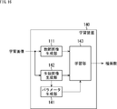
- FIG. 8 is a block diagram showing an outline of an embodiment of an image processing system to which the present technology is applied.
- the image processing system includes an encoding device 11 and a decoding device 12.
- the encoding device 11 includes an encoding unit 21, a local decoding unit 23, and a filter unit 24.
- the encoding unit 21 is supplied with the original image (data) that is the image to be encoded, and the filter image from the filter unit 24.
- the encoding unit 21 (predictive) encodes the original image using the filter image from the filter unit 24, and supplies encoded data obtained by the encoding to the local decoding unit 23.
- the encoding unit 21 subtracts the predicted image of the original image obtained by performing motion compensation of the filter image from the filter unit 24 from the original image, and encodes the residual obtained as a result.
- the encoding unit 21 generates and transmits (transmits) an encoded bit stream including the encoded data and the filter information supplied from the filter unit 24.
- the filter information includes, as necessary, tap coefficients constituting the high-order prediction formula (reduction prediction formula), and further, selection information and format information.
- the encoded bit stream generated by the encoding unit 21 is a bit stream including tap coefficients, selection information, and format information as needed in addition to the encoded data.
- the local decoding unit 23 is supplied with the encoded data from the encoding unit 21, and is also supplied with the filter image from the filter unit 24.
- the local decoding unit 23 performs local decoding of the encoded data from the encoding unit 21 using the filter image from the filter unit 24, and supplies the (local) decoded image obtained as a result to the filter unit 24.
- the local decoding unit 23 decodes the encoded data from the encoding unit 21 into a residual, and performs motion compensation of the filter image from the filter unit 24 on the residual to obtain a predicted image of the original image obtained.
- the addition generates a decoded image obtained by decoding the original image.
- the filter unit 24 performs a filter process of applying a high-order prediction formula (reduction prediction formula) to the decoded image from the local decoding unit 23, generates a filter image, and supplies the filter image to the encoding unit 21 and the local decoding unit 23. Do.
- the filter unit 24 when performing the filter processing, performs learning for obtaining tap coefficients that constitute a high-order prediction formula (reduction prediction formula) as necessary, and determines an adopted pattern and an expression form of the tap coefficients. Do. Then, the filter unit 24 supplies the tap coefficient, the selection information indicating the adopted pattern, and the format information indicating the expression format of the tap coefficient to the encoding unit 21 as filter information related to the filter process.
- the decoding device 12 includes a parsing unit 31, a decoding unit 32, and a filter unit 33.
- the parsing unit 31 receives and parses the encoded bit stream transmitted by the encoding device 11, extracts (gets) filter information included in the encoded bit stream, and supplies the filter information to the filter unit 33. Furthermore, the parsing unit 31 supplies the encoded data included in the encoded bit stream to the decoding unit 32.
- the decoding unit 32 is supplied with the encoded data from the parsing unit 31 and also with the filter image from the filter unit 33.
- the decoding unit 32 decodes the encoded data from the parsing unit 31 using the filter image from the filter unit 33, and supplies the decoded image obtained as a result to the filter unit 33.
- the decoding unit 32 decodes the encoded data from the perspective unit 31 into a residual, and performs motion compensation of the filter image from the filter unit 33 on the residual.
- a predicted image of the original image is added to generate a decoded image obtained by decoding the original image.
- the filter unit 33 performs filter processing to apply a high-order prediction formula (reduction prediction formula) to the decoded image from the decoder 32, generates a filter image, and supplies the filter image to the decoder 32. Do.
- the filter unit 33 uses the filter information from the perspective unit 31 as necessary when performing the filter process. Further, the filter unit 33 supplies the filter image obtained (generated) by the filter process to the decoding unit 32, and outputs the original image as a restored image.
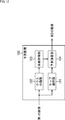
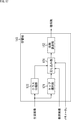
- FIG. 9 is a block diagram showing an outline of a configuration example of the filter units 24 and 33 of FIG.
- the filter unit 24 includes a class classification unit 41, a learning unit 42, a DB (database) 43, a determination unit 44, a DB 45, and a prediction unit 46.
- the original image is supplied to the filter unit 24 as well as the decoded image from the local decoding unit 23 (FIG. 8).
- the decoded image is supplied to the class classification unit 41, the learning unit 42, the determination unit 44, and the prediction unit 46, and the original image is supplied to the learning unit 42 and the determination unit 44.
- the class classification unit 41 sequentially selects the pixels of the decoded image supplied thereto as the pixel of interest. Furthermore, the class classification unit 41 classifies the pixel of interest, and supplies the class of the pixel of interest obtained as a result to the learning unit 42, the determination unit 44, and the prediction unit 46.
- the learning unit 42 uses the original image and the decoded image supplied thereto as a learning image for learning for determining tap coefficients, and selects a plurality of selection patterns, ie, for example, each of the selection patterns 1 to 4 in FIG. A learning is performed for each class to obtain primary and secondary coefficients that are tap coefficients that constitute a pattern reduction prediction equation.
- the learning unit 42 performs learning for each frame (picture) of the original image and the decoded image, and supplies, to the DB 43, tap coefficients for each class obtained for each of a plurality of selection patterns by the learning.
- the DB 43 temporarily stores the tap coefficient for each class for each of the plurality of selection patterns supplied from the learning unit 42.
- the determination unit 44 expresses an expression form (hereinafter also referred to as a best expression form) that optimizes the coding efficiency for each of the primary coefficient and secondary coefficient that are tap coefficients for each class stored in the DB 43. To determine).
- an expression form hereinafter also referred to as a best expression form
- the determination unit 44 adopts a selection pattern that optimizes the coding efficiency when filtering processing is performed to apply a reduction prediction equation including tap coefficients in the best representation format to each selection pattern.
- the pattern is determined (selected), and the tap coefficient for each class for the adopted pattern (selected pattern determined) is supplied to the DB 45.
- the determination unit 44 outputs form information representing the best expression form of each of the primary coefficient and secondary coefficient which are tap coefficients for the adopted pattern, and selection information representing the adopted pattern.
- the format information and the selection information output from the determination unit 44 are supplied to the prediction unit 46 and included in the encoded bit stream as filter information in the encoding unit 21 (FIG. 8) and transmitted to the decoding device 12 Ru.
- the determination unit 44 applies, to the decoded image, a reduction prediction equation configured of tap coefficients for each class stored in the DB 43 for each selection pattern, as needed.
- the same filtering process as that of the original image is performed, and the original image is used together with the resulting filtered image to determine the coding efficiency such as the RD cost.
- the DB 45 temporarily stores the tap coefficient for each class for the adoption pattern supplied from the determination unit 44.
- the tap coefficients for each class for the adopted pattern stored in the DB 45 are included in the encoded bit stream as filter information in the encoding unit 21 (FIG. 8) and transmitted to the decoding device 12.
- the prediction unit 46 applies, to the decoded image, a reduction prediction equation including tap coefficients of the class of the pixel of interest from the class classification unit 41 among tap coefficients for each class for the adopted pattern stored in the DB 45.
- Filter processing as prediction processing (high-order prediction expression using reduction prediction expression, so to speak, high-order prediction processing), and the filter image obtained as a result thereof is encoded by the encoding unit 21 and the local decoding unit 23 (FIG. Supply to 8).
- the prediction unit 46 specifies the expression format (best expression format) of the tap coefficient (each of the primary coefficient and the secondary coefficient) from the format information from the determination unit 44. Further, the prediction unit 46 specifies the adopted pattern of the reduction polynomial from the selection information from the determination unit 44, and from the adopted pattern, the term constituting the reduction polynomial, and as a prediction tap used for the calculation of the reduction polynomial. Identify pixels of the decoded image.
- the prediction unit 46 performs filter processing for applying the reduction prediction formula of the adopted pattern, which is composed of the tap coefficients of the class of the target pixel in the best representation format, to the decoded image, that is, prediction as calculation of the reduction prediction formula.
- a product-sum operation is performed on (the pixel values of) the pixels of the decoded image as taps and the tap coefficients to obtain a filter image.
- the calculation according to the best expression form of the tap coefficient and the expression form of the pixel value of the decoded image is performed. That is, for example, when the pixel value and tap coefficient of the decoded image are represented by 10 bits, the pixel value of the decoded image is an integer type, and the tap coefficient is fixed point having a 9-bit fractional part, decoding in filter processing
- the product of the bit string representing the pixel value of the decoded image and the bit string representing the tap coefficient is determined, and then the bit string representing the product is shifted to the right by 9 bits , Divided by 512.
- the filter unit 33 includes a classification unit 51 and a prediction unit 52.
- Filter information is supplied to the filter unit 33 from the perspective unit 31 (FIG. 8), and a decoded image is supplied from the decoding unit 32 (FIG. 8).
- the class classification section 51 sequentially selects the pixels of the decoded image supplied thereto as the pixel of interest. Furthermore, the class classification unit 51 classifies the pixel of interest and supplies the class of the pixel of interest obtained as a result to the prediction unit 52.
- the prediction unit 52 applies, to the decoded image, a reduction prediction equation including tap coefficients of the class of the pixel of interest from the class classification unit 51 among tap coefficients for each class for the adopted pattern included in the filter information. Then, filter processing as prediction processing is performed, and the filter image obtained as a result is supplied to the decoding unit 32 (FIG. 8).
- the prediction unit 52 specifies the expression format (best expression format) of the tap coefficient (each of the primary coefficient and the secondary coefficient) from the format information included in the filter information. Further, the prediction unit 52 specifies the adopted pattern of the reduction polynomial from the selection information included in the filter information, and from the adopted pattern, the term constituting the reduction polynomial, and as a prediction tap used for the calculation of the reduction polynomial. Identify pixels of the decoded image.
- the prediction unit 52 performs filter processing for applying the reduction prediction formula of the adopted pattern, which is composed of the tap coefficients of the class of the target pixel in the best expression format, to the decoded image, that is, prediction as calculation of the reduction prediction formula.
- a product-sum operation is performed on (the pixel values of) the pixels of the decoded image as taps and the tap coefficients to obtain a filter image.
- FIG. 10 is a flowchart for explaining the outline of the encoding process of the encoding device 11 of FIG.
- the process according to the flowchart of FIG. 10 is performed, for example, on a frame basis.
- step S11 the encoding unit 21 (FIG. 8) (predictive) encodes the original image using the filter image from the filter unit 24, and uses the local decoding unit 23 for the encoded data obtained by the encoding. After supplying, the process proceeds to step S12.
- step S12 the local decoding unit 23 performs local decoding of the encoded data from the encoding unit 21 using the filter image from the filter unit 24, and the (locally) decoded image obtained as a result thereof is processed by the filter unit 24. , And the process proceeds to step S13.
- step S13 in the filter unit 24, the class classification unit 41 (FIG. 9) sequentially selects the pixels of the decoded image from the local decoding unit 23 as the pixel of interest. Furthermore, the class classification unit 41 classifies the pixel of interest, supplies the class of the pixel of interest obtained as a result to the learning unit 42, the determination unit 44, and the prediction unit 46, and the process proceeds to step S14. move on.
- step S14 the learning unit 42 uses one frame of the decoded image from the local decoding unit 23 and one frame of the original image for the frame of the decoded image as a learning image for learning for obtaining tap coefficients, and a plurality of selection patterns For each class, learning is performed for each class to obtain a primary coefficient and a secondary coefficient that are tap coefficients constituting the reduction prediction formula of the selected pattern.
- the learning unit 42 stores the tap coefficient for each class obtained for each of the plurality of selection patterns by learning in the DB 43, and the process proceeds from step S14 to step S15.
- step S15 the determination unit 44 is, for each selected pattern, a best expression that is an expression format that optimizes the coding efficiency for each of the primary coefficient and the secondary coefficient that are tap coefficients for each class stored in the DB 43.
- the format is determined, and the process proceeds to step S16.
- step S16 the determination unit 44 selects, for each selection pattern, a selection pattern that maximizes the coding efficiency when the reduction prediction formula configured of tap coefficients in the best representation format is applied to the decoded image. Is selected (selected) as an adopted pattern, and the tap coefficient for each class for the adopted pattern (selected pattern determined) is stored in the DB 45. The tap coefficients for each class for the adopted pattern stored in the DB 45 are supplied to the encoding unit 21 as filter information.
- the determination unit 44 uses, as filter information, the format information indicating the best expression format of each of the primary coefficient and the secondary coefficient that are tap coefficients for the adopted pattern, and the selection information indicating the adopted pattern. And the prediction unit 46, and the process proceeds from step S16 to step S17.
- step S17 of the tap coefficients for each class of the adopted pattern stored in the DB 45, the prediction unit 46 locally uses a reduction prediction formula configured of tap coefficients of the class of the pixel of interest from the class classification unit 41. It applies to the decoded image from the decoding unit 23 and performs filter processing as prediction processing.
- the prediction unit 46 specifies the expression format (best expression format) of the tap coefficient (each of the primary coefficient and the secondary coefficient) from the format information from the determination unit 44. Further, the prediction unit 46 specifies the adopted pattern of the reduction polynomial from the selection information from the determination unit 44.
- the prediction unit 46 performs filter processing for applying a reduction prediction formula of the adopted pattern, which is composed of tap coefficients of the class of the target pixel in the best expression format, to the decoded image, and obtains a filter image.
- the prediction unit 46 supplies the filter image obtained as a result of the filtering process to the encoding unit 21 and the local decoding unit 23, and the process proceeds from step S17 to step S18.
- the filter image supplied from the prediction unit 46 to the encoding unit 21 and the local decoding unit 23 in step S17 is used, for example, in the processes of steps S11 and S12 performed on the next frame of the decoded image.
- step S18 the encoding unit 21 generates and transmits an encoded bit stream including encoded data and filter information from the filter unit 24, that is, selection information, format information, and tap coefficients for each class. Do.
- one selection pattern may be determined as the adoption pattern in common to all classes, or one selection pattern may be determined as the adoption pattern for each class. Can.
- the number of selection information and format information is the number (total number) times of the number of classes in the case where one selection pattern is determined as the adopted pattern in common to all classes.
- the prediction unit 46 specifies the tap coefficient representation form (best representation form) for each class in the filtering process performed in step S17. And identifying the adopted pattern of the reduction polynomial, and from the adopted pattern, identify the terms constituting the reduction polynomial and, consequently, the pixels of the decoded image as the prediction taps used for the calculation of the reduction polynomial.
- FIG. 11 is a flowchart illustrating an outline of the decoding process of the decoding device 12 of FIG.
- the process according to the flowchart of FIG. 11 is performed, for example, in units of frames, similarly to the encoding process of FIG.
- step S21 the parsing unit 31 (FIG. 8) extracts the filter information included in the encoded bit stream by receiving the encoded bit stream transmitted from the encoding device 11 and performing parsing. ) To the filter unit 33. Furthermore, the parsing unit 31 supplies the encoded data included in the encoded bit stream to the decoding unit 32, and the process proceeds from step S21 to step S22.
- step S22 the decoding unit 32 decodes the encoded data from the perspective unit 31 using the filter image from the filter unit 33, supplies the decoded image obtained as a result to the filter unit 33, and performs processing. The process proceeds to step S23.
- step S23 in the filter unit 33, the class classification unit 51 (FIG. 9) sequentially selects the pixels of the decoded image from the decoding unit 32 as the pixel of interest. Furthermore, the class classification unit 51 classifies the pixel of interest, supplies the class of the pixel of interest obtained as a result to the prediction unit 52, and the process proceeds to step S24.
- step S24 of the tap coefficients for each class of the adopted pattern included in the filter information from the perspective unit 31, the prediction unit 52 is configured to be configured with the tap coefficients of the class of the pixel of interest from the class classification unit 51.
- the prediction equation is applied to the decoded image from the decoding unit 32, and filter processing as prediction processing is performed to obtain (generate) a filter image.
- the prediction unit 52 specifies the expression format (best expression format) of the tap coefficient (each of the primary coefficient and the secondary coefficient) from the format information included in the filter information. Further, the prediction unit 52 specifies an adopted pattern of the reduction polynomial from the selection information included in the filter information.
- the prediction unit 52 performs filter processing for applying a reduction prediction formula of the adopted pattern, which is composed of tap coefficients of the class of the target pixel in the best expression format, to the decoded image, and obtains a filter image.
- the filter image obtained as a result of the filtering process in the prediction unit 52 is supplied to the decoding unit 32 (FIG. 8) and is output as a restored image obtained by restoring the original image.
- the filter image supplied from the prediction unit 52 to the decoding unit 32 in step S24 is used, for example, in the process of step S22 performed on the next frame of the decoded image.
- Class classification prediction processing for an image performs class classification using a first image which is an image of a class classification prediction processing target, and tap coefficients of the class obtained as a result of the class classification and the first image Filter processing as prediction processing using a prediction formula that performs product-sum operation with (the pixel value of) pixels of the pixel (filtering processing), and the prediction value of the second image is determined (generated) by such filter processing .
- the first image is a decoded image (including a local decoded image)
- the second image is an original image.
- FIG. 12 is a block diagram showing a first configuration example of a prediction device that performs class classification prediction processing.
- the tap coefficient of the class obtained by classifying the target pixel of interest in the first image into any one of a plurality of classes, and prediction with respect to the target pixel The product-sum operation as the calculation of the prediction formula using the pixel value of the first image pixel selected as the tap determines the predicted value of the pixel value of the corresponding pixel of the second image corresponding to the target pixel .
- FIG. 12 shows a configuration example of a prediction device that performs class classification prediction processing.
- the prediction device 100 includes a tap selection unit 101, a class classification unit 102, a coefficient acquisition unit 103, and a prediction calculation unit 104.
- the prediction apparatus 100 is supplied with the first image.
- the first image supplied to the prediction device 100 is supplied to the tap selection unit 101 and the class classification unit 102.
- the tap selection unit 101 sequentially selects the pixels forming the first image as the target pixel. Furthermore, the tap selection unit 101 predicts some of (pixel values of) pixels constituting the first image used to predict (the pixel value of) the corresponding pixel of the second image corresponding to the target pixel. Select as a tap.
- the tap selection unit 101 selects, as prediction taps, a plurality of pixels of the first image located at a position spatially or temporally close to the position of space-time of the pixel of interest. Supply.
- the class classification unit 102 classifies the pixel of interest into one of several classes according to a certain rule, and supplies the class of the pixel of interest obtained as a result to the coefficient acquisition unit 103. .
- the class classification unit 102 selects, for example, some of (the pixel values of) the pixels constituting the first image used to perform the class classification for the pixel of interest as class taps. For example, the class classification unit 102 selects a class tap in the same manner as the tap selection unit 101 selects a prediction tap.
- the prediction tap and the class tap may have the same tap structure, or may have different tap structures.
- the class classification unit 102 classifies the pixel of interest using, for example, a class tap, and supplies the class of the pixel of interest obtained as a result to the coefficient acquisition unit 103.
- the class classification unit 102 obtains the image feature amount of the pixel of interest using a class tap. Furthermore, the class classification unit 102 classifies the pixel of interest according to the image feature amount of the pixel of interest, and supplies the class obtained as a result to the coefficient acquisition unit 103.
- ADRC Adaptive Dynamic Range Coding
- ADRC code represents a waveform pattern as an image feature of a small area including a target pixel.
- the pixel value of each pixel as a class tap is requantized into L bits. That is, the pixel value of each pixel as a class tap, the minimum value MIN is subtracted, and the subtracted value is divided by DR / 2 L (requantization). Then, a bit string obtained by arranging the pixel values of each pixel of L bits as class taps, which are obtained as described above, in a predetermined order is output as an ADRC code.
- the pixel value of each pixel as the class tap is divided by the average value of the maximum value MAX and the minimum value MIN (rounded down to the decimal point), As a result, the pixel value of each pixel is made 1 bit (binarized). Then, a bit string in which the 1-bit pixel values are arranged in a predetermined order is output as an ADRC code.
- the value represented by such an ADRC code represents a class.
- DiffMax Dynamic Range
- DR Dynamic Range
- classification can be performed using the quantization parameter QP of the pixel of interest and other coding information. That is, class classification can be performed by, for example, threshold processing of coding information.
- the coefficient acquisition unit 103 stores the tap coefficient for each class obtained by learning, and further acquires the tap coefficient of the class of the target pixel supplied from the class classification unit 102 among the stored tap coefficients. Furthermore, the coefficient acquisition unit 103 supplies the tap coefficient of the class of the pixel of interest to the prediction calculation unit 104.
- the prediction calculation unit 104 uses the prediction tap from the tap selection unit 101 and the tap coefficient supplied from the coefficient acquisition unit 103 to select the pixel value of the pixel (corresponding pixel) of the second image corresponding to the target pixel. Filter processing is performed as prediction processing which is product-sum operation of a prediction formula for obtaining a prediction value of a true value. Thereby, the prediction calculation unit 104 obtains (predicted value of) the pixel value of the corresponding pixel, that is, (predicted value of) the pixel value of the pixel constituting the second image, and outputs it.
- FIG. 13 is a block diagram showing a configuration example of a learning device that performs learning of tap coefficients stored in the coefficient acquisition unit 103.
- the decoded image is adopted as the first image
- the original image for the decoded image is adopted as the second image
- prediction taps and tap coefficients selected from the first image It is assumed that the pixel value of the pixel of the original image as the second image (hereinafter, also referred to as a second pixel) is predicted by the filter process as the prediction process which is the product-sum operation of the prediction equation consisting of only the first order terms.
- the pixel value y of the second pixel as the corresponding pixel of the second image corresponding to the target pixel is obtained according to the following prediction equation.
- x n is the pixel of the n-th of the first image as a prediction tap of the pixel of interest (hereinafter, also referred to as a first pixel) represents the pixel values of
- w n is the n th Represents the tap coefficient (n-th tap coefficient) of the first-order term of.
- the prediction equation of equation (3) is composed of N terms (first order terms).
- the pixel value y of the second pixel is determined not by the prediction formula consisting only of the first-order term of Formula (3) but by a high-order prediction formula including second-order or higher order terms.
- x n, k represents the n-th 1st pixel as a prediction tap with respect to the 2nd pixel of the k-th sample as a corresponding
- the tap coefficient w n for which the prediction error e k in equation (5) (or equation (4)) is 0 is optimal for predicting the second pixel, but for all the second pixels, Determining such tap coefficients w n is generally difficult.
- the optimum tap coefficient w n is the sum E of square errors represented by the following equation It can be determined by minimizing statistical error).
- K is a second pixel y k as the corresponding pixel
- the first pixel x 1, k of the prediction tap for the second pixel y k, x 2, k, ⁇ .., X N, k represents the number of samples in the set (the number of samples for learning).
- Equation (7) The minimum value of the sum E of square errors of Equation (6) (minimum value), as shown in Equation (7), given a material obtained by partially differentiating the sum E with the tap coefficient w n by w n to 0.
- equation (9) can be expressed by the normal equation shown in the equation (10).
- Equation (10) can be solved for the tap coefficient w n by using, for example, the sweep method (Gauss-Jordan elimination method) or the like.
- FIG. 13 shows a configuration example of a learning device that performs learning for obtaining a tap coefficient w n by setting and solving the normal equation of Equation (10).
- the learning device 110 includes a teacher image generation unit 111, a student image generation unit 112, and a learning unit 113.
- the teacher image generation unit 111 is a teacher image as teacher data as a teacher (true value) of learning of tap coefficients, that is, a teacher as a mapping destination of a mapping as calculation of a prediction equation according to equation (3).
- an image an image corresponding to a second image is generated and supplied to the learning unit 113.
- the teacher image generation unit 111 supplies the learning image as it is to the learning unit 113 as a teacher image.
- the student image generation unit 112 uses the learning image as a student image serving as student data serving as a student for learning tap coefficients, that is, a student image serving as a mapping source of a mapping serving as a calculation of a prediction equation according to equation (3).
- An image corresponding to one image is generated and supplied to the learning unit 113.
- the student image generation unit 112 generates a decoded image by, for example, encoding and locally decoding the learning image in the same manner as the encoding device 11, and the learning unit 113 uses this decoded image as a student image.
- the learning unit 113 sequentially sets the pixels forming the student image from the student image generation unit 112 as a target pixel, and for the target pixel, a pixel having the same tap structure as the tap selection unit 101 in FIG. 12 selects. , Select from the student image as a prediction tap. Furthermore, the learning unit 113 uses the corresponding pixel forming the teacher image corresponding to the target pixel and the prediction tap of the target pixel, and solves the normal equation of equation (10) for each class to solve the class. Find the tap coefficient for each.
- FIG. 14 is a block diagram showing a configuration example of the learning unit 113 of FIG.
- the learning unit 113 includes a tap selection unit 121, a class classification unit 122, an addition unit 123, and a coefficient calculation unit 124.
- the student image is supplied to the tap selection unit 121 and the class classification unit 122, and the teacher image is supplied to the adding unit 123.
- the tap selection unit 121 sequentially selects the pixels forming the student image as the target pixel, and supplies information representing the target pixel to the necessary blocks.
- the tap selection unit 121 selects, from the pixels forming the student image for the pixel of interest, the same pixel as selected by the tap selection unit 101 of FIG.
- the prediction tap having the same tap structure as obtained is obtained and supplied to the adding unit 123.
- the class classification unit 122 classifies, with the student image, the same class as the class classification unit 102 in FIG. 12 with respect to the pixel of interest, and outputs the class of the pixel of interest obtained as a result to the adding unit 123.
- the adding unit 123 acquires (the pixel value of) the corresponding pixel corresponding to the target pixel from the pixels forming the teacher image, and as a prediction tap for the corresponding pixel and the target pixel supplied from the tap selection unit 121.
- the addition for the (pixel value of) the pixel of the student image is performed for each class of the target pixel supplied from the class classification unit 122.
- the adding unit 123 is supplied with the corresponding pixel y k of the teacher image, the prediction tap x n, k of the target pixel as the student image, and the class of the target pixel.
- the adder 123 uses the pixel x n, k of the student image as a prediction tap for each class of the pixel of interest, and multiplies the pixels of the student image in the matrix on the left side of equation (10) (x n, k x An operation corresponding to n ', k ) and the summarization ( ⁇ ) is performed.
- the adding unit 123 uses the prediction tap x n, k and the pixel y k of the teacher image for each class of the pixel of interest again, and uses the prediction tap x n, k and the teacher in the vector on the right side of Equation (10) multiplication (x n, k y k) of a pixel y k of the image and the calculation corresponding to summation (sigma) performed.
- the adding unit 123 calculates the component ( ⁇ x n, k x n ′, k ) of the matrix on the left side in equation (10) obtained for the corresponding pixel of the teacher image corresponding to the target pixel last time and the vector on the right side.
- Component ( ⁇ x n, k y k ) is stored in its built-in memory (not shown), and its matrix component ( ⁇ ⁇ ⁇ ⁇ ⁇ ⁇ ⁇ x n , k x n ', k ) or vector component ( ⁇ x n, For k y k ), for the corresponding pixel y k + 1 corresponding to the new pixel of interest, the corresponding component x calculated using the corresponding pixel y k + 1 and the prediction tap x n, k + 1 Add n, k + 1 x n ', k + 1 or x n, k + 1 y k + 1 (perform the addition represented by the summarization of equation (10)).
- the adding-in unit 123 performs, for example, the above-mentioned addition with all the pixels of the student image as the target pixel, thereby formulating the normal equation shown in the equation (10) for each class. , To the coefficient calculation unit 124.
- the coefficient calculation unit 124 solves the normal equation for each class supplied from the adding unit 123 to obtain and output an optimal tap coefficient w n for each class.
- FIG. 15 is a block diagram showing a second configuration example of a prediction device that performs class classification prediction processing.
- the prediction device 130 includes a tap selection unit 101, a class classification unit 102, a prediction calculation unit 104, and a coefficient acquisition unit 131.
- the prediction device 130 of FIG. 15 is common to the case of FIG. 12 in that the tap selection unit 101, the class classification unit 102, and the prediction operation unit 104 are included.
- FIG. 15 is different from the case of FIG. 12 in that a coefficient acquisition unit 131 is provided instead of the coefficient acquisition unit 103.
- the coefficient acquisition unit 131 stores a seed coefficient described later. Furthermore, a parameter z is supplied to the coefficient acquisition unit 131 from the outside.
- the coefficient acquisition unit 131 generates and stores tap coefficients for each class corresponding to the parameter z from the seed coefficients, and acquires the tap coefficients of the class from the class classification unit 102 from the tap coefficients for each class. , Supply to the prediction calculation unit 104.
- FIG. 16 is a block diagram illustrating a configuration example of a learning device that performs learning for obtaining the seed coefficient stored in the coefficient acquisition unit 131.
- volume coefficients ie, seed coefficients that are coefficients constituting the polynomial when tap coefficients constituting the prediction equation are approximated by a polynomial, are determined for each class, for example.
- the tap coefficient w n is approximated by the following polynomial using the seed coefficient and the parameter z.
- Equation (11) ⁇ m, n represents the m-th seed coefficient used to obtain the n-th tap coefficient w n .
- the tap coefficient w n is obtained using M seed coefficients ⁇ 1, n 2, ⁇ 2 n ,..., ⁇ M, n .
- the equation for obtaining the tap coefficient w n from the seed coefficient ⁇ m, n and the parameter z is not limited to the equation (11).
- the tap coefficient w n is determined by a linear primary expression of the seed coefficient ⁇ m, n and the variable t m .
- x n, k represents the n-th 1st pixel as a prediction tap with respect to the 2nd pixel of the k-th sample as a corresponding
- the seed coefficient ⁇ m, n which sets the prediction error e k of equation (16) to 0 is optimal for predicting the second pixel, but such seed coefficients for all the second pixels Finding ⁇ m, n is generally difficult.
- the least square method is adopted as a standard indicating that the seed coefficient ⁇ m, n is optimum, for example, the optimum seed coefficient ⁇ m, n is a square error represented by the following equation This can be obtained by minimizing the sum E of.
- K is a second pixel y k as the corresponding pixel
- the first pixel x 1, k of the prediction tap for the second pixel y k, x 2, k, ⁇ .., X N, k represents the number of samples in the set (the number of samples for learning).
- equation (19) can be expressed by the normal equation shown in equation (22) using Xi , p, j, q and Yi , p .
- Equation (22) can be solved for the seed coefficient ⁇ m, n by using, for example, the sweep method (Gauss-Jordan elimination method) or the like.
- the obtained seed coefficient ⁇ m, n for each class is stored in the coefficient acquisition unit 131.
- a tap coefficient w n for each class is generated according to equation (11) from the seed coefficient ⁇ m, n and the parameter z given from the outside, and in the prediction operation unit 104
- the pixel value of the second pixel is calculated by calculating the equation (3) using the coefficient w n and the first pixel x n as a prediction tap for the pixel of interest The (predicted value of) is obtained.
- FIG. 16 is a diagram showing a configuration example of a learning device that performs learning for obtaining the seed coefficient ⁇ m, n for each class by solving the normal equation of Equation (22) by class.
- the learning device 140 includes a teacher image generation unit 111, a parameter generation unit 141, a student image generation unit 142, and a learning unit 143.
- the learning device 140 of FIG. 16 is common to the learning device 110 of FIG. 13 in that the training image generating unit 111 is included.
- the learning device 140 in FIG. 16 is different from the learning device 110 in FIG. 13 in that the parameter generation unit 141 is newly included. Further, the learning device 140 of FIG. 16 is different from the learning device 110 of FIG. 13 in that a student image generating unit 142 and a learning unit 143 are provided instead of the student image generating unit 112 and the learning unit 113. It is different.
- the parameter generation unit 141 generates a student image from the learning image in the student image generation unit 142, generates a parameter z according to the student image, and supplies the parameter z to the learning unit 143.
- the parameter generation unit 141 may, for example, For example, a value according to the movement amount of the full screen movement of the student image is generated as the parameter z as the image feature amount of the student image generated in step b.
- the parameter generation unit 141 may, for example, calculate (a value corresponding to) the quantization parameter QP used for encoding the teacher image (the learning image) performed in the generation of the student image in the student image generation unit 142. Generate as parameter z.
- the parameter generation unit 141 generates a value according to the S / N of the student image generated by the student image generation unit 142 as the parameter z.
- the parameter generation unit 141 generates a parameter z for (the pixels of) the student image generated by the student image generation unit 142.
- a value corresponding to the movement amount of the entire screen movement of the student image and the quantization parameter QP used for encoding the teacher image performed in the generation of the student image are Can be generated as parameters z and z '.
- the parameter generation unit 141 can generate a plurality of parameters other than two, that is, three or more parameters.
- the two parameters z and z' are externally given in the coefficient acquisition unit 103 of FIG. 15, and the two parameters are generated.
- Tap coefficients are generated using z and z 'and the seed coefficients.
- the seed coefficient it is possible to generate tap coefficients using one parameter z, two parameters z and z ′, and three or more parameters.
- the determination can be made, that is, the tap coefficients can be approximated by a polynomial using a plurality of parameters.
- the description will be made using a seed coefficient that generates a tap coefficient using one parameter z as an example.
- the student image generation unit 142 is supplied with the same learning image as that supplied to the teacher image generation unit 111.
- the student image generation unit 142 generates a student image from the learning image as in the case of the student image generation unit 112 in FIG. 13 and supplies the student image as a student image to the learning unit 143. That is, the student image generation unit 142 generates a decoded image by, for example, encoding and locally decoding the learning image in the same manner as the encoding device 11, and using the decoded image as the student image, the learning unit 113 Supply.
- the processing of the student image generation unit 142 is referred to by the parameter generation unit 141.
- the learning unit 143 obtains and outputs a seed coefficient for each class using the teacher image from the teacher image generation unit 111, the parameter z from the parameter generation unit 141, and the student image from the student image generation unit 142.
- FIG. 17 is a block diagram showing a configuration example of the learning unit 143 of FIG.
- the learning unit 143 includes a tap selection unit 121, a class classification unit 122, an addition unit 151, and a coefficient calculation unit 152.
- the learning unit 143 in FIG. 17 is common to the learning unit 113 in FIG. 14 in that the tap selecting unit 121 and the class sorting unit 122 are included.
- the learning unit 143 is different from the learning unit 113 in FIG. 14 in that the learning unit 143 includes an adding unit 151 and a coefficient calculating unit 152 instead of the adding unit 123 and the coefficient calculating unit 124.
- the tap selection unit 121 selects a prediction tap from the student image corresponding to the parameter z generated by the parameter generation unit 141 in FIG. 16 and supplies the prediction tap to the adding unit 151.
- the adding unit 151 obtains a corresponding pixel corresponding to the target pixel from the teacher image from the teacher image generation unit 111 in FIG. 16, and uses the corresponding pixel as a prediction tap for the target pixel supplied from the tap selection unit 121.
- the addition of the pixel (student pixel) of the student image and the parameter z to (the target pixel of) the student image is performed for each class supplied from the class classification unit 122.
- the adding unit 151 includes the pixel (teacher pixel) y k of the teacher image corresponding to the target pixel, the prediction tap x i, k (x j, k ) for the target pixel output by the tap selection unit 121, and The class of the pixel of interest output from the class classification unit 122 is supplied, and the parameter z for (the student image including) the pixel of interest is supplied from the parameter generation unit 141.
- the adding unit 151 uses the prediction tap (student image) x i, k (x j, k ) and the parameter z for each class supplied from the class classification unit 122, in the matrix on the left side of Expression (22), component X i, which is defined by equation (20), p, j, multiplication of the student pixel and the parameter z for determining the q (x i, k t p x j, k t q) and, on the summation (sigma) Perform the corresponding operation.
- t p of formula (20), according to equation (12) is calculated from the parameter z. The same applies to t q in equation (20).
- the adder 151 uses the prediction tap (student pixel) x i, k , the corresponding pixel (teacher pixel) y k , and the parameter z for each class also supplied from the class classification unit 122, In the vector on the right side of (22), multiplication of student pixel x i, k , teacher pixel y k , and parameter z to obtain component Y i, p defined by equation (21) (x i, k t An operation corresponding to p y k ) and the summarization ( ⁇ ) is performed.
- t p of formula (21), according to equation (12) is calculated from the parameter z.
- the adder 151 previous, component X i of the matrix on the left in the determined for the corresponding pixel corresponding to the pixel of interest Equation (22), p, j, q and component Y i of the right side of the vector, p Are stored in the built-in memory (not shown), and the corresponding pixel corresponding to the new target pixel for the component Xi , p, j, q of the matrix or the component Yi , p of the vector
- the corresponding component x i, k t p x j, k t calculated using the teacher pixel y k , the student pixel x i, k (x j, k ), and the parameter z for the teacher pixel Add q or x i, k t p y k (perform addition represented by the sum of components Xi , p, j, q of equation (20) or component Yi , p of equation (21)) .
- the adding-in unit 151 performs the above-described addition for all values of the parameter z with all the pixels of the student image as the pixel of interest, thereby generating the normal equation shown in Expression (22) for each class. , And supplies the normal equation to the coefficient calculation unit 152.
- the coefficient calculation unit 152 solves the normal equation for each class supplied from the adding unit 151 to obtain and output a seed coefficient ⁇ m, n for each class.
- the learning image is used as a teacher image
- the decoded image obtained by encoding (locally) decoding the teacher image is used as a student image, the tap coefficient w n and the student image x.
- learning is performed to obtain a seed coefficient ⁇ m, n that directly minimizes the sum of squared errors of the prediction value y of the teacher image predicted by the linear linear expression of Equation (3) from n.
- the learning of the coefficients beta m, n the sum of the square errors of the prediction value y of the teacher image, so to speak, can be learned indirectly determine the species coefficient beta m, n that minimizes.
- the tap coefficient is determined from the seed coefficient ⁇ m, n and the variable t m corresponding to the parameter z , as shown in equation (13).
- the tap coefficient obtained by this equation (13) is expressed as w n '
- the optimal seed coefficient ⁇ m, n is expressed by the following equation This can be obtained by minimizing the sum E of square errors.
- equation (27) can be represented by normal equations shown in equation (30) with X i, j and Y i.
- Equation (30) can also be solved for the seed coefficient ⁇ m, n by using, for example, the sweep-out method.
- the learning unit 143 (FIG. 17) can also perform learning for obtaining the seed coefficient ⁇ m, n by solving the normal equation of Equation (30) by solving as described above.
- the adding unit 151 is used as a prediction tap for the corresponding pixel of the teacher image corresponding to the target pixel among the teacher images from the teacher image generation unit 111 and the target pixel supplied from the tap selection unit 121.
- the addition for the student pixels is performed for each class supplied from the class classification unit 122 and for each value of the parameter z output from the parameter generation unit 141.
- the adding unit 151 is supplied with the teacher pixel (corresponding pixel) y k of the teacher image, the prediction tap x n, k , the class of the target pixel, and the parameter z for (the target pixel of) the student image.
- the adding unit 151 uses the prediction tap (student pixel) x n, k for each class of the target pixel and for each value of the parameter z, and multiplies the student pixels in the matrix on the left side of Expression (10) An operation corresponding to x n, k x n ′, k ) and the summarization ( ⁇ ) is performed.
- adder 151 for each class of the pixel of interest, and for each value of the parameter z, the vector of the right side of the prediction tap used (Student pixels) x n, k and the teacher pixel y k, the formula (10)
- the multiplication (x n, k y k ) of the student pixel x n, k and the teacher pixel y k in the step of and the operation corresponding to the summa ( ⁇ ) are performed.
- the adding unit 151 calculates the component ( ⁇ x n, k x n ′, k ) of the matrix on the left side in Equation (10) obtained for the teacher pixel (corresponding pixel) of the teacher image corresponding to the target pixel last time , And the component ( ⁇ x n, k y k ) of the vector on the right side are stored in its built-in memory (not shown), and the component ( ⁇ x n , k x n ', k ) of the matrix or the component of the vector For ( ⁇ x n, k y k ), the teacher pixel that has become the corresponding pixel corresponding to the new target pixel is calculated using the teacher pixel y k + 1 and the student pixel x n, k + 1 Add the corresponding components x n, k + 1 x n ′, k + 1 or x n, k + 1 y k + 1 (perform the addition represented by the summarization of equation (10) obtained
- the adding-in unit 151 performs the above-described addition with all the pixels of the student image as the target pixel, thereby performing the normal equation shown in Expression (10) for each value of the parameter z for each class.
- the addition unit 151 generates the normal equation of Expression (10) for each class, similarly to the addition unit 123 of FIG. However, the adding-in unit 151 is different from the adding-in unit 123 of FIG. 14 in that the normal equation of Expression (10) is generated also for each value of the parameter z.
- the addition unit 151 obtains an optimal tap coefficient w n for each value of the parameter z for each class by solving a normal equation for each value of the parameter z for each class.
- the adder 151 performs, for each class, addition for the parameter z (the variable t m corresponding to the parameter z supplied from the parameter generator 141 (FIG. 16) and the optimum tap coefficient w n. .
- the adding unit 151 determines the equation (28) in the matrix on the left side of the equation (30). Multiplication (t i t j ) of variables t i (t j ) corresponding to the parameter z for finding the component X i, j defined by and operation equivalent to the summa ( ⁇ ) for each class Do.
- the calculation of the component Xi , j does not need to be performed for each class, and may be performed only once. .
- the adding unit 151 uses the variable t i obtained by the equation (12) from the parameter z supplied from the parameter generating unit 141, and the optimum tap coefficient w n supplied from the adding unit 151, In the vector on the right side of (30), multiplication (t i w n ) of the variable t i corresponding to the parameter z for finding the component Y i defined by equation (29) and the optimal tap coefficient w n An operation corresponding to the transformation ( ⁇ ) is performed for each class.
- the addition unit 151 obtains equation (30) for each class by obtaining the component Xi , j represented by equation (28) and the component Y i represented by equation (29) for each class.
- the normal equation is generated, and the normal equation is supplied to the coefficient calculation unit 152.
- the coefficient calculation unit 152 solves the normal equation of Formula (30) for each class supplied from the adding unit 151 to obtain and output a seed coefficient ⁇ m, n for each class.
- the coefficient acquisition unit 131 of FIG. 15 can store the seed coefficient ⁇ m, n for each class obtained as described above.
- the tap coefficient w n is a polynomial ⁇ 1, n z 0 + ⁇ 2, n z 1 +... + ⁇ using one parameter z
- the tap coefficient w n is assumed to be approximated by M, n z M-1 , but the tap coefficient w n is another polynomial, for example, a polynomial ⁇ 1, n z x 0 z y 0 + ⁇ 2 using two parameters z x and z y , n z x 1 z y 0 + ⁇ 3, n z x 2 z y 0 + ⁇ 4, n z x 3 z y 0 + ⁇ 5, n z x 0 z y 1 + ⁇ 6, n z x 0 z y 2 + ⁇ 7 , n z x 0 z y 3 + ⁇ 8, n z x 1 z y 1 + .
- the tap coefficient w n can be finally expressed by equation (13) Therefore, in the learning device 140 of FIG. 16, it is possible to obtain a tap coefficient w n approximated by a polynomial using two parameters z x and z
- FIG. 18 is a block diagram showing a detailed configuration example of the coding device 11 of FIG.
- the encoding device 11 includes an A / D conversion unit 201, a rearrangement buffer 202, an operation unit 203, an orthogonal conversion unit 204, a quantization unit 205, a lossless encoding unit 206, and an accumulation buffer 207. Furthermore, the encoding apparatus 11 includes an inverse quantization unit 208, an inverse orthogonal transformation unit 209, an operation unit 210, an ILF 211, a frame memory 212, a selection unit 213, an intra prediction unit 214, a motion prediction compensation unit 215, and a predicted image selection unit 216. And a rate control unit 217.
- the A / D conversion unit 201 A / D converts the original image of the analog signal into the original image of the digital signal, and supplies the original image to the rearrangement buffer 202 for storage.
- the rearrangement buffer 202 rearranges the frames of the original image in display order to encoding (decoding) order according to GOP (Group Of Picture), and the operation unit 203, the intra prediction unit 214, the motion prediction compensation unit 215, and , Supply to the ILF 211.
- GOP Group Of Picture
- the operation unit 203 subtracts the predicted image supplied from the intra prediction unit 214 or the motion prediction / compensation unit 215 from the original image from the reordering buffer 202 via the predicted image selection unit 216, and the residual obtained by the subtraction.
- the (prediction residual) is supplied to the orthogonal transformation unit 204.
- the operation unit 203 subtracts the predicted image supplied from the motion prediction / compensation unit 215 from the original image read from the reordering buffer 202.
- the orthogonal transformation unit 204 performs orthogonal transformation such as discrete cosine transformation or Karhunen-Loeve transformation on the residual supplied from the arithmetic unit 203. In addition, the method of this orthogonal transformation is arbitrary.
- the orthogonal transformation unit 204 supplies the orthogonal transformation coefficient obtained by orthogonal exchange to the quantization unit 205.
- the quantization unit 205 quantizes the orthogonal transformation coefficient supplied from the orthogonal transformation unit 204.
- the quantization unit 205 sets the quantization parameter QP based on the target value of the code amount (code amount target value) supplied from the rate control unit 217, and performs quantization of the orthogonal transformation coefficient.
- the method of this quantization is arbitrary.
- the quantization unit 205 supplies the lossless encoding unit 206 with the encoded data that is the quantized orthogonal transformation coefficient.
- the lossless encoding unit 206 encodes the quantized orthogonal transformation coefficient as the encoded data from the quantization unit 205 according to a predetermined lossless encoding scheme. Since the orthogonal transformation coefficient is quantized under the control of the rate control unit 217, the code amount of the encoded bit stream obtained by the lossless encoding of the lossless encoding unit 206 is the code set by the rate control unit 217. It becomes the amount target value (or approximates the code amount target value).
- the lossless encoding part 206 acquires the encoding information required for the decoding in the decoding apparatus 12 among the encoding information regarding the prediction encoding in the encoding apparatus 11 from each block.
- the coding information for example, prediction modes for intra prediction and inter prediction, motion information such as motion vectors, code amount target values, quantization parameters QP, picture types (I, P, B), CU (Coding) There are information of Unit) and Coding Tree Unit (CTU).
- motion information such as motion vectors, code amount target values, quantization parameters QP, picture types (I, P, B), CU (Coding) There are information of Unit) and Coding Tree Unit (CTU).
- the prediction mode can be acquired from the intra prediction unit 214 or the motion prediction / compensation unit 215.
- motion information can be acquired from the motion prediction / compensation unit 215.
- the lossless encoding unit 206 acquires, from the ILF 211, filter information on filter processing in the ILF 211 in addition to acquiring encoding information.
- the lossless coding unit 206 may use, for example, variable-length coding such as CAVLC (Context-Adaptive Variable Length Coding) or CABAC (Context-Adaptive Binary Arithmetic Coding), or other lossless codes such as CAVLC (Context-Adaptive Variable Length Coding). Encoding according to the coding scheme, and generates an encoded bit stream including encoded information after encoding and filter information and encoded data from the quantization unit 205, and supplies the encoded bit stream to the accumulation buffer 207.
- variable-length coding such as CAVLC (Context-Adaptive Variable Length Coding) or CABAC (Context-Adaptive Binary Arithmetic Coding)
- CAVLC Context-Adaptive Variable Length Coding
- the accumulation buffer 207 temporarily accumulates the coded bit stream supplied from the lossless coding unit 206.
- the coded bit stream stored in the storage buffer 207 is read and transmitted at a predetermined timing.
- the encoded data that is the orthogonal transformation coefficient quantized in the quantization unit 205 is supplied to the lossless encoding unit 206 and also to the inverse quantization unit 208.
- the inverse quantization unit 208 inversely quantizes the quantized orthogonal transformation coefficient according to a method corresponding to the quantization by the quantization unit 205, and transmits the orthogonal transformation coefficient obtained by the inverse quantization to the inverse orthogonal transformation unit 209. Supply.
- the inverse orthogonal transformation unit 209 performs inverse orthogonal transformation on the orthogonal transformation coefficient supplied from the inverse quantization unit 208 by a method corresponding to orthogonal transformation processing by the orthogonal transformation unit 204, and obtains a residual obtained as a result of the inverse orthogonal transformation. , To the arithmetic unit 210.
- the operation unit 210 adds the predicted image supplied from the intra prediction unit 214 or the motion prediction / compensation unit 215 via the predicted image selection unit 216 to the residual supplied from the inverse orthogonal transform unit 209, thereby using the original. An (a part of) a decoded image obtained by decoding the image is obtained and output.
- the decoded image output from the calculation unit 210 is supplied to the ILF 211.
- the ILF 211 performs, for example, filtering processing by class classification prediction processing to predict (restore) the original image.
- the decoded image is supplied from the calculation unit 210 to the ILF 211, and the original image corresponding to the decoded image is supplied from the reordering buffer 202.
- the ILF 211 performs learning for obtaining a tap coefficient for each class using a student image corresponding to the decoded image from the calculation unit 210 and a teacher image corresponding to the original image from the reordering buffer 202.
- the ILF 211 uses, for example, the decoded image from the operation unit 210 as a student image and the original image from the rearrangement buffer 202 as a teacher image, and tap coefficients for each class constituting a high-order prediction formula Do learning to ask for
- the ILF 211 supplies, to the lossless encoding unit 206, filter information including tap coefficients for each class obtained by learning, selection information, and format information as necessary.
- the ILF 211 generates a filter image in which the original image is predicted by performing class classification prediction processing as filter processing for applying a prediction formula using tap coefficients obtained by learning to the decoded image from the arithmetic unit 210. Do.
- the ILF 211 performs class classification prediction processing using tap coefficients for each class, using the decoded image from the calculation unit 210 as the first image, thereby making the decoded image as the first image equivalent to the original image. It converts into a filter image as a second image to be generated (generates and outputs a filter image).
- the filter image output from the ILF 211 is supplied to the frame memory 212.
- the decoded image is used as a student image
- the original image is used as a teacher image
- learning is performed to obtain tap coefficients constituting the high-order prediction formula, and tap coefficients obtained by the learning Is applied to the decoded image to generate a filtered image. Therefore, the filter image obtained by the ILF 211 is an image in which the details of the original image are accurately restored.
- the ILF 211 can function as one or more filters among a deblocking filter, an adaptive offset filter, a bilateral filter, and an adaptive loop filter, depending on student images and teacher images used for learning tap coefficients.
- the ILF 211 is made to function as two or more filters among the deblocking filter, the adaptive offset filter, the bilateral filter, and the adaptive loop filter, the arrangement order of the two or more filters is arbitrary.
- the filter information includes a seed coefficient instead of the tap coefficient.
- the frame memory 212 temporarily stores the filter image supplied from the ILF 211 as a restored image obtained by restoring the original image.
- the restored image stored in the frame memory 212 is supplied to the selection unit 213 as a reference image used for generating a predicted image at a necessary timing.
- the selection unit 213 selects the supply destination of the reference image supplied from the frame memory 212. For example, when intra prediction is performed in the intra prediction unit 214, the selection unit 213 supplies the reference image supplied from the frame memory 212 to the intra prediction unit 214. Also, for example, when inter prediction is performed in the motion prediction / compensation unit 215, the selection unit 213 supplies the reference image supplied from the frame memory 212 to the motion prediction / compensation unit 215.
- the intra prediction unit 214 uses the original image supplied from the reordering buffer 202 and the reference image supplied from the frame memory 212 via the selection unit 213, for example, using PU (Prediction Unit) as a processing unit. Perform prediction (in-screen prediction).
- the intra prediction unit 214 selects an optimal intra prediction mode based on a predetermined cost function (for example, RD cost etc.), and outputs a predicted image generated in the optimal intra prediction mode to the predicted image selection unit 216. Supply. Further, as described above, the intra prediction unit 214 appropriately supplies the prediction mode indicating the intra prediction mode selected based on the cost function to the lossless encoding unit 206 and the like.
- the motion prediction / compensation unit 215 uses the original image supplied from the reordering buffer 202 and the reference image supplied from the frame memory 212 via the selection unit 213, and performs motion prediction (for example, using PU as a processing unit). Make predictions). Furthermore, the motion prediction / compensation unit 215 performs motion compensation in accordance with the motion vector detected by motion prediction, and generates a predicted image. The motion prediction / compensation unit 215 performs inter prediction in a plurality of inter prediction modes prepared in advance, and generates a prediction image.
- the motion prediction / compensation unit 215 selects an optimal inter prediction mode based on a predetermined cost function of the prediction image obtained for each of the plurality of inter prediction modes. Furthermore, the motion prediction / compensation unit 215 supplies the prediction image generated in the optimal inter prediction mode to the prediction image selection unit 216.
- the motion prediction / compensation unit 215 performs motions such as a prediction mode indicating an inter prediction mode selected based on the cost function, and a motion vector required when decoding encoded data encoded in the inter prediction mode. Information and the like are supplied to the lossless encoding unit 206.
- the prediction image selection unit 216 selects the supply source (the intra prediction unit 214 or the motion prediction compensation unit 215) of the prediction image to be supplied to the calculation units 203 and 210, and the prediction image supplied from the selected supply source is selected. , And supplies to the arithmetic units 203 and 210.
- the rate control unit 217 controls the rate of the quantization operation of the quantization unit 205 based on the code amount of the coded bit stream accumulated in the accumulation buffer 207 so as not to cause an overflow or an underflow. That is, the rate control unit 217 sets a target code amount of the coded bit stream so as to prevent overflow and underflow of the accumulation buffer 207 and supplies the target code amount to the quantization unit 205.
- the operation unit 203 to the lossless encoding unit 206 are the encoding unit 21 of FIG. 8
- the dequantization unit 208 to the operation unit 210 are the local decoding unit 23 of FIG. 8
- the ILF 211 is the filter of FIG. It corresponds to the part 24 respectively.
- FIG. 19 is a block diagram showing a configuration example of the ILF 211 of FIG.
- the ILF 211 includes a learning device 231 and a prediction device 232.
- the original image is supplied from the reordering buffer 202 (FIG. 18), and the decoded image is supplied from the arithmetic unit 210 (FIG. 18).
- the learning device 231 uses the decoded image as a student image, and uses the original image as a teacher image to perform learning (hereinafter also referred to as tap coefficient learning) for obtaining a tap coefficient for each class.
- the learning device 231 supplies, as filter information, tap coefficients for each class obtained by tap coefficient learning, and further, selection information and format information to the prediction device 232, and the lossless encoding unit 206 (FIG. 18). Supply to
- tap coefficient learning can be performed using coding information as needed.
- the decoded image is supplied from the arithmetic unit 210 (FIG. 18), and the filter information is supplied from the learning device 231.
- the prediction device 232 uses the filter information from the learning device 231 to update the tap coefficient for each class. Furthermore, the prediction device 232 performs a filtering process (as a class classification prediction process) in which a high-order prediction formula using tap coefficients for each class is applied to the first image, using the decoded image as the first image. A filter image, which is a predicted value of the second image as the original image, is generated and supplied to the frame memory 212 (FIG. 18).
- the filtering process can be performed using the coding information as in the learning device 231.
- FIG. 20 is a block diagram showing a configuration example of the learning device 231 of FIG.
- the learning device 231 includes a selection pattern setting unit 241, a learning unit 242, and a determination unit 243.
- the selection pattern setting unit 241 stores (information of) a plurality of selection patterns prepared in advance, for example, as a selection pattern for selecting a term to be adopted as a reduction prediction formula from the terms constituting the prediction formula as a whole. .
- the selection pattern setting unit 241 sequentially sets a plurality of selection patterns prepared in advance as an attention pattern to which attention is paid, and supplies the selection pattern as the attention pattern to the learning unit 242 and the determination unit 243.
- the learning unit 242 includes a tap selection unit 251, a class classification unit 252, an addition unit 253, and a coefficient calculation unit 254.
- the tap selection unit 251 to the coefficient calculation unit 254 are configured in the same manner as the tap selection unit 121 to the coefficient calculation unit 124 that constitute the learning unit 113 in FIG. Therefore, in the learning unit 242, tap coefficients are obtained in the same manner as the learning unit 113 of FIG.
- the tap selection unit 251 configures the terms of the reduction prediction formula of the selection pattern as the pattern of interest from the selection pattern setting section 241 (a reduction prediction formula composed of terms selected according to the selection pattern from the whole prediction formula).
- the pixel to be selected is selected as a prediction tap from the student image.
- the adding unit 253 adds each term constituting the normal equation for obtaining tap coefficients (first order coefficient and second order coefficient) constituting the reduction prediction equation of the selection pattern as the pattern of interest from the selection pattern setting unit 241. Do the rest.
- the coefficient calculation unit 254 solves the normal equation obtained by the addition unit 253 to obtain tap coefficients for each class constituting a reduction prediction equation of the selected pattern as the pattern of interest from the selected pattern setting unit 241, The information is supplied to the determination unit 243.
- the determination unit 243 is a tap (for each class) of the reduction prediction formula of the selection pattern as the attention pattern from the selection pattern as the attention pattern from the selection pattern setting unit 241 and (the coefficient calculation unit 254 of the learning unit 242).
- the coefficients are stored in association with each other.
- the determination unit 243 has the best coding efficiency when the filtering process using the reduction prediction formula of the selected pattern is performed on each of the plurality of selected patterns sequentially supplied as the target pattern from the selected pattern setting unit 241. Determine the tap coefficient representation form (best representation form).
- the determination unit 243 is a reduction prediction equation of the selection pattern for each of the plurality of selection patterns, and the code processing is performed when the filter process using the reduction prediction equation configured by the tap coefficients of the best expression format is performed.
- the selection pattern that optimizes the conversion efficiency is determined as the selection pattern (adoption pattern) of the term adopted in the reduction prediction formula.
- the encoding efficiency in the case of performing the filtering process using the reduction prediction equation of the selection pattern as the pattern of interest is a decoded image and a teacher image as student images used for learning of the learning unit 242. This is obtained by applying a reduction prediction formula to the decoded image using the original image of and generating a filter image and performing coding of a teacher image.
- the determination unit 243 determines filter information including format information and selection information respectively representing the best expression format and the adopted pattern, and tap coefficients constituting a reduction prediction expression of the adopted pattern. , And to the lossless encoding unit 206 (FIG. 18).
- each of the plurality of selection patterns is associated with the encoding information, and, for example, the selection pattern associated with (the average value of) the encoding information of the frame of the target pixel.
- An attention pattern can be set.
- the selection pattern set in the target pattern by the selection pattern setting unit 241 is determined as the adopted pattern.
- the selection information representing the adopted pattern can not be included in the filter information (it is not necessary to transmit).
- FIG. 21 is a block diagram showing a configuration example of the prediction device 232 of FIG.
- the prediction device 232 includes a tap selection unit 271, a class classification unit 272, a coefficient acquisition unit 273, a prediction calculation unit 274, and a filter information storage unit 281.
- the tap selection unit 271 to the prediction calculation unit 274 are configured in the same manner as the tap selection unit 101 to the prediction calculation unit 104 in FIG. 12, respectively.
- the tap selection unit 271, the coefficient acquisition unit 273, and the prediction calculation unit 274 perform processing in accordance with the filter information supplied from the filter information storage unit 281.
- the filter information storage unit 281 stores the filter information supplied from (the determining unit 243 (FIG. 20) of) the learning device 231. Selection information included in the filter information stored in the filter information storage unit 281 is supplied to the tap selection unit 271 and the prediction calculation unit 274. Also, the tap coefficient (primary coefficient and secondary coefficient) for each class included in the filter information stored in the filter information storage unit 281 is supplied to the coefficient acquisition unit 273 and the format information included in the filter information is , And supplied to the prediction calculation unit 274.
- the tap selection unit 271 generates, from the decoded image as the first image, the pixels forming the term of the reduction prediction formula of the adoption pattern (selected pattern determined to be) represented by the selection information supplied from the filter information storage unit 281. Select as a prediction tap.
- the coefficient acquisition unit 273 stores the tap coefficient for each class supplied from the filter information storage unit 281, and acquires the tap coefficient of the class of the pixel of interest from the class classification unit 272 from the stored tap coefficients for each class. (Reading), and supplies to the prediction calculation unit 274.
- the prediction calculation unit 274 calculates a reduction prediction formula of the adoption pattern represented by the selection information supplied from the filter information storage unit 281, a prediction tap for the target pixel from the tap selection unit 251, and a target tap from the coefficient acquisition unit 273. Calculation is performed using the tap coefficient of the class, and the (predicted value) of the pixel value of the corresponding pixel of the original image corresponding to the target pixel is obtained and output.
- the prediction calculation unit 274 performs a calculation according to the best expression format represented by the format information supplied from the filter information storage unit 281 in the calculation of the reduction prediction equation. That is, as described in FIG. 9, for example, the pixel value and the tap coefficient of the decoded image are represented by 10 bits, the pixel value of the decoded image is an integer type, and the tap coefficient is a fixed point having a 9-bit fractional part. In some cases, the product of the bit value representing the pixel value of the decoded image and the bit string representing the tap coefficient is determined by the product of the pixel value of the decoded image and the tap coefficient constituting the reduction prediction equation. The bit string to be represented is divided by 512 by being shifted to the right by 9 bits.
- the tap selection unit 271 and the prediction operation unit 274 the adoption pattern is specified from the coding information.
- FIG. 22 is a flowchart for explaining an example of the encoding process of the encoding device 11 of FIG.
- the learning device 231 (FIG. 20) of the ILF 211 temporarily stores the decoded image supplied thereto as a student image, and temporarily stores an original image corresponding to the decoded image as a teacher image.
- step S101 the learning device 231 determines whether the current timing is the update timing for updating the tap coefficient.
- the update timing of the tap coefficient is, for example, every one or more frames (pictures), every one or more sequences, every one or more slices, every one or more lines of a predetermined block such as CTU, etc. You can decide in advance.
- tap coefficient update timing in addition to periodic (fixed) timing such as timing for each one or more frames (pictures), timing when the S / N of the filter image becomes equal to or less than the threshold (filter image
- dynamic timing can be adopted, such as the timing when the error with respect to the original image becomes equal to or greater than the threshold), the timing when (the sum of absolute values of) the residual becomes equal to or greater than the threshold
- step S101 If it is determined in step S101 that the current timing is not the tap coefficient update timing, the process skips steps S102 to S106 and proceeds to step S16.
- step S101 If it is determined in step S101 that the current timing is the tap coefficient update timing, the process proceeds to step S102, and the learning device 231 determines the tap coefficient for each of the plurality of selection patterns prepared in advance. Do learning.
- the learning device 231 applies, for example, the student to each of the decoded image and the original image (or the latest one frame of the decoded image and the original image) stored between the previous update timing and the current update timing.
- Tap coefficient learning is performed on each of a plurality of selection patterns prepared in advance as an image and a teacher image, tap coefficients for each class are determined, and the process proceeds to step S103.
- step S103 the learning device 231, for each of a plurality of selection patterns prepared in advance, a tap coefficient representation format that optimizes the coding efficiency when filter processing using a reduction prediction equation of the selection pattern is performed. The best representation form is determined, and the process proceeds to step S104.
- step S104 the learning device 231 performs, for each of the plurality of selection patterns, a filtering process using a reduction prediction equation which is a reduction prediction equation of the selection pattern and is formed of tap coefficients of the best representation format.
- the selected pattern that makes the coding efficiency the best is determined as the adopted pattern, and the process proceeds to step S105.
- step S105 the learning device 231 selects one of the tap coefficients for each class obtained for the selected information representing the adopted pattern and the selected patterns prepared in advance by the tap coefficient learning in step S102 as the adopted pattern.
- Filter information including tap coefficients for each class of patterns and format information representing the best expression format of the tap coefficients is generated, and the prediction device 232 (FIG. 21) and the lossless encoding unit 206 (FIG. 18) are generated. Supply.
- the lossless encoding unit 206 sets the filter information from the learning device 231 as a transmission target, and the process proceeds from step S105 to step S106.
- the filter information set as the transmission target is included in the coded bit stream and transmitted in the predictive coding process performed in step S107 described later.
- step S106 the prediction device 232 calculates tap coefficients for each class stored in the filter information storage unit 281 according to the tap coefficients for each class, the selection information, and the format information included in the filter information from the learning device 231, The selection information and the format information are updated (the filter information is overwritten and stored), and the process proceeds to step S107.
- step S107 predictive coding processing of the original image is performed, and the coding processing ends.
- FIG. 23 is a flowchart for explaining an example of the predictive coding process of step S107 of FIG.
- step S111 the A / D conversion unit 201 (FIG. 18) A / D converts the original image and supplies the original image to the rearrangement buffer 202, and the process proceeds to step S112.
- step S112 the reordering buffer 202 stores the original image from the A / D conversion unit 201, reorders in coding order, and outputs it, and the process proceeds to step S113.
- step S113 the intra prediction unit 214 performs intra prediction processing in the intra prediction mode, and the processing proceeds to step S114.
- the motion prediction / compensation unit 215 performs inter motion prediction processing for performing motion prediction and motion compensation in the inter prediction mode, and the processing proceeds to step S115.
- step S115 the predicted image selection unit 216 determines the optimal prediction mode based on the cost functions obtained by the intra prediction unit 214 and the motion prediction / compensation unit 215. Then, the prediction image selection unit 216 selects and outputs the prediction image of the optimal prediction mode from among the prediction image generated by the intra prediction unit 214 and the prediction image generated by the motion prediction compensation unit 215. The process proceeds from step S115 to step S116.
- step S116 the computing unit 203 computes the residual of the target image to be encoded, which is the original image output from the reordering buffer 202, and the predicted image output from the predicted image selecting unit 216, and the orthogonal transform unit 204. , And the process proceeds to step S117.
- step S117 the orthogonal transformation unit 204 orthogonally transforms the residual from the computation unit 203, supplies the resultant orthogonal transformation coefficient to the quantization unit 205, and the process proceeds to step S118.
- step S118 the quantization unit 205 quantizes the orthogonal transformation coefficient from the orthogonal transformation unit 204, supplies the quantization coefficient obtained by the quantization to the lossless encoding unit 206 and the inverse quantization unit 208, The processing proceeds to step S119.
- step S119 the inverse quantization unit 208 inversely quantizes the quantization coefficient from the quantization unit 205, supplies the orthogonal transformation coefficient obtained as a result to the inverse orthogonal transformation unit 209, and the process proceeds to step S120. move on.
- step S120 the inverse orthogonal transformation unit 209 performs inverse orthogonal transformation on the orthogonal transformation coefficient from the inverse quantization unit 208, supplies the residual obtained as a result to the calculation unit 210, and the process proceeds to step S121. .
- step S121 the operation unit 210 adds the residual from the inverse orthogonal transformation unit 209 and the predicted image output from the predicted image selection unit 216, and the element that is the target of the operation of the residual in the operation unit 203.
- a decoded image corresponding to the image is generated.
- the operation unit 210 supplies the decoded image to the ILF 211, and the process proceeds from step S121 to step S122.
- step S122 the ILF 211 subjects the decoded image from the arithmetic unit 210 to class classification prediction processing as filter processing using a high-order prediction formula, and supplies a filter image obtained by the filter processing to the frame memory 212. Then, the process proceeds from step S122 to step S123.
- step S123 the frame memory 212 stores the filter image supplied from the ILF 211 as a restored image obtained by restoring the original image, and the process proceeds to step S124.
- the restored image stored in the frame memory 212 is used as a reference image from which a predicted image is generated in steps S114 and S115.
- the lossless encoding unit 206 encodes the encoded data that is the quantization coefficient from the quantization unit 205, and generates an encoded bit stream including the encoded data. Furthermore, the lossless encoding unit 206 may use the quantization parameter QP used for the quantization in the quantization unit 205, the prediction mode obtained in the intra prediction process in the intra prediction unit 214, the motion prediction compensation unit 215, or the like. Encoding information such as a prediction mode and motion information obtained by inter motion prediction processing is encoded as necessary, and is included in an encoded bit stream.
- the lossless encoding unit 206 encodes, as necessary, the filter information set as the transmission target in step S105 of FIG. 22 and includes the encoded information in the encoded bit stream. Then, the lossless encoding unit 206 supplies the encoded bit stream to the accumulation buffer 207, and the process proceeds from step S124 to step S125.
- step S125 the accumulation buffer 207 accumulates the coded bit stream from the lossless coding unit 206, and the process proceeds to step S126.
- the coded bit stream stored in the storage buffer 207 is read and transmitted as appropriate.
- step S126 the rate control unit 217 controls the quantization unit 205 so that overflow or underflow does not occur based on the code amount (generated code amount) of the coded bit stream stored in the storage buffer 207.
- the rate of the quantization operation is controlled, and the encoding process ends.
- FIG. 24 is a flow chart for explaining an example of the filtering process performed in step S122 of FIG.
- step S131 the prediction device 232 (FIG. 21) of the ILF 211 pays attention to one of the pixels of the decoded image (as a block) supplied from the operation unit 210 that is not yet considered as the pixel of interest. A pixel is selected, and the process proceeds to step S132.
- step S132 the prediction device 232 reduces the term of the reduction prediction formula of the adoption pattern (selected pattern determined) represented by the latest selection information stored in the filter information storage unit 281 in the latest step S106 (FIG. 22).
- the pixels to be configured are selected as prediction taps from the decoded image, and the process proceeds to step S133.
- step S133 the prediction device 232 classifies the pixel of interest, and the process proceeds to step S134.
- step S134 the prediction device 232 determines the tap coefficient of the class of the pixel of interest obtained by the class classification of the pixel of interest from the tap coefficients for the latest class stored in the filter information storage unit 281 in step S106 (FIG. 22). The process proceeds to step S135.
- step S135 the prediction device 232 uses the latest format information stored in the filter information storage unit 281 in step S106 (FIG. 22) to express the tap coefficient (primary coefficient and secondary coefficient) in the expression format (best expression format). Identify Further, the prediction device 232 specifies the adoption pattern of the reduction polynomial from the latest selection information stored in the filter information storage unit 281 in step S106.
- the prediction device 232 applies filtering processing of the adopted pattern, which is composed of tap coefficients of the class of the target pixel in the best representation format, to the decoded image, that is, pixels as prediction taps of the decoded image.
- a reduction image of the adopted pattern composed of the tap coefficients of the class of the target pixel in the best expression format and the calculation of the reduction prediction equation (product-sum operation) are performed to obtain the filter image.
- step S135 the prediction device 232 determines whether or not there is any pixel which is not yet a pixel of interest among the pixels of (the block as) the decoded image from the computing unit 210 . If it is determined in step S136 that there is a pixel that is not yet a pixel of interest, the process returns to step S131, and the same process is repeated thereafter.
- step S136 when it is determined in step S136 that there is no pixel not yet considered as the pixel of interest, the process proceeds to step S137, and the prediction device 232 applies to the decoded image (as a block) from the arithmetic unit 210.
- the filter image composed of the pixel values obtained is supplied to the frame memory 212 (FIG. 18). Then, the filtering process is ended and the process returns.
- FIG. 25 is a block diagram showing a detailed configuration example of the decoding device 12 of FIG.
- the decoding device 12 includes an accumulation buffer 301, a lossless decoding unit 302, an inverse quantization unit 303, an inverse orthogonal transformation unit 304, an operation unit 305, an ILF 306, a rearrangement buffer 307, and a D / A conversion unit 308.
- the decoding device 12 includes a frame memory 310, a selection unit 311, an intra prediction unit 312, a motion prediction compensation unit 313, and a selection unit 314.
- the accumulation buffer 301 temporarily accumulates the coded bit stream transmitted from the coding device 11, and supplies the coded bit stream to the lossless decoding unit 302 at a predetermined timing.
- the lossless decoding unit 302 receives the coded bit stream from the accumulation buffer 301, and decodes the bit stream using a method corresponding to the coding method of the lossless coding unit 206 in FIG.
- the lossless decoding unit 302 supplies the inverse quantization unit 303 with the quantization coefficient as the encoded data included in the decoding result of the encoded bit stream.
- the lossless decoding unit 302 has a function of performing parsing.
- the lossless decoding unit 302 parses the decoding result of the coded bit stream, obtains necessary coding information and filter information, and sets the coding information into the necessary blocks of the intra prediction unit 312, the motion prediction / compensation unit 313, and the like. Supply. Furthermore, the lossless decoding unit 302 supplies the filter information to the ILF 306.
- the inverse quantization unit 303 is obtained by inverse quantization of the quantization coefficient as the encoded data from the lossless decoding unit 302 by a method corresponding to the quantization method of the quantization unit 205 in FIG.
- the orthogonal transformation coefficient is supplied to the inverse orthogonal transformation unit 304.
- the inverse orthogonal transformation unit 304 performs inverse orthogonal transformation on the orthogonal transformation coefficient supplied from the inverse quantization unit 303 according to a system corresponding to the orthogonal transformation system of the orthogonal transformation unit 204 in FIG.
- the information is supplied to the arithmetic unit 305.
- the residual is supplied from the inverse orthogonal transform unit 304 to the calculation unit 305, and a prediction image is supplied from the intra prediction unit 312 or the motion prediction / compensation unit 313 via the selection unit 314.
- the operation unit 305 adds the residual from the inverse orthogonal transform unit 304 and the predicted image from the selection unit 314 to generate a decoded image, and supplies the decoded image to the ILF 306.
- the ILF 306 restores (predicts) the original image by performing filtering processing by class classification prediction processing.
- the ILF 306 performs the calculation of the reduction prediction formula by using the tap coefficient for each class included in the filter information from the lossless decoding unit 302 with the decoded image from the calculation unit 305 as the first image.
- the decoded image as an image of is converted into a filter image as a second image corresponding to the original image (a filter image is generated and output).
- the filter image output from the ILF 306 is an image similar to the filter image output from the ILF 211 in FIG. 18 and is supplied to the reordering buffer 307 and the frame memory 310.
- the rearrangement buffer 307 temporarily stores the filter image supplied from the ILF 306 as a restored image obtained by restoring the original image, and rearranges the arrangement of frames (pictures) of the restored image from the encoding (decoding) order to the display order
- the data is supplied to the D / A converter 308.
- the D / A conversion unit 308 D / A converts the restored image supplied from the reordering buffer 307, and outputs the image to a display (not shown) for display.
- the frame memory 310 temporarily stores the filter image supplied from the ILF 306. Furthermore, the frame memory 310 selects the filter image as a reference image used to generate a predicted image at a predetermined timing or based on an external request such as the intra prediction unit 312 or the motion prediction / compensation unit 313. Supply to
- the selection unit 311 selects the supply destination of the reference image supplied from the frame memory 310.
- the selection unit 311 supplies the reference image supplied from the frame memory 310 to the intra prediction unit 312.
- the selection unit 311 supplies the reference image supplied from the frame memory 310 to the motion prediction / compensation unit 313.
- the intra prediction unit 312 uses the intra prediction mode used in the intra prediction unit 214 of FIG. 18 according to the prediction mode included in the coding information supplied from the lossless decoding unit 302, from the frame memory 310 through the selection unit 311. Intra prediction is performed using the supplied reference image. Then, the intra prediction unit 312 supplies the prediction image obtained by intra prediction to the selection unit 314.
- the motion prediction / compensation unit 313 performs the selection from the frame memory 310 in the inter prediction mode used in the motion prediction / compensation unit 215 of FIG. 18 according to the prediction mode included in the coding information supplied from the lossless decoding unit 302.
- the inter prediction is performed using the reference image supplied through.
- the inter prediction is performed using motion information and the like included in the coding information supplied from the lossless decoding unit 302 as necessary.
- the motion prediction / compensation unit 313 supplies a prediction image obtained by inter prediction to the selection unit 314.
- the selection unit 314 selects the prediction image supplied from the intra prediction unit 312 or the prediction image supplied from the motion prediction / compensation unit 313, and supplies the selected prediction image to the calculation unit 305.
- the lossless decoding unit 302 corresponds to the perspective unit 31 in FIG. 8
- the inverse quantization unit 303 to the operation unit 305 correspond to the decoding unit 32 in FIG. 8
- the ILF 306 corresponds to the filter unit 33 in FIG. 8. .
- FIG. 26 is a block diagram showing a configuration example of the ILF 306 of FIG.
- the ILF 306 has a prediction device 331.
- the decoded image is supplied from the operation unit 305 (FIG. 25), and the lossless decoding unit 302 is supplied with filter information (and, further, encoded information as required).
- the prediction device 331 applies the high-order prediction formula using the tap coefficient for each class as the first image, and applies the high-order prediction formula to the first image (class as a class).
- a filter image which is a predicted value of the second image as an original image is generated, and is supplied to the rearrangement buffer 307 and the frame memory 310 (FIG. 25).
- tap coefficients used for filter processing are included in, for example, filter information.
- the filtering process can be performed using the coding information, as in the prediction device 232 of FIG.
- FIG. 27 is a block diagram showing a configuration example of the prediction device 331 of FIG.
- the prediction device 331 includes a tap selection unit 341, a class classification unit 342, a coefficient acquisition unit 343, a prediction calculation unit 344, and a filter information storage unit 345.
- the tap selection unit 341 to the filter information storage unit 345 are configured in the same manner as the tap selection unit 271 to the prediction calculation unit 274 and the filter information storage unit 281 in FIG. 21, respectively, and the prediction device 331 is similar to the prediction device 232 in FIG. Since the process of is performed, the description is omitted.
- FIG. 28 is a flowchart for explaining an example of the decoding process of the decoding device 12 of FIG.
- step S201 the accumulation buffer 301 temporarily accumulates the encoded bit stream transmitted from the encoding device 11, supplies it to the lossless decoding unit 302 as appropriate, and the process proceeds to step S202.
- step S202 the lossless decoding unit 302 receives and decodes the coded bit stream supplied from the accumulation buffer 301, and dequantizes the quantization coefficient as coded data included in the decoded result of the coded bit stream.
- the data is supplied to the unit 303.
- the lossless decoding unit 302 parses the decoding result of the coded bit stream, and when the decoding result of the coded bit stream includes filter information and coding information, the filter information and the coding information are obtain. Then, the lossless decoding unit 302 supplies necessary coding information to the intra prediction unit 312, the motion prediction / compensation unit 313, and other necessary blocks. Also, the lossless decoding unit 302 supplies the filter information and further the necessary encoding information to the ILF 306.
- step S202 determines whether or not filter information has been supplied from the lossless decoding unit 302.
- step S203 If it is determined in step S203 that the filter information is not supplied, the process skips step S204 and proceeds to step S205.
- step S203 If it is determined in step S203 that the filter information has been supplied, the process proceeds to step S204, and the prediction device 331 (FIG. 27) acquires the filter information from the lossless decoding unit 302. Furthermore, the prediction device 331 is configured to store, for each class, the filter information storage unit 345 of the prediction device 331 according to the tap coefficient for each class, the selection information, and the format information included in the filter information from the lossless decoding unit 302. Update tap coefficients, selection information, and format information.
- step S204 the prediction decoding process is performed, and the decoding process ends.
- FIG. 29 is a flow chart for explaining an example of the predictive decoding process of step S205 of FIG.
- step S211 the inverse quantization unit 303 inversely quantizes the quantization coefficient from the lossless decoding unit 302, supplies the orthogonal transformation coefficient obtained as a result to the inverse orthogonal transformation unit 304, and the process proceeds to step S212. move on.
- step S212 the inverse orthogonal transformation unit 304 performs inverse orthogonal transformation on the orthogonal transformation coefficient from the inverse quantization unit 303, supplies the residual obtained as a result to the operation unit 305, and the process proceeds to step S213. .
- step S 213 the intra prediction unit 312 or the motion prediction / compensation unit 313 performs prediction using the reference image supplied from the frame memory 310 via the selection unit 311 and the encoding information supplied from the lossless decoding unit 302. Intra prediction processing or inter motion prediction processing for generating an image is performed. Then, the intra prediction unit 312 or the motion prediction / compensation unit 313 supplies the prediction image obtained by the intra prediction process or the inter motion prediction process to the selection unit 314, and the process proceeds from step S213 to step S214.
- step S214 the selection unit 314 selects the prediction image supplied from the intra prediction unit 312 or the motion prediction / compensation unit 313, supplies the prediction image to the calculation unit 305, and the process proceeds to step S215.
- step S215 the operation unit 305 adds the residual from the inverse orthogonal transform unit 304 and the predicted image from the selection unit 314 to generate a decoded image. Then, the arithmetic unit 305 supplies the decoded image to the ILF 306, and the process proceeds from step S215 to step S216.
- step S216 the ILF 306 subjects the decoded image from the operation unit 305 to class classification prediction processing as filter processing using a high-order prediction formula, and the filter image obtained by the filter processing is rearranged in the buffer 307 and frame. After supplying the memory 310, the process proceeds from step S216 to step S217.
- step S217 the reordering buffer 307 temporarily stores the filter image supplied from the ILF 306 as a restored image. Furthermore, the rearrangement buffer 307 rearranges the stored restored images in display order and supplies the rearranged images to the D / A converter 308, and the process proceeds from step S217 to step S218.
- step S218 the D / A conversion unit 308 D / A converts the restored image from the rearrangement buffer 307, and the process proceeds to step S219.
- the restored image after D / A conversion is output to a display (not shown) and displayed.
- step S219 the frame memory 310 stores the filter image supplied from the ILF 306 as a restored image, and the decoding process ends.
- the restored image stored in the frame memory 310 is used as a reference image from which a predicted image is generated in the intra prediction processing or the inter motion prediction processing of step S213.
- FIG. 30 is a flow chart for explaining an example of the filtering process performed in step S216 of FIG.
- step S221 the prediction device 331 (FIG. 27) of the ILF 306 focuses on one of the pixels of the decoded image (as a block) supplied from the operation unit 305 that is not yet regarded as the pixel of interest. The pixel is selected, and the process proceeds to step S222.
- step S222 the prediction device 331 calculates the term of the reduction prediction equation of the adoption pattern (selected pattern determined) represented by the latest selection information stored in the filter information storage unit 345 in the latest step S204 (FIG. 28).
- a pixel to be configured is selected as a prediction tap from the decoded image, and the process proceeds to step S223.
- step S223 the prediction device 331 classifies the pixel of interest, and the process proceeds to step S224.
- step S224 the prediction device 331 determines the tap coefficient of the class of the pixel of interest obtained by the classification of the pixel of interest from the tap coefficients for each class stored in the filter information storage unit 345 in step S204 (FIG. 28). The process proceeds to step S225.
- step S225 the prediction device 331 uses the latest format information stored in the filter information storage unit 345 in step S204 (FIG. 28) to express the tap coefficient (primary coefficient and secondary coefficient) expression format (best expression format) Identify Further, the prediction device 331 specifies the adoption pattern of the reduction polynomial from the latest selection information stored in the filter information storage unit 345 in step S204.
- the prediction device 331 performs filter processing for applying a reduction prediction equation of the adopted pattern, which is composed of tap coefficients of the class of the pixel of interest in the best expression format, to the decoded image, that is, pixels as prediction taps of the decoded image.
- a reduction image of the adopted pattern composed of the tap coefficients of the class of the target pixel in the best expression format and the calculation of the reduction prediction equation (product-sum operation) are performed to obtain the filter image.
- step S225 the process proceeds from step S225 to step S226, and the prediction device 331 determines whether or not there is any pixel that is not yet a pixel of interest among the pixels of (the block as) the decoded image from the computing unit 305 . If it is determined in step S226 that there is a pixel that is not yet a pixel of interest, the process returns to step S221, and the same process is repeated thereafter.
- step S226 If it is determined in step S226 that there is no pixel that is not yet the pixel of interest, the process proceeds to step S227, and the prediction device 331 applies to the decoded image (as a block) from the computing unit 305.
- the filter image composed of the pixel values obtained is supplied to the rearrangement buffer 307 and the frame memory 310 (FIG. 25). Then, the filtering process is ended and the process returns.
- tap coefficient learning is sequentially performed in the encoding device 11, and tap coefficients obtained by the tap coefficient learning are included in filter information and transmitted.
- tap coefficient learning is A large number of learning images can be used in advance, and tap coefficients obtained by the tap coefficient learning can be preset in the encoding device 11 and the decoding device 12. In this case, since it is not necessary to transmit the tap coefficients from the encoding device 11 to the decoding device 12, the encoding efficiency can be improved.
- a plurality of selection patterns are prepared in advance as selection patterns for selecting a term to be adopted in the reduction prediction expression in the encoding device 11, and of the plurality of selection patterns, although the selection pattern that makes the coding efficiency the best is decided to be the adoption pattern, the determination of the adoption pattern from the plurality of selection patterns is determined by the information obtained from the encoding bit stream, that is, for example, the quantization parameter QP. Etc., and the image feature amount of the decoded image.
- a selection pattern that improves the coding efficiency is determined, and the encoding device 11 and the decoding device 12 determine the plurality of quantization parameters QP. From among the plurality of selection patterns, a selection pattern for the quantization parameter QP of the target pixel (for example, the average value of the QP of the frame of the target pixel, etc.) can be determined as the adopted pattern. In this case, since it is not necessary to transmit selection information from the encoding device 11 to the decoding device 12, encoding efficiency can be improved.
- the selection pattern for selecting a term to be adopted in the reduction prediction equation is fixed in advance to one pattern, and the encoding device 11 and the decoding device 12 perform the filtering process using the reduction prediction equation of the fixed selection pattern. be able to. In this case, since it is not necessary to transmit selection information from the encoding device 11 to the decoding device 12, encoding efficiency can be improved.
- FIG. 31 is a block diagram showing an example of a configuration of an embodiment of a computer in which a program for executing the series of processes described above is installed.
- the program can be recorded in advance in a hard disk 405 or ROM 403 as a recording medium built in the computer.
- the program can be stored (recorded) in the removable recording medium 411.
- Such removable recording medium 411 can be provided as so-called package software.
- examples of the removable recording medium 411 include a flexible disc, a compact disc read only memory (CD-ROM), a magneto optical disc (MO), a digital versatile disc (DVD), a magnetic disc, a semiconductor memory, and the like.
- the program may be installed on the computer from the removable recording medium 411 as described above, or may be downloaded to the computer via a communication network or a broadcast network and installed on the built-in hard disk 405. That is, for example, the program is wirelessly transferred from the download site to the computer via an artificial satellite for digital satellite broadcasting, or transferred to the computer via a network such as a LAN (Local Area Network) or the Internet. be able to.
- a network such as a LAN (Local Area Network) or the Internet.
- the computer incorporates a CPU (Central Processing Unit) 402, and an input / output interface 410 is connected to the CPU 402 via a bus 401.
- a CPU Central Processing Unit
- an input / output interface 410 is connected to the CPU 402 via a bus 401.
- the CPU 402 executes a program stored in a ROM (Read Only Memory) 403 accordingly. .
- the CPU 402 loads a program stored in the hard disk 405 into a random access memory (RAM) 404 and executes the program.
- RAM random access memory
- the CPU 402 performs the processing according to the above-described flowchart or the processing performed by the configuration of the above-described block diagram. Then, the CPU 402 causes the processing result to be output from the output unit 406, transmitted from the communication unit 408, or recorded on the hard disk 405, for example, through the input / output interface 410, as necessary.
- the input unit 407 includes a keyboard, a mouse, a microphone, and the like. Further, the output unit 406 is configured by an LCD (Liquid Crystal Display), a speaker, and the like.
- LCD Liquid Crystal Display
- the processing performed by the computer according to the program does not necessarily have to be performed chronologically in the order described as the flowchart. That is, the processing performed by the computer according to the program includes processing executed in parallel or separately (for example, parallel processing or processing by an object).
- the program may be processed by one computer (processor) or may be distributed and processed by a plurality of computers. Furthermore, the program may be transferred to a remote computer for execution.
- the system means a set of a plurality of components (apparatus, modules (parts), etc.), and it does not matter whether all the components are in the same housing or not. Therefore, a plurality of devices housed in separate housings and connected via a network, and one device housing a plurality of modules in one housing are all systems. .
- the present technology can have a cloud computing configuration in which one function is shared and processed by a plurality of devices via a network.
- each step described in the above-described flowchart can be executed by one device or in a shared manner by a plurality of devices.
- the plurality of processes included in one step can be executed by being shared by a plurality of devices in addition to being executed by one device.
- a decoding unit that decodes encoded data included in the encoded bit stream using a filter image to generate a decoded image;
- a filtering process is performed on the decoded image generated by the decoding unit, which applies a prediction equation including a second or higher order high-order term that performs a product-sum operation of a predetermined tap coefficient and a pixel of the decoded image.
- a filter unit that generates the filter image.
- the filter unit is the prediction equation configured using all candidate pixels determined in advance as candidate pixels serving as prediction taps for use in calculation of the prediction equation, for a pixel of interest among pixels of the decoded image.
- the decoding apparatus according to ⁇ 1>, wherein the filtering process is performed using a reduction prediction equation that is the prediction equation that is configured by a part of terms selected from the prediction equation.
- the filter unit performs the filter process using the reduction prediction equation configured of terms of pixels near the target pixel, which are selected from the all-round prediction equation.
- the decoding device according to ⁇ 2>. . ⁇ 4>
- a parsing unit configured to parse selection information representing a selection pattern for selecting a term constituting the reduction prediction equation included in the encoded bit stream,
- the decoding apparatus according to ⁇ 2> or ⁇ 3>, wherein the filter unit performs the filter process using the reduction prediction equation of the selection pattern represented by the selection information parsed by the parser unit.
- the filter unit is configured to select the part selected from among a plurality of selection patterns for selecting the terms constituting the reduction prediction equation, according to the selection pattern determined according to the coding information related to the coding of the original image.
- the decoding apparatus according to ⁇ 2>, wherein the filtering process is performed using the reduction prediction equation configured in the item of.
- a parsing unit for parsing format information representing an expression format in which tap coefficients of terms of each degree of the prediction equation included in the encoded bit stream are expressed by a predetermined number of bits;
- the filter unit performs the filter process using any one of ⁇ 1> to ⁇ 5>, using the prediction equation including the tap coefficients in the expression format represented by the format information parsed by the parser unit. Decoding device described.
- a parsing unit configured to parse the tap coefficients included in the coded bit stream.
- the decoding device according to any one of ⁇ 1> to ⁇ 6>, wherein the filter unit performs the filtering process using the prediction equation configured by the tap coefficients parsed by the parser unit.
- the filter unit is Class classification is performed to classify a target pixel among the pixels of the decoded image into any one of a plurality of classes.
- the decoding apparatus according to any one of ⁇ 1> to ⁇ 7>, wherein the filtering process is performed to apply the prediction formula including the tap coefficients of the class of the pixel of interest to the decoded image.
- the decoding unit decodes the encoded data using a quad-tree block structure or a coding unit (CU) of a quad tree plus binary tree (QTBT) block structure as a processing unit.
- a quad-tree block structure or a coding unit (CU) of a quad tree plus binary tree (QTBT) block structure as a processing unit.
- CU coding unit
- QTBT binary tree
- ⁇ 10> Decoding the encoded data included in the encoded bit stream using the filter image to generate a decoded image;
- the decoded image is subjected to a filtering process that applies a prediction formula including a second or higher order high-order term that performs product-sum operation of a predetermined tap coefficient and a pixel of the decoded image, and generates the filter image Decoding method including and.
- the filtered image is subjected to a filtering process that applies a prediction equation including a second or higher-order high-order term that performs product-sum operation of a predetermined tap coefficient and a pixel of the decoded image to the locally decoded image.
- the filter unit is the prediction equation configured using all candidate pixels determined in advance as candidate pixels serving as prediction taps for use in calculation of the prediction equation, for a pixel of interest among pixels of the decoded image.
- the encoding device wherein the filtering process is performed using a reduction prediction equation that is the prediction equation that is configured by a part of terms selected from the prediction equation.
- the filter unit performs the filter process using the reduction prediction equation configured of terms of pixels near the target pixel, which are selected from the all-round prediction equation.
- the encoding unit generates an encoded bit stream including encoded data obtained by encoding the original image, and selection information representing a selection pattern for selecting a term constituting the reduction prediction formula.
- the coding apparatus as described in 12> or ⁇ 13>.
- the filter unit is configured to select one of a plurality of selection patterns for selecting a term constituting the reduction prediction equation according to a selection pattern determined according to coding information on coding of the original image.
- the encoding device according to ⁇ 12>, wherein the filtering process is performed using the reduction prediction equation configured by a section term.
- the filter unit determines, for each order, an expression format in which tap coefficients of terms of each order of the prediction equation are expressed by a predetermined number of bits.
- the filter unit determines an expression form having a larger number of bits representing decimal places than an expression form of a tap coefficient of a linear term of the prediction equation as an expression form of a tap coefficient of a second or higher order term of the prediction equation.
- the encoding device according to ⁇ 16>.
- the encoding unit generates an encoded bit stream including encoded data obtained by encoding the original image and format information representing the expression format.
- the encoding unit generates an encoded bit stream including encoded data obtained by encoding the original image and the tap coefficient.
- the filter unit is Learning that statistically minimizes the prediction error of the predicted value of the original image obtained by applying the prediction equation to the decoded image using the decoded image and the original image for the decoded image, class by class Determine the tap coefficients for each of the plurality of classes by Class classification is performed to classify a target pixel among the pixels of the decoded image into any one of the plurality of classes,
- the encoding apparatus according to any one of ⁇ 11> to ⁇ 19>, wherein the filtering process is performed to apply the prediction formula including the tap coefficients of the class of the pixel of interest to the decoded image.
- the encoding unit encodes the original image using Quad-Tree Block Structure or CU (Coding Unit) of QTBT (Quad Tree Plus Binary Tree) Block Structure as a processing unit ⁇ 11> to ⁇ 20>
- the encoding device according to any one.
- the filtered image is subjected to a filtering process that applies a prediction equation including a second or higher-order high-order term that performs product-sum operation of a predetermined tap coefficient and a pixel of the decoded image to the locally decoded image. Generating and Encoding the original image using the filtered image.
Landscapes
- Engineering & Computer Science (AREA)
- Multimedia (AREA)
- Signal Processing (AREA)
- Compression Or Coding Systems Of Tv Signals (AREA)
Abstract
本技術は、画像を精度良く復元することができるようにする符号化装置、符号化方法、復号装置、及び、復号方法に関する。 符号化装置は、局所復号された復号画像に、所定のタップ係数と復号画像の画素との積和演算を行う、2次以上の高次の高次項を含む予測式を適用するフィルタ処理を行い、フィルタ画像を生成する。さらに、符号化装置は、そのフィルタ画像を用いて、元画像を符号化する。復号装置は、符号化ビットストリームに含まれる符号化データを、フィルタ画像を用いて復号し、復号画像を生成する。さらに、復号装置は、復号画像に、予測式を適用するフィルタ処理を行い、フィルタ画像を生成する。本技術は、画像の符号化及び復号を行う場合に適用することができる。
Description
本技術は、符号化装置、符号化方法、復号装置、及び、復号方法に関し、特に、例えば、画像を精度良く復元することができるようにする符号化装置、符号化方法、復号装置、及び、復号方法に関する。
HEVC(High Efficiency Video Coding)の後継規格としてFVC(Future Video Coding)の標準化の開始に向けた作業が進められており、画像の符号化及び復号に用いるILF(In Loop Filter)として、デブロッキングフィルタ、適応オフセットフィルタに加えて、バイラテラルフィルタ(Bilateral Filter)、適応ループフィルタ(Adaptive Loop Filter)が検討されている(例えば、非特許文献1を参照)。
また、既存の適応ループフィルタの改善するフィルタとして、GALF(Geometry Adaptive Loop Filter)が提案されている(例えば、非特許文献2を参照)。
Algorithm description of Joint Exploration Test Model 7 (JEM7), 2017-08-19
Marta Karczewicz, Li Zhang, Wei-Jung Chien, Xiang Li, "Geometry transformation-based adaptive in-loop filter", IEEE Picture Coding Symposium (PCS), 2016.
現在提案されている適応ループフィルタでは、画像において、符号化により劣化した部分の復元の精度が十分ではなく、より復元の精度の高いインループフィルタの提案が要請されている。
本技術は、このような状況に鑑みてなされたものであり、画像を精度良く復元することができるようにするものである。
本技術の復号装置は、符号化ビットストリームに含まれる符号化データを、フィルタ画像を用いて復号し、復号画像を生成する復号部と、前記復号部により生成された前記復号画像に、所定のタップ係数と前記復号画像の画素との積和演算を行う、2次以上の高次の高次項を含む予測式を適用するフィルタ処理を行い、前記フィルタ画像を生成するフィルタ部とを備える復号装置である。
本技術の復号方法は、符号化ビットストリームに含まれる符号化データを、フィルタ画像を用いて復号し、復号画像を生成することと、前記復号画像に、所定のタップ係数と前記復号画像の画素との積和演算を行う、2次以上の高次の高次項を含む予測式を適用するフィルタ処理を行い、前記フィルタ画像を生成することとを含む復号方法である。
本技術の復号装置及び復号方法においては、符号化ビットストリームに含まれる符号化データが、フィルタ画像を用いて復号され、復号画像が生成される。また、前記復号画像に、所定のタップ係数と前記復号画像の画素との積和演算を行う、2次以上の高次の高次項を含む予測式を適用するフィルタ処理が行われ、前記フィルタ画像が生成される。
本技術の符号化装置は、局所復号された復号画像に、所定のタップ係数と前記復号画像の画素との積和演算を行う、2次以上の高次の高次項を含む予測式を適用するフィルタ処理を行い、フィルタ画像を生成するフィルタ部と、前記フィルタ部により生成された前記フィルタ画像を用いて、元画像を符号化する符号化部とを備える符号化装置である。
本技術の符号化方法は、局所復号された復号画像に、所定のタップ係数と前記復号画像の画素との積和演算を行う、2次以上の高次の高次項を含む予測式を適用するフィルタ処理を行い、フィルタ画像を生成することと、前記フィルタ画像を用いて、元画像を符号化することとを含む符号化方法である。
本技術の符号化装置及び符号化方法においては、局所復号された復号画像に、所定のタップ係数と前記復号画像の画素との積和演算を行う、2次以上の高次の高次項を含む予測式を適用するフィルタ処理が行われ、フィルタ画像が生成される。そして、前記フィルタ画像を用いて、元画像が符号化される。
なお、符号化装置や復号装置は、独立した装置であっても良いし、1つの装置を構成している内部ブロックであっても良い。
また、符号化装置や復号装置は、コンピュータにプログラムを実行させることにより実現することができる。プログラムは、伝送媒体を介して伝送することにより、又は、記録媒体に記録して、提供することができる。
本技術によれば、画像を精度良く復元することができる。
なお、ここに記載された効果は必ずしも限定されるものではなく、本開示中に記載されたいずれかの効果であってもよい。
<技術内容・技術用語をサポートする文献等>
本願で開示される範囲は、本明細書及び図面に記載されている内容だけではなく、出願当時において公知となっている以下の文献に記載されている内容も含まれる。
文献1:AVC規格書("Advanced video coding for generic audiovisual services", ITU-T H.264(04/2017))
文献2:HEVC規格書("High efficiency video coding", ITU-T H.265(12/2016))
文献3:FVC アルゴリズム解説書(Algorithm description of Joint Exploration Test Model 7 (JEM7), 2017-08-19)
文献2:HEVC規格書("High efficiency video coding", ITU-T H.265(12/2016))
文献3:FVC アルゴリズム解説書(Algorithm description of Joint Exploration Test Model 7 (JEM7), 2017-08-19)
つまり、上述の文献に記載されている内容もサポート要件を判断する際の根拠となる。例えば、文献1に記載されているQuad-Tree Block Structure、文献3に記載されているQTBT(Quad Tree Plus Binary Tree)やBlock Structureが実施の形態において直接的な記載がない場合でも、本技術の開示範囲内であり、請求の範囲のサポート要件を満たすものとする。また、例えば、パース(Parsing)、シンタックス(Syntax)、セマンティクス(Semantics)等の技術用語についても同様に、実施の形態において直接的な記載がない場合でも、本技術の開示範囲内であり、請求の範囲のサポート要件を満たすものとする。
また、本明細書において、画像(ピクチャ)の部分領域や処理単位として説明に用いる「ブロック」(処理部を示すブロックではない)は、特に言及しない限り、ピクチャ内の任意の部分領域を示し、その大きさ、形状、および特性等は限定されない。例えば、「ブロック」には、上述の文献1ないし3に記載のTB(Transform Block)、TU(Transform Unit)、PB(Prediction Block)、PU(Prediction Unit)、SCU(Smallest Coding Unit)、CU(Coding Unit)、LCU(Largest Coding Unit)、CTB(Coding Tree Block)、CTU(Coding Tree Unit)、変換ブロック、サブブロック、マクロブロック、タイル、またはスライス等、任意の部分領域(処理単位)が含まれるものとする。
また、このようなブロックのサイズを指定するに当たって、直接的にブロックサイズを指定するだけでなく、間接的にブロックサイズを指定するようにしてもよい。例えばサイズを識別する識別情報を用いてブロックサイズを指定するようにしてもよい。また、例えば、基準となるブロック(例えばLCUやSCU等)のサイズとの比または差分によってブロックサイズを指定するようにしてもよい。例えば、シンタックス要素等としてブロックサイズを指定する情報を伝送する場合に、その情報として、上述のような間接的にサイズを指定する情報を用いるようにしてもよい。このようにすることにより、その情報の情報量を低減させることができ、符号化効率を向上させることができる場合もある。また、このブロックサイズの指定には、ブロックサイズの範囲の指定(例えば、許容されるブロックサイズの範囲の指定等)も含む。
<定義>
本願では、以下の用語を、以下のように定義する。
予測式とは、第1の画像から第2の画像を予測する多項式である。多項式である予測式の各項は、1個のタップ係数と1個以上の予測タップとの積で構成され、したがって、予測式は、タップ係数と予測タップとの積和演算を行う式である。第1の画像の画素のうちの予測に用いるi番目の画素(予想タップ)(の画素値)をxiと、i番目のタップ係数をwiと、第2の画像の画素(の画素値の予測値)をy'と、それぞれ表すとともに、予測式として、1次項のみからなる多項式を採用することとすると、予測式は、式y'=Σwixiで表される。式y'=Σwixiにおいて、Σは、iについてのサメーションを表す。予測式を構成するタップ係数wiは、予測式により得られる値y'の、真値yに対する誤差y'-yを統計的に最小にする学習により求められる。タップ係数を求める学習の方法としては、最小自乗法がある。タップ係数を求める学習では、予測式が適用される第1の画像に相当する、学習の生徒となる生徒画像と、第1の画像に予測式を適用した結果として得たい第2の画像に相当する、学習の教師となる教師画像とを用いて、正規方程式を構成する各項の足し込みを行うことにより、正規方程式が求められ、その正規方程式を解くことにより、タップ係数が求められる。
予測処理とは、第1の画像に、予測式を適用して、第2の画像を予測する処理であり、本技術では、予測処理において、第1の画像の画素(の画素値)を用いて、予測式の積和演算を行うことにより、第2の画像の予測値が求められる。第1の画像を用いて積和演算を行うことは、第1の画像にフィルタをかけるフィルタ処理ということができ、第1の画像を用いて、予測式の積和演算を行う予測処理は、フィルタ処理の一種であるということができる。
フィルタ画像とは、フィルタ処理の結果得られる画像を意味する。予測処理としてのフィルタ処理により、第1の画像から得られる第2の画像(の予測値)は、フィルタ画像である。
タップ係数とは、予測式である多項式の各項を構成する係数であり、ディジタルフィルタのタップにおいて、フィルタリングの対象の信号に乗算されるフィルタ係数に相当する。
予測タップとは、予測式の演算に用いられる画素(の画素値)であり、予測式において、タップ係数と乗算される。
高次項とは、2個以上の予測タップ(としての画素)の積を有する項である。
高次予測式とは、高次項を含む予測式、すなわち、1次項と2次以上の高次項とからなる予測式や、2次以上の高次項のみからなる予測式である。
D次項とは、予測式としての多項式を構成する項のうちの、D個の予測タップの積を有する項である。例えば、1次項は、1個の予測タップを有する項であり、2次項は、2個のタップ係数の積を有する項である。
D次係数とは、D次項を構成するタップ係数を意味する。
D次タップとは、D次項を構成する予測タップ(としての画素)を意味する。ある1個の画素が、D次タップであり、かつ、D次タップとは異なるD’次タップであることもある。また、D次タップのタップ構造と、D次タップとは異なるD’次タップのタップ構造とは、同一である必要はない。ここで、タップ構造とは、予測タップとしての画素の配置を意味する。
全通り予測式とは、注目画素について、予測タップとなる画素の候補としてあらかじめ決められた候補画素すべてを予測タップとして用い、かつ、その予測タップとしての(候補)画素から重複を許してD個の画素を選択する全通りの組み合わせそれぞれのD個の画素(の画素値)の積の項を、D次項として有する高次予測式である(D>=2)。
削減予測式とは、全通り予測式から選択された一部の項で構成される高次予測式である。
ボリューム化とは、予測式を構成するタップ係数を多項式で近似すること、すなわち、その多項式を構成する係数(種係数)を求めることを意味する。ボリューム化において、タップ係数wを近似する多項式を係数予測式ということとすると、係数予測式は、種係数βmとパラメータzとを用いた項で構成され、例えば、式w=Σβmzm-1で表される。式w=Σβmzm-1において、Σは、mについてのサメーションを表し、種係数βmは、係数予測式のm番目の係数を表す。なお、i番目のタップ係数wiを求める係数予測式のm番目の種係数を、βm,iと表すとき、i番目のタップ係数wiを求める係数予測式は、式wi=Σβm,izm-1で表される。
種係数とは、ボリューム化に用いられる係数予測式の係数を意味する。種係数は、タップ係数を求める学習と同様の学習により求めることができる。
符号化データとは、画像を符号化することにより得られるデータであり、例えば、画像(の残差)を直交変換して量子化することにより得られるデータである。
符号化ビットストリームとは、符号化データを含むビットストリームであり、必要に応じて、符号化に関する符号化情報を含む。符号化情報には、符号化データを復号するのに必要な情報、すなわち、例えば、符号化で量子化が行われている場合の量子化パラメータであるQPや、符号化で予測符号化(動き補償)が行われている場合の動きベクトル等が、少なくとも含まれる。
<本技術の概要>
図1は、高次予測式を用いて、符号化されて復号(局所復号を含む)された復号画像から、その復号画像に対する元画像を予測する予測処理としてのフィルタ処理の例を説明する図である。
適応ループフィルタでは、1次項のみで構成される予測式を用いたフィルタ処理が行われるが、かかるフィルタ処理では、符号化により劣化した元画像のディテールを表現する画素値の微小振幅部分を十分に復元することができないことがある。
本技術のILFでは、高次項を含む高次予測式を用いたフィルタ処理を行うことで、復号画像において、元画像のディテールに対応する部分として僅かに残る輝度(波形)変動を効果的に増幅し、これにより、元画像のディテールを含め、元画像を精度良く復元する。
高次予測式としては、1個のタップ係数と、1個以上の予測タップとしての画素(の画素値)との積を項とし、高次項を含む多項式であれば、任意の多項式を採用することができる。すなわち、高次予測式としては、例えば、1次項及び2次項のみからなる多項式や、1次項及び2次以上の複数の異なる次数の高次項からなる多項式、2次以上の1又は複数の次数の高次項からなる多項式等を採用することができる。
但し、以下では、説明を簡単にするため、1次項及び2次項のみからなる多項式を、高次予測式に採用する場合について説明する。
かかる高次多項式は、式(1)で表すことができる。

ここで、式(1)において、y'は、復号画像の画素のうちの注目画素に対応する元画像の画素である対応画素(の画素値)の予測値を表す。N1は、予測タップのうちの1次タップとしての画素xiの数、及び、タップ係数のうちの1次係数wiの数を表す。wiは、タップ係数のうちの、i番目の1次係数を表す。xiは、予測タップのうちのi番目の1次タップとしての画素(の画素値)を表す。
また、式(1)において、N2は、予測タップのうちの2次タップとしての画素xj(xk)の数、及び、タップ係数のうちの2次係数wj,kの数を表す。wj,kは、タップ係数のうちの、j×k番目の2次係数を表す。xj及びxkは、それぞれ、予測タップのうちのj番目及びk番目の2次タップとしての画素を表す(k>=j)。
なお、ここでは、式(1)の説明のために、1次タップをxiで表すとともに、2次タップをxj及びxkで表すこととしたが、以下では、xに付すサフィックスによって、1次タップと2次タップとを、特に区別しない。すなわち、例えば、1次タップ及び2次タップのいずれであっても、xiを用いて、1次タップxiや2次タップxi、あるいは、予測タップxi等と記載する。タップ係数である1次係数wi及び2次係数wj,kについても、同様である。
図1のAに示すように、式(1)において、wixiは1次項を表し、wj,kxkxjは2次項を表す。したがって、式(1)の高次予測式は、1次項及び2次項のみからなる多項式である。
いま、予測タップとなる画素の候補としてあらかじめ決められた候補画素すべてを予測タップとして用い、かつ、候補画素から重複を許してD個の画素を選択する全通りの組み合わせそれぞれのD個の画素(の画素値)の積の項を、D次項として有する高次予測式を、全通り予測式ということとする。
式(1)の高次予測式は、1次タップの候補画素の数がN1個であり、2次タップの候補画素の数がN2個である場合の全通り予測式になっている。
1次タップとしての画素の数がN1個である場合、全通り予測式の1次項の数N1'は、1次タップの数N1に等しい。2次タップとしての画素の数がN2個である場合、全通り予測式の2次項の数N2'は、式(2)で表される。
式(2)において、floorは切り下げを表し、ceilは切り上げを表す。
なお、全通り予測式の2次項の数N2'は、式(2)の他、式N2'=N2C2+N2で表すことができる。N2C2は、N2個から2個を重複なしで選択する組み合わせの数を表す。
復号画像に高次予測式を適用するフィルタ処理、すなわち、例えば、式(1)の高次予測式の積和演算を行い、復号画像の注目画素に対応する元画像の対応画素の画素値の予測値y'を求めるにあたっては、復号画像の画素から、予測タップが選択される。
図1のBには、予測タップ、すなわち、例えば、1次タップ及び2次タップの例が示されている。
図1のBにおいて、1次タップは、注目画素を中心とする菱形状の13画素になっており、2次タップは、注目画素を中心とする菱形状の5画素になっている。したがって、図1のBでは、1次タップのタップ構造と2次タップのタップ構造とは、異なっている。さらに、1次タップになっている13画素のうちの、注目画素を中心とする菱形状の5画素は、2次タップにもなっている。
ここで、1次タップの数N1と2次タップの数N2とが等しい場合(N1=N2)、全通り予測式において、1次項の数N1'と2次項の数N2'との関係、すなわち、1次係数wiの数N1'と2次係数wj,kの数N2'との関係は、式N1'<=N2'で表される。
式(1)の高次予測式のような、高次項を含む予測式を復号画像に適用するフィルタ処理を行うことで、1次項のみからなる予測式では困難であった元画像のディテールを、精度良く復元することができる。
なお、高次予測式は、本技術のILFの他、現在提案されている適応ループフィルタその他に適用することができる。
また、1次タップの候補画素と2次タップの候補画素とや、1次タップのタップ構造と2次タップのタップ構造とは、一致していても良いし、異なっていても良い。
さらに、高次予測式のタップ係数(式(1)の1次係数wi及び2次係数wj,k等)を求める学習は、1次項のみからなる予測式のタップ係数を求める学習と同様に、最小自乗法に基づく正規方程式を構成する各項の足し込みを行うことにより、正規方程式を求め、その正規方程式を解くことにより行うことができる。
また、高次予測式のタップ係数は、ボリューム化して、多項式で近似することができる。高次予測式のタップ係数のボリューム化において、タップ係数を近似する多項式の次数は、タップ係数のうちの1次係数と2次係数とで、同一の値を採用することもできるし、異なる値を採用することもできる。
さらに、高次予測式を構成するタップ係数は、画像を符号化する符号化装置において、リアルタイムの学習により求め、画像を復号する復号装置に伝送することができる。
また、高次予測式を構成するタップ係数は、オフラインの学習によりあらかじめ求めておき、符号化装置及び復号装置に、プリセットしておくことができる。
さらに、高次予測式を構成するタップ係数は、学習において、複数のクラスそれぞれについて求めることができる。この場合、フィルタ処理は、注目画素のクラス分類を行い、その結果得られる注目画素のクラスのタップ係数を用いて構成される高次予測式を用いて行うことができる。なお、クラス分類により得られるクラスの数を1クラスとする場合は、クラス分類を行わないことと等価になる。
図2は、全通り予測式における予測タップの数とタップ係数の数との関係を示す図である。
すなわち、図2は、全通り予測式における1次タップの数N1と1次係数の数N1'との関係、及び、2次タップの数N2と2次係数の数N2'との関係を示している。
全通り予測式において、1次係数の数N1'は、1次タップの数N1と一致し、2次係数の数N2'は、2次タップの数N2に対して指数的に増加する。
したがって、高次予測式として、全通り予測式を採用する場合には、タップ係数の数が膨大になる。その結果、タップ係数を、符号化装置から復号装置に伝送する場合には、符号化効率が低下し、タップ係数を、符号化装置及び復号装置にプリセットしておく場合には、タップ係数の記憶に必要な記憶容量が増加する。
そこで、本技術では、全通り予測式から選択された一部の項で構成される高次予測式である削減予測式を用いて、フィルタ処理を行うことができる。この場合、フィルタ処理に必要なタップ係数の数を削減し、符号化効率の低下や、タップ係数の記憶に必要な記憶容量の増加を抑制することができる。
ここで、以下では、説明を簡単にするため、全通り予測式を採用する場合の符号化効率の低下、及び、タップ係数の記憶に必要な記憶容量の増加については、符号化効率の低下についてだけ言及する。
図3は、全通り予測式からの一部の項の選択の例を説明する図である。
いま、例えば、注目画素を中心とする菱形状の41個の画素が、予測タップ(1次タップ及び2次タップ)に選択し得る候補画素であることとする。
例えば、予測タップとして、41個の候補画素すべてを採用し、その41個の予測タップの1次項のみの予測式を採用する場合、1クラスのタップ係数は、41個で済む。しかしながら、1次項のみの予測式では、符号化により劣化した元画像のディテールを精度良く復元することができないことがある。
ここで、予測タップとして、41個の候補画素すべてを採用し、その41個の予測タップの1次項のみの予測式を採用するケースを、比較の基準とする基準ケースということとする。また、以下では、説明を簡単にするため、クラスについては、適宜説明を省略する。すなわち、以下において、タップ係数等についてする説明は、特に断らない限り、クラスごとのタップ係数等についての説明である。
例えば、図3のAに示すように、予測タップとして、41個の候補画素すべてを採用し、その41個の予測タップの2次項を含む高次予測式、すなわち、例えば、式(1)の1次項及び2次項のみからなる全通り予測式を採用する場合、高次項である2次項の効果により、基準ケースに比較して、符号化により劣化した元画像のディテールを精度良く復元することができる。
いま、タップ係数をAと表すとともに、予測タップとしてのi番目の画素を、xiと表す場合、高次予測式の1次項は、Axiと表され、高次予測式の2次項は、Axixj(i<=j)で表される。
例えば、あらかじめ決められた候補画素が41個の画素である場合、全通り予測式の1次項は、41個の候補画素に等しい41個になり、全通り予測式の2次項は、41個の候補画素が取り得る組み合わせ(同一の画素の組み合わせを含む)の数に等しい41×40/2+41=861個になる。候補画素の数が41個である場合、全通り予測式の41個の1次項は、Ax1, Ax2,..., Ax41で表され、全通り予測式の861個の2次項は、Ax1x1, Ax1x2,..., Ax1x41, Ax2x2, Ax2x3,..., Ax2x41,..., Ax41x41で表される。
予測タップとして、41個の候補画素すべてを採用し、その41個の予測タップの1次項及び2次項とからなる全通り予測式をフィルタ処理に採用する場合、1クラスのタップ係数は、1次項のタップ係数である41個のタップ係数と、2次項のタップ係数である861個のタップ係数とを合わせた902個のタップ係数になり、タップ係数の数、ひいてはデータ量が、基準ケースに比較して大幅に増加し、符号化効率が劣化する。
そこで、本技術では、全通り予測式を構成する項から、画質改善の効果が大きい項だけを選択して、フィルタ処理に用いる高次予測式に採用することで、タップ係数のデータ量を抑制しつつ、元画像のディテールが反映された高精度な画像を復元する。
ここで、全通り予測式から選択された一部の項で構成される高次予測式を、削減予測式ともいう。
全通り予測式の項(のタップ係数)の中で、注目画素に近い画素の項(のタップ係数)は、画質改善の効果が大きい傾向がある。
そこで、本技術では、全通り予測式の項のうちの、注目画素に近い画素(予測タップ)の項を、削減予測式の項に採用する。
すなわち、本技術では、例えば、41個の予測タップを用いた全通り予測式の41個の1次項のうちの、注目画素に近い画素(予測タップ)の1次項を選択して、削減予測式の1次項に採用する。例えば、41個の候補画素の全部ではなく、注目画素に近い候補画素を、1次項の予測タップに選択することが、注目画素に近い画素の1次項を選択することに相当する。
削減予測式の1次項として、注目画素に近い画素の1次項を選択する場合、1次項のタップ係数(1次係数)の数は、基準ケースの41個より少なくなる。
例えば、図3のBに示すように、菱形状の41個の候補画素の1次項のうちの、注目画素を中心とする菱形状の25個の候補画素の1次項を、削減予測式の1次項に選択することにより、削減予測式の1次係数の数は、基準ケースよりも16(=41-25)個だけ少なくなる。
同様に、本技術では、例えば、41個の予測タップを用いた全通り予測式の861個の2次項のうちの、注目画素に近い画素の2次項を選択して、削減予測式の2次項に採用する。例えば、41個の候補画素の全部ではなく、注目画素に近い候補画素を、2次項の予測タップに選択することが、注目画素に近い画素の2次項を選択することに相当する。
削減予測式の2次項として、注目画素に近い画素の2次項を選択する場合、2次項のタップ係数(2次係数)の数は、基準ケースの861個より少なくなる。
例えば、図3のBに示すように、菱形状の41個の候補画素の2次項のうちの、注目画素を中心とする十字形状の5個の候補画素の2次項を、削減予測式の2次項に選択することにより、削減予測式の2次係数の数は、5個の画素の任意の2個の組み合わせ(同一の画素の2個の組み合わせを含む)である15(=5×4/2+5)個になり、基準ケースに比較して大幅に少なくなる。
以上のように、41個の候補画素を予測タップとする全通り予測式の項の中で、注目画素に近い画素の項を選択して、削減予測式の項に採用することで、1次項のタップ係数の数が25個になるとともに、2次項のタップ係数の数が15個になる。したがって、1クラスのタップ係数の数は、1次項と2次項とのタップ係数を合わせて、40個になり、タップ係数のデータ量を、基準ケースとほぼ同量に削減し、符号化効率を向上させることができる。さらに、削減予測式の2次係数(2次項のタップ係数)の効果によって、1次係数(1次項のタップ係数)では復元することが困難であった元画像のディテールを精度良く復元することができる。
なお、以上のように、1クラスのタップ係数を、1次項のタップ係数の25個と、2次項のタップ係数の15個との、合計で40個のタップ係数とすることは、基準ケースの41個のタップ係数の範囲内で、1次項のタップ係数を少なくすることで、2次項のタップ係数の使用(伝送容量)を確保したということができる。
全通り予測式を構成する項から、削減予測式の項に採用する、画質改善の効果が大きい項を選択する選択規範には、RD(Rate-Distortion)コストに基づく規範や、PSNR(Peak signal-to-noise ratio)に基づく規範、タップ係数の大きさに基づく規範、タップ係数を表現するのに必要なビット数に基づく規範等がある。
RDコストに基づく規範やPSNRに基づく規範では、例えば、全通り予測式を用いたフィルタ処理において、全通り予測式からある項を削除した削減予測式を用いたフィルタ処理よりも、閾値以上のRDコストやPSNRの改善がある場合には、全通り予測式から削除した項が、削減予測式の項に選択される。
タップ係数の大きさに基づく規範では、例えば、タップ係数の大きさ(絶対値)が所定の閾値以上の項が、削減予測式の項に選択される。
タップ係数を表現するのに必要なビット数に基づく規範では、例えば、タップ係数を表現するのに必要なビット数、すなわち、タップ係数を2進数で表現したときの有効数字の数(有効桁数)が閾値以上の項が、削減予測式の項に選択される。
なお、削減予測式の項として、全通り予測式から、R1個の1次項と、R2個の2次項とを選択する場合、例えば、タップ係数を表現するのに必要なビット数に基づく規範では、全通り予測式の1次項から、タップ係数を表現するのに必要なビット数が上位R1位までの1次項が選択されるとともに、全通り予測式の2次項から、タップ係数を表現するのに必要なビット数が上位R2位までの2次項が選択される。RDコストに基づく規範や、PSNRに基づく規範、タップ係数の大きさに基づく規範でも、同様である。
また、全通り予測式を構成する項から、削減予測式に採用する項の選択では、全通り予測式から項を選択する選択パターンの全通りの中で、全通り予測式を用いたフィルタ処理に対するPSNRの低下量及びタップ係数のデータ量の削減量をバランスさせる選択パターン等を、削減予測式に採用する項の選択パターンに決定し、その選択パターンに従って、削減予測式に採用する項を選択することができる。
以上のように、全通り予測式から選択された一部の項で構成される削減予測式を用いたフィルタ処理によれば、符号化効率の低下を抑制しつつ、符号化により劣化した元画像のディテールを精度良く復元することができる。
図4は、全通り予測式の2次項から、削減予測式の2次項を選択する2次項の選択パターンの例を説明する図である。
なお、以下では、特に断らない限り、全通り予測式の1次項から、削減予測式の1次項を選択する1次項の選択パターンとして、例えば、図4のAに示すように、菱形状の41個の予測タップとしての画素の1次項のうちの、注目画素に近い画素、すなわち、注目画素を中心とする菱形状の25個の画素の1次項を、削減予測式の1次項に選択するパターンを固定的に採用することとする。この場合、1次項のタップ係数(1次係数)の数は、25個になる。
2次項の選択パターンとしては、例えば、図4のBに示すように、菱形状の41個の予測タップとしての画素の2次項のうちの、注目画素を中心とする菱形状の5個の画素の2次項を、削減予測式の2次項に選択する第1の選択パターンを採用することができる。5個の画素の2次項の総数は、15(=5×4/2+5)個になる。
さらに、2次項の選択パターンとしては、例えば、図4のCに示すように、菱形状の41個の予測タップとしての画素の2次項のうちの、注目画素を中心とする菱形状の13個の画素の2次項を、削減予測式の2次項に選択する第2の選択パターンを採用することができる。13個の画素の2次項の総数は、91(=13×12/2+13)個になる。
また、2次項の選択パターンとしては、例えば、図4のDに示すように、菱形状の41個の予測タップとしての画素の2次項のうちの、注目画素の1画素の2次項を、削減予測式の2次項に選択する第3の選択パターンを採用することができる。1個の画素の2次項の総数は、その1個の画素(の画素値)の2乗の項だけの1個になる。
削減予測式の2次項の選択では、上述のような選択パターンを固定的に採用することができる。
また、削減予測式の2次項の選択では、全通り予測式から2次項を選択する選択パターンの全通りの中の、全通り予測式を用いたフィルタ処理に対するPSNRの低下量及びタップ係数のデータ量の削減量をバランスさせる選択パターンや、RDコスト等の符号化効率(の指標)を最良にする選択パターンを、削減予測式に採用する2次項の選択パターン(以下、採用パターンともいう)に決定し、その選択パターンに従って、削減予測式に採用する2次項を選択することができる。
さらに、削減予測式の2次項の選択では、図4に示したように、全通り予測式から2次項を選択する選択パターンとして、第1ないし第3の選択パターンのような複数の選択パターンをあらかじめ用意しておき、そのあらかじめ用意された複数の選択パターンの中から、全通り予測式を用いたフィルタ処理に対するPSNRの低下量及びタップ係数のデータ量の削減量をバランスさせる選択パターンや、符号化効率を最良にする選択パターンを、採用パターンに決定し、その採用パターン(に決定された選択パターン)に従って、削減予測式に採用する2次項を選択することができる。
なお、削減予測式に採用する1次項及び2次項の選択については、1次項及び2次項それぞれについて、選択を行う選択パターンを固定にし、符号化装置及び復号装置では、その固定の選択パターンに従って選択された1次項及び2次項からなる削減予測式を用いてフィルタ処理を行うことができる。
さらに、削減予測式に採用する1次項及び2次項の選択については、1次項及び2次項の選択を行う選択パターンとして、複数の選択パターンをあらかじめ用意するとともに、各選択パターンと、その選択パターンを採用したときに符号化効率が向上する傾向の画像のQP等の符号化情報とを対応付けておくことができる。そして、符号化装置及び復号装置では、復号画像(に対する元画像)のQP等の符号化情報に応じて、その符号化情報に対応付けられた選択パターンを、採用パターンに決定し、その採用パターンに従って、削減予測式に採用する1次項及び2次項を選択することができる。
また、削減予測式に採用する1次項及び2次項の選択については、1次項及び2次項の選択を行う選択パターンとして、複数の選択パターンをあらかじめ用意しておくことができる。そして、符号化装置において、例えば、複数の選択パターンのうちの、符号化効率を最良にする選択パターンを、採用パターンに決定し、その採用パターンに従って、削減予測式に採用する1次項及び2次項を選択することができる。さらに、この場合、符号化装置では、採用パターン(に決定された選択パターン)を表す選択情報を、復号装置に伝送し、復号装置では、符号化装置からの選択情報が表す採用パターンに従って、削減予測式に採用する1次項及び2次項を選択することができる。
以上のように、複数の選択パターンを用意しておき、その複数の選択パターンの中から、符号化情報や符号化効率に応じて、採用パターン(とする選択パターン)を決定する方法は、削減予測式の1次項の選択パターンを固定にして、2次項についてだけ、複数の選択パターンを用意する場合にも適用することができる。
図5は、全通り予測式の2次項から、削減予測式の2次項を選択する2次項の選択パターンの他の例を説明する図である。
ここで、図5において、丸印は、予測タップとしての画素を表す。また、丸印の中の黒点は、その丸印が表す予測タップとしての画素の2乗(の2次項)を表し、異なる2つの丸印を結ぶ線は、その2つの丸印それぞれが表す予測タップとしての画素どうしの積(の2次項)を表す。
例えば、注目画素と、その上下左右に隣接する4画素との、菱形状(十字形状)の5画素を、2次タップとして採用する場合、2次項の選択パターンとしては、図5のAに示すように、菱形状の5画素それぞれの2乗の5個の2次項と、菱形状の5画素のうちの任意の2画素の10通りの組み合わせ(の積)の10個の2次項との、合計で15個の2次項を選択するパターンを採用することができる。
この場合、(1クラスの)タップ係数の数は、25個の1次係数と、15個の2次項のタップ係数(2次係数)との、合計で40個になる。
注目画素と、その上下左右に隣接する4画素との、菱形状(十字形状)の5画素を、2次タップとして採用する場合、2次項の選択パターンとしては、その他、例えば、以下のような選択パターンを採用することができる。
すなわち、例えば、2次項の選択パターンとしては、図5のBに示すように、2次タップとしての菱形状の5画素それぞれの2乗の5個の2次項と、注目画素と他の4画素それぞれとの積の4個の2次項との、合計で9個の2次項を選択するパターンを採用することができる。
この場合、タップ係数の数は、25個の1次係数と、9個の2次項のタップ係数との、合計で、34個になる。
また、例えば、2次項の選択パターンとしては、図5のCに示すように、2次タップとしての菱形状の5画素のうちの注目画素の2乗の1個の2次項と、注目画素と他の4画素それぞれとの積の4個の2次項との、合計で5個の2次項を選択するパターンを採用することができる。
この場合、タップ係数の数は、25個の1次係数と、5個の2次項のタップ係数との、合計で、30個になる。
さらに、例えば、2次項の選択パターンとしては、図5のDに示すように、2次タップとしての菱形状の5画素それぞれの2乗の5個の2次項を選択するパターンを採用することができる。
この場合、タップ係数の数は、25個の1次係数と、5個の2次項のタップ係数との、合計で、30個になる。
図6は、全通り予測式の2次項から、削減予測式の2次項を選択する2次項の選択パターンのさらに他の例を説明する図である。
なお、図6には、2次項の選択パターンとして、4パターンの選択パターン1,2,3,4が示されている。
さらに、図6には、基準ケースのタップ係数と、基準ケースの41個の候補画素すべてを、1次タップ及び2次タップとして用いる場合の全通り予測式のタップ係数とを示してある。
基準ケースのフィルタ処理によれば、(1クラスの)タップ係数の数は、1次係数の41個で済むが、その41個の1次係数で構成される予測式を用いたフィルタ処理により得られるフィルタ画像において、元画像のディテール(微小振幅部分)を十分に復元することができないことがある。
全通り予測式を用いたフィルタ処理によれば、そのフィルタ処理により得られるフィルタ画像において、元画像のディテールを十分に復元することができる。但し、この場合、タップ係数の数は、1次係数と2次係数とを合わせて、902個になり、タップ係数のデータ量が大になる。
選択パターン1ないし4では、基準ケースの41個の候補画素のうちの、注目画素を中心とする菱形状の25個の(候補)画素の1次項が、削減予測式の1次項に選択される。このため、選択パターン1ないし4では、1次項のタップ係数(1次係数)の数は、25個になる。
そして、選択パターン1では、注目画素と、その上下左右に隣接する4画素との、菱形状の5画素が、2次タップとして採用され、その2次タップとしての5画素それぞれの2乗の5個の2次項と、菱形状の5画素のうちの任意の2画素の10通りの組み合わせ(の積)の10個の2次項との、合計で15個の2次項が、削減予測式の2次項として選択される。
選択パターン1の削減予測式を用いたフィルタ処理によれば、タップ係数の数は、25個の1次項の1次係数と、15個の2次項の2次係数との、合計で40個になり、基準ケースよりも少なくなる。
さらに、選択パターン1の削減予測式を用いたフィルタ処理によれば、そのフィルタ処理により得られるフィルタ画像において、2次項の効果により、元画像のディテールを十分に復元することができる。
すなわち、選択パターン1の削減予測式を用いたフィルタ処理によれば、1次項(のタップ係数)を、基準ケースよりも少なくすることにより、2次項(のタップ係数)の使用(2次項のタップ係数を伝送する伝送容量)が確保される。さらに、注目画素に近い画素の2次項を、削減予測式の2次項に選択することにより、少ない2次項、すなわち、少ないデータ量の2次係数で、全通り予測式を用いたフィルタ処理とほぼ同等(近い)のディテールの復元性能を維持することができる。
選択パターン2では、注目画素と、その周囲(縦横斜め)に隣接する8画素との、正方形状の9画素が、2次タップとして採用される。そして、2次タップとしての9画素のうちの注目画素の2乗の1個の2次項と、注目画素と他の8画素それぞれとの積の8個の2次項との、合計で9個の2次項、又は、2次タップとしての9画素それぞれの2乗の9個の2次項が、削減予測式の2次項として選択される。
選択パターン2の削減予測式を用いたフィルタ処理によれば、タップ係数の数は、25個の1次項の1次係数と、9個の2次項の2次係数との、合計で34個になり、基準ケース、さらには、選択パターン1よりも少なくなる。
さらに、選択パターン2の削減予測式を用いたフィルタ処理によれば、そのフィルタ処理により得られるフィルタ画像において、2次項の効果により、元画像のディテールを十分に復元することができる。
すなわち、選択パターン2の削減予測式を用いたフィルタ処理によれば、1次項(のタップ係数)を、基準ケースよりも少なくすることにより、2次項(のタップ係数)の使用が確保される。さらに、注目画素に近い画素の2次項を、削減予測式の2次項に選択することにより、少ない2次項、すなわち、少ないデータ量の2次係数で、全通り予測式を用いたフィルタ処理とほぼ同等のディテールの復元性能を維持することができる。
選択パターン2は、復元対象である元画像が、縦横斜めに広がる(縦横斜めの方向性を持つ)絵柄である場合に特に有効である。
選択パターン3では、注目画素と、その縦横に隣接する4画素との、十字形状の5画素が、2次タップとして採用される。そして、2次タップとしての5画素のうちの注目画素の2乗の1個の2次項と、注目画素と他の4画素それぞれとの積の4個の2次項との、合計で5個の2次項、又は、2次タップとしての5画素それぞれの2乗の5個の2次項が、削減予測式の2次項として選択される。
選択パターン3の削減予測式を用いたフィルタ処理によれば、タップ係数の数は、25個の1次項の1次係数と、5個の2次項の2次係数との、合計で30個になり、基準ケース、さらには、選択パターン1及び2よりも少なくなる。
さらに、選択パターン3の削減予測式を用いたフィルタ処理によれば、そのフィルタ処理により得られるフィルタ画像において、2次項の効果により、元画像のディテールを十分に復元することができる。
すなわち、選択パターン3の削減予測式を用いたフィルタ処理によれば、1次項(のタップ係数)を、基準ケースよりも少なくすることにより、2次項(のタップ係数)の使用が確保される。さらに、注目画素に近い画素の2次項を、削減予測式の2次項に選択することにより、少ない2次項、すなわち、少ないデータ量の2次係数で、全通り予測式を用いたフィルタ処理とほぼ同等のディテールの復元性能を維持することができる。
選択パターン3は、復元対象である元画像が、縦横の方向性を持つ絵柄である場合に特に有効である。
選択パターン4では、注目画素と、その斜めに隣接する4画素との、X字形状の5画素が、2次タップとして採用される。そして、2次タップとしての5画素のうちの注目画素の2乗の1個の2次項と、注目画素と他の4画素それぞれとの積の4個の2次項との、合計で5個の2次項、又は、2次タップとしての5画素それぞれの2乗の5個の2次項が、削減予測式の2次項として選択される。
選択パターン4の削減予測式を用いたフィルタ処理によれば、タップ係数の数は、25個の1次項の1次係数と、5個の2次項の2次係数との、合計で30個になり、基準ケース、さらには、選択パターン1及び2よりも少なくなる。
さらに、選択パターン4の削減予測式を用いたフィルタ処理によれば、そのフィルタ処理により得られるフィルタ画像において、2次項の効果により、元画像のディテールを十分に復元することができる。
すなわち、選択パターン4の削減予測式を用いたフィルタ処理によれば、1次項(のタップ係数)を、基準ケースよりも少なくすることにより、2次項(のタップ係数)の使用が確保される。さらに、注目画素に近い画素の2次項を、削減予測式の2次項に選択することにより、少ない2次項、すなわち、少ないデータ量の2次係数で、全通り予測式を用いたフィルタ処理とほぼ同等のディテールの復元性能を維持することができる。
選択パターン4は、復元対象である元画像が、斜めの方向性を持つ絵柄である場合に特に有効である。
符号化装置では、例えば、選択パターン1ないし4のような、画質に寄与しやすい注目画素の近傍の画素の2次項を選択する選択パターンを複数パターンだけあらかじめ用意しておき、符号化効率が最良になる選択パターンを、削減予測式に採用する2次項の選択パターン(採用パターン)に決定して、採用パターンに決定された選択パターンを表す選択情報を伝送することができる。
複数の選択パターンの中からの採用パターンの決定は、フレーム単位やシーケンス単位その他の任意の単位で行うことができる。
また、採用パターンの決定については、全クラスに共通して、1つの選択パターンを、採用パターンに決定することや、クラスごとに、1つの選択パターンを、採用パターンに決定することができる。
クラスごとに、1つの選択パターンを、採用パターンに決定する場合、クラスごとに、符号化効率が最良になる選択パターンを、採用パターンに決定することができる。
図7は、高次予測式を構成するタップ係数の表現形式を説明する図である。
すなわち、図7は、異なる複数の性質(絵柄)の画像を、タップ係数の学習用の学習画像として用いて、選択パターン1の高次予測式(削減予測式)を構成するタップ係数(1次係数及び2次係数)を求める学習を行って得られるタップ係数の値の最大値及び最小値を示している。
図7において、横軸は、タップ係数の順番を表し、縦軸は、タップ係数の値を表す。
図7では、選択パターン1の削減予測式を構成する25個の1次係数と15個の2次係数とに、1からの通し番号が順番として付されている。
ここで、タップ係数は、8ビット等の所定のビット数のビットで表現される。タップ係数を表現する表現形式としては、固定小数点及び浮動小数点等の形式を採用することができるが、ここでは、説明を簡単にするため、固定小数点を考えることとする。固定小数点の表現形式については、所定のビット数のビット列における小数点の位置によって、整数部及び小数部のビット数を、様々なビット数とする表現形式を採用することができる。
タップ係数の表現形式は、例えば、高次予測式(削減予測式)を構成する項の次数ごとに決定することができる。
図7のタップ係数(の値)の最大値及び最小値の傾向によれば、1次項のタップ係数(1次係数)は、値が大きく振れる傾向を有する。そこで、1次係数については、整数部にビット数を割く表現形式を、1次係数の表現形式に決定することができる。整数部にどの程度のビット数を割くかは、1次係数の精度を確保することができるように、1次係数の絶対値に応じて決定することができる。
また、図7のタップ係数(の値)の最大値及び最小値の傾向によれば、2次項のタップ係数は、値の絶対値が小さい傾向を有する。そこで、2次係数については、小数部にビット数を割く表現形式を、2次係数の表現形式に決定することができる。小数部にどの程度のビット数を割くかは、2次係数の精度を確保することができるように、2次係数の絶対値に応じて決定することができる。
なお、2次係数は、1未満の桁数の多い小数の値をとる傾向があるので、タップ係数の表現形式として、可変のビット数のビット列を採用することができる場合には、2次項の表現形式は、1次項よりもビット数が多いビット列に決定することができる。
1次項のタップ係数(1次係数)及び2次項のタップ係数(2次係数)のそれぞれについては、タップ係数を表す固定長のビット列の小数点の位置を、タップ係数の最大値及び最小値の傾向に応じて、あらかじめ固定の位置に決定しておくことができる。
この場合、符号化装置は、小数点の位置があらかじめ固定の位置に決定された表現形式でタップ係数を表現したビット列で、タップ係数を伝送する。そして、復号装置は、符号化装置からの各次数の項(1次項及び2次項)のタップ係数を表すビット列を、小数点の位置があらかじめ固定の位置に決定された表現形式のビット列として扱い、フィルタ処理、すなわち、高次予測式(削減予測式)の演算を行う。
また、1次係数及び2次係数のそれぞれについては、符号化装置において、例えば、フレームやシーケンス等ごとに、1次係数及び2次係数の絶対値の大きさに応じて、表現形式を決定すること、すなわち、タップ係数を表す固定長のビット列の小数点の位置を、タップ係数の最大値及び最小値の傾向に応じて決定することができる。
この場合、符号化装置は、決定された小数点の位置の表現形式で、1次係数及び2次係数を伝送するとともに、1次係数及び2次係数のそれぞれについて、表現形式を表す形式情報を伝送する。そして、復号装置は、符号化装置からの各次数の項(1次項及び2次項)のタップ係数を表すビット列の表現形式を、符号化装置からの形式情報から特定し、タップ係数を表すビット列を、形式情報から特定した表現形式のビット列として扱って、フィルタ処理、すなわち、高次予測式(削減予測式)の演算を行う。
以上のように、タップ係数の表現形式を、高次予測式(削減予測式)を構成する項の次数ごとに決定することで、各次数の項のタップ係数の精度を確保することができる。
図8は、本技術を適用した画像処理システムの一実施の形態の概要を示すブロック図である。
図8において、画像処理システムは、符号化装置11及び復号装置12を有する。
符号化装置11は、符号化部21、局所復号部23、及び、フィルタ部24を有する。
符号化部21には、符号化対象の画像である元画像(データ)が供給されるとともに、フィルタ部24からフィルタ画像が供給される。
符号化部21は、フィルタ部24からのフィルタ画像を用いて、元画像を(予測)符号化し、その符号化により得られる符号化データを、局所復号部23に供給する。
すなわち、符号化部21は、フィルタ部24からのフィルタ画像の動き補償を行って得られる元画像の予測画像を、元画像から減算し、その結果得られる残差を符号化する。
符号化部21は、符号化データと、フィルタ部24から供給されるフィルタ情報とを含む符号化ビットストリームを生成して伝送(送信)する。ここで、フィルタ情報には、必要に応じて、高次予測式(削減予測式)を構成するタップ係数、さらには、選択情報や形式情報が含まれる。
したがって、符号化部21が生成する符号化ビットストリームは、符号化データの他、必要に応じて、タップ係数や、選択情報、形式情報を含むビットストリームである。
局所復号部23には、符号化部21から符号化データが供給される他、フィルタ部24からフィルタ画像が供給される。
局所復号部23は、符号化部21からの符号化データの局所復号を、フィルタ部24からのフィルタ画像を用いて行い、その結果得られる(局所)復号画像を、フィルタ部24に供給する。
すなわち、局所復号部23は、符号化部21からの符号化データを残差に復号し、その残差に、フィルタ部24からのフィルタ画像の動き補償を行って得られる元画像の予測画像を加算することで、元画像を復号した復号画像を生成する。
フィルタ部24は、局所復号部23からの復号画像に、高次予測式(削減予測式)を適用するフィルタ処理を行い、フィルタ画像を生成して、符号化部21及び局所復号部23に供給する。
また、フィルタ部24は、フィルタ処理を行うにあたり、必要に応じて、高次予測式(削減予測式)を構成するタップ係数を求める学習を行うとともに、採用パターンや、タップ係数の表現形式を決定する。そして、フィルタ部24は、タップ係数や、採用パターンを表す選択情報、タップ係数の表現形式を表す形式情報を、フィルタ処理に関係するフィルタ情報として、符号化部21に供給する。
復号装置12は、パース部31、復号部32、及び、フィルタ部33を有する。
パース部31は、符号化装置11が伝送する符号化ビットストリームを受信してパースを行うことで、符号化ビットストリームに含まれるフィルタ情報を抽出し(得て)、フィルタ部33に供給する。さらに、パース部31は、符号化ビットストリームに含まれる符号化データを、復号部32に供給する。
復号部32には、パース部31から符号化データが供給される他、フィルタ部33からフィルタ画像が供給される。
復号部32は、パース部31からの符号化データの復号を、フィルタ部33からのフィルタ画像を用いて行い、その結果得られる復号画像を、フィルタ部33に供給する。
すなわち、復号部32は、局所復号部23と同様に、パース部31からの符号化データを残差に復号し、その残差に、フィルタ部33からのフィルタ画像の動き補償を行って得られる元画像の予測画像を加算することで、元画像を復号した復号画像を生成する。
フィルタ部33は、フィルタ部24と同様に、復号部32からの復号画像に、高次予測式(削減予測式)を適用するフィルタ処理を行い、フィルタ画像を生成して、復号部32に供給する。
フィルタ部33は、フィルタ処理を行うにあたり、必要に応じて、パース部31からのフィルタ情報を用いる。また、フィルタ部33は、フィルタ処理により得られる(生成される)フィルタ画像を、復号部32に供給する他、元画像を復元した復元画像として出力する。
図9は、図8のフィルタ部24及び33の構成例の概要を示すブロック図である。
図9において、フィルタ部24は、クラス分類部41、学習部42、DB(database)43、決定部44、DB45、及び、予測部46を有する。
フィルタ部24には、局所復号部23(図8)から復号画像が供給される他、元画像が供給される。
復号画像は、クラス分類部41、学習部42、決定部44、及び、予測部46に供給され、元画像は、学習部42及び決定部44に供給される。
クラス分類部41は、そこに供給される復号画像の画素を、順次、注目画素に選択する。さらに、クラス分類部41は、注目画素のクラス分類を行い、その結果得られる注目画素のクラスを、学習部42、決定部44、及び、予測部46に供給する。
学習部42は、そこに供給される元画像及び復号画像を、タップ係数を求める学習の学習画像として用い、複数の選択パターン、すなわち、例えば、図6の選択パターン1ないし4それぞれについて、その選択パターンの削減予測式を構成するタップ係数である1次係数及び2次係数を求める学習をクラスごとに行う。学習部42は、例えば、元画像及び復号画像の1フレーム(ピクチャ)ごとに学習を行い、その学習により複数の選択パターンそれぞれについて得られるクラスごとのタップ係数を、DB43に供給する。
DB43は、学習部42から供給される複数の選択パターンそれぞれについてのクラスごとのタップ係数を一時記憶する。
決定部44は、各選択パターンについて、DB43に記憶されたクラスごとのタップ係数である1次係数及び2次係数のそれぞれについて、符号化効率を最良にする表現形式(以下、最良表現形式ともいう)を決定する。
さらに、決定部44は、各選択パターンについて、最良表現形式のタップ係数で構成される削減予測式を復号画像に適用するフィルタ処理を行った場合に、符号化効率を最良にする選択パターンを採用パターンに決定(選択)し、採用パターン(に決定された選択パターン)についてのクラスごとのタップ係数を、DB45に供給する。
また、決定部44は、採用パターンについてのタップ係数である1次係数及び2次係数それぞれの最良表現形式を表す形式情報、及び、採用パターンを表す選択情報を出力する。
決定部44が出力する形式情報及び選択情報は、予測部46に供給されるとともに、符号化部21(図8)において、フィルタ情報として、符号化ビットストリームに含められ、復号装置12に伝送される。
ここで、決定部44は、必要に応じて、各選択パターンについて、DB43に記憶されたクラスごとのタップ係数で構成される削減予測式を、復号画像に適用するフィルタ処理(予測部46で行われるのと同様のフィルタ処理)を行い、その結果得られるフィルタ画像とともに、元画像を用いて、例えば、RDコスト等の符号化効率を求める。
DB45は、決定部44から供給される採用パターンについてのクラスごとのタップ係数を一時記憶する。DB45に記憶された採用パターンについてのクラスごとのタップ係数は、符号化部21(図8)において、フィルタ情報として、符号化ビットストリームに含められ、復号装置12に伝送される。
予測部46は、DB45に記憶された採用パターンについてのクラスごとのタップ係数のうちの、クラス分類部41からの注目画素のクラスのタップ係数で構成される削減予測式を、復号画像に適用して、予測処理(高次予測式である削減予測式を用いた、いわば高次予測処理)としてのフィルタ処理を行い、その結果得られるフィルタ画像を、符号化部21及び局所復号部23(図8)に供給する。
すなわち、予測部46は、決定部44からの形式情報から、タップ係数(1次係数及び2次係数それぞれ)の表現形式(最良表現形式)を特定する。さらに、予測部46は、決定部44からの選択情報から、削減多項式の採用パターンを特定し、その採用パターンから、削減多項式を構成する項、ひいては、削減多項式の演算に用いられる予測タップとしての復号画像の画素を特定する。
そして、予測部46は、最良表現形式の注目画素のクラスのタップ係数で構成される、採用パターンの削減予測式を、復号画像に適用するフィルタ処理、すなわち、削減予測式の演算としての、予測タップとしての復号画像の画素(の画素値)とタップ係数との積和演算を行い、フィルタ画像を求める。
フィルタ処理での削減予測式の(積和)演算では、タップ係数の最良表現形式及び復号画像の画素値の表現形式に応じた演算が行われる。すなわち、例えば、復号画像の画素値及びタップ係数が10ビットで表され、復号画像の画素値が整数型で、タップ係数が9ビットの小数部を有する固定小数点である場合、フィルタ処理における、復号画像の画素値とタップ係数との積の演算では、復号画像の画素値を表すビット列とタップ係数を表すビット列との積が求められ、その後、その積を表すビット列が9ビット右シフトされることで、512で除算される。
フィルタ部33は、クラス分類部51及び予測部52を有する。
フィルタ部33には、パース部31(図8)からフィルタ情報が供給されるとともに、復号部32(図8)から復号画像が供給される。
クラス分類部51は、クラス分類部41と同様に、そこに供給される復号画像の画素を、順次、注目画素に選択する。さらに、クラス分類部51は、注目画素のクラス分類を行い、その結果得られる注目画素のクラスを、予測部52に供給する。
予測部52は、フィルタ情報に含まれる採用パターンについてのクラスごとのタップ係数のうちの、クラス分類部51からの注目画素のクラスのタップ係数で構成される削減予測式を、復号画像に適用して、予測処理としてのフィルタ処理を行い、その結果得られるフィルタ画像を、復号部32(図8)に供給する。
すなわち、予測部52は、フィルタ情報に含まれる形式情報から、タップ係数(1次係数及び2次係数それぞれ)の表現形式(最良表現形式)を特定する。さらに、予測部52は、フィルタ情報に含まれる選択情報から、削減多項式の採用パターンを特定し、その採用パターンから、削減多項式を構成する項、ひいては、削減多項式の演算に用いられる予測タップとしての復号画像の画素を特定する。
そして、予測部52は、最良表現形式の注目画素のクラスのタップ係数で構成される、採用パターンの削減予測式を、復号画像に適用するフィルタ処理、すなわち、削減予測式の演算としての、予測タップとしての復号画像の画素(の画素値)とタップ係数との積和演算を行い、フィルタ画像を求める。
予測部52のフィルタ処理での削減予測式の(積和)演算では、予測部46と同様に、タップ係数の最良表現形式及び復号画像の画素値の表現形式に応じた演算が行われる。
図10は、図8の符号化装置11の符号化処理の概要を説明するフローチャートである。
図10のフローチャートに従った処理は、例えば、フレーム単位で行われる。
ステップS11において、符号化部21(図8)は、フィルタ部24からのフィルタ画像を用いて、元画像を(予測)符号化し、その符号化により得られる符号化データを、局所復号部23に供給して、処理は、ステップS12に進む。
ステップS12では、局所復号部23は、符号化部21からの符号化データの局所復号を、フィルタ部24からのフィルタ画像を用いて行い、その結果得られる(局所)復号画像を、フィルタ部24に供給して、処理は、ステップS13に進む。
ステップS13では、フィルタ部24において、クラス分類部41(図9)が、局所復号部23からの復号画像の画素を、順次、注目画素に選択する。さらに、クラス分類部41は、注目画素のクラス分類を行い、その結果得られる注目画素のクラスを、学習部42、決定部44、及び、予測部46に供給して、処理は、ステップS14に進む。
ステップS14では、学習部42は、局所復号部23からの復号画像の1フレームとその復号画像のフレームに対する元画像の1フレームとを、タップ係数を求める学習の学習画像として用い、複数の選択パターンそれぞれについて、その選択パターンの削減予測式を構成するタップ係数である1次係数及び2次係数を求める学習をクラスごとに行う。学習部42は、学習により複数の選択パターンそれぞれについて得られるクラスごとのタップ係数を、DB43に記憶させ、処理は、ステップS14からステップS15に進む。
ステップS15では、決定部44は、各選択パターンについて、DB43に記憶されたクラスごとのタップ係数である1次係数及び2次係数のそれぞれについて、符号化効率を最良にする表現形式である最良表現形式を決定し、処理は、ステップS16に進む。
ステップS16では、決定部44は、各選択パターンについて、最良表現形式のタップ係数で構成される削減予測式を復号画像に適用するフィルタ処理を行った場合に、符号化効率を最良にする選択パターンを採用パターンに決定(選択)し、その採用パターン(に決定された選択パターン)についてのクラスごとのタップ係数を、DB45に記憶させる。DB45に記憶された採用パターンについてのクラスごとのタップ係数は、フィルタ情報として、符号化部21に供給される。
さらに、決定部44は、採用パターンについてのタップ係数である1次係数及び2次係数それぞれの最良表現形式を表す形式情報、及び、採用パターンを表す選択情報を、フィルタ情報として、符号化部21に供給するとともに、予測部46に供給し、処理は、ステップS16からステップS17に進む。
ステップS17では、予測部46は、DB45に記憶された採用パターンについてのクラスごとのタップ係数のうちの、クラス分類部41からの注目画素のクラスのタップ係数で構成される削減予測式を、局所復号部23からの復号画像に適用して、予測処理としてのフィルタ処理を行う。
すなわち、予測部46は、決定部44からの形式情報から、タップ係数(1次係数及び2次係数それぞれ)の表現形式(最良表現形式)を特定する。さらに、予測部46は、決定部44からの選択情報から、削減多項式の採用パターンを特定する。
そして、予測部46は、最良表現形式の注目画素のクラスのタップ係数で構成される、採用パターンの削減予測式を、復号画像に適用するフィルタ処理を行い、フィルタ画像を求める。
予測部46は、フィルタ処理の結果得られるフィルタ画像を、符号化部21及び局所復号部23に供給し、処理は、ステップS17からステップS18に進む。
ここで、ステップS17で予測部46から符号化部21及び局所復号部23に供給されるフィルタ画像は、例えば、復号画像の次のフレームを対象として行われるステップS11及びS12の処理で用いられる。
ステップS18では、符号化部21は、符号化データと、フィルタ部24からのフィルタ情報、すなわち、選択情報、形式情報、及び、クラスごとのタップ係数とを含む符号化ビットストリームを生成して伝送する。
なお、ステップS16での採用パターンの決定では、全クラスに共通して、1つの選択パターンを、採用パターンに決定すること、又は、クラスごとに、1つの選択パターンを、採用パターンに決定することができる。
クラスごとに、1つの選択パターンを、採用パターンに決定する場合、例えば、クラスごとに、符号化効率が最良になる選択パターンが、採用パターンに決定される。そのため、選択情報及び形式情報の数は、全クラスに共通して、1つの選択パターンを、採用パターンに決定する場合のクラスの数(総数)倍になる。
また、クラスごとに、1つの選択パターンを、採用パターンに決定する場合、予測部46は、ステップS17で行うフィルタ処理にあたって、クラスごとに、タップ係数の表現形式(最良表現形式)を特定するとともに、削減多項式の採用パターンを特定し、その採用パターンから、削減多項式を構成する項、ひいては、削減多項式の演算に用いられる予測タップとしての復号画像の画素を特定する。
図11は、図8の復号装置12の復号処理の概要を説明するフローチャートである。
図11のフローチャートに従った処理は、例えば、図10の符号化処理と同様に、フレーム単位で行われる。
ステップS21において、パース部31(図8)は、符号化装置11から伝送されてくる符号化ビットストリームを受信してパースを行うことで、符号化ビットストリームに含まれるフィルタ情報を抽出し(得て)、フィルタ部33に供給する。さらに、パース部31は、符号化ビットストリームに含まれる符号化データを、復号部32に供給し、処理は、ステップS21からステップS22に進む。
ステップS22では、復号部32は、パース部31からの符号化データの復号を、フィルタ部33からのフィルタ画像を用いて行い、その結果得られる復号画像を、フィルタ部33に供給して、処理は、ステップS23に進む。
ステップS23では、フィルタ部33において、クラス分類部51(図9)が、復号部32からの復号画像の画素を、順次、注目画素に選択する。さらに、クラス分類部51は、注目画素のクラス分類を行い、その結果得られる注目画素のクラスを、予測部52に供給して、処理は、ステップS24に進む。
ステップS24では、予測部52は、パース部31からのフィルタ情報に含まれる採用パターンについてのクラスごとのタップ係数のうちの、クラス分類部51からの注目画素のクラスのタップ係数で構成される削減予測式を、復号部32からの復号画像に適用して、予測処理としてのフィルタ処理を行い、フィルタ画像を求める(生成する)。
すなわち、予測部52は、フィルタ情報に含まれる形式情報から、タップ係数(1次係数及び2次係数それぞれ)の表現形式(最良表現形式)を特定する。さらに、予測部52は、フィルタ情報に含まれる選択情報から、削減多項式の採用パターンを特定する。
そして、予測部52は、最良表現形式の注目画素のクラスのタップ係数で構成される、採用パターンの削減予測式を、復号画像に適用するフィルタ処理を行い、フィルタ画像を求める。
予測部52でのフィルタ処理の結果得られたフィルタ画像は、復号部32(図8)に供給されるとともに、元画像を復元した復元画像として出力される。
ステップS24で予測部52から復号部32に供給されるフィルタ画像は、例えば、復号画像の次のフレームを対象として行われるステップS22の処理で用いられる。
次に、本技術の実施の形態の詳細について説明するが、その前に、画像を対象とするクラス分類予測処理について説明する。
画像を対象とするクラス分類予測処理とは、クラス分類予測処理の対象の画像である第1の画像を用いてクラス分類を行い、そのクラス分類の結果得られるクラスのタップ係数と第1の画像の画素(の画素値)との積和演算を行う予測式を用いた予測処理としてのフィルタ処理を行う処理であり、かかるフィルタ処理により第2の画像の予測値が求められる(生成される)。本実施の形態では、第1の画像は、復号画像(局所復号画像を含む)であり、第2の画像は、元画像である。
<クラス分類予測処理>
図12は、クラス分類予測処理を行う予測装置の第1の構成例を示すブロック図である。
クラス分類予測処理では、第1の画像のうちの注目している注目画素を複数のクラスのうちのいずれかのクラスにクラス分類することにより得られるクラスのタップ係数と、注目画素に対して予測タップとして選択される第1の画像の画素の画素値とを用いた予測式の演算としての積和演算により、注目画素に対応する第2の画像の対応画素の画素値の予測値が求められる。
なお、以下のクラス分類予測処理の説明では、説明を簡単にするため、予測式として、1次項のみからなる予測式を採用することとする。
図12は、クラス分類予測処理を行う予測装置の構成例を示している。
図12において、予測装置100は、タップ選択部101、クラス分類部102、係数取得部103、及び、予測演算部104を有する。
予測装置100には、第1の画像が供給される。予測装置100に供給される第1の画像は、タップ選択部101及びクラス分類部102に供給される。
タップ選択部101は、第1の画像を構成する画素を、順次、注目画素に選択する。さらに、タップ選択部101は、注目画素に対応する第2の画像の対応画素(の画素値)を予測するのに用いる第1の画像を構成する画素(の画素値)の幾つかを、予測タップとして選択する。
具体的には、タップ選択部101は、注目画素の時空間の位置から空間的又は時間的に近い位置にある第1の画像の複数の画素を、予測タップとして選択し、予測演算部104に供給する。
クラス分類部102は、一定の規則に従って、注目画素を、幾つかのクラスのうちのいずれかにクラス分けするクラス分類を行い、その結果得られる注目画素のクラスを、係数取得部103に供給する。
すなわち、クラス分類部102は、例えば、注目画素について、クラス分類を行うのに用いる第1の画像を構成する画素(の画素値)の幾つかを、クラスタップとして選択する。例えば、クラス分類部102は、タップ選択部101が予測タップを選択するのと同様にして、クラスタップを選択する。
なお、予測タップとクラスタップは、同一のタップ構造を有するものであっても良いし、異なるタップ構造を有するものであっても良い。
クラス分類部102は、例えば、クラスタップを用いて、注目画素をクラス分類し、その結果得られる注目画素のクラスを、係数取得部103に供給する。
例えば、クラス分類部102は、クラスタップを用いて、注目画素の画像特徴量を求める。さらに、クラス分類部102は、注目画素の画像特徴量に応じて、注目画素をクラス分類し、その結果得られるクラスを、係数取得部103に供給する。
ここで、クラス分類を行う方法としては、例えば、ADRC(Adaptive Dynamic Range Coding)等を採用することができる。
ADRCを用いる方法では、クラスタップとしての画素(の画素値)が、ADRC処理され、その結果得られるADRCコード(ADRC値)にしたがって、注目画素のクラスが決定される。ADRCコードは、注目画素を含む小領域の画像特徴量としての波形パターンを表す。
なお、LビットADRCにおいては、例えば、クラスタップとしての画素の画素値の最大値MAXと最小値MINが検出され、DR=MAX-MINを、集合の局所的なダイナミックレンジとし、このダイナミックレンジDRに基づいて、クラスタップとしての各画素の画素値がLビットに再量子化される。すなわち、クラスタップとしての各画素の画素値から、最小値MINが減算され、その減算値がDR/2Lで除算(再量子化)される。そして、以上のようにして得られる、クラスタップとしてのLビットの各画素の画素値を、所定の順番で並べたビット列が、ADRCコードとして出力される。したがって、クラスタップが、例えば、1ビットADRC処理された場合には、そのクラスタップとしての各画素の画素値は、最大値MAXと最小値MINとの平均値で除算され(小数点以下切り捨て)、これにより、各画素の画素値が1ビットとされる(2値化される)。そして、その1ビットの画素値を所定の順番で並べたビット列が、ADRCコードとして出力される。かかるADRCコードが表す値が、クラスを表す。
また、クラス分類に用いる画像特徴量としては、ADRCコードの他、例えば、クラスタップとしての画素の輝度等の画素値の最大値と最小値との差分であるDR(Dynamic Range)や、クラスタップにおいて、水平、垂直、斜め方向に隣接する画素の画素値の差分絶対値の最大値であるDiffMax、DR及びDiffMaxを用いて得られるDiffMax/DR等を採用することができる。
その他、クラス分類は、注目画素の量子化パラメータQPその他の符号化情報を用いて行うことができる。すなわち、クラス分類は、例えば、符号化情報の閾値処理等によって行うことができる。
係数取得部103は、学習によって求められたクラスごとのタップ係数を記憶し、さらに、その記憶したタップ係数のうちの、クラス分類部102から供給される注目画素のクラスのタップ係数を取得する。さらに、係数取得部103は、注目画素のクラスのタップ係数を、予測演算部104に供給する。
予測演算部104は、タップ選択部101からの予測タップと、係数取得部103から供給されるタップ係数とを用いて、注目画素に対応する第2の画像の画素(対応画素)の画素値の真値の予測値を求める予測式の積和演算である予測処理としてのフィルタ処理を行う。これにより、予測演算部104は、対応画素の画素値(の予測値)、すなわち、第2の画像を構成する画素の画素値(の予測値)を求めて出力する。
図13は、係数取得部103に記憶されるタップ係数の学習を行う学習装置の構成例を示すブロック図である。
ここで、第1の画像として、復号画像を採用するとともに、第2の画像として、その復号画像に対する元画像を採用し、第1の画像から選択される予測タップとタップ係数とを用いて、1次項のみからなる予測式の積和演算である予測処理としてのフィルタ処理により、第2の画像としての元画像の画素(以下、第2の画素ともいう)の画素値を予測することとすると、注目画素に対応する第2の画像の対応画素としての第2の画素の画素値yは、次の予測式に従って求められる。

式(3)において、xnは、注目画素の予測タップとしてのn番目の第1の画像の画素(以下、適宜、第1の画素ともいう)の画素値を表し、wnは、n番目の1次項のタップ係数(n番目のタップ係数)を表す。式(3)の予測式は、N個の項(1次項)で構成される。
ここで、本技術では、第2の画素の画素値yは、式(3)の1次項のみからなる予測式ではなく、2次以上の高次項を含む高次予測式によって求められる。
いま、第kサンプルの第2の画素の画素値の真値をykと表すとともに、式(3)によって得られるその真値ykの予測値をyk’と表すと、その予測誤差ekは、次式で表される。
いま、式(4)の予測値yk’は、式(3)にしたがって求められるため、式(4)のyk’を、式(3)にしたがって置き換えると、次式が得られる。

但し、式(5)において、xn,kは、対応画素としての第kサンプルの第2の画素に対する予測タップとしてのn番目の第1の画素を表す。
式(5)(又は式(4))の予測誤差ekを0とするタップ係数wnが、第2の画素を予測するのに最適なものとなるが、すべての第2の画素について、そのようなタップ係数wnを求めることは、一般には困難である。
そこで、タップ係数wnが最適なものであることを表す規範として、例えば、最小自乗法を採用することとすると、最適なタップ係数wnは、次式で表される自乗誤差の総和E(統計的な誤差)を最小にすることで求めることができる。

但し、式(6)において、Kは、対応画素としての第2の画素ykと、その第2の画素ykに対する予測タップとしての第1の画素x1,k,x2,k,・・・,xN,kとのセットのサンプル数(学習用のサンプルの数)を表す。
式(6)の自乗誤差の総和Eの最小値(極小値)は、式(7)に示すように、総和Eをタップ係数wnで偏微分したものを0とするwnによって与えられる。
そこで、上述の式(5)をタップ係数wnで偏微分すると、次式が得られる。
式(7)と(8)から、次式が得られる。

式(9)のekに、式(5)を代入することにより、式(9)は、式(10)に示す正規方程式で表すことができる。

式(10)の正規方程式は、例えば、掃き出し法(Gauss-Jordanの消去法)等を用いることにより、タップ係数wnについて解くことができる。
式(10)の正規方程式を、クラスごとにたてて解くことにより、最適なタップ係数(ここでは、自乗誤差の総和Eを最小にするタップ係数)wnを、クラスごとに求めることができる。
図13は、式(10)の正規方程式をたてて解くことによりタップ係数wnを求める学習を行う学習装置の構成例を示している。
図13において、学習装置110は、教師画像生成部111、生徒画像生成部112、及び、学習部113を有する。
教師画像生成部111及び生徒画像生成部112には、タップ係数wnの学習に用いられる学習画像(学習用のサンプルとしての画像)が供給される。
教師画像生成部111は、学習画像から、タップ係数の学習の教師(真値)となる教師データとしての教師画像、すなわち、式(3)による予測式の演算としての写像の写像先となる教師画像として、第2の画像に相当する画像を生成し、学習部113に供給する。ここでは、教師画像生成部111は、例えば、学習画像を、そのまま教師画像として、学習部113に供給する。
生徒画像生成部112は、学習画像から、タップ係数の学習の生徒となる生徒データとしての生徒画像、すなわち、式(3)による予測式の演算としての写像の写像元となる生徒画像として、第1の画像に相当する画像を生成し、学習部113に供給する。ここでは、生徒画像生成部112は、例えば、学習画像を、符号化装置11と同様に符号化して局所復号することにより、復号画像を生成し、この復号画像を、生徒画像として、学習部113に供給する。
学習部113は、生徒画像生成部112からの生徒画像を構成する画素を、順次、注目画素とし、その注目画素について、図12のタップ選択部101が選択するのと同一のタップ構造の画素を、生徒画像から予測タップとして選択する。さらに、学習部113は、注目画素に対応する教師画像を構成する対応画素と、注目画素の予測タップとを用い、クラスごとに、式(10)の正規方程式をたてて解くことにより、クラスごとのタップ係数を求める。
図14は、図13の学習部113の構成例を示すブロック図である。
図14において、学習部113は、タップ選択部121、クラス分類部122、足し込み部123、及び、係数算出部124を有する。
生徒画像は、タップ選択部121及びクラス分類部122に供給され、教師画像は、足し込み部123に供給される。
タップ選択部121は、生徒画像を構成する画素を、順次、注目画素として選択し、その注目画素を表す情報を、必要なブロックに供給する。
さらに、タップ選択部121は、注目画素について、生徒画像を構成する画素から、図12のタップ選択部101が選択するのと同一の画素を予測タップに選択し、これにより、タップ選択部101で得られるのと同一のタップ構造の予測タップを得て、足し込み部123に供給する。
クラス分類部122は、生徒画像を用いて、注目画素について、図12のクラス分類部102と同一のクラス分類を行い、その結果得られる注目画素のクラスを、足し込み部123に出力する。
足し込み部123は、教師画像を構成する画素から、注目画素に対応する対応画素(の画素値)を取得し、対応画素と、タップ選択部121から供給される注目画素についての予測タップとしての生徒画像の画素(の画素値)とを対象とした足し込みを、クラス分類部122から供給される注目画素のクラスごとに行う。
すなわち、足し込み部123には、教師画像の対応画素yk、生徒画像としての注目画素の予測タップxn,k、注目画素のクラスが供給される。
足し込み部123は、注目画素のクラスごとに、予測タップとしての生徒画像の画素xn,kを用い、式(10)の左辺の行列における生徒画像の画素どうしの乗算(xn,kxn',k)と、サメーション(Σ)に相当する演算を行う。
さらに、足し込み部123は、やはり、注目画素のクラスごとに、予測タップxn,kと教師画像の画素ykを用い、式(10)の右辺のベクトルにおける予測タップxn,k及び教師画像の画素ykの乗算(xn,kyk)と、サメーション(Σ)に相当する演算を行う。
すなわち、足し込み部123は、前回、注目画素に対応する教師画像の対応画素について求められた式(10)における左辺の行列のコンポーネント(Σxn,kxn',k)と、右辺のベクトルのコンポーネント(Σxn,kyk)を、その内蔵するメモリ(図示せず)に記憶しており、その行列のコンポーネント(Σxn,kxn',k)又はベクトルのコンポーネント(Σxn,kyk)に対して、新たな注目画素に対応する対応画素yk+1について、その対応画素yk+1及び予測タップxn,k+1を用いて計算される、対応するコンポーネントxn,k+1xn',k+1又はxn,k+1yk+1を足し込む(式(10)のサメーションで表される加算を行う)。
そして、足し込み部123は、例えば、生徒画像の画素すべてを注目画素として、上述の足し込みを行うことにより、各クラスについて、式(10)に示した正規方程式をたて、その正規方程式を、係数算出部124に供給する。
係数算出部124は、足し込み部123から供給される各クラスについての正規方程式を解くことにより、各クラスについて、最適なタップ係数wnを求めて出力する。
図12の予測装置100における係数取得部103には、以上のようにして求められたクラスごとのタップ係数wnを記憶させることができる。
図15は、クラス分類予測処理を行う予測装置の第2の構成例を示すブロック図である。
なお、図中、図12の場合と対応する部分については、同一の符号を付してあり、以下では、その説明は、適宜省略する。
図15において、予測装置130は、タップ選択部101、クラス分類部102、予測演算部104、及び、係数取得部131を有する。
したがって、図15の予測装置130は、タップ選択部101、クラス分類部102、及び、予測演算部104を有する点で、図12の場合と共通する。
但し、図15では、係数取得部103に代えて、係数取得部131が設けられている点で、図12の場合と相違する。
係数取得部131は、後述する種係数を記憶する。さらに、係数取得部131には、外部からパラメータzが供給される。
係数取得部131は、種係数から、パラメータzに対応する、クラスごとのタップ係数を生成して記憶し、そのクラスごとのタップ係数から、クラス分類部102からのクラスのタップ係数を取得して、予測演算部104に供給する。
図16は、係数取得部131に記憶される種係数を求める学習を行う学習装置の構成例を示すブロック図である。
図16の学習装置では、ボリューム化、すなわち、予測式を構成するタップ係数を多項式で近似した場合の、その多項式を構成する係数である種係数が、例えば、クラスごとに求められる。
いま、タップ係数wnを、種係数と、パラメータzとを用いた以下の多項式によって近似することとする。

但し、式(11)において、βm,nは、n番目のタップ係数wnを求めるのに用いられるm番目の種係数を表す。なお、式(11)では、タップ係数wnが、M個の種係数β1,n,β2,n,・・・,βM,nを用いて求められる。
ここで、種係数βm,nとパラメータzから、タップ係数wnを求める式は、式(11)に限定されるものではない。
いま、式(11)におけるパラメータzによって決まる値zm-1を、新たな変数tmを導入して、次式で定義する。
式(12)を、式(11)に代入することにより、次式が得られる。

式(13)によれば、タップ係数wnは、種係数βm,nと変数tmとの線形1次式によって求められることになる。
ところで、いま、第kサンプルの第2の画素の画素値の真値をykと表すとともに、式(3)によって得られるその真値ykの予測値をyk’と表すと、その予測誤差ekは、次式で表される。
いま、式(14)の予測値yk’は、式(3)にしたがって求められるため、式(14)のyk’を、式(3)にしたがって置き換えると、次式が得られる。

但し、式(15)において、xn,kは、対応画素としての第kサンプルの第2の画素に対する予測タップとしてのn番目の第1の画素を表す。
式(15)のwnに、式(13)を代入することにより、次式が得られる。

式(16)の予測誤差ekを0とする種係数βm,nが、第2の画素を予測するのに最適なものとなるが、すべての第2の画素について、そのような種係数βm,nを求めることは、一般には困難である。
そこで、種係数βm,nが最適なものであることを表す規範として、例えば、最小自乗法を採用することとすると、最適な種係数βm,nは、次式で表される自乗誤差の総和Eを最小にすることで求めることができる。

但し、式(17)において、Kは、対応画素としての第2の画素ykと、その第2の画素ykに対する予測タップとしての第1の画素x1,k,x2,k,・・・,xN,kとのセットのサンプル数(学習用のサンプルの数)を表す。
式(17)の自乗誤差の総和Eの最小値(極小値)は、式(18)に示すように、総和Eを種係数βm,nで偏微分したものを0とするβm,nによって与えられる。

式(15)を、式(18)に代入することにより、次式が得られる。

いま、Xi,p,j,qとYi,pを、式(20)と(21)に示すように定義する。


この場合、式(19)は、Xi,p,j,qとYi,pを用いた式(22)に示す正規方程式で表すことができる。

式(22)の正規方程式は、例えば、掃き出し法(Gauss-Jordanの消去法)等を用いることにより、種係数βm,nについて解くことができる。
図15の予測装置130においては、教師画像としての第2の画像(元画像)の第2の画素y1,y2,・・・,yKと、生徒画像としての第1の画像(復号画像)の第1の画素x1,k,x2,k,・・・,xN,kとを用いて、クラスごとに式(22)の正規方程式をたてて解く学習を行うことにより求められたクラスごとの種係数βm,nが、係数取得部131に記憶される。そして、係数取得部131では、種係数βm,nと、外部から与えられるパラメータzから、式(11)にしたがって、クラスごとのタップ係数wnが生成され、予測演算部104において、そのタップ係数wnと、注目画素についての予測タップとしての第1の画素xnを用いて、式(3)が計算されることにより、第2の画素(注目画素に対応する対応画素)の画素値(の予測値)が求められる。
図16は、式(22)の正規方程式をクラスごとにたてて解くことにより、クラスごとの種係数βm,nを求める学習を行う学習装置の構成例を示す図である。
なお、図中、図13の場合と対応する部分については、同一の符号を付してあり、以下では、その説明は、適宜省略する。
図16において、学習装置140は、教師画像生成部111、パラメータ生成部141、生徒画像生成部142、及び、学習部143を有する。
したがって、図16の学習装置140は、教師画像生成部111を有する点で、図13の学習装置110と共通する。
但し、図16の学習装置140は、パラメータ生成部141を新たに有する点で、図13の学習装置110と相違する。さらに、図16の学習装置140は、生徒画像生成部112及び学習部113に代えて、生徒画像生成部142、及び、学習部143がそれぞれ設けられている点で、図13の学習装置110と相違する。
パラメータ生成部141は、生徒画像生成部142での学習画像から生徒画像を生成する処理や、その生徒画像に応じてパラメータzを生成し、学習部143に供給する。
例えば、生徒画像生成部142において、学習画像を、符号化装置11と同様に符号化して局所復号することにより、復号画像が生成される場合、パラメータ生成部141は、例えば、生徒画像生成部142で生成された生徒画像の画像特徴量としての、例えば、生徒画像の全画面動きの動き量に応じた値を、パラメータzとして生成する。また、パラメータ生成部141は、例えば、生徒画像生成部142での生徒画像の生成で行われた教師画像(学習画像)の符号化に用いられた量子化パラメータQP(に対応する値)を、パラメータzとして生成する。さらに、パラメータ生成部141は、生徒画像生成部142で生成された生徒画像のS/Nに応じた値を、パラメータzとして生成する。
パラメータ生成部141では、生徒画像生成部142で生成される生徒画像(の画素)に対して、パラメータzが生成される。
なお、パラメータ生成部141では、例えば、生徒画像の全画面動きの動き量に応じた値、及び、生徒画像の生成で行われた教師画像の符号化に用いられた量子化パラメータQPを、2個のパラメータz及びz'として生成することができる。その他、パラメータ生成部141では、2個以外の複数のパラメータ、すなわち、3個以上のパラメータを生成することができる。
パラメータ生成部141において、例えば、2個のパラメータz及びz'が生成される場合、図15の係数取得部103では、外部から2個のパラメータz及びz'が与えられ、その2個のパラメータz及びz'と種係数とを用いて、タップ係数が生成される。
以上のように、種係数としては、1個のパラメータzの他、2個のパラメータz及びz'、さらには、3個以上のパラメータを用いて、タップ係数を生成することができる種係数を求めること、すなわち、タップ係数を、複数のパラメータを用いた多項式で近似することができる。但し、本明細書では、説明を簡単にするため、1個のパラメータzを用いてタップ係数を生成する種係数を例に、説明を行う。
生徒画像生成部142には、教師画像生成部111に供給されるのと同様の学習画像が供給される。
生徒画像生成部142は、図13の生徒画像生成部112と同様に、学習画像から生徒画像を生成し、生徒画像として、学習部143に供給する。すなわち、生徒画像生成部142は、例えば、学習画像を、符号化装置11と同様に符号化して局所復号することにより、復号画像を生成し、この復号画像を、生徒画像として、学習部113に供給する。なお、生徒画像生成部142の処理等は、パラメータ生成部141から参照される。
学習部143は、教師画像生成部111からの教師画像、パラメータ生成部141からのパラメータz、及び、生徒画像生成部142からの生徒画像を用いて、クラスごとの種係数を求めて出力する。
図17は、図16の学習部143の構成例を示すブロック図である。
なお、図中、図14の学習部113と対応する部分については、同一の符号を付してあり、以下では、その説明は、適宜省略する。
図17において、学習部143は、タップ選択部121、クラス分類部122、足し込み部151、及び、係数算出部152を有する。
したがって、図17の学習部143は、タップ選択部121、及び、クラス分類部122を有する点で、図14の学習部113と共通する。
但し、学習部143は、足し込み部123及び係数算出部124に代えて、足し込み部151、及び、係数算出部152をそれぞれ有する点で、図14の学習部113と相違する。
図17では、タップ選択部121は、図16のパラメータ生成部141で生成されるパラメータzに対応する生徒画像から、予測タップを選択し、足し込み部151に供給する。
足し込み部151は、図16の教師画像生成部111からの教師画像から、注目画素に対応する対応画素を取得し、その対応画素、タップ選択部121から供給される注目画素についての予測タップとしての生徒画像の画素(生徒画素)、及び、その生徒画像(の注目画素)に対するパラメータzを対象とした足し込みを、クラス分類部122から供給されるクラスごとに行う。
すなわち、足し込み部151には、注目画素に対応する教師画像の画素(教師画素)yk、タップ選択部121が出力する注目画素についての予測タップxi,k(xj,k)、及び、クラス分類部122が出力する注目画素のクラスが供給されるとともに、注目画素(を含む生徒画像)に対するパラメータzが、パラメータ生成部141から供給される。
足し込み部151は、クラス分類部122から供給されるクラスごとに、予測タップ(生徒画像)xi,k(xj,k)とパラメータzを用い、式(22)の左辺の行列における、式(20)で定義されるコンポーネントXi,p,j,qを求めるための生徒画素及びパラメータzの乗算(xi,ktpxj,ktq)と、サメーション(Σ)に相当する演算を行う。なお、式(20)のtpは、式(12)にしたがって、パラメータzから計算される。式(20)のtqも同様である。
さらに、足し込み部151は、やはり、クラス分類部122から供給されるクラスごとに、予測タップ(生徒画素)xi,k、対応画素(教師画素)yk、及び、パラメータzを用い、式(22)の右辺のベクトルにおける、式(21)で定義されるコンポーネントYi,pを求めるための生徒画素xi,k、教師画素yk、及び、パラメータzの乗算(xi,ktpyk)と、サメーション(Σ)に相当する演算を行う。なお、式(21)のtpは、式(12)にしたがって、パラメータzから計算される。
すなわち、足し込み部151は、前回、注目画素に対応する対応画素について求められた式(22)における左辺の行列のコンポーネントXi,p,j,qと、右辺のベクトルのコンポーネントYi,pを、その内蔵するメモリ(図示せず)に記憶しており、その行列のコンポーネントXi,p,j,q又はベクトルのコンポーネントYi,pに対して、新たな注目画素に対応する対応画素となった教師画素について、その教師画素yk、生徒画素xi,k(xj,k)、及びパラメータzを用いて計算される、対応するコンポーネントxi,ktpxj,ktq又はxi,ktpykを足し込む(式(20)のコンポーネントXi,p,j,q又は式(21)のコンポーネントYi,pにおけるサメーションで表される加算を行う)。
そして、足し込み部151は、パラメータzの各値につき、生徒画像の画素すべてを注目画素として、上述の足し込みを行うことにより、各クラスについて、式(22)に示した正規方程式をたて、その正規方程式を、係数算出部152に供給する。
係数算出部152は、足し込み部151から供給されるクラスごとの正規方程式を解くことにより、各クラスごとの種係数βm,nを求めて出力する。
ところで、図16の学習装置140では、学習画像を教師画像とするとともに、その教師画像を符号化して(局所)復号することにより得られる復号画像を生徒画像として、タップ係数wn及び生徒画像xnから式(3)の線形1次式で予測される教師画像の予測値yの自乗誤差の総和を直接的に最小にする種係数βm,nを求める学習を行うようにしたが、種係数βm,nの学習としては、教師画像の予測値yの自乗誤差の総和を、いわば、間接的に最小にする種係数βm,nを求める学習を行うことができる。
すなわち、学習画像を教師画像とするとともに、その教師画像を符号化して(局所)復号することにより得られる復号画像を生徒画像として、タップ係数wn及び生徒画像xnを用いて式(3)の線形1次予測式で予測される教師画像の予測値yの自乗誤差の総和を最小にするタップ係数wnを、パラメータzの値ごとに求めることができる。そして、そのパラメータzの値ごとに求められたタップ係数wnを、学習の教師となる教師データとするとともに、パラメータzを、学習の生徒となる生徒データとして、式(13)によって種係数βm,n及び生徒データであるパラメータzに対応する変数tmから予測される教師データとしてのタップ係数wnの予測値の自乗誤差の総和を最小にする種係数βm,nを求めることができる。
タップ係数は、式(13)に示したように、種係数βm,nと、パラメータzに対応する変数tmとから求められる。そして、いま、この式(13)によって求められるタップ係数を、wn’と表すこととすると、次の式(23)で表される、最適なタップ係数wnと式(13)により求められるタップ係数wn’との誤差enを0とする種係数βm,nが、最適なタップ係数wnを求めるのに最適な種係数となるが、すべてのタップ係数wnについて、そのような種係数βm,nを求めることは、一般には困難である。
なお、式(23)は、式(13)によって、次式のように変形することができる。

そこで、種係数βm,nが最適なものであることを表す規範として、例えば、やはり、最小自乗法を採用することとすると、最適な種係数βm,nは、次式で表される自乗誤差の総和Eを最小にすることで求めることができる。

式(25)の自乗誤差の総和Eの最小値(極小値)は、式(26)に示すように、総和Eを種係数βm,nで偏微分したものを0とするβm,nによって与えられる。

式(24)を、式(26)に代入することにより、次式が得られる。

いま、Xi,j,とYiを、式(28)と(29)に示すように定義する。


この場合、式(27)は、Xi,jとYiを用いた式(30)に示す正規方程式で表すことができる。

式(30)の正規方程式も、例えば、掃き出し法等を用いることにより、種係数βm,nについて解くことができる。
学習部143(図17)では、以上のように、式(30)の正規方程式をたてて解くことにより種係数βm,nを求める学習を行うこともできる。
この場合、足し込み部151は、教師画像生成部111からの教師画像のうちの、注目画素に対応する教師画像の対応画素と、タップ選択部121から供給される注目画素についての予測タップとしての生徒画素とを対象とした足し込みを、クラス分類部122から供給されるクラスごとに、かつ、パラメータ生成部141が出力するパラメータzの値ごとに行う。
すなわち、足し込み部151には、教師画像の教師画素(対応画素)yk、予測タップxn,k、注目画素のクラス、及び、生徒画像(の注目画素)に対するパラメータzが供給される。
足し込み部151は、注目画素のクラスごとに、かつ、パラメータzの値ごとに、予測タップ(生徒画素)xn,kを用い、式(10)の左辺の行列における生徒画素どうしの乗算(xn,kxn',k)と、サメーション(Σ)に相当する演算を行う。
さらに、足し込み部151は、注目画素のクラスごとに、かつ、パラメータzの値ごとに、予測タップ(生徒画素)xn,kと教師画素ykを用い、式(10)の右辺のベクトルにおける生徒画素xn,k及び教師画素ykの乗算(xn,kyk)と、サメーション(Σ)に相当する演算を行う。
すなわち、足し込み部151は、前回、注目画素に対応する教師画像の教師画素(対応画素)について求められた式(10)における左辺の行列のコンポーネント(Σxn,kxn',k)と、右辺のベクトルのコンポーネント(Σxn,kyk)を、その内蔵するメモリ(図示せず)に記憶しており、その行列のコンポーネント(Σxn,kxn',k)又はベクトルのコンポーネント(Σxn,kyk)に対して、新たな注目画素に対応する対応画素となった教師画素について、その教師画素yk+1及び生徒画素xn,k+1を用いて計算される、対応するコンポーネントxn,k+1xn',k+1又はxn,k+1yk+1を足し込む(式(10)のサメーションで表される加算を行う)。
そして、足し込み部151は、生徒画像の画素すべてを注目画素として、上述の足し込みを行うことにより、各クラスについて、パラメータzの各値ごとに、式(10)に示した正規方程式をたてる。
したがって、足し込み部151は、図14の足し込み部123と同様に、各クラスについて、式(10)の正規方程式をたてる。但し、足し込み部151は、さらに、パラメータzの各値ごとにも、式(10)の正規方程式をたてる点で、図14の足し込み部123と異なる。
さらに、足し込み部151は、各クラスについての、パラメータzの値ごとの正規方程式を解くことにより、各クラスについて、パラメータzの値ごとの最適なタップ係数wnを求める。
その後、足し込み部151は、パラメータ生成部141(図16)から供給されるパラメータz(に対応する変数tm)と、最適なタップ係数wnを対象とした足し込みを、クラスごとに行う。
すなわち、足し込み部151は、パラメータ生成部141から供給されるパラメータzから式(12)によって求められる変数ti(tj)を用い、式(30)の左辺の行列における、式(28)で定義されるコンポーネントXi,jを求めるためのパラメータzに対応する変数ti(tj)どうしの乗算(titj)と、サメーション(Σ)に相当する演算を、クラスごとに行う。
ここで、コンポーネントXi,jは、パラメータzによってのみ決まるものであり、クラスとは関係がないので、コンポーネントXi,jの計算は、クラスごとに行う必要はなく、1回行うだけで済む。
さらに、足し込み部151は、パラメータ生成部141から供給されるパラメータzから式(12)によって求められる変数tiと、足し込み部151から供給される最適なタップ係数wnとを用い、式(30)の右辺のベクトルにおける、式(29)で定義されるコンポーネントYiを求めるためのパラメータzに対応する変数ti及び最適なタップ係数wnの乗算(tiwn)と、サメーション(Σ)に相当する演算を、クラスごとに行う。
足し込み部151は、各クラスごとに、式(28)で表されるコンポーネントXi,jと、式(29)で表されるコンポーネントYiを求めることにより、各クラスについて、式(30)の正規方程式をたて、その正規方程式を、係数算出部152に供給する。
係数算出部152は、足し込み部151から供給されるクラスごとの式(30)の正規方程式を解くことにより、各クラスごとの種係数βm,nを求めて出力する。
図15の係数取得部131には、以上のようにして求められたクラスごとの種係数βm,nを記憶させることができる。
なお、上述の場合には、タップ係数wnを、式(11)に示したように、1個のパラメータzを用いた多項式β1,nz0+β2,nz1+・・・+βM,nzM-1で近似することとしたが、タップ係数wnは、その他、例えば、2個のパラメータzxとzyを用いた多項式β1,nzx
0zy
0+β2,nzx
1zy
0+β3,nzx
2zy
0+β4,nzx
3zy
0+β5,nzx
0zy
1+β6,nzx
0zy
2+β7,nzx
0zy
3+β8,nzx
1zy
1+β9,nzx
2zy
1+β10,nzx
1zy
2で近似することができる。この場合、式(12)で定義した変数tmを、式(12)に代えて、例えば、t1=zx
0zy
0,t2=zx
1zy
0,t3=zx
2zy
0,t4=zx
3zy
0,t5=zx
0zy
1,t6=zx
0zy
2,t7=zx
0zy
3,t8=zx
1zy
1,t9=zx
2zy
1,t10=zx
1zy
2で定義することにより、タップ係数wnは、最終的には、式(13)で表すことができ、したがって、図16の学習装置140において、2個のパラメータzxとzyを用いた多項式で近似されるタップ係数wnを求めることができる。
<符号化装置11の構成例>
図18は、図8の符号化装置11の詳細な構成例を示すブロック図である。
なお、以下説明するブロック図については、図が煩雑になるのを避けるため、各ブロックの処理で必要となる情報(データ)を供給する線の記載を、適宜省略する。
図18において、符号化装置11は、A/D変換部201、並べ替えバッファ202、演算部203、直交変換部204、量子化部205、可逆符号化部206、及び、蓄積バッファ207を有する。さらに、符号化装置11は、逆量子化部208、逆直交変換部209、演算部210、ILF211、フレームメモリ212、選択部213、イントラ予測部214、動き予測補償部215、予測画像選択部216、及び、レート制御部217を有する。
A/D変換部201は、アナログ信号の元画像を、ディジタル信号の元画像にA/D変換し、並べ替えバッファ202に供給して記憶させる。
並べ替えバッファ202は、元画像のフレームを、GOP(Group Of Picture)に応じて、表示順から符号化(復号)順に並べ替え、演算部203、イントラ予測部214、動き予測補償部215、及び、ILF211に供給する。
演算部203は、並べ替えバッファ202からの元画像から、予測画像選択部216を介してイントラ予測部214又は動き予測補償部215から供給される予測画像を減算し、その減算により得られる残差(予測残差)を、直交変換部204に供給する。
例えば、インター符号化が行われる画像の場合、演算部203は、並べ替えバッファ202から読み出された元画像から、動き予測補償部215から供給される予測画像を減算する。
直交変換部204は、演算部203から供給される残差に対して、離散コサイン変換やカルーネン・レーベ変換等の直交変換を施す。なお、この直交変換の方法は任意である。直交変換部204は、直交交換により得られる直交変換係数を量子化部205に供給する。
量子化部205は、直交変換部204から供給される直交変換係数を量子化する。量子化部205は、レート制御部217から供給される符号量の目標値(符号量目標値)に基づいて量子化パラメータQPを設定し、直交変換係数の量子化を行う。なお、この量子化の方法は任意である。量子化部205は、量子化された直交変換係数である符号化データを、可逆符号化部206に供給する。
可逆符号化部206は、量子化部205からの符号化データとしての量子化された直交変換係数を所定の可逆符号化方式で符号化する。直交変換係数は、レート制御部217の制御の下で量子化されているので、可逆符号化部206の可逆符号化により得られる符号化ビットストリームの符号量は、レート制御部217が設定した符号量目標値となる(又は符号量目標値に近似する)。
また、可逆符号化部206は、符号化装置11での予測符号化に関する符号化情報のうちの、復号装置12での復号に必要な符号化情報を、各ブロックから取得する。
ここで、符号化情報としては、例えば、イントラ予測やインター予測の予測モード、動きベクトル等の動き情報、符号量目標値、量子化パラメータQP、ピクチャタイプ(I,P,B)、CU(Coding Unit)やCTU(Coding Tree Unit)の情報等がある。
例えば、予測モードは、イントラ予測部214や動き予測補償部215から取得することができる。また、例えば、動き情報は、動き予測補償部215から取得することができる。
可逆符号化部206は、符号化情報を取得する他、ILF211から、そのILF211でのフィルタ処理に関するフィルタ情報を取得する。
可逆符号化部206は、符号化情報及びフィルタ情報を、例えば、CAVLC(Context-Adaptive Variable Length Coding)やCABAC(Context-Adaptive Binary Arithmetic Coding)等の可変長符号化又は算術符号化その他の可逆符号化方式で符号化し、符号化後の符号化情報及びフィルタ情報、及び、量子化部205からの符号化データを含む符号化ビットストリームを生成して、蓄積バッファ207に供給する。
蓄積バッファ207は、可逆符号化部206から供給される符号化ビットストリームを、一時的に蓄積する。蓄積バッファ207に蓄積された符号化ビットストリームは、所定のタイミングで読み出されて伝送される。
量子化部205において量子化された直交変換係数である符号化データは、可逆符号化部206に供給される他、逆量子化部208にも供給される。逆量子化部208は、量子化された直交変換係数を、量子化部205による量子化に対応する方法で逆量子化し、その逆量子化により得られる直交変換係数を、逆直交変換部209に供給する。
逆直交変換部209は、逆量子化部208から供給される直交変換係数を、直交変換部204による直交変換処理に対応する方法で逆直交変換し、その逆直交変換の結果得られる残差を、演算部210に供給する。
演算部210は、逆直交変換部209から供給される残差に、予測画像選択部216を介してイントラ予測部214又は動き予測補償部215から供給される予測画像を加算し、これにより、元画像を復号した復号画像(の一部)を得て出力する。
演算部210が出力する復号画像は、ILF211に供給される。
ILF211は、例えば、クラス分類予測処理によるフィルタ処理を行い、元画像を予測(復元)する。
ILF211には、演算部210から復号画像が供給される他、並べ替えバッファ202から、復号画像に対応する元画像が供給される。
ILF211は、演算部210からの復号画像に相当する生徒画像と、並べ替えバッファ202からの元画像に相当する教師画像とを用いて、クラスごとのタップ係数を求める学習を行う。
すなわち、ILF211は、例えば、演算部210からの復号画像そのものを生徒画像として用いるとともに、並べ替えバッファ202からの元画像そのものを教師画像として用いて、高次予測式を構成するクラスごとのタップ係数を求める学習を行う。
さらに、ILF211は、学習によって得られるクラスごとのタップ係数や、選択情報、形式情報を必要に応じて含むフィルタ情報を、可逆符号化部206に供給する。
また、ILF211は、学習によって得られるタップ係数を用いた予測式を、演算部210からの復号画像に適用するフィルタ処理としてのクラス分類予測処理を行うことにより、元画像を予測したフィルタ画像を生成する。
すなわち、ILF211は、演算部210からの復号画像を第1の画像として、クラスごとのタップ係数を用いたクラス分類予測処理を行うことで、第1の画像としての復号画像を、元画像に相当する第2の画像としてのフィルタ画像に変換して(フィルタ画像を生成して)出力する。
ILF211が出力するフィルタ画像は、フレームメモリ212に供給される。
ここで、ILF211では、上述のように、復号画像を生徒画像とするとともに、元画像を教師画像として、高次予測式を構成するタップ係数を求める学習が行われ、その学習により得られるタップ係数を用いた高次予測式を復号画像に適用して、フィルタ画像が生成される。したがって、ILF211で得られるフィルタ画像は、元画像のディテールを精度良く復元した画像になる。
なお、ILF211は、タップ係数の学習に用いる生徒画像及び教師画像によって、デブロッキングフィルタ、適応オフセットフィルタ、バイラテラルフィルタ、及び、適応ループフィルタのうちの1以上のフィルタとして機能させることができる。
また、ILF211を、デブロッキングフィルタ、適応オフセットフィルタ、バイラテラルフィルタ、及び、適応ループフィルタのうちの2以上のフィルタとして機能させる場合、その2以上のフィルタの配置順は任意である。
さらに、ILF211では、タップ係数をボリューム化した種係数を求め、その種係数から求められるタップ係数を用いて、クラス分類予測処理を行うことができる。この場合、フィルタ情報には、タップ係数に代えて、種係数が含められる。
フレームメモリ212は、ILF211から供給されるフィルタ画像を、元画像を復元した復元画像として一時記憶する。フレームメモリ212に記憶された復元画像は、必要なタイミングで、予測画像の生成に用いられる参照画像として、選択部213に供給される。
選択部213は、フレームメモリ212から供給される参照画像の供給先を選択する。例えば、イントラ予測部214においてイントラ予測が行われる場合、選択部213は、フレームメモリ212から供給される参照画像を、イントラ予測部214に供給する。また、例えば、動き予測補償部215においてインター予測が行われる場合、選択部213は、フレームメモリ212から供給される参照画像を、動き予測補償部215に供給する。
イントラ予測部214は、並べ替えバッファ202から供給される元画像と、選択部213を介してフレームメモリ212から供給される参照画像とを用い、例えば、PU(Prediction Unit)を処理単位として、イントラ予測(画面内予測)を行う。イントラ予測部214は、所定のコスト関数(例えば、RDコスト等)に基づいて、最適なイントラ予測モードを選択し、その最適なイントラ予測モードで生成された予測画像を、予測画像選択部216に供給する。また、上述したように、イントラ予測部214は、コスト関数に基づいて選択されたイントラ予測モードを示す予測モードを、可逆符号化部206等に適宜供給する。
動き予測補償部215は、並べ替えバッファ202から供給される元画像と、選択部213を介してフレームメモリ212から供給される参照画像とを用い、例えば、PUを処理単位として、動き予測(インター予測)を行う。さらに、動き予測補償部215は、動き予測により検出される動きベクトルに応じて動き補償を行い、予測画像を生成する。動き予測補償部215は、あらかじめ用意された複数のインター予測モードで、インター予測を行い、予測画像を生成する。
動き予測補償部215は、複数のインター予測モードそれぞれについて得られた予測画像の所定のコスト関数に基づいて、最適なインター予測モードを選択する。さらに、動き予測補償部215は、最適なインター予測モードで生成された予測画像を、予測画像選択部216に供給する。
また、動き予測補償部215は、コスト関数に基づいて選択されたインター予測モードを示す予測モードや、そのインター予測モードで符号化された符号化データを復号する際に必要な動きベクトル等の動き情報等を、可逆符号化部206に供給する。
予測画像選択部216は、演算部203及び210に供給する予測画像の供給元(イントラ予測部214又は動き予測補償部215)を選択し、その選択した方の供給元から供給される予測画像を、演算部203及び210に供給する。
レート制御部217は、蓄積バッファ207に蓄積された符号化ビットストリームの符号量に基づいて、オーバーフローあるいはアンダーフローが発生しないように、量子化部205の量子化動作のレートを制御する。すなわち、レート制御部217は、蓄積バッファ207のオーバーフロー及びアンダーフローが生じないように、符号化ビットストリームの目標符号量を設定し、量子化部205に供給する。
なお、図18において、演算部203ないし可逆符号化部206が図8の符号化部21に、逆量子化部208ないし演算部210が図8の局所復号部23に、ILF211が図8のフィルタ部24に、それぞれ相当する。
<ILF211の構成例>
図19は、図18のILF211の構成例を示すブロック図である。
図19において、ILF211は、学習装置231、及び、予測装置232を有する。
学習装置231には、並べ替えバッファ202(図18)から元画像が供給されるとともに、演算部210(図18)から復号画像が供給される。
学習装置231は、復号画像を生徒画像とするとともに、元画像を教師画像として、クラスごとのタップ係数を求める学習(以下、タップ係数学習ともいう)を行う。
さらに、学習装置231は、タップ係数学習により得られるクラスごとのタップ係数、さらには、選択情報及び形式情報を、フィルタ情報として、予測装置232に供給するとともに、可逆符号化部206(図18)に供給する。
なお、学習装置231では、タップ係数学習は、必要に応じて、符号化情報を用いて行うことができる。
予測装置232には、演算部210(図18)から復号画像が供給されるとともに、学習装置231からフィルタ情報が供給される。
予測装置232は、学習装置231からのフィルタ情報を用いて、クラスごとのタップ係数を更新する。さらに、予測装置232は、復号画像を第1の画像として、クラスごとのタップ係数を用いた高次予測式を第1の画像に適用するフィルタ処理(としてのクラス分類予測処理)を行うことで、元画像としての第2の画像の予測値であるフィルタ画像を生成し、フレームメモリ212(図18)に供給する。
なお、予測装置232では、フィルタ処理は、学習装置231と同様に、符号化情報を用いて行うことができる。
<学習装置231の構成例>
図20は、図19の学習装置231の構成例を示すブロック図である。
図20において、学習装置231は、選択パターン設定部241、学習部242、及び、決定部243を有する。
選択パターン設定部241は、全通り予測式を構成する項から、削減予測式に採用する項を選択する選択パターンとして、例えば、あらかじめ用意された複数の選択パターン(の情報)を記憶している。
選択パターン設定部241は、あらかじめ用意された複数の選択パターンを、順次、注目する注目パターンに設定し、その注目パターンとしての選択パターンを、学習部242及び決定部243に供給する。
学習部242は、タップ選択部251、クラス分類部252、足し込み部253、及び、係数算出部254を有する。
学習部242において、タップ選択部251ないし係数算出部254は、図14の学習部113を構成するタップ選択部121ないし係数算出部124とそれぞれ同様に構成される。したがって、学習部242では、図14の学習部113と同様にして、タップ係数が求められる。
但し、タップ選択部251は、選択パターン設定部241からの注目パターンとしての選択パターンの削減予測式(全通り予測式から選択パターンに従って選択された項で構成される削減予測式)の項を構成する画素を、生徒画像から予測タップとして選択する。
また、足し込み部253は、選択パターン設定部241からの注目パターンとしての選択パターンの削減予測式を構成するタップ係数(1次係数及び2次係数)を求める正規方程式を構成する各項の足し込みを行う。
そして、係数算出部254は、足し込み部253で得られる正規方程式を解くことにより、選択パターン設定部241からの注目パターンとしての選択パターンの削減予測式を構成するクラスごとのタップ係数を求め、決定部243に供給する。
決定部243は、選択パターン設定部241からの注目パターンとしての選択パターンと、学習部242(の係数算出部254)からの、注目パターンとしての選択パターンの削減予測式の(クラスごとの)タップ係数とを対応付けて記憶する。
さらに、決定部243は、選択パターン設定部241から注目パターンとして順次供給される複数の選択パターンそれぞれについて、その選択パターンの削減予測式を用いたフィルタ処理を行った場合に、符号化効率を最良にするタップ係数の表現形式(最良表現形式)を決定する。
そして、決定部243は、複数の選択パターンそれぞれについて、その選択パターンの削減予測式であって、最良表現形式のタップ係数で構成される削減予測式を用いたフィルタ処理を行った場合に、符号化効率を最良にする選択パターンを、削減予測式に採用する項の選択パターン(採用パターン)に決定する。
なお、決定部243において、注目パターンとしての選択パターンの削減予測式を用いたフィルタ処理を行った場合の符号化効率は、学習部242の学習に用いられる生徒画像としての復号画像及び教師画像としての元画像とを用い、復号画像に削減予測式を適用してフィルタ画像を生成するとともに、教師画像の符号化を行うことにより求められる。
決定部243は、最良表現形式及び採用パターンを決定した後、その最良表現形式及び採用パターンをそれぞれ表す形式情報及び選択情報と、採用パターンの削減予測式を構成するタップ係数とを含むフィルタ情報を、予測装置232(図19)に供給するとともに、可逆符号化部206(図18)に供給する。
なお、選択パターン設定部241では、複数の選択パターンそれぞれを、符号化情報に対応付けておき、例えば、注目画素のフレームの符号化情報(の平均値等)に対応付けられた選択パターンを、注目パターンに設定することができる。この場合、決定部243では、選択パターン設定部241で注目パターンに設定された選択パターンが採用パターンに決定される。また、この場合、採用パターンを表す選択情報は、フィルタ情報に含められない(伝送する必要がない)。
<予測装置232の構成例>
図21は、図19の予測装置232の構成例を示すブロック図である。
図21において、予測装置232は、タップ選択部271、クラス分類部272、係数取得部273、予測演算部274、及び、フィルタ情報記憶部281を有する。
タップ選択部271ないし予測演算部274は、図12のタップ選択部101ないし予測演算部104とそれぞれ同様に構成される。
但し、タップ選択部271、係数取得部273、及び、予測演算部274は、フィルタ情報記憶部281から供給されるフィルタ情報に応じて処理を行う。
すなわち、フィルタ情報記憶部281は、学習装置231(の決定部243(図20))から供給されるフィルタ情報を記憶する。フィルタ情報記憶部281に記憶されたフィルタ情報に含まれる選択情報は、タップ選択部271及び予測演算部274に供給される。また、フィルタ情報記憶部281に記憶されたフィルタ情報に含まれるクラスごとのタップ係数(1次係数及び2次係数)は、係数取得部273に供給されるとともに、フィルタ情報に含まれる形式情報は、予測演算部274に供給される。
タップ選択部271は、フィルタ情報記憶部281から供給される選択情報が表す採用パターン(に決定された選択パターン)の削減予測式の項を構成する画素を、第1の画像としての復号画像から予測タップとして選択する。
係数取得部273は、フィルタ情報記憶部281から供給されるクラスごとのタップ係数を記憶し、その記憶したクラスごとのタップ係数から、クラス分類部272からの注目画素のクラスのタップ係数を取得し(読み出し)、予測演算部274に供給する。
予測演算部274は、フィルタ情報記憶部281から供給される選択情報が表す採用パターンの削減予測式を、タップ選択部251からの注目画素についての予測タップと、係数取得部273からの注目画素のクラスのタップ係数とを用いて演算し、注目画素に対応する元画像の対応画素の画素値(の予測値)を求めて出力する。
なお、予測演算部274は、削減予測式の演算において、フィルタ情報記憶部281から供給される形式情報が表す最良表現形式に応じた演算を行う。すなわち、図9で説明したように、例えば、復号画像の画素値及びタップ係数が10ビットで表され、復号画像の画素値が整数型で、タップ係数が9ビットの小数部を有する固定小数点である場合、削減予測式を構成する復号画像の画素値とタップ係数との積の演算では、復号画像の画素値を表すビット列とタップ係数を表すビット列との積が求められ、その後、その積を表すビット列が9ビット右シフトされることで、512で除算される。
また、図19で設定したように、決定部243において、注目画素のフレームの符号化情報に対応付けられた選択パターンが採用パターンに決定される場合には、タップ選択部271及び予測演算部274では、符号化情報から採用パターンが特定される。
<符号化処理>
図22は、図18の符号化装置11の符号化処理の例を説明するフローチャートである。
なお、図22等に示す符号化処理の各ステップの順番は、説明の便宜上の順番であり、実際の符号化処理の各ステップは、適宜、並列的に、必要な順番で行われる。後述する処理についても、同様である。
符号化装置11において、ILF211の学習装置231(図20)は、そこに供給される復号画像を生徒画像として一時記憶するとともに、その復号画像に対応する元画像を教師画像として一時記憶する。
そして、学習装置231は、ステップS101において、現在のタイミングが、タップ係数を更新する更新タイミングであるかどうかを判定する。
ここで、タップ係数の更新タイミングは、例えば、1以上のフレーム(ピクチャ)ごとや、1以上のシーケンスごと、1以上のスライスごと、CTU等の所定のブロックの1以上のラインごと等のように、あらかじめ決めておくことができる。
また、タップ係数の更新タイミングとしては、1以上のフレーム(ピクチャ)ごとのタイミングのような周期的(固定的)なタイミングの他、フィルタ画像のS/Nが閾値以下になったタイミング(フィルタ画像の、元画像に対する誤差が閾値以上になったタイミング)や、残差(の絶対値和等)が閾値以上になったタイミング等の、いわば動的なタイミングを採用することができる。
ステップS101において、現在のタイミングが、タップ係数の更新タイミングでないと判定された場合、処理は、ステップS102ないしS106をスキップして、ステップS16に進む。
また、ステップS101において、現在のタイミングが、タップ係数の更新タイミングであると判定された場合、処理は、ステップS102に進み、学習装置231は、あらかじめ用意された複数の選択パターンそれぞれについて、タップ係数学習を行う。
すなわち、学習装置231は、例えば、前回の更新タイミングから、今回の更新タイミングまでの間に記憶した復号画像及び元画像(や、最新の1フレームの復号画像及び元画像等)を、それぞれ、生徒画像及び教師画像として、あらかじめ用意された複数の選択パターンそれぞれについて、タップ係数学習を行い、クラスごとのタップ係数を求め、処理は、ステップS103に進む。
ステップS103では、学習装置231は、あらかじめ用意された複数の選択パターンそれぞれについて、その選択パターンの削減予測式を用いたフィルタ処理を行った場合に、符号化効率を最良にするタップ係数の表現形式である最良表現形式を決定し、処理は、ステップS104に進む。
ステップS104では、学習装置231は、複数の選択パターンそれぞれについて、その選択パターンの削減予測式であって、最良表現形式のタップ係数で構成される削減予測式を用いたフィルタ処理を行った場合に、符号化効率を最良にする選択パターンを、採用パターンに決定し、処理は、ステップS105に進む。
ステップS105では、学習装置231は、採用パターンを表す選択情報、ステップS102のタップ係数学習によりあらかじめ用意された選択パターンそれぞれについて得られたクラスごとのタップ係数のうちの、採用パターンに決定された選択パターンについてのクラスごとのタップ係数、及び、そのタップ係数の最良表現形式を表す形式情報を含むフィルタ情報を生成し、予測装置232(図21)、及び、可逆符号化部206(図18)に供給する。
可逆符号化部206(図18)は、学習装置231からのフィルタ情報を、伝送対象に設定して、処理は、ステップS105からステップS106に進む。伝送対象に設定されたフィルタ情報は、後述するステップS107で行われる予測符号化処理において符号化ビットストリームに含められて伝送される。
ステップS106では、予測装置232が、学習装置231からのフィルタ情報に含まれるクラスごとのタップ係数、選択情報、及び、形式情報に従って、フィルタ情報記憶部281に記憶されているクラスごとのタップ係数、選択情報、及び、形式情報を更新し(フィルタ情報を上書きする形で記憶させ)、処理は、ステップS107に進む。
ステップS107では、元画像の予測符号化処理が行われ、符号化処理は終了する。
図23は、図22のステップS107の予測符号化処理の例を説明するフローチャートである。
予測符号化処理では、ステップS111において、A/D変換部201(図18)は、元画像をA/D変換し、並べ替えバッファ202に供給して、処理は、ステップS112に進む。
ステップS112において、並べ替えバッファ202は、A/D変換部201からの元画像を記憶し、符号化順に並べ替えて出力し、処理は、ステップS113に進む。
ステップS113では、イントラ予測部214は、イントラ予測モードのイントラ予測処理を行い、処理は、ステップS114に進む。ステップS114において、動き予測補償部215は、インター予測モードでの動き予測や動き補償を行うインター動き予測処理を行い、処理は、ステップS115に進む。
イントラ予測部214のイントラ予測処理、及び、動き予測補償部215のインター動き予測処理では、各種の予測モードのコスト関数が演算されるとともに、予測画像が生成される。
ステップS115では、予測画像選択部216は、イントラ予測部214及び動き予測補償部215で得られる各コスト関数に基づいて、最適な予測モードを決定する。そして、予測画像選択部216は、イントラ予測部214により生成された予測画像と、動き予測補償部215により生成された予測画像のうちの最適な予測モードの予測画像を選択して出力し、処理は、ステップS115からステップS116に進む。
ステップS116では、演算部203は、並べ替えバッファ202が出力する元画像である符号化対象の対象画像と、予測画像選択部216が出力する予測画像との残差を演算し、直交変換部204に供給して、処理は、ステップS117に進む。
ステップS117では、直交変換部204は、演算部203からの残差を直交変換し、その結果得られる直交変換係数を、量子化部205に供給して、処理は、ステップS118に進む。
ステップS118では、量子化部205は、直交変換部204からの直交変換係数を量子化し、その量子化により得られる量子化係数を、可逆符号化部206及び逆量子化部208に供給して、処理は、ステップS119に進む。
ステップS119では、逆量子化部208は、量子化部205からの量子化係数を逆量子化し、その結果得られる直交変換係数を、逆直交変換部209に供給して、処理は、ステップS120に進む。ステップS120では、逆直交変換部209は、逆量子化部208からの直交変換係数を逆直交変換し、その結果得られる残差を、演算部210に供給して、処理は、ステップS121に進む。
ステップS121では、演算部210は、逆直交変換部209からの残差と、予測画像選択部216が出力する予測画像とを加算し、演算部203での残差の演算の対象となった元画像に対応する復号画像を生成する。演算部210は、復号画像を、ILF211に供給し、処理は、ステップS121からステップS122に進む。
ステップS122では、ILF211は、演算部210からの復号画像に、高次予測式を用いたフィルタ処理としてのクラス分類予測処理を施し、そのフィルタ処理により得られるフィルタ画像を、フレームメモリ212に供給して、処理は、ステップS122からステップS123に進む。
ステップS123では、フレームメモリ212は、ILF211から供給されるフィルタ画像を、元画像を復元した復元画像として記憶し、処理は、ステップS124に進む。フレームメモリ212に記憶された復元画像は、ステップS114やS115で、予測画像を生成する元となる参照画像として使用される。
ステップS124では、可逆符号化部206は、量子化部205からの量子化係数である符号化データを符号化し、その符号化データを含む符号化ビットストリームを生成する。さらに、可逆符号化部206は、量子化部205での量子化に用いられた量子化パラメータQPや、イントラ予測部214でのイントラ予測処理で得られた予測モード、動き予測補償部215でのインター動き予測処理で得られた予測モードや動き情報等の符号化情報を必要に応じて符号化し、符号化ビットストリームに含める。
また、可逆符号化部206は、図22のステップS105で伝送対象に設定されたフィルタ情報を必要に応じて符号化し、符号化ビットストリームに含める。そして、可逆符号化部206は、符号化ビットストリームを、蓄積バッファ207に供給し、処理は、ステップS124からステップS125に進む。
ステップS125において、蓄積バッファ207は、可逆符号化部206からの符号化ビットストリームを蓄積し、処理は、ステップS126に進む。蓄積バッファ207に蓄積された符号化ビットストリームは、適宜読み出されて伝送される。
ステップS126では、レート制御部217は、蓄積バッファ207に蓄積されている符号化ビットストリームの符号量(発生符号量)に基づいて、オーバーフローあるいはアンダーフローが発生しないように、量子化部205の量子化動作のレートを制御し、符号化処理は終了する。
図24は、図23のステップS122で行われるフィルタ処理の例を説明するフローチャートである。
ステップS131において、ILF211の予測装置232(図21)は、演算部210から供給される復号画像(としてのブロック)の画素のうちの、まだ、注目画素とされていない画素の1つを、注目画素に選択し、処理は、ステップS132に進む。
ステップS132において、予測装置232は、最新のステップS106(図22)でフィルタ情報記憶部281に記憶された最新の選択情報が表す採用パターン(に決定された選択パターン)の削減予測式の項を構成する画素を、復号画像から予測タップとして選択し、処理は、ステップS133に進む。
ステップS133では、予測装置232は、注目画素のクラス分類を行い、処理は、ステップS134に進む。
ステップS134では、予測装置232は、ステップS106(図22)でフィルタ情報記憶部281に記憶された最新のクラスごとのタップ係数から、注目画素のクラス分類により得られる注目画素のクラスのタップ係数を取得し、処理は、ステップS135に進む。
ステップS135では、予測装置232は、ステップS106(図22)でフィルタ情報記憶部281に記憶された最新の形式情報からタップ係数(1次係数及び2次係数それぞれ)の表現形式(最良表現形式)を特定する。さらに、予測装置232は、ステップS106でフィルタ情報記憶部281に記憶された最新の選択情報から、削減多項式の採用パターンを特定する。
そして、予測装置232は、最良表現形式の注目画素のクラスのタップ係数で構成される、採用パターンの削減予測式を、復号画像に適用するフィルタ処理、すなわち、復号画像の予測タップとしての画素と最良表現形式の注目画素のクラスのタップ係数とで構成される採用パターンの削減予測式の演算(積和演算)を行い、フィルタ画像を求める。
その後、処理は、ステップS135からステップS136に進み、予測装置232は、演算部210からの復号画像(としてのブロック)の画素の中に、まだ、注目画素としていない画素があるかどうかを判定する。ステップS136において、まだ、注目画素としていない画素があると判定された場合、処理は、ステップS131に戻り、以下、同様の処理が繰り返される。
また、ステップS136において、まだ、注目画素とされていない画素がないと判定された場合、処理は、ステップS137に進み、予測装置232は、演算部210からの復号画像(としてのブロック)に対して得られた画素値で構成されるフィルタ画像を、フレームメモリ212(図18)に供給する。そして、フィルタ処理は終了され、処理はリターンする。
<復号装置12の構成例>
図25は、図8の復号装置12の詳細な構成例を示すブロック図である。
図25において、復号装置12は、蓄積バッファ301、可逆復号部302、逆量子化部303、逆直交変換部304、演算部305、ILF306、並べ替えバッファ307、及び、D/A変換部308を有する。また、復号装置12は、フレームメモリ310、選択部311、イントラ予測部312、動き予測補償部313、及び、選択部314を有する。
蓄積バッファ301は、符号化装置11から伝送されてくる符号化ビットストリームを一時蓄積し、所定のタイミングにおいて、その符号化ビットストリームを、可逆復号部302に供給する。
可逆復号部302は、蓄積バッファ301からの符号化ビットストリームを受信し、図18の可逆符号化部206の符号化方式に対応する方式で復号する。
そして、可逆復号部302は、符号化ビットストリームの復号結果に含まれる符号化データとしての量子化係数を、逆量子化部303に供給する。
また、可逆復号部302は、パースを行う機能を有する。可逆復号部302は、符号化ビットストリームの復号結果をパースし、必要な符号化情報やフィルタ情報を得て、符号化情報を、イントラ予測部312や動き予測補償部313その他の必要なブロックに供給する。さらに、可逆復号部302は、フィルタ情報を、ILF306に供給する。
逆量子化部303は、可逆復号部302からの符号化データとしての量子化係数を、図18の量子化部205の量子化方式に対応する方式で逆量子化し、その逆量子化により得られる直交変換係数を、逆直交変換部304に供給する。
逆直交変換部304は、逆量子化部303から供給される直交変換係数を、図18の直交変換部204の直交変換方式に対応する方式で逆直交変換し、その結果得られる残差を、演算部305に供給する。
演算部305には、逆直交変換部304から残差が供給される他、選択部314を介して、イントラ予測部312又は動き予測補償部313から予測画像が供給される。
演算部305は、逆直交変換部304からの残差と、選択部314からの予測画像とを加算し、復号画像を生成して、ILF306に供給する。
ILF306は、図18のILF211と同様に、クラス分類予測処理によるフィルタ処理を行うことによって、元画像を復元(予測)する。
すなわち、ILF306は、演算部305からの復号画像を第1の画像として、可逆復号部302からのフィルタ情報に含まれるクラスごとのタップ係数を用いた削減予測式の演算を行うことで、第1の画像としての復号画像を、元画像に相当する第2の画像としてのフィルタ画像に変換して(フィルタ画像を生成して)出力する。
ILF306が出力するフィルタ画像は、図18のILF211が出力するフィルタ画像と同様の画像であり、並べ替えバッファ307及びフレームメモリ310に供給される。
並べ替えバッファ307は、ILF306から供給されるフィルタ画像を、元画像を復元した復元画像として一時記憶し、復元画像のフレーム(ピクチャ)の並びを、符号化(復号)順から表示順に並べ替え、D/A変換部308に供給する。
D/A変換部308は、並べ替えバッファ307から供給される復元画像をD/A変換し、図示せぬディスプレイに出力して表示させる。
フレームメモリ310は、ILF306から供給されるフィルタ画像を一時記憶する。さらに、フレームメモリ310は、所定のタイミングにおいて、又は、イントラ予測部312や動き予測補償部313等の外部の要求に基づいて、フィルタ画像を、予測画像の生成に用いる参照画像として、選択部311に供給する。
選択部311は、フレームメモリ310から供給される参照画像の供給先を選択する。選択部311は、イントラ符号化された画像を復号する場合、フレームメモリ310から供給される参照画像をイントラ予測部312に供給する。また、選択部311は、インター符号化された画像を復号する場合、フレームメモリ310から供給される参照画像を動き予測補償部313に供給する。
イントラ予測部312は、可逆復号部302から供給される符号化情報に含まれる予測モードに従い、図18のイントラ予測部214において用いられたイントラ予測モードで、フレームメモリ310から選択部311を介して供給される参照画像を用いてイントラ予測を行う。そして、イントラ予測部312は、イントラ予測により得られる予測画像を、選択部314に供給する。
動き予測補償部313は、可逆復号部302から供給される符号化情報に含まれる予測モードに従い、図18の動き予測補償部215において用いられたインター予測モードで、フレームメモリ310から選択部311を介して供給される参照画像を用いてインター予測を行う。インター予測は、可逆復号部302から供給される符号化情報に含まれる動き情報等を必要に応じて用いて行われる。
動き予測補償部313は、インター予測により得られる予測画像を、選択部314に供給する。
選択部314は、イントラ予測部312から供給される予測画像、又は、動き予測補償部313から供給される予測画像を選択し、演算部305に供給する。
なお、図25において、可逆復号部302が図8のパース部31に、逆量子化部303ないし演算部305が図8の復号部32に、ILF306が図8のフィルタ部33に、それぞれ相当する。
<ILF306の構成例>
図26は、図25のILF306の構成例を示すブロック図である。
図26において、ILF306は、予測装置331を有する。
予測装置331には、演算部305(図25)から復号画像が供給されるとともに、可逆復号部302からフィルタ情報(さらには、必要に応じて符号化情報)が供給される。
予測装置331は、図19の予測装置232と同様に、復号画像を第1の画像として、クラスごとのタップ係数を用いた高次予測式を第1の画像に適用するフィルタ処理(としてのクラス分類予測処理)を行うことで、元画像としての第2の画像の予測値であるフィルタ画像を生成し、並べ替えバッファ307及びフレームメモリ310(図25)に供給する。
なお、予測装置331において、フィルタ処理に用いるタップ係数は、例えば、フィルタ情報に含まれる。
また、予測装置331では、フィルタ処理は、図19の予測装置232と同様に、符号化情報を用いて行うことができる。
<予測装置331の構成例>
図27は、図26の予測装置331の構成例を示すブロック図である。
図27において、予測装置331は、タップ選択部341、クラス分類部342、係数取得部343、予測演算部344、及び、フィルタ情報記憶部345を有する。
タップ選択部341ないしフィルタ情報記憶部345は、図21のタップ選択部271ないし予測演算部274及びフィルタ情報記憶部281とそれぞれ同様に構成され、予測装置331では、図21の予測装置232と同様の処理が行われるので、説明を省略する。
<復号処理>
図28は、図25の復号装置12の復号処理の例を説明するフローチャートである。
復号処理では、ステップS201において、蓄積バッファ301は、符号化装置11から伝送されてくる符号化ビットストリームを一時蓄積し、適宜、可逆復号部302に供給して、処理は、ステップS202に進む。
ステップS202では、可逆復号部302は、蓄積バッファ301から供給される符号化ビットストリームを受け取って復号し、符号化ビットストリームの復号結果に含まれる符号化データとしての量子化係数を、逆量子化部303に供給する。
また、可逆復号部302は、符号化ビットストリームの復号結果をパースして、符号化ビットストリームの復号結果に、フィルタ情報や符号化情報が含まれる場合には、そのフィルタ情報や符号化情報を得る。そして、可逆復号部302は、必要な符号化情報を、イントラ予測部312や動き予測補償部313その他の必要なブロックに供給する。また、可逆復号部302は、フィルタ情報、さらには、必要な符号化情報を、ILF306に供給する。
その後、処理は、ステップS202からステップS203に進み、ILF306は、可逆復号部302からフィルタ情報が供給されたかどうかを判定する。
ステップS203において、フィルタ情報が供給されていないと判定された場合、処理は、ステップS204をスキップして、ステップS205に進む。
また、ステップS203において、フィルタ情報が供給されたと判定された場合、処理は、ステップS204に進み、予測装置331(図27)が、可逆復号部302からのフィルタ情報を取得する。さらに、予測装置331は、可逆復号部302からのフィルタ情報に含まれるクラスごとのタップ係数、選択情報、及び、形式情報に従って、予測装置331のフィルタ情報記憶部345に記憶されているクラスごとのタップ係数、選択情報、及び、形式情報を更新する。
そして、処理は、ステップS204からステップS205に進み、予測復号処理が行われ、復号処理は終了する。
図29は、図28のステップS205の予測復号処理の例を説明するフローチャートである。
ステップS211において、逆量子化部303は、可逆復号部302からの量子化係数を逆量子化し、その結果得られる直交変換係数を、逆直交変換部304に供給して、処理は、ステップS212に進む。
ステップS212では、逆直交変換部304は、逆量子化部303からの直交変換係数を逆直交変換し、その結果得られる残差を、演算部305に供給して、処理は、ステップS213に進む。
ステップS213では、イントラ予測部312又は動き予測補償部313が、フレームメモリ310から選択部311を介して供給される参照画像、及び、可逆復号部302から供給される符号化情報を用いて、予測画像を生成するイントラ予測処理又はインター動き予測処理を行う。そして、イントラ予測部312又は動き予測補償部313は、イントラ予測処理又はインター動き予測処理により得られる予測画像を、選択部314に供給し、処理は、ステップS213からステップS214に進む。
ステップS214では、選択部314は、イントラ予測部312又は動き予測補償部313から供給される予測画像を選択し、演算部305に供給して、処理は、ステップS215に進む。
ステップS215では、演算部305は、逆直交変換部304からの残差と、選択部314からの予測画像を加算することにより、復号画像を生成する。そして、演算部305は、復号画像を、ILF306に供給して、処理は、ステップS215からステップS216に進む。
ステップS216では、ILF306は、演算部305からの復号画像に、高次予測式を用いたフィルタ処理としてのクラス分類予測処理を施し、そのフィルタ処理により得られるフィルタ画像を、並べ替えバッファ307及びフレームメモリ310に供給して、処理は、ステップS216からステップS217に進む。
ステップS217では、並べ替えバッファ307は、ILF306から供給されるフィルタ画像を、復元画像として一時記憶する。さらに、並べ替えバッファ307は、記憶した復元画像を、表示順に並べ替えて、D/A変換部308に供給し、処理は、ステップS217からステップS218に進む。
ステップS218では、D/A変換部308は、並べ替えバッファ307からの復元画像をD/A変換し、処理は、ステップS219に進む。D/A変換後の復元画像は、図示せぬディスプレイに出力されて表示される。
ステップS219では、フレームメモリ310は、ILF306から供給されるフィルタ画像を、復元画像として記憶し、復号処理は終了する。フレームメモリ310に記憶された復元画像は、ステップS213のイントラ予測処理又はインター動き予測処理で、予測画像を生成する元となる参照画像として使用される。
図30は、図29のステップS216で行われるフィルタ処理の例を説明するフローチャートである。
ステップS221において、ILF306の予測装置331(図27)は、演算部305から供給される復号画像(としてのブロック)の画素のうちの、まだ、注目画素とされていない画素の1つを、注目画素に選択し、処理は、ステップS222に進む。
ステップS222において、予測装置331は、最新のステップS204(図28)でフィルタ情報記憶部345に記憶された最新の選択情報が表す採用パターン(に決定された選択パターン)の削減予測式の項を構成する画素を、復号画像から予測タップとして選択し、処理は、ステップS223に進む。
ステップS223では、予測装置331は、注目画素のクラス分類を行い、処理は、ステップS224に進む。
ステップS224では、予測装置331は、ステップS204(図28)でフィルタ情報記憶部345に記憶された最新のクラスごとのタップ係数から、注目画素のクラス分類により得られる注目画素のクラスのタップ係数を取得し、処理は、ステップS225に進む。
ステップS225では、予測装置331は、ステップS204(図28)でフィルタ情報記憶部345に記憶された最新の形式情報からタップ係数(1次係数及び2次係数それぞれ)の表現形式(最良表現形式)を特定する。さらに、予測装置331は、ステップS204でフィルタ情報記憶部345に記憶された最新の選択情報から、削減多項式の採用パターンを特定する。
そして、予測装置331は、最良表現形式の注目画素のクラスのタップ係数で構成される、採用パターンの削減予測式を、復号画像に適用するフィルタ処理、すなわち、復号画像の予測タップとしての画素と最良表現形式の注目画素のクラスのタップ係数とで構成される採用パターンの削減予測式の演算(積和演算)を行い、フィルタ画像を求める。
その後、処理は、ステップS225からステップS226に進み、予測装置331は、演算部305からの復号画像(としてのブロック)の画素の中に、まだ、注目画素としていない画素があるかどうかを判定する。ステップS226において、まだ、注目画素としていない画素があると判定された場合、処理は、ステップS221に戻り、以下、同様の処理が繰り返される。
また、ステップS226において、まだ、注目画素とされていない画素がないと判定された場合、処理は、ステップS227に進み、予測装置331は、演算部305からの復号画像(としてのブロック)に対して得られた画素値で構成されるフィルタ画像を、並べ替えバッファ307及びフレームメモリ310(図25)に供給する。そして、フィルタ処理は終了され、処理はリターンする。
なお、図18ないし図30においては、符号化装置11において、タップ係数学習を逐次行い、そのタップ係数学習により得られるタップ係数をフィルタ情報に含めて伝送することとしたが、タップ係数学習は、多数の学習画像を用いてあらかじめ行っておき、そのタップ係数学習により得られるタップ係数を、符号化装置11及び復号装置12にプリセットしておくことができる。この場合、符号化装置11から復号装置12にタップ係数を伝送する必要がなくなるので、符号化効率を向上させることができる。
また、図18ないし図30では、符号化装置11において、削減予測式に採用する項の選択を行う選択パターンとして、複数の選択パターンをあらかじめ用意しておき、その複数の選択パターンのうちの、符号化効率を最良にする選択パターンを、採用パターンに決定することとしたが、複数の選択パターンからの採用パターンの決定は、符号化ビットストリームから得られる情報、すなわち、例えば、量子化パラメータQP等の符号化情報や、復号画像の画像特徴量に応じて行うことができる。
すなわち、例えば、複数の量子化パラメータQPそれぞれに対して、符号化効率が良くなる選択パターンを求めておき、符号化装置11及び復号装置12において、複数の量子化パラメータQPに対して求められた複数の選択パターンの中から、注目画素の量子化パラメータQP(例えば、注目画素のフレームのQPの平均値等)に対する選択パターンを、採用パターンに決定することができる。この場合、符号化装置11から復号装置12に選択情報を伝送する必要がなくなるので、符号化効率を向上させることができる。
また、削減予測式に採用する項の選択を行う選択パターンを、あらかじめ1パターンに固定し、符号化装置11及び復号装置12では、その固定の選択パターンの削減予測式を用いてフィルタ処理を行うことができる。この場合、符号化装置11から復号装置12に選択情報を伝送する必要がなくなるので、符号化効率を向上させることができる。
<本技術を適用したコンピュータの説明>
次に、上述した一連の処理は、ハードウェアにより行うこともできるし、ソフトウェアにより行うこともできる。一連の処理をソフトウェアによって行う場合には、そのソフトウェアを構成するプログラムが、汎用のコンピュータ等にインストールされる。
図31は、上述した一連の処理を実行するプログラムがインストールされるコンピュータの一実施の形態の構成例を示すブロック図である。
プログラムは、コンピュータに内蔵されている記録媒体としてのハードディスク405やROM403に予め記録しておくことができる。
あるいはまた、プログラムは、リムーバブル記録媒体411に格納(記録)しておくことができる。このようなリムーバブル記録媒体411は、いわゆるパッケージソフトウエアとして提供することができる。ここで、リムーバブル記録媒体411としては、例えば、フレキシブルディスク、CD-ROM(Compact Disc Read Only Memory),MO(Magneto Optical)ディスク,DVD(Digital Versatile Disc)、磁気ディスク、半導体メモリ等がある。
なお、プログラムは、上述したようなリムーバブル記録媒体411からコンピュータにインストールする他、通信網や放送網を介して、コンピュータにダウンロードし、内蔵するハードディスク405にインストールすることができる。すなわち、プログラムは、例えば、ダウンロードサイトから、ディジタル衛星放送用の人工衛星を介して、コンピュータに無線で転送したり、LAN(Local Area Network)、インターネットといったネットワークを介して、コンピュータに有線で転送することができる。
コンピュータは、CPU(Central Processing Unit)402を内蔵しており、CPU402には、バス401を介して、入出力インタフェース410が接続されている。
CPU402は、入出力インタフェース410を介して、ユーザによって、入力部407が操作等されることにより指令が入力されると、それに従って、ROM(Read Only Memory)403に格納されているプログラムを実行する。あるいは、CPU402は、ハードディスク405に格納されたプログラムを、RAM(Random Access Memory)404にロードして実行する。
これにより、CPU402は、上述したフローチャートにしたがった処理、あるいは上述したブロック図の構成により行われる処理を行う。そして、CPU402は、その処理結果を、必要に応じて、例えば、入出力インタフェース410を介して、出力部406から出力、あるいは、通信部408から送信、さらには、ハードディスク405に記録等させる。
なお、入力部407は、キーボードや、マウス、マイク等で構成される。また、出力部406は、LCD(Liquid Crystal Display)やスピーカ等で構成される。
ここで、本明細書において、コンピュータがプログラムに従って行う処理は、必ずしもフローチャートとして記載された順序に沿って時系列に行われる必要はない。すなわち、コンピュータがプログラムに従って行う処理は、並列的あるいは個別に実行される処理(例えば、並列処理あるいはオブジェクトによる処理)も含む。
また、プログラムは、1のコンピュータ(プロセッサ)により処理されるものであっても良いし、複数のコンピュータによって分散処理されるものであっても良い。さらに、プログラムは、遠方のコンピュータに転送されて実行されるものであっても良い。
さらに、本明細書において、システムとは、複数の構成要素(装置、モジュール(部品)等)の集合を意味し、すべての構成要素が同一筐体中にあるか否かは問わない。したがって、別個の筐体に収納され、ネットワークを介して接続されている複数の装置、及び、1つの筐体の中に複数のモジュールが収納されている1つの装置は、いずれも、システムである。
なお、本技術の実施の形態は、上述した実施の形態に限定されるものではなく、本技術の要旨を逸脱しない範囲において種々の変更が可能である。
例えば、本技術は、1つの機能をネットワークを介して複数の装置で分担、共同して処理するクラウドコンピューティングの構成をとることができる。
また、上述のフローチャートで説明した各ステップは、1つの装置で実行する他、複数の装置で分担して実行することができる。
さらに、1つのステップに複数の処理が含まれる場合には、その1つのステップに含まれる複数の処理は、1つの装置で実行する他、複数の装置で分担して実行することができる。
また、本明細書に記載された効果はあくまで例示であって限定されるものではなく、他の効果があってもよい。
なお、本技術は、以下の構成をとることができる。
<1>
符号化ビットストリームに含まれる符号化データを、フィルタ画像を用いて復号し、復号画像を生成する復号部と、
前記復号部により生成された前記復号画像に、所定のタップ係数と前記復号画像の画素との積和演算を行う、2次以上の高次の高次項を含む予測式を適用するフィルタ処理を行い、前記フィルタ画像を生成するフィルタ部と
を備える復号装置。
<2>
前記フィルタ部は、前記復号画像の画素のうちの注目画素について、前記予測式の演算に用いる予測タップとなる画素の候補としてあらかじめ決められた候補画素すべてを用いて構成される前記予測式である全通り予測式から選択された一部の項で構成される前記予測式である削減予測式を用いて、前記フィルタ処理を行う
<1>に記載の復号装置。
<3>
前記フィルタ部は、前記全通り予測式から選択された、前記注目画素に近い位置の画素の項で構成される前記削減予測式を用いて、前記フィルタ処理を行う
<2>に記載の復号装置。
<4>
前記符号化ビットストリームに含まれる前記削減予測式を構成する項を選択する選択パターンを表す選択情報をパースするパース部をさらに備え、
前記フィルタ部は、前記パース部によりパースされた前記選択情報が表す選択パターンの前記削減予測式を用いて、前記フィルタ処理を行う
<2>又は<3>に記載の復号装置。
<5>
前記フィルタ部は、前記削減予測式を構成する項を選択する複数の選択パターンの中から、元画像の符号化に関する符号化情報に応じて決定された選択パターンに応じて選択された前記一部の項で構成される前記削減予測式を用いて、前記フィルタ処理を行う
<2>に記載の復号装置。
<6>
前記符号化ビットストリームに含まれる前記予測式の各次数の項のタップ係数を所定のビット数で表現する表現形式を表す形式情報をパースするパース部をさらに備え、
前記フィルタ部は、前記パース部によりパースされた前記形式情報が表す表現形式の前記タップ係数で構成される前記予測式を用いて、前記フィルタ処理を行う
<1>ないし<5>のいずれかに記載の復号装置。
<7>
前記符号化ビットストリームに含まれる前記タップ係数をパースするパース部をさらに備え、
前記フィルタ部は、前記パース部によりパースされた前記タップ係数で構成される前記予測式を用いて、前記フィルタ処理を行う
<1>ないし<6>のいずれかに記載の復号装置。
<8>
前記フィルタ部は、
前記復号画像の画素のうちの注目画素を、複数のクラスのうちのいずれかのクラスに分類するクラス分類を行い、
前記復号画像に、前記注目画素のクラスの前記タップ係数で構成される前記予測式を適用する前記フィルタ処理を行う
<1>ないし<7>のいずれかに記載の復号装置。
<9>
前記復号部は、Quad-Tree Block Structure、または、QTBT(Quad Tree Plus Binary Tree) Block StructureのCU(Coding Unit)を処理単位として、前記符号化データを復号する
<1>ないし<8>のいずれかに記載の復号装置。
<10>
符号化ビットストリームに含まれる符号化データを、フィルタ画像を用いて復号し、復号画像を生成することと、
前記復号画像に、所定のタップ係数と前記復号画像の画素との積和演算を行う、2次以上の高次の高次項を含む予測式を適用するフィルタ処理を行い、前記フィルタ画像を生成することと
を含む復号方法。
<11>
局所復号された復号画像に、所定のタップ係数と前記復号画像の画素との積和演算を行う、2次以上の高次の高次項を含む予測式を適用するフィルタ処理を行い、フィルタ画像を生成するフィルタ部と、
前記フィルタ部により生成された前記フィルタ画像を用いて、元画像を符号化する符号化部と
を備える符号化装置。
<12>
前記フィルタ部は、前記復号画像の画素のうちの注目画素について、前記予測式の演算に用いる予測タップとなる画素の候補としてあらかじめ決められた候補画素すべてを用いて構成される前記予測式である全通り予測式から選択された一部の項で構成される前記予測式である削減予測式を用いて、前記フィルタ処理を行う
<11>に記載の符号化装置。
<13>
前記フィルタ部は、前記全通り予測式から選択された、前記注目画素に近い位置の画素の項で構成される前記削減予測式を用いて、前記フィルタ処理を行う
<12>に記載の符号化装置。
<14>
前記符号化部は、前記元画像を符号化することにより得られる符号化データと、前記削減予測式を構成する項を選択する選択パターンを表す選択情報とを含む符号化ビットストリームを生成する
<12>又は<13>に記載の符号化装置。
<15>
前記フィルタ部は、前記削減予測式を構成する項を選択する複数の選択パターンの中から、前記元画像の符号化に関する符号化情報に応じて決定された選択パターンに応じて選択された前記一部の項で構成される前記削減予測式を用いて、前記フィルタ処理を行う
<12>に記載の符号化装置。
<16>
前記フィルタ部は、前記予測式の各次数の項のタップ係数を所定のビット数で表現する表現形式を、次数ごとに決定する
<11>ないし<15>のいずれかに記載の符号化装置。
<17>
前記フィルタ部は、前記予測式の1次項のタップ係数の表現形式よりも、小数点以下を表すビット数が多い表現形式を、前記予測式の2次以上の高次項のタップ係数の表現形式に決定する
<16>に記載の符号化装置。
<18>
前記符号化部は、前記元画像を符号化することにより得られる符号化データと、前記表現形式を表す形式情報とを含む符号化ビットストリームを生成する
<16>又は<17>に記載の符号化装置。
<19>
前記符号化部は、前記元画像を符号化することにより得られる符号化データと、前記タップ係数とを含む符号化ビットストリームを生成する
<11>ないし<18>のいずれかに記載の符号化装置。
<20>
前記フィルタ部は、
前記復号画像と、前記復号画像に対する元画像とを用いて、前記復号画像に前記予測式を適用することにより得られる前記元画像の予測値の予測誤差を統計的に最小にする学習をクラスごとに行うことにより、複数のクラスそれぞれの前記タップ係数を求め、
前記復号画像の画素のうちの注目画素を、前記複数のクラスのうちのいずれかのクラスに分類するクラス分類を行い、
前記復号画像に、前記注目画素のクラスの前記タップ係数で構成される前記予測式を適用する前記フィルタ処理を行う
<11>ないし<19>のいずれかに記載の符号化装置。
<21>
前記符号化部は、Quad-Tree Block Structure、または、QTBT(Quad Tree Plus Binary Tree) Block StructureのCU(Coding Unit)を処理単位として、前記元画像を符号化する
<11>ないし<20>のいずれかに記載の符号化装置。
<22>
局所復号された復号画像に、所定のタップ係数と前記復号画像の画素との積和演算を行う、2次以上の高次の高次項を含む予測式を適用するフィルタ処理を行い、フィルタ画像を生成することと、
前記フィルタ画像を用いて、元画像を符号化することと
を含む符号化方法。
11 符号化装置, 12 復号装置, 21 符号化部, 23 局所復号部, 24 フィルタ部, 31 パース部, 32 復号部, 33 フィルタ部, 41 クラス分類部, 42 学習部, 43 DB, 44 決定部, 45 DB, 46 予測部, 51 クラス分類部, 52 予測部, 100 予測装置, 101 タップ選択部, 102 クラス分類部, 103 係数取得部, 104 予測演算部, 110 学習装置, 111 教師画像生成部, 112 生徒画像生成部, 113 学習部, 121 タップ選択部, 122 クラス分類部, 123 足し込み部, 124 係数算出部, 130 予測装置, 131 係数取得部, 140 学習装置, 141 パラメータ生成部, 142 生徒画像生成部, 143 学習部, 151 足し込み部, 152 係数算出部, 201 A/D変換部, 202 並べ替えバッファ, 203 演算部, 204 直交変換部, 205 量子化部, 206 可逆符号化部, 207 蓄積バッファ, 208 逆量子化部, 209 逆直交変換部, 210 演算部, 211 ILF, 212 フレームメモリ, 213 選択部, 214 イントラ予測部, 215 動き予測補償部, 216 予測画像選択部, 217 レート制御部, 231 学習装置, 232 予測装置, 241 選択パターン設定部, 242 学習部, 243 決定部, 251 タップ選択部, 252 クラス分類部, 253 足し込み部, 254 係数算出部, 271 タップ選択部, 272 クラス分類部, 273 係数取得部, 274 予測演算部, 281 フィルタ情報記憶部, 301 蓄積バッファ, 302 可逆復号部, 303 逆量子化部, 304 逆直交変換部, 305 演算部, 306 ILF, 307 並べ替えバッファ, 308 D/A変換部, 310 フレームメモリ, 311 選択部, 312 イントラ予測部, 313 動き予測補償部, 314 選択部, 331 予測装置, 341 タップ選択部, 342 クラス分類部, 343 係数取得部, 344 予測演算部, 345 フィルタ情報記憶部, 401 バス, 402 CPU, 403 ROM, 404 RAM, 405 ハードディスク, 406 出力部, 407 入力部, 408 通信部, 409 ドライブ, 410 入出力インタフェース, 411 リムーバブル記録媒体
Claims (22)
- 符号化ビットストリームに含まれる符号化データを、フィルタ画像を用いて復号し、復号画像を生成する復号部と、
前記復号部により生成された前記復号画像に、所定のタップ係数と前記復号画像の画素との積和演算を行う、2次以上の高次の高次項を含む予測式を適用するフィルタ処理を行い、前記フィルタ画像を生成するフィルタ部と
を備える復号装置。 - 前記フィルタ部は、前記復号画像の画素のうちの注目画素について、前記予測式の演算に用いる予測タップとなる画素の候補としてあらかじめ決められた候補画素すべてを用いて構成される前記予測式である全通り予測式から選択された一部の項で構成される前記予測式である削減予測式を用いて、前記フィルタ処理を行う
請求項1に記載の復号装置。 - 前記フィルタ部は、前記全通り予測式から選択された、前記注目画素に近い位置の画素の項で構成される前記削減予測式を用いて、前記フィルタ処理を行う
請求項2に記載の復号装置。 - 前記符号化ビットストリームに含まれる前記削減予測式を構成する項を選択する選択パターンを表す選択情報をパースするパース部をさらに備え、
前記フィルタ部は、前記パース部によりパースされた前記選択情報が表す選択パターンの前記削減予測式を用いて、前記フィルタ処理を行う
請求項2に記載の復号装置。 - 前記フィルタ部は、前記削減予測式を構成する項を選択する複数の選択パターンの中から、元画像の符号化に関する符号化情報に応じて決定された選択パターンに応じて選択された前記一部の項で構成される前記削減予測式を用いて、前記フィルタ処理を行う
請求項2に記載の復号装置。 - 前記符号化ビットストリームに含まれる前記予測式の各次数の項のタップ係数を所定のビット数で表現する表現形式を表す形式情報をパースするパース部をさらに備え、
前記フィルタ部は、前記パース部によりパースされた前記形式情報が表す表現形式の前記タップ係数で構成される前記予測式を用いて、前記フィルタ処理を行う
請求項1に記載の復号装置。 - 前記符号化ビットストリームに含まれる前記タップ係数をパースするパース部をさらに備え、
前記フィルタ部は、前記パース部によりパースされた前記タップ係数で構成される前記予測式を用いて、前記フィルタ処理を行う
請求項1に記載の復号装置。 - 前記フィルタ部は、
前記復号画像の画素のうちの注目画素を、複数のクラスのうちのいずれかのクラスに分類するクラス分類を行い、
前記復号画像に、前記注目画素のクラスの前記タップ係数で構成される前記予測式を適用する前記フィルタ処理を行う
請求項1に記載の復号装置。 - 前記復号部は、Quad-Tree Block Structure、または、QTBT(Quad Tree Plus Binary Tree) Block StructureのCU(Coding Unit)を処理単位として、前記符号化データを復号する
請求項1に記載の復号装置。 - 符号化ビットストリームに含まれる符号化データを、フィルタ画像を用いて復号し、復号画像を生成することと、
前記復号画像に、所定のタップ係数と前記復号画像の画素との積和演算を行う、2次以上の高次の高次項を含む予測式を適用するフィルタ処理を行い、前記フィルタ画像を生成することと
を含む復号方法。 - 局所復号された復号画像に、所定のタップ係数と前記復号画像の画素との積和演算を行う、2次以上の高次の高次項を含む予測式を適用するフィルタ処理を行い、フィルタ画像を生成するフィルタ部と、
前記フィルタ部により生成された前記フィルタ画像を用いて、元画像を符号化する符号化部と
を備える符号化装置。 - 前記フィルタ部は、前記復号画像の画素のうちの注目画素について、前記予測式の演算に用いる予測タップとなる画素の候補としてあらかじめ決められた候補画素すべてを用いて構成される前記予測式である全通り予測式から選択された一部の項で構成される前記予測式である削減予測式を用いて、前記フィルタ処理を行う
請求項11に記載の符号化装置。 - 前記フィルタ部は、前記全通り予測式から選択された、前記注目画素に近い位置の画素の項で構成される前記削減予測式を用いて、前記フィルタ処理を行う
請求項12に記載の符号化装置。 - 前記符号化部は、前記元画像を符号化することにより得られる符号化データと、前記削減予測式を構成する項を選択する選択パターンを表す選択情報とを含む符号化ビットストリームを生成する
請求項12に記載の符号化装置。 - 前記フィルタ部は、前記削減予測式を構成する項を選択する複数の選択パターンの中から、前記元画像の符号化に関する符号化情報に応じて決定された選択パターンに応じて選択された前記一部の項で構成される前記削減予測式を用いて、前記フィルタ処理を行う
請求項12に記載の符号化装置。 - 前記フィルタ部は、前記予測式の各次数の項のタップ係数を所定のビット数で表現する表現形式を、次数ごとに決定する
請求項11に記載の符号化装置。 - 前記フィルタ部は、前記予測式の1次項のタップ係数の表現形式よりも、小数点以下を表すビット数が多い表現形式を、前記予測式の2次以上の高次項のタップ係数の表現形式に決定する
請求項16に記載の符号化装置。 - 前記符号化部は、前記元画像を符号化することにより得られる符号化データと、前記表現形式を表す形式情報とを含む符号化ビットストリームを生成する
請求項16に記載の符号化装置。 - 前記符号化部は、前記元画像を符号化することにより得られる符号化データと、前記タップ係数とを含む符号化ビットストリームを生成する
請求項10に記載の符号化装置。 - 前記フィルタ部は、
前記復号画像と、前記復号画像に対する元画像とを用いて、前記復号画像に前記予測式を適用することにより得られる前記元画像の予測値の予測誤差を統計的に最小にする学習をクラスごとに行うことにより、複数のクラスそれぞれの前記タップ係数を求め、
前記復号画像の画素のうちの注目画素を、前記複数のクラスのうちのいずれかのクラスに分類するクラス分類を行い、
前記復号画像に、前記注目画素のクラスの前記タップ係数で構成される前記予測式を適用する前記フィルタ処理を行う
請求項11に記載の符号化装置。 - 前記符号化部は、Quad-Tree Block Structure、または、QTBT(Quad Tree Plus Binary Tree) Block StructureのCU(Coding Unit)を処理単位として、前記元画像を符号化する
請求項11に記載の符号化装置。 - 局所復号された復号画像に、所定のタップ係数と前記復号画像の画素との積和演算を行う、2次以上の高次の高次項を含む予測式を適用するフィルタ処理を行い、フィルタ画像を生成することと、
前記フィルタ画像を用いて、元画像を符号化することと
を含む符号化方法。
Priority Applications (3)
| Application Number | Priority Date | Filing Date | Title |
|---|---|---|---|
| CN201880076051.9A CN111386703B (zh) | 2017-12-01 | 2018-11-16 | 编码装置、编码方法、解码装置和解码方法 |
| JP2019557150A JPWO2019107182A1 (ja) | 2017-12-01 | 2018-11-16 | 符号化装置、符号化方法、復号装置、及び、復号方法 |
| US16/766,508 US11451833B2 (en) | 2017-12-01 | 2018-11-16 | Encoding device, encoding method, decoding device, and decoding method |
Applications Claiming Priority (2)
| Application Number | Priority Date | Filing Date | Title |
|---|---|---|---|
| JP2017232061 | 2017-12-01 | ||
| JP2017-232061 | 2017-12-01 |
Publications (1)
| Publication Number | Publication Date |
|---|---|
| WO2019107182A1 true WO2019107182A1 (ja) | 2019-06-06 |
Family
ID=66664865
Family Applications (1)
| Application Number | Title | Priority Date | Filing Date |
|---|---|---|---|
| PCT/JP2018/042428 WO2019107182A1 (ja) | 2017-12-01 | 2018-11-16 | 符号化装置、符号化方法、復号装置、及び、復号方法 |
Country Status (4)
| Country | Link |
|---|---|
| US (1) | US11451833B2 (ja) |
| JP (1) | JPWO2019107182A1 (ja) |
| CN (1) | CN111386703B (ja) |
| WO (1) | WO2019107182A1 (ja) |
Families Citing this family (2)
| Publication number | Priority date | Publication date | Assignee | Title |
|---|---|---|---|---|
| WO2019065261A1 (ja) * | 2017-09-27 | 2019-04-04 | ソニー株式会社 | 符号化装置、符号化方法、復号装置、及び、復号方法 |
| CN112616057A (zh) * | 2019-10-04 | 2021-04-06 | Oppo广东移动通信有限公司 | 图像预测方法、编码器、解码器以及存储介质 |
Citations (4)
| Publication number | Priority date | Publication date | Assignee | Title |
|---|---|---|---|---|
| JPS63107319A (ja) * | 1986-10-24 | 1988-05-12 | Ricoh Co Ltd | 拡張ガロア体上の多項式除算回路 |
| JP2001285881A (ja) * | 2000-04-03 | 2001-10-12 | Sony Corp | ディジタル情報変換装置および方法、並びに画像情報変換装置および方法 |
| JP2003299096A (ja) * | 2002-03-29 | 2003-10-17 | Sony Corp | 情報信号処理装置、情報信号処理方法、画像信号処理装置および画像表示装置、それに使用される係数種データの生成装置および生成方法、係数データの生成装置および生成方法、並びに各方法を実行するためのプログラムおよびそのプログラムを記録したコンピュータ読み取り可能な媒体 |
| WO2017191750A1 (ja) * | 2016-05-02 | 2017-11-09 | ソニー株式会社 | 符号化装置及び符号化方法、並びに、復号装置及び復号方法 |
Family Cites Families (14)
| Publication number | Priority date | Publication date | Assignee | Title |
|---|---|---|---|---|
| EP2051524A1 (en) * | 2007-10-15 | 2009-04-22 | Panasonic Corporation | Image enhancement considering the prediction error |
| US8326075B2 (en) * | 2008-09-11 | 2012-12-04 | Google Inc. | System and method for video encoding using adaptive loop filter |
| CN102282850A (zh) * | 2009-01-05 | 2011-12-14 | 株式会社东芝 | 运动图像编码方法以及运动图像解码方法 |
| EP3301932A1 (en) * | 2009-12-18 | 2018-04-04 | Sharp Kabushiki Kaisha | Image filter and decoding device |
| US8805100B2 (en) * | 2010-06-03 | 2014-08-12 | Sharp Kabushiki Kaisha | Filter device, image decoding device, image encoding device, and filter parameter data structure |
| JP2013118605A (ja) * | 2011-06-28 | 2013-06-13 | Sony Corp | 画像処理装置と画像処理方法 |
| US9179148B2 (en) * | 2011-06-30 | 2015-11-03 | Futurewei Technologies, Inc. | Simplified bilateral intra smoothing filter |
| US9924191B2 (en) * | 2014-06-26 | 2018-03-20 | Qualcomm Incorporated | Filters for advanced residual prediction in video coding |
| US11563938B2 (en) * | 2016-02-15 | 2023-01-24 | Qualcomm Incorporated | Geometric transforms for filters for video coding |
| EP3454557A4 (en) * | 2016-05-02 | 2019-03-13 | Sony Corporation | IMAGE PROCESSING DEVICE AND IMAGE PROCESSING METHOD |
| CN116320494A (zh) * | 2016-11-28 | 2023-06-23 | 韩国电子通信研究院 | 用于滤波的方法和装置 |
| WO2018173873A1 (ja) * | 2017-03-24 | 2018-09-27 | ソニー株式会社 | 符号化装置及び符号化方法、並びに、復号装置及び復号方法 |
| CN117499634A (zh) * | 2017-07-06 | 2024-02-02 | Lx 半导体科技有限公司 | 图像编码/解码方法、发送方法和数字存储介质 |
| WO2019103491A1 (ko) * | 2017-11-22 | 2019-05-31 | 한국전자통신연구원 | 영상 부호화/복호화 방법, 장치 및 비트스트림을 저장한 기록 매체 |
-
2018
- 2018-11-16 WO PCT/JP2018/042428 patent/WO2019107182A1/ja active Application Filing
- 2018-11-16 US US16/766,508 patent/US11451833B2/en active Active
- 2018-11-16 CN CN201880076051.9A patent/CN111386703B/zh not_active Expired - Fee Related
- 2018-11-16 JP JP2019557150A patent/JPWO2019107182A1/ja not_active Abandoned
Patent Citations (4)
| Publication number | Priority date | Publication date | Assignee | Title |
|---|---|---|---|---|
| JPS63107319A (ja) * | 1986-10-24 | 1988-05-12 | Ricoh Co Ltd | 拡張ガロア体上の多項式除算回路 |
| JP2001285881A (ja) * | 2000-04-03 | 2001-10-12 | Sony Corp | ディジタル情報変換装置および方法、並びに画像情報変換装置および方法 |
| JP2003299096A (ja) * | 2002-03-29 | 2003-10-17 | Sony Corp | 情報信号処理装置、情報信号処理方法、画像信号処理装置および画像表示装置、それに使用される係数種データの生成装置および生成方法、係数データの生成装置および生成方法、並びに各方法を実行するためのプログラムおよびそのプログラムを記録したコンピュータ読み取り可能な媒体 |
| WO2017191750A1 (ja) * | 2016-05-02 | 2017-11-09 | ソニー株式会社 | 符号化装置及び符号化方法、並びに、復号装置及び復号方法 |
Non-Patent Citations (1)
| Title |
|---|
| CHEN, YU ET AL.: "Decoder-Derived Adaptive Intra Prediction", 2. JCT-VC MEETING; 21-7-2010 - 28-7-2010; GENEVA; (JOINT COLLABORATIVETEAM ON VIDEO CODING OF ISO/IEC JTC1/SC29/WG11 AND ITU-T SG.16 ), no. JCTVC B080, - 26 September 2012 (2012-09-26), pages 1 - 6, XP030007660 * |
Also Published As
| Publication number | Publication date |
|---|---|
| US20200382812A1 (en) | 2020-12-03 |
| CN111386703B (zh) | 2022-06-03 |
| CN111386703A (zh) | 2020-07-07 |
| JPWO2019107182A1 (ja) | 2020-11-26 |
| US11451833B2 (en) | 2022-09-20 |
Similar Documents
| Publication | Publication Date | Title |
|---|---|---|
| JP5334070B2 (ja) | 画像処理における均衡ピクセル領域ひずみ分布を有する適合量子化 | |
| JP2023133553A (ja) | 画像処理装置及び画像処理方法 | |
| JP5303659B2 (ja) | イントラコード化された画像またはフレームのインループ非ブロック化 | |
| EP3373582A1 (en) | Enhanced intra-prediction coding using planar representations | |
| US10171809B2 (en) | Video encoding apparatus and video encoding method | |
| KR102059842B1 (ko) | 일반화된 그래프 파라미터를 이용하여 그래프 기반 변환을 수행하는 방법 및 장치 | |
| WO2019107182A1 (ja) | 符号化装置、符号化方法、復号装置、及び、復号方法 | |
| WO2019111720A1 (ja) | 符号化装置、符号化方法、復号装置、及び、復号方法 | |
| US11265539B2 (en) | Encoding apparatus, encoding method, decoding apparatus, and decoding method | |
| US20210168407A1 (en) | Encoding device, encoding method, decoding device, and decoding method | |
| AU2011277552A1 (en) | Image processing device, image processing method, and program | |
| US10469874B2 (en) | Method for encoding and decoding a media signal and apparatus using the same | |
| US20210266535A1 (en) | Data processing apparatus and data processing method | |
| WO2019131161A1 (ja) | 符号化装置、符号化方法、復号装置、及び、復号方法 | |
| WO2019208258A1 (ja) | 符号化装置、符号化方法、復号装置、及び、復号方法 | |
| Vishwanath et al. | Spherical video coding with geometry and region adaptive transform domain temporal prediction | |
| US20220321879A1 (en) | Processing image data | |
| WO2013030902A1 (ja) | 動画像符号化方法、動画像復号方法、動画像符号化装置及び動画像復号装置 | |
| WO2020008910A1 (ja) | 符号化装置、符号化方法、復号装置、及び、復号方法 | |
| JP2001320711A (ja) | データ処理装置およびデータ処理方法、並びに記録媒体 |
Legal Events
| Date | Code | Title | Description |
|---|---|---|---|
| 121 | Ep: the epo has been informed by wipo that ep was designated in this application |
Ref document number: 18884198 Country of ref document: EP Kind code of ref document: A1 |
|
| ENP | Entry into the national phase |
Ref document number: 2019557150 Country of ref document: JP Kind code of ref document: A |
|
| NENP | Non-entry into the national phase |
Ref country code: DE |
|
| 122 | Ep: pct application non-entry in european phase |
Ref document number: 18884198 Country of ref document: EP Kind code of ref document: A1 |