WO2019107175A1 - Dispositif de transmission, procédé de transmission, dispositif de réception et procédé de réception - Google Patents
Dispositif de transmission, procédé de transmission, dispositif de réception et procédé de réception Download PDFInfo
- Publication number
- WO2019107175A1 WO2019107175A1 PCT/JP2018/042386 JP2018042386W WO2019107175A1 WO 2019107175 A1 WO2019107175 A1 WO 2019107175A1 JP 2018042386 W JP2018042386 W JP 2018042386W WO 2019107175 A1 WO2019107175 A1 WO 2019107175A1
- Authority
- WO
- WIPO (PCT)
- Prior art keywords
- stream
- decoding
- display area
- partition
- wide
- Prior art date
Links
- 230000005540 biological transmission Effects 0.000 title claims description 93
- 238000000034 method Methods 0.000 title claims description 56
- 230000008569 process Effects 0.000 claims description 28
- 230000002123 temporal effect Effects 0.000 claims description 24
- 238000012856 packing Methods 0.000 claims description 18
- 238000012545 processing Methods 0.000 claims description 16
- 238000005192 partition Methods 0.000 abstract description 299
- 230000033001 locomotion Effects 0.000 description 74
- 230000006978 adaptation Effects 0.000 description 19
- 101001073193 Homo sapiens Pescadillo homolog Proteins 0.000 description 17
- 102100035816 Pescadillo homolog Human genes 0.000 description 17
- 238000004891 communication Methods 0.000 description 16
- 238000005516 engineering process Methods 0.000 description 14
- 230000006870 function Effects 0.000 description 13
- 230000008859 change Effects 0.000 description 12
- AWSBQWZZLBPUQH-UHFFFAOYSA-N mdat Chemical compound C1=C2CC(N)CCC2=CC2=C1OCO2 AWSBQWZZLBPUQH-UHFFFAOYSA-N 0.000 description 12
- 241000023320 Luma <angiosperm> Species 0.000 description 8
- OSWPMRLSEDHDFF-UHFFFAOYSA-N methyl salicylate Chemical compound COC(=O)C1=CC=CC=C1O OSWPMRLSEDHDFF-UHFFFAOYSA-N 0.000 description 8
- 238000010586 diagram Methods 0.000 description 6
- 238000001514 detection method Methods 0.000 description 5
- 239000000203 mixture Substances 0.000 description 5
- 239000007787 solid Substances 0.000 description 5
- 230000001133 acceleration Effects 0.000 description 4
- 230000000694 effects Effects 0.000 description 3
- 239000012634 fragment Substances 0.000 description 3
- 101000609957 Homo sapiens PTB-containing, cubilin and LRP1-interacting protein Proteins 0.000 description 2
- 102100039157 PTB-containing, cubilin and LRP1-interacting protein Human genes 0.000 description 2
- 101100243457 Saccharomyces cerevisiae (strain ATCC 204508 / S288c) PES4 gene Proteins 0.000 description 2
- 238000003384 imaging method Methods 0.000 description 2
- 230000006872 improvement Effects 0.000 description 2
- 230000002093 peripheral effect Effects 0.000 description 2
- 238000009877 rendering Methods 0.000 description 2
- 230000004044 response Effects 0.000 description 2
- 101100243942 Caenorhabditis elegans pid-4 gene Proteins 0.000 description 1
- 238000013459 approach Methods 0.000 description 1
- 230000007423 decrease Effects 0.000 description 1
- 239000000284 extract Substances 0.000 description 1
- 230000012447 hatching Effects 0.000 description 1
- 230000002452 interceptive effect Effects 0.000 description 1
- 238000007726 management method Methods 0.000 description 1
- 230000011218 segmentation Effects 0.000 description 1
Images


Classifications
-
- H—ELECTRICITY
- H04—ELECTRIC COMMUNICATION TECHNIQUE
- H04N—PICTORIAL COMMUNICATION, e.g. TELEVISION
- H04N21/00—Selective content distribution, e.g. interactive television or video on demand [VOD]
- H04N21/80—Generation or processing of content or additional data by content creator independently of the distribution process; Content per se
- H04N21/81—Monomedia components thereof
- H04N21/816—Monomedia components thereof involving special video data, e.g 3D video
-
- G—PHYSICS
- G06—COMPUTING; CALCULATING OR COUNTING
- G06T—IMAGE DATA PROCESSING OR GENERATION, IN GENERAL
- G06T3/00—Geometric image transformations in the plane of the image
- G06T3/16—Spatio-temporal transformations, e.g. video cubism
-
- H—ELECTRICITY
- H04—ELECTRIC COMMUNICATION TECHNIQUE
- H04N—PICTORIAL COMMUNICATION, e.g. TELEVISION
- H04N19/00—Methods or arrangements for coding, decoding, compressing or decompressing digital video signals
- H04N19/30—Methods or arrangements for coding, decoding, compressing or decompressing digital video signals using hierarchical techniques, e.g. scalability
-
- H—ELECTRICITY
- H04—ELECTRIC COMMUNICATION TECHNIQUE
- H04N—PICTORIAL COMMUNICATION, e.g. TELEVISION
- H04N19/00—Methods or arrangements for coding, decoding, compressing or decompressing digital video signals
- H04N19/50—Methods or arrangements for coding, decoding, compressing or decompressing digital video signals using predictive coding
-
- H—ELECTRICITY
- H04—ELECTRIC COMMUNICATION TECHNIQUE
- H04N—PICTORIAL COMMUNICATION, e.g. TELEVISION
- H04N21/00—Selective content distribution, e.g. interactive television or video on demand [VOD]
- H04N21/20—Servers specifically adapted for the distribution of content, e.g. VOD servers; Operations thereof
- H04N21/21—Server components or server architectures
- H04N21/218—Source of audio or video content, e.g. local disk arrays
- H04N21/21805—Source of audio or video content, e.g. local disk arrays enabling multiple viewpoints, e.g. using a plurality of cameras
-
- H—ELECTRICITY
- H04—ELECTRIC COMMUNICATION TECHNIQUE
- H04N—PICTORIAL COMMUNICATION, e.g. TELEVISION
- H04N21/00—Selective content distribution, e.g. interactive television or video on demand [VOD]
- H04N21/20—Servers specifically adapted for the distribution of content, e.g. VOD servers; Operations thereof
- H04N21/23—Processing of content or additional data; Elementary server operations; Server middleware
- H04N21/234—Processing of video elementary streams, e.g. splicing of video streams or manipulating encoded video stream scene graphs
- H04N21/2343—Processing of video elementary streams, e.g. splicing of video streams or manipulating encoded video stream scene graphs involving reformatting operations of video signals for distribution or compliance with end-user requests or end-user device requirements
- H04N21/234345—Processing of video elementary streams, e.g. splicing of video streams or manipulating encoded video stream scene graphs involving reformatting operations of video signals for distribution or compliance with end-user requests or end-user device requirements the reformatting operation being performed only on part of the stream, e.g. a region of the image or a time segment
-
- H—ELECTRICITY
- H04—ELECTRIC COMMUNICATION TECHNIQUE
- H04N—PICTORIAL COMMUNICATION, e.g. TELEVISION
- H04N21/00—Selective content distribution, e.g. interactive television or video on demand [VOD]
- H04N21/20—Servers specifically adapted for the distribution of content, e.g. VOD servers; Operations thereof
- H04N21/23—Processing of content or additional data; Elementary server operations; Server middleware
- H04N21/234—Processing of video elementary streams, e.g. splicing of video streams or manipulating encoded video stream scene graphs
- H04N21/2343—Processing of video elementary streams, e.g. splicing of video streams or manipulating encoded video stream scene graphs involving reformatting operations of video signals for distribution or compliance with end-user requests or end-user device requirements
- H04N21/234363—Processing of video elementary streams, e.g. splicing of video streams or manipulating encoded video stream scene graphs involving reformatting operations of video signals for distribution or compliance with end-user requests or end-user device requirements by altering the spatial resolution, e.g. for clients with a lower screen resolution
-
- H—ELECTRICITY
- H04—ELECTRIC COMMUNICATION TECHNIQUE
- H04N—PICTORIAL COMMUNICATION, e.g. TELEVISION
- H04N21/00—Selective content distribution, e.g. interactive television or video on demand [VOD]
- H04N21/20—Servers specifically adapted for the distribution of content, e.g. VOD servers; Operations thereof
- H04N21/23—Processing of content or additional data; Elementary server operations; Server middleware
- H04N21/234—Processing of video elementary streams, e.g. splicing of video streams or manipulating encoded video stream scene graphs
- H04N21/2343—Processing of video elementary streams, e.g. splicing of video streams or manipulating encoded video stream scene graphs involving reformatting operations of video signals for distribution or compliance with end-user requests or end-user device requirements
- H04N21/234381—Processing of video elementary streams, e.g. splicing of video streams or manipulating encoded video stream scene graphs involving reformatting operations of video signals for distribution or compliance with end-user requests or end-user device requirements by altering the temporal resolution, e.g. decreasing the frame rate by frame skipping
-
- H—ELECTRICITY
- H04—ELECTRIC COMMUNICATION TECHNIQUE
- H04N—PICTORIAL COMMUNICATION, e.g. TELEVISION
- H04N21/00—Selective content distribution, e.g. interactive television or video on demand [VOD]
- H04N21/20—Servers specifically adapted for the distribution of content, e.g. VOD servers; Operations thereof
- H04N21/23—Processing of content or additional data; Elementary server operations; Server middleware
- H04N21/236—Assembling of a multiplex stream, e.g. transport stream, by combining a video stream with other content or additional data, e.g. inserting a URL [Uniform Resource Locator] into a video stream, multiplexing software data into a video stream; Remultiplexing of multiplex streams; Insertion of stuffing bits into the multiplex stream, e.g. to obtain a constant bit-rate; Assembling of a packetised elementary stream
- H04N21/2362—Generation or processing of Service Information [SI]
-
- H—ELECTRICITY
- H04—ELECTRIC COMMUNICATION TECHNIQUE
- H04N—PICTORIAL COMMUNICATION, e.g. TELEVISION
- H04N21/00—Selective content distribution, e.g. interactive television or video on demand [VOD]
- H04N21/20—Servers specifically adapted for the distribution of content, e.g. VOD servers; Operations thereof
- H04N21/23—Processing of content or additional data; Elementary server operations; Server middleware
- H04N21/236—Assembling of a multiplex stream, e.g. transport stream, by combining a video stream with other content or additional data, e.g. inserting a URL [Uniform Resource Locator] into a video stream, multiplexing software data into a video stream; Remultiplexing of multiplex streams; Insertion of stuffing bits into the multiplex stream, e.g. to obtain a constant bit-rate; Assembling of a packetised elementary stream
- H04N21/2365—Multiplexing of several video streams
-
- H—ELECTRICITY
- H04—ELECTRIC COMMUNICATION TECHNIQUE
- H04N—PICTORIAL COMMUNICATION, e.g. TELEVISION
- H04N21/00—Selective content distribution, e.g. interactive television or video on demand [VOD]
- H04N21/40—Client devices specifically adapted for the reception of or interaction with content, e.g. set-top-box [STB]; Operations thereof
- H04N21/43—Processing of content or additional data, e.g. demultiplexing additional data from a digital video stream; Elementary client operations, e.g. monitoring of home network or synchronising decoder's clock; Client middleware
- H04N21/434—Disassembling of a multiplex stream, e.g. demultiplexing audio and video streams, extraction of additional data from a video stream; Remultiplexing of multiplex streams; Extraction or processing of SI; Disassembling of packetised elementary stream
- H04N21/4343—Extraction or processing of packetized elementary streams [PES]
-
- H—ELECTRICITY
- H04—ELECTRIC COMMUNICATION TECHNIQUE
- H04N—PICTORIAL COMMUNICATION, e.g. TELEVISION
- H04N21/00—Selective content distribution, e.g. interactive television or video on demand [VOD]
- H04N21/40—Client devices specifically adapted for the reception of or interaction with content, e.g. set-top-box [STB]; Operations thereof
- H04N21/47—End-user applications
- H04N21/472—End-user interface for requesting content, additional data or services; End-user interface for interacting with content, e.g. for content reservation or setting reminders, for requesting event notification, for manipulating displayed content
- H04N21/4728—End-user interface for requesting content, additional data or services; End-user interface for interacting with content, e.g. for content reservation or setting reminders, for requesting event notification, for manipulating displayed content for selecting a Region Of Interest [ROI], e.g. for requesting a higher resolution version of a selected region
-
- H—ELECTRICITY
- H04—ELECTRIC COMMUNICATION TECHNIQUE
- H04N—PICTORIAL COMMUNICATION, e.g. TELEVISION
- H04N21/00—Selective content distribution, e.g. interactive television or video on demand [VOD]
- H04N21/80—Generation or processing of content or additional data by content creator independently of the distribution process; Content per se
- H04N21/83—Generation or processing of protective or descriptive data associated with content; Content structuring
- H04N21/845—Structuring of content, e.g. decomposing content into time segments
-
- H—ELECTRICITY
- H04—ELECTRIC COMMUNICATION TECHNIQUE
- H04N—PICTORIAL COMMUNICATION, e.g. TELEVISION
- H04N21/00—Selective content distribution, e.g. interactive television or video on demand [VOD]
- H04N21/80—Generation or processing of content or additional data by content creator independently of the distribution process; Content per se
- H04N21/85—Assembly of content; Generation of multimedia applications
- H04N21/854—Content authoring
- H04N21/85406—Content authoring involving a specific file format, e.g. MP4 format
-
- H—ELECTRICITY
- H04—ELECTRIC COMMUNICATION TECHNIQUE
- H04N—PICTORIAL COMMUNICATION, e.g. TELEVISION
- H04N23/00—Cameras or camera modules comprising electronic image sensors; Control thereof
- H04N23/60—Control of cameras or camera modules
- H04N23/698—Control of cameras or camera modules for achieving an enlarged field of view, e.g. panoramic image capture
Definitions
- the present technology relates to a transmitting device, a transmitting method, a receiving device, and a receiving method, and more particularly to a transmitting device that transmits a wide viewing angle image.
- Patent Document 1 a projection image obtained by plane packing a spherical captured image as a wide viewing angle image is obtained on the transmission side as a wide viewing angle image, and encoded image data of this projection image is transmitted to the reception side. It is described that VR reproduction is performed.
- the feature of VR playback is to realize viewer interactive display. If the image data of the projection image is transmitted as one encoded stream, the decoding load on the receiving side becomes high. It is conceivable to divide the projection image and transmit a coded stream corresponding to each divided area. The receiving side only has to decode the encoded stream of the partial area corresponding to the display area, and it is possible to prevent an increase in decoding load.
- An object of the present technology is to improve display performance in VR reproduction.
- a transmitting apparatus is provided with a transmitting unit that transmits a coded stream corresponding to each divided area of a wide viewing angle image and transmits information on the number of pixels in each divided area and the frame rate.
- the transmission unit transmits the encoded stream corresponding to each divided area (each partition) of the wide-viewing angle image, and transmits information on the number of pixels and frame rate of each divided area.
- the wide-viewing-angle image may be a projection image obtained by plane-packing a part or all of a spherical capture image.
- the encoded streams corresponding to the respective divided regions of the wide viewing angle image may be hierarchically encoded, respectively.
- the transmitting unit may be configured to transmit the container including the encoded stream by further including the information on the number of pixels in the divided area and the frame rate. In this case, it is possible to obtain information on the number of pixels in the divided area and the frame rate without decoding the coded stream.
- a coded stream corresponding to each divided area of a wide viewing angle image may be obtained by individually coding each divided area of the wide viewing angle image.
- a coded stream corresponding to each divided area of an image may be obtained by performing encoding using a tile function in which each divided area of this wide-viewing angle image is used as a tile. . In this case, it is possible to decode the coded stream of each divided area independently.
- the transmitting unit may be configured to transmit a coded stream corresponding to all of the divided regions of the wide viewing angle image.
- the transmission unit may be configured to transmit an encoded stream corresponding to a requested divided area among the divided areas of the wide viewing angle image.
- the present technology information on the number of pixels and the frame rate of each divided region of the wide viewing angle image is transmitted. Therefore, on the receiving side, the number of divided areas to be decoded corresponding to the display area is maximized to be decodable based on the decoding capability and the number of pixels and frame rate of each divided area of the wide viewing angle image. This can be easily set, the frequency of switching of the encoded stream accompanying the movement of the display area can be minimized, and the display performance in VR reproduction can be improved.
- a receiving apparatus including a control unit configured to control processing for obtaining the predetermined number of values based on information on the number of pixels and the frame rate respectively associated with a coded stream corresponding to a region.
- control unit controls processing of decoding a coded stream of a predetermined number of divided areas corresponding to the display area among the divided areas of the wide viewing angle image to obtain image data of the display area. Further, the control unit controls processing for obtaining a predetermined number of values based on information of the decoding capability and the number of pixels and the frame rate respectively associated with the encoded stream corresponding to each divided area of the image. For example, the control unit may request the distribution server to transmit a coded stream of a predetermined number of divided areas, and further control processing for receiving the coded stream of the predetermined number of divided areas from the distribution server. May be
- the number of divided areas to be decoded corresponding to the display area is determined based on the decoding capability and the information on the number of pixels in each divided area and the frame rate. Therefore, the number of divided areas to be decoded can be set up as easily as possible corresponding to the display area, and the frequency of switching of the encoded stream accompanying the movement of the display area can be minimized as much as possible. Improvement is possible.
- the control unit may be configured to further control the process of switching the decoding range in anticipation that the display area goes out of the decoding range.
- the control unit predicts that the display area goes out of the decoding range, switches the decoding method to temporal partial decoding, expands the decoding range, and decodes the display area before enlargement. The prediction may be made to converge within the range, and the decoding method may be switched to full temporal decoding to further control the process of reducing the decoding range.
- the decoding range is expanded by switching the decoding method to temporal partial decoding, decoding is possible, and by expanding the decoding range, the coded stream for the movement of the display area different from the prediction is
- the frequency of switching that is, switching of the decoding range can be reduced, and the display performance in VR reproduction can be further improved.
- the present technology it is possible to improve display performance in VR reproduction.
- the effect described here is not necessarily limited, and may be any effect described in the present disclosure.
- FIG. 1 schematically shows an example of the overall configuration of a transmission / reception system. It is a figure for demonstrating plane packing which obtains a projection picture from a spherical capture picture. It is a figure which shows the example of division
- FIG. 1 It is a figure which shows the structural example of a partition descriptor. It is a figure which shows the content of the main information in the structural example of a partition descriptor. It is a figure which shows the example of a description of the MPD file corresponding to a tile based MP4 stream (tile base container). It is a figure which shows the example of a description of the MPD file corresponding to the MP4 stream of each partition. It is a figure which shows roughly an example of MP4 stream (track) in, when encoding using the tile function which makes each partition a tile is performed. It is a figure which shows roughly an example of MP4 stream (track) in, when each partition is encoded separately.
- FIG. 7 is a diagram illustrating a frame rate of partitions in a case where video coding is encoded into independent streams for each partition. It is a figure for demonstrating convergence prediction of a display area.
- MP4 stream (track) in, when making a tile stream into a single stream structure. It is a figure which shows the structural example of the transport stream in, when making a tile stream into a single stream structure. It is a figure which shows the structural example of the MMT stream in, when making a tile stream into a single stream structure. It is a figure which shows roughly another example of MP4 stream (track) in, when encoding using the tile function which makes each partition a tile. It is a figure which shows roughly another example of MP4 stream (track) in, when each partition is encoded separately. It is a figure which shows roughly an example of MP4 stream (track) in, when making a tile stream into a single stream structure.
- Embodiment> [Overview of MPEG-DASH-based stream delivery system] First, an overview of an MPEG-DASH-based stream delivery system to which the present technology can be applied will be described.
- FIG. 1 shows an example of the configuration of an MPEG-DASH-based stream delivery system 30.
- a media stream and an MPD (Media Presentation Description) file are transmitted through a communication network transmission line (communication transmission line).
- the stream delivery system 30 includes a DASH stream file server 31 and a DASH MPD server 32, N service receivers 33-1, 33-2, ..., 33-N, and a CDN (Content Delivery Network) 34. It is connected via the connection.
- DASH stream file server 31 generates a stream segment of DASH specification (hereinafter referred to as “DASH segment” as appropriate) based on media data (video data, audio data, subtitle data, etc.) of predetermined content, and receives service Sends segments in response to HTTP requests from machines.
- the DASH stream file server 31 may be a server dedicated to streaming, or may be shared by a web server.
- the DASH stream file server 31 responds to the request of the segment of the predetermined stream sent from the service receiver 33 (33-1, 33-2, ..., 33-N) via the CDN 34, The segments of the stream are sent via the CDN 34 to the requesting receiver.
- the service receiver 33 refers to the value of the rate described in the Media Presentation Description (MPD) file and selects the stream of the optimal rate according to the state of the network environment in which the client is located. And make a request.
- MPD Media Presentation Description
- the DASH MPD server 32 is a server that generates an MPD file for acquiring a DASH segment generated in the DASH stream file server 31. Based on the content metadata from the content management server (not shown) and the address (url) of the segment generated in the DASH stream file server 31, an MPD file is generated.
- the DASH stream file server 31 and the DASH MPD server 32 may be physically the same.
- the attributes of each stream such as video and audio are described using an element called Representation (Representation).
- Representation For example, in the MPD file, for each of a plurality of video data streams having different rates, the representation is divided and the respective rates are described.
- the service receiver 33 can select the optimal stream according to the state of the network environment in which the service receiver 33 is placed, as described above, with reference to the value of the rate.
- FIG. 2 shows an example of the relationship between structures arranged hierarchically in the MPD file.
- the media presentation Media Presentation
- AdaptationSet a plurality of adaptation sets
- Each adaptation set depends on differences in media types such as video and audio, differences in language even in the same media type, and differences in viewpoints.
- AdaptationSet a plurality of representations (Representations) exist in the adaptation set. Each representation depends on stream attributes, such as differences in rates.
- the representation includes segment info.
- this segment info as shown in FIG. 2 (e), an initialization segment and a plurality of media segments (Media) in which information for each segment into which the period is further divided are described Segment) exists.
- Media media segments
- address (url) information and the like for actually acquiring segment data such as video and audio.
- streams can be freely switched between a plurality of representations included in the adaptation set. As a result, it is possible to select an optimal rate stream according to the state of the network environment on the receiving side, and to enable uninterrupted video delivery.
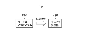
- FIG. 3 shows a configuration example of the transmission and reception system 10 according to the embodiment.
- the transmission / reception system 10 is configured of a service transmission system 100 and a service receiver 200.
- the service transmission system 100 corresponds to the DASH stream file server 31 and the DASH MPD server 32 of the stream distribution system 30 shown in FIG. 1 described above.
- the service receiver 200 corresponds to the service receivers 33 (33-1, 33-2,..., 33-N) of the stream distribution system 30 shown in FIG. 1 described above.
- the service transmission system 100 transmits DASH / MP4, that is, an MPD file as a metafile, and an MP4 (ISOBMFF) stream including media streams (media segments) such as video and audio, through a communication network channel (see FIG. 1). ,Send.
- DASH / MP4 that is, an MPD file as a metafile
- ISOBMFF MP4
- the MP4 stream includes a coded stream (coded image data) corresponding to a divided area (partition) obtained by dividing the wide viewing angle image.
- the wide-viewing-angle image is a projection image obtained by cutting a part or all of a spherical capture image and plane packing, but is not limited thereto.
- the encoded stream corresponding to each divided area of the wide view angle image can be obtained, for example, by individually coding each divided area of the wide view angle image, or each divided area of the wide view angle image is used as a tile. It is obtained by performing encoding using a tile function.
- the coded stream is hierarchically coded to facilitate temporal partial decoding at the receiver side.
- the coded stream corresponding to each divided area of the wide viewing angle image is transmitted together with the information on the number of pixels and the frame rate of each divided area.
- a descriptor having the number of pixels of the divided area and the frame rate is included in MP4, which is a container including the encoded stream of each divided area.
- the coded stream corresponding to the requested divided area is transmitted.
- the transmission band it is possible to prevent the transmission band from being unnecessarily wide, and efficient use of the transmission band becomes possible.
- the service receiver 200 receives the above-mentioned MP4 (ISOBMFF) stream transmitted from the service transmission system 100 through the communication network channel (see FIG. 1).
- the service receiver 200 acquires, from the MPD file, meta information on the encoded stream corresponding to each divided area of the wide-viewing angle image.
- the service receiver 200 requests the service transmission system (distribution server) 100 to transmit a predetermined number of encoded streams corresponding to the display area, receives and decodes the predetermined encoded stream, and displays image data of the display area. Get the image and display.
- a predetermined number of values are calculated based on the decoding capability and the information on the number of pixels and the frame rate respectively associated with the encoded stream corresponding to each divided area of the wide viewing angle image. It is required to be decodable as much as possible. As a result, it is possible to reduce the frequency of switching of the distribution encoded stream accompanying movement of the display area due to user operation or operation as much as possible, and the display performance in VR reproduction is improved.
- the decoding method when it is predicted that the display area goes out of the decoding range, the decoding method is switched from temporal full decoding to temporal partial decoding, and thereafter, If it is predicted that the display area converges within the decoding range, the decoding method is switched from temporal partial decoding to temporal full decoding.
- the number of decodable divided areas can be increased, the frequency of switching of the delivery encoded stream with respect to movement of the display area different from prediction can be reduced, and display in VR reproduction Performance is further improved.
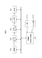
- FIG. 4 schematically shows an example of the overall configuration of the transmission / reception system 10.
- the service transmission system 100 includes a 360 ° image capture unit 102, a plane packing unit 103, a video encoder 104, a container encoder 105, and a storage 106.
- the 360 ° image capture unit 102 captures an object with a predetermined number of cameras, and obtains image data of a wide view angle image, in this embodiment, a spherical capture image (360 ° VR image).
- a spherical capture image 360 ° VR image
- the 360 ° image capture unit 102 performs imaging in a back-to-back method, and as a spherical capture image, each has a viewing angle of 180 ° or more imaged using a fisheye lens. Obtain front and back images of a wide viewing angle.
- the plane packing unit 103 cuts out part or all of the spherical captured image obtained by the 360 ° image capturing unit 102 and plane packing to obtain a projection picture.
- a projection picture In this case, as the format type of the projection image, for example, an equal rectangle, a cross-cubic or the like is selected.
- the plane packing unit 103 performs scaling on the projection image as necessary to obtain a projection image of a predetermined resolution.
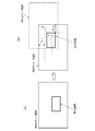
- FIG. 5A shows an example of a front image and a rear image of an ultra-wide viewing angle as a spherical capture image obtained by the 360 ° image capture unit 102.
- FIG. 5B illustrates an example of a projection image obtained by the plane packing unit 103. This example is an example in the case where the format type of the projection image is an exact rectangle. This example is an example of cutting out at the latitude shown by the broken line in each image shown in FIG. 5 (a).
- FIG. 5C shows another example of the projection image obtained by the plane packing unit 103. This example is an example in the case where the format type of the projection image is cross cubic.
- the video encoder 104 performs encoding such as MPEG4-AVC or HEVC on the image data of the projection image from the plane packing unit 103 to obtain encoded image data, and this encoding is performed. Generate a coded stream containing image data. In this case, the video encoder 104 divides the projection image into a plurality of partitions (division areas), and obtains a coded stream corresponding to each partition.
- FIG. 6A shows an example of division in the case where the format type of the projection image is an equi-rectangler.
- FIG. 6B shows an example of division in the case where the format type of the projection image is cross cubic. Note that the method of dividing the projection image is not limited to this example, and, for example, the sizes of all the partitions may not be the same.
- the video encoder 104 encodes, for example, each partition individually or collectively encodes the entire projection image in order to obtain an encoded stream corresponding to each partition of the projection image. Coding is performed using the tile function to be a tile. As a result, on the receiving side, it becomes possible to decode the coded stream corresponding to each partition independently.
- FIG. 7A shows an example of hierarchical coding.
- the vertical axis shows the hierarchy.
- the horizontal axis indicates the display order (POC: picture order of composition), the left side is the display time before, and the right side is the display time after.
- Each rectangular frame indicates a picture, and a number indicates a display order.
- Solid arrows indicate reference relationships of pictures in encoding.
- each picture is classified into three layers of sub layer 2 (Sub layer 2), sub layer 1 (Sub layer 1) and full layer (Full Layer), and coding is applied to image data of pictures of each layer.
- the picture of "0" corresponds to the I picture
- the picture of "1" corresponds to the b picture
- the picture of "2” corresponds to the B picture
- the picture of "3" corresponds to the b picture
- And "4" correspond to P pictures.
- sublayer 1 In this hierarchical coding, only sublayer 2 can be selectively decoded, and in that case, image data of a frame rate of 1 ⁇ 4 can be obtained. Further, in this hierarchical coding, sublayer 1 and sublayer 2 can be selectively decoded, and in this case, image data of a frame rate of 1/2 can be obtained. Furthermore, in this hierarchical coding, all of the sublayer 1, sublayer 2 and full layer can be decoded, in which case full frame rate image data can be obtained.
- FIG.7 (b) has shown another example of hierarchical encoding.
- the vertical axis shows the hierarchy.
- the horizontal axis indicates the display order (POC: picture order of composition), the left side is the display time before, and the right side is the display time after.
- Each rectangular frame indicates a picture, and a number indicates a display order.
- Solid arrows indicate reference relationships of pictures in encoding.
- This example is an example in which each picture is classified into two layers of sub layer 1 (Sub layer 1) and full layer (Full Layer), and coding is performed on image data of pictures of each layer.
- Sub layer 1 sub layer 1
- Full Layer Full Layer
- the picture of “0” corresponds to the I picture
- the pictures of “1” to “3” correspond to the b picture
- the picture of “4” corresponds to the P picture.
- sublayer 1 In this hierarchical coding, only sublayer 1 can be selectively decoded, and in that case, image data of a frame rate of 1 ⁇ 4 can be obtained. Also, in this hierarchical coding, all of the sublayer 1 and the full layer can be decoded, and in that case, full frame rate image data can be obtained.
- the container encoder 105 generates a container including the encoded stream generated by the video encoder 104, here, an MP4 stream as a delivery stream.
- a plurality of MP4 streams each including a coded stream corresponding to each partition are generated.
- the container encoder 105 When encoding is performed using a tile function in which each partition is a tile, the container encoder 105 includes sublayer information and the like in addition to a plurality of MP4 streams each including the encoded stream corresponding to each partition. Generate a base MP4 stream (base container) including parameter sets such as SPS.
- a tile is capable of dividing a picture in horizontal and vertical directions and encoding / decoding each independently. Since the tile can refresh intra prediction, loop filter and entropy coding in a picture, it is possible to independently encode / decode each region divided as a tile.
- FIG. 8A shows an example in which a picture is divided into four in total of vertical and horizontal divisions, and each partition is encoded as a tile.
- FIG. 8B a list of byte positions of the first data of each tile is described in the slice header for the tile-partitioned a, b, c, d partitions (tiles). Independent decoding is possible.
- the receiving side can reconstruct the original picture. For example, as shown in FIG. 8C, when the encoded stream of the partitions b and d enclosed by a rectangular frame of a dashed dotted line is decoded, the partitions (tiles) of the partitions b and d can be displayed.
- the sub-layer information is arranged in one SPS in a picture. Therefore, meta information such as a parameter set is stored in a tile-based MP4 stream (tile-based container). Then, in the MP4 stream (tile container) of each partition, a coded stream corresponding to each partition is stored as slice information.
- the container encoder 105 inserts information on the number of pixels of the partition and the frame rate in the layer of the container.
- a partition descriptor (partition_descriptor) is inserted in an initialization segment (IS) of the MP4 stream.
- IS initialization segment
- a plurality of partition descriptors may be inserted in units of pictures as the maximum frequency.
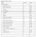
- FIG. 9 shows an example structure (Syntax) of the partition descriptor.
- FIG. 10 also shows the contents (Semantics) of the main information in the structural example.
- An 8-bit field of "partition_descriptor_tag” indicates a descriptor type, which indicates that it is a partition descriptor.
- the 8-bit field "partition_descriptor_length” indicates the length (size) of the descriptor, and indicates the number of subsequent bytes as the length of the descriptor.
- the 8-bit field "frame_rate” indicates the frame rate (full frame rate) of the partition (divided picture).
- a 1-bit field of "tile_partition_flag” indicates whether or not the picture is divided in a tile system. For example, “1” indicates that the picture is divided in the tile system, and “0” indicates that the picture is not divided in the tile system.
- a 1-bit field of "tile_base_flag” indicates whether it is a base container or not in the case of tile system. For example, “1” indicates that it is a base container, and "0” indicates that it is a container other than the base container.
- An 8-bit field of "partition_ID” indicates the ID of the partition.
- the 16-bit field “whole_picture_size_horizontal” indicates the number of horizontal pixels in the entire picture.
- the 16-bit field “whole_picture_size_vertical” indicates the number of vertical pixels in the entire picture.
- the 16-bit field "partition_horizontal_start_position” indicates the horizontal start pixel position of the partition.
- the 16-bit field “partition_horizontal_end_position” indicates the horizontal end pixel position of the partition.
- the 16-bit field “partition_vertical_start_position” indicates the vertical start pixel position of the partition.
- the 16-bit field “partition_vertical_end_position” indicates the vertical end pixel position of the partition.
- An 8-bit field of "number_of_sublayers” indicates the number of sublayers in hierarchical coding of partitions.
- the 8-bit field of "sublayer_id” and the 8-bit field of "sublayer_frame_rate” are repeated in the for loop by the number of sublayers.
- the field of “sublayer_id” indicates the sublayer ID of the partition, and the field of “sublayer_frame_rate” indicates the frame rate of the sublayer of the partition.
- the storage 106 temporarily accumulates the MP4 stream of each partition generated by the container encoder 105. In the case of division by tile method, the storage 106 also accumulates tile-based MP4 streams. Among the MP4 streams accumulated in this way, the MP4 stream of the partition for which the transmission request has been made is transmitted to the service receiver 200. In addition, when it is divided by the tile method, the MP4 stream of the base is also simultaneously transmitted.
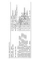
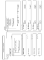
- FIG. 11 shows an example of description of an MPD file corresponding to tile-based MP4 stream (tile-based container).
- this MPD file there is an adaptation set (AdaptationSet) corresponding to one MP4 stream (track) as a tile-based container.
- AdaptationSet adaptation set
- AdaptationSet the video stream of which is provided in an MP4 file structure, indicating the presence of a HEVC encoded video stream (encoded image data).
- a representation (Representation) corresponding to the video stream exists.
- the rate and the type of codec are indicated, and it is further indicated that the level "0" is given as tag information.
- the location destination of this MP4 stream is indicated as "videostream VR.
- Mp 4" by the description of " ⁇ Base URL> video stream VR.
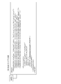
- FIG. 12 shows an example of description of an MPD file corresponding to the MP4 stream of each partition.
- an adaptation set AdaptationSet
- tracks an adaptation set corresponding to each of a plurality of MP4 streams (tracks) exists.
- AdaptationSets two adaptation sets
- the first adaptation set will be described, and the other adaptation sets are similar, so the description will be omitted.
- the video stream is provided in an MP4 file structure, indicating the presence of a HEVC encoded video stream (encoded image data).
- a representation (Representation) corresponding to the video stream exists.
- the rate and the type of codec are indicated, and it is further indicated that the level "0" is given as tag information.
- the location destination of this MP4 stream is indicated as "videostream VR0.mp4" by the description of " ⁇ BaseURL> videostreamVR0.mp4 ⁇ / BaseURL>”.
- FIG. 13 schematically shows an MP4 stream (track) when encoding is performed using a tile function in which each partition is a tile.
- each partition is a tile.
- each random access period starts from an initialization segment (IS: initialization segment), and “styp”, “sidx (Segment index box)”, “ssix (Sub-segment index) It is configured such that boxes “box”, “moof (Movie fragment box)”, and “mdat (Media data box)” are continued.
- the initialization segment (IS) has a box structure based on ISO Base Media File Format (ISOBMFF).
- ISOBMFF ISO Base Media File Format
- a partition descriptor (see FIG. 9) is inserted in this initialization segment (IS).
- the MP4 stream (tile container) of the first to fourth partitions “partition ID” is 1 to 4.
- Segment type information is entered in the "styp” box.
- range information of each track (track) is entered, the position of "moof” / “mdat” is shown, and the position of each sample (picture) in “mdat” is also shown.
- the “ssix” box contains track classification information, and I / P / B type classification.
- the "moof” box contains control information.
- VPS ",” SPS ",” PPS ",” PSEI ", and” SSEI "NAL units are arranged.
- NAL unit of" SLICE "having the encoded image data of each partition is arranged.
- FIG. 14 schematically shows an MP4 stream (track) in the case where each partition is individually encoded.
- each partition there are four partitions of MP4 streams.
- each random access period starts from an initialization segment (IS: initialization segment), and “styp”, “sidx (Segment index box)”, “ssix (Sub-segment index) It is configured such that boxes “box”, “moof (Movie fragment box)”, and “mdat (Media data box)” are continued.
- the initialization segment (IS) has a box structure based on ISO Base Media File Format (ISOBMFF).
- ISOBMFF ISO Base Media File Format
- a partition descriptor (see FIG. 9) is inserted in this initialization segment (IS).
- the “partition ID” is 1 to 4.
- Segment type information is entered in the "styp” box.
- range information of each track (track) is entered, the position of "moof” / “mdat” is shown, and the position of each sample (picture) in “mdat” is also shown.
- the “ssix” box contains track classification information, and I / P / B type classification.
- the "moof” box contains control information.
- VPS ",” SPS “,” PPS “,” PSEI “,” SLEI ", and” SSEI "NAL units are arranged.
- the service receiver 200 includes a container decoder 203, a video decoder 204, a renderer 205, and a transmission request unit 206.
- the transmission request unit 206 requests the service transmission system 100 to transmit an MP4 stream of a predetermined number of partitions corresponding to the display area among the partitions of the projection image.
- the predetermined number of values are set to the maximum or near decodable value based on the decoding capability and the information on the number of pixels in the coded stream of each partition of the projection image and the frame rate. Ru.
- the information on the number of pixels and the frame rate in the encoded stream of each partition can be acquired from the MPD file (see FIG. 12) previously received from the service transmission system 100.
- FIG. 15 shows an example of dividing an 8K / 60 Hz grade projection image with a partition size of 1920 ⁇ 1080 (Full HD).
- the level value of complexity required to decode a partition is “Level 4.1”.
- the service receiver 200 can decode up to four partitions.
- the four partitions indicated by the arrow P indicate examples of partitions corresponding to the display area selected in this case.
- the service receiver 200 can decode up to eight partitions.
- the eight partitions indicated by the arrow Q show an example of partitions corresponding to the display area selected in this case.
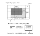
- FIG. 16 shows an example of dividing an 8K / 60 Hz grade projection image with a partition size of 1280 ⁇ 960 (4 VGA).
- the level value of complexity required to decode a partition is “Level 4.1”.
- the service receiver 200 can decode up to seven partitions. Six partitions indicated by an arrow P indicate examples of partitions corresponding to the display area selected in this case.
- the service receiver 200 has a “Level 5.2” decoder for decoding at 4K / 120 Hz
- the Luma maximum number of pixels in a plane is 8912896
- the service receiver 200 can decode up to 14 partitions. Twelve partitions indicated by an arrow Q show an example of a partition corresponding to the display area selected in this case.
- FIG. 17 shows an example of dividing a projection image exceeding 8K / 60 Hz with a partition size of 1280 ⁇ 960 (4 VGA).
- the level value of complexity required to decode a partition is “Level 4.1”.
- the service receiver 200 can decode up to seven partitions. Seven partitions indicated by an arrow P indicate examples of partitions corresponding to the display area selected in this case.
- the service receiver 200 has a “Level 5.2” decoder for decoding at 4K / 120 Hz
- the Luma maximum number of pixels in a plane is 8912896
- the service receiver 200 can decode up to 14 partitions. Fourteen partitions indicated by an arrow Q indicate an example of partitions corresponding to the display area selected in this case.
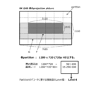
- FIG. 18 shows an example of dividing an 8K / 60 Hz grade projection image with a partition size of 1280 ⁇ 720 (720 p HD).
- the level value of the complexity required to decode the partition is "Level 4".
- the service receiver 200 can decode up to nine partitions. Eight partitions indicated by an arrow P indicate examples of partitions corresponding to the display area selected in this case.
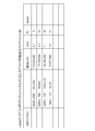
- FIG. 19 collectively shows the decodable maximum number of partitions according to the partition size in the “Level 5.1” decoder.
- the partition size is 1920 ⁇ 1080 (Full HD)
- the maximum pixel count that can be processed per second by the decoder is 534773760
- the pixel rate of the partition is 124416000 (equivalent to Level 4.1)
- the maximum decodable The number of partitions is four.
- the partition size is 1280 ⁇ 960 (4 VGA)
- the maximum pixel count that can be processed per second of the decoder is 534773760
- the pixel rate of the partition is 73728000 (equivalent to Level 4.1) and can be decoded
- the maximum number of partitions is seven.
- the maximum pixel count that can be processed per second by the decoder is 534773760, while the pixel rate of the partition is 55296000 (equivalent to Level 4), and the maximum decodable The number of partitions is nine.
- the partition size is 960 ⁇ 540 (QHD)
- the maximum pixel count that can be processed per second by the decoder is 534773760, while the pixel rate of the partition is 33177600 (equivalent to Level 3.1), which allows decoding
- the maximum number of partitions is 16.
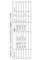
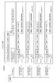
- FIG. 20 collectively shows the decodable maximum number of partitions according to the partition size in the “Level 5.2” decoder.
- the partition size is 1920 ⁇ 1080 (Full HD)
- the maximum pixel count that can be processed per second of the decoder is 1069547520
- the pixel rate of the partition is 124416000 (equivalent to Level 4.1)
- the maximum decodable The number of partitions is eight.
- the partition size is 1280 ⁇ 960 (4 VGA)
- the maximum pixel count that can be processed per second of the decoder is 1069547520, while the pixel rate of the partition is 73728000 (equivalent to Level 4.1), so that decoding is possible
- the maximum number of partitions is 14.
- the maximum pixel count that can be processed per second by the decoder is 1069547520, while the pixel rate of the partition is 55296000 (equivalent to Level 4), and the maximum decodable The number of partitions is 19. Also, when the partition size is 960 ⁇ 540 (QHD), the maximum pixel count that can be processed per second of the decoder is 1069547520, while the pixel rate of the partition is 33177600 (equivalent to Level 3.1), which allows decoding The maximum number of partitions is 32.
- the transmission request unit 206 may be provided with a table as shown in FIG. 19 or 20, and may refer to this table to obtain the maximum value (the maximum number of decodable partitions).
- the transmission request unit 206 determines the number of partitions that can be decoded or the maximum number of decodable values as a partition corresponding to the display area that requests the service transmission system 100 to transmit based on the pixel rate of each partition. Choose
- FIG. 21 shows the case where the number of pixels in each partition is not uniform.
- ID1, ID2, ID3, ID4, ID5 and ID6 are respectively (H0, V0), (H0, V1), (H1, V1), (H0, V2), (H1, V2), (H0, V3) Indicates the partition ID of the partition in the position of.
- the pixel rates of the partitions whose partition IDs are ID1, ID2, ID3, ID4, ID5, and ID6 are R1, R2, R3, R4, R5, R5, and R6, respectively. If the decoder of the service receiver 200 is “Level X” and the pixel rate corresponding to it is D1, for example, if R1 + R2 + R3 ⁇ D1, then it is possible to decode the partitions with partition ID ID1, ID2, and ID3. It can be said.
- the container decoder 203 extracts the coded stream of each partition from the MP4 stream of the predetermined number of partitions corresponding to the display area sent from the service transmission system 100 and sends it to the video decoder 204.
- the container decoder 203 also sends to the video decoder 204 a coded stream including parameter set information and the like included in the tile-based MP4 stream.
- the video decoder 204 decodes the coded stream of a predetermined number of partitions corresponding to the display area to obtain image data of the predetermined number of partitions corresponding to the display area.
- the renderer 205 performs rendering processing on the image data of the predetermined number of partitions obtained in this manner, and obtains a rendered image (image data) corresponding to the display area.
- the movement of the display area is controlled according to sensor information, pointing information, voice UI information, and the like.
- sensor information pointing information
- voice UI information voice UI information
- the display area is controlled based on information on the direction and amount of movement obtained by a gyro sensor or the like mounted on the HMD with movement of the user's neck. Is controlled.
- the display panel is used as the display device, the movement of the display area is controlled based on the pointing information by the user operation or the voice UI information of the user.
- FIG. 22 shows the case where an HMD is used as a display device.
- the display area observed by the HMD becomes a diagram as shown in FIG.
- the movement proceeds as P1 ' ⁇ P2' ⁇ P3 '.
- FIG. 23 shows a case where a display panel such as a TV is used as a display device.
- the voice instruction is changed as P1.fwdarw.P2.fwdarw.P3
- the display area displayed on the display panel is as shown in FIG. 23 (a). It moves as P1 ′ ⁇ P2 ′ ⁇ P3 ′.
- the transmission request unit 206 determines switching of a set of MP4 streams of a predetermined number of partitions corresponding to the display area, in order to set the display area as a decoding range. Request the service transmission system 100 to transmit a new set (delivery stream set).
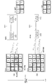
- FIG. 24 illustrates an example of switching of a delivery stream set accompanying movement of a display area.
- This example is an example in which MP4 streams of four partitions corresponding to the display area are transmitted (distributed).
- the partitions corresponding to the display area are (H0, V1), (H1, V1), (H0, V2), and (H1, V2).
- Partitions, and MP4 streams of these partitions are transmitted, for example, in the order of (1) ⁇ (2) ⁇ (5) ⁇ (6).
- the coded stream is extracted from the MP4 stream of these partitions and decoded by the video decoder 204. That is, the decoding range in this case is a partition at the positions of (H0, V1), (H1, V1), (H0, V2), and (H1, V2).
- the partitions corresponding to the display area are (H1, V1), (H2, V1), (H1, V2), (H2, V2) There will be 4 partitions in the position of. Therefore, switching of the delivery stream set is performed, and the MP4 streams of these partitions are transmitted in the order of (2) ⁇ (3) ⁇ (6) ⁇ (7), for example.
- the coded stream is extracted from the MP4 stream of these partitions and decoded by the video decoder 204. That is, the decoding range in this case is a partition at the positions of (H1, V1), (H2, V1), (H1, V2), and (H2, V2).
- the partitions corresponding to the display area are (H2, V1), (H3, V1), (H2, V2), (H3, V2) There will be 4 partitions in the position of. Therefore, switching of the delivery stream set is performed, and the MP4 streams of these partitions are transmitted, for example, in the order of (3) ⁇ (4) ⁇ (7) ⁇ (8).
- the coded stream is extracted from the MP4 stream of these partitions and decoded by the video decoder 204. That is, the decoding range in this case is a partition at the positions of (H2, V1), (H3, V1), (H2, V2), and (H3, V2).
- FIG. 25 illustrates another example of switching of a delivery stream set as the display area moves.
- This example is an example in which MP4 streams of six partitions corresponding to the display area are transmitted (distributed).
- the partitions corresponding to the display area are (H0, V1), (H1, V1), (H2, V1), (H0, V2), For example, (1) ⁇ (2) ⁇ (3) ⁇ (5) ⁇ (5) ⁇ (6) ⁇ (7) MP1 streams of H1 and V2) and (H2 and V2) are obtained. Sent in the order of).
- the coded stream is extracted from the MP4 stream of these partitions and decoded by the video decoder 204. That is, the decoding range in this case is a partition at the positions of (H0, V1), (H1, V1), (H2, V1), (H0, V2), (H1, V2), (H2, V2) .
- the partitions corresponding to the display area are (H0, V1), (H1, V1), (H2, V1), (H0, V1)
- the six partitions remain at V2), (H1, V2), (H2, V2). Therefore, there is no switching of the delivery stream set, and the MP4 streams of these partitions are transmitted, for example, in the order of (1) ⁇ (2) ⁇ (3) ⁇ (5) ⁇ (6) ⁇ (7).
- the coded stream is extracted from the MP4 stream of these partitions and decoded by the video decoder 204. That is, the decoding range in this case is a partition at the positions of (H1, V1), (H2, V1), (H1, V2), and (H2, V2).
- the partitions corresponding to the display area are (H1, V1), (H2, V1), (H3, V1), (H1, V2) , (H2, V2), (H3, V2) positions of six partitions. Therefore, switching of the delivery stream set is performed, and the MP4 streams of these partitions are transmitted, for example, in the order of (2) ⁇ (3) ⁇ (4) ⁇ (6) ⁇ (7) ⁇ (8).
- the coded stream is extracted from the MP4 stream of these partitions and decoded by the video decoder 204. That is, the decoding range in this case is a partition at the positions of (H1, V1), (H2, V1), (H3, V1), (H1, V2), (H2, V2), (H3, V2) .
- the switching frequency of the delivery stream set accompanying the movement of the display area is suppressed low. It is possible to improve the display performance in VR reproduction.
- the transmission request unit 206 determines to switch the distribution stream set and requests the service transmission system 100 to transmit a new distribution stream set. .
- this prediction is performed by a control unit that controls the operation of each unit of the service receiver 200.
- FIG. 26A shows a state in which the display area falls within the current decoding range.
- FIG. 26B shows a state in which the display area has moved in the direction indicated by the broken line arrow m from that state.
- a solid arrow n indicates the movement speed and movement direction of the display area detected in the last few frames.
- the transmission request unit 206 determines a new predetermined number of partitions based on the movement prediction of the display area so as to obtain a new decoding range in which the display area is included, and a new MP4 stream is generated.
- the service transmission system 100 is requested to transmit various distribution stream sets.
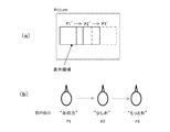
- FIG. 27 shows how the decoding range is switched when the display area moves.
- solid arrows indicate the predicted movement direction of the display area
- broken arrows indicate the actual movement direction of the display area.
- FIG. 27B shows the case where the delivery stream set is switched based on the movement prediction direction of the display area from the state of FIG. 27A, and the actual movement direction of the display area is the movement prediction direction It shows the state in which it was fitted. In this case, there is no problem because the display area falls within the decoding range.
- FIG. 27C shows the case where the delivery stream set is switched based on the movement prediction direction of the display area from the state of FIG. 27B, and the actual movement direction of the display area is movement prediction. It shows the state when it matches the direction. In this case, there is no problem because the display area falls within the decoding range.
- FIG. 27D shows the case where the delivery stream set is switched based on the movement prediction direction of the display area from the state of FIG. 27B, and the actual movement direction of the display area is the movement prediction direction. It shows the situation when it did not fit. In this case, since the display area does not fall within the decoding range, it is necessary to switch the stream set again and change to the decoding range indicated by hatching so that the display area falls within the decoding range. It becomes. In such a case, there is a possibility that the display may be temporarily frozen due to a time lag before switching.
- the number of partitions is increased so that the display area after movement is positioned at the center of the decoding range.
- the normal decode mode is changed to the wide decode mode.
- temporal partial decoding ie, a sub-layer, is performed on a part or all of the encoded stream of a predetermined number of partitions so that the predetermined number of partitions can be decoded in the wide decoding mode. Decoding is performed.
- FIG. 28 shows how the decoding range is switched when the display area moves.
- solid arrows indicate the predicted movement direction of the display area
- broken arrows indicate the actual movement direction of the display area.
- FIG. 28 (b) is the case where the delivery stream set is switched based on the movement prediction direction of the display area from the state of FIG. 28 (a), and the actual movement direction of the display area is the movement prediction direction. It shows the state in which it was fitted. In this case, the number of partitions is increased to widen the decoding range on the premise that temporal partial decoding is performed. In this case, the display area falls within the decoding range.
- FIG.28 (c) has shown the state which the display area moved from the state of FIG.28 (b). In this case, a state is shown in which the actual movement direction of the display area matches the movement prediction direction. In this case, since the decoding range is expanded, the movement of the display area is the movement within the decoding range, and therefore, the switching of the delivery stream set is not performed.
- FIG. 28 (d) shows a state in which the display area has moved from the state shown in FIG. 28 (b). In this case, a state is shown in which the actual movement direction of the display area does not match the movement prediction direction. In this case, since the decoding range is expanded, the movement of the display area is the movement within the decoding range, and therefore, the switching of the delivery stream set is not performed.
- FIG. 29 shows the frame rate of each partition in the case where the video coding is tile compatible. In this case, the frame rate and layering of hierarchical coding are the same for all partitions.
- FIG. 29A shows that decoding processing at a full frame rate is performed in the normal decoding mode.
- FIG. 29 (b) shows that temporal partial decoding, for example, decoding at half rate is performed in the wide decoding mode.
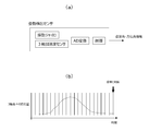
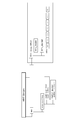
- FIG. 30 shows the frame rate of partitions in the case where video coding is encoded into independent streams for each partition.
- the frame rate and the layering of hierarchical coding may not be the same for all partitions, since different coding is possible for each partition.
- the central six partitions are set to 120 Hz at the high frame rate, while the peripheral ten partitions are set to 60 Hz at the low frame rate.
- FIG. 30A shows that the decoding process is performed at the full frame rate in the normal decoding mode.
- FIG. 30 (b) shows that temporal partial decoding, for example, decoding at half rate is performed in the wide decoding mode.
- FIG. 30C in the wide decode mode, the decoding process at the full frame rate is performed in the central six partitions, and the decoding process is performed at the quarter rate in the peripheral ten partitions. It shows.
- the transmission request unit 206 requests the service transmission system 100 to stop transmission other than the predetermined number of partitions in the normal decode mode.
- the convergence prediction is performed by observing a change in movement of the display area. Although not shown in FIG. 4, this prediction is performed by a control unit that controls the operation of each unit of the service receiver 200. For example, in the case where an HMD is used as a display device, it is possible to determine the convergence based on attitude angle / azimuth information obtained from the attitude detection sensor mounted on the HMD.
- FIG. 31A schematically shows the configuration of the posture detection sensor.
- the attitude detection sensor includes a vibrating gyroscope and a three-axis acceleration sensor. Variation of the position of each of the pitch, roll, and yaw three axes by the vibration gyro, and the acceleration applied to each of the X, Y, and Z axes by the three-axis acceleration sensor, finally the attitude angle (roll angle, pitch angle), and azimuth Corner information is output.
- FIG. 32 shows an example of mode change control.
- the normal decode mode is set.
- the normal decode mode is switched to the wide decode mode accordingly.
- T3 movement of the display area is detected, but since the position of the display area is within the wide decoding range at T2, the decoding range is not updated.
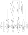
- the flowchart in FIG. 33 illustrates an example of control processing of decoding range change and mode change in the control unit of the service receiver 200.
- the control unit executes this control process, for example, in a video frame cycle.
- control unit starts processing in step ST1.
- step ST2 the control unit detects the movement of the display area.
- the movement of the display area is detected based on, for example, sensor information, pointing information or voice UI information.
- step ST3 the control unit determines whether the display area is predicted to be out of the current decoding range. This determination is made based on whether the display area satisfies the position condition and the movement condition as described above. When the display area is not predicted to be out of the current decoding range, the control unit determines whether or not the wide decoding mode is in step ST4. When in the wide decode mode, the control unit proceeds to the process of step ST5.
- step ST5 the control unit determines whether the display area is predicted to converge within the decoding range corresponding to the normal decoding mode. This determination is made by observing the change in movement of the display area including the past several frames, as described above. When it is predicted that convergence will occur, the control unit changes from the wide decode mode to the normal decode mode in step ST6.
- step ST6 the control unit ends the process in step ST7.
- the control unit proceeds to step ST7 and ends the process.
- the control unit determines in step ST8 whether or not it is in the normal decoding mode.
- the control unit changes to the wide decoding mode in step ST9, and changes the decoding range in step ST10.
- the server service transmission system 100
- the server is requested to set (delivery stream set) of MP4 streams of a predetermined number of partitions corresponding to the display area and according to the decoding mode. You will receive a stream set.
- step ST10 the control unit proceeds to step ST7 and ends the process. Further, when in the wide decoding mode in step ST8, the control unit proceeds to step ST9 to change the decoding range, and thereafter ends the processing in step ST7.
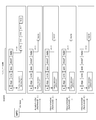
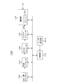
- FIG. 34 shows a configuration example of the service transmission system 100.
- the service transmission system 100 includes a communication unit 107 including a control unit 101, a user operation unit 101a, a 360 ° image capture unit 102, a plane packing unit 103, a video encoder 104, a container encoder 105, and a storage 106.
- a communication unit 107 including a control unit 101, a user operation unit 101a, a 360 ° image capture unit 102, a plane packing unit 103, a video encoder 104, a container encoder 105, and a storage 106.
- the control unit 101 includes a CPU (Central Processing Unit), and controls the operation of each unit of the service transmission system 100 based on a control program.
- the user operation unit 101a is a keyboard, a mouse, a touch panel, a remote control, or the like for the user to perform various operations.
- the 360 ° image capture unit 102 captures an object with a predetermined number of cameras, and obtains image data of a spherical capture image (360 ° VR image). For example, the 360 ° image capture unit 102 performs imaging in a back-to-back method, and as a spherical capture image, each has a viewing angle of 180 ° or more imaged using a fisheye lens. Front and back images of a wide viewing angle are obtained (see FIG. 5 (a)).
- the plane packing unit 103 cuts out part or all of the spherical captured image obtained by the 360 ° image capturing unit 102 and plane packing to obtain a rectangular projection picture (Fig. 5 (b), (c). )reference).
- a rectangular projection picture Fig. 5 (b), (c). )reference.
- the format type of the projection image for example, an equal rectangle, a cross-cubic or the like is selected.
- the video encoder 104 performs encoding such as MPEG4-AVC or HEVC on the image data of the projection image from the plane packing unit 103 to obtain encoded image data, and includes the encoded image data. Generate a stream In this case, the video encoder 104 divides the projection image into a plurality of partitions (division areas), and obtains a coded stream corresponding to each partition.
- the video encoder 104 encodes each partition individually or collectively encodes the entire projection image, for example, in order to obtain a coded stream corresponding to each partition of the projection image. It encodes using the tile function which makes each partition a tile. As a result, on the receiving side, it becomes possible to decode the coded stream corresponding to each partition independently. Also, the video encoder 104 performs hierarchical coding on each partition (see FIGS. 7A and 7B). This hierarchical coding allows the receiver to easily perform temporal partial decoding.
- the container encoder 105 generates a container including the encoded stream generated by the video encoder 104, here, an MP4 stream as a delivery stream.
- an MP4 stream as a delivery stream.
- a plurality of MP4 streams respectively including coded streams corresponding to each partition are generated (see FIGS. 13 and 14).
- the container encoder 105 when encoding is performed using a tile function in which each partition is a tile, the container encoder 105 performs sub-layer information etc. in addition to a plurality of MP4 streams each including a coded stream corresponding to each partition.
- a base MP4 (base container) including parameter sets such as SPS is generated (see FIG. 13).
- the container encoder 105 inserts a partition descriptor (see FIG. 9) into the layer of the container, specifically, the initialization segment (IS) of MP4.
- the partition descriptor contains information such as the number of pixels of the partition and the frame rate.
- the storage 106 included in the communication unit 107 stores the MP4 stream of each partition generated by the container encoder 105. In the case of division by tile method, the storage 106 also accumulates tile-based MP4 streams. The storage 106 also stores, for example, an MPD file (see FIGS. 11 and 12) generated by the container decoder 105.
- the communication unit 107 receives the distribution request request from the service receiver 200, and transmits the MPD file to the service receiver 200 in response thereto.
- the service receiver 200 recognizes the configuration of the delivery stream from this MPD file.
- the communication unit 107 receives a distribution request (transmission request) of the MP4 stream corresponding to the predetermined number of partitions corresponding to the display area from the service receiver 200, and transmits the MP4 stream to the service receiver 200.
- the partition ID specifies a required partition.
- FIG. 35 shows a configuration example of the service receiver 200.
- the service receiver 200 includes a control unit 201, a UI unit 201a, a sensor unit 201b, a communication unit 202, a container decoder 202, a video decoder 204, a renderer 205, and a display unit 207.
- the control unit 201 includes a CPU (Central Processing Unit), and controls the operation of each unit of the service receiver 200 based on a control program.
- the UI unit 201a is for performing a user interface, and for example, a pointing device for the user to operate the movement of the display area or a microphone for the user to input voice for instructing the movement of the display area by voice. Etc. are included in this.
- the sensor unit 201 b includes various sensors for acquiring information on user status and environment, and includes, for example, an attitude detection sensor and the like mounted on a head mounted display (HMD).
- HMD head mounted display
- the communication unit 202 transmits a distribution request request to the service transmission system 100 under the control of the control unit 201, and correspondingly receives an MPD file (see FIGS. 11 and 12) from the service transmission system 100.
- the communication unit 202 sends this MPD file to the control unit 201.
- the control unit 201 recognizes the configuration of the delivery stream.
- the communication unit 202 transmits, to the service transmission system 100, a distribution request (transmission request) of the MP4 stream corresponding to the predetermined number of partitions corresponding to the display area.
- the service transmission system 100 receives an MP4 stream corresponding to a predetermined number of partitions.
- control unit 101 determines the direction of movement of the display area based on information on the direction and amount of movement obtained by a gyro sensor or the like mounted on the HMD, or based on pointing information by user operation or voice UI information of the user. And obtains speed information, and selects a predetermined number of partitions corresponding to the display area.
- control unit 101 can decode a predetermined number of values at or near the maximum that can be decoded based on the decoding capability and the information on the number of pixels in the encoded stream of each partition recognized from the MPD file and the frame rate.
- Set to The transmission request unit 206 illustrated in FIG. 4 is configured by the control unit 101.
- control unit 101 detects the movement of the display area and determines whether the display area is predicted to be out of the current decoding range, and when the wide decoding mode is in effect, the display area is in the normal decoding mode. It is determined whether or not convergence occurs within the corresponding decoding range, and control processing of changing the decoding range and changing the mode is performed (see FIG. 33).
- the container decoder 203 takes out the encoded stream of each partition from the MP4 stream of the predetermined number of partitions corresponding to the display area received by the communication unit 202 and sends it to the video decoder 204.
- division is performed in the tile method, not only the MP4 stream of the predetermined number of partitions corresponding to the display area, but also the tile-based MP4 stream is received by the communication unit 202, so that tile-based division is performed.
- the encoded stream including parameter set information and the like included in the MP4 stream is also sent to the video decoder 204.
- the container decoder 203 takes out the partition descriptor (see FIG. 9) inserted in the initialization segment (IS) of each MP4 stream, and sends it to the control unit 201.
- the control unit 201 acquires, from this descriptor, information on the number of pixels and frame rate in each partition, and hierarchical coding information.
- the video decoder 204 decodes the encoded stream of a predetermined number of partitions corresponding to the display area supplied from the container decoder 203 to obtain image data.
- the video decoder 204 when in the normal decoding mode, performs processing of temporal full decoding on the coded stream of a predetermined number of partitions, but in the wide decoding mode.
- the partial decoding process is performed temporally on a part or all of the encoded stream of the predetermined number of partitions, decoding of the predetermined number of partitions in the wide decoding mode is enabled (see FIGS. 29 and 30). ).
- the renderer 205 performs rendering processing on image data of a predetermined number of partitions obtained by the video decoder 204, and obtains a rendered image (image data) corresponding to the display area.
- the display unit 207 displays the rendered image (image data) obtained by the renderer 205.
- the display unit 207 is configured of, for example, an HMD (Head Mounted Display), a display panel, or the like.
- the service transmission system 100 is configured to calculate the coded stream corresponding to each partition (division area) of the wide view angle image (projection image) Send along with frame rate information. Therefore, on the receiving side, the number of partitions to be decoded corresponding to the display area is easily decodable on the basis of the decoding capability and the information on the number of pixels and frame rate of each partition of the wide viewing angle image. This can be set, the frequency of switching of the encoded stream accompanying the movement of the display area can be minimized, and the display performance in VR reproduction can be improved.
- the service receiver 200 calculates the number of partitions to be decoded corresponding to the display area based on the decoding capability and the information of the number of pixels of each partition and the frame rate. Therefore, the number of partitions to be decoded can be set up as easily as possible corresponding to the display area, the frequency of switching of the encoded stream accompanying the movement of the display area can be minimized, and the display performance in VR reproduction is improved. Is possible.
- the service receiver 200 predicts that the display area goes out of the decoding range, switches the decoding method to temporal partial decoding, and the display area converges within the decoding range.
- switch the decoding method to temporal full decoding In this case, the number of decodable divided areas can be increased by switching the decoding method to temporal partial decoding, and the frequency of switching of the coded stream with respect to movement of the display area different from prediction can be reduced. Further improvement of the display performance in
- the container encoder 105 of the service transmission system 100 shown in FIG. 4 generates a transport stream including an encoded stream of each partition of the projection image.
- the container encoder 105 inserts a partition descriptor (Partition_descriptor) (see FIG. 9) into the video elementary stream loop corresponding to each encoded stream of the program map table (PMT: Program Map Table). .
- Partition_descriptor partition descriptor
- FIG. 36 shows a configuration example of a transport stream in the case where video coding is tile-compatible.
- PES packets "video PES0" of the tile-based encoded stream identified by PID0.
- NAL units of “AUD”, “VPS”, “SPS”, “PPS”, “PSEI”, and “SSEI” are arranged.
- PES packets “video PES1” to “video PES4” of the coded streams of the first to fourth partitions (tiles) identified by PID1 to PID4 exist.
- NAL units of “AUD” and “SLICE” are arranged.
- video elementary stream loops corresponding to PES packets “video PES 0” to “video PES 4” exist in the PMT.
- information such as a stream type and a packet identifier (PID) is disposed corresponding to the encoded stream, and a descriptor that describes information related to the encoded stream is also disposed.
- This stream type is "0x24" indicating a video stream.
- a partition descriptor is inserted as one of the descriptors.
- the container encoder 104 of the service transmission system 100 shown in FIG. 4 generates an MMT stream (MMT stream) including a video stream.
- the container encoder 104 inserts a partition descriptor (see FIG. 9) into a video asset loop corresponding to the extended video stream of the MMT package table (MPT: MMT Package Table).
- FIG. 37 shows an exemplary configuration of an MMT stream in the case where video coding is tile-compatible.
- MPU packets "video MPU 0" of the tile-based encoded stream identified by ID0.
- NAL units of “AUD”, “VPS”, “SPS”, “PPS”, “PSEI”, and “SSEI” are arranged.
- AUD and "SLICE” NAL units are arranged.
- video asset loops (video asset loops) corresponding to MPU packets “video MPU 0” to “video MPU 4” exist in the MPT.
- information such as an asset type and an asset identifier (ID) is arranged corresponding to a coded stream, and a descriptor describing information related to the coded stream is also arranged.
- This asset type is "0x24" indicating a video stream.
- a partition descriptor is inserted as one of the descriptors.
- FIG. 38 shows an example of description of an MPD file in the case where tile stream is configured as a single stream.
- an adaptation set (AdaptationSet) corresponding to the MP4 stream (track) corresponding to the tile stream is present.
- the video stream is provided in an MP4 file structure, indicating the presence of a HEVC encoded video stream (encoded image data).
- the description of the sublayer ID and frame rate of this partition is repeated by the number of sublayers.
- the above description from the partition ID to the sub-layer frame rate is repeated by the number of partitions in tile coding.
- a representation (Representation) corresponding to the video stream exists.
- the rate and the type of codec are indicated, and it is further indicated that the level "0" is given as tag information.
- the location destination of this MP4 stream is indicated as "videostreamVR0.mp4" by the description of " ⁇ BaseURL> videostreamVR.mp4 ⁇ / BaseURL>”.
- FIG. 39 schematically illustrates an MP4 stream (track) in the case where a tile stream is configured as a single stream.
- a tile stream is configured as a single stream.
- each random access period starts from an initialization segment (IS), and then “styp”, “sidx (Segment index box)”, “ssix (Sub-segment index box) It has a configuration in which boxes of “)”, “moof (Movie fragment box)” and “mdat (Media data box)” are continued.
- the initialization segment (IS) has a box structure based on ISO Base Media File Format (ISOBMFF).
- ISOBMFF ISO Base Media File Format
- a partition descriptor (see FIG. 9) is inserted in this initialization segment (IS).
- the partition descriptor in this case includes information on all partitions (tiles) in tile coding.
- FIG. 40 shows a configuration example of a transport stream in the case where tile streams are configured as a single stream.
- PES packets "video PES1" of the tile stream identified by PID1.
- NAL units of “AUD”, “VPS”, “SPS”, “PPS”, “PSEI”, “SLICE”, and “SSEI” are arranged.
- a video elementary stream loop (video ES1 loop) corresponding to the PES packet "video PES1" is present in the PMT.
- information such as a stream type and a packet identifier (PID) is arranged corresponding to the tile stream, and a descriptor that describes information related to the tile stream is also arranged.
- This stream type is "0x24" indicating a video stream.
- a partition descriptor (see FIG. 9) is inserted as one of the descriptors. The partition descriptor in this case includes information on all partitions (tiles) in tile coding.
- FIG. 41 shows a configuration example of an MMT stream in the case where tile streams are configured as a single stream.
- MPU packet “video MPU1” of the tile stream identified by ID1.
- NAL units of “AUD”, “VPS”, “SPS”, “PPS”, “PSEI”, “SLICE”, and “SSEI” are arranged.
- a video asset loop (video asset 1 loop) corresponding to the MPU packet “video MPU 1” exists in the MPT.
- information such as an asset type and an asset identifier (ID) is placed corresponding to the tile stream, and a descriptor that describes information related to the tile stream is also placed.
- This asset type is "0x24" indicating a video stream.
- a partition descriptor (see FIG. 9) is inserted as one of the descriptors. The partition descriptor in this case includes information on all partitions (tiles) in tile coding.
- the partition descriptor is also contained in the track that contains the "SLICE” of the encoded video (see FIGS. 13, 14, and 39).
- the partition descriptor is another track “track 1B, A configuration is also conceivable in which containers are used as "mdat" of 2B, 3B, 4B ".
- the track containing each partition descriptor specifies the reference target of the track containing the encoded video by "tref" in its own initialization segment (IS).
- transmitting and receiving system 10 which consists of service transmitting system 100 and service receiver 200
- the composition of the transmitting and receiving system which can apply this art is not limited to this.
- the television receiver 200 is a set top box and display connected by a digital interface such as, for example, a high-definition multimedia interface (HDMI).
- HDMI high-definition multimedia interface
- the present technology can also be configured as follows.
- a transmitting device that transmits a coded stream corresponding to each divided region of a wide viewing angle image, and transmits information on the number of pixels in each divided region and the frame rate.
- the wide-viewing-angle image is a projection image obtained by plane-packing a part or all of a spherical captured image.
- a coded stream corresponding to each divided area of the wide-viewing-angle image is obtained by individually coding each divided area of the wide-viewing-angle image according to (1) or (2). Transmitter.
- the encoded stream corresponding to each divided area of the wide-viewing-angle image is obtained by performing encoding using a tile function in which each divided area of the wide-viewing-angle image is used as a tile. Or the transmitter as described in (2).
- the transmission unit The transmitting device according to any one of (1) to (4), wherein information including the number of pixels and frame rate of the divided area is further included in a container including the encoded stream.
- the transmission unit The transmission apparatus according to any one of (1) to (5), which transmits a coded stream corresponding to all of the divided regions of the wide-viewing angle image.
- the transmission unit The transmitting apparatus according to any one of (1) to (5), which transmits a coded stream corresponding to a requested divided area among the divided areas of the wide-viewing angle image.
- a transmission method including a transmission step of transmitting a coded stream corresponding to each divided area of a wide viewing angle image, and transmitting information on the number of pixels and frame rate of each divided area.
- (10) A process of decoding an encoded stream of a predetermined number of divided areas corresponding to the display area among the divided areas of the wide view angle image to obtain image data of the display area, a decoding capability, and the wide view angle image
- a control unit configured to control a process of obtaining the predetermined number of values based on information on the number of pixels and the frame rate respectively associated with the encoded stream corresponding to each of the divided areas.
- the control unit The receiving apparatus according to (10), further requesting the transmission of the encoded stream of the predetermined number of divided areas to the distribution server, and further receiving a process of receiving the encoded stream of the predetermined number of divided areas from the distribution server. .
- the control unit The receiver according to (10) or (11), further controlling a process of switching the decoding range by predicting that the display area is out of the decoding range.
- the control unit Switch the decoding method to temporal partial decoding to expand the decoding range, predicting that the display area will be out of the decoding range. It predicts that the display area will converge within the decoding range before the enlargement, and further controls the process of switching the decoding method to temporal full decoding to reduce the decoding range. apparatus.
- control unit decoding an encoded stream of a predetermined number of divided areas corresponding to the display area among the divided areas of the wide-viewing angle image to obtain image data of the display area;
- a control method comprising: controlling the process of obtaining the predetermined number of values based on information on the number of pixels and the frame rate respectively associated with a coded stream corresponding to each divided area of an image.
- the main feature of this technology is the information transmission of the number of pixels and frame rate of each partition (division area) of a wide viewing angle image (projection image).
- the number of partitions to be decoded corresponding to the display area is easily set to the maximum that can be decoded to improve the display performance in VR reproduction (FIGS. 12 and 9). reference).
- Transmission / reception system 100 Service transmission system 101: Control unit 101a: User operation unit 102: 360 ° image capture unit 103: Flat packing unit 104: Video encoder 105 ... Container encoder 106 storage 107 communication unit 200 service receiver 201 control unit 201 a UI unit 201 b sensor unit 202 communication unit 203. Container decoder 204 ... Video decoder 205 ... Renderer 206 ... Transmission request section 207 ... Display section
Landscapes
- Engineering & Computer Science (AREA)
- Multimedia (AREA)
- Signal Processing (AREA)
- Databases & Information Systems (AREA)
- Computer Security & Cryptography (AREA)
- Human Computer Interaction (AREA)
- Physics & Mathematics (AREA)
- General Physics & Mathematics (AREA)
- Theoretical Computer Science (AREA)
- Two-Way Televisions, Distribution Of Moving Picture Or The Like (AREA)
- Compression Or Coding Systems Of Tv Signals (AREA)
Abstract
La présente invention améliore les performances d'affichage de restitution en réalité virtuelle (VR). Un flux codé qui correspond à chaque région divisée (chaque partition) d'une image à grand angle de vue est transmis conjointement avec des informations qui se rapportent au nombre de pixels et à la fréquence de trame de chacune des régions divisées. Du côté réception, le nombre de régions divisées à décoder en correspondance avec une région d'affichage peut facilement être réglé à une limite décodable maximale sur la base de la capacité de décodage et des informations concernant le nombre de pixels et le débit de trame de chaque région divisée de l'image à grand angle de vue, et la fréquence de commutation de flux codés due au décalage de la région d'affichage peut être réduite autant que possible, permettant d'améliorer les performances d'affichage de restitution en VR.
Priority Applications (3)
| Application Number | Priority Date | Filing Date | Title |
|---|---|---|---|
| CN201880075111.5A CN111373760A (zh) | 2017-11-30 | 2018-11-16 | 发送设备、发送方法、接收设备和接收方法 |
| US16/765,707 US20200294188A1 (en) | 2017-11-30 | 2018-11-16 | Transmission apparatus, transmission method, reception apparatus, and reception method |
| EP18882652.3A EP3720136A4 (fr) | 2017-11-30 | 2018-11-16 | Dispositif de transmission, procédé de transmission, dispositif de réception et procédé de réception |
Applications Claiming Priority (2)
| Application Number | Priority Date | Filing Date | Title |
|---|---|---|---|
| JP2017231266 | 2017-11-30 | ||
| JP2017-231266 | 2017-11-30 |
Publications (1)
| Publication Number | Publication Date |
|---|---|
| WO2019107175A1 true WO2019107175A1 (fr) | 2019-06-06 |
Family
ID=66664862
Family Applications (1)
| Application Number | Title | Priority Date | Filing Date |
|---|---|---|---|
| PCT/JP2018/042386 WO2019107175A1 (fr) | 2017-11-30 | 2018-11-16 | Dispositif de transmission, procédé de transmission, dispositif de réception et procédé de réception |
Country Status (4)
| Country | Link |
|---|---|
| US (1) | US20200294188A1 (fr) |
| EP (1) | EP3720136A4 (fr) |
| CN (1) | CN111373760A (fr) |
| WO (1) | WO2019107175A1 (fr) |
Families Citing this family (5)
| Publication number | Priority date | Publication date | Assignee | Title |
|---|---|---|---|---|
| US11603210B2 (en) | 2017-04-27 | 2023-03-14 | Flyon Aerosystems Ltd. | High traffic-rate aerial transportation system with low-footprint Vertiport |
| EP3739889A4 (fr) * | 2018-01-12 | 2020-11-25 | Sony Corporation | Dispositif de transmission, procédé de transmission, dispositif de réception et procédé de réception |
| US11363307B2 (en) * | 2019-08-08 | 2022-06-14 | Hfi Innovation Inc. | Video coding with subpictures |
| CN114500846B (zh) * | 2022-02-12 | 2024-04-02 | 北京蜂巢世纪科技有限公司 | 现场活动观看视角切换方法、装置、设备及可读存储介质 |
| CN115209181B (zh) * | 2022-06-09 | 2024-03-22 | 咪咕视讯科技有限公司 | 一种基于环绕视角的视频合成方法、控制器及存储介质 |
Citations (3)
| Publication number | Priority date | Publication date | Assignee | Title |
|---|---|---|---|---|
| JP2016194784A (ja) | 2015-03-31 | 2016-11-17 | 株式会社リコー | 画像管理システム、通信端末、通信システム、画像管理方法、及びプログラム |
| JP2017022529A (ja) * | 2015-07-09 | 2017-01-26 | キヤノン株式会社 | 通信システム、通信装置、通信方法、及び、プログラム |
| US20170084073A1 (en) * | 2015-09-22 | 2017-03-23 | Facebook, Inc. | Systems and methods for content streaming |
Family Cites Families (14)
| Publication number | Priority date | Publication date | Assignee | Title |
|---|---|---|---|---|
| US6360014B1 (en) * | 1997-09-26 | 2002-03-19 | Matsushita Electric Industrial Co., Ltd. | Image decoding method, image decoding apparatus, and data recording medium |
| US7567575B2 (en) * | 2001-09-07 | 2009-07-28 | At&T Corp. | Personalized multimedia services using a mobile service platform |
| JP2003224846A (ja) * | 2002-01-29 | 2003-08-08 | Matsushita Electric Ind Co Ltd | 画像処理装置、復号化装置、符号化装置、画像処理システム、画像処理方法、及び、符号化方法 |
| JP3870930B2 (ja) * | 2003-05-16 | 2007-01-24 | 松下電器産業株式会社 | 映像再生方法および装置 |
| JP5284982B2 (ja) * | 2007-01-04 | 2013-09-11 | トムソン ライセンシング | ハイレベル・シンタックスで伝送されるマルチビュー情報のための方法および装置 |
| GB2513140B (en) * | 2013-04-16 | 2016-05-04 | Canon Kk | Methods, devices, and computer programs for streaming partitioned timed media data |
| KR101797505B1 (ko) * | 2013-11-13 | 2017-12-12 | 엘지전자 주식회사 | Hdr 방송 서비스 제공을 위한 방송 신호 송수신 방법 및 장치 |
| EP3073742A4 (fr) * | 2013-11-21 | 2017-06-28 | LG Electronics Inc. | Appareil d'émission-réception de signaux et procédé d'émission-réception de signaux |
| CN106031180A (zh) * | 2014-02-18 | 2016-10-12 | Lg电子株式会社 | 收发用于全景服务的广播信号的方法和设备 |
| EP3162075B1 (fr) * | 2014-06-27 | 2020-04-08 | Koninklijke KPN N.V. | Diffusion en flux de video hevc en mosaïques |
| EP3162074A1 (fr) * | 2014-06-27 | 2017-05-03 | Koninklijke KPN N.V. | Détermination d'une région d'intérêt sur la base d'un flux vidéo à pavé hevc |
| JP6468847B2 (ja) * | 2015-01-07 | 2019-02-13 | キヤノン株式会社 | 画像復号装置、画像復号方法、及びプログラム |
| US20170026659A1 (en) * | 2015-10-13 | 2017-01-26 | Mediatek Inc. | Partial Decoding For Arbitrary View Angle And Line Buffer Reduction For Virtual Reality Video |
| GB202108749D0 (en) * | 2016-05-23 | 2021-08-04 | Canon Kk | Method, device, and computer program for adaptive streaming of virtual reality media content |
-
2018
- 2018-11-16 CN CN201880075111.5A patent/CN111373760A/zh active Pending
- 2018-11-16 WO PCT/JP2018/042386 patent/WO2019107175A1/fr unknown
- 2018-11-16 US US16/765,707 patent/US20200294188A1/en not_active Abandoned
- 2018-11-16 EP EP18882652.3A patent/EP3720136A4/fr not_active Withdrawn
Patent Citations (3)
| Publication number | Priority date | Publication date | Assignee | Title |
|---|---|---|---|---|
| JP2016194784A (ja) | 2015-03-31 | 2016-11-17 | 株式会社リコー | 画像管理システム、通信端末、通信システム、画像管理方法、及びプログラム |
| JP2017022529A (ja) * | 2015-07-09 | 2017-01-26 | キヤノン株式会社 | 通信システム、通信装置、通信方法、及び、プログラム |
| US20170084073A1 (en) * | 2015-09-22 | 2017-03-23 | Facebook, Inc. | Systems and methods for content streaming |
Non-Patent Citations (1)
| Title |
|---|
| See also references of EP3720136A4 |
Also Published As
| Publication number | Publication date |
|---|---|
| US20200294188A1 (en) | 2020-09-17 |
| EP3720136A1 (fr) | 2020-10-07 |
| CN111373760A (zh) | 2020-07-03 |
| EP3720136A4 (fr) | 2020-10-07 |
Similar Documents
| Publication | Publication Date | Title |
|---|---|---|
| WO2019107175A1 (fr) | Dispositif de transmission, procédé de transmission, dispositif de réception et procédé de réception | |
| KR102246002B1 (ko) | 가상 현실 미디어 콘텐트의 스트리밍을 개선하는 방법, 디바이스, 및 컴퓨터 프로그램 | |
| CN106664443B (zh) | 根据hevc拼贴视频流确定感兴趣区域 | |
| CN109076229B (zh) | 在图片中最感兴趣的区域 | |
| US10862943B2 (en) | Methods, devices, and computer programs for improving streaming of partitioned timed media data | |
| de la Fuente et al. | Delay impact on MPEG OMAF’s tile-based viewport-dependent 360 video streaming | |
| US11606586B2 (en) | Transmission apparatus, transmission method, reception apparatus, and reception method | |
| WO2019139099A1 (fr) | Dispositif de transmission, procédé de transmission, dispositif de réception et procédé de réception | |
| US10992961B2 (en) | High-level signaling for fisheye video data | |
| CN110999308B (zh) | 发送装置、发送方法、接收装置和接收方法 | |
| US20230033063A1 (en) | Method, an apparatus and a computer program product for video conferencing | |
| CN113574903A (zh) | 针对媒体内容中的后期绑定的方法和装置 | |
| EP3550843A1 (fr) | Procédé et appareil de traitement de données vidéo basés sur une technologie de diffusion multimédia en continu | |
| EP4391550A1 (fr) | Traitement de contenu pour applications de réalité étendue | |
| US20240195966A1 (en) | A method, an apparatus and a computer program product for high quality regions change in omnidirectional conversational video | |
| WO2019181493A1 (fr) | Dispositif de réception, procédé de réception, dispositif d'émission et procédé d'émission |
Legal Events
| Date | Code | Title | Description |
|---|---|---|---|
| 121 | Ep: the epo has been informed by wipo that ep was designated in this application |
Ref document number: 18882652 Country of ref document: EP Kind code of ref document: A1 |
|
| NENP | Non-entry into the national phase |
Ref country code: DE |
|
| ENP | Entry into the national phase |
Ref document number: 2018882652 Country of ref document: EP Effective date: 20200630 |
|
| NENP | Non-entry into the national phase |
Ref country code: JP |