WO2019102934A1 - Vehicle control device - Google Patents
Vehicle control device Download PDFInfo
- Publication number
- WO2019102934A1 WO2019102934A1 PCT/JP2018/042402 JP2018042402W WO2019102934A1 WO 2019102934 A1 WO2019102934 A1 WO 2019102934A1 JP 2018042402 W JP2018042402 W JP 2018042402W WO 2019102934 A1 WO2019102934 A1 WO 2019102934A1
- Authority
- WO
- WIPO (PCT)
- Prior art keywords
- range
- shift
- vehicle
- ecu
- brake
- Prior art date
Links
Images


Classifications
-
- B—PERFORMING OPERATIONS; TRANSPORTING
- B60—VEHICLES IN GENERAL
- B60T—VEHICLE BRAKE CONTROL SYSTEMS OR PARTS THEREOF; BRAKE CONTROL SYSTEMS OR PARTS THEREOF, IN GENERAL; ARRANGEMENT OF BRAKING ELEMENTS ON VEHICLES IN GENERAL; PORTABLE DEVICES FOR PREVENTING UNWANTED MOVEMENT OF VEHICLES; VEHICLE MODIFICATIONS TO FACILITATE COOLING OF BRAKES
- B60T13/00—Transmitting braking action from initiating means to ultimate brake actuator with power assistance or drive; Brake systems incorporating such transmitting means, e.g. air-pressure brake systems
- B60T13/10—Transmitting braking action from initiating means to ultimate brake actuator with power assistance or drive; Brake systems incorporating such transmitting means, e.g. air-pressure brake systems with fluid assistance, drive, or release
- B60T13/66—Electrical control in fluid-pressure brake systems
- B60T13/662—Electrical control in fluid-pressure brake systems characterised by specified functions of the control system components
-
- F—MECHANICAL ENGINEERING; LIGHTING; HEATING; WEAPONS; BLASTING
- F16—ENGINEERING ELEMENTS AND UNITS; GENERAL MEASURES FOR PRODUCING AND MAINTAINING EFFECTIVE FUNCTIONING OF MACHINES OR INSTALLATIONS; THERMAL INSULATION IN GENERAL
- F16H—GEARING
- F16H63/00—Control outputs from the control unit to change-speed- or reversing-gearings for conveying rotary motion or to other devices than the final output mechanism
- F16H63/40—Control outputs from the control unit to change-speed- or reversing-gearings for conveying rotary motion or to other devices than the final output mechanism comprising signals other than signals for actuating the final output mechanisms
- F16H63/48—Signals to a parking brake or parking lock; Control of parking locks or brakes being part of the transmission
- F16H63/483—Circuits for controlling engagement of parking locks or brakes
-
- B—PERFORMING OPERATIONS; TRANSPORTING
- B60—VEHICLES IN GENERAL
- B60R—VEHICLES, VEHICLE FITTINGS, OR VEHICLE PARTS, NOT OTHERWISE PROVIDED FOR
- B60R16/00—Electric or fluid circuits specially adapted for vehicles and not otherwise provided for; Arrangement of elements of electric or fluid circuits specially adapted for vehicles and not otherwise provided for
- B60R16/02—Electric or fluid circuits specially adapted for vehicles and not otherwise provided for; Arrangement of elements of electric or fluid circuits specially adapted for vehicles and not otherwise provided for electric constitutive elements
-
- B—PERFORMING OPERATIONS; TRANSPORTING
- B60—VEHICLES IN GENERAL
- B60T—VEHICLE BRAKE CONTROL SYSTEMS OR PARTS THEREOF; BRAKE CONTROL SYSTEMS OR PARTS THEREOF, IN GENERAL; ARRANGEMENT OF BRAKING ELEMENTS ON VEHICLES IN GENERAL; PORTABLE DEVICES FOR PREVENTING UNWANTED MOVEMENT OF VEHICLES; VEHICLE MODIFICATIONS TO FACILITATE COOLING OF BRAKES
- B60T1/00—Arrangements of braking elements, i.e. of those parts where braking effect occurs specially for vehicles
- B60T1/005—Arrangements of braking elements, i.e. of those parts where braking effect occurs specially for vehicles by locking of wheel or transmission rotation
-
- B—PERFORMING OPERATIONS; TRANSPORTING
- B60—VEHICLES IN GENERAL
- B60T—VEHICLE BRAKE CONTROL SYSTEMS OR PARTS THEREOF; BRAKE CONTROL SYSTEMS OR PARTS THEREOF, IN GENERAL; ARRANGEMENT OF BRAKING ELEMENTS ON VEHICLES IN GENERAL; PORTABLE DEVICES FOR PREVENTING UNWANTED MOVEMENT OF VEHICLES; VEHICLE MODIFICATIONS TO FACILITATE COOLING OF BRAKES
- B60T1/00—Arrangements of braking elements, i.e. of those parts where braking effect occurs specially for vehicles
- B60T1/02—Arrangements of braking elements, i.e. of those parts where braking effect occurs specially for vehicles acting by retarding wheels
- B60T1/06—Arrangements of braking elements, i.e. of those parts where braking effect occurs specially for vehicles acting by retarding wheels acting otherwise than on tread, e.g. employing rim, drum, disc, or transmission or on double wheels
- B60T1/062—Arrangements of braking elements, i.e. of those parts where braking effect occurs specially for vehicles acting by retarding wheels acting otherwise than on tread, e.g. employing rim, drum, disc, or transmission or on double wheels acting on transmission parts
-
- B—PERFORMING OPERATIONS; TRANSPORTING
- B60—VEHICLES IN GENERAL
- B60T—VEHICLE BRAKE CONTROL SYSTEMS OR PARTS THEREOF; BRAKE CONTROL SYSTEMS OR PARTS THEREOF, IN GENERAL; ARRANGEMENT OF BRAKING ELEMENTS ON VEHICLES IN GENERAL; PORTABLE DEVICES FOR PREVENTING UNWANTED MOVEMENT OF VEHICLES; VEHICLE MODIFICATIONS TO FACILITATE COOLING OF BRAKES
- B60T7/00—Brake-action initiating means
- B60T7/12—Brake-action initiating means for automatic initiation; for initiation not subject to will of driver or passenger
-
- B—PERFORMING OPERATIONS; TRANSPORTING
- B60—VEHICLES IN GENERAL
- B60T—VEHICLE BRAKE CONTROL SYSTEMS OR PARTS THEREOF; BRAKE CONTROL SYSTEMS OR PARTS THEREOF, IN GENERAL; ARRANGEMENT OF BRAKING ELEMENTS ON VEHICLES IN GENERAL; PORTABLE DEVICES FOR PREVENTING UNWANTED MOVEMENT OF VEHICLES; VEHICLE MODIFICATIONS TO FACILITATE COOLING OF BRAKES
- B60T8/00—Arrangements for adjusting wheel-braking force to meet varying vehicular or ground-surface conditions, e.g. limiting or varying distribution of braking force
- B60T8/17—Using electrical or electronic regulation means to control braking
-
- F—MECHANICAL ENGINEERING; LIGHTING; HEATING; WEAPONS; BLASTING
- F16—ENGINEERING ELEMENTS AND UNITS; GENERAL MEASURES FOR PRODUCING AND MAINTAINING EFFECTIVE FUNCTIONING OF MACHINES OR INSTALLATIONS; THERMAL INSULATION IN GENERAL
- F16D—COUPLINGS FOR TRANSMITTING ROTATION; CLUTCHES; BRAKES
- F16D63/00—Brakes not otherwise provided for; Brakes combining more than one of the types of groups F16D49/00 - F16D61/00
- F16D63/006—Positive locking brakes
-
- F—MECHANICAL ENGINEERING; LIGHTING; HEATING; WEAPONS; BLASTING
- F16—ENGINEERING ELEMENTS AND UNITS; GENERAL MEASURES FOR PRODUCING AND MAINTAINING EFFECTIVE FUNCTIONING OF MACHINES OR INSTALLATIONS; THERMAL INSULATION IN GENERAL
- F16H—GEARING
- F16H61/00—Control functions within control units of change-speed- or reversing-gearings for conveying rotary motion ; Control of exclusively fluid gearing, friction gearing, gearings with endless flexible members or other particular types of gearing
- F16H61/12—Detecting malfunction or potential malfunction, e.g. fail safe; Circumventing or fixing failures
-
- B—PERFORMING OPERATIONS; TRANSPORTING
- B60—VEHICLES IN GENERAL
- B60T—VEHICLE BRAKE CONTROL SYSTEMS OR PARTS THEREOF; BRAKE CONTROL SYSTEMS OR PARTS THEREOF, IN GENERAL; ARRANGEMENT OF BRAKING ELEMENTS ON VEHICLES IN GENERAL; PORTABLE DEVICES FOR PREVENTING UNWANTED MOVEMENT OF VEHICLES; VEHICLE MODIFICATIONS TO FACILITATE COOLING OF BRAKES
- B60T2270/00—Further aspects of brake control systems not otherwise provided for
- B60T2270/89—Criteria for brake release
-
- F—MECHANICAL ENGINEERING; LIGHTING; HEATING; WEAPONS; BLASTING
- F16—ENGINEERING ELEMENTS AND UNITS; GENERAL MEASURES FOR PRODUCING AND MAINTAINING EFFECTIVE FUNCTIONING OF MACHINES OR INSTALLATIONS; THERMAL INSULATION IN GENERAL
- F16D—COUPLINGS FOR TRANSMITTING ROTATION; CLUTCHES; BRAKES
- F16D2127/00—Auxiliary mechanisms
- F16D2127/02—Release mechanisms
-
- F—MECHANICAL ENGINEERING; LIGHTING; HEATING; WEAPONS; BLASTING
- F16—ENGINEERING ELEMENTS AND UNITS; GENERAL MEASURES FOR PRODUCING AND MAINTAINING EFFECTIVE FUNCTIONING OF MACHINES OR INSTALLATIONS; THERMAL INSULATION IN GENERAL
- F16H—GEARING
- F16H59/00—Control inputs to control units of change-speed-, or reversing-gearings for conveying rotary motion
- F16H59/74—Inputs being a function of engine parameters
- F16H2059/746—Engine running state, e.g. on-off of ignition switch
-
- F—MECHANICAL ENGINEERING; LIGHTING; HEATING; WEAPONS; BLASTING
- F16—ENGINEERING ELEMENTS AND UNITS; GENERAL MEASURES FOR PRODUCING AND MAINTAINING EFFECTIVE FUNCTIONING OF MACHINES OR INSTALLATIONS; THERMAL INSULATION IN GENERAL
- F16H—GEARING
- F16H61/00—Control functions within control units of change-speed- or reversing-gearings for conveying rotary motion ; Control of exclusively fluid gearing, friction gearing, gearings with endless flexible members or other particular types of gearing
- F16H61/12—Detecting malfunction or potential malfunction, e.g. fail safe; Circumventing or fixing failures
- F16H2061/1224—Adapting to failures or work around with other constraints, e.g. circumvention by avoiding use of failed parts
-
- F—MECHANICAL ENGINEERING; LIGHTING; HEATING; WEAPONS; BLASTING
- F16—ENGINEERING ELEMENTS AND UNITS; GENERAL MEASURES FOR PRODUCING AND MAINTAINING EFFECTIVE FUNCTIONING OF MACHINES OR INSTALLATIONS; THERMAL INSULATION IN GENERAL
- F16H—GEARING
- F16H61/00—Control functions within control units of change-speed- or reversing-gearings for conveying rotary motion ; Control of exclusively fluid gearing, friction gearing, gearings with endless flexible members or other particular types of gearing
- F16H61/12—Detecting malfunction or potential malfunction, e.g. fail safe; Circumventing or fixing failures
- F16H2061/1232—Bringing the control into a predefined state, e.g. giving priority to particular actuators or gear ratios
-
- F—MECHANICAL ENGINEERING; LIGHTING; HEATING; WEAPONS; BLASTING
- F16—ENGINEERING ELEMENTS AND UNITS; GENERAL MEASURES FOR PRODUCING AND MAINTAINING EFFECTIVE FUNCTIONING OF MACHINES OR INSTALLATIONS; THERMAL INSULATION IN GENERAL
- F16H—GEARING
- F16H61/00—Control functions within control units of change-speed- or reversing-gearings for conveying rotary motion ; Control of exclusively fluid gearing, friction gearing, gearings with endless flexible members or other particular types of gearing
- F16H61/12—Detecting malfunction or potential malfunction, e.g. fail safe; Circumventing or fixing failures
- F16H2061/1256—Detecting malfunction or potential malfunction, e.g. fail safe; Circumventing or fixing failures characterised by the parts or units where malfunctioning was assumed or detected
- F16H2061/1288—Detecting malfunction or potential malfunction, e.g. fail safe; Circumventing or fixing failures characterised by the parts or units where malfunctioning was assumed or detected the failing part is an actuator
-
- F—MECHANICAL ENGINEERING; LIGHTING; HEATING; WEAPONS; BLASTING
- F16—ENGINEERING ELEMENTS AND UNITS; GENERAL MEASURES FOR PRODUCING AND MAINTAINING EFFECTIVE FUNCTIONING OF MACHINES OR INSTALLATIONS; THERMAL INSULATION IN GENERAL
- F16H—GEARING
- F16H61/00—Control functions within control units of change-speed- or reversing-gearings for conveying rotary motion ; Control of exclusively fluid gearing, friction gearing, gearings with endless flexible members or other particular types of gearing
- F16H61/12—Detecting malfunction or potential malfunction, e.g. fail safe; Circumventing or fixing failures
- F16H2061/1256—Detecting malfunction or potential malfunction, e.g. fail safe; Circumventing or fixing failures characterised by the parts or units where malfunctioning was assumed or detected
- F16H2061/1292—Detecting malfunction or potential malfunction, e.g. fail safe; Circumventing or fixing failures characterised by the parts or units where malfunctioning was assumed or detected the failing part is the power supply, e.g. the electric power supply
-
- F—MECHANICAL ENGINEERING; LIGHTING; HEATING; WEAPONS; BLASTING
- F16—ENGINEERING ELEMENTS AND UNITS; GENERAL MEASURES FOR PRODUCING AND MAINTAINING EFFECTIVE FUNCTIONING OF MACHINES OR INSTALLATIONS; THERMAL INSULATION IN GENERAL
- F16H—GEARING
- F16H63/00—Control outputs from the control unit to change-speed- or reversing-gearings for conveying rotary motion or to other devices than the final output mechanism
- F16H63/40—Control outputs from the control unit to change-speed- or reversing-gearings for conveying rotary motion or to other devices than the final output mechanism comprising signals other than signals for actuating the final output mechanisms
- F16H63/48—Signals to a parking brake or parking lock; Control of parking locks or brakes being part of the transmission
Definitions
- the present disclosure relates to a control device for a vehicle.
- a shift range switching device that switches a shift range by controlling a motor according to a shift range switching request from a driver.
- an encoder abnormality, an output axis sensor abnormality, and other abnormalities are distinguished and diagnosed by abnormality diagnosis.
- Patent Document 1 when an abnormality is detected in the shift range switching device, the driver is notified of the abnormality by lighting a warning lamp or displaying a warning on the instrument panel.
- An object of the present disclosure is to provide a control device for a vehicle that can improve the safety when a shift range switching system has an abnormality.
- the vehicle control device of the present disclosure controls a vehicle control system including a shift range switching system and an electric brake system.
- the shift range switching system switches the shift range by controlling the drive of the shift actuator.
- the electric brake system brakes the vehicle by controlling the drive of the brake actuator.
- the vehicle control device includes a shift control unit that controls the drive of the shift actuator, and a brake control unit that controls the drive of the brake actuator. If the start switch of the vehicle is turned off, the power of the brake control unit is turned off after the shift range switching system has been switched to the P range.
- the power of the brake control unit is turned on until the switching to the P range is completed in the shift range switching system.
- the vehicle can be reliably fixed by the electric brake system, and an abnormality occurs in the shift range switching system The safety of the case can be improved.
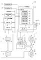
- FIG. 1 is a schematic block diagram showing a vehicle control system according to one embodiment
- FIG. 2 is a perspective view of a shift-by-wire system according to one embodiment
- FIG. 3 is a flowchart illustrating an abnormality monitoring process according to an embodiment
- FIG. 4 is an explanatory diagram for explaining a failsafe procedure according to one embodiment
- FIG. 5 is a flowchart illustrating power control processing in the SBW-ECU according to one embodiment
- FIG. 6 is a flowchart illustrating the power control process in the brake control unit according to one embodiment
- FIG. 7 is a time chart explaining the power control process according to one embodiment.
- the vehicle control device 100 controls the vehicle control system 1, and the vehicle control system 1 includes a shift by wire system 2 as a shift range switching system and an electric brake system 3. Is included.
- the electric brake system 3 includes a brake by wire device 61 and an electric parking brake device 62.
- SBW shift-by-wire
- BBW brake-by-wire
- EPB electric parking brake
- the shift-by-wire system 2 includes a motor 10 as a shift actuator, a shift range switching mechanism 20, a parking lock mechanism 30, and the like.
- the motor 10 is rotated when power is supplied from a battery (not shown) mounted on the vehicle, and functions as a drive source of the shift range switching mechanism 20.
- the encoder 13 detects the rotational position of a not-shown rotor of the motor 10.
- the encoder 13 is, for example, a magnetic rotary encoder, and includes a magnet that rotates integrally with the rotor, and a Hall IC for magnetic detection.
- the encoder 13 outputs A-phase and B-phase pulse signals at predetermined angles in synchronization with the rotation of the rotor.
- the reduction gear 14 is provided between the motor shaft of the motor 10 and the output shaft 15, and decelerates the rotation of the motor 10 and outputs it to the output shaft 15. Thus, the rotation of the motor 10 is transmitted to the shift range switching mechanism 20.
- the output shaft 15 is provided with an output shaft sensor 16 that detects the angle of the output shaft 15.
- the output shaft sensor 16 is, for example, a potentiometer.
- the shift range switching mechanism 20 has a detent plate 21 and a detent spring 25 and the like, and the rotational driving force output from the reduction gear 14 is a manual valve 28 and a parking lock mechanism 30. Transmit to The detent plate 21 is fixed to the output shaft 15 and driven by the motor 10.
- the detent plate 21 is provided with a pin 24 projecting in parallel with the output shaft 15.
- the pin 24 is connected to the manual valve 28.
- the shift range switching mechanism 20 converts the rotational movement of the motor 10 into a linear movement and transmits it to the manual valve 28.
- the manual valve 28 is provided on the valve body 29. The manual valve 28 reciprocates in the axial direction, thereby switching the hydraulic pressure supply path to the hydraulic clutch (not shown), and switching the engagement state of the hydraulic clutch changes the shift range.
- the recess 22 corresponds to each range of D (drive), N (neutral), R (reverse), and P (parking) from the base side of the detent spring 25.
- the detent spring 25 is an elastically deformable plate-like member, and the detent roller 26 is provided at the tip.
- the detent roller 26 fits into any of the recesses 22.
- the detent spring 25 biases the detent roller 26 toward the rotation center of the detent plate 21.
- the detent spring 25 elastically deforms and the detent roller 26 moves in the recess 22.
- the parking lock mechanism 30 has a parking rod 31, a cone 32, a parking lock pole 33, a shaft 34 and a parking gear 35.
- the parking rod 31 is formed in a substantially L-shape, and one end 311 side is fixed to the detent plate 21.
- a conical body 32 is provided on the other end 312 side of the parking rod 31.
- the conical body 32 is formed to decrease in diameter toward the other end 312 side.
- the parking lock pole 33 abuts on the conical surface of the conical body 32 and is provided so as to be able to pivot about the shaft 34.
- a protrusion capable of meshing with the parking gear 35 on the parking gear 35 side of the parking lock pole 33 331 are provided.
- the parking gear 35 is provided on the axle 95 (see FIG. 1) and is provided to be able to mesh with the convex portion 331 of the parking lock pole 33.
- the rotation of the axle 95 is restricted by the engagement of the parking gear 35 and the projection 331.
- the shift range is the NotP range which is a range other than P
- the parking gear 35 is not locked by the parking lock pole 33, and the rotation of the axle 95 is not blocked by the parking lock mechanism 30.
- the shift range is the P range
- the parking gear 35 is locked by the parking lock pole 33, and the rotation of the axle 95 is restricted.
- a predetermined speed for example, 4 [km / h]
- the electric brake system 3 includes a BBW device 61, an EPB device 62, a BBW actuator 65, an EPB actuator 66, and the like.
- the BBW device 61 is provided to the front wheel 91 and the rear wheel 92.
- the BBW device 61 is, for example, a disk brake, and generates braking force by sandwiching a brake rotor that rotates with the front wheel 91 or the rear wheel 92 with brake pads from both sides using a brake caliper.
- the EPB device 62 is provided on the rear wheel 92.
- the EPB device 62 is, for example, a drum brake and is incorporated in the BBW device 61.
- the BBW actuator 65 causes the BBW device 61 to perform braking on the basis of a command from the BBW-ECU 71 described later.
- the BBW actuator 65 has a motor, and operates the brake caliper by driving the motor.
- the BBW actuator 65 has a pump motor, an electric hydraulic pump, a hydraulic booster, and a solenoid valve, and increases hydraulic pressure generated by driving the electric hydraulic pump by the pump motor with the hydraulic booster. The hydraulic pressure that has been adjusted at the above is supplied to the BBW device 61.
- the BBW actuator 65 is provided for each of the front wheel 91 and the rear wheel 92 in FIG. 1, for example, a hydraulic circuit or the like may be shared.
- the EPB actuator 66 causes the EPB device 62 to perform braking based on a command from the EPB-ECU 72 described later.
- the ratchet mechanism maintains the braking state even after the EPB actuator 66 is deenergized. Further, the braking state is released by performing the releasing operation according to the command from the EPB-ECU 72.
- the BBW actuator 65 and the EPB actuator 66 correspond to a "brake actuator".
- the vehicle control device 100 includes a shift range control device 40 and a brake control device 70.
- the shift range control device 40 has a motor driver 41, an SBW-ECU 50, and the like.
- the motor driver 41 has a switching element (not shown), and switches the energization of the motor 10 by turning on and off the switching element based on a command from the SBW-ECU 50. Thereby, the drive of the motor 10 is controlled.
- a motor relay 42 is provided between the motor driver 41 and the battery. By controlling the on / off operation of the motor relay 42, it is possible to switch permission or prohibition of energization from the battery to the motor 10 side.
- the SBW-ECU 50 has a drive control unit 51, a solenoid control unit 52, an abnormality monitoring unit 53, a presence determination unit 54, a braking command unit 55, a notification command unit 56, and the like.
- the drive control unit 51 controls switching of the shift range by controlling the driving of the motor 10 based on the driver request shift range, the signal from the brake switch, the vehicle speed, and the like. Specifically, the drive control unit 51 drives the motor 10 by feedback control or the like so that the motor angle ⁇ m, which is the rotation angle of the motor 10, stops at the target angle ⁇ cmd set according to the required shift range. Control.
- the details of the drive control of the motor 10 may be arbitrary.
- the solenoid control unit 52 controls the driving of the shifting hydraulic control solenoid 6 based on the vehicle speed, the accelerator opening degree, the driver's requested shift range, and the like. By controlling the shift hydraulic control solenoid 6, the gear is controlled.
- the transmission hydraulic control solenoid 6 is provided in a number corresponding to the number of shift stages and the like.
- the solenoid control unit 52 is provided in the SBW-ECU 50, and the SBW-ECU 50 controls the motor 10 and the solenoid 6.
- the AT-ECU may be configured to have the solenoid control unit 52 separately from the AT-ECU.
- the abnormality monitoring unit 53 monitors an abnormality of the shift by wire system 2.
- the presence determination unit 54 determines whether the driver is at the driver's seat based on information such as a weight sensor, a seat belt sensor, and a door open / close detection sensor provided at the driver's seat. The details of the presence determination may be arbitrary.
- the braking command unit 55 instructs the brake control device 70 to brake the vehicle by the electric brake system 3.
- the notification command unit 56 instructs notification of information indicating that the shift by wire system 2 has an abnormality.
- the notification command unit 56 instructs the inside warning unit 81 and the outside notification unit 82 to issue a notification.
- notification command unit 56 notifies other ECUs, such as a host ECU (not shown), that there is an abnormality in shift-by-wire system 2 via vehicle communication network 79, and the other ECUs warn in the vehicle
- the unit 81 and the outside-of-vehicle notification unit 82 may be operated.
- the brake control device 70 includes a BBW-ECU 71, an EPB-ECU 72, and the like.
- the BBW-ECU 71 controls the braking force or the like of the BBW device 61 by controlling the BBW actuator 65 in accordance with the operation amount or the like of the brake pedal (not shown).
- the EPB-ECU 72 controls the EPB actuator 66 to control braking and release of braking by the EPB device 62.
- the automatic parking ECU 75 controls the drive of the vehicle by controlling the shift-by-wire system 2, the electric brake system 3, a vehicle drive system (not shown) including an engine and a main machine motor, and an electric steering system (not shown). Do automatic parking.
- Each of the ECUs 50, 71, 72, 75 is mainly composed of a microcomputer or the like, and includes a CPU, a ROM, a RAM, an I / O, and a bus line connecting these components, all of which are not shown. There is.
- Each processing in the ECUs 50, 71, 72, 75 is software processing by the CPU executing a program stored in advance in a tangible memory device (i.e., readable non-transitory tangible recording medium) such as a ROM. It may be hardware processing with a dedicated electronic circuit. Further, each processing in the ECUs 50, 71, 72, 75 may be executed by an ECU different from the ECU described as the execution subject in the present specification. Also, several ECUs may be integrated into one ECU.
- the ECUs 50, 71, 72, 75 are activated when a start switch such as an ignition switch is turned on.
- a start switch such as an ignition switch
- the ECUs 50, 71, 72, 75 can mutually exchange information via a vehicle communication network 79 which is, for example, a CAN (Controller Area Network), and at the same time, the driver request shift range, brake switch, accelerator opening, vehicle speed, driver It is possible to acquire various types of vehicle information including the state of the seating detection switch and the like.
- These pieces of information may be configured to be acquired directly by the ECUs 50, 71, 72, 75 without passing through the vehicle communication network 79.
- some control lines etc. such as a control line to one side of rear wheel 92, were omitted.
- the in-vehicle warning unit 81 notifies the driver in the vehicle that the shift-by-wire system 2 is abnormal.
- the method of notifying the driver may be, for example, warning display on an instrument panel or the like, lighting of a warning lamp, notification by sound, or the like.
- the outside-of-vehicle notification unit 82 notifies the outside of the vehicle that the shift-by-wire system 2 is abnormal.
- the method of notifying the outside of the vehicle is, for example, a notification by a buzzer sound outside the vehicle. Further, for example, notification to a communication key such as a vehicle key or a smartphone of a driver may be used.
- the vehicle control system 1 of the present embodiment includes an automatic parking function of automatically parking the shift-by-wire system 2, the electric brake system 3, the vehicle drive system, the electric steering system, and the like.
- an automatic parking function of automatically parking the shift-by-wire system 2, the electric brake system 3, the vehicle drive system, the electric steering system, and the like.
- the parking brake The driver was warned that the vehicle was to be operated, and the driver could secure the safety by operating the parking brake.
- the automatic parking function when the automatic parking function is provided, remote parking is possible, in which the driver gets off the vehicle and instructs parking from the outside of the vehicle. If an abnormality occurs in the shift-by-wire system 2 while the driver is absent, there is a possibility that the driver can not be notified of the abnormality even if, for example, a warning is displayed on the instrument panel or the like.
- step S101 when an abnormality occurs in the shift by wire system 2, different fail safe measures are performed depending on whether the driver is present or not present.
- the abnormality monitoring process of the present embodiment will be described based on the flowchart of FIG. This process is executed by SBW-ECU 50 at a predetermined cycle.
- step S101 is omitted and simply referred to as the symbol “S”.
- the abnormality monitoring unit 53 determines whether a range mismatch time in which the target shift range and the actual range do not match is equal to or greater than the determination time Xth.
- the actual range is an actual shift range, and corresponds to the recess 22 in which the detent roller 26 is fitted. In other words, the actual range corresponds to the rotational position of the output shaft 15.
- the determination time Xth is set to a time (e.g., 0.5 [ms]) sufficiently longer than the time required for range switching. If it is determined that the range mismatch time is less than the determination time Xth (S101: NO), the shift by wire system 2 is considered to be normal, and the process of S102 is not performed.
- the drive of the motor 10 is stopped by turning off the motor relay 42 as a fail safe treatment regardless of the presence condition and the range of the driver. Further, the in-vehicle warning unit 81 notifies the in-vehicle of the abnormality of the shift by wire system 2.
- the target range is the P range and the actual range is the P range
- the target range and the actual range match and are normal, so fail-safe processing is not performed.
- the target range is the R range and the actual range is the R range
- the target range is the D range and the actual range is the D range
- the target range and the actual range match and are normal. Do not take safe action.
- the parking lock mechanism 30 can not be locked, resulting in a P impossible abnormality, which may cause the vehicle to run backward as an influence on the vehicle.
- the target range is the P range and the actual range is the D range
- the P is not normal and the vehicle may run away as an influence on the vehicle.
- the solenoid control unit 52 controls the solenoid 6 to force the automatic transmission 5 into the neutral state. Make it In addition, by warning the interior of the vehicle, the driver is urged to operate the parking brake.
- the target range is the P range and the actual range is the N range, it is a P-impaired state, and there is a risk that the vehicle may fall downhill on a slope as an influence on the vehicle.
- the actual range is N range, no forced neutral action is necessary.
- the SBW-ECU 50 adds the BBW- to the forced neutral measures of the automatic transmission 5 similar to the driver presence.
- the ECU 71 is instructed to operate the brake by the BBW device 61.
- the notification command unit 56 instructs the outside notification unit 82 to notify the abnormality of the shift by wire system 2 to the outside of the vehicle.
- the SBW-ECU 50 instructs the BBW-ECU 71 to operate the brake by the BBW device 61. Further, the notification command unit 56 instructs the outside notification unit 82 to notify the abnormality of the shift by wire system 2 to the outside of the vehicle.
- the vehicle travels in the opposite direction to the direction intended by the driver as the influence on the vehicle.
- the target range is the R range and the actual range is the D range
- the target range is the D range and the actual range is the R range and the driver is present, forced neutral processing is performed.
- the target range is the R range or the D range
- the actual range is the N range
- the actual range is N range, no forced neutral action is necessary.
- the target range is the R range or D range and the actual range is the P range
- ratchet noise generated by flipping the cone 32 of the parking lock mechanism 30 occurs at high speed as an influence on the vehicle There is a risk.
- the target range is the R range or the D range
- the actual range is the P range, and the driver is present, forced neutral processing is performed.
- the target range is the R range and the actual range is the D range or P range
- driving is performed.
- the SBW-ECU 50 instructs the BBW-ECU 71 to perform the brake operation by the BBW device 61, in addition to the forced neutral processing of the automatic transmission 5 similar to that when the user is present.
- the SBW-ECU 50 instructs the BBW-ECU 71 to operate the brake by the BBW device 61. .
- the notification instruction unit 56 instructs the outside notification unit 82 to notify the outside of the vehicle of the abnormality of the shift by wire system 2.
- the target range is the R range or the D range, and at least one of the BBW operation in the absence of the driver and the notification to the outside of the vehicle may be omitted.
- the vehicle when there is a P-impaired abnormality in which the shift range can not be switched to the P range while the driver is absent, such as during automatic parking, the vehicle may be fixed by the parking lock mechanism 30 of the shift by wire system 2 There is a possibility that the vehicle may slip down or the like. Therefore, in the present embodiment, when a P-impaired abnormality occurs in the driver absent state, the BBW device 61 is operated by a command from the braking command unit 55 of the SBW-ECU 50 to fix the vehicle. That is, in the present embodiment, it can be said that the fail-safe treatment is performed by coordinating the shift-by-wire system 2 and the electric brake system 3. As a result, even when an abnormality occurs in the shift by wire system 2 when the driver is absent, it is possible to prevent an unintended operation such as a slippage of the vehicle after the parking is completed.
- the ECUs 50, 71, 72, 75 are turned off after executing the shutdown processing or the like.
- the BBW-ECU 71 and the EPB-ECU 72 are turned off before P is completed in the shift-by-wire system 2, and if P becomes impossible after the ECUs 71 and 72 are turned off, the vehicle is fixed by the electric brake system 3. I can not Therefore, in the present embodiment, the BBW-ECU 71 and the EPB-ECU 72 are turned off after the SBW-ECU 50 is turned off.
- the power control process in the SBW-ECU 50 will be described based on the flowchart of FIG. This process is executed by SBW-ECU 50 at a predetermined cycle.
- the SBW-ECU 50 determines whether the IG is turned off. If it is determined that the IG is not turned off (S201: NO), the process proceeds to S202, and the on state of the shift by wire system 2 is continued.
- the SBW-ECU 50 performs range switching control in accordance with an instruction from the automatic parking ECU 75 or the shifter. If it is determined that the IG is turned off (S201: YES), the process proceeds to S204.
- the SBW-ECU 50 determines whether the actual range is the P range. If it is determined that the actual range is the P range (S204: YES), the process proceeds to S205, and the brake control device 70 is notified of information that P operation has been completed. The notification to the brake control device 70 is performed to at least one of the BBW-ECU 71 and the EPB-ECU 72. When it is determined that the P operation is not completed (S204: NO), the process proceeds to S206, and the drive control unit 51 controls the motor 10 so that the actual range becomes the P range.
- the abnormality monitoring unit 53 determines whether the determination time Xth has elapsed after the P operation command. If it is determined that the determination time Xth has not elapsed (S207: NO), the process returns to S204. If it is determined that the determination time Xth has elapsed (S207: YES), the process proceeds to S208, in which it is determined that a P-impaired abnormality has occurred, and the failsafe procedure for P-impairment abnormality described in FIG. Ru.
- the power control process in the brake control device 70 will be described based on the flowchart of FIG. This process is executed by the brake control device 70 at a predetermined cycle.
- the processing in which the action subject is described as the brake control device 70 is executed by at least one of the BBW-ECU 71 and the EPB-ECU 72.
- the brake control device 70 determines whether or not the IG is turned off. If it is determined that the IG is not turned off (S301: NO), the process proceeds to S302, and the on state of the brake-by-wire system and the electric parking brake system is continued. In S303, the brake control device 70 performs the brake control according to the depression amount of the brake pedal, the command from the ECU 75 for automatic parking, and the like.
- the brake control device 70 determines whether P operation has been completed in the shift by wire system 2. The completion of the P operation is determined based on the P operation completion notification transmitted from the SBW-ECU 50. If it is determined that the P operation has been completed (S304: YES), the process proceeds to S306. If it is determined that the P operation is not completed (S304: NO), the process proceeds to S305.
- the brake control device 70 determines whether the determination time Xth has elapsed after the P actuation command.
- the determination may be made by counting on the brake control device 70 side, or when information indicating that a P impossible abnormality has occurred is received from the SBW-ECU 50, it is determined that the determination time Xth has elapsed. It is also good. If it is determined that the determination time Xth has not elapsed (S305: NO), the processing of S306 to S308 is not performed, and the on state of the electric brake system 3 is continued. If it is determined that the determination time Xth has elapsed (S305: YES), the process proceeds to S306.
- the EPB-ECU 72 drives the EPB actuator 66 to operate the EPB device 62. After the operation of the EPB device 62 is completed, the EPB actuator 66 is turned off.
- the EPB-ECU 72 turns off the EPB-ECU 72 after the shutdown process. As described above, when the EPB device 62 is operated, the braking state after the off is continued until the braking release process is performed.
- the BBW-ECU 71 turns off the BBW actuator 65, and turns off the BBW-ECU 71 after the shutdown process.
- the horizontal axis represents the common time axis, and from the top, vehicle speed, IG on / off state, automatic parking control on / off state, SBW control, SBW-ECU 50 on / off state, BBW-ECU 71 on / off state, EPB-ECU 72 On and off states as well as EPB control are shown.
- the shift-by-wire system 2 operates normally until time x11, and a P impossible abnormality is detected when switching the shift range to the P range at time x11.
- the time scale is appropriately changed for the sake of explanation, and does not necessarily coincide with the actual.
- the time which a shutdown process requires was abbreviate
- Automatic parking control is executed at time x10 according to a command from the driver. During automatic parking control, switching of the shift range is repeated to park the vehicle at a desired location. In FIG. 7, the range is switched from R to D to R, but the number of times of turning back, the duration of each range, and the like do not matter.
- the target shift range is switched to the P range as indicated by the one-dot chain line.
- switching to the P range is performed at a timing before the determination time Xth elapses.
- ECU 75 for automatic parking instructs switching to P range, and then IG May be turned off, or switching to the P range may be commanded using IG off as a trigger, and the control order does not matter.
- the EPB apparatus at time x12 when the determination time Xth has elapsed from time x11 Activate 62. Further, at time x13 after the completion of the operation of the EPB device 62, the EPB control is ended, and after the shutdown processing, the EPB-ECU 72 is turned off. Also, at time x14 after the EPB-ECU 72 is turned off, the BBW-ECU 71 is turned off.
- FIG. 7 describes the P-impossible abnormality, the power is turned off in the order of SBW-ECU 50, EPB-ECU 72, and BBW-ECU 71 in this embodiment regardless of the presence or absence of range mismatch abnormality.
- control is performed according to a command from the EUC 75 for automatic parking.
- the BBW control end timing may be simultaneous with the time x13 when the EPB control ends, or may be any time after the time x13 and before the time x14 when the BBW-ECU 71 is turned off.
- the vehicle control device 100 of the present embodiment controls the vehicle control system 1 including the shift by wire system 2 and the electric brake system 3.
- the shift by wire system 2 switches the shift range by controlling the drive of the motor 10.
- the electric brake system 3 brakes the vehicle by controlling the driving of the BBW actuator 65 and the EPB actuator 66.
- the vehicle control device 100 includes a shift control unit and a brake control unit.
- the SBW-ECU 50 which is a shift control unit, controls the drive of the motor 10.
- the BBW-ECU 71 which is a brake control unit, controls the drive of the BBW actuator 65, which is a brake actuator.
- the EPB-ECU 72 which is a brake control unit, controls the drive of the EPB actuator 66, which is a brake actuator.
- the vehicle can not be fixed by the shift-by-wire system 2, and the vehicle may be slipped down. Therefore, in the present embodiment, the power of the BBW-ECU 71 and the EPB-ECU 72 is turned off after the shift-by-wire system 2 is switched to the P range. In other words, the BBW-ECU 71 and the EPB-ECU 72 are not turned off until the P insertion of the shift by wire system 2 is completed. As a result, when a P-impaired abnormality occurs, the vehicle can be fixed securely by the electric brake system 3, so that the safety in the case where an abnormality occurs in the shift-by-wire system 2 can be improved.
- the powers of BBW-ECU 71 and EPB-ECU 72 are turned off.
- the power is turned off in order of the SBW-ECU 50, the EPB-ECU 72, and the BBW-ECU 71.
- the electric brake system 3 has an EPB device 62 capable of maintaining the braking state even after the power-off.
- the EPB device 62 When a P-impaired abnormality that makes it impossible to switch to the P range in the shift-by-wire system 2 occurs, the EPB device 62 is operated, and then the power of the BBW-ECU 71 and the EPB-ECU 72 is turned off. As a result, even when the P impossibility has occurred, the vehicle can be fixed securely.
- the BBW device 61 when a range mismatch abnormality occurs, the BBW device 61 is operated to fix the vehicle.
- the EPB device 62 may be activated when a range mismatch abnormality occurs.
- the EPB device 62 instead of the BBW device 61, the EPB device 62 may be operated.
- the electric brake system includes the BBW system and the EPB system, but either one may be mechanical. Further, the electric brake system is not limited to the configuration of the above embodiment as long as the brake control device can control the braking, and any configuration may be used.
- the shift switching system is normal when the IG is turned off, the power is turned off in the SBW-ECU 50, the power in the EPB-ECU 72 is turned off, and the power in the BBW-ECU 71 is turned off.
- the power of the brake control unit may be turned off after completion of switching to the P range in the shift-by-wire system or completion of vehicle fixation by the electric brake system, and the control sequence described above may be performed. May be different.
- the BBW-ECU may be continued to operate without powering off the BBW-ECU.
- the SBW-ECU, the BBW-ECU, and the EPB-ECU are provided as separate ECUs. In another embodiment, at least a part of these may be provided as one ECU. In this case, transmission and reception of various information may be performed internally without passing through the vehicle communication network.
- the motor rotation angle sensor is an encoder. In another embodiment, the motor rotation angle sensor is not limited to the encoder, and any sensor such as a resolver may be used. In the above embodiment, a potentiometer is illustrated as an output axis sensor. In other embodiments, the output shaft sensor may be of any type, for example, may be constituted by a switch turned on in each range guaranteeing area, or a non-contact magnetic sensor may be used. Good. Also, the output shaft sensor may be omitted.
- the detent plate is provided with four valleys.
- the number of valleys is not limited to four, but may be any number.
- two valleys corresponding to the P range and the not P range which is a range other than the P range may be provided.
- the shift range switching mechanism, the parking lock mechanism, etc. may be different from the above embodiment.
- a reduction gear is provided between the motor shaft and the output shaft.
- the details of the reduction gear are not mentioned in the above embodiment, for example, a cycloid gear, a planetary gear, a spur gear that transmits torque from the reduction mechanism substantially coaxial with the motor shaft to the drive shaft, or these Any configuration may be used, such as one using a combination of
- the reduction gear between the motor shaft and the output shaft may be omitted, or a mechanism other than the reduction gear may be provided.
- this indication is not limited at all to the above-mentioned embodiment, and can be carried out in various forms in the range which does not deviate from the meaning.
Landscapes
- Engineering & Computer Science (AREA)
- Mechanical Engineering (AREA)
- General Engineering & Computer Science (AREA)
- Transportation (AREA)
- Regulating Braking Force (AREA)
- Gear-Shifting Mechanisms (AREA)
- Valves And Accessory Devices For Braking Systems (AREA)
- Control Of Transmission Device (AREA)
Abstract
This vehicle control device (100) controls a vehicle control system (1) which includes a shift range switching system (2) for switching the shift range by controlling driving of a shift actuator (10) and an electric brake system (3) for braking the vehicle by controlling driving of a brake actuator (65, 66), and is provided with a shift control unit (50) and a brake control unit (71, 72). The shift control unit (50) controls driving of the shift actuator (10). The brake control unit (71, 72) controls driving of the brake actuator (65, 66). If the start switch of the vehicle is OFF, then, after the shift range switching system (2) has completed switching to the P range, the power supply of the brake control unit (71, 72) is turned OFF.
Description
本出願は、2017年11月24日に出願された特許出願番号2017-226017号に基づくものであり、ここにその記載内容を援用する。
This application is based on patent application number 2017-226017 filed on November 24, 2017, the contents of which are incorporated herein by reference.
本開示は、車両用制御装置に関する。
The present disclosure relates to a control device for a vehicle.
従来、運転者からのシフトレンジ切替要求に応じてモータを制御することでシフトレンジを切り替えるシフトレンジ切替装置が知られている。例えば特許文献1では、異常診断により、エンコーダ異常、出力軸センサ異常、その他の異常を区別して診断している。
BACKGROUND Conventionally, a shift range switching device is known that switches a shift range by controlling a motor according to a shift range switching request from a driver. For example, in patent document 1, an encoder abnormality, an output axis sensor abnormality, and other abnormalities are distinguished and diagnosed by abnormality diagnosis.
特許文献1では、シフトレンジ切替装置において異常が検出されたとき、警告ランプの点灯やインスツルメントパネルへの警告表示などにより、運転者に異常を通知している。しかしながら、シフトレンジ切替装置の異常発生時に、他のシステムをどのように制御するかについては、何ら言及されていない。本開示の目的は、シフトレンジ切替システムに異常が生じた場合の安全性を向上可能である車両用制御装置を提供することにある。
In Patent Document 1, when an abnormality is detected in the shift range switching device, the driver is notified of the abnormality by lighting a warning lamp or displaying a warning on the instrument panel. However, no mention is made as to how to control other systems when an abnormality occurs in the shift range switching device. An object of the present disclosure is to provide a control device for a vehicle that can improve the safety when a shift range switching system has an abnormality.
本開示の車両用制御装置は、シフトレンジ切替システムおよび電動ブレーキシステムを含む車両制御システムを制御する。シフトレンジ切替システムは、シフトアクチュエータの駆動を制御することでシフトレンジを切り替える。電動ブレーキシステムは、ブレーキアクチュエータの駆動を制御することで車両を制動させる。
The vehicle control device of the present disclosure controls a vehicle control system including a shift range switching system and an electric brake system. The shift range switching system switches the shift range by controlling the drive of the shift actuator. The electric brake system brakes the vehicle by controlling the drive of the brake actuator.
車両用制御装置は、シフトアクチュエータの駆動を制御するシフト制御部と、ブレーキアクチュエータの駆動を制御するブレーキ制御部と、を備える。車両の始動スイッチがオフされた場合、シフトレンジ切替システムのPレンジへの切替完了後、ブレーキ制御部の電源をオフにする。
The vehicle control device includes a shift control unit that controls the drive of the shift actuator, and a brake control unit that controls the drive of the brake actuator. If the start switch of the vehicle is turned off, the power of the brake control unit is turned off after the shift range switching system has been switched to the P range.
換言すると、シフトレンジ切替システムにてPレンジへの切り替えが完了するまでは、ブレーキ制御部の電源をオンにしておく。これにより、例えばシフトレンジ切替システムにてPレンジへの切り替えが不能となるP不可異常が発生した場合、電動ブレーキシステムによる車両固定を確実に行うことができ、シフトレンジ切替システムに異常が生じた場合の安全性を向上可能である。
In other words, the power of the brake control unit is turned on until the switching to the P range is completed in the shift range switching system. As a result, for example, when a P-impaired abnormality that makes it impossible to switch to the P range in the shift range switching system occurs, the vehicle can be reliably fixed by the electric brake system, and an abnormality occurs in the shift range switching system The safety of the case can be improved.
本開示についての上記目的及びその他の目的、特徴や利点は、添付の図面を参照しながら下記の詳細な記述により、より明確になる。その図面は、
図1は、一実施形態による車両制御システムを示す概略構成図であり、
図2は、一実施形態によるシフトバイワイヤシステムを示す斜視図であり、
図3は、一実施形態による異常監視処理を説明するフローチャートであり、
図4は、一実施形態によるフェイルセーフ処置を説明する説明図であり、
図5は、一実施形態によるSBW-ECUにおける電源制御処理を説明するフローチャートであり、
図6は、一実施形態によるブレーキ制御部における電源制御処理を説明するフローチャートであり、
図7は、一実施形態による電源制御処理を説明するタイムチャートである。
The above object and other objects, features and advantages of the present disclosure will become more apparent from the following detailed description with reference to the attached drawings. The drawing is
FIG. 1 is a schematic block diagram showing a vehicle control system according to one embodiment; FIG. 2 is a perspective view of a shift-by-wire system according to one embodiment; FIG. 3 is a flowchart illustrating an abnormality monitoring process according to an embodiment; FIG. 4 is an explanatory diagram for explaining a failsafe procedure according to one embodiment; FIG. 5 is a flowchart illustrating power control processing in the SBW-ECU according to one embodiment; FIG. 6 is a flowchart illustrating the power control process in the brake control unit according to one embodiment; FIG. 7 is a time chart explaining the power control process according to one embodiment.
(一実施形態)
以下、本開示による車両用制御装置を図面に基づいて説明する。図1に示すように、車両用制御装置100は、車両制御システム1を制御するものであって、車両制御システム1には、シフトレンジ切替システムとしてのシフトバイワイヤシステム2、および、電動ブレーキシステム3が含まれる。電動ブレーキシステム3には、ブレーキバイワイヤ装置61および電動パーキングブレーキ装置62が含まれる。以下適宜、シフトバイワイヤを「SBW」、ブレーキバイワイヤを「BBW」、電動パーキングブレーキを「EPB」と記載する。 (One embodiment)
Hereinafter, a vehicle control device according to the present disclosure will be described based on the drawings. As shown in FIG. 1, thevehicle control device 100 controls the vehicle control system 1, and the vehicle control system 1 includes a shift by wire system 2 as a shift range switching system and an electric brake system 3. Is included. The electric brake system 3 includes a brake by wire device 61 and an electric parking brake device 62. Hereinafter, the shift-by-wire is described as “SBW”, the brake-by-wire as “BBW”, and the electric parking brake as “EPB”.
以下、本開示による車両用制御装置を図面に基づいて説明する。図1に示すように、車両用制御装置100は、車両制御システム1を制御するものであって、車両制御システム1には、シフトレンジ切替システムとしてのシフトバイワイヤシステム2、および、電動ブレーキシステム3が含まれる。電動ブレーキシステム3には、ブレーキバイワイヤ装置61および電動パーキングブレーキ装置62が含まれる。以下適宜、シフトバイワイヤを「SBW」、ブレーキバイワイヤを「BBW」、電動パーキングブレーキを「EPB」と記載する。 (One embodiment)
Hereinafter, a vehicle control device according to the present disclosure will be described based on the drawings. As shown in FIG. 1, the
図1および図2に示すように、シフトバイワイヤシステム2は、シフトアクチュエータとしてのモータ10、シフトレンジ切替機構20、および、パーキングロック機構30等を備える。モータ10は、車両に搭載される図示しないバッテリから電力が供給されることで回転し、シフトレンジ切替機構20の駆動源として機能する。
As shown in FIGS. 1 and 2, the shift-by-wire system 2 includes a motor 10 as a shift actuator, a shift range switching mechanism 20, a parking lock mechanism 30, and the like. The motor 10 is rotated when power is supplied from a battery (not shown) mounted on the vehicle, and functions as a drive source of the shift range switching mechanism 20.
エンコーダ13は、モータ10の図示しないロータの回転位置を検出する。エンコーダ13は、例えば磁気式のロータリーエンコーダであって、ロータと一体に回転する磁石と、磁気検出用のホールIC等により構成される。エンコーダ13は、ロータの回転に同期して、所定角度ごとにA相およびB相のパルス信号を出力する。
The encoder 13 detects the rotational position of a not-shown rotor of the motor 10. The encoder 13 is, for example, a magnetic rotary encoder, and includes a magnet that rotates integrally with the rotor, and a Hall IC for magnetic detection. The encoder 13 outputs A-phase and B-phase pulse signals at predetermined angles in synchronization with the rotation of the rotor.
減速機14は、モータ10のモータ軸と出力軸15との間に設けられ、モータ10の回転を減速して出力軸15に出力する。これにより、モータ10の回転がシフトレンジ切替機構20に伝達される。出力軸15には、出力軸15の角度を検出する出力軸センサ16が設けられる。出力軸センサ16は、例えばポテンショメータである。
The reduction gear 14 is provided between the motor shaft of the motor 10 and the output shaft 15, and decelerates the rotation of the motor 10 and outputs it to the output shaft 15. Thus, the rotation of the motor 10 is transmitted to the shift range switching mechanism 20. The output shaft 15 is provided with an output shaft sensor 16 that detects the angle of the output shaft 15. The output shaft sensor 16 is, for example, a potentiometer.
図2に示すように、シフトレンジ切替機構20は、ディテントプレート21、および、ディテントスプリング25等を有し、減速機14から出力された回転駆動力を、マニュアルバルブ28、および、パーキングロック機構30へ伝達する。ディテントプレート21は、出力軸15に固定され、モータ10により駆動される。
As shown in FIG. 2, the shift range switching mechanism 20 has a detent plate 21 and a detent spring 25 and the like, and the rotational driving force output from the reduction gear 14 is a manual valve 28 and a parking lock mechanism 30. Transmit to The detent plate 21 is fixed to the output shaft 15 and driven by the motor 10.
ディテントプレート21には、出力軸15と平行に突出するピン24が設けられる。ピン24は、マニュアルバルブ28と接続される。ディテントプレート21がモータ10によって駆動されることで、マニュアルバルブ28は軸方向に往復移動する。すなわち、シフトレンジ切替機構20は、モータ10の回転運動を直線運動に変換してマニュアルバルブ28に伝達する。マニュアルバルブ28は、バルブボディ29に設けられる。マニュアルバルブ28が軸方向に往復移動することで、図示しない油圧クラッチへの油圧供給路が切り替えられ、油圧クラッチの係合状態が切り替わることでシフトレンジが変更される。
The detent plate 21 is provided with a pin 24 projecting in parallel with the output shaft 15. The pin 24 is connected to the manual valve 28. When the detent plate 21 is driven by the motor 10, the manual valve 28 reciprocates in the axial direction. That is, the shift range switching mechanism 20 converts the rotational movement of the motor 10 into a linear movement and transmits it to the manual valve 28. The manual valve 28 is provided on the valve body 29. The manual valve 28 reciprocates in the axial direction, thereby switching the hydraulic pressure supply path to the hydraulic clutch (not shown), and switching the engagement state of the hydraulic clutch changes the shift range.
ディテントプレート21のディテントスプリング25側には、マニュアルバルブ28を各レンジに対応する位置に保持するための4つの凹部22が設けられる。凹部22は、ディテントスプリング25の基部側から、D(ドライブ)、N(ニュートラル)、R(リバース)、P(パーキング)の各レンジに対応している。
On the detent spring 25 side of the detent plate 21, four recesses 22 for holding the manual valve 28 at positions corresponding to the respective ranges are provided. The recess 22 corresponds to each range of D (drive), N (neutral), R (reverse), and P (parking) from the base side of the detent spring 25.
ディテントスプリング25は、弾性変形可能な板状部材であり、先端にディテントローラ26が設けられる。ディテントローラ26は、凹部22のいずれかに嵌まり込む。ディテントスプリング25は、ディテントローラ26をディテントプレート21の回動中心側に付勢する。ディテントプレート21に所定以上の回転力が加わると、ディテントスプリング25が弾性変形し、ディテントローラ26が凹部22を移動する。ディテントローラ26が凹部22のいずれかに嵌まり込むことで、ディテントプレート21の揺動が規制され、マニュアルバルブ28の軸方向位置、および、パーキングロック機構30の状態が決定され、自動変速機5のシフトレンジが固定される。
The detent spring 25 is an elastically deformable plate-like member, and the detent roller 26 is provided at the tip. The detent roller 26 fits into any of the recesses 22. The detent spring 25 biases the detent roller 26 toward the rotation center of the detent plate 21. When a rotational force of a predetermined value or more is applied to the detent plate 21, the detent spring 25 elastically deforms and the detent roller 26 moves in the recess 22. By the detent roller 26 being fitted in any of the recessed portions 22, the swing of the detent plate 21 is restricted, the axial position of the manual valve 28 and the state of the parking lock mechanism 30 are determined. The shift range of is fixed.
パーキングロック機構30は、パーキングロッド31、円錐体32、パーキングロックポール33、軸部34、および、パーキングギア35を有する。パーキングロッド31は、略L字形状に形成され、一端311側がディテントプレート21に固定される。パーキングロッド31の他端312側には、円錐体32が設けられる。円錐体32は、他端312側にいくほど縮径するように形成される。ディテントプレート21が逆回転方向に揺動すると、円錐体32が矢印Pの方向に移動する。
The parking lock mechanism 30 has a parking rod 31, a cone 32, a parking lock pole 33, a shaft 34 and a parking gear 35. The parking rod 31 is formed in a substantially L-shape, and one end 311 side is fixed to the detent plate 21. A conical body 32 is provided on the other end 312 side of the parking rod 31. The conical body 32 is formed to decrease in diameter toward the other end 312 side. When the detent plate 21 swings in the reverse rotation direction, the conical body 32 moves in the direction of the arrow P.
パーキングロックポール33は、円錐体32の円錐面と当接し、軸部34を中心に揺動可能に設けられる、パーキングロックポール33のパーキングギア35側には、パーキングギア35と噛み合い可能な凸部331が設けられる。ディテントプレート21が逆回転方向に回転し、円錐体32が矢印P方向に移動すると、パーキングロックポール33が押し上げられ、凸部331とパーキングギア35とが噛み合う。一方、ディテントプレート21が正回転方向に回転し、円錐体32が矢印NotP方向に移動すると、凸部331とパーキングギア35との噛み合いが解除される。
The parking lock pole 33 abuts on the conical surface of the conical body 32 and is provided so as to be able to pivot about the shaft 34. A protrusion capable of meshing with the parking gear 35 on the parking gear 35 side of the parking lock pole 33 331 are provided. When the detent plate 21 rotates in the reverse rotation direction and the cone 32 moves in the arrow P direction, the parking lock pole 33 is pushed up, and the convex portion 331 and the parking gear 35 mesh with each other. On the other hand, when the detent plate 21 rotates in the normal rotation direction and the conical body 32 moves in the arrow NotP direction, the engagement between the convex portion 331 and the parking gear 35 is released.
パーキングギア35は、車軸95(図1参照)に設けられ、パーキングロックポール33の凸部331と噛み合い可能に設けられる。パーキングギア35と凸部331とが噛み合うことで、車軸95の回転が規制される。シフトレンジがP以外のレンジであるNotPレンジのとき、パーキングギア35はパーキングロックポール33によりロックされず、車軸95の回転は、パーキングロック機構30により妨げられない。シフトレンジがPレンジのとき、パーキングギア35はパーキングロックポール33によってロックされ、車軸95の回転が規制される。車速が所定速度(例えば4[km/h])以上になると、円錐体32がはじかれ、車軸95がロックされないようになっている。
The parking gear 35 is provided on the axle 95 (see FIG. 1) and is provided to be able to mesh with the convex portion 331 of the parking lock pole 33. The rotation of the axle 95 is restricted by the engagement of the parking gear 35 and the projection 331. When the shift range is the NotP range which is a range other than P, the parking gear 35 is not locked by the parking lock pole 33, and the rotation of the axle 95 is not blocked by the parking lock mechanism 30. When the shift range is the P range, the parking gear 35 is locked by the parking lock pole 33, and the rotation of the axle 95 is restricted. When the vehicle speed becomes equal to or higher than a predetermined speed (for example, 4 [km / h]), the conical body 32 is repelled and the axle 95 is not locked.
図1に示すように、電動ブレーキシステム3は、BBW装置61、EPB装置62、BBWアクチュエータ65、および、EPBアクチュエータ66等を備える。BBW装置61は、前輪91および後輪92に設けられる。BBW装置61は、例えばディスクブレーキであり、前輪91または後輪92とともに回転するブレーキロータを、ブレーキキャリパを用いてブレーキパッドで両側から挟み込むことで制動力を発生させる。EPB装置62は、後輪92に設けられる。EPB装置62は、例えばドラムブレーキであって、BBW装置61に内蔵される。
As shown in FIG. 1, the electric brake system 3 includes a BBW device 61, an EPB device 62, a BBW actuator 65, an EPB actuator 66, and the like. The BBW device 61 is provided to the front wheel 91 and the rear wheel 92. The BBW device 61 is, for example, a disk brake, and generates braking force by sandwiching a brake rotor that rotates with the front wheel 91 or the rear wheel 92 with brake pads from both sides using a brake caliper. The EPB device 62 is provided on the rear wheel 92. The EPB device 62 is, for example, a drum brake and is incorporated in the BBW device 61.
BBWアクチュエータ65は、後述のBBW-ECU71からの指令に基づき、BBW装置61での制動を行わせる。例えば、BBWアクチュエータ65は、モータを有しており、モータを駆動することでブレーキキャリパを作動させる。また例えば、BBWアクチュエータ65は、ポンプモータ、電動油圧ポンプ、油圧ブースタ、および、ソレノイドバルブを有し、ポンプモータにより電動油圧ポンプが駆動されて作り出される油圧を、油圧ブースタにて増圧し、ソレノイドバルブにて調圧された油圧をBBW装置61に供給する。なお、図1では、BBWアクチュエータ65が前輪91および後輪92ごとに設けられているが、例えば油圧回路等が共用されていてもよい。
The BBW actuator 65 causes the BBW device 61 to perform braking on the basis of a command from the BBW-ECU 71 described later. For example, the BBW actuator 65 has a motor, and operates the brake caliper by driving the motor. Also, for example, the BBW actuator 65 has a pump motor, an electric hydraulic pump, a hydraulic booster, and a solenoid valve, and increases hydraulic pressure generated by driving the electric hydraulic pump by the pump motor with the hydraulic booster. The hydraulic pressure that has been adjusted at the above is supplied to the BBW device 61. Although the BBW actuator 65 is provided for each of the front wheel 91 and the rear wheel 92 in FIG. 1, for example, a hydraulic circuit or the like may be shared.
EPBアクチュエータ66は、後述のEPB-ECU72からの指令に基づき、EPB装置62での制動を行わせる。EPBアクチュエータ66によってEPB装置62を作動させてた場合、ラチェット機構により、EPBアクチュエータ66の通電オフ後も制動状態が維持される。また、EPB-ECU72からの指令にて解除動作を行うことで、制動状態が解除される。本実施形態では、BBWアクチュエータ65よびEPBアクチュエータ66が「ブレーキアクチュエータ」に対応する。
The EPB actuator 66 causes the EPB device 62 to perform braking based on a command from the EPB-ECU 72 described later. When the EPB device 62 is actuated by the EPB actuator 66, the ratchet mechanism maintains the braking state even after the EPB actuator 66 is deenergized. Further, the braking state is released by performing the releasing operation according to the command from the EPB-ECU 72. In the present embodiment, the BBW actuator 65 and the EPB actuator 66 correspond to a "brake actuator".
車両用制御装置100は、シフトレンジ制御装置40、および、ブレーキ制御装置70を備える。シフトレンジ制御装置40は、モータドライバ41、および、SBW-ECU50等を有する。モータドライバ41は、図示しないスイッチング素子を有し、SBW-ECU50からの指令に基づいてスイッチング素子をオンオフすることで、モータ10の通電を切り替える。これにより、モータ10の駆動が制御される。モータドライバ41とバッテリとの間には、モータリレー42が設けられる。モータリレー42のオンオフ作動を制御することで、バッテリからモータ10側への通電の許容または禁止が切り替えられる。
The vehicle control device 100 includes a shift range control device 40 and a brake control device 70. The shift range control device 40 has a motor driver 41, an SBW-ECU 50, and the like. The motor driver 41 has a switching element (not shown), and switches the energization of the motor 10 by turning on and off the switching element based on a command from the SBW-ECU 50. Thereby, the drive of the motor 10 is controlled. A motor relay 42 is provided between the motor driver 41 and the battery. By controlling the on / off operation of the motor relay 42, it is possible to switch permission or prohibition of energization from the battery to the motor 10 side.
SBW-ECU50は、駆動制御部51、ソレノイド制御部52、異常監視部53、在席判定部54、制動指令部55、および、報知指令部56等を有する。駆動制御部51は、ドライバ要求シフトレンジ、ブレーキスイッチからの信号および車速等に基づいてモータ10の駆動を制御することで、シフトレンジの切り替えを制御する。詳細には、駆動制御部51は、モータ10の回転角度であるモータ角度θmが、要求シフトレンジに応じて設定される目標角度θcmdにて停止するように、フィードバック制御等により、モータ10の駆動を制御する。モータ10の駆動制御の詳細は、どのようであってもよい。
The SBW-ECU 50 has a drive control unit 51, a solenoid control unit 52, an abnormality monitoring unit 53, a presence determination unit 54, a braking command unit 55, a notification command unit 56, and the like. The drive control unit 51 controls switching of the shift range by controlling the driving of the motor 10 based on the driver request shift range, the signal from the brake switch, the vehicle speed, and the like. Specifically, the drive control unit 51 drives the motor 10 by feedback control or the like so that the motor angle θm, which is the rotation angle of the motor 10, stops at the target angle θcmd set according to the required shift range. Control. The details of the drive control of the motor 10 may be arbitrary.
ソレノイド制御部52は、車速、アクセル開度、および、ドライバ要求シフトレンジ等に基づき、変速用油圧制御ソレノイド6の駆動を制御する。変速用油圧制御ソレノイド6を制御することで、変速段が制御される。変速用油圧制御ソレノイド6は、変速段数等に応じた本数が設けられる。本実施形態では、ソレノイド制御部52がSBW-ECU50に設けられており、SBW-ECU50がモータ10およびソレノイド6を制御するが、モータ10を制御するモータ制御用のモータECUと、ソレノイド制御用のAT-ECUとを分け、AT-ECUがソレノイド制御部52を有するように構成してもよい。
The solenoid control unit 52 controls the driving of the shifting hydraulic control solenoid 6 based on the vehicle speed, the accelerator opening degree, the driver's requested shift range, and the like. By controlling the shift hydraulic control solenoid 6, the gear is controlled. The transmission hydraulic control solenoid 6 is provided in a number corresponding to the number of shift stages and the like. In the present embodiment, the solenoid control unit 52 is provided in the SBW-ECU 50, and the SBW-ECU 50 controls the motor 10 and the solenoid 6. However, the motor control ECU for controlling the motor 10 and the solenoid control Alternatively, the AT-ECU may be configured to have the solenoid control unit 52 separately from the AT-ECU.
異常監視部53は、シフトバイワイヤシステム2の異常を監視する。在席判定部54は、運転席に設けられる重量センサ、シートベルトセンサおよびドア開閉検出センサ等の情報に基づき、運転者が運転席にいるか否かを判定する。在席判定の詳細は、どのようであってもよい。
The abnormality monitoring unit 53 monitors an abnormality of the shift by wire system 2. The presence determination unit 54 determines whether the driver is at the driver's seat based on information such as a weight sensor, a seat belt sensor, and a door open / close detection sensor provided at the driver's seat. The details of the presence determination may be arbitrary.
制動指令部55は、ブレーキ制御装置70に対し、電動ブレーキシステム3による車両の制動を指令する。報知指令部56は、シフトバイワイヤシステム2に異常が生じている旨の情報の報知を指令する。本実施形態では、報知指令部56は、車内警告部81および車外報知部82に対して発報を指令する。また、報知指令部56は、図示しない上位ECU等の他のECUに対し、車両通信網79を経由して、シフトバイワイヤシステム2に異常が生じている旨を通知し、他のECUが車内警告部81および車外報知部82を作動させるようにしてもよい。
The braking command unit 55 instructs the brake control device 70 to brake the vehicle by the electric brake system 3. The notification command unit 56 instructs notification of information indicating that the shift by wire system 2 has an abnormality. In the present embodiment, the notification command unit 56 instructs the inside warning unit 81 and the outside notification unit 82 to issue a notification. In addition, notification command unit 56 notifies other ECUs, such as a host ECU (not shown), that there is an abnormality in shift-by-wire system 2 via vehicle communication network 79, and the other ECUs warn in the vehicle The unit 81 and the outside-of-vehicle notification unit 82 may be operated.
ブレーキ制御装置70は、BBW-ECU71およびEPB-ECU72等を有する。BBW-ECU71は、図示しないブレーキペダルの操作量等に応じて、BBWアクチュエータ65を制御することで、BBW装置61の制動力等を制御する。EPB-ECU72は、EPBアクチュエータ66を制御することで、EPB装置62による制動および制動解除を制御する。
The brake control device 70 includes a BBW-ECU 71, an EPB-ECU 72, and the like. The BBW-ECU 71 controls the braking force or the like of the BBW device 61 by controlling the BBW actuator 65 in accordance with the operation amount or the like of the brake pedal (not shown). The EPB-ECU 72 controls the EPB actuator 66 to control braking and release of braking by the EPB device 62.
自動駐車用ECU75は、シフトバイワイヤシステム2、電動ブレーキシステム3、エンジンや主機モータ等を含む図示しない車両駆動システム、および、図示しない電動ステアリングシステム等を制御することで、車両の駆動を制御し、自動駐車を行う。
The automatic parking ECU 75 controls the drive of the vehicle by controlling the shift-by-wire system 2, the electric brake system 3, a vehicle drive system (not shown) including an engine and a main machine motor, and an electric steering system (not shown). Do automatic parking.
ECU50、71、72、75は、いずれもマイコン等を主体として構成され、内部にはいずれも図示しないCPU、ROM、RAM、I/O、及び、これらの構成を接続するバスライン等を備えている。ECU50、71、72、75における各処理は、ROM等の実体的なメモリ装置(すなわち、読み出し可能非一時的有形記録媒体)に予め記憶されたプログラムをCPUで実行することによるソフトウェア処理であってもよいし、専用の電子回路によるハードウェア処理であってもよい。また、これらのECU50、71、72、75における各処理は、本明細書にて実施主体として記載したECUとは異なるECUが実行するようにしてもよい。また、いくつかのECUをまとめて1つのECUとして構成してもよい。
Each of the ECUs 50, 71, 72, 75 is mainly composed of a microcomputer or the like, and includes a CPU, a ROM, a RAM, an I / O, and a bus line connecting these components, all of which are not shown. There is. Each processing in the ECUs 50, 71, 72, 75 is software processing by the CPU executing a program stored in advance in a tangible memory device (i.e., readable non-transitory tangible recording medium) such as a ROM. It may be hardware processing with a dedicated electronic circuit. Further, each processing in the ECUs 50, 71, 72, 75 may be executed by an ECU different from the ECU described as the execution subject in the present specification. Also, several ECUs may be integrated into one ECU.
ECU50、71、72、75は、イグニッションスイッチ等である始動スイッチがオンされると起動される。以下適宜、車両の始動スイッチを「IG」と記載する。ECU50、71、72、75は、例えばCAN(Controller Area Network)である車両通信網79を介して相互に情報を授受可能であるとともに、ドライバ要求シフトレンジ、ブレーキスイッチ、アクセル開度、車速、ドライバ着席検出スイッチの状態等を含む各種の車両情報を取得可能である。これらの情報は、車両通信網79を介さず、ECU50、71、72、75が直接的に取得するように構成してもよい。なお、図1において、煩雑になることを避けるため、後輪92の一方側への制御線等、一部の制御線等を省略した。
The ECUs 50, 71, 72, 75 are activated when a start switch such as an ignition switch is turned on. Hereinafter, the start switch of the vehicle will be appropriately described as "IG". The ECUs 50, 71, 72, 75 can mutually exchange information via a vehicle communication network 79 which is, for example, a CAN (Controller Area Network), and at the same time, the driver request shift range, brake switch, accelerator opening, vehicle speed, driver It is possible to acquire various types of vehicle information including the state of the seating detection switch and the like. These pieces of information may be configured to be acquired directly by the ECUs 50, 71, 72, 75 without passing through the vehicle communication network 79. In addition, in FIG. 1, in order to avoid becoming complicated, some control lines etc., such as a control line to one side of rear wheel 92, were omitted.
車内警告部81は、車内にいる運転者に対し、シフトバイワイヤシステム2に異常が生じていることを通知する。運転者への通知方法は、例えばインスツルメントパネル等への警告表示、ウォーニングランプの点灯や音声での通知等、どのようであってもよい。
The in-vehicle warning unit 81 notifies the driver in the vehicle that the shift-by-wire system 2 is abnormal. The method of notifying the driver may be, for example, warning display on an instrument panel or the like, lighting of a warning lamp, notification by sound, or the like.
車外報知部82は、車外に対し、シフトバイワイヤシステム2に異常が生じていることを通知する。車外への通知方法は、例えば車外へのブザー音による発報である。また例えば、車両キーや運転者のスマートフォンなどの通信端末への通知等としてもよい。
The outside-of-vehicle notification unit 82 notifies the outside of the vehicle that the shift-by-wire system 2 is abnormal. The method of notifying the outside of the vehicle is, for example, a notification by a buzzer sound outside the vehicle. Further, for example, notification to a communication key such as a vehicle key or a smartphone of a driver may be used.
本実施形態の車両制御システム1は、シフトバイワイヤシステム2、電動ブレーキシステム3、車両駆動システムおよび電動ステアリングシステム等を自動制御することで駐車する自動駐車機能を備えている。自動駐車機能を持たない車両では、運転者が運転席に在席していることが前提であり、シフトバイワイヤシステム2において、例えばPレンジに切り替わらないP不可異常が生じたとしても、パーキングブレーキを作動させる旨を運転者に警告し、運転者がパーキングブレーキを作動させることで安全性を確保可能であった。
The vehicle control system 1 of the present embodiment includes an automatic parking function of automatically parking the shift-by-wire system 2, the electric brake system 3, the vehicle drive system, the electric steering system, and the like. In vehicles that do not have an automatic parking function, it is premised that the driver is present at the driver's seat, and even if there is a P disabled abnormality that does not switch to the P range, for example, in the shift by wire system 2, the parking brake The driver was warned that the vehicle was to be operated, and the driver could secure the safety by operating the parking brake.
一方、自動駐車機能を備えている場合、運転者が車両から降車し、車両外部から駐車を指示するリモート駐車が可能である。運転者が不在の状態にてシフトバイワイヤシステム2に異常が生じると、例えばインスツルメントパネル等に警告表示を行ったとしても、運転者に異常を知らせることができない虞がある。
On the other hand, when the automatic parking function is provided, remote parking is possible, in which the driver gets off the vehicle and instructs parking from the outside of the vehicle. If an abnormality occurs in the shift-by-wire system 2 while the driver is absent, there is a possibility that the driver can not be notified of the abnormality even if, for example, a warning is displayed on the instrument panel or the like.
そこで本実施形態では、シフトバイワイヤシステム2に異常が生じた場合、運転者が在席している場合と在席していない場合とで、異なるフェイルセーフ処置を行う。本実施形態の異常監視処理を図3のフローチャートに基づいて説明する。この処理は、SBW-ECU50にて、所定の周期で実行される。以下、ステップS101の「ステップ」を省略し、単に記号「S」と記す。
Therefore, in the present embodiment, when an abnormality occurs in the shift by wire system 2, different fail safe measures are performed depending on whether the driver is present or not present. The abnormality monitoring process of the present embodiment will be described based on the flowchart of FIG. This process is executed by SBW-ECU 50 at a predetermined cycle. Hereinafter, the “step” of step S101 is omitted and simply referred to as the symbol “S”.
S101では、異常監視部53は、目標シフトレンジと実レンジとが一致していないレンジ不一致時間が判定時間Xth以上か否かを判断する。ここで実レンジとは、実際のシフトレンジであって、ディテントローラ26が嵌まり合っている凹部22に応じる。換言すると、実レンジは、出力軸15の回転位置に応じる。判定時間Xthは、レンジ切替に要する時間よりも十分に長い時間(例えば0.5[ms])に設定される。レンジ不一致時間が判定時間Xth未満であると判断された場合(S101:NO)、シフトバイワイヤシステム2は正常であるとみなし、S102の処理を行わない。レンジ不一致時間が判定時間Xth以上であると判断された場合(S101:YES)、レンジ不一致異常が生じていると判定し、S102へ移行し、運転者の在席状況に応じたフェイルセーフ処置を実施する。
In S101, the abnormality monitoring unit 53 determines whether a range mismatch time in which the target shift range and the actual range do not match is equal to or greater than the determination time Xth. Here, the actual range is an actual shift range, and corresponds to the recess 22 in which the detent roller 26 is fitted. In other words, the actual range corresponds to the rotational position of the output shaft 15. The determination time Xth is set to a time (e.g., 0.5 [ms]) sufficiently longer than the time required for range switching. If it is determined that the range mismatch time is less than the determination time Xth (S101: NO), the shift by wire system 2 is considered to be normal, and the process of S102 is not performed. If it is determined that the range mismatch time is equal to or greater than the determination time Xth (S101: YES), it is determined that a range mismatch abnormality has occurred, and the process proceeds to S102 to perform failsafe measures according to the driver's presence. carry out.
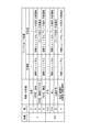
フェイルセーフ処置の詳細を図4に基づいて説明する。図4には示していないが、レンジ不一致異常と判定された場合、運転者の在席状況およびレンジによらず、フェイルセーフ処置として、モータリレー42をオフにしてモータ10の駆動を停止する。また、車内警告部81にて、車内に対してシフトバイワイヤシステム2の異常を通知する。
The details of the fail safe procedure will be described based on FIG. Although not shown in FIG. 4, when it is determined that the range mismatch abnormality is present, the drive of the motor 10 is stopped by turning off the motor relay 42 as a fail safe treatment regardless of the presence condition and the range of the driver. Further, the in-vehicle warning unit 81 notifies the in-vehicle of the abnormality of the shift by wire system 2.
目標レンジがPレンジ、実レンジがPレンジのとき、目標レンジと実レンジとが一致しており正常であるので、フェイルセーフ処置を行わない。同様に、目標レンジがRレンジ、実レンジがRレンジのとき、および、目標レンジがDレンジ、実レンジがDレンジのとき、目標レンジと実レンジとが一致しており正常であるので、フェイルセーフ処置を行わない。
When the target range is the P range and the actual range is the P range, the target range and the actual range match and are normal, so fail-safe processing is not performed. Similarly, when the target range is the R range and the actual range is the R range, and when the target range is the D range and the actual range is the D range, the target range and the actual range match and are normal. Do not take safe action.
目標レンジがPレンジ、実レンジがRレンジのとき、パーキングロック機構30をロックすることができない異常であるP不可異常の状態となり、車両への影響として、車両が逆走する虞がある。また、目標レンジがPレンジ、実レンジがDレンジのとき、P不可異常の状態となり、車両への影響として、車両が暴走する虞がある。目標レンジがPレンジ、実レンジがRレンジまたはDレンジであって、運転者が在席している場合、ソレノイド制御部52は、ソレノイド6を制御し、自動変速機5を強制的にニュートラル状態にする。また、車内警告を行うことで、運転者にパーキングブレーキ操作を促す。
When the target range is the P range and the actual range is the R range, the parking lock mechanism 30 can not be locked, resulting in a P impossible abnormality, which may cause the vehicle to run backward as an influence on the vehicle. In addition, when the target range is the P range and the actual range is the D range, the P is not normal and the vehicle may run away as an influence on the vehicle. When the target range is the P range and the actual range is the R range or D range, and the driver is present, the solenoid control unit 52 controls the solenoid 6 to force the automatic transmission 5 into the neutral state. Make it In addition, by warning the interior of the vehicle, the driver is urged to operate the parking brake.
目標レンジがPレンジ、実レンジがNレンジのとき、P不可異常の状態であって、車両への影響として、坂道での車両ずり下がりが生じる虞がある。実レンジがNレンジであるので、強制ニュートラル処置は不要である。
When the target range is the P range and the actual range is the N range, it is a P-impaired state, and there is a risk that the vehicle may fall downhill on a slope as an influence on the vehicle. As the actual range is N range, no forced neutral action is necessary.
運転者が不在の場合、目標レンジがPレンジ、実レンジがRレンジまたはDレンジのとき、SBW-ECU50は、運転者在席時と同様の自動変速機5の強制ニュートラル処置に加え、BBW-ECU71に対し、BBW装置61によるブレーキ作動を指示する。また、報知指令部56は、車外報知部82に対し、シフトバイワイヤシステム2の異常の車外への通知を指示する。
When the driver is absent, and the target range is the P range and the actual range is the R range or D range, the SBW-ECU 50 adds the BBW- to the forced neutral measures of the automatic transmission 5 similar to the driver presence. The ECU 71 is instructed to operate the brake by the BBW device 61. Further, the notification command unit 56 instructs the outside notification unit 82 to notify the abnormality of the shift by wire system 2 to the outside of the vehicle.
また、運転者が不在であって、目標レンジがPレンジ、実レンジがNレンジのとき、SBW-ECU50は、BBW-ECU71に対し、BBW装置61によるブレーキ作動を指示する。また、報知指令部56は、車外報知部82に対し、シフトバイワイヤシステム2の異常の車外への通知を指示する。
Further, when the driver is absent and the target range is the P range and the actual range is the N range, the SBW-ECU 50 instructs the BBW-ECU 71 to operate the brake by the BBW device 61. Further, the notification command unit 56 instructs the outside notification unit 82 to notify the abnormality of the shift by wire system 2 to the outside of the vehicle.
目標レンジがRレンジ、実レンジがDレンジのとき、および、目標レンジがDレンジ、実レンジがRレンジのとき、車両への影響として、運転者が意図する方向と反対方向に車両が逆走する虞がある。目標レンジがRレンジ、実レンジがDレンジのとき、および、目標レンジがDレンジ、実レンジがRレンジであって、運転者が在席している場合、強制ニュートラル処置が行われる。
When the target range is R range and the actual range is D range, and when the target range is D range and the actual range is R range, the vehicle travels in the opposite direction to the direction intended by the driver as the influence on the vehicle. There is a risk of When the target range is the R range and the actual range is the D range, and when the target range is the D range and the actual range is the R range and the driver is present, forced neutral processing is performed.
目標レンジがRレンジまたはDレンジ、実レンジがNレンジのとき、車両への影響として、加速ができない状態となる虞がある。実レンジがNレンジであるので、強制ニュートラル処置は不要である。
When the target range is the R range or the D range, and the actual range is the N range, there is a possibility that the vehicle can not be accelerated as an influence on the vehicle. As the actual range is N range, no forced neutral action is necessary.
目標レンジがRレンジまたはDレンジ、実レンジがPレンジの場合、車両への影響として、高速走行時、パーキングロック機構30の円錐体32がはじかれることにより生じるラチェッティングの異音が発生する虞がある。また、パーキングロック機構30がロック可能である所定速度以下の極低速走行時、パーキングロック機構30がロックされることによる車両の急減速が生じる虞がある。目標レンジがRレンジまたはDレンジであって、実レンジがPレンジであって、運転者が在席している場合、強制ニュートラル処置を行う。
When the target range is the R range or D range and the actual range is the P range, ratchet noise generated by flipping the cone 32 of the parking lock mechanism 30 occurs at high speed as an influence on the vehicle There is a risk. In addition, when traveling at a very low speed equal to or lower than a predetermined speed at which the parking lock mechanism 30 can be locked, there is a possibility that rapid deceleration of the vehicle may occur because the parking lock mechanism 30 is locked. When the target range is the R range or the D range, the actual range is the P range, and the driver is present, forced neutral processing is performed.
運転者が不在の場合、目標レンジがRレンジであって、実レンジがDレンジまたはPレンジのとき、および、目標レンジがDレンジであって、実レンジがRレンジまたはPレンジのとき、運転者在席時と同様の自動変速機5の強制ニュートラル処置に加え、SBW-ECU50は、BBW-ECU71に対し、BBW装置61によるブレーキ作動を指示する。また、運転者が不在であって、目標レンジがRレンジまたはDレンジであって、実レンジがNレンジのとき、SBW-ECU50は、BBW-ECU71に対し、BBW装置61によるブレーキ作動を指示する。さらにまた、運転者不在にて、レンジ不一致異常が生じている場合、報知指令部56は、車外報知部82に対し、シフトバイワイヤシステム2の異常を車外への通知を指示する。なお、目標レンジがRレンジまたはDレンジであって、運転者不在時のBBW作動および車外への通知の少なくとも一方は、省略してもよい。
When the driver is absent, the target range is the R range and the actual range is the D range or P range, and when the target range is the D range and the actual range is the R range or P range, driving is performed. The SBW-ECU 50 instructs the BBW-ECU 71 to perform the brake operation by the BBW device 61, in addition to the forced neutral processing of the automatic transmission 5 similar to that when the user is present. When the driver is absent and the target range is the R range or the D range and the actual range is the N range, the SBW-ECU 50 instructs the BBW-ECU 71 to operate the brake by the BBW device 61. . Furthermore, when there is a range mismatch abnormality in the absence of the driver, the notification instruction unit 56 instructs the outside notification unit 82 to notify the outside of the vehicle of the abnormality of the shift by wire system 2. The target range is the R range or the D range, and at least one of the BBW operation in the absence of the driver and the notification to the outside of the vehicle may be omitted.
例えば自動駐車時等、運転者が不在の状態にて、シフトレンジをPレンジに切り替えることができないP不可異常が生じた場合、シフトバイワイヤシステム2のパーキングロック機構30にて車両を固定することができず、車両のずり下がり等が生じる虞がある。そこで本実施形態では、運転者不在の状態にて、P不可異常が生じた場合、SBW-ECU50の制動指令部55からの指令によりBBW装置61を作動させ、車両を固定する。すなわち本実施形態では、シフトバイワイヤシステム2と電動ブレーキシステム3とを協調させてフェイルセーフ処置を行っているといえる。これにより、運転者の不在時にシフトバイワイヤシステム2に異常が生じた場合であっても、駐車完了後の車両のずり下がり等の意図しない動作を防ぐことができる。
For example, when there is a P-impaired abnormality in which the shift range can not be switched to the P range while the driver is absent, such as during automatic parking, the vehicle may be fixed by the parking lock mechanism 30 of the shift by wire system 2 There is a possibility that the vehicle may slip down or the like. Therefore, in the present embodiment, when a P-impaired abnormality occurs in the driver absent state, the BBW device 61 is operated by a command from the braking command unit 55 of the SBW-ECU 50 to fix the vehicle. That is, in the present embodiment, it can be said that the fail-safe treatment is performed by coordinating the shift-by-wire system 2 and the electric brake system 3. As a result, even when an abnormality occurs in the shift by wire system 2 when the driver is absent, it is possible to prevent an unintended operation such as a slippage of the vehicle after the parking is completed.
ところで、自動駐車完了後、イグニッションスイッチ等である車両の始動スイッチがオフされると、ECU50、71、72、75は、シャットダウン処理等を実行した後にオフされる。ここで、シフトバイワイヤシステム2におけるP入れ完了前にBBW-ECU71およびEPB-ECU72がオフされると、ECU71、72のオフ後にP不可異常となった場合、電動ブレーキシステム3による車両固定を行うことができない。そこで本実施形態では、SBW-ECU50がオフされた後に、BBW-ECU71およびEPB-ECU72がオフされるようにしている。
By the way, when the start switch of the vehicle which is an ignition switch or the like is turned off after the automatic parking is completed, the ECUs 50, 71, 72, 75 are turned off after executing the shutdown processing or the like. Here, if the BBW-ECU 71 and the EPB-ECU 72 are turned off before P is completed in the shift-by-wire system 2, and if P becomes impossible after the ECUs 71 and 72 are turned off, the vehicle is fixed by the electric brake system 3. I can not Therefore, in the present embodiment, the BBW-ECU 71 and the EPB-ECU 72 are turned off after the SBW-ECU 50 is turned off.
SBW-ECU50における電源制御処理を図5のフローチャートに基づいて説明する。この処理は、SBW-ECU50にて所定の周期で実行される。S201では、SBW-ECU50は、IGがオフされたか否かを判断する。IGがオフされていないと判断された場合(S201:NO)、S202へ移行し、シフトバイワイヤシステム2のオン状態を継続する。また、S203では、SBW-ECU50は、自動駐車用ECU75やシフターからの指令等に応じたレンジ切替制御を行う。IGがオフされたと判断された場合(S201:YES)、S204へ移行する。
The power control process in the SBW-ECU 50 will be described based on the flowchart of FIG. This process is executed by SBW-ECU 50 at a predetermined cycle. In S201, the SBW-ECU 50 determines whether the IG is turned off. If it is determined that the IG is not turned off (S201: NO), the process proceeds to S202, and the on state of the shift by wire system 2 is continued. In S203, the SBW-ECU 50 performs range switching control in accordance with an instruction from the automatic parking ECU 75 or the shifter. If it is determined that the IG is turned off (S201: YES), the process proceeds to S204.
S204では、SBW-ECU50は、実レンジがPレンジか否かを判断する。実レンジがPレンジであると判断された場合(S204:YES)、S205へ移行し、P作動が完了した旨の情報を、ブレーキ制御装置70に通知する。ブレーキ制御装置70への通知は、BBW-ECU71およびEPB-ECU72の少なくとも一方に対して行われる。P作動が完了していないと判断された場合(S204:NO)、S206へ移行し、駆動制御部51は実レンジがPレンジとなるように、モータ10を制御する。
In S204, the SBW-ECU 50 determines whether the actual range is the P range. If it is determined that the actual range is the P range (S204: YES), the process proceeds to S205, and the brake control device 70 is notified of information that P operation has been completed. The notification to the brake control device 70 is performed to at least one of the BBW-ECU 71 and the EPB-ECU 72. When it is determined that the P operation is not completed (S204: NO), the process proceeds to S206, and the drive control unit 51 controls the motor 10 so that the actual range becomes the P range.
S207では、異常監視部53は、P作動指令後、判定時間Xthが経過したか否かを判断する。判定時間Xthが経過していないと判断された場合(S207:NO)、S204へ戻る。判定時間Xthが経過したと判断された場合(S207:YES)、S208へ移行し、P不可異常が生じていると判定され、図4にて説明したP不可異常時のフェイルセーフ処置が実行される。
In S207, the abnormality monitoring unit 53 determines whether the determination time Xth has elapsed after the P operation command. If it is determined that the determination time Xth has not elapsed (S207: NO), the process returns to S204. If it is determined that the determination time Xth has elapsed (S207: YES), the process proceeds to S208, in which it is determined that a P-impaired abnormality has occurred, and the failsafe procedure for P-impairment abnormality described in FIG. Ru.
S205またはS208に続いて移行するS209では、SBW-ECU50は、モータ10をオフにし、シャットダウン処理後、SBW-ECU50をオフにする。
In S209, which follows S205 or S208, the SBW-ECU 50 turns off the motor 10, and after shutdown processing, turns off the SBW-ECU 50.
ブレーキ制御装置70における電源制御処理を図6のフローチャートに基づいて説明する。この処理は、ブレーキ制御装置70にて所定の周期で実行される。動作主体をブレーキ制御装置70として記載している処理は、BBW-ECU71およびEPB-ECU72の少なくとも一方で実行されるものとする。
The power control process in the brake control device 70 will be described based on the flowchart of FIG. This process is executed by the brake control device 70 at a predetermined cycle. The processing in which the action subject is described as the brake control device 70 is executed by at least one of the BBW-ECU 71 and the EPB-ECU 72.
S301では、ブレーキ制御装置70は、IGがオフされたか否かを判断する。IGがオフされていないと判断された場合(S301:NO)、S302へ移行し、ブレーキバイワイヤシステムおよび電動パーキングブレーキシステムのオン状態を継続する。S303では、ブレーキ制御装置70は、ブレーキペダルの踏込量や自動駐車用ECU75からの指令等に応じ、ブレーキ制御を行う。
In S301, the brake control device 70 determines whether or not the IG is turned off. If it is determined that the IG is not turned off (S301: NO), the process proceeds to S302, and the on state of the brake-by-wire system and the electric parking brake system is continued. In S303, the brake control device 70 performs the brake control according to the depression amount of the brake pedal, the command from the ECU 75 for automatic parking, and the like.
S304では、ブレーキ制御装置70は、シフトバイワイヤシステム2にてP作動が完了したか否かを判断する。P作動の完了は、SBW-ECU50から送信されるP作動完了通知に基づいて判定される。P作動が完了したと判断された場合(S304:YES)、S306へ移行する。P作動が完了していないと判断された場合(S304:NO)、S305へ移行する。
In S304, the brake control device 70 determines whether P operation has been completed in the shift by wire system 2. The completion of the P operation is determined based on the P operation completion notification transmitted from the SBW-ECU 50. If it is determined that the P operation has been completed (S304: YES), the process proceeds to S306. If it is determined that the P operation is not completed (S304: NO), the process proceeds to S305.
S305では、ブレーキ制御装置70は、P作動指令後、判定時間Xthが経過したか否かを判断する。ここでは、ブレーキ制御装置70側にて計時して判定を行ってもよいし、SBW-ECU50からP不可異常が生じている旨の情報を受信したとき、判定時間Xthが経過したと判断してもよい。判定時間Xthが経過していないと判断された場合(S305:NO)、S306~S308の処理を行わず、電動ブレーキシステム3のオン状態を継続する。判定時間Xthが経過したと判断された場合(S305:YES)、S306へ移行する。
In S305, the brake control device 70 determines whether the determination time Xth has elapsed after the P actuation command. Here, the determination may be made by counting on the brake control device 70 side, or when information indicating that a P impossible abnormality has occurred is received from the SBW-ECU 50, it is determined that the determination time Xth has elapsed. It is also good. If it is determined that the determination time Xth has not elapsed (S305: NO), the processing of S306 to S308 is not performed, and the on state of the electric brake system 3 is continued. If it is determined that the determination time Xth has elapsed (S305: YES), the process proceeds to S306.
S306では、EPB-ECU72は、EPBアクチュエータ66を駆動し、EPB装置62を作動させる。EPB装置62の作動完了後、EPBアクチュエータ66をオフにする。
In S306, the EPB-ECU 72 drives the EPB actuator 66 to operate the EPB device 62. After the operation of the EPB device 62 is completed, the EPB actuator 66 is turned off.
S307では、EPB-ECU72は、シャットダウン処理後、EPB-ECU72をオフにする。上述の通り、EPB装置62を作動させた場合、制動解除処理が行われるまで、オフ後の制動状態が継続される。
In S307, the EPB-ECU 72 turns off the EPB-ECU 72 after the shutdown process. As described above, when the EPB device 62 is operated, the braking state after the off is continued until the braking release process is performed.
S308では、BBW-ECU71は、BBWアクチュエータ65をオフにし、シャットダウン処理後、BBW-ECU71をオフにする。
In S308, the BBW-ECU 71 turns off the BBW actuator 65, and turns off the BBW-ECU 71 after the shutdown process.
本実施形態の電源制御処理を図7のタイムチャートに基づいて説明する。図7は、共通時間軸を横軸とし、上段から、車速、IGのオンオフ状態、自動駐車制御のオンオフ状態、SBW制御、SBW-ECU50のオンオフ状態、BBW-ECU71のオンオフ状態、EPB-ECU72のオンオフ状態、ならびに、EPB制御を示している。図7では、時刻x11まではシフトバイワイヤシステム2は正常に動作しており、時刻x11にてシフトレンジをPレンジに切り替える際に、P不可異常が検出されたものとする。なお、説明のため、タイムスケールは適宜変更しており、実際とは必ずしも一致しない。また、ECU50、71、72のオフタイミングについては、シャットダウン処理に要する時間を省略した。
The power control process of the present embodiment will be described based on the time chart of FIG. In FIG. 7, the horizontal axis represents the common time axis, and from the top, vehicle speed, IG on / off state, automatic parking control on / off state, SBW control, SBW-ECU 50 on / off state, BBW-ECU 71 on / off state, EPB-ECU 72 On and off states as well as EPB control are shown. In FIG. 7, it is assumed that the shift-by-wire system 2 operates normally until time x11, and a P impossible abnormality is detected when switching the shift range to the P range at time x11. Note that the time scale is appropriately changed for the sake of explanation, and does not necessarily coincide with the actual. Moreover, about the OFF timing of ECU50, 71, 72, the time which a shutdown process requires was abbreviate | omitted.
時刻x10にて、運転者から指令により、自動駐車制御が実行される。自動駐車制御中は、シフトレンジの切り替えを繰り返し、所望の箇所に車両を駐車させる。図7では、R→D→Rとレンジが切り替えられるが、切り返しの回数や各レンジの継続時間等は問わない。
Automatic parking control is executed at time x10 according to a command from the driver. During automatic parking control, switching of the shift range is repeated to park the vehicle at a desired location. In FIG. 7, the range is switched from R to D to R, but the number of times of turning back, the duration of each range, and the like do not matter.
時刻x11にて、自動駐車制御が完了し、IGがオフされると、一点鎖線で示すように、目標シフトレンジがPレンジに切り替わる。シフトバイワイヤシステム2が正常の場合、破線で示すように、判定時間Xthが経過するより前のタイミングにて、Pレンジに切り替わる。図7では、IGオフ、自動駐車制御オフ、および、Pレンジへの切替指令が同時に行われるように記載されているが、例えば自動駐車用ECU75からPレンジへの切り替えが指令され、その後にIGがオフされるようにしてもよいし、IGオフをトリガとしてPレンジへの切り替えが指令されるようにしてもよく、制御順は問わない。
At time x11, when the automatic parking control is completed and the IG is turned off, the target shift range is switched to the P range as indicated by the one-dot chain line. When the shift-by-wire system 2 is normal, as indicated by a broken line, switching to the P range is performed at a timing before the determination time Xth elapses. In FIG. 7, it is described that IG OFF, automatic parking control OFF, and switching instruction to P range are simultaneously performed, but for example, ECU 75 for automatic parking instructs switching to P range, and then IG May be turned off, or switching to the P range may be commanded using IG off as a trigger, and the control order does not matter.
時刻x11にてPレンジへの切り替えが指令されたにも関わらず、シフトレンジがPレンジに切り替わらないP不可異常が発生した場合、時刻x11から判定時間Xthが経過した時刻x12にて、EPB装置62を作動させる。また、EPB装置62の作動完了後の時刻x13にて、EPB制御を終了するとともに、シャットダウン処理後、EPB-ECU72をオフにする。また、EPB-ECU72をオフした後の時刻x14にて、BBW-ECU71をオフにする。図7では、P不可異常時について説明しているが、レンジ不一致異常の有無によらず、本実施形態では、SBW-ECU50、EPB-ECU72、BBW-ECU71の順に電源がオフされる。
If a P-impossible abnormality in which the shift range does not switch to the P range occurs despite the command to switch to the P range at time x11, the EPB apparatus at time x12 when the determination time Xth has elapsed from time x11 Activate 62. Further, at time x13 after the completion of the operation of the EPB device 62, the EPB control is ended, and after the shutdown processing, the EPB-ECU 72 is turned off. Also, at time x14 after the EPB-ECU 72 is turned off, the BBW-ECU 71 is turned off. Although FIG. 7 describes the P-impossible abnormality, the power is turned off in the order of SBW-ECU 50, EPB-ECU 72, and BBW-ECU 71 in this embodiment regardless of the presence or absence of range mismatch abnormality.
図7では、BBW制御の記載を省略したが、自動駐車用EUC75からの指令等に応じて制御される。BBW制御終了タイミングは、EPB制御終了の時刻x13と同時でもよいし、時刻x13以降であってBBW-ECU71がオフされる時刻x14以前のいずれのタイミングとしてもよい。
Although the description of the BBW control is omitted in FIG. 7, control is performed according to a command from the EUC 75 for automatic parking. The BBW control end timing may be simultaneous with the time x13 when the EPB control ends, or may be any time after the time x13 and before the time x14 when the BBW-ECU 71 is turned off.
以上説明したように、本実施形態の車両用制御装置100は、シフトバイワイヤシステム2、および、電動ブレーキシステム3を含む車両制御システム1を制御する。シフトバイワイヤシステム2は、モータ10の駆動を制御することでシフトレンジを切り替える。電動ブレーキシステム3は、BBWアクチュエータ65およびEPBアクチュエータ66の駆動を制御することで車両を制動させる。
As described above, the vehicle control device 100 of the present embodiment controls the vehicle control system 1 including the shift by wire system 2 and the electric brake system 3. The shift by wire system 2 switches the shift range by controlling the drive of the motor 10. The electric brake system 3 brakes the vehicle by controlling the driving of the BBW actuator 65 and the EPB actuator 66.
車両用制御装置100は、シフト制御部およびブレーキ制御部を備える。本実施形態では、シフト制御部であるSBW-ECU50は、モータ10の駆動を制御する。ブレーキ制御部であるBBW-ECU71は、ブレーキアクチュエータであるBBWアクチュエータ65の駆動を制御する。ブレーキ制御部であるEPB-ECU72は、ブレーキアクチュエータであるEPBアクチュエータ66の駆動を制御する。車両の始動スイッチがオフされた場合、シフトバイワイヤシステム2のPレンジへの切替完了後、BBW-ECU71およびEPB-ECU72の電源をオフにする。
The vehicle control device 100 includes a shift control unit and a brake control unit. In the present embodiment, the SBW-ECU 50, which is a shift control unit, controls the drive of the motor 10. The BBW-ECU 71, which is a brake control unit, controls the drive of the BBW actuator 65, which is a brake actuator. The EPB-ECU 72, which is a brake control unit, controls the drive of the EPB actuator 66, which is a brake actuator. When the start switch of the vehicle is turned off, the power of the BBW-ECU 71 and the EPB-ECU 72 is turned off after the shift to the P range of the shift by wire system 2 is completed.
例えば自動駐車の完了後に、P不可異常が生じると、シフトバイワイヤシステム2にて車両を固定することができず、車両のずり下がり等が発生する虞がある。そこで本実施形態では、シフトバイワイヤシステム2のPレンジへの切り替え後に、BBW-ECU71およびEPB-ECU72の電源をオフにするようにしている。換言すると、シフトバイワイヤシステム2のP入れ完了までは、BBW-ECU71およびEPB-ECU72をオフにしない。これにより、P不可異常が発生した場合、電動ブレーキシステム3による車両固定を確実に行うことができるので、シフトバイワイヤシステム2に異常が生じた場合の安全性を向上可能である。
For example, if the P-impaired abnormality occurs after completion of the automatic parking, the vehicle can not be fixed by the shift-by-wire system 2, and the vehicle may be slipped down. Therefore, in the present embodiment, the power of the BBW-ECU 71 and the EPB-ECU 72 is turned off after the shift-by-wire system 2 is switched to the P range. In other words, the BBW-ECU 71 and the EPB-ECU 72 are not turned off until the P insertion of the shift by wire system 2 is completed. As a result, when a P-impaired abnormality occurs, the vehicle can be fixed securely by the electric brake system 3, so that the safety in the case where an abnormality occurs in the shift-by-wire system 2 can be improved.
SBW-ECU50の電源がオフされた後、BBW-ECU71およびEPB-ECU72の電源がオフされる。本実施形態では、SBW-ECU50、EPB-ECU72、BBW-ECU71の順に電源がオフされる。これにより、P不可異常が発生した場合であっても、確実に車両固定を行うことができる。
After the power of SBW-ECU 50 is turned off, the powers of BBW-ECU 71 and EPB-ECU 72 are turned off. In the present embodiment, the power is turned off in order of the SBW-ECU 50, the EPB-ECU 72, and the BBW-ECU 71. As a result, even when the P impossibility has occurred, the vehicle can be fixed securely.
電動ブレーキシステム3は、通電オフ後も制動状態を維持可能なEPB装置62を有する。シフトバイワイヤシステム2にてPレンジへの切り替えが不能となるP不可異常が生じた場合、EPB装置62を作動させた後、BBW-ECU71およびEPB-ECU72の電源をオフにする。これにより、P不可異常が発生した場合であっても、確実に車両固定を行うことができる。
The electric brake system 3 has an EPB device 62 capable of maintaining the braking state even after the power-off. When a P-impaired abnormality that makes it impossible to switch to the P range in the shift-by-wire system 2 occurs, the EPB device 62 is operated, and then the power of the BBW-ECU 71 and the EPB-ECU 72 is turned off. As a result, even when the P impossibility has occurred, the vehicle can be fixed securely.
(他の実施形態)
上記実施形態では、レンジ不一致異常が生じた場合、BBW装置61を作動させて車両を固定する。他の実施形態では、レンジ不一致異常が生じた場合、BBW装置61に加え、EPB装置62を作動させてもよい。また、BBW装置61に替えて、EPB装置62を作動させてもよい。上記実施形態では、電動ブレーキシステムには、BBWシステムおよびEPBシステムが含まれるが、いずれか一方がメカ式のものであってもよい。また、電動ブレーキシステムはブレーキ制御装置により制動を制御可能であれば、上記実施形態の構成に限らず、どのような構成であってもよい。 (Other embodiments)
In the above embodiment, when a range mismatch abnormality occurs, theBBW device 61 is operated to fix the vehicle. In another embodiment, in addition to the BBW device 61, the EPB device 62 may be activated when a range mismatch abnormality occurs. Also, instead of the BBW device 61, the EPB device 62 may be operated. In the above embodiment, the electric brake system includes the BBW system and the EPB system, but either one may be mechanical. Further, the electric brake system is not limited to the configuration of the above embodiment as long as the brake control device can control the braking, and any configuration may be used.
上記実施形態では、レンジ不一致異常が生じた場合、BBW装置61を作動させて車両を固定する。他の実施形態では、レンジ不一致異常が生じた場合、BBW装置61に加え、EPB装置62を作動させてもよい。また、BBW装置61に替えて、EPB装置62を作動させてもよい。上記実施形態では、電動ブレーキシステムには、BBWシステムおよびEPBシステムが含まれるが、いずれか一方がメカ式のものであってもよい。また、電動ブレーキシステムはブレーキ制御装置により制動を制御可能であれば、上記実施形態の構成に限らず、どのような構成であってもよい。 (Other embodiments)
In the above embodiment, when a range mismatch abnormality occurs, the
上記実施形態では、IGがオフされたときにシフト切替システムが正常であれば、SBW-ECU50の電源オフ、EPB-ECU72の電源オフ、BBW-ECU71の電源オフの順で行われる。また、IGがオフされたときにP不可異常が生じた場合、SBW-ECU50の電源オフ、EPB装置作動、EPB-ECU72の電源オフ、BBW-ECU71の電源オフの順で行われる。他の実施形態では、シフトバイワイヤシステムにおけるPレンジへの切替完了、または、電動ブレーキシステムによる車両固定完了後にブレーキ制御部の電源がオフにされるように構成されていればよく、上記の制御順は異なっていてもよい。また、電動ブレーキシステムとしてEPB装置を有していない場合、BBW-ECUの電源をオフにせず、BBW装置の作動を継続するようにしてもよい。
In the above embodiment, if the shift switching system is normal when the IG is turned off, the power is turned off in the SBW-ECU 50, the power in the EPB-ECU 72 is turned off, and the power in the BBW-ECU 71 is turned off. Further, when a P failure abnormality occurs when the IG is turned off, the power is turned off in the SBW-ECU 50, the EPB device is activated, the power in the EPB-ECU 72 is turned off, and the power in the BBW-ECU 71 is turned off. In another embodiment, the power of the brake control unit may be turned off after completion of switching to the P range in the shift-by-wire system or completion of vehicle fixation by the electric brake system, and the control sequence described above may be performed. May be different. Further, when the EPB device is not provided as the electric brake system, the BBW-ECU may be continued to operate without powering off the BBW-ECU.
上記実施形態では、SBW-ECU、BBW-ECUおよびEPB-ECUが別途のECUとして設けられている。他の実施形態では、これらの少なくとも一部が1つのECUとして設けられていてもよい。この場合、各種情報の授受は、車両通信網を介さず、内部的に行われるようにすればよい。
In the above embodiment, the SBW-ECU, the BBW-ECU, and the EPB-ECU are provided as separate ECUs. In another embodiment, at least a part of these may be provided as one ECU. In this case, transmission and reception of various information may be performed internally without passing through the vehicle communication network.
上記実施形態では、モータ回転角センサは、エンコーダである。他の実施形態では、モータ回転角センサは、エンコーダに限らず、レゾルバ等、どのようなものを用いてもよい。上記実施形態では、出力軸センサとしてポテンショメータを例示した。他の実施形態では、出力軸センサは、どのようなものであってもよく、例えば、各レンジ保証領域にてオンされるスイッチにより構成されてもよいし、非接触の磁気センサを用いてもよい。また、出力軸センサを省略してもよい。
In the above embodiment, the motor rotation angle sensor is an encoder. In another embodiment, the motor rotation angle sensor is not limited to the encoder, and any sensor such as a resolver may be used. In the above embodiment, a potentiometer is illustrated as an output axis sensor. In other embodiments, the output shaft sensor may be of any type, for example, may be constituted by a switch turned on in each range guaranteeing area, or a non-contact magnetic sensor may be used. Good. Also, the output shaft sensor may be omitted.
上記実施形態では、ディテントプレートには4つの谷部が設けられる。他の実施形態では、谷部の数は4つに限らず、いくつであってもよい。例えば、Pレンジと、Pレンジ以外のレンジであるnotPレンジに対応する2つの谷部が設けられていてもよい。シフトレンジ切替機構やパーキングロック機構等は、上記実施形態と異なっていてもよい。
In the above embodiment, the detent plate is provided with four valleys. In other embodiments, the number of valleys is not limited to four, but may be any number. For example, two valleys corresponding to the P range and the not P range which is a range other than the P range may be provided. The shift range switching mechanism, the parking lock mechanism, etc. may be different from the above embodiment.
上記実施形態では、モータ軸と出力軸との間に減速機が設けられる。減速機の詳細について、上記実施形態では言及していないが、例えば、サイクロイド歯車、遊星歯車、モータ軸と略同軸の減速機構から駆動軸へトルクを伝達する平歯歯車を用いたものや、これらを組み合わせて用いたもの等、どのような構成であってもよい。また、他の実施形態では、モータ軸と出力軸との間の減速機を省略してもよいし、減速機以外の機構を設けてもよい。以上、本開示は、上記実施形態になんら限定されるものではなく、その趣旨を逸脱しない範囲において種々の形態で実施可能である。
In the above embodiment, a reduction gear is provided between the motor shaft and the output shaft. Although the details of the reduction gear are not mentioned in the above embodiment, for example, a cycloid gear, a planetary gear, a spur gear that transmits torque from the reduction mechanism substantially coaxial with the motor shaft to the drive shaft, or these Any configuration may be used, such as one using a combination of In other embodiments, the reduction gear between the motor shaft and the output shaft may be omitted, or a mechanism other than the reduction gear may be provided. As mentioned above, this indication is not limited at all to the above-mentioned embodiment, and can be carried out in various forms in the range which does not deviate from the meaning.
本開示は、実施形態に準拠して記述された。しかしながら、本開示は当該実施形態および構造に限定されるものではない。本開示は、様々な変形例および均等の範囲内の変形をも包含する。また、様々な組み合わせおよび形態、さらには、それらに一要素のみ、それ以上、あるいはそれ以下、を含む他の組み合わせおよび形態も、本開示の範疇および思想範囲に入るものである。
The present disclosure has been described in accordance with the embodiments. However, the present disclosure is not limited to the embodiments and structures. The present disclosure also includes various modifications and variations within the scope of equivalents. In addition, various combinations and forms, and further, other combinations and forms including one element or more, or less or less, are also within the scope and the scope of the present disclosure.
Claims (3)
- シフトアクチュエータ(10)の駆動を制御することでシフトレンジを切り替えるシフトレンジ切替システム(2)、および、ブレーキアクチュエータ(65、66)の駆動を制御することで車両を制動させる電動ブレーキシステム(3)を含む車両制御システム(1)を制御する車両用制御装置であって、
前記シフトアクチュエータの駆動を制御するシフト制御部(50)と、
前記ブレーキアクチュエータの駆動を制御するブレーキ制御部(71、72)と、
を備え、
車両の始動スイッチがオフされた場合、前記シフトレンジ切替システムのPレンジへの切替完了後、前記ブレーキ制御部の電源をオフにする車両用制御装置。 A shift range switching system (2) for switching the shift range by controlling the drive of the shift actuator (10), and an electric brake system (3) for braking the vehicle by controlling the drive of the brake actuator (65, 66) Control device for controlling a vehicle control system (1) including
A shift control unit (50) that controls driving of the shift actuator;
A brake control unit (71, 72) for controlling the drive of the brake actuator;
Equipped with
The control apparatus for vehicles which turns off the power supply of the said brake control part after completion | finish of switching to the P range of the said shift range switching system when the start switch of a vehicle is turned off. - 前記シフト制御部の電源がオフされた後、前記ブレーキ制御部の電源がオフされる請求項1に記載の車両用制御装置。 The vehicle control device according to claim 1, wherein the power supply of the brake control unit is turned off after the power supply of the shift control unit is turned off.
- 前記電動ブレーキシステムは、通電オフ後も制動状態を維持可能な電動パーキングブレーキ装置(62)を有し、
前記シフトレンジ切替システムにてPレンジへの切り替えが不能となるP不可異常が生じた場合、前記電動パーキングブレーキ装置を作動させた後、前記ブレーキ制御部の電源をオフにする請求項1または2に記載の車両用制御装置。 The electric brake system includes an electric parking brake device (62) capable of maintaining a braking state even after the power is off,
The power control of the brake control unit is turned off after the electric parking brake device is operated when a P-impaired abnormality that makes it impossible to switch to the P range occurs in the shift range switching system. The vehicle control device according to.
Priority Applications (3)
| Application Number | Priority Date | Filing Date | Title |
|---|---|---|---|
| CN201880072299.8A CN111344201B (en) | 2017-11-24 | 2018-11-16 | Vehicle control device |
| DE112018006012.8T DE112018006012T5 (en) | 2017-11-24 | 2018-11-16 | Vehicle control device |
| US16/871,372 US11112008B2 (en) | 2017-11-24 | 2020-05-11 | Vehicle control device |
Applications Claiming Priority (2)
| Application Number | Priority Date | Filing Date | Title |
|---|---|---|---|
| JP2017-226017 | 2017-11-24 | ||
| JP2017226017A JP6881253B2 (en) | 2017-11-24 | 2017-11-24 | Vehicle control device |
Related Child Applications (1)
| Application Number | Title | Priority Date | Filing Date |
|---|---|---|---|
| US16/871,372 Continuation US11112008B2 (en) | 2017-11-24 | 2020-05-11 | Vehicle control device |
Publications (1)
| Publication Number | Publication Date |
|---|---|
| WO2019102934A1 true WO2019102934A1 (en) | 2019-05-31 |
Family
ID=66631857
Family Applications (1)
| Application Number | Title | Priority Date | Filing Date |
|---|---|---|---|
| PCT/JP2018/042402 WO2019102934A1 (en) | 2017-11-24 | 2018-11-16 | Vehicle control device |
Country Status (5)
| Country | Link |
|---|---|
| US (1) | US11112008B2 (en) |
| JP (1) | JP6881253B2 (en) |
| CN (1) | CN111344201B (en) |
| DE (1) | DE112018006012T5 (en) |
| WO (1) | WO2019102934A1 (en) |
Cited By (2)
| Publication number | Priority date | Publication date | Assignee | Title |
|---|---|---|---|---|
| US10844954B2 (en) | 2017-11-20 | 2020-11-24 | Denso Corporation | Shift range control device |
| US11092236B2 (en) | 2017-11-24 | 2021-08-17 | Denso Corporation | Vehicle control device |
Families Citing this family (2)
| Publication number | Priority date | Publication date | Assignee | Title |
|---|---|---|---|---|
| JP2022144098A (en) * | 2021-03-18 | 2022-10-03 | 本田技研工業株式会社 | Vehicle control device |
| JP7414037B2 (en) * | 2021-04-28 | 2024-01-16 | 株式会社デンソー | Vehicle control device |
Citations (4)
| Publication number | Priority date | Publication date | Assignee | Title |
|---|---|---|---|---|
| JP2007284036A (en) * | 2006-03-23 | 2007-11-01 | Aisin Aw Co Ltd | Parking control system for vehicle |
| JP2008213683A (en) * | 2007-03-05 | 2008-09-18 | Toyota Motor Corp | Vehicle parking system |
| JP2011074981A (en) * | 2009-09-30 | 2011-04-14 | Jatco Ltd | Control device of shift-by-wire type vehicle |
| JP2013199165A (en) * | 2012-03-23 | 2013-10-03 | Fuji Heavy Ind Ltd | Fail-safe device for shift-by-wire system |
Family Cites Families (14)
| Publication number | Priority date | Publication date | Assignee | Title |
|---|---|---|---|---|
| JP2005180653A (en) | 2003-12-22 | 2005-07-07 | Denso Corp | Abnormality diagnostic device of motor driving system |
| JP4367620B2 (en) | 2003-12-22 | 2009-11-18 | 株式会社デンソー | Abnormality diagnosis device for motor drive system |
| US7731627B2 (en) * | 2006-03-23 | 2010-06-08 | Aisin Aw Co., Ltd. | Vehicle parking control system |
| DE102007042210B4 (en) * | 2007-09-05 | 2011-07-07 | ZF Friedrichshafen AG, 88046 | Method for automatically inserting a parking brake of an automatic or automated transmission of a motor vehicle |
| JP4525738B2 (en) * | 2007-11-13 | 2010-08-18 | 株式会社デンソー | Shift range switching device |
| JP5177043B2 (en) * | 2009-03-25 | 2013-04-03 | トヨタ自動車株式会社 | Vehicle control apparatus and control method |
| JP4894933B2 (en) * | 2009-06-04 | 2012-03-14 | 株式会社デンソー | Shift range switching device and parking lock device |
| JP5327149B2 (en) * | 2010-02-10 | 2013-10-30 | 株式会社デンソー | In-vehicle communication device |
| JP6492778B2 (en) | 2015-03-05 | 2019-04-03 | 株式会社デンソー | Range switching control device |
| CN106032141B (en) * | 2015-03-19 | 2019-01-29 | 比亚迪股份有限公司 | Parking braking control system, method and vehicle for vehicle |
| CN107097783A (en) * | 2017-04-10 | 2017-08-29 | 广州汽车集团股份有限公司 | P keeps off parking control method and system and the vehicle with the system |
| JP7009936B2 (en) | 2017-11-06 | 2022-01-26 | 株式会社デンソー | Shift range controller |
| JP6863245B2 (en) | 2017-11-20 | 2021-04-21 | 株式会社デンソー | Shift range controller |
| JP6852658B2 (en) | 2017-11-24 | 2021-03-31 | 株式会社デンソー | Vehicle control device |
-
2017
- 2017-11-24 JP JP2017226017A patent/JP6881253B2/en active Active
-
2018
- 2018-11-16 CN CN201880072299.8A patent/CN111344201B/en active Active
- 2018-11-16 WO PCT/JP2018/042402 patent/WO2019102934A1/en active Application Filing
- 2018-11-16 DE DE112018006012.8T patent/DE112018006012T5/en active Pending
-
2020
- 2020-05-11 US US16/871,372 patent/US11112008B2/en active Active
Patent Citations (4)
| Publication number | Priority date | Publication date | Assignee | Title |
|---|---|---|---|---|
| JP2007284036A (en) * | 2006-03-23 | 2007-11-01 | Aisin Aw Co Ltd | Parking control system for vehicle |
| JP2008213683A (en) * | 2007-03-05 | 2008-09-18 | Toyota Motor Corp | Vehicle parking system |
| JP2011074981A (en) * | 2009-09-30 | 2011-04-14 | Jatco Ltd | Control device of shift-by-wire type vehicle |
| JP2013199165A (en) * | 2012-03-23 | 2013-10-03 | Fuji Heavy Ind Ltd | Fail-safe device for shift-by-wire system |
Cited By (2)
| Publication number | Priority date | Publication date | Assignee | Title |
|---|---|---|---|---|
| US10844954B2 (en) | 2017-11-20 | 2020-11-24 | Denso Corporation | Shift range control device |
| US11092236B2 (en) | 2017-11-24 | 2021-08-17 | Denso Corporation | Vehicle control device |
Also Published As
| Publication number | Publication date |
|---|---|
| US11112008B2 (en) | 2021-09-07 |
| DE112018006012T5 (en) | 2020-08-20 |
| CN111344201B (en) | 2022-04-26 |
| CN111344201A (en) | 2020-06-26 |
| US20200271224A1 (en) | 2020-08-27 |
| JP6881253B2 (en) | 2021-06-02 |
| JP2019093962A (en) | 2019-06-20 |
Similar Documents
| Publication | Publication Date | Title |
|---|---|---|
| US11092236B2 (en) | Vehicle control device | |
| WO2019102934A1 (en) | Vehicle control device | |
| JP4833097B2 (en) | Shift-by-wire device | |
| US9233666B2 (en) | Shift-by-wire vehicle and method to verify securement | |
| EP1845495B1 (en) | Electric Parking Brake System | |
| JP4535174B2 (en) | Vehicle control apparatus and control method | |
| US20090287383A1 (en) | Shift-by-wire control system for vehicle automatic transmission | |
| JP2013199165A (en) | Fail-safe device for shift-by-wire system | |
| WO2016139904A1 (en) | Range-switching control device | |
| US9086949B2 (en) | Control device for vehicle | |
| JP3956962B2 (en) | Parking lock device | |
| WO2018221239A1 (en) | Shift range control apparatus | |
| JP2007032819A (en) | Vehicle control system | |
| JP5846394B2 (en) | Actuator control device | |
| JP6214512B2 (en) | Parking lock mechanism | |
| JP6992310B2 (en) | Shift-by-wire controller | |
| JP7373439B2 (en) | Shift operation determination device and shift device | |
| JP7176370B2 (en) | vehicle controller | |
| WO2015141043A1 (en) | Parking lock mechanism control device and control method | |
| JP2012106539A (en) | Shift-by-wire | |
| KR20160107955A (en) | control apparatus of acceleration | |
| JP2023032422A (en) | Control device for parking lock | |
| JP2004314861A (en) | Driving mode changeover control device of transfer | |
| KR20160034438A (en) | Method and appratus for controlling parking pawl |
Legal Events
| Date | Code | Title | Description |
|---|---|---|---|
| 121 | Ep: the epo has been informed by wipo that ep was designated in this application |
Ref document number: 18881206 Country of ref document: EP Kind code of ref document: A1 |
|
| 122 | Ep: pct application non-entry in european phase |
Ref document number: 18881206 Country of ref document: EP Kind code of ref document: A1 |