JP6881253B2 - Vehicle control device - Google Patents
Vehicle control device Download PDFInfo
- Publication number
- JP6881253B2 JP6881253B2 JP2017226017A JP2017226017A JP6881253B2 JP 6881253 B2 JP6881253 B2 JP 6881253B2 JP 2017226017 A JP2017226017 A JP 2017226017A JP 2017226017 A JP2017226017 A JP 2017226017A JP 6881253 B2 JP6881253 B2 JP 6881253B2
- Authority
- JP
- Japan
- Prior art keywords
- range
- shift
- ecu
- vehicle
- brake
- Prior art date
- Legal status (The legal status is an assumption and is not a legal conclusion. Google has not performed a legal analysis and makes no representation as to the accuracy of the status listed.)
- Active
Links
- 230000005856 abnormality Effects 0.000 claims description 53
- 238000000034 method Methods 0.000 description 32
- 230000008569 process Effects 0.000 description 29
- 230000007246 mechanism Effects 0.000 description 21
- 230000001276 controlling effect Effects 0.000 description 13
- 230000007935 neutral effect Effects 0.000 description 8
- 239000003638 chemical reducing agent Substances 0.000 description 7
- 238000012544 monitoring process Methods 0.000 description 6
- 238000004891 communication Methods 0.000 description 5
- 230000000694 effects Effects 0.000 description 5
- 230000005540 biological transmission Effects 0.000 description 4
- 230000004044 response Effects 0.000 description 4
- 230000002159 abnormal effect Effects 0.000 description 3
- 238000001514 detection method Methods 0.000 description 3
- 238000012545 processing Methods 0.000 description 3
- 238000003780 insertion Methods 0.000 description 2
- 230000001105 regulatory effect Effects 0.000 description 2
- 101100187346 Aspergillus sp. (strain MF297-2) notP gene Proteins 0.000 description 1
- 230000001133 acceleration Effects 0.000 description 1
- 230000009471 action Effects 0.000 description 1
- 230000003213 activating effect Effects 0.000 description 1
- 238000003745 diagnosis Methods 0.000 description 1
- 238000010586 diagram Methods 0.000 description 1
- 230000009467 reduction Effects 0.000 description 1
Images


Classifications
-
- B—PERFORMING OPERATIONS; TRANSPORTING
- B60—VEHICLES IN GENERAL
- B60T—VEHICLE BRAKE CONTROL SYSTEMS OR PARTS THEREOF; BRAKE CONTROL SYSTEMS OR PARTS THEREOF, IN GENERAL; ARRANGEMENT OF BRAKING ELEMENTS ON VEHICLES IN GENERAL; PORTABLE DEVICES FOR PREVENTING UNWANTED MOVEMENT OF VEHICLES; VEHICLE MODIFICATIONS TO FACILITATE COOLING OF BRAKES
- B60T13/00—Transmitting braking action from initiating means to ultimate brake actuator with power assistance or drive; Brake systems incorporating such transmitting means, e.g. air-pressure brake systems
- B60T13/10—Transmitting braking action from initiating means to ultimate brake actuator with power assistance or drive; Brake systems incorporating such transmitting means, e.g. air-pressure brake systems with fluid assistance, drive, or release
- B60T13/66—Electrical control in fluid-pressure brake systems
- B60T13/662—Electrical control in fluid-pressure brake systems characterised by specified functions of the control system components
-
- F—MECHANICAL ENGINEERING; LIGHTING; HEATING; WEAPONS; BLASTING
- F16—ENGINEERING ELEMENTS AND UNITS; GENERAL MEASURES FOR PRODUCING AND MAINTAINING EFFECTIVE FUNCTIONING OF MACHINES OR INSTALLATIONS; THERMAL INSULATION IN GENERAL
- F16H—GEARING
- F16H63/00—Control outputs from the control unit to change-speed- or reversing-gearings for conveying rotary motion or to other devices than the final output mechanism
- F16H63/40—Control outputs from the control unit to change-speed- or reversing-gearings for conveying rotary motion or to other devices than the final output mechanism comprising signals other than signals for actuating the final output mechanisms
- F16H63/48—Signals to a parking brake or parking lock; Control of parking locks or brakes being part of the transmission
- F16H63/483—Circuits for controlling engagement of parking locks or brakes
-
- B—PERFORMING OPERATIONS; TRANSPORTING
- B60—VEHICLES IN GENERAL
- B60R—VEHICLES, VEHICLE FITTINGS, OR VEHICLE PARTS, NOT OTHERWISE PROVIDED FOR
- B60R16/00—Electric or fluid circuits specially adapted for vehicles and not otherwise provided for; Arrangement of elements of electric or fluid circuits specially adapted for vehicles and not otherwise provided for
- B60R16/02—Electric or fluid circuits specially adapted for vehicles and not otherwise provided for; Arrangement of elements of electric or fluid circuits specially adapted for vehicles and not otherwise provided for electric constitutive elements
-
- B—PERFORMING OPERATIONS; TRANSPORTING
- B60—VEHICLES IN GENERAL
- B60T—VEHICLE BRAKE CONTROL SYSTEMS OR PARTS THEREOF; BRAKE CONTROL SYSTEMS OR PARTS THEREOF, IN GENERAL; ARRANGEMENT OF BRAKING ELEMENTS ON VEHICLES IN GENERAL; PORTABLE DEVICES FOR PREVENTING UNWANTED MOVEMENT OF VEHICLES; VEHICLE MODIFICATIONS TO FACILITATE COOLING OF BRAKES
- B60T1/00—Arrangements of braking elements, i.e. of those parts where braking effect occurs specially for vehicles
- B60T1/005—Arrangements of braking elements, i.e. of those parts where braking effect occurs specially for vehicles by locking of wheel or transmission rotation
-
- B—PERFORMING OPERATIONS; TRANSPORTING
- B60—VEHICLES IN GENERAL
- B60T—VEHICLE BRAKE CONTROL SYSTEMS OR PARTS THEREOF; BRAKE CONTROL SYSTEMS OR PARTS THEREOF, IN GENERAL; ARRANGEMENT OF BRAKING ELEMENTS ON VEHICLES IN GENERAL; PORTABLE DEVICES FOR PREVENTING UNWANTED MOVEMENT OF VEHICLES; VEHICLE MODIFICATIONS TO FACILITATE COOLING OF BRAKES
- B60T1/00—Arrangements of braking elements, i.e. of those parts where braking effect occurs specially for vehicles
- B60T1/02—Arrangements of braking elements, i.e. of those parts where braking effect occurs specially for vehicles acting by retarding wheels
- B60T1/06—Arrangements of braking elements, i.e. of those parts where braking effect occurs specially for vehicles acting by retarding wheels acting otherwise than on tread, e.g. employing rim, drum, disc, or transmission or on double wheels
- B60T1/062—Arrangements of braking elements, i.e. of those parts where braking effect occurs specially for vehicles acting by retarding wheels acting otherwise than on tread, e.g. employing rim, drum, disc, or transmission or on double wheels acting on transmission parts
-
- B—PERFORMING OPERATIONS; TRANSPORTING
- B60—VEHICLES IN GENERAL
- B60T—VEHICLE BRAKE CONTROL SYSTEMS OR PARTS THEREOF; BRAKE CONTROL SYSTEMS OR PARTS THEREOF, IN GENERAL; ARRANGEMENT OF BRAKING ELEMENTS ON VEHICLES IN GENERAL; PORTABLE DEVICES FOR PREVENTING UNWANTED MOVEMENT OF VEHICLES; VEHICLE MODIFICATIONS TO FACILITATE COOLING OF BRAKES
- B60T7/00—Brake-action initiating means
- B60T7/12—Brake-action initiating means for automatic initiation; for initiation not subject to will of driver or passenger
-
- B—PERFORMING OPERATIONS; TRANSPORTING
- B60—VEHICLES IN GENERAL
- B60T—VEHICLE BRAKE CONTROL SYSTEMS OR PARTS THEREOF; BRAKE CONTROL SYSTEMS OR PARTS THEREOF, IN GENERAL; ARRANGEMENT OF BRAKING ELEMENTS ON VEHICLES IN GENERAL; PORTABLE DEVICES FOR PREVENTING UNWANTED MOVEMENT OF VEHICLES; VEHICLE MODIFICATIONS TO FACILITATE COOLING OF BRAKES
- B60T8/00—Arrangements for adjusting wheel-braking force to meet varying vehicular or ground-surface conditions, e.g. limiting or varying distribution of braking force
- B60T8/17—Using electrical or electronic regulation means to control braking
-
- F—MECHANICAL ENGINEERING; LIGHTING; HEATING; WEAPONS; BLASTING
- F16—ENGINEERING ELEMENTS AND UNITS; GENERAL MEASURES FOR PRODUCING AND MAINTAINING EFFECTIVE FUNCTIONING OF MACHINES OR INSTALLATIONS; THERMAL INSULATION IN GENERAL
- F16D—COUPLINGS FOR TRANSMITTING ROTATION; CLUTCHES; BRAKES
- F16D63/00—Brakes not otherwise provided for; Brakes combining more than one of the types of groups F16D49/00 - F16D61/00
- F16D63/006—Positive locking brakes
-
- F—MECHANICAL ENGINEERING; LIGHTING; HEATING; WEAPONS; BLASTING
- F16—ENGINEERING ELEMENTS AND UNITS; GENERAL MEASURES FOR PRODUCING AND MAINTAINING EFFECTIVE FUNCTIONING OF MACHINES OR INSTALLATIONS; THERMAL INSULATION IN GENERAL
- F16H—GEARING
- F16H61/00—Control functions within control units of change-speed- or reversing-gearings for conveying rotary motion ; Control of exclusively fluid gearing, friction gearing, gearings with endless flexible members or other particular types of gearing
- F16H61/12—Detecting malfunction or potential malfunction, e.g. fail safe; Circumventing or fixing failures
-
- B—PERFORMING OPERATIONS; TRANSPORTING
- B60—VEHICLES IN GENERAL
- B60T—VEHICLE BRAKE CONTROL SYSTEMS OR PARTS THEREOF; BRAKE CONTROL SYSTEMS OR PARTS THEREOF, IN GENERAL; ARRANGEMENT OF BRAKING ELEMENTS ON VEHICLES IN GENERAL; PORTABLE DEVICES FOR PREVENTING UNWANTED MOVEMENT OF VEHICLES; VEHICLE MODIFICATIONS TO FACILITATE COOLING OF BRAKES
- B60T2270/00—Further aspects of brake control systems not otherwise provided for
- B60T2270/89—Criteria for brake release
-
- F—MECHANICAL ENGINEERING; LIGHTING; HEATING; WEAPONS; BLASTING
- F16—ENGINEERING ELEMENTS AND UNITS; GENERAL MEASURES FOR PRODUCING AND MAINTAINING EFFECTIVE FUNCTIONING OF MACHINES OR INSTALLATIONS; THERMAL INSULATION IN GENERAL
- F16D—COUPLINGS FOR TRANSMITTING ROTATION; CLUTCHES; BRAKES
- F16D2127/00—Auxiliary mechanisms
- F16D2127/02—Release mechanisms
-
- F—MECHANICAL ENGINEERING; LIGHTING; HEATING; WEAPONS; BLASTING
- F16—ENGINEERING ELEMENTS AND UNITS; GENERAL MEASURES FOR PRODUCING AND MAINTAINING EFFECTIVE FUNCTIONING OF MACHINES OR INSTALLATIONS; THERMAL INSULATION IN GENERAL
- F16H—GEARING
- F16H59/00—Control inputs to control units of change-speed-, or reversing-gearings for conveying rotary motion
- F16H59/74—Inputs being a function of engine parameters
- F16H2059/746—Engine running state, e.g. on-off of ignition switch
-
- F—MECHANICAL ENGINEERING; LIGHTING; HEATING; WEAPONS; BLASTING
- F16—ENGINEERING ELEMENTS AND UNITS; GENERAL MEASURES FOR PRODUCING AND MAINTAINING EFFECTIVE FUNCTIONING OF MACHINES OR INSTALLATIONS; THERMAL INSULATION IN GENERAL
- F16H—GEARING
- F16H61/00—Control functions within control units of change-speed- or reversing-gearings for conveying rotary motion ; Control of exclusively fluid gearing, friction gearing, gearings with endless flexible members or other particular types of gearing
- F16H61/12—Detecting malfunction or potential malfunction, e.g. fail safe; Circumventing or fixing failures
- F16H2061/1224—Adapting to failures or work around with other constraints, e.g. circumvention by avoiding use of failed parts
-
- F—MECHANICAL ENGINEERING; LIGHTING; HEATING; WEAPONS; BLASTING
- F16—ENGINEERING ELEMENTS AND UNITS; GENERAL MEASURES FOR PRODUCING AND MAINTAINING EFFECTIVE FUNCTIONING OF MACHINES OR INSTALLATIONS; THERMAL INSULATION IN GENERAL
- F16H—GEARING
- F16H61/00—Control functions within control units of change-speed- or reversing-gearings for conveying rotary motion ; Control of exclusively fluid gearing, friction gearing, gearings with endless flexible members or other particular types of gearing
- F16H61/12—Detecting malfunction or potential malfunction, e.g. fail safe; Circumventing or fixing failures
- F16H2061/1232—Bringing the control into a predefined state, e.g. giving priority to particular actuators or gear ratios
-
- F—MECHANICAL ENGINEERING; LIGHTING; HEATING; WEAPONS; BLASTING
- F16—ENGINEERING ELEMENTS AND UNITS; GENERAL MEASURES FOR PRODUCING AND MAINTAINING EFFECTIVE FUNCTIONING OF MACHINES OR INSTALLATIONS; THERMAL INSULATION IN GENERAL
- F16H—GEARING
- F16H61/00—Control functions within control units of change-speed- or reversing-gearings for conveying rotary motion ; Control of exclusively fluid gearing, friction gearing, gearings with endless flexible members or other particular types of gearing
- F16H61/12—Detecting malfunction or potential malfunction, e.g. fail safe; Circumventing or fixing failures
- F16H2061/1256—Detecting malfunction or potential malfunction, e.g. fail safe; Circumventing or fixing failures characterised by the parts or units where malfunctioning was assumed or detected
- F16H2061/1288—Detecting malfunction or potential malfunction, e.g. fail safe; Circumventing or fixing failures characterised by the parts or units where malfunctioning was assumed or detected the failing part is an actuator
-
- F—MECHANICAL ENGINEERING; LIGHTING; HEATING; WEAPONS; BLASTING
- F16—ENGINEERING ELEMENTS AND UNITS; GENERAL MEASURES FOR PRODUCING AND MAINTAINING EFFECTIVE FUNCTIONING OF MACHINES OR INSTALLATIONS; THERMAL INSULATION IN GENERAL
- F16H—GEARING
- F16H61/00—Control functions within control units of change-speed- or reversing-gearings for conveying rotary motion ; Control of exclusively fluid gearing, friction gearing, gearings with endless flexible members or other particular types of gearing
- F16H61/12—Detecting malfunction or potential malfunction, e.g. fail safe; Circumventing or fixing failures
- F16H2061/1256—Detecting malfunction or potential malfunction, e.g. fail safe; Circumventing or fixing failures characterised by the parts or units where malfunctioning was assumed or detected
- F16H2061/1292—Detecting malfunction or potential malfunction, e.g. fail safe; Circumventing or fixing failures characterised by the parts or units where malfunctioning was assumed or detected the failing part is the power supply, e.g. the electric power supply
-
- F—MECHANICAL ENGINEERING; LIGHTING; HEATING; WEAPONS; BLASTING
- F16—ENGINEERING ELEMENTS AND UNITS; GENERAL MEASURES FOR PRODUCING AND MAINTAINING EFFECTIVE FUNCTIONING OF MACHINES OR INSTALLATIONS; THERMAL INSULATION IN GENERAL
- F16H—GEARING
- F16H63/00—Control outputs from the control unit to change-speed- or reversing-gearings for conveying rotary motion or to other devices than the final output mechanism
- F16H63/40—Control outputs from the control unit to change-speed- or reversing-gearings for conveying rotary motion or to other devices than the final output mechanism comprising signals other than signals for actuating the final output mechanisms
- F16H63/48—Signals to a parking brake or parking lock; Control of parking locks or brakes being part of the transmission
Landscapes
- Engineering & Computer Science (AREA)
- Mechanical Engineering (AREA)
- General Engineering & Computer Science (AREA)
- Transportation (AREA)
- Regulating Braking Force (AREA)
- Gear-Shifting Mechanisms (AREA)
- Valves And Accessory Devices For Braking Systems (AREA)
- Control Of Transmission Device (AREA)
Description
本発明は、車両用制御装置に関する。 The present invention relates to a vehicle control device.
従来、運転者からのシフトレンジ切替要求に応じてモータを制御することでシフトレンジを切り替えるシフトレンジ切替装置が知られている。例えば特許文献1では、異常診断により、エンコーダ異常、出力軸センサ異常、その他の異常を区別して診断している。 Conventionally, a shift range switching device for switching a shift range by controlling a motor in response to a shift range switching request from a driver has been known. For example, in Patent Document 1, an encoder abnormality, an output shaft sensor abnormality, and other abnormalities are distinguished and diagnosed by an abnormality diagnosis.
特許文献1では、シフトレンジ切替装置において異常が検出されたとき、警告ランプの点灯やインスツルメントパネルへの警告表示などにより、運転者に異常を通知している。しかしながら、シフトレンジ切替装置の異常発生時に、他のシステムをどのように制御するかについては、何ら言及されていない。 In Patent Document 1, when an abnormality is detected in the shift range switching device, the driver is notified of the abnormality by lighting a warning lamp or displaying a warning on the instrument panel. However, no mention is made of how to control other systems when an abnormality occurs in the shift range switching device.
本発明は、上述の課題に鑑みてなされたものであり、その目的は、シフトレンジ切替システムに異常が生じた場合の安全性を確保可能である車両用制御装置を提供することにある。 The present invention has been made in view of the above-mentioned problems, and an object of the present invention is to provide a vehicle control device capable of ensuring safety in the event of an abnormality in a shift range switching system.
本発明の車両用制御装置は、シフトレンジ切替システム(2)および電動ブレーキシステム(3)を含む車両制御システム(1)を制御する。シフトレンジ切替システムは、シフトアクチュエータ(10)の駆動を制御することでシフトレンジを切り替える。電動ブレーキシステムは、ブレーキアクチュエータ(65、66)の駆動を制御することで車両を制動させる。 The vehicle control device of the present invention controls a vehicle control system (1) including a shift range switching system (2) and an electric brake system (3). The shift range switching system switches the shift range by controlling the drive of the shift actuator (10). The electric braking system brakes the vehicle by controlling the drive of the brake actuators (65, 66).
車両用制御装置は、シフトアクチュエータの駆動を制御するシフト制御部(50)と、ブレーキアクチュエータの駆動を制御するブレーキ制御部(71、72)と、を備える。電動ブレーキシステムは、通電オフ後の制動状態を維持可能な電動パーキングブレーキ装置(62)を有する。
車両の始動スイッチがオフされた場合、シフトレンジ切替システムでのPレンジへの切り替えが完了した場合、または、P作動指令から判定時間が経過した場合、シフト制御部の電源をオフにし、シフトレンジからP作動完了通知またはP不可異常が生じている旨の情報をブレーキ制御部が受信した場合、もしくは、P作動指令から判定時間が経過した場合、電動パーキングブレーキ装置を作動させ、電動ブレーキ装置の作動完了後にブレーキ制御部の電源をオフにする。
The vehicle control device includes a shift control unit (50) that controls the drive of the shift actuator, and a brake control unit (71, 72) that controls the drive of the brake actuator. The electric brake system has an electric parking brake device (62) capable of maintaining a braking state after the power is turned off.
When the vehicle start switch is turned off, when the shift range switching system has completed switching to the P range, or when the judgment time has elapsed from the P operation command, the power of the shift control unit is turned off and the shift range is changed. When the brake control unit receives the P operation completion notification or the information that the P impossible abnormality has occurred, or when the determination time has elapsed from the P operation command, the electric parking brake device is activated to activate the electric brake device. Turn off the power of the brake control unit after the operation is completed.
換言すると、シフトレンジ切替システムにてPレンジへの切り替えが完了するまでは、ブレーキ制御部の電源をオンにしておく。これにより、例えばシフトレンジ切替システムにてPレンジへの切り替えが不能となるP不可異常が発生した場合、電動ブレーキシステムによる車両固定を確実に行うことができ、シフトレンジ切替システムに異常が生じた場合の安全性を確保可能である。 In other words, the power of the brake control unit is turned on until the shift range switching system completes the switching to the P range. As a result, for example, when a P-impossible abnormality that makes it impossible to switch to the P-range occurs in the shift range switching system, the vehicle can be reliably fixed by the electric brake system, and an abnormality occurs in the shift range switching system. It is possible to ensure the safety of the case.
(一実施形態)
以下、本発明による車両用制御装置を図面に基づいて説明する。図1に示すように、車両用制御装置100は、車両制御システム1を制御するものであって、車両制御システム1には、シフトレンジ切替システムとしてのシフトバイワイヤシステム2、および、電動ブレーキシステム3が含まれる。電動ブレーキシステム3には、ブレーキバイワイヤ装置61および電動パーキングブレーキ装置62が含まれる。以下適宜、シフトバイワイヤを「SBW」、ブレーキバイワイヤを「BBW」、電動パーキングブレーキを「EPB」と記載する。
(One Embodiment)
Hereinafter, the vehicle control device according to the present invention will be described with reference to the drawings. As shown in FIG. 1, the
図1および図2に示すように、シフトバイワイヤシステム2は、シフトアクチュエータとしてのモータ10、シフトレンジ切替機構20、および、パーキングロック機構30等を備える。モータ10は、車両に搭載される図示しないバッテリから電力が供給されることで回転し、シフトレンジ切替機構20の駆動源として機能する。
As shown in FIGS. 1 and 2, the shift-by-
エンコーダ13は、モータ10の図示しないロータの回転位置を検出する。エンコーダ13は、例えば磁気式のロータリーエンコーダであって、ロータと一体に回転する磁石と、磁気検出用のホールIC等により構成される。エンコーダ13は、ロータの回転に同期して、所定角度ごとにA相およびB相のパルス信号を出力する。
The
減速機14は、モータ10のモータ軸と出力軸15との間に設けられ、モータ10の回転を減速して出力軸15に出力する。これにより、モータ10の回転がシフトレンジ切替機構20に伝達される。出力軸15には、出力軸15の角度を検出する出力軸センサ16が設けられる。出力軸センサ16は、例えばポテンショメータである。
The
図2に示すように、シフトレンジ切替機構20は、ディテントプレート21、および、ディテントスプリング25等を有し、減速機14から出力された回転駆動力を、マニュアルバルブ28、および、パーキングロック機構30へ伝達する。ディテントプレート21は、出力軸15に固定され、モータ10により駆動される。
As shown in FIG. 2, the shift
ディテントプレート21には、出力軸15と平行に突出するピン24が設けられる。ピン24は、マニュアルバルブ28と接続される。ディテントプレート21がモータ10によって駆動されることで、マニュアルバルブ28は軸方向に往復移動する。すなわち、シフトレンジ切替機構20は、モータ10の回転運動を直線運動に変換してマニュアルバルブ28に伝達する。マニュアルバルブ28は、バルブボディ29に設けられる。マニュアルバルブ28が軸方向に往復移動することで、図示しない油圧クラッチへの油圧供給路が切り替えられ、油圧クラッチの係合状態が切り替わることでシフトレンジが変更される。
The
ディテントプレート21のディテントスプリング25側には、マニュアルバルブ28を各レンジに対応する位置に保持するための4つの凹部22が設けられる。凹部22は、ディテントスプリング25の基部側から、D(ドライブ)、N(ニュートラル)、R(リバース)、P(パーキング)の各レンジに対応している。
On the
ディテントスプリング25は、弾性変形可能な板状部材であり、先端にディテントローラ26が設けられる。ディテントローラ26は、凹部22のいずれかに嵌まり込む。ディテントスプリング25は、ディテントローラ26をディテントプレート21の回動中心側に付勢する。ディテントプレート21に所定以上の回転力が加わると、ディテントスプリング25が弾性変形し、ディテントローラ26が凹部22を移動する。ディテントローラ26が凹部22のいずれかに嵌まり込むことで、ディテントプレート21の揺動が規制され、マニュアルバルブ28の軸方向位置、および、パーキングロック機構30の状態が決定され、自動変速機5のシフトレンジが固定される。
The
パーキングロック機構30は、パーキングロッド31、円錐体32、パーキングロックポール33、軸部34、および、パーキングギア35を有する。パーキングロッド31は、略L字形状に形成され、一端311側がディテントプレート21に固定される。パーキングロッド31の他端312側には、円錐体32が設けられる。円錐体32は、他端312側にいくほど縮径するように形成される。ディテントプレート21が逆回転方向に揺動すると、円錐体32が矢印Pの方向に移動する。
The
パーキングロックポール33は、円錐体32の円錐面と当接し、軸部34を中心に揺動可能に設けられる、パーキングロックポール33のパーキングギア35側には、パーキングギア35と噛み合い可能な凸部331が設けられる。ディテントプレート21が逆回転方向に回転し、円錐体32が矢印P方向に移動すると、パーキングロックポール33が押し上げられ、凸部331とパーキングギア35とが噛み合う。一方、ディテントプレート21が正回転方向に回転し、円錐体32が矢印NotP方向に移動すると、凸部331とパーキングギア35との噛み合いが解除される。
The
パーキングギア35は、車軸95(図1参照)に設けられ、パーキングロックポール33の凸部331と噛み合い可能に設けられる。パーキングギア35と凸部331とが噛み合うことで、車軸95の回転が規制される。シフトレンジがP以外のレンジであるNotPレンジのとき、パーキングギア35はパーキングロックポール33によりロックされず、車軸95の回転は、パーキングロック機構30により妨げられない。シフトレンジがPレンジのとき、パーキングギア35はパーキングロックポール33によってロックされ、車軸95の回転が規制される。車速が所定速度(例えば4[km/h])以上になると、円錐体32がはじかれ、車軸95がロックされないようになっている。
The
図1に示すように、電動ブレーキシステム3は、BBW装置61、EPB装置62、BBWアクチュエータ65、および、EPBアクチュエータ66等を備える。BBW装置61は、前輪91および後輪92に設けられる。BBW装置61は、例えばディスクブレーキであり、前輪91または後輪92とともに回転するブレーキロータを、ブレーキキャリパを用いてブレーキパッドで両側から挟み込むことで制動力を発生させる。EPB装置62は、後輪92に設けられる。EPB装置62は、例えばドラムブレーキであって、BBW装置61に内蔵される。
As shown in FIG. 1, the
BBWアクチュエータ65は、後述のBBW−ECU71からの指令に基づき、BBW装置61での制動を行わせる。例えば、BBWアクチュエータ65は、モータを有しており、モータを駆動することでブレーキキャリパを作動させる。また例えば、BBWアクチュエータ65は、ポンプモータ、電動油圧ポンプ、油圧ブースタ、および、ソレノイドバルブを有し、ポンプモータにより電動油圧ポンプが駆動されて作り出される油圧を、油圧ブースタにて増圧し、ソレノイドバルブにて調圧された油圧をBBW装置61に供給する。なお、図1では、BBWアクチュエータ65が前輪91および後輪92ごとに設けられているが、例えば油圧回路等が共用されていてもよい。
The
EPBアクチュエータ66は、後述のEPB−ECU72からの指令に基づき、EPB装置62での制動を行わせる。EPBアクチュエータ66によってEPB装置62を作動させてた場合、ラチェット機構により、EPBアクチュエータ66の通電オフ後も制動状態が維持される。また、EPB−ECU72からの指令にて解除動作を行うことで、制動状態が解除される。本実施形態では、BBWアクチュエータ65よびEPBアクチュエータ66が「ブレーキアクチュエータ」に対応する。
The
車両用制御装置100は、シフトレンジ制御装置40、および、ブレーキ制御装置70を備える。シフトレンジ制御装置40は、モータドライバ41、および、SBW−ECU50等を有する。モータドライバ41は、図示しないスイッチング素子を有し、SBW−ECU50からの指令に基づいてスイッチング素子をオンオフすることで、モータ10の通電を切り替える。これにより、モータ10の駆動が制御される。モータドライバ41とバッテリとの間には、モータリレー42が設けられる。モータリレー42のオンオフ作動を制御することで、バッテリからモータ10側への通電の許容または禁止が切り替えられる。
The
SBW−ECU50は、駆動制御部51、ソレノイド制御部52、異常監視部53、在席判定部54、制動指令部55、および、報知指令部56等を有する。駆動制御部51は、ドライバ要求シフトレンジ、ブレーキスイッチからの信号および車速等に基づいてモータ10の駆動を制御することで、シフトレンジの切り替えを制御する。詳細には、駆動制御部51は、モータ10の回転角度であるモータ角度θmが、要求シフトレンジに応じて設定される目標角度θcmdにて停止するように、フィードバック制御等により、モータ10の駆動を制御する。モータ10の駆動制御の詳細は、どのようであってもよい。
The SBW-
ソレノイド制御部52は、車速、アクセル開度、および、ドライバ要求シフトレンジ等に基づき、変速用油圧制御ソレノイド6の駆動を制御する。変速用油圧制御ソレノイド6を制御することで、変速段が制御される。変速用油圧制御ソレノイド6は、変速段数等に応じた本数が設けられる。本実施形態では、ソレノイド制御部52がSBW−ECU50に設けられており、SBW−ECU50がモータ10およびソレノイド6を制御するが、モータ10を制御するモータ制御用のモータECUと、ソレノイド制御用のAT−ECUとを分け、AT−ECUがソレノイド制御部52を有するように構成してもよい。
The
異常監視部53は、シフトバイワイヤシステム2の異常を監視する。在席判定部54は、運転席に設けられる重量センサ、シートベルトセンサおよびドア開閉検出センサ等の情報に基づき、運転者が運転席にいるか否かを判定する。在席判定の詳細は、どのようであってもよい。
The
制動指令部55は、ブレーキ制御装置70に対し、電動ブレーキシステム3による車両の制動を指令する。報知指令部56は、シフトバイワイヤシステム2に異常が生じている旨の情報の報知を指令する。本実施形態では、報知指令部56は、車内警告部81および車外報知部82に対して発報を指令する。また、報知指令部56は、図示しない上位ECU等の他のECUに対し、車両通信網79を経由して、シフトバイワイヤシステム2に異常が生じている旨を通知し、他のECUが車内警告部81および車外報知部82を作動させるようにしてもよい。
The
ブレーキ制御装置70は、BBW−ECU71およびEPB−ECU72等を有する。BBW−ECU71は、図示しないブレーキペダルの操作量等に応じて、BBWアクチュエータ65を制御することで、BBW装置61の制動力等を制御する。EPB−ECU72は、EPBアクチュエータ66を制御することで、EPB装置62による制動および制動解除を制御する。
The
自動駐車用ECU75は、シフトバイワイヤシステム2、電動ブレーキシステム3、エンジンや主機モータ等を含む図示しない車両駆動システム、および、図示しない電動ステアリングシステム等を制御することで、車両の駆動を制御し、自動駐車を行う。
The
ECU50、71、72、75は、いずれもマイコン等を主体として構成され、内部にはいずれも図示しないCPU、ROM、RAM、I/O、及び、これらの構成を接続するバスライン等を備えている。ECU50、71、72、75における各処理は、ROM等の実体的なメモリ装置(すなわち、読み出し可能非一時的有形記録媒体)に予め記憶されたプログラムをCPUで実行することによるソフトウェア処理であってもよいし、専用の電子回路によるハードウェア処理であってもよい。また、これらのECU50、71、72、75における各処理は、本明細書にて実施主体として記載したECUとは異なるECUが実行するようにしてもよい。また、いくつかのECUをまとめて1つのECUとして構成してもよい。
Each of the
ECU50、71、72、75は、イグニッションスイッチ等である始動スイッチがオンされると起動される。以下適宜、車両の始動スイッチを「IG」と記載する。ECU50、71、72、75は、例えばCAN(Controller Area Network)である車両通信網79を介して相互に情報を授受可能であるとともに、ドライバ要求シフトレンジ、ブレーキスイッチ、アクセル開度、車速、ドライバ着席検出スイッチの状態等を含む各種の車両情報を取得可能である。これらの情報は、車両通信網79を介さず、ECU50、71、72、75が直接的に取得するように構成してもよい。なお、図1において、煩雑になることを避けるため、後輪92の一方側への制御線等、一部の制御線等を省略した。
The
車内警告部81は、車内にいる運転者に対し、シフトバイワイヤシステム2に異常が生じていることを通知する。運転者への通知方法は、例えばインスツルメントパネル等への警告表示、ウォーニングランプの点灯や音声での通知等、どのようであってもよい。
The in-
車外報知部82は、車外に対し、シフトバイワイヤシステム2に異常が生じていることを通知する。車外への通知方法は、例えば車外へのブザー音による発報である。また例えば、車両キーや運転者のスマートフォンなどの通信端末への通知等としてもよい。
The vehicle outside
本実施形態の車両制御システム1は、シフトバイワイヤシステム2、電動ブレーキシステム3、車両駆動システムおよび電動ステアリングシステム等を自動制御することで駐車する自動駐車機能を備えている。自動駐車機能を持たない車両では、運転者が運転席に在席していることが前提であり、シフトバイワイヤシステム2において、例えばPレンジに切り替わらないP不可異常が生じたとしても、パーキングブレーキを作動させる旨を運転者に警告し、運転者がパーキングブレーキを作動させることで安全性を確保可能であった。
The vehicle control system 1 of the present embodiment has an automatic parking function for parking by automatically controlling a shift-by-
一方、自動駐車機能を備えている場合、運転者が車両から降車し、車両外部から駐車を指示するリモート駐車が可能である。運転者が不在の状態にてシフトバイワイヤシステム2に異常が生じると、例えばインスツルメントパネル等に警告表示を行ったとしても、運転者に異常を知らせることができず、安全性を確保できない虞がある。
On the other hand, when the automatic parking function is provided, the driver can get off the vehicle and perform remote parking instructing parking from the outside of the vehicle. If an abnormality occurs in the shift-by-
そこで本実施形態では、シフトバイワイヤシステム2に異常が生じた場合、運転者が在席している場合と在席していない場合とで、異なるフェイルセーフ処置を行う。本実施形態の異常監視処理を図3のフローチャートに基づいて説明する。この処理は、SBW−ECU50にて、所定の周期で実行される。以下、ステップS101の「ステップ」を省略し、単に記号「S」と記す。
Therefore, in the present embodiment, when an abnormality occurs in the shift-by-
S101では、異常監視部53は、目標シフトレンジと実レンジとが一致していないレンジ不一致時間が判定時間Xth以上か否かを判断する。ここで実レンジとは、実際のシフトレンジであって、ディテントローラ26が嵌まり合っている凹部22に応じる。換言すると、実レンジは、出力軸15の回転位置に応じる。判定時間Xthは、レンジ切替に要する時間よりも十分に長い時間(例えば0.5[ms])に設定される。レンジ不一致時間が判定時間Xth未満であると判断された場合(S101:NO)、シフトバイワイヤシステム2は正常であるとみなし、S102の処理を行わない。レンジ不一致時間が判定時間Xth以上であると判断された場合(S101:YES)、レンジ不一致異常が生じていると判定し、S102へ移行し、運転者の在席状況に応じたフェイルセーフ処置を実施する。
In S101, the
フェイルセーフ処置の詳細を図4に基づいて説明する。図4には示していないが、レンジ不一致異常と判定された場合、運転者の在席状況およびレンジによらず、フェイルセーフ処置として、モータリレー42をオフにしてモータ10の駆動を停止する。また、車内警告部81にて、車内に対してシフトバイワイヤシステム2の異常を通知する。
Details of the fail-safe procedure will be described with reference to FIG. Although not shown in FIG. 4, when it is determined that the range mismatch is abnormal, the
目標レンジがPレンジ、実レンジがPレンジのとき、目標レンジと実レンジとが一致しており正常であるので、フェイルセーフ処置を行わない。同様に、目標レンジがRレンジ、実レンジがRレンジのとき、および、目標レンジがDレンジ、実レンジがDレンジのとき、目標レンジと実レンジとが一致しており正常であるので、フェイルセーフ処置を行わない。 When the target range is the P range and the actual range is the P range, the target range and the actual range match and are normal, so fail-safe measures are not performed. Similarly, when the target range is the R range and the actual range is the R range, and when the target range is the D range and the actual range is the D range, the target range and the actual range match and are normal, so the fail. Do not take safe action.
目標レンジがPレンジ、実レンジがRレンジのとき、パーキングロック機構30をロックすることができない異常であるP不可異常の状態となり、車両への影響として、車両が逆走する虞がある。また、目標レンジがPレンジ、実レンジがDレンジのとき、P不可異常の状態となり、車両への影響として、車両が暴走する虞がある。目標レンジがPレンジ、実レンジがRレンジまたはDレンジであって、運転者が在席している場合、ソレノイド制御部52は、ソレノイド6を制御し、自動変速機5を強制的にニュートラル状態にする。また、車内警告を行うことで、運転者にパーキングブレーキ操作を促す。
When the target range is the P range and the actual range is the R range, the
目標レンジがPレンジ、実レンジがNレンジのとき、P不可異常の状態であって、車両への影響として、坂道での車両ずり下がりが生じる虞がある。実レンジがNレンジであるので、強制ニュートラル処置は不要である。 When the target range is the P range and the actual range is the N range, it is in an abnormal state where P is not possible, and there is a possibility that the vehicle may slide down on a slope as an effect on the vehicle. Since the actual range is the N range, no forced neutral treatment is required.
運転者が不在の場合、目標レンジがPレンジ、実レンジがRレンジまたはDレンジのとき、SBW−ECU50は、運転者在席時と同様の自動変速機5の強制ニュートラル処置に加え、BBW−ECU71に対し、BBW装置61によるブレーキ作動を指示する。また、報知指令部56は、車外報知部82に対し、シフトバイワイヤシステム2の異常の車外への通知を指示する。
When the driver is absent, when the target range is the P range and the actual range is the R range or the D range, the SBW-
また、運転者が不在であって、目標レンジがPレンジ、実レンジがNレンジのとき、SBW−ECU50は、BBW−ECU71に対し、BBW装置61によるブレーキ作動を指示する。また、報知指令部56は、車外報知部82に対し、シフトバイワイヤシステム2の異常の車外への通知を指示する。
Further, when the driver is absent and the target range is the P range and the actual range is the N range, the SBW-
目標レンジがRレンジ、実レンジがDレンジのとき、および、目標レンジがDレンジ、実レンジがRレンジのとき、車両への影響として、運転者が意図する方向と反対方向に車両が逆走する虞がある。目標レンジがRレンジ、実レンジがDレンジのとき、および、目標レンジがDレンジ、実レンジがRレンジであって、運転者が在席している場合、強制ニュートラル処置が行われる。 When the target range is the R range and the actual range is the D range, and when the target range is the D range and the actual range is the R range, the vehicle runs in the opposite direction to the direction intended by the driver as an effect on the vehicle. There is a risk of When the target range is the R range and the actual range is the D range, and when the target range is the D range and the actual range is the R range and the driver is present, the forced neutral treatment is performed.
目標レンジがRレンジまたはDレンジ、実レンジがNレンジのとき、車両への影響として、加速ができない状態となる虞がある。実レンジがNレンジであるので、強制ニュートラル処置は不要である。 When the target range is the R range or the D range and the actual range is the N range, there is a risk that acceleration will not be possible as an effect on the vehicle. Since the actual range is the N range, no forced neutral treatment is required.
目標レンジがRレンジまたはDレンジ、実レンジがPレンジの場合、車両への影響として、高速走行時、パーキングロック機構30の円錐体32がはじかれることにより生じるラチェッティングの異音が発生する虞がある。また、パーキングロック機構30がロック可能である所定速度以下の極低速走行時、パーキングロック機構30がロックされることによる車両の急減速が生じる虞がある。目標レンジがRレンジまたはDレンジであって、実レンジがPレンジであって、運転者が在席している場合、強制ニュートラル処置を行う。
When the target range is the R range or the D range and the actual range is the P range, as an effect on the vehicle, an abnormal ratcheting noise generated by the
運転者が不在の場合、目標レンジがRレンジであって、実レンジがDレンジまたはPレンジのとき、および、目標レンジがDレンジであって、実レンジがRレンジまたはPレンジのとき、運転者在席時と同様の自動変速機5の強制ニュートラル処置に加え、SBW−ECU50は、BBW−ECU71に対し、BBW装置61によるブレーキ作動を指示する。また、運転者が不在であって、目標レンジがRレンジまたはDレンジであって、実レンジがNレンジのとき、SBW−ECU50は、BBW−ECU71に対し、BBW装置61によるブレーキ作動を指示する。さらにまた、運転者不在にて、レンジ不一致異常が生じている場合、報知指令部56は、車外報知部82に対し、シフトバイワイヤシステム2の異常を車外への通知を指示する。なお、目標レンジがRレンジまたはDレンジであって、運転者不在時のBBW作動および車外への通知の少なくとも一方は、省略してもよい。
When the driver is absent, driving when the target range is the R range and the actual range is the D range or P range, and when the target range is the D range and the actual range is the R range or P range. In addition to the same forced neutral treatment of the
例えば自動駐車時等、運転者が不在の状態にて、シフトレンジをPレンジに切り替えることができないP不可異常が生じた場合、シフトバイワイヤシステム2のパーキングロック機構30にて車両を固定することができず、車両のずり下がり等が生じる虞がある。そこで本実施形態では、運転者不在の状態にて、P不可異常が生じた場合、SBW−ECU50の制動指令部55からの指令によりBBW装置61を作動させ、車両を固定する。すなわち本実施形態では、シフトバイワイヤシステム2と電動ブレーキシステム3とを協調させてフェイルセーフ処置を行っているといえる。これにより、運転者の不在時にシフトバイワイヤシステム2に異常が生じた場合であっても、駐車完了後の車両のずり下がり等の意図しない動作を防ぐことができる。
For example, when the driver is absent, such as during automatic parking, and a P-impossible abnormality occurs in which the shift range cannot be switched to the P-range, the vehicle can be fixed by the
ところで、自動駐車完了後、イグニッションスイッチ等である車両の始動スイッチがオフされると、ECU50、71、72、75は、シャットダウン処理等を実行した後にオフされる。ここで、シフトバイワイヤシステム2におけるP入れ完了前にBBW−ECU71およびEPB−ECU72がオフされると、ECU71、72のオフ後にP不可異常となった場合、電動ブレーキシステム3による車両固定を行うことができない。そこで本実施形態では、SBW−ECU50がオフされた後に、BBW−ECU71およびEPB−ECU72がオフされるようにしている。
By the way, when the start switch of the vehicle such as the ignition switch is turned off after the automatic parking is completed, the
SBW−ECU50における電源制御処理を図5のフローチャートに基づいて説明する。この処理は、SBW−ECU50にて所定の周期で実行される。S201では、SBW−ECU50は、IGがオフされたか否かを判断する。IGがオフされていないと判断された場合(S201:NO)、S202へ移行し、シフトバイワイヤシステム2のオン状態を継続する。また、S203では、SBW−ECU50は、自動駐車用ECU75やシフターからの指令等に応じたレンジ切替制御を行う。IGがオフされたと判断された場合(S201:YES)、S204へ移行する。
The power supply control process in the SBW-
S204では、SBW−ECU50は、実レンジがPレンジか否かを判断する。実レンジがPレンジであると判断された場合(S204:YES)、S205へ移行し、P作動が完了した旨の情報を、ブレーキ制御装置70に通知する。ブレーキ制御装置70への通知は、BBW−ECU71およびEPB−ECU72の少なくとも一方に対して行われる。P作動が完了していないと判断された場合(S204:NO)、S206へ移行し、駆動制御部51は実レンジがPレンジとなるように、モータ10を制御する。
In S204, the SBW-
S207では、異常監視部53は、P作動指令後、判定時間Xthが経過したか否かを判断する。判定時間Xthが経過していないと判断された場合(S207:NO)、S204へ戻る。判定時間Xthが経過したと判断された場合(S207:YES)、S208へ移行し、P不可異常が生じていると判定され、図4にて説明したP不可異常時のフェイルセーフ処置が実行される。
In S207, the
S205またはS208に続いて移行するS209では、SBW−ECU50は、モータ10をオフにし、シャットダウン処理後、SBW−ECU50をオフにする。
In S209, which follows S205 or S208, the SBW-
ブレーキ制御装置70における電源制御処理を図6のフローチャートに基づいて説明する。この処理は、ブレーキ制御装置70にて所定の周期で実行される。動作主体をブレーキ制御装置70として記載している処理は、BBW−ECU71およびEPB−ECU72の少なくとも一方で実行されるものとする。
The power supply control process in the
S301では、ブレーキ制御装置70は、IGがオフされたか否かを判断する。IGがオフされていないと判断された場合(S301:NO)、S302へ移行し、ブレーキバイワイヤシステムおよび電動パーキングブレーキシステムのオン状態を継続する。S303では、ブレーキ制御装置70は、ブレーキペダルの踏込量や自動駐車用ECU75からの指令等に応じ、ブレーキ制御を行う。
In S301, the
S304では、ブレーキ制御装置70は、シフトバイワイヤシステム2にてP作動が完了したか否かを判断する。P作動の完了は、SBW−ECU50から送信されるP作動完了通知に基づいて判定される。P作動が完了したと判断された場合(S304:YES)、S306へ移行する。P作動が完了していないと判断された場合(S304:NO)、S305へ移行する。
In S304, the
S305では、ブレーキ制御装置70は、P作動指令後、判定時間Xthが経過したか否かを判断する。ここでは、ブレーキ制御装置70側にて計時して判定を行ってもよいし、SBW−ECU50からP不可異常が生じている旨の情報を受信したとき、判定時間Xthが経過したと判断してもよい。判定時間Xthが経過していないと判断された場合(S305:NO)、S306〜S308の処理を行わず、電動ブレーキシステム3のオン状態を継続する。判定時間Xthが経過したと判断された場合(S305:YES)、S306へ移行する。
In S305, the
S306では、EPB−ECU72は、EPBアクチュエータ66を駆動し、EPB装置62を作動させる。EPB装置62の作動完了後、EPBアクチュエータ66をオフにする。
In S306, the EPB-
S307では、EPB−ECU72は、シャットダウン処理後、EPB−ECU72をオフにする。上述の通り、EPB装置62を作動させた場合、制動解除処理が行われるまで、オフ後の制動状態が継続される。
In S307, the EPB-
S308では、BBW−ECU71は、BBWアクチュエータ65をオフにし、シャットダウン処理後、BBW−ECU71をオフにする。
In S308, the BBW-
本実施形態の電源制御処理を図7のタイムチャートに基づいて説明する。図7は、共通時間軸を横軸とし、上段から、車速、IGのオンオフ状態、自動駐車制御のオンオフ状態、SBW制御、SBW−ECU50のオンオフ状態、BBW−ECU71のオンオフ状態、EPB−ECU72のオンオフ状態、ならびに、EPB制御を示している。図7では、時刻x11まではシフトバイワイヤシステム2は正常に動作しており、時刻x11にてシフトレンジをPレンジに切り替える際に、P不可異常が検出されたものとする。なお、説明のため、タイムスケールは適宜変更しており、実際とは必ずしも一致しない。また、ECU50、71、72のオフタイミングについては、シャットダウン処理に要する時間を省略した。
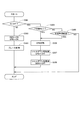
The power supply control process of this embodiment will be described with reference to the time chart of FIG. FIG. 7 shows the vehicle speed, the IG on / off state, the automatic parking control on / off state, the SBW control, the SBW-ECU50 on / off state, the BBW-ECU71 on / off state, and the EPB-ECU72 from the top with the common time axis as the horizontal axis. It shows the on / off state and EPB control. In FIG. 7, it is assumed that the shift-by-
時刻x10にて、運転者から指令により、自動駐車制御が実行される。自動駐車制御中は、シフトレンジの切り替えを繰り返し、所望の箇所に車両を駐車させる。図7では、R→D→Rとレンジが切り替えられるが、切り返しの回数や各レンジの継続時間等は問わない。 At time x10, automatic parking control is executed by a command from the driver. During automatic parking control, the shift range is repeatedly switched to park the vehicle at a desired location. In FIG. 7, the range is switched from R to D to R, but the number of turns and the duration of each range are not limited.
時刻x11にて、自動駐車制御が完了し、IGがオフされると、一点鎖線で示すように、目標シフトレンジがPレンジに切り替わる。シフトバイワイヤシステム2が正常の場合、破線で示すように、判定時間Xthが経過するより前のタイミングにて、Pレンジに切り替わる。図7では、IGオフ、自動駐車制御オフ、および、Pレンジへの切替指令が同時に行われるように記載されているが、例えば自動駐車用ECU75からPレンジへの切り替えが指令され、その後にIGがオフされるようにしてもよいし、IGオフをトリガとしてPレンジへの切り替えが指令されるようにしてもよく、制御順は問わない。
When the automatic parking control is completed and the IG is turned off at time x11, the target shift range is switched to the P range as shown by the alternate long and short dash line. When the shift-by-
時刻x11にてPレンジへの切り替えが指令されたにも関わらず、シフトレンジがPレンジに切り替わらないP不可異常が発生した場合、時刻x11から判定時間Xthが経過した時刻x12にて、EPB装置62を作動させる。また、EPB装置62の作動完了後の時刻x13にて、EPB制御を終了するとともに、シャットダウン処理後、EPB−ECU72をオフにする。また、EPB−ECU72をオフした後の時刻x14にて、BBW−ECU71をオフにする。図7では、P不可異常時について説明しているが、レンジ不一致異常の有無によらず、本実施形態では、SBW−ECU50、EPB−ECU72、BBW−ECU71の順に電源がオフされる。
If a P-impossible abnormality occurs in which the shift range does not switch to the P range even though the switch to the P range is commanded at the time x11, the EPB device is set at the time x12 when the determination time Xth has elapsed from the time x11. 62 is activated. Further, at the time x13 after the operation of the
図7では、BBW制御の記載を省略したが、自動駐車用EUC75からの指令等に応じて制御される。BBW制御終了タイミングは、EPB制御終了の時刻x13と同時でもよいし、時刻x13以降であってBBW−ECU71がオフされる時刻x14以前のいずれのタイミングとしてもよい。
Although the description of the BBW control is omitted in FIG. 7, the control is performed in response to a command or the like from the EUC75 for automatic parking. The BBW control end timing may be the same as the EPB control end time x13, or may be any timing after the time x13 and before the time x14 when the BBW-
以上説明したように、本実施形態の車両用制御装置100は、シフトバイワイヤシステム2、および、電動ブレーキシステム3を含む車両制御システム1を制御する。シフトバイワイヤシステム2は、モータ10の駆動を制御することでシフトレンジを切り替える。電動ブレーキシステム3は、BBWアクチュエータ65およびEPBアクチュエータ66の駆動を制御することで車両を制動させる。
As described above, the
車両用制御装置100は、シフト制御部およびブレーキ制御部を備える。本実施形態では、シフト制御部であるSBW−ECU50は、モータ10の駆動を制御する。ブレーキ制御部であるBBW−ECU71は、ブレーキアクチュエータであるBBWアクチュエータ65の駆動を制御する。ブレーキ制御部であるEPB−ECU72は、ブレーキアクチュエータであるEPBアクチュエータ66の駆動を制御する。車両の始動スイッチがオフされた場合、シフトバイワイヤシステム2のPレンジへの切替完了後、BBW−ECU71およびEPB−ECU72の電源をオフにする。
The
例えば自動駐車の完了後に、P不可異常が生じると、シフトバイワイヤシステム2にて車両を固定することができず、車両のずり下がり等が発生する虞がある。そこで本実施形態では、シフトバイワイヤシステム2のPレンジへの切り替え後に、BBW−ECU71およびEPB−ECU72の電源をオフにするようにしている。換言すると、シフトバイワイヤシステム2のP入れ完了までは、BBW−ECU71およびEPB−ECU72をオフにしない。これにより、P不可異常が発生した場合、電動ブレーキシステム3による車両固定を確実に行うことができるので、シフトバイワイヤシステム2に異常が生じた場合の安全性を確保可能である。
For example, if a P-impossible abnormality occurs after the completion of automatic parking, the vehicle cannot be fixed by the shift-by-
SBW−ECU50の電源がオフされた後、BBW−ECU71およびEPB−ECU72の電源がオフされる。本実施形態では、SBW−ECU50、EPB−ECU72、BBW−ECU71の順に電源がオフされる。これにより、P不可異常が発生した場合であっても、確実に車両固定を行うことができる。
After the power of the SBW-
電動ブレーキシステム3は、通電オフ後も制動状態を維持可能なEPB装置62を有する。シフトバイワイヤシステム2にてPレンジへの切り替えが不能となるP不可異常が生じた場合、EPB装置62を作動させた後、BBW−ECU71およびEPB−ECU72の電源をオフにする。これにより、P不可異常が発生した場合であっても、確実に車両固定を行うことができる。
The
(他の実施形態)
上記実施形態では、レンジ不一致異常が生じた場合、BBW装置61を作動させて車両を固定する。他の実施形態では、レンジ不一致異常が生じた場合、BBW装置61に加え、EPB装置62を作動させてもよい。また、BBW装置61に替えて、EPB装置62を作動させてもよい。上記実施形態では、電動ブレーキシステムには、BBWシステムおよびEPBシステムが含まれるが、いずれか一方がメカ式のものであってもよい。また、電動ブレーキシステムはブレーキ制御装置により制動を制御可能であれば、上記実施形態の構成に限らず、どのような構成であってもよい。
(Other embodiments)
In the above embodiment, when a range mismatch abnormality occurs, the
上記実施形態では、IGがオフされたときにシフト切替システムが正常であれば、SBW−ECU50の電源オフ、EPB−ECU72の電源オフ、BBW−ECU71の電源オフの順で行われる。また、IGがオフされたときにP不可異常が生じた場合、SBW−ECU50の電源オフ、EPB装置作動、EPB−ECU72の電源オフ、BBW−ECU71の電源オフの順で行われる。他の実施形態では、シフトバイワイヤシステムにおけるPレンジへの切替完了、または、電動ブレーキシステムによる車両固定完了後にブレーキ制御部の電源がオフにされるように構成されていればよく、上記の制御順は異なっていてもよい。また、電動ブレーキシステムとしてEPB装置を有していない場合、BBW−ECUの電源をオフにせず、BBW装置の作動を継続するようにしてもよい。
In the above embodiment, if the shift switching system is normal when the IG is turned off, the power of the SBW-
上記実施形態では、SBW−ECU、BBW−ECUおよびEPB−ECUが別途のECUとして設けられている。他の実施形態では、これらの少なくとも一部が1つのECUとして設けられていてもよい。この場合、各種情報の授受は、車両通信網を介さず、内部的に行われるようにすればよい。 In the above embodiment, the SBW-ECU, the BBW-ECU and the EPB-ECU are provided as separate ECUs. In other embodiments, at least some of these may be provided as one ECU. In this case, the exchange of various information may be performed internally without going through the vehicle communication network.
上記実施形態では、モータ回転角センサは、エンコーダである。他の実施形態では、モータ回転角センサは、エンコーダに限らず、レゾルバ等、どのようなものを用いてもよい。上記実施形態では、出力軸センサとしてポテンショメータを例示した。他の実施形態では、出力軸センサは、どのようなものであってもよく、例えば、各レンジ保証領域にてオンされるスイッチにより構成されてもよいし、非接触の磁気センサを用いてもよい。また、出力軸センサを省略してもよい。 In the above embodiment, the motor rotation angle sensor is an encoder. In another embodiment, the motor rotation angle sensor is not limited to the encoder, and any resolver or the like may be used. In the above embodiment, a potentiometer is exemplified as an output shaft sensor. In other embodiments, the output shaft sensor may be of any kind, for example, it may be configured by a switch that is turned on in each range guaranteed area, or a non-contact magnetic sensor may be used. Good. Further, the output shaft sensor may be omitted.
上記実施形態では、ディテントプレートには4つの谷部が設けられる。他の実施形態では、谷部の数は4つに限らず、いくつであってもよい。例えば、Pレンジと、Pレンジ以外のレンジであるnotPレンジに対応する2つの谷部が設けられていてもよい。シフトレンジ切替機構やパーキングロック機構等は、上記実施形態と異なっていてもよい。 In the above embodiment, the detent plate is provided with four valleys. In other embodiments, the number of valleys is not limited to four and may be any number. For example, two valleys corresponding to the P range and the notP range, which is a range other than the P range, may be provided. The shift range switching mechanism, the parking lock mechanism, and the like may be different from those in the above embodiment.
上記実施形態では、モータ軸と出力軸との間に減速機が設けられる。減速機の詳細について、上記実施形態では言及していないが、例えば、サイクロイド歯車、遊星歯車、モータ軸と略同軸の減速機構から駆動軸へトルクを伝達する平歯歯車を用いたものや、これらを組み合わせて用いたもの等、どのような構成であってもよい。また、他の実施形態では、モータ軸と出力軸との間の減速機を省略してもよいし、減速機以外の機構を設けてもよい。以上、本発明は、上記実施形態になんら限定されるものではなく、発明の趣旨を逸脱しない範囲において種々の形態で実施可能である。 In the above embodiment, a speed reducer is provided between the motor shaft and the output shaft. The details of the speed reducer are not mentioned in the above embodiment, but for example, cycloid gears, planetary gears, spur gears that transmit torque from a speed reduction mechanism substantially coaxial with the motor shaft to the drive shaft, and these. Any configuration may be used, such as a combination of the above. Further, in another embodiment, the speed reducer between the motor shaft and the output shaft may be omitted, or a mechanism other than the speed reducer may be provided. As described above, the present invention is not limited to the above-described embodiment, and can be implemented in various embodiments without departing from the spirit of the invention.
1・・・車両制御システム
2・・・シフトバイワイヤシステム(シフトレンジ切替システム)
3・・・電動ブレーキシステム
10・・・モータ(シフトアクチュエータ)
50・・・SBW−ECU(シフト制御部)
65・・・BBWアクチュエータ(ブレーキアクチュエータ)
66・・・EPBアクチュエータ(ブレーキアクチュエータ)
71・・・BBW−ECU(ブレーキ制御部)
72・・・EPB−ECU(ブレーキ制御部)
100・・・車両用制御装置
1 ...
3 ...
50 ... SBW-ECU (shift control unit)
65 ... BBW actuator (brake actuator)
66 ... EPB actuator (brake actuator)
71 ... BBW-ECU (brake control unit)
72 ... EPB-ECU (brake control unit)
100 ... Vehicle control device
Claims (1)
前記シフトアクチュエータの駆動を制御するシフト制御部(50)と、
前記ブレーキアクチュエータの駆動を制御するブレーキ制御部(71、72)と、
を備え、
前記電動ブレーキシステムは、通電オフ後の制動状態を維持可能な電動パーキングブレーキ装置(62)を有し、
車両の始動スイッチがオフされた場合、
前記シフトレンジ切替システムでのPレンジへの切り替えが完了した場合、または、P作動指令から判定時間が経過した場合、前記シフト制御部の電源をオフにし、
前記シフトレンジからP作動完了通知またはP不可異常が生じている旨の情報を前記ブレーキ制御部が受信した場合、もしくは、P作動指令から判定時間が経過した場合、前記電動パーキングブレーキ装置を作動させ、前記電動ブレーキ装置の作動完了後に前記ブレーキ制御部の電源をオフにする車両用制御装置。 A shift range switching system (2) that switches the shift range by controlling the drive of the shift actuator (10), and an electric brake system (3) that brakes the vehicle by controlling the drive of the brake actuators (65, 66). A vehicle control device that controls a vehicle control system (1) including the above.
A shift control unit (50) that controls the drive of the shift actuator, and
Brake control units (71, 72) that control the drive of the brake actuator, and
With
The electric brake system has an electric parking brake device (62) capable of maintaining a braking state after the power is turned off.
If the vehicle start switch is turned off
When the switching to the P range in the shift range switching system is completed, or when the determination time has elapsed from the P operation command, the power of the shift control unit is turned off.
When the brake control unit receives the P operation completion notification or the information that the P impossible abnormality has occurred from the shift range, or when the determination time has elapsed from the P operation command, the electric parking brake device is activated. , A vehicle control device that turns off the power of the brake control unit after the operation of the electric brake device is completed.
Priority Applications (5)
| Application Number | Priority Date | Filing Date | Title |
|---|---|---|---|
| JP2017226017A JP6881253B2 (en) | 2017-11-24 | 2017-11-24 | Vehicle control device |
| DE112018006012.8T DE112018006012T5 (en) | 2017-11-24 | 2018-11-16 | Vehicle control device |
| PCT/JP2018/042402 WO2019102934A1 (en) | 2017-11-24 | 2018-11-16 | Vehicle control device |
| CN201880072299.8A CN111344201B (en) | 2017-11-24 | 2018-11-16 | Vehicle control device |
| US16/871,372 US11112008B2 (en) | 2017-11-24 | 2020-05-11 | Vehicle control device |
Applications Claiming Priority (1)
| Application Number | Priority Date | Filing Date | Title |
|---|---|---|---|
| JP2017226017A JP6881253B2 (en) | 2017-11-24 | 2017-11-24 | Vehicle control device |
Publications (3)
| Publication Number | Publication Date |
|---|---|
| JP2019093962A JP2019093962A (en) | 2019-06-20 |
| JP2019093962A5 JP2019093962A5 (en) | 2020-01-09 |
| JP6881253B2 true JP6881253B2 (en) | 2021-06-02 |
Family
ID=66631857
Family Applications (1)
| Application Number | Title | Priority Date | Filing Date |
|---|---|---|---|
| JP2017226017A Active JP6881253B2 (en) | 2017-11-24 | 2017-11-24 | Vehicle control device |
Country Status (5)
| Country | Link |
|---|---|
| US (1) | US11112008B2 (en) |
| JP (1) | JP6881253B2 (en) |
| CN (1) | CN111344201B (en) |
| DE (1) | DE112018006012T5 (en) |
| WO (1) | WO2019102934A1 (en) |
Families Citing this family (5)
| Publication number | Priority date | Publication date | Assignee | Title |
|---|---|---|---|---|
| JP6863245B2 (en) | 2017-11-20 | 2021-04-21 | 株式会社デンソー | Shift range controller |
| JP6852658B2 (en) | 2017-11-24 | 2021-03-31 | 株式会社デンソー | Vehicle control device |
| JP2021165101A (en) * | 2020-04-08 | 2021-10-14 | マツダ株式会社 | Vehicle control device |
| JP2022144098A (en) * | 2021-03-18 | 2022-10-03 | 本田技研工業株式会社 | Vehicle control device |
| JP7414037B2 (en) * | 2021-04-28 | 2024-01-16 | 株式会社デンソー | Vehicle control device |
Family Cites Families (18)
| Publication number | Priority date | Publication date | Assignee | Title |
|---|---|---|---|---|
| JP2005180653A (en) | 2003-12-22 | 2005-07-07 | Denso Corp | Abnormality diagnostic device of motor driving system |
| JP4367620B2 (en) | 2003-12-22 | 2009-11-18 | 株式会社デンソー | Abnormality diagnosis device for motor drive system |
| JP4656067B2 (en) * | 2006-03-23 | 2011-03-23 | アイシン・エィ・ダブリュ株式会社 | Vehicle parking control system |
| US7731627B2 (en) * | 2006-03-23 | 2010-06-08 | Aisin Aw Co., Ltd. | Vehicle parking control system |
| JP4333755B2 (en) * | 2007-03-05 | 2009-09-16 | トヨタ自動車株式会社 | Vehicle parking system |
| DE102007042210B4 (en) * | 2007-09-05 | 2011-07-07 | ZF Friedrichshafen AG, 88046 | Method for automatically inserting a parking brake of an automatic or automated transmission of a motor vehicle |
| JP4525738B2 (en) * | 2007-11-13 | 2010-08-18 | 株式会社デンソー | Shift range switching device |
| JP5177043B2 (en) * | 2009-03-25 | 2013-04-03 | トヨタ自動車株式会社 | Vehicle control apparatus and control method |
| JP4894933B2 (en) * | 2009-06-04 | 2012-03-14 | 株式会社デンソー | Shift range switching device and parking lock device |
| JP4920732B2 (en) * | 2009-09-30 | 2012-04-18 | ジヤトコ株式会社 | Control device for shift-by-wire vehicle |
| JP5327149B2 (en) * | 2010-02-10 | 2013-10-30 | 株式会社デンソー | In-vehicle communication device |
| JP2013199165A (en) | 2012-03-23 | 2013-10-03 | Fuji Heavy Ind Ltd | Fail-safe device for shift-by-wire system |
| JP6492778B2 (en) | 2015-03-05 | 2019-04-03 | 株式会社デンソー | Range switching control device |
| CN106032141B (en) * | 2015-03-19 | 2019-01-29 | 比亚迪股份有限公司 | Parking braking control system, method and vehicle for vehicle |
| CN107097783A (en) * | 2017-04-10 | 2017-08-29 | 广州汽车集团股份有限公司 | P keeps off parking control method and system and the vehicle with the system |
| JP7009936B2 (en) | 2017-11-06 | 2022-01-26 | 株式会社デンソー | Shift range controller |
| JP6863245B2 (en) | 2017-11-20 | 2021-04-21 | 株式会社デンソー | Shift range controller |
| JP6852658B2 (en) | 2017-11-24 | 2021-03-31 | 株式会社デンソー | Vehicle control device |
-
2017
- 2017-11-24 JP JP2017226017A patent/JP6881253B2/en active Active
-
2018
- 2018-11-16 CN CN201880072299.8A patent/CN111344201B/en active Active
- 2018-11-16 DE DE112018006012.8T patent/DE112018006012T5/en active Pending
- 2018-11-16 WO PCT/JP2018/042402 patent/WO2019102934A1/en active Application Filing
-
2020
- 2020-05-11 US US16/871,372 patent/US11112008B2/en active Active
Also Published As
| Publication number | Publication date |
|---|---|
| CN111344201A (en) | 2020-06-26 |
| US20200271224A1 (en) | 2020-08-27 |
| JP2019093962A (en) | 2019-06-20 |
| WO2019102934A1 (en) | 2019-05-31 |
| DE112018006012T5 (en) | 2020-08-20 |
| CN111344201B (en) | 2022-04-26 |
| US11112008B2 (en) | 2021-09-07 |
Similar Documents
| Publication | Publication Date | Title |
|---|---|---|
| JP6852658B2 (en) | Vehicle control device | |
| JP6881253B2 (en) | Vehicle control device | |
| US9873414B2 (en) | Parking brake system for a vehicle | |
| JP4833097B2 (en) | Shift-by-wire device | |
| US9233666B2 (en) | Shift-by-wire vehicle and method to verify securement | |
| US9073504B2 (en) | Vehicle immobilizer method and system | |
| US10501080B2 (en) | Electric parking brake usage for vehicle powertrain out of operation conditions | |
| US20130314222A1 (en) | Electronic parking brake system and method of indicating malfunction of parking brake switch | |
| JP2009541133A (en) | Parking brake mechanism for automobiles | |
| EP1845495A1 (en) | Electric Parking Brake System | |
| JP2007170546A (en) | Vehicle control system | |
| US10221940B2 (en) | Neutral state movement protection for an automatic transmission | |
| JP6729495B2 (en) | Shift range control device | |
| JP2007032819A (en) | Vehicle control system | |
| JP6992310B2 (en) | Shift-by-wire controller | |
| JP5846394B2 (en) | Actuator control device | |
| JP6809335B2 (en) | Vehicle control device | |
| KR101382996B1 (en) | System and method for reducing turning radius of vehicle | |
| KR20160107955A (en) | control apparatus of acceleration | |
| WO2018193533A1 (en) | Electronic control device and control method for achieving safe parking lock | |
| KR102600290B1 (en) | Controller Integrated Electronic Shift Control System | |
| WO2015141043A1 (en) | Parking lock mechanism control device and control method | |
| JP2021142784A (en) | Brake device and vehicle | |
| JP4811382B2 (en) | Parking brake device | |
| JP2004314861A (en) | Driving mode changeover control device of transfer |
Legal Events
| Date | Code | Title | Description |
|---|---|---|---|
| A521 | Request for written amendment filed |
Free format text: JAPANESE INTERMEDIATE CODE: A523 Effective date: 20191122 |
|
| A621 | Written request for application examination |
Free format text: JAPANESE INTERMEDIATE CODE: A621 Effective date: 20200515 |
|
| TRDD | Decision of grant or rejection written | ||
| A01 | Written decision to grant a patent or to grant a registration (utility model) |
Free format text: JAPANESE INTERMEDIATE CODE: A01 Effective date: 20210406 |
|
| A61 | First payment of annual fees (during grant procedure) |
Free format text: JAPANESE INTERMEDIATE CODE: A61 Effective date: 20210419 |
|
| R151 | Written notification of patent or utility model registration |
Ref document number: 6881253 Country of ref document: JP Free format text: JAPANESE INTERMEDIATE CODE: R151 |
|
| R250 | Receipt of annual fees |
Free format text: JAPANESE INTERMEDIATE CODE: R250 |