WO2019098280A1 - 構造物における直角構造の位置又は位置の変化量を推定するためのシステム、方法、プログラム、及びプログラムを記録した記録媒体 - Google Patents
構造物における直角構造の位置又は位置の変化量を推定するためのシステム、方法、プログラム、及びプログラムを記録した記録媒体 Download PDFInfo
- Publication number
- WO2019098280A1 WO2019098280A1 PCT/JP2018/042302 JP2018042302W WO2019098280A1 WO 2019098280 A1 WO2019098280 A1 WO 2019098280A1 JP 2018042302 W JP2018042302 W JP 2018042302W WO 2019098280 A1 WO2019098280 A1 WO 2019098280A1
- Authority
- WO
- WIPO (PCT)
- Prior art keywords
- intensity
- image
- point
- crude oil
- sar
- Prior art date
- Legal status (The legal status is an assumption and is not a legal conclusion. Google has not performed a legal analysis and makes no representation as to the accuracy of the status listed.)
- Ceased
Links
Images













Classifications
-
- G—PHYSICS
- G01—MEASURING; TESTING
- G01S—RADIO DIRECTION-FINDING; RADIO NAVIGATION; DETERMINING DISTANCE OR VELOCITY BY USE OF RADIO WAVES; LOCATING OR PRESENCE-DETECTING BY USE OF THE REFLECTION OR RERADIATION OF RADIO WAVES; ANALOGOUS ARRANGEMENTS USING OTHER WAVES
- G01S13/00—Systems using the reflection or reradiation of radio waves, e.g. radar systems; Analogous systems using reflection or reradiation of waves whose nature or wavelength is irrelevant or unspecified
- G01S13/88—Radar or analogous systems specially adapted for specific applications
- G01S13/89—Radar or analogous systems specially adapted for specific applications for mapping or imaging
- G01S13/90—Radar or analogous systems specially adapted for specific applications for mapping or imaging using synthetic aperture techniques, e.g. synthetic aperture radar [SAR] techniques
- G01S13/9021—SAR image post-processing techniques
- G01S13/9027—Pattern recognition for feature extraction
-
- G—PHYSICS
- G01—MEASURING; TESTING
- G01F—MEASURING VOLUME, VOLUME FLOW, MASS FLOW OR LIQUID LEVEL; METERING BY VOLUME
- G01F22/00—Methods or apparatus for measuring volume of fluids or fluent solid material, not otherwise provided for
-
- G—PHYSICS
- G01—MEASURING; TESTING
- G01F—MEASURING VOLUME, VOLUME FLOW, MASS FLOW OR LIQUID LEVEL; METERING BY VOLUME
- G01F23/00—Indicating or measuring liquid level or level of fluent solid material, e.g. indicating in terms of volume or indicating by means of an alarm
- G01F23/22—Indicating or measuring liquid level or level of fluent solid material, e.g. indicating in terms of volume or indicating by means of an alarm by measuring physical variables, other than linear dimensions, pressure or weight, dependent on the level to be measured, e.g. by difference of heat transfer of steam or water
- G01F23/28—Indicating or measuring liquid level or level of fluent solid material, e.g. indicating in terms of volume or indicating by means of an alarm by measuring physical variables, other than linear dimensions, pressure or weight, dependent on the level to be measured, e.g. by difference of heat transfer of steam or water by measuring the variations of parameters of electromagnetic or acoustic waves applied directly to the liquid or fluent solid material
- G01F23/284—Electromagnetic waves
-
- G—PHYSICS
- G01—MEASURING; TESTING
- G01S—RADIO DIRECTION-FINDING; RADIO NAVIGATION; DETERMINING DISTANCE OR VELOCITY BY USE OF RADIO WAVES; LOCATING OR PRESENCE-DETECTING BY USE OF THE REFLECTION OR RERADIATION OF RADIO WAVES; ANALOGOUS ARRANGEMENTS USING OTHER WAVES
- G01S13/00—Systems using the reflection or reradiation of radio waves, e.g. radar systems; Analogous systems using reflection or reradiation of waves whose nature or wavelength is irrelevant or unspecified
- G01S13/88—Radar or analogous systems specially adapted for specific applications
- G01S13/89—Radar or analogous systems specially adapted for specific applications for mapping or imaging
- G01S13/90—Radar or analogous systems specially adapted for specific applications for mapping or imaging using synthetic aperture techniques, e.g. synthetic aperture radar [SAR] techniques
-
- G—PHYSICS
- G06—COMPUTING OR CALCULATING; COUNTING
- G06T—IMAGE DATA PROCESSING OR GENERATION, IN GENERAL
- G06T7/00—Image analysis
-
- G—PHYSICS
- G06—COMPUTING OR CALCULATING; COUNTING
- G06T—IMAGE DATA PROCESSING OR GENERATION, IN GENERAL
- G06T7/00—Image analysis
- G06T7/70—Determining position or orientation of objects or cameras
Definitions
- the present invention relates to a system, a method, a program, and a recording medium for recording a program for estimating the position or the amount of change in position of a rectangular structure in a structure, more specifically, from a horizontal surface or a predetermined horizontal direction.
- the present invention takes as an example the height of the floating roof of the floating roof tank or the amount of change in height without the need to collect a large amount of high resolution SAR images frequently and without the need to create 3D data.
- a first surface having a horizontal surface or a surface inclined by a predetermined angle from the horizontal direction, and a vertical surface or a second portion having a surface inclined by the predetermined angle from the vertical direction are orthogonal surfaces
- a structure having a right-angled structure forming the first and second portions in a first direction which is a direction perpendicular to the horizontal surface or a surface inclined by a predetermined angle from the horizontal direction
- One aspect of the present invention is a structure having a plurality of identical structures in a target area, the first part having a horizontal surface or a surface inclined by a predetermined angle from the horizontal direction. And a vertical surface or a structure having a right-angled structure in which a second part having a surface inclined by the predetermined angle from the vertical direction forms an orthogonal surface, the predetermined angle from the horizontal surface or horizontal direction Position variation estimation system for estimating the variation of the position of the first portion in the first direction, which is a direction perpendicular to the inclined plane, and wherein the SAR intensity image including the target region of a plurality of time periods is A superimposed image generation unit that generates superimposed images so that the points at the same position coincide with each other, and a structure that acquires the center of each of the plurality of structures with respect to the superimposed images.
- Center position take An average image generation unit configured to average the intensities of SAR intensity images of a plurality of time periods and generate an average image, with respect to a SAR intensity image of a desired one of the plurality of structures, In the average image, on the central line which is a straight line in the range direction passing the point where the intensity in the SAR intensity image of one structure is maximum, on the side farther from the synthetic aperture radar than the center of the desired structure
- a reference point determination unit for determining a reference point which is a point at which the intensity is maximum, and a center line in the SAR intensity image of the structure at a desired time are farther from the synthetic aperture radar than the center of the desired structure.
- the far-side intensity maximum point which is the point where the intensity is maximum on the side, is determined, and based on the distance between the point and the reference point, the position of the first part in the first direction.
- a system comprising a position change amount calculating unit for obtaining the amount of change.
- horizontal means a concept including not only perfect horizontal but also substantially horizontal.
- a system, a method, a program, and a recording medium recording the program capable of determining the position or the amount of change of the position of the first portion in the first direction which is a direction perpendicular to the inclined surface is provided. It can be.
- FIG. 1 illustrates the principle of a first embodiment of the present invention. It is a figure showing functional composition of a height change amount presumption system concerning a 1st embodiment of the present invention. It is a figure which shows the example of the hardware constitutions of the height change amount estimation system which concerns on the 1st Embodiment of this invention. It is a flow chart of an example of height change amount presumption processing concerning a 1st embodiment of the present invention. It is a flow chart of an example of height change amount presumption processing concerning a 1st embodiment of the present invention. It is a flow chart of an example of height change amount presumption processing concerning a 1st embodiment of the present invention.
- FIG. 2 illustrates the principle underlying the process for matching tank positions; It is a figure explaining position amendment of an azimuth direction. It is a figure explaining position amendment of a range direction. It is a figure which shows the example of a template image. It is a figure which shows the example of the calculation result of the likelihood with respect to a superimposition image. It is a figure which shows the example of the center of each calculated
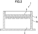
- FIG. 1 is a schematic perspective view of a floating roof tank.
- FIG. 2 is a cross-sectional view taken along the line II-II of FIG.
- the floating roof tank 1 includes a bottomed cylindrical container portion 2 and a disk-like floating roof 3 in contact with the container portion 2.
- the crude oil 4 is accommodated in the container unit 2, and the floating roof 3 directly floats on the crude oil 4.
- the floating roof tank 1 has a right-angled structure in which the angle between the side wall (second portion) of the container portion 2 and the floating roof 3 (first portion) is at right angles.
- the floating roof 3 moves vertically in the vertical direction by the amount of the crude oil 4 contained in the container unit 2. That is, the height of the floating roof 3 is proportional to the amount of the crude oil 4 contained in the container portion 2.
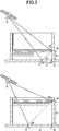
- FIG. 3 is a diagram showing the principle of the first embodiment of the present invention.
- the SAR intensity image is for displaying on the image the time (distance) until the electromagnetic wave transmitted from the synthetic aperture radar S to the observation target point is reflected from the observation target point and returns. Therefore, when the observation target point has a height, the observation target point is displayed on the side of the synthetic aperture radar S on the SAR intensity image than the actual position. Specifically, it is displayed at the position of the intersection of the circumference and the ground surface, whose radius is the distance from the synthetic aperture radar S to the point to be observed. Referring to FIG. 3, the contact points P and P ′ of the floating roof 3 and the container portion 2 are displayed at positions R and R ′ on the SAR side of the actual positions Q and Q ′.
- the heights of the observation points P and P '(line segment PQ, size of line segment P'Q') are h, h ', lines
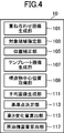
- FIG. 4 is a diagram showing a functional configuration of the height change amount estimation system according to the first embodiment of the present invention.
- the height change amount estimation system 10 includes a superimposed image generation unit 101, a target area designation unit 103, a position correction unit 105, a template image generation unit 107, a structure center position acquisition unit 109, an average image generation unit 111, and reference point determination.
- the unit 113 includes a height change amount calculation unit 115 and a crude oil reserve calculation unit 117.
- the superposition image generation unit 101 is a superposition image obtained by superimposing SAR intensity images including target regions of a plurality of times input to the superposition image generation unit 101 such that points at the same position coincide with each other.
- the target area designation unit 103 designates an analysis target area in the superimposed image.
- the position correction unit 105 sets, as a center line, a straight line in the range direction passing through a point at which the intensity is maximum for each of the images of the plurality of structures cut out from the target area in the superimposed image. Move the images of the cut out structures so that they overlap each other, and move the images of the cut out structures relative to each other to a position where the intensity distribution on the center line matches in the range direction Match the position.
- the template image generation unit 107 generates a template image by superimposing images of a plurality of cut out structures whose positions are matched with each other.
- the structure center position acquisition unit 109 acquires the center position of each of the plurality of structures in the superimposed image.
- the center position of each structure can be determined by performing template matching using a template image. Moreover, when the position of each structure is already known, you may acquire the value.
- the average image generation unit 111 generates an average image by averaging the intensities of the SAR intensity images of a plurality of periods with respect to the SAR intensity image of a desired structure among the plurality of structures.
- the reference point determination unit 113 determines that the center position, which is a straight line in the range direction passing through the point at which the intensity in the SAR intensity image of one structure is maximum in the generated average image, than the center position of the desired structure. A reference point at which the intensity is maximum on the side far from the synthetic aperture radar is determined.
- the height change amount calculation unit 115 (position change amount calculation unit) has a maximum intensity on the side farther from the synthetic aperture radar than the center position of the desired structure on the center line of the SAR intensity image of the structure at the desired time. Change the height (position in the first direction) of the horizontal portion (first portion) based on the distance between the far-side intensity maximum point and the reference point. Determine the quantity.
- the crude oil storage amount calculation unit 117 obtains the amount of change in the crude oil storage amount of each tank by multiplying the calculated amount of change in the height of the roof portion and the bottom area of the crude oil storage tank. Further, the total amount of change in crude oil stock of each tank is determined to determine the amount of change in crude oil stock of the entire crude oil stockpiling base.
- FIG. 5 is a diagram showing an example of a hardware configuration of the height change amount estimation system 1 according to the present embodiment.
- the height change amount estimation system 1 includes a CPU 130a, a RAM 130b, a ROM 130c, an external memory 130d, an input unit 130e, an output unit 130f, and a communication unit 130g.
- the RAM 130 b, the ROM 130 c, the external memory 130 d, the input unit 130 e, the output unit 130 f, and the communication unit 130 g are connected to the CPU 130 a via the system bus 130 h.
- Each part of the height change amount estimation system 1 is realized by using various programs stored in the ROM or the external memory as a resource using the CPU, RAM, ROM, external memory, input part, output part, communication part, etc. Ru.
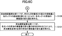
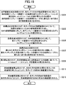
- 6A to 6B are flowcharts of an example of the height change amount estimation process according to the first embodiment of the present invention.
- SAR intensity images of the crude oil storage base 5 at multiple times are input to the superimposed image generation unit 101, and the superimposed image generation unit 101 sets the SAR intensity images of the crude oil storage base 5 at multiple locations in the same position.
- a superimposed image 500 is generated so that the points coincide with each other (S101).
- a method of superimposing so that the points at the same position coincide with each other is known in the interference SAR analysis technique and the like, and thus detailed description will be omitted.
- the superposition is performed such that the intensity of each pixel of the superposition image 500 is the minimum value among the intensities of the corresponding pixels of the SAR intensity images at a plurality of times. This makes it possible to reduce noise generated in individual SAR intensity images.
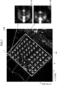
- An example of the obtained superimposed image is shown in FIG.
- the target area designation unit 103 designates an analysis target area 501 in the superimposed image 500 (S103).
- the designation of the analysis target area may be performed by a human designating the area on the superimposed image 500. For example, when the tank position information is already known, the computer is used based on the position information. It may be performed by In the present embodiment, the crude oil storage base 5 is designated as an analysis target area.
- a template image used to obtain the center position of the tank 1 by template matching is generated.
- images of a plurality of appropriate tanks in the analysis target area in the superimposed image 500 are cut out (S105).
- the directions of orthogonal sides are cut out into a square image in which the azimuth direction and the range direction become, the shape of the cut out image is not limited to this, and any suitable shape may be used.
- the clipping of the image of the tank 1 may be performed by a human designating an area on the superimposed image 500, or, for example, when position information such as the center position of the tank 1 is already known, It may be performed by a computer based on the position information.
- An example of the cut out image is shown in FIG.
- FIG. 8 is a diagram showing the principle underlying the process for aligning the positions of the tanks.
- the intensity of the electromagnetic wave reflected from the observation object is higher than the intensity of the electromagnetic wave reflected from the portion of the observation object whose tangent plane is orthogonal to the range direction.
- the tank 1 of the present embodiment has a cylindrical shape, the intersection points W and Q of the straight line L in the range direction passing through the center position of the tank 1 and the circumference of the bottom surface of the tank on the side wall 2a of the tank 1
- the intensity of the reflected wave from the portion extending in the vertical direction is observed to be larger than the other portions. Therefore, if the straight lines in the range direction passing through the points at which the intensities in each of the images of tank A and tank B become maximum are made to be center lines, move the center lines so that the center lines overlap each other. Matches.
- FIG. 9 is a diagram for explaining position correction in the azimuth direction.
- the maximum value of intensity is determined for each image line in the range direction, and the distribution of the intensity maximum value in the azimuth direction is determined (S107).
- the center lines are moved to overlap with each other (S109).
- the method of determining the center line is not limited to this, and for example, a point at which the intensity in the image of each tank is maximum may be determined, and a straight line in the range direction passing through the point may be used as the center line.
- FIG. 10 is a diagram for explaining position correction in the range direction.
- the intensity distribution on the image line of the center line determined for each tank is determined.
- the intensity distribution of tank A and tank B is as shown in FIG.
- the images of the tanks are mutually moved to a position where the intensity distribution on the center line of each tank matches.
- the value of convolution is obtained while changing the position of another tank (tank B) with respect to a specific tank (tank A), and the other tank (tank B) is obtained at the position where the value of convolution becomes maximum. ) Is moved (S111).
- the matching method is not limited to the above based on the value of convolution as described above, and, for example, another tank (tank B) is moved so as to match the position of maximum strength. Any suitable technique can be used.
- the template image generation unit 107 superposes the images of the tanks whose positions coincide with each other in this manner, and generates a template image 503 (S113).
- the superposition is performed such that the intensity of each pixel of the template image 503 is the minimum value of the intensities of the corresponding pixels of the images of the plurality of tanks. This makes it possible to reduce the noise generated in the images of the individual tanks.
- An example of the obtained superimposed image is shown in FIG.
- the method of superposing the images of the tanks is not limited to this, and, for example, the superimposition is performed so that the intensity of each pixel of the template image 503 is the average value of the intensities of the corresponding pixels of the images of multiple tanks. You may go.
- the center position of the template image 503 is on the determined center line in the azimuth direction.
- the center position in the range direction has a slight shift between the positions of tank A and tank B as described above, when the center of tank A is designated as an image cut out or as a known position, It may be a designated position of the tank A.
- the position of the tank A may be reduced by an average of the displacement amount of the position of the tank B (moving amount of the tank B) in the matching of the positions of the plurality of tanks B with respect to the tank A described above.
- the structure center position acquisition unit 109 obtains the center position of each tank in the superimposed image 500 by performing template matching using the generated template image 503.
- the template image used for template matching is not limited to one generated by the above-described method, and may be prepared in advance by an arbitrary method. For example, a person may select an appropriate tank image from the superimposed image 500. Specifically, the value (likelihood) of convolution is obtained while changing the position of the template image 503 with respect to the superimposed image 500 (S115).
- FIG. 12 is a diagram showing an example of the calculation result of the likelihood for the superimposed image 500. As shown in FIG.
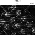
- FIG. 13 is a diagram showing an example of the determined center position of each tank.
- the central position of each tank may acquire its value if the position of each tank is already known, and further, a template image of that value may be prepared and fine correction may be performed.
- the average image generation unit 111 averages the intensities of the SAR intensity images of a plurality of times to generate an average image (S119).
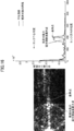
- FIG. 14 is a diagram showing the intensity distribution on the center line in the average image of the generated tank.
- the reference point determination unit 113 is a point on the center line of the generated average image of each tank that is a point at which the intensity is maximum on the side farther from the synthetic aperture radar than the center position of each tank obtained in the above step. Find a point (S121).
- the height change amount calculation unit 115 is located on the center line of the SAR intensity image of each tank 1 at the far side, which is the point where the intensity is maximum on the side farther from the synthetic aperture radar than the center position of each tank.
- the intensity maximum point is determined, and based on the distance between the far-side intensity maximum point and the reference point determined above, the amount of change in height of the floating roof 3 is determined.
- a search range of the far-side intensity maximum point is set with respect to the reference point.
- FIG. 15 shows an example of the reference point and the search range.
- the far-side intensity maximum point which is the point at which the intensity is maximum on the side farther from the synthetic aperture radar than the center position of each tank, is determined (S123).
- the number of pixels from the reference point to the far side intensity maximum point is determined (S125). Since the distance from the reference point to the far-side intensity maximum point is the product of the number of pixels from the reference point to the far-side intensity maximum point and the range resolution per pixel, referring to the above equation (1), the tank of the average image
- the amount of change in height from the height (reference height) of the floating roof 3 of the (Variation of height) (Number of pixels from reference point to far-side intensity maximum point) ⁇ (Range resolution per pixel) ⁇ tan ⁇ (2)
- the variation amount of the height of the floating roof 3 from the reference height is obtained by the equation (2) (S127).
- the crude oil storage amount calculation unit 117 obtains the change amount of the storage amount of crude oil of each tank 1 by multiplying the calculated fluctuation amount of the height of the floating roof 3 and the bottom area of each tank 1 (S129).
- the bottom area of each tank 1 can be acquired by any appropriate method such as using a known value, obtaining an SAR intensity image, or the like. Then, the total amount of change in the amount of crude oil stored in each tank is determined to determine the amount of change in the amount of crude oil stored in the entire crude oil storage base 5 (S131).
- the amount of change in the height of the floating roof of the floating roof tank is taken as an example even when using an inexpensive L-band SAR which is extremely difficult to identify and analyze crude oil storage tanks in the as-is observation
- the amount of change in height of the horizontal portion of the right-angled structure can be determined. Therefore, it is possible to obtain the amount of change in the height of the horizontal portion of the right-angled structure, taking the amount of change in the height of the floating roof of the floating roof tank as an example.
- extraction processing of the crude oil storage tank is automated by machine learning processing using time-series data, and estimation processing of the amount of change in height of the floating roof of the extracted crude oil storage tank is also automated. There is.
- FIG. 17 is a diagram showing the principle of the second embodiment of the present invention.
- FIG. 18 is a diagram showing a functional configuration of the height estimation system according to the second embodiment of the present invention.
- FIG. 19 is a flowchart of an example of height change amount estimation processing according to the second embodiment of the present invention.
- An example of the principle, the height estimation system, and the height estimation process according to the second embodiment of the present invention will be described with reference to FIGS. 17 to 19 and the like.
- the portions corresponding to FIGS. 1 to 16 are denoted by the same reference numerals, and the description overlapping with the first embodiment will be omitted.
- the hardware configuration of the height estimation system according to the second embodiment is the same as that of the first embodiment, and thus the description thereof will be omitted.
- the floating roof 3 is displayed closer to the synthetic aperture radar S than the actual position on the SAR intensity image.
- the tank 1 has a height, so that the electromagnetic wave transmitted from the synthetic aperture radar S is not irradiated, and a portion 505 which is a shadow in the SAR intensity image is generated. If the position of the shadow 505a corresponding to directly below the floating roof 3 and the position of the image of the floating roof 3 in the shadow portion 505 are known, the value of d, which is the size of the line segment RQ, is known. (3) The height h of the floating roof 3 can be obtained from (3).
- the position of the shadow 505a corresponding to the position directly below the floating roof 3 is determined by template matching using the shadow template image 507 corresponding to the shadow 505a, and the position of the image 509 of the floating roof 3 is calculated using the floating roof 3
- the height h of the floating roof 3 is obtained by the template matching using the floating roof template image 509 corresponding to the image 509 of FIG.
- the height estimation system 20 includes a horizontal part nearest point determination unit 203, a shadow nearest point determination unit 203, a height calculation unit 205, and a crude oil storage amount calculation unit 207.
- the horizontal part nearest point determination unit 203 (first part nearest point determination unit) performs template matching on the image of the horizontal part of the SAR intensity image of the structure using the horizontal part template image (first partial template image).
- the horizontal portion closest point (first portion closest point) which is the closest point to the synthetic aperture radar of the horizontal portion template image at the matching position is performed.
- the shadow nearest point determination unit 203 performs template matching using the shadow template image on the shadow image and the peripheral edge image of the structure on the synthetic aperture radar side of the SAR intensity image of the structure, and is most matched
- the nearest shadow point which is the point closest to the synthetic aperture radar of the shadow template image at the position, is determined.
- the height calculation unit 205 obtains the height of the horizontal part (the position of the first part in the first direction) based on the distance between the nearest part of the horizontal part and the nearest point of the shadow.
- the crude oil storage amount calculation unit 207 obtains the crude oil storage amount of the crude oil storage tank by multiplying the obtained height of the roof portion and the bottom area of the crude oil storage tank. In addition, the crude oil stockpiling amount of the whole crude oil stockpiling base is obtained by finding the sum of the crude oil stocking amount of each tank.
- the horizontal part nearest point determination unit 203 performs template matching on the image of the floating roof 3 of the SAR intensity image 504 of each tank using the floating roof template image 509, and the floating roof template image 509 at the most matched position.
- a floating roof closest point U which is the point closest to the synthetic aperture radar S, is determined.
- the value of convolution is obtained while changing the position of the floating roof template image 511 corresponding to the image 509 of the floating roof 3 created in advance, and convolution is performed.
- a floating roof nearest point U which is a point closest to the synthetic aperture radar S of the floating roof template image 511 at a position where the value of the maximum value of the value of.
- the shadow nearest point determination unit 203 uses the shadow template image 507 as a template for the image of the shadow portion 505 of the SAR intensity image 504 of each tank and the image of the peripheral portion 506 on the synthetic aperture radar S side of each tank 1. Matching is performed, and the closest shadow point T which is the point closest to the synthetic aperture radar S of the shadow template image 507 at the most matching position is determined. Specifically, a SAR inverse intensity image in which the inverse of the intensity is taken is generated for the SAR intensity image 504 of each tank, and the SAR inverse intensity image corresponds to the image of the shadow portion 505 created in advance. A convolution value is obtained while changing the position of the shadow template image 507 (S203).
- the intensity of the image of the peripheral portion 506 on the synthetic aperture radar S side of each tank is increased. Evaluate the location.
- the values of both of the obtained convolutions are comprehensively determined, and the closest shadow point T, which is the point closest to the synthetic aperture radar S of the shadow template image 507 at the most matching position, is determined (S207).
- the method of generating the SAR inverse intensity image is not limited to the method of taking the inverse of the intensity of the SAR intensity image, and can be generated by any other appropriate method.
- the height calculation unit 205 calculates the above equation (3) based on the distance between the floating roof nearest point U and the shadow nearest point T obtained in the above step. According to 3), the height of the floating roof 3 is obtained (S209).
- the crude oil storage amount calculation unit 207 multiplies the height of the floating roof 3 and the bottom area of each tank to obtain the storage amount of crude oil in each tank (S211). Then, the total amount of crude oil stored in each tank is determined to determine the amount of crude oil stored in the entire crude oil storage base 5 (S213).
- a rectangular structure with a floating roof of the floating roof tank as an example is used.
- the height of the horizontal part can be determined. Therefore, it is possible to obtain the height of the horizontal portion of the right-angled structure, for example, the height of the floating roof of the floating roof tank, at low cost and without the need to create 3D data.
- FIG. 20 is a diagram showing the principle of the third embodiment of the present invention.
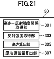
- FIG. 21 is a diagram showing a functional configuration of the height estimation system according to the second embodiment of the present invention.
- FIG. 22 is a flowchart of an example of height change amount estimation processing according to the third embodiment of the present invention.
- An example of the principle, the height estimation system, and the height estimation process according to the third embodiment of the present invention will be described with reference to FIGS. 20 to 22 and the like.
- parts corresponding to FIG. 1 to FIG. 18 will be assigned the same reference numerals and overlapping descriptions with the first and second embodiments will be omitted.
- the hardware configuration of the height estimation system according to the third embodiment is the same as that of the first embodiment, and thus the description thereof will be omitted.
- FIG. 20 is a diagram showing the principle of the third embodiment of the present invention.
- a floating roof tank generally used as a crude oil tank will be described as an example.
- the intensity of the reflected wave observed by the synthetic aperture radar is proportional to the radar cross section of the object to be observed.
- the radar cross section of the perpendicular structure is large, and when the height of the floating roof 3 is large, the radar cross section of the rectangular structure is small. Therefore, the intensity of the reflected wave observed by the synthetic aperture radar increases when the height of the floating roof 3 is small, and decreases when the height of the floating roof 3 is large.
- the reflected wave is the reflection of the height of the horizontal part and the electromagnetic wave transmitted from the synthetic aperture radar to the right-angled structure by the right-angled structure. From the relationship and the strength of the acquired reflected wave, the height of the horizontal portion can be obtained from the relationship with the strength of the light source by measurement or simulation.
- the height estimation system 30 includes a height-reflection intensity relationship acquisition unit 301, a reflected wave intensity acquisition unit 303, a height calculation unit 305, and a crude oil storage amount calculation unit 307.
- the height-reflection intensity relationship acquisition unit 301 transmits the height of the horizontal portion (the position of the first portion in the first direction) and the synthetic aperture radar to the rectangular structure.
- the electromagnetic wave obtains the relationship with the intensity of the reflected wave reflected by the right-angled structure.
- the reflected wave intensity acquisition unit 303 acquires the intensity of the reflected wave formed by the electromagnetic wave transmitted from the synthetic aperture radar to the orthogonal structure and reflected by the orthogonal structure.
- the height calculating unit 305 (position calculating unit) is a reflected wave obtained by reflecting the intensity of the acquired reflected wave, the height of the horizontal portion, and the electromagnetic wave transmitted from the synthetic aperture radar to the orthogonal structure by the orthogonal structure.
- the height of the horizontal part is determined based on the relationship with the strength of the
- the crude oil storage amount calculation unit 307 obtains the crude oil storage amount of the crude oil storage tank by multiplying the calculated height of the roof portion and the bottom area of the crude oil storage tank.
- the crude oil stockpiling amount of the whole crude oil stockpiling base is obtained by finding the sum of the crude oil stocking amount of each tank.
- the height-reflection intensity relationship acquisition unit 301 measures the relationship between the height of the floating roof 3 and the intensity of the reflected wave of the electromagnetic wave transmitted from the synthetic aperture radar to the right-angled structure and reflected by the right-angled structure. Acquired by simulation etc. For example, in the case of actual measurement, the height of the floating roof 3 of each tank 1 of the crude oil storage base 5 is often different from each other, so the measured value of the height of the floating roof 3 of each tank at a certain time is obtained (S301 ). Also, SAR observation is performed at a certain time, and in the same way as in the first embodiment, on the center line in the SAR intensity image of each tank at that time, on the side farther from the synthetic aperture radar than the central position of each tank.
- the far-side intensity maximum point which is the point at which the intensity is maximum, is determined, and the intensity of the point is acquired (S303). Then, the relationship between the two is obtained from the measured value of the height of the floating roof 3 of each tank and the intensity of the far-side intensity maximum point in the SAR intensity image (S305).
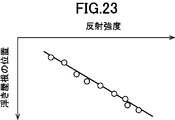
- FIG. 23 shows an example of the relationship between the measured height of the floating roof 3 and the intensity of the far-side intensity maximum point in the SAR intensity image.
- the plurality of data required to obtain the relationship between the actual measurement value of the height of the floating roof and the intensity of the far-side intensity maximum point in the SAR intensity image is the floating roof of a plurality of tanks of one period.
- the measured height and the strength data of the far-side strength maximum point in the SAR strength image were used, but the measured height and SAR strength of the floating roof height of multiple seasons of one tank or multiple seasons of multiple tanks
- the intensity of the far-side intensity maximum point in the image may be used.
- the reflected wave intensity acquisition unit 303 acquires the intensity of the reflected wave resulting from reflection of the electromagnetic wave transmitted from the SAR to the orthogonal structure by the orthogonal structure. Specifically, as in the first embodiment, on the center line of the SAR intensity image of each tank 1, the intensity is maximized on the side farther from the synthetic aperture radar than the center position of each tank 1 The far-side intensity maximum point is determined, and the intensity of the point is acquired (S307).
- the height calculation unit 305 determines the strength of the acquired reflected wave, the height of the horizontal portion, and the strength of the reflected wave formed by the electromagnetic wave transmitted from the synthetic aperture radar to the rectangular structure and reflected by the rectangular structure. Determine the height of the horizontal part based on the relationship. Specifically, based on the acquired strength of the far-side strength maximum point of each tank and the relationship between the height of the floating roof 3 of the tank 1 and the strength of the far-side strength maximum point, the height of the floating roof 3 (S309).
- the crude oil storage amount calculation unit 307 obtains the crude oil storage amount of each tank by multiplying the height of the floating roof 3 thus obtained and the bottom area of each tank (S311). Then, the total amount of crude oil stored in each tank is determined to determine the amount of crude oil stored in the entire crude oil storage base 5 (S313).
- a rectangular structure with a floating roof of the floating roof tank as an example is used.
- the height of the horizontal part can be determined. Therefore, it is possible to obtain the height of the horizontal portion of the right-angled structure, for example, the height of the floating roof of the floating roof tank, at low cost and without the need to create 3D data.
- FIG. 24 is a diagram showing an example of an SAR intensity image of a wide area low resolution observation mode at a certain time.
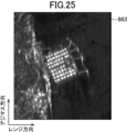
- FIG. 25 is a diagram showing an example of a superimposed image of SAR intensity images of wide-range low-resolution observation modes at a plurality of times.
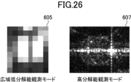
- FIG. 26 is a diagram showing an example of a SAR intensity image of a wide range low resolution observation mode and a SAR intensity image of a high resolution observation mode of a certain tank.
- FIG. 27 is a flowchart of an example of height change amount estimation processing according to the fourth embodiment of the present invention. An example of a height estimation system and a height estimation process according to the fourth embodiment of the present invention will be described with reference to FIGS. 24 to 27 and FIG. 8 and the like.
- FIG. 27 the portions corresponding to FIG. 22 are assigned the same reference numerals, and the description overlapping the first to third embodiments is omitted.
- the functional configuration of the height estimation system according to the fourth embodiment is the same as that of the third embodiment, and the hardware configuration of the height estimation system according to the fourth embodiment is the first embodiment. Since it is the same as the above, the explanation is omitted.
- the intensity is maximum on the side farther from the synthetic aperture radar than the central position of each tank
- the far-side intensity maximum point which is the point where
- a wide area low resolution observation mode such as ScanSAR mode
- ScanSAR mode the far-side intensity maximum point corresponding point corresponding to the far-side intensity maximum point on the center line is determined, and the intensity of that point is calculated. By acquiring it, the height of the floating roof is obtained.
- the height-reflection intensity relationship acquisition unit 301 is a reflection of the height of the floating roof 3 and the electromagnetic wave transmitted from the synthetic aperture radar to the right-angled structure by the right-angled structure.
- the relationship with the strength of the wave is acquired by measurement, simulation or the like.
- the height of the floating roof 3 of each tank 1 of the crude oil storage base 5 is often different from each other, so the measured value of the height of the floating roof 3 of each tank at a certain time is obtained (S301 ).
- the SAR intensity image 601 is acquired by the SAR observation of the wide area low resolution observation mode such as ScanSAR mode performed at a certain time (S401).
- a superimposed image 603 is generated in which the SAR intensity images of the wide-range low-resolution observation mode of the crude oil storage base 5 at multiple times are superimposed so that the points at the same position coincide. (S403).
- the superposition is performed such that the intensity of each pixel of the superposition image 603 is the minimum value of the intensities of the corresponding pixels of the SAR intensity images of a plurality of times.
- a difference image is generated by calculating the difference between the intensity of each pixel of the SAR intensity image at a certain time and the intensity of the corresponding pixel of the superimposed image (S405).
- the point at which this difference is the maximum is the far-side intensity maximum point corresponding point, which is a point corresponding to the far-side intensity maximum point on the center line, which is obtained in the first embodiment. I will explain in detail.
- the tank 1 of the present embodiment has a cylindrical shape
- the straight line L in the range direction passing through the center position of the tank 1 and the circle of the bottom of the tank on the side wall 2 a of the tank 1 The intensity of the reflected wave from the portion extending in the vertical direction through the intersection points W and Q with the circumference is observed to be larger than the other portions.
- the portion extending in the vertical direction is constant, passing through the point of intersection W on the side close to the synthetic aperture radar on the side wall 2a of the tank 1 that reflects the electromagnetic wave transmitted from the synthetic aperture radar.
- the portion passing through the intersection point Q on the side far from the synthetic aperture radar, which reflects the electromagnetic wave transmitted from the synthetic aperture radar, is the portion of the side wall 2a above the floating roof 3 and varies with time. Is normal. Therefore, in the SAR intensity image of a plurality of times, the intensity of the point corresponding to the intersection point W is constant, and the intensity of the point corresponding to the intersection point Q usually varies. That is, the superimposed image 603 is obtained by superimposing the intensity of each pixel of the superimposed image 603 to the minimum value among the intensities of the corresponding pixels of the SAR intensity images of a plurality of times.
- the intensity of the point corresponding to the intersection point Q is generally smaller than the intensity of the point corresponding to the intersection point W. Therefore, unless the height of floating roof 3 at a certain time is the same as the minimum value of the height of floating roof 3 corresponding to the SAR intensity image used to generate superimposed image 603, in the difference image, intersection W Since the intensity of the point corresponding to is zero and the intensity of the point corresponding to the intersection point Q is a non-zero value, it is possible to distinguish the point corresponding to the intersection point W and the point corresponding to the intersection point Q A point corresponding to Q is a far-side intensity maximum point corresponding point, which is a point corresponding to the far-side intensity maximum point on the center line, which is determined in the first embodiment.
- the relationship between the two is determined from the measured value of the height of the floating roof 3 of each tank and the intensity of the far-side intensity maximum point corresponding point in the SAR intensity image (S409).
- the reflected wave intensity relationship acquiring unit 303 acquires the intensity of the reflected wave formed by the electromagnetic wave transmitted from the SAR to the orthogonal structure and being reflected by the orthogonal structure. Specifically, in the same manner as steps S401 to S407 described above, the far-side intensity maximum point corresponding point of each tank is determined, and the intensity of the point is acquired (S411).
- the height calculation unit 305 determines the strength of the acquired reflected wave, the height of the horizontal portion, and the strength of the reflected wave formed by the electromagnetic wave transmitted from the synthetic aperture radar to the rectangular structure and reflected by the rectangular structure. Based on the relationship, the height of the horizontal portion is determined. Specifically, the floating roof is based on the acquired strength of the far side strength maximum point corresponding point of each tank and the relationship between the height of the floating roof 3 of the tank 1 and the strength of the far side strength maximum point corresponding point The height of 3 is obtained (S413).
- the crude oil storage amount calculation unit 307 obtains the crude oil storage amount of each tank by multiplying the height of the floating roof 3 thus obtained and the bottom area of each tank (S311). Then, the total amount of crude oil stored in each tank is determined to determine the amount of crude oil stored in the entire crude oil storage base 5 (S313).
- the height of the floating roof of the floating roof tank is taken as an example even when using a wide area low resolution observation mode such as ScanSAR mode where the crude oil storage tank is extremely difficult to identify and analyze in the as-is observation
- the height of the horizontal part of the right-angled structure can be determined. Therefore, it is possible to obtain the height of the horizontal part of the right-angled structure taking the height of the floating roof of the floating roof tank as an example, without the need to create 3D data.
- the side wall and the floating roof of the floating roof type tank are illustrated and described as the perpendicular structure to be observed, but it is a matter of course that the present invention can be used for observation of other rectangular structures.
- the right-angled structure is not limited to a structure in which a horizontal portion having a horizontal surface and a vertical portion having a vertical surface form an orthogonal surface, and a surface inclined by a predetermined angle from the horizontal direction
- the first portion and the second portion having a surface inclined at the same angle as the predetermined angle from the vertical direction may form an orthogonal surface.
Landscapes
- Engineering & Computer Science (AREA)
- Physics & Mathematics (AREA)
- Remote Sensing (AREA)
- Radar, Positioning & Navigation (AREA)
- General Physics & Mathematics (AREA)
- Electromagnetism (AREA)
- Computer Vision & Pattern Recognition (AREA)
- Computer Networks & Wireless Communication (AREA)
- Theoretical Computer Science (AREA)
- Fluid Mechanics (AREA)
- Artificial Intelligence (AREA)
- Thermal Sciences (AREA)
- Radar Systems Or Details Thereof (AREA)
- Measurement Of Levels Of Liquids Or Fluent Solid Materials (AREA)
- Image Analysis (AREA)
Abstract
浮き屋根式タンクの浮き屋根の高さ又は高さの変化量を例とする水平方向の面又は水平方向から所定の角度だけ傾斜した面を有する第1の部分と、鉛直方向の面又は鉛直方向から前記所定の角度だけ傾斜した面を有する第2の部分が直交面を形成する直角構造を有する構造物における、前記水平方向の面又は水平方向から所定の角度だけ傾斜した面に垂直な方向である第1の方向の第1の部分の位置又は位置の変化量を求めることができるシステム、方法、プログラム、及びプログラムを記録した記録媒体であって、構造物のSAR強度画像を用いて、高分解能のSAR画像を大量に高頻度で集める必要がなく、3Dデータの作成の必要がない、構造物における直角構造の位置又は位置の変化量を推定するためのシステム、方法、プログラム、及びプログラムを記録した記録媒体。
Description
本発明は、構造物における直角構造の位置又は位置の変化量を推定するためのシステム、方法、プログラム、及びプログラムを記録した記録媒体、より詳細には、水平方向の面又は水平方向から所定の角度だけ傾斜した面を有する第1の部分と、鉛直方向の面又は鉛直方向から前記所定の角度だけ傾斜した面を有する第2の部分が直交面を形成する直角構造を有する構造物における、前記水平方向の面又は水平方向から所定の角度だけ傾斜した面に垂直な方向である第1の方向の第1の部分の位置又は位置の変化量を推定するためのシステム、方法、プログラム、及びプログラムを記録した記録媒体に関する。
浮き屋根式の原油タンクの原油備蓄量を合成開口レーダ(以下、「SAR」ともいう。)により推定する手法が提案されている(下記特許文献1)。この手法においては、高分解能SARを用いて、画像データからの多方向観測によりタンクの3Dデータを作成し、浮き屋根の高さを算出することにより、原油備蓄量を求める。
しかしながら、上記手法は、高分解能のSAR画像を大量に高頻度で集めるのは難しいこと、高分解能SARが高価であること、画像データからの多方向観測によりタンクの3Dデータを作成する必要があるといった問題点がある。
そこで、本発明は、高分解能のSAR画像を大量に高頻度で集める必要がなく、3Dデータの作成の必要がない、浮き屋根式タンクの浮き屋根の高さ又は高さの変化量を例とする、水平方向の面又は水平方向から所定の角度だけ傾斜した面を有する第1の部分と、鉛直方向の面又は鉛直方向から前記所定の角度だけ傾斜した面を有する第2の部分が直交面を形成する直角構造を有する構造物における、前記水平方向の面又は水平方向から所定の角度だけ傾斜した面に垂直な方向である第1の方向の第1の部分の位置又は位置の変化量を求めることができるシステム、方法、プログラム、及びプログラムを記録した記録媒体を提供することを目的の1つとする。
本発明の1つの態様は、対象領域内に存在する、複数の、同一の構造を有する構造物であって、水平方向の面又は水平方向から所定の角度だけ傾斜した面を有する第1の部分と、鉛直方向の面又は鉛直方向から前記所定の角度だけ傾斜した面を有する第2の部分が直交面を形成する直角構造を有する構造物における、前記水平方向の面又は水平方向から所定の角度だけ傾斜した面に垂直な方向である第1の方向の前記第1の部分の位置の変化量を推定する位置変化量推定システムであって、複数の時期の、対象領域を含むSAR強度画像を、同じ位置の地点が一致するように重ね合わせた、重ね合わせ画像を生成する重ね合わせ画像生成部と、前記重ね合わせ画像に対して、前記複数の前記構造物の各々の中心を取得する構造物中心位置取得部と、前記複数の前記構造物のうちの所望の前記構造物のSAR強度画像について、複数の時期のSAR強度画像に対して強度について平均をとり、平均画像を生成する平均画像生成部と、前記平均画像において、1つの構造物のSAR強度画像における強度が最大となる点を通るレンジ方向の直線である中心線上で、前記所望の前記構造物の前記中心よりも合成開口レーダから遠い側において強度が最大となる点である基準点を求める基準点決定部と、所望の時期の前記構造物のSAR強度画像における中心線上で、前記所望の前記構造物の前記中心よりも合成開口レーダから遠い側において強度が最大となる点である遠方側強度最大点を求め、その点と前記基準点との距離に基づいて、前記であって、第1の部分の前記第1の方向の位置の変化量を求める位置変化量算出部とを含むシステムを提供するものである。
本明細書及び特許請求の範囲において、「水平」は、完全な水平のみならず、略水平も含んだ概念を意味する。
上記構成を有する本発明によれば、安価なL-band SARやScanSARモード等の広域低分解能観測モードを用いることができるので、高分解能のSAR画像を大量に高頻度で集める必要がなく、3Dデータの作成の必要がない、浮き屋根式タンクの浮き屋根の高さ又は高さの変化量を例とする水平方向の面又は水平方向から所定の角度だけ傾斜した面を有する第1の部分と、鉛直方向の面又は鉛直方向から前記所定の角度だけ傾斜した面を有する第2の部分が直交面を形成する直角構造を有する構造物における、前記水平方向の面又は水平方向から所定の角度だけ傾斜した面に垂直な方向である第1の方向の第1の部分の位置又は位置の変化量を求めることができるシステム、方法、プログラム、及びプログラムを記録した記録媒体を提供することができる。
以下、本発明の実施形態について図面を参照して説明する。
(第1の実施形態)
まず、本発明の第1の実施形態の原理について説明する。原油タンクとして一般的な浮き屋根式タンクを例として説明する。図1は、浮き屋根式タンクの斜視模式図である。図2は、図1のII-II断面図である。浮き屋根式タンク1は、有底円筒状の容器部2と、容器部2に接する円板状の浮き屋根3を備える。容器部2には原油4が収容され、原油4上に浮き屋根3が直接浮かぶ構造を有している。よって、浮き屋根式タンク1は、容器部2の側壁(第2の部分)と浮き屋根3(第1の部分)のなす角度が直角となる直角構造を有する。また、浮き屋根3は、容器部2に収容された原油4の量によって、鉛直方向に上下に移動する。すなわち、浮き屋根3の高さが、容器部2に収容された原油4の量に比例する。
まず、本発明の第1の実施形態の原理について説明する。原油タンクとして一般的な浮き屋根式タンクを例として説明する。図1は、浮き屋根式タンクの斜視模式図である。図2は、図1のII-II断面図である。浮き屋根式タンク1は、有底円筒状の容器部2と、容器部2に接する円板状の浮き屋根3を備える。容器部2には原油4が収容され、原油4上に浮き屋根3が直接浮かぶ構造を有している。よって、浮き屋根式タンク1は、容器部2の側壁(第2の部分)と浮き屋根3(第1の部分)のなす角度が直角となる直角構造を有する。また、浮き屋根3は、容器部2に収容された原油4の量によって、鉛直方向に上下に移動する。すなわち、浮き屋根3の高さが、容器部2に収容された原油4の量に比例する。
図3は、本発明の第1の実施形態の原理を示す図である。SAR強度画像は、合成開口レーダSから観測対象点へと送出された電磁波が、観測対象点から反射されて戻ってくるまでの時間(距離)を画像上に表示するものである。よって、観測対象点に高さがある場合、SAR強度画像上では、観測対象点は、実際の位置よりも合成開口レーダS側に表示される。具体的には、合成開口レーダSから観測対象点までの距離を半径とする円周と地表面との交点の位置に表示される。これを図3についてみると、浮き屋根3と容器部2の接点P、P'は、実際の位置Q、Q'よりもSAR側の位置R、R'に表示される。
合成開口レーダSから観測対象点(浮き屋根3と容器部2の接点)P、P'までの距離が十分大きい場合は、線分SPと線分PR、線分S'P'と線分P'R'はそれぞれ直交し、電磁波の入射角は等しいと見なせるから、観測対象点P、P'の高さ(線分PQ、線分P'Q'の大きさ)をh、h'、線分RQ、線分R'Q'の大きさをd、d'とすると、観測対象点の高さの変化量h-h'は、
h-h'=dtanθ-d'tanθ'≒(d-d')tanθ・・・(1)
と求めることができる。
h-h'=dtanθ-d'tanθ'≒(d-d')tanθ・・・(1)
と求めることができる。
図4は、本発明の第1の実施形態に係る高さ変化量推定システムの機能構成を示す図である。
高さ変化量推定システム10は、重ね合わせ画像生成部101、対象領域指定部103、位置補正部105、テンプレート画像生成部107、構造物中心位置取得部109、平均画像生成部111、基準点決定部113、高さ変化量算出部115、原油備蓄量算出部117を備える。
重ね合わせ画像生成部101は、重ね合わせ画像生成部101に入力された、複数の時期の、対象領域を含むSAR強度画像を、同じ位置の地点が一致するように重ね合わせた、重ね合わせ画像を生成する。
対象領域指定部103は、重ね合わせ画像において解析対象領域を指定する。
位置補正部105は、重ね合わせ画像における対象領域から切り出された複数の構造物の画像の各々について、強度が最大となる点を通るレンジ方向の直線を中心線とし、アジマス方向については、中心線が互いに重なるように、切り出された複数の構造物の画像を移動させ、レンジ方向については、中心線上の強度分布がマッチングする位置まで、切り出された複数の構造物の画像を互いに移動させてその位置を一致させる。
テンプレート画像生成部107は、互いの位置が一致された切り出された複数の構造物の画像を重ね合わせてテンプレート画像を生成する。
構造物中心位置取得部109は、重ね合わせ画像に対して、複数の構造物の各々の中心位置を取得する。各構造物の中心位置は、テンプレート画像を用いてテンプレートマッチングを行うことにより求めることができる。また、各構造物の位置が既に分かっている場合は、その値を取得してもよい。
平均画像生成部111は、複数の構造物のうちの所望の構造物のSAR強度画像について、複数の時期のSAR強度画像に対して強度について平均をとり、平均画像を生成する。
基準点決定部113は、生成された平均画像において、1つの構造物のSAR強度画像における強度が最大となる点を通るレンジ方向の直線である中心線上で、所望の構造物の中心位置よりも合成開口レーダから遠い側において強度が最大となる点である基準点を求める。
高さ変化量算出部115(位置変化量算出部)は、所望の時期の構造物のSAR強度画像における中心線上で、所望の構造物の中心位置よりも合成開口レーダから遠い側において強度が最大となる点である遠方側強度最大点を求め、その遠方側強度最大点と基準点との距離に基づいて、水平部(第1の部分)の高さ(第1の方向の位置)の変化量を求める。
原油備蓄量算出部117は、求めた屋根部の高さの変化量と原油備蓄用タンクの底面積を乗じることにより、各タンクの原油の備蓄量の変化量を求める。また、各タンクの原油の備蓄量の変化量の総和を求めることにより、原油備蓄基地全体の原油の備蓄量の変化量を求める。
図5は、本実施形態に係る高さ変化量推定システム1のハードウエア構成の例を示す図である。高さ変化量推定システム1は、CPU130a、RAM130b、ROM130c、外部メモリ130d、入力部130e、出力部130f、通信部130gを含む。RAM130b、ROM130c、外部メモリ130d、入力部130e、出力部130f、通信部130gは、システムバス130hを介して、CPU130aに接続されている。
高さ変化量推定システム1の各部は、ROMや外部メモリに記憶された各種プログラムが、CPU、RAM、ROM、外部メモリ、入力部、出力部、通信部等を資源として使用することで実現される。
以上のシステム構成を前提に、本発明の第1の実施形態に係る高さ変化量推定システムの高さ変化量推定処理の例を、図6A~図16等を参照して、以下に説明する。本実施形態では、上記で説明したタンクが行列状に設置された原油備蓄基地のSAR強度画像を例として説明する。
図6A~図6Bは、本発明の第1の実施形態にかかる高さ変化量推定処理の一例のフローチャートである。
まず、複数の時期の原油備蓄基地5のSAR強度画像が重ね合わせ画像生成部101に入力され、重ね合わせ画像生成部101は、複数の時期の原油備蓄基地5のSAR強度画像を、同じ位置の地点が一致するように重ね合わせた重ね合わせ画像500を生成する(S101)。同じ位置の地点が一致するように重ね合わせる手法は、干渉SAR解析技術等において周知であるので、詳しい説明は省略する。本実施形態では、重ね合わせ画像500の各画素の強度が、複数の時期のSAR強度画像の対応する画素の強度のうちの最小値となるように重ね合わせが行われる。これにより、個々のSAR強度画像で発生しているノイズを低減することができる。得られた重ね合わせ画像の例を図7に示す。
続いて、対象領域指定部103は、重ね合わせ画像500における解析対象領域501を指定する(S103)。解析対象領域の指定は、人間が重ね合わせ画像500上で領域を指定することによって行われてもよいし、例えば、タンクの位置情報が既に分かっている場合には、その位置情報に基づいてコンピュータにより行われてもよい。本実施形態では、原油備蓄基地5が解析対象領域として指定されている。
次に、タンク1の中心位置をテンプレートマッチングにより求めるために用いるテンプレート画像を生成する。まず、重ね合わせ画像500における解析対象領域内の適切な複数のタンクの画像を切り出す(S105)。本実施形態では、直交する辺の方向が、アジマス方向とレンジ方向となるような正方形の画像に切り出すが、切り出す画像の形状はこれに限定されるものではなく、任意の適切な形状とすることができる。タンク1の画像の切り出しは、人間が重ね合わせ画像500上で領域を指定することによって行われてもよいし、例えば、タンク1の中心位置等の位置情報が既に分かっている場合には、その位置情報に基づいてコンピュータにより行われてもよい。切り出した画像の例を図7に示す。
図7から分かるように、切り出した画像内で、タンクAとタンクBの位置がずれている。そこで、タンクAとタンクBの位置を一致させるために、以下の処理を行うが、ここで、その処理に用いる原理について説明する。なお、図7の例は、理解の容易のために、タンクAとタンクBの位置のずれを強調しているが、実際は、タンクAとタンクBの位置のずれはわずかである。
図8は、タンクの位置を一致させるための処理の基礎となる原理を示す図である。合成開口レーダにおいて、観測対象物から反射された電磁波の強度は、観測対象物の、その接平面がレンジ方向と直交する部分から反射された電磁波の強度が、他の部分よりも大きく観測される。本実施形態のタンク1は、円筒形状を有しているので、タンク1の側壁2aの、タンク1の中心位置を通るレンジ方向の直線Lとタンクの底面の円周との交点W、Qを通り、鉛直方向に延びる部分からの反射波の強度が、他の部分よりも大きく観測される。したがって、タンクA、タンクBの画像のそれぞれにおける強度が最大となる点を通るレンジ方向の直線を中心線として、互いの中心線が重なり合うように互いを移動すれば、アジマス方向については、その位置が一致する。
位置補正部105は、以下の処理を行う。図9は、アジマス方向の位置補正を説明する図である。まず、図9に示すように、レンジ方向の各画像ラインについて強度の最大値を求め、強度最大値のアジマス方向の分布を求める(S107)。そして、強度最大値のアジマス方向の分布において最大値をとる画像ラインを中心線として、互いの中心線が重なり合うように互いを移動させる(S109)。中心線の求め方はこれに限定されるものではなく、例えば各タンクの画像における強度が最大となる点を求めて、その点を通るレンジ方向の直線を中心線としてもよい。
続いて、各タンクのレンジ方向の位置を一致させる。図10は、レンジ方向の位置補正を説明する図である。まず各タンクについて求められた中心線の画像ライン上の強度分布を求める。例えば、タンクA、タンクBの強度分布は図10のようになる。この各タンクの中心線上の強度分布がマッチングする位置まで、各タンクの画像を互いに移動させる。具体的には、特定のタンク(タンクA)に対して他のタンク(タンクB)の位置を変えながらコンボリューションの値を求め、コンボリューションの値が最大となる位置に他のタンク(タンクB)を移動させる(S111)。マッチング手法としては、上述のようなコンボリューションの値に基づくものに限定されるものではなく、例えば、最大強度をとる位置が一致するように他のタンク(タンクB)を移動させる等、他の任意の適切な手法を用いることができる。
テンプレート画像生成部107は、このようにして互いの位置が一致されたタンクの画像を重ね合わせて、テンプレート画像503を生成する(S113)。本実施形態では、テンプレート画像503の各画素の強度が、複数タンクの画像の対応する画素の強度のうちの最小値となるように重ね合わせが行われる。これにより、個々のタンクの画像で発生しているノイズを低減することができる。得られる重ね合わせ画像の例を図11に示す。タンクの画像の重ね合わせ手法は、これに限定されるものでなく、例えば、テンプレート画像503の各画素の強度が、複数タンクの画像の対応する画素の強度の平均値となるように重ね合わせを行ってもよい。
ここで、テンプレート画像503の中心位置は、アジマス方向については、求められた中心線上にある。一方、レンジ方向の中心位置は、上述のようにタンクAとタンクBの位置のずれはわずかであるから、画像切り出し時や既知の位置としてタンクAの中心が指定されたような場合は、そのタンクAの指定位置としてもよい。また、上述のタンクAに対する複数のタンクBの位置のマッチングにおけるタンクBの位置のずれ量(タンクBの移動量)の平均だけ、タンクAの指定位置から減じた位置としてもよい。
続いて、構造物中心位置取得部109は、重ね合わせ画像500における各タンクの中心位置を、生成したテンプレート画像503を用いてテンプレートマッチングを行うことにより求める。テンプレートマッチングに用いるテンプレート画像は、上記のような手法により生成されるものに限定されるものではなく、任意の手法で予め用意されていればよい。例えば、重ね合わせ画像500から適切なタンクの画像を人間が選択してもよい。具体的には、重ね合わせ画像500に対してテンプレート画像503の位置を変えながらコンボリューションの値(尤度)を求める(S115)。図12は、重ね合わせ画像500に対する尤度の算出結果の例を示す図である。この尤度に対して、適切な閾値により二値化を行い、二値化により1の値となった箇所について、モルフォロジー処理による複数検出箇所の統合を行い、統合された各箇所について、尤度が最大となる点を各タンクの中心位置として求める(S117)。図13は、求められた各タンクの中心位置の例を示す図である。各タンクの中心位置は、各タンクの位置が既に分かっている場合は、その値を取得してもよいし、更に、その値のテンプレート画像を用意して、微修正を行ってもよい。
次に、平均画像生成部111は、各タンクのSAR強度画像について、複数の時期のSAR強度画像に対して強度について平均をとり、平均画像を生成する(S119)。
図14は、生成されたタンクの平均画像における中心線上の強度分布を示す図である。基準点決定部113は、生成された各タンクの平均画像において、中心線上で、上記ステップで求めた各タンクの中心位置よりも、合成開口レーダから遠い側において強度が最大となる点である基準点を求める(S121)。
そして、高さ変化量算出部115は、各タンク1の各時期のSAR強度画像における中心線上で、各タンクの中心位置よりも合成開口レーダから遠い側において強度が最大となる点である遠方側強度最大点を求め、その遠方側強度最大点と上で求めた基準点との距離に基づいて、浮き屋根3の高さの変化量を求める。具体的には、まず、基準点に対して遠方側強度最大点の探索範囲を設定する。図15に、基準点と探索範囲の例を示す。そして、その探索範囲内で、各タンクの中心位置よりも合成開口レーダから遠い側において強度が最大となる点である遠方側強度最大点を求める(S123)。図16に、遠方側強度最大点の探索と基準点との関係を説明する図を示す。そして、基準点から遠方側強度最大点までの画素数を求める(S125)。基準点から遠方側強度最大点までの距離は、基準点から遠方側強度最大点までの画素数と画素当たりのレンジ分解能の積であるから、上記式(1)を参照すると、平均画像のタンクの浮き屋根3の高さ(基準高さ)から高さの変動量は、
(高さの変動量)=(基準点から遠方側強度最大点までの画素数)×(画素当たりのレンジ分解能)×tanθ・・・(2)
により求めることができるので、式(2)により、基準高さからの浮き屋根3の高さの変動量を求める(S127)。
(高さの変動量)=(基準点から遠方側強度最大点までの画素数)×(画素当たりのレンジ分解能)×tanθ・・・(2)
により求めることができるので、式(2)により、基準高さからの浮き屋根3の高さの変動量を求める(S127)。
更に、原油備蓄量算出部117は、求めた浮き屋根3の高さの変動量と各タンク1の底面積を乗じることにより、各タンク1の原油の備蓄量の変化量を求める(S129)。各タンク1の底面積は、既知の値を用いたり、SAR強度画像がら求めたり等適切な任意の手法で取得することができる。そして、各タンクの原油の備蓄量の変化量の総和を求めることにより、原油備蓄基地5全体の原油の備蓄量の変化量を求める(S131)。
本実施形態によれば、そのままの観測では原油備蓄タンクの特定や解析が極めて困難な安価なL-band SARを用いても、浮き屋根式タンクの浮き屋根の高さの変化量を例とする直角構造の水平部の高さの変化量を求めることができる。よって、低コストで、3Dデータの作成の必要がない、浮き屋根式タンクの浮き屋根の高さの変化量を例とする直角構造の水平部の高さの変化量を求めることができる。
また、本実施形態によれば、時系列データを用いた機械学習処理によって原油備蓄タンクの抽出処理が自動化され、抽出した原油備蓄タンクの浮き屋根の高さの変化量の推定処理も自動化されている。
(第2の実施形態)
図17は、本発明の第2の実施形態の原理を示す図である。図18は、本発明の第2の実施形態に係る高さ推定システムの機能構成を示す図である。図19は、本発明の第2の実施形態にかかる高さ変化量推定処理の一例のフローチャートである。これらの図17~図19等を参照して、本発明の第2の実施形態に係る原理、高さ推定システム及び高さ推定処理の例を説明する。図17~図19において、図1~図16に対応する部分には同一の符号を付し、第1の実施形態と重複する説明は省略する。また、第2の実施形態に係る高さ推定システムのハードウエア構成は、第1の実施形態と同様であるので説明を省略する。
図17は、本発明の第2の実施形態の原理を示す図である。図18は、本発明の第2の実施形態に係る高さ推定システムの機能構成を示す図である。図19は、本発明の第2の実施形態にかかる高さ変化量推定処理の一例のフローチャートである。これらの図17~図19等を参照して、本発明の第2の実施形態に係る原理、高さ推定システム及び高さ推定処理の例を説明する。図17~図19において、図1~図16に対応する部分には同一の符号を付し、第1の実施形態と重複する説明は省略する。また、第2の実施形態に係る高さ推定システムのハードウエア構成は、第1の実施形態と同様であるので説明を省略する。
まず、本実施形態の原理について説明する。第1の実施形態と同様に、原油タンクとして一般的な浮き屋根式タンクを例として、図17を参照して説明する。
第1の実施形態で説明したように、SAR強度画像上では、浮き屋根3は、実際の位置よりも合成開口レーダS側に表示される。そして、観測対象点P(浮き屋根3と容器部2の接点)の高さ(線分PQの大きさ)hは、線分RQの大きさをdとすると、
h=dtanθ・・・(3)
により求めることができる。入射角θは既知であるから、dの値が分かれば、浮き屋根3の高さを求めることができる。
h=dtanθ・・・(3)
により求めることができる。入射角θは既知であるから、dの値が分かれば、浮き屋根3の高さを求めることができる。
一方、図17から分かるように、タンク1が高さを有することによって、合成開口レーダSから送出された電磁波が照射されず、SAR強度画像で影になる部分505が生じる。この影の部分505のうち、浮き屋根3の直下に対応する影505aの位置と、浮き屋根3の画像の位置が分かれば、線分RQの大きさであるdの値が分かり、上の式(3)より、浮き屋根3の高さhを求めることができる。
本実施形態は、浮き屋根3の直下に対応する影505aの位置を、影505aに対応する影テンプレート画像507を用いてテンプレートマッチングで求めると共に、浮き屋根3の画像509の位置を、浮き屋根3の画像509に対応する浮き屋根テンプレート画像509を用いてテンプレートマッチングで求めることにより、浮き屋根3の高さhを求めるものである。
高さ推定システム20は、水平部最近点決定部203、影最近点決定部203、高さ算出部205、原油備蓄量算出部207を備える。
水平部最近点決定部203(第1部分最近点決定部)は、構造物のSAR強度画像の水平部の画像に対して、水平部テンプレート画像(第1部分テンプレート画像)を用いてテンプレートマッチングを行い、マッチングした位置における水平部テンプレート画像の合成開口レーダに最も近い点である水平部最近点(第1部分最近点)を求める。
影最近点決定部203は、構造物のSAR強度画像の、影の画像及び構造物の合成開口レーダ側の周縁部の画像に対して、影テンプレート画像を用いてテンプレートマッチングを行い、最もマッチングした位置における前記影テンプレート画像の合成開口レーダに最も近い点である影最近点を求める。
高さ算出部205(位置算出部)は、水平部最近点と影最近点との距離に基づいて、水平部の高さ(第1の部分の第1の方向の位置)を求める。
原油備蓄量算出部207は、求めた屋根部の高さと前記原油備蓄用タンクの底面積を乗じることにより、原油備蓄用タンクの原油の備蓄量を求める。また、各タンクの原油の備蓄量の総和を求めることにより、原油備蓄基地全体の原油の備蓄量を求める。
以上のシステム構成を前提に、本発明の第2の実施形態に係る高さ推定システムの高さ推定処理の例を以下に説明する。
水平部最近点決定部203は、各タンクのSAR強度画像504の浮き屋根3の画像に対して、浮き屋根テンプレート画像509を用いてテンプレートマッチングを行い、最もマッチングした位置における浮き屋根テンプレート画像509の合成開口レーダSに最も近い点である浮き屋根最近点Uを求める。具体的には、各タンク1のSAR強度画像504に対して、予め作成された、浮き屋根3の画像509に対応する浮き屋根テンプレート画像511の位置を変えながらコンボリューションの値を求め、コンボリューションの値が最大となる位置の浮き屋根テンプレート画像511の合成開口レーダSに最も近い点である浮き屋根最近点Uを求める(S201)。
影最近点決定部203は、各タンクのSAR強度画像504の影の部分505の画像及び各タンク1の合成開口レーダS側の周縁部506の画像に対して、影テンプレート画像507を用いてテンプレートマッチングを行い、最もマッチングした位置における影テンプレート画像507の合成開口レーダSに最も近い点である影最近点Tを求める。具体的には、各タンクのSAR強度画像504について、強度の逆数をとったSAR逆強度画像を生成し、SAR逆強度画像に対して、予め作成された、影の部分505の画像に対応する影テンプレート画像507の位置を変えながらコンボリューションの値を求める(S203)。また、SAR強度画像504に対して、影テンプレート画像507の位置を変えながらコンボリューションの値を求める(S205)ことによって、各タンクの合成開口レーダS側の周縁部506の画像の強度が大きくなる箇所を評価する。得られた両方のコンボリューションの値を総合的に判断して、最もマッチングした位置の影テンプレート画像507の合成開口レーダSに最も近い点である影最近点Tを求める(S207)。SAR逆強度画像の生成手法としては、SAR強度画像の強度の逆数をとる手法に限定されるものでなく、他の任意の適切な手法によって生成することができる。
線分UTの大きさは、線分RQの大きさと等しいから、高さ算出部205は、上記ステップで求められた浮き屋根最近点Uと影最近点Tとの距離に基づいて、上記式(3)により、浮き屋根3の高さを求める(S209)。
更に、原油備蓄量算出部207は、求めた浮き屋根3の高さと各タンクの底面積を乗じることにより、各タンクの原油の備蓄量を求める(S211)。そして、各タンクの原油の備蓄量の総和を求めることにより、原油備蓄基地5全体の原油の備蓄量を求める(S213)。
本実施形態によれば、そのままの観測では原油備蓄タンクの特定や解析が極めて困難な安価なL-band SARを用いても、浮き屋根式タンクの浮き屋根の高さを例とする直角構造の水平部の高さを求めることができる。よって、低コストで、3Dデータの作成の必要がない、浮き屋根式タンクの浮き屋根の高さを例とする直角構造の水平部の高さを求めることができる。
(第3の実施形態)
図20は、本発明の第3の実施形態の原理を示す図である。図21は、本発明の第2の実施形態に係る高さ推定システムの機能構成を示す図である。図22は、本発明の第3の実施形態にかかる高さ変化量推定処理の一例のフローチャートである。これらの図20~22等を参照して、本発明の第3の実施形態に係る原理、高さ推定システム及び高さ推定処理の例を説明する。図20~図22において、図1~図18に対応する部分には同一の符号を付し、第1及び第2の実施形態と重複する説明は省略する。また、第3の実施形態に係る高さ推定システムのハードウエア構成は、第1の実施形態と同様であるので説明を省略する。
図20は、本発明の第3の実施形態の原理を示す図である。図21は、本発明の第2の実施形態に係る高さ推定システムの機能構成を示す図である。図22は、本発明の第3の実施形態にかかる高さ変化量推定処理の一例のフローチャートである。これらの図20~22等を参照して、本発明の第3の実施形態に係る原理、高さ推定システム及び高さ推定処理の例を説明する。図20~図22において、図1~図18に対応する部分には同一の符号を付し、第1及び第2の実施形態と重複する説明は省略する。また、第3の実施形態に係る高さ推定システムのハードウエア構成は、第1の実施形態と同様であるので説明を省略する。
まず、本発明の第3の実施形態の原理について説明する。図20は、本発明の第3の実施形態の原理を示す図である。第1及び第2の実施形態と同様に、原油タンクとして一般的な浮き屋根式タンクを例として説明する。
合成開口レーダが観測する反射波の強度は、観測対象物のレーダ断面積に比例する。図20から分かるように、浮き屋根3の高さが小さい場合は直角構造のレーダ断面積は大きくなり、浮き屋根3の高さが大きい場合は直角構造のレーダ断面積は小さくなる。したがって、合成開口レーダが観測する反射波の強度は、浮き屋根3の高さが小さい場合は大きくなり、浮き屋根3の高さが大きい場合は小さくなる。
ある直角構造のレーダ断面積を数式化することは困難な場合が多いので、予め水平部の高さと、合成開口レーダから直角構造へと送出された電磁波が、直角構造によって反射されてなる反射波の強度との関係を実測やシミュレーション等によって求めておき、その関係と取得された反射波の強度から、水平部の高さを求めることができる。
高さ推定システム30は、高さ-反射強度関係取得部301、反射波強度取得部303、高さ算出部305、原油備蓄量算出部307を備える。
高さ-反射強度関係取得部301(位置-反射強度関係取得部)は、水平部の高さ(第1の部分の第1の方向の位置)と、合成開口レーダから直角構造へと送出された電磁波が、直角構造によって反射されてなる反射波の強度との関係を取得する。
反射波強度取得部303は、合成開口レーダから直角構造へと送出された電磁波が、直角構造によって反射されてなる反射波の強度を取得する。
高さ算出部305(位置算出部)は、取得された反射波の強度と、水平部の高さと、合成開口レーダから直角構造へと送出された電磁波が、直角構造によって反射されてなる反射波の強度との関係とに基づいて、水平部の高さを求める。
原油備蓄量算出部307は、求めた屋根部の高さと原油備蓄用タンクの底面積を乗じることにより、原油備蓄用タンクの原油の備蓄量を求める。また、各タンクの原油の備蓄量の総和を求めることにより、原油備蓄基地全体の原油の備蓄量を求める。
以上のシステム構成を前提に、本発明の第3の実施形態に係る高さ推定システムの高さ推定処理の例を以下に説明する。
高さ-反射強度関係取得部301は、浮き屋根3の高さと、合成開口レーダから直角構造へと送出された電磁波が、直角構造によって反射されてなる反射波の強度との関係を、実測やシミュレーション等により取得する。例えば、実測による場合は、原油備蓄基地5の各タンク1の浮き屋根3の高さはそれぞれ異なる場合が多いので、ある時期の各タンクの浮き屋根3の高さの実測値を取得する(S301)。また、そのある時期にSAR観測を行い、第1の実施形態と同様にして、そのある時期の各タンクのSAR強度画像における中心線上で、各タンクの中心位置よりも合成開口レーダから遠い側において強度が最大となる点である遠方側強度最大点を求め、その点の強度を取得する(S303)。そして、各タンクの浮き屋根3の高さの実測値とSAR強度画像における遠方側強度最大点の強度から両者の関係を求める(S305)。図23に浮き屋根3の高さの実測値とSAR強度画像における遠方側強度最大点の強度の関係の例を示す。本実施形態においては、浮き屋根の高さの実測値とSAR強度画像における遠方側強度最大点の強度の関係を求めるのに必要な複数のデータとして、1つの時期の複数のタンクの浮き屋根の高さの実測値とSAR強度画像における遠方側強度最大点の強度データを用いたが、1つのタンクの複数の時期又は複数のタンクの複数の時期の浮き屋根の高さの実測値とSAR強度画像における遠方側強度最大点の強度を用いてもよい。
反射波強度取得部303は、SARから直角構造へと送出された電磁波が、直角構造によって反射されてなる反射波の強度を取得する。具体的には、第1の実施形態と同様にして、各タンク1のSAR強度画像における中心線上で、各タンク1の中心位置よりも合成開口レーダから遠い側において強度が最大となる点である遠方側強度最大点を求め、その点の強度を取得する(S307)。
高さ算出部305は、取得された反射波の強度と、水平部の高さと、合成開口レーダから直角構造へと送出された電磁波が、該直角構造によって反射されてなる反射波の強度との関係とに基づいて、水平部の高さを求める。具体的には、取得された各タンクの遠方側強度最大点の強度と、タンク1の浮き屋根3の高さと遠方側強度最大点の強度との関係とに基づいて、浮き屋根3の高さを求める(S309)。
更に、原油備蓄量算出部307は、求めた浮き屋根3の高さと各タンクの底面積を乗じることにより、各タンクの原油の備蓄量を求める(S311)。そして、各タンクの原油の備蓄量の総和を求めることにより、原油備蓄基地5全体の原油の備蓄量を求める(S313)。
本実施形態によれば、そのままの観測では原油備蓄タンクの特定や解析が極めて困難な安価なL-band SARを用いても、浮き屋根式タンクの浮き屋根の高さを例とする直角構造の水平部の高さを求めることができる。よって、低コストで、3Dデータの作成の必要がない、浮き屋根式タンクの浮き屋根の高さを例とする直角構造の水平部の高さを求めることができる。
(第4の実施形態)
図24は、ある時期の広域低分解能観測モードのSAR強度画像の例を示す図である。図25は、複数の時期の広域低分解能観測モードのSAR強度画像の重ね合わせ画像の例を示す図である。図26は、あるタンクの、広域低分解能観測モードのSAR強度画像と高分解能観測モードのSAR強度画像の例を示す図である。図27は、本発明の第4の実施形態にかかる高さ変化量推定処理の一例のフローチャートである。これらの図24~27や図8等を参照して、本発明の第4の実施形態に係る高さ推定システム及び高さ推定処理の例を説明する。図27において、図22に対応する部分には同一の符号を付し、第1~第3の実施形態と重複する説明は省略する。また、第4の実施形態に係る高さ推定システムの機能構成は、第3の実施形態と同様であり、第4の実施形態に係る高さ推定システムのハードウエア構成は、第1の実施形態と同様であるので説明を省略する。
図24は、ある時期の広域低分解能観測モードのSAR強度画像の例を示す図である。図25は、複数の時期の広域低分解能観測モードのSAR強度画像の重ね合わせ画像の例を示す図である。図26は、あるタンクの、広域低分解能観測モードのSAR強度画像と高分解能観測モードのSAR強度画像の例を示す図である。図27は、本発明の第4の実施形態にかかる高さ変化量推定処理の一例のフローチャートである。これらの図24~27や図8等を参照して、本発明の第4の実施形態に係る高さ推定システム及び高さ推定処理の例を説明する。図27において、図22に対応する部分には同一の符号を付し、第1~第3の実施形態と重複する説明は省略する。また、第4の実施形態に係る高さ推定システムの機能構成は、第3の実施形態と同様であり、第4の実施形態に係る高さ推定システムのハードウエア構成は、第1の実施形態と同様であるので説明を省略する。
第3の実施形態においては、第1の実施形態と同様にして、ある時期の各タンクのSAR強度画像における中心線上で、各タンクの中心位置よりも合成開口レーダから遠い側において強度が最大となる点である遠方側強度最大点を求め、その点の強度を取得する。しかしながら、ScanSARモード等の広域低分解能観測モードを用いた場合、図26に示されるように、分解能が低いために、中心線を明確に判別することが難しい。本実施形態は、ScanSARモード等の広域低分解能観測モードを用いた場合に、中心線上の遠方側強度最大点に対応する点である遠方側強度最大点対応点を求めて、その点の強度を取得することによって、浮き屋根の高さを求めるものである。以下、本発明の第4の実施形態に係る高さ推定システムの高さ推定処理の例を説明する。
第3の実施形態と同様にして、高さ-反射強度関係取得部301は、浮き屋根3の高さと、合成開口レーダから直角構造へと送出された電磁波が、直角構造によって反射されてなる反射波の強度との関係を、実測やシミュレーション等により取得する。例えば、実測による場合は、原油備蓄基地5の各タンク1の浮き屋根3の高さはそれぞれ異なる場合が多いので、ある時期の各タンクの浮き屋根3の高さの実測値を取得する(S301)。
また、そのある時期に行われた、ScanSARモード等の広域低分解能観測モードのSAR観測によるSAR強度画像601を取得する(S401)。
一方、第1の実施形態と同様にして、複数の時期の原油備蓄基地5の広域低分解能観測モードのSAR強度画像を、同じ位置の地点が一致するように重ね合わせた重ね合わせ画像603を生成する(S403)。ここで、重ね合わせ画像603の各画素の強度が、複数の時期のSAR強度画像の対応する画素の強度のうちの最小値となるように重ね合わせが行われる。
次に、ある時期のSAR強度画像の各画素の強度と、重ね合わせ画像の対応する画素の強度をとの差分を計算することにより、差分画像を生成する(S405)。
そして、各タンクの差分画像において差分が最大となる点を求め、その点の強度を取得する(S407)。ここで、この差分が最大となる点が、第1の実施形態において求められる、中心線上の遠方側強度最大点に対応する点である遠方側強度最大点対応点となるが、この理由を以下に詳述する。
図8を再び参照して、本実施形態のタンク1は、円筒形状を有しているので、タンク1の側壁2aの、タンク1の中心位置を通るレンジ方向の直線Lとタンクの底面の円周との交点W、Qを通り、鉛直方向に延びる部分からの反射波の強度が、他の部分よりも大きく観測される。合成開口レーダから送出された電磁波を反射する、タンク1の側壁2aの、合成開口レーダに近い側の交点Wを通り、鉛直方向に延びる部分は一定である。これに対して、合成開口レーダから送出された電磁波を反射する、合成開口レーダから遠い側の交点Qを通る部分は、浮き屋根3よりも上の側壁2aの部分であり、時期によって変動するのが通常である。よって、複数の時期のSAR強度画像において、交点Wに対応する点の強度は一定であり、交点Qに対応する点の強度は変動するのが通常である。つまり、上記の重ね合わせ画像603は、重ね合わせ画像603の各画素の強度が、複数の時期のSAR強度画像の対応する画素の強度のうちの最小値となるように重ね合わせが行われたものであるから、重ね合わせ画像603において、交点Qに対応する点の強度が、交点Wに対応する点の強度よりも小さいのが通常である。したがって、ある時期の浮き屋根3の高さが、重ね合わせ画像603の生成に用いられたSAR強度画像に対応する浮き屋根3の高さの最小値と同じでない限り、差分画像においては、交点Wに対応する点の強度はゼロであり、交点Qに対応する点の強度は、ゼロでない値となるので、交点Wに対応する点と交点Qに対応する点とを判別することができ、交点Qに対応する点が、第1の実施形態において求められる、中心線上の遠方側強度最大点に対応する点である遠方側強度最大点対応点となる。
次に、各タンクの浮き屋根3の高さの実測値とSAR強度画像における遠方側強度最大点対応点の強度から両者の関係を求める(S409)。
その後、反射波強度関係取得部303は、SARから直角構造へと送出された電磁波が、直角構造によって反射されてなる反射波の強度を取得する。具体的には、上述のステップS401~S407と同様にして、各タンクの遠方側強度最大点対応点を求め、その点の強度を取得する(S411)。
高さ算出部305は、取得された反射波の強度と、水平部の高さと、合成開口レーダから直角構造へと送出された電磁波が、該直角構造によって反射されてなる反射波の強度との関係とに基づいて、前記水平部の高さを求める。具体的には、取得された各タンクの遠方側強度最大点対応点の強度と、タンク1の浮き屋根3の高さと遠方側強度最大点対応点の強度との関係とに基づいて、浮き屋根3の高さを求める(S413)。
更に、原油備蓄量算出部307は、求めた浮き屋根3の高さと各タンクの底面積を乗じることにより、各タンクの原油の備蓄量を求める(S311)。そして、各タンクの原油の備蓄量の総和を求めることにより、原油備蓄基地5全体の原油の備蓄量を求める(S313)。
本実施形態によれば、そのままの観測では原油備蓄タンクの特定や解析が極めて困難なScanSARモード等の広域低分解能観測モードを用いても、浮き屋根式タンクの浮き屋根の高さを例とする直角構造の水平部の高さを求めることができる。よって、3Dデータの作成の必要がない、浮き屋根式タンクの浮き屋根の高さを例とする直角構造の水平部の高さを求めることができる。
上記実施形態においては、観測対象の直角構造として、浮き屋根式タンクの側壁と浮き屋根を例示して説明したが、本発明は、その他の直角構造の観測にも用いることができることはもちろんである。また、直角構造は、水平方向の面を有する水平部と鉛直方向の面を有する鉛直部とが直交面を形成する構造に限定されるものでなく、水平方向から所定の角度だけ傾斜した面を有する第1の部分と、鉛直方向から該所定の角度と同じ角度だけ傾斜した面を有する第2の部分が直交面を形成する構造であってもよい。
以上、本発明について、例示のためにいくつかの実施形態に関して説明してきたが、本発明はこれに限定されるものでなく、本発明の範囲及び精神から逸脱することなく、形態及び詳細について、様々な変形及び修正を行うことができることは、当業者に明らかであろう。
1 浮き屋根式タンク
2 容器部
2a 側壁
3 浮き屋根
4 原油
5 原油備蓄基地
10 高さ変化量推定システム
101 重ね合わせ画像生成部
103 対象領域指定部
105 位置補正部
107 テンプレート画像生成部
109 構造物中心位置取得部
111 平均画像生成部
113 基準点決定部
115 高さ変化量算出部
117 原油備蓄量算出部
20 高さ推定システム
201 水平部最近点決定部
203 影最近点決定部
205 高さ算出部
207 原油備蓄量算出部
30 高さ推定システム
301 高さ-反射強度関係取得部
303 反射波強度取得部
305 高さ算出部
307 原油備蓄量算出部
500 重ね合わせ画像
501 解析対象領域
503 テンプレート画像
504 タンクのSAR強度画像
505 影の部分
505a 浮き屋根の直下に対応する影
506 タンクの合成開口レーダ側の周縁部
507 影テンプレート画像
509 浮き屋根の画像
511 浮き屋根テンプレート画像
601 ある時期の広域低分解能観測モードのSAR強度画像
603 重ね合わせ画像
605 あるタンクの広域低分解能観測モードのSAR強度画像
607 あるタンクの高分解観測モードのSAR強度画像
P、P' 浮き屋根と容器部の接点
Q、Q' 実際の位置、合成開口レーダから遠い側の交点
R、R' 画像上の位置
S 合成開口レーダ
T 影最近点
U 浮き屋根最近点
W 合成開口レーダに近い側の交点
2 容器部
2a 側壁
3 浮き屋根
4 原油
5 原油備蓄基地
10 高さ変化量推定システム
101 重ね合わせ画像生成部
103 対象領域指定部
105 位置補正部
107 テンプレート画像生成部
109 構造物中心位置取得部
111 平均画像生成部
113 基準点決定部
115 高さ変化量算出部
117 原油備蓄量算出部
20 高さ推定システム
201 水平部最近点決定部
203 影最近点決定部
205 高さ算出部
207 原油備蓄量算出部
30 高さ推定システム
301 高さ-反射強度関係取得部
303 反射波強度取得部
305 高さ算出部
307 原油備蓄量算出部
500 重ね合わせ画像
501 解析対象領域
503 テンプレート画像
504 タンクのSAR強度画像
505 影の部分
505a 浮き屋根の直下に対応する影
506 タンクの合成開口レーダ側の周縁部
507 影テンプレート画像
509 浮き屋根の画像
511 浮き屋根テンプレート画像
601 ある時期の広域低分解能観測モードのSAR強度画像
603 重ね合わせ画像
605 あるタンクの広域低分解能観測モードのSAR強度画像
607 あるタンクの高分解観測モードのSAR強度画像
P、P' 浮き屋根と容器部の接点
Q、Q' 実際の位置、合成開口レーダから遠い側の交点
R、R' 画像上の位置
S 合成開口レーダ
T 影最近点
U 浮き屋根最近点
W 合成開口レーダに近い側の交点
Claims (20)
- 対象領域内に存在する、複数の、同一の構造を有する構造物であって、水平方向の面又は水平方向から所定の角度だけ傾斜した面を有する第1の部分と、鉛直方向の面又は鉛直方向から前記所定の角度だけ傾斜した面を有する第2の部分が直交面を形成する直角構造を有する構造物における、前記水平方向の面又は水平方向から所定の角度だけ傾斜した面に垂直な方向である第1の方向の前記第1の部分の位置の変化量を推定する位置変化量推定システムであって、
複数の時期の、対象領域を含むSAR強度画像を、同じ位置の地点が一致するように重ね合わせた、重ね合わせ画像を生成する重ね合わせ画像生成部と、
前記重ね合わせ画像に対して、前記複数の前記構造物の各々の中心を取得する構造物中心位置取得部と、
前記複数の前記構造物のうちの所望の前記構造物のSAR強度画像について、複数の時期のSAR強度画像に対して強度について平均をとり、平均画像を生成する平均画像生成部と、
前記平均画像において、1つの構造物のSAR強度画像における強度が最大となる点を通るレンジ方向の直線である中心線上で、前記所望の前記構造物の前記中心よりも合成開口レーダから遠い側において強度が最大となる点である基準点を求める基準点決定部と、 所望の時期の前記構造物のSAR強度画像における中心線上で、前記所望の前記構造物の前記中心よりも合成開口レーダから遠い側において強度が最大となる点である遠方側強度最大点を求め、その点と前記基準点との距離に基づいて、前記第1の部分の前記第1の方向の位置の変化量を求める位置変化量算出部と、
を含むシステム。 - 前記構造物中心位置取得部は、前記重ね合わせ画像に対して、テンプレート画像を用いてテンプレートマッチングを行い、前記複数の前記構造物の各々の中心を求める請求項1に記載のシステム。
- 前記重ね合わせ画像における前記対象領域から切り出された複数の前記構造物の画像の各々について、強度が最大となる点を通るレンジ方向の直線を中心線とし、アジマス方向については、該中心線が互いに重なるように前記切り出された前記複数の前記構造物の画像を移動させ、レンジ方向については、前記中心線上の強度分布がマッチングする位置まで、前記切り出された前記複数の前記構造物の画像を互いに移動させてその位置を一致させる位置補正部と、
互いの位置が一致された前記切り出された前記複数の前記構造物の画像を重ね合わせてテンプレート画像を生成するテンプレート画像生成部と、
を更に含む請求項2に記載のシステム。 - 前記テンプレート画像生成部は、前記互いの位置が一致された前記切り出された前記複数の前記構造物の画像の同じ位置の画素の強度の最小値を、前記同じ位置の画素の強度とするテンプレート画像を生成する請求項3に記載のシステム。
- 前記重ね合わせ画像の各画素の強度は、前記複数の時期の、対象領域を含むSAR強度画像の対応する画素の強度のうちの最小値である請求項1~4のいずれか1項に記載のシステム。
- 前記構造物は、有底円筒状の容器部と、該容器部に収容された原油に接し、収容された原油の量に応じて鉛直方向に移動可能な屋根部を備える原油備蓄用タンクである請求項1~5のいずれか1項に記載のシステム。
- 求めた前記屋根部の高さの変化量と前記原油備蓄用タンクの底面積を乗じることにより、前記原油備蓄用タンクの原油の備蓄量の変化量を求める原油備蓄量算出部を更に備える請求項6に記載のシステム。
- 前記重ね合わせ画像において前記対象領域を指定する対象領域指定部を更に備え、
前記対象領域指定部は、前記原油備蓄用タンクを複数備える原油備蓄基地を指定し、
前記原油備蓄量算出部は、前記原油備蓄基地の各原油備蓄用タンクの原油の備蓄量の変化量の総和を求め、前記原油備蓄基地全体の原油の備蓄量の変化量を求める請求項7に記載のシステム。 - 水平方向の面又は水平方向から所定の角度だけ傾斜した面を有する第1の部分と、鉛直方向の面又は鉛直方向から前記所定の角度だけ傾斜した面を有する第2の部分が直交面を形成する直角構造を有する構造物における、前記水平方向の面又は水平方向から所定の角度だけ傾斜した面に垂直な方向である第1の方向の前記第1の部分の位置を推定するシステムであって、
前記構造物のSAR強度画像の前記第1の部分の画像に対して、第1部分テンプレート画像を用いてテンプレートマッチングを行い、最もマッチングした位置における前記第1部分テンプレート画像の合成開口レーダに最も近い点である第1部分最近点を求める第1部分最近点決定部と、
前記構造物のSAR強度画像の、影の画像及び前記構造物の合成開口レーダ側の周縁部の画像に対して、影テンプレート画像を用いてテンプレートマッチングを行い、最もマッチングした位置における前記影テンプレート画像の合成開口レーダに最も近い点である影最近点を求める影最近点決定部と、
前記第1部分最近点と前記影最近点との距離に基づいて、前記第1の部分の前記第1の方向の位置を求める位置算出部と、
を含むシステム。 - 前記構造物は、有底円筒状の容器部と、該容器部に収容された原油に接し、収容された原油の量に応じて鉛直方向に移動可能な屋根部を備える原油備蓄用タンクである請求項9に記載のシステム。
- 求めた前記屋根部の高さと前記原油備蓄用タンクの底面積を乗じることにより、前記原油備蓄用タンクの原油の備蓄量を求める原油備蓄量算出部を更に備える請求項10に記載のシステム。
- 前記重ね合わせ画像において前記対象領域を指定する対象領域指定部を更に備え、
前記対象領域指定部は、前記原油備蓄用タンクを複数備える原油備蓄基地を指定し、
前記原油備蓄量算出部は、前記原油備蓄基地の各原油備蓄用タンクの原油の備蓄量の総和を求め、前記原油備蓄基地全体の原油の備蓄量を求める請求項11に記載のシステム。 - 水平方向の面又は水平方向から所定の角度だけ傾斜した面を有する第1の部分と、鉛直方向の面又は鉛直方向から前記所定の角度だけ傾斜した面を有する第2の部分が直交面を形成する直角構造を有する構造物における、前記水平方向の面又は水平方向から所定の角度だけ傾斜した面に垂直な方向である第1の方向の第1の部分の位置を推定するシステムであって、
前記第1の部分の前記第1の方向の位置と、合成開口レーダから前記直角構造へと送出された電磁波が、該直角構造によって反射されてなる反射波の強度との関係を取得する、位置-反射波強度関係取得部と、
前記合成開口レーダから前記直角構造へと送出された電磁波が、該直角構造によって反射されてなる反射波の強度を取得する反射波強度取得部と、
取得された前記反射波の強度と、前記第1の部分の前記第1の方向の位置と、前記合成開口レーダから前記直角構造へと送出された電磁波が、該直角構造によって反射されてなる反射波の強度との関係とに基づいて、前記第1の部分の前記第1の方向の位置を求める位置算出部と、
を含むシステム。 - 前記位置-反射波強度関係取得部は、
前記第1の部分の前記第1の方向の位置の複数の測定値又は計算値を取得し、
前記複数の測定値又は計算値にそれぞれ対応するSAR強度画像を取得し、
複数の時期の前記構造物のSAR強度画像を、同じ位置の地点が一致するように重ね合わせた重ね合わせ画像を生成し、
前記複数の測定値又は計算値に対応するSAR強度画像の各々について、各画素の強度と、重ね合わせ画像の対応する画素の強度をとの差分を計算し、差分画像を生成し、
前記差分画像の各々において、差分が最大となる点を求め、その点の強度を前記反射波の強度として取得し、
前記第1の部分の前記第1の方向の位置の複数の測定値又は計算値と、前記複数の測定値又は計算値にそれぞれ対応するSAR強度画像における前記差分が最大となる点に対応する点の強度から、前記第1の部分の前記第1の方向の位置と反射波の強度との関係を求め、
前記反射波強度取得部は、
前記構造物のSAR強度画像を取得し、
前記構造物のSAR強度画像の各画素の強度と、重ね合わせ画像の対応する画素の強度をとの差分を計算し、差分画像を生成し、
前記差分画像において、差分が最大となる点を求め、その点の強度を前記反射波の強度として取得する請求項13に記載のシステム。 - 対象領域内に存在する、複数の、同一の構造を有する構造物であって、水平方向の面又は水平方向から所定の角度だけ傾斜した面を有する第1の部分と、鉛直方向の面又は鉛直方向から前記所定の角度だけ傾斜した面を有する第2の部分が直交面を形成する直角構造を有する構造物における、前記水平方向の面又は水平方向から所定の角度だけ傾斜した面に垂直な方向である第1の方向の前記第1の部材の位置の変化量を推定する方法であって、
複数の時期の、対象領域を含むSAR強度画像を、同じ位置の地点が一致するように重ね合わせた、重ね合わせ画像を生成するステップと、
前記重ね合わせ画像に対して、前記複数の前記構造物の各々の中心を取得するステップと、
前記複数の前記構造物のうちの所望の前記構造物のSAR強度画像について、複数の時期のSAR強度画像に対して強度について平均をとり、平均画像を生成するステップと、 前記平均画像において、1つの構造物のSAR強度画像における強度が最大となる点を通るレンジ方向の直線である中心線上で、前記所望の前記構造物の前記中心よりも合成開口レーダから遠い側において強度が最大となる点である基準点を求めるステップと、
所望の時期の前記構造物のSAR強度画像における中心線上で、前記所望の前記構造物の前記中心よりも合成開口レーダから遠い側において強度が最大となる点である遠方側強度最大点を求め、該遠方側強度最大点と前記基準点との距離に基づいて、前記第1の部分の前記第1の方向の位置の変化量を求めるステップと、
を含む方法。 - 水平方向の面又は水平方向から所定の角度だけ傾斜した面を有する第1の部分と、鉛直方向の面又は鉛直方向から前記所定の角度だけ傾斜した面を有する第2の部分が直交面を形成する直角構造を有する構造物における、前記水平方向の面又は水平方向から所定の角度だけ傾斜した面に垂直な方向である第1の方向の位置を推定する方法であって、
前記構造物のSAR強度画像の前記第1の部分の画像に対して、第1部分テンプレート画像を用いてテンプレートマッチングを行い、最もマッチングした位置における前記第1部分テンプレート画像の合成開口レーダに最も近い点である第1部分最近点を求めるステップと、
前記構造物のSAR強度画像の、影の画像及び前記構造物の合成開口レーダ側の周縁部の画像に対して、影テンプレート画像を用いてテンプレートマッチングを行い、最もマッチングした位置における前記影テンプレート画像の合成開口レーダに最も近い点である影最近点を求めるステップと、
前記第1部分最近点と前記影最近点との距離に基づいて、前記第1の部分の前記第1の方向の位置を求めるステップと、
を含む方法。 - 水平方向の面又は水平方向から所定の角度だけ傾斜した面を有する第1の部分と、鉛直方向の面又は鉛直方向から前記所定の角度だけ傾斜した面を有する第2の部分が直交面を形成する直角構造を有する構造物における、前記水平方向の面又は水平方向から所定の角度だけ傾斜した面に垂直な方向である第1の方向の位置を推定する方法であって、
前記第1の部分の前記第1の方向の位置と、合成開口レーダから前記直角構造へと送出された電磁波が、該直角構造によって反射されてなる反射波の強度との関係を準備するステップと、
前記合成開口レーダから前記直角構造へと送出された電磁波が、該直角構造によって反射されてなる反射波の強度を取得するステップと、
取得された前記反射波の強度と、前記第1の部分の前記第1の方向の位置と、前記合成開口レーダから前記直角構造へと送出された電磁波が、該直角構造によって反射されてなる反射波の強度との関係とに基づいて、前記水平部の高さを求めるステップと、
を含む方法。 - 前記第1の部分の前記第1の方向の位置と反射波の強度との関係を準備するステップは、
前記第1の部分の前記第1の方向の位置の複数の測定値又は計算値を取得するステップと、
前記複数の測定値又は計算値にそれぞれ対応するSAR強度画像を取得するステップと、
複数の時期の前記構造物のSAR強度画像を、同じ位置の地点が一致するように重ね合わせた重ね合わせ画像を生成するステップと、
前記複数の測定値又は計算値に対応するSAR強度画像の各々について、各画素の強度と、重ね合わせ画像の対応する画素の強度をとの差分を計算し、差分画像を生成するステップと、
前記差分画像の各々において、差分が最大となる点を求め、その点の強度を前記反射波の強度として取得するステップと、
前記第1の部分の前記第1の方向の位置の複数の測定値又は計算値と、前記複数の測定値又は計算値にそれぞれ対応するSAR強度画像における前記差分が最大となる点に対応する点の強度から、前記第1の部分の前記第1の方向の位置と反射波の強度との関係を求めるステップと、
を更に含み、
前記反射波の強度を取得するステップは、
前記構造物のSAR強度画像を取得するステップと、
前記構造物のSAR強度画像の各画素の強度と、重ね合わせ画像の対応する画素の強度をとの差分を計算し、差分画像を生成するステップと、
前記差分画像において、差分が最大となる点を求め、その点の強度を前記反射波の強度として取得するステップと、
を更に含む請求項17に記載の方法。 - 請求項15~18のいずれか1項に記載の方法をコンピュータに実行させるためのプログラム。
- 請求項19に記載のプログラムを記録したコンピュータ読み取り可能な記録媒体。
Applications Claiming Priority (2)
| Application Number | Priority Date | Filing Date | Title |
|---|---|---|---|
| JP2017-220082 | 2017-11-15 | ||
| JP2017220082A JP2019090705A (ja) | 2017-11-15 | 2017-11-15 | 構造物における直角構造の位置又は位置の変化量を推定するためのシステム、方法、プログラム、及びプログラムを記録した記録媒体 |
Publications (1)
| Publication Number | Publication Date |
|---|---|
| WO2019098280A1 true WO2019098280A1 (ja) | 2019-05-23 |
Family
ID=66538604
Family Applications (1)
| Application Number | Title | Priority Date | Filing Date |
|---|---|---|---|
| PCT/JP2018/042302 Ceased WO2019098280A1 (ja) | 2017-11-15 | 2018-11-15 | 構造物における直角構造の位置又は位置の変化量を推定するためのシステム、方法、プログラム、及びプログラムを記録した記録媒体 |
Country Status (2)
| Country | Link |
|---|---|
| JP (1) | JP2019090705A (ja) |
| WO (1) | WO2019098280A1 (ja) |
Cited By (2)
| Publication number | Priority date | Publication date | Assignee | Title |
|---|---|---|---|---|
| WO2022058402A1 (de) * | 2020-09-17 | 2022-03-24 | Deutsches Zentrum für Luft- und Raumfahrt e.V. | Füllstandsbestimmung von öltanks durch radarbildgebung eines satelliten |
| GB2622059A (en) * | 2022-08-31 | 2024-03-06 | Iceye Oy | Fluid storage monitoring |
Citations (4)
| Publication number | Priority date | Publication date | Assignee | Title |
|---|---|---|---|---|
| US4184155A (en) * | 1978-09-22 | 1980-01-15 | The United States Of America As Represented By The Administrator Of The National Aeronautics And Space Administration | Radar target for remotely sensing hydrological phenomena |
| US5053778A (en) * | 1989-08-10 | 1991-10-01 | The United States Of America As Represented By The Administrator Of The National Aeronautics And Space Administration | Generation of topographic terrain models utilizing synthetic aperture radar and surface level data |
| JP2016057092A (ja) * | 2014-09-05 | 2016-04-21 | 国立研究開発法人情報通信研究機構 | Sar図からの立体地形図形成方法 |
| US20160343124A1 (en) * | 2015-05-19 | 2016-11-24 | Genscape Intangible Holding, Inc. | Method and system for determining a status of one or more tanks in a particular location |
-
2017
- 2017-11-15 JP JP2017220082A patent/JP2019090705A/ja active Pending
-
2018
- 2018-11-15 WO PCT/JP2018/042302 patent/WO2019098280A1/ja not_active Ceased
Patent Citations (4)
| Publication number | Priority date | Publication date | Assignee | Title |
|---|---|---|---|---|
| US4184155A (en) * | 1978-09-22 | 1980-01-15 | The United States Of America As Represented By The Administrator Of The National Aeronautics And Space Administration | Radar target for remotely sensing hydrological phenomena |
| US5053778A (en) * | 1989-08-10 | 1991-10-01 | The United States Of America As Represented By The Administrator Of The National Aeronautics And Space Administration | Generation of topographic terrain models utilizing synthetic aperture radar and surface level data |
| JP2016057092A (ja) * | 2014-09-05 | 2016-04-21 | 国立研究開発法人情報通信研究機構 | Sar図からの立体地形図形成方法 |
| US20160343124A1 (en) * | 2015-05-19 | 2016-11-24 | Genscape Intangible Holding, Inc. | Method and system for determining a status of one or more tanks in a particular location |
Cited By (5)
| Publication number | Priority date | Publication date | Assignee | Title |
|---|---|---|---|---|
| WO2022058402A1 (de) * | 2020-09-17 | 2022-03-24 | Deutsches Zentrum für Luft- und Raumfahrt e.V. | Füllstandsbestimmung von öltanks durch radarbildgebung eines satelliten |
| GB2622059A (en) * | 2022-08-31 | 2024-03-06 | Iceye Oy | Fluid storage monitoring |
| WO2024046754A1 (en) * | 2022-08-31 | 2024-03-07 | Iceye Oy | Fluid storage monitoring |
| GB2622059B (en) * | 2022-08-31 | 2024-09-04 | Iceye Oy | Fluid storage monitoring |
| US20260002809A1 (en) * | 2022-08-31 | 2026-01-01 | Iceye Oy | Fluid storage monitoring |
Also Published As
| Publication number | Publication date |
|---|---|
| JP2019090705A (ja) | 2019-06-13 |
Similar Documents
| Publication | Publication Date | Title |
|---|---|---|
| EP3574473B1 (en) | Apparatus, method, and system for alignment of 3d datasets | |
| Guerneve et al. | Three‐dimensional reconstruction of underwater objects using wide‐aperture imaging SONAR | |
| US7616817B2 (en) | Three dimensional shape correlator | |
| EP2249311B1 (en) | Systems and methods for extracting planar features, matching the planar features, and estimating motion from the planar features | |
| Nouwakpo et al. | Assessing the performance of structure‐from‐motion photogrammetry and terrestrial LiDAR for reconstructing soil surface microtopography of naturally vegetated plots | |
| US7813900B2 (en) | Displacement detection method, displacement detection device, displacement detection program, phase singularity matching method and phase singularity matching program | |
| US20130107010A1 (en) | Surface segmentation from rgb and depth images | |
| US10206580B2 (en) | Full-field OCT system using wavelength-tunable laser and three-dimensional image correction method | |
| CN109839624A (zh) | 一种多激光雷达位置标定方法及装置 | |
| KR101510206B1 (ko) | 항공 하이퍼스펙트럴 영상을 이용한 수치지도 수정 도화용 도시변화지역의 탐지 방법 | |
| EP3989169A1 (en) | Hybrid photogrammetry | |
| Girón et al. | Nonparametric edge detection in speckled imagery | |
| KR20220034110A (ko) | 반사 및/또는 부분 반사 표면을 갖는 물체를 광학적으로 측정하고 대응하는 측정의 배열을 위한 방법 및 시스템 | |
| Le et al. | Reconstruction of accurate 3-D surfaces with sharp edges using digital structured light projection and multi-dimensional image fusion | |
| WO2019098280A1 (ja) | 構造物における直角構造の位置又は位置の変化量を推定するためのシステム、方法、プログラム、及びプログラムを記録した記録媒体 | |
| Lopez et al. | Monitoring of oil tank filling with spaceborne SAR using coherent scatterers | |
| EP2911392A1 (en) | Parallax calculation system, information processing apparatus, information processing method, and program | |
| Sazbon et al. | Qualitative real-time range extraction for preplanned scene partitioning using laser beam coding | |
| CN107246863B (zh) | 一种不规则断面隧道内壁影像投影展开方法 | |
| JP2013104733A (ja) | レーダ画像処理装置 | |
| US10558889B2 (en) | Frequency-based projection segmentation | |
| JP2020169903A (ja) | トンネル内周面変位計測装置及びトンネル内周面変位計測方法 | |
| Nascimento et al. | Martian Swiss Cheese detection and volume estimation using shape from shading in very high-resolution imagery | |
| JP6530685B2 (ja) | 物体検出装置、物体検出システム、物体検出方法および物体検出プログラム | |
| Nascimento et al. | Distance-based edge detection on synthetic aperture radar imagery. |
Legal Events
| Date | Code | Title | Description |
|---|---|---|---|
| 121 | Ep: the epo has been informed by wipo that ep was designated in this application |
Ref document number: 18879713 Country of ref document: EP Kind code of ref document: A1 |
|
| NENP | Non-entry into the national phase |
Ref country code: DE |
|
| 122 | Ep: pct application non-entry in european phase |
Ref document number: 18879713 Country of ref document: EP Kind code of ref document: A1 |