WO2019097700A1 - 無線送信装置および無線受信装置 - Google Patents
無線送信装置および無線受信装置 Download PDFInfo
- Publication number
- WO2019097700A1 WO2019097700A1 PCT/JP2017/041568 JP2017041568W WO2019097700A1 WO 2019097700 A1 WO2019097700 A1 WO 2019097700A1 JP 2017041568 W JP2017041568 W JP 2017041568W WO 2019097700 A1 WO2019097700 A1 WO 2019097700A1
- Authority
- WO
- WIPO (PCT)
- Prior art keywords
- dmrs
- signal
- unit
- symbol
- dmrss
- Prior art date
Links
Images


Classifications
-
- H—ELECTRICITY
- H04—ELECTRIC COMMUNICATION TECHNIQUE
- H04L—TRANSMISSION OF DIGITAL INFORMATION, e.g. TELEGRAPHIC COMMUNICATION
- H04L5/00—Arrangements affording multiple use of the transmission path
- H04L5/003—Arrangements for allocating sub-channels of the transmission path
- H04L5/0048—Allocation of pilot signals, i.e. of signals known to the receiver
-
- H—ELECTRICITY
- H04—ELECTRIC COMMUNICATION TECHNIQUE
- H04J—MULTIPLEX COMMUNICATION
- H04J11/00—Orthogonal multiplex systems, e.g. using WALSH codes
- H04J11/0023—Interference mitigation or co-ordination
- H04J11/005—Interference mitigation or co-ordination of intercell interference
-
- H—ELECTRICITY
- H04—ELECTRIC COMMUNICATION TECHNIQUE
- H04B—TRANSMISSION
- H04B1/00—Details of transmission systems, not covered by a single one of groups H04B3/00 - H04B13/00; Details of transmission systems not characterised by the medium used for transmission
- H04B1/69—Spread spectrum techniques
- H04B1/713—Spread spectrum techniques using frequency hopping
- H04B1/715—Interference-related aspects
-
- H—ELECTRICITY
- H04—ELECTRIC COMMUNICATION TECHNIQUE
- H04L—TRANSMISSION OF DIGITAL INFORMATION, e.g. TELEGRAPHIC COMMUNICATION
- H04L5/00—Arrangements affording multiple use of the transmission path
- H04L5/0001—Arrangements for dividing the transmission path
- H04L5/0003—Two-dimensional division
- H04L5/0005—Time-frequency
- H04L5/0007—Time-frequency the frequencies being orthogonal, e.g. OFDM(A), DMT
-
- H—ELECTRICITY
- H04—ELECTRIC COMMUNICATION TECHNIQUE
- H04J—MULTIPLEX COMMUNICATION
- H04J2211/00—Orthogonal indexing scheme relating to orthogonal multiplex systems
- H04J2211/003—Orthogonal indexing scheme relating to orthogonal multiplex systems within particular systems or standards
- H04J2211/005—Long term evolution [LTE]
Definitions
- the present invention relates to a wireless transmission device and a wireless reception device.
- LTE Long Term Evolution
- UMTS Universal Mobile Telecommunications System
- Non-Patent Document 1 the successor system of LTE is also considered for the purpose of the further broadbandization and speeding-up from LTE.
- successor systems of LTE for example, LTE-A (LTE-Advanced), FRA (Future Radio Access), 5G (5th generation mobile communication system), 5G + (5G plus), New-RAT (Radio Access Technology), etc. There is something called.
- Future wireless communication systems eg, 5G are expected to support a wide range of frequencies, from low carrier frequencies to high carrier frequencies.
- the arrangement of reference signals referred to as “mapping” It is desirable to flexibly support the
- reference signals for example, reference signals for demodulation
- ports (layers) allocated to user terminals are allocated to radio resources based on various methods and transmitted to the user terminals It is assumed that In that case, the information on the port assigned to the user terminal and the information on the arrangement method of the reference signal (Reference Signal, RS) are notified from the radio base station to the user terminal, for example.
- Reference Signal Reference Signal
- Non-Patent Document 2 the demodulation reference signal may be denoted as “DMRS” (Demodulation Reference Signal), “DM-RS”, or “demodulation RS”.
- DMRS collisions between different cells may occur.
- the channel estimation accuracy using DMRSs may be degraded, and the reception characteristics of radio signals may be degraded.
- One of the objects of the present invention is to reduce the collision occurrence rate of demodulation reference signals between cells to suppress degradation in reception characteristics of a radio signal.
- a wireless transmission device comprises transmitting a wireless link signal including a demodulation reference signal, and mapping the demodulation reference signal to a wireless resource of the wireless link signal at different times. And a control unit that hops to a different frequency.
- a wireless reception device includes a reception unit that receives a wireless link signal including a demodulation reference signal, and a processing unit that performs reception processing on the wireless link signal using the demodulation reference signal.
- the position where the demodulation reference signal is mapped to the radio resource of the radio link signal is hopped to different frequencies at different times.
- the collision occurrence rate of demodulation reference signals between cells can be reduced, it is possible to suppress a decrease in reception characteristics of a radio signal.
- the radio communication system includes the radio base station 10 (for example, also called eNB (eNodeB) or gNB (gNodeB)) shown in FIG. 1 and the user terminal 20 (for example, UE (User) shown in FIG. Equipment (also called Equipment).
- the user terminal 20 is wirelessly connected (wireless access) to the wireless base station 10. In other words, a wireless link is formed between the wireless base station 10 and the user terminal 20.
- the wireless signal propagating the wireless link may be referred to as a wireless link signal.
- the radio link in the direction from the radio base station 10 to the user terminal 20 may be referred to as downlink (DL: Downlink). Therefore, the radio link signal transmitted from the radio base station 10 to the user terminal 20 may be referred to as a DL signal.
- the radio link transmitted from the user terminal 20 to the radio base station 10 may be referred to as uplink (UL). Therefore, the radio link signal transmitted from the user terminal 20 to the radio base station 10 may be referred to as a UL signal.
- the radio base station 10 transmits a DL control signal to the user terminal 20 using a DL control channel (for example, PDCCH: Physical Downlink Control Channel).
- the radio base station 10 transmits a DL data signal, DM-RS, to the user terminal 20 using a DL data channel (for example, DL shared channel: PDSCH: Physical Downlink Shared Channel).
- the user terminal 20 transmits UL to the radio base station 10 using a UL control channel (for example, PUCCH: Physical Uplink Control Channel) or a UL data channel (for example, UL shared channel: PUSCH: Physical Uplink Shared Channel).
- a UL control channel for example, PUCCH: Physical Uplink Control Channel
- a UL data channel for example, UL shared channel: PUSCH: Physical Uplink Shared Channel
- Send control signal for example, a UL data signal, DMRS, to the radio base station 10 using a UL data channel (for example, UL shared channel: PUSCH: Physical Uplink Shared Channel).
- DMRS UL shared channel
- PUSCH Physical Uplink Shared Channel
- the wireless communication system in the present embodiment supports, as an example, two types of DMRS mapping patterns (Configuration types 1 and 2). And, in the radio communication system in the present embodiment, various DMRS arrangement methods are supported.
- the downlink channel and uplink channel which the wireless base station 10 and the user terminal 20 transmit and receive are not limited to said PDCCH, PDSCH, PUCCH, PUSCH etc.
- the downlink channel and uplink channel transmitted and received by the radio base station 10 and the user terminal 20 may be, for example, another channel such as PBCH (Physical Broadcast Channel) or RACH (Random Access Channel).
- PBCH Physical Broadcast Channel
- RACH Random Access Channel
- the DL and / or UL signal waveforms generated in the radio base station 10 and the user terminal 20 may be signal waveforms based on orthogonal frequency division multiplexing (OFDM) modulation.
- the DL and / or UL signal waveform may be a signal waveform based on SC-FDMA (Single Carrier-Frequency Division Multiple Access) or DFT-S-OFDM (DFT-Spread-OFDM).
- the signal waveforms of DL and / or UL may be other signal waveforms.
- the description of components for example, an IFFT processing unit, a CP adding unit, a CP removing unit, an FFT processing unit, etc. for generating a signal waveform is omitted.
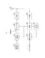
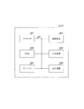
- FIG. 1 is a block diagram showing an example of the entire configuration of the radio base station 10 according to the present embodiment.
- the radio base station 10 includes a scheduler 101, a transmission signal generation unit 102, an encoding / modulation unit 103, a mapping unit 104, a transmission unit 105, an antenna 106, a reception unit 107, a control unit 108, and a channel.
- An estimation unit 109 and a demodulation / decoding unit 110 are included.
- the radio base station 10 may have a configuration of MU-MIMO (Multi-User Multiple-Input Multiple-Output) that communicates simultaneously with a plurality of user terminals 20.
- MU-MIMO Multi-User Multiple-Input Multiple-Output
- the wireless base station 10 may have a configuration of Single-User Multiple-Input Multiple-Output (SU-MIMO) that communicates with one user terminal 20.
- SU-MIMO Single-User Multiple-Input Multiple-Output
- the radio base station 10 may have both SU-MIMO and MU-MIMO configurations.
- the scheduler 101 performs scheduling (for example, resource allocation and port allocation) of DL signals (DL data signals, DL control signals, DMRS, etc.).
- the scheduler 101 also performs scheduling (for example, resource allocation and port allocation) of UL signals (UL data signal, UL control signal, DMRS, etc.).
- the scheduler 101 selects one of “Configuration type 1” and “Configuration type 2” as a configuration of a mapping pattern indicating resource elements to which DMRSs of DL signals are mapped.
- the scheduler 101 can determine the propagation path environment (for example, communication quality and frequency selectivity), and / or requirements (such as the moving speed of a terminal to support), and / or the performance of the radio base station 10 or the user terminal 20. Select one mapping pattern from Configuration type 1 or Configuration type 2 based on. Alternatively, one mapping pattern may be determined in advance.
- the scheduler 101 outputs scheduling information to the transmission signal generation unit 102 and the mapping unit 104. As described later, the scheduler 101 may regard the position at which the DMRS is mapped to the DL signal as an example of a control unit that hops to different frequencies at different times.
- the scheduler 101 performs, for example, MCS (Modulation and Coding Scheme) (coding rate, modulation scheme, etc.) of the DL data signal and the UL data signal based on the channel quality between the radio base station 10 and the user terminal 20.
- MCS Modulation and Coding Scheme
- the scheduler 101 outputs the information on the set MCS to the transmission signal generation unit 102 and the coding / modulation unit 103.
- MCS is not limited when the wireless base station 10 sets, and the user terminal 20 may set it.
- the radio base station 10 may receive MCS information from the user terminal 20 (not shown).
- the transmission signal generation unit 102 generates a transmission signal (including a DL data signal and a DL control signal).
- the DL control signal includes DCI including scheduling information (for example, setting information) output from the scheduler 101 or MCS information.
- the transmission signal generation unit 102 outputs the generated transmission signal to the coding / modulation unit 103.
- the encoding / modulation unit 103 performs encoding processing and modulation processing on the transmission signal input from the transmission signal generation unit 102 based on, for example, the MCS information input from the scheduler 101. Encoding / modulation section 103 outputs the modulated transmission signal to mapping section 104.
- the mapping unit 104 maps the transmission signal input from the encoding / modulation unit 103 to a radio resource (DL resource) based on scheduling information (for example, DL resource allocation and the like) input from the scheduler 101. Also, the mapping unit 104 maps the DMRS to a radio resource (DL resource) based on the scheduling information. Mapping section 104 outputs the DL signal mapped to the radio resource to transmitting section 105.
- DL resource for example, DL resource allocation and the like
- the transmission unit 105 performs transmission processing such as up-conversion and amplification on the DL signal input from the mapping unit 104, and transmits a radio frequency signal (DL signal) from the antenna 106.
- transmission processing such as up-conversion and amplification on the DL signal input from the mapping unit 104
- DL signal radio frequency signal
- the reception unit 107 performs reception processing such as amplification and down conversion on the radio frequency signal (UL signal) received by the antenna 106, and outputs the UL signal to the control unit 108.
- the UL signal may include a UL data signal, DMRS.
- the control unit 108 separates (demaps) the UL data signal and the DMRS from the UL signal input from the reception unit 107 based on the scheduling information (for example, UL resource allocation information and the like) input from the scheduler 101. ). Then, control section 108 outputs the UL data signal to demodulation / decoding section 110 and outputs DMRS to channel estimation section 109.
- the scheduling information for example, UL resource allocation information and the like
- Channel estimation section 109 performs channel estimation using the DMRS of the UL signal, and outputs a channel estimation value that is the estimation result to demodulation and decoding section 110.
- Demodulation / decoding section 110 performs demodulation and decoding processing on the UL data signal input from control section 108 based on the channel estimation value input from channel estimation section 109. Also, the demodulation / decoding unit 110 transfers the demodulated and decoded UL data signal to an application unit (not shown). The application unit performs processing on a layer higher than the physical layer or the MAC layer.
- the block including the scheduler 101, the transmission signal generation unit 102, the encoding / modulation unit 103, the mapping unit 104, and the transmission unit 105 may be regarded as an example of a wireless transmission apparatus provided in the wireless base station 10.
- the block including the receiving unit 107, the control unit 108, the channel estimation unit 109, and the demodulation / decoding unit 110 may be considered as an example of a wireless reception apparatus provided in the wireless base station 10.
- the block including the control unit 108, the channel estimation unit 109, and the demodulation / decoding unit 109 is a processing unit that receives and processes a UL signal using DMRS mapped in the time domain of the UL signal. You can think of it as an example of
- FIG. 2 is a block diagram showing an example of the entire configuration of the user terminal 20 according to the present embodiment.
- the user terminal 20 includes an antenna 201, a reception unit 202, a control unit 203, a channel estimation unit 204, a demodulation / decoding unit 205, a transmission signal generation unit 206, an encoding / modulation unit 207, and a mapping unit 208. And the transmission unit 209.
- the reception unit 202 performs reception processing such as amplification and down conversion on the radio frequency signal (DL signal) received by the antenna 201, and outputs the DL signal to the control unit 203.
- the DL signal may include a DL data signal, DMRS.
- the control unit 203 separates (demaps) the DL control signal and the DMRS from the DL signal input from the receiving unit 202. Then, the control unit 203 outputs the DL control signal to the demodulation / decoding unit 205, and outputs the DMRS to the channel estimation unit 204.
- the control unit 203 controls reception processing for the DL signal. Further, the control unit 203 separates (demaps) the DL data signal from the DL signal based on the scheduling information (for example, resource allocation information of the DL, etc.) input from the receiving unit 202, and demodulates the DL data signal. It is output to the decoding unit 205.
- the scheduling information for example, resource allocation information of the DL, etc.
- Channel estimation section 204 performs channel estimation using the DMRS separated from the DL signal, and outputs a channel estimation value that is the estimation result to demodulation and decoding section 205.
- the demodulation / decoding unit 205 demodulates the DL control signal input from the control unit 203. Also, the demodulation / decoding unit 205 performs a decoding process (for example, a blind detection process) on the DL control signal after demodulation. Demodulation / decoding section 205 outputs scheduling information (for example, DL / UL resource allocation information, etc.) for its own device obtained by decoding the DL control signal to control section 203 and mapping section 208, and DL data The MCS information on the signal is output to the encoding / modulation unit 207.
- a decoding process for example, a blind detection process
- Demodulation / decoding section 205 outputs scheduling information (for example, DL / UL resource allocation information, etc.) for its own device obtained by decoding the DL control signal to control section 203 and mapping section 208, and DL data
- scheduling information for example, DL / UL resource allocation information, etc.
- the demodulation / decoding unit 205 uses the channel estimation value input from the channel estimation unit 204 based on the MCS information for the DL data signal included in the DL control signal input from the control unit 203, The demodulation and decoding processing is performed on the DL data signal input from.
- the demodulation / decoding unit 205 transfers the demodulated and decoded DL data signal to an application unit (not shown).
- the application unit performs processing on a layer higher than the physical layer or the MAC layer.
- the transmission signal generation unit 206 generates a transmission signal (including a UL data signal or a UL control signal), and outputs the generated transmission signal to the encoding / modulation unit 207.
- the encoding / modulation unit 207 performs encoding processing and modulation processing on the transmission signal input from the transmission signal generation unit 206 based on, for example, the MCS information input from the demodulation / decoding unit 205. Coding / modulation section 207 outputs the modulated transmission signal to mapping section 208.
- the mapping unit 208 maps the transmission signal input from the encoding / modulation unit 207 to a radio resource (UL resource) based on the scheduling information (UL resource allocation) input from the demodulation / decoding unit 205. Also, the mapping unit 208 maps the DMRS to a radio resource (UL resource) based on the scheduling information.
- the mapping of the DMRS to the radio resource may be controlled by, for example, the control unit 203.
- the control unit 203 may regard the position at which the DMRS is mapped to the radio resource of the UL signal as an example of a control unit that hops to different frequencies at different times.
- the transmission unit 209 performs transmission processing such as up-conversion and amplification on the UL signal (for example, including UL data signal and DMRS) input from the mapping unit 208, and transmits the radio frequency signal (UL signal) to the antenna 201.
- UL signal for example, including UL data signal and DMRS
- the block including the transmission signal generation unit 206, the encoding / modulation unit 207, the mapping unit 208, and the transmission unit 209 may be considered as an example of a wireless transmission apparatus provided in the user terminal 20.
- the block including the reception unit 202, the control unit 203, the channel estimation unit 204, and the demodulation / decoding unit 205 may be considered as an example of a wireless reception apparatus provided in the user terminal 20.
- the block including the control unit 203, the channel estimation unit 204, and the demodulation / decoding unit 205 is a processing unit that receives and processes a DL signal using DMRS mapped to a radio resource of the DL signal. You can think of it as an example of
- a front-loaded DMRS may be used as an example of the DMRS.
- front-loaded DMRS may be described as "FL-DMRS”.
- the FL-DMRS is arranged forward in the time direction in a resource unit (or in a subframe) which is a resource allocation unit. By placing the FL-DMRS forward, in the wireless communication system, the processing time required for channel estimation and demodulation can be reduced.
- additional (additional) DMRS may be mapped to the FL-DMRS at a position distant in the time direction from the mapped position (for example, symbol) of the FL-DMRS. is there.
- additional DMRS may be described as “A-DMRS” for convenience.
- the DMRS may include only the FL-DMRS or both of the FL-DMRS and the A-DMRS.
- FL-DMRS and A-DMRS do not have to be distinguished from each other, they are simply referred to as "DMRS".
- mapping pattern of FL-DMRS two mapping patterns (Configuration type 1 & 2) are considered.
- two mapping patterns will be described using FIGS. 3A and 3B, respectively.
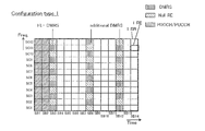
- FIG. 3A is a diagram illustrating an example of a first mapping pattern of the DMRS according to an embodiment.
- FIG. 3A shows an example of a DMRS mapping pattern in the case of focusing on one port (for example, port # 0 or port # 1 in Configuration type 1).
- the mapping pattern illustrated in FIG. 3A indicates the mapping position of DMRS in a resource unit (RU: Resource Unit), which is an example of a resource allocation unit.
- RU Resource Unit
- the RU may be referred to as a slot, a resource block (RB), a resource block pair, or the like.
- One resource block has, for example, a configuration in which 168 resource elements (RE: Resource Element) are aligned in the time direction and 14 in the frequency direction.
- RE resource elements
- One RE is a radio resource area defined by one symbol and one subcarrier. That is, one resource block is composed of 14 symbols and 12 subcarriers.
- the “slot” may be divided into “minislots” in the time direction.
- the “minislot” may be configured by, for example, the number of symbols ranging from 1 symbol to 14 symbols.
- one slot may be considered to correspond to an example of “unit time” in a radio link signal (which may be either a DL signal or a UL signal).
- the “unit time of the wireless link signal” is not limited to “one slot”, and may be a period including the number of symbols set appropriately.
- the period of one hop area described later with reference to FIGS. 7 to 9 may correspond to “a unit time of a wireless link signal”.
- a control channel for example, PDCCH or PUCCH
- PDCCH Physical Downlink Control Channel
- SB1 and SB2 the first two symbols
- the number of symbols in the control channel is not limited to 2 symbols, and may be 3 symbols.
- the control channel may be arranged in any of the first symbol (SB1) to the third symbol (SB3) of one slot.
- a plurality of DMRSs may be distributed in the frequency direction.
- DMRSs FL-DMRSs and / or A-DMRSs
- IFDM is an abbreviation of “Interleaved Frequency Division Multiplexing”.
- a data signal (PDSCH or PUSCH) may be allocated to REs in which DMRSs from the third symbol to the 14th symbol are not allocated.
- An RE for which DMRS and other signals are not arranged when focusing on one port may be referred to as “Null RE”.
- CSI-RS is an abbreviation of "Channel State Information-Reference Signal”.
- the FL-DMRS may be placed in the symbol immediately after the symbol in which the control channel is placed in the time direction, for example, the third symbol (SB3) in one slot. .
- the arrangement position of the FL-DMRS in the time direction is not limited to the third symbol (SB3).
- the FL-DMRS may be mapped to the fourth symbol (SB4) or the fifth symbol (SB5).
- the DMRS may be placed at the beginning of the symbol to which the PUSCH is mapped.
- the number of symbols in which the FL-DMRSs are arranged is not limited to one symbol.
- FL-DMRSs may be arranged in two symbols in one slot.
- the FL-DMRS may be arranged in the third symbol (SB3) and the fourth symbol (SB4) of one slot.
- the A-DMRS may be arranged in a symbol spaced apart in the time direction from the symbol in which the FL-DMRS is arranged in one slot.
- A-DMRSs When A-DMRSs are allocated to one symbol in one slot, A-DMRSs may be allocated to the 12th symbol (SB12) as shown in FIG. 3A, for example. When A-DMRSs are arranged in two symbols in one slot, A-DMRSs may be arranged, for example, in the eighth symbol (SB8) and the twelfth symbol (SB12) (for example, see FIG. 5A described later) . When A-DMRSs are allocated to three symbols in one slot, A-DMRSs may be allocated to, for example, the sixth symbol (SB6), the ninth symbol (SB9), and the twelfth symbol (SB12).
- the A-DMRSs may be arranged in the frequency direction at the same density as the arrangement density in the frequency direction of the FL-DMRSs.
- A-DMRSs may be arranged in the frequency direction in the same pattern as the arrangement pattern of FL-DMRSs in the frequency direction, as shown in FIG. 3A.
- FIG. 3B is a diagram showing an example of a second mapping pattern of DMRS in the present embodiment.
- FIG. 3B shows an example of a DMRS mapping pattern in the case of focusing on one port (for example, port # 0 or port # 1 in configuration type 1).
- a control channel for example, PDCCH or PUCCH
- PDCCH Physical Downlink Control Channel
- SB1 and SB2 the first two symbols
- the number of symbols in the control channel is not limited to 2 symbols, and may be 3 symbols.
- the control channel may be arranged in any of the first symbol (SB1) to the third symbol (SB3) of one slot.
- a plurality of DMRSs may be distributed in the frequency direction.
- DMRSs (FL-DMRSs and / or A-DMRSs) of the same port may be spaced by 4 subcarriers.
- the interval at which DMRSs (FL-DMRSs and / or A-DMRSs) of the same port are arranged in the frequency direction is not limited to four subcarriers.
- a data signal (PDSCH or PUSCH) may be allocated to REs in which DMRSs from the third symbol to the 14th symbol are not allocated.
- An RE for which DMRS and other signals are not arranged when focusing on one port may be referred to as “Null RE”.
- DMRS when focusing on one port, DMRS, a signal of a data channel (for example, PDSCH or PUSCH), or DMRS when focusing on another port May be placed at the position of “Null RE” (eg, CSI-RS).
- the FL-DMRS may be arranged in the symbol immediately after the symbol in which the control channel is arranged in the time direction, for example, the third symbol (SB3) in one slot.
- the arrangement position of the FL-DMRS in the time direction is not limited to the third symbol (SB3).
- the FL-DMRS may be mapped to the fourth symbol (SB4) or the fifth symbol (SB5).
- the DMRS may be placed at the beginning of the symbol to which the PUSCH is mapped.
- the number of symbols in which the FL-DMRSs are arranged is not limited to one symbol.
- FL-DMRSs may be arranged in two symbols in one slot.
- the FL-DMRS may be arranged in the third symbol (SB3) and the fourth symbol (SB4) of one slot.
- the A-DMRS may be arranged in a symbol spaced apart in the time direction from the symbol in which the FL-DMRS is arranged in one slot.
- A-DMRSs When A-DMRSs are allocated to one symbol in one slot, A-DMRSs may be allocated to the 12th symbol (SB12) as shown in FIG. 3B, for example. When A-DMRSs are arranged in two symbols in one slot, A-DMRSs may be arranged, for example, in the eighth symbol (SB8) and the twelfth symbol (SB12) (for example, see FIG. 5B described later) . When A-DMRSs are allocated to three symbols in one slot, A-DMRSs may be allocated to, for example, the sixth symbol (SB6), the ninth symbol (SB9), and the twelfth symbol (SB12).
- the A-DMRSs may be arranged in the frequency direction at the same density as the arrangement density in the frequency direction of the FL-DMRSs.
- A-DMRSs may be arranged in the frequency direction in the same pattern as the arrangement pattern of FL-DMRSs in the frequency direction, as shown in FIG. 3B.
- mapping pattern regarding DMRS mentioned above is an example, and this invention is not limited to this.
- DMRS collision If multiple cells use the same mapping pattern illustrated in FIG. 3A or 3B for the same port number, DMRS collisions occur between the cells. For example, in the situation where the same Configuration type is set and the same port number is used among a plurality of cells, the same mapping pattern may result. When a collision between DMRSs occurs between cells, the channel estimation accuracy using the DMRS on the receiving side of the radio signal is degraded, and the reception characteristic of the radio signal is degraded.
- the DMRS mapping position is changed to different frequencies at different times (for convenience, this may be referred to as “frequency hopping”), thereby reducing the probability of DMRS collisions between different cells. Do.
- the frequency hopping of DMRS can prevent the same DMRS mapping pattern from being used between different cells. Thereby, it is possible to achieve randomization of interference between DMRSs. Therefore, a decrease in channel estimation accuracy using DMRS can be suppressed, and a decrease in reception characteristics of radio signals can be suppressed.
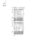
- FIGS. 4A and 4B are diagrams showing a first example of DMRS frequency hopping according to an embodiment.
- FIG. 4A shows an example of frequency hopping of DMRS based on the first mapping pattern (Configuration type 1).
- FIG. 4B shows an example of frequency hopping of DMRS based on the second mapping pattern (Configuration type 2).
- control channels eg, PDCCH or PUCCH
- pattern of FL-DMRS may be the same as those in FIGS. 3A and 3B, respectively.
- A-DMRSs are mapped (frequency hopping) to different frequencies as compared with FIGS. 3A and 3B.
- the arrangement pattern of A-DMRSs arranged in the 12th symbol (SB12) in the frequency direction of the A-DMRSs corresponds to the arrangement direction of one subcarrier by the amount of Corresponds to the shifted pattern.
- the arrangement pattern of the A-DMRSs arranged in the SB 12 in the frequency direction corresponds to a pattern shifted in the frequency direction by two subcarriers as compared to FIG. 3B.
- FIG. 4A when the arrangement pattern in the frequency direction of A-DMRS is frequency-shifted cyclically by two or more even-numbered subcarriers, the arrangement pattern in the frequency direction becomes the same as the pattern of FIG. 3A. Therefore, in the case of FIG. 4A, there are two arrangement patterns (two patterns) as A-DMRS arrangement patterns.
- the frequency shift amount of the arrangement pattern of A-DMRS is one subcarrier
- the arrangement pattern in the frequency direction is six ways (six patterns), and three cases for two subcarriers. 3 patterns).
- the frequency shift amount is not limited to these.
- 4A and 4B is an example in which frequency hopping of A-DMRS is performed among FL-DMRS and A-DMRS, but conversely, frequency hopping of FL-DMRS may be performed.
- both FL-DMRS and A-DMRS may be frequency hopping individually.
- FIGS. 5A and 5B illustrate a second example of DMRS frequency hopping according to an embodiment.
- FIG. 5A shows an example of DMRS frequency hopping based on a first mapping pattern (Configuration type 1)
- FIG. 5B shows a DMRS frequency based on a second mapping pattern (Configuration type 2).
- An example of hopping is shown.
- a plurality of A-DMRSs may be distributed in the time direction in one slot.
- an A-DMRS may be arranged for each of the eighth symbol (SB8) and the twelfth symbol (SB12) of one slot.
- the arrangement of control channels (for example, PDCCH or PUCCH) and the arrangement of FL-DMRSs may be the same as those in FIGS. 3A and 3B, respectively.
- the plurality of A-DMRSs may be individually frequency hopping.
- the first A-DMRS may be frequency hopping.
- the second A-DMRS located at SB 12 may be frequency hopped.
- the frequency hopping amount may be the same or different for the first A-DMRS and the second A-DMRS.
- a different mapping pattern may be applied in the frequency direction for each of a plurality of A-DMRSs, or the same mapping pattern may be applied in the frequency direction for all A-DMRSs.
- both the first A-DMRS disposed in SB 8 and the second A-DMRS disposed in SB 12 may be frequency hopping.
- the frequency hopping amount may be the same as or different between the first A-DMRS placed in SB 8 and the second A-DMRS placed in SB 12.
- FIG. 5B shows an example in which the first A-DMRS performs frequency hopping by two subcarriers, and the second A-DMRS disposed in the SB 12 performs frequency hopping by four subcarriers.
- first and second A-DMRSs may be frequency hopping.
- frequency hopping may be performed individually also in a case where, for example, A-DMRSs are arranged in each of SB6, SB9 and SB12.
- the frequency hopping amount may be the same for three symbols of A-DMRS, or may be different for all or part of three symbols of A-DMRS.
- FIGS. 5A and 5B are examples in which frequency hopping of the FL-DMRS is not performed, the frequency hopping of the FL-DMRS may be performed.
- the A-DMRS may not perform frequency hopping or may perform frequency hopping.
- the same A-DMRS arrangement among different cells It can prevent the pattern from being used continuously. This makes it possible to randomize the interference between A-DMRSs. Therefore, it is possible to suppress a decrease in channel estimation accuracy using A-DMRS, and to suppress a decrease in reception characteristics of a radio signal.
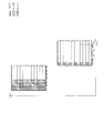
- FIG. 6 is a diagram showing a third example of DMRS frequency hopping according to an embodiment.
- the third example is an example in which the mapping position in the frequency direction of the DMRS is changed on a slot basis.
- both FL-DMRS and A-DMRS are equivalent to one subcarrier.
- a frequency hopping constellation pattern may be applied.
- the FL-DMRS may not be frequency hopping, as in FIG. 4A. Also, in the first slot, one of the FL-DMRS and the A-DMRS may be frequency hopping as described in FIG. 4A.
- the arrangement pattern of DMRSs (FL-DMRSs and / or A-DMRSs) in the frequency direction may be different in one or both of the slots and in the slots.
- the DMRS arrangement pattern illustrated in FIG. 5A may be applied, and in the second slot, the DMRS arrangement pattern illustrated in FIG. 5B may be applied.
- any two of the DMRS arrangement patterns illustrated in FIGS. 4A, 4B, 5A, and 5B may be selectively applied to two slots.
- the DMRS arrangement pattern illustrated in FIG. 4A or 4B may be applied, and in the second slot, the DMRS arrangement pattern illustrated in FIG. 5A or 5B may be applied.
- the DMRS arrangement pattern illustrated in FIG. 5A or 5B is applied, and in the second slot, the DMRS arrangement pattern illustrated in FIG. 4A or 4B is applied. It is also good.
- the arrangement pattern of FIG. 4A, FIG. 4B, FIG. 5A and / or FIG. 5B and other arrangement patterns may be selectively applied in units of one or more slots.
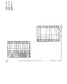
- FIGS. 7 to 9 illustrate a fourth example of DMRS frequency hopping according to an embodiment.
- the fourth example is a frequency hopping example of DMRS when frequency hopping in a slot is applied in UL.
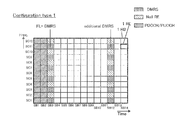
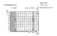
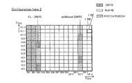
- FIGS. 7, 8 and 9 show frequency hopping examples of DMRS based on the first mapping pattern (Configuration type 1).
- one slot may be divided into a first hop area (SB1 to SB7) and a second hop area (SB8 to SB14) in the time direction.
- the second hop region is hopped to a lower frequency band than the first hop region. Note that the second hop region may hop to a frequency band higher than the first hop region.
- a control channel for example, PUCCH
- PUCCH may be allocated to REs of the first two symbols (SB1 and SB2) of the first hop region.
- the number of symbols of the control channel is not limited to two symbols, and may be three symbols.
- the control channel may be arranged in any of the first symbol (SB1) to the third symbol (SB3) of one slot.
- the DMRS may be disposed at the third symbol (SB3) of the first hop region.
- the arrangement position of the DMRS in the time direction is not limited to the third symbol (SB3).
- the DMRS may be mapped to the fourth symbol (SB4) or the fifth symbol (SB5).
- the number of symbols in which the DMRS in the first hop region is arranged is not limited to one symbol.
- DMRSs may be arranged in two symbols in the first hop region.
- DMRSs may be arranged at the third symbol (SB3) and the fourth symbol (SB4).
- the DMRS may be placed at the beginning (eg, SB8) of the symbol to which the PUSCH is mapped.
- the mapping positions of DMRSs may be hopped to different frequencies in the first hop area and the second hop area.
- the DMRS mapped to the leading symbol (SB8) of the second hop area may be frequency hopping.
- the DMRSs mapped to the leading symbol (SB 8) of the second hop area may frequency hop the DMRSs arranged in the third symbol of the first hop area without hopping.
- DMRS mapping positions may be frequency hopping individually for both the first hop region and the second hop region.
- a plurality of DMRSs may be distributed and arranged in the time direction in the first hop region and / or the second hop region.
- each of the first hop area and the second hop area is regarded as a "slot", and any one of DMRS arrangement patterns described in FIGS. 4A and 5A is selectively applied to any hop area. It is also good.
- the DMRS may be arranged in the third symbol (SB3) and the end symbol (the seventh symbol (SB7)) of the first hop region.
- the DMRS placed in the last symbol of the first hop area may be considered to correspond to “A-DMRS”.
- DMRSs of three symbols may be distributed and arranged in the time direction.
- DMRSs may be allocated to the leading symbol (SB8) and the trailing symbol (SB14).
- SB8 leading symbol
- SB14 trailing symbol
- DMRSs of three symbols may be distributed and arranged in the time direction.
- a plurality of DMRSs are disposed in each of the first hop region and the second hop region, but a plurality of DMRSs are disposed in only one of the first hop region and the second hop region.
- the DMRS may not be arranged at the end symbol (SB7) of the first hop area.
- the DMRS may be arranged only in one of the leading symbol (SB8) and the end symbol (SB14) of the second hop area, and the DMRS may not be arranged in the other.
- the DMRS mapping positions may be hopped to different frequencies in the first hop area and the second hop area.
- the DMRS mapped to the SB 14 may be frequency hopping.
- the DMRS mapped to SB8 may be frequency hopping.
- mapping positions may be hopped to relatively different frequencies.
- different DMRS mapping patterns may be applied to the first hop area and the second hop area.
- each of the first hop area and the second hop area in FIGS. 8 and 9 is regarded as a “slot”, and any one of the DMRS arrangement patterns described in FIGS. 4B and 5B can be selectively selected. It may be applied to the hop area.
- the number of hop areas is not limited to two. Three or more hop regions may be set in the time direction. When three or more hop areas are set, frequency hopping (pattern) exemplified in FIG. 7 or 8 may be applied to part or all of each hop area.
- the plurality of hop areas are not limited to the case where the same number of symbols are included, respectively, and may be configured by different numbers of symbols.
- the number of hop areas is 2, the first hop area may be configured by 10 symbols, and the second hop area may be configured by 4 symbols.
- the fourth example of DMRS frequency hopping described above it can be suppressed that the same DMRS arrangement pattern is continuously used among user terminals 20 of different cells with respect to the UL signal. Thereby, it is possible to achieve randomization of interference between DMRSs. Therefore, in the radio base station 10 which is the reception side of the UL signal, it is possible to suppress the decrease in channel estimation accuracy using the DMRS, and it is possible to suppress the decrease in the reception characteristic of the UL signal.
- the frequency hopping (pattern) of DMRS for the DL signal and the UL signal may be set by the radio base station 10, for example.
- the arrangement position of the DMRS with respect to the DL signal may be determined based on the determined frequency hopping pattern, and the DMRS may be mapped to the arrangement position.
- the user terminal 20 receives notification of information on the frequency hopping (pattern) determined in the radio base station 10, specifies the DMRS arrangement position, and receives the DL signal or maps the DMRS to the UL signal. I do.
- Notification of information on the frequency hopping (pattern) of DMRS enables flexible change of the arrangement position of DMRS as needed.
- the mapping patterns for a plurality of cells are determined in the upper layer and set in the corresponding radio base station 10. Good.
- Notification of information on DMRS frequency hopping The “notification” of the information on the frequency hopping (pattern) of the DMRS described above may be implicitly performed or may be explicitly performed in association with some information.
- Cell ID, user index, slot index, and symbol index are mentioned as a non-limiting example of the information with which information on frequency hopping (pattern) of DMRS is associated in implicit notification.
- Information on DMRS frequency hopping may be associated with any one or more of the cell ID, the user index, the slot index, and the symbol index. The association allows the frequency hopping (pattern) of the DMRS to be identified implicitly, thereby reducing signaling for notification.
- Radio Resource Control RRC
- MAC layer signaling and / or physical (PHY) layer signaling may be used, or hybrid indication combining the above (a) and (b) may be used.
- DCI of PDCCH may be used, and DCI may indicate information on frequency hopping (pattern) of DMRS.
- information on frequency hopping (pattern) of DMRS may be associated with information indicating presence or absence of sequence hopping.
- information indicating the frequency hopping “absent” and “presence” of the DMRS may be associated with information indicating the sequence hopping “present” and “absent”, respectively.
- information on frequency hopping (pattern) of DMRS may be notified by higher layer signaling.
- information on frequency hopping (pattern) of DMRS may be identified by a combination of a plurality of pieces of information exemplified above.
- the size (number of symbols) in the time direction of the control channel is not limited to 2, and may be 0, 1, or 3, for example. Also, the PDCCH signal may be inserted into part of the symbol.
- the arrangement position of DMRS is not limited to the third symbol of one slot.
- the arrangement position of DMRS may be the fourth symbol of one slot, the head symbol of a data channel (for example, PUSCH), or the second symbol of PUSCH.
- the number of symbols in which DMRSs are arranged is not limited to one.
- the DMRS may be arranged across two symbols of the third symbol and the fourth symbol of one slot, or may be arranged across two symbols of the fourth symbol and the fifth symbol of one slot.
- the PDSCH may be referred to as a downlink data channel.
- the PUSCH may be referred to as an upstream data channel.
- the PDCCH may be referred to as a downlink control channel.
- the PUCCH may be referred to as an uplink control channel.
- each functional block may be realized by one physically and / or logically coupled device, or directly and / or indirectly two or more physically and / or logically separated devices. It may be connected by (for example, wired and / or wireless) and realized by the plurality of devices.
- the wireless base station 10, the user terminal 20, and the like in one embodiment of the present invention may function as a computer that performs the processing of the wireless communication method of the present invention.
- FIG. 10 is a diagram showing an example of the hardware configuration of the radio base station 10 and the user terminal 20 according to an embodiment.
- the above-described wireless base station 10 and user terminal 20 may be physically configured as a computer device including a processor 1001, a memory 1002, a storage 1003, a communication device 1004, an input device 1005, an output device 1006, a bus 1007 and the like. Good.
- the term “device” can be read as a circuit, a device, a unit, or the like.
- the hardware configuration of the radio base station 10 and the user terminal 20 may be configured to include one or more of the devices illustrated in FIG. 10 or may be configured without including some devices.
- processor 1001 may be implemented by one or more chips.
- Each function in the radio base station 10 and the user terminal 20 performs a calculation by causing the processor 1001 to read predetermined software (program) on hardware such as the processor 1001 and the memory 1002, and performs communication by the communication device 1004 or This is realized by controlling reading and / or writing of data in the memory 1002 and the storage 1003.
- the processor 1001 operates, for example, an operating system to control the entire computer.
- the processor 1001 may be configured by a central processing unit (CPU: Central Processing Unit) including an interface with a peripheral device, a control device, an arithmetic device, a register, and the like.
- CPU Central Processing Unit
- the above-described scheduler 101, transmission signal generation units 102 and 206, coding / modulation units 103 and 207, mapping units 104 and 208, control units 108 and 203, channel estimation units 109 and 204, demodulation / decoding units 110 and 205 And the like may be realized by the processor 1001.
- the processor 1001 reads a program (program code), a software module or data from the storage 1003 and / or the communication device 1004 to the memory 1002, and executes various processing according to these.
- a program a program that causes a computer to execute at least a part of the operations described in the above embodiments is used.
- the scheduler 101 of the radio base station 10 may be realized by a control program stored in the memory 1002 and operated by the processor 1001, or may be realized similarly for other functional blocks.
- the various processes described above have been described to be executed by one processor 1001, but may be executed simultaneously or sequentially by two or more processors 1001.
- the processor 1001 may be implemented by one or more chips.
- the program may be transmitted from the network via a telecommunication line.
- the memory 1002 is a computer readable recording medium, and includes, for example, at least one of a ROM (Read Only Memory), an EPROM (Erasable Programmable ROM), an EEPROM (Electrically Erasable Programmable ROM), and a RAM (Random Access Memory). It may be done.
- the memory 1002 may be called a register, a cache, a main memory (main storage device) or the like.
- the memory 1002 can store a program (program code), a software module, and the like that can be executed to implement the wireless communication method according to an embodiment of the present invention.
- the storage 1003 is a computer readable recording medium, and for example, an optical disc such as a CD-ROM (Compact Disc ROM), a hard disc drive, a flexible disc, a magneto-optical disc (eg, a compact disc, a digital versatile disc, a Blu-ray A (registered trademark) disk, a smart card, a flash memory (for example, a card, a stick, a key drive), a floppy (registered trademark) disk, a magnetic strip, and the like may be used.
- the storage 1003 may be called an auxiliary storage device.
- the above-mentioned storage medium may be, for example, a database including the memory 1002 and / or the storage 1003, a server or any other suitable medium.
- the communication device 1004 is hardware (transmission / reception device) for performing communication between computers via a wired and / or wireless network, and is also called, for example, a network device, a network controller, a network card, a communication module, or the like.
- a network device for example, a network controller, a network card, a communication module, or the like.
- the above-described transmission units 105 and 209, antennas 106 and 201, and reception units 107 and 202 may be realized by the communication device 1004.
- the input device 1005 is an input device (for example, a keyboard, a mouse, a microphone, a switch, a button, a sensor, and the like) that receives an input from the outside.
- the output device 1006 is an output device (for example, a display, a speaker, an LED lamp, etc.) that performs output to the outside.
- the input device 1005 and the output device 1006 may be integrated (for example, a touch panel).
- each device such as the processor 1001 and the memory 1002 is connected by a bus 1007 for communicating information.
- the bus 1007 may be configured by a single bus or may be configured by different buses among the devices.
- radio base station 10 and the user terminal 20 may be microprocessors, digital signal processors (DSPs), application specific integrated circuits (ASICs), programmable logic devices (PLDs), field programmable gate arrays (FPGAs), etc. It may be configured to include hardware, and part or all of each functional block may be realized by the hardware. For example, processor 1001 may be implemented in at least one of these hardware.
- DSPs digital signal processors
- ASICs application specific integrated circuits
- PLDs programmable logic devices
- FPGAs field programmable gate arrays
- notification of information is not limited to the aspect / embodiment described herein, and may be performed by other methods.
- notification of information may be physical layer signaling (for example, Downlink Control Information (DCI), Uplink Control Information (UCI)), upper layer signaling (for example, Radio Resource Control (RRC) signaling, Medium Access Control (MAC) signaling, It may be implemented by broadcast information (MIB (Master Information Block), SIB (System Information Block)), other signals, or a combination thereof.
- RRC signaling may be referred to as an RRC message, and may be, for example, an RRC connection setup (RRC Connection Setup) message, an RRC connection reconfiguration (RRC Connection Reconfiguration) message, or the like.
- Each aspect / embodiment described in the present specification is LTE (Long Term Evolution), LTE-A (LTE-Advanced), SUPER 3G, IMT-Advanced, 4G, 5G, FRA (Future Radio Access), W-CDMA (Registered trademark), GSM (registered trademark), CDMA2000, UMB (Ultra Mobile Broadband), IEEE 802.11 (Wi-Fi), IEEE 802.16 (WiMAX), IEEE 802.20, UWB (Ultra-Wide Band),
- the present invention may be applied to a system utilizing Bluetooth (registered trademark), other appropriate systems, and / or an advanced next-generation system based on these.
- the specific operation supposed to be performed by the base station (radio base station) in this specification may be performed by the upper node in some cases.
- the various operations performed for communication with the terminals may be performed by the base station and / or other network nodes other than the base station (for example, it is clear that it may be performed by MME (Mobility Management Entity) or S-GW (Serving Gateway), but not limited thereto.
- MME Mobility Management Entity
- S-GW Serving Gateway
- Information, signals, etc. may be output from the upper layer (or lower layer) to the lower layer (or upper layer). Input and output may be performed via a plurality of network nodes.
- the input / output information may be stored in a specific place (for example, a memory), or may be managed by a management table. Information to be input or output may be overwritten, updated or added. The output information may be deleted. The input information or the like may be transmitted to another device.
- the determination may be performed by a value (0 or 1) represented by one bit, may be performed by a boolean value (Boolean: true or false), or may be compared with a numerical value (for example, a predetermined value). Comparison with the value).
- Software may be called software, firmware, middleware, microcode, hardware description language, or any other name, and may be instructions, instruction sets, codes, code segments, program codes, programs, subprograms, software modules. Should be interpreted broadly to mean applications, software applications, software packages, routines, subroutines, objects, executables, threads of execution, procedures, functions, etc.
- software, instructions, etc. may be sent and received via a transmission medium.
- software may use a wireline technology such as coaxial cable, fiber optic cable, twisted pair and digital subscriber line (DSL) and / or a website, server or other using wireless technology such as infrared, radio and microwave When transmitted from a remote source, these wired and / or wireless technologies are included within the definition of transmission medium.
- wireline technology such as coaxial cable, fiber optic cable, twisted pair and digital subscriber line (DSL) and / or a website, server or other using wireless technology such as infrared, radio and microwave
- Information, signal The information, signals, etc. described herein may be represented using any of a variety of different techniques.
- data, instructions, commands, information, signals, bits, symbols, chips etc may be voltage, current, electromagnetic waves, magnetic fields or particles, optical fields or photons, or any of these May be represented by a combination of
- the channels and / or symbols may be signals.
- the signal may be a message.
- the component carrier (CC) may be called a carrier frequency, a cell or the like.
- radio resources may be indexed.
- a base station can accommodate one or more (e.g., three) cells (also called sectors). If the base station accommodates multiple cells, the entire coverage area of the base station can be divided into multiple smaller areas, each smaller area being a base station subsystem (eg, a small base station RRH for indoor use: Remote Communication service can also be provided by Radio Head.
- the terms "cell” or “sector” refer to a base station that provides communication services in this coverage and / or part or all of the coverage area of a base station subsystem.
- the terms “base station”, “eNB”, “gNB”, “cell” and “sector” may be used interchangeably herein.
- a base station may be called in terms of a fixed station (Node station), NodeB, eNodeB (eNB), gNodeB (gNB) access point, access point, femtocell, small cell, and the like.
- the user terminal may be a mobile station, a subscriber station, a mobile unit, a subscriber unit, a wireless unit, a remote unit, a mobile device, a wireless device, a wireless communication device, a remote communication device, a mobile subscriber station, an access terminal, a mobile terminal by a person skilled in the art It may also be called a terminal, a wireless terminal, a remote terminal, a handset, a user agent, a mobile client, a client, a UE (User Equipment), or some other suitable term.
- determining may encompass a wide variety of operations.
- “Judgment”, “decision” are, for example, judging, calculating, calculating, processing, processing, deriving, investigating, looking up (for example, a table) (Searching in a database or another data structure), ascertaining may be regarded as “decision”, “decision”, etc.
- “determination” and “determination” are receiving (e.g. receiving information), transmitting (e.g. transmitting information), input (input), output (output), access (accessing) (for example, accessing data in a memory) may be regarded as “judged” or “decided”.
- connection means any direct or indirect connection or coupling between two or more elements, It can include the presence of one or more intermediate elements between two elements that are “connected” or “coupled”.
- the coupling or connection between elements may be physical, logical or a combination thereof.
- the two elements are by using one or more wires, cables and / or printed electrical connections, and radio frequency as some non-limiting and non-exclusive examples. It can be considered “connected” or “coupled” to one another by using electromagnetic energy such as electromagnetic energy having wavelengths in the region, microwave region and light (both visible and invisible) regions.
- the reference signal may be abbreviated as RS (Reference Signal), and may be called a pilot (Pilot) according to the applied standard.
- RS Reference Signal
- DMRS may be another corresponding name, such as demodulation RS or DM-RS.
- the phrase “based on” does not mean “based only on,” unless expressly stated otherwise. In other words, the phrase “based on” means both “based only on” and “based at least on.”
- a radio frame may be comprised of one or more frames in the time domain. Each frame or frames in the time domain may be referred to as subframes, time units, and so on.
- a subframe may be further comprised of one or more slots in the time domain.
- the slot may be further configured by one or more symbols (such as Orthogonal Frequency Division Multiplexing (OFDM) symbols, Single Carrier-Frequency Division Multiple Access (SC-FDMA) symbols, etc.) in the time domain.
- OFDM Orthogonal Frequency Division Multiplexing
- SC-FDMA Single Carrier-Frequency Division Multiple Access
- a radio frame, a subframe, a slot, a minislot, and a symbol all represent time units when transmitting a signal.
- a radio frame, a subframe, a slot, a minislot, and a symbol may be another name corresponding to each.
- the base station performs scheduling to assign radio resources (frequency bandwidth usable in each mobile station, transmission power, etc.) to each mobile station.
- the minimum time unit of scheduling may be called a TTI (Transmission Time Interval).
- one subframe may be called a TTI
- a plurality of consecutive subframes may be called a TTI
- one slot may be called a TTI
- one minislot may be called a TTI
- a resource unit is a resource allocation unit in time domain and frequency domain, and may include one or more consecutive subcarriers in frequency domain.
- the time domain of the resource unit may include one or more symbols, and may be one slot, one minislot, one subframe, or one TTI long.
- One TTI and one subframe may be configured of one or more resource units, respectively.
- resource units may be referred to as resource blocks (RBs), physical resource blocks (PRBs: physical RBs), PRB pairs, RB pairs, scheduling units, frequency units, and subbands.
- a resource unit may be configured of one or more REs.
- 1 RE may be a resource of a unit smaller than the resource unit serving as a resource allocation unit (for example, the smallest resource unit), and is not limited to the name of RE.
- the above-described radio frame structure is merely an example, and the number of subframes included in the radio frame, the number of slots included in the subframe, the number of minislots included in the subframe, and the symbols and resource blocks included in the slots.
- the number and the number of subcarriers included in the resource block can be variously changed.
- notification of predetermined information is not limited to what is explicitly performed, but is performed by implicit (for example, not notifying of the predetermined information) It is also good.
- One aspect of the present invention is useful for a mobile communication system.
Priority Applications (3)
| Application Number | Priority Date | Filing Date | Title |
|---|---|---|---|
| US16/764,222 US20200280411A1 (en) | 2017-11-17 | 2017-11-17 | Radio transmission apparatus and radio reception apparatus |
| PCT/JP2017/041568 WO2019097700A1 (ja) | 2017-11-17 | 2017-11-17 | 無線送信装置および無線受信装置 |
| EP17932193.0A EP3713103A4 (de) | 2017-11-17 | 2017-11-17 | Drahtlose übertragungsvorrichtung und drahtlose empfangsvorrichtung |
Applications Claiming Priority (1)
| Application Number | Priority Date | Filing Date | Title |
|---|---|---|---|
| PCT/JP2017/041568 WO2019097700A1 (ja) | 2017-11-17 | 2017-11-17 | 無線送信装置および無線受信装置 |
Publications (1)
| Publication Number | Publication Date |
|---|---|
| WO2019097700A1 true WO2019097700A1 (ja) | 2019-05-23 |
Family
ID=66539480
Family Applications (1)
| Application Number | Title | Priority Date | Filing Date |
|---|---|---|---|
| PCT/JP2017/041568 WO2019097700A1 (ja) | 2017-11-17 | 2017-11-17 | 無線送信装置および無線受信装置 |
Country Status (3)
| Country | Link |
|---|---|
| US (1) | US20200280411A1 (de) |
| EP (1) | EP3713103A4 (de) |
| WO (1) | WO2019097700A1 (de) |
Citations (1)
| Publication number | Priority date | Publication date | Assignee | Title |
|---|---|---|---|---|
| JP2009171025A (ja) * | 2008-01-11 | 2009-07-30 | Panasonic Corp | 移動局装置及び基地局装置、並びに無線通信システム |
Family Cites Families (2)
| Publication number | Priority date | Publication date | Assignee | Title |
|---|---|---|---|---|
| JP2013017016A (ja) * | 2011-07-04 | 2013-01-24 | Sharp Corp | 基地局装置、移動局装置、通信システムおよび通信方法 |
| JP6220049B2 (ja) * | 2013-04-01 | 2017-10-25 | パナソニック インテレクチュアル プロパティ コーポレーション オブ アメリカPanasonic Intellectual Property Corporation of America | 送信装置および制御信号配置方法 |
-
2017
- 2017-11-17 EP EP17932193.0A patent/EP3713103A4/de active Pending
- 2017-11-17 WO PCT/JP2017/041568 patent/WO2019097700A1/ja unknown
- 2017-11-17 US US16/764,222 patent/US20200280411A1/en not_active Abandoned
Patent Citations (1)
| Publication number | Priority date | Publication date | Assignee | Title |
|---|---|---|---|---|
| JP2009171025A (ja) * | 2008-01-11 | 2009-07-30 | Panasonic Corp | 移動局装置及び基地局装置、並びに無線通信システム |
Non-Patent Citations (6)
| Title |
|---|
| "3GPP TS 36.300", June 2016, article "Evolved Universal Terrestrial Radio Access (E-UTRA) and Evolved Universal Terrestrial Radio Access Network (E-UTRAN); Overall description; Stage 2 (Release 13" |
| "On DMRS design", 3 GPP TSG RAN WG1 MEETING #90BIS R1-1717946, vol. 5, 13 October 2017 (2017-10-13), XP051341130 * |
| "Remaining issues on DMRS design", 3GPP TSG RAN WG1 MEETING 90BIS R1-1718547, 13 October 2017 (2017-10-13), XP051341729 * |
| ERICSSON: "Remaining details on DMRS design", 3GPP TSG RAN WG1 MEETING 90BIS R1-1718448, 13 October 2017 (2017-10-13), XP051341630 * |
| QUALCOMMERICSSONPANASONICNTT DOCOMOZTECONVIDANOKIAASBSONYINTEL: "Way Forward On Frame Structure", R1-165575, May 2016 (2016-05-01) |
| See also references of EP3713103A4 * |
Also Published As
| Publication number | Publication date |
|---|---|
| EP3713103A1 (de) | 2020-09-23 |
| US20200280411A1 (en) | 2020-09-03 |
| EP3713103A4 (de) | 2021-07-07 |
Similar Documents
| Publication | Publication Date | Title |
|---|---|---|
| JP7054701B2 (ja) | 端末および通信方法 | |
| JP7470513B2 (ja) | 端末及び基地局 | |
| CN111386737B (zh) | 无线发送装置及无线接收装置 | |
| US11336382B2 (en) | Terminal, radio communication system, and radio communication method to reduce an increase in signaling overhead | |
| JP2022033190A (ja) | 端末、基地局及び無線通信方法 | |
| WO2019102531A1 (ja) | 無線送信装置および無線受信装置 | |
| JP2021101550A (ja) | 端末及び無線通信システム | |
| WO2019138562A1 (ja) | 無線通信装置 | |
| JP6995787B2 (ja) | 端末及び基地局 | |
| JP7195153B2 (ja) | ユーザ端末及び無線通信方法 | |
| WO2019097700A1 (ja) | 無線送信装置および無線受信装置 | |
| WO2018229956A1 (ja) | ユーザ端末及び無線通信方法 | |
| WO2018229957A1 (ja) | ユーザ端末及びチャネル推定方法 | |
| JP7053685B2 (ja) | ユーザ端末および無線通信方法 |
Legal Events
| Date | Code | Title | Description |
|---|---|---|---|
| 121 | Ep: the epo has been informed by wipo that ep was designated in this application |
Ref document number: 17932193 Country of ref document: EP Kind code of ref document: A1 |
|
| NENP | Non-entry into the national phase |
Ref country code: DE |
|
| ENP | Entry into the national phase |
Ref document number: 2017932193 Country of ref document: EP Effective date: 20200617 |
|
| NENP | Non-entry into the national phase |
Ref country code: JP |