WO2019097648A1 - Transport device - Google Patents
Transport device Download PDFInfo
- Publication number
- WO2019097648A1 WO2019097648A1 PCT/JP2017/041359 JP2017041359W WO2019097648A1 WO 2019097648 A1 WO2019097648 A1 WO 2019097648A1 JP 2017041359 W JP2017041359 W JP 2017041359W WO 2019097648 A1 WO2019097648 A1 WO 2019097648A1
- Authority
- WO
- WIPO (PCT)
- Prior art keywords
- articles
- lift
- bridge
- flat
- row
- Prior art date
Links
Images


Classifications
-
- B—PERFORMING OPERATIONS; TRANSPORTING
- B65—CONVEYING; PACKING; STORING; HANDLING THIN OR FILAMENTARY MATERIAL
- B65G—TRANSPORT OR STORAGE DEVICES, e.g. CONVEYORS FOR LOADING OR TIPPING, SHOP CONVEYOR SYSTEMS OR PNEUMATIC TUBE CONVEYORS
- B65G47/00—Article or material-handling devices associated with conveyors; Methods employing such devices
- B65G47/02—Devices for feeding articles or materials to conveyors
- B65G47/04—Devices for feeding articles or materials to conveyors for feeding articles
- B65G47/06—Devices for feeding articles or materials to conveyors for feeding articles from a single group of articles arranged in orderly pattern, e.g. workpieces in magazines
- B65G47/08—Devices for feeding articles or materials to conveyors for feeding articles from a single group of articles arranged in orderly pattern, e.g. workpieces in magazines spacing or grouping the articles during feeding
-
- B—PERFORMING OPERATIONS; TRANSPORTING
- B65—CONVEYING; PACKING; STORING; HANDLING THIN OR FILAMENTARY MATERIAL
- B65G—TRANSPORT OR STORAGE DEVICES, e.g. CONVEYORS FOR LOADING OR TIPPING, SHOP CONVEYOR SYSTEMS OR PNEUMATIC TUBE CONVEYORS
- B65G47/00—Article or material-handling devices associated with conveyors; Methods employing such devices
- B65G47/52—Devices for transferring articles or materials between conveyors i.e. discharging or feeding devices
- B65G47/53—Devices for transferring articles or materials between conveyors i.e. discharging or feeding devices between conveyors which cross one another
-
- B—PERFORMING OPERATIONS; TRANSPORTING
- B65—CONVEYING; PACKING; STORING; HANDLING THIN OR FILAMENTARY MATERIAL
- B65G—TRANSPORT OR STORAGE DEVICES, e.g. CONVEYORS FOR LOADING OR TIPPING, SHOP CONVEYOR SYSTEMS OR PNEUMATIC TUBE CONVEYORS
- B65G47/00—Article or material-handling devices associated with conveyors; Methods employing such devices
- B65G47/74—Feeding, transfer, or discharging devices of particular kinds or types
- B65G47/88—Separating or stopping elements, e.g. fingers
Definitions
- the present invention relates to a transport apparatus.
- the container when manufacturing pharmaceuticals, foods, etc., the container may be stored in a furnace, and the contents contained in the container may be subjected to temperature treatment such as freeze-drying treatment or pressure treatment.
- temperature treatment such as freeze-drying treatment or pressure treatment.
- a number of containers are usually arranged in an array. Therefore, if there is unevenness in the temperature distribution and pressure distribution in the furnace, the arrangement in the furnace may cause unevenness in the processing conditions of the inclusions in the container, which may cause unevenness in the quality of the inclusion after the treatment. Therefore, it is preferable to be able to trace where in the furnace the extracted container has been placed when extracting and inspecting the contents of the processed container.
- the containers placed in the furnace are taken out row by row, it is possible to trace how many rows from the row of the extracted containers were arranged in the furnace.
- Patent document 1 conveys a row of containers by inserting a thin sheet from the conveyor side under a row of containers closest to the conveyor among a plurality of containers arranged on the plate and pulling the sheet. It proposes a method to move it up.
- Patent document 2 fixes the row of containers adjacent to the row of containers pushed out to the conveyor on the plate by a suction device when pushing out the containers from the inside of the furnace to the conveyor through the plate and fixes them on the plate by the suction device. It proposes a method of preventing the containers in the adjacent rows from being drawn out and mixed in the rows of the pushed-out containers.
- Patent Document 3 after pushing a row of containers out of a plurality of containers arranged on a plate to a conveyor, the plate on which the containers are arranged is raised or the conveyor is lowered to It proposes a method of preventing the containers in the adjacent rows from being drawn out and mixed in the rows of the pushed-out containers.
- the containers may be arranged in a staggering way so as to be able to store more containers, part of the containers in the next row to the depressions between the containers in the row of containers seen from above May enter. Therefore, according to the methods described in Patent Documents 2 and 3, when the row of containers pushed out to the conveyor is flowed by the conveyor, the containers on the conveyor come in contact with the containers in front of the conveyor and fall over or pushed out to the conveyor In one row of containers, containers in the adjacent row may be drawn out and mixed, and the location of each container in the furnace may not be traced.
- an object of the present invention is to provide a transport apparatus capable of transporting articles row by row to a conveyor.
- a plate a bar for pushing a plurality of articles staggered on the plate, a conveyor for transporting rows of articles pushed out of the plate, a bridge arranged between the plate and the conveyor And an inclined liftable from below the bridge, the inclined lift comprising an inclined surface inclined with respect to the bridge surface and a flat surface parallel to the bridge surface, the inclined lift projecting from the lower side of the bridge
- a transport apparatus comprising an inclined lift, wherein the inclined surface pushes at least one row of articles out of the bridge onto the conveyor, and the flat surface lifts at least one row of articles adjacent to the row of extruded articles.
- the bridge may be comb-shaped, and the inclined lift may protrude from the gap of the comb-shaped bridge.
- each of the plurality of articles includes a cylindrical shape, the centers of the plurality of articles are arranged in a triangular lattice, and the width w T of the inclined surface of the inclined lift is given by the following formula (2) It may be w T d d-d sin ⁇ + m T (2) Where d is the diameter of the article, ⁇ is the interior angle of the triangle forming a triangular grid pattern, and m T is an arbitrary margin amount.
- the transport device described above is a flat lift which can be projected from below the bridge, with a flat surface parallel to the bridge surface, which is arranged next to the inclined lift, when the flat lift projects from below the bridge.
- the flat lift flat surface may further comprise a flat lift, which lifts together the row of articles lifted by the flat lift flat surface.
- only the inclined lift may be able to project from the lower side of the bridge.
- both the tilt lift and the flat lift may be able to project from below the bridge.
- the plate may be disposed in the closed space.
- At least one of temperature and pressure may be managed in the closed space.
- At least one of the temperature distribution and the pressure distribution may be managed in the closed space.
- the transport apparatus includes a plate 10, a bar 30 for pushing a plurality of articles 20 staggered on the plate 10, and a row of articles 20 extruded from the plate 10.
- a conveyor 40 for conveying, a bridge 50 disposed between the plate 10 and the conveyor 40, an inclined surface 61 inclined with respect to the surface of the bridge 50, and a surface of the bridge 50 as shown in FIGS.
- the inclined surface 61 pushes at least one row of articles 20 out of the bridge 50 to the conveyor 40 and the flat surface 62 of the articles 20 adjacent to the row of articles 20 being extruded. Lift at least one row.
- the plate 10 is disposed in a closed space 100.
- the closed space 100 is provided by, for example, a furnace, a tank and a storage.
- at least one of temperature and pressure may be managed.
- at least one of the temperature distribution and the pressure distribution may be managed.
- the furnace may be a lyophilization furnace.
- the closed space 100 can be released by a door or the like.
- Each of the plurality of articles 20 is, for example, a container such as a vial storing a drug to be processed such as lyophilization, but is not particularly limited.
- Each of the plurality of articles 20 includes, for example, a cylindrical shape.
- the plurality of articles 20 are staggered arrangement such that more articles 20 are disposed on the plate 10. Therefore, the plurality of articles 20 are arranged so as to overlap when viewed from the side of the advancing direction of the bar 30.
- each of the plurality of articles 20 includes a cylindrical shape
- each of the plurality of articles 20 is arranged so that the centers are staggered with respect to each other in a row.
- the centers of the second articles 20 are offset in the row direction.
- the center of each of the articles 20 of the first example is not substantially offset in the row direction.
- the centers of the plurality of articles 20 can be considered to be disposed at grid points of the triangular grid pattern.
- triangles forming a triangular lattice pattern may or may not be equilateral triangles.
- the bar 30 has, for example, a shape that can contact the innermost row of the plurality of articles 20 in the closed space 100.
- the bar 30 has a shape that can contact the row of the articles 20 on the opposite side of the conveyor 40 among the plurality of articles 20 on the plate 10.
- the traveling direction of the bar 30 is, for example, perpendicular to the traveling direction of the conveyor 40.
- the bars 30 progressively push the articles 20 onto the conveyor 40 such that the articles 20 are in close proximity to the conveyor 40, one row at a time.
- a guide 70 may be provided to prevent the articles 20 pushed by the bar 30 from spreading in the lateral direction with respect to the advancing direction of the bar 30.
- the bridge 50 comprises, for example, a flat 51 adjacent to the plate 10 and a comb 52 adjacent to the conveyor 40.
- the plurality of inclined lifts 60 can protrude from the plurality of gaps of the comb 52 of the bridge 50.
- the width of the interstices of the combs 52 in the direction perpendicular to the direction of travel of the bar 30 is smaller than the width of the article 20.
- the inclined surface 61 of the inclined lift 60 is located on the conveyor 40 side with respect to the flat surface 62, and the flat surface 62 of the inclined lift 60 is located on the plate 10 side with respect to the inclined surface 61.
- the inclined surface 61 is inclined to be higher from the conveyor 40 side to the plate 10 side.
- the inclined surface 61 is the bottom or the like of each of the rows of articles 20 arranged on the bridge 50 near the conveyor 40.
- the article 20 is pushed from the plate 10 to the conveyor 40 by the inclined surface 61, and the portion of the inclined surface 61 in contact with the article 20 shifts from the plate 10 to the conveyor 40.
- This causes the articles 20 to be pushed out of the bridge 50 onto the conveyor 40 and of the line of articles 20 pushed out onto the conveyor 40 and of the line of articles 20 to be conveyed next on the conveyor 40 adjacent to the line. There is an interval between them. Therefore, the row of the articles 20 pushed out to the conveyor 40 and the row of the articles 20 to be conveyed next on the conveyor 40 next to the row do not come in contact with each other.
- the flat surface 62 of the tilt lift 60 lifts at least one row of articles 20 adjacent to the row of articles 20 being extruded. Because the flat surface 62 is parallel to the surface of the bridge 50, the article 20 resting on the flat surface 62 experiences little or no lateral force with respect to the direction of elevation of the tilt lift 60. Therefore, the articles on the flat surface 62 move little or no in the lateral direction with respect to the rising direction of the tilt lift 60.
- the width w F of the flat surface 62 of the inclined lift 60 in the traveling direction of the bar 30 may be given by, for example, the following formula (3).
- w F (n + 1) d sin ⁇ -d-m F (3)
- d is the diameter of the article 20 lifted by the flat surface 62.
- ⁇ is an inner angle with the center of the article 20 lifted by the flat surface 62 as the vertex among the inner angles of the triangle forming the triangular lattice pattern.
- the inner angle ⁇ is 60 °, but if there is a gap between the articles 20 or if the diameter d of the articles 20 varies, the inner angle ⁇ is 60 ° It may not be.
- m F is an arbitrary margin amount. The margin amount m F is appropriately set in accordance with the variation in the diameter d of the plurality of articles 20 and the variation in the arrangement of the plurality of articles 20.
- the (n + 1) d sin ⁇ -d in the above equation (3) is that the adjacent article 20 of the depths of the depressions produced on both sides of the row of the articles 20 to be lifted may enter from the diameter of the articles 20 to be lifted. It corresponds to the length obtained by subtracting the two sides of the possible depth.
- the width w F of the flat surface 62 of the tilt lift 60 exceeds (n + 1) d sin ⁇ -d, the flat surface 62 is also flat on the article 20 adjacent to the row of articles 20 raised by the flat surface 62 when the tilt lift 60 is elevated.
- the articles 20 adjacent to the row of articles 20 in contact and raised by the flat surface 62 may tip over.
- the width w T of the inclined surface 61 of the inclined lift 60 in the traveling direction of the bar 30 may be given by the following equation (4), for example.
- w T d d-d sin ⁇ + m T (4) d and ⁇ are the same as in equation (3).
- m T is an arbitrary margin amount.
- the margin amount m T is appropriately set in accordance with the variation in the diameter d of the plurality of articles 20 and the variation in the arrangement of the plurality of articles 20.
- the d-d sin ⁇ in the above equation (4) corresponds to the depth to which the adjacent articles 20 can enter, among the depths of the depressions produced on both sides of the row of articles 20 to be lifted.
- the width w T of the inclined surface 61 of the inclined lift 60 is smaller than d-d sin ⁇ , the row of articles 20 pushed by the inclined surface 61 of the inclined lift 60 is from the row of articles 20 lifted by the flat surface 62 of the inclined lift 60 Sometimes it can not be separated.
- the row of articles 20 carried by the conveyor 40 is the next row of articles 20 carried by the conveyor 40. So that the row of articles 20 carried by the conveyor 40 does not contact the row of articles 20 next carried by the conveyor 40. Therefore, the articles 20 conveyed by the conveyor 40 are not drawn out and mixed in the row of the articles 20 conveyed by the conveyor 40, and the articles 20 do not fall over. Thus, it is possible to trace where on the plate 10 the extracted articles 20 were placed when the articles 20 carried by the conveyor 40 are extracted and inspected.
- the transport apparatus according to the second embodiment includes a flat surface 66 parallel to the surface of the bridge 50 disposed adjacent to the plate 10 side of the inclined lift 60, below the bridge 50. It further comprises a flat lift 65 which can protrude from the As shown in FIG. 12, when the width of the article 20 is larger than the width of the flat surface 62 of the tilt lift 60, the flat surface 66 of the flat lift 65 tilts when the flat lift 65 protrudes from below the bridge. Sixty flat surfaces 62 can lift the rows of articles 20 raised together.
- the other components of the transfer apparatus according to the second embodiment may be similar to those of the first embodiment.
- both the tilt lift 60 and the flat lift 65 are bridges. It may project from below 50.
- both the tilt lift 60 and the flat lift 65 may project from below the bridge 50.
- the transport apparatus according to the second embodiment may include a plurality of flat lifts adjacent to the tilt lift 60. In this case, depending on the size of the article 20, the number of flat lifts to be protruded from below the bridge may be selected.
- the transfer device includes a pusher 91 for moving the inclined lift 60, a pusher 92 for moving the flat lift 65, and a lift for defining the moving directions of the tilt lift 60 and the flat lift 65.
- Guides 81 and 82 may be provided.
- the pushers 91 and 92 are members that come in contact with the tilt lift 60 and the flat lift 65, and are driven by, for example, an actuator or a motor.
- the flat lift 65 may include a wrap around contact portion 67 that wraps around the bottom of the tilt lift 60. In this case, when the pusher 92 lifts the flat lift 65, a force is also transmitted to the tilt lift 60 via the wraparound contact portion 67, and the tilt lift 60 is also lifted.
- the transport device is connected between the rotating device 201, the first link 202 rotated by the rotating device 201, and the first link 202 and the pusher 91.
- a second link 203, a third link 204 which is also rotated by the rotation device 201, and a fourth link 205 connected between the third link 204 and the pusher 92 may be provided.
- one axis of the rotating device is connected to the first link 202, and the other axis is connected to the third link 204, and the rotational torque of the rotating device 201 causes the first link 202 and the third link 204 simultaneously in the same direction.
- Rotate As the rotating device 201, a motor or the like can be used.
- the size of the articles 20 placed on the plate 10 may not be the same each time.
- the transport device of the second embodiment even if the size of the articles 20 changes, the row of the articles 20 carried by the conveyor 40 is secured from the row of the articles 20 carried next by the conveyor 40 It is possible to separate
- the present invention has been described by the embodiment as described above, it should not be understood that the description and the drawings, which form a part of this disclosure, limit the present invention.
- the articles to be transported in and out of the furnace are not limited to containing medicines, but may be foods, beverages, precision parts, etc., and any other articles.
- the furnace is not limited to the lyophilization furnace, and may be a fermentation furnace, or any furnace for which it is desired to suppress the internal temperature distribution unevenness and the dust generation.
- the present invention includes various embodiments and the like not described herein.
Landscapes
- Engineering & Computer Science (AREA)
- Mechanical Engineering (AREA)
- Attitude Control For Articles On Conveyors (AREA)
Abstract
A transport device comprises: a plate 10; a bar 30 that pushes a plurality of articles 20 staggered on the plate 10; a conveyor 40 that transports a row of articles 20 being pushed from the plate 10; a bridge 50 that is disposed between the plate 10 and the conveyor 40; and an inclined lift 60 that comprises an inclined face 61 inclined with respect to the surface of the bridge 50 and a flat face 62 parallel to the surface of the bridge 50 and that can project from under the bridge 50. When the inclined lift 60 is projecting from under the bridge 50, the inclined face 61 pushes at least one row of the articles 20 from the bridge 50 to the conveyor 40, and the flat face 62 lifts at least one row of the articles 20 adjacent to the article 20 row that was pushed.
Description
本発明は搬送装置に関する。
The present invention relates to a transport apparatus.
例えば、医薬品や食品等を製造する際には、容器を炉内に格納し、容器の内包物に凍結乾燥処理等の温度処理や圧力処理を加えることがある。炉内には、通常、多数の容器がアレイ状に配置される。そのため、炉内の温度分布や圧力分布にムラがあると、炉内の配置によって容器の内包物の処理条件にムラが生じ、処理後の内包物の品質にムラが生じる場合がある。したがって、処理後の容器の内包物を抜き取り検査する際には、抜き取られた容器が、炉内のどこに配置されていたかをトレースできることが好ましい。ここで、炉内に配置された容器を列ごとに搬出すれば、抜き取られた容器が、炉内において何列目の横から何番目に配置されていたかをトレースすることが可能である。
For example, when manufacturing pharmaceuticals, foods, etc., the container may be stored in a furnace, and the contents contained in the container may be subjected to temperature treatment such as freeze-drying treatment or pressure treatment. In the furnace, a number of containers are usually arranged in an array. Therefore, if there is unevenness in the temperature distribution and pressure distribution in the furnace, the arrangement in the furnace may cause unevenness in the processing conditions of the inclusions in the container, which may cause unevenness in the quality of the inclusion after the treatment. Therefore, it is preferable to be able to trace where in the furnace the extracted container has been placed when extracting and inspecting the contents of the processed container. Here, if the containers placed in the furnace are taken out row by row, it is possible to trace how many rows from the row of the extracted containers were arranged in the furnace.
特許文献1は、プレート上に配置されていた複数の容器のうち、最もコンベヤーに近い容器の列の下に、コンベヤー側から薄いシートを挿入し、シートを引くことによって、1列の容器をコンベヤー上に移動させる方法を提案している。
Patent document 1 conveys a row of containers by inserting a thin sheet from the conveyor side under a row of containers closest to the conveyor among a plurality of containers arranged on the plate and pulling the sheet. It proposes a method to move it up.
特許文献2は、炉内から容器をプレートを介してコンベヤーに押し出して搬出する際に、コンベヤーに押し出された容器の列に隣接する容器の列を、吸引装置によってプレート上に固定し、コンベヤーに押し出された容器の列内に、隣接する列の容器が引き出されて混入することを防止する方法を提案している。
Patent document 2 fixes the row of containers adjacent to the row of containers pushed out to the conveyor on the plate by a suction device when pushing out the containers from the inside of the furnace to the conveyor through the plate and fixes them on the plate by the suction device. It proposes a method of preventing the containers in the adjacent rows from being drawn out and mixed in the rows of the pushed-out containers.
特許文献3は、プレート上に配置されていた複数の容器のうち、一列の容器をコンベヤーに押し出した後、容器が配置されているプレートを上昇させるか、コンベヤーを下降させるかして、コンベヤーに押し出された容器の列に、隣接する列の容器が引き出されて混入することを防止する方法を提案している。
According to Patent Document 3, after pushing a row of containers out of a plurality of containers arranged on a plate to a conveyor, the plate on which the containers are arranged is raised or the conveyor is lowered to It proposes a method of preventing the containers in the adjacent rows from being drawn out and mixed in the rows of the pushed-out containers.
特許文献1に記載の方法では、シートを容器の下に挿入する際に、容器が転倒するおそれがある。また、シートの移動に伴う容器の移動は、シートと容器との間に働く摩擦力に依存しているため、不安定である。さらに、例えば、容器の列の移動方向を規定するガイドが容器の列の両端側に設けられている場合、容器とガイドとの間に働く摩擦力が、シートと容器との間に働く摩擦力よりも大きいと、容器は移動できない。
In the method described in Patent Document 1, when the sheet is inserted under the container, the container may fall. Also, the movement of the container with the movement of the sheet is unstable because it depends on the frictional force acting between the sheet and the container. Furthermore, for example, when guides that define the direction of movement of the rows of containers are provided at both ends of the rows of containers, the frictional force acting between the containers and the guides is the frictional force acting between the sheet and the containers If it is larger, the container can not move.
また、炉内においては、より多くの容器を格納できるように、容器は千鳥配置されることがあり、上方から見てある容器の列の容器間のくぼみに、隣の列の容器の一部が入り込むことがある。そのため、特許文献2、3に記載の方法では、コンベヤーに押し出された容器の列がコンベヤーによって流されると、コンベヤー上の容器が、コンベヤー手前の容器と接触して転倒したり、コンベヤーに押し出された容器の列内に、隣接する列の容器が引き出されて混入したりして、炉内における各容器の位置をトレースできない場合がある。
Also, in the furnace, the containers may be arranged in a staggering way so as to be able to store more containers, part of the containers in the next row to the depressions between the containers in the row of containers seen from above May enter. Therefore, according to the methods described in Patent Documents 2 and 3, when the row of containers pushed out to the conveyor is flowed by the conveyor, the containers on the conveyor come in contact with the containers in front of the conveyor and fall over or pushed out to the conveyor In one row of containers, containers in the adjacent row may be drawn out and mixed, and the location of each container in the furnace may not be traced.
医薬品や食品等の製造工程に限らず、千鳥配置された複数の物品を列ごとにコンベヤーに搬送可能な技術が望まれている。そこで、本発明は、物品を列ごとにコンベヤーに搬送可能な搬送装置を提供することを目的の一つとする。
There is a need for a technology capable of transporting a plurality of staggered articles to a conveyor in rows, as well as manufacturing processes for pharmaceuticals and food. Therefore, an object of the present invention is to provide a transport apparatus capable of transporting articles row by row to a conveyor.
本発明の態様によれば、プレートと、プレート上に千鳥配置された複数の物品を押すバーと、プレートから押し出された物品の列を搬送するコンベヤーと、プレートとコンベヤーの間に配置されたブリッジと、ブリッジ表面に対して傾斜している傾斜面と、ブリッジ表面と平行な平坦面と、を備える、ブリッジの下方から突出可能な傾斜リフトであって、当該傾斜リフトがブリッジの下方から突出する際に、傾斜面が、物品の少なくとも一列をブリッジからコンベヤーに押し出し、平坦面が、押し出される物品の列に隣接する物品の少なくとも一列を持ち上げる、傾斜リフトと、を備える搬送装置が提供される。
According to an aspect of the invention, a plate, a bar for pushing a plurality of articles staggered on the plate, a conveyor for transporting rows of articles pushed out of the plate, a bridge arranged between the plate and the conveyor And an inclined liftable from below the bridge, the inclined lift comprising an inclined surface inclined with respect to the bridge surface and a flat surface parallel to the bridge surface, the inclined lift projecting from the lower side of the bridge There is provided a transport apparatus comprising an inclined lift, wherein the inclined surface pushes at least one row of articles out of the bridge onto the conveyor, and the flat surface lifts at least one row of articles adjacent to the row of extruded articles.
上記の搬送装置において、ブリッジが櫛状であり、傾斜リフトが櫛状のブリッジの間隙から突出してもよい。
In the above conveying device, the bridge may be comb-shaped, and the inclined lift may protrude from the gap of the comb-shaped bridge.
上記の搬送装置において、複数の物品のそれぞれは円柱形状を含み、複数の物品の中心が三角格子状に配置されており、傾斜リフトの平坦面の幅wFが下記式(1)で与えられていてもよい。
wF=(n+1)dsinθ-d-mF (1)
ただし、nは平坦面で持ち上げられる物品の列の数に対応する自然数であり、dは物品の直径であり、θは三角格子状のパターンをなす三角形の内角であり、mFは任意のマージン量である。 In the above conveying apparatus, each of the plurality of articles includes a cylindrical shape, the centers of the plurality of articles are arranged in the form of a triangular lattice, and the width w F of the flat surface of the inclined lift is given by the following formula (1) It may be
w F = (n + 1) d sin θ-d-m F (1)
Where n is a natural number corresponding to the number of rows of articles lifted in a flat surface, d is the diameter of the article, θ is the interior angle of triangles in a triangular grid pattern, and m F is any margin Amount.
上記の搬送装置において、複数の物品のそれぞれは円柱形状を含み、複数の物品の中心が三角格子状に配置されており、傾斜リフトの傾斜面の幅wTが下記式(2)で与えられていてもよい。
wT≧d-dsinθ+mT (2)
ただし、dは物品の直径であり、θは三角格子状のパターンをなす三角形の内角であり、mTは任意のマージン量である。 In the above conveying apparatus, each of the plurality of articles includes a cylindrical shape, the centers of the plurality of articles are arranged in a triangular lattice, and the width w T of the inclined surface of the inclined lift is given by the following formula (2) It may be
w T d d-d sin θ + m T (2)
Where d is the diameter of the article, θ is the interior angle of the triangle forming a triangular grid pattern, and m T is an arbitrary margin amount.
上記の搬送装置が、傾斜リフトの隣に配置された、ブリッジ表面と平行な平坦面を備える、ブリッジの下方から突出可能な平坦リフトであって、当該平坦リフトがブリッジの下方から突出する際に、当該平坦リフトの平坦面が、傾斜リフトの平坦面で持ち上げられる物品の列を共に持ち上げる、平坦リフトをさらに備えていてもよい。
The transport device described above is a flat lift which can be projected from below the bridge, with a flat surface parallel to the bridge surface, which is arranged next to the inclined lift, when the flat lift projects from below the bridge. The flat lift flat surface may further comprise a flat lift, which lifts together the row of articles lifted by the flat lift flat surface.
上記の搬送装置において、ブリッジの下方から傾斜リフトのみが突出可能であってもよい。
In the above conveying apparatus, only the inclined lift may be able to project from the lower side of the bridge.
上記の搬送装置において、ブリッジの下方から傾斜リフト及び平坦リフトの両方が突出可能であってもよい。
In the above-described transfer device, both the tilt lift and the flat lift may be able to project from below the bridge.
上記の搬送装置において、プレートが閉空間内に配置されていてもよい。
In the above-described transfer device, the plate may be disposed in the closed space.
上記の搬送装置において、閉空間内において、温度及び圧力の少なくとも一方が管理されてもよい。
In the above-described transfer device, at least one of temperature and pressure may be managed in the closed space.
上記の搬送装置において、閉空間内において、温度分布及び圧力分布の少なくとも一方が管理されてもよい。
In the above-described transfer device, at least one of the temperature distribution and the pressure distribution may be managed in the closed space.
本発明によれば、物品を列ごとにコンベヤーに搬送可能な搬送装置を提供可能である。
According to the present invention, it is possible to provide a transport apparatus capable of transporting articles row by row to a conveyor.
以下に本発明の実施の形態を説明する。以下の図面の記載において、同一又は類似の部分には同一又は類似の符号で表している。ただし、図面は模式的なものである。したがって、具体的な寸法等は以下の説明を照らし合わせて判断するべきものである。また、図面相互間においても互いの寸法の関係や比率が異なる部分が含まれていることはもちろんである。
Hereinafter, embodiments of the present invention will be described. In the following description of the drawings, the same or similar parts are denoted by the same or similar symbols. However, the drawings are schematic. Therefore, specific dimensions and the like should be determined in light of the following description. Moreover, it is a matter of course that parts having different dimensional relationships and ratios among the drawings are included.
(第1実施形態)
第1実施形態に係る搬送装置は、図1に示すように、プレート10と、プレート10上に千鳥配置された複数の物品20を押すバー30と、プレート10から押し出された物品20の列を搬送するコンベヤー40と、プレート10とコンベヤー40の間に配置されたブリッジ50と、図2及び図3に示すように、ブリッジ50表面に対して傾斜している傾斜面61と、ブリッジ50表面と平行な平坦面62と、を備える、ブリッジ50の下方から突出可能な傾斜リフト60と、を備える。 First Embodiment
As shown in FIG. 1, the transport apparatus according to the first embodiment includes aplate 10, a bar 30 for pushing a plurality of articles 20 staggered on the plate 10, and a row of articles 20 extruded from the plate 10. A conveyor 40 for conveying, a bridge 50 disposed between the plate 10 and the conveyor 40, an inclined surface 61 inclined with respect to the surface of the bridge 50, and a surface of the bridge 50 as shown in FIGS. A parallel flat surface 62, and an inclined lift 60 projectable from below the bridge 50.
第1実施形態に係る搬送装置は、図1に示すように、プレート10と、プレート10上に千鳥配置された複数の物品20を押すバー30と、プレート10から押し出された物品20の列を搬送するコンベヤー40と、プレート10とコンベヤー40の間に配置されたブリッジ50と、図2及び図3に示すように、ブリッジ50表面に対して傾斜している傾斜面61と、ブリッジ50表面と平行な平坦面62と、を備える、ブリッジ50の下方から突出可能な傾斜リフト60と、を備える。 First Embodiment
As shown in FIG. 1, the transport apparatus according to the first embodiment includes a
傾斜リフト60がブリッジ50の下方から突出する際に、傾斜面61が、物品20の少なくとも一列をブリッジ50からコンベヤー40に押し出し、平坦面62が、押し出される物品20の列に隣接する物品20の少なくとも一列を持ち上げる。
As the inclined lift 60 projects from below the bridge 50, the inclined surface 61 pushes at least one row of articles 20 out of the bridge 50 to the conveyor 40 and the flat surface 62 of the articles 20 adjacent to the row of articles 20 being extruded. Lift at least one row.
図1に示すように、プレート10は、閉空間100内に配置されている。閉空間100は、例えば、炉、槽及び保管庫等によって提供される。閉空間100において、温度及び圧力の少なくとも一方が管理されてもよい。また、閉空間100において、温度分布及び圧力分布の少なくとも一方が管理されてもよい。炉は、凍結乾燥炉であってもよい。扉等により、閉空間100は解放可能である。
As shown in FIG. 1, the plate 10 is disposed in a closed space 100. The closed space 100 is provided by, for example, a furnace, a tank and a storage. In the closed space 100, at least one of temperature and pressure may be managed. In the closed space 100, at least one of the temperature distribution and the pressure distribution may be managed. The furnace may be a lyophilization furnace. The closed space 100 can be released by a door or the like.
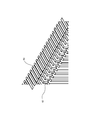
複数の物品20のそれぞれは、例えば凍結乾燥等の処理をされる薬品を保存しているバイアル等の容器であるが、特に限定されない。複数の物品20のそれぞれは、例えば、円柱形状を含む。より多くの物品20がプレート10上に配置されるよう、複数の物品20は、千鳥配置(Staggered arrangement)される。そのため、複数の物品20は、バー30の進行方向横側から見ると、重なり合うように配置されている。複数の物品20のそれぞれが円柱形状を含む場合、複数の物品20のそれぞれは、列ごとに、上方から見て、中心が互い違いになるよう配置されている。
Each of the plurality of articles 20 is, for example, a container such as a vial storing a drug to be processed such as lyophilization, but is not particularly limited. Each of the plurality of articles 20 includes, for example, a cylindrical shape. The plurality of articles 20 are staggered arrangement such that more articles 20 are disposed on the plate 10. Therefore, the plurality of articles 20 are arranged so as to overlap when viewed from the side of the advancing direction of the bar 30. In the case where each of the plurality of articles 20 includes a cylindrical shape, each of the plurality of articles 20 is arranged so that the centers are staggered with respect to each other in a row.
例えば、コンベヤー40側の一例目の物品20のそれぞれの中心に対して、二例目の物品20のそれぞれの中心は列方向にずれている。しかし、一例目の物品20のそれぞれの中心に対して、三列目の物品20のそれぞれの中心は、列方向において概ねずれていない。複数の物品20の中心は、三角格子状のパターンの格子点に配置されているとみなすことができる。ただし、本開示において、三角格子状のパターンをなす三角形は、正三角形であってもよいし、正三角形でなくてもよい。
For example, with respect to the centers of the first articles 20 on the conveyor 40 side, the centers of the second articles 20 are offset in the row direction. However, with respect to the center of each of the articles 20 of the first example, the center of each of the articles 20 in the third row is not substantially offset in the row direction. The centers of the plurality of articles 20 can be considered to be disposed at grid points of the triangular grid pattern. However, in the present disclosure, triangles forming a triangular lattice pattern may or may not be equilateral triangles.
複数の物品20を閉空間100から出す際には、閉空間100を提供している炉等の扉が開かれ、図4及び図5に示すように、バー30が、プレート10上の複数の物品20を、ブリッジ50を介して、コンベヤー40に向けて押し出す。バー30は、例えば、閉空間100内における複数の物品20の一番奥の列に接触可能な形状を有する。換言すれば、バー30は、プレート10上の複数の物品20のうち、コンベヤー40の反対側の物品20の列に接触可能な形状を有する。バー30の進行方向は、例えば、コンベヤー40の進行方向に対して垂直である。バー30は、複数の物品20が、一列ずつコンベヤー40に近接するよう、複数の物品20をコンベヤー40に段階的に押し出す。プレート10及びブリッジ50近傍には、バー30で押された物品20が、バー30の進行方向に対して横方向に広がらないようにするガイド70が設けられていてもよい。
When the plurality of articles 20 are taken out of the closed space 100, a door such as a furnace providing the closed space 100 is opened, and the bars 30 are arranged on the plate 10 as shown in FIGS. The articles 20 are pushed towards the conveyor 40 via the bridge 50. The bar 30 has, for example, a shape that can contact the innermost row of the plurality of articles 20 in the closed space 100. In other words, the bar 30 has a shape that can contact the row of the articles 20 on the opposite side of the conveyor 40 among the plurality of articles 20 on the plate 10. The traveling direction of the bar 30 is, for example, perpendicular to the traveling direction of the conveyor 40. The bars 30 progressively push the articles 20 onto the conveyor 40 such that the articles 20 are in close proximity to the conveyor 40, one row at a time. In the vicinity of the plate 10 and the bridge 50, a guide 70 may be provided to prevent the articles 20 pushed by the bar 30 from spreading in the lateral direction with respect to the advancing direction of the bar 30.
ブリッジ50は、例えば、プレート10に隣接する平坦部51と、コンベヤー40に隣接する櫛状部52と、を備える。図6及び図7に示すように、複数の傾斜リフト60は、ブリッジ50の櫛状部52の複数の間隙から突出可能である。バー30の進行方向に対して垂直方向における櫛状部52の間隙の幅は、物品20の幅よりも小さい。傾斜リフト60の傾斜面61は、平坦面62に対してコンベヤー40側に位置し、傾斜リフト60の平坦面62は、傾斜面61に対してプレート10側に位置する。傾斜面61は、コンベヤー40側からプレート10側に向かって、高くなるよう傾斜している。
The bridge 50 comprises, for example, a flat 51 adjacent to the plate 10 and a comb 52 adjacent to the conveyor 40. As shown in FIGS. 6 and 7, the plurality of inclined lifts 60 can protrude from the plurality of gaps of the comb 52 of the bridge 50. The width of the interstices of the combs 52 in the direction perpendicular to the direction of travel of the bar 30 is smaller than the width of the article 20. The inclined surface 61 of the inclined lift 60 is located on the conveyor 40 side with respect to the flat surface 62, and the flat surface 62 of the inclined lift 60 is located on the plate 10 side with respect to the inclined surface 61. The inclined surface 61 is inclined to be higher from the conveyor 40 side to the plate 10 side.
図2及び図3に示したように、傾斜リフト60がブリッジ50の下方から上昇すると、傾斜面61が、コンベヤー40の近傍のブリッジ50上に配置された少なくとも一列の物品20のそれぞれの底面等に接触する。傾斜リフト60が上昇するにつれて、物品20は傾斜面61によってプレート10側からコンベヤー40側に押され、傾斜面61の物品20に接触する部分が、プレート10側からコンベヤー40側にずれていく。これにより、物品20がブリッジ50からコンベヤー40に押し出されるとともに、コンベヤー40に押し出された物品20の列と、その列に隣接し、コンベヤー40で次に搬送されるべき物品20の列と、の間に、間隔が生じる。そのため、コンベヤー40に押し出された物品20の列と、その列に隣接し、コンベヤー40で次に搬送されるべき物品20の列と、が接触しなくなる。
As shown in FIGS. 2 and 3, as the inclined lift 60 ascends from below the bridge 50, the inclined surface 61 is the bottom or the like of each of the rows of articles 20 arranged on the bridge 50 near the conveyor 40. Contact As the inclined lift 60 ascends, the article 20 is pushed from the plate 10 to the conveyor 40 by the inclined surface 61, and the portion of the inclined surface 61 in contact with the article 20 shifts from the plate 10 to the conveyor 40. This causes the articles 20 to be pushed out of the bridge 50 onto the conveyor 40 and of the line of articles 20 pushed out onto the conveyor 40 and of the line of articles 20 to be conveyed next on the conveyor 40 adjacent to the line. There is an interval between them. Therefore, the row of the articles 20 pushed out to the conveyor 40 and the row of the articles 20 to be conveyed next on the conveyor 40 next to the row do not come in contact with each other.
傾斜リフト60の平坦面62は、押し出される物品20の列に隣接する物品20の少なくとも一列を持ち上げる。平坦面62は、ブリッジ50の表面と平行であるため、平坦面62に載っている物品20には、傾斜リフト60の上昇方向に対して横方向の力はほとんど又は全く加わらない。そのため、平坦面62上の物品は、傾斜リフト60の上昇方向に対して横方向にはほとんど又は全く動かない。
The flat surface 62 of the tilt lift 60 lifts at least one row of articles 20 adjacent to the row of articles 20 being extruded. Because the flat surface 62 is parallel to the surface of the bridge 50, the article 20 resting on the flat surface 62 experiences little or no lateral force with respect to the direction of elevation of the tilt lift 60. Therefore, the articles on the flat surface 62 move little or no in the lateral direction with respect to the rising direction of the tilt lift 60.
図8に示すように、バー30の進行方向における傾斜リフト60の平坦面62の幅wFは、例えば、下記式(3)で与えられてもよい。
wF=(n+1)dsinθ-d-mF (3)
nは自然数であり、平坦面62で持ち上げられる物品20の列の数に対応する。平坦面62で持ち上げられる物品20の列が一列である場合は、n=1である。図9に示すように、平坦面62で持ち上げられる物品20の列が二列である場合は、n=2である。dは平坦面62で持ち上げられる物品20の直径である。θは、三角格子状のパターンをなす三角形の内角のうち、平坦面62で持ち上げられる物品20の中心を頂点とする内角である。複数の物品20が密に充填されている場合、内角θは60°であるが、物品20どうしの間に隙間があったり、物品20の直径dにばらつきがあったりすると、内角θは60°でない場合がある。mFは任意のマージン量である。マージン量mFは、複数の物品20の直径dのばらつきや、複数の物品20の配置のばらつきに応じて、適宜設定される。 As shown in FIG. 8, the width w F of theflat surface 62 of the inclined lift 60 in the traveling direction of the bar 30 may be given by, for example, the following formula (3).
w F = (n + 1) d sin θ-d-m F (3)
n is a natural number and corresponds to the number of rows ofarticles 20 lifted by the flat surface 62. If the row of articles 20 lifted by the flat surface 62 is a single row, then n = 1. If two rows of articles 20 are lifted by flat surface 62, as shown in FIG. 9, then n = 2. d is the diameter of the article 20 lifted by the flat surface 62. θ is an inner angle with the center of the article 20 lifted by the flat surface 62 as the vertex among the inner angles of the triangle forming the triangular lattice pattern. When the plurality of articles 20 are densely packed, the inner angle θ is 60 °, but if there is a gap between the articles 20 or if the diameter d of the articles 20 varies, the inner angle θ is 60 ° It may not be. m F is an arbitrary margin amount. The margin amount m F is appropriately set in accordance with the variation in the diameter d of the plurality of articles 20 and the variation in the arrangement of the plurality of articles 20.
wF=(n+1)dsinθ-d-mF (3)
nは自然数であり、平坦面62で持ち上げられる物品20の列の数に対応する。平坦面62で持ち上げられる物品20の列が一列である場合は、n=1である。図9に示すように、平坦面62で持ち上げられる物品20の列が二列である場合は、n=2である。dは平坦面62で持ち上げられる物品20の直径である。θは、三角格子状のパターンをなす三角形の内角のうち、平坦面62で持ち上げられる物品20の中心を頂点とする内角である。複数の物品20が密に充填されている場合、内角θは60°であるが、物品20どうしの間に隙間があったり、物品20の直径dにばらつきがあったりすると、内角θは60°でない場合がある。mFは任意のマージン量である。マージン量mFは、複数の物品20の直径dのばらつきや、複数の物品20の配置のばらつきに応じて、適宜設定される。 As shown in FIG. 8, the width w F of the
w F = (n + 1) d sin θ-d-m F (3)
n is a natural number and corresponds to the number of rows of
上記(3)式中の(n+1)dsinθ-dは、持ち上げられる物品20の直径から、持ち上げられる物品20の列の両側のそれぞれに生じるくぼみの深さのうち、隣接する物品20が入り込むことができる深さの両側分を引いた長さに相当する。傾斜リフト60の平坦面62の幅wFが(n+1)dsinθ-dを超えると、傾斜リフト60が上昇する際、平坦面62で上昇させる物品20の列に隣接する物品20にも平坦面が接触し、平坦面62で上昇させる物品20の列に隣接する物品20が転倒する場合がある。
The (n + 1) d sin θ-d in the above equation (3) is that the adjacent article 20 of the depths of the depressions produced on both sides of the row of the articles 20 to be lifted may enter from the diameter of the articles 20 to be lifted. It corresponds to the length obtained by subtracting the two sides of the possible depth. When the width w F of the flat surface 62 of the tilt lift 60 exceeds (n + 1) d sin θ-d, the flat surface 62 is also flat on the article 20 adjacent to the row of articles 20 raised by the flat surface 62 when the tilt lift 60 is elevated. The articles 20 adjacent to the row of articles 20 in contact and raised by the flat surface 62 may tip over.
図10に示すように、バー30の進行方向における傾斜リフト60の傾斜面61の幅wTは、例えば、下記式(4)で与えられてもよい。
wT≧d-dsinθ+mT (4)
d及びθは、(3)式と同様である。mTは任意のマージン量である。マージン量mTは、複数の物品20の直径dのばらつきや、複数の物品20の配置のばらつきに応じて、適宜設定される。上記(4)式中のd-dsinθは、持ち上げられる物品20の列の両側のそれぞれに生じるくぼみの深さのうち、隣接する物品20が入り込むことができる深さに相当する。傾斜リフト60の傾斜面61の幅wTがd-dsinθより小さいと、傾斜リフト60の傾斜面61で押される物品20の列が、傾斜リフト60の平坦面62で持ち上げられる物品20の列から分離できない場合がある。 As shown in FIG. 10, the width w T of theinclined surface 61 of the inclined lift 60 in the traveling direction of the bar 30 may be given by the following equation (4), for example.
w T d d-d sin θ + m T (4)
d and θ are the same as in equation (3). m T is an arbitrary margin amount. The margin amount m T is appropriately set in accordance with the variation in the diameter d of the plurality ofarticles 20 and the variation in the arrangement of the plurality of articles 20. The d-d sin θ in the above equation (4) corresponds to the depth to which the adjacent articles 20 can enter, among the depths of the depressions produced on both sides of the row of articles 20 to be lifted. If the width w T of the inclined surface 61 of the inclined lift 60 is smaller than d-d sin θ, the row of articles 20 pushed by the inclined surface 61 of the inclined lift 60 is from the row of articles 20 lifted by the flat surface 62 of the inclined lift 60 Sometimes it can not be separated.
wT≧d-dsinθ+mT (4)
d及びθは、(3)式と同様である。mTは任意のマージン量である。マージン量mTは、複数の物品20の直径dのばらつきや、複数の物品20の配置のばらつきに応じて、適宜設定される。上記(4)式中のd-dsinθは、持ち上げられる物品20の列の両側のそれぞれに生じるくぼみの深さのうち、隣接する物品20が入り込むことができる深さに相当する。傾斜リフト60の傾斜面61の幅wTがd-dsinθより小さいと、傾斜リフト60の傾斜面61で押される物品20の列が、傾斜リフト60の平坦面62で持ち上げられる物品20の列から分離できない場合がある。 As shown in FIG. 10, the width w T of the
w T d d-d sin θ + m T (4)
d and θ are the same as in equation (3). m T is an arbitrary margin amount. The margin amount m T is appropriately set in accordance with the variation in the diameter d of the plurality of
第1実施形態に係る搬送装置によれば、プレート10上で複数の物品20が千鳥配置されていても、コンベヤー40で運ばれる物品20の列が、次にコンベヤー40で運ばれる物品20の列から確実に分離されるため、コンベヤー40で運ばれる物品20の列が、次にコンベヤー40で運ばれる物品20の列に接触しない。そのため、次にコンベヤー40で運ばれる物品20が、コンベヤー40で運ばれる物品20の列内に引き出されて混入したり、物品20が転倒したりしない。したがって、コンベヤー40で運ばれた物品20を抜き取り検査する際に、抜き取られた物品20が、プレート10上のどこに配置されていたかをトレースできることが可能である。
According to the transport apparatus of the first embodiment, even if the plurality of articles 20 are arranged in a staggered manner on the plate 10, the row of articles 20 carried by the conveyor 40 is the next row of articles 20 carried by the conveyor 40. So that the row of articles 20 carried by the conveyor 40 does not contact the row of articles 20 next carried by the conveyor 40. Therefore, the articles 20 conveyed by the conveyor 40 are not drawn out and mixed in the row of the articles 20 conveyed by the conveyor 40, and the articles 20 do not fall over. Thus, it is possible to trace where on the plate 10 the extracted articles 20 were placed when the articles 20 carried by the conveyor 40 are extracted and inspected.
(第2実施形態)
第2実施形態に係る搬送装置は、図11及び図12に示すように、傾斜リフト60のプレート10側の隣に配置された、ブリッジ50表面と平行な平坦面66を備える、ブリッジ50の下方から突出可能な平坦リフト65をさらに備える。図12に示すように、物品20の幅が、傾斜リフト60の平坦面62の幅より大きい場合、平坦リフト65がブリッジの下方から突出する際に、平坦リフト65の平坦面66が、傾斜リフト60の平坦面62で持ち上げられる物品20の列を共に持ち上げることができる。第2実施形態に係る搬送装置のその他の構成要素は、第1実施形態と同様であってもよい。 Second Embodiment
The transport apparatus according to the second embodiment, as shown in FIGS. 11 and 12, includes aflat surface 66 parallel to the surface of the bridge 50 disposed adjacent to the plate 10 side of the inclined lift 60, below the bridge 50. It further comprises a flat lift 65 which can protrude from the As shown in FIG. 12, when the width of the article 20 is larger than the width of the flat surface 62 of the tilt lift 60, the flat surface 66 of the flat lift 65 tilts when the flat lift 65 protrudes from below the bridge. Sixty flat surfaces 62 can lift the rows of articles 20 raised together. The other components of the transfer apparatus according to the second embodiment may be similar to those of the first embodiment.
第2実施形態に係る搬送装置は、図11及び図12に示すように、傾斜リフト60のプレート10側の隣に配置された、ブリッジ50表面と平行な平坦面66を備える、ブリッジ50の下方から突出可能な平坦リフト65をさらに備える。図12に示すように、物品20の幅が、傾斜リフト60の平坦面62の幅より大きい場合、平坦リフト65がブリッジの下方から突出する際に、平坦リフト65の平坦面66が、傾斜リフト60の平坦面62で持ち上げられる物品20の列を共に持ち上げることができる。第2実施形態に係る搬送装置のその他の構成要素は、第1実施形態と同様であってもよい。 Second Embodiment
The transport apparatus according to the second embodiment, as shown in FIGS. 11 and 12, includes a
物品20の大きさに応じて、図11に示すように、傾斜リフト60のみがブリッジ50の下方から突出してもよいし、図12に示すように、傾斜リフト60及び平坦リフト65の両方がブリッジ50の下方から突出してもよい。具体的には、図11に示すように、物品20が傾斜リフト60の平坦面62のみで持ち上げ可能な大きさである場合は、傾斜リフト60のみがブリッジ50の下方から突出してもよい。また、図12に示すように、物品20の大きさが、傾斜リフト60の平坦面62のみで持ち上げ可能な大きさより大きい場合は、傾斜リフト60及び平坦リフト65の両方がブリッジ50の下方から突出してもよい。
Depending on the size of the article 20, as shown in FIG. 11, only the tilt lift 60 may project from below the bridge 50, and as shown in FIG. 12, both the tilt lift 60 and the flat lift 65 are bridges. It may project from below 50. Specifically, as shown in FIG. 11, when the article 20 is sized to be lifted by only the flat surface 62 of the inclined lift 60, only the inclined lift 60 may project from below the bridge 50. Further, as shown in FIG. 12, when the size of the article 20 is larger than the size that can be lifted by only the flat surface 62 of the tilt lift 60, both the tilt lift 60 and the flat lift 65 project from below the bridge 50. May be
第2実施形態に係る搬送装置は、傾斜リフト60に隣接する複数の平坦リフトを備えていてもよい。この場合、物品20の大きさに応じて、ブリッジの下方から突出させる平坦リフトの数を選択してもよい。
The transport apparatus according to the second embodiment may include a plurality of flat lifts adjacent to the tilt lift 60. In this case, depending on the size of the article 20, the number of flat lifts to be protruded from below the bridge may be selected.
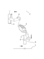
図13に示すように、第2実施形態に係る搬送装置は、傾斜リフト60を移動させるプッシャー91、平坦リフト65を移動させるプッシャー92、並びに傾斜リフト60及び平坦リフト65の移動方向を規定するリフトガイド81、82を備えていてもよい。プッシャー91、92は、傾斜リフト60及び平坦リフト65に接触する部材であり、例えば、アクチュエーターやモーター等で駆動される。また、平坦リフト65は、傾斜リフト60の底辺に回り込む回り込み接触部67を備えていてもよい。この場合、プッシャー92が平坦リフト65を持ち上げると、回り込み接触部67を介して、傾斜リフト60にも力が伝わり、傾斜リフト60も持ち上げられる。
As shown in FIG. 13, the transfer device according to the second embodiment includes a pusher 91 for moving the inclined lift 60, a pusher 92 for moving the flat lift 65, and a lift for defining the moving directions of the tilt lift 60 and the flat lift 65. Guides 81 and 82 may be provided. The pushers 91 and 92 are members that come in contact with the tilt lift 60 and the flat lift 65, and are driven by, for example, an actuator or a motor. Also, the flat lift 65 may include a wrap around contact portion 67 that wraps around the bottom of the tilt lift 60. In this case, when the pusher 92 lifts the flat lift 65, a force is also transmitted to the tilt lift 60 via the wraparound contact portion 67, and the tilt lift 60 is also lifted.
例えば、第2実施形態に係る搬送装置は、図14に示すように、回転装置201と、回転装置201によって回転させられる第1リンク202と、第1リンク202とプッシャー91の間に接続された第2リンク203と、同じく回転装置201によって回転させられる第3リンク204と、第3リンク204とプッシャー92の間に接続された第4リンク205と、を備えていていてもよい。このとき回転装置の一方の軸は第1リンク202に接続され、他方の軸は第3リンク204に接続され、回転装置201の回転トルクにより第1リンク202と第3リンク204は同時に同じ方向に回転する。回転装置201としてはモーター等が使用可能である。
For example, as illustrated in FIG. 14, the transport device according to the second embodiment is connected between the rotating device 201, the first link 202 rotated by the rotating device 201, and the first link 202 and the pusher 91. A second link 203, a third link 204 which is also rotated by the rotation device 201, and a fourth link 205 connected between the third link 204 and the pusher 92 may be provided. At this time, one axis of the rotating device is connected to the first link 202, and the other axis is connected to the third link 204, and the rotational torque of the rotating device 201 causes the first link 202 and the third link 204 simultaneously in the same direction. Rotate. As the rotating device 201, a motor or the like can be used.
図15に示すように、回転装置201が第1リンク202を反時計回りさせると、第1リンク202と第2リンク203との伸展運動によりプッシャー91が上昇する。また、同時に、回転装置201が第3リンク204を反時計回りさせると、第3リンク204と第4リンク205との屈曲運動によりプッシャー92が下降する。この場合、図13に示すプッシャー91に接触する傾斜リフト60のみを上昇させることが可能である。これに対し、図16に示すように、回転装置201が第1リンク202を時計回りさせると、第1リンク202と第2リンク2-2との屈曲運動によりプッシャー91が下降する。また、同時に、回転装置201が第3リンク204を時計回りさせると、第3リンク204と第4リンク205との伸展運動によりプッシャー92が上昇する。この場合、図13に示すプッシャー92に接触する平坦リフト65と共に、平坦リフト65の回り込み接触部67に接触する傾斜リフト60を上昇させることが可能である。このように、リンク機構を用いることにより、1つの回転装置201で、プッシャー91、92のいずれかを上昇させることが可能である。なお、リンクの設定により、回転装置201で生じる回転力の方向と、プッシャー91、92のそれぞれの移動方向と、の組み合わせは、任意に組み合わせることが可能である。
As shown in FIG. 15, when the rotation device 201 rotates the first link 202 counterclockwise, the pusher 91 is lifted by the extension movement of the first link 202 and the second link 203. At the same time, when the rotation device 201 rotates the third link 204 counterclockwise, the pusher 92 is lowered by the bending movement of the third link 204 and the fourth link 205. In this case, it is possible to raise only the inclined lift 60 in contact with the pusher 91 shown in FIG. On the other hand, as shown in FIG. 16, when the rotating device 201 rotates the first link 202 clockwise, the pusher 91 is lowered by the bending movement of the first link 202 and the second link 2-2. Also, at the same time, when the rotating device 201 rotates the third link 204 clockwise, the pusher 92 is lifted by the extension movement of the third link 204 and the fourth link 205. In this case, along with the flat lift 65 contacting the pusher 92 shown in FIG. 13, it is possible to raise the inclined lift 60 contacting the wraparound contact portion 67 of the flat lift 65. Thus, it is possible to raise either of the pushers 91, 92 with one rotation device 201 by using the link mechanism. In addition, it is possible to combine arbitrarily the combination of the direction of the rotational force which generate | occur | produces with the rotation apparatus 201, and each moving direction of the pushers 91 and 92 by setting of a link.
プレート10上に配置される物品20の大きさは、毎回同じでない場合がある。これに対し、第2実施形態に係る搬送装置によれば、物品20の大きさが変わっても、コンベヤー40で運ばれる物品20の列を、次にコンベヤー40で運ばれる物品20の列から確実に分離することが可能である。
The size of the articles 20 placed on the plate 10 may not be the same each time. On the other hand, according to the transport device of the second embodiment, even if the size of the articles 20 changes, the row of the articles 20 carried by the conveyor 40 is secured from the row of the articles 20 carried next by the conveyor 40 It is possible to separate
(他の実施形態)
上記のように本発明を実施の形態によって記載したが、この開示の一部をなす記述及び図面はこの発明を限定するものであると理解するべきではない。この開示から当業者には様々な代替実施の形態、実施例及び運用技術が明らかになるはずである。例えば、炉内外に搬送される物品は医薬品を含むことに限定されず、食品、飲料、及び精密部品等でもよいし、その他、あらゆる物品を含む。炉は、凍結乾燥炉に限定されず、発酵炉でもよく、あるいは内部の温度分布ムラの抑制、及び発塵の抑制が望まれる、あらゆる炉を含む。このように、本発明はここでは記載していない様々な実施の形態等を包含するということを理解すべきである。 (Other embodiments)
Although the present invention has been described by the embodiment as described above, it should not be understood that the description and the drawings, which form a part of this disclosure, limit the present invention. Various alternative embodiments, examples and operation techniques should be apparent to those skilled in the art from this disclosure. For example, the articles to be transported in and out of the furnace are not limited to containing medicines, but may be foods, beverages, precision parts, etc., and any other articles. The furnace is not limited to the lyophilization furnace, and may be a fermentation furnace, or any furnace for which it is desired to suppress the internal temperature distribution unevenness and the dust generation. As such, it should be understood that the present invention includes various embodiments and the like not described herein.
10・・・プレート、20・・・物品、30・・・バー、40・・・コンベヤー、50・・・ブリッジ、51・・・平坦部、52・・・櫛状部、60・・・傾斜リフト、61・・・傾斜面、62・・・平坦面、65・・・平坦リフト、66・・・平坦面、67・・・回り込み接触部、70・・・ガイド、81・・・リフトガイド、91、92・・・プッシャー、100・・・閉空間、201・・・回転装置、202・・・第1リンク、203・・・第2リンク、204・・・第3リンク、205・・・第4リンク
DESCRIPTION OF SYMBOLS 10 ... Plate, 20 ... article 30, 30 ... bar, 40 ... conveyor, 50 ... bridge, 51 ... flat part, 52 ... comb-like part, 60 ... inclination Lift, 61: inclined surface, 62: flat surface, 65: flat lift, 66: flat surface, 67: wraparound contact portion, 70: guide, 81: lift guide 91, 92: pusher, 100: closed space, 201: rotation device, 202: first link, 203: second link, 204: third link, 205.・ 4th link
Claims (10)
- プレートと、
前記プレート上に千鳥配置された複数の物品を押すバーと、
前記プレートから押し出された前記物品の列を搬送するコンベヤーと、
前記プレートと前記コンベヤーの間に配置されたブリッジと、
前記ブリッジ表面に対して傾斜している傾斜面と、前記ブリッジ表面と平行な平坦面と、を備える、前記ブリッジの下方から突出可能な傾斜リフトであって、当該傾斜リフトが前記ブリッジの下方から突出する際に、前記傾斜面が、前記物品の少なくとも一列を前記ブリッジから前記コンベヤーに押し出し、前記平坦面が、前記押し出される物品の列に隣接する物品の少なくとも一列を持ち上げる、傾斜リフトと、
を備える搬送装置。 Plate,
A bar for pushing a plurality of articles arranged in a zigzag on the plate;
A conveyor for conveying the row of articles pushed out of the plate;
A bridge disposed between the plate and the conveyor;
An inclined lift that can be projected from the bottom of the bridge, comprising an inclined surface that is inclined with respect to the bridge surface and a flat surface parallel to the bridge surface, the inclined lift being from the bottom of the bridge An inclined lift, wherein, when projecting, the inclined surface pushes at least one row of articles from the bridge to the conveyor, and the flat surface lifts at least one row of articles adjacent to the row of extruded articles;
A transport device comprising: - 前記ブリッジが櫛状であり、前記傾斜リフトが前記櫛状のブリッジの間隙から突出する、請求項1に記載の搬送装置。 The transport device according to claim 1, wherein the bridge is comb-shaped and the inclined lift projects from the gap of the comb-shaped bridge.
- 前記複数の物品のそれぞれは円柱形状を含み、
前記複数の物品の中心が三角格子状に配置されており、
前記傾斜リフトの平坦面の幅wFが下記式(1)で与えられる、請求項1又は2に記載の搬送装置。
wF=(n+1)dsinθ-d-mF (1)
ただし、nは前記平坦面で持ち上げられる前記物品の列の数に対応する自然数であり、dは前記物品の直径であり、θは前記三角格子状のパターンをなす三角形の内角であり、mFは任意のマージン量である。 Each of the plurality of articles includes a cylindrical shape,
The centers of the plurality of articles are arranged in a triangular lattice,
The transport apparatus according to claim 1, wherein the width w F of the flat surface of the inclined lift is given by the following formula (1).
w F = (n + 1) d sin θ-d-m F (1)
Where n is a natural number corresponding to the number of rows of the articles lifted by the flat surface, d is the diameter of the articles, θ is the interior angle of triangles forming the triangular grid pattern, and m F Is an arbitrary margin amount. - 前記複数の物品のそれぞれは円柱形状を含み、
前記複数の物品の中心が三角格子状に配置されており、
前記傾斜リフトの傾斜面の幅wTが下記式(2)で与えられる、請求項1又は2に記載の搬送装置。
wT≧d-dsinθ+mT (2)
ただし、dは前記物品の直径であり、θは前記三角格子状のパターンをなす三角形の内角であり、mTは任意のマージン量である。 Each of the plurality of articles includes a cylindrical shape,
The centers of the plurality of articles are arranged in a triangular lattice,
The conveying apparatus according to claim 1, wherein the width w T of the inclined surface of the inclined lift is given by the following equation (2).
w T d d-d sin θ + m T (2)
Where d is the diameter of the article, θ is the interior angle of the triangle forming the triangular grid pattern, and m T is an arbitrary margin amount. - 前記傾斜リフトの隣に配置された、前記ブリッジ表面と平行な平坦面を備える、前記ブリッジの下方から突出可能な平坦リフトであって、当該平坦リフトが前記ブリッジの下方から突出する際に、当該平坦リフトの平坦面が、前記傾斜リフトの平坦面で持ち上げられる物品の列を共に持ち上げる、平坦リフトをさらに備える、請求項1から4のいずれか1項に記載の搬送装置。 A flat lift, which can be projected from below the bridge, with a flat surface arranged next to the inclined lift and parallel to the bridge surface, when the flat lift projects from below the bridge 5. A transport apparatus according to any one of the preceding claims, wherein the flat lift flat surface further comprises a flat lift, which lifts together a row of articles lifted by the flat lift flat surface.
- 前記ブリッジの下方から前記傾斜リフトのみが突出可能である、請求項5に記載の搬送装置。 The transport apparatus according to claim 5, wherein only the inclined lift can project from below the bridge.
- 前記ブリッジの下方から前記傾斜リフト及び前記平坦リフトの両方が突出可能である、請求項5に記載の搬送装置。 The transport apparatus according to claim 5, wherein both the tilt lift and the flat lift can project from below the bridge.
- 前記プレートが閉空間内に配置されている、請求項1から5のいずれか1項に記載の搬送装置。 6. Transport device according to any of the preceding claims, wherein the plate is arranged in a closed space.
- 前記閉空間内において、温度及び圧力の少なくとも一方が管理される、請求項8に記載の搬送装置。 The transport apparatus according to claim 8, wherein at least one of temperature and pressure is managed in the closed space.
- 前記閉空間内において、温度分布及び圧力分布の少なくとも一方が管理される、請求項8に記載の搬送装置。 The transport apparatus according to claim 8, wherein at least one of a temperature distribution and a pressure distribution is managed in the closed space.
Priority Applications (1)
| Application Number | Priority Date | Filing Date | Title |
|---|---|---|---|
| PCT/JP2017/041359 WO2019097648A1 (en) | 2017-11-16 | 2017-11-16 | Transport device |
Applications Claiming Priority (1)
| Application Number | Priority Date | Filing Date | Title |
|---|---|---|---|
| PCT/JP2017/041359 WO2019097648A1 (en) | 2017-11-16 | 2017-11-16 | Transport device |
Publications (1)
| Publication Number | Publication Date |
|---|---|
| WO2019097648A1 true WO2019097648A1 (en) | 2019-05-23 |
Family
ID=66538810
Family Applications (1)
| Application Number | Title | Priority Date | Filing Date |
|---|---|---|---|
| PCT/JP2017/041359 WO2019097648A1 (en) | 2017-11-16 | 2017-11-16 | Transport device |
Country Status (1)
| Country | Link |
|---|---|
| WO (1) | WO2019097648A1 (en) |
Citations (6)
| Publication number | Priority date | Publication date | Assignee | Title |
|---|---|---|---|---|
| JPS4730384U (en) * | 1971-04-28 | 1972-12-06 | ||
| JP2008507460A (en) * | 2004-07-22 | 2008-03-13 | アイエムエイ‐テルスター、ソシエダッド、リミターダ | Equipment for loading and unloading containers |
| US20090208320A1 (en) * | 2008-02-19 | 2009-08-20 | Accuro Gmbh | Method of separating a number of vials from a plurality of vials disposed in several rows and apparatus therefor |
| JP2011219188A (en) * | 2010-04-05 | 2011-11-04 | Kao Corp | Article aligning device |
| JP2014189369A (en) * | 2013-03-27 | 2014-10-06 | Toshiba Mitsubishi-Electric Industrial System Corp | Container conveyer |
| JP2016090075A (en) * | 2014-10-30 | 2016-05-23 | アズビル株式会社 | Thermal management device, transport device and transportation block |
-
2017
- 2017-11-16 WO PCT/JP2017/041359 patent/WO2019097648A1/en active Application Filing
Patent Citations (6)
| Publication number | Priority date | Publication date | Assignee | Title |
|---|---|---|---|---|
| JPS4730384U (en) * | 1971-04-28 | 1972-12-06 | ||
| JP2008507460A (en) * | 2004-07-22 | 2008-03-13 | アイエムエイ‐テルスター、ソシエダッド、リミターダ | Equipment for loading and unloading containers |
| US20090208320A1 (en) * | 2008-02-19 | 2009-08-20 | Accuro Gmbh | Method of separating a number of vials from a plurality of vials disposed in several rows and apparatus therefor |
| JP2011219188A (en) * | 2010-04-05 | 2011-11-04 | Kao Corp | Article aligning device |
| JP2014189369A (en) * | 2013-03-27 | 2014-10-06 | Toshiba Mitsubishi-Electric Industrial System Corp | Container conveyer |
| JP2016090075A (en) * | 2014-10-30 | 2016-05-23 | アズビル株式会社 | Thermal management device, transport device and transportation block |
Similar Documents
| Publication | Publication Date | Title |
|---|---|---|
| EP0230756B1 (en) | Apparatus and method for packaging articles | |
| JP3816160B2 (en) | Container unloading device | |
| US3513623A (en) | Apparatus for end-loading cartons | |
| JPS62168818A (en) | Packaging machine and packaging method | |
| WO2019097648A1 (en) | Transport device | |
| KR20180068858A (en) | Container transporting apparatus | |
| US3491508A (en) | Inverted case loader | |
| JP5837181B2 (en) | Container filling device | |
| JP4341974B2 (en) | Container unloading device | |
| US9586706B2 (en) | Apparatus and methods for loading product into cases | |
| KR100215714B1 (en) | Method for packing noodle containers in a box | |
| WO2019198240A1 (en) | Transport device and furnace system | |
| JP4880307B2 (en) | Boxing equipment | |
| WO2019198244A1 (en) | Transport device | |
| WO2019198243A1 (en) | Transport device | |
| JPH05301624A (en) | Alignment method for container and its device | |
| JPS63185712A (en) | Carrier mechanism for vacuum deposition device | |
| JP4773752B2 (en) | Bar-shaped article stacking device | |
| JP2009012794A (en) | Caser | |
| JPH0569933A (en) | Container carrier device | |
| JP2016034865A (en) | Stacking device, and stacking method | |
| WO2019198148A1 (en) | Transport device and freeze-drying system | |
| JP5581889B2 (en) | Article alignment device | |
| JPH08151015A (en) | Parallelly transporting device | |
| JP5332191B2 (en) | Transfer equipment |
Legal Events
| Date | Code | Title | Description |
|---|---|---|---|
| 121 | Ep: the epo has been informed by wipo that ep was designated in this application |
Ref document number: 17932220 Country of ref document: EP Kind code of ref document: A1 |
|
| NENP | Non-entry into the national phase |
Ref country code: DE |
|
| 122 | Ep: pct application non-entry in european phase |
Ref document number: 17932220 Country of ref document: EP Kind code of ref document: A1 |
|
| NENP | Non-entry into the national phase |
Ref country code: JP |