WO2019097501A1 - 冷却塔送風機用ベルト伝動機構 - Google Patents
冷却塔送風機用ベルト伝動機構 Download PDFInfo
- Publication number
- WO2019097501A1 WO2019097501A1 PCT/IB2018/059406 IB2018059406W WO2019097501A1 WO 2019097501 A1 WO2019097501 A1 WO 2019097501A1 IB 2018059406 W IB2018059406 W IB 2018059406W WO 2019097501 A1 WO2019097501 A1 WO 2019097501A1
- Authority
- WO
- WIPO (PCT)
- Prior art keywords
- belt
- pulley
- tension
- blower
- cooling tower
- Prior art date
- Legal status (The legal status is an assumption and is not a legal conclusion. Google has not performed a legal analysis and makes no representation as to the accuracy of the status listed.)
- Ceased
Links
Images


Classifications
-
- F—MECHANICAL ENGINEERING; LIGHTING; HEATING; WEAPONS; BLASTING
- F16—ENGINEERING ELEMENTS AND UNITS; GENERAL MEASURES FOR PRODUCING AND MAINTAINING EFFECTIVE FUNCTIONING OF MACHINES OR INSTALLATIONS; THERMAL INSULATION IN GENERAL
- F16H—GEARING
- F16H7/00—Gearings for conveying rotary motion by endless flexible members
- F16H7/02—Gearings for conveying rotary motion by endless flexible members with belts; with V-belts
-
- F—MECHANICAL ENGINEERING; LIGHTING; HEATING; WEAPONS; BLASTING
- F16—ENGINEERING ELEMENTS AND UNITS; GENERAL MEASURES FOR PRODUCING AND MAINTAINING EFFECTIVE FUNCTIONING OF MACHINES OR INSTALLATIONS; THERMAL INSULATION IN GENERAL
- F16H—GEARING
- F16H7/00—Gearings for conveying rotary motion by endless flexible members
- F16H7/08—Means for varying tension of belts, ropes or chains
- F16H7/10—Means for varying tension of belts, ropes or chains by adjusting the axis of a pulley
- F16H7/12—Means for varying tension of belts, ropes or chains by adjusting the axis of a pulley of an idle pulley
-
- F—MECHANICAL ENGINEERING; LIGHTING; HEATING; WEAPONS; BLASTING
- F28—HEAT EXCHANGE IN GENERAL
- F28F—DETAILS OF HEAT-EXCHANGE AND HEAT-TRANSFER APPARATUS, OF GENERAL APPLICATION
- F28F27/00—Control arrangements or safety devices specially adapted for heat-exchange or heat-transfer apparatus
Definitions
- the present invention relates to a cooling tower that cools a circulating heat medium in the liquid phase by heat exchange with air in a heat exchange unit, and more particularly, to a belt transmission mechanism for moving a ventilation fan in the cooling tower with a motor.
- a fan is operated in a heat exchange unit inside the cooling tower. Accordingly, the air (external air) and the heat medium, which are taken in from the outside, are thermally exchanged directly or indirectly to perform cooling.
- a blower used in such a cooling tower usually rotates an impeller by a motor, and conventionally, a driving power transmission mechanism such as a belt transmission mechanism is interposed between the impeller and the motor, and the motor is a blade.
- a driving power transmission mechanism such as a belt transmission mechanism
- the pulley was respectively arrange
- the belt transmission mechanism related to the drive of the blower in the conventional cooling tower is as shown in the patent document, and a V-belt is generally adopted as a belt for transmitting the driving force.
- V-belt When a V-belt is used as such a belt transmission mechanism, the V-belt fits into the V-shaped grooves provided on the outer circumferences of the pulleys on the motor side and the blower side to transmit the driving force.
- the meandering of the belt and the detachment from the pulley were hard to occur.
- the bending rigidity of the belt is large, and accordingly, there is a problem that the loss related to the driving force transmission becomes large.
- the present invention has been made to solve the above problems, and can use a flat belt as a transmission belt for a blower and appropriately arrange a tension adjustment unit that suppresses the meandering of the belt to prevent the belt from falling off. It is an object of the present invention to provide a belt transmission mechanism for a cooling tower fan, which can achieve efficient driving of an impeller while realizing maintenance free.
- the belt transmission mechanism for a cooling tower fan is a cooling tower for causing heat exchange between the air taken in from the outside by the induced draft by the fan and the heat medium to be cooled and the rotational driving force from the motor to the impeller of the fan.
- a drive-side pulley provided integrally with the output shaft of the electric motor
- a driven-side pulley provided integrally with the rotary shaft of the impeller of the blower
- the drive-side pulley A belt which is a flat belt stretched between the driven pulley and the drive pulley and the driven pulley is disposed, and a tension pulley in contact with the belt applies an urging force so that the belt is not bent.
- the tension pulley is arranged to be able to press the belt from the outside of the belt with respect to the part on the belt loosening side with respect to the belt traveling direction in the normal rotation state where induced drafting is performed. It is disposed so as to be located in a region where the distance from the rotation center position is about 35% or less of the distance between the driving pulley and the driven pulley.
- a flat belt is used as a transmission belt which is stretched between the driving pulley and the driven pulley, and the tension pulley in contact with the belt holds the belt so as not to bend.
- the tension adjustment section also has a function of controlling the movement of the belt in the width direction during traveling to suppress the meandering of the belt, and positioning the rotational center position of the tension pulley in a predetermined area near the driven pulley By pushing the looseness side of the belt with the tension pulley, the belt can be properly regulated by the tension pulley of the tension adjustment section, and the impeller of the fan rotates in the opposite direction to the normal operation by external force with the motor stopped.
- the displacement of the belt can be suppressed to prevent falling off each pulley, and the burden of maintenance can be reliably reduced.
- the loss of transmission can be suppressed using a flat belt, and an impeller can be driven efficiently.
- the belt transmission mechanism for a cooling tower fan comprises a supporting device for supporting the electric motor so as to be positionally adjustable to the side of the fan, if necessary.
- the motor is fixed in a predetermined motor supporting state in which the motor output shaft is inclined in advance such that the rotation center axis of the drive side pulley is parallel to the rotation center axis of the driven side pulley by the elastic deformation of
- the support device for supporting the motor in a position adjustable manner is provided, and the direction of the motor output shaft can be adjusted. Inclination is grasped in advance, and by setting the axis inclination angle in the opposite direction by position adjustment using this inclination amount, the inclination of the output shaft generated at the time of fan operation is canceled, and the driving side pulley at the time of fan operation And the driven pulley can be maintained, and an excessive force is not applied to the traveling belt, so that the meandering prevention function of the belt by the tension pulley of the tension adjusting unit can be appropriately exhibited.
- the belt transmission mechanism for a cooling tower fan may include a cover that covers the drive-side pulley, the driven-side pulley, the belt, and the tension adjustment unit, if necessary, And an opening that allows the inside and the outside of the cover to communicate with each other, and at least one or both of the motor output shaft peripheral portion under the drive side pulley and the impeller rotary shaft peripheral portion under the driven side pulley in the cover. At least an opening for allowing external air to flow is formed in the cover.
- the tension adjusting unit may have an arm portion supported so as to be capable of tilting around an axis parallel to the rotation center axis of the driven pulley, as necessary.
- the tension pulley is rotatably attached to the arm portion, and the entire arm portion is urged and inclined in a direction approaching the driven pulley by urging means so as to be in contact with the belt.
- the tension pulley of the tension adjustment unit is attached to the tilting arm, and is biased in a direction to approach the driven pulley by the biasing means, and contacts the belt, thereby tensioning.
- the pulley can be in contact with the belt and push it, and the mechanism for simultaneously suppressing the bending and meandering of the belt can be simplified and compact, and the tension adjustment part located on the air flow path of the fan can be minimized to reduce the air flow resistance.
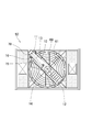
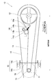
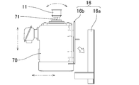
- FIGS. 1 to 5 a belt transmission mechanism according to an embodiment of the present invention will be described based on FIGS. 1 to 5.
- an example applied to a cooling tower in which two heat exchange units are disposed opposite to each other with a central portion having a fan for induction ventilation as a cross flow type will be described.
- the belt transmission mechanism 10 is for transmitting the driving force from the motor 70 to the blower 60 of the cooling tower 50, and more specifically, the output shaft of the motor 70 A drive-side pulley 11 disposed integrally with 71, a driven-side pulley 12 integrally disposed with a rotation shaft of an impeller 61 of the blower 60, a drive-side pulley 11 and a driven-side pulley 12
- the belt 13 to be delivered, the tension adjustment unit 14 that holds the belt 13 so as not to bend by the tension pulley 14 d in contact with the belt 13, the drive pulley 11, the driven pulley 12, the belt 13, and the tension adjuster 14
- the cover 15 is provided with a cover 15 and a support device 16 that supports the electric motor 70 on the side of the blower 60 so as to be adjustable in position.
- two heat exchange units are disposed opposite to each other across the central ventilation space as a cross flow type.
- the control system that performs the drive control of 70 is a known configuration, and the detailed description is omitted.
- An electric motor 70 is disposed on the side of the blower 60 in the cooling tower 50 via a support device 16. Then, the rotation of the output shaft 71 of the electric motor 70 is transmitted to the impeller 61 of the blower 60 by the belt transmission mechanism 10, and the impeller 61 rotates to execute induced ventilation.
- the drive-side pulley 11 is fixed to the output shaft 71 of the motor 70 and can be integrally rotated with the output shaft 71.
- the drive-side pulley 11 rotates with the rotation of the output shaft 71 of the motor 70, and is wound.
- the belt 13 that has been hung is caused to travel toward the tension pulley 14 d and the driven pulley 12 of the tension adjustment unit 14.
- the driven pulley 12 is fixed to the rotation shaft of the impeller 61 in the fan 60 and can be integrally rotated with the impeller 61.
- the driven pulley 12 is formed to have an outer diameter larger than that of the driving pulley 11, and is configured to rotate the impeller 61 at a lower rotational speed with respect to the output shaft 71 of the motor 70.
- the belt 13 is formed as an endless flat belt and is stretched between the driving pulley 11 and the driven pulley 12 and travels with the rotation of the driving pulley 11 to cause the driven pulley 12 to rotate. It is
- the tension adjustment unit 14 includes a base portion 14a fixedly installed at a position between the drive-side pulley 11 and the driven-side pulley 12 on the upper side of the blower 60, and rotation of the driven-side pulley 12 at one end of the base portion 14a.
- the arm 14b is attached to be tiltable about an axis parallel to the central axis, and the other end of the base 14a and the tip of the arm 14b are attached at both ends, and the tip of the arm 14b is the other end of the base 14a
- the spring 14c as biasing means for biasing in the direction approaching the part, and the tip of the arm 14b is rotatable around a central axis parallel to the rotational central axis of the driven pulley 12, and the position in the central axial direction is And a tension pulley 14d fitted to the position of the driven pulley 12 and mounted.
- the tension adjusting unit 14 is configured to tension the pulleys 14d with respect to a portion on the belt loosening side in the belt traveling direction in the normal operation state in which the blower 60 performs induced draft, among the portions stretched between the pulleys of the belt 13.
- the distance from the center of rotation of the driven pulley 12 is about 35% or less of the distance between the driving pulley 11 and the driven pulley 12 while the arrangement is such that the pressing of the rotation of the tension pulley 14d is from the center of rotation of the driven pulley 12 It is configured to be located in the area to be positioned, more preferably in the area to be approximately 24 to 31%.
- the base portion 14a of the tension adjusting portion 14 is biased in such a way that the arm portion 14b approaches the driven pulley 12 by the spring 14c and tilts, and the tension pulley 14d on the arm portion 14b presses the belt 13.
- it is configured to be fixed at a predetermined position near the driven pulley 12.
- the arm 14b is tilted in a predetermined direction with respect to the base 14a to move the tension pulley 14d, so that the main part of the tension adjustment unit 14 excluding the tension pulley 14d is
- the compact arrangement can be made on the lower side in a compact manner, and the air flow resistance of the fan 60 resulting from the arrangement of the tension adjustment portion 14 can be minimized.
- the tension pulley 14d contacts the flat belt which is stretched between the pulleys and travels, and prevents meandering of the flat belt and deviation in the belt width direction, for example, Japanese Patent No. 3600833 and Japanese Patent No. 4365713 It has a known meandering prevention mechanism as described in U.S. Pat.
- Such a tension pulley 14d is urged in a direction approaching the driven pulley 12 together with the arm portion 14b and is inclined to contact the belt 13 to apply a tension, thereby bending the belt 13 into a stretched state. While being held so as not to be bent, the movement in the width direction of the belt 13 can be controlled to suppress meandering and the like.
- the traveling direction of the belt 13 is temporarily reverse to the normal operating state of the blower 60. Even when the direction is changed, the meandering prevention function of the tension pulley 14d with respect to the belt 13 can be maintained, and the shift of the belt 13 can be suppressed to prevent the belt 13 from falling off each pulley.
- the blower of the cooling tower is reverse to the normal operation by the motor drive by the wind pressure applied to the impeller due to the flow of the outside air during strong wind or the like and the exhaust from other cooling towers closely arranged when the motor stops. It has the feature that the impeller can rotate in the direction.
- a tension belt having a flat belt and a meandering prevention mechanism corresponding thereto is temporarily provided near the drive-side pulley of the motor output shaft, similarly to a general blower in which reverse rotation of the impeller can not occur.
- the impeller rotates in the opposite direction to that in the normal operation, the relationship between the force applied to the belt from the tension pulley and the traveling direction of the belt changes
- the cover 15 is formed in a substantially box shape and disposed on the upper side of the blower 60 and covers the drive pulley 11, the driven pulley 12, the belt 13, and the tension adjustment unit 14.
- the cover 15 prevents water from going to the blower 60 from the outside such as rain, or water droplets contained in the air reaching the blower 60 from inside the cooling tower by induced draft reaching the respective parts of the transmission mechanism and giving an adverse effect.
- the tension adjustment portion peripheral portion of the cover 15 has no opening for communicating the inside and the outside of the cover. At the time when the cover 15 is provided, if there is a gap serving as an opening between the cover and another member adjacent to the tension adjustment portion 14, no elastic material or the like is inserted or filled. . By eliminating the opening around the tension adjusting unit 14, deterioration of the tension adjusting unit 14 is prevented by preventing water and damp air from inside the cooling tower from coming into contact with the tension adjusting unit 14.
- water is allowed to pass from the inside of the cover to at least one or both of the motor output shaft peripheral portion on the lower side of the drive side pulley 11 in the cover 15 and the impeller rotational axis side portion on the lower side of the driven side pulley 12 Make the opening exist.
- these portions of the cover 15 have at least through holes of a size that allows them to pass through
- the opening is provided from the beginning, and the opening can be formed as a part of such a through hole, that is, as a gap portion left without being blocked by a member such as a shaft passed through the through hole.
- the present invention is not limited to this, and through holes serving as openings may be separately formed in the motor output shaft peripheral portion of the cover 15 or the impeller rotary shaft peripheral portion.
- the openings around the motor output shaft of the cover 15 and around the impeller rotation shaft are directed downward and out of the flow path of the air blown by the blower 60. There is no risk of water from entering the cover.
- the support device 16 supports the motor 70 on the side of the blower 60 so as to be adjustable in position.
- the support device 16 includes a base 16a integrated with the blower 60, and an adjustment frame 16b attached to the base 16a so that the position and the direction with respect to the base 16a can be finely adjusted and the motor 70 is fixed. It is the composition provided.
- the rotation center axis of the drive side pulley 11 becomes the rotation center axis of the driven side pulley 12
- the support state of the motor 70 that is parallel is obtained by adjusting the position of the adjustment frame portion 16b with respect to the base portion 16a.
- a plurality of combinations of the size of the blower and the output of the motor for driving the blower are set in accordance with the required performance.
- the movement of the motor 70 on the support device 16 is fixed with the output shaft 71 in parallel with the fan rotation shaft.
- the inclination degree of the output shaft 71 when each part of the blower is elastically deformed by applying a force corresponding to a load is available as adjustment data.
- the position adjustment of the motor 70 using the support device 16 makes the known direction of the motor output shaft 71 on the opposite side to the side inclined when the fan is operated. To obtain a predetermined motor support state which is inclined by a predetermined angle corresponding to (see FIG. 5).
- the rotation center axis of the drive side pulley 11 becomes parallel to the rotation center axis of the driven side pulley 12, and the position in the center axis direction of the drive side pulley 11 is the position in the center axis direction of the driven side pulley 12
- the motor 70 can be fixed such that the direction of the belts stretched around these two pulleys is perpendicular to the central axis direction of each pulley.
- the blower is commissioned at each installation site of the cooling tower to grasp the positional deviation between the pulleys due to the deformation of each part of the blower in the operating state. Then, based on that, it is possible to save time and effort of finely adjusting the position of the motor and setting the positional relationship of each pulley to an appropriate state.
- a heat medium to be cooled such as circulating water that has absorbed heat and is warmed by a refrigerator or an air conditioner, is taken out from a predetermined circulation path and is used as a cooling tower.
- the process of flowing inside the 50 heat exchange sections and returning to the circulation path again after the heat exchange is repeated.
- external air is introduced to the heat exchange unit by induced draft by the blower 60, and the heat medium is cooled by heat exchange with air in the heat exchange unit, and the air after heat exchange cools the blower 60 from the heat exchange unit. Then, it is exhausted above the cooling tower 50.
- the motor 70 operates under predetermined control such as ON / OFF according to the load condition (circulating water temperature, circulating water amount, etc.), and the driving pulley 11 rotates integrally with the output shaft 71 of the motor 70. Do. As the drive pulley 11 rotates, the belt 13 wound around the drive pulley 11 and passed between the drive pulley 11 and the driven pulley 12 travels toward the driven pulley 12. , And the driven pulley 12 is rotated.
- the load condition circulating water temperature, circulating water amount, etc.
- the traveling belt 13 is in contact with the tension pulley 14 d of the tension adjustment unit 14 immediately before reaching the driven pulley 12 and is pushed by the tension pulley 14 d biased by the spring 14 c and pushed by the tension pulley 14 d. It is overstretched and is in a proper tension state.
- the tension pulley 14d exhibits a known meandering prevention function for preventing meandering of the belt 13 and deviation in the belt width direction in contact with the traveling belt 13, and the belt 13 has a width direction By controlling the movement, it is possible to suppress meandering and detachment from each pulley.
- the driven pulley 12 which rotates by obtaining driving force by the belt 13 which continues the traveling state rotates the integral impeller 61 in the same rotation direction.
- the rotation of the driven pulley 12 and the impeller 61 is decelerated at a reduction ratio determined from the outer diameter of the driving pulley 11 and the outer diameter of the driven pulley 12 with respect to the rotation of the motor output shaft 71.
- the driving pulley 11 and the belt 13, and the belt 13 and the driven pulley 12 are always in contact with each other, and the mutual friction causes the driving force to be transmitted to generate noise during the operation of the blower.
- the belt 13 is a flat belt, is excellent in flexibility, and can make noise smaller than in the case of transmission by a V-belt or the like.
- the flat belt it is thin, and the influence of distortion due to bending is small, and it is excellent in durability, and bending resistance can be suppressed, transmission efficiency can be enhanced, and energy consumption related to driving of the fan can be reduced.
- control is performed to temporarily stop the air blowing by the blower, that is, to stop the motor to operate the blower according to the load and the conditions of the surrounding environment, thus stopping the motor.
- the impeller may rotate in the opposite direction to that in the normal operation by the motor drive due to the wind pressure applied to the impeller due to the strong wind and the exhaust from the adjacent cooling tower.
- the belt 13 wound around the driven pulley 12, which rotates integrally with the impeller 61 also travels in the opposite direction to the normal operation of the impeller 61.
- the tension pulleys 14d of the belt 13 By arranging the tension pulleys 14d of the belt 13 closer to the driven pulley 12, the mutual relationship between the belt 13 and the tension pulleys 14d can be hardly changed even if the running direction of the belt 13 is reversed, The meandering prevention function of the pulley 14d can be maintained as it is, and the meandering of the belt 13 and the falling off from each pulley can be prevented.
- a flat belt is used as the transmission belt 13 stretched between the driving pulley 11 and the driven pulley 12, and the slack side of the belt 13 is used.
- the tension adjustment section 14 which holds the belt 13 so as not to bend by the tension pulley 14d in contact with it has a function of controlling the movement of the belt 13 in the width direction during traveling to suppress the meandering of the belt 13 By positioning the rotation center position of the pulley 14d in a predetermined area near the driven pulley 12, the belt 13 can be appropriately regulated by the tension pulley 14d of the tension adjusting unit 14, and the impeller of the blower 60 is subjected to external force when the motor is stopped.
- the cooling tower to which the belt transmission mechanism is applied has a cross flow configuration, but the invention is not limited thereto, and a blower may be disposed in the upper portion of the cooling tower.
- a blower may be disposed in the upper portion of the cooling tower.
- it can be applied to other types of cooling towers such as a countercurrent type.
- the tension adjustment unit 14 tilts the arm portion 14b with respect to the fixed base portion 14a to press the tension pulley 14d attached to the arm portion 14b against the belt 13.
- the tension adjustment unit may move the tension pulley in a motion other than tilting the tension pulley, such as a tension pulley that linearly moves to push the belt in a certain direction and apply tension to the belt. It does not matter as a structure made to contact.
Landscapes
- Engineering & Computer Science (AREA)
- General Engineering & Computer Science (AREA)
- Mechanical Engineering (AREA)
- Physics & Mathematics (AREA)
- Thermal Sciences (AREA)
- Structures Of Non-Positive Displacement Pumps (AREA)
- Devices For Conveying Motion By Means Of Endless Flexible Members (AREA)
Abstract
送風機用の伝動用ベルトとして平ベルトを用いると共に、ベルトの蛇行を抑える張力調整部を適切に配設して、ベルトの脱落を防止でき、メンテナンスフリーを実現しつつ、羽根車駆動の効率化が図れる、冷却塔送風機用ベルト伝動機構である。詳細には、駆動側プーリ11と従動側プーリ12との間に掛け渡される伝動用のベルト13として平ベルトを用いると共に、このベルト13に接するテンションプーリ14dでベルト13が撓まないように保持する張力調整部14を、走行中のベルト13の蛇行を抑える機能も有するものとし、且つ、テンションプーリ14dの回転中心位置を従動側プーリ12近くに位置させることから、張力調整部14のテンションプーリ14dでベルト13を適切に規制でき、羽根車の逆回転でベルト13の走行方向が変化しても、ベルト13のずれを抑えて各プーリからの脱落を防止できる。
Description
本発明は、循環使用する液相の熱媒体を熱交換部で空気と熱交換させて冷却する冷却塔に関し、特に、冷却塔における通風用の送風機を電動機で動かすためのベルト伝動機構に関する。
一般に、工場や空気調和設備などで循環使用する水などの液相の熱媒体の冷却を目的として屋外に設置される冷却塔では、冷却塔内部の熱交換部において、送風機(ファン)の作動に伴って外部から取込まれる空気(外気)と熱媒体とを、直接あるいは間接的に熱交換させ、冷却を行う仕組みとなっている。
こうした冷却塔で用いられる送風機は、通常、羽根車を電動機で回転駆動するものであり、従来から、羽根車と電動機との間にベルト伝動機構などの駆動力伝達機構を介在させ、電動機を羽根車から離して配置するものが主に利用されていた。そして、こうした機構としては、電動機側と羽根車側にプーリをそれぞれ配し、これらプーリにベルトを巻掛けたベルト伝動機構が多く用いられていた。
このような送風機用のベルト伝動機構が採用された冷却塔の例として、特開2000-145698号公報に記載されるものがある。
従来の冷却塔における送風機の駆動に係るベルト伝動機構は、前記特許文献に示されるようなものとされており、駆動力を伝えるベルトには、一般的にVベルトが採用されていた。
こうしたベルト伝動機構にVベルトを用いたものは、電動機側や送風機側の各プーリ外周に設けられたV字状の溝にVベルトがはまり込んで駆動力を伝達する特徴から、ベルト走行中におけるベルトの蛇行やプーリからの脱落は生じにくかった。しかしながら、厚さ方向の寸法が大きくなるVベルトの構造上、ベルトの曲げ剛性が大であることから、これに伴って駆動力伝達に係る損失が大きくなってしまうという課題を有していた。
また、ベルトの経年変化により、ベルトが伸び、撓みが発生すると、電動機側やファン側の各プーリ表面からベルトの一部が浮いて滑る状態となりやすく、ベルトの伝動効率が低下することから、定期的に電動機とファンとの間の軸間距離を調整するなどしてベルトの張り具合を一定に維持する必要があり、メンテナンスの手間がかかってしまうという課題を有していた。
本発明は前記課題を解消するためになされたもので、送風機用の伝動用ベルトとして平ベルトを用いると共に、ベルトの蛇行を抑える張力調整部を適切に配設して、ベルトの脱落を防止でき、メンテナンスフリーを実現しつつ、羽根車駆動の効率化が図れる、冷却塔送風機用ベルト伝動機構を提供することを目的とする。
本発明に係る冷却塔送風機用ベルト伝動機構は、送風機による誘引通風で外部から取り入れた空気と冷却対象の熱媒体とを熱交換させる冷却塔における、送風機の羽根車に電動機からの回転駆動力を伝えるためのベルト伝動機構において、前記電動機の出力軸と一体に配設される駆動側プーリと、前記送風機の羽根車における回転軸と一体に配設される従動側プーリと、前記駆動側プーリと従動側プーリとの間に掛け渡される平ベルトであるベルトと、前記駆動側プーリと従動側プーリとの間に配設され、ベルトに接するテンションプーリでベルトに付勢力を加えて撓まないように保持しつつ、ベルトの幅方向の動きを制御して蛇行を抑える張力調整部とを備え、当該張力調整部が、前記ベルトのプーリ間に掛け渡される部位のうち、送風機が誘引通風を行う通常回転状態におけるベルト走行方向について、ベルト緩み側となる部位に対し、テンションプーリをベルト外方から押し付け可能な配置とされると共に、テンションプーリの回転中心を、従動側プーリの回転中心位置からの距離が駆動側プーリと従動側プーリの軸間距離の約35%以下となる領域内に位置させるように配設されるものである。
このように本発明によれば、駆動側プーリと従動側プーリとの間に掛け渡される伝動用のベルトとして平ベルトを用いると共に、このベルトに接するテンションプーリでベルトが撓まないように保持する張力調整部を、走行中のベルトの幅方向の動きを制御してベルトの蛇行を抑える機能も有するものとし、且つ、テンションプーリの回転中心位置を従動側プーリ近くの所定領域に位置させて、ベルト緩み側をテンションプーリで押すことにより、張力調整部のテンションプーリでベルトを適切に規制でき、電動機停止状態で送風機の羽根車が外力で通常作動時とは逆向きに回転し、それに伴ってベルトの走行方向が変化しても、ベルトのずれを抑えて各プーリからの脱落を防止でき、メンテナンスに係る負担を確実に軽減できる。また、平ベルトを用いて伝動の損失を抑えられ、効率よく羽根車の駆動が行える。
また、本発明に係る冷却塔送風機用ベルト伝動機構は必要に応じて、前記電動機を、送風機の側方に位置調整可能に支持する支持装置を備え、当該支持装置が、送風機作動時の送風機各部の弾性変形で、駆動側プーリの回転中心軸が従動側プーリの回転中心軸と平行となるように、あらかじめ電動機出力軸を傾斜させた所定の電動機支持状態で電動機を固定するものである。
このように本発明によれば、電動機を位置調整可能に支持する支持装置を設けて、電動機出力軸の向きを調整可能とし、送風機作動時の動荷重による送風機各部の変形で生じる電動機出力軸の傾きをあらかじめ把握し、この傾き量を用いた位置調整で、逆向きの軸傾斜角度を得るようにすることにより、送風機作動時に生じる出力軸の傾きを打ち消した状態として、送風機作動時に駆動側プーリと従動側プーリとの平行度を確保することができ、走行するベルトに余分な力が加わらず、張力調整部のテンションプーリによるベルトの蛇行防止機能を適切に発揮させることができる。
また、本発明に係る冷却塔送風機用ベルト伝動機構は必要に応じて、前記駆動側プーリ、従動側プーリ、ベルト、及び、張力調整部を覆うカバーを備え、当該カバーにおける張力調整部周囲部分で、カバー内部と外部とを通じさせる開口部がない状態とすると共に、カバーにおける駆動側プーリ下側の電動機出力軸周囲部分と従動側プーリ下側の羽根車回転軸周囲部分との少なくとも一方又は両方に、少なくともカバー内に外部の空気を流通させる開口部が生じた状態とするものである。
このように本発明によれば、カバーにおける張力調整部近傍に水の出入りする開口部を生じさせない一方、カバーの電動機出力軸や羽根車回転軸を通す部分には、カバー内に外から空気を通す開口部が存在する状態とすることにより、張力調整部付近では水が外からカバー内部に達して張力調整部に悪影響を及ぼすことを防止し、さらに、カバーの駆動側プーリ近傍部分や従動側プーリ近傍部分では、カバー内に外部の空気を流通可能として、カバー内外の温度差で結露が発生することを防止でき、カバー内に液相の水が存在しない状態を確保して、張力調整部の他、送風機や電動機の水との接触による劣化を抑えられる。
また、本発明に係る冷却塔送風機用ベルト伝動機構は必要に応じて、前記張力調整部が、従動側プーリの回転中心軸と平行な軸線周りに傾動可能に支持されるアーム部を有し、前記テンションプーリが、前記アーム部に回転可能に取り付けられ、アーム部ごと付勢手段で従動側プーリに近付く向きに付勢されて傾動し、ベルトに接するようにされるものである。
このように本発明によれば、張力調整部のテンションプーリが、傾動するアーム部に取り付けられて、付勢手段による付勢で従動側プーリに近付く向きに傾動し、ベルトに接することにより、テンションプーリがベルトに接してこれを押し、ベルトの撓みと蛇行を同時に抑える仕組みを簡略且つコンパクトに構成でき、送風機の送風経路上に位置する張力調整部を必要最小限の大きさとして送風抵抗を小さくでき、冷却塔における運転時の損失を抑えて一層の効率向上が図れる。
以下、本発明の一実施形態に係るベルト伝動機構を前記図1ないし図5に基づいて説明する。本実施形態においては、直交流形(クロスフロータイプ)として誘引通風用の送風機のある中央部を挟んで二つの熱交換部を対向配置される冷却塔に適用した例について説明する。
前記各図に示すように、本実施形態に係るベルト伝動機構10は、冷却塔50の送風機60に電動機70からの駆動力を伝えるためのものであり、具体的には、電動機70の出力軸71と一体に配設される駆動側プーリ11と、送風機60の羽根車61における回転軸と一体に配設される従動側プーリ12と、駆動側プーリ11と従動側プーリ12との間に掛け渡されるベルト13と、ベルト13に接するテンションプーリ14dでベルト13を撓まないように保持する張力調整部14と、駆動側プーリ11、従動側プーリ12、ベルト13、及び、張力調整部14を覆うカバー15と、電動機70を送風機60の側方に位置調整可能に支持する支持装置16とを備える構成である。
本実施形態に係るベルト伝動機構10を適用する冷却塔50は、直交流形(クロスフロータイプ)として中央の通風用空間を挟んで二つの熱交換部(図示を省略)を対向配置され、中央上部の排気側開口部に配設される送風機60による誘引通風で、各熱交換部に側方から外部の空気を取り入れ、この空気と冷却対象の熱媒体とを熱交換させる装置であり、ベルト伝動機構10以外の冷却塔50の各部、例えば、循環水と外部空気との間で熱交換を行わせる熱交換部や、この熱交換部の上下に配設される上部水槽と下部水槽、電動機70の駆動制御を行う制御系など、については、公知の構成であり、詳細な説明を省略する。
この冷却塔50における送風機60の側方に、支持装置16を介して電動機70が配設される。そして、電動機70の出力軸71の回転がベルト伝動機構10により送風機60の羽根車61に伝えられ、羽根車61が回転して誘引通風を実行する仕組みである。
前記駆動側プーリ11は、電動機70の出力軸71に固定配設され、この出力軸71と一体に回転可能とされるものであり、電動機70の出力軸71の回転に伴って回転し、巻掛けられたベルト13を張力調整部14のテンションプーリ14d及び従動側プーリ12へ向けて走行させることとなる。
前記従動側プーリ12は、送風機60における羽根車61の回転軸に固定配設され、羽根車61と一体に回転可能とされるものである。この従動側プーリ12は、駆動側プーリ11より外径を大きくして形成され、電動機70の出力軸71に対し羽根車61をより低い回転数で回転させる仕組みである。
前記ベルト13は、無端平ベルトとして形成され、駆動側プーリ11と従動側プーリ12との間に掛け渡されて、駆動側プーリ11の回転に伴って走行し、従動側プーリ12に回転を生じさせるものである。
前記張力調整部14は、送風機60上側における駆動側プーリ11と従動側プーリ12との間の部位に固定設置されるベース部14aと、このベース部14aの一端部に、従動側プーリ12の回転中心軸と平行な軸線周りに傾動可能として取り付けられるアーム部14bと、ベース部14aの他端部とアーム部14bの先端に両端をそれぞれ取り付けられ、アーム部14bの先端をベース部14aの他端部に近付ける向きに付勢する付勢手段としてのばね14cと、アーム部14bの先端に従動側プーリ12の回転中心軸と平行な中心軸周りに回転可能とし、且つ、中心軸方向の位置を従動側プーリ12の位置に適合させて取り付けられるテンションプーリ14dとを備える構成である。
この張力調整部14は、ベルト13のプーリ間に掛け渡される部位のうち、送風機60が誘引通風を行う通常作動状態におけるベルト走行方向について、ベルト緩み側となる部位に対し、テンションプーリ14dをベルト外方から押し付け可能な配置とされると共に、テンションプーリ14dの回転中心を、従動側プーリ12の回転中心位置からの距離が駆動側プーリ11と従動側プーリ12の軸間距離の約35%以下となる領域内、より好ましくは約24~31%となる領域内、に位置させるように配設される構成である。
特に、張力調整部14のベース部14aは、アーム部14bがばね14cで従動側プーリ12に近付く向きに付勢されて傾動し、このアーム部14b上のテンションプーリ14dがベルト13を押す状態となるように、従動側プーリ12寄りの所定箇所に固定される構成である。こうして、ベース部14aに対しアーム部14bを所定の向きに傾動させてテンションプーリ14dを動かす機構とすることで、テンションプーリ14dを除く張力調整部14の主要部を、ベルト13が走行する部分の下側にコンパクトに集約配置でき、この張力調整部14の配置に起因する送風機60の送風抵抗を必要最小限に抑えることができる。
また、テンションプーリ14dは、プーリ間に掛け渡されて走行する平ベルトに接して、平ベルトの蛇行やベルト幅方向への偏りを防止する、例えば、特許第3680083号公報や特許第4365713号公報に記載されるような公知の蛇行防止用機構を有するものである。
このようなテンションプーリ14dが、アーム部14bと共に従動側プーリ12に近付く向きに付勢されて傾動し、ベルト13に接して張力を付与するようにされることにより、ベルト13を張り状態として撓まないように保持できると共に、ベルト13の幅方向の動きを制御して蛇行等を抑えられる仕組みである。
また、張力調整部14におけるテンションプーリ14dの回転中心を、従動側プーリ12寄りの所定領域に位置するように配設することで、仮にベルト13の走行方向が送風機60の通常作動状態とは逆向きに変化した場合でも、ベルト13に対するテンションプーリ14dの蛇行防止機能を維持することができ、ベルト13のずれを抑えて各プーリからの脱落を防止できる。
冷却塔の送風機は、電動機の停止時に、強風時などの外気の流動や近接配置された他の冷却塔からの排気に由来して羽根車に加わる風圧により、電動機駆動による通常作動時とは逆向きに羽根車が回転しうる、という特徴を有している。
こうした冷却塔の送風機において、平ベルトとこれに対応した蛇行防止用機構を有するテンションプーリを、仮に羽根車の逆回転が生じ得ない一般的な送風機と同様に、電動機出力軸の駆動側プーリ近傍におけるベルト緩み側の所定部位への配置状態として採用する場合、羽根車が通常作動時とは逆向きに回転した際に、テンションプーリからベルトに加わる力とベルトの走行方向との関係変化に伴って、テンションプーリの蛇行防止機能が正常に発揮されなくなり、幅方向にずれやすい平ベルトの欠点がそのまま現れる状態となって、ベルトが脱落する事態に陥りやすい、という問題が本出願人により明らかとなっていた。
これに対して、張力調整部14のテンションプーリ14dの位置を上記のように従動側プーリ12寄りの所定領域に設定することで、羽根車61の逆回転が生じても、ベルト13とテンションプーリ14dとの相互の関係をほとんど変化させず、問題なくテンションプーリ14dの蛇行防止機能を維持できることが、本出願人により確認された。
前記カバー15は、略箱状に形成されて送風機60の上側に配設され、駆動側プーリ11、従動側プーリ12、ベルト13、及び、張力調整部14を覆うものである。このカバー15により、雨などの外部から送風機60に向かう水や、誘引通風で冷却塔内部から送風機60に達する空気に含まれる水滴等が伝動機構各部に達して悪影響を与えることを防いでいる。
カバー15における張力調整部周囲部分では、カバー内部と外部とを通じさせる開口部がない状態とされる。カバー15を設けた時点で、張力調整部14の周囲においてカバーと隣接する他部材との間に開口部となる隙間が生じる場合は、弾性材等の挿入又は充填で開口のない状態とされる。張力調整部14周囲の開口部をなくすことで、水や冷却塔内部からの湿った空気を張力調整部14に接触させないようにして、張力調整部14の劣化を防いでいる。
一方、カバー15における駆動側プーリ11下側の電動機出力軸周囲部分と、従動側プーリ12下側の羽根車回転軸周囲部分との少なくとも一方又は両方には、カバー内から外に水を通せる開口部が存在するようにする。カバー15におけるこれらの部分は、カバー内に収められる駆動側プーリ11や従動側プーリ12に対し、電動機出力軸や羽根車回転軸をそれぞれ連結するために、少なくともこれらを通す大きさの貫通孔が当初から設けられており、前記開口部はこうした貫通孔の一部、すなわち、貫通孔に通された軸等の部材で塞がれずに残った隙間部分として生じさせることができる。ただし、これに限られるものではなく、カバー15の電動機出力軸周囲部分や羽根車回転軸周囲部分に開口部となる貫通孔を別途穿設するようにしてもよい。
こうしたカバー15の開口部を通じて、カバー15内に外部の空気が出入りすることで、カバー内外の温度差による結露発生を防ぐことができ、結露により発生した水がカバー内に溜まらない状態を確保して、張力調整部の他、送風機や電動機の要部と水との接触を阻止できる。
なお、これらカバー15の電動機出力軸周囲部分や羽根車回転軸周囲部分の開口部は、下向きであり、且つ、送風機60で送風される空気の流路から外れた位置となるため、この開口部から水がカバー内に浸入するおそれはない。
前記支持装置16は、電動機70を送風機60の側方に位置調整可能に支持するものである。詳細には、支持装置16は、送風機60と一体化される基部16aと、この基部16aに対する位置や向きを微調整可能として基部16aに取り付けられ、電動機70を固定される調整枠部16bとを備える構成である。
この支持装置16は、送風機作動時の動荷重による送風機各部の弾性変形に伴う傾動が電動機出力軸71に生じた段階で、駆動側プーリ11の回転中心軸が従動側プーリ12の回転中心軸と平行となるような電動機70の支持状態を、基部16aに対する調整枠部16bの位置調整により得る仕組みである。
冷却塔では、必要とされる性能に応じて、送風機の大きさと、送風機を駆動する電動機の出力の組合せを複数通り設定される。この冷却塔の必要性能に応じた送風機と電動機の複数の組合せについて、支持装置16上の電動機70をその出力軸71が送風機回転軸と平行となる向きとして固定した状態で、送風機作動時の動荷重に相当する力を加えて送風機各部を弾性変形させた際の、出力軸71の傾き度合いが把握され、調整用データとして利用可能とされる。
実際に電動機70を冷却塔50に固定する場合には、支持装置16を用いた電動機70の位置調整により、電動機出力軸71の向きを送風機作動時に傾く側とは反対側に、既知の傾き量に対応する所定角度分傾斜させた所定の電動機支持状態を得るようにする(図5参照)。これにより、送風機作動時に駆動側プーリ11の回転中心軸が従動側プーリ12の回転中心軸と平行となり、且つ、駆動側プーリ11の中心軸方向の位置が従動側プーリ12の中心軸方向の位置に適合して、これら二つのプーリに掛け渡されるベルトの向きが各プーリの中心軸方向に対し直角となるように、電動機70を固定できる。
こうして、ベルト13を走行させる送風機作動時に、駆動側プーリ11、従動側プーリ12、及びテンションプーリ14dにおける各中心軸の相互の平行度を確保できることで、走行するベルト13に、これを幅方向にずらそうとする余分な力が加わらず、張力調整部14のテンションプーリ14dによるベルトの蛇行防止機能を適切に発揮させることができる。
また、事前に軸の傾き量を把握した調整用データを利用することで、冷却塔の設置現場ごとに、送風機を試運転して、作動状態の送風機の各部変形による各プーリ間の位置ずれを把握し、それを踏まえて電動機の位置を微調整して各プーリの位置関係を適切な状態とする作業の手間が省ける。
次に、前記構成に基づくベルト伝動機構の作動状態について説明する。
公知の冷却塔同様に、通常の冷却塔運転状態では、冷凍機や空気調和機器等で熱を吸収し温まった循環水などの冷却対象の熱媒体が、所定の循環経路から取出されて冷却塔50の熱交換部内側に流通し、熱交換後再び循環経路に戻る過程が繰返されている。そして、送風機60による誘引通風で熱交換部に外部の空気が導入され、熱媒体は熱交換部において空気と熱交換して冷却される一方、熱交換後の空気は熱交換部から送風機60を経て冷却塔50上方に排気される。
この運転状態では、負荷の状況(循環水温、循環水量他)に応じたON・OFF等、所定の制御下で電動機70が作動し、電動機70の出力軸71と一体に駆動側プーリ11が回転する。この駆動側プーリ11が回転するのに伴い、駆動側プーリ11に巻掛けられて駆動側プーリ11と従動側プーリ12の間に掛け渡されたベルト13が、従動側プーリ12へ向けて走行し、従動側プーリ12を回転させることとなる。
この走行するベルト13は、従動側プーリ12に達する直前で、張力調整部14のテンションプーリ14dと接し、ばね14cで付勢されて傾動するテンションプーリ14dに押されて、ベルト13は内周側に張り出し、適度な張り状態となる。
また、テンションプーリ14dは、走行するベルト13に接した状態で、このベルト13の蛇行やベルト幅方向への偏りを防ぐ、公知の蛇行防止機能を発揮しており、ベルト13はその幅方向の動きを制御されることで、蛇行や各プーリからの脱落を抑えられることとなる。
こうして走行状態を継続するベルト13により駆動力を得て回転する従動側プーリ12は、一体の羽根車61を同じ回転方向に回転させる。これら従動側プーリ12と羽根車61の回転は、電動機出力軸71の回転に対し、駆動側プーリ11の外径と従動側プーリ12の外径から求められる減速比で減速されたものとなる。
従動側プーリ12及びこれと一体の羽根車61が回転することで、送風が実行されることとなる。
ベルト伝動機構10においては、駆動側プーリ11とベルト13、及び、ベルト13と従動側プーリ12がそれぞれ常時接触し、これら相互の摩擦により駆動力が伝達されることで、送風機作動中の騒音発生は少ない上、ベルト13は平ベルトとされ、屈曲性に優れており、Vベルト等による伝動の場合と比べて騒音をより小さくすることができる。また、平ベルトの特長として、薄型で曲げによる歪みの影響が小さく、耐久性に優れると共に、屈曲抵抗を抑えられ、伝動効率を高くして送風機の駆動に係るエネルギー消費の低減が図れる。
さらに、冷却塔では、負荷や周囲環境の状況に応じて、一時的に送風機による送風を停止させる、すなわち、電動機を停止させて送風機を作動させないようにする制御が行われるが、こうして電動機を停止させている際に、強風や隣接冷却塔からの排気に由来して羽根車に加わる風圧により、電動機駆動による通常作動時とは逆向きに羽根車が回転することがある。このような場合、羽根車61と一体に回転する従動側プーリ12に巻掛けられているベルト13も、羽根車61の通常作動時とは逆方向に走行する状態となるが、張力調整部14のテンションプーリ14dを従動側プーリ12寄りに配置していることで、ベルト13の走行方向が逆向きとなっても、ベルト13とテンションプーリ14dとの相互の関係をほとんど変えずに済み、テンションプーリ14dの蛇行防止機能をそのまま維持して、ベルト13の蛇行や各プーリからの脱落を防止できる。
このように、本実施形態に係るベルト伝動機構においては、駆動側プーリ11と従動側プーリ12との間に掛け渡される伝動用のベルト13として平ベルトを用いると共に、このベルト13の緩み側に接するテンションプーリ14dでベルト13が撓まないように保持する張力調整部14を、走行中のベルト13の幅方向の動きを制御してベルト13の蛇行を抑える機能も有するものとし、且つ、テンションプーリ14dの回転中心位置を従動側プーリ12近くの所定領域に位置させることから、張力調整部14のテンションプーリ14dでベルト13を適切に規制でき、電動機停止状態で送風機60の羽根車が外力で通常作動時とは逆向きに回転し、それに伴ってベルト13の走行方向も通常とは逆方向に変化した場合でも、テンションプーリ14dでベルト13のずれを抑えて各プーリからのベルト脱落を防止でき、メンテナンスに係る負担を確実に軽減できる。
なお、前記実施形態に係るベルト伝動機構において、ベルト伝動機構を適用する冷却塔は、直交流形とする構成としているが、これに限られず、送風機が冷却塔上部に配設されるものであれば、向流形など他の形式の冷却塔にも適用できる。
また、前記実施形態に係るベルト伝動機構において、張力調整部14は、固定のベース部14aに対しアーム部14bを傾動させ、アーム部14bに取り付けられたテンションプーリ14dをベルト13に押し付けるようにする構成としているが、これに限らず、張力調整部を、例えばテンションプーリが直線的に移動してベルトを一定方向に押し、ベルトに張力を与えるものなど、テンションプーリを傾動以外の動きでベルトに接触させる構成としてもかまわない。
10 ベルト伝動機構
11 駆動側プーリ
12 従動側プーリ
13 ベルト
14 張力調整部
14a ベース部
14b アーム部
14c ばね
14d テンションプーリ
15 カバー
16 支持装置
16a 基部
16b 調整枠部
50 冷却塔
60 送風機
61 羽根車
70 電動機
71 出力軸
Claims (4)
- 送風機による誘引通風で外部から取り入れた空気と冷却対象の熱媒体とを熱交換させる冷却塔における、送風機の羽根車に電動機からの回転駆動力を伝えるためのベルト伝動機構において、
前記電動機の出力軸と一体に配設される駆動側プーリと、
前記送風機の羽根車における回転軸と一体に配設される従動側プーリと、
前記駆動側プーリと従動側プーリとの間に掛け渡される平ベルトであるベルトと、
前記駆動側プーリと従動側プーリとの間に配設され、ベルトに接するテンションプーリでベルトに付勢力を加えて撓まないように保持しつつ、ベルトの幅方向の動きを制御して蛇行を抑える張力調整部とを備え、
当該張力調整部が、前記ベルトのプーリ間に掛け渡される部位のうち、送風機が誘引通風を行う通常回転状態におけるベルト走行方向について、ベルト緩み側となる部位に対し、テンションプーリをベルト外方から押し付け可能な配置とされると共に、テンションプーリの回転中心を、従動側プーリの回転中心位置からの距離が駆動側プーリと従動側プーリの軸間距離の約35%以下となる領域内に位置させるように配設されることを
特徴とする冷却塔送風機用ベルト伝動機構。 - 前記請求項1に記載の冷却塔送風機用ベルト伝動機構において、
前記電動機を、送風機の側方に位置調整可能に支持する支持装置を備え、
当該支持装置が、送風機作動時の送風機各部の弾性変形で、駆動側プーリの回転中心軸が従動側プーリの回転中心軸と平行となるように、あらかじめ電動機出力軸を傾斜させた所定の電動機支持状態で電動機を固定することを
特徴とする冷却塔送風機用ベルト伝動機構。 - 前記請求項1又は2に記載の冷却塔送風機用ベルト伝動機構において、
前記駆動側プーリ、従動側プーリ、ベルト、及び、張力調整部を覆うカバーを備え、
当該カバーにおける張力調整部周囲部分で、カバー内部と外部とを通じさせる開口部がない状態とすると共に、カバーにおける駆動側プーリ下側の電動機出力軸周囲部分と従動側プーリ下側の羽根車回転軸周囲部分との少なくとも一方又は両方に、少なくともカバー内に外部の空気を流通させる開口部が生じた状態とすることを
特徴とする冷却塔送風機用ベルト伝動機構。 - 前記請求項1ないし3のいずれかに記載の冷却塔送風機用ベルト伝動機構において、
前記張力調整部が、従動側プーリの回転中心軸と平行な軸線周りに傾動可能に支持されるアーム部を有し、
前記テンションプーリが、前記アーム部に回転可能に取り付けられ、アーム部ごと付勢手段で従動側プーリに近付く向きに付勢されて傾動し、ベルトに接するようにされることを
特徴とする冷却塔送風機用ベルト伝動機構。
Applications Claiming Priority (2)
| Application Number | Priority Date | Filing Date | Title |
|---|---|---|---|
| JP2017222851A JP2019094940A (ja) | 2017-11-20 | 2017-11-20 | 冷却塔送風機用ベルト伝動機構 |
| JP2017-222851 | 2017-11-20 |
Publications (1)
| Publication Number | Publication Date |
|---|---|
| WO2019097501A1 true WO2019097501A1 (ja) | 2019-05-23 |
Family
ID=66538986
Family Applications (1)
| Application Number | Title | Priority Date | Filing Date |
|---|---|---|---|
| PCT/IB2018/059406 Ceased WO2019097501A1 (ja) | 2017-11-20 | 2018-11-28 | 冷却塔送風機用ベルト伝動機構 |
Country Status (3)
| Country | Link |
|---|---|
| JP (1) | JP2019094940A (ja) |
| TW (2) | TWM577458U (ja) |
| WO (1) | WO2019097501A1 (ja) |
Cited By (1)
| Publication number | Priority date | Publication date | Assignee | Title |
|---|---|---|---|---|
| CN112404585A (zh) * | 2020-11-09 | 2021-02-26 | 马鞍山海森控电气有限公司 | 浮动轮涨紧机构 |
Families Citing this family (1)
| Publication number | Priority date | Publication date | Assignee | Title |
|---|---|---|---|---|
| JP7536233B2 (ja) * | 2020-04-01 | 2024-08-20 | 空研工業株式会社 | 冷却塔送風機用ベルト伝動機構 |
Citations (6)
| Publication number | Priority date | Publication date | Assignee | Title |
|---|---|---|---|---|
| JPS5693552U (ja) * | 1979-12-19 | 1981-07-25 | ||
| JPS615229U (ja) * | 1984-06-18 | 1986-01-13 | 三菱自動車工業株式会社 | 作業車両の動力取出装置 |
| JP2003097655A (ja) * | 2001-09-25 | 2003-04-03 | Daihatsu Motor Co Ltd | 無段変速機 |
| JP2005030422A (ja) * | 2003-07-07 | 2005-02-03 | Fuji Photo Film Co Ltd | 帯材の送出装置 |
| JP2015135233A (ja) * | 2008-03-24 | 2015-07-27 | プライム デイタム、インコーポレーテッド | 空冷式熱交換器の一体型ファン駆動システム |
| JP2017122470A (ja) * | 2016-01-06 | 2017-07-13 | バンドー化学株式会社 | オートテンショナ |
-
2017
- 2017-11-20 JP JP2017222851A patent/JP2019094940A/ja active Pending
-
2018
- 2018-11-19 TW TW107215677U patent/TWM577458U/zh unknown
- 2018-11-19 TW TW107141040A patent/TW201923256A/zh unknown
- 2018-11-28 WO PCT/IB2018/059406 patent/WO2019097501A1/ja not_active Ceased
Patent Citations (6)
| Publication number | Priority date | Publication date | Assignee | Title |
|---|---|---|---|---|
| JPS5693552U (ja) * | 1979-12-19 | 1981-07-25 | ||
| JPS615229U (ja) * | 1984-06-18 | 1986-01-13 | 三菱自動車工業株式会社 | 作業車両の動力取出装置 |
| JP2003097655A (ja) * | 2001-09-25 | 2003-04-03 | Daihatsu Motor Co Ltd | 無段変速機 |
| JP2005030422A (ja) * | 2003-07-07 | 2005-02-03 | Fuji Photo Film Co Ltd | 帯材の送出装置 |
| JP2015135233A (ja) * | 2008-03-24 | 2015-07-27 | プライム デイタム、インコーポレーテッド | 空冷式熱交換器の一体型ファン駆動システム |
| JP2017122470A (ja) * | 2016-01-06 | 2017-07-13 | バンドー化学株式会社 | オートテンショナ |
Cited By (1)
| Publication number | Priority date | Publication date | Assignee | Title |
|---|---|---|---|---|
| CN112404585A (zh) * | 2020-11-09 | 2021-02-26 | 马鞍山海森控电气有限公司 | 浮动轮涨紧机构 |
Also Published As
| Publication number | Publication date |
|---|---|
| JP2019094940A (ja) | 2019-06-20 |
| TWM577458U (zh) | 2019-05-01 |
| TW201923256A (zh) | 2019-06-16 |
Similar Documents
| Publication | Publication Date | Title |
|---|---|---|
| CN209621975U (zh) | 冷却塔送风机用带传动机构 | |
| WO2019097501A1 (ja) | 冷却塔送風機用ベルト伝動機構 | |
| US4339991A (en) | Wind control apparatus for air conditioner | |
| JP2011033306A (ja) | 空気調和機の風向変更装置 | |
| US4407077A (en) | Belt drive system | |
| KR200493755Y1 (ko) | 천장형 공기 조화기용 확산팬 조립체 및 이를 구비한 공기 조화기 | |
| CN101446289B (zh) | 空气压缩机 | |
| KR101871944B1 (ko) | 베인 장치 | |
| CN111121174B (zh) | 风机组件、窗机空调及其控制方法 | |
| JP7536233B2 (ja) | 冷却塔送風機用ベルト伝動機構 | |
| US6021955A (en) | Method and apparatus for controlling the speed of a damper blade | |
| CN218972801U (zh) | 一种位置调整结构 | |
| JP5043382B2 (ja) | 冷却塔用送風機 | |
| KR100651793B1 (ko) | 체인장력조절기구 | |
| KR100751574B1 (ko) | 팬벨트 자동조절기 부착형 공기조화기 | |
| JP2024537066A5 (ja) | ||
| KR102167749B1 (ko) | 바람에 의해 자동 제어되는 팬장치 및 그를 포함하는 냉각장치 | |
| JP2000198340A (ja) | 車両用空調装置 | |
| JP7465749B2 (ja) | 平ベルト伝動システム | |
| KR200145271Y1 (ko) | 차량용 리어쿨링 장치 | |
| JP2007132608A (ja) | 空気調和機 | |
| DK167600B1 (da) | Dekantercentrifuge | |
| JP2013087980A (ja) | 空気調和機 | |
| JP2004316435A (ja) | 多翼型送風装置 | |
| KR19990032949U (ko) | 기울기 가변형 블래이드를 가지는 블로워팬 |
Legal Events
| Date | Code | Title | Description |
|---|---|---|---|
| 121 | Ep: the epo has been informed by wipo that ep was designated in this application |
Ref document number: 18879779 Country of ref document: EP Kind code of ref document: A1 |
|
| 122 | Ep: pct application non-entry in european phase |
Ref document number: 18879779 Country of ref document: EP Kind code of ref document: A1 |