WO2019087832A1 - Control device for rotary electric machine - Google Patents
Control device for rotary electric machine Download PDFInfo
- Publication number
- WO2019087832A1 WO2019087832A1 PCT/JP2018/039077 JP2018039077W WO2019087832A1 WO 2019087832 A1 WO2019087832 A1 WO 2019087832A1 JP 2018039077 W JP2018039077 W JP 2018039077W WO 2019087832 A1 WO2019087832 A1 WO 2019087832A1
- Authority
- WO
- WIPO (PCT)
- Prior art keywords
- control
- control unit
- switching
- rotating electrical
- electrical machine
- Prior art date
Links
Images


Classifications
-
- H—ELECTRICITY
- H02—GENERATION; CONVERSION OR DISTRIBUTION OF ELECTRIC POWER
- H02P—CONTROL OR REGULATION OF ELECTRIC MOTORS, ELECTRIC GENERATORS OR DYNAMO-ELECTRIC CONVERTERS; CONTROLLING TRANSFORMERS, REACTORS OR CHOKE COILS
- H02P9/00—Arrangements for controlling electric generators for the purpose of obtaining a desired output
- H02P9/04—Control effected upon non-electric prime mover and dependent upon electric output value of the generator
Definitions
- the present disclosure relates to a control device of a rotating electrical machine.
- Patent Document 1 there is known a control device that controls a current flowing through a stator winding of a rotating electrical machine and controls a field current flowing through a field winding of the rotating electrical machine.
- the control device controls the field current when the rotational speed of the rotating electrical machine is equal to or less than a predetermined value, and implements a PWM control mode of causing the rotating electrical machine to generate power by causing a PWM controlled current to flow through the stator winding.
- the control device implements a field control mode in which the rotating electrical machine is caused to generate power by control of the field current.
- a switch of an inverter for transferring power between the DC power supply and the stator winding is driven to control the current flowing through the stator winding.
- the switching frequency of the switch when the field control mode is implemented is lower than the switching frequency of the switch when the PWM control mode is implemented. Therefore, the frequency of the main operation noise generated when the field control mode is implemented is lower than the frequency of the main operation noise generated when the PWM control mode is implemented.
- a situation may occur in which the control mode of one of the PWM control mode and the field control mode is frequently switched to the other control mode.
- the control mode is frequently switched, the frequency of the main operation noise is frequently switched, which may deteriorate the NVH characteristics.
- control device is not limited to the control device that performs switching from one control mode to the other control mode, but may be any control device that performs switching of two control modes having different switching frequencies.
- control device that performs switching from one control mode to the other control mode, but may be any control device that performs switching of two control modes having different switching frequencies.
- the present disclosure has as its main object to provide a control device of a rotary electric machine capable of improving the NVH characteristic in drive control of the rotary electric machine.
- the present disclosure is applied to a control system including a rotating electrical machine having a stator winding, and an inverter having a switch and performing power transmission between a DC power supply and the stator winding by driving the switch.
- Control device for a rotating electric machine The present disclosure relates to a first control unit that performs switching control of the switch, a second control unit that performs switching control of the switch at a switching frequency different from a switching frequency of the switch in the first control unit, and rotation of the rotating electrical machine When it is determined that the speed is equal to or higher than the high rotation threshold, switching is performed from the switching control by the second control unit to the switching control by the first control unit, and the rotational speed of the rotating electrical machine is smaller than the high rotation threshold And a switching unit configured to switch the switching control by the first control unit to the switching control by the second control unit when it is determined that the low rotation side threshold value or less is reached.
- the switching frequency of the switch of the inverter in the second control unit and the switching frequency of the switch in the first control unit are different. Based on this configuration, in the present disclosure, when it is determined that the rotational speed of the rotating electrical machine has become equal to or higher than the high rotation threshold, switching control from the switching control by the second control unit to switching control by the first control unit is performed. On the other hand, when it is determined that the rotational speed of the rotating electrical machine has become equal to or lower than the low rotation threshold lower than the high rotation threshold, the switching control by the first control unit is switched to the switching control by the front two control units.
- FIG. 1 is an overall configuration diagram of the in-vehicle control system according to the first embodiment
- FIG. 2 is a block diagram of a PWM generation control mode
- FIG. 3 is a time chart showing the drive mode of the switch of the inverter and the transition of the phase current in the PWM power generation control mode
- Fig. 4 is a block diagram of the synchronous rectification control mode
- FIG. 5 is a time chart showing the drive mode of the switch of the inverter and the transition of the phase current in the synchronous rectification control mode
- FIG. 6 is a flowchart showing the procedure of control mode switching processing
- FIG. 7 is a time chart showing a switching mode from the PWM generation control mode to the synchronous rectification control mode
- FIG. 8 is a time chart showing a switching mode from the synchronous rectification control mode to the PWM power generation control mode
- FIG. 9 is a time chart showing a switching mode of control modes according to a comparative example
- FIG. 10 is a diagram showing processing and the like in the field current control unit according to the second embodiment
- FIG. 11 is a diagram showing a method of setting a feedback gain.
- the vehicle is provided with an engine 10 as a vehicle-mounted main machine.
- the engine 10 includes a fuel injection valve and the like, and generates power by combustion of fuel such as gasoline or light oil injected from the fuel injection valve.
- the generated power is output from the output shaft 10 a of the engine 10.
- the vehicle includes a battery 20 as a direct current power supply and a rotating electrical machine 21.
- the battery 20 is, for example, a lead storage battery with a rated voltage of 12V.
- the rotary electric machine 21 includes a capacitor 22, a rotary electric machine 30 driven by alternating current, an inverter 40, a field energizing circuit 41, and an MGECU 60 which is a control device for controlling the rotary electric machine 30.
- a winding field type synchronous machine is used as the rotating electrical machine 30.
- the MGECU 60 controls the rotating electrical machine 30 such that the rotating electrical machine 30 functions as an ISG (Integrated Starter Generator) which is a motor and a generator.
- the rotating electrical machine device 21 is a mechanical-electrical integrated drive device including a rotating electrical machine, an inverter 40, a field energizing circuit 41, and an MGECU 60.
- the rotating electrical machine 30 includes a rotor 31.
- the rotor 31 comprises a field winding 32.
- the rotation shaft of the rotor 31 can transmit power to the output shaft 10a of the engine 10 via a pulley or the like (not shown).
- the rotary electric machine 30 is driven as a generator, the rotor 31 is rotated by the rotational power supplied from the output shaft 10a, and the rotary electric machine 30 generates electric power.
- the battery 20 is charged by the power generated by the rotating electrical machine 30.
- the output shaft 10a rotates with the rotation of the rotor 31, and a rotational force is applied to the output shaft 10a. Thereby, for example, traveling of the vehicle can be assisted.
- a driving wheel of the vehicle is connected to the output shaft 10a via a transmission or the like.
- the rotating electrical machine 30 is provided with a stator 33.
- the stator 33 is provided with a stator winding.
- the stator windings include U, V, W phase windings 34U, 34V, 34W which are arranged 120 degrees apart from each other in electrical angle.
- the inverter 40 includes a series connection of U, V, W upper arm switches SUp, SVp, SWp and U, V, W lower arm switches SUn, SVn, SWn.
- U, V, W-phase windings 34U, 34V, 34W are connected to the connection points of U, V, W-phase upper arm switches SUp, SVp, SWp and U, V, W-phase lower arm switches SUn, SVn, SWn.
- the first end of is connected.
- the second ends of the U, V, W phase windings 34U, 34V, 34W are connected at a neutral point. That is, in the present embodiment, the U, V, W phase windings 34U, 34V, 34W are star-connected.
- the switches SUp to SWn are N-channel MOSFETs.
- the N-channel MOSFET When the N-channel MOSFET is turned on, the flow of current between the drain as the high potential side terminal and the source as the low potential side terminal is permitted. On the other hand, when the N-channel MOSFET is driven off, current flow between the drain and the source is blocked.
- Respective body diodes DUp, DVp, DWp, DUn, DVn, DWn are connected in anti-parallel to the switches SUp, SVp, SWp, SUn, SVn, SWn.
- the positive terminal of the battery 20 is connected to the drains of the U, V, W-phase upper arm switches SUp, SVp, SWp via the high potential side electric path Lp.
- the negative terminal of the battery 20 is connected to the sources of the U, V, W-phase lower arm switches SUn, SVn, SWn via the low potential side electric path Ln.
- Each of the electric paths Lp and Ln is a conductive member such as a bus bar.
- the high potential side terminal of the capacitor 22 is connected to Lp.
- the low potential side terminal of the capacitor 22 is connected to Ln.
- Field energizing circuit 41 is a full bridge circuit, and includes a series connection of a first upper arm switch SH1 and a first lower arm switch SL1, and a series connection of a second upper arm switch SH2 and a second lower arm switch SL2. Is equipped.
- a first end of the field winding 32 is connected to a connection point between the first upper arm switch SH1 and the first lower arm switch SL1 via a brush (not shown).
- a second end of the field winding 32 is connected to a connection point between the second upper arm switch SH2 and the second lower arm switch SL2 via a brush (not shown).
- each arm switch SH1, SL1, SH2, and SL2 is an N-channel MOSFET. Body diodes DH1, DL1, DH2, and DL2 are connected in anti-parallel to the switches SH1, SL1, SH2, and SL2.
- the drains of the first and second upper arm switches SH1 and SH2 are connected to the inverter 40 side of the high potential side electric path Lp rather than the connection point with the high potential side terminal of the capacitor 22.
- the inverter 40 side is connected to the sources of the first and second lower arm switches SL1 and SL2 rather than the connection point with the low potential side terminal of the capacitor 22 in the low potential side electrical path Ln.
- the rotating electrical machine apparatus 21 includes a voltage detection unit 50, a phase current detection unit 51, a field current detection unit 52, and an angle detection unit 53.
- the voltage detection unit 50 detects the terminal voltage of the capacitor 22 as the power supply voltage VDC.
- the phase current detection unit 51 detects phase currents flowing in the U, V, W phase windings 34U, 34V, 34W.
- the field current detection unit 52 detects a field current flowing through the field winding 32.
- the angle detection unit 53 outputs an angle signal which is a signal corresponding to the rotation angle of the rotor 31.
- the output signals of the detection units 50 to 53 are input to the MGECU 60.
- MGECU 60 may be configured as hardware by, for example, one or more integrated circuits.
- each function of MGECU 60 may be configured by, for example, software recorded in a non-transitional tangible storage medium and a computer that executes the software.
- the vehicle includes an engine ECU 11 that is a control device that performs combustion control of the engine 10, and a host ECU 12 that is a high-order control device that controls the control of the vehicle.
- the MGECU 60, the engine ECU 11, and the host ECU 12 can exchange information via communication lines such as CAN.
- the engine ECU 11 performs normal control and idle up control as combustion control during idling operation of the engine 10.
- the normal control is combustion control for controlling the engine rotational speed Ner, which is the rotational speed of the output shaft 10a, to the first command rotational speed Netgt1.
- the idle up control is combustion control for controlling the engine rotational speed Ner to a second command rotational speed Netgt2 higher than the first command rotational speed Netgt1.
- Respective commanded rotational speeds Netgt1 and Netgt2 are variably set according to the temperature of the coolant of the engine 10 and the like.
- the predetermined condition is, for example, a condition that the consumption power of the on-vehicle device driven by the power of the output shaft 10a becomes equal to or higher than the predetermined power.
- the on-vehicle apparatus in this case also includes the rotating electrical machine 30.
- MGECU 60 generates a drive signal of each switch constituting inverter 40 and field energizing circuit 41.
- the MGECU 60 acquires the angle signal of the angle detection unit 53, and generates a drive signal to turn on and off the switches SUp to SWn constituting the inverter 40 based on the acquired angle signal. Specifically, when driving rotary electric machine 30 as an electric motor, MGECU 60 converts DC power output from battery 20 into AC power and supplies it to U, V, W phase windings 34U, 34V, 34W. A drive signal for turning on / off the arm switches SUp to SWn is generated, and the generated drive signal is supplied to the gate of each of the arm switches SUp to SWn.
- MGECU 60 converts AC power output from U, V, W phase windings 34U, 34V, 34W into DC power and supplies it to battery 20.
- a drive signal for turning on and off the arm switches SUp to SWn is generated.
- MGECU 60 turns on / off each switch constituting field energizing circuit 41. Specifically, MGECU 60 turns each switch on and off so that the first state and the second state appear alternately. In the first state, the first upper arm switch SH1 and the second lower arm switch SL2 are turned on, and the second upper arm switch SH2 and the first lower arm switch SL1 are turned off. In the second state, the first upper arm switch SH1 and the second lower arm switch SL2 are turned off, and the second upper arm switch SH2 and the first lower arm switch SL1 are turned on.
- the MGECU 60 calculates the electrical angle ⁇ e of the rotary electric machine 30 and the rotational speed Nm of the rotor 31 based on the angle signal of the angle detection unit 53.
- FIG. 2 shows a block diagram of a PWM power generation control mode performed by MGECU 60. As shown in FIG. In the present embodiment, the configuration for performing the process shown in FIG. 2 in the MGECU 60 corresponds to the second control unit.
- Voltage deviation calculation unit 61 calculates voltage deviation ⁇ V by subtracting power supply voltage VDC detected by voltage detection unit 50 from command power generation voltage VD *.
- the command power generation voltage VD * is a command value of the DC voltage output from the inverter 40 to the battery 20.
- the command power generation voltage VD * is input from, for example, the host ECU 12 to the MGECU 60.
- the torque calculation unit 62 calculates a command value of the control amount of the rotary electric machine 30 as an operation amount for feedback control of the voltage deviation ⁇ V to zero.
- the control amount is torque
- the command value thereof is command torque Trq *.
- the feedback control used by the torque calculation unit 62 is proportional integral control.
- the feedback control is not limited to proportional integral control, and may be, for example, proportional integral derivative control.
- the two-phase conversion unit 70 generates U, V, W phase currents IU, IV, IW in the three-phase fixed coordinate system of the rotary electric machine 30 based on the phase current and the electrical angle ⁇ e detected by the phase current detection unit 51. It converts into d, q axis current Idr, Iqr in the dq coordinate system which is a two-phase rotational coordinate system.
- the d-axis command setting unit 71 sets a d-axis command current Id * for setting the torque of the rotary electric machine 30 to the command torque Trq * based on the command torque Trq *. Specifically, the d-axis command setting unit 71 sets the d-axis command current Id * on the basis of map information in which the command torque Trq * and the d-axis command current Id * are associated with each other.
- the q-axis command setting unit 72 sets a q-axis command current Iq * for setting the torque of the rotary electric machine 30 to the command torque Trq * based on the command torque Trq *. Specifically, the q-axis command setting unit 72 sets the q-axis command current Iq * based on map information in which the command torque Trq * and the q-axis command current Iq * are related.
- Stator control unit 73 calculates d-axis command voltage Vd * as an operation amount for feedback control of d-axis current Idr to d-axis command current Id *. Specifically, stator control unit 73 calculates d axis current deviation ⁇ Id as a value obtained by subtracting d axis current Idr from d axis command current Id *, and performs feedback control of the calculated d axis current deviation ⁇ Id to 0. The d-axis command voltage Vd * is calculated as the operation amount of.
- Stator control unit 73 calculates q-axis command voltage Vq * as an operation amount for feedback control of q-axis current Iqr to q-axis command current Iq *. Specifically, stator control unit 73 calculates q-axis current deviation ⁇ Iq as a value obtained by subtracting q-axis current Iqr from q-axis command current Iq *, and performs feedback control of the calculated q-axis current deviation ⁇ Iq to zero. The q-axis command voltage Vq * is calculated as the operation amount of.
- the feedback control used by the stator control unit 73 is proportional integral control.
- the feedback control is not limited to proportional integral control, and may be, for example, proportional integral derivative control.
- a command voltage vector which is a command value of a voltage vector in the dq coordinate system is determined by the d-axis command voltage Vd * and the q-axis command voltage Vq *.
- the voltage vector applied to the stator winding is such that the d-axis component thereof is the d-axis voltage Vd and the q-axis component is the q-axis voltage Vq.
- the voltage phase, which is the phase of the voltage vector is, for example, based on the positive direction of the d axis, and the counterclockwise direction from this reference is defined as the positive direction.
- the three-phase conversion unit 74 converts the d, q axis command voltages Vd *, Vq * into U, V, W in the three phase fixed coordinate system based on the d, q axis command voltages Vd *, Vq * and the electrical angle ⁇ e. Convert to phase command voltages Vu *, Vv *, Vw *.
- the U-, V- and W-phase command voltages Vu *, Vv * and Vw * are sinusoidal signals that are 120 ° out of phase in electrical angle.
- Stator generation unit 75 drives each drive signal for turning on / off each switch SUp to SWn of inverter 40 by PWM control based on the carrier signal, each phase command voltage Vu *, Vv *, Vw * and power supply voltage VDC.
- PWM control generates each drive signal based on a magnitude comparison between a value obtained by dividing each phase command voltage Vu *, Vv *, Vw * by "VDC / 2" and a carrier signal.
- the carrier signal is a triangular wave signal.
- the value obtained by dividing the amplitude of each phase command voltage Vu *, Vv *, Vw * by “VDC / 2” is equal to or less than the amplitude of the carrier signal.
- Field command setting unit 80 sets field command current If * based on command torque Trq *. Specifically, field command setting unit 80 sets field command current If * based on map information in which command torque Trq * and field command current If * are related.
- Field current control unit 81 calculates field command voltage Vf * as an operation amount for feedback control of field current Ifr detected by field current detection unit 52 to field command current If *. Specifically, field current control unit 81 calculates field current deviation ⁇ If as a value obtained by subtracting field current Ifr from field command current If *, and performs feedback control so that the calculated field current deviation ⁇ If is 0. A field command voltage Vf * is calculated as the amount of operation to do this.
- the feedback control used by the field current control unit 81 is proportional integral control.
- the feedback control is not limited to proportional integral control, and may be, for example, proportional integral derivative control.
- the field generation unit 82 compares the applied voltage of the field winding 32 with the field command voltage based on the magnitude comparison between the value obtained by dividing the field command voltage Vf * by the power supply voltage VDC and the carrier signal which is a triangular wave signal.
- the drive signals of the switches SH1 to SL2 of the field energizing circuit 41 for controlling to Vf * are generated.
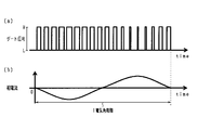
- FIG. 3 shows transitions of gate signals and phase currents for one phase when the PWM power generation control mode is executed.
- the gate signal indicates that H drives the upper arm switch on and drives the lower arm switch off, L drives the upper arm switch off and drives the lower arm switch on. Indicates to do.
- the phase current defines the direction of current flowing from the inverter 40 side to the stator winding side as positive.
- FIG. 4 is a block diagram of a synchronous rectification control mode performed by the MGECU 60.
- the configuration for performing the process shown in FIG. 4 in the MGECU 60 corresponds to the first control unit.
- a switch connected in anti-parallel to a current flowing in a period during which current is about to flow in a body diode connected in anti-parallel to a switch of inverter 40 during power generation of rotating electrical machine 30 Is turned on.
- a period in which current flows in the body diode is a period in which the generated voltage (counter electromotive voltage) of the stator winding exceeds the terminal voltage of the battery 20.
- the upper arm switch is turned on once in at least a part of a period in which the generated voltage of the stator winding exceeds the terminal voltage of the battery 20 in one electrical angle cycle. Thereby, the alternating current output from the stator winding is converted into a direct current.
- the synchronization generation unit 90 is a drive signal for turning on / off each switch SUp to SWn of the inverter 40 based on the electrical angle ⁇ e, the dead time DT of upper and lower arm switches of the inverter 40, and the command value ⁇ of voltage phase. Generate The drive signal generated by the synchronization generation unit 90 is a signal for turning on each of the upper arm switch and the lower arm switch once in one electrical angle cycle of each phase. The drive signals are out of phase by 120 ° in electrical angle in each phase.
- voltage deviation calculation unit 61, torque calculation unit 62, field command setting unit 80, field current control unit 81 and field generation unit 82 have the same configuration as shown in FIG. Therefore, even when one of the PWM power generation control mode and the synchronous rectification control mode is switched to the other, the continuity of control of the field current based on the command torque Trq * is maintained.
- FIG. 5 shows transitions of gate signals and phase currents for one phase when the synchronous rectification control mode is executed.
- 5 (a) and 5 (b) correspond to FIGS. 3 (a) and 3 (b).
- the rotational speed of the rotor 31 corresponding to the first commanded rotational speed Netgt1 is taken as a first rotor rotational speed Nm1.
- the first rotor rotational speed Nm1 is determined based on the transmission gear ratio from the output shaft 10a to the rotor 31 determined by the pulley ratio or the like and the first commanded rotational speed Netgt1. For example, when the first command rotational speed Netgt1 is 700 rpm and the transmission ratio is 3, the first rotor rotational speed Nm1 is 2100 rpm.
- the rotational speed of the rotor 31 corresponding to the second command rotational speed Netgt2 is taken as a second rotor rotational speed Nm2 (> Nm1).
- the second rotor rotational speed Nm2 is determined based on the transmission gear ratio from the output shaft 10a to the rotor 31 determined by the pulley ratio etc. and the second commanded rotational speed Netgt2.
- the rotation speed of the rotor 31 corresponding to the engine fluctuation amount ⁇ Ne is referred to as a rotor fluctuation amount ⁇ Nm.
- the rotor fluctuation amount ⁇ Nm is determined based on the transmission gear ratio from the output shaft 10a to the rotor 31 determined by the pulley ratio etc. and the engine fluctuation amount ⁇ Ne. For example, when the engine fluctuation amount ⁇ Ne is 80 rpm and the gear ratio is 3, the rotor fluctuation amount ⁇ Nm is 240 rpm.
- the high rotation side threshold value Nth2 is set to a value larger than the addition value of the first rotor rotation speed Nm1 and the rotor fluctuation amount ⁇ Nm, for example, set to a value larger than this addition value and not more than the second rotor rotation speed Nm2. It is done. In the present embodiment, the high rotation side threshold value Nth2 is set to the second rotor rotational speed Nm2.
- the low rotation side threshold Nth1 is set to a value smaller than the high rotation side threshold Nth2, for example, set to a value smaller than the high rotation side threshold Nth2 and equal to or more than the first rotor rotational speed Nm1.
- the low rotation side threshold value Nth1 is set to the first rotor rotation speed Nm1.
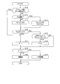
- FIG. 6 shows a procedure of control mode switching processing during idling operation. This process is repeatedly executed by MGECU 60, for example, at predetermined control cycles.
- step S10 it is determined by the engine ECU 11 whether idle up control is being performed. Whether or not the idle up control is being performed may be determined based on, for example, an external signal input from the engine ECU 11 via the upper ECU 12 and the communication line. Incidentally, based on an external signal input from the engine ECU 11 to the MGECU 60 without passing through the host ECU 12, it may be determined whether the idle-up control is being performed. Further, the MGECU 60 itself may determine whether or not the idle up control is being performed based on, for example, the rotation speed Nm of the rotor 31 regardless of external signals from the host ECU 12 and an external device of the engine ECU 11. In this case, if it is determined that the rotation speed Nm is controlled to the second rotor rotation speed Nm 2 based on the rotation speed Nm of the rotor 31, for example, the MGECU 60 determines that the idle up control is being executed. Good.
- step S11 it is determined whether the calculated fluctuation amount of the rotational speed Nm of the rotor 31 is smaller than a predetermined amount. In the process of step S11, it is determined whether or not the variation amount of the rotational speed of the output shaft 10a capable of transmitting power with the rotor 31 is small, and the high rotation side threshold Nth2 for determining switching of the control mode can be reduced. It is a process of determining whether there is any. That is, the high rotation threshold Nth2 is set to have a margin including the rotor fluctuation amount ⁇ Nm with respect to the low rotation threshold Nth1. Therefore, in the situation where the amount of fluctuation of the rotational speed of the output shaft 10a is small and the amount of rotor fluctuation ⁇ Nm is small, the high rotation side threshold value Nth2 can be reduced.
- the fluctuation amount of the rotational speed Nm is smaller than a predetermined amount.
- the elapsed time from the start of combustion in the combustion chamber of engine 10 has become equal to or longer than the determination time, or the temperature of engine 10 or its correlation value (for example, oil or cooling of engine 10) If it is determined that the detection value of the detection unit that detects the temperature of water has reached a predetermined temperature or higher, it may be determined that the warm-up is completed.
- the fluctuation amount of the rotational speed Nm is smaller than a predetermined amount from the engine rotational speed Ner calculated by the speed calculation unit based on the output signal of the crank angle sensor or the like.
- step S11 If it is determined in step S11 that the fluctuation amount of the rotational speed Nm is equal to or more than the predetermined amount, the process proceeds to step S12, and the high rotation side threshold Nth2 is set to the first threshold N ⁇ .
- step S11 when it is determined in step S11 that the fluctuation amount of the rotational speed Nm is smaller than the predetermined amount, the process proceeds to step S13 and the high rotation side threshold Nth2 is a value larger than the low rotation side threshold Nth1 described later And it sets to 2nd threshold value N beta smaller than 1st threshold value N alpha. According to the process of step S15, the opportunity to execute the synchronous rectification control mode can be increased, and the switching loss generated in the inverter 40 can be reduced.
- step S14 After completion of the processes of steps S12 and S13, the process proceeds to step S14, and it is determined whether the calculated rotational speed Nm of the rotor 31 is equal to or higher than the high rotation threshold Nth2. If it is determined in step S14 that the rotation speed Nm is lower than the high rotation threshold Nth2, the process proceeds to step S15, and it is determined whether the calculated rotation speed Nm of the rotor 31 is less than or equal to the low rotation threshold Nth1. Do.
- step S15 If it is determined in step S15 that the rotational speed Nm is equal to or lower than the low rotation threshold value Nth1, the process proceeds to step S16, and the determination flag F is set to 0.
- the determination flag F instructs execution of the PWM power generation control mode by 0, and instructs execution of the synchronous rectification control mode by 1.
- the initial value of the determination flag F is 0.
- step S14 If it is determined in step S14 that the rotational speed Nm is equal to or higher than the high rotation threshold Nth2, the process proceeds to step S17, and the determination flag F is set to 1. If it is determined in step S15 that the rotational speed Nm is higher than the low rotation threshold Nth1, the control mode currently being executed is continuously executed.
- step S18 it is determined whether the determination flag F is one. When it is determined in step S18 that the determination flag F is 0, the process proceeds to step S19, and the execution of the PWM power generation control mode shown in FIG. 2 is instructed. On the other hand, when it is determined in step S18 that the determination flag F is 1, the process proceeds to step S20, and the execution of the synchronous rectification control mode shown in FIG. 4 is instructed.
- the processing of steps S14 to S20 corresponds to a switching unit that switches the control mode.
- step S10 If it is determined in step S10 that idle up control is being performed, the process proceeds to step S17. As a result, the determination flag F is set to 1. As a result, regardless of the rotational speed Nm of the rotor 31, the execution of the synchronous rectification control mode is then instructed in step S20. Therefore, the switching loss generated in inverter 40 can be reduced as compared to the case where the PWM power generation control mode is implemented.
- FIG. 7 shows a mode of switching from the PWM power generation control mode to the synchronous rectification control mode
- FIG. 8 shows a mode of switching from the synchronous rectification control mode to the PWM power generation control mode.
- 7 (a) and 8 (a) show the transition of the rotational speed Nm of the rotor 31 calculated by the MGECU 60
- FIGS. 7 (b) and 8 (b) show the transition of the control method.
- the example shown in FIG. 7 is an example in which the control mode is switched when the normal control is performed.
- the example shown in FIG. 8 is an example in which the control mode is switched after it is determined that the rotational speed Nm has become equal to or lower than the low rotation side threshold Nth1 after switching from idle up control to normal control, for example.
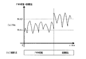
- FIG. 9 shows the switching mode of the control mode in the comparative example.
- the synchronous rectification control mode is executed, and it is determined that the rotation speed Nm is equal to or less than the speed threshold Nthc
- the PWM power generation control mode is executed when it is turned off.
- FIGS. 9 (a) and 9 (b) correspond to FIGS. 7 (a) and 7 (b)
- FIG. 9 (c) shows the main components of the inverter 40 that occur when each control mode is executed. Shows the transition of the frequency of the operation sound.
- FIG. 9 (d) shows the transition of the torque of the rotary electric machine 30, and
- FIG. 9 (e) shows the transition of the output current flowing from the inverter 40 to the battery 20 as power is generated.
- the switching frequency of the switch of the inverter 40 when the synchronous rectification control mode is implemented is lower than the switching frequency of the switch of the inverter 40 when the PWM power generation control mode is implemented. Therefore, as shown in FIG. 9C, the frequency of the main operation noise generated when the synchronous rectification control mode is implemented is the frequency of the main operation noise generated when the PWM power generation control mode is implemented. It is lower than the frequency.
- the control mode is frequently switched, the frequency of the main operation noise is frequently switched, and the NVH characteristics of the rotary electric machine 21 deteriorate.
- hysteresis is set to the switching threshold values Nth1 and Nth2 of the PWM control mode and the synchronous rectification control mode. Therefore, even when the rotation speed Nm of the rotor 31 fluctuates, frequent switching of the control mode can be suppressed. Thereby, the NVH characteristics and reliability of the rotary electric machine 21 can be improved.
- FIG. 10 shows a block diagram of the field current control unit 81 of the present embodiment.
- FIG. 10 also shows a transfer function obtained by modeling the field winding 32.
- FIG. 10 shows a transfer function determined by the resistance R and the inductance L of the field winding 32 as an example of this transfer function.
- the field current control unit 81 includes a smoothing unit 81a, a deviation calculation unit 81b, and a command value calculation unit 81c.
- the smoothing unit 81a performs low-pass filter processing on the field current Ifr, and outputs it as a filtered current Iff.
- a first-order lag type is used as the smoothing section 81a.
- the deviation calculating unit 81a calculates a field current deviation ⁇ If as a value obtained by subtracting the filtered current Iff from the field command current If *.
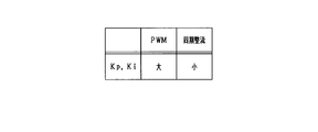
- field command setting unit 80 generates field command current If * when synchronous rectification control mode is selected, or field command current If * when PWM power generation control mode is selected. Also set large.
- Command value calculation unit 81c calculates field command voltage Vf * as an operation amount for feedback control of field current deviation ⁇ If to zero.
- the feedback control used by the field current control unit 81 is proportional integral control.
- the command value calculation unit 81c selects the proportional and integral gains Kp and Ki when the PWM power generation control mode is selected and the synchronous rectification control mode is selected.
- the proportional and integral gains Kp and Ki are set larger.
- the command value calculation unit 81c corresponds to a gain setting unit.
- the setting of the gain described above is performed to suppress the decrease in responsiveness of the field current Ifr (specifically, the filtered current Iff) in the PWM control mode. That is, in the present embodiment, the field command current If * when the PWM power generation control mode is selected is smaller than the field command current If * when the synchronous rectification control mode is selected. Therefore, the field current deviation ⁇ If in the case where the PWM power generation control mode is selected tends to be smaller than the field current deviation ⁇ If in the case where the synchronous rectification control mode is selected.
- the command value calculation unit 81c performs proportional control when the PWM power generation control mode is selected, and integral control when the synchronous rectification control mode is selected. Set larger than gains Kp and Ki.
- the feedback control in the field current control unit 81 may include differential control.
- the differential gain in the case where the PWM power generation control mode is selected may be set larger than the differential gain in the case where the synchronous rectification control mode is selected.
- the second threshold value N ⁇ may be set to a smaller value as the fluctuation amount of the rotational speed Nm is smaller.
- the synchronous rectification control mode and the PWM power generation control mode are switched.
- the present invention is not limited to this.
- the synchronous rectification control mode and the overmodulation control mode having a switching frequency higher than that of the mode may be switched, or the overmodulation control mode and the PWM power generation control mode may be switched.
- the present disclosure can be applied even when the rotating electrical machine is driven as a motor.
- the rectangular wave control mode corresponding to the switching control of the first control unit and the PWM control mode corresponding to the switching control of the second control unit are switched.
- the rectangular wave control mode is a mode in which the upper arm switch and the lower arm switch are each turned on once in one electrical angle cycle of each phase of the inverter 40.
- the field energizing circuit is not limited to the full bridge circuit, and may be, for example, a half bridge circuit.
- the switch used in the inverter and the field energizing circuit is not limited to the N channel MOSFET.
- the control amount of the rotating electrical machine is not limited to the torque, and may be, for example, the generated power of the rotating electrical machine 30.
- the rotating electric machine is not limited to star-connected ones, and may be ⁇ -connected, for example. Further, the rotating electrical machine is not limited to a winding field type including a field winding, and may be, for example, a permanent magnet type including a permanent magnet on a rotor.
Abstract
A control device (60) is used in a control system provided with: a rotary electric machine (30) having stator windings (34U to 34W); and an inverter (40) that has switches (SUp-SWn) and drives the switches to transmit electric power between a DC power supply (20) and the stator windings. The control device is provided with: a first control unit that performs switching control of the switches; a second control unit that performs switching control of the switches at a switching frequency that differs from the switching frequency of the switches by the first control unit; and a switching unit that, if it is determined that the rotational speed of the rotary electric machine is at or above a high rotation side threshold (Nth2), switches from switching control by the second control unit to switching control by the first control unit, and if it is determined that the rotational speed of the rotary electric machine is at or below a low rotation side threshold (Nth1), which is smaller than the high rotation side threshold, switches from switching control by the first control unit to switching control by the second control unit.
Description
本出願は、2017年10月31日に出願された日本出願番号2017-210294号に基づくもので、ここにその記載内容を援用する。
This application is based on Japanese Patent Application No. 2017-210294 filed Oct. 31, 2017, the contents of which are incorporated herein by reference.
本開示は、回転電機の制御装置に関する。
The present disclosure relates to a control device of a rotating electrical machine.
従来、特許文献1に見られるように、回転電機のステータ巻線に流す電流を制御し、回転電機の界磁巻線に流す界磁電流を制御する制御装置が知られている。制御装置は、回転電機の回転速度が所定値以下の場合、界磁電流を制御するとともに、PWM制御された電流をステータ巻線に流して回転電機に発電させるPWM制御モードを実施する。制御装置は、回転電機の回転速度が所定値を超える場合、界磁電流の制御により回転電機に発電させる界磁制御モードを実施する。
Conventionally, as seen in Patent Document 1, there is known a control device that controls a current flowing through a stator winding of a rotating electrical machine and controls a field current flowing through a field winding of the rotating electrical machine. The control device controls the field current when the rotational speed of the rotating electrical machine is equal to or less than a predetermined value, and implements a PWM control mode of causing the rotating electrical machine to generate power by causing a PWM controlled current to flow through the stator winding. When the rotational speed of the rotating electrical machine exceeds a predetermined value, the control device implements a field control mode in which the rotating electrical machine is caused to generate power by control of the field current.
PWM制御モードでは、直流電源とステータ巻線との間の電力伝達を行うインバータのスイッチが駆動されることにより、ステータ巻線に流れる電流が制御される。界磁制御モードが実施される場合におけるスイッチのスイッチング周波数は、PWM制御モードが実施される場合におけるスイッチのスイッチング周波数よりも低い。このため、界磁制御モードが実施される場合に発生する主な動作音の周波数は、PWM制御モードが実施される場合に発生する主な動作音の周波数よりも低い。
In the PWM control mode, a switch of an inverter for transferring power between the DC power supply and the stator winding is driven to control the current flowing through the stator winding. The switching frequency of the switch when the field control mode is implemented is lower than the switching frequency of the switch when the PWM control mode is implemented. Therefore, the frequency of the main operation noise generated when the field control mode is implemented is lower than the frequency of the main operation noise generated when the PWM control mode is implemented.
ここで、回転電機の回転速度が所定値近傍で変動すると、PWM制御モード及び界磁制御モードのうち、一方の制御モードから他方の制御モードへと頻繁に切り替えられる事態が発生し得る。制御モードが頻繁に切り替えられると、主な動作音の周波数が頻繁に切り替わり、NVH特性が悪化する懸念がある。
Here, if the rotational speed of the rotating electrical machine fluctuates near a predetermined value, a situation may occur in which the control mode of one of the PWM control mode and the field control mode is frequently switched to the other control mode. When the control mode is frequently switched, the frequency of the main operation noise is frequently switched, which may deteriorate the NVH characteristics.
なお、PWM制御モード及び界磁制御モードのうち、一方の制御モードから他方の制御モードへの切り替えを実施する制御装置に限らず、スイッチング周波数が異なる2つの制御モードの切り替えを実施する制御装置であれば、上述した問題は同様に生じ得る。
Of the PWM control mode and the field control mode, the control device is not limited to the control device that performs switching from one control mode to the other control mode, but may be any control device that performs switching of two control modes having different switching frequencies. The problems described above can arise as well.
本開示は、回転電機の駆動制御におけるNVH特性を改善できる回転電機の制御装置を提供することを主たる目的とする。
The present disclosure has as its main object to provide a control device of a rotary electric machine capable of improving the NVH characteristic in drive control of the rotary electric machine.
本開示は、ステータ巻線を有する回転電機と、スイッチを有し、前記スイッチを駆動することにより直流電源と前記ステータ巻線との間の電力伝達を行うインバータと、を備える制御システムに適用される回転電機の制御装置である。本開示は、前記スイッチをスイッチング制御する第1制御部と、前記第1制御部における前記スイッチのスイッチング周波数とは異なるスイッチング周波数で前記スイッチをスイッチング制御する第2制御部と、前記回転電機の回転速度が高回転側閾値以上になったと判定した場合、前記第2制御部によるスイッチング制御から前記第1制御部によるスイッチング制御に切り替え、前記回転電機の回転速度が、前記高回転側閾値よりも小さい低回転側閾値以下になったと判定した場合、前記第1制御部によるスイッチング制御から前記第2制御部によるスイッチング制御に切り替える切替部と、を備える。
The present disclosure is applied to a control system including a rotating electrical machine having a stator winding, and an inverter having a switch and performing power transmission between a DC power supply and the stator winding by driving the switch. Control device for a rotating electric machine. The present disclosure relates to a first control unit that performs switching control of the switch, a second control unit that performs switching control of the switch at a switching frequency different from a switching frequency of the switch in the first control unit, and rotation of the rotating electrical machine When it is determined that the speed is equal to or higher than the high rotation threshold, switching is performed from the switching control by the second control unit to the switching control by the first control unit, and the rotational speed of the rotating electrical machine is smaller than the high rotation threshold And a switching unit configured to switch the switching control by the first control unit to the switching control by the second control unit when it is determined that the low rotation side threshold value or less is reached.
本開示では、第2制御部におけるインバータのスイッチのスイッチング周波数と、第1制御部におけるスイッチのスイッチング周波数とが異なっている。この構成を前提として、本開示では、回転電機の回転速度が高回転側閾値以上になったと判定された場合、第2制御部によるスイッチング制御から第1制御部によるスイッチング制御に切り替えられる。一方、回転電機の回転速度が、高回転側閾値よりも小さい低回転側閾値以下になったと判定された場合、第1制御部によるスイッチング制御から前2制御部によるスイッチング制御に切り替えられる。このため、回転電機の回転速度が変動する場合であっても、第1制御部によるスイッチング制御及び第2制御部によるスイッチング制御のうち、一方から他方への頻繁な切り替えを抑制することができる。これにより、回転電機の駆動制御におけるNVH特性を改善することができる。
In the present disclosure, the switching frequency of the switch of the inverter in the second control unit and the switching frequency of the switch in the first control unit are different. Based on this configuration, in the present disclosure, when it is determined that the rotational speed of the rotating electrical machine has become equal to or higher than the high rotation threshold, switching control from the switching control by the second control unit to switching control by the first control unit is performed. On the other hand, when it is determined that the rotational speed of the rotating electrical machine has become equal to or lower than the low rotation threshold lower than the high rotation threshold, the switching control by the first control unit is switched to the switching control by the front two control units. For this reason, even when the rotational speed of the rotating electrical machine fluctuates, frequent switching from one to the other of the switching control by the first control unit and the switching control by the second control unit can be suppressed. Thereby, it is possible to improve the NVH characteristics in the drive control of the rotary electric machine.
本開示についての上記目的およびその他の目的、特徴や利点は、添付の図面を参照しながら下記の詳細な記述により、より明確になる。その図面は、
図1は、第1実施形態に係る車載制御システムの全体構成図であり、
図2は、PWM発電制御モードのブロック図であり、
図3は、PWM発電制御モード時におけるインバータのスイッチの駆動態様及び相電流の推移を示すタイムチャートであり、
図4は、同期整流制御モードのブロック図であり、
図5は、同期整流制御モード時におけるインバータのスイッチの駆動態様及び相電流の推移を示すタイムチャートであり、
図6は、制御モードの切替処理の手順を示すフローチャートであり、
図7は、PWM発電制御モードから同期整流制御モードへの切り替え態様を示すタイムチャートであり、
図8は、同期整流制御モードからPWM発電制御モードへの切り替え態様を示すタイムチャートであり、
図9は、比較例に係る制御モードの切り替え態様を示すタイムチャートであり、
図10は、第2実施形態に係る界磁電流制御部における処理等を示す図であり、
図11は、フィードバックゲインの設定方法を示す図である。
The above object and other objects, features and advantages of the present disclosure will become more apparent from the following detailed description with reference to the attached drawings. The drawing is
FIG. 1 is an overall configuration diagram of the in-vehicle control system according to the first embodiment, FIG. 2 is a block diagram of a PWM generation control mode, FIG. 3 is a time chart showing the drive mode of the switch of the inverter and the transition of the phase current in the PWM power generation control mode, Fig. 4 is a block diagram of the synchronous rectification control mode, FIG. 5 is a time chart showing the drive mode of the switch of the inverter and the transition of the phase current in the synchronous rectification control mode, FIG. 6 is a flowchart showing the procedure of control mode switching processing; FIG. 7 is a time chart showing a switching mode from the PWM generation control mode to the synchronous rectification control mode, FIG. 8 is a time chart showing a switching mode from the synchronous rectification control mode to the PWM power generation control mode, FIG. 9 is a time chart showing a switching mode of control modes according to a comparative example; FIG. 10 is a diagram showing processing and the like in the field current control unit according to the second embodiment, FIG. 11 is a diagram showing a method of setting a feedback gain.
<第1実施形態>
以下、本開示に係る制御装置を車両に搭載した第1実施形態について、図面を参照しつつ説明する。 First Embodiment
Hereinafter, a first embodiment in which a control device according to the present disclosure is mounted on a vehicle will be described with reference to the drawings.
以下、本開示に係る制御装置を車両に搭載した第1実施形態について、図面を参照しつつ説明する。 First Embodiment
Hereinafter, a first embodiment in which a control device according to the present disclosure is mounted on a vehicle will be described with reference to the drawings.
図1に示すように、車両は、車載主機としてのエンジン10を備えている。エンジン10は、燃料噴射弁等を備え、燃料噴射弁から噴射されたガソリン又は軽油等の燃料の燃焼により動力を発生する。発生した動力は、エンジン10の出力軸10aから出力される。
As shown in FIG. 1, the vehicle is provided with an engine 10 as a vehicle-mounted main machine. The engine 10 includes a fuel injection valve and the like, and generates power by combustion of fuel such as gasoline or light oil injected from the fuel injection valve. The generated power is output from the output shaft 10 a of the engine 10.
車両は、直流電源としてのバッテリ20と、回転電機装置21とを備えている。バッテリ20は、例えば、定格電圧が12Vの鉛蓄電池である。回転電機装置21は、コンデンサ22、交流駆動される回転電機30、インバータ40、界磁通電回路41、及び回転電機30を制御する制御装置であるMGECU60を備えている。本実施形態では、回転電機30として、巻線界磁型の同期機が用いられている。また、本実施形態において、MGECU60は、回転電機30が電動機兼発電機であるISG(Integrated Starter Generator)として機能するように回転電機30を制御する。回転電機装置21は、回転電機、インバータ40、界磁通電回路41及びMGECU60を備える機電一体型駆動装置である。
The vehicle includes a battery 20 as a direct current power supply and a rotating electrical machine 21. The battery 20 is, for example, a lead storage battery with a rated voltage of 12V. The rotary electric machine 21 includes a capacitor 22, a rotary electric machine 30 driven by alternating current, an inverter 40, a field energizing circuit 41, and an MGECU 60 which is a control device for controlling the rotary electric machine 30. In the present embodiment, a winding field type synchronous machine is used as the rotating electrical machine 30. Further, in the present embodiment, the MGECU 60 controls the rotating electrical machine 30 such that the rotating electrical machine 30 functions as an ISG (Integrated Starter Generator) which is a motor and a generator. The rotating electrical machine device 21 is a mechanical-electrical integrated drive device including a rotating electrical machine, an inverter 40, a field energizing circuit 41, and an MGECU 60.
回転電機30は、ロータ31を備えている。ロータ31は、界磁巻線32を備えている。ロータ31の回転軸は、図示しないプーリ等を介してエンジン10の出力軸10aと動力伝達が可能とされている。回転電機30が発電機として駆動される場合、出力軸10aから供給される回転動力によってロータ31が回転し、回転電機30が発電する。回転電機30の発電電力により、バッテリ20が充電される。一方、回転電機30が電動機として駆動される場合、ロータ31の回転に伴って出力軸10aが回転し、出力軸10aに回転力が付与される。これにより、例えば車両の走行をアシストすることができる。なお、出力軸10aには、変速装置等を介して車両の駆動輪が接続されている。
The rotating electrical machine 30 includes a rotor 31. The rotor 31 comprises a field winding 32. The rotation shaft of the rotor 31 can transmit power to the output shaft 10a of the engine 10 via a pulley or the like (not shown). When the rotary electric machine 30 is driven as a generator, the rotor 31 is rotated by the rotational power supplied from the output shaft 10a, and the rotary electric machine 30 generates electric power. The battery 20 is charged by the power generated by the rotating electrical machine 30. On the other hand, when the rotary electric machine 30 is driven as an electric motor, the output shaft 10a rotates with the rotation of the rotor 31, and a rotational force is applied to the output shaft 10a. Thereby, for example, traveling of the vehicle can be assisted. A driving wheel of the vehicle is connected to the output shaft 10a via a transmission or the like.
回転電機30は、ステータ33を備えている。ステータ33は、ステータ巻線を備えている。ステータ巻線は、電気角で互いに120°ずれた状態で配置されたU,V,W相巻線34U,34V,34Wを含む。
The rotating electrical machine 30 is provided with a stator 33. The stator 33 is provided with a stator winding. The stator windings include U, V, W phase windings 34U, 34V, 34W which are arranged 120 degrees apart from each other in electrical angle.
インバータ40は、U,V,W相上アームスイッチSUp,SVp,SWpと、U,V,W相下アームスイッチSUn,SVn,SWnとの直列接続体を備えている。U,V,W相上アームスイッチSUp,SVp,SWpと、U,V,W相下アームスイッチSUn,SVn,SWnとの接続点には、U,V,W相巻線34U,34V,34Wの第1端が接続されている。U,V,W相巻線34U,34V,34Wの第2端は、中性点で接続されている。すなわち、本実施形態において、U,V,W相巻線34U,34V,34Wは、星形結線されている。
The inverter 40 includes a series connection of U, V, W upper arm switches SUp, SVp, SWp and U, V, W lower arm switches SUn, SVn, SWn. U, V, W- phase windings 34U, 34V, 34W are connected to the connection points of U, V, W-phase upper arm switches SUp, SVp, SWp and U, V, W-phase lower arm switches SUn, SVn, SWn. The first end of is connected. The second ends of the U, V, W phase windings 34U, 34V, 34W are connected at a neutral point. That is, in the present embodiment, the U, V, W phase windings 34U, 34V, 34W are star-connected.
なお、本実施形態において、各スイッチSUp~SWnは、NチャネルMOSFETである。NチャネルMOSFETがオン駆動される場合、高電位側端子であるドレイン及び低電位側端子であるソースの間の電流の流通が許可される。一方、NチャネルMOSFETがオフ駆動される場合、ドレイン及びソース間の電流の流通が阻止される。各スイッチSUp,SVp,SWp,SUn,SVn,SWnには、各ボディダイオードDUp,DVp,DWp,DUn,DVn,DWnが逆並列に接続されている。
In the present embodiment, the switches SUp to SWn are N-channel MOSFETs. When the N-channel MOSFET is turned on, the flow of current between the drain as the high potential side terminal and the source as the low potential side terminal is permitted. On the other hand, when the N-channel MOSFET is driven off, current flow between the drain and the source is blocked. Respective body diodes DUp, DVp, DWp, DUn, DVn, DWn are connected in anti-parallel to the switches SUp, SVp, SWp, SUn, SVn, SWn.
U,V,W相上アームスイッチSUp,SVp,SWpのドレインには、高電位側電気経路Lpを介してバッテリ20の正極端子が接続されている。U,V,W相下アームスイッチSUn,SVn,SWnのソースには、低電位側電気経路Lnを介してバッテリ20の負極端子が接続されている。各電気経路Lp,Lnは、バスバー等の導電部材である。各上アームスイッチSUp,SVp,SWpのドレインと高電位側電気経路Lpとの接続点のうちバッテリ20の正極端子に最も近い接続点と、バッテリ20の正極端子とを接続する高電位側電気経路Lpには、コンデンサ22の高電位側端子が接続されている。各下アームスイッチSUn,SVn,SWnのソースと低電位側電気経路Lnとの接続点のうちバッテリ20の負極端子に最も近い接続点と、バッテリ20の負極端子とを接続する低電位側電気経路Lnには、コンデンサ22の低電位側端子が接続されている。
The positive terminal of the battery 20 is connected to the drains of the U, V, W-phase upper arm switches SUp, SVp, SWp via the high potential side electric path Lp. The negative terminal of the battery 20 is connected to the sources of the U, V, W-phase lower arm switches SUn, SVn, SWn via the low potential side electric path Ln. Each of the electric paths Lp and Ln is a conductive member such as a bus bar. A high potential side electric path connecting a positive connection terminal of the battery 20 and a connection point closest to the positive electrode terminal of the battery 20 among the connection points of the drains of the upper arm switches SUp, SVp, SWp and the high potential side electric path Lp The high potential side terminal of the capacitor 22 is connected to Lp. A low potential side electric path connecting a connection point closest to the negative terminal of the battery 20 among the connection points of the sources of the lower arm switches SUn, SVn, SWn and the low potential side electric path Ln to the negative terminal of the battery 20 The low potential side terminal of the capacitor 22 is connected to Ln.
界磁通電回路41は、フルブリッジ回路であり、第1上アームスイッチSH1及び第1下アームスイッチSL1の直列接続体と、第2上アームスイッチSH2及び第2下アームスイッチSL2の直列接続体とを備えている。第1上アームスイッチSH1と第1下アームスイッチSL1との接続点には、図示しないブラシを介して界磁巻線32の第1端が接続されている。第2上アームスイッチSH2と第2下アームスイッチSL2との接続点には、図示しないブラシを介して界磁巻線32の第2端が接続されている。なお、本実施形態において、各アームスイッチSH1,SL1,SH2,SL2は、NチャネルMOSFETである。各スイッチSH1,SL1,SH2,SL2には、各ボディダイオードDH1,DL1,DH2,DL2が逆並列に接続されている。
Field energizing circuit 41 is a full bridge circuit, and includes a series connection of a first upper arm switch SH1 and a first lower arm switch SL1, and a series connection of a second upper arm switch SH2 and a second lower arm switch SL2. Is equipped. A first end of the field winding 32 is connected to a connection point between the first upper arm switch SH1 and the first lower arm switch SL1 via a brush (not shown). A second end of the field winding 32 is connected to a connection point between the second upper arm switch SH2 and the second lower arm switch SL2 via a brush (not shown). In the present embodiment, each arm switch SH1, SL1, SH2, and SL2 is an N-channel MOSFET. Body diodes DH1, DL1, DH2, and DL2 are connected in anti-parallel to the switches SH1, SL1, SH2, and SL2.
第1,第2上アームスイッチSH1,SH2のドレインには、高電位側電気経路Lpのうちコンデンサ22の高電位側端子との接続点よりもインバータ40側が接続されている。第1,第2下アームスイッチSL1,SL2のソースには、低電位側電気経路Lnのうちコンデンサ22の低電位側端子との接続点よりもインバータ40側が接続されている。
The drains of the first and second upper arm switches SH1 and SH2 are connected to the inverter 40 side of the high potential side electric path Lp rather than the connection point with the high potential side terminal of the capacitor 22. The inverter 40 side is connected to the sources of the first and second lower arm switches SL1 and SL2 rather than the connection point with the low potential side terminal of the capacitor 22 in the low potential side electrical path Ln.
回転電機装置21は、電圧検出部50、相電流検出部51、界磁電流検出部52及び角度検出部53を備えている。電圧検出部50は、コンデンサ22の端子電圧を電源電圧VDCとして検出する。相電流検出部51は、U,V,W相巻線34U,34V,34Wに流れる相電流を検出する。界磁電流検出部52は、界磁巻線32に流れる界磁電流を検出する。角度検出部53は、ロータ31の回転角に応じた信号である角度信号を出力する。各検出部50~53の出力信号は、MGECU60に入力される。
The rotating electrical machine apparatus 21 includes a voltage detection unit 50, a phase current detection unit 51, a field current detection unit 52, and an angle detection unit 53. The voltage detection unit 50 detects the terminal voltage of the capacitor 22 as the power supply voltage VDC. The phase current detection unit 51 detects phase currents flowing in the U, V, W phase windings 34U, 34V, 34W. The field current detection unit 52 detects a field current flowing through the field winding 32. The angle detection unit 53 outputs an angle signal which is a signal corresponding to the rotation angle of the rotor 31. The output signals of the detection units 50 to 53 are input to the MGECU 60.
なお、MGECU60の各機能の一部又は全部は、例えば、1つ又は複数の集積回路等によりハードウェア的に構成されていてもよい。また、MGECU60の各機能は、例えば、非遷移的実体的記録媒体に記録されたソフトウェア及びそれを実行するコンピュータによって構成されていてもよい。
Note that part or all of the functions of MGECU 60 may be configured as hardware by, for example, one or more integrated circuits. In addition, each function of MGECU 60 may be configured by, for example, software recorded in a non-transitional tangible storage medium and a computer that executes the software.
車両は、エンジン10の燃焼制御を行う制御装置であるエンジンECU11と、車両の制御を統括する上位の制御装置である上位ECU12とを備えている。MGECU60、エンジンECU11及び上位ECU12は、CAN等の通信線により情報のやり取りが可能とされている。
The vehicle includes an engine ECU 11 that is a control device that performs combustion control of the engine 10, and a host ECU 12 that is a high-order control device that controls the control of the vehicle. The MGECU 60, the engine ECU 11, and the host ECU 12 can exchange information via communication lines such as CAN.
エンジンECU11は、エンジン10のアイドリング運転中の燃焼制御として、通常時制御と、アイドルアップ制御とを行う。通常時制御は、出力軸10aの回転速度であるエンジン回転速度Nerを第1指令回転速度Netgt1に制御するための燃焼制御である。アイドルアップ制御は、エンジン回転速度Nerを、第1指令回転速度Netgt1よりも高い第2指令回転速度Netgt2に制御するための燃焼制御である。各指令回転速度Netgt1,Netgt2は、エンジン10の冷却水の温度等に応じて可変設定される。エンジンECU11は、所定の条件が成立したと判定した場合、通常時制御からアイドルアップ制御に切り替える。所定の条件は、例えば、出力軸10aの動力により駆動される車載機器の消費動力が所定動力以上になったとの条件である。この場合の車載機器には、回転電機30も含まれる。
The engine ECU 11 performs normal control and idle up control as combustion control during idling operation of the engine 10. The normal control is combustion control for controlling the engine rotational speed Ner, which is the rotational speed of the output shaft 10a, to the first command rotational speed Netgt1. The idle up control is combustion control for controlling the engine rotational speed Ner to a second command rotational speed Netgt2 higher than the first command rotational speed Netgt1. Respective commanded rotational speeds Netgt1 and Netgt2 are variably set according to the temperature of the coolant of the engine 10 and the like. When it is determined that the predetermined condition is satisfied, the engine ECU 11 switches from the normal control to the idle up control. The predetermined condition is, for example, a condition that the consumption power of the on-vehicle device driven by the power of the output shaft 10a becomes equal to or higher than the predetermined power. The on-vehicle apparatus in this case also includes the rotating electrical machine 30.
MGECU60は、インバータ40及び界磁通電回路41を構成する各スイッチの駆動信号を生成する。
MGECU 60 generates a drive signal of each switch constituting inverter 40 and field energizing circuit 41.
まず、インバータ40について説明する。MGECU60は、角度検出部53の角度信号を取得し、取得した角度信号に基づいて、インバータ40を構成する各スイッチSUp~SWnをオンオフする駆動信号を生成する。詳しくは、MGECU60は、回転電機30を電動機として駆動させる場合、バッテリ20から出力された直流電力を交流電力に変換してU,V,W相巻線34U,34V,34Wに供給すべく、各アームスイッチSUp~SWnをオンオフする駆動信号を生成し、生成した駆動信号を各アームスイッチSUp~SWnのゲートに供給する。一方、MGECU60は、回転電機30を発電機として駆動させる場合、U,V,W相巻線34U,34V,34Wから出力された交流電力を直流電力に変換してバッテリ20に供給すべく、各アームスイッチSUp~SWnをオンオフする駆動信号を生成する。
First, the inverter 40 will be described. The MGECU 60 acquires the angle signal of the angle detection unit 53, and generates a drive signal to turn on and off the switches SUp to SWn constituting the inverter 40 based on the acquired angle signal. Specifically, when driving rotary electric machine 30 as an electric motor, MGECU 60 converts DC power output from battery 20 into AC power and supplies it to U, V, W phase windings 34U, 34V, 34W. A drive signal for turning on / off the arm switches SUp to SWn is generated, and the generated drive signal is supplied to the gate of each of the arm switches SUp to SWn. On the other hand, when driving rotary electric machine 30 as a generator, MGECU 60 converts AC power output from U, V, W phase windings 34U, 34V, 34W into DC power and supplies it to battery 20. A drive signal for turning on and off the arm switches SUp to SWn is generated.
続いて、界磁通電回路41について説明する。MGECU60は、界磁巻線32を励磁すべく、界磁通電回路41を構成する各スイッチをオンオフする。詳しくは、MGECU60は、第1状態と第2状態とが交互に出現するように各スイッチをオンオフする。第1状態は、第1上アームスイッチSH1と第2下アームスイッチSL2とがオンされて、かつ、第2上アームスイッチSH2と第1下アームスイッチSL1とがオフされている状態である。第2状態は、第1上アームスイッチSH1と第2下アームスイッチSL2とがオフされて、かつ、第2上アームスイッチSH2と第1下アームスイッチSL1とがオンされている状態である。
Subsequently, the field energization circuit 41 will be described. In order to excite field winding 32, MGECU 60 turns on / off each switch constituting field energizing circuit 41. Specifically, MGECU 60 turns each switch on and off so that the first state and the second state appear alternately. In the first state, the first upper arm switch SH1 and the second lower arm switch SL2 are turned on, and the second upper arm switch SH2 and the first lower arm switch SL1 are turned off. In the second state, the first upper arm switch SH1 and the second lower arm switch SL2 are turned off, and the second upper arm switch SH2 and the first lower arm switch SL1 are turned on.
MGECU60は、角度検出部53の角度信号に基づいて、回転電機30の電気角θeと、ロータ31の回転速度Nmとを算出する。
The MGECU 60 calculates the electrical angle θe of the rotary electric machine 30 and the rotational speed Nm of the rotor 31 based on the angle signal of the angle detection unit 53.
以下、本実施形態では、回転電機30を発電機として駆動させる場合について説明する。図2に、MGECU60が行うPWM発電制御モードのブロック図を示す。なお、本実施形態において、MGECU60のうち、図2に示す処理を行う構成が第2制御部に相当する。
Hereinafter, in the present embodiment, a case where the rotary electric machine 30 is driven as a generator will be described. FIG. 2 shows a block diagram of a PWM power generation control mode performed by MGECU 60. As shown in FIG. In the present embodiment, the configuration for performing the process shown in FIG. 2 in the MGECU 60 corresponds to the second control unit.
電圧偏差算出部61は、指令発電電圧VD*から、電圧検出部50により検出された電源電圧VDCを減算することにより、電圧偏差ΔVを算出する。指令発電電圧VD*は、インバータ40からバッテリ20に出力する直流電圧の指令値である。指令発電電圧VD*は、例えば、上位ECU12からMGECU60へと入力される。
Voltage deviation calculation unit 61 calculates voltage deviation ΔV by subtracting power supply voltage VDC detected by voltage detection unit 50 from command power generation voltage VD *. The command power generation voltage VD * is a command value of the DC voltage output from the inverter 40 to the battery 20. The command power generation voltage VD * is input from, for example, the host ECU 12 to the MGECU 60.
トルク算出部62は、電圧偏差ΔVを0にフィードバック制御するための操作量として、回転電機30の制御量の指令値を算出する。本実施形態において、制御量はトルクであり、その指令値は指令トルクTrq*である。また、本実施形態において、トルク算出部62で用いられるフィードバック制御は、比例積分制御である。なお、フィードバック制御としては、比例積分制御に限らず、例えば比例積分微分制御であってもよい。
The torque calculation unit 62 calculates a command value of the control amount of the rotary electric machine 30 as an operation amount for feedback control of the voltage deviation ΔV to zero. In the present embodiment, the control amount is torque, and the command value thereof is command torque Trq *. Further, in the present embodiment, the feedback control used by the torque calculation unit 62 is proportional integral control. The feedback control is not limited to proportional integral control, and may be, for example, proportional integral derivative control.
2相変換部70は、相電流検出部51により検出された相電流及び電気角θeに基づいて、回転電機30の3相固定座標系におけるU,V,W相電流IU,IV,IWを、2相回転座標系であるdq座標系におけるd,q軸電流Idr,Iqrに変換する。
The two-phase conversion unit 70 generates U, V, W phase currents IU, IV, IW in the three-phase fixed coordinate system of the rotary electric machine 30 based on the phase current and the electrical angle θe detected by the phase current detection unit 51. It converts into d, q axis current Idr, Iqr in the dq coordinate system which is a two-phase rotational coordinate system.
d軸指令設定部71は、指令トルクTrq*に基づいて、回転電機30のトルクを指令トルクTrq*とするためのd軸指令電流Id*を設定する。具体的には、d軸指令設定部71は、指令トルクTrq*とd軸指令電流Id*とが関係付けられたマップ情報に基づいて、d軸指令電流Id*を設定する。
The d-axis command setting unit 71 sets a d-axis command current Id * for setting the torque of the rotary electric machine 30 to the command torque Trq * based on the command torque Trq *. Specifically, the d-axis command setting unit 71 sets the d-axis command current Id * on the basis of map information in which the command torque Trq * and the d-axis command current Id * are associated with each other.
q軸指令設定部72は、指令トルクTrq*に基づいて、回転電機30のトルクを指令トルクTrq*とするためのq軸指令電流Iq*を設定する。具体的には、q軸指令設定部72は、指令トルクTrq*とq軸指令電流Iq*とが関係付けられたマップ情報に基づいて、q軸指令電流Iq*を設定する。
The q-axis command setting unit 72 sets a q-axis command current Iq * for setting the torque of the rotary electric machine 30 to the command torque Trq * based on the command torque Trq *. Specifically, the q-axis command setting unit 72 sets the q-axis command current Iq * based on map information in which the command torque Trq * and the q-axis command current Iq * are related.
ステータ制御部73は、d軸電流Idrをd軸指令電流Id*にフィードバック制御するための操作量として、d軸指令電圧Vd*を算出する。具体的には、ステータ制御部73は、d軸指令電流Id*からd軸電流Idrを減算した値としてd軸電流偏差ΔIdを算出し、算出したd軸電流偏差ΔIdを0にフィードバック制御するための操作量として、d軸指令電圧Vd*を算出する。
Stator control unit 73 calculates d-axis command voltage Vd * as an operation amount for feedback control of d-axis current Idr to d-axis command current Id *. Specifically, stator control unit 73 calculates d axis current deviation ΔId as a value obtained by subtracting d axis current Idr from d axis command current Id *, and performs feedback control of the calculated d axis current deviation ΔId to 0. The d-axis command voltage Vd * is calculated as the operation amount of.
ステータ制御部73は、q軸電流Iqrをq軸指令電流Iq*にフィードバック制御するための操作量として、q軸指令電圧Vq*を算出する。具体的には、ステータ制御部73は、q軸指令電流Iq*からq軸電流Iqrを減算した値としてq軸電流偏差ΔIqを算出し、算出したq軸電流偏差ΔIqを0にフィードバック制御するための操作量として、q軸指令電圧Vq*を算出する。
Stator control unit 73 calculates q-axis command voltage Vq * as an operation amount for feedback control of q-axis current Iqr to q-axis command current Iq *. Specifically, stator control unit 73 calculates q-axis current deviation ΔIq as a value obtained by subtracting q-axis current Iqr from q-axis command current Iq *, and performs feedback control of the calculated q-axis current deviation ΔIq to zero. The q-axis command voltage Vq * is calculated as the operation amount of.
なお、本実施形態において、ステータ制御部73で用いられるフィードバック制御は、比例積分制御である。なお、フィードバック制御としては、比例積分制御に限らず、例えば比例積分微分制御であってもよい。
In the present embodiment, the feedback control used by the stator control unit 73 is proportional integral control. The feedback control is not limited to proportional integral control, and may be, for example, proportional integral derivative control.
d軸指令電圧Vd*及びq軸指令電圧Vq*により、dq座標系における電圧ベクトルの指令値である指令電圧ベクトルが定まる。ここで、ステータ巻線に印加される電圧ベクトルは、そのd軸成分がd軸電圧Vdとなり、q軸成分がq軸電圧Vqとなるものである。電圧ベクトルの位相である電圧位相は、例えば、d軸の正方向を基準とし、この基準から反時計回りの方向が正方向として定義されている。
A command voltage vector which is a command value of a voltage vector in the dq coordinate system is determined by the d-axis command voltage Vd * and the q-axis command voltage Vq *. Here, the voltage vector applied to the stator winding is such that the d-axis component thereof is the d-axis voltage Vd and the q-axis component is the q-axis voltage Vq. The voltage phase, which is the phase of the voltage vector, is, for example, based on the positive direction of the d axis, and the counterclockwise direction from this reference is defined as the positive direction.
3相変換部74は、d,q軸指令電圧Vd*,Vq*及び電気角θeに基づいて、d,q軸指令電圧Vd*,Vq*を、3相固定座標系におけるU,V,W相指令電圧Vu*,Vv*,Vw*に変換する。本実施形態において、U,V,W相指令電圧Vu*,Vv*,Vw*は、電気角で位相が120°ずれた正弦波状の信号となる。
The three-phase conversion unit 74 converts the d, q axis command voltages Vd *, Vq * into U, V, W in the three phase fixed coordinate system based on the d, q axis command voltages Vd *, Vq * and the electrical angle θe. Convert to phase command voltages Vu *, Vv *, Vw *. In the present embodiment, the U-, V- and W-phase command voltages Vu *, Vv * and Vw * are sinusoidal signals that are 120 ° out of phase in electrical angle.
ステータ生成部75は、キャリア信号、各相指令電圧Vu*,Vv*,Vw*及び電源電圧VDCに基づいて、PWM制御により、インバータ40の各スイッチSUp~SWnをオンオフするための各駆動信号を生成する。詳しくは、PWM制御は、各相指令電圧Vu*,Vv*,Vw*を「VDC/2」で除算した値と、キャリア信号との大小比較に基づいて、各駆動信号を生成するものである。本実施形態において、キャリア信号は、三角波信号である。PWM制御において、各相指令電圧Vu*,Vv*,Vw*の振幅を「VDC/2」で除算した値は、キャリア信号の振幅以下である。
Stator generation unit 75 drives each drive signal for turning on / off each switch SUp to SWn of inverter 40 by PWM control based on the carrier signal, each phase command voltage Vu *, Vv *, Vw * and power supply voltage VDC. Generate Specifically, PWM control generates each drive signal based on a magnitude comparison between a value obtained by dividing each phase command voltage Vu *, Vv *, Vw * by "VDC / 2" and a carrier signal. . In the present embodiment, the carrier signal is a triangular wave signal. In PWM control, the value obtained by dividing the amplitude of each phase command voltage Vu *, Vv *, Vw * by “VDC / 2” is equal to or less than the amplitude of the carrier signal.
界磁指令設定部80は、指令トルクTrq*に基づいて、界磁指令電流If*を設定する。具体的には、界磁指令設定部80は、指令トルクTrq*と界磁指令電流If*とが関係付けられたマップ情報に基づいて、界磁指令電流If*を設定する。
Field command setting unit 80 sets field command current If * based on command torque Trq *. Specifically, field command setting unit 80 sets field command current If * based on map information in which command torque Trq * and field command current If * are related.
界磁電流制御部81は、界磁電流検出部52により検出された界磁電流Ifrを界磁指令電流If*にフィードバック制御するための操作量として、界磁指令電圧Vf*を算出する。具体的には、界磁電流制御部81は、界磁指令電流If*から界磁電流Ifrを減算した値として界磁電流偏差ΔIfを算出し、算出した界磁電流偏差ΔIfを0にフィードバック制御するための操作量として、界磁指令電圧Vf*を算出する。なお、本実施形態において、界磁電流制御部81で用いられるフィードバック制御は、比例積分制御である。なお、フィードバック制御としては、比例積分制御に限らず、例えば比例積分微分制御であってもよい。
Field current control unit 81 calculates field command voltage Vf * as an operation amount for feedback control of field current Ifr detected by field current detection unit 52 to field command current If *. Specifically, field current control unit 81 calculates field current deviation ΔIf as a value obtained by subtracting field current Ifr from field command current If *, and performs feedback control so that the calculated field current deviation ΔIf is 0. A field command voltage Vf * is calculated as the amount of operation to do this. In the present embodiment, the feedback control used by the field current control unit 81 is proportional integral control. The feedback control is not limited to proportional integral control, and may be, for example, proportional integral derivative control.
界磁生成部82は、界磁指令電圧Vf*を電源電圧VDCで除算した値と、三角波信号であるキャリア信号との大小比較に基づいて、界磁巻線32の印加電圧を界磁指令電圧Vf*に制御するための界磁通電回路41の各スイッチSH1~SL2の各駆動信号を生成する。
The field generation unit 82 compares the applied voltage of the field winding 32 with the field command voltage based on the magnitude comparison between the value obtained by dividing the field command voltage Vf * by the power supply voltage VDC and the carrier signal which is a triangular wave signal. The drive signals of the switches SH1 to SL2 of the field energizing circuit 41 for controlling to Vf * are generated.
図3に、PWM発電制御モードが実行される場合における1相分のゲート信号及び相電流の推移を示す。図3(a)において、ゲート信号は、Hによって上アームスイッチをオン駆動してかつ下アームスイッチをオフ駆動することを示し、Lによって上アームスイッチをオフ駆動してかつ下アームスイッチをオン駆動することを示す。また、相電流は、インバータ40側からステータ巻線側へと流れる電流方向を正と定義する。
FIG. 3 shows transitions of gate signals and phase currents for one phase when the PWM power generation control mode is executed. In FIG. 3A, the gate signal indicates that H drives the upper arm switch on and drives the lower arm switch off, L drives the upper arm switch off and drives the lower arm switch on. Indicates to do. In addition, the phase current defines the direction of current flowing from the inverter 40 side to the stator winding side as positive.
続いて、図4に、MGECU60が行う同期整流制御モードのブロック図を示す。なお、本実施形態において、MGECU60のうち、図4に示す処理を行う構成が第1制御部に相当する。同期整流制御モードでは、回転電機30の発電時において、インバータ40のスイッチに逆並列接続されたボディダイオードに電流が流れようとする期間に、電流が流れようとするダイオードに逆並列接続されたスイッチがオンされる。ボディダイオードに電流が流れようとする期間は、ステータ巻線の発電電圧(逆起電圧)がバッテリ20の端子電圧を超える期間である。同期整流制御モードでは、1電気角周期のうち、ステータ巻線の発電電圧がバッテリ20の端子電圧を超える期間の少なくとも一部において上アームスイッチが1回オン駆動される。これにより、ステータ巻線から出力される交流電流が直流電流に変換される。
Subsequently, FIG. 4 is a block diagram of a synchronous rectification control mode performed by the MGECU 60. In the present embodiment, the configuration for performing the process shown in FIG. 4 in the MGECU 60 corresponds to the first control unit. In the synchronous rectification control mode, a switch connected in anti-parallel to a current flowing in a period during which current is about to flow in a body diode connected in anti-parallel to a switch of inverter 40 during power generation of rotating electrical machine 30 Is turned on. A period in which current flows in the body diode is a period in which the generated voltage (counter electromotive voltage) of the stator winding exceeds the terminal voltage of the battery 20. In the synchronous rectification control mode, the upper arm switch is turned on once in at least a part of a period in which the generated voltage of the stator winding exceeds the terminal voltage of the battery 20 in one electrical angle cycle. Thereby, the alternating current output from the stator winding is converted into a direct current.
同期生成部90は、電気角θe、インバータ40の上,下アームスイッチのデッドタイムDT、及び電圧位相の指令値δに基づいて、インバータ40の各スイッチSUp~SWnをオンオフするための各駆動信号を生成する。同期生成部90により生成された駆動信号は、各相の1電気角周期において、上アームスイッチ及び下アームスイッチのそれぞれを1回ずつオン駆動させる信号となる。この駆動信号は、各相それぞれで位相が電気角で120°ずれている。
The synchronization generation unit 90 is a drive signal for turning on / off each switch SUp to SWn of the inverter 40 based on the electrical angle θe, the dead time DT of upper and lower arm switches of the inverter 40, and the command value δ of voltage phase. Generate The drive signal generated by the synchronization generation unit 90 is a signal for turning on each of the upper arm switch and the lower arm switch once in one electrical angle cycle of each phase. The drive signals are out of phase by 120 ° in electrical angle in each phase.
なお、図4において、電圧偏差算出部61、トルク算出部62、界磁指令設定部80、界磁電流制御部81及び界磁生成部82は、図2に示した構成と同じである。このため、PWM発電制御モード及び同期整流制御モードのうち、一方から他方へと切り替えられる場合においても、指令トルクTrq*に基づく界磁電流の制御の連続性が維持される。
In FIG. 4, voltage deviation calculation unit 61, torque calculation unit 62, field command setting unit 80, field current control unit 81 and field generation unit 82 have the same configuration as shown in FIG. Therefore, even when one of the PWM power generation control mode and the synchronous rectification control mode is switched to the other, the continuity of control of the field current based on the command torque Trq * is maintained.
図5に、同期整流制御モードが実行される場合における1相分のゲート信号及び相電流の推移を示す。なお、図5(a),(b)は、先の図3(a),(b)に対応している。
FIG. 5 shows transitions of gate signals and phase currents for one phase when the synchronous rectification control mode is executed. 5 (a) and 5 (b) correspond to FIGS. 3 (a) and 3 (b).
続いて、アイドリング運転中における制御モードの切替処理について説明する。この処理は、算出したロータ31の回転速度Nmが高回転側閾値Nth2以上になったと判定された場合、PWM発電制御モードから同期整流制御モードに切り替え、回転速度Nmが、高回転側閾値Nth2よりも小さい低回転側閾値Nth1以下になったと判定された場合、同期整流制御モードからPWM発電制御モードに切り替える処理である。ここで、本実施形態の高回転側閾値Nth2及び低回転側閾値Nth1について説明する。
Subsequently, switching processing of control mode during idling operation will be described. In this process, when it is determined that the calculated rotational speed Nm of the rotor 31 becomes equal to or higher than the high rotation side threshold Nth2, the PWM power generation control mode is switched to the synchronous rectification control mode, and the rotational speed Nm is higher than the high rotation side threshold Nth2. Is a process for switching from the synchronous rectification control mode to the PWM power generation control mode when it is determined that the low rotation-side threshold Nth1 or less is reached. Here, the high rotation side threshold Nth2 and the low rotation side threshold Nth1 of the present embodiment will be described.
第1指令回転速度Netgt1に対応するロータ31の回転速度を第1ロータ回転速度Nm1とする。第1ロータ回転速度Nm1は、プーリ比等により定まる出力軸10aからロータ31までの変速比と、第1指令回転速度Netgt1とに基づいて定まる。例えば、第1指令回転速度Netgt1が700rpmであり、変速比が3である場合、第1ロータ回転速度Nm1は2100rpmとなる。
The rotational speed of the rotor 31 corresponding to the first commanded rotational speed Netgt1 is taken as a first rotor rotational speed Nm1. The first rotor rotational speed Nm1 is determined based on the transmission gear ratio from the output shaft 10a to the rotor 31 determined by the pulley ratio or the like and the first commanded rotational speed Netgt1. For example, when the first command rotational speed Netgt1 is 700 rpm and the transmission ratio is 3, the first rotor rotational speed Nm1 is 2100 rpm.
第2指令回転速度Netgt2に対応するロータ31の回転速度を第2ロータ回転速度Nm2(>Nm1)とする。第2ロータ回転速度Nm2は、プーリ比等により定まる出力軸10aからロータ31までの変速比と、第2指令回転速度Netgt2とに基づいて定まる。
The rotational speed of the rotor 31 corresponding to the second command rotational speed Netgt2 is taken as a second rotor rotational speed Nm2 (> Nm1). The second rotor rotational speed Nm2 is determined based on the transmission gear ratio from the output shaft 10a to the rotor 31 determined by the pulley ratio etc. and the second commanded rotational speed Netgt2.
第1,第2指令回転速度Netgt1,Netgt2に対するエンジン回転速度Nerの高回転側への最大想定変動量をエンジン変動量ΔNe(>0)とし、エンジン変動量ΔNeに対応するロータ31の回転速度の高回転側への最大想定変動量をロータ変動量ΔNmとする。ロータ変動量ΔNmは、プーリ比等により定まる出力軸10aからロータ31までの変速比と、エンジン変動量ΔNeとに基づいて定まる。例えば、エンジン変動量ΔNeが80rpmであり、変速比が3である場合、ロータ変動量ΔNmは240rpmとなる。
Assuming that the maximum fluctuation amount to the high rotation side of the engine rotation speed Ner with respect to the first and second command rotation speeds Netgt1 and Netgt2 is the engine fluctuation amount ΔNe (> 0), the rotation speed of the rotor 31 corresponding to the engine fluctuation amount ΔNe The maximum assumed fluctuation amount to the high rotation side is referred to as a rotor fluctuation amount ΔNm. The rotor fluctuation amount ΔNm is determined based on the transmission gear ratio from the output shaft 10a to the rotor 31 determined by the pulley ratio etc. and the engine fluctuation amount ΔNe. For example, when the engine fluctuation amount ΔNe is 80 rpm and the gear ratio is 3, the rotor fluctuation amount ΔNm is 240 rpm.
高回転側閾値Nth2は、第1ロータ回転速度Nm1及びロータ変動量ΔNmの加算値よりも大きい値に設定され、例えば、この加算値よりも大きくてかつ第2ロータ回転速度Nm2以下の値に設定されている。本実施形態において、高回転側閾値Nth2は、第2ロータ回転速度Nm2に設定されている。
The high rotation side threshold value Nth2 is set to a value larger than the addition value of the first rotor rotation speed Nm1 and the rotor fluctuation amount ΔNm, for example, set to a value larger than this addition value and not more than the second rotor rotation speed Nm2. It is done. In the present embodiment, the high rotation side threshold value Nth2 is set to the second rotor rotational speed Nm2.
低回転側閾値Nth1は、高回転側閾値Nth2よりも小さい値に設定され、例えば、高回転側閾値Nth2よりも小さくて、かつ、第1ロータ回転速度Nm1以上の値に設定されている。本実施形態において、低回転側閾値Nth1は、第1ロータ回転速度Nm1に設定されている。
The low rotation side threshold Nth1 is set to a value smaller than the high rotation side threshold Nth2, for example, set to a value smaller than the high rotation side threshold Nth2 and equal to or more than the first rotor rotational speed Nm1. In the present embodiment, the low rotation side threshold value Nth1 is set to the first rotor rotation speed Nm1.
図6に、アイドリング運転中における制御モードの切替処理の手順を示す。この処理は、MGECU60により、例えば所定の制御周期毎に繰り返し実行される。
FIG. 6 shows a procedure of control mode switching processing during idling operation. This process is repeatedly executed by MGECU 60, for example, at predetermined control cycles.
ステップS10では、エンジンECU11によりアイドルアップ制御が実行されているか否かを判定する。アイドルアップ制御が実行されているか否かは、例えば、エンジンECU11から上位ECU12及び通信線を介して入力される外部信号に基づいて判定されればよい。ちなみに、上位ECU12を介さずにエンジンECU11からMGECU60に入力された外部信号に基づいて、アイドルアップ制御が実行されているか否かが判定されてもよい。また、上位ECU12やエンジンECU11の外部装置からの外部信号によらず、例えば、ロータ31の回転速度Nmに基づいて、アイドルアップ制御が実行されているか否かをMGECU60自身で判定してもよい。この場合、MGECU60は、例えば、ロータ31の回転速度Nmに基づいて、回転速度Nmが第2ロータ回転速度Nm2に制御されていると判定した場合にアイドルアップ制御が実行されていると判定すればよい。
In step S10, it is determined by the engine ECU 11 whether idle up control is being performed. Whether or not the idle up control is being performed may be determined based on, for example, an external signal input from the engine ECU 11 via the upper ECU 12 and the communication line. Incidentally, based on an external signal input from the engine ECU 11 to the MGECU 60 without passing through the host ECU 12, it may be determined whether the idle-up control is being performed. Further, the MGECU 60 itself may determine whether or not the idle up control is being performed based on, for example, the rotation speed Nm of the rotor 31 regardless of external signals from the host ECU 12 and an external device of the engine ECU 11. In this case, if it is determined that the rotation speed Nm is controlled to the second rotor rotation speed Nm 2 based on the rotation speed Nm of the rotor 31, for example, the MGECU 60 determines that the idle up control is being executed. Good.
ステップS10においてアイドルアップ制御が実行されていないと判定した場合には、通常時制御が実行されていると判定し、ステップS11に進む。ステップS11では、算出したロータ31の回転速度Nmの変動量が所定量よりも小さいか否かを判定する。ステップS11の処理は、ロータ31と動力伝達可能な出力軸10aの回転速度の変動量が小さいか否かを判定し、制御モードの切り替えを判定するための高回転側閾値Nth2を小さくできる状況であるか否かを判定する処理である。つまり、高回転側閾値Nth2は、低回転側閾値Nth1に対して、ロータ変動量ΔNmを含むマージンを持たせて設定されている。このため、出力軸10aの回転速度の変動量が小さく、ロータ変動量ΔNmが小さい状況であれば、高回転側閾値Nth2を小さくできる。
If it is determined in step S10 that the idle up control is not being executed, it is determined that the normal control is being executed, and the process proceeds to step S11. In step S11, it is determined whether the calculated fluctuation amount of the rotational speed Nm of the rotor 31 is smaller than a predetermined amount. In the process of step S11, it is determined whether or not the variation amount of the rotational speed of the output shaft 10a capable of transmitting power with the rotor 31 is small, and the high rotation side threshold Nth2 for determining switching of the control mode can be reduced. It is a process of determining whether there is any. That is, the high rotation threshold Nth2 is set to have a margin including the rotor fluctuation amount ΔNm with respect to the low rotation threshold Nth1. Therefore, in the situation where the amount of fluctuation of the rotational speed of the output shaft 10a is small and the amount of rotor fluctuation ΔNm is small, the high rotation side threshold value Nth2 can be reduced.
なお、例えば、エンジン10の暖機が完了したと判定した場合、回転速度Nmの変動量が所定量よりも小さいと判定してもよい。ここでは、例えば、エンジン10の燃焼室での燃焼が開始されてからの経過時間が判定時間以上になったと判定した場合、又はエンジン10の温度又はその相関値(例えば、エンジン10のオイル又は冷却水の温度)を検出する検出部の検出値が所定温度以上になったと判定した場合に暖機が完了したと判定すればよい。
Note that, for example, when it is determined that the warm-up of the engine 10 is completed, it may be determined that the fluctuation amount of the rotational speed Nm is smaller than a predetermined amount. Here, for example, when it is determined that the elapsed time from the start of combustion in the combustion chamber of engine 10 has become equal to or longer than the determination time, or the temperature of engine 10 or its correlation value (for example, oil or cooling of engine 10) If it is determined that the detection value of the detection unit that detects the temperature of water has reached a predetermined temperature or higher, it may be determined that the warm-up is completed.
また、例えば、出力軸10aから動力を供給されて駆動可能な回転電機30以外の車載機器の駆動が停止していると判定した場合、回転速度Nmの変動量が所定量よりも小さいと判定してもよい。ここで、この車載機器としては、例えば空調用のコンプレッサが挙げられる。
Further, for example, when it is determined that the driving of the on-vehicle apparatus other than the rotary electric machine 30 which can be powered by the output shaft 10a and driven can be stopped, it is determined that the fluctuation amount of the rotational speed Nm is smaller than a predetermined amount. May be Here, as this on-vehicle device, for example, a compressor for air conditioning may be mentioned.
また、例えば、クランク角度センサ等の出力信号に基づいて速度算出部により算出されたエンジン回転速度Nerから、回転速度Nmの変動量が所定量よりも小さいと判定してもよい。
Further, for example, it may be determined that the fluctuation amount of the rotational speed Nm is smaller than a predetermined amount from the engine rotational speed Ner calculated by the speed calculation unit based on the output signal of the crank angle sensor or the like.
ステップS11において回転速度Nmの変動量が所定量以上であると判定した場合には、ステップS12に進み、高回転側閾値Nth2を第1閾値Nαに設定する。一方、ステップS11において回転速度Nmの変動量が所定量よりも小さいと判定した場合には、ステップS13に進み、高回転側閾値Nth2を、後述する低回転側閾値Nth1よりも大きい値であってかつ第1閾値Nαよりも小さい第2閾値Nβに設定する。ステップS15の処理によれば、同期整流制御モードが実行される機会を増やすことができ、インバータ40で発生するスイッチング損失を低減することができる。
If it is determined in step S11 that the fluctuation amount of the rotational speed Nm is equal to or more than the predetermined amount, the process proceeds to step S12, and the high rotation side threshold Nth2 is set to the first threshold Nα. On the other hand, when it is determined in step S11 that the fluctuation amount of the rotational speed Nm is smaller than the predetermined amount, the process proceeds to step S13 and the high rotation side threshold Nth2 is a value larger than the low rotation side threshold Nth1 described later And it sets to 2nd threshold value N beta smaller than 1st threshold value N alpha. According to the process of step S15, the opportunity to execute the synchronous rectification control mode can be increased, and the switching loss generated in the inverter 40 can be reduced.
ステップS12,S13の処理の完了後、ステップS14に進み、算出したロータ31の回転速度Nmが高回転側閾値Nth2以上になっているか否かを判定する。ステップS14において回転速度Nmが高回転側閾値Nth2よりも低いと判定した場合には、ステップS15に進み、算出したロータ31の回転速度Nmが低回転側閾値Nth1以下になっているか否かを判定する。
After completion of the processes of steps S12 and S13, the process proceeds to step S14, and it is determined whether the calculated rotational speed Nm of the rotor 31 is equal to or higher than the high rotation threshold Nth2. If it is determined in step S14 that the rotation speed Nm is lower than the high rotation threshold Nth2, the process proceeds to step S15, and it is determined whether the calculated rotation speed Nm of the rotor 31 is less than or equal to the low rotation threshold Nth1. Do.
ステップS15において回転速度Nmが低回転側閾値Nth1以下になっていると判定した場合には、ステップS16に進み、判定フラグFを0にする。判定フラグFは、0によってPWM発電制御モードの実行を指示し、1によって同期整流制御モードの実行を指示する。なお、本実施形態において、判定フラグFの初期値は0とされている。
If it is determined in step S15 that the rotational speed Nm is equal to or lower than the low rotation threshold value Nth1, the process proceeds to step S16, and the determination flag F is set to 0. The determination flag F instructs execution of the PWM power generation control mode by 0, and instructs execution of the synchronous rectification control mode by 1. In the present embodiment, the initial value of the determination flag F is 0.
ステップS14において回転速度Nmが高回転側閾値Nth2以上になっていると判定した場合には、ステップS17に進み、判定フラグFを1にする。ステップS15において回転速度Nmが低回転側閾値Nth1よりも高くなっていると判定した場合には、現在実行されている制御モードが引き続き実行される。
If it is determined in step S14 that the rotational speed Nm is equal to or higher than the high rotation threshold Nth2, the process proceeds to step S17, and the determination flag F is set to 1. If it is determined in step S15 that the rotational speed Nm is higher than the low rotation threshold Nth1, the control mode currently being executed is continuously executed.
ステップS16,S17の処理が完了した場合、又はステップS15において否定判定した場合には、ステップS18に進む。ステップS18では、判定フラグFが1であるか否かを判定する。ステップS18において判定フラグFが0であると判定した場合には、ステップS19に進み、先の図2に示したPWM発電制御モードの実行を指示する。一方、ステップS18において判定フラグFが1であると判定した場合には、ステップS20に進み、先の図4に示した同期整流制御モードの実行を指示する。なお、本実施形態において、ステップS14~S20の処理が、制御モードを切り替える切替部に相当する。
If the processes in steps S16 and S17 are completed, or if the determination in step S15 is negative, the process proceeds to step S18. In step S18, it is determined whether the determination flag F is one. When it is determined in step S18 that the determination flag F is 0, the process proceeds to step S19, and the execution of the PWM power generation control mode shown in FIG. 2 is instructed. On the other hand, when it is determined in step S18 that the determination flag F is 1, the process proceeds to step S20, and the execution of the synchronous rectification control mode shown in FIG. 4 is instructed. In the present embodiment, the processing of steps S14 to S20 corresponds to a switching unit that switches the control mode.
ステップS10においてアイドルアップ制御がなされていると判定した場合には、ステップS17に進む。これにより、判定フラグFが1とされる。その結果、ロータ31の回転速度Nmにかかわらず、その後ステップS20において同期整流制御モードの実行が指示される。このため、PWM発電制御モードが実施される場合と比較して、インバータ40で発生するスイッチング損失を低減することができる。
If it is determined in step S10 that idle up control is being performed, the process proceeds to step S17. As a result, the determination flag F is set to 1. As a result, regardless of the rotational speed Nm of the rotor 31, the execution of the synchronous rectification control mode is then instructed in step S20. Therefore, the switching loss generated in inverter 40 can be reduced as compared to the case where the PWM power generation control mode is implemented.
図7に、PWM発電制御モードから同期整流制御モードへの切り替え態様を示し、図8に、同期整流制御モードからPWM発電制御モードへの切り替え態様を示す。図7(a),図8(a)は、MGECU60により算出されたロータ31の回転速度Nmの推移を示し、図7(b),図8(b)は、制御方式の推移を示す。図7に示す例は、通常時制御が実行される場合に制御モードが切り替えられる例である。図8に示す例は、例えば、アイドルアップ制御から通常時制御に切り替えられた後、回転速度Nmが低回転側閾値Nth1以下になったと判定されて制御モードが切り替えられる例である。
FIG. 7 shows a mode of switching from the PWM power generation control mode to the synchronous rectification control mode, and FIG. 8 shows a mode of switching from the synchronous rectification control mode to the PWM power generation control mode. 7 (a) and 8 (a) show the transition of the rotational speed Nm of the rotor 31 calculated by the MGECU 60, and FIGS. 7 (b) and 8 (b) show the transition of the control method. The example shown in FIG. 7 is an example in which the control mode is switched when the normal control is performed. The example shown in FIG. 8 is an example in which the control mode is switched after it is determined that the rotational speed Nm has become equal to or lower than the low rotation side threshold Nth1 after switching from idle up control to normal control, for example.
図9に、比較例における制御モードの切り替え態様を示す。ここで、比較例とは、ロータ31の回転速度Nmが速度閾値Nthcを超えていると判定された場合に同期整流制御モードが実行され、回転速度Nmが速度閾値Nthc以下になっていると判定された場合にPWM発電制御モードが実行される構成である。図9(a),(b)は、先の図7(a),(b)に対応しており、図9(c)は、各制御モードが実行される場合に発生するインバータ40における主な動作音の周波数の推移を示す。図9(d)は、回転電機30のトルクの推移を示し、図9(e)は、発電に伴いインバータ40からバッテリ20へと流れる出力電流の推移を示す。
FIG. 9 shows the switching mode of the control mode in the comparative example. Here, in the comparative example, when it is determined that the rotation speed Nm of the rotor 31 exceeds the speed threshold Nthc, the synchronous rectification control mode is executed, and it is determined that the rotation speed Nm is equal to or less than the speed threshold Nthc The PWM power generation control mode is executed when it is turned off. FIGS. 9 (a) and 9 (b) correspond to FIGS. 7 (a) and 7 (b), and FIG. 9 (c) shows the main components of the inverter 40 that occur when each control mode is executed. Shows the transition of the frequency of the operation sound. FIG. 9 (d) shows the transition of the torque of the rotary electric machine 30, and FIG. 9 (e) shows the transition of the output current flowing from the inverter 40 to the battery 20 as power is generated.
算出されたロータ31の回転速度Nmが図9(a)に示すように速度閾値Nthc近傍で変動すると、図9(b)に示すように、PWM発電制御モード及び同期整流制御モードのうち、一方の制御モードから他方の制御モードへと頻繁に切り替えられる事態が発生する。なお、この頻繁な切り替えは、ロータ31の実際の回転速度が変動すること以外に、算出された回転速度Nmにノイズ成分が混入することによっても発生する。
When the calculated rotational speed Nm of the rotor 31 fluctuates near the speed threshold Nthc as shown in FIG. 9A, as shown in FIG. 9B, one of the PWM power generation control mode and the synchronous rectification control mode is generated. The frequent switching from the control mode to the other control mode occurs. In addition to the fact that the actual rotational speed of the rotor 31 fluctuates, this frequent switching also occurs when noise components are mixed in the calculated rotational speed Nm.
同期整流制御モードが実施される場合におけるインバータ40のスイッチのスイッチング周波数は、PWM発電制御モードが実施される場合におけるインバータ40のスイッチのスイッチング周波数よりも低い。このため、図9(c)に示すように、同期整流制御モードが実施される場合に発生する主な動作音の周波数は、PWM発電制御モードが実施される場合に発生する主な動作音の周波数よりも低くなる。制御モードが頻繁に切り替えられると、主な動作音の周波数が頻繁に切り替わり、回転電機装置21のNVH特性が悪化してしまう。
The switching frequency of the switch of the inverter 40 when the synchronous rectification control mode is implemented is lower than the switching frequency of the switch of the inverter 40 when the PWM power generation control mode is implemented. Therefore, as shown in FIG. 9C, the frequency of the main operation noise generated when the synchronous rectification control mode is implemented is the frequency of the main operation noise generated when the PWM power generation control mode is implemented. It is lower than the frequency. When the control mode is frequently switched, the frequency of the main operation noise is frequently switched, and the NVH characteristics of the rotary electric machine 21 deteriorate.
また、制御モードが頻繁に切り替えられると、図9(d)に示すように、回転電機30のトルク変動が頻繁に発生したり、図9(e)に示すように、出力電流のアンダーシュートやオーバーシュートが発生したりする。オーバーシュートが発生すると、インバータ40からバッテリ20へと過電流が流れ、バッテリ20やインバータ40等の信頼性が低下し、ひいては回転電機装置21の信頼性が低下する懸念がある。
In addition, when the control mode is frequently switched, torque fluctuation of the rotating electrical machine 30 frequently occurs as shown in FIG. 9D, or an undershoot of the output current as shown in FIG. Overshoot may occur. When the overshoot occurs, an overcurrent flows from the inverter 40 to the battery 20, and the reliability of the battery 20, the inverter 40, and the like may be reduced, and the reliability of the rotary electric machine 21 may be reduced.
これに対し、本実施形態では、PWM制御モード及び同期整流制御モードの切り替え用閾値Nth1,Nth2にヒステリシスが設定されている。このため、ロータ31の回転速度Nmが変動する場合であっても、制御モードの頻繁な切り替えを抑制することができる。これにより、回転電機装置21のNVH特性及び信頼性を改善することができる。
On the other hand, in the present embodiment, hysteresis is set to the switching threshold values Nth1 and Nth2 of the PWM control mode and the synchronous rectification control mode. Therefore, even when the rotation speed Nm of the rotor 31 fluctuates, frequent switching of the control mode can be suppressed. Thereby, the NVH characteristics and reliability of the rotary electric machine 21 can be improved.
<第2実施形態>
以下、第2実施形態について、第1実施形態との相違点を中心に図面を参照しつつ説明する。本実施形態では、界磁電流制御部81における処理を変更する。 Second Embodiment
Hereinafter, the second embodiment will be described focusing on differences from the first embodiment with reference to the drawings. In the present embodiment, the processing in the fieldcurrent control unit 81 is changed.
以下、第2実施形態について、第1実施形態との相違点を中心に図面を参照しつつ説明する。本実施形態では、界磁電流制御部81における処理を変更する。 Second Embodiment
Hereinafter, the second embodiment will be described focusing on differences from the first embodiment with reference to the drawings. In the present embodiment, the processing in the field
図10に、本実施形態の界磁電流制御部81のブロック図を示す。なお、図10に、界磁巻線32をモデル化した伝達関数を合わせて示す。図10には、この伝達関数の一例として、界磁巻線32の抵抗R及びインダクタンスLにて定まる伝達関数を示す。
FIG. 10 shows a block diagram of the field current control unit 81 of the present embodiment. FIG. 10 also shows a transfer function obtained by modeling the field winding 32. FIG. 10 shows a transfer function determined by the resistance R and the inductance L of the field winding 32 as an example of this transfer function.
界磁電流制御部81は、なまし部81a、偏差算出部81b及び指令値算出部81cを備えている。なまし部81aは、界磁電流Ifrをローパスフィルタ処理してフィルタ後電流Iffとして出力する。本実施形態では、なまし部81aとして、1次遅れのものが用いられている。偏差算出部81aは、界磁指令電流If*からフィルタ後電流Iffを減算した値として界磁電流偏差ΔIfを算出する。本実施形態において、界磁指令設定部80は、同期整流制御モードが選択されている場合の界磁指令電流If*を、PWM発電制御モードが選択されている場合の界磁指令電流If*よりも大きく設定する。
The field current control unit 81 includes a smoothing unit 81a, a deviation calculation unit 81b, and a command value calculation unit 81c. The smoothing unit 81a performs low-pass filter processing on the field current Ifr, and outputs it as a filtered current Iff. In the present embodiment, as the smoothing section 81a, a first-order lag type is used. The deviation calculating unit 81a calculates a field current deviation ΔIf as a value obtained by subtracting the filtered current Iff from the field command current If *. In the present embodiment, field command setting unit 80 generates field command current If * when synchronous rectification control mode is selected, or field command current If * when PWM power generation control mode is selected. Also set large.
指令値算出部81cは、界磁電流偏差ΔIfを0にフィードバック制御するための操作量として、界磁指令電圧Vf*を算出する。本実施形態において、界磁電流制御部81で用いられるフィードバック制御は、比例積分制御である。本実施形態において、指令値算出部81cは、図11に示すように、PWM発電制御モードが選択されている場合の比例,積分ゲインKp,Kiを、同期整流制御モードが選択されている場合の比例,積分ゲインKp,Kiよりも大きく設定する。本実施形態において、指令値算出部81cがゲイン設定部に相当する。
Command value calculation unit 81c calculates field command voltage Vf * as an operation amount for feedback control of field current deviation ΔIf to zero. In the present embodiment, the feedback control used by the field current control unit 81 is proportional integral control. In the present embodiment, as shown in FIG. 11, the command value calculation unit 81c selects the proportional and integral gains Kp and Ki when the PWM power generation control mode is selected and the synchronous rectification control mode is selected. The proportional and integral gains Kp and Ki are set larger. In the present embodiment, the command value calculation unit 81c corresponds to a gain setting unit.
上述したゲインの設定は、PWM制御モードにおける界磁電流Ifr(詳しくは、フィルタ後電流Iff)の応答性の低下を抑制するためになされる。つまり、本実施形態では、PWM発電制御モードが選択されている場合の界磁指令電流If*が、同期整流制御モードが選択されている場合の界磁指令電流If*よりも小さい。このため、PWM発電制御モードが選択されている場合の界磁電流偏差ΔIfは、同期整流制御モードが選択されている場合の界磁電流偏差ΔIfよりも小さくなる傾向にある。この場合、PWM制御モードと同期整流制御モードとのそれぞれにおいて比例,積分ゲインKp,Kiが同じ値に設定されると、PWM制御モードにおける界磁電流Ifrの応答性が低下し得る。このような問題に対処すべく、指令値算出部81cは、PWM発電制御モードが選択されている場合の比例,積分ゲインKp,Kiを、同期整流制御モードが選択されている場合の比例,積分ゲインKp,Kiよりも大きく設定する。
The setting of the gain described above is performed to suppress the decrease in responsiveness of the field current Ifr (specifically, the filtered current Iff) in the PWM control mode. That is, in the present embodiment, the field command current If * when the PWM power generation control mode is selected is smaller than the field command current If * when the synchronous rectification control mode is selected. Therefore, the field current deviation ΔIf in the case where the PWM power generation control mode is selected tends to be smaller than the field current deviation ΔIf in the case where the synchronous rectification control mode is selected. In this case, when the proportional and integral gains Kp and Ki are set to the same value in each of the PWM control mode and the synchronous rectification control mode, the responsiveness of the field current Ifr in the PWM control mode may be reduced. In order to cope with such a problem, the command value calculation unit 81c performs proportional control when the PWM power generation control mode is selected, and integral control when the synchronous rectification control mode is selected. Set larger than gains Kp and Ki.
以上説明した本実施形態によれば、PWM制御モードにおける界磁電流Ifrの応答性の低下を抑制することができる。
According to the present embodiment described above, it is possible to suppress the decrease in the responsiveness of the field current Ifr in the PWM control mode.
ちなみに、界磁電流制御部81におけるフィードバック制御に微分制御が含まれていてもよい。この場合、PWM発電制御モードが選択されている場合の微分ゲインが、同期整流制御モードが選択されている場合の微分ゲインよりも大きく設定されていればよい。
Incidentally, the feedback control in the field current control unit 81 may include differential control. In this case, the differential gain in the case where the PWM power generation control mode is selected may be set larger than the differential gain in the case where the synchronous rectification control mode is selected.
<その他の実施形態>
なお、上記各実施形態は、以下のように変更して実施してもよい。 <Other Embodiments>
The above embodiments may be modified as follows.
なお、上記各実施形態は、以下のように変更して実施してもよい。 <Other Embodiments>
The above embodiments may be modified as follows.
・図6のステップS13において、回転速度Nmの変動量が小さいほど、第2閾値Nβが小さい値に設定されてもよい。
In step S13 of FIG. 6, the second threshold value Nβ may be set to a smaller value as the fluctuation amount of the rotational speed Nm is smaller.
・上記実施形態では、同期整流制御モードとPWM発電制御モードとが切り替えられる構成であったがこれに限らない。例えば、同期整流制御モードと、このモードよりもスイッチング周波数の高い過変調制御モードとが切り替えられる構成、又は過変調制御モードとPWM発電制御モードとが切り替えられる構成であってもよい。
In the above embodiment, the synchronous rectification control mode and the PWM power generation control mode are switched. However, the present invention is not limited to this. For example, the synchronous rectification control mode and the overmodulation control mode having a switching frequency higher than that of the mode may be switched, or the overmodulation control mode and the PWM power generation control mode may be switched.
・回転電機が電動機として駆動される場合においても、本開示を適用することができる。この場合、例えば、第1制御部のスイッチング制御に相当する矩形波制御モードと、第2制御部のスイッチング制御に相当するPWM制御モードとが切り替えられる。矩形波制御モードは、インバータ40の各相の1電気角周期において、上アームスイッチ及び下アームスイッチがそれぞれ1回ずつオン駆動されるモードである。
The present disclosure can be applied even when the rotating electrical machine is driven as a motor. In this case, for example, the rectangular wave control mode corresponding to the switching control of the first control unit and the PWM control mode corresponding to the switching control of the second control unit are switched. The rectangular wave control mode is a mode in which the upper arm switch and the lower arm switch are each turned on once in one electrical angle cycle of each phase of the inverter 40.
・ロータ31の回転速度Nmが高回転側閾値Nth2以上になったと判定された場合に実行されるスイッチング制御のスイッチング周波数が、回転速度Nmが低回転側閾値Nth1以下になったと判定された場合に実行されるスイッチング制御のスイッチング周波数よりも高くされていてもよい。
The switching frequency of the switching control performed when it is determined that the rotational speed Nm of the rotor 31 has become equal to or higher than the high rotation side threshold Nth2, when it is determined that the rotational speed Nm has become equal to or lower than the low rotation side threshold Nth1. It may be higher than the switching frequency of the switching control to be performed.
・界磁通電回路としては、フルブリッジ回路に限らず、例えばハーフブリッジ回路であってもよい。
The field energizing circuit is not limited to the full bridge circuit, and may be, for example, a half bridge circuit.
・インバータ及び界磁通電回路で用いられるスイッチとしては、NチャネルMOSFETに限らない。
The switch used in the inverter and the field energizing circuit is not limited to the N channel MOSFET.
・回転電機の制御量としては、トルクに限らず、例えば、回転電機30の発電電力であってもよい。
The control amount of the rotating electrical machine is not limited to the torque, and may be, for example, the generated power of the rotating electrical machine 30.
・回転電機としては、星形結線されるものに限らず、例えば、Δ結線されるものであってもよい。また、回転電機としては、界磁巻線を備える巻線界磁型のものに限らず、例えば、ロータに永久磁石を備える永久磁石型のものであってもよい。
The rotating electric machine is not limited to star-connected ones, and may be Δ-connected, for example. Further, the rotating electrical machine is not limited to a winding field type including a field winding, and may be, for example, a permanent magnet type including a permanent magnet on a rotor.
本開示は、実施例に準拠して記述されたが、本開示は当該実施例や構造に限定されるものではないと理解される。本開示は、様々な変形例や均等範囲内の変形をも包含する。加えて、様々な組み合わせや形態、さらには、それらに一要素のみ、それ以上、あるいはそれ以下、を含む他の組み合わせや形態をも、本開示の範疇や思想範囲に入るものである。
Although the present disclosure has been described based on the examples, it is understood that the present disclosure is not limited to the examples and structures. The present disclosure also includes various modifications and variations within the equivalent range. In addition, various combinations and forms, and further, other combinations and forms including only one element, or more or less than these elements are also within the scope and the scope of the present disclosure.
Claims (9)
- ステータ巻線(34U~34W)を有する回転電機(30)と、
スイッチ(SUp~SWn)を有し、前記スイッチを駆動することにより直流電源(20)と前記ステータ巻線との間の電力伝達を行うインバータ(40)と、
を備える制御システムに適用される回転電機の制御装置(60)において、
前記スイッチをスイッチング制御する第1制御部と、
前記第1制御部における前記スイッチのスイッチング周波数とは異なるスイッチング周波数で前記スイッチをスイッチング制御する第2制御部と、
前記回転電機の回転速度が高回転側閾値(Nth2)以上になったと判定した場合、前記第2制御部によるスイッチング制御から前記第1制御部によるスイッチング制御に切り替え、前記回転電機の回転速度が、前記高回転側閾値よりも小さい低回転側閾値(Nth1)以下になったと判定した場合、前記第1制御部によるスイッチング制御から前記第2制御部によるスイッチング制御に切り替える切替部と、を備える回転電機の制御装置。 A rotating electric machine (30) having stator windings (34U to 34W);
An inverter (40) having switches (SUp to SWn) and performing power transfer between a DC power supply (20) and the stator winding by driving the switches;
In a control device (60) of a rotating electrical machine applied to a control system comprising
A first control unit that performs switching control of the switch;
A second control unit that performs switching control of the switch at a switching frequency different from a switching frequency of the switch in the first control unit;
When it is determined that the rotational speed of the rotating electrical machine is equal to or higher than the high rotation threshold (Nth2), switching from switching control by the second control unit to switching control by the first control unit is performed, and the rotational speed of the rotating electrical machine is A rotating unit configured to switch the switching control by the first control unit to the switching control by the second control unit when it is determined that the low rotation threshold (Nth1) smaller than the high rotation threshold is less than or equal to the low rotation threshold Control device. - 前記第2制御部における前記スイッチのスイッチング周波数が前記第1制御部における前記スイッチのスイッチング周波数よりも高い請求項1に記載の回転電機の制御装置。 The control device for a rotating electrical machine according to claim 1, wherein a switching frequency of the switch in the second control unit is higher than a switching frequency of the switch in the first control unit.
- 前記制御システムは、エンジン(10)を備える車両に搭載され、
前記車両は、アイドリング運転中における前記エンジンの出力軸(10a)の回転速度を第1指令回転速度(Netgt1)に制御すべく前記エンジンの燃焼制御を行う通常時制御と、アイドリング運転中における前記出力軸の回転速度を、前記第1指令回転速度よりも高い第2指令回転速度(Netgt2)に制御すべく前記エンジンの燃焼制御を行うアイドルアップ制御とを行うエンジン制御装置(11)を備え、
前記回転電機は、前記出力軸から動力の供給を受けて発電する機能を有し、
前記切替部は、前記エンジン制御装置により前記アイドルアップ制御が行われていると判定した場合、前記第1制御部にスイッチング制御を実施させる請求項1又は2に記載の回転電機の制御装置。 The control system is mounted on a vehicle comprising an engine (10),
The vehicle performs normal control for performing combustion control of the engine to control the rotational speed of the output shaft (10a) of the engine during idling operation to a first command rotational speed (Netgt1), and the output during idling operation The engine control device (11) performs idle up control for performing combustion control of the engine to control the rotational speed of the shaft to a second command rotational speed (Netgt2) higher than the first command rotational speed,
The rotating electrical machine has a function of receiving power supply from the output shaft to generate electric power.
The control device for a rotating electrical machine according to claim 1 or 2, wherein the switching unit causes the first control unit to perform switching control when it is determined that the idle-up control is being performed by the engine control device. - 前記切替部は、前記アイドルアップ制御の実行指令が外部の前記エンジン制御装置から入力されたと判定した場合、前記第1制御部にスイッチング制御を実施させる請求項3に記載の回転電機の制御装置。 The control device for a rotating electrical machine according to claim 3, wherein the switching unit causes the first control unit to perform switching control when it is determined that the execution command for the idle-up control is input from the external engine control device.
- 前記切替部は、前記回転電機の回転速度の変動量が所定量以上であると判定した場合、前記高回転側閾値を第1閾値(Nα)に設定し、前記回転電機の回転速度の変動量が前記所定量よりも小さいと判定した場合、前記高回転側閾値を、前記低回転側閾値よりも大きい値であってかつ前記第1閾値よりも小さい第2閾値(Nβ)に設定する請求項1~4のいずれか1項に記載の回転電機の制御装置。 The switching unit sets the high rotation threshold to a first threshold (Nα) when it is determined that the variation of the rotational speed of the rotating electrical machine is equal to or greater than a predetermined amount, and the variation of the rotational speed of the rotating electrical machine Is determined to be smaller than the predetermined amount, the high rotation threshold is set to a second threshold (N.beta.) Which is a value larger than the low rotation threshold and smaller than the first threshold. A control device of a rotating electrical machine according to any one of 1 to 4.
- 前記回転電機は、界磁巻線(32)を有し、
前記制御システムは、前記界磁巻線に流れる界磁電流を制御する界磁通電回路(41)を備え、
前記第1制御部及び第2制御部は、前記スイッチをスイッチング制御しつつ、前記回転電機の制御量をその指令値に制御するための界磁指令電流が前記界磁巻線に流れるように前記界磁通電回路を制御する請求項1~5のいずれか1項に記載の回転電機の制御装置。 The rotating electrical machine has a field winding (32),
The control system comprises a field energizing circuit (41) for controlling the field current flowing in the field winding,
The first control unit and the second control unit perform switching control of the switch, and a field command current for controlling a control amount of the rotating electrical machine to a command value thereof flows in the field winding. The control device for a rotating electrical machine according to any one of claims 1 to 5, which controls a field energization circuit. - 前記第1制御部は、前記スイッチをスイッチング制御しつつ、前記界磁指令電流が前記界磁巻線に流れるように前記界磁通電回路を制御し、
前記第2制御部は、前記制御量を前記指令値に制御するための指令電流が前記ステータ巻線に流れるように前記スイッチをスイッチング制御しつつ、前記界磁指令電流が前記界磁巻線に流れるように前記界磁通電回路を制御する請求項6に記載の回転電機の制御装置。 The first control unit controls the field conduction circuit so that the field command current flows to the field winding while switching controlling the switch.
The second control unit performs switching control of the switch so that a command current for controlling the control amount to the command value flows to the stator winding, and the field command current is transmitted to the field winding. The control device of a rotary electric machine according to claim 6, wherein the field conduction circuit is controlled to flow. - 前記インバータは、前記スイッチとして上アームスイッチ(SUp~SWp)及び下アームスイッチ(SUn~SWn)の直列接続体を有し、
前記第1制御部は、前記回転電機の1電気角周期のうち、前記ステータ巻線の発電電圧が前記直流電源の電圧を超える期間の少なくとも一部において前記上アームスイッチを1回オン駆動し、
前記第2制御部は、PWM制御に基づいて前記上アームスイッチ及び前記下アームスイッチを交互にオン駆動し、
前記第1制御部及び第2制御部は、前記界磁電流を前記界磁指令電流にフィードバック制御するために前記界磁通電回路を制御し、
前記第2制御部による制御が選択されている場合において前記フィードバック制御で用いられるフィードバックゲインを、前記第1制御部による制御が選択されている場合において前記フィードバック制御で用いられるフィードバックゲインよりも大きく設定するゲイン設定部を備える請求項6又は7に記載の回転電機の制御装置。 The inverter has a series connection of upper arm switches (SUp to SWp) and lower arm switches (SUn to SWn) as the switches,
The first control unit turns on the upper arm switch once in at least a part of a period in which a generated voltage of the stator winding exceeds a voltage of the DC power supply in one electrical angle cycle of the rotating electrical machine.
The second control unit alternately turns on the upper arm switch and the lower arm switch based on PWM control,
The first control unit and the second control unit control the field energizing circuit to feedback control the field current to the field command current.
The feedback gain used in the feedback control when the control by the second control unit is selected is set larger than the feedback gain used in the feedback control when the control by the first control unit is selected The control apparatus of the rotary electric machine of Claim 6 or 7 provided with the gain setting part to carry out. - 前記インバータは、前記スイッチとして上アームスイッチ(SUp~SWp)及び下アームスイッチ(SUn~SWn)の直列接続体を有し、
前記第1制御部は、前記回転電機の1電気角周期のうち、前記ステータ巻線の発電電圧が前記直流電源の電圧を超える期間の少なくとも一部において前記上アームスイッチを1回オン駆動し、
前記第2制御部は、PWM制御に基づいて前記上アームスイッチ及び前記下アームスイッチを交互にオン駆動する請求項1~7のいずれか1項に記載の回転電機の制御装置。 The inverter has a series connection of upper arm switches (SUp to SWp) and lower arm switches (SUn to SWn) as the switches,
The first control unit turns on the upper arm switch once in at least a part of a period in which a generated voltage of the stator winding exceeds a voltage of the DC power supply in one electrical angle cycle of the rotating electrical machine.
The control device for a rotating electrical machine according to any one of claims 1 to 7, wherein the second control unit turns on the upper arm switch and the lower arm switch alternately based on PWM control.
Priority Applications (1)
| Application Number | Priority Date | Filing Date | Title |
|---|---|---|---|
| CN201880070155.9A CN111279607B (en) | 2017-10-31 | 2018-10-19 | Control device for rotating electrical machine |
Applications Claiming Priority (2)
| Application Number | Priority Date | Filing Date | Title |
|---|---|---|---|
| JP2017210294A JP6870577B2 (en) | 2017-10-31 | 2017-10-31 | Rotating machine control device |
| JP2017-210294 | 2017-10-31 |
Publications (1)
| Publication Number | Publication Date |
|---|---|
| WO2019087832A1 true WO2019087832A1 (en) | 2019-05-09 |
Family
ID=66332001
Family Applications (1)
| Application Number | Title | Priority Date | Filing Date |
|---|---|---|---|
| PCT/JP2018/039077 WO2019087832A1 (en) | 2017-10-31 | 2018-10-19 | Control device for rotary electric machine |
Country Status (3)
| Country | Link |
|---|---|
| JP (1) | JP6870577B2 (en) |
| CN (1) | CN111279607B (en) |
| WO (1) | WO2019087832A1 (en) |
Families Citing this family (1)
| Publication number | Priority date | Publication date | Assignee | Title |
|---|---|---|---|---|
| JP7202997B2 (en) * | 2019-10-24 | 2023-01-12 | 株式会社豊田中央研究所 | Rotating motor system |
Citations (4)
| Publication number | Priority date | Publication date | Assignee | Title |
|---|---|---|---|---|
| JP2004015847A (en) * | 2002-06-03 | 2004-01-15 | Mitsubishi Electric Corp | Control equipment and control method of electric rotating machine for vehicle |
| JP2008199844A (en) * | 2007-02-15 | 2008-08-28 | Denso Corp | Vehicle battery current detector |
| WO2016006386A1 (en) * | 2014-07-10 | 2016-01-14 | 三菱電機株式会社 | Control device and control method for vehicle dynamo |
| JP2016527436A (en) * | 2013-08-01 | 2016-09-08 | ヴァレオ エキプマン エレクトリク モトゥール | Method and apparatus for controlling alternator / starter of automobile and corresponding alternator / starter |
Family Cites Families (3)
| Publication number | Priority date | Publication date | Assignee | Title |
|---|---|---|---|---|
| US7884492B2 (en) * | 2007-11-13 | 2011-02-08 | General Electric Company | Methods and systems for wind turbine generators |
| JP5298003B2 (en) * | 2009-12-28 | 2013-09-25 | 株式会社日立製作所 | Elevator speed control apparatus and speed control method |
| JP5857394B2 (en) * | 2010-09-15 | 2016-02-10 | 日産自動車株式会社 | Inverter device and inverter control method |
-
2017
- 2017-10-31 JP JP2017210294A patent/JP6870577B2/en active Active
-
2018
- 2018-10-19 WO PCT/JP2018/039077 patent/WO2019087832A1/en active Application Filing
- 2018-10-19 CN CN201880070155.9A patent/CN111279607B/en active Active
Patent Citations (4)
| Publication number | Priority date | Publication date | Assignee | Title |
|---|---|---|---|---|
| JP2004015847A (en) * | 2002-06-03 | 2004-01-15 | Mitsubishi Electric Corp | Control equipment and control method of electric rotating machine for vehicle |
| JP2008199844A (en) * | 2007-02-15 | 2008-08-28 | Denso Corp | Vehicle battery current detector |
| JP2016527436A (en) * | 2013-08-01 | 2016-09-08 | ヴァレオ エキプマン エレクトリク モトゥール | Method and apparatus for controlling alternator / starter of automobile and corresponding alternator / starter |
| WO2016006386A1 (en) * | 2014-07-10 | 2016-01-14 | 三菱電機株式会社 | Control device and control method for vehicle dynamo |
Also Published As
| Publication number | Publication date |
|---|---|
| CN111279607A (en) | 2020-06-12 |
| JP2019083643A (en) | 2019-05-30 |
| CN111279607B (en) | 2023-09-29 |
| JP6870577B2 (en) | 2021-05-12 |
Similar Documents
| Publication | Publication Date | Title |
|---|---|---|
| US8040096B2 (en) | Rotary electric system with star-connected multiphase stator windings | |
| JP4350676B2 (en) | Control device for hybrid vehicle | |
| KR101021256B1 (en) | Motor driving control system and its control method | |
| US9935568B2 (en) | Control apparatus of rotary electric machine | |
| US10608566B2 (en) | Control apparatus for rotary electric machines | |
| US8754603B2 (en) | Methods, systems and apparatus for reducing power loss in an electric motor drive system | |
| KR20160076463A (en) | Motor control apparatus and motor control method | |
| WO2017033551A1 (en) | Control device for electric motor | |
| JP6777008B2 (en) | Drive device | |
| JP7070064B2 (en) | Rotating electric machine control device | |
| JP2008072858A (en) | Controller of vehicle rotary electric machine | |
| WO2019087832A1 (en) | Control device for rotary electric machine | |
| JP3985550B2 (en) | Electric vehicle drive control device, electric vehicle drive control method, and program thereof | |
| US9035580B2 (en) | AC motor control apparatus | |
| JP6772501B2 (en) | Automobile | |
| JP2012244740A (en) | Drive unit | |
| US9374031B2 (en) | AC motor control apparatus | |
| JP6332015B2 (en) | Drive device | |
| JP7211242B2 (en) | Modulation method switching device | |
| JP7081180B2 (en) | Rotating electric machine control device | |
| JP6708843B2 (en) | Drive | |
| JP7148463B2 (en) | Control devices, electric vehicles | |
| JP2018137869A (en) | Motor driver | |
| JP5533928B2 (en) | AC motor control device | |
| JP2012223026A (en) | Driving device |
Legal Events
| Date | Code | Title | Description |
|---|---|---|---|
| 121 | Ep: the epo has been informed by wipo that ep was designated in this application |
Ref document number: 18874416 Country of ref document: EP Kind code of ref document: A1 |
|
| NENP | Non-entry into the national phase |
Ref country code: DE |
|
| 122 | Ep: pct application non-entry in european phase |
Ref document number: 18874416 Country of ref document: EP Kind code of ref document: A1 |