WO2019087701A1 - Electric wire protection pipe, and wire harness - Google Patents
Electric wire protection pipe, and wire harness Download PDFInfo
- Publication number
- WO2019087701A1 WO2019087701A1 PCT/JP2018/037556 JP2018037556W WO2019087701A1 WO 2019087701 A1 WO2019087701 A1 WO 2019087701A1 JP 2018037556 W JP2018037556 W JP 2018037556W WO 2019087701 A1 WO2019087701 A1 WO 2019087701A1
- Authority
- WO
- WIPO (PCT)
- Prior art keywords
- pipe
- vehicle body
- protection pipe
- recess
- wire protection
- Prior art date
Links
Images

Classifications
-
- H—ELECTRICITY
- H02—GENERATION; CONVERSION OR DISTRIBUTION OF ELECTRIC POWER
- H02G—INSTALLATION OF ELECTRIC CABLES OR LINES, OR OF COMBINED OPTICAL AND ELECTRIC CABLES OR LINES
- H02G3/00—Installations of electric cables or lines or protective tubing therefor in or on buildings, equivalent structures or vehicles
- H02G3/02—Details
- H02G3/04—Protective tubing or conduits, e.g. cable ladders or cable troughs
- H02G3/0462—Tubings, i.e. having a closed section
-
- B—PERFORMING OPERATIONS; TRANSPORTING
- B60—VEHICLES IN GENERAL
- B60R—VEHICLES, VEHICLE FITTINGS, OR VEHICLE PARTS, NOT OTHERWISE PROVIDED FOR
- B60R16/00—Electric or fluid circuits specially adapted for vehicles and not otherwise provided for; Arrangement of elements of electric or fluid circuits specially adapted for vehicles and not otherwise provided for
- B60R16/02—Electric or fluid circuits specially adapted for vehicles and not otherwise provided for; Arrangement of elements of electric or fluid circuits specially adapted for vehicles and not otherwise provided for electric constitutive elements
- B60R16/0207—Wire harnesses
- B60R16/0215—Protecting, fastening and routing means therefor
-
- H—ELECTRICITY
- H01—ELECTRIC ELEMENTS
- H01B—CABLES; CONDUCTORS; INSULATORS; SELECTION OF MATERIALS FOR THEIR CONDUCTIVE, INSULATING OR DIELECTRIC PROPERTIES
- H01B7/00—Insulated conductors or cables characterised by their form
- H01B7/0045—Cable-harnesses
-
- H—ELECTRICITY
- H01—ELECTRIC ELEMENTS
- H01B—CABLES; CONDUCTORS; INSULATORS; SELECTION OF MATERIALS FOR THEIR CONDUCTIVE, INSULATING OR DIELECTRIC PROPERTIES
- H01B7/00—Insulated conductors or cables characterised by their form
- H01B7/17—Protection against damage caused by external factors, e.g. sheaths or armouring
- H01B7/18—Protection against damage caused by wear, mechanical force or pressure; Sheaths; Armouring
- H01B7/184—Sheaths comprising grooves, ribs or other projections
-
- H—ELECTRICITY
- H01—ELECTRIC ELEMENTS
- H01B—CABLES; CONDUCTORS; INSULATORS; SELECTION OF MATERIALS FOR THEIR CONDUCTIVE, INSULATING OR DIELECTRIC PROPERTIES
- H01B7/00—Insulated conductors or cables characterised by their form
- H01B7/17—Protection against damage caused by external factors, e.g. sheaths or armouring
- H01B7/18—Protection against damage caused by wear, mechanical force or pressure; Sheaths; Armouring
- H01B7/24—Devices affording localised protection against mechanical force or pressure
-
- H—ELECTRICITY
- H02—GENERATION; CONVERSION OR DISTRIBUTION OF ELECTRIC POWER
- H02G—INSTALLATION OF ELECTRIC CABLES OR LINES, OR OF COMBINED OPTICAL AND ELECTRIC CABLES OR LINES
- H02G3/00—Installations of electric cables or lines or protective tubing therefor in or on buildings, equivalent structures or vehicles
- H02G3/02—Details
- H02G3/04—Protective tubing or conduits, e.g. cable ladders or cable troughs
- H02G3/0462—Tubings, i.e. having a closed section
- H02G3/0487—Tubings, i.e. having a closed section with a non-circular cross-section
-
- H—ELECTRICITY
- H02—GENERATION; CONVERSION OR DISTRIBUTION OF ELECTRIC POWER
- H02G—INSTALLATION OF ELECTRIC CABLES OR LINES, OR OF COMBINED OPTICAL AND ELECTRIC CABLES OR LINES
- H02G3/00—Installations of electric cables or lines or protective tubing therefor in or on buildings, equivalent structures or vehicles
- H02G3/30—Installations of cables or lines on walls, floors or ceilings
- H02G3/32—Installations of cables or lines on walls, floors or ceilings using mounting clamps
-
- H—ELECTRICITY
- H02—GENERATION; CONVERSION OR DISTRIBUTION OF ELECTRIC POWER
- H02G—INSTALLATION OF ELECTRIC CABLES OR LINES, OR OF COMBINED OPTICAL AND ELECTRIC CABLES OR LINES
- H02G3/00—Installations of electric cables or lines or protective tubing therefor in or on buildings, equivalent structures or vehicles
- H02G3/30—Installations of cables or lines on walls, floors or ceilings
- H02G3/34—Installations of cables or lines on walls, floors or ceilings using separate protective tubing
Landscapes
- Engineering & Computer Science (AREA)
- Architecture (AREA)
- Civil Engineering (AREA)
- Structural Engineering (AREA)
- Mechanical Engineering (AREA)
- Details Of Indoor Wiring (AREA)
- Insulated Conductors (AREA)
Abstract
An electric wire protection pipe and a wire harness are provided with which it is possible to make contact with a ground surface, etc., unlikely. The present invention is an electric wire protection pipe (10) inside which electric wires (20) are inserted, the electric wire protection pipe (10) being attached to a vehicle body and comprising: an underfloor part (11) arranged under the floor of the vehicle body; and a flat part (14) provided to the underfloor part (11), a recessed part (12) being formed on the top side or the bottom side of the flat part (14) when attached to the vehicle body, whereby a cross-section of the flat part (14) intersecting with the axial direction has a flat shape.
Description
本発明は、電線保護パイプ及びワイヤハーネスに関する。
The present invention relates to a wire protection pipe and a wire harness.
従来、車体の床下に配策される複数本の電線を、電線保護パイプに挿通して保護等することが知られている(例えば下記特許文献1に記載)。電線保護パイプの断面形状は、一般に真円形状をなしている。
Conventionally, it is known to insert a plurality of electric wires arranged under the floor of a vehicle body into a wire protection pipe to protect the electric wire (for example, described in Patent Document 1 below). The cross-sectional shape of the wire protection pipe is generally a perfect circle.
しかしながら、上記のような構成では、電線保護パイプの断面形状が真円形状をなしているため、上下方向の寸法が大きくなりがちである。車体の床下には、車体を補強等するべく各種の補強部材が備えられているけれども、電線保護パイプの上下方向の寸法が大きいと、補強部材より先に電線保護パイプが地面等に接触する虞が生じる。仮に電線保護パイプが地面等に接触して折れる等の損傷をした場合、内部の電線を保護することが難しいため対策が望まれていた。
However, in the configuration as described above, since the cross-sectional shape of the wire protection pipe is a perfect circle, the dimension in the vertical direction tends to be large. Under the floor of the vehicle body, various reinforcing members are provided to reinforce the vehicle body etc. However, if the size of the wire protection pipe in the vertical direction is large, the wire protection pipe may come in contact with the ground or the like earlier than the reinforcement member. Will occur. If the wire protection pipe is damaged by contact with the ground or the like and is broken, it is difficult to protect the inner wire, and a countermeasure has been desired.
本発明は上記のような事情に基づいて完成されたものであって、地面等に接触しにくくすることが可能な電線保護パイプ及びワイヤハーネスを提供することを目的とする。
This invention is completed based on the above situations, Comprising: It aims at providing the electric wire protection pipe and wire harness which can be made hard to contact the ground etc.
本発明の電線保護パイプは、内部に電線が挿通されて車体に取り付けられる電線保護パイプであり、前記車体の床下に配される床下部と、前記床下部に設けられ、前記車体に取り付けられた状態における上側または下側に凹み部が形成されることにより、軸方向と交差する断面が扁平な形状をなす扁平部と、を備えているものである。
本発明のワイヤハーネスは、前記電線保護パイプと、前記電線保護パイプの内部に挿通された複数の電線と、を備えているものである。 The electric wire protection pipe of the present invention is an electric wire protection pipe in which an electric wire is inserted and attached to a vehicle body, and provided under the floor under the vehicle body floor and under the floor and attached to the vehicle body By forming the recess on the upper side or the lower side in the state, a flat portion having a flat cross section intersecting with the axial direction is provided.
The wire harness of the present invention includes the wire protection pipe, and a plurality of wires inserted into the wire protection pipe.
本発明によれば、扁平部の高さ寸法は、断面が真円形状をなすものに比して小さいため、地面等に接触しにくくすることができる。
According to the present invention, since the height dimension of the flat portion is smaller than that in which the cross section has a perfect circular shape, it is possible to make it difficult to contact the ground or the like.
本発明の好ましい形態を以下に示す。
本発明の電線保護パイプは、前記扁平部の前記凹み部側に、さらに一段凹んだ段差凹部が設けられているものとしてもよい。このような構成によれば、電線保護パイプを車体に取り付けるために用いるクランプを、段差凹部に取り付けることにより、クランプをパイプの軸方向に位置決めすることができる。 Preferred embodiments of the present invention are shown below.
The wire protection pipe of the present invention may be provided with a stepped recess further recessed by one step on the recessed portion side of the flat portion. According to such a configuration, the clamp can be positioned in the axial direction of the pipe by attaching the clamp used to attach the wire protection pipe to the vehicle body to the stepped recess.
また、本発明の電線保護パイプは、前記断面が真円形状をなす真円部を備え、前記真円部が曲げ加工されているものとしてもよい。ここで、扁平部を曲げ加工しようとすると、潰れる等して断面形状を保持できない虞がある。しかしながら、このような構成によれば、電線保護パイプの断面形状を適切に保持しつつワイヤハーネスの配策経路に沿うように曲げ加工することができる。
Moreover, the electric wire protection pipe of this invention is good also as what is provided with the perfect circle part which the said cross section makes a perfect circle shape, and the said perfect circle part is bent. Here, when the flat portion is to be bent, there is a possibility that the cross-sectional shape can not be maintained due to crushing or the like. However, according to such a configuration, the wire protection pipe can be bent along the routing path of the wire harness while properly holding the cross-sectional shape of the wire protection pipe.
また、本発明の電線保護パイプは、前記車体に取り付けられた状態では、前記扁平部の下端が、前記車体を補強する補強部材の下端より上方に位置するものとしてもよい。このような構成によれば、扁平部の下端が補強部材の下端よりも先に地面等にあたりにくいから、電線保護パイプをより確実に地面等に接触しにくくすることができる。
In the electric wire protection pipe of the present invention, the lower end of the flat portion may be located above the lower end of the reinforcing member that reinforces the vehicle body in a state of being attached to the vehicle body. According to such a configuration, the lower end of the flat portion is less likely to hit the ground or the like earlier than the lower end of the reinforcing member, so that the wire protection pipe can be more reliably prevented from contacting the ground or the like.
<実施例1>
以下、本発明を具体化した一実施例について、図1~図6を参照しつつ詳細に説明する。
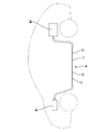
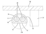
本実施例におけるワイヤハーネスWは、電気自動車あるいはハイブリッド車に搭載されるものである。このワイヤハーネスWは、複数(本実施例では2本)の電線20と、電線20を保護する電線保護パイプ(以後、単にパイプ10と称する)とを備えている。ワイヤハーネスWは、車両の前部に搭載された機器(モータ・インバータ等)M1と車両の後部に搭載された機器(高圧バッテリ等)M2とを接続する。ワイヤハーネスWは、車両前部から車両後部にわたるものであり、全長が3~4m程度とされている。ワイヤハーネスWの大部分は、図1に示すように、車両の床下(床板30の下方)に配索される。以下、各構成部材において、ワイヤハーネスWを車体に取り付けた状態における上側を上方、下側を下方として説明する。 Example 1
Hereinafter, an embodiment of the present invention will be described in detail with reference to FIGS. 1 to 6.
The wire harness W in the present embodiment is mounted on an electric car or a hybrid car. The wire harness W includes a plurality of (two in the present embodiment)electric wires 20 and a wire protection pipe (hereinafter simply referred to as a pipe 10) for protecting the electric wires 20. The wire harness W connects a device (motor, inverter, etc.) M1 mounted on the front of the vehicle and a device (high-voltage battery, etc.) M2 mounted on the rear of the vehicle. The wire harness W extends from the front of the vehicle to the rear of the vehicle and has a total length of about 3 to 4 m. Most of the wire harness W is routed under the floor of the vehicle (below the floor plate 30) as shown in FIG. Hereinafter, in each component, the upper side in the state which attached the wire harness W to the vehicle body is demonstrated as upper side, and the lower side is downward.
以下、本発明を具体化した一実施例について、図1~図6を参照しつつ詳細に説明する。
本実施例におけるワイヤハーネスWは、電気自動車あるいはハイブリッド車に搭載されるものである。このワイヤハーネスWは、複数(本実施例では2本)の電線20と、電線20を保護する電線保護パイプ(以後、単にパイプ10と称する)とを備えている。ワイヤハーネスWは、車両の前部に搭載された機器(モータ・インバータ等)M1と車両の後部に搭載された機器(高圧バッテリ等)M2とを接続する。ワイヤハーネスWは、車両前部から車両後部にわたるものであり、全長が3~4m程度とされている。ワイヤハーネスWの大部分は、図1に示すように、車両の床下(床板30の下方)に配索される。以下、各構成部材において、ワイヤハーネスWを車体に取り付けた状態における上側を上方、下側を下方として説明する。 Example 1
Hereinafter, an embodiment of the present invention will be described in detail with reference to FIGS. 1 to 6.
The wire harness W in the present embodiment is mounted on an electric car or a hybrid car. The wire harness W includes a plurality of (two in the present embodiment)
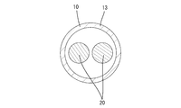
電線20は、可撓性を有する導体(例えば複数の金属素線を撚り合わせてなる撚線導体)を絶縁被覆で覆った、シールド機能を持たない通常の電線20である。電線の端部には図示しない端子金具が接続され、端子金具は、機器に接続可能なコネクタの内部に収容されている。
The electric wire 20 is a normal electric wire 20 having no shielding function, in which a flexible conductor (for example, a stranded conductor formed by twisting a plurality of metal strands) is covered with an insulating coating. A terminal fitting (not shown) is connected to the end of the wire, and the terminal fitting is accommodated inside a connector connectable to the device.
ワイヤハーネスWは、電線20のうちパイプ10から導出している部分を包囲してシールドするシールド部材(図示せず)を備えている。シールド部材は、金属細線を筒状に編み込んだ編組部材や金属テープ等であり、シールド性及び可撓性を有している。シールド部材の一端は、パイプ10の軸方向の両端部に導通可能に接続され、他端は、コネクタに接続されている。パイプ10及びシールド部材によって、電線20の全長が覆われることにより、電線20から発生する電磁ノイズが遮蔽されている。
The wire harness W includes a shield member (not shown) that surrounds and shields a portion of the electric wire 20 which is led out from the pipe 10. The shield member is a braided member, a metal tape or the like in which metal thin wires are woven in a tubular shape, and has shieldability and flexibility. One end of the shield member is conductively connected to both axial ends of the pipe 10, and the other end is connected to the connector. By covering the entire length of the wire 20 with the pipe 10 and the shield member, electromagnetic noise generated from the wire 20 is shielded.
パイプ10は、電線20のうち少なくとも床下に配される部分を包囲し、電線20に異物が干渉することを防ぐ。パイプ10は、金属製(例えば銅あるいは銅合金、またアルミニウムあるいはアルミニウム合金)の長尺な管体であり、シールド性及び形状保持性を有している。パイプ10は、ベンダー機によって所定の形状に曲げ加工(塑性変形)され、所定の曲げ形状を保持している。パイプ10の内部には、複数の電線20が一括して挿通されている。
The pipe 10 surrounds at least a portion of the electric wire 20 disposed under the floor, and prevents foreign matter from interfering with the electric wire 20. The pipe 10 is a long pipe made of metal (for example, copper or copper alloy, or aluminum or aluminum alloy), and has shielding properties and shape retention. The pipe 10 is bent (plastically deformed) into a predetermined shape by a bender machine, and holds a predetermined bending shape. A plurality of electric wires 20 are collectively inserted in the pipe 10.
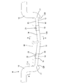
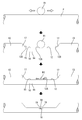
パイプ10は、図2に示すように、車体の床板30の下方に配される床下部11を備えている。床下部11は、パイプ10の軸方向における両端部を除く大部分に設けられている。パイプ10の両端部(床下部11より前側の部分及び後側の部分)は、車体に取り付けられた状態において上向きに屈曲されている。なお、本実施例では、床下部11は、車体に固定された状態において、軸方向の両端から中央部に向かって次第に下がるように傾斜している。
The pipe 10, as shown in FIG. 2, includes an underfloor 11 disposed below the floor plate 30 of the vehicle body. The underfloor 11 is provided in most parts except for both ends in the axial direction of the pipe 10. Both ends (a part on the front side and a part on the rear side of the floor lower part 11) of the pipe 10 are bent upward in a state of being attached to the vehicle body. In the present embodiment, the lower floor portion 11 is inclined so as to gradually lower from both axial ends toward the central portion in a state fixed to the vehicle body.
床下部11には、車体に取り付けられた状態における下側に凹み部12が形成されている。凹み部12は、真円形状をなす断面の片側のみを凹ませたものである。凹み部12は、床下部11の大部分(本実施例ではほぼ全体)にわたって設けられている。
The lower floor portion 11 is provided with a recess 12 on the lower side in a state of being attached to the vehicle body. The recess 12 is formed by recessing only one side of a cross section having a true circular shape. The recess 12 is provided over most of the floor floor 11 (in the present embodiment, substantially the whole).
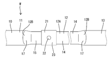
凹み部12は、床下部11の軸方向における所定範囲(この範囲は車体等の条件にあわせて適宜変更できる)にわたり連続した形態をなしている。凹み部12は、本実施例では、一続きのものが一のみ設けられている。凹み部12の上下方向の寸法(凹み寸法)は、全体において一定とされている。凹み部12を側方(パイプ10の軸線に対して交差する水平方向)から見ると、パイプ10の軸方向に延びる平らな面12Aと、その両端からパイプ10の径方向外方(本実施例では下方)に向かって立つ端面12Bとを有して、パイプ10の径方向の片側(下側)に開放された形状をなしている。凹み部12の平らな面12Aと端面12Bとの交差部分は丸く湾曲している。パイプ10のうち凹み部12が形成されない部分は、断面が真円(楕円または長円等を含まない円)形状をなす真円部13として残されている。
The recess 12 has a continuous form over a predetermined range in the axial direction of the floor lower portion 11 (this range can be appropriately changed according to the conditions of the vehicle body etc.). In the present embodiment, only one continuous concave portion 12 is provided. The vertical dimension (dent size) of the recess 12 is made constant throughout. When the recess 12 is viewed from the side (horizontal direction intersecting the axis of the pipe 10), the flat surface 12A extending in the axial direction of the pipe 10 and the radial outward of the pipe 10 from its both ends (this embodiment) Then, it has an end face 12B which faces downward (downward) and is open at one side (lower side) of the pipe 10 in the radial direction. The intersection of the flat surface 12A and the end surface 12B of the recess 12 is rounded and curved. The portion of the pipe 10 where the recessed portion 12 is not formed is left as a true circle portion 13 whose cross section has a true circle (circle without ellipse or oval or the like) shape.
床下部11のうち凹み部12が形成された部分は、図5に示すように、軸方向と交差する断面が扁平な形状をなす扁平部14となっている。扁平部14の幅寸法(図5における左右方向の寸法)は、真円部13の幅寸法と同等もしくは若干大きくされている。扁平部14の断面形状は、左右方向に長い形状をなしている。
As shown in FIG. 5, the portion of the floor lower portion 11 in which the recess 12 is formed is a flat portion 14 having a flat cross section intersecting with the axial direction. The width dimension (dimension in the left-right direction in FIG. 5) of the flat portion 14 is equal to or slightly larger than the width dimension of the perfect circle portion 13. The cross-sectional shape of the flat portion 14 is long in the left-right direction.
扁平部14は、凹み部12を構成する平らな平面部15と、平面部15の凹み部12とは反対側に設けられた円弧形状をなす曲面部16とを備えている。平面部15は、凹み部12の形成に伴って平らに潰された部分である。曲面部16は、凹み部12が形成される前の真円形状の一部が潰されずに残された部分である。
The flat portion 14 includes a flat surface portion 15 forming the recess 12 and an arc-shaped curved surface portion 16 provided on the opposite side to the recess 12 of the surface portion 15. The flat portion 15 is a portion crushed flat with the formation of the recess 12. The curved surface portion 16 is a portion where a part of the perfect circular shape before the recess 12 is formed is left without being crushed.
扁平部14の軸方向における両端部(以後、エッジ部17と称する)は、断面形状が、扁平部14側から真円部13側に向かって次第に真円に近づいている。また、エッジ部17の高さ寸法(上下方向の寸法)は、扁平部14側から真円部13側に向かって次第に増している。エッジ部17のうち凹み部12に臨む面(端面12B)は、パイプ10の軸方向に対して傾斜している。
Both end portions in the axial direction of the flat portion 14 (hereinafter referred to as edge portions 17) have a cross-sectional shape gradually approaching a perfect circle from the flat portion 14 side toward the true circular portion 13 side. Further, the height dimension (dimension in the vertical direction) of the edge portion 17 gradually increases from the flat portion 14 side toward the true circle portion 13 side. The surface (end surface 12B) of the edge portion 17 facing the recess 12 is inclined with respect to the axial direction of the pipe 10.
扁平部14の下面(平らな面12A)には、さらに一段凹んだ段差凹部18が設けられている。段差凹部18は、扁平部14の所定の位置(クランプ21の取り付け位置)に設けられている。段差凹部18は、複数箇所(本実施例では2箇)に設けられている。
The lower surface (flat surface 12A) of the flat portion 14 is provided with a stepped recess 18 further recessed by one step. The step recess 18 is provided at a predetermined position of the flat portion 14 (attachment position of the clamp 21). The step recesses 18 are provided at a plurality of locations (two in the present embodiment).
段差凹部18は、凹み部12より小さい凹部である。段差凹部18の深さ寸法(上下方向の寸法)及び長さ寸法(軸方向の寸法)は、凹み部12の深さ寸法及び長さ寸法に比していずれも小さくされている。段差凹部18の軸方向における両端には、平らな面12Aとの間に段差部19が形成されている。この段差部19が、クランプ21の軸方向における両端に当接することにより、クランプ21を位置決めする。
The step recess 18 is a recess smaller than the recess 12. The depth dimension (dimension in the vertical direction) and the length dimension (dimension in the axial direction) of the step recess 18 are smaller than the depth dimension and the length dimension of the recess 12. At both ends in the axial direction of the step recess 18, a step 19 is formed between the flat recess 12 and the flat surface 12A. The step portion 19 abuts on both ends in the axial direction of the clamp 21 to position the clamp 21.
段差凹部18にはクランプ21が取り付けられている。クランプ21は合成樹脂製であり、車体に固定される車体固定部22と、パイプ10に固定されるパイプ固定部23とを一体に備えている。
A clamp 21 is attached to the stepped recess 18. The clamp 21 is made of synthetic resin, and integrally includes a vehicle body fixing portion 22 fixed to the vehicle body and a pipe fixing portion 23 fixed to the pipe 10.
次に、本実施例におけるワイヤハーネスWを製造する方法の一例を説明する。
まず、全体が真円形状をなす従来のパイプ(以後、丸パイプPと称する)に電線20を挿通する。なお、図6では、電線20を省略している。 Next, an example of a method of manufacturing the wire harness W in the present embodiment will be described.
First, theelectric wire 20 is inserted into a conventional pipe (hereinafter referred to as a round pipe P) having a perfect circular shape as a whole. In addition, the electric wire 20 is abbreviate | omitted in FIG.
まず、全体が真円形状をなす従来のパイプ(以後、丸パイプPと称する)に電線20を挿通する。なお、図6では、電線20を省略している。 Next, an example of a method of manufacturing the wire harness W in the present embodiment will be described.
First, the
次いで、丸パイプPに凹み部12を形成する。凹み部12は、図6に示すように、加圧ローラR1により丸パイプPの片側を加圧して形成する。丸パイプPの片側にあてた加圧ローラR1を、丸パイプPの軸方向における所定範囲にわたり回転駆動し、徐々に加圧する。丸パイプPは、加圧ローラR1と、これに対向して配置された図示しない受け部材との間に挟みこまれ、加圧ローラR1の圧力によって徐々に潰され、扁平な形状になっていく。加圧ローラR1の駆動範囲には、平らな面12Aが形成されるとともに、その両端部には、加圧ローラR1の外周面に沿うように緩やかに湾曲して連続した端面12Bが形成される。このとき、加圧ローラR1をゆっくり加圧することにより、加工時の丸パイプPの座屈、特に真円部13との境となるエッジ部17における座屈などの破損を防ぐことができる。
こうして丸パイプPの所定範囲に凹み部12を形成することにより、所定範囲に扁平部14が形成されたパイプ10ができる。 Next, therecess 12 is formed in the round pipe P. The recess 12 is formed by pressing one side of the round pipe P by the pressure roller R1 as shown in FIG. The pressure roller R1 applied to one side of the round pipe P is rotationally driven over a predetermined range in the axial direction of the round pipe P, and is gradually pressurized. The round pipe P is sandwiched between the pressure roller R1 and a receiving member (not shown) disposed opposite to it, and is gradually crushed by the pressure of the pressure roller R1 and becomes flat. . In the driving range of the pressure roller R1, a flat surface 12A is formed, and at its both ends, an end surface 12B which is gently curved and continuous along the outer peripheral surface of the pressure roller R1 is formed . At this time, by pressing the pressure roller R1 slowly, it is possible to prevent breakage such as buckling of the round pipe P at the time of processing, in particular, buckling at the edge portion 17 which is a boundary with the perfect circle portion 13.
In this way, by forming therecess 12 in the predetermined range of the round pipe P, the pipe 10 in which the flat portion 14 is formed in the predetermined range can be obtained.
こうして丸パイプPの所定範囲に凹み部12を形成することにより、所定範囲に扁平部14が形成されたパイプ10ができる。 Next, the
In this way, by forming the
次に、段差凹部18を形成する。段差凹部18は、加圧ローラR1よりも一回り小さいローラ(以後、小型ローラR2と称する)により形成する。平面部15の所定の位置に小型ローラR2をあて、クランプ21を嵌め込む範囲にわたり小型ローラR2を軸方向に回転駆動させてゆっくり加圧し、段差凹部18を形成する。段差凹部18の軸方向における両端部には、凹み部12と同様、緩やかに湾曲して立つ段差部19が形成される。
Next, the step recess 18 is formed. The step concave portion 18 is formed by a roller (hereinafter, referred to as a small roller R2) which is slightly smaller than the pressure roller R1. The small roller R2 is brought into contact with a predetermined position of the flat portion 15, and the small roller R2 is rotationally driven in the axial direction over a range in which the clamp 21 is fitted to be slowly pressed to form the step recess. Similar to the recess 12, the step 19 is formed so as to be gently curved at both ends in the axial direction of the step recess 18.
次に、パイプ10を曲げ加工する。電線20の配策経路に沿うように、ベンダー機によって曲げ加工する。ここで、仮に扁平部14を曲げようとすると、曲げ部においてパイプ10が損傷等する虞がある。例えば扁平部14を上下方向(断面短手方向)に曲げる場合には、曲げ部において断面が潰れて内部の電線20を押圧する虞がある。また、扁平部14を左右方向(断面長手方向)に曲げる場合には、平面部15が座屈等してパイプ10が破損する虞がある。しかしながら、本実施例のパイプ10は、曲げ加工する部分を真円部13として残しているから、真円部13を曲げることでパイプ10を好適に曲げ加工することができる。
Next, the pipe 10 is bent. It bends with a bender machine so that the distribution route of the electric wire 20 may be followed. Here, if the flat portion 14 is to be bent, the pipe 10 may be damaged or the like at the bent portion. For example, when the flat portion 14 is bent in the vertical direction (crosswise direction), there is a possibility that the cross section may be crushed in the bent portion and the electric wire 20 in the inside may be pressed. In addition, when the flat portion 14 is bent in the left-right direction (longitudinal direction of the cross section), the flat portion 15 may be buckled and the pipe 10 may be damaged. However, in the pipe 10 of the present embodiment, since the portion to be bent is left as the perfect circle portion 13, it is possible to suitably bend the pipe 10 by bending the perfect circle portion 13.
次に、段差凹部18にクランプ21を取り付ける。段差凹部18に嵌め込むようにしてクランプ21を取り付けると、クランプ21の軸方向における両端部が、段差部19によって位置決めされる。
以上により、ワイヤハーネスWを製造する作業が完了する。 Next, theclamp 21 is attached to the step recess 18. When the clamp 21 is attached so as to be fitted in the step recess 18, both axial ends of the clamp 21 are positioned by the step 19.
Thus, the work of manufacturing the wire harness W is completed.
以上により、ワイヤハーネスWを製造する作業が完了する。 Next, the
Thus, the work of manufacturing the wire harness W is completed.
次に、上記のように構成された実施例の作用および効果について説明する。
本実施例のワイヤハーネスWは、内部に電線20が挿通されて車体に取り付けられるパイプ10を有し、パイプ10は、車体の床下に配される床下部11を備えている。床下部11には、車体に取り付けられた状態における下側に凹み部12が形成されることにより、軸方向と交差する断面が扁平な形状をなす扁平部14が設けられている。この構成によれば、扁平部14の高さ寸法は、真円形状をなすものに比して小さいため、地面等に接触しにくくすることができる。 Next, the operation and effects of the embodiment configured as described above will be described.
The wire harness W of the present embodiment has apipe 10 in which the electric wire 20 is inserted and attached to the vehicle body, and the pipe 10 includes a floor lower portion 11 disposed below the floor of the vehicle body. The floor lower portion 11 is provided with a flat portion 14 having a flat cross section intersecting with the axial direction by forming a recess 12 on the lower side in a state of being attached to a vehicle body. According to this configuration, since the height dimension of the flat portion 14 is smaller than that of the one having a perfect circular shape, it can be made difficult to contact the ground or the like.
本実施例のワイヤハーネスWは、内部に電線20が挿通されて車体に取り付けられるパイプ10を有し、パイプ10は、車体の床下に配される床下部11を備えている。床下部11には、車体に取り付けられた状態における下側に凹み部12が形成されることにより、軸方向と交差する断面が扁平な形状をなす扁平部14が設けられている。この構成によれば、扁平部14の高さ寸法は、真円形状をなすものに比して小さいため、地面等に接触しにくくすることができる。 Next, the operation and effects of the embodiment configured as described above will be described.
The wire harness W of the present embodiment has a
例えば図5に示すように、従来のような真円形状のパイプでは、床下の補強部材(クロスメンバ等)31の下端よりパイプの下端が地面等に近くなることがある。このような場合、車両衝突時にパイプが真っ先に地面や縁石等に接触しやすく、パイプが地面等に接触すると折れる等の破損をして、パイプ内の電線を保護することができない場合がある。しかしながら、本実施例では、凹み部12が形成されてパイプ10の高さ寸法が小さくなることにより、パイプ10の下端が補強部材31の下端より上方に位置できる。よって、パイプ10を地面等に接触しにくくすることができ、もってパイプ10内の電線を確実に保護することができる。
For example, as shown in FIG. 5, in the case of a conventional round pipe, the lower end of the pipe may be closer to the ground or the like than the lower end of a reinforcing member (cross member or the like) 31 under the floor. In such a case, the pipe may easily contact the ground or a curb at the beginning of a vehicle collision, and may break when the pipe contacts the ground or the like, resulting in failure to protect the electric wire in the pipe. However, in the present embodiment, the lower end of the pipe 10 can be positioned above the lower end of the reinforcing member 31 by forming the recess 12 and reducing the height dimension of the pipe 10. Thus, the pipe 10 can be made less likely to contact the ground or the like, and the electric wires in the pipe 10 can be reliably protected.
また、パイプ10は、扁平部14の凹み部12側に、さらに一段凹んだ段差凹部18が設けられている。この構成によれば、パイプ10を車体に取り付けるために用いるクランプ21を、段差凹部18に取り付けることにより、パイプ10の軸方向に位置決めすることができる。
Further, the pipe 10 is provided with a stepped recess 18 further recessed one step on the recessed portion 12 side of the flat portion 14. According to this configuration, the clamp 21 used to attach the pipe 10 to the vehicle body can be positioned in the axial direction of the pipe 10 by attaching to the stepped recess 18.
また、パイプ10は、断面が真円形状をなす真円部13を備え、真円部13が曲げ加工されている。ここで、扁平部14を曲げ加工しようとすると、潰れる等して断面形状を保持できない虞がある。しかしながら、この構成によれば、パイプ10の断面形状を適切に保持しつつワイヤハーネスWの配策経路に沿うように曲げ加工することができる。
Moreover, the pipe 10 is provided with the perfect circle part 13 which makes a section a perfect circle shape, and the perfect circle part 13 is bent. Here, when the flat portion 14 is to be bent, there is a possibility that the cross-sectional shape can not be maintained due to crushing or the like. However, according to this configuration, bending can be performed along the routing path of the wire harness W while appropriately holding the cross-sectional shape of the pipe 10.
また、ワイヤハーネスWが車体に取り付けられた状態では、扁平部14の下端が、車体を補強する補強部材31の下端より上方に位置する。この構成によれば、扁平部14の下端が補強部材31の下端よりも先に地面等にあたりにくいから、パイプ10をより確実に地面等に接触しにくくすることができる。
Further, in a state where the wire harness W is attached to the vehicle body, the lower end of the flat portion 14 is positioned above the lower end of the reinforcing member 31 that reinforces the vehicle body. According to this configuration, since it is difficult for the lower end of the flat portion 14 to hit the ground or the like earlier than the lower end of the reinforcing member 31, the pipe 10 can be more reliably prevented from contacting the ground or the like.
<実施例2>
次に、本発明を具体化した実施例2に係るワイヤハーネス40を図7及び図8によって説明する。
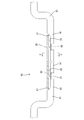
本実施例のワイヤハーネス40は、車体に取り付けられた状態における上側に凹み部12が形成されている点で、実施例1とは相違する。なお、実施例1と同様の構成には同一符号を付して重複する説明を省略する。 Example 2
Next, awire harness 40 according to a second embodiment of the present invention will be described with reference to FIGS. 7 and 8.
Thewire harness 40 of this embodiment is different from that of the first embodiment in that the recess 12 is formed on the upper side in a state of being attached to the vehicle body. The same components as those of the first embodiment are denoted by the same reference numerals and the description will not be repeated.
次に、本発明を具体化した実施例2に係るワイヤハーネス40を図7及び図8によって説明する。
本実施例のワイヤハーネス40は、車体に取り付けられた状態における上側に凹み部12が形成されている点で、実施例1とは相違する。なお、実施例1と同様の構成には同一符号を付して重複する説明を省略する。 Example 2
Next, a
The
本実施例に係るワイヤハーネス40は、実施例1と同様に、内部に電線20が挿通されて車体に取り付けられる電線保護パイプ(以後、単にパイプ41と称する)を有し、パイプ41は、車体の床下に配される床下部42を備え、床下部42には、凹み部12が形成されることにより、軸方向と交差する断面が扁平な形状をなす扁平部14が設けられている。また、パイプ41は、実施例1と同様に、断面が真円形状をなす真円部13を備え、真円部13が曲げ加工されている。扁平部14の平面部15には、実施例1と同様、さらに一段凹んだ段差凹部18が設けられ、段差凹部18にはクランプ21が固定されている。
As in the first embodiment, the wire harness 40 according to the present embodiment includes a wire protection pipe (hereinafter simply referred to as a pipe 41) into which the electric wire 20 is inserted and attached to the vehicle body. The floor lower portion 42 is disposed below the floor, and the floor lower portion 42 is provided with a flat portion 14 having a flat cross section intersecting with the axial direction by forming the recess 12. Further, as in the first embodiment, the pipe 41 is provided with a true circular portion 13 whose cross section has a true circular shape, and the true circular portion 13 is bent. Similar to the first embodiment, a step recess 18 further recessed by one step is provided in the flat portion 15 of the flat portion 14, and a clamp 21 is fixed to the step recess 18.
本実施例におけるワイヤハーネス40は、概ね実施例1と同様の方法で製造される。
本実施例におけるワイヤハーネス40を車体に取り付けた状態では、図7及び図8に示すように、パイプ41の扁平部14が床板30の下面に沿って配され、扁平部14の下端が、車体を補強するために用いられる補強部材(クロスメンバ等)31の下端より上方に位置している。 Thewire harness 40 in the present embodiment is manufactured in substantially the same manner as in the first embodiment.
In a state where thewire harness 40 in the present embodiment is attached to the vehicle body, as shown in FIGS. 7 and 8, the flat portion 14 of the pipe 41 is disposed along the lower surface of the floor plate 30, and the lower end of the flat portion 14 is the vehicle body. Are positioned above the lower end of a reinforcing member (cross member or the like) 31 used to reinforce the
本実施例におけるワイヤハーネス40を車体に取り付けた状態では、図7及び図8に示すように、パイプ41の扁平部14が床板30の下面に沿って配され、扁平部14の下端が、車体を補強するために用いられる補強部材(クロスメンバ等)31の下端より上方に位置している。 The
In a state where the
本実施例では、扁平部14の平面部15は上側に配され、扁平部14の曲面部16は下側に配されている。平面部15は、床板30と略平行をなし、床板30に近接して配することができる。一方、曲面部16は下側に配されるから、平面部15が下側に配される場合に比して、地面から離れるという点で有利である。すなわち平面部15は全体において地面との距離が一定であるのに対し、曲面部16は、湾曲している部分が、下端と地面との距離に比して地面から遠く離れるからである。
In the present embodiment, the flat portion 15 of the flat portion 14 is disposed on the upper side, and the curved portion 16 of the flat portion 14 is disposed on the lower side. The flat portion 15 is substantially parallel to the floor plate 30 and can be disposed close to the floor plate 30. On the other hand, since the curved surface portion 16 is disposed on the lower side, it is advantageous in that it is separated from the ground as compared with the case where the flat surface portion 15 is disposed on the lower side. That is, while the flat portion 15 has a constant distance to the ground as a whole, the curved portion 16 has a curved portion far from the ground as compared to the distance between the lower end and the ground.
以上のように本実施例のワイヤハーネス40は、内部に電線20が挿通されて車体に取り付けられるパイプ41を有し、パイプ41は、車体の床下に配される床下部42を備え、床下部42には、車体に取り付けられた状態における下側に凹み部12が形成されることにより、軸方向と交差する断面が扁平な形状をなす扁平部14が設けられているから、実施例1と同様、扁平部14の高さ寸法は、真円形状をなすものに比して小さいため、地面等に接触しにくくすることができる。
As described above, the wire harness 40 of the present embodiment has the pipe 41 into which the electric wire 20 is inserted and attached to the vehicle body, and the pipe 41 includes the underfloor 42 disposed under the floor of the vehicle body. The flat portion 14 having a flat cross section intersecting with the axial direction is provided at 42 by forming the recessed portion 12 on the lower side in a state of being attached to the vehicle body, and thus Similarly, since the height dimension of the flat portion 14 is smaller than that of a true circular shape, it can be made difficult to contact the ground or the like.
<他の実施例>
本発明は上記記述及び図面によって説明した実施例に限定されるものではなく、例えば次のような実施例も本発明の技術的範囲に含まれる。
(1)上記実施例では、パイプ10(41)は金属製とされているが、これに限らず、パイプは合成樹脂製であってもよく、また、樹脂パイプ内に金属箔を同心で埋め込んだ構造のもの等であってもよい。
(2)上記実施例では、段差凹部18を扁平部14に設けたが、段差凹部は必ずしも設けなくてもよく、また段差凹部は真円部に設けても良い。
(3)上記実施例では、パイプ10(41)に一続きの凹み部12が一のみ形成されているが、これに限らず、凹み部は、パイプに複数形成してもよい。
(4)上記実施例では、凹み部12及び段差凹部18を形成した後にパイプ10を曲げ加工しているが、これに限らず、凹み部及び段差凹部を形成するより先に曲げ加工を行ってもよい。 Other Embodiments
The present invention is not limited to the embodiments described above with reference to the drawings. For example, the following embodiments are also included in the technical scope of the present invention.
(1) In the above embodiment, the pipe 10 (41) is made of metal, but the pipe is not limited to this, and the pipe may be made of synthetic resin, and metal foil is concentrically embedded in the resin pipe It may be of a hollow structure.
(2) Although thestep recess 18 is provided in the flat portion 14 in the above embodiment, the step recess may not necessarily be provided, and the step recess may be provided in a true circle.
(3) In the above embodiment, only onecontinuous recess 12 is formed in the pipe 10 (41). However, the present invention is not limited to this. A plurality of recesses may be formed in the pipe.
(4) In the above embodiment, thepipe 10 is bent after the recess 12 and the step recess 18 are formed. However, the present invention is not limited to this. The bending is performed prior to forming the recess and the step recess. It is also good.
本発明は上記記述及び図面によって説明した実施例に限定されるものではなく、例えば次のような実施例も本発明の技術的範囲に含まれる。
(1)上記実施例では、パイプ10(41)は金属製とされているが、これに限らず、パイプは合成樹脂製であってもよく、また、樹脂パイプ内に金属箔を同心で埋め込んだ構造のもの等であってもよい。
(2)上記実施例では、段差凹部18を扁平部14に設けたが、段差凹部は必ずしも設けなくてもよく、また段差凹部は真円部に設けても良い。
(3)上記実施例では、パイプ10(41)に一続きの凹み部12が一のみ形成されているが、これに限らず、凹み部は、パイプに複数形成してもよい。
(4)上記実施例では、凹み部12及び段差凹部18を形成した後にパイプ10を曲げ加工しているが、これに限らず、凹み部及び段差凹部を形成するより先に曲げ加工を行ってもよい。 Other Embodiments
The present invention is not limited to the embodiments described above with reference to the drawings. For example, the following embodiments are also included in the technical scope of the present invention.
(1) In the above embodiment, the pipe 10 (41) is made of metal, but the pipe is not limited to this, and the pipe may be made of synthetic resin, and metal foil is concentrically embedded in the resin pipe It may be of a hollow structure.
(2) Although the
(3) In the above embodiment, only one
(4) In the above embodiment, the
W,40…ワイヤハーネス
10,41…電線保護パイプ
11,42…床下部
12…凹み部
13…真円部
14…扁平部
18…段差凹部
20…電線
31…補強部材 W, 40 ... wire harness 10, 41 ... wire protection pipe 11, 42 ... floor lower part 12 ... recessed part 13 ... true circle part 14 ... flat part 18 ... stepped recess 20 ... electric wire 31 ... reinforcing member
10,41…電線保護パイプ
11,42…床下部
12…凹み部
13…真円部
14…扁平部
18…段差凹部
20…電線
31…補強部材 W, 40 ...
Claims (5)
- 内部に電線が挿通されて車体に取り付けられる電線保護パイプであり、
前記車体の床下に配される床下部と、
前記床下部に設けられ、前記車体に取り付けられた状態における上側または下側に凹み部が形成されることにより、軸方向と交差する断面が扁平な形状をなす扁平部と、
を備えている電線保護パイプ。 It is a wire protection pipe that is inserted inside the wire and attached to the vehicle body,
An underfloor disposed below the floor of the vehicle body;
A flat portion provided on the lower floor and having a concave portion formed on the upper side or the lower side in a state of being attached to the vehicle body, whereby a cross section intersecting with the axial direction has a flat shape;
Electrical wire protection pipe. - 前記扁平部の前記凹み部側に、さらに一段凹んだ段差凹部が設けられている請求項1に記載の電線保護パイプ。 The electric wire protection pipe according to claim 1, wherein a step concave portion further recessed by one step is provided on the concave portion side of the flat portion.
- 前記断面が真円形状をなす真円部を備え、前記真円部が曲げ加工されている請求項1または請求項2に記載の電線保護パイプ。 The electric wire protection pipe according to claim 1 or 2, further comprising a true circle portion in which the cross section has a true circle shape, and the true circle portion being bent.
- 前記車体に取り付けられた状態では、前記扁平部の下端が、前記車体を補強する補強部材の下端より上方に位置する請求項1ないし請求項3のいずれか一項に記載の電線保護パイプ。 The wire protection pipe according to any one of claims 1 to 3, wherein a lower end of the flat portion is positioned above a lower end of a reinforcing member for reinforcing the vehicle body in a state of being attached to the vehicle body.
- 請求項1ないし請求項4のいずれか一項に記載の電線保護パイプと、
前記電線保護パイプの内部に挿通された複数の電線と、
を備えているワイヤハーネス。 The wire protection pipe according to any one of claims 1 to 4.
A plurality of wires inserted into the wire protection pipe;
Wire harness equipped with.
Priority Applications (2)
| Application Number | Priority Date | Filing Date | Title |
|---|---|---|---|
| US16/757,660 US10913406B2 (en) | 2017-10-30 | 2018-10-09 | Wire protection pipe and wire harness |
| CN201880067318.8A CN111226362B (en) | 2017-10-30 | 2018-10-09 | Electric wire protection tube and wire harness |
Applications Claiming Priority (2)
| Application Number | Priority Date | Filing Date | Title |
|---|---|---|---|
| JP2017-208718 | 2017-10-30 | ||
| JP2017208718A JP6848814B2 (en) | 2017-10-30 | 2017-10-30 | Wire protection pipe and wire harness |
Publications (1)
| Publication Number | Publication Date |
|---|---|
| WO2019087701A1 true WO2019087701A1 (en) | 2019-05-09 |
Family
ID=66332558
Family Applications (1)
| Application Number | Title | Priority Date | Filing Date |
|---|---|---|---|
| PCT/JP2018/037556 WO2019087701A1 (en) | 2017-10-30 | 2018-10-09 | Electric wire protection pipe, and wire harness |
Country Status (4)
| Country | Link |
|---|---|
| US (1) | US10913406B2 (en) |
| JP (1) | JP6848814B2 (en) |
| CN (1) | CN111226362B (en) |
| WO (1) | WO2019087701A1 (en) |
Cited By (1)
| Publication number | Priority date | Publication date | Assignee | Title |
|---|---|---|---|---|
| WO2020261932A1 (en) * | 2019-06-25 | 2020-12-30 | 住友電装株式会社 | Wire harness |
Families Citing this family (1)
| Publication number | Priority date | Publication date | Assignee | Title |
|---|---|---|---|---|
| JP7371550B2 (en) * | 2020-03-23 | 2023-10-31 | 株式会社オートネットワーク技術研究所 | wire harness |
Citations (2)
| Publication number | Priority date | Publication date | Assignee | Title |
|---|---|---|---|---|
| JP2013135500A (en) * | 2011-12-26 | 2013-07-08 | Auto Network Gijutsu Kenkyusho:Kk | Electric wire protection pipe and wire harness |
| JP2013243924A (en) * | 2013-07-02 | 2013-12-05 | Yazaki Corp | Wire harness |
Family Cites Families (11)
| Publication number | Priority date | Publication date | Assignee | Title |
|---|---|---|---|---|
| JPH10145938A (en) * | 1996-11-06 | 1998-05-29 | Nichidou Denko Kk | Mounting structure of wiring box |
| JP3909763B2 (en) | 2002-11-20 | 2007-04-25 | 株式会社オートネットワーク技術研究所 | Vehicle conductive path with shield function |
| JP5311921B2 (en) | 2008-08-19 | 2013-10-09 | 矢崎総業株式会社 | Wire harness |
| JP5269519B2 (en) * | 2008-08-19 | 2013-08-21 | 矢崎総業株式会社 | Wire harness manufacturing method |
| JP5576157B2 (en) * | 2010-03-16 | 2014-08-20 | 矢崎総業株式会社 | Wire harness and manufacturing method thereof |
| JP5722572B2 (en) * | 2010-08-24 | 2015-05-20 | 矢崎総業株式会社 | Wire harness |
| JP5803659B2 (en) * | 2011-12-26 | 2015-11-04 | 株式会社オートネットワーク技術研究所 | Wire protection pipe and wire harness |
| JP5874977B2 (en) * | 2012-09-18 | 2016-03-02 | 住友電装株式会社 | Grommet and mounting member with grommet |
| JP6149535B2 (en) * | 2013-06-20 | 2017-06-21 | 矢崎総業株式会社 | Wire harness |
| JP5713139B1 (en) * | 2014-11-12 | 2015-05-07 | 住友電装株式会社 | Wire protection pipe and wire harness |
| CN204359038U (en) * | 2014-11-26 | 2015-05-27 | 海信容声(广东)冰箱有限公司 | A kind of refrigerator sealing device and refrigerator |
-
2017
- 2017-10-30 JP JP2017208718A patent/JP6848814B2/en active Active
-
2018
- 2018-10-09 US US16/757,660 patent/US10913406B2/en active Active
- 2018-10-09 CN CN201880067318.8A patent/CN111226362B/en active Active
- 2018-10-09 WO PCT/JP2018/037556 patent/WO2019087701A1/en active Application Filing
Patent Citations (2)
| Publication number | Priority date | Publication date | Assignee | Title |
|---|---|---|---|---|
| JP2013135500A (en) * | 2011-12-26 | 2013-07-08 | Auto Network Gijutsu Kenkyusho:Kk | Electric wire protection pipe and wire harness |
| JP2013243924A (en) * | 2013-07-02 | 2013-12-05 | Yazaki Corp | Wire harness |
Cited By (1)
| Publication number | Priority date | Publication date | Assignee | Title |
|---|---|---|---|---|
| WO2020261932A1 (en) * | 2019-06-25 | 2020-12-30 | 住友電装株式会社 | Wire harness |
Also Published As
| Publication number | Publication date |
|---|---|
| US20200331413A1 (en) | 2020-10-22 |
| CN111226362A (en) | 2020-06-02 |
| US10913406B2 (en) | 2021-02-09 |
| JP6848814B2 (en) | 2021-03-24 |
| JP2019083603A (en) | 2019-05-30 |
| CN111226362B (en) | 2022-06-24 |
Similar Documents
| Publication | Publication Date | Title |
|---|---|---|
| US9112287B2 (en) | Swaging connection structure | |
| JP5231104B2 (en) | Wire harness | |
| US9991026B2 (en) | Conductive cable, method for producing the same, and wiring structure for the same | |
| EP2549601B1 (en) | Wire harness | |
| US8177591B2 (en) | Terminal fitting and electrical cable equipped with the same | |
| EP2549602B1 (en) | Wire harness and a method for producing same | |
| US9496071B2 (en) | Shield wire | |
| EP2317619B1 (en) | Protector and wire harness | |
| JP5269519B2 (en) | Wire harness manufacturing method | |
| US9396840B2 (en) | Shield conducting path | |
| CN103457064A (en) | Connector | |
| WO2019087701A1 (en) | Electric wire protection pipe, and wire harness | |
| WO2015198811A1 (en) | Shielded conduction path | |
| JP6434221B2 (en) | Wire harness | |
| US20150263496A1 (en) | Shield conductive path | |
| JP4823561B2 (en) | Shield conductive path | |
| US20190393686A1 (en) | Wire harness | |
| WO2016158400A1 (en) | Electric cable module and electric cable module manufacturing method | |
| CN110707443B (en) | Electric wire with terminal | |
| JP5629800B2 (en) | Wire harness | |
| JP5629799B2 (en) | Body underfloor wire harness protective member | |
| CN112435789A (en) | Pipe and wire harness | |
| WO2022203015A1 (en) | Connector unit | |
| JP6292452B2 (en) | Shield conductive path | |
| JP6278144B2 (en) | Electric wire and shield conductive path |
Legal Events
| Date | Code | Title | Description |
|---|---|---|---|
| 121 | Ep: the epo has been informed by wipo that ep was designated in this application |
Ref document number: 18872311 Country of ref document: EP Kind code of ref document: A1 |
|
| NENP | Non-entry into the national phase |
Ref country code: DE |
|
| 122 | Ep: pct application non-entry in european phase |
Ref document number: 18872311 Country of ref document: EP Kind code of ref document: A1 |