WO2019082318A1 - 動画像処理装置、動画像処理システム、及び動画像処理方法 - Google Patents
動画像処理装置、動画像処理システム、及び動画像処理方法Info
- Publication number
- WO2019082318A1 WO2019082318A1 PCT/JP2017/038582 JP2017038582W WO2019082318A1 WO 2019082318 A1 WO2019082318 A1 WO 2019082318A1 JP 2017038582 W JP2017038582 W JP 2017038582W WO 2019082318 A1 WO2019082318 A1 WO 2019082318A1
- Authority
- WO
- WIPO (PCT)
- Prior art keywords
- moving image
- unit
- data
- processing apparatus
- image processing
- Prior art date
Links
Images


Classifications
-
- H—ELECTRICITY
- H04—ELECTRIC COMMUNICATION TECHNIQUE
- H04N—PICTORIAL COMMUNICATION, e.g. TELEVISION
- H04N19/00—Methods or arrangements for coding, decoding, compressing or decompressing digital video signals
- H04N19/40—Methods or arrangements for coding, decoding, compressing or decompressing digital video signals using video transcoding, i.e. partial or full decoding of a coded input stream followed by re-encoding of the decoded output stream
-
- H—ELECTRICITY
- H04—ELECTRIC COMMUNICATION TECHNIQUE
- H04N—PICTORIAL COMMUNICATION, e.g. TELEVISION
- H04N21/00—Selective content distribution, e.g. interactive television or video on demand [VOD]
- H04N21/40—Client devices specifically adapted for the reception of or interaction with content, e.g. set-top-box [STB]; Operations thereof
- H04N21/43—Processing of content or additional data, e.g. demultiplexing additional data from a digital video stream; Elementary client operations, e.g. monitoring of home network or synchronising decoder's clock; Client middleware
- H04N21/44—Processing of video elementary streams, e.g. splicing a video clip retrieved from local storage with an incoming video stream, rendering scenes according to MPEG-4 scene graphs
- H04N21/44008—Processing of video elementary streams, e.g. splicing a video clip retrieved from local storage with an incoming video stream, rendering scenes according to MPEG-4 scene graphs involving operations for analysing video streams, e.g. detecting features or characteristics in the video stream
-
- G—PHYSICS
- G06—COMPUTING; CALCULATING OR COUNTING
- G06T—IMAGE DATA PROCESSING OR GENERATION, IN GENERAL
- G06T7/00—Image analysis
-
- H—ELECTRICITY
- H04—ELECTRIC COMMUNICATION TECHNIQUE
- H04N—PICTORIAL COMMUNICATION, e.g. TELEVISION
- H04N19/00—Methods or arrangements for coding, decoding, compressing or decompressing digital video signals
- H04N19/46—Embedding additional information in the video signal during the compression process
-
- H—ELECTRICITY
- H04—ELECTRIC COMMUNICATION TECHNIQUE
- H04N—PICTORIAL COMMUNICATION, e.g. TELEVISION
- H04N21/00—Selective content distribution, e.g. interactive television or video on demand [VOD]
- H04N21/20—Servers specifically adapted for the distribution of content, e.g. VOD servers; Operations thereof
- H04N21/23—Processing of content or additional data; Elementary server operations; Server middleware
- H04N21/235—Processing of additional data, e.g. scrambling of additional data or processing content descriptors
-
- H—ELECTRICITY
- H04—ELECTRIC COMMUNICATION TECHNIQUE
- H04N—PICTORIAL COMMUNICATION, e.g. TELEVISION
- H04N21/00—Selective content distribution, e.g. interactive television or video on demand [VOD]
- H04N21/40—Client devices specifically adapted for the reception of or interaction with content, e.g. set-top-box [STB]; Operations thereof
- H04N21/43—Processing of content or additional data, e.g. demultiplexing additional data from a digital video stream; Elementary client operations, e.g. monitoring of home network or synchronising decoder's clock; Client middleware
- H04N21/435—Processing of additional data, e.g. decrypting of additional data, reconstructing software from modules extracted from the transport stream
Definitions
- the present invention relates to a moving image processing apparatus, a moving image processing system, and a moving image processing method.
- an encoding unit that encodes a moving image
- an acquisition unit that acquires data used for processing in which the moving image is compressed and encoded by the encoding unit, and acquired by the acquisition unit
- a detection unit for detecting, from the moving image, feature data indicating features of the moving image based on the extracted data; data obtained by encoding the moving image by the encoding unit; and the data detected by the detection unit
- an output unit for outputting feature data.
- the process of detecting data relating to a predetermined detection target from a moving image can be performed relatively quickly.
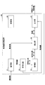
- FIG. 1 is a diagram showing a configuration example of a communication system 1 ("moving image processing system") according to the embodiment.
- the communication system 1 includes terminals 10-1, 10-2,... (Hereinafter simply referred to as “terminal 10” when it is not necessary to distinguish between each other), a moving image processing apparatus 20. , And the server 30.
- the number of terminals 10 is not limited to two.
- the terminal 10 and the moving image processing apparatus 20, and the moving image processing apparatus 20 and the server 30 are respectively connected by, for example, the network 40 such as the Internet, a mobile telephone network, a wireless LAN (Local Area Network), or LAN, and the network 50. It is connected in a communicable state.
- the network 40 such as the Internet, a mobile telephone network, a wireless LAN (Local Area Network), or LAN, and the network 50. It is connected in a communicable state.
- the terminal 10 is, for example, an information processing apparatus (computer) such as a surveillance camera, a video camera, a smartphone, or a moving image (video) file server.
- the terminal 10 encodes the moving image captured by the camera and the sound collected by the microphone according to a predetermined method ("first method"). Then, the terminal 10 distributes the encoded moving image and sound to the moving image processing apparatus 20 in real time by streaming distribution or the like. Alternatively, the terminal 10 stores the encoded moving image and sound as a file, and uploads the file to the moving image processing apparatus 20 at a predetermined timing.
- the moving image processing apparatus 20 is, for example, a transcoder that decodes a moving image captured and encoded by the terminal 10 and encodes the moving image according to a predetermined method ("second method").
- the moving image processing apparatus 20 decodes and encodes moving images and sounds received from the terminal 10, and distributes the encoded moving images and sounds to the server 30 in real time by streaming distribution or the like.
- the moving image processing apparatus 20 stores the encoded moving image and sound as a file, and uploads the file to the server 30 at a predetermined timing.
- moving images encoded by various encoding methods received from the terminal 10 can be converted into a predetermined encoding method and stored in the server 30.
- the moving image processing apparatus 20 detects feature data indicating the feature of the moving image, adds the detected feature data to the moving image, and uploads it to the server 30.
- the feature data may include data obtained by image processing or inference processing such as the position of the object, the moving direction of the object, and the moving speed, brightness, color, change in sound, volume, and the like.
- the server 30 monitors a suspicious person, manages a visitor, marketing a store, etc., distributes moving images, moving images, etc. by using AI (Artificial Intelligence) etc. using moving images and feature data received from the moving image processing apparatus 20, for example. Provide services such as image analysis.
- the server 30 may distribute moving images and sounds received from the moving image processing apparatus 20 to the information processing terminal of the user in real time.
- FIG. 2 is a diagram showing an example of the hardware configuration of the moving image processing apparatus 20 according to the embodiment.
- the moving image processing apparatus 20 shown in FIG. 2 includes a drive unit 200, an auxiliary storage unit 202, a memory unit 203, a CPU (Central Processing Unit) 204, an interface unit 205, a decoding circuit 206, and reference numerals mutually connected by a bus B. And a memory 208 and the like.
- a moving image processing program for realizing the processing in the moving image processing apparatus 20 is provided by the recording medium 201.
- the recording medium 201 in which the moving image processing program is recorded is set in the drive device 200
- the moving image processing program is installed from the recording medium 201 to the auxiliary storage device 202 via the drive device 200.
- the installation of the moving image processing program does not necessarily have to be performed from the recording medium 201, and may be downloaded from another computer via a network.
- the auxiliary storage device 202 stores the installed moving image processing program, and also stores necessary files and data.
- the memory device 203 reads out the program from the auxiliary storage device 202 and stores it when there is an instruction to start the program.
- the CPU 204 implements the function related to the moving image processing apparatus 20 in accordance with the program stored in the memory device 203.
- the interface device 205 is used as an interface for connecting to a network.
- Each of the decoding circuit 206 and the encoding circuit 207 is a circuit based on, for example, an LSI (Large Scale Integration) or the like, and is a circuit dedicated to decoding and encoding a moving image.
- the coding circuit 207 completes generation of predetermined data to be used for coding, and then generates a memory from the internal memory of the coding circuit 207 by a method such as DMA (Direct Memory Access).
- the data is transferred to the memory 208 and stored.
- the CPU 204 generates feature data to be described later using the data stored in the memory 208.
- the recording medium 201 a portable recording medium such as a CD-ROM, a DVD disc, or a USB memory may be mentioned.
- a hard disk drive (HDD) or a flash memory may be mentioned.
- the memory 208 may use part of the memory device 203.
- FIG. 3 is a diagram illustrating an example of a hardware configuration of the terminal 10 and the server 30 according to the embodiment.
- the server 30 will be described as an example.
- the server 30 of FIG. 3 includes a drive device 100, an auxiliary storage device 102, a memory device 103, a CPU 104, an interface device 105, and the like mutually connected by a bus B.
- a moving image processing program for realizing the processing in the server 30 is provided by the recording medium 101.
- the recording medium 101 in which the moving image processing program is recorded is set in the drive device 100, the moving image processing program is installed from the recording medium 101 to the auxiliary storage device 102 via the drive device 100.
- the installation of the moving image processing program does not necessarily have to be performed from the recording medium 101, and may be downloaded from another computer via a network.
- the auxiliary storage device 102 stores the installed moving image processing program and also stores necessary files and data.
- the memory device 103 reads out the program from the auxiliary storage device 102 and stores it when there is an instruction to start the program.
- the CPU 104 implements the function related to the server 30 in accordance with the program stored in the memory device 103.
- the interface device 105 is used as an interface for connecting to a network.
- the recording medium 101 a portable recording medium such as a CD-ROM, a DVD disk, or a USB memory may be mentioned.
- a hard disk drive (HDD) or a flash memory may be mentioned.
- the recording medium 101 and the auxiliary storage device 102 both correspond to computer readable recording media.
- the hardware configuration of the terminal 10 may be similar to that of the server 30.
- the terminal 10 includes a camera (imaging device) that captures a moving image.
- FIG. 4 is a diagram showing an example of the moving image processing apparatus 20 according to the embodiment.
- the moving image processing apparatus 20 includes a decoding unit 21, an encoding unit 22, an acquisition unit 23, a detection unit 24, an output unit 25, and a control unit 26.
- the decoding unit 21 is realized by the processing that the CPU 204 of the moving image processing apparatus 20 executes one or more programs installed in the moving image processing apparatus 20 or the decoding circuit 206 shown in FIG. 2.
- the decoding circuit 206 shown in FIG. 2 may not be provided.
- the CPU 204 may be a multi-core processor, and the decoding process by the decoding unit 21 and the process of detecting feature data (metadata) by the detection unit 24 may be processed in parallel using different cores.
- the decoding unit 21 may not be included.
- the encoding unit 22 is realized using the encoding circuit 207 shown in FIG.
- the acquisition unit 23 is realized using the memory 208 illustrated in FIG.
- the detection unit 24, the output unit 25, and the control unit 26 are realized by processing that one or more programs installed in the moving image processing apparatus 20 cause the CPU 204 of the moving image processing apparatus 20 to execute.
- a circuit for realizing the detection unit 24, the output unit 25, and the control unit 26 may be provided.
- the decoding unit 21 decodes the moving image received from the terminal 10.
- the encoding unit 22 is a unit of High Efficiency Video Coding (HEVC) / H. H. 265 (hereinafter referred to as "HEVC"), or AVC (Advanced Video Coding) / H.
- HEVC High Efficiency Video Coding
- AVC Advanced Video Coding
- the moving image decoded by the decoding unit 21 is compressed and encoded using a moving image compression standard such as H.264.
- the acquisition unit 23 acquires data used for processing in which a moving image is compressed and encoded by the encoding unit 22.
- the detection unit 24 detects feature data indicating features of the moving image received from the terminal 10 from the moving image based on the data acquired by the acquisition unit 23.
- the output unit 25 transmits, to the server 30, the data in which the moving image is encoded by the encoding unit 22 and the feature data detected by the detection unit 24.
- the transmission of the encoded data of the moving image and the feature data from the output unit 25 to the server 30 may be transmitted for each frame of the moving image, or a plurality of frames may be collectively transmitted.
- the control unit 26 controls the entire moving image processing apparatus 20.
- FIG. 5 is a diagram showing an example of a functional block diagram of the server 30 according to the embodiment.
- the server 30 includes a decoding unit 31, a data processing unit 32, and a display control unit 33.
- the decryption unit 31, the data processing unit 32, and the display control unit 33 are realized by processing that one or more programs installed in the server 30 are executed by the CPU 104 of the server 30.
- the decoding unit 31 decodes the moving image and the sound received from the moving image processing apparatus 20.
- the data processing unit 32 performs predetermined data processing using the feature data received from the moving image processing apparatus 20 and the moving image decoded by the decoding unit 31.
- the data processing unit 32 performs, for example, higher-load image processing, audio processing, and inference processing as predetermined data processing.
- the display control unit 33 superimposes or adds feature data or the result of data processing to the decoded moving image and displays the result.
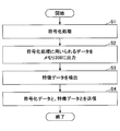
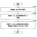
- FIG. 6 is a flowchart showing an example of processing for detecting feature data of the moving image processing apparatus 20. The following processing is performed on each frame in the moving image.
- step S1 the encoding unit 22 compresses and encodes a moving image.
- the encoding unit 22 outputs data used for the encoding process to the memory 208 (step S2).
- data used for the encoding process is stored in the memory 208 from the encoding circuit 207 shown in FIG.
- the CPU 204 can refer to the data used for the encoding process stored in the memory 208.
- step S1 by the encoding unit 22 and the detection process by the detection unit 24 are executed in parallel. Since the encoding process by the encoding circuit 207 is a process by dedicated hardware, for example, when a real-time moving image is received from the terminal 10 by streaming, it takes about 1/10 of the time required for real-time reception. Processing for the frame can be completed.
- the detection unit 24 detects feature data indicating features of the moving image received from the terminal 10 from the moving image, using the data stored in the memory 208 (step S3). As described above, by using the data used for the encoding process, the load of the process of detecting the feature data can be largely reduced.
- step S2 is performed in the middle of the encoding process. If the detection processing by the detection unit 24 has a processing load that can be completed within the time required for real-time reception of moving images, feature data can be detected in real time without the processing performance of the encoding circuit 207 being impaired. it can.
- the output unit 25 transmits the data in which the moving image is encoded by the encoding unit 22 and the feature data detected by the detection unit 24 to the server 30 (step S4).
- the output unit 25 includes, in the feature data, information when extracting feature data such as preconditions such as date and time, processing conditions and algorithms, and information such as the total number of scenes. Also, information extracted in units of each scene, each GOP (Group of Picture), and each frame is included.
- a scene is a unit having a frame as a key and a plurality of continuous frames (GOP), and the moving image processing apparatus 20 and the server 30 start moving image analysis processing.
- the information of each scene includes information such as the number of GOPs, the number of key frames, and the start position of the key frame.
- the information in each GOP unit includes information indicating the data configuration such as the number of frames, information extracted by the encoding process by the encoding unit 22, information detected by the detection unit 24, and the like.
- the information of each frame includes the information extracted from each frame by the encoding process by the encoding unit 22, the information detected from each frame by the detection unit 24, and the like.
- the total number of scenes includes information detected by the detection unit 24 based on all the scenes.
- the output unit 25 may transmit the feature data by a communication protocol different from that of the streaming of the encoded moving image, or may transmit the characteristic data by the same communication protocol.
- only feature data may be transmitted. Thereby, the amount of data to be transmitted can be reduced.
- the detection unit 24 may use the data stored in the memory 208 to detect feature data indicating features of each moving image received from the plurality of terminals 10 from each moving image.
- moving images from a plurality of terminals 10 may be integrated to detect feature data.
- the detection unit 24 sets the time of the moving image from each terminal 10 based on the moving image of the portion where the imaging ranges of each terminal 10 overlap, which is set in advance. May be transmitted from the output unit 25 respectively.
- Example 1 of feature data detection processing As an example 1 of feature data detection processing, CTU (Coding Tree Unit) (an example of “a block that is a unit in which the encoding processing is performed by the encoding unit 22”) obtained during encoding processing such as HEVC is used. An example will be described in which relatively non-background structures or background feature data are detected relatively quickly.
- CTU Coding Tree Unit
- the encoding unit 22 performs encoding processing of each frame (picture) in a moving image in units of square pixel blocks called CTUs using HEVC or the like.
- CTUs square pixel blocks
- the size of each block in the frame is determined according to the presence of the contour in the frame image and the complexity of the contour.
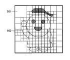
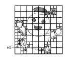
- FIG. 7 is a diagram for explaining an example of a CTU. As shown in FIG. 7, the flat background portion is divided by a relatively large block (CB: Coding Block) 501. Also, the outline of the object is divided by a relatively small block 502.
- CB Coding Block
- the encoding unit 22 stores CTU data in the memory 208.
- the CTU data stored in the memory 208 includes data such as the hierarchical structure and CB size of each CTB (Coding Tree Block) which is a block of each color component signal to be configured, and adjacent CTB.
- CTB Coding Tree Block
- the detection unit 24 may use CTU data stored in the memory 208 as feature data. This makes it possible, for example, to distinguish between a background such as sky or wall and an object having a structure such as a person or a building using feature data that is CTU data, and that the composition is similar from stored data. Data can be extracted.
- the detection unit 24 may detect, for example, an area to be detected in an image using data of the CTU, and may use data of the detected area as feature data. In this case, when, for example, a person or the like is to be detected, the detection unit 24 may execute a process of detecting a face by preferentially searching an area whose size of the CB is equal to or less than a predetermined value.
- a known algorithm may be used as an algorithm for detecting a person or the like.
- CTU data as a search range only for the area in which the size of CB is less than a predetermined value (for example, 16 ⁇ 16). This makes it possible to detect at a higher speed as compared to the conventional search range of the entire image.
- the detection unit 24 executes processing for detecting the background with a region having a size of CB equal to or larger than a predetermined value (for example, 32 ⁇ 32). You may
- Example 2 of feature data detection process As an example 2 of the feature data detection process, an example in which feature data related to the movement of an object is detected at relatively high speed using a reduced image obtained during the encoding process will be described.
- a reduced image (predicted image) of each frame is generated for motion compensation.
- the encoding unit 22 stores data of the generated reduced image in the memory 208.
- the detection unit 24 may use data of the reduced image stored in the memory 208 as feature data.
- the server 30 can use the feature data for, for example, motion search.
- the detection unit 24 may detect, for example, the movement of the detection target in the image using the data of the reduced image, and may use the detected movement data as feature data.
- the detection unit 24 finds a plurality of search starting point regions, selects a search starting point region having a high degree of similarity from among the plurality of candidates, and sets the selected starting starting region as feature data.
- the server 30 can finely search the search starting point included in the feature data and the periphery thereof using the same size image.
- Example 3 of feature data detection processing An example in which feature data relating to motion of an object is detected relatively quickly using data indicating changes between a plurality of consecutive frames obtained during encoding processing will be described. .
- data indicating changes between a plurality of consecutive frames is generated for motion compensation and the like.
- the data indicating the change between each frame includes, for example, a difference, a motion vector, and the like.
- the difference is the sum of absolute differences between the luminance and chrominance values of each pixel in a predetermined range included in the current frame, and the luminance and chrominance values of each pixel in the predetermined range included in the previous frame (SAD Sum of Absolute Difference, Sum of Squared Difference (SSD), Sum of Absolute Transformed Difference (SATD), and the like.
- the motion vector is data indicating the moving direction of the current block to be coded predicted between successive frames.
- motion compensation prediction is performed for every prediction block (PU: Prediction Unit).
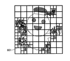
- FIG. 8A and 8B are diagrams for describing motion information in HEVC. Since each adjacent prediction block is considered to have similar motion, in HEVC, instead of encoding a separate motion vector for each prediction block, the motion vectors of each adjacent prediction block are integrated. And encode.
- the motion vector for each prediction block is indicated by an arrow 801 or the like.
- the motion vector integrated in each adjacent prediction block is indicated by an arrow 802 or the like.
- the encoding unit 22 When the encoding unit 22 generates the data for motion compensation, the encoding unit 22 stores the generated data in the memory 208.
- the detection unit 24 may set each data stored in the memory 208 as feature data.
- the server 30 can use the feature data for, for example, motion search.
- the detection unit 24 may detect, for example, the movement or the like of the detection target in the image using the respective data, and may use data of the detected movement as feature data.
- the detection unit 24 is a set of a predetermined number or more of prediction blocks, and the motion of the set of prediction blocks in which the size of each prediction block is a predetermined value or less is integrated by the encoding unit 22.
- the area of each prediction block included in the set may be preferentially searched. Thereby, for example, when analyzing a moving image in real time, the accuracy of the process of detecting a moving object can be further improved, and the process can be further speeded up.
- Example 4 of feature data detection process As an example 4 of feature data detection processing, an example will be described in which feature data relating to complexity is detected at relatively high speed using data indicating the complexity of a frame obtained during encoding processing.
- each data such as luminance in one frame, SAD (sum of absolute difference) of color difference, and SATD (sum of absolute value conversion difference) is calculated.
- the encoding unit 22 When the encoding unit 22 generates the respective data in intra prediction, the encoding unit 22 stores the generated data in the memory 208.
- the detection unit 24 may set each data stored in the memory 208 as feature data.
- the feature data detection process described above for example, in a surveillance camera system that monitors moving images and sounds from a surveillance camera, the position and size of a face in an image, recognition of a photographed person, age and gender of a person It is possible to detect feature data regarding the color of clothes of people, belongings such as glasses, hats and bags, etc.
- the camera installation position and orientation, lens angle of view, distortion, characteristics, etc. are known, or if camera calibration is performed in advance using a predetermined marker or the like, the size of the person photographed The feature data regarding the distance from the sheath and the camera can be detected.
- the feature data includes, for example, information such as the face and body, the direction of the foot, the movement of the hand and foot, the position of each joint, (face expression), and the action and motion estimated including these Information may be included.
- the information may be detected every several frames or several seconds.
- actions in a relatively wide range may be detected from moving images captured respectively by a plurality of cameras, and the detected action range may be used as feature data. In this way, it is possible to display the trajectory of the person or the object on the terminal of the user.
- FIG. 9 is a flowchart showing an example of display processing based on feature data in the server 30.
- 10A and 10B are diagrams for explaining an example of display processing based on feature data in the server 30.
- FIG. 9 is a flowchart showing an example of display processing based on feature data in the server 30.
- 10A and 10B are diagrams for explaining an example of display processing based on feature data in the server 30.
- step S101 the decoding unit 31 decodes the moving image and sound received from the moving image processing apparatus 20.
- the data processing unit 32 performs predetermined data processing using the feature data received from the moving image processing apparatus 20 and the moving image decoded by the decoding unit 31 (step S102).
- the process of step S101 and the process of step S102 may be performed simultaneously by parallel processing.
- the display control unit 33 superimposes or adds feature data or the result of data processing to the decoded moving image and displays the result (step S103).
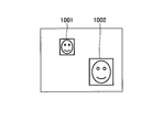
- the areas of the faces of the two persons included in the feature data received from the moving image processing apparatus 20 are displayed superimposed on the moving image by a frame 1001 and a frame 1002.
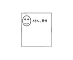
- the screen in FIG. 10B is displayed by an operation of pressing the inside of the frame 1002 or the like.
- the image in the frame 1002 and the information such as the name of the person in the frame 1002 and the gender are added and displayed.
- the moving image processing apparatus 20 or the data processing unit 32 collates the image in the frame 1002 with the face image registered in advance, and the similarity is a predetermined value.
- the name, gender, etc. associated with the highest person may be displayed.
- the moving image processing program detects feature data by processing of the CPU 204 using data generated for encoding by the encoding circuit 207 which is dedicated hardware.
- the moving image is encoded by the encoding circuit 207 which is a dedicated circuit, or
- the moving image processing program switches whether encoding is performed by the processing of the CPU 204 or the like.
- the encoding circuit 207 is a circuit specialized for a high definition moving image having a relatively high frame resolution, and the CPU 204 is processed rather than processing the low resolution moving image by the encoding circuit 207. It is assumed that it is faster to use the program and process it.
- the type of feature data to be detected needs to use data that is not generated by the implementation of the encoding circuit 207, and in the case of encoding by a program using the CPU 204, the data is generated. Do. Even in these cases, according to the second embodiment, in order to perform processing for detecting data relating to a predetermined detection target from a moving image using data generated for encoding, the processing is used. It can be done relatively fast.
- the second embodiment is the same as the first embodiment except for a part of the second embodiment, so the description will be appropriately omitted.
- description of parts in common with the first embodiment will be omitted, and only different parts will be described.
- the contents described in the second embodiment are also applicable to the first embodiment.
- FIG. 11 is a flowchart showing an example of processing of the moving image processing apparatus 20 according to the second embodiment.
- step S21 the control unit 26 determines whether the data size (frame resolution) of the moving image received from the terminal 10 is equal to or less than a first threshold.
- step S21 If it is equal to or less than the first threshold (YES in step S21), the decoding unit 21 decodes the moving image received from the terminal 10 by the processing of the moving image processing program using the CPU 204 (step S22). The process proceeds to step S24.
- the decoding unit 21 decodes the moving image received from the terminal 10 by the process of the decoding circuit 206 (step S23).
- control unit 26 determines whether the data size of the moving image received from the terminal 10 is equal to or less than the second threshold (step S24).
- the encoding unit 22 encodes the moving image received from the terminal 10 and decoded by the decoding unit 21 by the processing of the moving image processing program using the CPU 204 (Step S25), and the process ends.
- the encoding unit 22 encodes the moving image received from the terminal 10 and decoded by the decoding unit 21 by the process of the encoding circuit 207 (step S26) , End the process.
- the moving image processing apparatus 20 which is a transcoder, performs detection processing from a moving image by software processing, so that detection logic and the like can be changed.
- the above-described embodiment is a monitoring camera system that recognizes a person from an image, a digital marketing system that analyzes whether a customer grabs a product at a store, or purchases the product, etc., an IP distribution system, moving images of subject information
- the present invention can also be applied to an AR / VR system or the like that displays an image superimposed.
- Each functional unit of the moving image processing apparatus 20 may be realized by, for example, cloud computing configured by one or more computers. Also, the moving image processing apparatus 20 and the server 30 may be configured as an integrated apparatus. The moving image processing apparatus 20 and the terminal 10 may be configured as an integrated apparatus. In this case, the moving image processing apparatus 20 may not perform the moving image decoding process. The moving image processing apparatus 20 may have at least a part of the functional units of the terminal 10 or the server 30.
- the server 30 is an example of the “information processing apparatus”.
Abstract
動画像処理装置は、動画像を符号化する符号化部と、前記符号化部による前記動画像が圧縮されて符号化される処理に用いられるデータを取得する取得部と、前記取得部により取得されたデータに基づいて、前記動画像の特徴を示す特徴データを前記動画像から検出する検出部と、前記符号化部により前記動画像が符号化されたデータと、前記検出部により検出された前記特徴データとを出力する出力部と、を有する。
Description
本発明は、動画像処理装置、動画像処理システム、及び動画像処理方法に関する。
従来、監視カメラ、テレビ放送用のカメラ、スマートフォン等のカメラ等で撮影した動画像(映像)から、人物等を検出する技術が知られている(例えば、特許文献1-5を参照)。この検出処理は、ソフトウェア、または専用のハードウェアを用いて実行される。
また、カメラで撮影された動画像から、人の顔や行動等を検出する技術が知られている。
しかしながら、従来技術では、所定の検出対象に関するデータを動画像から検出する処理を行う場合、処理に比較的時間がかかるという問題がある。
そこで、一側面では、所定の検出対象に関するデータを動画像から検出する処理を、比較的高速に行うことができる技術を提供することを目的とする。
一つの案では、動画像を符号化する符号化部と、前記符号化部による前記動画像が圧縮されて符号化される処理に用いられるデータを取得する取得部と、前記取得部により取得されたデータに基づいて、前記動画像の特徴を示す特徴データを前記動画像から検出する検出部と、前記符号化部により前記動画像が符号化されたデータと、前記検出部により検出された前記特徴データとを出力する出力部と、を有する動画像処理装置が提供される。
一側面によれば、所定の検出対象に関するデータを動画像から検出する処理を、比較的高速に行うことができる。
[第1の実施形態]
以下、図面に基づいて本発明の実施形態を説明する。
以下、図面に基づいて本発明の実施形態を説明する。
<システム構成>
図1は、実施形態に係る通信システム1(「動画像処理システム」)の構成例を示す図である。図1において、通信システム1は、端末10-1、10-2、・・・(以下で、それぞれを区別する必要がない場合は、単に「端末10」と称する。)、動画像処理装置20、及びサーバ30を有する。なお、端末10の数は2つに限定されない。
図1は、実施形態に係る通信システム1(「動画像処理システム」)の構成例を示す図である。図1において、通信システム1は、端末10-1、10-2、・・・(以下で、それぞれを区別する必要がない場合は、単に「端末10」と称する。)、動画像処理装置20、及びサーバ30を有する。なお、端末10の数は2つに限定されない。
端末10と動画像処理装置20、及び動画像処理装置20とサーバ30は、それぞれ、例えば、インターネット、携帯電話網、無線LAN(Local Area Network)、またはLAN等のネットワーク40、及びネットワーク50により、通信可能な状態で接続されている。
端末10は、例えば、監視カメラ、ビデオカメラ、スマートフォン、または動画像(映像)ファイルサーバ等の情報処理装置(コンピュータ)である。端末10は、カメラにより撮像された動画像と、マイクにより集音された音声とを、所定の方式(「第1の方式」)で符号化する。そして、端末10は、符号化した動画像及び音声を、ストリーミング配信等によりリアルタイムで動画像処理装置20に配信する。または、端末10は、符号化した動画像及び音声をファイルとして蓄積し、所定のタイミングで当該ファイルを動画像処理装置20にアップロードする。
動画像処理装置20は、例えば、端末10により撮像されて符号化された動画像を、復号し、所定の方式(「第2の方式」)により符号化するトランスコーダである。動画像処理装置20は、端末10から受信した動画像及び音声を復号、及び符号化し、符号化した動画像及び音声を、ストリーミング配信等によりリアルタイムでサーバ30に配信する。または、動画像処理装置20は、符号化した動画像及び音声をファイルとして蓄積し、所定のタイミングで当該ファイルをサーバ30にアップロードする。これにより、端末10から受信した、各種の符号化方式により符号化された動画像を、所定の符号化方式に変換してサーバ30に蓄積させることができる。
また、動画像処理装置20は、動画像を符号化する際に、動画像の特徴を示す特徴データを検出し、検出した特徴データを動画像に付加してサーバ30にアップロードする。特徴データには、物体の位置、物体の移動方向、移動速度など画像処理や推論処理によって得られるデータ、輝度、色、音の変化、音量等が含まれてもよい。
サーバ30は、例えば、動画像処理装置20から受信した動画像及び特徴データを用いて、AI(Artificial Intelligence)等により、不審者の監視、来客の管理、店舗等のマーケティング、動画像配信、動画像分析等のサービスを提供する。サーバ30は、動画像処理装置20から受信した動画像及び音声を、リアルタイムでユーザの情報処理端末に配信してもよい。
<ハードウェア構成>
≪動画像処理装置≫
図2は、実施形態に係る動画像処理装置20のハードウェア構成例を示す図である。図2の動画像処理装置20は、それぞれバスBで相互に接続されているドライブ装置200、補助記憶装置202、メモリ装置203、CPU(Central Processing Unit)204、インタフェース装置205、復号回路206、符号化回路207、及びメモリ208等を有する。
≪動画像処理装置≫
図2は、実施形態に係る動画像処理装置20のハードウェア構成例を示す図である。図2の動画像処理装置20は、それぞれバスBで相互に接続されているドライブ装置200、補助記憶装置202、メモリ装置203、CPU(Central Processing Unit)204、インタフェース装置205、復号回路206、符号化回路207、及びメモリ208等を有する。
動画像処理装置20での処理を実現する動画像処理プログラムは、記録媒体201によって提供される。動画像処理プログラムを記録した記録媒体201がドライブ装置200にセットされると、動画像処理プログラムが記録媒体201からドライブ装置200を介して補助記憶装置202にインストールされる。但し、動画像処理プログラムのインストールは必ずしも記録媒体201より行う必要はなく、ネットワークを介して他のコンピュータよりダウンロードするようにしてもよい。補助記憶装置202は、インストールされた動画像処理プログラムを格納すると共に、必要なファイルやデータ等を格納する。
メモリ装置203は、プログラムの起動指示があった場合に、補助記憶装置202からプログラムを読み出して格納する。CPU204は、メモリ装置203に格納されたプログラムに従って動画像処理装置20に係る機能を実現する。インタフェース装置205は、ネットワークに接続するためのインタフェースとして用いられる。
復号回路206、及び符号化回路207は、それぞれ、例えば、LSI(Large Scale Integration)等による回路であり、動画像の復号、及び符号化を行う専用の回路である。符号化回路207は、動画像を符号化する際、符号化のために使用する所定のデータの作成が完了すると、DMA(Direct Memory Access)等の方式により、符号化回路207の内部メモリからメモリ208に当該データを転送して記憶させる。CPU204は、メモリ208に記憶されている当該データを用いて、後述する特徴データを生成する。
なお、記録媒体201の一例としては、CD-ROM、DVDディスク、又はUSBメモリ等の可搬型の記録媒体が挙げられる。また、補助記憶装置202の一例としては、HDD(Hard Disk Drive)又はフラッシュメモリ等が挙げられる。記録媒体201及び補助記憶装置202のいずれについても、コンピュータ読み取り可能な記録媒体に相当する。メモリ208は、メモリ装置203の一部を用いてもよい。
≪端末、サーバ≫
図3は、実施形態に係る端末10、及びサーバ30のハードウェア構成例を示す図である。以下では、サーバ30を例に説明する。図3のサーバ30は、それぞれバスBで相互に接続されているドライブ装置100、補助記憶装置102、メモリ装置103、CPU104、インタフェース装置105等を有する。
図3は、実施形態に係る端末10、及びサーバ30のハードウェア構成例を示す図である。以下では、サーバ30を例に説明する。図3のサーバ30は、それぞれバスBで相互に接続されているドライブ装置100、補助記憶装置102、メモリ装置103、CPU104、インタフェース装置105等を有する。
サーバ30での処理を実現する動画像処理プログラムは、記録媒体101によって提供される。動画像処理プログラムを記録した記録媒体101がドライブ装置100にセットされると、動画像処理プログラムが記録媒体101からドライブ装置100を介して補助記憶装置102にインストールされる。但し、動画像処理プログラムのインストールは必ずしも記録媒体101より行う必要はなく、ネットワークを介して他のコンピュータよりダウンロードするようにしてもよい。補助記憶装置102は、インストールされた動画像処理プログラムを格納すると共に、必要なファイルやデータ等を格納する。
メモリ装置103は、プログラムの起動指示があった場合に、補助記憶装置102からプログラムを読み出して格納する。CPU104は、メモリ装置103に格納されたプログラムに従ってサーバ30に係る機能を実現する。インタフェース装置105は、ネットワークに接続するためのインタフェースとして用いられる。
なお、記録媒体101の一例としては、CD-ROM、DVDディスク、又はUSBメモリ等の可搬型の記録媒体が挙げられる。また、補助記憶装置102の一例としては、HDD(Hard Disk Drive)又はフラッシュメモリ等が挙げられる。記録媒体101及び補助記憶装置102のいずれについても、コンピュータ読み取り可能な記録媒体に相当する。
端末10のハードウェア構成は、サーバ30と同様でもよい。なお、端末10は、図3に示すハードウェア構成に加えて、動画像を撮影するカメラ(撮像装置)を有する。
<構成>
≪動画像処理装置≫
次に、図4を参照し、動画像処理装置20の構成について説明する。図4は、実施形態に係る動画像処理装置20の一例を示す図である。動画像処理装置20は、復号部21、符号化部22、取得部23、検出部24、出力部25、及び制御部26を有する。
≪動画像処理装置≫
次に、図4を参照し、動画像処理装置20の構成について説明する。図4は、実施形態に係る動画像処理装置20の一例を示す図である。動画像処理装置20は、復号部21、符号化部22、取得部23、検出部24、出力部25、及び制御部26を有する。
復号部21は、図2に示す復号回路206、または動画像処理装置20にインストールされた1以上のプログラムが、動画像処理装置20のCPU204に実行させる処理により実現される。なお、復号部21をCPU204により実現する場合は、図2に示す復号回路206を備えない構成としてもよい。この場合、CPU204をマルチコアのプロセッサとし、復号部21による復号処理と、検出部24による特徴データ(メタデータ)を検出する処理とを異なるコアを用いて並列に処理するようにしてもよい。
また、動画像処理装置20が、ビデオケーブル等を介して、符号化されていないRAWデータの動画像を端末10から受信する場合は、復号部21を有しないようにしてもよい。
符号化部22は、図2に示す符号化回路207を用いて実現される。取得部23は、図2に示すメモリ208を用いて実現される。
検出部24、出力部25、及び制御部26は、動画像処理装置20にインストールされた1以上のプログラムが、動画像処理装置20のCPU204に実行させる処理により実現される。なお、検出部24、出力部25、制御部26を実現する回路を備えてもよい。
復号部21は、端末10から受信した動画像を復号する。
符号化部22は、HEVC(High Efficiency Video Coding)/H.265(以下で「HEVC」と称する。)、またはAVC(Advanced Video Coding)/H.264等の動画像の圧縮規格を用いて、復号部21により復号された動画像を圧縮して符号化する。
取得部23は、符号化部22により動画像が圧縮されて符号化される処理に用いられているデータを取得する。
検出部24は、取得部23により取得されたデータに基づいて、端末10から受信した動画像の特徴を示す特徴データを当該動画像から検出する。
出力部25は、符号化部22により動画像が符号化されたデータと、検出部24により検出された特徴データとをサーバ30に送信する。出力部25からサーバ30への動画像が符号化されたデータと特徴データとの送信は、動画像のフレーム毎に送信してもよいし、複数フレーム分を纏めて送信してもよい。
制御部26は、動画像処理装置20の全体の制御を行う。
≪サーバ≫
次に、図5を参照し、サーバ30の機能構成について説明する。図5は、実施形態に係るサーバ30の機能ブロック図の一例を示す図である。サーバ30は、復号部31、データ処理部32、及び表示制御部33を有する。
次に、図5を参照し、サーバ30の機能構成について説明する。図5は、実施形態に係るサーバ30の機能ブロック図の一例を示す図である。サーバ30は、復号部31、データ処理部32、及び表示制御部33を有する。
復号部31、データ処理部32、及び表示制御部33は、サーバ30にインストールされた1以上のプログラムが、サーバ30のCPU104に実行させる処理により実現される。
復号部31は、動画像処理装置20から受信した動画像、及び音声を復号する。
データ処理部32は、動画像処理装置20から受信した特徴データ、及び復号部31により復号された動画像を用いて、所定のデータ処理を行う。データ処理部32は、所定のデータ処理として、例えば、より高負荷の画像処理、音声処理、及び推論処理等を行う。
表示制御部33は、特徴データまたはデータ処理の結果を、復号した動画像に重畳または付加して表示する。
<処理>
(特徴データを検出する処理)
次に、図6を参照し、動画像処理装置20における特徴データを検出する処理について説明する。図6は、動画像処理装置20の特徴データを検出する処理の一例を示すフローチャートである。なお、以下の処理は、動画像中の各フレームに対して行われる。
(特徴データを検出する処理)
次に、図6を参照し、動画像処理装置20における特徴データを検出する処理について説明する。図6は、動画像処理装置20の特徴データを検出する処理の一例を示すフローチャートである。なお、以下の処理は、動画像中の各フレームに対して行われる。
まず、ステップS1において、符号化部22は、動画像を圧縮して符号化する処理を行う。
続いて、符号化部22は、当該符号化処理に用いられるデータを、メモリ208に出力する(ステップS2)。ここで、図2に示す符号化回路207から、メモリ208に、符号化処理に用いられるデータが記憶される。これにより、CPU204が、メモリ208に記憶された符号化処理に用いられるデータを参照することができる。
なお、符号化部22によるステップS1の符号化処理と、検出部24による検出処理は、並列に実行される。符号化回路207による符号化処理は、専用のハードウェアによる処理のため、例えば、端末10からリアルタイムの動画像をストリーミングで受信した場合に、リアルタイム受信にかかる時間の1/10程度の時間で各フレームに対する処理を完了できる。
続いて、検出部24は、メモリ208に記憶されたデータを用いて、端末10から受信した動画像の特徴を示す特徴データを当該動画像から検出する(ステップS3)。このように、符号化処理に用いられるデータを利用することで、特徴データを検出する処理の負荷を大きく削減することができる。
また、ステップS2の処理は符号化処理の途中で行われる。検出部24による検出処理を、動画像のリアルタイム受信にかかる時間内で完了できる程度の処理負荷にすれば、符号化回路207の処理性能が損なわれることなく、特徴データをリアルタイムで検出することができる。
続いて、出力部25は、符号化部22により動画像が符号化されたデータと、検出部24により検出された特徴データとをサーバ30に送信する(ステップS4)。
出力部25は、特徴データに、日時等の前提条件、処理条件やアルゴリズムなど特徴データを抽出したときの情報及び全シーン数などの情報を含む。また、各シーン単位、各GOP(Group of Picture)単位、各フレーム単位で抽出した情報を含める。
ここで、シーンとは、キーとなるフレーム、及び連続する複数フレーム(GOP)を有し、動画像処理装置20及びサーバ30にて動画像の解析処理を開始する単位である。各シーンの情報には、GOP数、キーフレームの数、及びキーフレームの開始位置等の情報が含まれる。各GOP単位の情報には、フレーム数等のデータ構成を示す情報、符号化部22による符号化処理で抽出した情報、及び検出部24により検出した情報等が含まれる。各フレームの情報には、符号化部22による符号化処理で各フレームから抽出した情報、及び検出部24により各フレームから検出した情報等が含まれる。全シーン数には、検出部24により全シーンに基づいて検出した情報が含まれる。
出力部25は、特徴データを、符号化された動画像のストリーミングとは異なる通信プロトコルで送信してもよいし、同じ通信プロトコルで送信してもよい。
また、特徴データのみを送信してもよい。これにより、送信するデータ量を削減することができる。
<複数のカメラで撮影された動画像を用いる場合の変形例>
検出部24は、メモリ208に記憶されたデータを用いて、複数の端末10から受信した各動画像の特徴を示す特徴データを当該各動画像からそれぞれ検出してもよい。この場合、複数の端末10からの動画像を統合して、特徴データを検出してもよい。例えば、各端末10の時刻が同期されていない場合、検出部24は、予め設定されている、各端末10の撮影範囲が重なる部分の動画像に基づいて、各端末10からの動画像の時刻を同期させた後、出力部25からそれぞれ送信されるようにしてもよい。
検出部24は、メモリ208に記憶されたデータを用いて、複数の端末10から受信した各動画像の特徴を示す特徴データを当該各動画像からそれぞれ検出してもよい。この場合、複数の端末10からの動画像を統合して、特徴データを検出してもよい。例えば、各端末10の時刻が同期されていない場合、検出部24は、予め設定されている、各端末10の撮影範囲が重なる部分の動画像に基づいて、各端末10からの動画像の時刻を同期させた後、出力部25からそれぞれ送信されるようにしてもよい。
<特徴データの検出処理の例>
以下で、特徴データを検出する処理の例について説明する。なお、以下の各例は、適宜組み合わせて実施することができる。
以下で、特徴データを検出する処理の例について説明する。なお、以下の各例は、適宜組み合わせて実施することができる。
≪特徴データの検出処理の例1≫
特徴データの検出処理の例1として、HEVC等の符号化処理中に得られるCTU(Coding Tree Unit)(「符号化部22により符号化処理が行われる単位であるブロック」の一例。)を用いて、背景以外の構造物、または背景に関する特徴データを比較的高速に検出する例について説明する。
特徴データの検出処理の例1として、HEVC等の符号化処理中に得られるCTU(Coding Tree Unit)(「符号化部22により符号化処理が行われる単位であるブロック」の一例。)を用いて、背景以外の構造物、または背景に関する特徴データを比較的高速に検出する例について説明する。
符号化部22は、HEVC等を用いて、動画像中の各フレーム(ピクチャ)の符号化処理を、CTUと称される正方画素ブロックの単位で行う。HEVC等において、フレーム中の各ブロックの大きさは、フレーム画像中の輪郭の存在、及び輪郭の複雑さに応じて決定される。
図7は、CTUの一例について説明する図である。図7に示すように、平坦な背景部分は、比較的大きいブロック(CB:Coding Block)501により分割される。また、物体の輪郭は、比較的小さいブロック502により分割される。
符号化部22は、CTUを決定するブロック分割処理が完了すると、CTUのデータを、メモリ208に格納する。メモリ208に格納されたCTUのデータには、構成する各色成分信号のブロックである各CTB(Coding Tree Block)の階層構造とCBサイズ、及び隣接するCTB等のデータが含まれる。
検出部24は、メモリ208に格納されたCTUのデータを、特徴データとしてもよい。これにより、例えば、CTUのデータである特徴データを用いて、空や壁等の背景と、人や建物等の構造を有する物体とを区別したり、蓄積されているデータから、構図が類似しているデータを抽出したりすることができる。
また、検出部24は、当該CTUのデータを用いて、例えば、画像中の検出対象の領域等を検出し、検出した領域のデータを特徴データとしてもよい。この場合、検出部24は、例えば、人物等を検出対象とする場合、CBのサイズが所定値以下の領域を優先的に検索し、顔を検出する処理を実行してもよい。これにより、例えば、リアルタイムで動画像を解析する場合に、人物等の物体を検出する処理の精度をより向上させるとともに、当該処理をより高速化できる。この場合、人物等を検出するアルゴリズムとしては、公知のアルゴリズムを用いてもよい。また、CTUのデータを用いてCBのサイズが所定値(例えば、16×16)以下の領域のみを検索範囲としてもよい。これにより、従来の画像全体を探索範囲する方法と比較して、より高速に検出できる。
また、検出部24は、例えば、空や道路等の背景を検出対象とする場合、CBのサイズが所定値(例えば、32×32)以上の領域を探索範囲として、背景を検出する処理を実行してもよい。
≪特徴データの検出処理の例2≫
特徴データの検出処理の例2として、符号化処理中に得られる縮小画像を用いて、物体の動きに関する特徴データを比較的高速に検出する例について説明する。
特徴データの検出処理の例2として、符号化処理中に得られる縮小画像を用いて、物体の動きに関する特徴データを比較的高速に検出する例について説明する。
HEVCやAVC等において、動き補償のために、各フレームの縮小画像(予測画像)が生成される。符号化部22は、動き補償のための縮小画像を生成すると、生成した縮小画像のデータを、メモリ208に格納する。
検出部24は、メモリ208に格納された縮小画像のデータを、特徴データとしてもよい。これにより、サーバ30にて、当該特徴データを、例えば、動き探索等に利用できる。
また、検出部24は、当該縮小画像のデータを用いて、例えば、画像中の検出対象の動き等を検出し、検出した動きのデータを特徴データとしてもよい。この場合、検出部24は、例えば、複数の探索起点領域の候補を求め、複数の候補のなかから類似度の高い探索起点領域を選出し、選出した起点領域を特徴データとする。サーバ30において、特徴データに含まれる探索起点及びその周囲を、等倍画像を用いて細かく探索することができる。
≪特徴データの検出処理の例3≫
特徴データの検出処理の例3として、符号化処理中に得られる、連続する複数のフレーム間の変化を示すデータを用いて、物体の動きに関する特徴データを比較的高速に検出する例について説明する。
特徴データの検出処理の例3として、符号化処理中に得られる、連続する複数のフレーム間の変化を示すデータを用いて、物体の動きに関する特徴データを比較的高速に検出する例について説明する。
HEVCやAVC等において、動き補償等のために、連続する複数のフレーム間の変化を示すデータが生成される。各フレーム間の変化を示すデータには、例えば、差分、及び動きベクトル等が含まれる。
差分は、今回のフレームに含まれる所定の範囲の各画素の輝度と色差の値と、前回のフレームに含まれる当該所定の範囲の各画素の輝度と色差の値との差分絶対値和(SAD:Sum of Absolute Difference)、差分二乗和(SSD:Sum of Squared Difference)、絶対値変換差分和(SATD:Sum of Absolute Transformed Difference)等である。動きベクトルは、連続する各フレーム間において予測された符号化対象ブロックの移動方向を示すデータである。
また、HEVCやAVC等では、予測ブロック(PU: Prediction Unit)ごとに動き補償予測が行われる。
図8A、及び図8Bは、HEVCにおける動き情報について説明する図である。隣接し合う各予測ブロックは、似たような動きを有すると考えられるため、HEVCでは、予測ブロック毎に別々の動きベクトルを符号化するのではなく、隣接し合う各予測ブロックの動きベクトルを統合して符号化する。図8Aの例では、予測ブロック毎の動きベクトルが矢印801等により示されている。図8Bの例では、隣接し合う各予測ブロックにて統合された動きベクトルが矢印802等により示されている。
符号化部22は、動き補償のための当該各データを生成すると、生成した各データを、メモリ208に格納する。
検出部24は、メモリ208に格納された各データを、特徴データとしてもよい。これにより、サーバ30にて、当該特徴データを、例えば、動き探索等に利用できる。
また、検出部24は、当該各データを用いて、例えば、画像中の検出対象の動き等を検出し、検出した動きのデータを特徴データとしてもよい。この場合、検出部24は、所定数以上の予測ブロックの集合であって、各予測ブロックのサイズが所定値以下である予測ブロックの集合の動きが符号化部22により統合されている場合に、当該集合に含まれる各予測ブロックの領域を優先的に検索するようにしてもよい。これにより、例えば、リアルタイムで動画像を解析する場合に、動いている物体を検出する処理の精度をより向上させるとともに、当該処理をより高速化できる。
≪特徴データの検出処理の例4≫
特徴データの検出処理の例4として、符号化処理中に得られる、フレームの複雑度を示すデータを用いて、複雑度に関する特徴データを比較的高速に検出する例について説明する。
特徴データの検出処理の例4として、符号化処理中に得られる、フレームの複雑度を示すデータを用いて、複雑度に関する特徴データを比較的高速に検出する例について説明する。
HEVCやAVC等のイントラ予測において、1つのフレーム内の輝度、色差のSAD(差分絶対値和)、及びSATD(絶対値変換差分和)等の各データが算出される。
符号化部22は、イントラ予測における当該各データを生成すると、生成した各データを、メモリ208に格納する。検出部24は、メモリ208に格納された各データを、特徴データとしてもよい。
上述した特徴データの検出処理によれば、例えば、監視カメラからの動画像及び音声を監視する監視カメラシステムにおいて、画像中の顔の位置及びサイズ、撮影された人物の認識、人物の年齢や性別の推定情報、人物の服の色やメガネ、帽子、鞄といった所有物等に関する特徴データを検出できる。
また、カメラの設置位置や向き、レンズの画角、歪、特性等が既知である場合や、所定のマーカ等で事前にカメラのキャリブレーションが行われている場合は、撮影された人物の大きさや、カメラからの距離に関する特徴データを検出できる。
また、認識した人や物の動きを追跡し、どのような動きを行ったかという行動または動作に関する特徴データを検出できる。この場合、特徴データには、例えば、顔や体、足の向き、手や足の動き、各関節の位置、(顔の表情)等の情報と、これらを含めて推定した行動や動作などの情報が含まれてもよい。なお、当該情報は、数フレームや数秒毎に検出されるようにしてもよい。
また、複数のカメラによりそれぞれ撮影された動画像により、比較的広範囲における行動を検出し、検出した行動の範囲を特徴データとしてもよい。これにより、人物や物が移動した軌跡をユーザの端末に表示させることができる。
(特徴データに基づく表示処理)
次に、図9、図10A及び図10Bを参照し、サーバ30における特徴データに基づく表示処理について説明する。図9は、サーバ30における特徴データに基づく表示処理の一例を示すフローチャートである。図10A及び図10Bは、サーバ30における特徴データに基づく表示処理の一例について説明する図である。
次に、図9、図10A及び図10Bを参照し、サーバ30における特徴データに基づく表示処理について説明する。図9は、サーバ30における特徴データに基づく表示処理の一例を示すフローチャートである。図10A及び図10Bは、サーバ30における特徴データに基づく表示処理の一例について説明する図である。
ステップS101において、復号部31は、動画像処理装置20から受信した動画像、及び音声を復号する。
続いて、データ処理部32は、動画像処理装置20から受信した特徴データ、及び復号部31により復号された動画像を用いて、所定のデータ処理を行う(ステップS102)。なお、ステップS101の処理とステップS102の処理は、並列処理により同時に実行されるようにしてもよい。
続いて、表示制御部33は、特徴データまたはデータ処理の結果を、復号した動画像に重畳または付加して表示する(ステップS103)。図10Aの例では、動画像処理装置20から受信した特徴データに含まれる2人の顔の領域が、枠1001、及び枠1002により、動画像に重畳して表示されている。ここで、例えば、枠1002内を押下する操作等により、図10Bの画面が表示される。図10Bの例では、枠1002内の画像と、枠1002内の人物の名前、性別等の情報が付加されて表示されている。なお、枠1002内の人物の名前、性別等は、動画像処理装置20あるいはデータ処理部32で、枠1002内の画像と、予め登録されている顔画像とを照合し、類似度が所定値以上で最も高い人物に対応付けられた名前、性別等が表示されてもよい。
[第2の実施形態]
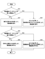
第1の実施形態では、動画像処理プログラムが、専用のハードウェアである符号化回路207により符号化のために生成されたデータを用いて、CPU204の処理により特徴データを検出する例について説明した。第2の実施形態では、端末10から受信した動画像のデータサイズ、または検出対象の特徴データの種別に応じて、当該動画像を、専用の回路である符号化回路207により符号化するか、動画像処理プログラムがCPU204の処理により符号化するか等を切り替える例について説明する。
第1の実施形態では、動画像処理プログラムが、専用のハードウェアである符号化回路207により符号化のために生成されたデータを用いて、CPU204の処理により特徴データを検出する例について説明した。第2の実施形態では、端末10から受信した動画像のデータサイズ、または検出対象の特徴データの種別に応じて、当該動画像を、専用の回路である符号化回路207により符号化するか、動画像処理プログラムがCPU204の処理により符号化するか等を切り替える例について説明する。
例えば、符号化回路207が、フレームの解像度が比較的高い高精細な動画像に特化した回路であり、解像度が低い動画像に対しては、符号化回路207で処理するよりも、CPU204を用いてプログラムで処理した方が速い場合であるとする。または、例えば、検出対象の特徴データの種別が、符号化回路207の実装によって生成されないデータを用いる必要があり、CPU204を用いてプログラムによって符号化する場合は当該データが生成される場合であるとする。これらのような場合においても、第2の実施形態によれば、符号化のために生成されたデータを用いて、所定の検出対象に関するデータを動画像から検出する処理を行うため、当該処理を比較的高速に行うことができる。
なお、第2の実施形態は一部を除いて第1の実施形態と同様であるため、適宜説明を省略する。以下では、第1の実施形態と共通する部分については説明を省略し、異なる部分についてのみ説明する。なお、第2の実施形態に記載の内容は、第1の実施形態にも適用可能である。
<処理>
次に、図11を参照し、第2の実施形態に係る動画像処理装置20の処理について説明する。図11は、第2の実施形態に係る動画像処理装置20の処理の一例を示すフローチャートである。
次に、図11を参照し、第2の実施形態に係る動画像処理装置20の処理について説明する。図11は、第2の実施形態に係る動画像処理装置20の処理の一例を示すフローチャートである。
ステップS21において、制御部26は、端末10から受信した動画像のデータサイズ(フレームの解像度)が第1の閾値以下であるか否かを判定する。
第1の閾値以下である場合(ステップS21でYES)、復号部21は、CPU204を用いた動画像処理プログラムの処理により、端末10から受信した動画像を復号し(ステップS22)、後述するステップS24の処理に進む。
第1の閾値以下でない場合(ステップS21でNO)、復号部21は、復号回路206の処理により、端末10から受信した動画像を復号する(ステップS23)。
続いて、制御部26は、端末10から受信した動画像のデータサイズが第2の閾値以下であるか否かを判定する(ステップS24)。
第2の閾値以下である場合(ステップS24でYES)、符号化部22は、CPU204を用いた動画像処理プログラムの処理により、端末10から受信して復号部21により復号された動画像を符号化し(ステップS25)、処理を終了する。
第2の閾値以下でない場合(ステップS24でNO)、符号化部22は、符号化回路207の処理により、端末10から受信して復号部21により復号された動画像を符号化し(ステップS26)、処理を終了する。
<変形例>
上述した例では、ステップS21、及びステップS24において、端末10から受信した動画像のデータサイズに基づいて判定を行う例について説明したが、ステップS21、及びステップS24の少なくとも一方において、検出対象の特徴データの種別に応じて当該判定を行うようにしてもよい。
上述した例では、ステップS21、及びステップS24において、端末10から受信した動画像のデータサイズに基づいて判定を行う例について説明したが、ステップS21、及びステップS24の少なくとも一方において、検出対象の特徴データの種別に応じて当該判定を行うようにしてもよい。
<その他>
従来、専用のハードウェアにより動画像からの検出処理を行う場合、検出のロジック等を後から変更できないという問題がある。上述した実施形態によれば、トランスコーダである動画像処理装置20が、ソフトウェアの処理により動画像からの検出処理を行うため、検出のロジック等を変更することができる。
従来、専用のハードウェアにより動画像からの検出処理を行う場合、検出のロジック等を後から変更できないという問題がある。上述した実施形態によれば、トランスコーダである動画像処理装置20が、ソフトウェアの処理により動画像からの検出処理を行うため、検出のロジック等を変更することができる。
上述した実施形態は、画像から人を認識する監視カメラシステム、店舗において顧客が商品を手に取ったか、当該商品を購入したか等を分析するデジタルマーケティングシステム、IP配信システム、被写体の情報を動画像に重畳して表示するAR/VRシステム等にも適用できる。
以上、本発明の実施例について詳述したが、本発明は斯かる特定の実施形態に限定されるものではなく、特許請求の範囲に記載された本発明の要旨の範囲内において、種々の変形・変更が可能である。
動画像処理装置20の各機能部は、例えば1以上のコンピュータにより構成されるクラウドコンピューティングにより実現されていてもよい。また、動画像処理装置20、及びサーバ30を一体の装置として構成してもよい。動画像処理装置20、及び端末10を一体の装置として構成してもよい。この場合、動画像処理装置20は、動画像の復号処理をしなくともよい。端末10またはサーバ30の各機能部のうち少なくとも一部を、動画像処理装置20が有するようにしてもよい。
なお、サーバ30は、「情報処理装置」の一例である。
1 通信システム
10 端末
20 動画像処理装置
21 復号部
22 符号化部
23 取得部
24 検出部
25 出力部
26 制御部
202 補助記憶装置
203 メモリ装置
204 CPU
205 インタフェース装置
206 復号回路
207 符号化回路
208 メモリ
30 サーバ
31 復号部
32 データ処理部
33 表示制御部
10 端末
20 動画像処理装置
21 復号部
22 符号化部
23 取得部
24 検出部
25 出力部
26 制御部
202 補助記憶装置
203 メモリ装置
204 CPU
205 インタフェース装置
206 復号回路
207 符号化回路
208 メモリ
30 サーバ
31 復号部
32 データ処理部
33 表示制御部
Claims (11)
- 動画像を符号化する符号化部と、
前記符号化部による前記動画像が圧縮されて符号化される処理に用いられるデータを取得する取得部と、
前記取得部により取得されたデータに基づいて、前記動画像の特徴を示す特徴データを前記動画像から検出する検出部と、
前記符号化部により前記動画像が符号化されたデータと、前記検出部により検出された前記特徴データとを出力する出力部と、
を有する動画像処理装置。 - 前記動画像処理装置は、第1の方式で符号化されている前記動画像を復号する復号部を有し、
前記符号化部は、前記第1の方式とは異なる第2の方式により、前記復号部により復号された前記動画像を符号化する、
請求項1に記載の動画像処理装置。 - 前記取得部は、符号化部により符号化処理が行われる単位であるブロックのデータ、または前記動画像に含まれるフレームの縮小画像を取得する、
請求項1または2に記載の動画像処理装置。 - 前記符号化部により前記動画像が圧縮されて符号化される処理に用いられるデータは、符号化部により符号化処理が行われる単位であるブロックのデータ、前記動画像に含まれるフレームの縮小画像、及び前記動画像において連続する複数のフレーム間の変化を示すデータの少なくとも一つを含む、
請求項1乃至3のいずれか一項に記載の動画像処理装置。 - 前記検出部は、前記ブロックのサイズが所定値以下の領域、及び連続する複数のフレーム間で変化した領域の少なくとも一つを検索し、前記特徴データを検出する、
請求項4に記載の動画像処理装置。 - 前記特徴データは、検出対象の物体の領域、及び前記物体の動きの少なくとも一つを含む、
請求項1乃至5のいずれか一項に記載の動画像処理装置。 - 前記出力部は、前記符号化部により符号化された前記動画像のフレームに対応付けて、前記動画像において当該フレームに対応する画像から前記検出部により検出された前記特徴データを出力する、
請求項1乃至6のいずれか一項に記載の動画像処理装置。 - 前記符号化部は、前記動画像が圧縮されて符号化される処理に用いられるデータをメモリに転送し、
前記検出部は、前記メモリに記憶されたデータに基づいて、前記動画像の特徴を示す特徴データを前記動画像から検出する、
請求項1乃至7のいずれか一項に記載の動画像処理装置。 - 前記動画像処理装置は、
符号化する前記動画像のフレームの解像度、及び検出対象の特徴データの種別に応じて、CPU(Central Processing Unit)で前記動画像を符号化するか、専用の回路で前記動画像を符号化するかを切り替える、
請求項1乃至8のいずれか一項に記載の動画像処理装置。 - 動画像処理装置と、情報処理装置とを有し、
前記動画像処理装置は、
動画像を符号化する符号化部と、
前記符号化部による前記動画像が圧縮されて符号化される処理に用いられるデータを取得する取得部と、
前記取得部により取得されたデータに基づいて、前記動画像の特徴を示す特徴データを前記動画像から検出する検出部と、
前記符号化部により前記動画像が符号化されたデータと、前記検出部により検出された前記特徴データとを前記情報処理装置に出力する出力部と、
を有し、
前記情報処理装置は、
前記動画像処理装置から受信した前記動画像を復号する復号部と、
前記動画像に、前記特徴データに応じた情報を重畳または付加させて表示させる表示制御部と、
を有する動画像処理システム。 - 動画像処理装置が、
動画像を符号化するステップと、
前記動画像が圧縮されて符号化される処理に用いられるデータを取得するステップと、
取得されたデータに基づいて、前記動画像の特徴を示す特徴データを前記動画像から検出するステップと、
前記動画像が符号化されたデータと、検出された前記特徴データとを出力するステップと、
を実行する動画像処理方法。
Priority Applications (4)
| Application Number | Priority Date | Filing Date | Title |
|---|---|---|---|
| JP2019549757A JPWO2019082318A1 (ja) | 2017-10-25 | 2017-10-25 | 動画像処理装置、動画像処理システム、及び動画像処理方法 |
| CN201780096169.3A CN111279388A (zh) | 2017-10-25 | 2017-10-25 | 动态图像处理装置、动态图像处理系统、以及动态图像处理方法 |
| PCT/JP2017/038582 WO2019082318A1 (ja) | 2017-10-25 | 2017-10-25 | 動画像処理装置、動画像処理システム、及び動画像処理方法 |
| US16/853,248 US20200252637A1 (en) | 2017-10-25 | 2020-04-20 | Moving image processor, moving image processing system, and moving image processing method |
Applications Claiming Priority (1)
| Application Number | Priority Date | Filing Date | Title |
|---|---|---|---|
| PCT/JP2017/038582 WO2019082318A1 (ja) | 2017-10-25 | 2017-10-25 | 動画像処理装置、動画像処理システム、及び動画像処理方法 |
Related Child Applications (1)
| Application Number | Title | Priority Date | Filing Date |
|---|---|---|---|
| US16/853,248 Continuation US20200252637A1 (en) | 2017-10-25 | 2020-04-20 | Moving image processor, moving image processing system, and moving image processing method |
Publications (1)
| Publication Number | Publication Date |
|---|---|
| WO2019082318A1 true WO2019082318A1 (ja) | 2019-05-02 |
Family
ID=66246276
Family Applications (1)
| Application Number | Title | Priority Date | Filing Date |
|---|---|---|---|
| PCT/JP2017/038582 WO2019082318A1 (ja) | 2017-10-25 | 2017-10-25 | 動画像処理装置、動画像処理システム、及び動画像処理方法 |
Country Status (4)
| Country | Link |
|---|---|
| US (1) | US20200252637A1 (ja) |
| JP (1) | JPWO2019082318A1 (ja) |
| CN (1) | CN111279388A (ja) |
| WO (1) | WO2019082318A1 (ja) |
Citations (4)
| Publication number | Priority date | Publication date | Assignee | Title |
|---|---|---|---|---|
| JP2000299664A (ja) * | 1999-04-14 | 2000-10-24 | Casio Comput Co Ltd | データ処理装置及びデータ処理プログラムを記憶した記憶媒体 |
| JP2012015652A (ja) * | 2010-06-29 | 2012-01-19 | Canon Inc | 画像処理装置及びその制御方法並びにプログラム |
| JP2012022370A (ja) * | 2010-07-12 | 2012-02-02 | Hitachi Kokusai Electric Inc | 監視システムおよび監視方法 |
| WO2016143067A1 (ja) * | 2015-03-10 | 2016-09-15 | 三菱電機株式会社 | 映像解析装置 |
Family Cites Families (8)
| Publication number | Priority date | Publication date | Assignee | Title |
|---|---|---|---|---|
| JP3982615B2 (ja) * | 2002-03-11 | 2007-09-26 | 株式会社Kddi研究所 | 符号化動画像データの方式変換装置 |
| KR100990829B1 (ko) * | 2002-11-01 | 2010-10-29 | 파나소닉 주식회사 | 동화상 부호화 방법 및 동화상 복호화 방법 |
| CN1717939A (zh) * | 2003-02-19 | 2006-01-04 | 松下电器产业株式会社 | 图像解码装置、图像编码装置及其方法 |
| JP2007336277A (ja) * | 2006-06-15 | 2007-12-27 | Nec Corp | 動画像符号化復号化方法、符号化復号化装置及び動画像符号化復号化プログラム |
| JP2011097572A (ja) * | 2009-09-29 | 2011-05-12 | Canon Inc | 動画像符号化装置 |
| WO2012014472A1 (ja) * | 2010-07-29 | 2012-02-02 | パナソニック株式会社 | 動画像符号化方法、動画像符号化装置、動画像復号方法、及び動画像復号装置 |
| PL3419290T3 (pl) * | 2011-06-30 | 2021-05-31 | JVC Kenwood Corporation | Urządzenie do kodowania obrazu, sposób kodowania obrazu, program do kodowania obrazu, urządzenie do dekodowania obrazu, sposób dekodowania obrazu i program do dekodowania obrazu |
| LT3416387T (lt) * | 2011-11-02 | 2024-01-10 | Tagivan Ii Llc | Vaizdo kodavimo būdas ir vaizdo kodavimo įrenginys |
-
2017
- 2017-10-25 WO PCT/JP2017/038582 patent/WO2019082318A1/ja active Application Filing
- 2017-10-25 CN CN201780096169.3A patent/CN111279388A/zh active Pending
- 2017-10-25 JP JP2019549757A patent/JPWO2019082318A1/ja active Pending
-
2020
- 2020-04-20 US US16/853,248 patent/US20200252637A1/en not_active Abandoned
Patent Citations (4)
| Publication number | Priority date | Publication date | Assignee | Title |
|---|---|---|---|---|
| JP2000299664A (ja) * | 1999-04-14 | 2000-10-24 | Casio Comput Co Ltd | データ処理装置及びデータ処理プログラムを記憶した記憶媒体 |
| JP2012015652A (ja) * | 2010-06-29 | 2012-01-19 | Canon Inc | 画像処理装置及びその制御方法並びにプログラム |
| JP2012022370A (ja) * | 2010-07-12 | 2012-02-02 | Hitachi Kokusai Electric Inc | 監視システムおよび監視方法 |
| WO2016143067A1 (ja) * | 2015-03-10 | 2016-09-15 | 三菱電機株式会社 | 映像解析装置 |
Also Published As
| Publication number | Publication date |
|---|---|
| JPWO2019082318A1 (ja) | 2020-11-19 |
| US20200252637A1 (en) | 2020-08-06 |
| CN111279388A (zh) | 2020-06-12 |
Similar Documents
| Publication | Publication Date | Title |
|---|---|---|
| Sitara et al. | Digital video tampering detection: An overview of passive techniques | |
| JP4763422B2 (ja) | イントラ予測装置 | |
| TWI578757B (zh) | 場景形式之視訊串流編碼 | |
| JP6636615B2 (ja) | 動きベクトル場の符号化方法、復号方法、符号化装置、および復号装置 | |
| JP7157152B2 (ja) | 画像コーディングシステムにおけるサブブロック単位の動き予測に基づく画像デコーディング方法及び装置 | |
| JP2007116351A (ja) | 画像予測符号化装置、画像予測復号装置、画像予測符号化方法、画像予測復号方法、画像予測符号化プログラム、及び画像予測復号プログラム | |
| JP2010136032A (ja) | 映像監視システム | |
| US11310514B2 (en) | Encoding method and apparatus using non-encoding region, block-based encoding region, and pixel-based encoding region | |
| JP2008505562A (ja) | Mpegビデオストリーム内の動きを検出する方法及び装置 | |
| KR20100095914A (ko) | 채널 상관 관계를 이용한 영상 부호화/복호화 장치 및 방법과 그를 위한 컴퓨터로 읽을 수 있는 기록매체 | |
| WO2019128716A1 (zh) | 图像的预测方法、装置及编解码器 | |
| TWI521473B (zh) | 影像分析裝置、方法及電腦可讀取媒體 | |
| US11495023B2 (en) | Moving image analysis apparatus, system, and method | |
| KR20180021942A (ko) | 보안 카메라용 영상 코덱에서 블록 분할 정보 전송 방법 및 장치 | |
| JP6678357B2 (ja) | ビデオ符号化システムにおける動きベクトルの選択及び予測方法 | |
| US20230188679A1 (en) | Apparatus and method for transmitting images and apparatus and method for receiving images | |
| US20130223525A1 (en) | Pixel patch collection for prediction in video coding system | |
| WO2023011420A1 (zh) | 编解码方法和装置 | |
| JP2014514808A (ja) | 画像ブロックを再構成および符号化する方法 | |
| WO2019082318A1 (ja) | 動画像処理装置、動画像処理システム、及び動画像処理方法 | |
| Wang et al. | Content-based image retrieval using H. 264 intra coding features | |
| JP6190103B2 (ja) | 動画像符号化装置、動画像符号化方法およびプログラム | |
| KR20020067286A (ko) | 객체기반 영상 감시시스템 | |
| RU2816199C1 (ru) | Кодирование видео или изображений на основе внутриблочного кодирования | |
| KR101323886B1 (ko) | 분산처리 기반의 물체 추적장치 및 추적방법 |
Legal Events
| Date | Code | Title | Description |
|---|---|---|---|
| 121 | Ep: the epo has been informed by wipo that ep was designated in this application |
Ref document number: 17929542 Country of ref document: EP Kind code of ref document: A1 |
|
| ENP | Entry into the national phase |
Ref document number: 2019549757 Country of ref document: JP Kind code of ref document: A |
|
| NENP | Non-entry into the national phase |
Ref country code: DE |
|
| 122 | Ep: pct application non-entry in european phase |
Ref document number: 17929542 Country of ref document: EP Kind code of ref document: A1 |