WO2019072148A1 - 实现气压控制和离子解离的质谱仪 - Google Patents
实现气压控制和离子解离的质谱仪 Download PDFInfo
- Publication number
- WO2019072148A1 WO2019072148A1 PCT/CN2018/109355 CN2018109355W WO2019072148A1 WO 2019072148 A1 WO2019072148 A1 WO 2019072148A1 CN 2018109355 W CN2018109355 W CN 2018109355W WO 2019072148 A1 WO2019072148 A1 WO 2019072148A1
- Authority
- WO
- WIPO (PCT)
- Prior art keywords
- ion trap
- linear ion
- ions
- gas pressure
- linear
- Prior art date
Links
Images


Classifications
-
- H—ELECTRICITY
- H01—ELECTRIC ELEMENTS
- H01J—ELECTRIC DISCHARGE TUBES OR DISCHARGE LAMPS
- H01J49/00—Particle spectrometers or separator tubes
-
- H—ELECTRICITY
- H01—ELECTRIC ELEMENTS
- H01J—ELECTRIC DISCHARGE TUBES OR DISCHARGE LAMPS
- H01J49/00—Particle spectrometers or separator tubes
- H01J49/26—Mass spectrometers or separator tubes
- H01J49/34—Dynamic spectrometers
- H01J49/42—Stability-of-path spectrometers, e.g. monopole, quadrupole, multipole, farvitrons
Definitions
- the invention relates to the technical field of mass spectrometer analysis, in particular to a mass spectrometer for realizing air pressure control and ion dissociation.
- a mass spectrometer is an instrument for analyzing the mass-to-charge ratio information of charged particles, centered on an ion source, a mass analyzer, and an ion detector.
- Cascade mass spectrometry is an effective chemical analysis method for mass spectrometers. It plays an important role in determining molecular structure, detecting unknown biomolecules, and determining specific chemical substances in complex mixture samples.
- the basic process of cascade mass spectrometry is By applying energy to the sample ions to increase the internal energy of the ions, the internal chemical bonds of the ions are broken by the excitation of energy, and mass spectra of different mass-to-charge ratio fragment ions are obtained.
- the molecular structure of the sample to be tested is estimated by analyzing the fragment ions.
- the composition of matter, etc. provides an effective way for the top-down analysis of mass spectrometry instruments, so cascade mass spectrometry plays a crucial role in the application of mass spectrometers.
- ETD Electron Transfer Dissociation
- CID Collision Induced Dissociation
- SID Surface Induced Dissociation
- IRMPD Infrared Multiphoton Dissociation
- UVPD Ultraviolet Photodissociation
- the cleavage of ions is achieved by chemical excitation; collision-induced dissociation and surface collision-induced dissociation are the collisions between the ions to be analyzed and the neutral matter, and the kinetic energy of the ions during the collision. When converted to internal energy, when the internal energy increases to a certain extent, ion dissociation occurs.
- collision-induced dissociation is achieved by multiple collisions of ions with neutral gas atoms or molecules.
- IRMPD Infrared Multiphoton Dissociation
- UV photodissociation Ultraviolet Photodissociation
- UVPD belongs to the way of photoexcitation to achieve ion dissociation. The difference is that the infrared photon energy is low, and it is necessary to absorb multiple infrared photons to achieve dissociation. The energy of ultraviolet single photon is higher, and single photon can realize ion.
- CID collision-induced dissociation
- a collision reaction cell for collision-induced dissociation is designed in the mass spectrometer of the above type, and a neutral gas colliding with the sample ion to be analyzed is introduced into the collision reaction cell, and the collision reaction cell is controlled by controlling the gas flow rate.
- Mass spectrometers are divided into many different types according to their quality analyzers, and each mass analyzer has different characteristics.
- the more commonly used mass analyzers are Quadrupole Analysers and three-dimensional ions. 3D Ion Trap Analysers, Linear Ion Trap Analysers, Orbitrap Analysers, TOF Analysers, Fourier Transform Various types of ion cyclotron resonance mass analyzers (FTICR Analysers).
- mass spectrometers combine a variety of mass analyzers, and the analytical advantages of different mass analyzers can further improve the analytical performance of the combined mass spectrometer.
- the combinatorial mass spectrometers of the common multi-quality analyzers have triple four-level Mass spectrometer, which uses a three-stage tandem four-stage mass analyzer. Each mass analyzer has different functions.
- the combined mass spectrometer can realize many complex analysis modes for analyzing complex biological samples.
- Another commonly used combined mass spectrometer is a quadrupole mass analyzer plus a time-of-flight mass spectrometer mass spectrometer that can pass quadrupole mass
- the analyzer selects ions of a specific mass-to-charge ratio, and the selected ions are subjected to cascade mass spectrometry and then entered into a time-of-flight mass spectrometer for high-resolution mass spectrometry, which is a commonly used analytical method for qualitative analysis of sample components.
- the mass spectrometer introduced in this patent uses Discontinuous Atmospheric Pressure Interface (DAPI), which uses this interface to connect the mass spectrometer vacuum chamber to the atmospheric pressure ion source.
- DAPI Discontinuous Atmospheric Pressure Interface
- the non-continuous injection is first controlled. The mouth is opened, and the sample ions and air molecules to be analyzed are introduced into the vacuum chamber of the mass spectrometer in a short time. After the injection process is finished, the interface is controlled to be closed; since a large amount of air molecules enter the vacuum chamber after opening the injection interface, the internal pressure of the vacuum chamber It will rise rapidly. Under the action of the mass spectrometer vacuum system, the pressure in the vacuum chamber will gradually decrease.
- DAPI Discontinuous Atmospheric Pressure Interface
- This process is the injection and pressure change of the discontinuous injection mass spectrometer; the mass spectrometer using the discontinuous injection method can be reduced.
- the vacuum chamber maintains a high vacuum, no external gas enters, and the vacuum system can be operated at a lower power consumption for sample analysis.
- the discontinuous injection interface is opened for a short period of time to ensure the introduction of sample ions to be analyzed. Close the sample after vacuum system interface role, the vacuum chamber pressure gradually decreases.
- the mass spectrometer designed in this way has a pumping speed of a vacuum system that is small, and runs at a lower power consumption most of the time, so the interface mode has its outstanding features on a miniaturized portable mass spectrometer. The advantages.
- the medium mass spectrometer uses a series bilinear ion trap structure. Some of the mass spectrometer scan modes require multiple ion transports between the ion traps, and the ion transport efficiency varies greatly under different gas pressures, and requires ion transport. The collision-induced dissociation of ions is achieved during the process, and the above ion manipulation mode cannot be realized during the process of gradually decreasing the pressure in the vacuum chamber.
- the present invention aims to solve at least one of the above technical problems to some extent.
- the present invention proposes a mass spectrometer that realizes gas pressure control and ion dissociation, and the mass spectrometer that realizes gas pressure control and ion dissociation can improve ion by controlling local gas pressure inside the ion trap or controlling internal gas pressure of the entire vacuum chamber.
- the axial transmission efficiency while in the process of cascade mass spectrometry, makes the internal pressure of the ion trap relatively stable.
- the mass spectrometer for achieving gas pressure control and ion dissociation can also realize the axial transmission of ions by loading different voltages on the first linear ion trap and the second linear ion trap, and the ions collide with the gas during the transmission process.
- the dissociation process is simple and easy to implement.
- a mass spectrometer for achieving gas pressure control and ion dissociation includes: a cavity structure defining a vacuum chamber having an inlet, wherein the vacuum chamber is provided with a first linear ion in series a well and a second linear ion trap, the first linear ion trap and the second linear ion trap being formed with inter-connected ion channels including a trap region on both sides and a collision region in the middle, the ion An inlet end of the channel is disposed opposite to the inlet, a front end of the first linear ion trap is provided with a first electrode, and a rear end of the second linear ion trap is provided with a second electrode, in the first linear a third electrode is disposed between the ion trap and the second linear ion trap; a vacuuming device is disposed on the cavity structure to evacuate the vacuum chamber; an ion detector, the ion detecting The device is disposed in the vacuum chamber for mass analysis of ions in the ion channel;
- a mass spectrometer for realizing air pressure control and ion dissociation is provided with a gas pressure adjusting device for adjusting the pressure in a vacuum chamber on a cavity structure, so that the gas pressure in the vacuum chamber is maintained within a certain range, and the ion is improved.
- Axial transmission efficiency by applying a different voltage to the first linear ion trap and the second linear ion trap, forming a voltage difference between the first linear ion trap and the second linear ion trap to drive ions along the ion channel axis
- the gas is introduced into the collision region through the gas guiding device to realize the induced dissociation of the ions, and the mass spectrometer for realizing the gas pressure control and the ion dissociation is relatively simple in structure, and the dissociation is convenient and easy to implement.
- mass spectrometer implementing the air pressure control and the ion dissociation according to an embodiment of the present invention may further have the following additional technical features:
- the air pressure adjusting device is for adjusting the air pressure in the second linear ion trap.
- the air pressure adjusting device includes: a first conduit, one end of the first conduit extends into the second linear ion trap; and the second conduit, the second conduit Connecting with the other end of the first pipeline forms an intake passage; a pulse control valve for turning on or off the intake passage.
- the air pressure adjusting device adjusts the air pressure in the second linear ion trap by means of a pulse air intake.
- the second conduit has a length of 50 mm stainless steel tubing having an inner diameter of 0.01 inches.
- the air pressure adjusting device adjusts the air pressure in the second linear ion trap by a continuous air intake mode.
- the second conduit has a length of 250 mm stainless steel tubing with an inner diameter of 0.005 inches.
- the air pressure adjusting device includes: a third pipeline, an outlet end of the third pipeline extends into the vacuum chamber; a buffer gas passage, the buffer gas passage and the first The inlet ends of the three pipelines communicate to form an intake passage; the first controllable valve, the first controllable valve is disposed at a junction of the third conduit and the buffer gas passage; the second controllable valve, the second A controllable valve is provided at the inlet end of the buffer gas path.
- the step of adjusting the air pressure in the vacuum chamber by the air pressure adjusting device is as follows: closing the inlet, opening the first controllable valve, and closing the second controllable valve for a duration T1,
- the gas of the buffer gas path is entered into the vacuum chamber; the inlet is opened, the sample ions to be analyzed are introduced into the first linear ion trap; the inlet is closed for a duration T2; the second controllable valve is opened for a duration T3, the ion
- the axial transmission is carried out into the second linear ion trap and the ions are subjected to tandem mass spectrometry; the first controllable valve is closed, and after the duration T4, the second controllable valve is closed; for a duration T5, mass analysis is performed to obtain a mass spectrum.
- the injection port is provided with a discontinuous injection assembly comprising: an inlet stainless steel metal tube and an outlet stainless steel metal tube, the inlet stainless steel metal tube and the outlet stainless steel
- the metal tube is connected by an insulating rubber tube, and the insulating rubber tube is provided with a pinch valve.
- the gas filled inside the second linear ion trap by the air pressure adjusting device is one of air, nitrogen, helium and argon.
- ions are axially transmitted from the first linear ion trap to the second linear ion trap.
- ions are axially transmitted from the second linear ion trap toward the first linear ion trap.
- the voltage of the first linear ion trap is greater than the voltage of the second linear ion trap during the first transmission period, and at this time, the ions are forwardly axially transmitted in the ion channel;
- the voltage of the first linear ion trap is less than the voltage of the second linear ion trap, at which time ions are reversely axially transmitted within the ion channel.
- the ion dissociation process of the mass spectrometer implementing the gas pressure control and the ion dissociation comprises the following steps: S100: pairing the first electrode, the second electrode, the first linear ion trap, and the second linear ion trap And applying a voltage to the third electrode; S200: introducing and trapping the ions in the first linear ion trap, performing mass spectrometry on the ions in the trapped region of the first linear ion trap; S300: controlling the voltage of the first linear ion trap to be greater than The voltage of the two-line ion trap is transmitted axially into the second linear ion trap, and a gas is introduced into the collision region during the transmission to cause the ions to collide with the gas in the collision region to generate fragment ions; S400: stop the ventilation, The ions in the trapped region of the second linear ion trap are subjected to mass spectrometry; S500: adjusting the voltages of the first linear ion trap and the second linear ion trap And applying a voltage
- the gas causes the ions to collide with the gas in the collision region to generate fragment ions; S600: stop the aeration, perform mass spectrometry on the ions in the trapped region of the first linear ion trap; repeat the cycle steps S100-S600 multiple times to realize the pair of ions Multi-stage fragmentation and multi-stage mass spectrometry were performed.
- step S200 further comprises: screening out ions of a mass-to-charge ratio into the first linear ion trap.
- step S300 further includes: screening another ion of mass to charge ratio into the second linear ion trap.
- step S500 further includes: screening another ion of mass to charge ratio into the first linear ion trap.
- Figure 1 is a graph showing the relationship between the gas pressure and the mean molecular free path
- Figure 2 is a graph showing the relationship between ion transport efficiency and gas pressure
- FIG. 3 is a schematic structural view of a mass spectrometer implementing gas pressure control and ion dissociation according to an embodiment of the present invention
- FIG. 4 is a view showing changes in the pressure in the vacuum chamber in the case where the second linear ion trap is not in intake, pulsed intake, or continuous intake;
- Figure 5 shows the relationship between ion transport efficiency and time after the inlet is closed in three cases of no intake, pulsed intake and continuous intake.
- FIG. 6 is a schematic structural view of a mass spectrometer implementing gas pressure control and ion dissociation according to another embodiment of the present invention.
- FIG. 7 is a flow chart showing the operation of a mass spectrometer for achieving gas pressure control and ion dissociation according to another embodiment of the present invention.
- Figure 8 is a graph showing the relationship between gas pressure and time for a mass spectrometer implementing gas pressure control and ion dissociation according to another embodiment of the present invention.
- FIG. 9 is a graph showing the relationship between gas pressure and time of a mass spectrometer for achieving gas pressure control and ion dissociation according to another embodiment of the present invention.
- FIG. 10 is a schematic structural view of a mass spectrometer for implementing gas pressure control and ion dissociation in some embodiments of the present invention
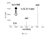
- Figure 11a is a graph showing the degree of collision-induced dissociation of reserpine ions when the voltage difference between the first and second linear ion traps is 20V;
- Figure 11b is a graph showing the degree of collision-induced dissociation of reserpine ions when the voltage difference between the first and second linear ion traps is 30V;
- Figure 11c is a graph showing the degree of collision-induced dissociation of reserpine ions when the voltage difference between the first and second linear ion traps is 40V;
- Figure 12 is a schematic diagram showing the axial transmission of one mass-to-charge ratio ion into another linear ion trap from one of the linear ion traps, and ion cleavage occurs;
- Figure 13a is a mass spectrum obtained after dissociation of ions of mass-to-charge ratio 527 into the second linear ion trap;
- Figure 13b is a mass spectrum obtained after the ions of the mass-to-charge ratio 365 (the fragment ions of 527 ions) are axially dissociated into the first linear ion trap;
- Figure 13c is a mass spectrum obtained after the ion-to-charge ratio of the mass-to-charge ratio 275 (the fragment ion of 365 ions) is dissociated into the second linear ion trap;
- Figure 14 is a flow diagram of ionic dissociation of a mass spectrometer implementing gas pressure control and ion dissociation in accordance with some embodiments of the present invention.
- a mass spectrometer 100 that implements gas pressure control and ion dissociation
- first linear ion trap 1 a first linear ion trap 1; a second linear ion trap 2; a trap region 21; a collision region 22;
- Non-continuous injection assembly 3 outlet stainless steel metal tube 31; pinch valve 32; inlet stainless steel metal tube 33; insulating rubber tube 34;
- First electrode 4 third electrode 5; second electrode 6;
- Ion detector 7 cavity structure 8; vacuum chamber 81;
- Air pressure adjusting device 20
- Vacuuming device 12 third conduit 13; buffer gas passage 14; first controllable valve 15; second controllable valve 17.
- the mass spectrometer is an instrument for detecting and analyzing the ion mass-to-charge ratio information of the sample.
- the mass spectrometer in the related art analyzes the sample ions, the ion transmission efficiency is low, thereby affecting the experimental effect.
- Figure 1 is a graph showing the relationship between the gas pressure and the mean molecular free path in a mass spectrometer with a series bilinear ion trap.
- the first linear ion trap and the second linear ion trap, the sample ions to be analyzed are first introduced into the first linear ion trap and then axially transferred into the second linear ion trap, as shown in FIG.
- the corresponding mean molecular free path is 54 mm; due to the greater kinetic energy of the ions as they travel axially in the first linear ion trap, when the ions are trapped in the second linear ion trap, Under the action of the RF electric field and the DC electric field, the ions collide with the neutral molecules in the air to reduce the kinetic energy of the ions, so that the second linear ion trap can trap the ions near the axis of the second linear ion trap. Complete the subsequent cascade mass spectrometry plasma operation.
- the average molecular free path in the second linear ion trap will be greater than 54 mm, that is, the ions need to move more than 54 mm to cause a collision.
- the kinetic energy of the ions is reduced, and in the process, most of the ions have left the stable region of the second linear ion trap without colliding, so that the ions can not be effectively mass spectrometrically analyzed.
- the inventors conducted experiments on the relationship between the transmission efficiency of reserpine ions and the pressure in the vacuum chamber.
- the experimental procedure is as follows.
- the non-continuous injection assembly is opened, and the sample to be analyzed is trapped in the first linear ion trap, and then passed.
- the axial selective transmission transfers ions from the first linear ion trap to the second linear ion trap, performs ion axial transmission at different gas pressure points in the vacuum chamber, and analyzes the ion intensity in the second linear ion trap by mass spectrometry. Signal value. It can be concluded from Fig.
- a mass spectrometer 100 that implements gas pressure control and ion dissociation in accordance with an embodiment of the present invention is described below with reference to FIGS. 3 through 14.
- the mass spectrometer 100 that implements gas pressure control and ion dissociation can generally include a cavity structure 8, a gas pressure regulating device 20, and a vacuuming device 12.
- the cavity structure 8 defines a vacuum chamber 81 having an inlet, and a first linear ion trap 1 and a second linear ion trap 2 connected in series, a first linear ion trap 1 and a second linear ion trap are disposed in the vacuum chamber 81. 2 forming an ion channel communicating with each other, the inlet end of the ion channel is opposite to the inlet, the front end of the first linear ion trap 1 is provided with a first electrode 4, and the rear end of the second linear ion trap 2 is provided with a second The electrode 6, a third electrode 5 is provided between the first linear ion trap 1 and the second linear ion trap 2.
- the air pressure adjusting device 20 is disposed on the cavity structure 8 for adjusting the air pressure in the vacuum chamber 81.
- the vacuuming device 12 is disposed on the cavity structure 8 to evacuate the vacuum chamber 81.
- the ion detector 7 is disposed in the vacuum chamber 81 for mass analysis of ions in the ion channel.
- the inlet is a discontinuous injection interface, that is, the sample ions to be analyzed are intermittently transferred into the ion channel through the inlet.
- the vacuuming device 12 has a molecular pump and a diaphragm pump connected in series to each other to effect vacuuming of the vacuum chamber 81.
- the mass spectrometer 100 for achieving gas pressure control and ion dissociation adopts a series bilinear ion trap structure, and the operation process of the mass spectrometer 100 for achieving gas pressure control and ion dissociation is as follows.
- the vacuum chamber 81 and the external atmospheric pressure are connected through the inlet. Environment, controlling the inlet to introduce the sample ions to be analyzed, the sample ions entering the vacuum chamber 81 are trapped in the first linear ion trap 1, and the ions are sequentially transferred to the second linear ion trap 2 by axial selective transmission. Do cascade analysis.
- the different mass-to-charge ratio ion signals are amplified by the ion detector 7, and the mass spectrometer 100 control system that realizes the gas pressure control and the ion dissociation collects the signal into a computer to obtain a mass spectrum of the sample to be analyzed.
- the first electrode 4, the second electrode 6, and the third electrode 5 may be DC electrodes.
- the gas pressure in the vacuum chamber 81 can be adjusted by the gas pressure adjusting device so that the gas pressure in the vacuum chamber 81 is maintained in a stable range, for example, in the vacuum chamber 81.
- a preset value for example, 1 ⁇ 10 -3 Torr
- the vacuum chamber 81 is pressurized, and when the air pressure in the vacuum chamber 81 is higher than a preset value (for example, 1 ⁇ 10 -2 Torr), the vacuum is applied.
- the chamber 81 is depressurized, thereby ensuring that the pressure of the vacuum chamber 81 is maintained within a certain pressure range, thereby improving the ion transport efficiency.
- the air pressure in the vacuum chamber 81 is maintained by providing the air pressure adjusting device 20 for adjusting the air pressure in the vacuum chamber 81 on the cavity structure 8. In a certain range, the axial transmission efficiency of ions is improved.
- the gas pressure regulating device 20 is used to adjust the gas pressure within the second linear ion trap 2.
- one end of the air pressure adjusting device 20 can extend into the gap formed by the front end of the third electrode 5 and the second linear ion trap 2, and the gap between the electrodes can ensure that the gas enters the inside of the second linear ion trap 2 well.
- the internal pressure of the second linear ion trap 2 is increased, and the air pressure adjusting device 20 controls a small amount of air intake, so that the air pressure at other positions of the vacuum chamber 81 is relatively stable, which facilitates the mass spectrometry operation after the gas pressure is lowered, thereby improving the ion transport efficiency.
- the air pressure adjusting device 20 includes a first conduit 9 and a second conduit 11. One end of the first conduit 9 extends into the vacuum chamber 81 to communicate with the interior of the second linear ion trap 2.
- the second line 11 is connected to the other end of the first line 9, and the second line 11 is provided with a pulse control valve 10.
- the first line 9 of the air pressure adjusting device 20 is in communication with the second linear ion trap 2, and the pulse control valve 10 can control whether the air intake and the intake air are in a manner.
- the air pressure adjusting device 20 can also include a pneumatic valve, and the air pressure valve can be controlled. The amount of intake air thus achieves the purpose of adjusting the internal pressure of the second linear ion trap 2.
- the pulse control valve 10 is controlled by an external trigger signal of a control system of the mass spectrometer 100 that realizes air pressure control and ion dissociation, and the signal can be synchronized with a timing control signal of the mass spectrometer 100 that realizes air pressure control and ion dissociation.
- Fig. 5 is a graph showing the relationship between the ion signal intensity and the injection time of the second linear ion trap 2 non-intake, pulsed intake and continuous intake modes.
- the inlet is closed for 550 ms. Thereafter, if the second linear ion trap 2 is not introduced, the ion intensity will rapidly decrease, that is, the ion transport efficiency is lowered, and only a small amount of ions can be trapped in the second linear ion trap 2.
- the pulsed or continuous intake of the second linear ion trap 2 can increase the ion signal intensity.
- the second line 11 may be composed of a stainless steel tube having an inner diameter of 0.01 inch and a length of 50 mm.
- the buffer gas is introduced into the second linear ion trap 2.
- the pulse control valve 10 is closed to stop the intake, and the ions trapped by the second linear ion trap 2 are subjected to mass spectrometry. Ion intensity signal.
- the second line 11 may be composed of a stainless steel tube having an inner diameter of 0.005 inches and a length of 250 mm. It should be noted that, with the continuous intake control mode, no additional control signal is required, and the buffer gas is always supplied to the mass spectrometer 100 that realizes the air pressure control and the ion dissociation, and is turned off at the end of the analysis program. The intake air and the continuously introduced gas cause a higher local gas pressure in the second linear ion trap 2, which improves the ion transmission efficiency.
- the local air pressure in the second linear ion trap 2 can be increased to ensure a high transmission efficiency of the ions.
- the air pressure in the vacuum chamber 81 is not significantly increased, so that the subsequent mass spectrometry process is not affected.
- the air pressure adjusting device 20 directly adjusts the air pressure in the vacuum chamber 81.
- the air pressure adjusting device 20 includes: a third pipeline 13, a buffer gas passage 14, and a first controllable The valve 15 and the second controllable valve 17, the outlet end of the third line 13 extend into the vacuum chamber 81.
- the buffer gas path 14 communicates with the inlet end of the third line 13 to form an intake passage.
- the first controllable valve 15 is provided at the junction of the third line 13 and the buffer gas path 14.
- the second controllable valve 17 is disposed at the inlet end of the buffer gas passage 14.
- the on/off of the third pipeline is controlled by the first control valve
- the on/off of the buffer gas passage 14 is controlled by the second control valve, wherein the buffer gas passage 14 can directly communicate with the gas cylinder or the atmospheric pressure.
- the inlet is a discontinuous injection interface, that is, the sample ions to be analyzed are intermittently transferred into the ion channel through the inlet.
- the air pressure in the vacuum chamber 81 will rise rapidly, and when the inlet is closed, the air pressure in the vacuum chamber 81 will be lowered again. In order to ensure good ion transmission efficiency, the air pressure can be adjusted.
- the device 20 maintains the pressure of the vacuum chamber 81 at a fixed value, wherein when only one ion is transported and mass spectrometrically analyzed, the gas pressure in the vacuum chamber 81 can have a stable gas pressure, as shown in FIG.
- the gas pressure value of the segment is 4.9 ⁇ 10 -3 Torr; when a plurality of ions are required for transmission and mass spectrometry, the gas pressure in the vacuum chamber 81 can have two or more stable gas pressures, as shown in Fig. 9, two stable gas pressure segments.
- the barometric pressure values are approximately the same.
- the air pressure value of the stable air pressure section can be adjusted by changing the inner diameter and length of the buffer air passage 14. For example, when the length of the buffer air passage 14 is constant, the inner diameter of the buffer air passage 14 can be increased to increase the unit time. The gas volume, thereby increasing the gas pressure value of the stable gas pressure section, or by reducing the inner diameter of the buffer gas path 14 to reduce the amount of intake air per unit time, thereby reducing the gas pressure value of the stable gas pressure section.
- the length of the buffer gas path 14 should be as long as possible, and the inner diameter should be as small as possible, so that the gas can slowly enter the vacuum chamber 81, and the air pressure in the vacuum chamber 81 can be prevented from rising rapidly.
- the step of adjusting the air pressure in the vacuum chamber 81 by the air pressure adjusting device 20 is substantially as follows: S100: closing the inlet, opening the first controllable valve 15, and the second controllable valve 17 is in a closed state for a duration T1, so that the buffering gas path is The gas enters the vacuum chamber 81; S200: opens the inlet to introduce the sample ions to be analyzed into the first linear ion trap 1; S300: closes the inlet for the duration T2; S400: opens the second controllable valve for the duration T3, transmitting ions in the first linear ion trap 1 to the second linear ion trap 2 and performing serial mass spectrometry on the ions of the second linear ion trap 2; S500: closing the first controllable valve for a duration After T4, the second controllable valve is closed; S600: duration T5, mass analysis is performed to obtain a mass spectrum.
- the vacuuming device 12 always vacuums the cavity structure 8, thereby enabling the air pressure adjusting device 20 to stop the air intake into the vacuum chamber 81, and the vacuum chamber 81
- the pressure inside can be quickly reduced to meet the needs of mass spectrometry.
- the first controllable valve 15 is opened, so that the gas remaining in the buffer gas path 14 enters the vacuum chamber 81 to improve the vacuum chamber.
- the air pressure in 81 and the duration T1; then opening the inlet to introduce the sample ions to be analyzed into the first linear ion trap 1, and the first linear ion trap 1 can be improved due to the higher pressure value in the vacuum chamber 81.
- the trapping efficiency of the ions then closing the inlet, trapping the ions in the first linear ion trap for T2 time; then opening the second controllable valve 17 for a time T3, at which point the gas in the cylinder or atmosphere passes through the buffer gas
- the passage 14 and the third conduit 13 slowly enter the vacuum chamber 81 and stabilize the pressure value in the vacuum chamber 81 at a fixed value, thereby increasing the axial direction of the ions from the first linear ion trap 1 to the second linear ion trap 2
- the injection port is provided with a discontinuous injection assembly 3 comprising: an inlet stainless steel metal tube 33 and an outlet stainless steel metal tube 31, inlet stainless steel
- the metal tube 33 and the outlet stainless steel metal tube 31 are connected by an insulating rubber tube 34, and the insulating rubber tube 34 is provided with a pinch valve 32. Since the insulating rubber tube 34 is soft, the pinch valve 32 can control the conduction and closing of the insulating rubber tube 34, that is, the inlet or the closing of the inlet can be controlled by the pinch valve 32, and can also be passed through the clamp.
- the tube valve 32 controls the length of the conduction time of the insulating rubber tube 34 to precisely control the injection amount of the inlet, thereby saving the sample.
- the gas filled into the second linear ion trap 2 by the gas pressure adjusting device 20 may be one of air, nitrogen, helium, and argon. That is to say, the gas conveying device connected to the second pipe 11 can store air such as air, nitrogen, helium gas and argon gas. Of course, the gas conveying device can also store the mixed gas of the above two or more gases and fill the gas. Gas is readily available and easy to access.
- the mass spectrometer in the related art is provided with a collision reaction cell for collision-induced dissociation of sample ions, a neutral gas in which a collision of sample ions to be analyzed is passed in the collision reaction cell, and a suitable gas pressure is generated in the collision reaction cell by controlling the gas flow rate.
- a collision reaction cell for collision-induced dissociation of sample ions
- a neutral gas in which a collision of sample ions to be analyzed is passed in the collision reaction cell
- a suitable gas pressure is generated in the collision reaction cell by controlling the gas flow rate.
- the sample ions collide with the neutral gas molecules to generate fragment ions, and the ions passing through the collision reaction pool enter the next-stage mass analyzer for mass spectrometry analysis.
- the above mass spectrometer needs to design a specific collision cell to induce dissociation, which makes the structure of the mass spectrometer complicated, and it is inconvenient to perform multi-stage fragmentation and multi-stage mass spectrometry on the sample ions.
- a mass spectrometer 100 for achieving gas pressure control and ion dissociation will be described with reference to FIG. 10, which may generally include: a first linear ion trap 1, a second linear ion, and a mass spectrometer 100 that implements gas pressure control and ion dissociation.
- the ion detector 7 can perform mass spectrometry on ions trapped in the first linear ion trap 1, and the ion detector is used to amplify and detect ion signals.
- the first linear ion trap 1 and the second linear ion trap 2 are connected in series and spaced apart to configure an ion channel extending in the axial direction, the ion channel including the trapping region 21 on both sides and in the middle Collision area 22.
- the first linear ion trap 1 and the second linear ion trap 2 are located in the same axial direction and spaced apart by a predetermined distance. After the ions enter the ion channel, they may be trapped in the first linear ion trap 1 or may be imprisoned in the second. Within the linear ion trap 2, mass spectrometry of ions from different regions can be achieved.
- the first electrode 4 is provided at one end of the first linear ion trap 1.
- the second electrode 5 is disposed between the first linear ion trap 1 and the second linear ion trap 2.
- the third electrode 6 is provided at the other end of the second linear ion trap 2.
- the first electrode 4, the second electrode 5 and the first linear ion trap 1 may constitute a trapping ion
- the trapping region, the second electrode 5, the third electrode 6 and the second linear ion trap 2 may constitute another trapping region for trapping ions, so that mass spectrometry of ions from different regions can be achieved.
- the ion trap 1 or the radio frequency voltage of the second linear ion trap 2 is such that ions can be transported axially from the first linear ion trap 1 into the second linear ion trap 2 or axially from the second linear ion trap 2 to In the first linear ion trap 1, during the axial transmission, the ions collide with the gas, and the collision induces the fragment ions generated by the dissociation.
- linear ion trap can make the ions obtain greater kinetic energy and move along the axial direction of the ion channel, thereby efficiently colliding with the gas to dissociate and induce more fragment ions.
- the ion axial transmission direction is the same as the electromotive force direction, for example, the voltage of the first linear ion trap 1 is greater than the voltage of the second linear ion trap 2, and the ion is from the first linear ion trap 1 to the second linear ion trap 2 direction axis. Transmitting; the voltage of the first linear ion trap 1 is smaller than the voltage of the second linear ion trap 2, and the ions are axially transmitted from the second linear ion trap 2 toward the first linear ion trap 1.
- the mass spectrometer 100 that realizes the air pressure control and the ion dissociation can change the direction of the electromotive force between the first linear ion trap 1 and the second linear ion trap 2 during the ion dissociation process, thereby changing the ions in the ion channel. Axial transport direction.
- the magnitude of the voltage difference between the first linear ion trap 1 and the second linear ion trap 2 is proportional to the degree of ion dissociation during ion transport, wherein the first linear ion trap 1 in FIG. 11a
- the voltage difference from the second linear ion trap 2 is 20V, and the ion with a mass-to-charge ratio of 609 is dissociated from an ion having a mass-to-charge ratio of 397; the first linear ion trap 1 and the second linear ion trap 2 in FIG.
- the voltage difference is 30V
- ions with mass-to-charge ratio of 609 are dissociated from ions with mass-to-charge ratios of 397 and 174; the voltage difference between the first linear ion trap 1 and the second linear ion trap 2 in Figure 11c is 40V.
- the ions with a mass-to-charge ratio of 609 are dissociated from a large number of ions with a mass ion-to-charge ratio of 397 and 174 and other small fragments.
- the mass spectrometer 100 that realizes gas pressure control and ion dissociation can change the magnitude of the voltage difference between the first linear ion trap 1 and the second linear ion trap 2 to increase or decrease the degree of ion dissociation during ion excitation.
- a mass spectrometer 100 implementing gas pressure control and ion dissociation according to an embodiment of the present invention, by loading a different voltage to the first linear ion trap 1 and the second linear ion trap 2, thereby in the first linear ion A voltage difference is formed between the well 1 and the second linear ion trap 2 to drive ions to be transported along the axial direction of the ion channel, and a gas is introduced into the collision region through the first conduit 9, thereby achieving ion induced dissociation.
- the mass spectrometer 100 for air pressure control and ion dissociation is relatively simple in structure, easy to dissociate and easy to implement.
- the voltage of the first linear ion trap 1 is greater than the voltage of the second linear ion trap 2 during the first transmission period, at which time the ions are forwardly axially transmitted within the ion channel;
- the voltage of the first linear ion trap 1 is less than the voltage of the second linear ion trap 2, at which time the ions are transmitted in the reverse axial direction within the ion channel. That is, the ions can be axially transmitted in two directions in the ion channel, and each time the collision region is subjected to one-time fragmentation, thereby fully dissociating the ions.
- the time before the first transmission period, during the first transmission period and during the second transmission period, and after the second transmission period is time such as ion cooling and mass spectrometry.
- the ion dissociation process of the mass spectrometer 100 for achieving gas pressure control and ion dissociation includes the following steps: S100: pairing the first electrode, the second electrode, and the first linearity Applying a voltage to the ion trap, the second linear ion trap, and the third electrode; S200: introducing and trapping ions into the first linear ion trap to perform mass spectrometry on ions in the trapped region of the first linear ion trap; S300: Control The voltage of a linear ion trap is greater than the voltage of the second linear ion trap, and the ion is axially transmitted into the second linear ion trap, and a gas is introduced into the collision region during the transmission to cause the ions to collide with the gas in the collision region to generate debris.
- S400 stop aeration, perform mass spectrometry on ions in the trapped region of the second linear ion trap
- S500 adjust the voltages of the first linear ion trap and the second linear ion trap such that the voltage of the first linear ion trap is less than The voltage of the two linear ion trap, the ion is axially transmitted into the first linear ion trap, and the gas is introduced into the collision region during the transfer.
- the ions collide with the gas in the collision region to generate fragment ions; S600: stop the aeration, perform mass spectrometry on the ions in the trapped region of the first linear ion trap; repeat the cycle steps S100-S600 multiple times, thereby achieving more ions Fragmentation and multistage mass spectrometry.
- step S200 further includes: screening out ions of a mass-to-charge ratio into the first linear ion trap. That is, one of the ions in the medium-to-mass ratio is selected to enter the first linear ion trap for mass spectrometry.
- Figure 13a illustrates the selection of ions with a mass-to-charge ratio of 527 into the first linear ion trap for mass spectrometry. Ions with a mass-to-charge ratio of 527 are dissociated into ions having a mass-to-charge ratio of 275 and 365 in the collision region.
- step S300 further includes: screening another ion of mass to charge ratio into the second linear ion trap.
- Figure 13b illustrates the selection of ions with a mass-to-charge ratio of 365 into the second linear ion trap for mass spectrometry. Ions with a mass-to-charge ratio of 365 are dissociated into ions having a mass-to-charge ratio of 275 and 347 in the collision region.
- step S500 further includes: screening another ion of mass to charge ratio into the first linear ion trap.
- Figure 13c illustrates the selection of ions having a mass-to-charge ratio of 275 into the first linear ion trap for mass spectrometry. Ions with a mass-to-charge ratio of 275 are dissociated into ions with a mass-to-charge ratio of 185 in the collision region.
- Figures 13a-c illustrate the ion-to-ion change by changing the direction of the electromotive force between the first linear ion trap and the second linear ion trap during ion-excited dissociation of a mass spectrometer that implements gas pressure control and ion dissociation.
- the axial transport direction within the channel, and the ion mass-to-charge ratio for each dissociation into the collision region can be selected to meet the needs of different mass spectrometry analyses.
- the mass spectrometer 100 for achieving gas pressure control and ion dissociation may further include a first conduit 9 through which gas is delivered to the collision region 22 through the first conduit 9, wherein the gas delivered may be air or nitrogen.
- the gas delivered may be air or nitrogen.
Landscapes
- Chemical & Material Sciences (AREA)
- Analytical Chemistry (AREA)
- Other Investigation Or Analysis Of Materials By Electrical Means (AREA)
Abstract
一种实现气压控制和离子解离的质谱仪(100),包括:具有进样口的真空腔(81),真空腔(81)内具有囚禁区域(21)和碰撞区域(22)的离子通道,第一线性离子阱(1)的前端设有第一电极(4),第二线性离子阱(2)的后端设有第二电极(6),第一线性离子阱(1)和第二线性离子阱(2)之间设有第三电极(5);对真空腔(81)进行抽真空的抽真空装置(12);对离子通道内的离子进行质量分析的离子检测器(7);用于调节真空腔(81)内气压大小的气压调节装置(20);对所述第一线性离子阱(1)和所述第二线性离子阱(2)加载不同的电压实现在传输过程中的离子解离。
Description
本发明涉及质谱仪器分析技术领域,特别涉及一种实现气压控制和离子解离的质谱仪。
质谱仪是一种分析带电粒子质荷比信息的仪器,以离子源、质量分析器和离子检测器为核心。而串级质谱分析是质谱仪的一种有效的化学分析方法,对于测定分子结构、检测未知生物分子、复杂混合物样品中确定特定化学物质等起着重要的作用;串级质谱分析的基本过程是通过对待分析样品离子施加能量使离子内能增加,通过能量的激发作用使离子内部化学键发生断裂,得到不同质荷比碎片离子的质谱图,通过对碎片离子的分析,推测待测样品分子结构、物质组成等,为质谱仪器自顶向下的分析方法提供了一种有效的途径,所以串级质谱分析在质谱仪器的应用过程中起到了至关重要的作用。
实现串级质谱分析常用的技术手段包括:电子转移诱导裂解(Electron Transfer Dissociation,ETD)、碰撞诱导解离(Collision Induced Dissociation,CID)、表面碰撞诱导解离(Surface Induced Dissociation,SID)、红外多光子解离(Infrared Multiphoton Dissociation,IRMPD)、紫外光解离(Ultraviolet Photodissociation,UVPD)等几种有效的离子解离方法,电子转移诱导裂解是待分析样品正离子与有机化合物负离子发生电子转移反应,进而实现待分析样品正离子有效裂解,属于通过化学激发的方法来实现离子的裂解;碰撞诱导解离和表面碰撞诱导解离是待分析离子与中性物质发生碰撞,碰撞的过程中离子的动能转化为内能,当内能的增加达到一定程度后,就会发生离子解离,两种方法的不同点在于碰撞诱导解离是通过离子与中性气体原子或分子发生多次碰撞实现的,而表面碰撞诱导解离是离子与固体表面发生单次碰撞实现的,通过单次碰撞就可以较大的增加离子内能,有效的实现离子解离;红外多光子解离(Infrared Multiphoton Dissociation,IRMPD)和紫外光解离(Ultraviolet Photodissociation,UVPD)属于光激发的方式实现离子的解离,不同点在于红外光子能量较低,需要吸收多个红外光子才能实现解离,而紫外光单光子的能量较高,单一光子就可以实现离子的解离,得到不同碎片离子的信息;由于不同的方法所施加的能量大小以及所施加能量方式的不同,其对应相同样品离子所产生的碎片离子信息也就不同,根据不同的应用特点和不同的待分析物离子,合理选择不同的激发裂解方式,会得到更多的待分析样品的信息,所以上述裂解方式没有优劣之分,根据其不同的特点,选择合适的应用领域。
质谱仪器中最为常见的离子裂解方式是碰撞诱导解离(CID),该方式由于设计方法简 单,可集成化程度高等优点,被广泛的应用于三重四级杆质谱仪和四级杆-飞行时间质谱仪器中,在上述类型质谱仪器中设计用于发生碰撞诱导解离的碰撞反应池,在碰撞反应池中通入与待分析样品离子发生碰撞的中性气体,通过控制气体流速使碰撞反应池内产生合适的气压,在加速电场的作用下使样品离子与中性气体分子发生碰撞产生碎片离子,经过碰撞反应池的离子进入下一级质量分析器中进行质谱分析,通过上述过程就得到了经过碰撞诱导解离后的质谱图,完成了对某种物质的串级质谱分析过程。
质谱仪根据其质量分析器的不同,分为多种不同类型,同时每种质量分析器又有不同的特点;现在比较常用的质量分析器有四级杆质量分析器(Quadrupole Analysers)、三维离子阱质量分析器(3D Ion Trap Analysers)、线性离子阱质量分析器(Linear Ion Trap Analysers)、静电场离子阱质量分析器(Orbitrap Analysers)、飞行时间质量分析器(TOF Analysers)、傅里叶变换离子回旋共振质量分析器(FTICR Analysers)等多种类型。
现在很多质谱仪会组合多种质量分析器,利用不同质量分析器的分析优势,可以进一步的提高组合型质谱仪器的分析性能,比较常见的多种质量分析器的组合型质谱仪有三重四级质谱仪,该质谱仪采用三级串联结构的四级杆质量分析器,每级质量分析器都有不同的功能,组合起来的质谱仪可以实现很多复杂的分析模式,为分析复杂的生物样品、带分析样品的定量等应用提供了很多高效的分析模式;另外一种比较常用的组合型质谱仪是四级杆质量分析器加飞行时间质量分析器质谱仪,该质谱仪可以通过四级杆质量分析器选择特定质荷比的离子,被选择的离子经过串级质谱分析后进入飞行时间质量分析器进行高分辨质谱分析,该过程是定性分析样品成分的一种常用的分析手段。
本专利介绍的质谱仪采用非连续大气压进样接口(Discontinuous Atmospheric Pressure Interface简称DAPI),利用该接口将质谱仪真空腔与常压离子源相连接,分析样品的过程中,首先控制非连续进样口打开,将待分析样品离子和空气分子在短时间内引入质谱仪真空腔中,进样过程结束后控制该接口关闭;由于打开进样接口后有大量空气分子进入真空腔,真空腔内部气压会迅速升高,在质谱仪抽真空系统的作用下,真空腔的气压会逐渐降低,该过程为非连续进样质谱仪进样和气压变化情况;采用非连续进样方式的质谱仪可以降低对真空抽气系统抽气速度的要求,在不进行样品分析的时候,真空腔内保持较高真空度,没有外部气体进入,抽真空系统可以运行在较低功耗状态下,在进行样品分析的过程中,非连续进样接口打开较短时间,保证待分析样品离子的引入,关闭进样接口后在抽真空系统的作用下,真空腔内的气压逐渐下降。通过这种方式所设计的质谱仪,其所需要的抽真空系统的抽速很小,同时大部分时间运行在较低功耗状态下,所以该接口方式在小型化便携式质谱仪上有其突出的优势。
由于打开进样接口后有大量空气分子进入真空腔,真空腔内部气压会迅速升高,关闭进样口后,在质谱仪抽真空系统的作用下,真空腔的气压又会逐渐降低,而本文中质谱仪 采用串联双线性离子阱结构,其中某些质谱仪扫描模式需要在离子阱间进行多次的离子传输,而不同气压下离子的传输效率有很大差别,同时需要在离子传输的过程中实现离子的碰撞诱导解离,而在真空腔内气压逐渐降低的过程中,上述离子操控模式将无法实现。
发明内容
本发明旨在至少在一定程度上解决上述技术问题之一。
为此,本发明提出一种实现气压控制和离子解离的质谱仪,该实现气压控制和离子解离的质谱仪可以通过控制离子阱内部局部气压或控制整个真空腔内部气压,提高了离子的轴向传输效率,同时在进行串级质谱分析的过程中,使离子阱内部气压相对稳定。该实现气压控制和离子解离的质谱仪还可以通过对第一线性离子阱和所述第二线性离子阱加载不同的电压就可以实现离子的轴向传输,离子在传输过程中与气体碰撞解离,解离过程简单且易于实现。
根据本发明实施例的实现气压控制和离子解离的质谱仪,包括:腔体结构,该腔体结构限定出具有进样口的真空腔,所述真空腔内设有串联的第一线性离子阱和第二线性离子阱,所述第一线性离子阱和所述第二线性离子阱形成有相互连通的离子通道,该离子通道包括位于两侧的囚禁区域和位于中部的碰撞区域,该离子通道的进口端与所述进样口相对设置,所述第一线性离子阱的前端设有第一电极,所述第二线性离子阱的后端设有第二电极,在所述第一线性离子阱和所述第二线性离子阱之间设有第三电极;抽真空装置,所述抽真空装置设于腔体结构上对所述真空腔进行抽真空;离子检测器,所述离子检测器设于所述真空腔内对离子通道内的离子进行质量分析;气压调节装置,所述气压调节装置设于所述腔体结构上用于调节所述真空腔内气压;对所述第一线性离子阱和所述第二线性离子阱加载不同的电压,从而在第一线性离子阱和第二线性离子阱之间形成电压差驱动离子沿着离子通道轴向传输,在轴向传输过程中向所述碰撞区域通入气体,使得离子与气体发生碰撞而碎裂。
根据本发明实施例的实现气压控制和离子解离的质谱仪,通过在腔体结构上设置用于调节真空腔内气压的气压调节装置,使得真空腔内气压维持在一定范围内,提高离子的轴向传输效率;通过向第一线性离子阱和所述第二线性离子阱加载不同的电压,从而在第一线性离子阱和第二线性离子阱之间形成电压差驱动离子沿着离子通道轴向传输,并通过导气装置向所述碰撞区域通入气体,从而实现离子的诱导解离,该实现气压控制和离子解离的质谱仪结构相对简单,解离方便且易于实现。
另外,根据本发明实施例的实现气压控制和离子解离的质谱仪,还可以具有如下附加的技术特征:
根据本发明的一个实施例,所述气压调节装置用于调节所述第二线性离子阱内的气压。
根据本发明的一个实施例,所述气压调节装置包括:第一管路,所述第一管路的一端伸入所述第二线性离子阱内;第二管路,所述第二管路与所述第一管路的另一端连接形成进气通路;脉冲控制阀,所述脉冲控制阀用于导通或断开所述进气通路。
根据本发明的一个实施例,所述气压调节装置通过脉冲进气方式调节所述第二线性离子阱内的气压。
根据本发明的一个实施例,所述第二管路的长度为50毫米的不锈钢管,该不锈钢管内径为0.01英寸。
根据本发明的一个实施例,所述气压调节装置通过连续进气方式调节所述第二线性离子阱内的气压。
根据本发明的一个实施例,所述第二管路的长度为250毫米的不锈钢管,管内径为0.005英寸。
根据本发明的一个实施例,所述气压调节装置包括:第三管路,所述第三管路的出口端伸入所述真空腔内;缓冲气路,所述缓冲气路与所述第三管路的进口端连通以形成进气通路;第一可控阀,所述第一可控阀设于第三管路与缓冲气路的连接处;第二可控阀,所述第二可控阀设于所述缓冲气路的进口端。
根据本发明的一个实施例,所述气压调节装置调节所述真空腔内的气压的步骤如下:关闭进样口,打开第一可控阀,第二可控阀处于关闭状态,持续时间T1,使得缓冲气路的气体进入真空腔内;打开进样口,将待分析样品离子引入第一线性离子阱内;关闭进样口,持续时间T2;打开第二可控阀,持续时间T3,离子轴向传输至第二线性离子阱内并对离子进行串级质谱分析;关闭第一可控阀,持续时间T4后,关闭第二可控阀;持续时间T5,进行质量分析,得到质谱图。
根据本发明的一个实施例,所述进样口设有非连续进样组件,该非连续进样组件包括:入口不锈钢金属管和出口不锈钢金属管,所述入口不锈钢金属管和所述出口不锈钢金属管通过绝缘橡胶管连接,所述绝缘橡胶管上设有夹管阀。
根据本发明的一个实施例,所述气压调节装置向所述第二线性离子阱内部填充的气体为空气、氮气、氦气和氩气的其中之一。
根据本发明的一个实施例,所述第一线性离子阱的电压大于所述第二线性离子阱的电压的情况,离子从第一线性离子阱向第二线性离子阱方向轴向传输。
根据本发明的一个实施例,所述第一线性离子阱的电压小于所述第二线性离子阱的电压的情况,离子从第二线性离子阱向第一线性离子阱方向轴向传输。
根据本发明的一个实施例,在第一传输时间段内,所述第一线性离子阱的电压大于所 述第二线性离子阱的电压,此时,离子在离子通道内正向轴向传输;在第二传输时间段内,所述第一线性离子阱的电压小于所述第二线性离子阱的电压,此时,离子在离子通道内反向轴向传输。
根据本发明的一个实施例,该实现气压控制和离子解离的质谱仪的离子解离过程包括如下步骤:S100:对第一电极、第二电极、第一线性离子阱、第二线性离子阱和第三电极施加电压;S200:将离子导入并囚禁于第一线性离子阱内,对处于第一线性离子阱囚禁区域内的离子进行质谱分析;S300:控制第一线性离子阱的电压大于第二线性离子阱的电压,离子轴向传输进入第二线性离子阱内,且在传输过程中向碰撞区域通入气体使得离子在碰撞区域内与气体发生碰撞产生碎片离子;S400:停止通气,对处于第二线性离子阱囚禁区域内的离子进行质谱分析;S500:调整第一线性离子阱和第二线性离子阱的电压,使得第一线性离子阱的电压小于第二线性离子阱的电压,将处于第二线性离子阱内的离子轴向传输进入第一线性离子阱内,且在传输过程中向碰撞区域通入气体,使得离子在碰撞区域内与气体发生碰撞产生碎片离子;S600:停止通气,对处于第一线性离子阱囚禁区域内的离子进行质谱分析;重复循环步骤S100-S600多次,从而实现对离子进行多级碎裂和多级质谱分析。
根据本发明的一个实施例,步骤S200还进一步包括:筛选出一种质荷比的离子进入所述第一线性离子阱内。
根据本发明的一个实施例,步骤S300还进一步包括:筛选出另一种质荷比的离子进入所述第二线性离子阱内。
根据本发明的一个实施例,步骤S500还进一步包括:筛选出另一种质荷比的离子进入所述第一线性离子阱内。
本发明的附加方面和优点将在下面的描述中部分给出,部分将从下面的描述中变得明显,或通过本发明的实践了解到。
本发明的上述和/或附加的方面和优点从结合下面附图对实施例的描述中将变得明显和容易理解,其中:
图1为气压与平均分子自由程之间的关系曲线;
图2是离子传输效率与气压之间的关系曲线;
图3是根据本发明一个实施例的实现气压控制和离子解离的质谱仪的结构示意图;
图4是对第二线性离子阱不进气、脉冲进气、连续进气三种情况下,真空腔内气压变化情况;
图5为不进气、脉冲进气、连续进气三种情况下,进样口关闭后,离子传输效率与时间的关系;
图6是根据本发明另一个实施例的实现气压控制和离子解离的质谱仪的结构示意图;
图7是根据本发明另一个实施例的实现气压控制和离子解离的质谱仪的工作流程图;
图8是根据本发明另一个实施例的实现气压控制和离子解离的质谱仪的气压与时间的关系图;
图9是根据本发明另一个实施例的实现气压控制和离子解离的质谱仪的气压与时间的关系图;
图10为本发明一些实施例中的实现气压控制和离子解离的质谱仪的结构示意图;
图11a为第一和第二线性离子阱间电压差为20V时,利血平离子的碰撞诱导解离程度图;
图11b为第一和第二线性离子阱间电压差为30V时,利血平离子的碰撞诱导解离程度图;
图11c为第一和第二线性离子阱间电压差为40V时,利血平离子的碰撞诱导解离程度图;
图12为从其中一个线性离子阱内筛选出一种质荷比离子轴向传输至另一个线性离子阱中,且发生离子裂解的示意图;
图13a为质荷比527的离子轴向传输到第二线性离子阱中解离后得到的质谱图;
图13b为质荷比365(527离子的碎片离子)的离子轴向传输到第一线性离子阱中解离后得到的质谱图;
图13c为质荷比275(365离子的碎片离子)的离子轴向传输到第二线性离子阱中解离后得到的质谱图;
图14根据本发明一些实施例中实现气压控制和离子解离的质谱仪的离子解离的流程图。
附图标记:
实现气压控制和离子解离的质谱仪100;
第一线性离子阱1;第二线性离子阱2;囚禁区域21;碰撞区域22;
非连续进样组件3;出口不锈钢金属管31;夹管阀32;入口不锈钢金属管33;绝缘橡胶管34;
第一电极4;第三电极5;第二电极6;
离子检测器7;腔体结构8;真空腔81;
气压调节装置20;
第一管路9;脉冲控制阀10;第二管路11;
抽真空装置12;第三管路13;缓冲气路14;第一可控阀15;第二可控阀17。
下面详细描述本发明的实施例,所述实施例的示例在附图中示出,其中自始至终相同或类似的标号表示相同或类似的元件或具有相同或类似功能的元件。下面通过参考附图描述的实施例是示例性的,旨在用于解释本发明,而不能理解为对本发明的限制。
质谱仪为检测和分析样品离子质荷比信息的一种仪器设备,相关技术中的质谱仪在对样品离子进行分析时,会出现离子传输效率低问题,从而影响实验效果。
为此,发明人对影响离子传输效率的因素作了深入研究,其中,图1为串联双线性离子阱的质谱仪中气压与平均分子自由程之间的关系图,该质谱仪具有相互串联的第一线性离子阱和第二线性离子阱,待分析样品离子先被引入第一线性离子阱内,再轴向传输至第二线性离子阱内,参照图1所示,在气压在1×10
-3Torr时,所对应的平均分子自由程是54毫米;由于离子在第一线性离子阱中轴向传输时具有较大的动能,在第二线性离子阱中囚禁传输过来的离子时,需要在射频电场和直流电场的作用下,使得离子与空气中的中性分子发生碰撞,从而降低离子动能,使第二线性离子阱能将离子囚禁在第二线性离子阱轴心附近的位置,完成后续串级质谱分析等离子操作。当第二线性离子阱内气压低于1×10
-3Torr时,第二线性离子阱内的平均分子自由程将大于54毫米,也就是离子需要运动54毫米以上的距离才能发生一次碰撞,使离子的动能降低,而在这个过程中大部分离子还没有发生碰撞就已经离开第二线性离子阱的稳定区,从而无法对离子进行有效地质谱分析等工作。
此外,发明人对利血平离子的传输效率与真空腔内的气压关系进行了实验,实验过程大致如下,打开非连续进样组件,将待分析样品囚禁在第一线性离子阱中,接着通过轴向选择性传输将离子由第一线性离子阱传输到第二线性离子阱中,在真空腔内气压下降过程的不同气压点进行离子轴向传输,质谱分析第二线性离子阱内的离子强度信号值。从图2中可以得出,在真空腔内气压高于1×10
-2Torr时,离子的轴向传输效率较低,在真空腔内气压低于1×10
-3Torr时离子的传输效率也较低。针对上述问题,发明人设计出一种可以调节真空腔气压的质谱仪。
下面参照图3至图14描述根据本发明实施例的实现气压控制和离子解离的质谱仪100。如图3和图6所示,该实现气压控制和离子解离的质谱仪100大体可以包括:腔体结构8、气压调节装置20和抽真空装置12。
该腔体结构8限定出具有进样口的真空腔81,真空腔81内设有串联的第一线性离子 阱1和第二线性离子阱2,第一线性离子阱1和第二线性离子阱2形成有相互连通的离子通道,该离子通道的进口端与进样口相对设置,第一线性离子阱1的前端设有第一电极4,第二线性离子阱2的后端设有第二电极6,在第一线性离子阱1和第二线性离子阱2之间设有第三电极5。气压调节装置20设于腔体结构8上用于调节真空腔81内气压大小。抽真空装置12设于腔体结构8上对真空腔81进行抽真空,离子检测器7设于真空腔81内对离子通道内的离子进行质量分析。其中,进样口为非连续进样接口,即待分析样品离子通过进样口间断性地传送至离子通道内。抽真空装置12具有相互串联连接的分子泵和隔膜泵,实现对真空腔81抽真空。
该实现气压控制和离子解离的质谱仪100采用串联双线性离子阱结构,实现气压控制和离子解离的质谱仪100的工作过程大致如下,通过进样口连接真空腔81与外部常压环境,控制进样口来引入待分析样品离子,进入真空腔81中的样品离子会囚禁在第一线性离子阱1中,通过轴向选择性传输依次将离子传输到第二线性离子阱2中做串级质谱分析。
样品离子从离子通道流出后,通过离子检测器7将不同质荷比离子信号放大,实现气压控制和离子解离的质谱仪100控制系统将该信号采集到计算机中,得到待分析样品质谱图。其中,第一电极4、第二电极6和第三电极5可以为直流电极。
可以理解的是,实现气压控制和离子解离的质谱仪100进样阶段,由于进样口与外界大气压相通,真空腔81内的气压会上升,当进样口关闭,在抽真空装置12的作用下,真空腔81内的气压会逐渐降低,样品离子导入第一线性离子阱1之后,将会在第一线性离子阱1和第二线性离子阱2完成离子囚禁、离子冷却、离子轴向传输、串级质谱分析等一系列的离子操作。
在离子囚禁、离子冷却、离子轴向传输和串级质谱分析整个过程中,可以通过气压调节装置调节真空腔81内的气压使得真空腔81内的气压保持在稳定范围,例如,在真空腔81内气压低于预设值(例如1×10
-3Torr)时,对真空腔81进行加压,在真空腔81内气压高于预设值(例如1×10
-2Torr)时,对真空腔81进行减压,由此,保证真空腔81气压维持在一定的气压范围内,提高离子的传输效率。
由此,根据本发明实施例的实现气压控制和离子解离的质谱仪100,通过在腔体结构8上设置用于调节真空腔81内气压的气压调节装置20,使得真空腔81内气压维持在一定范围内,提高离子的轴向传输效率。
在本发明的一些实施例中,气压调节装置20用于调节第二线性离子阱2内的气压。具体地,气压调节装置20的一端可以伸入第三电极5与第二线性离子阱2的前端所形成的间隙,利用电极之间的空隙可以很好的保证气体进入第二线性离子阱2内部,使第二线性离子阱2内部气压升高,气压调节装置20控制少量进气,使真空腔81其他位置的气压保持 相对稳定,利于后面气压降低来进行质谱分析操作,可以提高离子传输效率.同时少量进气不会使抽真空装置12的负载大幅度增加,有利于节省抽真空装置12的整体功耗。参照图4,无论对第二线性离子阱2进行脉冲进气或连续进气模式,真空腔81内的气压变化幅度都不大。
一些可选实施例中,如图3所示,气压调节装置20包括:第一管路9和第二管路11。第一管路9的一端伸入真空腔81内与第二线性离子阱2内部连通。第二管路11与第一管路9的另一端连接,第二管路11设有脉冲控制阀10。换言之,气压调节装置20的第一管路9与第二线性离子阱2连通,脉冲控制阀10可以控制是否进气以及进气的方式,气压调节装置20还可以包括气压阀,气压阀可以控制进气量从而达到调节第二线性离子阱2内部气压的目的。其中,脉冲控制阀10通过实现气压控制和离子解离的质谱仪100的控制系统的外触发信号进行控制,该信号可以与实现气压控制和离子解离的质谱仪100的时序控制信号同步。
图5为第二线性离子阱2不进气、脉冲进气和连续进气三种模式的离子信号强度与进样时间的关系图,从图5中可以看到,在进样口关闭550毫秒之后,若不向第二线性离子阱2进气,离子强度将迅速降低,即离子传输效率降低,只有少量的离子能囚禁在第二线性离子阱2中。向第二线性离子阱2脉冲进气或连续进气均可以提高离子信号强度。
具体地,向第二线性离子阱2脉冲进气的情况,第二管路11可以由内径为0.01英寸,长度为50毫米的不锈钢管构成。当进样口关闭550毫秒之后向第二线性离子阱2内通入缓冲气体,离子传输结束后,关闭脉冲控制阀10停止进气,将第二线性离子阱2囚禁的离子做质谱分析,得到离子强度信号。
向第二线性离子阱2连续进气的情况,第二管路11可以由内径为0.005英寸,长度为250毫米的不锈钢管构成。需要说明的是,采用连续进气的控制模式,不需要额外的控制信号,在实现气压控制和离子解离的质谱仪100开始分析操作时一直小量通入缓冲气体,在分析程序结束时关闭进气,连续通入的气体会使第二线性离子阱2内局部气压较高,提高了离子的传输效率。
如图4所示,当采用脉冲进气或连续进气的方式时,可以提高第二线性离子阱2内的局部气压,保证离子有较高的传输效率。但是由于少量进气,并不会使得真空腔81内的气压升高明显,从而不会影响后续的质谱分析过程。
在本发明另一些实施例中,气压调节装置20直接调节真空腔81内的气压,如图6所示,该气压调节装置20包括:第三管路13、缓冲气路14、第一可控阀15和第二可控阀17,第三管路13的出口端伸入真空腔81内。缓冲气路14与第三管路13的进口端连通以形成进气通路。第一可控阀15设于第三管路13与缓冲气路14的连接处。第二可控阀17设于缓冲气路14的进口端。也就是说,通过第一控阀控制第三管路的通断,通过第二控阀 控制缓冲气路14的通断,其中,缓冲气路14可以与气瓶或大气压直接相通。其中,进样口为非连续进样接口,即待分析样品离子通过进样口间断性地传送至离子通道内。
可以理解的是,进样口打开时,真空腔81内的气压将会迅速上升,进样口关闭时,真空腔81内的气压又会降低,为了保证良好的离子传输效率,可以通过气压调节装置20使得真空腔81气压维持在某一固定值,其中,在只对一种离子进行传输及质谱分析时,真空腔81内的气压可以具有一段稳定气压,如图8所示,该稳定气压段的气压值为4.9×10
-3Torr;需要多种离子进行传输及质谱分析时,真空腔81内的气压可以具有两段以上的稳定气压,如图9所示,两个稳定气压段的气压值大致相同。
稳定气压段的气压值可以通过改变缓冲气路14的内径和长度来进行调节,例如,在缓冲气路14长度一定的情况,可以通过增大缓冲气路14的内径以提高单位时间内的进气量,从而提高稳定气压段的气压值,或者通过减小缓冲气路14的内径以减小单位时间内的进气量,从而减小稳定气压段的气压值。此外,为了避免真空腔81内的气压上升太快,缓冲气路14的长度要尽量长,内径尽量小,从而可以使得气体缓缓地进入真空腔81内,避免真空腔81内的气压迅速上升。
该气压调节装置20调节真空腔81内的气压步骤大致如下:S100:关闭进样口,打开第一可控阀15,第二可控阀17处于关闭状态,持续时间T1,使得缓冲气路的气体进入真空腔81内;S200:打开进样口,将待分析样品离子引入第一线性离子阱1内;S300:关闭进样口,持续时间T2;S400:打开第二可控阀,持续时间T3,将第一线性离子阱1内的离子轴向传输至第二线性离子阱2内并对第二线性离子阱2的离子进行串级质谱分析;S500:关闭第一可控阀,持续时间T4后,关闭第二可控阀;S600:持续时间T5,进行质量分析,得到质谱图。需要说明的是,在步骤S100-S600整个过程中,抽真空装置12始终对腔体结构8进行抽真空,由此,可以使得气压调节装置20停止向真空腔81内进气时,真空腔81内的气压可以迅速降低,以满足质谱分析的需要。
具体地,在进样口开启之前,即向离子通道内导入离子之前,先将第一可控阀15打开,从而使得留存于缓冲气路14内的气体进入真空腔81内,以提高真空腔81内的气压,并持续时间T1;接着打开进样口,将待分析样品离子引入第一线性离子阱1内,由于真空腔81内的气压值较高,可以提高第一线性离子阱1内离子的囚禁效率;接着关闭进样口,将离子囚禁于第一线性离子阱内T2时间;然后打开第二可控阀17并持续时间T3,此时,气瓶或大气中的气体通过缓冲气路14和第三管路13缓慢进入真空腔81内,并使得真空腔81内的气压值稳定在某一固定值,从而提高离子从第一线性离子阱1向第二线性离子阱2轴向传送的效率,在该阶段内,可以对处于第二线性离子阱2内的离子进行串级质谱分析;然后关闭第一可控阀15,持续时间T4后,关闭第二可控阀17,在该阶段内,停止向真空 腔81内充气,可以迅速降低真空腔81内的气压,并使得气瓶或大气中的气体再次留存于缓冲气路14中以供下次使用。
一些具体实施例中,如图3和图6所示,进样口设有非连续进样组件3,该非连续进样组件3包括:入口不锈钢金属管33和出口不锈钢金属管31,入口不锈钢金属管33和出口不锈钢金属管31通过绝缘橡胶管34连接,绝缘橡胶管34上设有夹管阀32。由于绝缘橡胶管34质软,夹管阀32可以控制绝缘橡胶管34的导通和闭合,也就是说,可以通过夹管阀32来控制进样口的连通或闭合,另外,也可通过夹管阀32控制绝缘橡胶管34的导通时间长短来精确控制进样口的进样量,从而节约样品。
另一些具体实施例中,气压调节装置20向第二线性离子阱2内部填充的气体可以为空气、氮气、氦气和氩气的其中之一。也就是说,与第二管路11相连的气体输送装置内可以存放空气、氮气、氦气和氩气等气体,当然,气体输送装置也可以存放上述两种或多种气体的混合气体,填充气体易得,且方便获取。
相关技术中的质谱仪设有碰撞反应池用于碰撞诱导解离样品离子,在碰撞反应池中通入待分析样品离子发生碰撞的中性气体,通过控制气体流速使碰撞反应池内产生合适的气压,在加速电场的作用下使样品离子与中性气体分子发生碰撞产生碎片离子,经过碰撞反应池的离子进入下一级质量分析器中进行质谱分析。上述质谱仪需要设计特定的碰撞池才能进行诱导解离,使得质谱仪的结构复杂,且不方便对样品离子进行多级碎裂和多级质谱分析。
下面参照图10描述根据本发明实施例的实现气压控制和离子解离的质谱仪100,该实现气压控制和离子解离的质谱仪100大体可以包括:第一线性离子阱1、第二线性离子阱2、第一电极4、第二电极5、第三电极6和离子检测器7。其中,离子检测器7可以对囚禁于第一线性离子阱1内的离子进行质谱分析,离子检测器用于放大与检测离子信号。
如图10所示,第一线性离子阱1和第二线性离子阱2串联且间隔设置,构设出沿轴向方向延伸的离子通道,该离子通道包括位于两侧的囚禁区域21和位于中部的碰撞区域22。换言之,第一线性离子阱1和第二线性离子阱2位于同一轴向方向上且间隔预定距离,离子进入离子通道内之后,可以囚禁于第一线性离子阱1内,也可以囚禁于第二线性离子阱2内,从而可以实现从不同区域对离子进行质谱分析。
第一电极4设于第一线性离子阱1的一端。第二电极5设于第一线性离子阱1和第二线性离子阱2之间。第三电极6设于第二线性离子阱2的另一端。在第一、第二和第三电极6,第一和第二线性离子阱2通上直流电压之后,第一电极4、第二电极5和第一线性离子阱1可以构成一个用于囚禁离子的囚禁区域,第二电极5、第三电极6和第二线性离子阱2可以构成另一用于囚禁离子的囚禁区域,从而可以实现从不同区域对离子进行质谱分 析。
对第一线性离子阱1和第二线性离子阱2加载不同的电压,从而在第一线性离子阱1和第二线性离子阱2之间形成电压差驱动离子沿着离子通道轴向传输,向碰撞区域通入气体,离子与气体发生碰撞而碎裂。也就是说,当第一线性离子阱1和第二线性离子阱2存在电压差时,位于第一线性离子阱1或位于第二线性离子阱2内的离子可以获得动能,并在第一线性离子阱1或位于第二线性离子阱2射频电压的作用下,使得离子可以从第一线性离子阱1轴向传输至第二线性离子阱2内或者从第二线性离子阱2轴向传输至第一线性离子阱1内,在轴向传输的过程中,离子与气体发生碰撞,而碰撞诱导解离所产生的碎片离子。
需要说明的是,线性离子阱可以使得离子获得更大的动能并沿离子通道的轴向方向运动,从而高效地与气体发生碰撞解离,诱导出更多的碎片离子。
其中,离子轴向传输方向与电动势的方向相同,例如,第一线性离子阱1的电压大于第二线性离子阱2的电压,离子从第一线性离子阱1向第二线性离子阱2方向轴向传输;第一线性离子阱1的电压小于第二线性离子阱2的电压,离子从第二线性离子阱2向第一线性离子阱1方向轴向传输。因此,实现气压控制和离子解离的质谱仪100在进行离子解离过程中,可以改变第一线性离子阱1和第二线性离子阱2之间的电动势方向,从而改变离子在离子通道内的轴向传输方向。
此外,结合图11a-2c,在离子传输过程中,第一线性离子阱1与第二线性离子阱2的电压差大小与离子解离程度成正比,其中,图11a中第一线性离子阱1与第二线性离子阱2的电压差为20V,质荷比为609的离子被解离出一种质荷比为397的离子;图11b中第一线性离子阱1与第二线性离子阱2的电压差为30V,质荷比为609的离子被解离出较多质荷比为397和174的离子;图11c中第一线性离子阱1与第二线性离子阱2的电压差为40V,质荷比为609的离子被解离出大量、多种碎片离子质荷比为397和174及其他小碎片的离子。即第一线性离子阱1与第二线性离子阱2的电压差越大,离子可以获得动能越大,与气体碰撞的越激烈,离子解离程度越高;电压差越小,离子可以获得动能越小,与气体碰撞的越弱,离子解离程度越低。因此,实现气压控制和离子解离的质谱仪100在进行离子激发过程中,可以改变第一线性离子阱1与第二线性离子阱2的电压差大小以提高或降低离子的解离程度。
简言之,根据本发明实施例的实现气压控制和离子解离的质谱仪100,通过向第一线性离子阱1和所述第二线性离子阱2加载不同的电压,从而在第一线性离子阱1和第二线性离子阱2之间形成电压差驱动离子沿着离子通道轴向传输,并通过第一管路9向所述碰撞区域通入气体,从而实现离子的诱导解离,该实现气压控制和离子解离的质谱仪100结 构相对简单,解离方便且易于实现。
在本发明的一些实施例中,在第一传输时间段内,第一线性离子阱1的电压大于第二线性离子阱2的电压,此时,离子在离子通道内正向轴向传输;在第二传输时间段内,第一线性离子阱1的电压小于第二线性离子阱2的电压,此时,离子在离子通道内反向轴向传输。即离子在离子通道内可以双向轴向传输,每次经过碰撞区域,进行一次碎裂,从而实现对离子进行充分解离。在第一传输时间段之前、第一传输时间段和第二传输时间段期间和第二传输时间段之后的时间为离子冷却和质谱分析等时间。
在本发明一个具体实施例中,参照图14所示,该实现气压控制和离子解离的质谱仪100的离子解离过程包括如下步骤:S100:对第一电极、第二电极、第一线性离子阱、第二线性离子阱和第三电极施加电压;S200:将离子导入并囚禁于第一线性离子阱内,对处于第一线性离子阱囚禁区域内的离子进行质谱分析;S300:控制第一线性离子阱的电压大于第二线性离子阱的电压,离子轴向传输进入第二线性离子阱内,且在传输过程中向碰撞区域通入气体使得离子在碰撞区域内与气体发生碰撞产生碎片离子;S400:停止通气,对处于第二线性离子阱囚禁区域内的离子进行质谱分析;S500:调整第一线性离子阱和第二线性离子阱的电压,使得第一线性离子阱的电压小于第二线性离子阱的电压,离子轴向传输进入第一线性离子阱内,且在传输过程中向碰撞区域通入气体,使得离子在碰撞区域内与气体发生碰撞产生碎片离子;S600:停止通气,对处于第一线性离子阱囚禁区域内的离子进行质谱分析;重复循环步骤S100-S600多次,从而实现对离子进行多级碎裂和多级质谱分析。
可选实施例中,步骤S200还进一步包括:筛选出一种质荷比的离子进入所述第一线性离子阱内。即从中质荷比的离子中选择其中一种离子进入第一线性离子阱内进行质谱分析。如图13a示意出选择了质荷比为527的离子进入第一线性离子阱内进行质谱分析。质荷比为527的离子在碰撞区域内被解离成质荷比为275和365的离子。
可选实施例中,步骤S300还进一步包括:筛选出另一种质荷比的离子进入第二线性离子阱内。如图13b示意出选择了质荷比为365的离子进入第二线性离子阱内进行质谱分析。质荷比为365的离子在碰撞区域内被解离成质荷比为275和347的离子。
可选实施例中,步骤S500还进一步包括:筛选出另一种质荷比的离子进入所述第一线性离子阱内。如图13c示意出选择了质荷比为275的离子进入第一线性离子阱内进行质谱分析。质荷比为275的离子在碰撞区域内被解离成质荷比为185的离子。
图13a-图13c说明了在实现气压控制和离子解离的质谱仪进行离子激发解离过程中,通过改变第一线性离子阱和第二线性离子阱之间的电动势方向,可以改变离子在离子通道内的轴向传输方向,且对于每次进入碰撞区域进行解离的离子质荷比可以进行选择,从而 满足不同质谱分析的需要。
此外,实现气压控制和离子解离的质谱仪100还可以包括第一管路9,在离子传输过程中,通过第一管路9向碰撞区域22输送气体,其中输送的气体可以为空气、氮气、氩气和氦气的其中之一,离子与这些中性分子碰撞,诱导解离出碎片离子。
对于实现气压控制和离子解离的质谱仪100的其他构成以及操作属于本领域普通技术人员所理解并容易获得的,在此不再进行赘述。
在本发明的描述中,需要理解的是,术语“内”、“外”等指示的方位或位置关系为基于附图所示的方位或位置关系,仅是为了便于描述本发明和简化描述,而不是指示或暗示所指的装置或元件必须具有特定的方位、以特定的方位构造和操作,因此不能理解为对本发明的限制。
在本说明书的描述中,参考术语“一个实施例”、“一些实施例”、“示例”、“具体示例”、或“一些示例”等的描述意指结合该实施例或示例描述的具体特征、结构、材料或者特点包含于本发明的至少一个实施例或示例中。在本说明书中,对上述术语的示意性表述不一定指的是相同的实施例或示例。而且,描述的具体特征、结构、材料或者特点可以在任何的一个或多个实施例或示例中以合适的方式结合。
尽管上面已经示出和描述了本发明的实施例,可以理解的是,上述实施例是示例性的,不能理解为对本发明的限制,本领域的普通技术人员在不脱离本发明的原理和宗旨的情况下在本发明的范围内可以对上述实施例进行变化、修改、替换和变型。
Claims (16)
- 一种实现气压控制和离子解离的质谱仪,其特征在于,包括:腔体结构,该腔体结构限定出具有进样口的真空腔,所述真空腔内设有串联的第一线性离子阱和第二线性离子阱,所述第一线性离子阱和所述第二线性离子阱形成有相互连通的离子通道,该离子通道包括位于两侧的囚禁区域和位于中部的碰撞区域,该离子通道的进口端与所述进样口相对设置,所述第一线性离子阱的前端设有第一电极,所述第二线性离子阱的后端设有第二电极,在所述第一线性离子阱和所述第二线性离子阱之间设有第三电极;抽真空装置,所述抽真空装置设于腔体结构上对所述真空腔进行抽真空;离子检测器,所述离子检测器设于所述真空腔内对离子通道内的离子进行质量分析;气压调节装置,所述气压调节装置设于所述腔体结构上用于调节所述真空腔内气压大小;所述第一线性离子阱和所述第二线性离子阱加载不同的电压,从而在第一线性离子阱和第二线性离子阱之间形成电压差驱动离子沿着离子通道轴向传输,在轴向传输过程中向所述碰撞区域通入气体,使得离子与气体发生碰撞而碎裂。
- 根据权利要求1所述的实现气压控制和离子解离的质谱仪,其特征在于,所述气压调节装置用于调节所述第二线性离子阱内的气压。
- 根据权利要求2所述的实现气压控制和离子解离的质谱仪,其特征在于,所述气压调节装置包括:第一管路,所述第一管路的一端伸入所述第二线性离子阱内;第二管路,所述第二管路与所述第一管路的另一端连接形成进气通路;脉冲控制阀,所述脉冲控制阀用于导通或断开所述进气通路。
- 根据权利要求3所述的实现气压控制和离子解离的质谱仪,其特征在于,所述气压调节装置通过脉冲进气方式调节所述第二线性离子阱内的气压。
- 根据权利要求3所述的实现气压控制和离子解离的质谱仪,其特征在于,所述气压调节装置通过连续进气方式调节所述第二线性离子阱内的气压。
- 根据权利要求1所述的实现气压控制和离子解离的质谱仪,其特征在于,所述气压调节装置包括:第三管路,所述第三管路的出口端伸入所述真空腔内;缓冲气路,所述缓冲气路与所述第三管路的进口端连通以形成进气通路;第一可控阀,所述第一可控阀设于第三管路与缓冲气路的连接处;第二可控阀,所述第二可控阀设于所述缓冲气路的进口端。
- 根据权利要求6所述的实现气压控制和离子解离的质谱仪,其特征在于,所述气压调节装置调节所述真空腔内的气压的步骤如下:关闭进样口,打开第一可控阀,第二可控阀处于关闭状态,持续时间T1,使得缓冲气路的气体进入真空腔内;打开进样口,将待分析样品离子引入第一线性离子阱内;关闭进样口,持续时间T2;打开第二可控阀,持续时间T3,离子轴向传输至第二线性离子阱内;并对传输到第二线性离子阱的离子进行串级质谱分析;关闭第一可控阀,持续时间T4后,关闭第二可控阀;持续时间T5,进行质量分析,得到质谱图。
- 根据权利要求1-7任一项中的所述的实现气压控制和离子解离的质谱仪,其特征在于,所述进样口设有非连续进样组件,该非连续进样组件包括:入口不锈钢金属管和出口不锈钢金属管,所述入口不锈钢金属管和所述出口不锈钢金属管通过绝缘橡胶管连接,所述绝缘橡胶管上设有夹管阀。
- 根据权利要求1-7中任一项中所述的实现气压控制和离子解离的质谱仪,其特征在于,所述气压调节装置向所述第二线性离子阱内部填充的气体为空气、氮气、氦气和氩气的其中之一。
- 根据权利要求1所述的实现气压控制和离子解离的质谱仪,其特征在于,所述第一线性离子阱的电压大于所述第二线性离子阱的电压的情况,离子从第一线性离子阱向第二线性离子阱方向轴向传输。
- 根据权利要求1所述的实现气压控制和离子解离的质谱仪,其特征在于,所述第一线性离子阱的电压小于所述第二线性离子阱的电压的情况,离子从第二线性离子阱向第一线性离子阱方向轴向传输。
- 根据权利要求1所述的实现气压控制和离子解离的质谱仪,其特征在于,在第一传输时间段内,所述第一线性离子阱的电压大于所述第二线性离子阱的电压,此时,离子在离子通道内正向轴向传输;在第二传输时间段内,所述第一线性离子阱的电压小于所述第二线性离子阱的电压,此时,离子在离子通道内反向轴向传输。
- 根据权利要求12所述的实现气压控制和离子解离的质谱仪,其特征在于,该实现气压控制和离子解离的质谱仪的离子解离过程包括如下步骤:S100:对第一电极、第二电极、第一线性离子阱、第二线性离子阱和第三电极施加电压;S200:将离子导入并囚禁于第一线性离子阱内,对处于第一线性离子阱囚禁区域内的 离子进行质谱分析;S300:控制第一线性离子阱的电压大于第二线性离子阱的电压,离子轴向传输进入第二线性离子阱内,且在传输过程中向碰撞区域通入气体使得离子在碰撞区域内与气体发生碰撞产生碎片离子;S400:停止通气,对处于第二线性离子阱囚禁区域内的离子进行质谱分析;S500:调整第一线性离子阱和第二线性离子阱的电压,使得第一线性离子阱的电压小于第二线性离子阱的电压,第二线性离子阱内离子轴向传输进入第一线性离子阱内,且在传输过程中向碰撞区域通入气体,使得离子在碰撞区域内与气体发生碰撞产生碎片离子;S600:停止通气,对处于第一线性离子阱囚禁区域内的离子进行质谱分析;重复循环步骤S100-S600多次,从而实现对离子进行多级碎裂和的多级质谱分析。
- 根据权利要求13所述的实现气压控制和离子解离的质谱仪,其特征在于,步骤S200还进一步包括:筛选出一种质荷比的离子进入所述第一线性离子阱内。
- 根据权利要求13所述的实现气压控制和离子解离的质谱仪,其特征在于,步骤S300还进一步包括:筛选出另一种质荷比的离子进入所述第二线性离子阱内。
- 根据权利要求13所述的实现气压控制和离子解离的质谱仪,其特征在于,步骤S500还进一步包括:筛选出另一种质荷比的离子进入所述第一线性离子阱内。
Applications Claiming Priority (4)
| Application Number | Priority Date | Filing Date | Title |
|---|---|---|---|
| CN201710931490.0A CN107799384B (zh) | 2017-10-09 | 2017-10-09 | 一种实现气压控制的非连续进样质谱仪 |
| CN201710931490.0 | 2017-10-09 | ||
| CN201710930910.3 | 2017-10-09 | ||
| CN201710930910.3A CN107799381B (zh) | 2017-10-09 | 2017-10-09 | 双线性离子阱间实现离子解离的质谱仪 |
Publications (1)
| Publication Number | Publication Date |
|---|---|
| WO2019072148A1 true WO2019072148A1 (zh) | 2019-04-18 |
Family
ID=66100419
Family Applications (1)
| Application Number | Title | Priority Date | Filing Date |
|---|---|---|---|
| PCT/CN2018/109355 WO2019072148A1 (zh) | 2017-10-09 | 2018-10-08 | 实现气压控制和离子解离的质谱仪 |
Country Status (1)
| Country | Link |
|---|---|
| WO (1) | WO2019072148A1 (zh) |
Citations (6)
| Publication number | Priority date | Publication date | Assignee | Title |
|---|---|---|---|---|
| US20030160169A1 (en) * | 2002-02-27 | 2003-08-28 | Takashi Baba | Electric charge adjusting method, device therefor, and mass spectrometer |
| JP2007188882A (ja) * | 2006-01-10 | 2007-07-26 | Varian Inc | 線形イオン処理装置の軸に沿ったイオン運動エネルギーの増加 |
| CN103700566A (zh) * | 2013-12-10 | 2014-04-02 | 苏州大学 | 一种为离子阱质谱仪定量供给缓冲气的装置和方法 |
| CN106062919A (zh) * | 2013-08-13 | 2016-10-26 | 普度研究基金会 | 使用微型质谱仪进行样本定量 |
| CN107799384A (zh) * | 2017-10-09 | 2018-03-13 | 清华大学 | 质谱仪 |
| CN107799381A (zh) * | 2017-10-09 | 2018-03-13 | 清华大学 | 质谱仪 |
-
2018
- 2018-10-08 WO PCT/CN2018/109355 patent/WO2019072148A1/zh active Application Filing
Patent Citations (6)
| Publication number | Priority date | Publication date | Assignee | Title |
|---|---|---|---|---|
| US20030160169A1 (en) * | 2002-02-27 | 2003-08-28 | Takashi Baba | Electric charge adjusting method, device therefor, and mass spectrometer |
| JP2007188882A (ja) * | 2006-01-10 | 2007-07-26 | Varian Inc | 線形イオン処理装置の軸に沿ったイオン運動エネルギーの増加 |
| CN106062919A (zh) * | 2013-08-13 | 2016-10-26 | 普度研究基金会 | 使用微型质谱仪进行样本定量 |
| CN103700566A (zh) * | 2013-12-10 | 2014-04-02 | 苏州大学 | 一种为离子阱质谱仪定量供给缓冲气的装置和方法 |
| CN107799384A (zh) * | 2017-10-09 | 2018-03-13 | 清华大学 | 质谱仪 |
| CN107799381A (zh) * | 2017-10-09 | 2018-03-13 | 清华大学 | 质谱仪 |
Similar Documents
| Publication | Publication Date | Title |
|---|---|---|
| CN107799384B (zh) | 一种实现气压控制的非连续进样质谱仪 | |
| US8859957B2 (en) | Systems and methods for sample analysis | |
| US6630662B1 (en) | Setup for mobility separation of ions implementing an ion guide with an axial field and counterflow of gas | |
| US6806468B2 (en) | Capillary ion delivery device and method for mass spectroscopy | |
| JP5604165B2 (ja) | 質量分析装置 | |
| US9048074B2 (en) | Multinotch isolation for MS3 mass analysis | |
| EP2710623B1 (en) | System for analyzing a sample | |
| US10424473B2 (en) | Compact mass spectrometer | |
| WO2016184252A1 (zh) | 气相分子-离子反应的质谱装置及分析方法 | |
| JP2010514103A (ja) | 差圧式二重イオントラップ質量分析計およびその使用方法 | |
| JP2002083565A (ja) | 二重イオンガイドインターフェースを有する質量分光計装置およびその作動方法 | |
| GB2489093A (en) | Pre-scan for mass to charge ratio range | |
| CN107799381B (zh) | 双线性离子阱间实现离子解离的质谱仪 | |
| CN111128671B (zh) | 质谱仪气压调节系统及方法 | |
| WO2019072148A1 (zh) | 实现气压控制和离子解离的质谱仪 | |
| US11735408B2 (en) | Ion analyzer | |
| CA2641940A1 (en) | Mass spectrometry with segmented rf multiple ion guides in various pressure regions | |
| WO2017041361A1 (zh) | 紫外光电离中性丢失分子的质谱装置及其操作方法 | |
| Li et al. | Tandem-in-time mass spectrometry analysis facilitated by real-time pressure adjustments | |
| US9960028B2 (en) | Systems and methods for analyzing a sample from a surface | |
| CN112820622A (zh) | 一种亚大气压下质谱装置及控制方法 | |
| CN112420479A (zh) | 一种微型质谱仪 | |
| CN213752623U (zh) | 一种微型质谱仪 | |
| CN214279907U (zh) | 一种亚大气压下质谱装置 | |
| JP2003346702A (ja) | 真空分析装置 |
Legal Events
| Date | Code | Title | Description |
|---|---|---|---|
| 121 | Ep: the epo has been informed by wipo that ep was designated in this application |
Ref document number: 18866031 Country of ref document: EP Kind code of ref document: A1 |
|
| NENP | Non-entry into the national phase |
Ref country code: DE |
|
| 122 | Ep: pct application non-entry in european phase |
Ref document number: 18866031 Country of ref document: EP Kind code of ref document: A1 |