WO2019066014A1 - 研磨用組成物、研磨用組成物の製造方法、および研磨方法 - Google Patents
研磨用組成物、研磨用組成物の製造方法、および研磨方法 Download PDFInfo
- Publication number
- WO2019066014A1 WO2019066014A1 PCT/JP2018/036406 JP2018036406W WO2019066014A1 WO 2019066014 A1 WO2019066014 A1 WO 2019066014A1 JP 2018036406 W JP2018036406 W JP 2018036406W WO 2019066014 A1 WO2019066014 A1 WO 2019066014A1
- Authority
- WO
- WIPO (PCT)
- Prior art keywords
- polishing
- polishing composition
- resin
- acid
- hard layer
- Prior art date
- Legal status (The legal status is an assumption and is not a legal conclusion. Google has not performed a legal analysis and makes no representation as to the accuracy of the status listed.)
- Ceased
Links
Images









Classifications
-
- B—PERFORMING OPERATIONS; TRANSPORTING
- B24—GRINDING; POLISHING
- B24B—MACHINES, DEVICES, OR PROCESSES FOR GRINDING OR POLISHING; DRESSING OR CONDITIONING OF ABRADING SURFACES; FEEDING OF GRINDING, POLISHING, OR LAPPING AGENTS
- B24B37/00—Lapping machines or devices; Accessories
-
- C—CHEMISTRY; METALLURGY
- C09—DYES; PAINTS; POLISHES; NATURAL RESINS; ADHESIVES; COMPOSITIONS NOT OTHERWISE PROVIDED FOR; APPLICATIONS OF MATERIALS NOT OTHERWISE PROVIDED FOR
- C09G—POLISHING COMPOSITIONS; SKI WAXES
- C09G1/00—Polishing compositions
- C09G1/02—Polishing compositions containing abrasives or grinding agents
-
- C—CHEMISTRY; METALLURGY
- C09—DYES; PAINTS; POLISHES; NATURAL RESINS; ADHESIVES; COMPOSITIONS NOT OTHERWISE PROVIDED FOR; APPLICATIONS OF MATERIALS NOT OTHERWISE PROVIDED FOR
- C09K—MATERIALS FOR MISCELLANEOUS APPLICATIONS, NOT PROVIDED FOR ELSEWHERE
- C09K3/00—Materials not provided for elsewhere
- C09K3/14—Anti-slip materials; Abrasives
Definitions
- the present invention relates to a polishing composition, a method for producing a polishing composition, and a polishing method.
- a polishing composition is interposed between the coated surface and the buff using a buff (abrasive wheel) and a polisher (abrasive machine) rotatably mounted with the buff as a method of increasing the gloss of the coated surface.
- a buff abrasive wheel
- a polisher abrasive machine
- the polishing composition described in Patent Document 1 has a viscosity higher than that of other polishing compositions, and therefore, is a polishing composition produced when polishing an object to be polished having a three-dimensional shape such as a body of an automobile. There is little scattering. However, the polishing composition has a problem that its polishing performance (polishing efficiency) is insufficient.
- the present invention has been made in view of the above problems, and an object thereof is to provide means for reducing the scattering of the polishing composition at the time of polishing while maintaining the polishing performance.
- the present inventors accumulated earnest research. As a result, by using an abrasive, a first liquid having hydrophobicity, a surfactant, a layered silicate compound, a thickener, and a polishing composition containing a second liquid having hydrophilicity, It has been found that the above problem can be solved. And based on the above-mentioned knowledge, it came to complete the present invention.
- means is provided for reducing the scattering of the polishing composition during polishing while maintaining the polishing performance.
- FIG. 1 is a perspective view of an example of the polishing pad used by the polishing method using the polishing composition concerning embodiment of this invention
- (b) is A of the polishing pad shown to (a) of FIG.
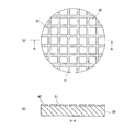
- FIG. (A) is a top view of an example of the polishing pad used by the polishing method using the polishing composition which concerns on embodiment of this invention
- (b) is A of the polishing pad shown to (a) of FIG.
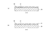
- FIG. (A) is sectional drawing of the 1st modification of the polishing pad shown to (a) of FIG.
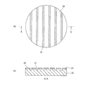
- (b) is sectional drawing of the 2nd modification of the polishing pad shown to (a) of FIG. (A) is a top view of the 3rd modification of the polishing pad shown to (a) of FIG. 3
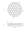
- (b) is AA sectional drawing of the polishing pad shown to (a) of FIG. (A) is a top view of the 4th modification of the polishing pad shown to (a) of FIG. 3
- (b) is AA sectional drawing of the polishing pad shown to (a) of FIG.
- FIG. 11 is a top view of the hard layer making up the polishing pad of FIG. 10; It is a top view of the hard layer which shows the modification of the planar shape of a notch.
- FIG. 2 is a cross-sectional view of a polishing pad having linear grooves in a hard layer. It is sectional drawing of a polishing pad which has a water blocking layer. It is a top view of a hard layer in which an annular penetration which penetrates the polishing layer in a thickness direction is formed in a region inside the outer edge of the polishing layer.
- One embodiment of the present invention is a polishing composition
- a polishing composition comprising an abrasive, a first liquid having hydrophobicity, a surfactant, a layered silicate compound, a thickener, and a second liquid having hydrophilicity.
- the polishing composition according to one aspect of the present invention having such a configuration can reduce the scattering of the polishing composition at the time of polishing while maintaining the polishing performance such as a high polishing rate, ie, a large removal amount. .
- the object to be polished according to this embodiment is not particularly limited, but preferably contains at least one selected from the group consisting of an alloy material, a resin material, a material such as a metal, a metalloid or an oxide thereof, and a glass material. Furthermore, it may be a composite material of these materials. In particular, a resin material used for a paint surface such as a body of an automobile is preferable.
- the alloy is a covalent material in which one metal element or more and one nonmetal element such as carbon, nitrogen, silicon, etc. are shared with one metal element, and the mechanical strength is to pure metal. It is manufactured for the purpose of improving the properties such as chemical resistance, corrosion resistance and heat resistance.
- aluminum alloy is lightweight and has excellent strength, and therefore, is used for various applications such as structural materials such as building materials and containers, transportation equipment such as automobiles, ships, and aircrafts, various electric appliances, and electronic components. It is done.
- titanium alloys are widely used for precision instruments, accessories, tools, sports goods, medical parts and the like because they are lightweight and excellent in corrosion resistance.
- stainless steel and nickel alloys which are iron-based alloys have excellent corrosion resistance, they are used in various applications such as tools, machine tools, cookware, as well as structural materials and transport equipment.
- copper alloys are widely used for decorative articles, dishes, parts of musical instruments and electric materials, etc. because of their beautiful finish. ing. Furthermore, in recent years, materials including resins have also been used in the above applications.
- the alloy material contains a metal species which is a main component and a metal species which is different from the main component.
- the alloy materials are named based on the metal species that are the main components.
- Examples of alloy materials include aluminum alloys, iron alloys, titanium alloys, nickel alloys, and copper alloys. These alloy materials may be used alone or in combination of two or more. Among them, it is preferable to include at least one selected from the group consisting of an aluminum alloy and an iron alloy. In addition, it is preferable to use an alloy material in which the Vickers hardness (HV) of the metal species as the main component and the metal species different from the main component differ by 5 or more.
- HV Vickers hardness
- the aluminum alloy contains aluminum as a main component, and preferably contains at least one selected from the group consisting of magnesium, silicon, copper, zinc, manganese, chromium, and iron as metal species different from the main component.
- the lower limit of the content of the metal species different from the above main component in the aluminum alloy is not particularly limited, but is preferably 0.1 mass% or more with respect to the entire aluminum alloy.
- the upper limit of the content of the metal species different from the above main component in the aluminum alloy is not particularly limited, but is preferably 10% by mass or less with respect to the entire aluminum alloy.
- the aluminum alloy examples include, for example, Al-Cu-based, Al-Cu-Mg-based alloy No. 2000, Al-Mn-based alloy No. 3000, Al as described in JIS H4000: 2006. Alloy number 4000 of Si-Si, alloy number 5000 of Al-Mg, Alloy number 6000 of Al-Mg-Si, alloy number Al-Zn-Mg of 7000, Al-Fe-Mn Alloy number 8000 series etc. are mentioned.
- the iron alloy contains iron as a main component, and preferably contains at least one selected from the group consisting of chromium, nickel, molybdenum, and manganese as a metal species different from the main component.
- the lower limit of the content of the metal species different from the above main component in the iron alloy is not particularly limited, but is preferably 10% by mass or more with respect to the entire iron alloy.
- the upper limit of the content of the metal species different from the above main component in the iron alloy is not particularly limited, but is preferably 50% by mass or less with respect to the entire iron alloy.
- the iron alloy is preferably stainless steel.
- stainless steel for example, in the symbol of the type described in JIS G4303: 2005, SUS201, SUS303, 303Se, SUS304, SUS304L, SUS304NI, SUS305, SUS305 JI, SUS309S, SUS310S, SUS316, SUS316L, SUS321 SUS347, SUS384, SUSXM7, SUS303F, SUS303C, SUS430, SUS430F, SUS434, SUS410, SUS416, SUS420J1, SUS420J2, SUS420F, SUS420C, SUS631J1 and the like.
- the titanium alloy contains titanium as a main component, and as metal species different from the main component, for example, aluminum, iron, vanadium and the like are contained.
- the content of the metal species different from the main component in the titanium alloy is, for example, 3.5% by mass or more and 30% by mass or less with respect to the entire titanium alloy.
- Examples of titanium alloys include 11 to 23, 50, 60, 61 and 80 of the types described in JIS H4600: 2012.
- the nickel alloy contains nickel as a main component, and as a metal species different from the main component, for example, at least one selected from iron, chromium, molybdenum, and cobalt.
- the content of the metal species different from the main component in the nickel alloy is, for example, 20% by mass or more and 75% by mass or less with respect to the entire nickel alloy.
- a nickel alloy NCF600,601,625,750,800,800H, 825, NW0276,4400,6002,6022 etc. are mentioned, for example in the alloy number described in JIS H4551: 2000.
- the copper alloy contains copper as a main component and as a metal species different from the main component, for example, at least one selected from iron, lead, zinc, and tin.
- the content of the metal species different from the main component in the copper alloy is, for example, 3% by mass or more and 50% by mass or less with respect to the entire copper alloy.
- a copper alloy for example, in the alloy numbers described in JIS H 3100: 2006, C2100, 2200, 2300, 2400, 2600, 2680, 2720, 2801, 3560, 3561, 3710, 3713, 4250, 4430, 4621, 4640 , 6140, 6161, 6280, 6301, 7060, 7150, 1401, 2051, 6711, 6712 and the like.
- the type of the resin material is not particularly limited, and any of a thermosetting resin and a thermoplastic resin may be used.
- a thermosetting resin an epoxy resin, a polyimide resin, a phenol resin, an amino resin, unsaturated polyester resin, a thermosetting polyurethane resin etc. are mentioned, for example.
- thermoplastic resin examples include, for example, polystyrene resin, acrylonitrile-butadiene-styrene copolymer resin (ABS resin), (meth) acrylic resin (methacrylic and / or acrylic resin), organic acid vinyl ester resin or a derivative thereof, Vinyl resins, halogen-containing resins such as polyvinyl chloride, polyvinylidene chloride and polyvinylidene fluoride, olefin resins such as polyethylene and polypropylene, polycarbonate resins, saturated polyester resins such as polyethylene terephthalate and polyethylene naphthalate, polyamide resins, thermoplastic polyurethane resins , Polysulfone resin (polyether sulfone, polysulfone etc.), polyphenylene ether resin (polymer of 2,6-xylenol etc.), cellulose derivative (cellulose ester , Cellulose carbamates, cellulose ethers), silicone resin (polydimethylsilox
- the above resins may be used alone or in combination of two or more.
- thermoplastic resins are preferable from the viewpoint of impact resistance and weather resistance, and polycarbonate resins are more preferable.
- the object to be polished containing a resin material may be, for example, in the form of a member (member made of resin) formed of a resin material, or in the form of a composite material having a resin coating film on the surface of a metal substrate etc. It is also good and not restricted.
- resin used for a coating film a thermosetting polyurethane resin, a (meth) acrylic resin, etc. are mentioned.
- the resin coating may be a clear clear coating.
- the type of coating member (that is, the application of the resin coating film) is not particularly limited, but can be preferably used for a three-dimensional resin material, for example, a car body of a car, a railway car, an aircraft, a resin member It can be mentioned.
- the resin coating film coated on the surface of the car body of the automobile has a large area and a curved surface, but the polishing composition of the present embodiment is suitable for polishing the outer surface of such a resin coating film. .
- Metal and metalloids and their oxides examples include aluminum, iron, zirconium, copper, nickel, gold, silver, bismuth, manganese, zinc and the like.
- the type of metalloid includes, for example, Group IV semiconductors such as silicon (Si) and germanium (Ge), II-VI compound semiconductors such as zinc selenide (ZnSe), cadmium sulfide (CdS) and zinc oxide (ZnO) , Group III-V compound semiconductors such as gallium arsenide (GaAs), indium phosphide (InP), and gallium nitride (GaN), Group IV compound semiconductors such as silicon carbide (SiC) and silicon germanium (SiGe), copper indium indium There may be mentioned chalcopyrite semiconductors such as selenium (CuInSe 2 ) and the like. Moreover, it can use suitably also to the oxide of these materials.
- Glass material examples include blue plate glass, quartz glass, tempered glass, crystallized glass, aluminosilicate glass, glassy carbon and the like.
- the polishing composition of the present embodiment contains an abrasive.
- Abrasive grains have the function of mechanically polishing an object to be polished.
- Specific examples of the abrasive used in the present embodiment include, for example, aluminum oxide (alumina), silicon oxide (silica), cerium oxide (ceria), zirconium oxide, titanium oxide (titania), tin oxide, manganese oxide Etc., metal carbides such as silicon carbide and titanium carbide, metal nitrides such as silicon nitride and titanium nitride, metal borides such as titanium boride and tungsten boride, silicate compounds such as zircon, diamond, etc. Can be mentioned.
- the abrasive grains may be used alone or in combination of two or more. Moreover, a commercial item may be used for this abrasive grain, and a synthetic product may be used.
- abrasives at least one selected from the group consisting of metal oxides and metal carbides is preferable, from the viewpoint that abrasives having various particle diameters can be easily obtained and an excellent polishing rate can be obtained, and carbonized Silicon, silicon dioxide or metal oxides are more preferred, and at least one of aluminum oxide, cerium oxide and zirconium oxide is more preferred. Also, a mixture of alumina and zircon can be preferably used.
- the lower limit of the volume average particle diameter (average secondary particle diameter) of the abrasive grains may be 0.05 ⁇ m or more, preferably 0.1 ⁇ m or more, and more preferably 0.3 ⁇ m or more.
- the upper limit of the volume average particle diameter (average secondary particle diameter) of the abrasive grains may be 50.0 ⁇ m or less, preferably 40.0 ⁇ m or less, and more preferably 15.0 ⁇ m or less. More preferably, it is 8.0 ⁇ m or less.
- the volume average particle diameter of the abrasive grains decreases, it becomes easy to obtain a surface with low defects and small roughness. From the above, the volume average particle diameter of the abrasive grains is more preferably 0.2 ⁇ m or more and 15.0 ⁇ m or less, and particularly preferably 0.3 ⁇ m or more and 8.0 ⁇ m or less.
- the volume average particle diameter of the abrasive grains is defined as an integrated 50% particle diameter (D 50 ) based on the volume-based particle size distribution.
- D 50 of the abrasive grains can be measured by using a commercially available particle size measuring device.
- a particle size measuring apparatus may be based on any technique such as a dynamic light scattering method, a laser diffraction method, a laser scattering method, or a pore electrical resistance method.
- a measuring method and apparatus for D 50 include measuring method and apparatus of example.
- the lower limit of the content of abrasive grains in the polishing composition is preferably 0.1% by mass or more, more preferably 5% by mass or more, and still more preferably 10% by mass or more. As the abrasive content increases, the polishing rate increases. Moreover, it is preferable that it is 50 mass% or less, and, as for the upper limit of content of the abrasive grain in polishing composition, it is more preferable that it is 35 mass% or less. As the content of abrasive grains decreases, in addition to the reduction of the manufacturing cost of the polishing composition, it becomes easy to obtain a surface with few defects such as scratches by polishing using the polishing composition.
- the polishing composition according to the present embodiment includes a hydrophobic first liquid that can be a dispersoid or a dispersion medium.
- the first liquid is not particularly limited as long as it is a solvent having hydrophobicity, but petroleum solvents such as petroleum ether, petroleum naphtha, hydrogenated petroleum naphtha, solvent naphtha are preferable, and saturated hydrocarbons and non-hydrophobic solvents are preferable.
- a solvent containing at least one of saturated hydrocarbons is more preferable, a paraffin-type, iso-paraffin-type, naphthene-type and terpene-type solvent is more preferable, and a solvent containing iso-paraffin-type hydrocarbon is particularly preferable.
- the polishing composition according to the present embodiment includes a surfactant for dispersing or emulsifying a first liquid having hydrophobicity or a second liquid having hydrophilicity described later.
- a surfactant for dispersing or emulsifying a first liquid having hydrophobicity or a second liquid having hydrophilicity described later.
- the surfactant improves the cleaning efficiency of the surface to be polished after polishing by imparting hydrophilicity to the surface to be polished after polishing, it is possible to prevent the adhesion of dirt to the surface to be polished and the like.
- the type of surfactant is not particularly limited, and it may be any of anionic surfactant, cationic surfactant, amphoteric surfactant and nonionic surfactant. These surfactants may be used alone or in combination of two or more.
- anionic surfactants include polyoxyethylene alkyl ether acetic acid, polyoxyethylene alkyl sulfuric acid ester, alkyl sulfuric acid ester, polyoxyethylene alkyl ether sulfuric acid, alkyl ether sulfuric acid, alkyl benzene sulfonic acid, alkyl phosphoric acid ester, poly Examples thereof include oxyethylene alkyl phosphate, polyoxyethylene sulfosuccinic acid, alkyl sulfosuccinic acid, alkyl naphthalene sulfonic acid, alkyl diphenyl ether disulfonic acid, and salts thereof.
- cationic surfactants include alkyl trimethyl ammonium salts, alkyl dimethyl ammonium salts, alkyl benzyl dimethyl ammonium salts, alkyl amine salts and the like.
- amphoteric surfactants include alkyl betaines, alkyl amine oxides and the like.
- nonionic surfactants include polyoxyethylene alkyl ether, polyoxyalkylene alkyl ether, sorbitan fatty acid ester, glycerin fatty acid ester, polyoxyethylene fatty acid ester, polyoxyethylene alkylamine, alkyl alkanolamide and the like .
- HLB Hydrophilic-Lipophilic Balance
- the content of the surfactant in the polishing composition is preferably 0.01% by mass or more, and more preferably 0.1% by mass or more.
- the content of the surfactant in the polishing composition is preferably 3.0% by mass or less, and more preferably 1.0% by mass or less.
- the polishing composition of the present embodiment contains a layered silicate compound as a dispersant.
- the layered silicate compound can be present in a state where it becomes steric hindrance among the particles of the abrasive grains, so that the effect of improving the dispersibility and redispersion of the abrasive grains is obtained.
- the layered silicate compound basically has a structure in which silicate tetrahedrons are connected in a plane, and includes one or two silicate tetrahedron sheets and one alumina octahedron sheet in a unit structure. It is a structure characterized by In the interlayer (between unit structures), cations such as sodium, potassium and calcium are present. Further, the layered silicate compound is a substance having a property that the crystal is peeled off thinly.
- the layered silicate compound used in the present embodiment may be a natural product, a synthetic product, a commercially available product, or a mixture thereof.
- Examples of the synthesis method of the layered silicate compound include, but are not limited to, a hydrothermal synthesis reaction method, a solid phase reaction method, a melt synthesis method and the like.
- the layered silicate compound examples include talc, pyrophyllite, smectite (saponite, hectorite, sauconite, stevensite, bentonite, montmorillonite, beidellite, nontronite, etc.), vermiculite, mica (gold) Mica, biotite, chinwaldo mica, muscovite, paragonite, ceradonite, etc., chlorite (crinochlore, chamosite, nimite, peninite, sudoite, donbasite, etc.), brittle mica (clintite, margarite, etc.) And sourite, serpentine (antigorite, lizardite, chrysotile, amesite, clonsteadite, vercherin, grinalite, garnierite, etc.), kaolin (kaolinite, dickite, nacrite, halloysite, etc.), etc. .
- layered silicate compounds may be used alone or in combination of two or more.
- bentonite sodium bentonite
- the interlayer ion is sodium ion
- steven site sodium steven site
- easier improvement of the dispersibility and redispersibility of the abrasive grains Hectorite (sodium hectorite) and mica (sodium tetrasilicon mica) are preferred.
- the lower limit of the average primary particle diameter of the layered silicate compound may be 0.01 ⁇ m or more, and preferably 0.03 ⁇ m or more.
- the upper limit of the average primary particle diameter of the layered silicate compound may be 15.0 ⁇ m or less, preferably 12.0 ⁇ m or less, and more preferably 10.0 ⁇ m or less, 5.0 ⁇ m or less Is more preferably 3.0 ⁇ m or less, still more preferably 1.0 ⁇ m or less, still more preferably 0.8 ⁇ m or less, still more preferably 0.5 ⁇ m or less And particularly preferably 0.3 ⁇ m or less.
- the average primary particle diameter of the layered silicate compound is more preferably 0.01 ⁇ m or more and 15.0 ⁇ m or less, more preferably 0.03 ⁇ m or more and 3.0 ⁇ m or less, and 0.03 ⁇ m or more and 0.8 ⁇ m or less Is more preferable, and particularly preferably 0.03 ⁇ m or more and 0.3 ⁇ m or less.
- the average primary particle size of the layered silicate compound can be measured, for example, using a scanning electron microscope (SEM).
- the lower limit of the content of the layered silicate compound in the polishing composition is preferably 0.001% by mass or more, and more preferably 0.05% by mass or more.
- the upper limit of the content of the layered silicate compound in the polishing composition is preferably 10% by mass or less, more preferably 5% by mass or less, and more preferably 2% by mass or less. It is more preferably 1% by mass or less, more preferably 0.8% by mass or less, still more preferably 0.5% by mass or less, particularly preferably 0.3% by mass or less preferable. If it is such a range, the effect of the said this embodiment is efficiently acquired.
- the polishing composition according to this embodiment includes a hydrophilic second liquid that can be a dispersoid or a dispersion medium.
- the second liquid is not particularly limited as long as it is a solvent having hydrophilicity, but water is typically preferable. From the viewpoint of suppressing inhibition of the action of other components, water which does not contain impurities as much as possible is preferable. Specifically, after removing impurity ions with an ion exchange resin, it is pure after removing foreign substances through a filter. Water, ultrapure water, or distilled water is preferred.
- the volume ratio (L1 / L2) of the first liquid (L1) having hydrophobicity to the second liquid (L2) having hydrophilicity is appropriately changed.
- the volume ratio may be less than 1, may be 0.7 or less, 0.5 or less, 0.3 or less, or 0.1 or less.
- the volume ratio may be 1 or more, 1.5 or more, 2 or more, 3 or more, 5 or more, or 10 or more.
- the emulsion type of the polishing composition may be an oil-in-water (O / W) emulsion, or a water-in-oil (W / O) emulsion.
- the polishing composition tends to be an oil-in-water (O / W) emulsion.
- the volume ratio (L1 / L2) is large (for example, 1 or more), the polishing composition tends to form a water-in-oil (W / O) type emulsion.
- thickeners examples include polyacrylic acid, sodium polyacrylate (for example, completely neutralized product, partially neutralized product, alkali-soluble polyacrylic acid of association type (acrylic polymer), etc., acrylic compound, urethane Synthetic thickeners such as sodium compounds, cellulose thickeners (semi-synthetic thickeners) such as carboxymethyl cellulose and carboxyethyl cellulose, natural thickeners such as agar, carrageenan, layered silicate compounds, xanthan gum and gum arabic A viscosity etc. are mentioned.
- polyacrylic acid and an alkali are used in combination.
- alkali examples include inorganic alkalis such as sodium hydroxide, potassium hydroxide and ammonia, and organic alkalis such as triethanolamine.
- inorganic alkalis such as sodium hydroxide, potassium hydroxide and ammonia
- organic alkalis such as triethanolamine.
- polyacrylic acid exhibits a thickening effect.
- the thickener may be a Newtonian fluid or a non-Newtonian fluid.
- the polishing composition according to the present embodiment preferably contains an additive.
- the additive include, for example, an oil, an emulsion stabilizer, and a polymer material.
- the additives may be used alone or in combination of two or more.
- the addition of the additive improves the stability of the emulsion.
- oil examples include liquid paraffin, polybutene, ⁇ -olefin oligomer, alkylbenzene, polyol ester, phosphoric acid ester, synthetic oil such as silicone oil, spindle oil, neutral oil, mineral oil such as bright stock, castor oil, soybean oil
- vegetable oils and fats such as coconut oil, linseed oil, cottonseed oil, rapeseed oil, tung oil, olive oil and the like, animal fats and oils such as beef tallow, squalane and lanolin.
- the emulsion stabilizer examples include glycerin, polyhydric alcohols such as ethylene glycol and propylene glycol, and aliphatic alcohols such as cetyl alcohol and stearyl alcohol.
- the content of the additive in the polishing composition is preferably 0.1% by mass or more, and more preferably 1.0% by mass or more.
- the content of the additive in the polishing composition is preferably 12.0% by mass or less, and more preferably 8.0% by mass or less. When the content of the additive is in the above range, the stability of the emulsion in the polishing composition is increased.
- the polishing composition of the present embodiment is not particularly limited, but the pH can be adjusted by the addition of an acid or a salt thereof described below, or a base or a salt thereof.
- the polishing composition of the present embodiment preferably contains an acid or a salt thereof.
- the acid or a salt thereof serves to adjust the pH of the polishing composition.
- any of inorganic acids and organic acids can be used.
- the inorganic acid include, for example, hydrochloric acid, sulfuric acid, nitric acid, hydrofluoric acid, boric acid, carbonic acid, hypophosphorous acid, phosphorous acid, phosphoric acid and the like.
- organic acid for example, formic acid, acetic acid, propionic acid, butyric acid, valeric acid, 2-methylbutyric acid, n-hexanoic acid, 3,3-dimethylbutyric acid, 2-ethylbutyric acid, 4-methylpentanoic acid, n -Heptanoic acid, 2-methylhexanoic acid, n-octanoic acid, 2-ethylhexanoic acid, benzoic acid, glycolic acid, salicylic acid, glyceric acid, oxalic acid, malonic acid, succinic acid, glutaric acid, adipic acid, pimelic acid, Maleic acid, phthalic acid, malic acid, tartaric acid, citric acid, lactic acid, diglycolic acid, 2-furancarboxylic acid, 2,5-furancarboxylic acid, 3-furancarboxylic acid, 2-tetrahydrofuranic acid, methoxyacetic acid
- salts Group 1 element salts, Group 2 element salts, aluminum salts, ammonium salts, amine salts, quaternary ammonium salts and the like can be mentioned. These acids or their salts may be used alone or in combination of two or more. Among these, nitric acid and citric acid are preferable.
- a base or a salt thereof may be used to adjust the pH.
- the base or a salt thereof include amines such as aliphatic amines and aromatic amines, organic bases such as quaternary ammonium hydroxide, hydroxides of alkali metals such as sodium hydroxide and potassium hydroxide, magnesium hydroxide, Examples thereof include hydroxides of Group 2 elements such as calcium hydroxide, and ammonia.
- the polishing composition of the present embodiment suppresses the corrosion of the oxidizing agent that oxidizes the surface of the object to be polished, the water-soluble polymer acting on the surface of the object to be polished and the surface of the abrasive grain, and the object to be polished, if necessary.
- the composition may further contain other components such as anticorrosion agents and chelating agents, preservatives having other functions, fungicides, polymer materials and the like.
- the oxidizing agent include hydrogen peroxide, peracetic acid, percarbonate, urea peroxide, perchlorate, persulfate and the like.
- water-soluble polymers examples include polycarboxylic acids such as polyacrylic acid, polysulfonic acids, polysulfonic acids such as polystyrene sulfonic acid, xanthan gum, polysaccharides such as sodium alginate, cellulose derivatives such as hydroxyethyl cellulose and carboxymethyl cellulose, polyethylene glycol Polyvinyl alcohol, polyvinyl pyrrolidone, alkylol ammonium salt, polyoxyethylene alkyl ether, polyoxyethylene alkyl phenyl ether, sorbitan monooleate, oxyalkylene polymer having one or more oxyalkylene units, and the like. .
- salts of the above compounds can also be suitably used as the water-soluble polymer.
- anticorrosive agent examples include amines, pyridines, tetraphenylphosphonium salts, benzotriazoles, triazoles, tetrazoles, benzoic acid and the like.
- chelating agents include carboxylic acid type chelating agents such as gluconic acid, amine type chelating agents such as ethylenediamine, diethylenetriamine and trimethyltetraamine, ethylenediaminetetraacetic acid, nitrilotriacetic acid, hydroxyethylethylenediaminetriacetic acid, triethylenetetramine hexaacetic acid
- Polyaminopolycarboxylic chelating agents such as diethylenetriaminepentaacetic acid, 2-aminoethylphosphonic acid, 1-hydroxyethylidene-1,1-diphosphonic acid, aminotri (methylenephosphonic acid), ethylenediaminetetrakis (methylenephosphonic acid), diethylenetriaminepenta ( Methylene phospho
- preservatives include sodium hypochlorite and the like.
- fungicides include oxazolines such as oxazolidine-2,5-dione.
- alkylol ammonium salt of the copolymer which has an acidic radical, etc. are mentioned.
- the method for producing the polishing composition of the present embodiment is not particularly limited.
- a surfactant is dissolved in a second liquid having hydrophilicity, and the first liquid having hydrophobicity is stirred and mixed therein. Do.
- the polishing composition of the present embodiment can be obtained by stirring and mixing the layered silicate compound, the abrasive grains, the thickener, and other components as needed.
- the temperature at which each component is mixed is not particularly limited, but 10 ° C. or more and 40 ° C. or less is preferable, but by heating, the second liquid and the surfactant are stirred and mixed in the first liquid to perform phase inversion emulsification May be Also, the mixing time is not particularly limited.
- the polishing composition of the present embodiment is suitably used for polishing an alloy material, a resin material, a metal, a metalloid or a metalloid thereof, an oxide thereof, an object to be polished including a glass material, and a composite material of these materials. Used.
- the polishing composition of the present embodiment is suitable for polishing an object to be polished (for example, a painted surface of a vehicle such as an automobile) having a curved surface to be polished.
- a method of polishing a resin-coated surface will be described.
- the configuration of the polishing apparatus that performs polishing is not particularly limited, and general polishing apparatuses such as single-sided polishing machines, double-sided polishing machines, and lens polishing machines can be used.
- general polishing apparatuses such as single-sided polishing machines, double-sided polishing machines, and lens polishing machines can be used.
- the automatic polishing apparatus shown in FIG. It can be used.
- the automatic polishing apparatus of FIG. 1 includes a robot arm 102, a polishing pad 10, a polishing tool 104, a pressing force detection unit 105, and a controller 107. Since the robot arm 102 has a plurality of joints 120, 121, 122, the tip portion 123 to which the polishing pad 10, the polishing tool 104, and the pressing force detection unit 105 are attached can be moved in a plurality of directions. .
- the coated member, which is the object to be polished 90 is one in which the surface of the substrate is coated with a resin coating film, and the resin coated surface, which is the polished surface 90a of this coated member, has a large area and a curved surface. .
- the polishing tool 104 is attached to the tip end portion 123 via the pressing force detection unit 105, and rotates the polishing pad 10 with a direction perpendicular to the polishing surface 30 of the polishing pad 10 as a rotation axis by a built-in drive means.
- the driving means of the polishing tool 104 is not particularly limited, but in general, single action, double action, gear action and the like are used, and double action is preferred for polishing a painted member.
- the controller 107 controls the behavior of the robot arm 102 and the rotation of the polishing pad 10 by the polishing tool 104.
- the polishing composition is supplied between the polishing surface 30 of the polishing pad 10 and the resin-coated surface of the coating member from the polishing composition supply mechanism (not shown).
- the controller 107 presses the polishing surface 30 of the polishing pad 10 against the resin-coated surface of the coating member by the robot arm 102 and rotates the polishing pad 10 to polish the resin-coated surface of the coating member.
- the pressing force detection unit 105 detects the pressing force of the polishing surface 30 of the polishing pad 10 against the resin-coated surface of the coating member.
- the controller 107 may adjust the force for pressing the polishing surface 30 against the resin-coated surface of the coating member based on the detection result of the pressing force by the pressing force detection unit 105.
- the controller 107 controls the polishing pad 10 on the resin coated surface of the coating member while keeping the pressing force of the polishing surface 30 against the resin coated surface of the coating member constant based on the detection result of the pressing force by the pressing force detection unit 105.
- the robot arm 102 may be controlled to move the robot arm 102.
- the method of fixing the polishing pad 10 to the pad attachment part of the polishing tool 104 is not particularly limited, for example, a fixing method using a double-sided adhesive tape, an adhesive, a surface fastener or the like can be mentioned.
- polishing tool 104 among the polishing pads 10 is not specifically limited, For example, linear shape, curvilinear shape, the shape that combined these, etc. are mentioned.
- the outer peripheral shape of the portion of the polishing pad 10 in contact with the pad attachment portion of the polishing tool 104 is not particularly limited, and examples thereof include a circular shape, a polygonal shape, a petal shape, and a star shape.
- the surface of the portion of the polishing pad 10 in contact with the pad attachment portion of the polishing tool 104 may be subjected to processing such as groove processing, hole processing, embossing processing or the like, but may be subjected to processing other than these. The details such as the configuration and the shape of the polishing pad 10 will be described later.
- the material of the pad attachment portion of the polishing tool 104 is not particularly limited, but for example, resin, metal, ceramic, fiber reinforced resin, composite material, etc. can be used.
- resin resin, metal, ceramic, fiber reinforced resin, composite material, etc.
- fiber reinforced resin carbon fiber reinforced resin and glass fiber reinforced resin are mentioned, for example.
- the kind of resin used for fiber reinforced resin is not specifically limited, For example, an epoxy resin is mentioned.
- the composite material etc. which combined 2 or more types of materials, such as a metal which contained the inorganic particle intentionally, for example, are mentioned.
- the polishing method of the present embodiment is not limited to the above-described automatic polishing apparatus.
- the polishing method of the present embodiment may be applied to the case where a polishing pad is attached to the tip of a hand polisher and a polishing operator manually moves the hand polisher to polish a resin-coated surface.
- the driving means of the hand polisher is not particularly limited, but in general, single action, double action, gear action and the like are used, and double action is preferred for polishing a painted member.
- the polishing can be performed using an apparatus and conditions used for normal metal polishing.
- a general polishing apparatus there is a single-side polishing apparatus or a double-side polishing apparatus.
- an object to be polished (preferably a substrate-like object to be polished) is held and polished using a holder called a carrier.
- One side of the object to be polished is polished by pressing the surface plate with the polishing cloth attached to one side of the object to be polished while rotating the surface plate while supplying the composition for polishing.
- a holder called a carrier is used to hold an object to be polished, and while supplying a polishing composition from above, a platen having an abrasive cloth attached to the opposite surface of the object to be polished is pressed. Both sides of the object to be polished are polished by rotating in the relative direction. At this time, the polishing pad and the polishing composition, the physical action by the friction with the object to be polished, and the chemical action of the polishing composition on the object to be polished, it is polished.
- a polishing load can be mentioned.
- the lower limit of the polishing load in the polishing method according to the present embodiment is not particularly limited, but is preferably 20 g / cm 2 or more, and more preferably 50 g / cm 2 or more.
- the upper limit of the polishing load is preferably 1000 g / cm 2 or less, more preferably 500 g / cm 2 or less. As the polishing load decreases, surface roughness of the polishing surface is suppressed.
- a linear velocity (polishing linear velocity) in polishing can be mentioned.
- the rotational speed of the polishing pad, the rotational speed of the carrier, the size of the object to be polished, the size of the object to be polished, etc. affect the linear velocity, but if the linear velocity is large, the frictional force applied to the object to be polished becomes large.
- the object is likely to be mechanically polished.
- friction heat may be generated by the friction, and the chemical action of the polishing composition may be increased.
- the lower limit of the linear velocity of polishing in the polishing method according to the present embodiment is not particularly limited, but is preferably 10 m / min or more, and more preferably 20 m / min or more.
- the upper limit of the polishing linear velocity is preferably 300 m / min or less, more preferably 150 m / min or less. Within this range, in addition to obtaining a sufficiently high polishing rate, an appropriate frictional force can be applied to the object to be polished. That is, in the present embodiment, the polishing linear velocity is preferably 10 m / min to 300 m / min, and more preferably 20 m / min to 150 m / min.
- the polishing composition of the present embodiment may be used as a step completed in a single step, or may be used in one or more steps in a step having a plurality of steps of polishing. For example, when it is used in a process having three steps of polishing, it can be used in any one or more of the first step of rough polishing, the second step of middle polishing, and the third step of finish polishing.
- the polishing composition once used for polishing can be recovered and used for polishing again.
- the method of reusing the polishing composition there is a method of recovering the polishing composition discharged from the polishing apparatus into a tank and circulating it again into the polishing apparatus for use. Circulating use of the polishing composition reduces the environmental load by reducing the amount of the polishing composition discharged as waste liquid, and reduces the amount of the polishing composition to be used. It is useful in the point which can suppress the manufacturing cost concerning grinding
- the polishing composition of the present embodiment When the polishing composition of the present embodiment is used in circulation, some or all of the abrasive grains, layered silicate compound, and other additives consumed or lost by polishing are recycled as a composition modifier. It can be added into. In this case, some or all of the abrasive grains, the layered silicate compound, and other additives may be mixed at an arbitrary mixing ratio as the composition modifier. By additionally adding a composition modifier, the polishing composition is adjusted to a composition suitable for reuse, and the polishing is suitably maintained.
- the concentrations of the abrasive grains, the layered silicate compound, and the other additives contained in the composition modifier are arbitrary and not particularly limited, but may be appropriately adjusted according to the size of the circulation tank and the polishing conditions. preferable.
- the polishing composition of the present embodiment may be a one-component type, or may be a multi-component type including a two-component type.
- the polishing composition of the present embodiment may be prepared, for example, by diluting the stock solution of the polishing composition with a dilution liquid such as water or oil, for example, 10 times or more.
- the polishing pad 10 used in the polishing method using the polishing composition of the present embodiment may be formed of, for example, a polyurethane type, a polyurethane foam type, a non-woven type, a suede type, or the like.
- the details of the polishing pad 10 used in the polishing method using the polishing composition of the present embodiment will be described.
- the configuration of the polishing pad 10 is not particularly limited as long as it has a polishing surface.
- the polishing pad 10 may have a structure that causes the polishing surface of the polishing pad 10 to follow the resin-coated surface.
- the structure for causing the polishing surface of the polishing pad 10 to follow the resin-coated surface has, for example, a two-layer structure including a hard layer forming the polishing surface and a soft layer supporting the hard layer. And may have a multilayer structure of two or more layers.
- the polishing pad 10 As an example of the polishing pad 10, a configuration example of the polishing pad 10 having a two-layer structure including a hard layer forming a polishing surface and a soft layer supporting the hard layer will be described.
- the hard layer forming the polishing surface is simply referred to as "hard layer”
- the soft layer supporting the hard layer is simply referred to as "soft layer”.
- the “hard layer” and the “soft layer” represent relative layer properties. That is, the above-mentioned hard means that the hardness of "the layer which forms the polished surface" which is one layer is higher than the hardness of the "the layer which supports the layer which has the polished surface" which is the other layer. It is.
- the softness means that the hardness of the other layer "the layer supporting the layer having the polishing surface” is lower than the hardness of the one layer "the layer forming the polishing surface”. Is meant.
- the polishing pad 10 may have a two-layer structure including a hard layer 40 and a soft layer 50.
- the hard layer 40 may have the polishing surface 30 of the polishing pad 10.
- the soft layer 50 supports the hard layer 40, and is distorted according to the curved surface when the polishing surface 30 is pressed against the curved surface of the resin-coated surface. Therefore, the hard layer 40 tends to bend along the curved surface, and the polishing surface 30 tends to follow the curved surface of the resin-coated surface.
- the hardness of the hard layer 40 is preferably 60 or more, and more preferably 80 or more, in terms of A hardness measured by the method defined in JIS K 6253.
- the A hardness of the hard layer 40 is preferably 99 or less.
- the A hardness of the hard layer 40 is preferably 60 or more and 99 or less, and more preferably 80 or more and 99 or less. Within such a range, it becomes difficult to abrade the curved surface of the resin-coated surface by the polishing pad 10, and it becomes possible to remove the waviness of the surface of the resin-coated surface.
- regulated to JISK6253 is 100.
- the A hardness of the hard layer 40 can be measured in accordance with JIS K 6253, for example, by attaching an ASKER rubber hardness tester A type to a constant pressure loader CL-150L.
- the material of the hard layer 40 is not particularly limited, and may be, for example, a non-woven fabric or a sheet containing resin fibers.
- the non-woven fabric pad may be configured by impregnating only fibers or fibers with resin.
- the material of the hard layer 40 may be a material containing a synthetic resin.
- the synthetic resin contained in the hard layer 40 may be made of, for example, a material containing at least one of nylon resin, polyester resin, polyurethane resin, epoxy resin, aramid resin, polyimide resin, or polyethylene resin. If it is the above-mentioned material, a deep crack (scratch) can be reduced to a field to be polished.
- Specific examples of the resin fiber of the hard layer 40 are preferably nylon resin, polyester resin, polyurethane resin, and polyethylene resin, and more preferably nylon resin and polyester resin.
- hardening of the synthetic resin of the hard layer 40 may be performed by a curing agent or may be performed by heat.
- the hard layer 40 may be made of a fiber material having a fiber density value of 0.08 g / cm 3 or more, and it may be made of a fiber material having a fiber density value of 0.09 g / cm 3 or more preferable.
- the term "fiber density” refers to a value calculated by dividing the basis weight of the fiber material defined by grams per square meter by 10000 and further dividing it by the thickness defined by centimeters.
- the hard layer 40 may be made of a fiber material having a fiber density value of 0.20 g / cm 3 or less, and is made of a fiber material having a fiber density value of 0.12 g / cm 3 or less Is preferable.
- the hard layer 40 may be made of a fiber material having a fiber density value of 0.08 g / cm 3 or more and 0.20 g / cm 3 or less, and the fiber density value of 0.09 g preferred if configured by the fiber material is / cm 3 or more 0.12 g / cm 3 within the following range.
- an abrasive comprising an emulsion comprising an abrasive, a first liquid having hydrophobicity, a surfactant, a layered silicate compound, and a second liquid having hydrophilicity.
- a polishing composition comprising an emulsion further comprising at least one of an oil agent, an emulsion stabilizer, and a thickener as an additive to the composition or the polishing composition thereof is sufficiently improved. It is possible to obtain a polishing rate. If the fiber density value is less than 0.08 g / cm 3 , the durability of the hard layer 40 tends to decrease. When the fiber density value exceeds 0.20 g / cm 3 , the polishing rate tends to decrease.
- the hard layer 40 has a sparse / dense structure and is made of a sheet material having a ratio of sparse portions of the polishing surface 30 (hereinafter, also referred to as area ratio of sparse portions) of 52% to 96%. It is preferable if it is composed of a sheet material having an area ratio of the sparse part of 54% to 96%, and more preferably if it is composed of a sheet material that is 60% to 96%. Within such a range, retention to the polishing interface of a polishing composition comprising an emulsion containing abrasive grains and at least one additive selected from an oil, an emulsion stabilizer, and a thickener, which will be described later.
- the polishing interface of the polishing composition comprising an emulsion containing abrasive grains and at least one additive selected from an oil, an emulsion stabilizer, and a thickener is used. And the polishing rate tends to decrease.
- the area ratio of the sparse portion of the polishing contact surface without the groove may be 52% or more and 96% or less.
- the adjustment method of the area ratio of a sparse part is not specifically limited, For example, in the case of a nonwoven fabric sheet, even if it adjusts by the thickness of a fiber, content of fiber, the quantity of resin impregnated, patterning of the surface etc.
- a mesh structure having a structure in which elongated materials are arranged side by side well it may be adjusted according to the diameter of the structure material, the interval of the structure, the lamination conditions, etc.
- a foam structure it may be adjusted by the kind, amount, etc. of a foaming agent, and in the case of a suede formed by a wet film forming method, it may be adjusted by film forming conditions and buffing conditions.
- the area ratio of the sparse portion of the hard layer 40 can be determined, for example, by image analysis of the surface of the polishing pad measured with a microscope. Specifically, using a VK-X200 manufactured by Keyence Corporation, the surface of the polishing pad has a viewing angle of 1.4 mm ⁇ 1.4 mm and a height direction of 0.1 mm at a magnification of 200 times (10 ⁇ objective, eyepiece) Measure any 10 points at 20x), and use the WinROOF 2018 manufactured by Mitani Corporation to monochrome the obtained image, and blank the entire area of the binarized image automatically It can obtain by calculating the ratio of the area of That is, the above-mentioned "sparse part" is a part in which the fiber etc.
- the ratio of the area of the void in the range of 0.1 mm in thickness from the outermost surface may be 52% or more and 96% or less.
- area refers to the area when the layer having the polishing surface 30 is viewed in the thickness direction.
- the thickness of the resin fiber of the hard layer 40 is not particularly limited, but is preferably 1 denier or more, and 10 denier or less. Further, the type of thickness of the resin fiber may be one type, or two or more types of resin fibers having different types of thickness may be mixed.
- the thickness of the hard layer 40 is not particularly limited, but is preferably 0.05 cm or more. Moreover, it is preferable if it is 0.5 cm or less.
- the hard layer 40 easily bends along the curved surface of the resin-coated surface when the polishing surface 30 is pressed against the curved surface of the resin-coated surface, and polishing is performed There is a tendency for the followability of the polishing surface 30 to the curved surface of the object to be improved. For this reason, the waviness component of the surface shape of the object to be polished can be removed, and the contact area between the polishing surface 30 and the curved surface tends to increase and the polishing efficiency tends to be improved.
- the soft layer 50 is a layer provided to support the hard layer 40 on the surface of the hard layer 40 opposite to the polishing surface 30, and may be a layer made of an elastic material. .
- the elastic body constituting the soft layer 50 may be made of resin, for example.
- the hardness of the soft layer 50 is preferably less than 60 in terms of A hardness measured by the method defined in JIS K 6253, and more preferably 30 or less. That is, it is preferable that the A hardness of the soft layer 50 be lower than the A hardness of the hard layer 40. Within such a range, the soft layer 50 is likely to be distorted when the polishing surface 30 is pressed against the curved surface of the resin-coated surface.
- the A hardness of the soft layer 50 can be measured in accordance with JIS K 6253, for example, by attaching an ASKER rubber hardness tester A type to a constant pressure loader CL-150L.
- the thickness of the soft layer 50 is not particularly limited, but is preferably 0.50 cm or more. Moreover, if the thickness of the soft layer 50 is 5.0 cm or less, it is preferable. With such a range, when the polished surface 30 is pressed against the curved surface of the resin-coated surface, the amount of distortion of the soft layer 50 and the amount of deflection of the hard layer 40 can be secured.
- the material of the soft layer 50 is not particularly limited as long as it has the above-mentioned hardness.
- the material of the soft layer 50 may be, for example, a resin foam such as polyurethane foam or polyethylene foam.
- FIG. 2 illustrates the polishing pad 10 in which the polishing surface 30 is flat
- the present invention is not limited to this.
- the polishing pad 10 may have a groove on the polishing surface 30.
- channel in the polishing surface 30 is demonstrated.
- a first groove 31 and a second groove 32 are formed on the polishing surface 30 of the polishing pad 10.
- the first groove 31 extends along a first direction on the polishing surface 30, and the second groove 32 extends along a second direction on the polishing surface 30 orthogonal to the first direction.
- the grooves are formed in a lattice shape in the polishing surface 30.
- channel is not specifically limited, For example, after forming the 2 layer structure containing the hard layer 40 and the soft layer 50, the layer of the part used as a groove by an etching etc. It may be formed by removing Alternatively, after forming the two-layer structure, it may be formed by scanning the surface while pressing a circular cutting blade rotating at high speed against a predetermined amount of the pad.
- the depths of the first groove 31 and the second groove 32 are not particularly limited, but may be the same as the thickness of the hard layer 40. That is, the hard layer 40 may be divided into a plurality of parts by the first groove 31 and the second groove 32. Also, the first groove 31 and the second groove 32 are formed only in the hard layer 40 and not formed in the soft layer 50. Since the hard layer 40 is divided by the first groove 31 and the second groove 32, when the polishing surface 30 is pressed against the curved surface of the resin-coated surface, the hard layer 40 abuts according to the curved surface It becomes possible to displace in the direction. For this reason, the polished surface 30 can easily follow the curved surface of the resin-coated surface.
- the groove widths of the first groove 31 and the second groove 32 are not particularly limited, but are preferably 0.5 mm or more, for example.
- the groove widths of the first groove 31 and the second groove 32 are not particularly limited, but are preferably 5.0 mm or less, for example. Within such a range, the reduction of the contact area between the polished surface 30 and the resin-coated surface due to the formation of the groove is suppressed, and the hard layer 40 in the case where the polished surface 30 is pressed against the curved surface of the resin-coated surface The displacement amount can be secured to make the polishing surface 30 easy to bend.
- the pitch of the first grooves 31 and the pitch of the second grooves 32 are not particularly limited, but are preferably 5.0 mm or more, for example.
- the pitch of the first grooves 31 and the pitch of the second grooves 32 are not particularly limited, but preferably 50 mm or less, for example.
- “pitch” refers to the distance between the first groove 31 and the second groove 32. Within such a range, the entire polished surface 30 when the polished surface 30 is pressed against the curved surface of the resin-coated surface while suppressing a decrease in the contact area between the polished surface 30 and the resin-coated surface due to the formation of grooves. It is possible to secure the amount of deflection of
- the dimensions of the groove width and the pitch described above are the same as in the first to seventh modifications described below.
- the depths of the first groove 31 and the second groove 32 are not particularly limited, but may be shallower than the thickness of the hard layer 40. That is, the hard layer 40 is not divided into a plurality by the first groove 31 and the second groove 32, and the thickness of the hard layer 40 in the portion of the first groove 31 and the second groove 32 is the thickness of the other portion Thinner than Since the rigidity of the portions of the first groove 31 and the second groove 32 is reduced, the hard layer 40 is easily bent. For this reason, the polished surface 30 can easily follow the curved surface of the resin-coated surface.
- the depths of the first groove 31 and the second groove 32 are not particularly limited, but may be deeper than the thickness of the hard layer 40. That is, the first groove 31 and the second groove 32 may be formed in the hard layer 40 and the soft layer 50. Therefore, the support surface 51 of the soft layer 50 supporting the hard layer 40 may also be divided by the first groove 31 and the second groove 32. The plurality of divided hard layers 40 may be respectively supported by the plurality of divided support surfaces 51. Since the first groove 31 and the second groove 32 are also formed in the soft layer 50, the rigidity of the soft layer 50 is reduced, and the curved surface is obtained when the polishing surface 30 is pressed against the curved surface of the resin-coated surface.
- the soft layer 50 is likely to be distorted.
- the support surface 51 supporting the hard layer 40 is divided, the restraining force between the support surfaces 51 is reduced, and the divided hard layers 40 are easily displaced independently. Therefore, the displacement amount of the hard layer 40 in the contact direction becomes large, and the polished surface 30 can easily follow the curved surface of the resin-coated surface.
- the first groove 31 is formed in the polishing surface 30, and the second groove 32 is not formed.
- the grooves are formed in a stripe shape in the polishing surface 30.
- the depth of the first groove 31 is not particularly limited, but may be deeper than the thickness of the hard layer 40. That is, the first groove 31 may be formed in the hard layer 40 and the soft layer 50. Therefore, the support surface 51 of the soft layer 50 supporting the hard layer 40 may also be divided by the first groove 31.
- the plurality of divided hard layers 40 may be respectively supported by the plurality of divided support surfaces 51.
- the depth of the first groove 31 may be the same as the thickness of the hard layer 40, or may be shallow.
- the third groove 33 is formed in the polishing surface 30.
- the groove is formed in a spiral shape in the polishing surface 30.
- the depth of the third groove 33 is not particularly limited, but may be deeper than the thickness of the hard layer 40. That is, the third groove 33 may be formed in the hard layer 40 and the soft layer 50. The depth of the third groove 33 may be the same as or smaller than the thickness of the hard layer 40.
- the fourth groove 34 is formed in the polishing surface 30.
- the grooves are formed radially in the polishing surface 30.
- the depth of the fourth groove 34 is not particularly limited, but may be deeper than the thickness of the hard layer 40. That is, the fourth groove 34 may be formed in the hard layer 40 and the soft layer 50. Therefore, the support surface 51 of the soft layer 50 supporting the hard layer 40 may also be divided by the fourth groove 34.
- the plurality of divided hard layers 40 may be respectively supported by the plurality of divided support surfaces 51.
- the depth of the fourth groove 34 may be the same as or smaller than the thickness of the hard layer 40.
- a groove may be formed on the polishing surface of the polishing pad used for the secondary polishing as in the polishing pad 10 according to the second embodiment.
- the fifth groove 35 is formed on the polishing surface 30.
- the grooves are formed in a triangular shape in the polishing surface 30.
- the depth of the fifth groove 35 is not particularly limited, but may be deeper than the thickness of the hard layer 40. That is, the fifth groove 35 may be formed in the hard layer 40 and the soft layer 50. Therefore, the support surface 51 of the soft layer 50 supporting the hard layer 40 may also be divided by the fifth groove 35.
- the plurality of divided hard layers 40 may be respectively supported by the plurality of divided support surfaces 51.
- the depth of the fifth groove 35 may be the same as the thickness of the hard layer 40 or may be shallow.
- a groove may be formed on the polishing surface of the polishing pad used for the secondary polishing as in the polishing pad 10 according to the second embodiment.
- the depth of the sixth groove 36 is not particularly limited, but may be deeper than the thickness of the hard layer 40. That is, the sixth groove 36 may be formed in the hard layer 40 and the soft layer 50. Therefore, the support surface 51 of the soft layer 50 supporting the hard layer 40 may also be divided by the sixth groove 36. The plurality of divided hard layers 40 may be respectively supported by the plurality of divided support surfaces 51.
- the depth of the sixth groove 36 may be the same as the thickness of the hard layer 40, or may be shallow.
- a groove may be formed on the polishing surface of the polishing pad used for the secondary polishing as in the polishing pad 10 according to the second embodiment.
- the said modification demonstrated about each groove shape of a triangle, a square, and a hexagon, this invention is not limited to this.
- the groove shape formed on the polishing surface 30 is not particularly limited, and may be, for example, a polygon.
- each polishing pad 10 which concerns on this embodiment was demonstrated, this invention is not limited to this. For example, even in other embodiments described below, the same effects as those of the polishing pads 10 according to the present embodiment can be obtained.
- the polishing pad 10 used in the polishing method of the present embodiment includes a hard layer 40 having a polishing surface 30, a soft layer 50 made of an elastic body and supporting the hard layer 40. , And may have a laminated structure.
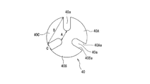
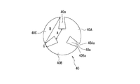
- the hard layer 40 three or more notches 40a radially extending from the outer edge toward the center are formed (in the example of FIGS. 11, 12 and 13, the number of notches 40a is three) , And the outer peripheral side portion of the hard layer 40 may be divided into a plurality of petal-like regions 40A, 40B, 40C,.
- the central portion of the hard layer 40 disposed inside the outer peripheral side portion of the hard layer 40 is not divided by the notch 40 a.
- the polishing surface 30 of the polishing pad 10 can be easily deformed in accordance with the curved surface shape of the surface of the object to be polished (object to be polished) 90. Therefore, when the surface of the curved object 90 is polished using such a polishing pad 10, the polishing surface 30 of the polishing pad 10 is three-dimensionally deformed and the surface of the curved object 90 is polished. It is possible to remove the waviness of the surface of the curved object 90 to be polished.
- the polishing method of the present embodiment can be applied to various objects 90 having different curvatures. It is applicable to the surface of.
- the polishing method of the present embodiment can be suitably applied to the surface of an object to be polished 90 having a plurality of curved surface portions having different curvatures, or to the surface of the object to be polished 90 having concave and convex portions. .
- the polishing surface 30 In order for the polishing surface 30 to deform in accordance with the curved surface shape of the surface of the workpiece 90 and follow the surface of the workpiece 90, the notches 40a are adjacent to the petal-like region (for example, petal-like regions 40A, 40B) When the split ends of each other (for example, the split end 40Aa of the petal-like area 40A and the split end 40Ba of the petal-like area 40B) are joined, the polishing surface 30 is formed to be a convex curved surface or a concave curved surface. Preferably (see FIGS. 11, 12 and 13).
- the surface of the soft layer 50 in contact with the hard layer 40 may have a convex curved surface or a concave curved surface.
- the planar shape of the notch 40a (the shape of the notch 40a in the vertical projection when the notch 40a is viewed from the viewpoint perpendicular to the polishing surface 30) is not particularly limited, and FIG. Although it may be V-shaped as shown, it may be a strip shown in FIG. 12 or a trapezoidal shape shown in FIG.
- the V-shaped notch 40a shown in FIG. 11 has a shape in which the outer edge side end is the widest and the width is gradually narrowed toward the center.
- the central end of the V-shaped notch 40a may be sharp as shown in FIG. 11, but may be arc-shaped.
- the strip-shaped notch 40a shown in FIG. 12 is shaped such that its width is constant from the outer edge side end to the center side edge.
- the center side end of the strip-shaped notch 40a may have an arc shape as shown in FIG. 12 (that is, it may be a U-shaped notch 40a), but has a polygonal shape such as a rectangular shape. May be
- the trapezoidal notch 40a shown in FIG. 13 has a shape in which the outer edge side end is the narrowest and the width gradually widens toward the center.
- the center side end of the trapezoidal notch 40a may have a polygonal shape such as a rectangular shape as shown in FIG. 15, but may have an arc shape.
- the shape of the plurality of petal-like regions 40A, 40B, 40C,... Formed by dividing the outer peripheral side portion of the hard layer 40 by the notches 40a is not particularly limited, but is as follows. May be That is, the distance A between the center side ends of the adjacent notches 40a (also referred to as the width at the center side end of the petal-like region) and the distance B between the outer side ends of the adjacent notches 40a
- the shape may be such that the ratio B / A to (which can be said to be the width at the outer edge side end of the petal-like region) is 1 or more.
- the ratio B / A is more preferably 1.3 or more.
- the shapes of the plurality of petal-like regions 40A, 40B, 40C,... May be as follows. That is, the shape may be such that the ratio A / C of the width C at the outer edge side end of the notch 40a to the distance A described above satisfies the formula 0.8 ⁇ A / C ⁇ 32.3. It is more preferable that the ratio A / C satisfies the expression 1.2 ⁇ A / C ⁇ 15.7.
- the shapes of the hard layer 40 and the polishing surface 30 are not particularly limited, but the hard layer 40 has a disk shape, and the outer surface of the hard layer 40 forming the polishing surface 30 (soft layer 50 and The surface opposite to the opposite surface, which is exposed to the outside, may be circular. When the polishing surface 30 is circular, the plurality of notches 40a may be formed equidistantly (at equal intervals) in the circumferential direction of the polishing surface 30.
- the radial length (the length in the radial direction of the polishing surface 30) of the notch 40a is not particularly limited, as shown in FIG.
- the length may be set to 2/3 or less of the radius of the polishing surface 30.
- the radial length of the notch 40 a is more preferably 1/2 or less of the radius of the polishing surface 30.
- the number of the notches 40a provided in the hard layer 40 is not particularly limited, and may be set to various numbers as shown in FIG. 14, but 3 or more and 6 or less are preferable.
- the notches 40a may be formed by cutting only the hard layer 40, they may be formed by cutting the hard layer 40 and the soft layer 50.
- the soft layer 50 includes the hard layer 40 of the soft layer 50.
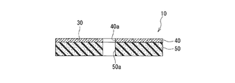
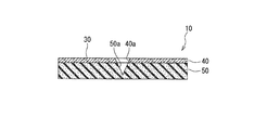
- a recess 50 a extending in the thickness direction of the soft layer 50 from the surface on the side of contact is formed continuously with the notch of the hard layer 40, and the notch of the hard layer 40 and the recess of the soft layer 50 are formed. 50a is united and constitutes notch 40a.
- the recess 50a of the soft layer 50 may be a through hole penetrating from the surface of the soft layer 50 in contact with the hard layer 40 to the surface on the opposite side, as shown in FIG. As shown to, the recessed part 50a with a bottom may be sufficient.
- the cross-sectional shape (the cross-sectional shape when cut in a plane orthogonal to the polishing surface 30) of the notch 40a in which the notch portion of the hard layer 40 and the recess 50a of the soft layer 50 are integrally formed is particularly limited. Although it may be V-shaped as shown in FIG. 15, it may be a polygonal shape such as a rectangle or an arc shape.
- the type of material constituting the hard layer 40 is not particularly limited, but the hardness according to the test method specified in Annex 2 “Spring hardness test type C test method” of JIS K7312: 1996 It may be described as a material having a hardness of 40 or more and 80 or less). If the hardness of the material constituting the hard layer 40 is within the above range, the abrading surface 30 can easily follow the abraded surface 90 a having a curved surface, and it becomes easy to remove the waviness of the surface of the abraded object 90 .
- the needle protruding from the hole at the center of the pressing surface is spring pressure.
- the measurement surface of the test piece should be at least as large as the pressure surface of the tester.
- a plurality of linear grooves 40 c having a width of 0.5 mm or more and 5 mm or less may be formed on the outer surface of the hard layer 40.
- the polishing surface 30 can easily follow the surface of the curved object 90, and it becomes easy to remove the waviness of the surface of the object 90.
- the polishing composition easily spreads along the linear grooves 40c to the central portion of the polishing surface 30, and foreign matter enters between the polishing surface 30 and the surface of the workpiece 90. Since foreign substances are easily discharged along the groove 40c, the generation of polishing scratches is suppressed even if the surface of the workpiece 90 is a relatively soft surface such as a coating film.
- the plurality of linear grooves 40c may be linear or curved. Then, linear or curved linear grooves 40c may be arranged parallel to each other and formed in stripes, or may be formed to intersect in a lattice shape. Alternatively, circular or elliptical linear grooves 40c may be formed concentrically.
- the linear groove 40c may be a groove having a depth penetrating from the outer surface of the hard layer 40 to the surface on the side in contact with the soft layer 50, or a groove with a bottom as shown in FIG. It is also good.
- the cross-sectional shape of the linear groove 40c (the cross-sectional shape when cut in a plane orthogonal to the polishing surface 30) is not particularly limited, and may be rectangular as shown in FIG. It may be a shape, an arc shape or the like.
- the water blocking layer 60 which suppresses the penetration of the slurry-like polishing composition into the soft layer 50 is a soft layer 50. It may be formed on the inner surface of the recess 50a (see FIG. 17).
- the water blocking layer 60 made of a water blocking material (for example, foam rubber) having a low water absorption rate, the polishing composition does not easily penetrate into the soft layer 50 during polishing. Become. Therefore, the polishing composition which is not used for polishing is reduced, and the utilization efficiency of the polishing composition is increased, so that the polishing cost can be suppressed.
- the type of the water blocking material is not particularly limited as long as it can suppress penetration of the polishing composition into the soft layer 50.
- chloroprene rubber foam ethylene / propylene rubber foam, silicone rubber foam And foamed rubbers such as fluorine rubber foam, polyurethane foam, polyethylene foam and the like.
- a water blocking layer may be provided on a portion of the surface of the soft layer 50 that is likely to be in contact with the polishing composition.
- the polishing pad 10 used in the polishing method of the present embodiment has the penetrating portion 1a which is a hole penetrating the hard layer 40 in the thickness direction in the region (center side) inside the outer edge of the polishing surface 30. May be formed. That is, the opening of the penetrating portion 1 a is not open at the outer edge of the hard layer 40 but is a closed opening.
- the through portion 1 a may be a hole extending in parallel to the thickness direction of the hard layer 40 as long as the through portion 1 a is formed in a region inside the outer edge of the polishing surface 30, or in the thickness direction of the hard layer 40. It may be a hole extending in the direction of inclination.
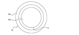
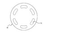
- the penetrating portion 1a is continuously annular along the circumferential direction of the polishing surface 30, as shown in FIG. 18, and the polishing surface 30 is a portion of the penetrating portion 1a by the penetrating portion 1a. It may be shaped so as to be divided into an outer annular polishing surface 30c and a circular polishing surface 30d inside the through portion 1a. Alternatively, as shown in FIG. 19 and FIG. 20, the penetrating portion 1a is not continuous along the circumferential direction of the polishing surface 30, and the penetrating surface 1 is not divided into a plurality of portions by the penetrating portion 1a It may be described as "non-cyclic".
- the planar shape of the opening of the penetrating portion 1a that is, the shape of the opening of the penetrating portion 1a in the vertical projection when the opening of the penetrating portion 1a is viewed from the viewpoint of a position perpendicular to the polishing surface 30, It is not particularly limited.
- annular (refer to Drawing 18) and non-annular are mentioned, for example.
- non-annular form circular (see FIG. 19), wedge-like (see FIG.
- oval, polygonal triangular, quadrangular, pentagonal, hexagonal, octagonal, etc.
- linear band-like
- shape arcuate shape, C shape, U shape, S shape etc.
- irregular shape etc. may be mentioned. If the opening of the penetrating portion 1a has a corner, breakage such as chipping is likely to occur in that portion, so it is preferable to have a shape that does not have a corner such as an annular shape or a circular shape.
- the shapes of the openings of the plurality of through parts 1a may be all the same, or some or all of them may be different.
- the size of the opening of the penetrating portion 1a and the number of the penetrating portions 1a are the penetrating portion with respect to the area of the polishing surface 30 (the total area of the region inside the outer edge of the polishing surface 30 including the opening of the penetrating portion 1a) It is preferable to set so that the ratio of the total area of the opening of 1a may be 3% or more and 35% or less. That is, the area of the polishing surface 30 and the area of the opening of the penetrating portion 1a are measured in a vertically projected view when the polishing surface 30 is viewed from the viewpoint of a position perpendicular to the polishing surface 30.
- the areas of the openings of all the through parts 1a are summed, and the total area of the openings of the total through parts 1a is divided by the area of the polishing surface 30, and the opening of the through part 1a relative to the area of the polishing surface 30 Calculate the percentage of the total area of the department.
- the ratio of the total area of the opening of the penetrating portion 1a to the area of the polishing surface 30 is 3% or more, the flexibility of the hard layer 40 becomes good, and it becomes easy to follow the curved surface 90a. .
- the ratio of the total area of the openings of the penetrating portion 1a to the area of the polishing surface 30 is 35% or less, the polishing performance of the hard layer 40 becomes good and the waviness of the curved surface 90a is removed Cheap.
- it is more preferable to set so that the ratio of the total area of the opening part of the penetration part 1a with respect to the area of the grinding surface 30 may be 6% or more and 20%.
- the mode of the arrangement of the openings of the penetrating portion 1a in the polishing surface 30 is not particularly limited, but the distance from the outer edge of the polishing surface 30 so that the softness and polishing performance of the hard layer 40 become suitable. It is preferable to appropriately set the distance from the center of the polishing surface 30, the distance between the openings of the through portion 1a, and the like.
- the polishing surface 30 is divided into an annular polishing surface 30c outside the through portion 1a and a circular polishing surface 30d inside the through portion 1a.
- the shape of the through portion 1a at this time is not particularly limited, and may be a perfect circular shape or an elliptical shape.
- polishing surface 30 may be 2.5% or more and 15% or less, and it is more preferable that it is 8% or more and 13% or less. Within this range, the polishing surface 30 easily follows the curved surface to be polished 90a, and the undulation of the curved surface 90a is easily removed.
- the position of the annular through portion 1 a in the polishing surface 30 is not particularly limited as long as it is a region inside (central side) of the outer edge of the polishing surface 30, but the annular abrasive surface 30 c outside the through portion 1 a It is preferable to arrange the annular penetration part 1a in the position where the center of the center and the center of the circular polishing surface 30d inside the penetration part 1a are common.
- the hard layer 40 having the annular polishing surface 30c outside the through portion 1a and the hard layer 40 having the circular polishing surface 30d inside the through portion 1a may be formed of the same material. , And may be formed of different materials. Compared with the A hardness of the hard layer 40 having the annular grinding surface 30c outside the penetration portion 1a, the hardness A of the hard layer 40 having the circular grinding surface 30d inside the penetration portion 1a is larger It is preferable because the undulation of the curved surface 90a can be removed efficiently.
- the size of the opening of the penetrating portion 1a and the number of the penetrating portions 1a are not particularly limited, but the number of the penetrating portions 1a is 3 or more The number is preferably 16 or less, more preferably 5 or more and 10 or less. If the number of the penetrating portions 1a is three or more, the flexibility of the hard layer 40 becomes good, so it becomes easy to follow the curved surface 90a. On the other hand, if the number of penetrations 1a is 16 or less, the polishing performance of the hard layer 40 is good, and the undulation of the curved surface 90a is easily removed.
- the sizes of the openings of the plurality of penetrations 1a may be all the same, or some or all of them may be different.
- the mode of the arrangement of the non-annular penetrations 1a is not particularly limited.
- the openings of the plurality of non-annular penetrations 1a may be arranged in a straight line on the polishing surface 30, or may be arranged in a curve. It may also be arranged in a ring.
- the polishing surface 30 is an annular polishing surface 30c outside the penetration 1a divided by the annular penetration 1a, and the inside of the penetration 1a.
- a plurality of openings may be regularly or irregularly formed in the polishing surface 30 such that the openings of the plurality of non-annular penetrations 1 a are arranged in a straight line, a curved line, or an annular line.
- a plurality of opening groups in which the openings of the plurality of non-annular penetrations 1 a are arranged in a straight line or a curved line may be arranged in parallel to the polishing surface 30.
- a plurality of opening groups in which the openings of the plurality of non-annular penetrations 1 a are annularly arranged may be arranged concentrically or in a row on the polishing surface 30.
- the openings of the plurality of non-annular penetrations 1a are preferably arranged on the polishing surface 30 so as to have symmetry such as line symmetry or point symmetry as a whole.
- the opening of the non-annular penetrating part 1a is such that a virtual straight line connecting the centers of the openings of the adjacent non-annular penetrating parts 1a sequentially forms a regular polygon such as a square, regular hexagon, or regular octagon. It is preferable that it is arrange
- the centers of the openings of the plurality of non-annular penetrations 1 a be disposed at positions corresponding to the vertices of the regular polygon virtually disposed on the polishing surface 30. In this case, it is preferable that the center of the polishing surface 30 coincides with the center of the regular polygon.
- the polishing pads 10 shown in FIG. 19 are arranged at positions corresponding to the apexes of a regular octagon, respectively, and the polishing pads 10 shown in FIG.
- the openings of the non-annular penetrations 1a are arranged at positions corresponding to the apexes of a regular hexagon.
- the soft layer 50 may be provided with a recess.
- the concave portion of the soft layer 50 may be a penetrating portion penetrating the soft layer 50 in the thickness direction, or a bottomed hole formed on the surface of the soft layer 50 in contact with the hard layer 40. It may be.
- the cross-sectional shape (the cross-sectional shape when cut in a plane perpendicular to the polishing surface 30) is not particularly limited, and may be V-shaped, It may be a polygonal shape such as a rectangle or an arc shape.
- the recess of the soft layer 50 may be formed continuously with the annular or non-annular penetration portion 1a of the hard layer 40 (ie, may be arranged at the same position on the polishing surface 30) , And may be formed discontinuously.
- the side surface of the soft layer 50 is a cylindrical surface or a conical surface when the soft layer 50 is cylindrical or frusto-conical, and a flat surface when the soft layer 50 is prismatic or truncated pyramidal, but these side surfaces are flat.
- the invention is not limited to the surface, and it may be a convex surface protruding toward the outside of the soft layer 50 or a concave surface recessed toward the inside of the soft layer 50.
- the shape of the soft layer 50 is a frustum shape
- the inclination angle of the side surface of the soft layer 50 with respect to the central axis of the frustum is not particularly limited. You can adjust the sex.
- the polishing surface 30 of the polishing pad 10 is three-dimensionally deformed to form a curved surface. Since it follows the polishing surface 90a, it is possible to sufficiently remove the waviness of the curved surface to be polished 90a, and it is preferable because breakage such as chipping does not easily occur in the polishing pad 10.
- ⁇ Abrasive> As abrasive grains, any of the following was used.
- Aluminum oxide 60 to 100% of alpha conversion rate, average secondary particle size (D 50 ) 0.3 ⁇ m, 7.5 ⁇ m, 12.7 ⁇ m or 37 ⁇ m ⁇
- Ceria average secondary particle size (D 50 ) 1.6 ⁇ m ⁇
- Mixture of alumina oxide and zircon average secondary particle size (D 50 ) 3.2 ⁇ m
- the alpha conversion rate of the aluminum oxide particles was calculated from the integrated intensity ratio of (113) plane diffraction line by X-ray diffraction measurement using an X-ray analyzer (Ultima-IV, manufactured by Rigaku Corporation). Further, the average secondary particle diameter (D 50 ) of each abrasive grain was measured by a laser diffraction / scattering method using LA-950V2 (manufactured by Horiba, Ltd.).
- ⁇ Dispersing agent> As a dispersant, any of the following was used.
- Hectorite sodium (Na) hectorite, average primary particle size 0.08 ⁇ m or 3 ⁇ m (both measured by SEM), aspect ratio 80 (0.08 ⁇ m) or 1000 (3 ⁇ m), addition amount 0.
- Bentonite Sodium (Na) bentonite, average primary particle diameter 1 ⁇ m (measured value by SEM), viscosity 300 mPa ⁇ s (measured value with 4 mass% water dispersion, BM type viscometer, 60 rpm, 25 ° C.), swelling power 63 ml / 2 g, addition amount 0.1 mass% or 1 mass% Na tetra silicon mica: sodium (Na) tetra silicon mica, average primary particle diameter 11 ⁇ m (measured value by laser diffractometer), aspect ratio 2000, addition amount 1 mass% -Other compounds Na polyacrylate Na: sodium polyacrylate, molecular weight 3000, addition amount 0.1 mass% Pyrophosphate Na: Sodium pyrophosphate decahydrate, molecular weight 446, addition amount 0.1% by mass
- Emulsification stabilizer Glycerin (addition amount 2.0% by mass)
- -Oil agent Spindle oil (addition amount 1.2 mass%) and castor oil (addition amount 0.3 mass%)
- polishing was performed under the following polishing conditions, and the removal amount was determined.
- the polishing apparatus used for polishing is an apparatus in which a double action polisher is attached to the tip of an arm of an industrial robot “M-20iA” manufactured by FANUC LTD.
- a polishing pad (see FIG. 3) provided with grating grooves on the polishing surface is attached to this double action polisher, and the polishing surface of the polishing pad is applied to the surface to be polished of the polishing object by the pressing force applied to the arm. While pressing and supplying the polishing composition onto the surface to be polished, polishing was performed by rotating the double action polisher.
- the specific polishing conditions are as follows.
- polishing pad mounted on the double action polisher may be, for example, the polishing pad shown in FIGS. 2 and 4 to 17 described in the present embodiment, in addition to the polishing pad having the grating grooves on the polishing surface.
- the polishing pad used is a suede pad and has a C hardness of 58.
- the object to be polished was coated with a synthetic resin paint (a clear coating film for repair of automobile dealers in Japan), and the thickness of the coating film was 20 ⁇ m. That is, the surface to be polished is a coating film surface made of a synthetic resin.
- the film thickness of each film before and after polishing was measured using an electromagnetic induction type film thickness measuring device. Then, the removal amount (polishing amount) was evaluated from the film thickness difference. The polishing performance was accepted when the machining allowance was 1.7 ⁇ m or more.
- the scattering prevention performance of the polishing composition was regarded as “B”. Further, when no trace of scattering of the polishing composition was found around the polishing composition, the scattering prevention performance of the polishing composition was regarded as “A”.
- Example 2-1 the method of preparing the polishing composition and the polishing conditions are the same as in the first embodiment except that the polishing pad attached to the double action polisher is a non-woven pad having a C hardness of 23 (see FIG. 3). Or the same in the criteria of each evaluation. Therefore, the description of the method for preparing the polishing composition and the polishing conditions in the second embodiment, the criteria for each evaluation, and the like will be omitted here.
- the polishing composition of Example 2-1 the same composition as the polishing composition of Example 1-2 was used.
- the polishing composition of Comparative Example 2-1 the same composition as the polishing composition of Comparative Example 1-1 was used.
- Example 3-1 the method for preparing the polishing composition and the polishing composition according to the first embodiment and the polishing are employed except that the polishing pad attached to the double action polisher is a foamed polyurethane pad having a C hardness of 23 (see FIG. 3).
- the conditions are the same or the criteria of each evaluation. Therefore, the description of the method of preparing the polishing composition, the polishing conditions, the criteria for each evaluation, and the like in the third embodiment will be omitted here.
- the polishing composition of Example 3-1 the same composition as the polishing composition of Example 1-2 was used.
- the polishing composition of Comparative Example 3-1 the same composition as the polishing composition of Comparative Example 1-1 was used.
- Example 4-1 the same one as the polishing composition of Example 1-2 was used.
- the same polishing composition as in Example 1-7 was used as the polishing composition in Example 4-2.
- the polishing composition of Comparative Example 4-1 the same composition as the polishing composition of Comparative Example 1-1 was used.
- polishing was performed under the following polishing conditions, and the front surface removability and the scattering were evaluated.
- the polishing apparatus used for polishing is a hand polisher.
- a polishing pad (see FIG. 3) having a grating groove on the polishing surface is attached to the hand polisher, and the pressing force applied to the hand polisher brings the polishing surface of the polishing pad to the surface to be polished of the object to be polished. While pressing and supplying the polishing composition onto the surface to be polished, polishing was performed by rotating the hand polisher.
- the specific polishing conditions are as follows. Polisher speed: 650 rpm Flow rate of polishing composition: 2 ml / 15 sec Polishing time: 1 minute Polishing conditions such as polishing pressure, polishing rate, polishing time, etc. were the same for all tests.
- the polishing pad attached to the hand polisher may be, for example, the polishing pad shown in FIGS. 2 and 4 to 17 described in the present embodiment, in addition to the polishing pad having the grating grooves on the polishing surface.
- the polishing pad used is a foamed polyurethane buff and has a C hardness of 17.
- the object to be polished used is aluminum alloy A6061. That is, the surface to be polished is a surface made of an alloy.
- Example 5-1 the same composition as the polishing composition of Example 1-2 was used.
- the polishing composition of Comparative Example 5-1 the same composition as the polishing composition of Comparative Example 1-1 was used.
- Example 5-1 and Comparative Example 5-1 were used to polish the polishing conditions of the fourth example under the same polishing conditions as the rotation speed and polishing time of the polisher, etc. was evaluated.
- the object to be polished is iron alloy SUS304. That is, the surface to be polished is a surface made of an alloy.
- polishing performance such as the removal cost is improved as compared with the comparative examples (Comparative Examples 1-6, 1-7, 1-9 to 1-11) in which the layered silicate compound is not added.
- anti-scattering performance was improved as compared with Comparative Examples (Comparative Examples 1-5, 1-8) in which no thickener was added.
Landscapes
- Chemical & Material Sciences (AREA)
- Engineering & Computer Science (AREA)
- Organic Chemistry (AREA)
- Materials Engineering (AREA)
- Mechanical Engineering (AREA)
- Finish Polishing, Edge Sharpening, And Grinding By Specific Grinding Devices (AREA)
- Mechanical Treatment Of Semiconductor (AREA)
Abstract
合金または樹脂、さらには金属や半金属、その酸化物等の材料の表面に対し優れた研磨性能を有しつつ、研磨時における研磨用組成物の飛散を低減させた研磨用組成物の提供。本実施形態に係る研磨用組成物は、砥粒と、疎水性を有する第1の液体と、界面活性剤と、層状ケイ酸塩化合物と、増粘剤と、親水性を有する第2の液体とを含む。
Description
本発明は、研磨用組成物、研磨用組成物の製造方法、および研磨方法に関する。
自動車のボディー等の塗装面においては、表面の光沢度を良くすることが望まれている。塗装面の光沢度を高める手法の一つとして、バフ(研磨輪)およびバフを回転可能に装着したポリッシャ(研磨機)を用いて、塗装面とバフとの間に研磨用組成物を介在させながら、ポリッシャによりバフを回転させることにより、研磨(バフ研磨)することが知られている。
このような研磨用組成物としては、例えば、特許文献1に記載した研磨用組成物がある。
このような研磨用組成物としては、例えば、特許文献1に記載した研磨用組成物がある。
上記特許文献1に記載の研磨用組成物は、他の研磨用組成物と比べて粘度が高いため、自動車のボディー等の立体形状をした研磨対象物を研磨する際に生ずる研磨用組成物の飛散が少ない。
しかしながら、該研磨用組成物は、その研磨性能(研磨能率)が不十分であるという問題があった。
本発明は、上記問題に鑑みてなされたものであり、その目的は、研磨性能を維持しつつ、研磨時における研磨用組成物の飛散を低減させる手段を提供することにある。
しかしながら、該研磨用組成物は、その研磨性能(研磨能率)が不十分であるという問題があった。
本発明は、上記問題に鑑みてなされたものであり、その目的は、研磨性能を維持しつつ、研磨時における研磨用組成物の飛散を低減させる手段を提供することにある。
上記課題を解決すべく、本発明者は鋭意研究を積み重ねた。その結果、砥粒、疎水性を有する第1の液体、界面活性剤、層状ケイ酸塩化合物、増粘剤、および親水性を有する第2の液体を含む研磨用組成物を使用することで、上記課題が解決されうることを見出した。そして、上記知見に基づいて、本発明を完成するに至った。
本発明によれば、研磨性能を維持しつつ、研磨時における研磨用組成物の飛散を低減させる手段が提供される。
本発明の一態様は、砥粒、疎水性を有する第1の液体、界面活性剤、層状ケイ酸塩化合物、増粘剤、および親水性を有する第2の液体を含む、研磨用組成物である。かような構成を有する本発明の一態様に係る研磨用組成物は、高い研磨速度、即ち大きい取り代といった研磨性能を維持しつつ、研磨時における研磨用組成物の飛散を低減させることができる。
[研磨対象物]
本実施形態に係る研磨対象物は、特に制限されないが、合金材料、樹脂材料、金属や半金属やその酸化物等の材料およびガラス材料からなる群より選択される少なくとも1種を含むことが好ましく、さらにこれらの素材の複合材料であってもよい。特に、自動車のボディー等の塗装面に用いられる樹脂材料が好ましい。
ここで、合金とは、1種の金属元素に対して、1種以上の金属元素や、炭素、窒素、ケイ素等の非金属元素を共有させた共有体であり、純金属に対し機械的強度や耐薬品性、耐食性、耐熱性等の性質を向上させることを目的として製造される。それらの中でもアルミニウム合金は、軽量かつ優れた強度を有することから、建材や容器等の構造材料、自動車、船舶、航空機等の輸送機器の他、各種電化製品や、電子部品等様々な用途に用いられている。また、チタン合金は、軽量なうえに耐食性に優れていることから、精密機器、装飾品、工具、スポーツ用品、医療部品等に広く用いられている。また、鉄系合金であるステンレスやニッケル合金は、優れた耐食性を有することから、構造材料や輸送機器の他、工具、機械器具、調理器具等の様々な用途で使用されている。また、銅合金は、電気伝導性、熱伝導性、耐食性に優れているほか、加工性に優れておりまた仕上げの美しさから、装飾品、食器、楽器や電気材料の部品等に広く用いられている。さらに、最近では上記のような用途で、樹脂を含む材料も使用されてきている。
本実施形態に係る研磨対象物は、特に制限されないが、合金材料、樹脂材料、金属や半金属やその酸化物等の材料およびガラス材料からなる群より選択される少なくとも1種を含むことが好ましく、さらにこれらの素材の複合材料であってもよい。特に、自動車のボディー等の塗装面に用いられる樹脂材料が好ましい。
ここで、合金とは、1種の金属元素に対して、1種以上の金属元素や、炭素、窒素、ケイ素等の非金属元素を共有させた共有体であり、純金属に対し機械的強度や耐薬品性、耐食性、耐熱性等の性質を向上させることを目的として製造される。それらの中でもアルミニウム合金は、軽量かつ優れた強度を有することから、建材や容器等の構造材料、自動車、船舶、航空機等の輸送機器の他、各種電化製品や、電子部品等様々な用途に用いられている。また、チタン合金は、軽量なうえに耐食性に優れていることから、精密機器、装飾品、工具、スポーツ用品、医療部品等に広く用いられている。また、鉄系合金であるステンレスやニッケル合金は、優れた耐食性を有することから、構造材料や輸送機器の他、工具、機械器具、調理器具等の様々な用途で使用されている。また、銅合金は、電気伝導性、熱伝導性、耐食性に優れているほか、加工性に優れておりまた仕上げの美しさから、装飾品、食器、楽器や電気材料の部品等に広く用いられている。さらに、最近では上記のような用途で、樹脂を含む材料も使用されてきている。
以下、合金材料、樹脂材料、金属や半金属やその酸化物等の材料およびガラス材料について説明する。
〔合金材料〕
合金材料は、主成分となる金属種と、主成分とは異なる金属種と、を含有する。
合金材料は、主成分となる金属種に基づいて名称が付される。合金材料としては、例えば、アルミニウム合金、鉄合金、チタン合金、ニッケル合金、および銅合金等が挙げられる。これら合金材料は、単独でもまたは2種以上組み合わせて適用してもよい。中でも、アルミニウム合金および鉄合金からなる群より選択される少なくとも1種を含むことが好ましい。また、主成分となる金属種と、主成分とは異なる金属種とのビッカース硬度(HV)が5以上異なる合金材料が好ましい。
〔合金材料〕
合金材料は、主成分となる金属種と、主成分とは異なる金属種と、を含有する。
合金材料は、主成分となる金属種に基づいて名称が付される。合金材料としては、例えば、アルミニウム合金、鉄合金、チタン合金、ニッケル合金、および銅合金等が挙げられる。これら合金材料は、単独でもまたは2種以上組み合わせて適用してもよい。中でも、アルミニウム合金および鉄合金からなる群より選択される少なくとも1種を含むことが好ましい。また、主成分となる金属種と、主成分とは異なる金属種とのビッカース硬度(HV)が5以上異なる合金材料が好ましい。
アルミニウム合金は、アルミニウムを主成分とし、主成分と異なる金属種として、好ましくは、マグネシウム、ケイ素、銅、亜鉛、マンガン、クロム、および鉄からなる群より選択される少なくとも1種が含有される。アルミニウム合金中における、上記の主成分とは異なる金属種の含有量の下限は、特に制限されないが、アルミニウム合金全体に対して0.1質量%以上であることが好ましい。また、アルミニウム合金中における、上記の主成分とは異なる金属種の含有量の上限は、特に制限されないが、アルミニウム合金全体に対して10質量%以下であることが好ましい。
アルミニウム合金の具体例としては、例えば、JIS H4000:2006に記載されているような、Al-Cu系、Al-Cu-Mg系の合金番号2000番台、Al-Mn系の合金番号3000番台、Al-Si系の合金番号4000番台、Al-Mg系の合金番号5000番台、Al-Mg-Si系の合金番号6000番台、Al-Zn-Mg系の合金番号7000番台、Al-Fe-Mn系の合金番号8000番台等が挙げられる。
鉄合金は、鉄を主成分とし、主成分とは異なる金属種として、好ましくは、クロム、ニッケル、モリブデン、およびマンガンからなる群より選択される少なくとも1種が含有される。鉄合金中における、上記の主成分とは異なる金属種の含有量の下限は、特に制限されないが、鉄合金全体に対して10質量%以上であることが好ましい。また、鉄合金中における、上記の主成分とは異なる金属種の含有量の上限は、特に制限されないが、鉄合金全体に対して50質量%以下であることが好ましい。
鉄合金は、鉄を主成分とし、主成分とは異なる金属種として、好ましくは、クロム、ニッケル、モリブデン、およびマンガンからなる群より選択される少なくとも1種が含有される。鉄合金中における、上記の主成分とは異なる金属種の含有量の下限は、特に制限されないが、鉄合金全体に対して10質量%以上であることが好ましい。また、鉄合金中における、上記の主成分とは異なる金属種の含有量の上限は、特に制限されないが、鉄合金全体に対して50質量%以下であることが好ましい。
鉄合金は、好ましくはステンレス鋼である。ステンレス鋼の具体的な例としては、例えば、JIS G4303:2005に記載される種類の記号において、SUS201、SUS303、303Se、SUS304、SUS304L、SUS304NI、SUS305、SUS305JI、SUS309S、SUS310S、SUS316、SUS316L、SUS321、SUS347、SUS384、SUSXM7、SUS303F、SUS303C、SUS430、SUS430F、SUS434、SUS410、SUS416、SUS420J1、SUS420J2、SUS420F、SUS420C、SUS631J1等が挙げられる。
チタン合金は、チタンを主成分とし、主成分とは異なる金属種として、例えば、アルミニウム、鉄、およびバナジウム等が含有される。チタン合金中における主成分とは異なる金属種の含有量は、チタン合金全体に対して例えば3.5質量%以上30質量%以下である。チタン合金としては、例えば、JIS H4600:2012に記載される種類において、11~23種、50種、60種、61種、および80種のものが挙げられる。
ニッケル合金は、ニッケルを主成分とし、主成分とは異なる金属種として、例えば、鉄、クロム、モリブデン、およびコバルトから選択される少なくとも1種が含有される。ニッケル合金中における主成分とは異なる金属種の含有量は、ニッケル合金全体に対して例えば20質量%以上75質量%以下である。ニッケル合金としては、例えば、JIS H4551:2000に記載される合金番号において、NCF600,601、625、750、800、800H、825、NW0276、4400、6002、6022等が挙げられる。
ニッケル合金は、ニッケルを主成分とし、主成分とは異なる金属種として、例えば、鉄、クロム、モリブデン、およびコバルトから選択される少なくとも1種が含有される。ニッケル合金中における主成分とは異なる金属種の含有量は、ニッケル合金全体に対して例えば20質量%以上75質量%以下である。ニッケル合金としては、例えば、JIS H4551:2000に記載される合金番号において、NCF600,601、625、750、800、800H、825、NW0276、4400、6002、6022等が挙げられる。
銅合金は、銅を主成分とし、主成分とは異なる金属種として、例えば、鉄、鉛、亜鉛、および錫から選択される少なくとも1種が含有される。銅合金中における主成分とは異なる金属種の含有量は、銅合金全体に対して例えば3質量%以上50質量%以下である。銅合金としては、例えば、JIS H3100:2006に記載される合金番号において、C2100、2200、2300、2400、2600、2680、2720、2801、3560、3561、3710、3713、4250、4430、4621、4640、6140、6161、6280、6301、7060、7150、1401、2051、6711、6712等が挙げられる。
〔樹脂材料〕
樹脂材料の種類としては特に制限されず、熱硬化性樹脂、熱可塑性樹脂のいずれであってもよい。
熱硬化性樹脂の例としては、例えば、エポキシ樹脂、ポリイミド樹脂、フェノール樹脂、アミノ樹脂、不飽和ポリエステル樹脂、熱硬化性ポリウレタン樹脂等が挙げられる。
熱可塑性樹脂の例としては、例えば、ポリスチレン樹脂、アクリロニトリル-ブタジエン-スチレン共重合体樹脂(ABS樹脂)、(メタ)アクリル樹脂(メタクリルおよび/またはアクリル樹脂)、有機酸ビニルエステル樹脂またはその誘導体、ビニルエーテル樹脂、ポリ塩化ビニル、ポリ塩化ビニリデン、ポリフッ化ビニリデン等のハロゲン含有樹脂、ポリエチレン、ポリプロピレン等のオレフィン樹脂、ポリカーボネート樹脂、ポリエチレンテレフタレート、ポリエチレンナフタレート等の飽和ポリエステル樹脂、ポリアミド樹脂、熱可塑性ポリウレタン樹脂、ポリスルホン樹脂(ポリエーテルスルホン、ポリスルホン等)、ポリフェニレンエーテル樹脂(2,6-キシレノールの重合体等)、セルロース誘導体(セルロースエステル類、セルロースカーバメート類、セルロースエーテル類等)、シリコーン樹脂(ポリジメチルシロキサン、ポリメチルフェニルシロキサン等)等が挙げられる。
樹脂材料の種類としては特に制限されず、熱硬化性樹脂、熱可塑性樹脂のいずれであってもよい。
熱硬化性樹脂の例としては、例えば、エポキシ樹脂、ポリイミド樹脂、フェノール樹脂、アミノ樹脂、不飽和ポリエステル樹脂、熱硬化性ポリウレタン樹脂等が挙げられる。
熱可塑性樹脂の例としては、例えば、ポリスチレン樹脂、アクリロニトリル-ブタジエン-スチレン共重合体樹脂(ABS樹脂)、(メタ)アクリル樹脂(メタクリルおよび/またはアクリル樹脂)、有機酸ビニルエステル樹脂またはその誘導体、ビニルエーテル樹脂、ポリ塩化ビニル、ポリ塩化ビニリデン、ポリフッ化ビニリデン等のハロゲン含有樹脂、ポリエチレン、ポリプロピレン等のオレフィン樹脂、ポリカーボネート樹脂、ポリエチレンテレフタレート、ポリエチレンナフタレート等の飽和ポリエステル樹脂、ポリアミド樹脂、熱可塑性ポリウレタン樹脂、ポリスルホン樹脂(ポリエーテルスルホン、ポリスルホン等)、ポリフェニレンエーテル樹脂(2,6-キシレノールの重合体等)、セルロース誘導体(セルロースエステル類、セルロースカーバメート類、セルロースエーテル類等)、シリコーン樹脂(ポリジメチルシロキサン、ポリメチルフェニルシロキサン等)等が挙げられる。
上記樹脂は、単独でもまたは2種以上組み合わせても使用することができる。これら樹脂の中でも、耐衝撃性や耐候性の観点から熱可塑性樹脂が好ましく、ポリカーボネート樹脂がより好ましい。
樹脂材料を含む研磨対象物は、例えば、樹脂材料から形成された部材(樹脂製部材)の形態であってもよいし、金属基板等の表面に樹脂塗膜を有する複合材料の形態であってもよいし、特に制限されない。塗膜に用いられる樹脂としては、熱硬化性ポリウレタン樹脂、(メタ)アクリル樹脂等が挙げられる。樹脂塗膜は透明なクリア塗膜であってもよい。塗装部材の種類(すなわち樹脂塗膜の用途)は特に限定されるものではないが、立体形状の樹脂材料に好ましく用いられることができ、例えば、自動車の車体、鉄道車両、航空機、樹脂製部材が挙げられる。自動車の車体の表面に被覆された樹脂塗膜は、面積が大きく且つ曲面を有するが、本実施形態の研磨用組成物は、このような樹脂塗膜の外表面の研磨に対して好適である。
樹脂材料を含む研磨対象物は、例えば、樹脂材料から形成された部材(樹脂製部材)の形態であってもよいし、金属基板等の表面に樹脂塗膜を有する複合材料の形態であってもよいし、特に制限されない。塗膜に用いられる樹脂としては、熱硬化性ポリウレタン樹脂、(メタ)アクリル樹脂等が挙げられる。樹脂塗膜は透明なクリア塗膜であってもよい。塗装部材の種類(すなわち樹脂塗膜の用途)は特に限定されるものではないが、立体形状の樹脂材料に好ましく用いられることができ、例えば、自動車の車体、鉄道車両、航空機、樹脂製部材が挙げられる。自動車の車体の表面に被覆された樹脂塗膜は、面積が大きく且つ曲面を有するが、本実施形態の研磨用組成物は、このような樹脂塗膜の外表面の研磨に対して好適である。
〔金属や半金属やその酸化物〕
金属としては、例えば、アルミニウム、鉄、ジルコニウム、銅、ニッケル、金、銀、ビスマス、マンガン、亜鉛等が挙げられる。
半金属の種類としては、例えば、シリコン(Si)、ゲルマニウム(Ge)等のIV族半導体、セレン化亜鉛(ZnSe)、硫化カドミウム(CdS)、酸化亜鉛(ZnO)等のII-VI族化合物半導体、ガリウムヒ素(GaAs)、リン化インジウム(InP)、窒化ガリウム(GaN)等のIII-V族化合物半導体、炭化ケイ素(SiC)、シリコンゲルマニウム(SiGe)等のIV族化合物半導体、銅・インジウム・セレン(CuInSe2)等のカルコパイライト系半導体等が挙げられる。
また、これらの材料の酸化物に対しても好適に使用できる。
金属としては、例えば、アルミニウム、鉄、ジルコニウム、銅、ニッケル、金、銀、ビスマス、マンガン、亜鉛等が挙げられる。
半金属の種類としては、例えば、シリコン(Si)、ゲルマニウム(Ge)等のIV族半導体、セレン化亜鉛(ZnSe)、硫化カドミウム(CdS)、酸化亜鉛(ZnO)等のII-VI族化合物半導体、ガリウムヒ素(GaAs)、リン化インジウム(InP)、窒化ガリウム(GaN)等のIII-V族化合物半導体、炭化ケイ素(SiC)、シリコンゲルマニウム(SiGe)等のIV族化合物半導体、銅・インジウム・セレン(CuInSe2)等のカルコパイライト系半導体等が挙げられる。
また、これらの材料の酸化物に対しても好適に使用できる。
〔ガラス材料〕
ガラス材料としては、例えば、青板ガラス、石英ガラス、強化ガラス、結晶化ガラス、アルミノシリケートガラス、ガラス状カーボン等が挙げられる。
ガラス材料としては、例えば、青板ガラス、石英ガラス、強化ガラス、結晶化ガラス、アルミノシリケートガラス、ガラス状カーボン等が挙げられる。
次に、本実施形態の研磨用組成物の構成について、詳細に説明する。
[砥粒]
本実施形態の研磨用組成物は、砥粒を含む。砥粒は、研磨対象物を機械的に研磨する作用を有する。
本実施形態で用いられる砥粒の具体的な例としては、例えば、酸化アルミニウム(アルミナ)、酸化ケイ素(シリカ)、酸化セリウム(セリア)、酸化ジルコニウム、酸化チタン(チタニア)、酸化スズ、酸化マンガン等の金属酸化物、炭化ケイ素、炭化チタン等の金属炭化物、窒化ケイ素、窒化チタン等の金属窒化物、ホウ化チタン、ホウ化タングステン等の金属ホウ化物、ジルコン等のケイ酸塩化合物、ダイヤモンド等が挙げられる。該砥粒は、単独でもまたは2種以上混合して用いてもよい。また、該砥粒は、市販品を用いてもよいし合成品を用いてもよい。
[砥粒]
本実施形態の研磨用組成物は、砥粒を含む。砥粒は、研磨対象物を機械的に研磨する作用を有する。
本実施形態で用いられる砥粒の具体的な例としては、例えば、酸化アルミニウム(アルミナ)、酸化ケイ素(シリカ)、酸化セリウム(セリア)、酸化ジルコニウム、酸化チタン(チタニア)、酸化スズ、酸化マンガン等の金属酸化物、炭化ケイ素、炭化チタン等の金属炭化物、窒化ケイ素、窒化チタン等の金属窒化物、ホウ化チタン、ホウ化タングステン等の金属ホウ化物、ジルコン等のケイ酸塩化合物、ダイヤモンド等が挙げられる。該砥粒は、単独でもまたは2種以上混合して用いてもよい。また、該砥粒は、市販品を用いてもよいし合成品を用いてもよい。
これら砥粒の中でも、様々な粒子径を有するものが容易に入手でき、優れた研磨速度が得られるという観点から、金属酸化物および金属炭化物からなる群より選択される少なくとも1種が好ましく、炭化ケイ素、二酸化ケイ素、または金属酸化物がより好ましく、酸化アルミニウム、酸化セリウム、および酸化ジルコニウムの少なくとも1種がより好ましい。また、アルミナとジルコンの混合物等も好ましく使用できる。
砥粒の体積平均粒子径(平均二次粒子径)の下限は、0.05μm以上であればよく、0.1μm以上であることが好ましく、0.3μm以上であることがより好ましい。砥粒の体積平均粒子径が大きくなるにつれて、研磨対象物の研磨速度が向上する。また、砥粒の体積平均粒子径(平均二次粒子径)の上限は、50.0μm以下であればよく、40.0μm以下であることが好ましく、15.0μm以下であることがより好ましく、8.0μm以下であることがさらに好ましい。砥粒の体積平均粒子径が小さくなるにつれて、低欠陥で粗度の小さな表面を得ることが容易となる。上記より、砥粒の体積平均粒子径は、0.2μm以上15.0μm以下であることがさらに好ましく、0.3μm以上8.0μm以下が特に好ましい。
砥粒の体積平均粒子径(平均二次粒子径)の下限は、0.05μm以上であればよく、0.1μm以上であることが好ましく、0.3μm以上であることがより好ましい。砥粒の体積平均粒子径が大きくなるにつれて、研磨対象物の研磨速度が向上する。また、砥粒の体積平均粒子径(平均二次粒子径)の上限は、50.0μm以下であればよく、40.0μm以下であることが好ましく、15.0μm以下であることがより好ましく、8.0μm以下であることがさらに好ましい。砥粒の体積平均粒子径が小さくなるにつれて、低欠陥で粗度の小さな表面を得ることが容易となる。上記より、砥粒の体積平均粒子径は、0.2μm以上15.0μm以下であることがさらに好ましく、0.3μm以上8.0μm以下が特に好ましい。
なお、本明細書において、砥粒の体積平均粒子径は、体積基準の粒度分布に基づく積算50%粒子径(D50)と定義する。砥粒のD50は、市販の粒度測定装置を利用して測定することができる。かかる粒度測定装置は、動的光散乱法、レーザー回折法、レーザー散乱法、または細孔電気抵抗法等のいずれの手法に基づくものであってもよい。D50の測定方法および測定装置の一例として、実施例に記載の測定方法および測定装置が挙げられる。
研磨用組成物中の砥粒の含有量の下限は、0.1質量%以上であることが好ましく、5質量%以上であることがより好ましく、10質量%以上であることがさらに好ましい。砥粒の含有量が多くなるにつれて、研磨速度が上昇する。
また、研磨用組成物中の砥粒の含有量の上限は、50質量%以下であることが好ましく、35質量%以下であることがより好ましい。砥粒の含有量が少なくなるにつれて、研磨用組成物の製造コストが低減するのに加えて、研磨用組成物を用いた研磨により傷等の欠陥が少ない表面を得ることが容易となる。
また、研磨用組成物中の砥粒の含有量の上限は、50質量%以下であることが好ましく、35質量%以下であることがより好ましい。砥粒の含有量が少なくなるにつれて、研磨用組成物の製造コストが低減するのに加えて、研磨用組成物を用いた研磨により傷等の欠陥が少ない表面を得ることが容易となる。
[疎水性を有する第1の液体]
本実施形態に係る研磨用組成物は、分散質または分散媒になり得る、疎水性を有する第1の液体を含む。第1の液体としては、疎水性を有する溶媒であれば特に限定されるものではないが、石油エーテル、石油ナフサ、水添石油ナフサ、ソルベントナフサ等の石油系溶剤が好ましく、飽和炭化水素および不飽和炭化水素の少なくとも一方を含む溶剤がより好ましく、パラフィン系、イソパラフィン系、ナフテン系、テルペン系の溶剤がさらに好ましく、イソパラフィン系炭化水素を含む溶剤が特に好ましい。
本実施形態に係る研磨用組成物は、分散質または分散媒になり得る、疎水性を有する第1の液体を含む。第1の液体としては、疎水性を有する溶媒であれば特に限定されるものではないが、石油エーテル、石油ナフサ、水添石油ナフサ、ソルベントナフサ等の石油系溶剤が好ましく、飽和炭化水素および不飽和炭化水素の少なくとも一方を含む溶剤がより好ましく、パラフィン系、イソパラフィン系、ナフテン系、テルペン系の溶剤がさらに好ましく、イソパラフィン系炭化水素を含む溶剤が特に好ましい。
[界面活性剤]
本実施形態に係る研磨用組成物は、疎水性を有する第1の液体、または後述する親水性を有する第2の液体を分散または乳化させるための界面活性剤を含む。また、界面活性剤は、研磨後の被研磨面に親水性を付与することにより研磨後の被研磨面の洗浄効率を良くするため、被研磨面への汚れの付着等を防ぐこともできる。界面活性剤の種類は特に限定されるものではないが、陰イオン性界面活性剤、陽イオン性界面活性剤、両性界面活性剤、および非イオン性界面活性剤のいずれであってもよい。これら界面活性剤は、単独でもまたは2種以上混合して用いてもよい。
本実施形態に係る研磨用組成物は、疎水性を有する第1の液体、または後述する親水性を有する第2の液体を分散または乳化させるための界面活性剤を含む。また、界面活性剤は、研磨後の被研磨面に親水性を付与することにより研磨後の被研磨面の洗浄効率を良くするため、被研磨面への汚れの付着等を防ぐこともできる。界面活性剤の種類は特に限定されるものではないが、陰イオン性界面活性剤、陽イオン性界面活性剤、両性界面活性剤、および非イオン性界面活性剤のいずれであってもよい。これら界面活性剤は、単独でもまたは2種以上混合して用いてもよい。
陰イオン性界面活性剤の例としては、ポリオキシエチレンアルキルエーテル酢酸、ポリオキシエチレンアルキル硫酸エステル、アルキル硫酸エステル、ポリオキシエチレンアルキルエーテル硫酸、アルキルエーテル硫酸、アルキルベンゼンスルホン酸、アルキルリン酸エステル、ポリオキシエチレンアルキルリン酸エステル、ポリオキシエチレンスルホコハク酸、アルキルスルホコハク酸、アルキルナフタレンスルホン酸、アルキルジフェニルエーテルジスルホン酸、およびこれらの塩等が挙げられる。
陽イオン性界面活性剤の例としては、アルキルトリメチルアンモニウム塩、アルキルジメチルアンモニウム塩、アルキルベンジルジメチルアンモニウム塩、アルキルアミン塩等が挙げられる。
陽イオン性界面活性剤の例としては、アルキルトリメチルアンモニウム塩、アルキルジメチルアンモニウム塩、アルキルベンジルジメチルアンモニウム塩、アルキルアミン塩等が挙げられる。
両性界面活性剤の例としては、アルキルベタイン、アルキルアミンオキシド等が挙げられる。
非イオン性界面活性剤の例としては、ポリオキシエチレンアルキルエーテル、ポリオキシアルキレンアルキルエーテル、ソルビタン脂肪酸エステル、グリセリン脂肪酸エステル、ポリオキシエチレン脂肪酸エステル、ポリオキシエチレンアルキルアミン、アルキルアルカノールアミド等が挙げられる。
なお、疎水性を有する第1の液体がイソパラフィン系炭化水素を含む溶剤である場合には、界面活性剤は、ポリオキシアルキレンアルキルエーテル(HLB=10~14)が好ましい。ここで、HLB(Hydrophilic-Lipophilic Balance:親水親油バランス)の値は、界面活性剤の水と油(水に不溶性の有機化合物)への親和性の程度を表す値である。
非イオン性界面活性剤の例としては、ポリオキシエチレンアルキルエーテル、ポリオキシアルキレンアルキルエーテル、ソルビタン脂肪酸エステル、グリセリン脂肪酸エステル、ポリオキシエチレン脂肪酸エステル、ポリオキシエチレンアルキルアミン、アルキルアルカノールアミド等が挙げられる。
なお、疎水性を有する第1の液体がイソパラフィン系炭化水素を含む溶剤である場合には、界面活性剤は、ポリオキシアルキレンアルキルエーテル(HLB=10~14)が好ましい。ここで、HLB(Hydrophilic-Lipophilic Balance:親水親油バランス)の値は、界面活性剤の水と油(水に不溶性の有機化合物)への親和性の程度を表す値である。
研磨用組成物中の界面活性剤の含有量は、0.01質量%以上であることが好ましく、0.1質量%以上であることがより好ましい。また、研磨用組成物中の界面活性剤の含有量は、3.0質量%以下であることが好ましく、1.0質量%以下であることがより好ましい。該界面活性剤の含有量が上記の範囲内にある場合、研磨用組成物中におけるエマルションの安定性が増す。
[層状ケイ酸塩化合物]
本実施形態の研磨用組成物は、分散剤としての層状ケイ酸塩化合物を含む。本実施形態の研磨用組成物において、層状ケイ酸塩化合物は、砥粒の粒子間に立体障害となるような状態で存在しうるため、砥粒の分散性や再分散性を向上させる作用を有する。該層状ケイ酸塩化合物は、ケイ酸四面体が平面的につながっている構造が基本となり、単位構造の中にケイ酸四面体シート1枚または2枚と、アルミナ八面体シート1枚とを含むことを特徴とする構造体である。その層間(単位構造間)においては、ナトリウム、カリウム、カルシウム等の陽イオンが存在する。また、該層状ケイ酸塩化合物は、結晶が薄く剥がれる性質を有する物質である。
本実施形態の研磨用組成物は、分散剤としての層状ケイ酸塩化合物を含む。本実施形態の研磨用組成物において、層状ケイ酸塩化合物は、砥粒の粒子間に立体障害となるような状態で存在しうるため、砥粒の分散性や再分散性を向上させる作用を有する。該層状ケイ酸塩化合物は、ケイ酸四面体が平面的につながっている構造が基本となり、単位構造の中にケイ酸四面体シート1枚または2枚と、アルミナ八面体シート1枚とを含むことを特徴とする構造体である。その層間(単位構造間)においては、ナトリウム、カリウム、カルシウム等の陽イオンが存在する。また、該層状ケイ酸塩化合物は、結晶が薄く剥がれる性質を有する物質である。
本実施形態で用いられる層状ケイ酸塩化合物は、天然物であってもよく、合成品であってもよく、市販品であってもよく、これらの混合物であってもよい。層状ケイ酸塩化合物の合成方法としては、例えば、水熱合成反応法、固相反応法、溶融合成法等が挙げられるがそれらに限定されるものではない。
該層状ケイ酸塩化合物の具体的な例としては、タルク、パイロフィライト、スメクタイト(サポナイト、ヘクトライト、ソーコナイト、スティブンサイト、ベントナイト、モンモリロナイト、バイデライト、ノントロナイト等)、バーミキュライト、雲母(金雲母、黒雲母、チンワルド雲母、白雲母、パラゴナイト、セラドナイト、海緑石等)、緑泥石(クリノクロア、シャモサイト、ニマイト、ペナンタイト、スドーアイト、ドンバサイト等)、脆雲母(クリントナイト、マーガライト等)、スーライト、蛇紋石(アンチゴライト、リザーダイト、クリソタイル、アメサイト、クロンステダイト、バーチェリン、グリーナライト、ガーニエライト等)、カオリン(カオリナイト、ディッカイト、ナクライト、ハロイサイト等)等が挙げられる。
該層状ケイ酸塩化合物の具体的な例としては、タルク、パイロフィライト、スメクタイト(サポナイト、ヘクトライト、ソーコナイト、スティブンサイト、ベントナイト、モンモリロナイト、バイデライト、ノントロナイト等)、バーミキュライト、雲母(金雲母、黒雲母、チンワルド雲母、白雲母、パラゴナイト、セラドナイト、海緑石等)、緑泥石(クリノクロア、シャモサイト、ニマイト、ペナンタイト、スドーアイト、ドンバサイト等)、脆雲母(クリントナイト、マーガライト等)、スーライト、蛇紋石(アンチゴライト、リザーダイト、クリソタイル、アメサイト、クロンステダイト、バーチェリン、グリーナライト、ガーニエライト等)、カオリン(カオリナイト、ディッカイト、ナクライト、ハロイサイト等)等が挙げられる。
これら層状ケイ酸塩化合物は、単独でもまたは2種以上組み合わせて用いてもよい。中でもチキソ性や膨潤性に優れており砥粒の分散性や再分散性をより向上させやすいという観点から、層間イオンがナトリウムイオンであるベントナイト(ナトリウムベントナイト)、スティブンサイト(ナトリウムスティブンサイト)、ヘクトライト(ナトリウムヘクトライト)、雲母(ナトリウム四ケイ素雲母)が好ましい。
層状ケイ酸塩化合物の平均一次粒子径の下限は、0.01μm以上であればよく、0.03μm以上であることが好ましい。また、層状ケイ酸塩化合物の平均一次粒子径の上限は、15.0μm以下であればよく、12.0μm以下であることが好ましく、10.0μm以下であることがさらに好ましく、5.0μm以下であることがより好ましく、3.0μm以下であることがさらに好ましく、1.0μm以下であることがより好ましく、0.8μm以下であることがさらに好ましく、0.5μm以下であることが一層好ましく、0.3μm以下であることが特に好ましい。
層状ケイ酸塩化合物の平均一次粒子径の下限は、0.01μm以上であればよく、0.03μm以上であることが好ましい。また、層状ケイ酸塩化合物の平均一次粒子径の上限は、15.0μm以下であればよく、12.0μm以下であることが好ましく、10.0μm以下であることがさらに好ましく、5.0μm以下であることがより好ましく、3.0μm以下であることがさらに好ましく、1.0μm以下であることがより好ましく、0.8μm以下であることがさらに好ましく、0.5μm以下であることが一層好ましく、0.3μm以下であることが特に好ましい。
上記より、層状ケイ酸塩化合物の平均一次粒子径は、0.01μm以上15.0μm以下であることがさらに好ましく、0.03μm以上3.0μm以下がより好ましく、0.03μm以上0.8μm以下が一層好ましく、0.03μm以上0.3μm以下が特に好ましい。
なお、層状ケイ酸塩化合物の平均一次粒子径は、例えば、走査電子顕微鏡(SEM)を利用して測定することができる。
研磨用組成物中の層状ケイ酸塩化合物の含有量の下限は、0.001質量%以上であることが好ましく、0.05質量%以上であることがより好ましい。また、研磨用組成物中の層状ケイ酸塩化合物の含有量の上限は、10質量%以下であることが好ましく、5質量%以下であることがさらに好ましく、2質量%以下であることがより好ましく、1質量%以下であることがさらに好ましく、0.8質量%以下であることがより好ましく、0.5質量%以下であることが一層好ましく、0.3質量%以下であることが特に好ましい。このような範囲であれば、上記本実施形態の効果が効率よく得られる。
なお、層状ケイ酸塩化合物の平均一次粒子径は、例えば、走査電子顕微鏡(SEM)を利用して測定することができる。
研磨用組成物中の層状ケイ酸塩化合物の含有量の下限は、0.001質量%以上であることが好ましく、0.05質量%以上であることがより好ましい。また、研磨用組成物中の層状ケイ酸塩化合物の含有量の上限は、10質量%以下であることが好ましく、5質量%以下であることがさらに好ましく、2質量%以下であることがより好ましく、1質量%以下であることがさらに好ましく、0.8質量%以下であることがより好ましく、0.5質量%以下であることが一層好ましく、0.3質量%以下であることが特に好ましい。このような範囲であれば、上記本実施形態の効果が効率よく得られる。
[親水性を有する第2の液体]
本実施形態に係る研磨用組成物は、分散質または分散媒になり得る、親水性を有する第2の液体を含む。第2の液体としては、親水性を有する溶媒であれば特に限定されないが、典型的には水が好ましい。他の成分の作用を阻害することを抑制するという観点から、不純物をできる限り含有しない水が好ましく、具体的には、イオン交換樹脂にて不純物イオンを除去した後、フィルタを通して異物を除去した純水や超純水、または蒸留水が好ましい。
本実施形態に係る研磨用組成物は、分散質または分散媒になり得る、親水性を有する第2の液体を含む。第2の液体としては、親水性を有する溶媒であれば特に限定されないが、典型的には水が好ましい。他の成分の作用を阻害することを抑制するという観点から、不純物をできる限り含有しない水が好ましく、具体的には、イオン交換樹脂にて不純物イオンを除去した後、フィルタを通して異物を除去した純水や超純水、または蒸留水が好ましい。
なお、本実施形態に係る研磨用組成物中において、疎水性を有する第1の液体(L1)と、親水性を有する第2の液体(L2)との体積比(L1/L2)は適宜変更することができる。例えば該体積比は1未満でもよく、0.7以下でもよく、0.5以下でもよく、0.3以下でもよく、0.1以下でもよい。また、該体積比は1以上でもよく、1.5以上でもよく、2以上でもよく、3以上でもよく、5以上でもよく、10以上でもよい。
また、該研磨用組成物のエマルションの型は水中油滴(O/W)型のエマルションでもよいし、油中水滴(W/O)型のエマルションでもよい。前記L1/L2が小さい場合(例えば1未満である場合)には、該研磨用組成物は、水中油滴(O/W)型のエマルションとなりやすい。また、該体積比(L1/L2)が大きい場合(例えば1以上である場合)には、該研磨用組成物は、油中水滴(W/O)型のエマルションとなりやすい。
また、該研磨用組成物のエマルションの型は水中油滴(O/W)型のエマルションでもよいし、油中水滴(W/O)型のエマルションでもよい。前記L1/L2が小さい場合(例えば1未満である場合)には、該研磨用組成物は、水中油滴(O/W)型のエマルションとなりやすい。また、該体積比(L1/L2)が大きい場合(例えば1以上である場合)には、該研磨用組成物は、油中水滴(W/O)型のエマルションとなりやすい。
[増粘剤]
増粘剤の例としては、ポリアクリル酸、ポリアクリル酸ナトリウム(例えば、完全中和物、部分中和物、会合型のアルカリ可溶性のポリアクリル酸(アクリルポリマー)等)、アクリル系化合物、ウレタン系化合物等の合成系増粘剤、カルボキシメチルセルロース、カルボキシエチルセルロース等のセルロース系増粘剤(半合成系増粘剤)、寒天、カラギーナン、層状ケイ酸塩化合物、キサンタンガム、アラビアゴム等の天然系増粘剤等が挙げられる。会合型のアルカリ可溶性のポリアクリル酸を用いる場合には、ポリアクリル酸とアルカリとが併用される。アルカリとしては、水酸化ナトリウム、水酸化カリウム、アンモニア等の無機アルカリ、トリエタノールアミン等の有機アルカリ等が挙げられる。アルカリを添加することにより、ポリアクリル酸が増粘作用を発揮する。また、増粘剤は、ニュートン流体であってもよいし、非ニュートン流体であってもよい。
増粘剤の例としては、ポリアクリル酸、ポリアクリル酸ナトリウム(例えば、完全中和物、部分中和物、会合型のアルカリ可溶性のポリアクリル酸(アクリルポリマー)等)、アクリル系化合物、ウレタン系化合物等の合成系増粘剤、カルボキシメチルセルロース、カルボキシエチルセルロース等のセルロース系増粘剤(半合成系増粘剤)、寒天、カラギーナン、層状ケイ酸塩化合物、キサンタンガム、アラビアゴム等の天然系増粘剤等が挙げられる。会合型のアルカリ可溶性のポリアクリル酸を用いる場合には、ポリアクリル酸とアルカリとが併用される。アルカリとしては、水酸化ナトリウム、水酸化カリウム、アンモニア等の無機アルカリ、トリエタノールアミン等の有機アルカリ等が挙げられる。アルカリを添加することにより、ポリアクリル酸が増粘作用を発揮する。また、増粘剤は、ニュートン流体であってもよいし、非ニュートン流体であってもよい。
[添加剤]
本実施形態に係る研磨用組成物は、添加剤を含むことが好ましい。該添加剤の具体的な例としては、例えば、油剤、乳化安定剤、高分子材料が挙げられる。該添加剤は、単独でもまたは2種以上混合して用いてもよい。該添加剤を添加することで、エマルションの安定性が向上する。なお、添加剤として、後述する高分子材料およびアルカリ等を用いてもよい。
油剤の例としては、流動パラフィン、ポリブテン、α-オレフィンオリゴマー、アルキルベンゼン、ポリオールエステル、リン酸エステル、シリコーン油等の合成油、スピンドル油、ニュートラル油、ブライトストック等の鉱物油、ヒマシ油、大豆油、ヤシ油、亜麻仁油、綿実油、ナタネ油、キリ油、オリーブ油等の植物性油脂、牛脂、スクワラン、ラノリン等の動物性油脂等が挙げられる。
本実施形態に係る研磨用組成物は、添加剤を含むことが好ましい。該添加剤の具体的な例としては、例えば、油剤、乳化安定剤、高分子材料が挙げられる。該添加剤は、単独でもまたは2種以上混合して用いてもよい。該添加剤を添加することで、エマルションの安定性が向上する。なお、添加剤として、後述する高分子材料およびアルカリ等を用いてもよい。
油剤の例としては、流動パラフィン、ポリブテン、α-オレフィンオリゴマー、アルキルベンゼン、ポリオールエステル、リン酸エステル、シリコーン油等の合成油、スピンドル油、ニュートラル油、ブライトストック等の鉱物油、ヒマシ油、大豆油、ヤシ油、亜麻仁油、綿実油、ナタネ油、キリ油、オリーブ油等の植物性油脂、牛脂、スクワラン、ラノリン等の動物性油脂等が挙げられる。
乳化安定剤の例としては、グリセリン、エチレングリコール、プロピレングリコール等の多価アルコール、セチルアルコール、ステアリルアルコール等の脂肪族アルコール等が挙げられる。
研磨用組成物中の添加剤の含有量は、0.1質量%以上であることが好ましく、1.0質量%以上であることがより好ましい。また、研磨用組成物中の添加剤の含有量は、12.0質量%以下であることが好ましく、8.0質量%以下であることがより好ましい。該添加剤の含有量が上記の範囲内にある場合、研磨用組成物中におけるエマルションの安定性が増す。
研磨用組成物中の添加剤の含有量は、0.1質量%以上であることが好ましく、1.0質量%以上であることがより好ましい。また、研磨用組成物中の添加剤の含有量は、12.0質量%以下であることが好ましく、8.0質量%以下であることがより好ましい。該添加剤の含有量が上記の範囲内にある場合、研磨用組成物中におけるエマルションの安定性が増す。
[研磨用組成物のpH]
本実施形態の研磨用組成物は、特に制限されないが、下記で説明する酸またはその塩や、塩基またはその塩の添加によりpHを調整することができる。
本実施形態の研磨用組成物は、特に制限されないが、下記で説明する酸またはその塩や、塩基またはその塩の添加によりpHを調整することができる。
[酸またはその塩]
本実施形態の研磨用組成物は、酸またはその塩を含むことが好ましい。酸またはその塩は、研磨用組成物のpHを調整する役割を果たす。
酸としては、無機酸および有機酸のいずれも用いることができる。無機酸の例としては、例えば、塩酸、硫酸、硝酸、フッ酸、ホウ酸、炭酸、次亜リン酸、亜リン酸、およびリン酸等が挙げられる。また、有機酸としては、例えば、ギ酸、酢酸、プロピオン酸、酪酸、吉草酸、2-メチル酪酸、n-ヘキサン酸、3,3-ジメチル酪酸、2-エチル酪酸、4-メチルペンタン酸、n-ヘプタン酸、2-メチルヘキサン酸、n-オクタン酸、2-エチルヘキサン酸、安息香酸、グリコール酸、サリチル酸、グリセリン酸、シュウ酸、マロン酸、コハク酸、グルタル酸、アジピン酸、ピメリン酸、マレイン酸、フタル酸、リンゴ酸、酒石酸、クエン酸、乳酸、ジグリコール酸、2-フランカルボン酸、2,5-フランジカルボン酸、3-フランカルボン酸、2-テトラヒドロフランカルボン酸、メトキシ酢酸、メトキシフェニル酢酸、フェノキシ酢酸、メタンスルホン酸、エタンスルホン酸、スルホコハク酸、ベンゼンスルホン酸、トルエンスルホン酸、フェニルホスホン酸、ヒドロキシエタン-1,1-ジホスホン酸等が挙げられる。さらに、塩としては、1族元素塩、2族元素塩、アルミニウム塩、アンモニウム塩、アミン塩、および第四級アンモニウム塩等が挙げられる。これら酸またはその塩は、単独でもまたは2種以上混合しても用いることができる。これらの中でも、硝酸、クエン酸が好ましい。
本実施形態の研磨用組成物は、酸またはその塩を含むことが好ましい。酸またはその塩は、研磨用組成物のpHを調整する役割を果たす。
酸としては、無機酸および有機酸のいずれも用いることができる。無機酸の例としては、例えば、塩酸、硫酸、硝酸、フッ酸、ホウ酸、炭酸、次亜リン酸、亜リン酸、およびリン酸等が挙げられる。また、有機酸としては、例えば、ギ酸、酢酸、プロピオン酸、酪酸、吉草酸、2-メチル酪酸、n-ヘキサン酸、3,3-ジメチル酪酸、2-エチル酪酸、4-メチルペンタン酸、n-ヘプタン酸、2-メチルヘキサン酸、n-オクタン酸、2-エチルヘキサン酸、安息香酸、グリコール酸、サリチル酸、グリセリン酸、シュウ酸、マロン酸、コハク酸、グルタル酸、アジピン酸、ピメリン酸、マレイン酸、フタル酸、リンゴ酸、酒石酸、クエン酸、乳酸、ジグリコール酸、2-フランカルボン酸、2,5-フランジカルボン酸、3-フランカルボン酸、2-テトラヒドロフランカルボン酸、メトキシ酢酸、メトキシフェニル酢酸、フェノキシ酢酸、メタンスルホン酸、エタンスルホン酸、スルホコハク酸、ベンゼンスルホン酸、トルエンスルホン酸、フェニルホスホン酸、ヒドロキシエタン-1,1-ジホスホン酸等が挙げられる。さらに、塩としては、1族元素塩、2族元素塩、アルミニウム塩、アンモニウム塩、アミン塩、および第四級アンモニウム塩等が挙げられる。これら酸またはその塩は、単独でもまたは2種以上混合しても用いることができる。これらの中でも、硝酸、クエン酸が好ましい。
[塩基またはその塩]
上記pHを調整するために、塩基またはその塩を用いてもよい。塩基またはその塩の例としては、脂肪族アミン、芳香族アミン等のアミン、水酸化第四アンモニウム等の有機塩基、水酸化ナトリウム、水酸化カリウム等のアルカリ金属の水酸化物、水酸化マグネシウム、水酸化カルシウム等の第2族元素の水酸化物、およびアンモニア等が挙げられる。
上記pHを調整するために、塩基またはその塩を用いてもよい。塩基またはその塩の例としては、脂肪族アミン、芳香族アミン等のアミン、水酸化第四アンモニウム等の有機塩基、水酸化ナトリウム、水酸化カリウム等のアルカリ金属の水酸化物、水酸化マグネシウム、水酸化カルシウム等の第2族元素の水酸化物、およびアンモニア等が挙げられる。
[他の成分]
本実施形態の研磨用組成物は、必要に応じて、研磨対象物の表面を酸化させる酸化剤、研磨対象物の表面や砥粒表面に作用する水溶性高分子、研磨対象物の腐食を抑制する防食剤やキレート剤、その他の機能を有する防腐剤、防黴剤、高分子材料等の他の成分をさらに含んでもよい。
酸化剤の例としては、過酸化水素、過酢酸、過炭酸塩、過酸化尿素、過塩素酸塩、過硫酸塩等が挙げられる。
本実施形態の研磨用組成物は、必要に応じて、研磨対象物の表面を酸化させる酸化剤、研磨対象物の表面や砥粒表面に作用する水溶性高分子、研磨対象物の腐食を抑制する防食剤やキレート剤、その他の機能を有する防腐剤、防黴剤、高分子材料等の他の成分をさらに含んでもよい。
酸化剤の例としては、過酸化水素、過酢酸、過炭酸塩、過酸化尿素、過塩素酸塩、過硫酸塩等が挙げられる。
水溶性高分子の例としては、ポリアクリル酸等のポリカルボン酸、ポリホスホン酸、ポリスチレンスルホン酸等のポリスルホン酸、キサンタンガム、アルギン酸ナトリウム等の多糖類、ヒドロキシエチルセルロース、カルボキシメチルセルロース等のセルロース誘導体、ポリエチレングリコール、ポリビニルアルコール、ポリビニルピロリドン、アルキロールアンモニウム塩、ポリオキシエチレンアルキルエーテル、ポリオキシエチレンアルキルフェニルエーテル、ソルビタンモノオレエート、単一種または複数種のオキシアルキレン単位を有するオキシアルキレン系重合体等が挙げられる。また、上記の化合物の塩も水溶性高分子として好適に用いることができる。
防食剤の例としては、アミン類、ピリジン類、テトラフェニルホスホニウム塩、ベンゾトリアゾール類、トリアゾール類、テトラゾール類、安息香酸等が挙げられる。キレート剤の例としては、グルコン酸等のカルボン酸系キレート剤、エチレンジアミン、ジエチレントリアミン、トリメチルテトラアミン等のアミン系キレート剤、エチレンジアミン四酢酸、ニトリロ三酢酸、ヒドロキシエチルエチレンジアミン三酢酸、トリエチレンテトラミン六酢酸、ジエチレントリアミン五酢酸等のポリアミノポリカルボン系キレート剤、2-アミノエチルホスホン酸、1-ヒドロキシエチリデン-1,1-ジホスホン酸、アミノトリ(メチレンホスホン酸)、エチレンジアミンテトラキス(メチレンホスホン酸)、ジエチレントリアミンペンタ(メチレンホスホン酸)、エタン-1,1-ジホスホン酸、エタン-1,1,2-トリホスホン酸、メタンヒドロキシホスホン酸、1-ホスホノブタン-2,3,4-トリカルボン酸等の有機ホスホン酸系キレート剤、フェノール誘導体、1,3-ジケトン等が挙げられる。
防腐剤の例としては、次亜塩素酸ナトリウム等が挙げられる。防黴剤の例としてはオキサゾリジン-2,5-ジオン等のオキサゾリン等が挙げられる。
また、その他の機能を有する高分子材料の例としては、酸基を有する共重合物のアルキロールアンモニウム塩等が挙げられる。
また、その他の機能を有する高分子材料の例としては、酸基を有する共重合物のアルキロールアンモニウム塩等が挙げられる。
[研磨用組成物の製造方法]
本実施形態の研磨用組成物の製造方法は、特に制限されず、例えば、親水性を有する第2の液体中に界面活性剤を溶解し、そこに疎水性を有する第1の液体を攪拌混合する。その後、層状ケイ酸塩化合物と砥粒と増粘剤、および必要に応じて他の成分を攪拌混合することによって、本実施形態の研磨用組成物を得ることができる。
各成分を混合する際の温度は特に制限されないが、10℃以上40℃以下が好ましいが、加熱することで、第1の液体に第2の液体と界面活性剤を攪拌混合し転相乳化してもよい。また、混合時間も特に制限されない。
本実施形態の研磨用組成物の製造方法は、特に制限されず、例えば、親水性を有する第2の液体中に界面活性剤を溶解し、そこに疎水性を有する第1の液体を攪拌混合する。その後、層状ケイ酸塩化合物と砥粒と増粘剤、および必要に応じて他の成分を攪拌混合することによって、本実施形態の研磨用組成物を得ることができる。
各成分を混合する際の温度は特に制限されないが、10℃以上40℃以下が好ましいが、加熱することで、第1の液体に第2の液体と界面活性剤を攪拌混合し転相乳化してもよい。また、混合時間も特に制限されない。
[研磨方法]
上述のように、本実施形態の研磨用組成物は、合金材料、樹脂材料、金属や半金属やその酸化物、ガラス材料を含む研磨対象物、さらにこれらの素材の複合材料の研磨に好適に用いられる。
本実施形態の研磨用組成物は、曲面状の被研磨面を有する研磨対象物(例えば、自動車等の車体塗装面)の研磨に好適である。以下に、本実施形態の研磨方法の一例として、樹脂塗装面の研磨方法について説明する。研磨を行う研磨装置の構成は特に限定されるものではなく、片面研磨機、両面研磨機、レンズ研磨機等の一般的な研磨装置を使用することができるが、例えば図1の自動研磨装置を用いることができる。
上述のように、本実施形態の研磨用組成物は、合金材料、樹脂材料、金属や半金属やその酸化物、ガラス材料を含む研磨対象物、さらにこれらの素材の複合材料の研磨に好適に用いられる。
本実施形態の研磨用組成物は、曲面状の被研磨面を有する研磨対象物(例えば、自動車等の車体塗装面)の研磨に好適である。以下に、本実施形態の研磨方法の一例として、樹脂塗装面の研磨方法について説明する。研磨を行う研磨装置の構成は特に限定されるものではなく、片面研磨機、両面研磨機、レンズ研磨機等の一般的な研磨装置を使用することができるが、例えば図1の自動研磨装置を用いることができる。
図1の自動研磨装置は、ロボットアーム102と、研磨パッド10と、研磨工具104と、押圧力検出部105と、コントローラ107と、を備える。ロボットアーム102は、複数の関節120、121、122を有しているため、研磨パッド10、研磨工具104、および押圧力検出部105が取り付けられた先端部123を複数方向に移動させることができる。研磨対象物90である塗装部材は、基材の表面に樹脂塗膜が被覆されてなるものであって、この塗装部材の被研磨面90aである樹脂塗装面は、面積が大きく且つ曲面を有する。
研磨工具104は、押圧力検出部105を介して先端部123に取り付けられており、内蔵する駆動手段により、研磨パッド10の研磨面30に垂直な方向を回転軸として研磨パッド10を回転させる。研磨工具104の駆動手段は特に限定されないが、一般的にシングルアクション、ダブルアクション、ギアアクション等が用いられ、塗装部材の研磨ではダブルアクションが好まれる。コントローラ107は、ロボットアーム102の挙動と、研磨工具104による研磨パッド10の回転とを制御する。図示しない研磨用組成物供給機構からは、研磨パッド10の研磨面30と塗装部材の樹脂塗装面との間に研磨用組成物が供給されるようになっている。
コントローラ107は、ロボットアーム102によって研磨パッド10の研磨面30を塗装部材の樹脂塗装面に押し付け研磨パッド10を回転させることによって、塗装部材の樹脂塗装面を研磨する。押圧力検出部105は、塗装部材の樹脂塗装面に対する研磨パッド10の研磨面30の押圧力を検出する。コントローラ107は、押圧力検出部105による押圧力の検出結果に基づいて、研磨面30を塗装部材の樹脂塗装面に押し付ける力の調整を行ってもよい。また、コントローラ107は、押圧力検出部105による押圧力の検出結果に基づいて、塗装部材の樹脂塗装面に対する研磨面30の押圧力を一定にしたまま塗装部材の樹脂塗装面上を研磨パッド10が移動するように、ロボットアーム102を制御してもよい。
研磨パッド10を研磨工具104のパッド取り付け部に固定する方法は特に限定されるものではないが、例えば、両面接着テープ、接着剤、面ファスナー等を用いる固定方法が挙げられる。
研磨パッド10のうち、研磨工具104のパッド取り付け部と接触する箇所の断面形状は、特に限定されるものではないが、例えば、直線状、曲線状、またはこれらを組み合わせた形状等が挙げられる。
研磨パッド10のうち、研磨工具104のパッド取り付け部と接触する箇所の断面形状は、特に限定されるものではないが、例えば、直線状、曲線状、またはこれらを組み合わせた形状等が挙げられる。
研磨パッド10のうち、研磨工具104のパッド取り付け部と接触する箇所の外周形状は、特に限定されるものではないが、例えば、円形状、多角形状、花弁状、星型等が挙げられる。
研磨パッド10のうち、研磨工具104のパッド取り付け部と接触する箇所の表面には、溝加工、孔加工、エンボス加工等の加工を施してもよいが、これら以外の加工を施してもよい。
なお、研磨パッド10の構成や形状等の詳細については、後述する。
研磨パッド10のうち、研磨工具104のパッド取り付け部と接触する箇所の表面には、溝加工、孔加工、エンボス加工等の加工を施してもよいが、これら以外の加工を施してもよい。
なお、研磨パッド10の構成や形状等の詳細については、後述する。
研磨工具104のパッド取り付け部の材質は特に限定されるものではないが、例えば、樹脂、金属、セラミック、繊維強化樹脂、複合材等を使用することができる。繊維強化樹脂としては、例えば、炭素繊維強化樹脂、ガラス繊維強化樹脂が挙げられる。繊維強化樹脂に使用される樹脂の種類は特に限定されるものではないが、例えばエポキシ樹脂が挙げられる。また、複合材としては、例えば、意図的に無機粒子を含有した金属等の2種類以上の材質を組み合わせた複合材等が挙げられる。
ただし、本実施形態の研磨方法は、上記の自動研磨装置に限定して適用されるものではない。例えば、本実施形態の研磨方法は、研磨パッドをハンドポリッシャの先端に取り付け、研磨作業者が手作業でハンドポリッシャを動かして樹脂塗装面を研磨する場合に適用してもよい。ハンドポリッシャの駆動手段は特に限定されないが、一般的にシングルアクション、ダブルアクション、ギアアクション等が用いられ、塗装部材の研磨ではダブルアクションが好まれる。
本実施形態の研磨用組成物を用いて合金材料等の研磨対象物を研磨する際には、通常の金属研磨に用いられる装置や条件を用いて行うことができる。一般的な研磨装置としては、片面研磨装置や、両面研磨装置があり、片面研磨装置では、キャリアと呼ばれる保持具を用いて研磨対象物(好ましくは基板状の研磨対象物)を保持し、研磨用組成物を供給しながら研磨対象物の片面に研磨布を貼付した定盤を押しつけて定盤を回転させることにより、研磨対象物の片面を研磨する。両面研磨装置では、キャリアと呼ばれる保持具を用いて研磨対象物を保持し、上方より研磨用組成物を供給しながら、研磨対象物の対向面に研磨布が貼付された定盤を押しつけ、それらを相対方向に回転させることにより研磨対象物の両面を研磨する。このとき、研磨パッドおよび研磨用組成物と、研磨対象物との摩擦による物理的作用と、研磨用組成物が研磨対象物にもたらす化学的作用とによって研磨される。
本実施形態に係る研磨方法における研磨条件として、研磨荷重が挙げられる。一般に荷重が高くなればなるほど砥粒による摩擦力が高くなり、機械的な加工力が向上するため研磨速度が上昇する。本実施形態による研磨方法における研磨荷重の下限は特に限定されないが、20g/cm2以上であることが好ましく、50g/cm2以上であることがより好ましい。研磨荷重が高くなるにつれ、機械的な加工特性が向上するため研磨速度が高まる。また、該研磨荷重の上限は、1000g/cm2以下であることが好ましく、500g/cm2以下であることがより好ましい。研磨荷重が低くなるにつれて、研磨面の表面荒れが抑制される。
また、本実施形態に係る研磨方法における研磨条件として、研磨における線速度(研磨線速度)が挙げられる。一般に研磨パッドの回転数、キャリアの回転数、研磨対象物の大きさ、研磨対象物の数等が線速度に影響するが、線速度が大きい場合は研磨対象物にかかる摩擦力が大きくなるため、研磨対象物が機械的に研磨されやすくなる。また、摩擦によって摩擦熱が発生し、研磨用組成物による化学的作用が大きくなることがある。本実施形態による研磨方法における研磨線速度の下限は特に限定されないが、10m/分以上であることが好ましく、20m/分以上であることがより好ましい。また、研磨線速度の上限は300m/分以下であることが好ましく、150m/分以下であることがより好ましい。この範囲であれば、十分に高い研磨速度が得られることに加えて、研磨対象物に対して適度な摩擦力を付与することができる。すなわち、本実施形態においては、研磨線速度は、10m/分以上300m/分以下であることが好ましく、20m/分以上150m/分以下であることがより好ましい。
本実施形態の研磨用組成物は、一段で完結する工程として使われてもよいし、複数段の研磨を有する工程の中の一段以上に使われてもよい。例えば三段の研磨を有する工程に使われる場合は、粗研磨となる一段目、中研磨となる二段目、仕上げ研磨となる三段目のいずれか一段以上に使うことができる。
本実施形態の研磨用組成物を用いて研磨対象物を研磨する際には、一度研磨に使用された研磨用組成物を回収し、再度研磨に使用することができる。研磨用組成物の再使用する方法の一例として、研磨装置から排出された研磨用組成物をタンク内に回収し、再度研磨装置内へ循環させて使用する方法が挙げられる。研磨用組成物を循環使用することは、廃液として排出される研磨用組成物の量を減らすことで環境負荷が低減できる点と、使用する研磨用組成物の量を減らすことで研磨対象物の研磨にかかる製造コストを抑制できる点で有用である。
本実施形態の研磨用組成物を循環使用する際には、研磨により消費・損失された砥粒、層状ケイ酸塩化合物、およびその他の添加剤の一部または全部を組成物調整剤として循環使用中に添加することができる。この場合、組成物調整剤としては、砥粒、層状ケイ酸塩化合物、およびその他の添加剤の一部または全部を任意の混合比率で混合したものとしてもよい。組成物調整剤を追加で添加することにより、研磨用組成物が再利用されるのに好適な組成物に調整され、研磨が好適に維持される。組成物調整剤に含有される砥粒、層状ケイ酸塩化合物、およびその他の添加剤の濃度は任意であり、特に限定されないが、循環タンクの大きさや研磨条件に応じて適宜調整されるのが好ましい。
本実施形態の研磨用組成物は一液型であってもよいし、二液型をはじめとする多液型であってもよい。また、本実施形態の研磨用組成物は、研磨用組成物の原液を水またはオイル等の希釈液を使って、例えば、10倍以上に希釈することによって調製されてもよい。
本実施形態の研磨用組成物を用いた研磨方法で使用される研磨パッド10は、例えばポリウレタンタイプ、発泡ポリウレタンタイプ、不織布タイプ、スウェードタイプ等の材質で形成されたものであってもよい。以下、本実施形態の研磨用組成物を用いた研磨方法で使用される研磨パッド10の詳細について説明する。
本実施形態の研磨用組成物を用いた研磨方法で使用される研磨パッド10は、例えばポリウレタンタイプ、発泡ポリウレタンタイプ、不織布タイプ、スウェードタイプ等の材質で形成されたものであってもよい。以下、本実施形態の研磨用組成物を用いた研磨方法で使用される研磨パッド10の詳細について説明する。
研磨パッド10は、研磨面を有しているものであれば特にその構成は限定されない。例えば、研磨パッド10は、研磨パッド10の研磨面を樹脂塗装面に追従させる構造を備えていてもよい。研磨パッド10の研磨面を樹脂塗装面に追従させる構造は、例えば、研磨面を形成する硬質の層と、この硬質の層を支持する軟質の層とを含む2層構造を有するものであってもよいし、2層以上の多層構造を有するものであってもよい。
以下、研磨パッド10の一例として、研磨面を形成する硬質の層と、この硬質の層を支持する軟質の層とを含む2層構造を有する研磨パッド10の構成例を説明する。以下の説明では、研磨面を形成する硬質の層を単に「硬質の層」と表記し、硬質の層を支持する軟質の層を単に「軟質の層」と表記する。なお、本実施形態において「硬質の層」と「軟質の層」とは、相対的な層の性質を表すものである。つまり、上記硬質とは、一方の層である「研磨面を形成する層」の硬度が、他方の層である「研磨面を有する層を支持する層」の硬度よりも高いことを意味するものである。これとは逆に、上記軟質とは、他方の層である「研磨面を有する層を支持する層」の硬度が、一方の層である「研磨面を形成する層」の硬度よりも低いことを意味するものである。
図2の(a)および図2の(b)を参照する。研磨パッド10は、硬質の層40と、軟質の層50とを含む2層構造を有していてもよい。硬質の層40は、研磨パッド10の研磨面30を有していてもよい。軟質の層50は、硬質の層40を支持し、且つ研磨面30が樹脂塗装面の曲面に押し当てられた場合に曲面に応じて歪む。このため、硬質の層40が曲面に沿って撓み、研磨面30が樹脂塗装面の曲面に追従する傾向がある。
硬質の層40の硬度は、JIS K 6253に規定された方法で測定されたA硬度で60以上であれば好ましく、80以上であればより好ましい。また、硬質の層40のA硬度は、99以下であれば好ましい。例えば、硬質の層40のA硬度は、60以上99以下であれば好ましく、80以上99以下であればより好ましい。このような範囲であれば、研磨パッド10による樹脂塗装面の曲面の研磨がならい研磨になりにくくなり、樹脂塗装面の表面のうねりを取り除くことが可能になる。なお、硬質の層40のA硬度が60未満では、硬質の層40のうねり解消性が低下し美しい表面が得られない傾向がある。また、JIS K 6253に規定された方法で測定されるA硬度の最大値は、100である。
硬質の層40のA硬度は、例えば、ASKER ゴム硬度計A型を定圧荷重器CL-150Lに装着して、JIS K 6253に則り測定することができる。
硬質の層40の材質は特に限定されず、例えば、不織布であってもよく、樹脂繊維を含むシート状物であってもよい。なお、不織布パッドは、繊維のみ、または繊維を樹脂で含浸して構成されていてもよい。
硬質の層40の材質は特に限定されず、例えば、不織布であってもよく、樹脂繊維を含むシート状物であってもよい。なお、不織布パッドは、繊維のみ、または繊維を樹脂で含浸して構成されていてもよい。
また、硬質の層40の材質は、合成樹脂を含んだ材質であってもよい。硬質の層40に含まれる合成樹脂は、例えば、ナイロン樹脂、ポリエステル樹脂、ポリウレタン樹脂、エポキシ樹脂、アラミド樹脂、ポリイミド樹脂、またはポリエチレン樹脂の少なくとも1種を含有する素材で構成されていてもよい。上記の材質であれば、被研磨面に対し、深いキズ(スクラッチ)を低減させることができる。硬質の層40の樹脂繊維の具体例としては、ナイロン樹脂、ポリエステル樹脂、ポリウレタン樹脂、ポリエチレン樹脂であれば好ましく、ナイロン樹脂、ポリエステル樹脂であればより好ましい。また、硬質の層40の合成樹脂の硬化は、硬化剤により行ってもよいし、熱により行ってもよい。
硬質の層40は、繊維密度の値が0.08g/cm3以上の繊維素材で構成されていてもよく、繊維密度の値が0.09g/cm3以上の繊維素材で構成されていれば好ましい。なお、「繊維密度」とは、グラム毎平方メートルで規定される繊維素材の目付を10000で除したものをさらにセンチメートルで規定される厚みで除して算出される値を指す。また、硬質の層40は、繊維密度の値が0.20g/cm3以下の繊維素材で構成されていてもよく、繊維密度の値が0.12g/cm3以下の繊維素材で構成されていれば好ましい。例えば、硬質の層40は、繊維密度の値が0.08g/cm3以上0.20g/cm3以下の範囲内である繊維素材で構成されていてもよく、繊維密度の値が0.09g/cm3以上0.12g/cm3以下の範囲内である繊維素材で構成されていれば好ましい。このような範囲であれば、砥粒と、疎水性を有する第1の液体と、界面活性剤と、層状ケイ酸塩化合物と、親水性を有する第2の液体とを含むエマルションからなる研磨用組成物、あるいはその研磨用組成物に添加剤として、油剤、乳化安定剤、および増粘剤の少なくとも一種をさらに含むエマルションからなる研磨用組成物の研磨界面への保持力が向上し、十分な研磨速度を得ることが可能である。なお、繊維密度の値が0.08g/cm3未満では、硬質の層40の耐久性が低下する傾向がある。また、繊維密度の値が0.20g/cm3を超えると、研磨速度が低下する傾向がある。
硬質の層40は、疎密構造を有し、研磨面30の疎の部分の割合(以下、疎部の面積率とも言う。)が52%以上96%以下であるシート素材で構成されていればよく、疎部の面積率が54%以上96%以下であるシート素材で構成されていれば好ましく、60%以上96%以下であるシート素材で構成されていればより好ましい。このような範囲であれば、後述する、砥粒と、油剤、乳化安定剤、及び増粘剤から選ばれる少なくとも一種の添加剤と、を含むエマルションからなる研磨用組成物の研磨界面への保持力が向上し、十分な研磨速度を得ることが可能である。なお、疎部の面積率が52%未満では、砥粒と、油剤、乳化安定剤、及び増粘剤から選ばれる少なくとも一種の添加剤と、を含むエマルションからなる研磨用組成物の研磨界面への保持力が低下し、研磨レートが低下する傾向がある。
シート素材に後述のような溝を形成する場合には、溝の無い研磨接触面の疎部の面積率が52%以上96%以下であればよい。
なお、疎部の面積率の調整方法は特に限定させるものではなく、例えば不織布シートの場合、繊維の太さ、繊維の含有量、含浸される樹脂の量、表面のパターニング等によって調整してもよく、細長い材料を交差するように並べた構造であるメッシュ構造の場合、構造材の直径、構造の間隔、積層条件等により調整してもよく、発泡剤等を用いて内部に空隙を発生させる発泡構造体の場合、発泡剤の種類、量等によって調整してもよく、湿式製膜方法により形成されるスウェードの場合、製膜条件、バフィング条件によって調整してもよい。
なお、疎部の面積率の調整方法は特に限定させるものではなく、例えば不織布シートの場合、繊維の太さ、繊維の含有量、含浸される樹脂の量、表面のパターニング等によって調整してもよく、細長い材料を交差するように並べた構造であるメッシュ構造の場合、構造材の直径、構造の間隔、積層条件等により調整してもよく、発泡剤等を用いて内部に空隙を発生させる発泡構造体の場合、発泡剤の種類、量等によって調整してもよく、湿式製膜方法により形成されるスウェードの場合、製膜条件、バフィング条件によって調整してもよい。
硬質の層40の疎部の面積率は、例えば、研磨パッドの表面を顕微鏡で測定したものを画像解析することによって求めることができる。具体的には、研磨パッドの表面を株式会社キーエンス製のVK-X200を用いて、視野角1.4mm×1.4mm、高さ方向0.1mmの範囲を倍率200倍(対物10倍、接眼20倍)で任意の10点を測定し、得られた画像を三谷商事株式会社製のWinROOF2018を用いて、得られた画像をモノクロ化し、自動での2値化をしたものの全体の面積に対する空白の面積の割合を算出することで求めることができる。つまり、上記「疎部」とは、研磨パッド10の最表面から深さ0.1mmの範囲内に研磨パッド10を構成する繊維等が存在していない部分である。換言すると、研磨面30を有する層は、その最表面から厚さ0.1mmの範囲内における空隙部の面積の割合が52%以上96%以下であってもよい。ここで、上記「面積」とは、研磨面30を有する層を厚さ方向に見た場合の面積をいう。
硬質の層40の樹脂繊維の太さは、特に限定されるものではないが、1デニール以上であれば好ましく、10デニール以下であれば好ましい。また、樹脂繊維の太さの種類は1種であってもよいし、樹脂繊維の太さの種類が異なるものを2種以上混合させてもよい。
硬質の層40の厚さは、特に限定されるものではないが0.05cm以上であれば好ましい。また、0.5cm以下であれば好ましい。硬質の層40の厚さはこのような範囲であれば、研磨面30が樹脂塗装面の曲面に押し当てられた場合に硬質の層40が樹脂塗装面の曲面に沿って撓みやすくなり、研磨対象物の曲面に対する研磨面30の追従性が向上する傾向がある。このため、研磨対象物の表面形状のうねり成分を取り除くことができ、且つ研磨面30と曲面との接触面積が増えて研磨効率が向上する傾向がある。
硬質の層40の厚さは、特に限定されるものではないが0.05cm以上であれば好ましい。また、0.5cm以下であれば好ましい。硬質の層40の厚さはこのような範囲であれば、研磨面30が樹脂塗装面の曲面に押し当てられた場合に硬質の層40が樹脂塗装面の曲面に沿って撓みやすくなり、研磨対象物の曲面に対する研磨面30の追従性が向上する傾向がある。このため、研磨対象物の表面形状のうねり成分を取り除くことができ、且つ研磨面30と曲面との接触面積が増えて研磨効率が向上する傾向がある。
軟質の層50は、硬質の層40の研磨面30とは反対側の面に硬質の層40を支持するように設けられた層であって、弾性体で構成された層であってもよい。軟質の層50を構成する弾性体は、例えば、樹脂製であってもよい。
軟質の層50の硬度は、JIS K 6253に規定された方法で測定されたA硬度で60未満であれば好ましく、30以下であればより好ましい。つまり、軟質の層50のA硬度は、硬質の層40のA硬度よりも低ければ好ましい。このような範囲であれば、研磨面30が樹脂塗装面の曲面に押し当てられた場合に軟質の層50が歪みやすくなる。この結果、硬質の層40が樹脂塗装面の曲面に沿って撓みやすくなり、研磨対象物の曲面に対する研磨面30の追従性が向上する傾向がある。研磨面30と曲面との接触面積が増えて研磨効率が向上する傾向がある。
軟質の層50のA硬度は、例えば、ASKER ゴム硬度計A型を定圧荷重器CL-150Lに装着して、JIS K 6253に則り測定することができる。
軟質の層50の硬度は、JIS K 6253に規定された方法で測定されたA硬度で60未満であれば好ましく、30以下であればより好ましい。つまり、軟質の層50のA硬度は、硬質の層40のA硬度よりも低ければ好ましい。このような範囲であれば、研磨面30が樹脂塗装面の曲面に押し当てられた場合に軟質の層50が歪みやすくなる。この結果、硬質の層40が樹脂塗装面の曲面に沿って撓みやすくなり、研磨対象物の曲面に対する研磨面30の追従性が向上する傾向がある。研磨面30と曲面との接触面積が増えて研磨効率が向上する傾向がある。
軟質の層50のA硬度は、例えば、ASKER ゴム硬度計A型を定圧荷重器CL-150Lに装着して、JIS K 6253に則り測定することができる。
軟質の層50の厚さは、特に限定されるものではないが0.50cm以上であれば好ましい。また、軟質の層50の厚さは、5.0cm以下であれば好ましい。このような範囲であれば、研磨面30が樹脂塗装面の曲面に押し当てられた場合に、軟質の層50の歪み量と硬質の層40の撓み量を確保することができる。
軟質の層50の材質は、特に限定されず、上記の硬度を有する材質であれば好ましい。軟質の層50の材質は、例えば、ポリウレタン発泡体またはポリエチレン発泡体等の樹脂発泡体であってもよい。
軟質の層50の材質は、特に限定されず、上記の硬度を有する材質であれば好ましい。軟質の層50の材質は、例えば、ポリウレタン発泡体またはポリエチレン発泡体等の樹脂発泡体であってもよい。
図2では、研磨面30が平坦な研磨パッド10について説明したが、本発明は、これに限定されるものではない。例えば、研磨面30に溝を備えた研磨パッド10であってもよい。以下、研磨面30に溝を備えた研磨パッド10の構成について、説明する。
図3の(a)および図3の(b)を参照する。図2の(a)と同じ機能を有する構成要素には同一の符号を付してある。研磨パッド10の研磨面30には、第1溝31および第2溝32が形成されている。第1溝31は、研磨面30上の第1方向に沿って延び、第2溝32は、第1方向に直交する研磨面30上の第2方向に沿って延びる。研磨面30に複数の第1溝31および複数の第2溝32を形成することにより、研磨面30には溝が格子状に形成される。なお、このような溝の形状方法は、特に限定されるものではないが、例えば、硬質の層40および軟質の層50を含む2層構造を形成した後に、エッチング等によって溝となる部分の層を取り除くことによって形成してもよい。また、2層構造を形成した後に、高速回転する円形の切刃を所定量パッドに押し当てながら表面を走査することによって形成してもよい。
図3の(a)および図3の(b)を参照する。図2の(a)と同じ機能を有する構成要素には同一の符号を付してある。研磨パッド10の研磨面30には、第1溝31および第2溝32が形成されている。第1溝31は、研磨面30上の第1方向に沿って延び、第2溝32は、第1方向に直交する研磨面30上の第2方向に沿って延びる。研磨面30に複数の第1溝31および複数の第2溝32を形成することにより、研磨面30には溝が格子状に形成される。なお、このような溝の形状方法は、特に限定されるものではないが、例えば、硬質の層40および軟質の層50を含む2層構造を形成した後に、エッチング等によって溝となる部分の層を取り除くことによって形成してもよい。また、2層構造を形成した後に、高速回転する円形の切刃を所定量パッドに押し当てながら表面を走査することによって形成してもよい。
第1溝31および第2溝32の深さは、特に限定されるものではないが、硬質の層40の厚さと同じであってもよい。すなわち、第1溝31および第2溝32によって硬質の層40は複数に分割されてもよい。また、第1溝31および第2溝32は硬質の層40のみに形成され、軟質の層50には形成されない。硬質の層40が第1溝31および第2溝32により分割されていることにより、研磨面30が樹脂塗装面の曲面に押し当てられた場合に、曲面に応じて硬質の層40が当接方向に変位することが可能になる。このため、研磨面30が樹脂塗装面の曲面に追従しやすくなる。
第1溝31および第2溝32の溝幅は、特に限定されるものではないが、例えば0.5mm以上であれば好ましい。また、第1溝31および第2溝32の溝幅は、特に限定されるものではないが、例えば5.0mm以下であれば好ましい。
このような範囲であれば、溝の形成による研磨面30と樹脂塗装面との接触面積の減少を抑えながら、研磨面30が樹脂塗装面の曲面に押し当てられた場合の硬質の層40の変位量を確保し研磨面30を撓みやすくすることができる。
このような範囲であれば、溝の形成による研磨面30と樹脂塗装面との接触面積の減少を抑えながら、研磨面30が樹脂塗装面の曲面に押し当てられた場合の硬質の層40の変位量を確保し研磨面30を撓みやすくすることができる。
第1溝31のピッチおよび第2溝32のピッチは、特に限定されるものではないが、例えば5.0mm以上であれば好ましい。また、第1溝31のピッチおよび第2溝32のピッチは、特に限定されるものではないが、例えば50mm以下であれば好ましい。ここで、「ピッチ」とは、第1溝31と第2溝32との間の距離を指す。
このような範囲であれば、溝の形成による研磨面30と樹脂塗装面との接触面積の減少を抑えながら、研磨面30が樹脂塗装面の曲面に押し当てられた場合の研磨面30の全体のたわみ量を確保することができる。
なお、上述の溝幅およびピッチの寸法は、以下に説明する第1~第7変形例でも同じである。
このような範囲であれば、溝の形成による研磨面30と樹脂塗装面との接触面積の減少を抑えながら、研磨面30が樹脂塗装面の曲面に押し当てられた場合の研磨面30の全体のたわみ量を確保することができる。
なお、上述の溝幅およびピッチの寸法は、以下に説明する第1~第7変形例でも同じである。
(第1変形例について)
図4の(a)を参照する。第1溝31および第2溝32の深さは、特に限定されるものではないが、硬質の層40の厚さよりも浅くてもよい。すなわち、第1溝31および第2溝32によって硬質の層40は複数に分割されておらず、第1溝31および第2溝32の部分の硬質の層40の厚さが他の部分の厚さよりも薄い。第1溝31および第2溝32の部分の剛性が低下するので、硬質の層40が撓みやすくなる。このため、研磨面30が樹脂塗装面の曲面に追従しやすくなる。
図4の(a)を参照する。第1溝31および第2溝32の深さは、特に限定されるものではないが、硬質の層40の厚さよりも浅くてもよい。すなわち、第1溝31および第2溝32によって硬質の層40は複数に分割されておらず、第1溝31および第2溝32の部分の硬質の層40の厚さが他の部分の厚さよりも薄い。第1溝31および第2溝32の部分の剛性が低下するので、硬質の層40が撓みやすくなる。このため、研磨面30が樹脂塗装面の曲面に追従しやすくなる。
(第2変形例について)
図4の(b)を参照する。第1溝31および第2溝32の深さは、特に限定されるものではないが、硬質の層40の厚さよりも深くてもよい。すなわち、第1溝31および第2溝32は、硬質の層40および軟質の層50に形成されていてもよい。したがって、硬質の層40を支持する軟質の層50の支持面51も第1溝31および第2溝32によって分割されていてもよい。分割された複数の硬質の層40は、分割された複数の支持面51によってそれぞれ支持されていてもよい。
第1溝31および第2溝32が軟質の層50にも形成されているので、軟質の層50の剛性が低下し、研磨面30が樹脂塗装面の曲面に押し当てられた場合に、曲面に応じて軟質の層50が歪みやすくなる。また、硬質の層40を支持する支持面51が分割されていることにより、支持面51間の拘束力が低下して、分割された硬質の層40同士が独立して変位しやすくなる。このため、当接方向における硬質の層40の変位量が大きくなり、研磨面30が樹脂塗装面の曲面に追従しやすくなる。
図4の(b)を参照する。第1溝31および第2溝32の深さは、特に限定されるものではないが、硬質の層40の厚さよりも深くてもよい。すなわち、第1溝31および第2溝32は、硬質の層40および軟質の層50に形成されていてもよい。したがって、硬質の層40を支持する軟質の層50の支持面51も第1溝31および第2溝32によって分割されていてもよい。分割された複数の硬質の層40は、分割された複数の支持面51によってそれぞれ支持されていてもよい。
第1溝31および第2溝32が軟質の層50にも形成されているので、軟質の層50の剛性が低下し、研磨面30が樹脂塗装面の曲面に押し当てられた場合に、曲面に応じて軟質の層50が歪みやすくなる。また、硬質の層40を支持する支持面51が分割されていることにより、支持面51間の拘束力が低下して、分割された硬質の層40同士が独立して変位しやすくなる。このため、当接方向における硬質の層40の変位量が大きくなり、研磨面30が樹脂塗装面の曲面に追従しやすくなる。
(第3変形例について)
図5の(a)および図5の(b)を参照する。研磨面30には、第1溝31のみが形成され、第2溝32が形成されていない。研磨面30に複数の第1溝31を形成することにより、研磨面30には溝がストライプ状に形成される。
第1溝31の深さは、特に限定されるものではないが、硬質の層40の厚さよりも深くてもよい。すなわち、第1溝31は、硬質の層40および軟質の層50に形成されていてもよい。したがって、硬質の層40を支持する軟質の層50の支持面51も第1溝31によって分割されていてもよい。分割された複数の硬質の層40は、分割された複数の支持面51によってそれぞれ支持されていてもよい。なお、第1溝31の深さは、硬質の層40の厚さと同じであってもよく、また浅くてもよい。
第2溝32を省略して研磨面30にストライプ状の溝を形成することにより、研磨面の強度を向上することができ、且つ溝を形成する工数が低減され低コスト化に資する。また、硬質の層40にも第1溝31を形成することにより、第2方向に延びる第2溝32を形成しないことによる研磨面30の追従性の低下を軽減する。
図5の(a)および図5の(b)を参照する。研磨面30には、第1溝31のみが形成され、第2溝32が形成されていない。研磨面30に複数の第1溝31を形成することにより、研磨面30には溝がストライプ状に形成される。
第1溝31の深さは、特に限定されるものではないが、硬質の層40の厚さよりも深くてもよい。すなわち、第1溝31は、硬質の層40および軟質の層50に形成されていてもよい。したがって、硬質の層40を支持する軟質の層50の支持面51も第1溝31によって分割されていてもよい。分割された複数の硬質の層40は、分割された複数の支持面51によってそれぞれ支持されていてもよい。なお、第1溝31の深さは、硬質の層40の厚さと同じであってもよく、また浅くてもよい。
第2溝32を省略して研磨面30にストライプ状の溝を形成することにより、研磨面の強度を向上することができ、且つ溝を形成する工数が低減され低コスト化に資する。また、硬質の層40にも第1溝31を形成することにより、第2方向に延びる第2溝32を形成しないことによる研磨面30の追従性の低下を軽減する。
(第4変形例について)
図6の(a)および図6の(b)を参照する。研磨面30には、第3溝33が形成されている。研磨面30に第3溝33を形成することにより、研磨面30には溝がスパイラル状に形成される。
第3溝33の深さは、特に限定されるものではないが、硬質の層40の厚さよりも深くてもよい。すなわち、第3溝33は、硬質の層40および軟質の層50に形成されていてもよい。なお、第3溝33の深さは、硬質の層40の厚さと同じであってもよく、また浅くてもよい。
研磨面30にスパイラル状の溝を形成することにより、研磨面の強度を向上することができ、且つ溝を形成する工数が低減され低コスト化に資する。
図6の(a)および図6の(b)を参照する。研磨面30には、第3溝33が形成されている。研磨面30に第3溝33を形成することにより、研磨面30には溝がスパイラル状に形成される。
第3溝33の深さは、特に限定されるものではないが、硬質の層40の厚さよりも深くてもよい。すなわち、第3溝33は、硬質の層40および軟質の層50に形成されていてもよい。なお、第3溝33の深さは、硬質の層40の厚さと同じであってもよく、また浅くてもよい。
研磨面30にスパイラル状の溝を形成することにより、研磨面の強度を向上することができ、且つ溝を形成する工数が低減され低コスト化に資する。
(第5変形例について)
図7の(a)および図7の(b)を参照する。研磨面30には、第4溝34のみが形成されている。研磨面30に複数の第4溝34を形成することにより、研磨面30には溝が放射線状に形成される。
第4溝34の深さは、特に限定されるものではないが、硬質の層40の厚さよりも深くてもよい。すなわち、第4溝34は、硬質の層40および軟質の層50に形成されていてもよい。したがって、硬質の層40を支持する軟質の層50の支持面51も第4溝34によって分割されていてもよい。分割された複数の硬質の層40は、分割された複数の支持面51によってそれぞれ支持されていてもよい。なお、第4溝34の深さは、硬質の層40の厚さと同じであってもよく、また浅くてもよい。
研磨面30に放射線状の溝を形成することにより、研磨面30の追従性の低下を軽減することができる。
なお、2次研磨に用いる研磨パッドの研磨面にも、第2実施形態に係る研磨パッド10と同様に溝が形成されてもよい。
図7の(a)および図7の(b)を参照する。研磨面30には、第4溝34のみが形成されている。研磨面30に複数の第4溝34を形成することにより、研磨面30には溝が放射線状に形成される。
第4溝34の深さは、特に限定されるものではないが、硬質の層40の厚さよりも深くてもよい。すなわち、第4溝34は、硬質の層40および軟質の層50に形成されていてもよい。したがって、硬質の層40を支持する軟質の層50の支持面51も第4溝34によって分割されていてもよい。分割された複数の硬質の層40は、分割された複数の支持面51によってそれぞれ支持されていてもよい。なお、第4溝34の深さは、硬質の層40の厚さと同じであってもよく、また浅くてもよい。
研磨面30に放射線状の溝を形成することにより、研磨面30の追従性の低下を軽減することができる。
なお、2次研磨に用いる研磨パッドの研磨面にも、第2実施形態に係る研磨パッド10と同様に溝が形成されてもよい。
(第6変形例について)
図8の(a)および図8の(b)を参照する。研磨面30には、第5溝35のみが形成されている。研磨面30に複数の第5溝35を形成することにより、研磨面30には溝が三角形状に形成される。
第5溝35の深さは、特に限定されるものではないが、硬質の層40の厚さよりも深くてもよい。すなわち、第5溝35は、硬質の層40および軟質の層50に形成されていてもよい。したがって、硬質の層40を支持する軟質の層50の支持面51も第5溝35によって分割されていてもよい。分割された複数の硬質の層40は、分割された複数の支持面51によってそれぞれ支持されていてもよい。なお、第5溝35の深さは、硬質の層40の厚さと同じであってもよく、また浅くてもよい。
研磨面30に三角形状の溝を形成することにより、研磨面30の追従性の低下を軽減することができる。
なお、2次研磨に用いる研磨パッドの研磨面にも、第2実施形態に係る研磨パッド10と同様に溝が形成されてもよい。
図8の(a)および図8の(b)を参照する。研磨面30には、第5溝35のみが形成されている。研磨面30に複数の第5溝35を形成することにより、研磨面30には溝が三角形状に形成される。
第5溝35の深さは、特に限定されるものではないが、硬質の層40の厚さよりも深くてもよい。すなわち、第5溝35は、硬質の層40および軟質の層50に形成されていてもよい。したがって、硬質の層40を支持する軟質の層50の支持面51も第5溝35によって分割されていてもよい。分割された複数の硬質の層40は、分割された複数の支持面51によってそれぞれ支持されていてもよい。なお、第5溝35の深さは、硬質の層40の厚さと同じであってもよく、また浅くてもよい。
研磨面30に三角形状の溝を形成することにより、研磨面30の追従性の低下を軽減することができる。
なお、2次研磨に用いる研磨パッドの研磨面にも、第2実施形態に係る研磨パッド10と同様に溝が形成されてもよい。
(第7変形例について)
図9の(a)および図9の(b)を参照する。研磨面30には、第6溝36のみが形成されている。研磨面30に複数の第6溝36を形成することにより、研磨面30には溝が六角形状に形成される。
第6溝36の深さは、特に限定されるものではないが、硬質の層40の厚さよりも深くてもよい。すなわち、第6溝36は、硬質の層40および軟質の層50に形成されていてもよい。したがって、硬質の層40を支持する軟質の層50の支持面51も第6溝36によって分割されていてもよい。分割された複数の硬質の層40は、分割された複数の支持面51によってそれぞれ支持されていてもよい。なお、第6溝36の深さは、硬質の層40の厚さと同じであってもよく、また浅くてもよい。
研磨面30に六角形状の溝を形成することにより、研磨面30の追従性の低下を軽減することができる。
なお、2次研磨に用いる研磨パッドの研磨面にも、第2実施形態に係る研磨パッド10と同様に溝が形成されてもよい。
上記変形例では、三角形、四角形、六角形の各溝形状について説明したが、本発明はこれに限定されるものではない。研磨面30に形成される溝形状は、特に限定されるものではなく、例えば、多角形であってもよい。
図9の(a)および図9の(b)を参照する。研磨面30には、第6溝36のみが形成されている。研磨面30に複数の第6溝36を形成することにより、研磨面30には溝が六角形状に形成される。
第6溝36の深さは、特に限定されるものではないが、硬質の層40の厚さよりも深くてもよい。すなわち、第6溝36は、硬質の層40および軟質の層50に形成されていてもよい。したがって、硬質の層40を支持する軟質の層50の支持面51も第6溝36によって分割されていてもよい。分割された複数の硬質の層40は、分割された複数の支持面51によってそれぞれ支持されていてもよい。なお、第6溝36の深さは、硬質の層40の厚さと同じであってもよく、また浅くてもよい。
研磨面30に六角形状の溝を形成することにより、研磨面30の追従性の低下を軽減することができる。
なお、2次研磨に用いる研磨パッドの研磨面にも、第2実施形態に係る研磨パッド10と同様に溝が形成されてもよい。
上記変形例では、三角形、四角形、六角形の各溝形状について説明したが、本発明はこれに限定されるものではない。研磨面30に形成される溝形状は、特に限定されるものではなく、例えば、多角形であってもよい。
以上、本実施形態に係る各研磨パッド10の構成について説明したが、本発明はこれに限定されるものではない。例えば、以下に説明するその他の形態であっても、本実施形態に係る各研磨パッド10と同様の作用効果を奏する。
(その他の形態について)
本実施形態の研磨方法において使用される研磨パッド10は、図10に示すように、研磨面30を有する硬質の層40と、弾性体からなり且つ硬質の層40を支持する軟質の層50と、を備える積層構造を有していてもよい。
硬質の層40には、その外縁から中心に向かって延びる切り欠き40aが、放射状に3個以上形成されていて(図11、12、13の例では、切り欠き40aの数は3個である)、硬質の層40の外周縁側部分が切り欠き40aによって複数の花弁状領域40A、40B、40C、・・・に分割されていてもよい。硬質の層40の外周縁側部分の内側に配された硬質の層40の中心側部分は、切り欠き40aによって分割されていない。
本実施形態の研磨方法において使用される研磨パッド10は、図10に示すように、研磨面30を有する硬質の層40と、弾性体からなり且つ硬質の層40を支持する軟質の層50と、を備える積層構造を有していてもよい。
硬質の層40には、その外縁から中心に向かって延びる切り欠き40aが、放射状に3個以上形成されていて(図11、12、13の例では、切り欠き40aの数は3個である)、硬質の層40の外周縁側部分が切り欠き40aによって複数の花弁状領域40A、40B、40C、・・・に分割されていてもよい。硬質の層40の外周縁側部分の内側に配された硬質の層40の中心側部分は、切り欠き40aによって分割されていない。
軟質の層50が弾性変形可能であるとともに、硬質の層40の外周縁側部分が切り欠き40aによって複数の花弁状領域40A、40B、40C、・・・に分割されているため、研磨の際には、研磨パッド10の研磨面30が被研磨物(研磨対象物)90の表面の曲面形状に応じて容易に変形可能である。そのため、このような研磨パッド10を用いて曲面状の被研磨物90の表面の研磨を行うと、研磨パッド10の研磨面30が三次元的に変形して曲面状の被研磨物90の表面に追従するので、曲面状の被研磨物90の表面のうねりを除去することが可能である。
また、研磨パッド10の研磨面30は、曲率の大小を問わず種々の曲率の曲面に対しても追従することができるので、本実施形態の研磨方法は、曲率が異なる種々の被研磨物90の表面に対して適用可能である。また、本実施形態の研磨方法は、曲率が異なる複数の曲面部分を有する被研磨物90の表面や、凹面部分および凸面部分を有する被研磨物90の表面に対しても好適に適用可能である。
研磨面30が被研磨物90の表面の曲面形状に応じて変形して被研磨物90の表面に追従するためには、切り欠き40aは、隣接する花弁状領域(例えば花弁状領域40A、40B)の相対する分割端同士(例えば、花弁状領域40Aの分割端40Aaと花弁状領域40Bの分割端40Ba)を繋ぎ合わせた場合に、研磨面30が凸状曲面または凹状曲面となるように形成されていることが好ましい(図11、12、13を参照)。そして、軟質の層50の硬質の層40に接する側の表面は、凸状曲面または凹状曲面をなしていてもよい。
切り欠き40aの平面形状(研磨面30に対して垂直をなす位置の視点から切り欠き40aを見た場合の垂直投影図における切り欠き40aの形状)は特に限定されるものではなく、図11に示すV字状でもよいが、図12に示す帯状や図13に示す台形状でもよい。図11に示すV字状の切り欠き40aは、外縁側端部が最も幅広く、中心に向かって徐々に幅が狭くなる形状である。V字状の切り欠き40aの中心側端部は、図11に示すように尖鋭状でもよいが、円弧形状をなしていてもよい。
図12に示す帯状の切り欠き40aは、その幅が外縁側端部から中心側端部まで一定をなす形状である。帯状の切り欠き40aの中心側端部は、図12に示すように円弧形状をなしていてもよいが(すなわち、U字状の切り欠き40aでもよい)、矩形状等の多角形状をなしていてもよい。
図13に示す台形状の切り欠き40aは、外縁側端部が最も幅狭で、中心に向かって徐々に幅が広くなる形状である。台形状の切り欠き40aの中心側端部は、図15に示すように矩形状等の多角形状をなしていてもよいが、円弧形状をなしていてもよい。
図13に示す台形状の切り欠き40aは、外縁側端部が最も幅狭で、中心に向かって徐々に幅が広くなる形状である。台形状の切り欠き40aの中心側端部は、図15に示すように矩形状等の多角形状をなしていてもよいが、円弧形状をなしていてもよい。
また、硬質の層40の外周縁側部分が切り欠き40aによって分割されてなる複数の花弁状領域40A、40B、40C、・・・の形状は、特に限定されるものではないが、以下のようにしてもよい。すなわち、隣接する切り欠き40aの中心側端部同士の間の距離A(花弁状領域の中心側端部における幅とも言える)と、隣接する切り欠き40aの外縁側端部同士の間の距離B(花弁状領域の外縁側端部における幅とも言える)との比B/Aが1以上となるような形状としてもよい。この比B/Aは1.3以上であることがより好ましい。
さらに、複数の花弁状領域40A、40B、40C、・・・の形状は、以下のようにしてもよい。すなわち、切り欠き40aの外縁側端部における幅Cと前述の距離Aとの比A/Cが0.8<A/C<32.3なる式を満足するような形状としてもよい。この比A/Cは、1.2<A/C<15.7なる式を満足することがより好ましい。
さらに、硬質の層40や研磨面30の形状は特に限定されるものではないが、硬質の層40を円板状とし、研磨面30をなす硬質の層40の外側表面(軟質の層50と対向する表面とは反対側の表面であり、外部に露出する表面)を円形としてもよい。研磨面30が円形である場合は、複数の切り欠き40aは研磨面30の周方向に等配に(等間隔をあけて)形成してもよい。
さらに、硬質の層40や研磨面30の形状は特に限定されるものではないが、硬質の層40を円板状とし、研磨面30をなす硬質の層40の外側表面(軟質の層50と対向する表面とは反対側の表面であり、外部に露出する表面)を円形としてもよい。研磨面30が円形である場合は、複数の切り欠き40aは研磨面30の周方向に等配に(等間隔をあけて)形成してもよい。
また、研磨面30が円形である場合は、切り欠き40aの径方向長さ(研磨面30の径方向に沿う方向の長さ)は特に限定されるものではなく、図14に示すように種々の長さに設定することが可能であるが、研磨面30の半径の2/3以下としてもよい。この切り欠き40aの径方向長さは、研磨面30の半径の1/2以下であることがより好ましい。
さらに、硬質の層40に設ける切り欠き40aの個数は特に限定されるものではなく、図14に示すように種々の個数に設定することが可能であるが、3個以上6個以下が好ましい。
さらに、硬質の層40に設ける切り欠き40aの個数は特に限定されるものではなく、図14に示すように種々の個数に設定することが可能であるが、3個以上6個以下が好ましい。
さらに、切り欠き40aは、硬質の層40のみが切り欠かれて形成されていてもよいが、硬質の層40と軟質の層50とが切り欠かれて形成されていてもよい。切り欠き40aが硬質の層40と軟質の層50とが切り欠かれて形成されている場合は、図10に示すように、軟質の層50には、軟質の層50の硬質の層40に接する側の表面から軟質の層50の厚さ方向に延びる凹部50aが硬質の層40の切り欠き部分に連続して形成されており、硬質の層40の切り欠き部分と軟質の層50の凹部50aが一体となって切り欠き40aを構成している。
軟質の層50の凹部50aは、図10に示すように、軟質の層50の硬質の層40に接する側の表面からその反対側の表面まで貫通する貫通孔であってもよいし、図15に示すように、有底の凹部50aであってもよい。
硬質の層40の切り欠き部分と軟質の層50の凹部50aが一体となって構成された切り欠き40aの断面形状(研磨面30に直交する平面で切断した場合の断面形状)は特に限定されるものではなく、図15に示すV字状でもよいが、矩形等の多角形状や円弧形状でもよい。
硬質の層40の切り欠き部分と軟質の層50の凹部50aが一体となって構成された切り欠き40aの断面形状(研磨面30に直交する平面で切断した場合の断面形状)は特に限定されるものではなく、図15に示すV字状でもよいが、矩形等の多角形状や円弧形状でもよい。
硬質の層40を構成する素材の種類は特に限定されるものではないが、JIS K7312:1996の付属書2「スプリング硬さ試験タイプC試験方法」で規定された試験方法による硬さ(以下「C硬度」と記すこともある)が40以上80以下である素材としてもよい。硬質の層40を構成する素材の硬さが上記範囲内であれば、研磨面30が曲面状の被研磨面90aに追従しやすく、被研磨物90の表面のうねりを取り除くことが容易となる。
なお、上記した硬さの試験方法では、スプリング硬さ試験機として、試験片の表面に試験機の加圧面を密着させたとき、加圧面の中心の孔からばね圧力で突き出ている押針が試験片によって押し戻される距離を、硬さとして目盛に示す構造のものを用いる。試験片の測定面は、少なくとも試験機の加圧面以上の大きさのものとする。
なお、上記した硬さの試験方法では、スプリング硬さ試験機として、試験片の表面に試験機の加圧面を密着させたとき、加圧面の中心の孔からばね圧力で突き出ている押針が試験片によって押し戻される距離を、硬さとして目盛に示す構造のものを用いる。試験片の測定面は、少なくとも試験機の加圧面以上の大きさのものとする。
さらに、硬質の層40の外側表面には、図16に示すように、幅0.5mm以上5mm以下の線状溝40cを複数形成してもよい。硬質の層40が線状溝40cを有していると、研磨面30が曲面状の被研磨物90の表面により追従しやすく、被研磨物90の表面のうねりを取り除くことが容易となる。
また、研磨時に、研磨用組成物が線状溝40cに沿って研磨面30の中央部まで行き渡り易くなるとともに、研磨面30と被研磨物90の表面との間に異物が入った場合に線状溝40cに沿って異物が排出され易いため、被研磨物90の表面が塗膜等の比較的軟質な面であっても研磨傷の発生が抑制される。
また、研磨時に、研磨用組成物が線状溝40cに沿って研磨面30の中央部まで行き渡り易くなるとともに、研磨面30と被研磨物90の表面との間に異物が入った場合に線状溝40cに沿って異物が排出され易いため、被研磨物90の表面が塗膜等の比較的軟質な面であっても研磨傷の発生が抑制される。
この複数の線状溝40cは直線状であってもよいし曲線状であってもよい。そして、直線状または曲線状の線状溝40cを互いに平行に並べて縞状に形成してもよいし、格子状に交差させて形成してもよい。あるいは、円形、楕円形の線状溝40cを同心円状に形成してもよい。
線状溝40cは、硬質の層40の外側表面から軟質の層50に接する側の表面まで貫通する深さの溝であってもよいし、図16に示すように有底の溝であってもよい。また、線状溝40cの断面形状(研磨面30に直交する平面で切断した場合の断面形状)は特に限定されるものではなく、図16に示すように矩形状であってもよいし、三角形状、円弧形状等であってもよい。
線状溝40cは、硬質の層40の外側表面から軟質の層50に接する側の表面まで貫通する深さの溝であってもよいし、図16に示すように有底の溝であってもよい。また、線状溝40cの断面形状(研磨面30に直交する平面で切断した場合の断面形状)は特に限定されるものではなく、図16に示すように矩形状であってもよいし、三角形状、円弧形状等であってもよい。
前述のように軟質の層50に凹部50aが形成されている場合には、スラリー状の研磨用組成物が軟質の層50内に浸透することを抑制する止水層60を、軟質の層50の凹部50aの内面に形成してもよい(図17を参照)。吸水率が低い止水素材(例えば発泡ゴム)からなる止水層60で軟質の層50の凹部50aの内面を覆うことにより、研磨中に研磨用組成物が軟質の層50内に浸透しにくくなる。そのため、研磨に使用されない研磨用組成物が少なくなり、研磨用組成物の利用効率が高くなるので、研磨コストを抑えることができる。
研磨用組成物が軟質の層50内に浸透することを抑制できるならば、止水素材の種類は特に限定されるものではないが、例えば、クロロプレンゴムフォーム、エチレン・プロピレンゴムフォーム、シリコーンゴムフォーム、フッ素ゴムフォーム、ポリウレタンフォーム、ポリエチレンフォーム等の発泡ゴムが挙げられる。なお、凹部50aの内面の他に、軟質の層50の表面のうち研磨用組成物と接触しやすい箇所に止水層を設けてもよい。
また、本実施形態の研磨方法において使用される研磨パッド10は、研磨面30の外縁よりも内側(中心側)の領域に、硬質の層40を厚さ方向に貫通する孔である貫通部1aが形成されていてもよい。すなわち、貫通部1aの開口部は硬質の層40の外縁において開放しておらず、閉鎖した開口部となっている。なお、貫通部1aは、研磨面30の外縁よりも内側の領域に形成されていれば、硬質の層40の厚さ方向に平行に延びる孔でもよいし、硬質の層40の厚さ方向に対して傾斜する方向に延びる孔でもよい。
また、詳細は後述するが、貫通部1aは、図18に示すように、研磨面30の周方向に沿って連続して環状をなしており、貫通部1aによって研磨面30が貫通部1aの外側の環状の研磨面30cと、貫通部1aの内側の円形状の研磨面30dとに分断されるような形状をなしていてもよい。あるいは、貫通部1aは、図19や図20に示すように、研磨面30の周方向に沿って連続しておらず、貫通部1aによって研磨面30が複数に分断されないような形状(以下「非環状」と記すこともある)をなしていてもよい。
貫通部1aの開口部の平面形状、すなわち、研磨面30に対して垂直をなす位置の視点から貫通部1aの開口部を見た場合の垂直投影図における貫通部1aの開口部の形状は、特に限定されない。貫通部1aの開口部の平面形状としては、例えば、環状(図18を参照)、非環状が挙げられる。非環状としては、円形(図19を参照)、繭形(図20を参照)、楕円形、多角形(三角形、四角形、五角形、六角形、八角形等)、直線形(帯形)、曲線形(円弧形、C字形、U字形、S字形等)、不定形等が挙げられる。貫通部1aの開口部が角部を有すると、その部分に欠け等の破損が生じやすくなるので、環状、円形等の角部を有しない形状が好ましい。複数の貫通部1aの開口部の形状は、全て同一でもよいし、その一部又は全部が異なっていてもよい。
貫通部1aの開口部の大きさ及び貫通部1aの個数は、研磨面30の面積(貫通部1aの開口部も含めた、研磨面30の外縁よりも内側の領域の全面積)に対する貫通部1aの開口部の総面積の割合が3%以上35%以下となるように設定することが好ましい。すなわち、研磨面30に対して垂直をなす位置の視点から研磨面30を見た場合の垂直投影図において、研磨面30の面積と貫通部1aの開口部の面積を測定する。そして、全ての貫通部1aの開口部の面積を合計し、この合計した貫通部1aの開口部の総面積を研磨面30の面積で除して、研磨面30の面積に対する貫通部1aの開口部の総面積の割合を算出する。
研磨面30の面積に対する貫通部1aの開口部の総面積の割合が3%以上であれば、硬質の層40の柔軟性が良好となるため、曲面状の被研磨面90aに追従しやすくなる。一方、研磨面30の面積に対する貫通部1aの開口部の総面積の割合が35%以下であれば、硬質の層40の研磨性能が良好となり、曲面状の被研磨面90aのうねりが除去されやすい。なお、研磨面30の面積に対する貫通部1aの開口部の総面積の割合は、6%以上20%となるように設定することがより好ましい。
研磨面30における貫通部1aの開口部の配置の態様は、特に限定されるものではないが、硬質の層40の柔軟性及び研磨性能が好適となるように、研磨面30の外縁からの距離、研磨面30の中心からの距離、貫通部1aの開口部同士の間の間隔等を適宜設定することが好ましい。
貫通部1aの開口部の平面形状が環状である場合は、研磨面30は、貫通部1aの外側の環状の研磨面30cと貫通部1aの内側の円形状の研磨面30dとに分かれる。このときの貫通部1aの形状は特に限定されるものではなく、正円形状でもよいし、楕円形状でもよい。
貫通部1aの開口部の平面形状が環状である場合は、研磨面30は、貫通部1aの外側の環状の研磨面30cと貫通部1aの内側の円形状の研磨面30dとに分かれる。このときの貫通部1aの形状は特に限定されるものではなく、正円形状でもよいし、楕円形状でもよい。
また、研磨面30の直径に対する環状の貫通部1aの幅の割合が2.5%以上15%以下となるように設定することが好ましく、8%以上13%以下であることがより好ましい。この範囲内であれば、研磨面30が曲面状の被研磨面90aに追従しやすい上に、曲面状の被研磨面90aのうねりが除去されやすい。
研磨面30における環状の貫通部1aの位置は、研磨面30の外縁よりも内側(中心側)の領域であれば特に限定されるものではないが、貫通部1aの外側の環状の研磨面30cの中心と貫通部1aの内側の円形状の研磨面30dの中心とが共通となる位置に、環状の貫通部1aを配置することが好ましい。
研磨面30における環状の貫通部1aの位置は、研磨面30の外縁よりも内側(中心側)の領域であれば特に限定されるものではないが、貫通部1aの外側の環状の研磨面30cの中心と貫通部1aの内側の円形状の研磨面30dの中心とが共通となる位置に、環状の貫通部1aを配置することが好ましい。
貫通部1aの外側の環状の研磨面30cを有する硬質の層40と、貫通部1aの内側の円形状の研磨面30dを有する硬質の層40は、同一の素材で形成されていてもよいし、異なる素材で形成されていてもよい。
貫通部1aの外側の環状の研磨面30cを有する硬質の層40のA硬度に比べて、貫通部1aの内側の円形状の研磨面30dを有する硬質の層40のA硬度が大きいと、より効率的に曲面状の被研磨面90aのうねりを除去できるので好ましい。
貫通部1aの外側の環状の研磨面30cを有する硬質の層40のA硬度に比べて、貫通部1aの内側の円形状の研磨面30dを有する硬質の層40のA硬度が大きいと、より効率的に曲面状の被研磨面90aのうねりを除去できるので好ましい。
貫通部1aの開口部の平面形状が非環状である場合は、貫通部1aの開口部の大きさや貫通部1aの個数は特に限定されるものではないが、貫通部1aの個数は3個以上16個以下であることが好ましく、5個以上10個以下であることがより好ましい。貫通部1aの個数が3個以上であれば硬質の層40の柔軟性が良好となるため、曲面状の被研磨面90aに追従しやすくなる。一方、貫通部1aの個数が16個以下であれば、硬質の層40の研磨性能が良好となり、曲面状の被研磨面90aのうねりが除去されやすい。複数の貫通部1aの開口部の大きさは、全て同一でもよいし、その一部又は全部が異なっていてもよい。
非環状の貫通部1aの配置の態様は特に限定されるものではなく、例えば、複数の非環状の貫通部1aの開口部を、研磨面30に直線状に並べてもよいし、曲線状に並べてもよいし、環状に並べてもよい。複数の非環状の貫通部1aが環状に並んでいる場合は、研磨面30が、環状の貫通部1aによって分断された貫通部1aの外側の環状の研磨面30cと、貫通部1aの内側の円形状の研磨面30dとを、複数箇所で連結して繋いだ形状をなしているともみなすことができ、研磨面30が曲面状の被研磨面90aに追従しやすい上に、曲面状の被研磨面90aのうねりが除去されやすい。
また、複数の非環状の貫通部1aの開口部が直線状、曲線状、又は環状に並んでなる開口部群を、研磨面30に規則的に又は不規則的に複数群設けてもよい。例えば、複数の非環状の貫通部1aの開口部が直線状又は曲線状に並んでなる開口部群を、研磨面30に平行に複数並べてもよい。また、複数の非環状の貫通部1aの開口部が環状に並んでなる開口部群を、研磨面30に同心円状又は列状に複数並べてもよい。
隣り合う二つの非環状の貫通部1aの開口部の互いに対向する端部から研磨面30の中心へそれぞれ仮想直線(図19における点線)を引いた場合に、これら2つの仮想直線のなす角度θは、20度以上85度以下であることが好ましく、20度以上40度以下であることがより好ましい。この範囲内であれば、研磨面30が曲面状の被研磨面90aに追従しやすい上に、曲面状の被研磨面90aのうねりが除去されやすい。
隣り合う二つの非環状の貫通部1aの開口部の互いに対向する端部から研磨面30の中心へそれぞれ仮想直線(図19における点線)を引いた場合に、これら2つの仮想直線のなす角度θは、20度以上85度以下であることが好ましく、20度以上40度以下であることがより好ましい。この範囲内であれば、研磨面30が曲面状の被研磨面90aに追従しやすい上に、曲面状の被研磨面90aのうねりが除去されやすい。
これら複数の非環状の貫通部1aの開口部は、全体として、線対称、点対称等の対称性を有するように研磨面30に配置されていることが好ましい。例えば、隣接する非環状の貫通部1aの開口部の中心を順次結んだ仮想直線が、正方形、正六角形、正八角形等の正多角形をなすように、非環状の貫通部1aの開口部が配置されていることが好ましい。換言すれば、研磨面30に仮想的に配置した正多角形の頂点に相当する位置に、複数の非環状の貫通部1aの開口部の中心がそれぞれ配置されていることが好ましい。この場合、研磨面30の中心と上記正多角形の中心とが一致することが好ましい。
図19に示す研磨パッド10が、8個の非環状の貫通部1aの開口部が正八角形の頂点に相当する位置にそれぞれ配置されている例であり、図20に示す研磨パッド10が、6個の非環状の貫通部1aの開口部が正六角形の頂点に相当する位置にそれぞれ配置されている例である。
また、硬質の層40の柔軟性をさらに向上させるために、軟質の層50に凹部を設けてもよい。軟質の層50の凹部は、軟質の層50を厚さ方向に貫通する貫通部であってもよいし、軟質の層50の硬質の層40に接する側の表面に形成された有底穴であってもよい。
また、硬質の層40の柔軟性をさらに向上させるために、軟質の層50に凹部を設けてもよい。軟質の層50の凹部は、軟質の層50を厚さ方向に貫通する貫通部であってもよいし、軟質の層50の硬質の層40に接する側の表面に形成された有底穴であってもよい。
軟質の層50の凹部が有底穴である場合は、その断面形状(研磨面30に直交する平面で切断した場合の断面形状)は特に限定されるものではなく、V字状でもよいが、矩形等の多角形状や円弧形状でもよい。
軟質の層50の凹部は、硬質の層40の環状又は非環状の貫通部1aと連続して形成されていてもよいし(すなわち、研磨面30上の同位置に配置されていてもよい)、不連続に形成されていてもよい。
軟質の層50の凹部は、硬質の層40の環状又は非環状の貫通部1aと連続して形成されていてもよいし(すなわち、研磨面30上の同位置に配置されていてもよい)、不連続に形成されていてもよい。
軟質の層50の側面は、軟質の層50が円柱状又は円錐台状である場合は円柱面又は円錐面となり、角柱状又は角錐台状である場合は平面となるが、これら側面は平坦な面に限定されず、軟質の層50の外部側に向かって突出した凸面又は軟質の層50の内部側に向かって窪んだ凹面としてもよい。軟質の層50の形状が錐台状である場合は、錐台の中心軸線に対する軟質の層50の側面の傾斜角度は特に限定されるものではないが、この傾斜角度によって硬質の層40の柔軟性を調整することができる。
このような構成の研磨パッド10を用いて、研磨対象物90が有する曲面状の被研磨面90aの研磨を行えば、研磨パッド10の研磨面30が三次元的に変形し、曲面状の被研磨面90aに追従するので、曲面状の被研磨面90aのうねりを十分に除去することが可能であり、また研磨パッド10に欠け等の破損が生じにくいため好ましい。
このような構成の研磨パッド10を用いて、研磨対象物90が有する曲面状の被研磨面90aの研磨を行えば、研磨パッド10の研磨面30が三次元的に変形し、曲面状の被研磨面90aに追従するので、曲面状の被研磨面90aのうねりを十分に除去することが可能であり、また研磨パッド10に欠け等の破損が生じにくいため好ましい。
〔実施例〕
[第1実施例]
本発明を、以下の実施例1-1~1-19および比較例1-1~1-13を用いてさらに詳細に説明する。ただし、本発明の技術的範囲が以下の実施例のみに制限されるわけではない。
(研磨用組成物の調製)
水(第2の液体)に、それぞれ表1に示される種類の砥粒15質量%、イソパラフィン系炭化水素(第1の液体)8質量%、HLBが12.6であるポリオキシアルキレンアルキルエーテル(界面活性剤)0.4質量%、それぞれ表1に示される種類の分散剤(層状ケイ酸塩化合物またはそれに代わる他の化合物)、ポリアクリル酸系高分子(増粘剤)2.0質量%、下記に示される各種添加剤をそれぞれ加えて室温(25℃)で攪拌し、分散液(O/W型エマルション)を調製した。次いで、前記の分散液にアルカリとして水酸化ナトリウム(増粘性発揮剤)0.04質量%を加え、粘度を1~30,000mPasに調整し(回転粘度計:TVB-10H 20rpm)、O/W型エマルションの研磨用組成物を得た。
[第1実施例]
本発明を、以下の実施例1-1~1-19および比較例1-1~1-13を用いてさらに詳細に説明する。ただし、本発明の技術的範囲が以下の実施例のみに制限されるわけではない。
(研磨用組成物の調製)
水(第2の液体)に、それぞれ表1に示される種類の砥粒15質量%、イソパラフィン系炭化水素(第1の液体)8質量%、HLBが12.6であるポリオキシアルキレンアルキルエーテル(界面活性剤)0.4質量%、それぞれ表1に示される種類の分散剤(層状ケイ酸塩化合物またはそれに代わる他の化合物)、ポリアクリル酸系高分子(増粘剤)2.0質量%、下記に示される各種添加剤をそれぞれ加えて室温(25℃)で攪拌し、分散液(O/W型エマルション)を調製した。次いで、前記の分散液にアルカリとして水酸化ナトリウム(増粘性発揮剤)0.04質量%を加え、粘度を1~30,000mPasに調整し(回転粘度計:TVB-10H 20rpm)、O/W型エマルションの研磨用組成物を得た。
<砥粒>
砥粒としては、下記のいずれかを使用した。
・酸化アルミニウム:α化率60~100%、平均二次粒子径(D50)0.3μm、7.5μm、12.7μmまたは37μm
・セリア:平均二次粒子径(D50)1.6μm
・酸化アルミナとジルコンとの混合物:平均二次粒子径(D50)3.2μm
なお、酸化アルミニウム粒子のα化率は、X線解析装置(Ultima-IV、株式会社リガク製)を使用し、X線回折測定による(113)面回折線の積分強度比より算出した。
また、各砥粒の平均二次粒子径(D50)は、LA-950V2(株式会社堀場製作所製)を用い、レーザー回折・散乱法により測定した。
砥粒としては、下記のいずれかを使用した。
・酸化アルミニウム:α化率60~100%、平均二次粒子径(D50)0.3μm、7.5μm、12.7μmまたは37μm
・セリア:平均二次粒子径(D50)1.6μm
・酸化アルミナとジルコンとの混合物:平均二次粒子径(D50)3.2μm
なお、酸化アルミニウム粒子のα化率は、X線解析装置(Ultima-IV、株式会社リガク製)を使用し、X線回折測定による(113)面回折線の積分強度比より算出した。
また、各砥粒の平均二次粒子径(D50)は、LA-950V2(株式会社堀場製作所製)を用い、レーザー回折・散乱法により測定した。
<分散剤>
分散剤としては、下記のいずれかを使用した。
・層状ケイ酸塩化合物
スティブンサイト:ナトリウム(Na)スティブンサイト、平均一次粒子径0.08μm(SEMによる測定値)、アスペクト比80、粘度1000mPa・s(4質量%水分散液での測定値、BM型粘度計、60rpm、25℃)、膨潤力12ml/2g、添加量0.1質量%または4質量%
ヘクトライト:ナトリウム(Na)ヘクトライト、平均一次粒子径0.08μmまたは3μm(いずれもSEMによる測定値)、アスペクト比80(0.08μmの場合)または1000(3μmの場合)、添加量0.1質量%または1質量%
ベントナイト:ナトリウム(Na)ベントナイト、平均一次粒子径1μm(SEMによる測定値)、粘度300mPa・s(4質量%水分散液での測定値、BM型粘度計、60rpm、25℃)、膨潤力63ml/2g、添加量0.1質量%または1質量%
Na四ケイ素雲母:ナトリウム(Na)四ケイ素雲母、平均一次粒子径11μm(レーザー回折計による測定値)、アスペクト比2000、添加量1質量%
・他の化合物
ポリアクリル酸Na:ポリアクリル酸ナトリウム、分子量3000、添加量0.1質量%
ピロリン酸Na:ピロリン酸ナトリウム十水和物、分子量446、添加量0.1質量%
分散剤としては、下記のいずれかを使用した。
・層状ケイ酸塩化合物
スティブンサイト:ナトリウム(Na)スティブンサイト、平均一次粒子径0.08μm(SEMによる測定値)、アスペクト比80、粘度1000mPa・s(4質量%水分散液での測定値、BM型粘度計、60rpm、25℃)、膨潤力12ml/2g、添加量0.1質量%または4質量%
ヘクトライト:ナトリウム(Na)ヘクトライト、平均一次粒子径0.08μmまたは3μm(いずれもSEMによる測定値)、アスペクト比80(0.08μmの場合)または1000(3μmの場合)、添加量0.1質量%または1質量%
ベントナイト:ナトリウム(Na)ベントナイト、平均一次粒子径1μm(SEMによる測定値)、粘度300mPa・s(4質量%水分散液での測定値、BM型粘度計、60rpm、25℃)、膨潤力63ml/2g、添加量0.1質量%または1質量%
Na四ケイ素雲母:ナトリウム(Na)四ケイ素雲母、平均一次粒子径11μm(レーザー回折計による測定値)、アスペクト比2000、添加量1質量%
・他の化合物
ポリアクリル酸Na:ポリアクリル酸ナトリウム、分子量3000、添加量0.1質量%
ピロリン酸Na:ピロリン酸ナトリウム十水和物、分子量446、添加量0.1質量%
<添加剤>
添加剤としては、下記のいずれかを使用した。
・乳化安定剤:グリセリン(添加量2.0質量%)
・油剤:スピンドル油(添加量1.2質量%)およびヒマシ油(添加量0.3質量%)
添加剤としては、下記のいずれかを使用した。
・乳化安定剤:グリセリン(添加量2.0質量%)
・油剤:スピンドル油(添加量1.2質量%)およびヒマシ油(添加量0.3質量%)
(研磨の評価)
実施例1-1~1-19および比較例1-1~1-13の研磨用組成物を用いて、下記の研磨条件で研磨し、取り代を求めた。
実施例1-1~1-19および比較例1-1~1-13の研磨用組成物を用いて、下記の研磨条件で研磨し、取り代を求めた。
<研磨条件>
研磨に使用した研磨装置は、ファナック株式会社製の産業用ロボット「M-20iA」のアームの先端に、ダブルアクションポリッシャを取り付けた装置である。このダブルアクションポリッシャには研磨面に格子溝を備えた研磨パッド(図3を参照)が装着されており、アームに付与された押し付け力で研磨パッドの研磨面を研磨対象物の被研磨面に押し付け、被研磨面上に研磨用組成物を供給しながら、ダブルアクションポリッシャを回転することにより研磨を行った。なお、具体的な研磨条件は、以下の通りである。
圧力:80g/cm2
ポリッシャの回転数:3700rpm
研磨用組成物の流量:0.6ml/min
研磨時間:15分間
研磨圧力、研磨速度、研磨時間等の研磨条件は、全ての試験について同一とした。なお、ダブルアクションポリッシャに装着する研磨パッドは、研磨面に格子溝を備えた研磨パッド以外に、例えば本実施形態で説明した図2、4~17に記載の研磨パッドであってもよい。使用した研磨パッドはスウェードパッドであり、C硬度58である。
使用した研磨対象物は、合成樹脂塗料で塗装された(金属板国内自動車ディーラー補修対応用クリア塗膜)であり、塗膜の厚さは20μmである。つまり、被研磨面は、合成樹脂からなる塗膜面である。
研磨に使用した研磨装置は、ファナック株式会社製の産業用ロボット「M-20iA」のアームの先端に、ダブルアクションポリッシャを取り付けた装置である。このダブルアクションポリッシャには研磨面に格子溝を備えた研磨パッド(図3を参照)が装着されており、アームに付与された押し付け力で研磨パッドの研磨面を研磨対象物の被研磨面に押し付け、被研磨面上に研磨用組成物を供給しながら、ダブルアクションポリッシャを回転することにより研磨を行った。なお、具体的な研磨条件は、以下の通りである。
圧力:80g/cm2
ポリッシャの回転数:3700rpm
研磨用組成物の流量:0.6ml/min
研磨時間:15分間
研磨圧力、研磨速度、研磨時間等の研磨条件は、全ての試験について同一とした。なお、ダブルアクションポリッシャに装着する研磨パッドは、研磨面に格子溝を備えた研磨パッド以外に、例えば本実施形態で説明した図2、4~17に記載の研磨パッドであってもよい。使用した研磨パッドはスウェードパッドであり、C硬度58である。
使用した研磨対象物は、合成樹脂塗料で塗装された(金属板国内自動車ディーラー補修対応用クリア塗膜)であり、塗膜の厚さは20μmである。つまり、被研磨面は、合成樹脂からなる塗膜面である。
(取り代の評価)
電磁誘導式膜厚測定装置を用いて、研磨前と研磨後の各膜の膜厚をそれぞれ測定した。そして、膜厚差から取り代(研磨量)の評価を行った。取り代が1.7μm以上で研磨性能を合格とした。
電磁誘導式膜厚測定装置を用いて、研磨前と研磨後の各膜の膜厚をそれぞれ測定した。そして、膜厚差から取り代(研磨量)の評価を行った。取り代が1.7μm以上で研磨性能を合格とした。
(飛散の評価)
各実施例および各比較例の研磨用組成物を用いて、上記の研磨条件で研磨し、研磨用組成物の飛散状態を目視することで、飛散の評価を行った。
研磨後、研磨用組成物の周囲に研磨用組成物が飛散した痕跡が多く確認された場合、その研磨用組成物については、飛散防止性能は不合格「D」とした。一方、研磨後、研磨用組成物の周囲に研磨用組成物が飛散した痕跡は発見されたが、その数が実用上問題の無い場合、その研磨用組成物については、飛散防止性能は合格「C」とした。また、研磨後、研磨用組成物の周囲に研磨用組成物が僅かに確認されたのみであった場合、その研磨用組成物については、飛散防止性能は合格「B」とした。また、研磨用組成物の周囲に研磨用組成物が飛散した痕跡が確認されなかった場合、その研磨用組成物については、飛散防止性能は合格「A」とした。
各実施例および各比較例の研磨用組成物を用いて、上記の研磨条件で研磨し、研磨用組成物の飛散状態を目視することで、飛散の評価を行った。
研磨後、研磨用組成物の周囲に研磨用組成物が飛散した痕跡が多く確認された場合、その研磨用組成物については、飛散防止性能は不合格「D」とした。一方、研磨後、研磨用組成物の周囲に研磨用組成物が飛散した痕跡は発見されたが、その数が実用上問題の無い場合、その研磨用組成物については、飛散防止性能は合格「C」とした。また、研磨後、研磨用組成物の周囲に研磨用組成物が僅かに確認されたのみであった場合、その研磨用組成物については、飛散防止性能は合格「B」とした。また、研磨用組成物の周囲に研磨用組成物が飛散した痕跡が確認されなかった場合、その研磨用組成物については、飛散防止性能は合格「A」とした。
(各種分散剤の比較)
層状ケイ酸塩化合物または他の化合物を含む研磨用組成物の研磨の評価および飛散の評価をそれぞれで行った。評価結果を下記表1に示す。なお、下記表1中の「-」は、その成分を添加しなかったことを示す。また、下記表1中の「/」は、その粒子径を規定できなかったことを示す。
層状ケイ酸塩化合物または他の化合物を含む研磨用組成物の研磨の評価および飛散の評価をそれぞれで行った。評価結果を下記表1に示す。なお、下記表1中の「-」は、その成分を添加しなかったことを示す。また、下記表1中の「/」は、その粒子径を規定できなかったことを示す。

[第2実施例]
本発明を、以下の実施例2-1および比較例2-1を用いてさらに詳細に説明する。ただし、本発明の技術的範囲が以下の実施例のみに制限されるわけではない。
第2実施例は、ダブルアクションポリッシャに装着する研磨パッドを、C硬度が23である不織布パッド(図3を参照)にした以外は、第1実施例と研磨用組成物の調製方法や研磨条件、あるいは各評価の基準等において同一である。よって、ここでは、第2実施例における研磨用組成物の調製方法や研磨条件、あるいは各評価の基準等については説明を省略する。
ただし、実施例2-1の研磨用組成物としては、実施例1-2の研磨用組成物と同一のものを使用した。また、比較例2-1の研磨用組成物としては、比較例1-1の研磨用組成物と同一のものを使用した。
本発明を、以下の実施例2-1および比較例2-1を用いてさらに詳細に説明する。ただし、本発明の技術的範囲が以下の実施例のみに制限されるわけではない。
第2実施例は、ダブルアクションポリッシャに装着する研磨パッドを、C硬度が23である不織布パッド(図3を参照)にした以外は、第1実施例と研磨用組成物の調製方法や研磨条件、あるいは各評価の基準等において同一である。よって、ここでは、第2実施例における研磨用組成物の調製方法や研磨条件、あるいは各評価の基準等については説明を省略する。
ただし、実施例2-1の研磨用組成物としては、実施例1-2の研磨用組成物と同一のものを使用した。また、比較例2-1の研磨用組成物としては、比較例1-1の研磨用組成物と同一のものを使用した。
(比較)
層状ケイ酸塩化合物等を含む研磨用組成物と層状ケイ酸塩化合物等を含まない研磨用組成物とについて研磨の評価および飛散の評価をそれぞれで行った。評価結果を下記表2に示す。
層状ケイ酸塩化合物等を含む研磨用組成物と層状ケイ酸塩化合物等を含まない研磨用組成物とについて研磨の評価および飛散の評価をそれぞれで行った。評価結果を下記表2に示す。
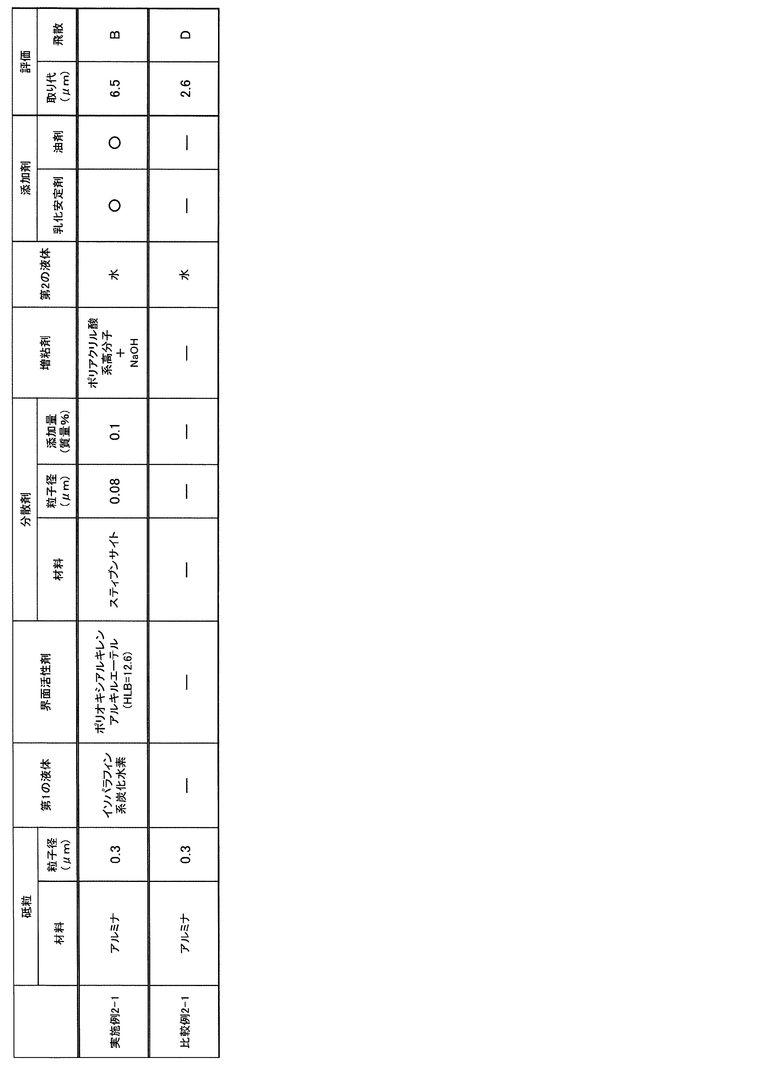
[第3実施例]
本発明を、以下の実施例3-1および比較例3-1を用いてさらに詳細に説明する。ただし、本発明の技術的範囲が以下の実施例のみに制限されるわけではない。
第3実施例は、ダブルアクションポリッシャに装着する研磨パッドを、C硬度が23である発泡ポリウレタンパッド(図3を参照)にした以外は、第1実施例と研磨用組成物の調製方法や研磨条件、あるいは各評価の基準等において同一である。よって、ここでは、第3実施例における研磨用組成物の調製方法、研磨条件や各評価の基準等については説明を省略する。
ただし、実施例3-1の研磨用組成物としては、実施例1-2の研磨用組成物と同一のものを使用した。また、比較例3-1の研磨用組成物としては、比較例1-1の研磨用組成物と同一のものを使用した。
本発明を、以下の実施例3-1および比較例3-1を用いてさらに詳細に説明する。ただし、本発明の技術的範囲が以下の実施例のみに制限されるわけではない。
第3実施例は、ダブルアクションポリッシャに装着する研磨パッドを、C硬度が23である発泡ポリウレタンパッド(図3を参照)にした以外は、第1実施例と研磨用組成物の調製方法や研磨条件、あるいは各評価の基準等において同一である。よって、ここでは、第3実施例における研磨用組成物の調製方法、研磨条件や各評価の基準等については説明を省略する。
ただし、実施例3-1の研磨用組成物としては、実施例1-2の研磨用組成物と同一のものを使用した。また、比較例3-1の研磨用組成物としては、比較例1-1の研磨用組成物と同一のものを使用した。
(比較)
層状ケイ酸塩化合物等を含む研磨用組成物と層状ケイ酸塩化合物等を含まない研磨用組成物とについて研磨の評価および飛散の評価をそれぞれで行った。評価結果を下記表3に示す。
層状ケイ酸塩化合物等を含む研磨用組成物と層状ケイ酸塩化合物等を含まない研磨用組成物とについて研磨の評価および飛散の評価をそれぞれで行った。評価結果を下記表3に示す。

[第4実施例]
本発明を、以下の実施例4-1~4-2および比較例4-1を用いてさらに詳細に説明する。ただし、本発明の技術的範囲が以下の実施例のみに制限されるわけではない。
(研磨用組成物)
実施例4-1の研磨用組成物としては、実施例1-2の研磨用組成物と同一のものを使用した。また、実施例4-2の研磨用組成物としては、実施例1-7の研磨用組成物と同一のものを使用した。また、比較例4-1の研磨用組成物としては、比較例1-1の研磨用組成物と同一のものを使用した。
本発明を、以下の実施例4-1~4-2および比較例4-1を用いてさらに詳細に説明する。ただし、本発明の技術的範囲が以下の実施例のみに制限されるわけではない。
(研磨用組成物)
実施例4-1の研磨用組成物としては、実施例1-2の研磨用組成物と同一のものを使用した。また、実施例4-2の研磨用組成物としては、実施例1-7の研磨用組成物と同一のものを使用した。また、比較例4-1の研磨用組成物としては、比較例1-1の研磨用組成物と同一のものを使用した。
(研磨の評価)
実施例4-1~4-2および比較例4-1の研磨用組成物を用いて、下記の研磨条件で研磨し、前面解消性および飛散を評価した。
実施例4-1~4-2および比較例4-1の研磨用組成物を用いて、下記の研磨条件で研磨し、前面解消性および飛散を評価した。
<研磨条件>
研磨に使用した研磨装置は、ハンドポリッシャである。このハンドポリッシャには研磨面に格子溝を備えた研磨パッド(図3を参照)が装着されており、ハンドポリッシャに付与された押し付け力で研磨パッドの研磨面を研磨対象物の被研磨面に押し付け、被研磨面上に研磨用組成物を供給しながら、ハンドポリッシャを回転することにより研磨を行った。なお、具体的な研磨条件は、以下の通りである。
ポリッシャの回転数:650rpm
研磨用組成物の流量:2ml/15sec
研磨時間:1分間
研磨圧力、研磨速度、研磨時間等の研磨条件は、全ての試験について同一とした。なおハンドポリッシャに装着する研磨パッドは、研磨面に格子溝を備えた研磨パッド以外に、例えば本実施形態で説明した図2、4~17に記載の研磨パッドであってもよい。使用した研磨パッドは発泡ポリウレタンバフであり、C硬度17である。
使用した研磨対象物は、アルミニウム合金A6061である。つまり、被研磨面は、合金からなる面である。
研磨に使用した研磨装置は、ハンドポリッシャである。このハンドポリッシャには研磨面に格子溝を備えた研磨パッド(図3を参照)が装着されており、ハンドポリッシャに付与された押し付け力で研磨パッドの研磨面を研磨対象物の被研磨面に押し付け、被研磨面上に研磨用組成物を供給しながら、ハンドポリッシャを回転することにより研磨を行った。なお、具体的な研磨条件は、以下の通りである。
ポリッシャの回転数:650rpm
研磨用組成物の流量:2ml/15sec
研磨時間:1分間
研磨圧力、研磨速度、研磨時間等の研磨条件は、全ての試験について同一とした。なおハンドポリッシャに装着する研磨パッドは、研磨面に格子溝を備えた研磨パッド以外に、例えば本実施形態で説明した図2、4~17に記載の研磨パッドであってもよい。使用した研磨パッドは発泡ポリウレタンバフであり、C硬度17である。
使用した研磨対象物は、アルミニウム合金A6061である。つまり、被研磨面は、合金からなる面である。
(前面解消性の評価)
非接触表面形状測定機(レーザー顕微鏡、VK-X200、株式会社キーエンス製)を用いて、倍率200倍(測定領域1350×1012μm)で測定したRv(最大谷深さ)の値が2μmである研磨キズを備えたアルミニウム合金A6061の前面を上記研磨条件で研磨した。
そして、1分以内に上記Rvの値が2μmを下回った場合、前面解消性は合格「A」とした。一方、1分後も上記Rvの値が2μmを下回らなかった場合、前面解消性は不合格「D」とした。
非接触表面形状測定機(レーザー顕微鏡、VK-X200、株式会社キーエンス製)を用いて、倍率200倍(測定領域1350×1012μm)で測定したRv(最大谷深さ)の値が2μmである研磨キズを備えたアルミニウム合金A6061の前面を上記研磨条件で研磨した。
そして、1分以内に上記Rvの値が2μmを下回った場合、前面解消性は合格「A」とした。一方、1分後も上記Rvの値が2μmを下回らなかった場合、前面解消性は不合格「D」とした。
(飛散の評価)
飛散の評価については、第1実施例の評価と同一である。よって、ここでは、その説明を省略する。
飛散の評価については、第1実施例の評価と同一である。よって、ここでは、その説明を省略する。
(比較)
層状ケイ酸塩化合物等を含む研磨用組成物と層状ケイ酸塩化合物等を含まない研磨用組成物とについて研磨の評価および飛散の評価をそれぞれで行った。評価結果を下記表4に示す。
層状ケイ酸塩化合物等を含む研磨用組成物と層状ケイ酸塩化合物等を含まない研磨用組成物とについて研磨の評価および飛散の評価をそれぞれで行った。評価結果を下記表4に示す。

[第5実施例]
本発明を、以下の実施例5-1および比較例5-1を用いてさらに詳細に説明する。ただし、本発明の技術的範囲が以下の実施例のみに制限されるわけではない。
(研磨用組成物)
実施例5-1の研磨用組成物としては、実施例1-2の研磨用組成物と同一のものを使用した。また、比較例5-1の研磨用組成物としては、比較例1-1の研磨用組成物と同一のものを使用した。
本発明を、以下の実施例5-1および比較例5-1を用いてさらに詳細に説明する。ただし、本発明の技術的範囲が以下の実施例のみに制限されるわけではない。
(研磨用組成物)
実施例5-1の研磨用組成物としては、実施例1-2の研磨用組成物と同一のものを使用した。また、比較例5-1の研磨用組成物としては、比較例1-1の研磨用組成物と同一のものを使用した。
(研磨の評価)
実施例5-1および比較例5-1の研磨用組成物を用いて、第4実施例の研磨条件とポリッシャの回転数や研磨時間等が同一の研磨条件で研磨し、前面解消性および飛散を評価した。
なお、研磨対象物は、鉄合金SUS304である。つまり、被研磨面は、合金からなる面である。
実施例5-1および比較例5-1の研磨用組成物を用いて、第4実施例の研磨条件とポリッシャの回転数や研磨時間等が同一の研磨条件で研磨し、前面解消性および飛散を評価した。
なお、研磨対象物は、鉄合金SUS304である。つまり、被研磨面は、合金からなる面である。
(前面解消性の評価)
非接触表面形状測定機(レーザー顕微鏡、VK-X200、株式会社キーエンス製)を用いて、倍率200倍(測定領域1350×1012μm)で測定したRv(最大谷深さ)の値が1μmである研磨キズを備えたSUS304の前面を上記研磨条件で研磨した。
そして、1分以内に上記Rvの値が1μmを下回った場合、前面解消性は合格「A」とした。一方、1分後も上記Rvの値が1μmを下回らなかった場合、前面解消性は不合格「D」とした。
非接触表面形状測定機(レーザー顕微鏡、VK-X200、株式会社キーエンス製)を用いて、倍率200倍(測定領域1350×1012μm)で測定したRv(最大谷深さ)の値が1μmである研磨キズを備えたSUS304の前面を上記研磨条件で研磨した。
そして、1分以内に上記Rvの値が1μmを下回った場合、前面解消性は合格「A」とした。一方、1分後も上記Rvの値が1μmを下回らなかった場合、前面解消性は不合格「D」とした。
(飛散の評価)
飛散の評価については、第1実施例の評価と同一である。よって、ここでは、その説明を省略する。
飛散の評価については、第1実施例の評価と同一である。よって、ここでは、その説明を省略する。
(比較)
層状ケイ酸塩化合物等を含む研磨用組成物と層状ケイ酸塩化合物等を含まない研磨用組成物とについて研磨の評価および飛散の評価をそれぞれで行った。評価結果を下記表5に示す。
層状ケイ酸塩化合物等を含む研磨用組成物と層状ケイ酸塩化合物等を含まない研磨用組成物とについて研磨の評価および飛散の評価をそれぞれで行った。評価結果を下記表5に示す。
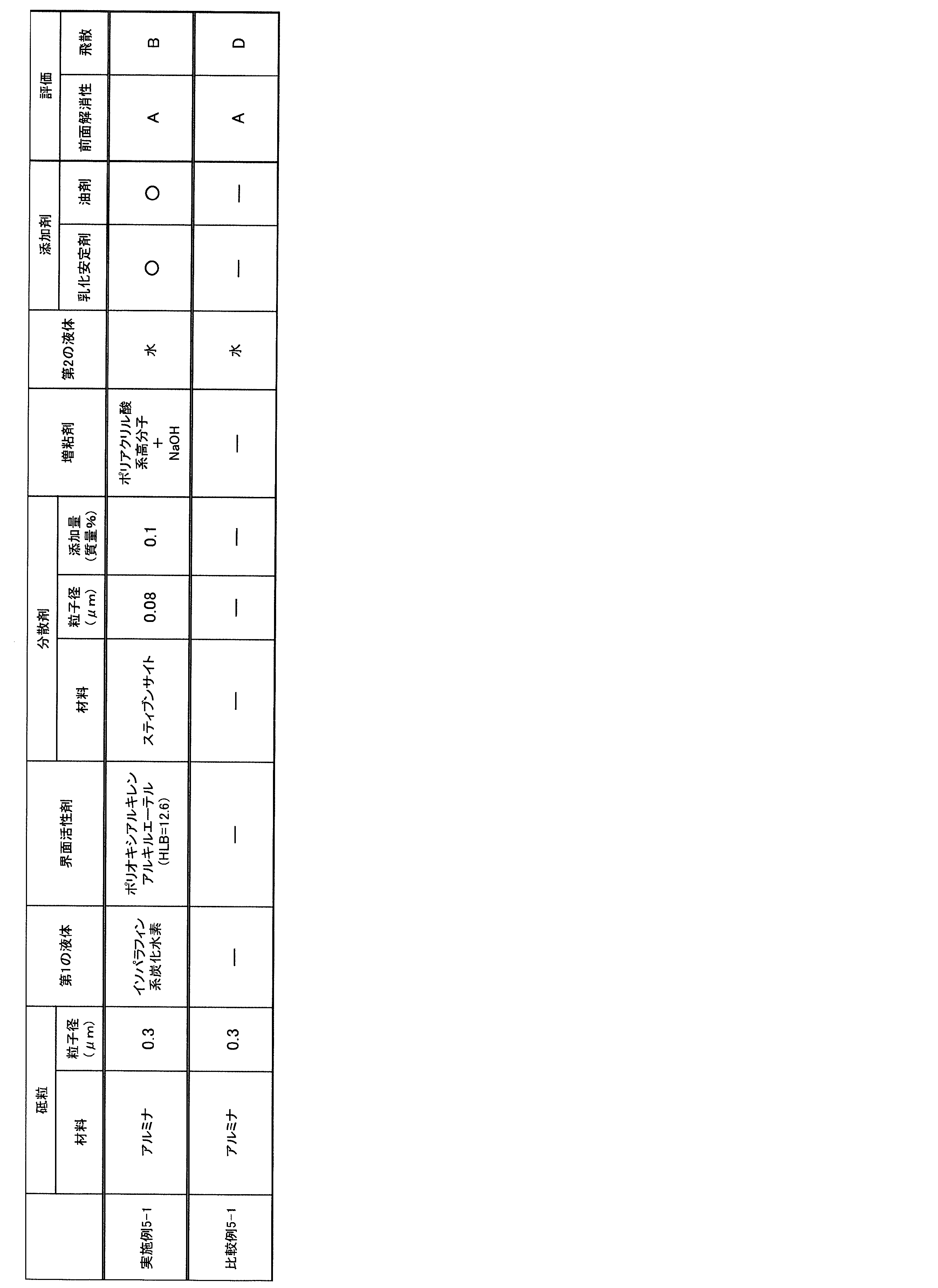
上記表1~表3から明らかなように、層状ケイ酸塩化合物を含むエマルションタイプの研磨用組成物を用いた場合(実施例1-1~1-19、実施例2-1、実施例3-1)、研磨性能および飛散防止性能において良好な結果が得られた。特に、層状ケイ酸塩化合物を添加しておらず、エマルションタイプでもない比較例(比較例1-1~1-4、1-12、1-13、比較例2-1、比較例3-1)と比べて、研磨用組成物の飛散防止性能が向上することがわかった。また、層状ケイ酸塩化合物を添加していない比較例(比較例1-6、1-7、1-9~1-11)と比べて、取り代等の研磨性能が向上することがわかった。また、増粘剤を添加していない比較例(比較例1-5、1-8)と比べて、飛散防止性能が向上することがわかった。
また、上記表4~表5から明らかなように、層状ケイ酸塩化合物を含むエマルションタイプの研磨用組成物を用いた場合(実施例4-1~4-2、実施例5-1)、層状ケイ酸塩化合物を添加しておらず、エマルションタイプでもない比較例(比較例4-1、比較例5-1)と比べて、前面解消性は維持しつつ、飛散防止性能が良好となるという結果が得られた。
10 研磨パッド
30 研磨面
31 第1溝
32 第2溝
33 第3溝
34 第4溝
35 第5溝
36 第6溝
40 硬質の層
40a 切り欠き
40A 花弁状領域
40Aa 分割端
40B 花弁状領域
40Ba Ba
40c 線状溝
40C 花弁状領域
50 軟質の層
50a 凹部
51 支持面
60 止水層
90 研磨対象物
102 ロボットアーム
104 研磨工具
105 押圧力検出部
107 コントローラ
30 研磨面
31 第1溝
32 第2溝
33 第3溝
34 第4溝
35 第5溝
36 第6溝
40 硬質の層
40a 切り欠き
40A 花弁状領域
40Aa 分割端
40B 花弁状領域
40Ba Ba
40c 線状溝
40C 花弁状領域
50 軟質の層
50a 凹部
51 支持面
60 止水層
90 研磨対象物
102 ロボットアーム
104 研磨工具
105 押圧力検出部
107 コントローラ
Claims (11)
- 砥粒と、疎水性を有する第1の液体と、界面活性剤と、層状ケイ酸塩化合物と、増粘剤と、親水性を有する第2の液体とを含む、研磨用組成物。
- 添加剤として、油剤、および乳化安定剤の少なくとも一種をさらに含む、請求項1に記載の研磨用組成物。
- 前記層状ケイ酸塩化合物の平均一次粒子径が15μm以下である、請求項1または2に記載の研磨用組成物。
- 前記層状ケイ酸塩化合物の添加量が0.001質量%以上10質量%以下である、請求項1~3のいずれか1項に記載の研磨用組成物。
- 前記砥粒が酸化アルミニウム、炭化ケイ素、二酸化ケイ素、酸化セリウム、および酸化ジルコニウムの少なくとも一種を含む、請求項1~4のいずれか1項に記載の研磨用組成物。
- 前記砥粒の平均二次粒子径が0.05μm以上50μm以下である、請求項1~5のいずれか1項に記載の研磨用組成物。
- 前記第1の液体(L1)と、前記第2の液体(L2)との体積比(L1/L2)が1未満である、請求項1~6のいずれか1項に記載の研磨用組成物。
- 前記第1の液体(L1)と、前記第2の液体(L2)との体積比(L1/L2)が1以上である、請求項1~6のいずれか1項に記載の研磨用組成物。
- 請求項1~8のいずれか1項に記載の研磨用組成物を製造する方法であって、
前記砥粒と、前記第1の液体と、前記界面活性剤と、前記層状ケイ酸塩化合物と、増粘剤と、前記第2の液体と、を混合する工程を有する、研磨用組成物の製造方法。 - 請求項1~8のいずれか1項に記載の研磨用組成物を用いて研磨対象物を研磨する、研磨方法。
- 前記研磨対象物は、樹脂材料、合金材料、およびガラス材料からなる群より選択される少なくとも1種を含む、請求項10に記載の研磨方法。
Priority Applications (2)
| Application Number | Priority Date | Filing Date | Title |
|---|---|---|---|
| JP2019545162A JPWO2019066014A1 (ja) | 2017-09-29 | 2018-09-28 | 研磨用組成物、研磨用組成物の製造方法、および研磨方法 |
| TW108105052A TW201938748A (zh) | 2018-03-16 | 2019-02-15 | 研磨用組成物、研磨用組成物之製造方法及研磨方法 |
Applications Claiming Priority (4)
| Application Number | Priority Date | Filing Date | Title |
|---|---|---|---|
| JP2017-191348 | 2017-09-29 | ||
| JP2017191348 | 2017-09-29 | ||
| JP2018-048888 | 2018-03-16 | ||
| JP2018048888 | 2018-03-16 |
Publications (1)
| Publication Number | Publication Date |
|---|---|
| WO2019066014A1 true WO2019066014A1 (ja) | 2019-04-04 |
Family
ID=65903076
Family Applications (1)
| Application Number | Title | Priority Date | Filing Date |
|---|---|---|---|
| PCT/JP2018/036406 Ceased WO2019066014A1 (ja) | 2017-09-29 | 2018-09-28 | 研磨用組成物、研磨用組成物の製造方法、および研磨方法 |
Country Status (2)
| Country | Link |
|---|---|
| JP (1) | JPWO2019066014A1 (ja) |
| WO (1) | WO2019066014A1 (ja) |
Cited By (5)
| Publication number | Priority date | Publication date | Assignee | Title |
|---|---|---|---|---|
| US20210332264A1 (en) * | 2020-04-23 | 2021-10-28 | Fujimi Corporation | Novel polishing vehicles and compositions with tunable viscosity |
| WO2022210744A1 (ja) | 2021-03-31 | 2022-10-06 | 株式会社フジミインコーポレーテッド | 研磨用組成物、研磨用組成物の製造方法および研磨方法 |
| CN115519438A (zh) * | 2022-09-26 | 2022-12-27 | 湖南银山竹业有限公司 | 一种竹制餐具成型机 |
| WO2024128192A1 (ja) * | 2022-12-14 | 2024-06-20 | ニッタ・デュポン株式会社 | 研磨組成物 |
| WO2025105368A1 (ja) * | 2023-11-17 | 2025-05-22 | 株式会社フジミインコーポレーテッド | 研磨用組成物および研磨方法 |
Families Citing this family (2)
| Publication number | Priority date | Publication date | Assignee | Title |
|---|---|---|---|---|
| CN114227529B (zh) * | 2021-12-06 | 2023-09-15 | 河南联合精密材料股份有限公司 | 一种蓝宝石晶片减薄加工用树脂研磨垫及其制备方法 |
| CN114260815A (zh) * | 2021-12-31 | 2022-04-01 | 华侨大学 | 基于机器人的高世代线玻璃基板抛光系统及其抛光方法 |
Citations (4)
| Publication number | Priority date | Publication date | Assignee | Title |
|---|---|---|---|---|
| JP2000282011A (ja) * | 1999-03-30 | 2000-10-10 | Soft 99 Corporation:Kk | バフ研摩用組成物 |
| JP2004359831A (ja) * | 2003-06-05 | 2004-12-24 | Ishihara Chem Co Ltd | 研磨組成物 |
| JP2008255232A (ja) * | 2007-04-05 | 2008-10-23 | Soft99 Corporation | 研磨剤組成物 |
| JP6099067B1 (ja) * | 2016-04-26 | 2017-03-22 | 株式会社フジミインコーポレーテッド | 研磨用組成物 |
-
2018
- 2018-09-28 WO PCT/JP2018/036406 patent/WO2019066014A1/ja not_active Ceased
- 2018-09-28 JP JP2019545162A patent/JPWO2019066014A1/ja active Pending
Patent Citations (4)
| Publication number | Priority date | Publication date | Assignee | Title |
|---|---|---|---|---|
| JP2000282011A (ja) * | 1999-03-30 | 2000-10-10 | Soft 99 Corporation:Kk | バフ研摩用組成物 |
| JP2004359831A (ja) * | 2003-06-05 | 2004-12-24 | Ishihara Chem Co Ltd | 研磨組成物 |
| JP2008255232A (ja) * | 2007-04-05 | 2008-10-23 | Soft99 Corporation | 研磨剤組成物 |
| JP6099067B1 (ja) * | 2016-04-26 | 2017-03-22 | 株式会社フジミインコーポレーテッド | 研磨用組成物 |
Cited By (5)
| Publication number | Priority date | Publication date | Assignee | Title |
|---|---|---|---|---|
| US20210332264A1 (en) * | 2020-04-23 | 2021-10-28 | Fujimi Corporation | Novel polishing vehicles and compositions with tunable viscosity |
| WO2022210744A1 (ja) | 2021-03-31 | 2022-10-06 | 株式会社フジミインコーポレーテッド | 研磨用組成物、研磨用組成物の製造方法および研磨方法 |
| CN115519438A (zh) * | 2022-09-26 | 2022-12-27 | 湖南银山竹业有限公司 | 一种竹制餐具成型机 |
| WO2024128192A1 (ja) * | 2022-12-14 | 2024-06-20 | ニッタ・デュポン株式会社 | 研磨組成物 |
| WO2025105368A1 (ja) * | 2023-11-17 | 2025-05-22 | 株式会社フジミインコーポレーテッド | 研磨用組成物および研磨方法 |
Also Published As
| Publication number | Publication date |
|---|---|
| JPWO2019066014A1 (ja) | 2020-11-26 |
Similar Documents
| Publication | Publication Date | Title |
|---|---|---|
| WO2019066014A1 (ja) | 研磨用組成物、研磨用組成物の製造方法、および研磨方法 | |
| JP5935865B2 (ja) | 炭化ケイ素単結晶基板の製造方法 | |
| US8398878B2 (en) | Methods for producing and processing semiconductor wafers | |
| JP6099067B1 (ja) | 研磨用組成物 | |
| JP7825609B2 (ja) | 研磨用組成物、研磨用組成物の製造方法および研磨方法 | |
| TWI481680B (zh) | 用於鎳-磷記憶碟之拋光組合物 | |
| TWI619805B (zh) | 用於硬脆材料之研磨用組成物、硬脆材料基板之研磨方法及製造方法 | |
| US20090045410A1 (en) | GaN SUBSTRATE AND SEMICONDUCTOR DEVICE PREPARED BY USING METHOD AND APPARATUS OF POLISHING GaN SUBSTRATE | |
| TW201313885A (zh) | 研磨劑及研磨方法 | |
| TW201101378A (en) | Method for polishing the edge of a semiconductor wafer | |
| CN104416450A (zh) | 用于抛光蓝宝石表面的化学机械抛光组合物及其使用方法 | |
| TWI433903B (zh) | 用於鎳-磷記憶碟之拋光組合物 | |
| KR20150120980A (ko) | 연마용 조성물 | |
| JP7420728B2 (ja) | 研磨パッド、及びそれを用いた研磨方法 | |
| TW201938748A (zh) | 研磨用組成物、研磨用組成物之製造方法及研磨方法 | |
| JPWO2020054823A1 (ja) | 研磨パッド、研磨工具、及び研磨方法 | |
| JP5024305B2 (ja) | GaN基板の研磨方法 | |
| TWI922648B (zh) | 研磨用組成物、研磨用組成物之製造方法及研磨方法 | |
| US20240131654A1 (en) | Polishing pad and polishing method | |
| JP2025082408A (ja) | 研磨用組成物および研磨方法 | |
| WO2025105368A1 (ja) | 研磨用組成物および研磨方法 | |
| JP2022156010A (ja) | 研磨装置及び研磨方法 | |
| JP2026055268A (ja) | 研磨用組成物、研磨用組成物の製造方法および研磨方法 | |
| JP5195966B2 (ja) | GaN基板の研磨方法 |
Legal Events
| Date | Code | Title | Description |
|---|---|---|---|
| 121 | Ep: the epo has been informed by wipo that ep was designated in this application |
Ref document number: 18863088 Country of ref document: EP Kind code of ref document: A1 |
|
| ENP | Entry into the national phase |
Ref document number: 2019545162 Country of ref document: JP Kind code of ref document: A |
|
| NENP | Non-entry into the national phase |
Ref country code: DE |
|
| 122 | Ep: pct application non-entry in european phase |
Ref document number: 18863088 Country of ref document: EP Kind code of ref document: A1 |