WO2019065616A1 - 操作画像表示装置及び操作装置 - Google Patents
操作画像表示装置及び操作装置 Download PDFInfo
- Publication number
- WO2019065616A1 WO2019065616A1 PCT/JP2018/035411 JP2018035411W WO2019065616A1 WO 2019065616 A1 WO2019065616 A1 WO 2019065616A1 JP 2018035411 W JP2018035411 W JP 2018035411W WO 2019065616 A1 WO2019065616 A1 WO 2019065616A1
- Authority
- WO
- WIPO (PCT)
- Prior art keywords
- display
- display mode
- image
- radial menu
- control unit
- Prior art date
- Legal status (The legal status is an assumption and is not a legal conclusion. Google has not performed a legal analysis and makes no representation as to the accuracy of the status listed.)
- Ceased
Links
Images

Classifications
-
- B—PERFORMING OPERATIONS; TRANSPORTING
- B60—VEHICLES IN GENERAL
- B60K—ARRANGEMENT OR MOUNTING OF PROPULSION UNITS OR OF TRANSMISSIONS IN VEHICLES; ARRANGEMENT OR MOUNTING OF PLURAL DIVERSE PRIME-MOVERS IN VEHICLES; AUXILIARY DRIVES FOR VEHICLES; INSTRUMENTATION OR DASHBOARDS FOR VEHICLES; ARRANGEMENTS IN CONNECTION WITH COOLING, AIR INTAKE, GAS EXHAUST OR FUEL SUPPLY OF PROPULSION UNITS IN VEHICLES
- B60K35/00—Instruments specially adapted for vehicles; Arrangement of instruments in or on vehicles
- B60K35/80—Arrangements for controlling instruments
- B60K35/81—Arrangements for controlling instruments for controlling displays
-
- B—PERFORMING OPERATIONS; TRANSPORTING
- B60—VEHICLES IN GENERAL
- B60K—ARRANGEMENT OR MOUNTING OF PROPULSION UNITS OR OF TRANSMISSIONS IN VEHICLES; ARRANGEMENT OR MOUNTING OF PLURAL DIVERSE PRIME-MOVERS IN VEHICLES; AUXILIARY DRIVES FOR VEHICLES; INSTRUMENTATION OR DASHBOARDS FOR VEHICLES; ARRANGEMENTS IN CONNECTION WITH COOLING, AIR INTAKE, GAS EXHAUST OR FUEL SUPPLY OF PROPULSION UNITS IN VEHICLES
- B60K35/00—Instruments specially adapted for vehicles; Arrangement of instruments in or on vehicles
- B60K35/10—Input arrangements, i.e. from user to vehicle, associated with vehicle functions or specially adapted therefor
-
- B—PERFORMING OPERATIONS; TRANSPORTING
- B60—VEHICLES IN GENERAL
- B60K—ARRANGEMENT OR MOUNTING OF PROPULSION UNITS OR OF TRANSMISSIONS IN VEHICLES; ARRANGEMENT OR MOUNTING OF PLURAL DIVERSE PRIME-MOVERS IN VEHICLES; AUXILIARY DRIVES FOR VEHICLES; INSTRUMENTATION OR DASHBOARDS FOR VEHICLES; ARRANGEMENTS IN CONNECTION WITH COOLING, AIR INTAKE, GAS EXHAUST OR FUEL SUPPLY OF PROPULSION UNITS IN VEHICLES
- B60K35/00—Instruments specially adapted for vehicles; Arrangement of instruments in or on vehicles
- B60K35/20—Output arrangements, i.e. from vehicle to user, associated with vehicle functions or specially adapted therefor
- B60K35/21—Output arrangements, i.e. from vehicle to user, associated with vehicle functions or specially adapted therefor using visual output, e.g. blinking lights or matrix displays
- B60K35/22—Display screens
-
- B—PERFORMING OPERATIONS; TRANSPORTING
- B60—VEHICLES IN GENERAL
- B60R—VEHICLES, VEHICLE FITTINGS, OR VEHICLE PARTS, NOT OTHERWISE PROVIDED FOR
- B60R16/00—Electric or fluid circuits specially adapted for vehicles and not otherwise provided for; Arrangement of elements of electric or fluid circuits specially adapted for vehicles and not otherwise provided for
- B60R16/02—Electric or fluid circuits specially adapted for vehicles and not otherwise provided for; Arrangement of elements of electric or fluid circuits specially adapted for vehicles and not otherwise provided for electric constitutive elements
-
- G—PHYSICS
- G09—EDUCATION; CRYPTOGRAPHY; DISPLAY; ADVERTISING; SEALS
- G09G—ARRANGEMENTS OR CIRCUITS FOR CONTROL OF INDICATING DEVICES USING STATIC MEANS TO PRESENT VARIABLE INFORMATION
- G09G5/00—Control arrangements or circuits for visual indicators common to cathode-ray tube indicators and other visual indicators
-
- G—PHYSICS
- G09—EDUCATION; CRYPTOGRAPHY; DISPLAY; ADVERTISING; SEALS
- G09G—ARRANGEMENTS OR CIRCUITS FOR CONTROL OF INDICATING DEVICES USING STATIC MEANS TO PRESENT VARIABLE INFORMATION
- G09G5/00—Control arrangements or circuits for visual indicators common to cathode-ray tube indicators and other visual indicators
- G09G5/36—Control arrangements or circuits for visual indicators common to cathode-ray tube indicators and other visual indicators characterised by the display of a graphic pattern, e.g. using an all-points-addressable [APA] memory
Definitions
- the present invention relates to an operation image display device used in a vehicle and displaying a selected image, and an operation device performing an operation while visually recognizing the operation image.
- the conventional operation device arranges a plurality of icon images at positions radially separated from the center, is provided on the steering wheel, and contacts a user centered on a predetermined center point.
- One of the plurality of icon images can be selected in accordance with the position to be detected (the direction in which the user touches the center point).
- An icon image group (selected image group) displaying such a plurality of icon images at a position away from the center is also called a radial menu.
- the display area (area to be displayed) becomes large, and there is a possibility that the user may feel bothersome or press the display area of other information.
- the radial menu is displayed on the head-up display device, it may be difficult to visually recognize the real view, and when the radial menu is displayed on the instrument panel, an area for displaying information other than the radial menu There was a possibility that it would be necessary to reduce or lay out the layout.
- the present invention has been made in view of the above problems, and it is an object of the present invention to provide an operation image display device and an operation device capable of improving the degree of freedom of display layout and display blockage by the radial menu. To aim.
- the present invention adopts the following means in order to solve the problems.
- the operation image display apparatus and the operation apparatus according to the present invention can display the radial menu in a first display mode or a second display mode having a larger area than the first display mode, and can display the second display mode.
- the radial menu can be set to a predetermined condition by enlarging the operation range in which at least one selected image of the plurality of selected images displayed in the second display mode is displayed as compared with the case where the first display mode is displayed. Accordingly, even the first display mode having a small area can be displayed, and the display area of the radial menu can be reduced.
- the selectable operation range of at least a part of the selected images is widened, so that an erroneous selected image is hard to be selected, suppressing the decrease in operability. Make it a gist.
- the operation image display apparatus is instructed based on an operation information acquisition unit (40) for acquiring operation information by a user and the operation information acquired from the operation information acquisition unit (40).
- a display control unit (20) configured to display the second display mode (520) having a larger area than the mode (510) or the first display mode (510), and the display control unit (20)
- a ratio (W) of the first selected image (502) of at least a part of the selected images (501) in the orbit is compared with the ratio (W2) in the second display mode (520) First display mode (5 0) increasing towards ratio of (W1) during.
- the display is changed to the first display aspect having a small area according to the situation. This can improve the obstruction of the view by the radial menu or the freedom of the display layout of the display. Further, when changing the radial menu from the second display mode to the first display mode having a smaller area, the ratio of the partial selection image (first selection image) occupying the track of the radial menu is enlarged, and the partial selection image is selected. Delete (second selected image) or / and reduce the ratio. Thereby, even when the radial menu changes to the first display mode having a small area, the ratio of a part of selected images is enlarged, and an operation to designate a predetermined selected image by the operation unit becomes easy, and operability Can be suppressed.
- the display control unit (20) sets the radial menu (500) to the first display mode (510), and then the predetermined mode is performed. And the second display mode (520) may be changed.
- the first display mode of the radial menu with a small area is changed to the second display mode with a large area, it is difficult to display the radial menu with the large area at first, and the radial It is possible to make it difficult to prevent the view from being disturbed by the menu or the degree of freedom of the display layout of the display.
- the operation image display apparatus which is subordinate to the second aspect, further includes a line-of-sight information acquisition unit (50) capable of acquiring line-of-sight information regarding the user's line of sight, the display control unit (20) It may be determined that the predetermined condition is satisfied at least when the user views the radial menu for a predetermined time or more.
- a line-of-sight information acquisition unit 50
- the display control unit (20) It may be determined that the predetermined condition is satisfied at least when the user views the radial menu for a predetermined time or more.
- the display control unit (20) transmits the first display mode (510) to the second display mode (520).
- the selected image (501) instructed based on the operation information in the first display mode (510) is instructed after changing to the second display mode (520).
- the position of the selected image (501) on the radial menu (500) may be changed or / and the ratio may be changed.
- the ratio of some selected images is reduced.
- the ratio of occupying the trajectory may be reduced and thus not selected.
- the selection image which has been extended at 1 ° to 90 ° with respect to the center of the radial menu in the first display mode is displayed second
- the operation information obtained from the operation information obtaining unit is 60 °
- an instruction is given in the first display mode
- the selected image instructed in the second display mode differ from each other. That is, even if the operation information is constant, a change in the display mode causes a problem that the instructed selected image changes.
- the selected image which is instructed based on the operation information in the first display mode is instructed even after the change to the second display mode. Change the position on the radial menu or / and change the ratio.
- the selected image that has been selected is extended to 46 ° to 90 ° (from 1 ° to 45 ° originally) Move the one that was intended to extend into the) or / and extend it by 1 ° to 70 ° (to enlarge what was originally intended to extend from 1 ° to 45 °) Can be prevented.
- the display control unit (20) is configured to execute the first display mode (510) from the second display mode (520). Such that the selected image (501) instructed based on the operation information in the second display mode (520) is instructed after changing to the first display mode (510), The position of the selected image (501) on the radial menu (500) may be changed or / and the ratio may be changed.
- the selection image extending 46 ° to 90 ° with respect to the center of the radial menu in the second display mode is the first display
- the operation information obtained from the operation information obtaining unit is 60 °
- an instruction is given in the second display mode
- the selected image instructed in the first display mode differ from each other.
- the selected image instructed based on the operation information in the second display mode is instructed even after the change to the first display mode. Change the position on the radial menu or / and change the ratio.
- the selected image that has been selected is extended from 1 ° to 90 ° (originally from 91 ° to 180 ° To move the ones that were intended to extend into the) or / and to extend 50 ° to 180 ° (to enlarge what was originally intended to extend 91 ° to 180 °) Can be prevented.
- the display control unit (20) transmits the first display mode (510) to the second display mode (520).
- the ratio (W1) of the first selected image (502) specified based on the operation information may be maintained. This also achieves the same effect as that of the third aspect.
- the display control unit (20) increases the speed of reducing the display area of the radial menu (500). It may be faster.
- the radial menu can be made small quickly, and the obstruction of the view by the radial menu or the restriction of the display layout of the display can be quickly eliminated.
- the radial menu is enlarged when the operation is performed more intensively, but the user gazes even after the display mode changes, by making the speed at the time of expansion at least a visible deformation speed. It is difficult to lose sight of the target (selected image), and operability can be improved.
- the display control unit (20) has an area of the radial menu (500) larger than that of the first display mode (510).
- the third display mode (500a) can be deformed and displayed, and the speed at which the third display mode (500a) is deformed to the first display mode (510) corresponds to the first display mode (510).
- an operation device according to any one of the first to eighth aspects, wherein the operation image display device (100) and the selected image (501) displayed on the display unit (10) are indicated. And an operation unit (200) for detecting operation information. Thereby, while visually recognizing the radial menu (selected image group) displayed on the operation image display device, it is possible to designate a desired selected image.
- the operation unit may output not only the instruction of the selected image but also the operation information related to selection (determination).
- the operation control device further includes a sub operation unit (300) for detecting a user's line of sight or / and a user's voice, and the display control unit (20)
- the selection image (501) specified based on the operation information acquired from the operation unit (200) may be selected based on the sub operation information acquired from the sub operation unit (300).
- the operation unit may instruct the desired selected image, and the finally instructed selected image may be selected (decided) based on the line of sight or the voice of the user detected from the sub operation unit.
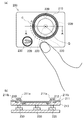
- FIG. 2A is a front view
- FIG. 2B is a cross-sectional view taken along the line AA in FIG. 2A.
- FIG. 1 is a view showing the configuration of an embodiment of the operating device of the present invention.
- the controller device of the present embodiment includes an operation image display device 100, an operation unit 200, and a sub operation unit 300, is connected to the external device 400, and operates the external device 400 by an operation performed by the controller device, The display content of the display 10 is changed based on the information from the external device 400.
- the operation image display device 100 of the present embodiment is mounted on the vehicle 1.
- the vehicle 1 has a windshield 2 and a steering wheel 3.
- the operation image display device 100 displays the radial menu 500, and the operation unit 200 operated by the user, the gaze detection unit 301 detecting the gaze of the user, and the voice detection detecting the voice instruction of the user
- the sub operation unit 300 including the unit 302 and the external device 400 including the vehicle ECU 401, the navigation ECU 402, the audio ECU 403, the air conditioning ECU 404, the external communication unit 405, etc. are connected, and the operation unit 200, the sub operation unit 300, and the external Based on the information input from the device 400, the display mode of the radial menu 500 is changed.
- the operation image display apparatus 100 includes the display 10 for displaying the radial menu 500 which is the virtual image V in the display area 101, the display control unit 20 for controlling the display 10, and the display 10 from the external device 400.
- Operation information for acquiring the user's “operation information” from the input / output interface 30 for acquiring “external device information” which is the source of the selected image 501 of the radial menu 500 displayed by the user, and the operation unit 200 provided on the steering wheel 3
- the sub operation information acquisition unit 50 may be omitted.
- the display 10 projects a display light toward the windshield 2 of the vehicle 1 to display a virtual image V (including a radial menu 500) superimposed on the real view through the windshield 2.
- the display 10 changes the display mode of the virtual image V (radial menu 500) based on control by the display control unit 20.
- the radial menu 500 may not be displayed as the virtual image V, but may be displayed as a real image.
- the display 10 may be configured of a display panel provided in or on the instrument panel.
- the display control unit 20 acquires external device information from the input / output interface 30, generates a plurality of selected images 501 based on this, and an array stored in advance in a storage unit (not shown) provided in the display control unit 20, or
- the radial menu 500 (see FIGS. 4A and 4B) is constructed by arranging the plurality of selected images 501 in an array determined by the program stored in the storage unit. Note that the display control unit 20 may create the selected image 501 based on the image data stored in the storage unit (not shown), not based on the external device information, and construct the radial menu 500. [Example of external device information]
- the vehicle ECU 401 can output the traveling mode (ECO mode, SPORT mode) of the vehicle 1, the average fuel consumption, the travelable distance (travelable distance), the water temperature, the oil temperature and the like, and the display control unit 20
- the driving mode of the vehicle 1 is shown, and a selected image 503 capable of changing the driving mode by being selected (see FIG. 4), average fuel consumption, travelable distance (travelable distance), water temperature, oil temperature etc. are displayed in the area
- a selected image 505 (see FIG. 4) or the like capable of displaying detailed information on the additional vehicle 1 by being selected may be displayed in the radial menu 500.
- the navigation ECU 402 information on the direction of the next branch and the distance to the branch, facility information on a recommended passing site located in the vicinity of the route of the vehicle 1, and information such as time lost when passing through this. It is possible to output, the display control unit 20 indicates the direction of the next branch not shown and the distance to the branch based on these, and it is possible to switch on / off of the route guidance in another display area by being selected.
- a selected image (not shown) or facility information on a recommended via point may be displayed, and a selected image (not shown) settable on the via point by being selected may be displayed in the radial menu 500.
- the audio ECU 403 can output information on recommended music and the like, and the display control unit 20 indicates information on recommended music based on this, and the selected image 502 can be played by being selected. (See FIG. 4) may be displayed in the radial menu 500.
- the air conditioning ECU 404 can output information on the current air conditioning state and the like, and the display control unit 20 indicates information on the current air conditioning state based on this, and a new radial capable of changing the air conditioning state by being selected.
- a selection image 502 capable of displaying the menu 500 may be displayed in the radial menu 500.
- the external communication unit 405 can output an incoming state, mail reception information, and the like, and the display control unit 20 indicates that there is an incoming call and an incoming mail based on these, and receives a call by being selected.
- a selection image 502 (see FIG. 4) which can be read or can be read by voice can be displayed.
- FIG. 2 (a) is a front view of the operation unit 200
- FIG. 2 (b) is a cross-sectional view taken along the line AA of FIG. 2 (a).
- the operation unit 200 is disposed on the steering wheel 3 and detects which portion the user's thumb is located (detects the operation position C), thereby instructing a selected image 501 in the radial menu 500 described later.
- An operation position detection unit 210, and a determination operation detection unit 220 provided integrally with the operation position detection unit 210 and performing selection (determination) of the selected image 501 when the operation position detection unit 210 is pressed by a finger;
- a return detection unit 230 for inputting a return when pressed by a finger.
- the operation unit 200 is a touch sensor that detects the position (operation position C) at which the user's thumb or the like touches the operation surface, and as illustrated in FIG. 2B, the surface cover 211, the sensor sheet 212, and the spacer 213, and displayed when the user performs an operation (hereinafter referred to as touch operation) touching the operation surface with a thumb or the like (hereinafter referred to as a touch operation) or an operation to trace a predetermined trajectory (hereinafter referred to as a gesture operation).
- touch operation an operation
- a touch operation an operation
- a touch operation an operation
- a touch operation an operation to trace a predetermined trajectory
- the surface cover 211 is formed in a sheet shape from a light-shielding insulating material such as a synthetic resin, and the three-dimensional shape of the concavities and convexities is continuously formed in a circular shape centered on the central point Q, And a relatively flat portion 211b located on the
- the concavo-convex portion 211a has a three-dimensional shape of concavities and convexities formed by providing a large number of convex portions which are long in the direction toward the center point Q and which are short in the circumferential direction along the circumferential track.
- the sensor sheet 212 is disposed in a circle centered on the center point Q at least on the back surface side of the surface cover 211 corresponding to the uneven portion 211 a, detects the operation position C of the user's finger, It is a sensor sheet which outputs a position information signal regarding the operation position C of the user's finger.
- the sensor sheet 212 is integrally formed with the surface cover 211 by drawing, and thus processed into the same shape as the surface cover 211 (see FIG. 2B). By integrally molding in this manner, the surface cover 211 and the sensor sheet 212 become like a single sheet, and the step shape of the concavo-convex portion 211 a is configured by the bent portion of the single sheet become.
- the detection portion of the sensor sheet 212 is disposed corresponding to the step shape of the front cover 211.
- the detection portion of the sensor sheet 212 is disposed corresponding to the step shape of the surface cover 211, even if the operation is performed on the operation surface having the step shape such as the uneven portion 211a, the display is performed.
- the control unit 20 can detect the position of the user's finger.
- the spacer 213 is located on the back surface side of the sensor sheet 212 and is formed in accordance with the shape of the integrally formed surface cover 211 and the sensor sheet 212, and when pressure is applied from the front side of the surface cover 211 by the user's operation Is a member that holds the shape of
- a plurality of determination operation detection units 220 are provided on the back surface side of the operation position detection unit 210, are electrically connected to the display control unit 20, and an operation in which the user presses the operation surface (concave and convex portion 211a) of the operation position detection unit 210.
- the determination operation hereinafter referred to as a pressing operation
- the determination operation detection unit 220 is pressed and transmits a determination signal to the display control unit 20.
- the display control unit 20 selects and determines the selection image 501 in the radial menu 500 based on the determination signal from the determination operation detection unit 220, and switches the display according to the selected selection image 501.
- the return detection unit 230 is a switch separated from the operation position detection unit 210 and the determination operation detection unit 220, and transmits a return signal to the display control unit 20 when the user depresses the operation surface of the return detection unit 230. Based on the return signal from the return detection unit 230, the display control unit 20 returns the display of the radial menu 500 to the display before switching. [Relationship Between Operation Unit 200 and Radial Menu 500]
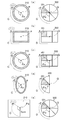
- FIG. 3 is a view showing the relationship between the operation unit 200 and the radial menu 500, and the left view of FIGS. 3 (a), (b), (c), (d) and (e) shows the relationship between the operation unit 200 and FIG. It is an example of the operation position detection part 210 which detects the operation position C, and the right figure shows the mode of the radial menu 500 at the time of being operated by the operation position detection part 210 of the left figure.
- FIG. 3A shows the case where the shape of the trajectory where the operation position detection unit 210 can detect the operation position C and the shape of the trajectory where the selected image 501 is arranged are the same circle.
- the display control unit 20 sets the center point P of the locus at which the relative angle ⁇ q of the designated position D around the center point Q of the locus on which the selected image 501 is arranged can detect the operation position C of the operation position detector 210.
- the pointing position D is moved so as to substantially coincide with the relative angle ⁇ p of the operation position C which is the center.
- FIG. 3B shows the case where the shape of the trajectory where the operation position detection unit 210 can detect the operation position C and the shape of the trajectory where the selected image 501 is arranged are the same rectangle.
- FIG. 3C shows a case where the shape of the locus where the operation position detection unit 210 can detect the operation position C is circular and the shape of the locus where the selected image 501 is arranged is rectangular and is different.
- the display control unit 20 sets the center point P of the locus at which the relative angle ⁇ q of the designated position D around the center point Q of the locus on which the selected image 501 is arranged can detect the operation position C of the operation position detector 210.
- the pointing position D is moved so as to substantially coincide with the relative angle ⁇ p of the operation position C which is the center.
- FIG. 5 when the shape (circle) of the locus capable of detecting the operation position C of the operation position detection unit 210 is different from the shape (rectangle) of the locus on which the selected image 501 is arranged, FIG.
- the designated position D is such that the relative angle ⁇ p corresponds to the relative angle ⁇ p of the operation position C centered on the central point P.
- the shape of the locus where the operation position detection unit 210 can detect the operation position C and the shape of the locus where the selected image 501 is arranged are open figures having a closed figure having no end point or an end point, It is also good.
- a locus capable of detecting the operation position C of the operation position detection unit 210 is an ellipse of a closed figure
- a locus on which the selected image 501 is arranged is a semicircle of an open figure
- the operation position is detected
- the pointing position D moves so as to become a relative angle ⁇ q corresponding to the relative angle ⁇ p of the operating position C centering on the central point P (see FIG. 3 (d)
- the corresponding selected image 501 is selected according to the pressing operation "Push" of the determination operation detection unit 220.
- the operation position detection unit 210 may not be able to detect only the operation position C on the specific trajectory.
- the operation position detection unit 210 is provided to detect the user's operation position C on a two-dimensional surface such as a touch pad, and the user specifies the operation position C on the operation position detection unit 210.
- the display control unit 20 performs a gesture operation on the shape of the trajectory of the center of the trajectory from the operation position C of the operation position detection unit 210 to the operation position C, and the center point Pa of the trajectory and the relative position of the operation position C with respect to the center point Pa.
- the angle ⁇ pa may be determined, and the pointing position D may be controlled to move so as to be the relative angle ⁇ q corresponding to the relative angle ⁇ pa of the operation position C.
- a plurality of decision operation detection units 220 are provided on the back side of the operation position detection unit 210 and electrically connected to the display control unit 20, and the user operates the operation surface of the operation position detection unit 210
- the determination operation detection unit 220 is pressed and the determination signal is transmitted to the display control unit 20.
- the input interface in which the user performs the determination operation and outputs the determination signal If it is, it will not be limited to this.
- the determination operation detection unit 220 may be provided at a position apart from the operation position detection unit 210 which can be operated by the user with the thumb and the operation position detection unit 210 by the thumb.
- the operation position C based on the position of the user's hand is output as a signal by the gesture operation of the operation position detection unit 210, and the user releases the hand from the operation position detection unit 210 at the predetermined operation position C. May be output.
- the determination signal may be output by a double tap operation in which the operation position detection unit 210 is tapped twice quickly at the specific operation position C.
- the display control unit 20 acquires the selected image 501 instructed based on the operation information acquired from the operation unit 200 from the sub operation unit 300 via the sub operation information acquisition unit 50 or the user's gaze The selection may be performed based on the sub-operation information consisting of the sound to be emitted.
- Display mode of radial menu 500
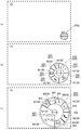
- FIG. 4 is a diagram showing changes in the display mode of the radial menu 500. As shown in FIG. FIG. 4A shows a third display aspect 500a with the smallest area.
- the display control unit 20 usually displays the radial menu 500 in the third display mode 500a as shown in FIG. 1 (a). In the third display mode 500a, the selected image 501 is not displayed, and a specific selection operation is not performed.
- FIG. 4B shows a first display aspect 510 having a larger area than the third display aspect 500a.
- the radial menu 500 of the first display mode 510 is one in which a plurality of selected images 501 are arranged along a trajectory (circular trajectory), and it is possible to select and determine the selected image 501 according to the operation of the operation unit 200. it can.
- FIG. 4C shows a second display aspect 520 having a larger area than the first display aspect 510.
- the radial menu 500 of the second display mode 520 is also the one in which a plurality of selected images 501 are arranged along the trajectory (circular shape) as in the first display mode 510, and the selected image is selected according to the operation of the operation unit 200. 501 can be selected and determined.
- the plurality of selected images 501 have different ratios W of the selected images 501 that occupy the trajectory.
- the ratio W of the selected image 501 along the trajectory occupying the trajectory is set to be approximately equal to the length of the area in which the selected image 501 occupying the entire operation position detection unit 210 of the operation unit 200 can be selected. That is, the longer the ratio W of the selected image 501 is, the wider the area where the selected image 501 can be selected is set on the operation position detection unit 210, so it becomes easier to select the predetermined selected image 501.
- the selection image 501 includes a first selection image 502 in which the length W changes when the display mode changes, and a second selection image 503 in which the length W does not change when the display mode changes. In the example of FIG.
- the first selection image 502 is the selection image 502 for audio, the selection image 502 for air conditioning information, the selection image 502 for telephone and the selection image 502 for mail, and the second selection image 503 is for vehicle mode.
- the selected image 503 is described as "ECO" or "SPORT".
- the ratio W of each selected image 502 decreases (changes from the ratio W1 to the ratio W2),
- the ratio W of each selected image 502 does not change (the ratio W3 remains).
- a new selected image 501 (additional selected image 505) not displayed in the first display mode 510 may be added.
- the ratio W5 of the additional selection image 505 may be set to the maximum of the ratio W of the selection image 501.
- the display control unit 20 may change the radial display 500 to the second display mode 520 when a predetermined condition is satisfied. For example, when the radial menu 500 is in the first display mode 510, the display control unit 20 determines that the predetermined condition is satisfied when the user views the radial menu 500 for a predetermined time or more, and the radial menu 500 is displayed.
- the second display mode 520 may be modified.
- the first display mode of the radial menu with a small area is changed to the second display mode with a large area, it is difficult to display the radial menu with the large area at first, and the radial It is possible to make it difficult to prevent the view from being disturbed by the menu or the degree of freedom of the display layout of the display.
- the conditions for changing the display mode of the radial menu 500 are not limited to the following.
- the display control unit 20 determines that the information acquired from the input / output interface 30 and / or the operation information acquisition unit 40 and / or the sub operation information acquisition unit 50 is a specific type of information, or that the acquired information is a specific condition. If the first condition is satisfied, or if the first condition on the condition that a predetermined combination is established with a plurality of acquired information is satisfied, the radial menu 500 is set to the first display mode 510, and the second condition is If it is established, the radial menu 500 is set to the second display mode 520.
- the second condition is a condition that is more difficult to hold than the first condition, and satisfies the first condition and satisfies the predetermined condition when being in the first display mode 510, or a predetermined condition added to the first condition. It also includes meeting the conditions.
- the first condition includes, for example, at least one of the user touching the operation unit 200, the vehicle 1 stopping, and the line of sight of the user directed to the third display mode 500a.
- the second condition is, for example, that the user touches the operation unit 200 for a predetermined time (for example, 5 seconds) or more, the vehicle 1 stops, and the user touches the operation unit 200, and
- One display mode 510 includes at least one of the fact that it has been directed for a predetermined time (for example, 5 seconds) or more.
- the selected image 501 instructed based on the operation information in the first display mode (510) is the second display mode.
- the position on the radial menu 500 of the selected image 501 may be changed or / and the ratio may be changed as indicated after changing to 520.
- the display control unit 20 changes the second display mode 520 to the first display mode 510
- the selected image 501 instructed based on the operation information in the second display mode 520 is displayed in the first display mode 510.
- the position on the radial menu 500 of the selected image 501 may be changed or / and the ratio may be changed as instructed even after the change.
- the display control unit 20 when changing from the first display mode 510 to the second display mode 520, the display control unit 20 is normally instructed based on the operation information even though the first selection image 502 changes the ratio W.
- the ratio W1 of the first selected image 502 may be maintained.
- the display control unit 20 may set the radial menu 500 so that the speed to reduce the display area is faster than the speed to increase the display area.
- the radial menu 500 can be made small quickly, and the obstruction of the view by the radial menu 500 or the restriction of the display layout of the display can be quickly eliminated.
- the radial menu 500 is enlarged when the operation is performed more intensively, but by setting the speed at the time of expansion to at least a visible deformation speed, the user gazes even after the display mode changes. It is difficult to lose sight of the target (selected image) and operability can be improved.
- the display control unit 20 can change the radial menu 500 into the third display mode 500 a having a smaller area than the first display mode 510 and can display the third display mode 500 a to the first display mode 510.
- the rate of deformation may be faster than the rate of deformation from the first display aspect 510 to the second display aspect 520.
- the present invention is suitable for a head-up display device that causes a viewer to view a virtual image superimposed on the foreground.
- Vehicle 2 Windshield 3: Steering wheel 10: Display 20: Display control unit 30: Input / output interface 40: Operation information acquisition unit 50: Secondary operation information acquisition unit (gaze information acquisition unit, voice information acquisition unit) 100: operation image display device 101: display area 200: operation unit 210: operation position detection unit 300: secondary operation unit 400: external device 500: radial menu 500a: third display mode 501: selected image 502: first selected image 503 : Second selected image 505: additional selected image 510: first display mode 520: second display mode C: operation position D: instructed position P: center point Q: center point V: virtual image W: ratio
Landscapes
- Engineering & Computer Science (AREA)
- Mechanical Engineering (AREA)
- Chemical & Material Sciences (AREA)
- Combustion & Propulsion (AREA)
- Transportation (AREA)
- Physics & Mathematics (AREA)
- Computer Hardware Design (AREA)
- General Physics & Mathematics (AREA)
- Theoretical Computer Science (AREA)
- User Interface Of Digital Computer (AREA)
Abstract
ラジアルメニューによる視界の妨げ又は表示器の表示レイアウトの自由度を向上させることができる。 表示器10は、操作情報取得部40から取得されるユーザによる操作情報に基づいて指示される複数の選択画像501を軌道上に配列したラジアルメニュー500を表示し、表示制御部20は、表示器10を制御し、ラジアルメニュー500を、第1表示態様510、又は第1表示態様510より面積の大きい第2表示態様520に変形して表示させ、選択画像501のうち少なくとも一部の第1選択画像502の軌道を占める比率Wを、第2表示態様520の際の比率W2に比べて第1表示態様510の際の比率W1の方を大きくする。
Description
本発明は、車両で使用され、選択画像を表示する操作画像表示装置及びこの操作画像を視認しながら操作を行う操作装置に関する。
従来の操作装置は、特許文献1に開示されているように、中心から放射状に離れた位置に複数のアイコン画像を配列し、ステアリングホイールに設けられ、所定の中心点を中心としたユーザが接触する位置(中心点を基準としたユーザが接触する方向)に応じて、複数のアイコン画像のうち1つを選択可能である。このような複数のアイコン画像を中心から離れた位置に表示したアイコン画像群(選択画像群)は、ラジアルメニューとも呼ばれる。
しかしながら、このようなラジアルメニューを表示器に表示する場合、表示領域(表示される面積)が大きくなり、煩わしく感じられたり、他の情報の表示領域を圧迫させたりする恐れがあった。具体的には、ヘッドアップディスプレイ装置にラジアルメニューを表示した場合、実景が視認しづらくなる可能性があり、また、インストルメントパネルにラジアルメニューを表示した場合、ラジアルメニュー以外の情報を表示する領域を縮小又はレイアウト工夫しなければならなくなる可能性があった。
本発明は、上記の問題点に鑑みてなされたものであり、ラジアルメニューによる視界の妨げ又は表示器の表示レイアウトの自由度を向上させることができる操作画像表示装置及び操作装置を提供することを目的とする。
本発明は、前記課題を解決するため、以下の手段を採用した。
本発明の操作画像表示装置及び操作装置は、ラジアルメニューを、第1表示態様、又は第1表示態様より面積の大きい第2表示態様に変形して表示することが可能であり、第2表示態様に表示してある複数の選択画像のうち少なくとも何れかの選択画像を選択可能な操作範囲を、第1表示態様で表示された際に比べて広くすることで、ラジアルメニューを、所定の条件に応じて、面積の小さい第1の表示態様でも表示することが可能となり、ラジアルメニューの表示面積を小さく抑えることができる。また、表示面積が小さい第1表示態様で表示した場合でも、少なくとも一部の選択画像の選択可能な操作範囲が広くなるため、誤った選択画像が選択されにくくなり操作性の低下を抑制する、ことをその要旨とする。
本発明の操作画像表示装置及び操作装置は、ラジアルメニューを、第1表示態様、又は第1表示態様より面積の大きい第2表示態様に変形して表示することが可能であり、第2表示態様に表示してある複数の選択画像のうち少なくとも何れかの選択画像を選択可能な操作範囲を、第1表示態様で表示された際に比べて広くすることで、ラジアルメニューを、所定の条件に応じて、面積の小さい第1の表示態様でも表示することが可能となり、ラジアルメニューの表示面積を小さく抑えることができる。また、表示面積が小さい第1表示態様で表示した場合でも、少なくとも一部の選択画像の選択可能な操作範囲が広くなるため、誤った選択画像が選択されにくくなり操作性の低下を抑制する、ことをその要旨とする。
本発明の第1の態様の操作画像表示装置は、ユーザによる操作情報を取得する操作情報取得部(40)と、前記操作情報取得部(40)から取得される前記操作情報に基づいて指示される複数の選択画像(501)を軌道上に配列したラジアルメニュー(500)を表示する表示器(10)と、前記表示器(10)を制御し、前記ラジアルメニュー(500)を、第1表示態様(510)、又は前記第1表示態様(510)より面積の大きい第2表示態様(520)に変形して表示させる表示制御部(20)と、を備え、前記表示制御部(20)は、前記選択画像(501)のうち少なくとも一部の第1選択画像(502)の前記軌道を占める比率(W)を、前記第2表示態様(520)の際の比率(W2)に比べて前記第1表示態様(510)の際の比率(W1)の方を大きくする。
第1の態様では、ラジアルメニューを面積の小さい第1表示態様と面積の大きい第2表示態様とで変形することが可能となるため、状況に応じて、面積の小さい第1表示態様に変化させることで、ラジアルメニューによる視界の妨げ又は表示器の表示レイアウトの自由度を向上させることができる。また、ラジアルメニューを第2表示態様から面積の小さい第1表示態様に変化させる際、一部の選択画像(第1選択画像)がラジアルメニューの軌道を占める比率を拡大し、一部の選択画像(第2選択画像)を削除又は/及び前記比率を縮小する。これにより、ラジアルメニューが面積の小さい第1表示態様に変化した場合であっても一部の選択画像の比率を拡大され、操作部による所定の選択画像を指示する操作がしやすくなり、操作性の低下を抑制することができる。
また、第1の態様に従属する第2の態様の操作画像表示装置では、前記表示制御部(20)は、前記ラジアルメニュー(500)を、前記第1表示態様(510)にした後、所定の条件が満たされると、前記第2表示態様(520)に変形させてもよい。
第2の態様によれば、面積の小さいラジアルメニューの第1表示態様を経由してから、面積の大きい第2表示態様に変形するので、最初に面積の大きいラジアルメニューが表示されにくくなり、ラジアルメニューによる視界の妨げ又は表示器の表示レイアウトの自由度の低下が生じにくくすることができる。
また、第2の態様に従属する第3の態様の操作画像表示装置では、ユーザの視線に関する視線情報を取得可能な視線情報取得部(50)をさらに備え、前記表示制御部(20)は、少なくとも前記ユーザが前記ラジアルメニューを所定の時間以上視認していた場合に前記所定の条件を満たしたと判定してもよい。
また、第1乃至3の態様のいずれかに従属する第4の態様の操作画像表示装置では、前記表示制御部(20)は、前記第1表示態様(510)から前記第2表示態様(520)に変化させるに際し、前記第1表示態様(510)で前記操作情報に基づいて指示されていた前記選択画像(501)が、前記第2表示態様(520)に変化した後でも指示されるように、前記選択画像(501)の前記ラジアルメニュー(500)上の位置を変化させる又は/及び前記比率を変化させてもよい。
第1表示態様から第2表示態様に変化させるに際し、一部の選択画像の比率が縮小する。これにより、第1表示態様で操作情報に基づいて指示されていた選択画像が、第2表示態様に変化した際に軌道を占める比率が縮小してしまうことで選択されなくなってしまう恐れがある。具体的には、選択画像を円状の軌道に配列させたラジアルメニューにおいて、第1表示態様でラジアルメニューの中心を基準に1°~90°に延在していた選択画像が、第2表示態様でラジアルメニューの中心を基準に1°~45°に延在した選択画像に変化する例では、操作情報取得部から取得した操作情報が60°であった場合、第1表示態様で指示される選択画像と、第2表示態様で指示される選択画像が異なってしまう。すなわち、操作情報が一定であっても、表示態様が変化することで、指示される選択画像が変化してしまう問題が起こってしまう。これに対し、第4の態様では、第1表示態様で操作情報に基づいて指示されていた選択画像が、第2表示態様に変化した後でも指示されるように、指示されている選択画像のラジアルメニュー上の位置を変化させる又は/及び比率を変化させる。第4の態様によれば、上述した例であっても、第2表示態様に変化させる際に、選択されていた選択画像を、46°~90°に延在させる(元々1°~45°に延在する予定であったものを移動させる)又は/及び1°~70°に延在させる(元々1°~45°に延在する予定であったものを拡大させる)ので、上記の問題を防止することができる。
また、第1乃至4の態様のいずれかに従属する第5の態様の操作画像表示装置では、前記表示制御部(20)は、前記第2表示態様(520)から前記第1表示態様(510)に変化させるに際し、前記第2表示態様(520)で前記操作情報に基づいて指示されていた前記選択画像(501)が、前記第1表示態様(510)に変化した後でも指示されるように、前記選択画像(501)の前記ラジアルメニュー(500)上の位置を変化させる又は/及び前記比率を変化させてもよい。
第2表示態様から第1表示態様に変化させるに際し、一部又は全部の選択画像が移動する。これにより、第2表示態様で操作情報に基づいて指示されていた選択画像が、第1表示態様に変化した際に移動してしまうことで選択されなくなってしまう恐れがある。具体的には、選択画像を円状の軌道に配列させたラジアルメニューにおいて、第2表示態様でラジアルメニューの中心を基準に46°~90°に延在していた選択画像が、第1表示態様でラジアルメニューの中心を基準に91°~180°に延在した選択画像に変化する例では、操作情報取得部から取得した操作情報が60°であった場合、第2表示態様で指示される選択画像と、第1表示態様で指示される選択画像が異なってしまう。すなわち、操作情報が一定であっても、表示態様が変化することで、指示される選択画像が変化してしまう問題が起こってしまう。これに対し、第5の態様では、第2表示態様で操作情報に基づいて指示されていた選択画像が、第1表示態様に変化した後でも指示されるように、指示されている選択画像のラジアルメニュー上の位置を変化させる又は/及び比率を変化させる。第5の態様によれば、上述した例であっても、第1表示態様に変化させる際に、選択されていた選択画像を、1°~90°に延在させる(元々91°~180°に延在する予定であったものを移動させる)又は/及び50°~180°に延在させる(元々91°~180°に延在する予定であったものを拡大させる)ので、上記の問題を防止することができる。
また、第1乃至5の態様のいずれかに従属する第6の態様の操作画像表示装置では、前記表示制御部(20)は、前記第1表示態様(510)から前記第2表示態様(520)に変化させるに際し、前記操作情報に基づいて指示されていた前記第1選択画像(502)の前記比率(W1)を維持させてもよい。これによっても、第3の態様と同様の効果を奏することができる。
また、第1乃至6の態様に従属する第7の態様の操作画像表示装置では、前記表示制御部(20)は、前記ラジアルメニュー(500)を、表示面積を小さくする速度を、大きくする速度より速くしてもよい。
第7の態様によれば、ラジアルメニューを迅速に小さくすることができ、ラジアルメニューによる視界の妨げ又は表示器の表示レイアウトの制約を迅速に解消することができる。典型的にはより集中して操作を行う際にラジアルメニューを大きくするが、拡大する際の速度を少なくとも視認可能な変形速度にしておくことで、表示態様が変化した後でも、ユーザが注視する対象(選択画像)を見失いにくく、操作性を向上させることができる。
また、第1乃至7の態様に従属する第8の態様の操作画像表示装置では、前記表示制御部(20)は、前記ラジアルメニュー(500)を、前記第1表示態様(510)より面積の小さい第3表示態様(500a)に変形して表示させることが可能であり、前記第3表示態様(500a)から前記第1表示態様(510)に変形する速度を、前記第1表示態様(510)から前記第2表示態様(520)に変形する速度より速くしてもよい。これによっても第7の態様と同様の効果を奏することができる。
また、本発明の第9の態様の操作装置は、第1乃至8の態様の操作画像表示装置(100)と、前記表示部(10)に表示された前記選択画像(501)を指示する前記操作情報を検出する操作部(200)と、を備える。これにより、操作画像表示装置に表示されたラジアルメニュー(選択画像群)を視認しながら、所望の選択画像を指示することができる。なお、操作部は、選択画像の指示だけでなく選択(決定)に関する操作情報を出力してもよい。
また、第9の態様に従属する第10の態様の操作装置では、ユーザの視線又は/及びユーザの音声を検出する副操作部(300)をさらに備え、前記表示制御部(20)は、前記操作部(200)から取得した前記操作情報に基づいて指示されていた前記選択画像(501)を、前記副操作部(300)から取得した副操作情報に基づいて選択を実行してもよい。これによれば、操作部で所望の選択画像の指示をし、副操作部から検出されるユーザの視線や音声に基づき、最終的に指示された選択画像を選択(決定)してもよい。
図1は、本発明の操作装置の実施形態の構成を示す図である。本実施形態の操作装置は、操作画像表示装置100と、操作部200と、副操作部300と、を備え、外部機器400と接続され、操作装置で行う操作により、外部機器400の操作や、外部機器400からの情報に基づき表示器10の表示内容の変更を行うものである。本実施形態の操作画像表示装置100は、車両1に搭載される。車両1は、ウインドシールド2と、ステアリングホイール3と、を有する。
本実施形態の操作画像表示装置100は、ラジアルメニュー500を表示するものであり、ユーザが操作する操作部200と、ユーザの視線を検出する視線検出部301及びユーザの音声指示を検出する音声検出部302を含む副操作部300と、車両ECU401、ナビECU402、オーディオECU403、空調ECU404、及び外部通信部405などを含む外部機器400と、が接続され、操作部200、副操作部300、及び外部機器400から入力する情報にもとづいて、ラジアルメニュー500の表示態様を変化させるものである。
[操作画像表示装置100の構成]
[操作画像表示装置100の構成]
本実施形態の操作画像表示装置100は、表示領域101内に虚像Vであるラジアルメニュー500を表示する表示器10と、表示器10を制御する表示制御部20と、外部機器400から表示器10が表示するラジアルメニュー500の選択画像501の元となる『外部機器情報』を取得する入出力インターフェース30と、ステアリングホイール3に設けられた操作部200からユーザの『操作情報』を取得する操作情報取得部40と、操作部200以外の副操作部300からユーザによる『副操作情報』を取得する副操作情報取得部(視線情報取得部、音声情報取得部)50と、から構成される。なお、副操作情報取得部50は、省略されてもよい。
表示器10は、車両1のウインドシールド2に向けて表示光を投影することで、ウインドシールド2を介した実景に重畳する虚像V(ラジアルメニュー500を含む)を表示するものである。表示器10は、表示制御部20による制御に基づいて、虚像V(ラジアルメニュー500)の表示態様を変化させる。表示器10の他の例では、ラジアルメニュー500を虚像Vとして表示するものではなく、実像で表示するものであってもよい。具体的には、表示器10は、インストルパネル内又はインストルパネル上に設けられる表示パネルで構成されてもよい。
表示制御部20は、入出力インターフェース30から外部機器情報を取得し、これに基づき複数の選択画像501を生成し、表示制御部20に設けられた図示しない記憶部に予め記憶された配列、又は記憶部に記憶されたプログラムにより定められた配列に、複数の選択画像501を配置することでラジアルメニュー500(図4(a),(b)参照)を構築する。なお、表示制御部20は、外部機器情報に基づかず、図示しない記憶部に記憶された画像データに基づき選択画像501を生成し、ラジアルメニュー500を構築してもよい。
[外部機器情報の例]
[外部機器情報の例]
外部機器情報の例を以下に示す。なお、外部機器情報の内容、選択画像501の内容、選択画像501が選択された際に実行される処理の内容は、以下で示す内容に限定されない。
車両ECU401は、車両1の走行モード(ECOモード、SPORTモード)、平均燃費、走行可能距離(航続可能距離)、水温、油温などを出力可能であり、表示制御部20は、これらに基づき、車両1の走行モードを示し、選択されることで走行モードを変更可能な選択画像503(図4参照)、平均燃費、走行可能距離(航続可能距離)、水温、油温などを領域内に表示し、選択されることでさらなる車両1に関する詳細情報を表示可能な選択画像505(図4参照)などをラジアルメニュー500内に表示してもよい。
車両ECU401は、車両1の走行モード(ECOモード、SPORTモード)、平均燃費、走行可能距離(航続可能距離)、水温、油温などを出力可能であり、表示制御部20は、これらに基づき、車両1の走行モードを示し、選択されることで走行モードを変更可能な選択画像503(図4参照)、平均燃費、走行可能距離(航続可能距離)、水温、油温などを領域内に表示し、選択されることでさらなる車両1に関する詳細情報を表示可能な選択画像505(図4参照)などをラジアルメニュー500内に表示してもよい。
ナビECU402は、次の分岐路の方向及び分岐路までの距離に関する情報や、車両1の経路付近に位置するオススメの経由地に関する施設情報や、これを経由した場合にロスする時間などの情報を出力可能であり、表示制御部20は、これらに基づき、図示しない次の分岐路の方向及び分岐路までの距離を示し、選択されることで他の表示領域での経路案内のオンオフを切り替え可能な選択画像(図示しない)や、オススメの経由地に関する施設情報を示し、選択されることで経由地に設定可能な選択画像(図示しない)などをラジアルメニュー500内に表示してもよい。
オーディオECU403は、オススメの音楽に関する情報などを出力可能であり、表示制御部20は、これに基づき、オススメの音楽に関する情報を示し、選択されることでその音楽を流すことが可能な選択画像502(図4参照)などをラジアルメニュー500内に表示してもよい。
空調ECU404は、現在の空調状態に関する情報などを出力可能であり、表示制御部20は、これに基づき、現在の空調状態に関する情報を示し、選択されることで空調状態を変更可能な新たなラジアルメニュー500を表示可能な選択画像502(図4参照)をラジアルメニュー500内に表示してもよい。
外部通信部405は、着信状態やメール受信情報などを出力可能であり、表示制御部20は、これらに基づき、着信があること、メール受信があることを示し、選択されることで電話を受話する又はメールを音声で読ませることが可能な選択画像502(図4参照)をラジアルメニュー500内に表示してもよい。
[操作部200の構成]
[操作部200の構成]
図2を参照して、操作部200の構成を説明する。図2(a)は、操作部200の正面図であり、図2(b)は図2(a)のA-A断面図である。操作部200は、ステアリングホイール3に配設され、ユーザの親指がどの部分に位置しているかを検出(操作位置Cを検出)することで、後述するラジアルメニュー500における選択画像501の指示を行う操作位置検出部210と、この操作位置検出部210と一体となって設けられ、操作位置検出部210が指で押されることで選択画像501の選択(決定)を行う決定操作検出部220と、指で押されることでリターン入力を行うリターン検出部230とを有する構成となっている。
操作部200は、ユーザの親指等が操作面に触れた位置(操作位置C)を検出するタッチセンサであり、図2(b)に示すように、表面カバー211と、センサシート212と、スペーサ213と、を備え、ユーザが、親指等でその操作面上を触れる操作(以下、タッチ操作という)あるいは所定の軌跡を描くようになぞる操作(以下、ジェスチャ操作という)を行った際に、表示制御部20の制御のもと、親指等が操作面に触れた操作位置Cを検出し、表示器10に表示されるラジアルメニュー500のいずれかの選択画像501を選択させるものである。
表面カバー211は、合成樹脂等の遮光性の絶縁材料からシート状に形成され、凹凸の立体形状が中心点Qを中心とする円状に連続形成された凹凸部211aと、凹凸部211aの周縁に位置する比較的平坦な平坦部211bと、を有する。凹凸部211aは、中心点Qに向かう方向が長く、かつ円周方向に短い凸部が円周方向の軌道に沿って多数設けることで形成される凹凸の立体形状であり、ユーザは、この凹凸部211aの長手方向(中心点Qに向かう方向)を指の触感で認識することにより、操作位置検出部210上における指のおおよその位置を認識することができ、操作部200を見なくても、操作部200を操作することができるブラインド操作が可能となる。また、この凹凸の立体形状がない場合でも、ユーザが所定の中心点Qを中心とした軌跡をたどって手の位置を移動させた場合、移動させた手の軌跡からユーザは、自身の手の位置が軌跡上のおおよそどの位置にあたるか見当をつけることができ、操作部200を見なくても、操作部200を操作することができるブラインド操作が可能となる。
センサシート212は、少なくとも凹凸部211aに対応する表面カバー211の裏面側に中心点Qを中心とする円状に配設され、ユーザの指の操作位置Cを検出して、表示制御部20にユーザの指の操作位置Cに関する位置情報信号を出力するセンサシートである。センサシート212は、絞り加工により表面カバー211と一体成形されることで、表面カバー211と同様の形状に加工される(図2(b)参照)。このように一体成形されることで、表面カバー211とセンサシート212は、一枚のシートのようになり、凹凸部211aの段差形状は、その一枚のシートの曲がった部分で構成されることになる。また、このように一体成形されることで、表面カバー211の裏面とセンサシート212の表面とが当接する。これにより、表面カバー211の段差形状に対応して、センサシート212の検出部が配置されることになる。このように表面カバー211の段差形状に対応してセンサシート212の検出部が配置されているため、凹凸部211a等の段差形状を有した操作面上で行われた操作であっても、表示制御部20が、ユーザの指の位置を検出できる。
スペーサ213は、センサシート212の裏面側に位置し、一体成形された表面カバー211とセンサシート212の形状に合わせて形成され、ユーザの操作により表面カバー211の表側から押圧が加わった際にこれらの形状を保持する部材である。
決定操作検出部220は、操作位置検出部210の裏面側に複数設けられ、表示制御部20と電気的に接続され、ユーザが操作位置検出部210の操作面(凹凸部211a)を押下する操作(以下、押下操作という)を行うと、決定操作検出部220が押され、表示制御部20に決定信号を送信する。表示制御部20は、決定操作検出部220からの決定信号に基づき、ラジアルメニュー500内の選択画像501を選択決定し、表示を、選択された選択画像501に応じて切り替える。
リターン検出部230は、操作位置検出部210及び決定操作検出部220とは離れたスイッチであり、ユーザがリターン検出部230の操作面を押下操作すると、表示制御部20にリターン信号を送信する。表示制御部20は、リターン検出部230からのリターン信号に基づき、ラジアルメニュー500の表示を、切り替える前の表示に戻す。
[操作部200とラジアルメニュー500との関係]
[操作部200とラジアルメニュー500との関係]
図3は、操作部200とラジアルメニュー500との関係を示す図であり、図3(a),(b),(c),(d),(e)の左図は、操作部200の操作位置Cを検出する操作位置検出部210の例であり、右図は、左図の操作位置検出部210で操作された際のラジアルメニュー500の様子を示すである。
図3(a)は、操作位置検出部210が操作位置Cを検出可能な軌跡の形状と、選択画像501が配列される軌跡の形状とが、同じ円形である場合を示す。左図に示す円形の操作位置検出部210でユーザが操作位置Cを移動させるジェスチャ操作をした場合、右図に示す円形の軌跡に配列された複数の選択画像501において、操作位置Cに基づき指示位置Dが移動し、決定操作検出部220の押下操作「Push」に応じて対応する選択画像501が選択される。表示制御部20は、選択画像501が配列される軌跡の中心点Qを中心とした指示位置Dの相対角度θqが、操作位置検出部210の操作位置Cを検出可能な軌跡の中心点Pを中心とした操作位置Cの相対角度θpと略一致するように、指示位置Dを移動させる。
図3(b)は、操作位置検出部210が操作位置Cを検出可能な軌跡の形状と、選択画像501が配列される軌跡の形状とが、同じ矩形である場合を示す。左図に示す矩形の操作位置検出部210でユーザが操作位置Cを移動させるジェスチャ操作をした場合、右図に示す矩形の軌跡に配列された複数の選択画像501において、操作位置Cに基づき指示位置Dが移動し、決定操作検出部220の押下操作「Push」に応じて対応する選択画像501が選択される。
図3(c)は、操作位置検出部210が操作位置Cを検出可能な軌跡の形状が円形であり、選択画像501が配列される軌跡の形状が矩形であり、異なっている場合を示す。表示制御部20は、選択画像501が配列される軌跡の中心点Qを中心とした指示位置Dの相対角度θqが、操作位置検出部210の操作位置Cを検出可能な軌跡の中心点Pを中心とした操作位置Cの相対角度θpと略一致するように、指示位置Dを移動させる。具体的に例えば、操作位置検出部210の操作位置Cを検出可能な軌跡の形状(円形)が、選択画像501が配列される軌跡の形状(矩形)と異なっていた場合、図3(c)に示す操作位置検出部210でユーザが操作位置Cを移動させるジェスチャ操作をした場合、中心点Pを中心とした操作位置Cの相対角度θpに対応した相対角度θqになるように、指示位置Dが移動し(図3(d))、決定操作検出部220の押下操作「Push」に応じて対応する選択画像501が選択される。
なお、操作位置検出部210が操作位置Cを検出可能な軌跡の形状と、選択画像501が配列される軌跡の形状とは、端点を有さない閉図形や端点を有す開図形であってもよい。図3(d)は、操作位置検出部210の操作位置Cを検出可能な軌跡が閉図形の楕円形であり、選択画像501が配列される軌跡が開図形の半円形であり、操作位置検出部210でユーザが操作位置Cを移動させるジェスチャ操作をした場合、中心点Pを中心とした操作位置Cの相対角度θpに対応した相対角度θqになるように、指示位置Dが移動し(図3(d))、決定操作検出部220の押下操作「Push」に応じて対応する選択画像501が選択される。
また、操作位置検出部210が特定の軌跡上の操作位置Cのみを検出可能でなくてもよい。図3(e)は、操作位置検出部210を、タッチパッドなどの2次元の面上のユーザの操作位置Cを検出可能に設け、この操作位置検出部210上でユーザが操作位置Cを特定の軌跡の形状をジェスチャ操作することで、表示制御部20が操作位置検出部210の操作位置Cから操作位置Cの移動に伴う軌跡の中心点Pa、及びこの中心点Paに対する操作位置Cの相対角度θpaを判定し、この操作位置Cの相対角度θpaに対応した相対角度θqになるように、指示位置Dが移動するように制御してもよい。
なお、上記の操作部200において、決定操作検出部220は、操作位置検出部210の裏面側に複数設けられ、表示制御部20と電気的に接続され、ユーザが操作位置検出部210の操作面(凹凸部211a)を押下操作すると、決定操作検出部220が押され、表示制御部20に決定信号を送信するものであったが、ユーザが決定操作をして決定信号を出力する入力インターフェースであれば、これに限定されない。操作位置検出部210をユーザが親指で操作し、その他の指で操作可能な操作位置検出部210と離間した位置に決定操作検出部220を設けてもよい。操作位置検出部210のジェスチャ操作で、ユーザの手の位置に基づく操作位置Cを信号出力し、ユーザが所定の操作位置Cの位置で操作位置検出部210から手を離したことで、決定信号を出力するものであってもよい。また、操作位置検出部210を特定の操作位置Cで素早く2回タップするダブルタップ操作により決定信号を出力してもよい。
また、表示制御部20は、操作部200から取得した操作情報に基づいて指示されていた選択画像501を、副操作情報取得部50を介して副操作部300から取得したユーザの視線又はユーザが発する音声からなる副操作情報に基づいて選択を実行してもよい。
[ラジアルメニュー500の表示態様]
[ラジアルメニュー500の表示態様]
図4は、ラジアルメニュー500の表示態様の変化を示す図である。
図4(a)は、最も面積の小さい第3表示態様500aを示す。表示制御部20は、通常、図1(a)で示すような第3表示態様500aでラジアルメニュー500を表示する。第3表示態様500aでは、選択画像501が表示されず、具体的な選択操作はされない。
図4(a)は、最も面積の小さい第3表示態様500aを示す。表示制御部20は、通常、図1(a)で示すような第3表示態様500aでラジアルメニュー500を表示する。第3表示態様500aでは、選択画像501が表示されず、具体的な選択操作はされない。
図4(b)は、第3表示態様500aより面積の大きい第1表示態様510を示す。第1表示態様510のラジアルメニュー500は、複数の選択画像501を軌道(円軌道)に沿って配置したものであり、操作部200の操作に応じて、選択画像501を選択及び決定することができる。
図4(c)は、第1表示態様510より面積の大きい第2表示態様520を示す。第2表示態様520のラジアルメニュー500も、第1表示態様510と同様に、複数の選択画像501を軌道(円形)に沿って配置したものであり、操作部200の操作に応じて、選択画像501を選択及び決定することができる。
複数の選択画像501は、それぞれ軌道を占める選択画像501の比率Wが異なる。この軌道を占める軌道に沿った選択画像501の比率Wは、操作部200の操作位置検出部210の全体を占める選択画像501を選択可能な領域の長さに概ね等しく設定される。すなわち、選択画像501の比率Wが長い程、操作位置検出部210上でその選択画像501を選択可能な領域が広く設定されるため、所定の選択画像501を選択し易くなる。選択画像501は、表示態様が変化する際に長さWが変わる第1選択画像502と、表示態様が変化する際に長さWが変わらない第2選択画像503と、を含む。図4の例では、第1選択画像502は、オーディオに関する選択画像502、空調情報に関する選択画像502、電話に関する選択画像502及びメールに関する選択画像502であり、第2選択画像503は、車両モードに関する『ECO』又は『SPORT』と記された選択画像503である。第1選択画像502は、ラジアルメニュー500が第1表示態様510から第2表示態様520に変化する際、それぞれの選択画像502の比率Wが減少(比率W1から比率W2に変化)し、第2選択画像503は、それぞれの選択画像502の比率Wが変化しない(比率W3のまま)。なお、面積の大きい第2表示態様520では、第1表示態様510で表示していなかった新たな選択画像501(追加選択画像505)を追加してもよい。追加選択画像505の比率W5は、選択画像501の比率Wの中で最大に設定されてもよい。
表示制御部20は、ラジアルメニュー500を、第1表示態様510にした後、所定の条件が満たされると、第2表示態様520に変形させてもよい。例えば、表示制御部20は、ラジアルメニュー500が第1表示態様510にある際、所定の時間以上、ユーザがラジアルメニュー500を視認していた場合に所定条件を満たしたと判定し、ラジアルメニュー500を、第2表示態様520に変形させてもよい。第2の態様によれば、面積の小さいラジアルメニューの第1表示態様を経由してから、面積の大きい第2表示態様に変形するので、最初に面積の大きいラジアルメニューが表示されにくくなり、ラジアルメニューによる視界の妨げ又は表示器の表示レイアウトの自由度の低下が生じにくくすることができる。
表示制御部20がラジアルメニュー500の表示態様を変化させる条件の例を示す。なお、ラジアルメニュー500の表示態様を変化させる条件は、以下のものに限定されない。
表示制御部20は、入出力インターフェース30又は/及び操作情報取得部40又は/及び副操作情報取得部50から取得した情報が特定の種類の情報であった、又は取得した情報が特定の条件を満たした情報であった、又は取得した複数の情報で所定の組み合わせが成立したことを条件とする第1の条件が成立した場合、ラジアルメニュー500を第1表示態様510にし、第2の条件が成立した場合、ラジアルメニュー500を第2表示態様520にする。第2の条件は、第1の条件より成立しにくい条件であり、第1の条件を満たして第1表示態様510にある際に所定の条件を満たす、又は第1の条件に加えた所定の条件を満たすことも含む。第1の条件は、例えば、ユーザが操作部200に接触すること、車両1が停車すること、及びユーザの視線が第3表示態様500aに向いたことの少なくとも何れかを含むものである。第2の条件は、例えば、ユーザが操作部200に所定時間(例えば、5秒)以上接触すること、車両1が停車し、かつユーザが操作部200に接触すること、及びユーザの視線が第1表示態様510に所定時間(例えば、5秒)以上向いていたことの少なくとも何れかを含むものである。
表示制御部20は、入出力インターフェース30又は/及び操作情報取得部40又は/及び副操作情報取得部50から取得した情報が特定の種類の情報であった、又は取得した情報が特定の条件を満たした情報であった、又は取得した複数の情報で所定の組み合わせが成立したことを条件とする第1の条件が成立した場合、ラジアルメニュー500を第1表示態様510にし、第2の条件が成立した場合、ラジアルメニュー500を第2表示態様520にする。第2の条件は、第1の条件より成立しにくい条件であり、第1の条件を満たして第1表示態様510にある際に所定の条件を満たす、又は第1の条件に加えた所定の条件を満たすことも含む。第1の条件は、例えば、ユーザが操作部200に接触すること、車両1が停車すること、及びユーザの視線が第3表示態様500aに向いたことの少なくとも何れかを含むものである。第2の条件は、例えば、ユーザが操作部200に所定時間(例えば、5秒)以上接触すること、車両1が停車し、かつユーザが操作部200に接触すること、及びユーザの視線が第1表示態様510に所定時間(例えば、5秒)以上向いていたことの少なくとも何れかを含むものである。
なお、表示制御部20は、第1表示態様510から第2表示態様520に変化させるに際し、第1表示態様(510)で操作情報に基づいて指示されていた選択画像501が、第2表示態様520に変化した後でも指示されるように、選択画像501のラジアルメニュー500上の位置を変化させる又は/及び比率を変化させてもよい。これによって、操作情報が一定であっても、表示態様が変化することで、指示される選択画像が変化してしまうという問題を防止することができる。また、表示制御部20は、第2表示態様520から第1表示態様510に変化させるに際し、第2表示態様520で操作情報に基づいて指示されていた選択画像501が、第1表示態様510に変化した後でも指示されるように、選択画像501のラジアルメニュー500上の位置を変化させる又は/及び比率を変化させてもよい。
また、表示制御部20は、第1表示態様510から第2表示態様520に変化させるに際し、通常では比率Wを変化させる第1選択画像502であっても、操作情報に基づいて指示されていた第1選択画像502の比率W1を維持させてもよい。
また、表示制御部20は、ラジアルメニュー500を、表示面積を小さくする速度を、大きくする速度より速くしてもよい。これによれば、ラジアルメニュー500を迅速に小さくすることができ、ラジアルメニュー500による視界の妨げ又は表示器の表示レイアウトの制約を迅速に解消することができる。典型的にはより集中して操作を行う際にラジアルメニュー500を大きくするが、拡大する際の速度を少なくとも視認可能な変形速度にしておくことで、表示態様が変化した後でも、ユーザが注視する対象(選択画像)を見失いにくく、操作性を向上させることができる。また、表示制御部20は、ラジアルメニュー500を、第1表示態様510より面積の小さい第3表示態様500aに変形して表示させることが可能であり、第3表示態様500aから第1表示態様510に変形する速度を、第1表示態様510から第2表示態様520に変形する速度より速くしてもよい。
本発明は、視認者に前景と重ねて虚像を視認させるヘッドアップディスプレイ装置に好適である。
1 :車両
2 :ウインドシールド
3 :ステアリングホイール
10 :表示器
20 :表示制御部
30 :入出力インターフェース
40 :操作情報取得部
50 :副操作情報取得部(視線情報取得部、音声情報取得部)
100 :操作画像表示装置
101 :表示領域
200 :操作部
210 :操作位置検出部
300 :副操作部
400 :外部機器
500 :ラジアルメニュー
500a :第3表示態様
501 :選択画像
502 :第1選択画像
503 :第2選択画像
505 :追加選択画像
510 :第1表示態様
520 :第2表示態様
C :操作位置
D :指示位置
P :中心点
Q :中心点
V :虚像
W :比率
2 :ウインドシールド
3 :ステアリングホイール
10 :表示器
20 :表示制御部
30 :入出力インターフェース
40 :操作情報取得部
50 :副操作情報取得部(視線情報取得部、音声情報取得部)
100 :操作画像表示装置
101 :表示領域
200 :操作部
210 :操作位置検出部
300 :副操作部
400 :外部機器
500 :ラジアルメニュー
500a :第3表示態様
501 :選択画像
502 :第1選択画像
503 :第2選択画像
505 :追加選択画像
510 :第1表示態様
520 :第2表示態様
C :操作位置
D :指示位置
P :中心点
Q :中心点
V :虚像
W :比率
Claims (10)
- ユーザによる操作情報を取得する操作情報取得部(40)と、
前記操作情報取得部(40)から取得される前記操作情報に基づいて指示される複数の選択画像(501)を軌道上に配列したラジアルメニュー(500)を表示する表示器(10)と、
前記表示器(10)を制御し、前記ラジアルメニュー(500)を、第1表示態様(510)、又は前記第1表示態様(510)より面積の大きい第2表示態様(520)に変形して表示させる表示制御部(20)と、を備え、
前記表示制御部(20)は、前記選択画像(501)のうち少なくとも一部の第1選択画像(502)の前記軌道を占める比率(W)を、前記第2表示態様(520)の際の比率(W2)に比べて前記第1表示態様(510)の際の比率(W1)の方を大きくする、ことを特徴とする操作画像表示装置。 - 前記表示制御部(20)は、前記ラジアルメニュー(500)を、前記第1表示態様(510)にした後、所定の条件が満たされると、前記第2表示態様(520)に変形させる、ことを特徴とする、請求項1に記載の操作画像表示装置。
- ユーザの視線に関する視線情報を取得可能な視線情報取得部(50)をさらに備え、
前記表示制御部(20)は、少なくとも前記ユーザが前記ラジアルメニューを所定の時間以上視認していた場合に前記所定の条件を満たしたと判定する、ことを特徴とする請求項2に記載の操作画像表示装置。 - 前記表示制御部(20)は、前記第1表示態様(510)から前記第2表示態様(520)に変化させるに際し、前記第1表示態様(510)で前記操作情報に基づいて指示されていた前記選択画像(501)が、前記第2表示態様(520)に変化した後でも指示されるように、前記選択画像(501)の前記ラジアルメニュー(500)上の位置を変化させる又は/及び前記比率を変化させる、ことを特徴とする請求項1乃至3のいずれかに記載の操作画像表示装置。
- 前記表示制御部(20)は、前記第2表示態様(520)から前記第1表示態様(510)に変化させるに際し、前記第2表示態様(520)で前記操作情報に基づいて指示されていた前記選択画像(501)が、前記第1表示態様(510)に変化した後でも指示されるように、前記選択画像(501)の前記ラジアルメニュー(500)上の位置を変化させる又は/及び前記比率を変化させる、ことを特徴とする請求項1乃至4のいずれかに記載の操作画像表示装置。
- 前記表示制御部(20)は、前記第1表示態様(510)から前記第2表示態様(520)に変化させるに際し、前記操作情報に基づいて指示されていた前記第1選択画像(502)の前記比率(W1)を維持させる、ことを特徴とする請求項1乃至5のいずれかに記載の操作画像表示装置。
- 前記表示制御部(20)は、前記ラジアルメニュー(500)を、表示面積を小さくする速度を、大きくする速度より速くする、ことを特徴とする請求項1乃至6のいずれかに記載の操作画像表示装置。
- 前記表示制御部(20)は、前記ラジアルメニュー(500)を、前記第1表示態様(510)より面積の小さい第3表示態様(500a)に変形して表示させることが可能であり、前記第3表示態様(500a)から前記第1表示態様(510)に変形する速度を、前記第1表示態様(510)から前記第2表示態様(520)に変形する速度より速くする、ことを特徴とする請求項1乃至7のいずれかに記載の操作画像表示装置。
- 請求項1乃至8のいずれかに記載の操作画像表示装置(100)と、
前記表示部(10)に表示された前記選択画像(501)を指示する前記操作情報を検出する操作部(200)と、を備える、ことを特徴とする操作装置。 - ユーザの視線又は/及びユーザの音声を検出する副操作部(300)をさらに備え、
前記表示制御部(20)は、前記操作部(200)から取得した前記操作情報に基づいて指示されていた前記選択画像(501)を、前記副操作部(300)から取得した副操作情報に基づいて選択を実行する、ことを特徴とする請求項9に記載の操作装置。
Applications Claiming Priority (2)
| Application Number | Priority Date | Filing Date | Title |
|---|---|---|---|
| JP2017191411 | 2017-09-29 | ||
| JP2017-191411 | 2017-09-29 |
Publications (1)
| Publication Number | Publication Date |
|---|---|
| WO2019065616A1 true WO2019065616A1 (ja) | 2019-04-04 |
Family
ID=65900916
Family Applications (1)
| Application Number | Title | Priority Date | Filing Date |
|---|---|---|---|
| PCT/JP2018/035411 Ceased WO2019065616A1 (ja) | 2017-09-29 | 2018-09-25 | 操作画像表示装置及び操作装置 |
Country Status (1)
| Country | Link |
|---|---|
| WO (1) | WO2019065616A1 (ja) |
Cited By (1)
| Publication number | Priority date | Publication date | Assignee | Title |
|---|---|---|---|---|
| WO2022230591A1 (ja) * | 2021-04-28 | 2022-11-03 | テイ・エス テック株式会社 | 入力装置 |
Citations (4)
| Publication number | Priority date | Publication date | Assignee | Title |
|---|---|---|---|---|
| JP2007083990A (ja) * | 2005-09-26 | 2007-04-05 | Mazda Motor Corp | 車両用情報表示装置 |
| JP2012083354A (ja) * | 2009-05-29 | 2012-04-26 | Mitsubishi Electric Corp | ナビゲーション装置 |
| JP2015093550A (ja) * | 2013-11-11 | 2015-05-18 | 日本精機株式会社 | 車載機器操作システム、及び操作装置 |
| JP2015210508A (ja) * | 2014-04-30 | 2015-11-24 | シャープ株式会社 | 表示装置 |
-
2018
- 2018-09-25 WO PCT/JP2018/035411 patent/WO2019065616A1/ja not_active Ceased
Patent Citations (4)
| Publication number | Priority date | Publication date | Assignee | Title |
|---|---|---|---|---|
| JP2007083990A (ja) * | 2005-09-26 | 2007-04-05 | Mazda Motor Corp | 車両用情報表示装置 |
| JP2012083354A (ja) * | 2009-05-29 | 2012-04-26 | Mitsubishi Electric Corp | ナビゲーション装置 |
| JP2015093550A (ja) * | 2013-11-11 | 2015-05-18 | 日本精機株式会社 | 車載機器操作システム、及び操作装置 |
| JP2015210508A (ja) * | 2014-04-30 | 2015-11-24 | シャープ株式会社 | 表示装置 |
Cited By (1)
| Publication number | Priority date | Publication date | Assignee | Title |
|---|---|---|---|---|
| WO2022230591A1 (ja) * | 2021-04-28 | 2022-11-03 | テイ・エス テック株式会社 | 入力装置 |
Similar Documents
| Publication | Publication Date | Title |
|---|---|---|
| JP5413448B2 (ja) | 表示システム、表示装置、及び操作装置 | |
| JP6299162B2 (ja) | 車載機器操作システム、及び操作装置 | |
| US10967737B2 (en) | Input device for vehicle and input method | |
| US9811200B2 (en) | Touch input device, vehicle including the touch input device, and method for controlling the touch input device | |
| US20140236454A1 (en) | Control Device for a Motor Vehicle and Method for Operating the Control Device for a Motor Vehicle | |
| US20140210795A1 (en) | Control Assembly for a Motor Vehicle and Method for Operating the Control Assembly for a Motor Vehicle | |
| US11144193B2 (en) | Input device and input method | |
| CN108108042B (zh) | 车辆用显示装置及其控制方法 | |
| JP2015170282A (ja) | 車両用操作装置 | |
| JP2013222214A (ja) | 表示操作装置および表示システム | |
| US10678425B2 (en) | Touch input device and vehicle including the same | |
| US20130328802A1 (en) | Method for operating functions of a vehicle and corresponding device | |
| US20070268268A1 (en) | Touchpad Device | |
| US20170123534A1 (en) | Display zoom operation with both hands on steering wheel | |
| KR20160129354A (ko) | 터치 입력장치 및 이를 포함하는 차량 | |
| JP7340150B2 (ja) | 操作画像表示装置、操作画像表示システム、及び操作画像表示プログラム | |
| US20160170507A1 (en) | Touch pad module, remote input system, and method of controlling a remote input system | |
| JP7137962B2 (ja) | スイッチ装置および制御装置 | |
| US10963048B2 (en) | Method and a system for visual human-machine interaction | |
| JP2020181279A (ja) | 車両用メニュー表示制御装置、車載機器操作システム、及びguiプログラム | |
| US20190107934A1 (en) | Display control device | |
| JP2013033343A (ja) | 車両用操作装置 | |
| JP2017076200A (ja) | 車両用操作装置 | |
| JP2017049689A (ja) | 入力装置、表示装置、入力装置の制御方法およびプログラム | |
| JP2020197942A (ja) | 入力装置 |
Legal Events
| Date | Code | Title | Description |
|---|---|---|---|
| 121 | Ep: the epo has been informed by wipo that ep was designated in this application |
Ref document number: 18860231 Country of ref document: EP Kind code of ref document: A1 |
|
| NENP | Non-entry into the national phase |
Ref country code: DE |
|
| 122 | Ep: pct application non-entry in european phase |
Ref document number: 18860231 Country of ref document: EP Kind code of ref document: A1 |
|
| NENP | Non-entry into the national phase |
Ref country code: JP |