WO2019065019A1 - 熱交換器およびその製造方法 - Google Patents
熱交換器およびその製造方法 Download PDFInfo
- Publication number
- WO2019065019A1 WO2019065019A1 PCT/JP2018/031219 JP2018031219W WO2019065019A1 WO 2019065019 A1 WO2019065019 A1 WO 2019065019A1 JP 2018031219 W JP2018031219 W JP 2018031219W WO 2019065019 A1 WO2019065019 A1 WO 2019065019A1
- Authority
- WO
- WIPO (PCT)
- Prior art keywords
- opening
- heat exchange
- wall
- recess
- tank body
- Prior art date
- Legal status (The legal status is an assumption and is not a legal conclusion. Google has not performed a legal analysis and makes no representation as to the accuracy of the status listed.)
- Ceased
Links
Images





Classifications
-
- B—PERFORMING OPERATIONS; TRANSPORTING
- B21—MECHANICAL METAL-WORKING WITHOUT ESSENTIALLY REMOVING MATERIAL; PUNCHING METAL
- B21D—WORKING OR PROCESSING OF SHEET METAL OR METAL TUBES, RODS OR PROFILES WITHOUT ESSENTIALLY REMOVING MATERIAL; PUNCHING METAL
- B21D39/00—Application of procedures in order to connect objects or parts, e.g. coating with sheet metal otherwise than by plating; Tube expanders
- B21D39/02—Application of procedures in order to connect objects or parts, e.g. coating with sheet metal otherwise than by plating; Tube expanders of sheet metal by folding, e.g. connecting edges of a sheet to form a cylinder
-
- F—MECHANICAL ENGINEERING; LIGHTING; HEATING; WEAPONS; BLASTING
- F28—HEAT EXCHANGE IN GENERAL
- F28F—DETAILS OF HEAT-EXCHANGE AND HEAT-TRANSFER APPARATUS, OF GENERAL APPLICATION
- F28F9/00—Casings; Header boxes; Auxiliary supports for elements; Auxiliary members within casings
- F28F9/02—Header boxes; End plates
- F28F9/04—Arrangements for sealing elements into header boxes or end plates
- F28F9/16—Arrangements for sealing elements into header boxes or end plates by permanent joints, e.g. by rolling
Definitions
- the present disclosure relates to a heat exchanger and a method of manufacturing the same.
- Patent Document 1 discloses a heat exchanger in which a heat exchange core and a tank body are fixed by caulking.
- the heat exchange core has a caulking plate caulked and fixed to the tank body.
- the pressing portion is formed by deformation of a part of the caulking plate.
- the formed pressing portion and the other part of the caulking plate sandwich and hold the held portion of the tank body portion in the first direction.
- the caulking plate is formed with an opening for forming the pressing portion. A portion adjacent to the opening in the first direction of the caulking plate is deformed toward the tank main body to form a pressing portion.
- the opening extends in a second direction intersecting the first direction.
- the inventor analyzed the strength of the caulking plate in a state in which the heat exchange core and the tank main body are caulked and fixed. As a result, depending on the positional relationship between the starting point of the deformation of the pressing portion and the end of the opening in the second direction, it can be seen that the strength of the caulking plate is significantly reduced in the periphery of the end of the opening. It was issued.
- An object of this indication is to provide a heat exchanger which can control a fall of the intensity of a caulking plate, and its manufacturing method.
- the heat exchanger for exchanging heat between the first fluid and the second fluid is A heat exchange core forming a first flow path through which the first fluid flows and a second flow path through which the second fluid flows; And a tank main body forming a tank space connected to the first flow path,
- the heat exchange core has a caulking plate caulked to the tank body and
- the caulking plate has a first wall extending in the first direction and covering the outside of the tank body, and a second wall continuing on one side in the first direction of the first wall,
- the first wall portion has a pressing portion provided on the other side of the first wall portion in the first direction, for pressing the held portion of the tank main body portion,
- the pressing portion and the second wall portion sandwich and hold the held portion of the tank main body portion in the first direction
- the tank main body has a recess in which the pressing portion is positioned at a portion different from the held portion,
- the recess has two recess start portions aligned in a second direction intersecting
- Part of the The length of the opening in the second direction is longer than the distance between the two recess start portions, One of the two start points of the two start points is separated in the second direction from one of the two ends in the second direction of the opening that is on the same side as the one start point and in the second direction There is.
- the length of the opening in the second direction is longer than the distance between the two recess start portions. And one starting point part of the holding part is separated from one end of the opening in the second direction. According to this, when stress is applied to the caulking plate, it is possible to suppress stress concentration generated in the periphery of the end of the opening in the caulking plate. Therefore, a reduction in the strength of the caulking plate can be suppressed.
- a heat exchange core that forms a first flow path through which the first fluid flows and a second flow path through which the second fluid flows, and a tank space that is continuous with the first flow path.
- the manufacturing method of the heat exchanger which heat-exchanges the 1st fluid and the 2nd fluid is provided, It has a caulking plate caulked and fixed to the tank body, and the caulking plate has a first wall extending in the first direction and a second wall continuing on one side in the first direction of the first wall.
- a tank body portion having a recess for forming a pressing portion, the recess having two recess start portions aligned in a second direction intersecting the first direction, and a bottom portion positioned between the two recess start portions
- a tank body portion having a recess for forming a pressing portion, the recess having two recess start portions aligned in a second direction intersecting the first direction, and a bottom portion positioned between the two recess start portions
- the portion adjacent to the opening in the first direction is pushed toward the bottom of the recess in the tank body, and the two contact points with each of the two depression start portions are the two starting points
- a portion adjacent to the opening is bent toward the bottom to form a pressing portion, and the holding portion of the tank main body is held and held in the first direction by the pressing portion and the second wall portion.
- preparing the heat exchange core prepare the heat exchange core in which the length in the second direction of the opening is longer than the distance between the two recess start parts, In performing caulking, at least one of the two starting points is located on the same side in the second direction as one of the two end portions of the opening in the second direction. The portion next to the opening is bent so as to be spaced apart in the second direction from the end.
- the heat exchange core whose length in an 2nd direction of an opening is longer than the space
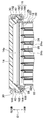
- FIG. 2 is a cross-sectional view taken along line II-II of FIG.
- FIG. 2 is a perspective view of a portion of the heat exchanger as seen in the direction of the arrow III in FIG. 1; It is a top view of a part of heat exchanger seen in the direction of IV arrow of FIG. It is an enlarged view of the V section of FIG. It is the top view which looked at the tank main-body part in FIG. 4 from the other side of the 1st direction.
- It is a figure for demonstrating the manufacturing method of the heat exchanger in 1st Embodiment, and is sectional drawing of the heat exchanger in the state before crimping and fixing.
- FIG. 9 It is a figure which shows stress distribution of the XI section in FIG.
- FIG. 3 It is the perspective view which looked at the caulking plate in FIG. 3 in the direction of the XII arrow.
- FIG. 3 It is a figure which shows stress distribution of the part XIII in FIG.
- the heat exchanger 10 of the present embodiment shown in FIG. 1 is an intercooler that cools the intake air by heat exchange between the intake air pressurized by the supercharger and becoming high temperature and the cooling water.
- the heat exchanger 10 includes a heat exchange core 12 and a tank body 14.
- the heat exchange core 12 exchanges heat between the intake air and the cooling water.
- the heat exchange core 12 is made of a metal having a high thermal conductivity such as aluminum.
- the tank body portion 14 the intake air flowing into the heat exchange core 12 or the intake air flowing out from the heat exchange core 12 flows.
- the tank body 14 is made of synthetic resin.
- the tank body 14 may be made of metal.
- the heat exchange core side of the tank body 14 is joined to the heat exchange core 12 via the caulking plate 16.
- the opposite side of the heat exchange core side of the tank body portion 14 is connected to a not-shown supercharger or an unshown engine intake port via a hose or the like.
- the heat exchange core 12 has a caulking plate 16.
- the caulking plate 16 is a component of the heat exchange core 12.
- the caulking plate 16 is caulked and fixed to the tank body portion 14.
- the caulking is to connect a plurality of parts by plastic working a part of the plurality of parts. Therefore, the caulking plate 16 is a bonding plate for bonding the heat exchange core 12 and the tank body portion 14.
- the heat exchange core 12 has an inlet pipe 18 and an outlet pipe 20.
- the inlet pipe 18 constitutes an inlet for the cooling water of the heat exchange core 12.
- the inlet pipe 18 is connected to a pipe (not shown) through which the cooling water flows toward the heat exchange core 12.
- the outlet pipe 20 constitutes an outlet of the cooling water of the heat exchange core 12.
- the outlet pipe 20 is connected to a pipe (not shown) through which the cooling water flowing out of the heat exchange core 12 flows.
- the heat exchange core 12 has a housing 22, a plurality of tubes 24, and a plurality of fins 26.
- the housing 22 forms an outer shell of the heat exchange core 12.
- the housing 22 accommodates therein a laminated body in which a plurality of tubes 24 and a plurality of fins 26 are laminated.
- Each of the plurality of tubes 24 forms an inner tube space 24a inside.
- Each of the plurality of tubes 24 is stacked with an interval between each other.
- Each of the plurality of fins 26 is disposed between adjacent ones of the plurality of tubes 24.
- Each of the plurality of fins 26 is brazed to each of the plurality of tubes 24.
- the tube outer space 24b outside the plurality of tubes 24 in the interior of the housing 22 is an intake flow passage through which intake air flows.
- Each tube inner space 24 a of the plurality of tubes 24 is a cooling water flow path through which the cooling water flows.
- the plurality of fins 26 promote heat exchange between the intake air and the cooling water by increasing the heat transfer area on the intake side.
- the intake corresponds to the first fluid.
- the intake flow passage corresponds to a first flow passage through which the first fluid flows.
- the cooling water corresponds to the second fluid.
- the cooling water channel corresponds to a second channel through which the second fluid flows.
- the tank body 14 forms a tank space 14a inside.
- the tank space 14a communicates with the tube outer space 24b.
- the caulking plate 16 is joined to the housing 22 by brazing.
- the caulking plate 16 has an inner wall portion 162, an outer wall portion 164 and a bottom wall portion 166.
- the outer wall portion 164 is positioned more outward than the inner wall portion 162 on the tank main body portion 14.
- the outer wall portion 164 faces the inner wall portion 162 with a space in between.
- Bottom wall portion 166 extends in a direction intersecting with inner wall portion 162 and outer wall portion 164.
- the bottom wall portion 166 connects the inner wall portion 162 and the outer wall portion 164.
- the inner wall portion 162, the outer wall portion 164, and the bottom wall portion 166 form a groove having a U-shaped cross section.
- the inner wall portion 162 of the caulking plate 16 is brazed to the flat end 222 of the housing 22.
- the bottom wall portion 166 of the caulking plate 16 is brazed to the L-shaped end portion 224 of the housing 22.
- the inner wall portion 162 and the outer wall portion 164 extend from the bottom wall portion 166 in the first direction D1.
- the bottom wall portion 166 is continuous with one end of each of the inner wall portion 162 and the outer wall portion 164 in the first direction D1.
- the first direction D1 is an extension direction of each of the plurality of tubes 24.
- the first direction D1 is the direction in which the heat exchange core 12 and the tank body 14 are aligned.
- one side of the first direction D1 is the heat exchange core side.
- the other side opposite to the first direction D1 is the tank body side.
- the outer wall portion 164 corresponds to a first wall portion extending in the first direction.
- the bottom wall portion 166 corresponds to a second wall portion connected to one side in the first direction of the first wall portion.
- the heat exchanger 10 also includes a packing 28.
- the packing 28 is a sealing member that seals the joint between the heat exchange core 12 and the tank main body 14.
- the packing 28 is made of an elastic member such as synthetic rubber.
- the packing 28 and the end 142 of the tank body 14 are disposed between the inner wall 162 and the outer wall 164. In this state, the outer wall 146 covers the outside of the tank body 14.
- the outer wall portion 164 has a plurality of caulking portions 30.
- Each caulking portion 30 is provided on the other side of the outer wall portion 164 in the first direction D1.
- the caulking portion 30 is a portion in which a part of the outer wall portion 164 is plastically deformed in order to caulk and fix the caulking plate 16 to the tank body portion 14.
- the respective caulking portions 30 and the bottom wall portion 166 sandwich and hold the end portion 142 of the tank main body portion 14 in the first direction D1. Therefore, the end 142 of the tank body 14 is a held portion.
- Each caulking portion 30 holds the end 142 of the tank body 14 in a state in which the packing 28 is compressed in the first direction D1. Therefore, each caulking portion 30 is a pressing portion that presses the end portion 142 of the tank main body portion 14.
- FIG. 3 is a perspective view of the tank body 14 and the caulking plate 16 in the caulked and fixed state.
- FIG. 4 is a side view of the tank body 14 and the caulking plate 16 in the caulked and fixed state.
- the heat exchange core 12 is not shown.
- the tank body portion 14 has a plurality of recesses 32 in a portion covered by the outer wall portion 164 of the caulking plate 16.
- the plurality of concave portions 32 are formed in the tank main body 14 at a portion different from the end 142 of the tank main body 14 in the first direction D1.
- Each of the plurality of caulking portions 30 is located in each of the plurality of concave portions 32.
- each slit 40 is an opening formed on one side in the first direction D1 of each caulking portion 30 of the outer wall portion 164, that is, an opening formed adjacent to the bottom wall portion 166 side.
- Each slit 40 is formed to define the position of each caulking portion 30 in the first direction D1.
- each slit 40 has a shape extending in the second direction D2 on the outer surface 164 a of the outer wall portion 164.
- the second direction D2 is a direction that intersects the first direction D1.
- the second direction D2 is a direction along the periphery of the wall portion of the tank body portion 14 connected to the heat exchange core 12.
- the end portions 44 and 46 in the second direction D2 of the slit 40 have a rounded shape.
- the ends 44 and 46 in the second direction D2 of the slit 40 face each other in the second direction D2.
- the slit 40 has a slit space 401 and a slit forming surface 402 which forms the slit space 401.
- the slit forming surface 402 surrounds the slit space 401.
- the principal surface 403 of the slit formation surface 402 located on the other side in the first direction D1 forms a straight side 42 on the outer surface 164 a of the outer wall portion 164.
- the end surfaces 404 and 405 of the slit forming surface 402 located at both ends in the second direction D2 form curved sides 44 and 46 on the outer surface 164 a of the outer wall portion 164.
- portions where the sides forming the outer shape of the slit 40 are curved are the end portions 44 and 46 in the second direction D 2 of the slit 40.
- the caulking portion 30 is located outside the outer wall portion 164 in the circumferential direction of the tank body portion 14.
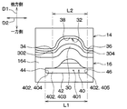
- the recess 32 has two recess initiations 34, 36 and a bottom 38 located between the two recess initiations 34, 36.
- the two recess start portions 34, 36 are aligned in the second direction D2.
- the respective recess start portions 34 and 36 are portions of the wall surface 144 of the tank main body portion 14 where the recess is started.
- the part where the depression is started is the part where the bending starts from the flat surface.
- FIG. 6 is a view when the recess 32 is viewed from the other side of the first direction D1, that is, the upper side of FIG.
- the virtual surface V1 which covers the recessed part 32 is shown in figure.
- the virtual surface V1 is a surface obtained by extending a portion of the wall surface 144 of the tank main body 14 where the recess 32 is not formed to the recess 32 side.
- the portions where the virtual surface V1 and the recess 32 are in contact with each other are two depression start portions 34 and 36.
- the caulking portion 30 is a portion of the outer wall portion 164 adjacent to the slit 40 in the first direction D1.
- the caulking portion 30 is a portion of the outer wall portion 164 that is bent toward the bottom portion 38 of the recess 32 as two starting points 302 and 304 at positions in contact with the two recess start portions 34 and 36 of the recess 32. is there.
- the caulking portion 30 is a portion between the two starting portions 302 and 304 and is a portion projecting toward the recess 32 of the tank body portion 14.
- one of the two recess start portions 34 and 36 is the first recess start portion 34
- the other of the two recess start portions 34 and 36 is the second recess start portion 36.
- One of the two ends 44 and 46 in the second direction D 2 of the slit 40 is the first end 44
- the other of the two ends 44 and 46 is the second end 46.
- One of the two starting points 302, 304 is a first starting point 302, and the other of the two starting points 302, 304 is a second starting point 304.
- the first recess start portion 34, the first end 44 and the first start portion 302 are located on the same side in the second direction. That is, the side where the first starting point portion 302 of the two starting point portions 302 and 304 is located in the second direction, the side where the first end 44 at the two end portions 44 and 46 is located in the second direction, It is the same as the side where the first dent start part 34 in the dent start parts 34, 36 is positioned in the second direction.
- the first starting point portion 302 corresponds to one starting point portion of the two starting point portions.
- the first end 44 corresponds to one of the two ends in the second direction of the opening that is located on the same side in the second direction as the one starting point.
- the length L 1 of the slit 40 in the second direction D 2 is longer than the distance L 2 between the two recess start portions 34 and 36 of the recess 32. Furthermore, the first recess start portion 34 of the recess 32 is separated from the first end 44 of the slit 40 in the second direction D2. Therefore, the first starting point portion 302 of the caulking portion 30 corresponding to the first recess start portion 34 of the recess 32 is separated from the first end 44 of the slit 40 in the second direction D2.
- the first starting point portion 302 of the caulking portion 30 is located outside the second starting point portion 304 of the outer wall portion 164 shown in FIG. 5 in the circumferential direction of the tank main body 14. In other words, the first starting point portion 302 of the caulking portion 30 is located closer to the corner portion of the tank body 14 than the second starting point portion 304.
- the second recess start portion 36 of the recess 32 is at the same position as the second end 46 of the slit 40 in the second direction D2. Therefore, the second starting point portion 304 of the caulking portion 30 corresponding to the second recess start portion 36 of the recess 32 is at the same position in the second direction D2 with respect to the second end 46 of the slit 40.
- FIG. 7 corresponds to FIG.
- FIG. 8 corresponds to FIG.
- the heat exchange core 12 is not shown.
- the heat exchange core 12 shown in FIG. 7 is prepared.
- the heat exchange core 12 has a caulking plate 16 caulked and fixed to the tank body portion 14.
- the caulking plate 16 has an inner wall portion 162, an outer wall portion 164, and a bottom wall portion 166.
- the outer wall portion 164 is formed with a slit 40 for forming the caulking portion 30.
- the caulking portion 30 is not formed in the outer wall portion 164.
- the tank body 14 shown in FIGS. 7 and 8 is prepared. At this time, the tank body 14 has a recess 32 for forming the caulking portion 30.
- the recess 32 has two recess initiations 34, 36 and a bottom 38.
- the heat exchange core 12 and the tank body portion 14 are assembled.
- the outer wall portion 164 is disposed at a position where the outer wall portion 164 of the caulking plate 16 covers the outside of the tank body portion 14. More specifically, as shown in FIG. 7, the packing 28 and the end 142 of the tank main body 14 are disposed in a space surrounded by the inner wall 162, the outer wall 164 and the bottom wall 166 of the caulking plate 16. Do.
- the heat exchange core 12 and the tank body portion 14 are crimped and fixed.
- a load is applied to the tank body 14 in one side of the first direction D1.
- the packing 28 is compressed in the first direction D1.
- the portion 31 adjacent to the slit 40 of the outer wall portion 164 of the caulking plate 16 is pushed toward the bottom 38 of the recess 32.
- the caulking portion 30 is formed.
- the caulking portion 30 and the bottom wall portion 166 hold the end portion 142 of the tank body portion 14 in the first direction D1.
- the formation surface on the other side in the first direction D1 is the end surface of the caulking portion 30 in contact with the end portion 142 of the tank body portion 14. That is, the position of the end face of the caulking portion 30 is defined by the slit 40.
- the length L1 in the second direction D2 of the slit 40 is longer than the interval L2 of the two dent start parts 34, 36.
- the replacement core 12 Thereby, at the time of the above-described caulking fixation, the first direction D1 of the slit 40 is separated from the first end 44 of the slit 40 in the second direction D2 so that the first starting point 302 of the caulking portion 30 is separated.
- the adjacent part 31 at can be bent.
- the heat exchanger 10 of the present embodiment can be manufactured.
- the heat exchanger 10 of this embodiment and the heat exchanger J10 of Comparative Example 1 shown in FIG. 9 are compared.
- the heat exchange core 12 is not shown.
- the length L1 of the slit 40 in the second direction D2 is the same as the distance L2 between the two recess start portions 34 and 36 of the recess 32.
- the first starting point portion 302 of the caulking portion 30 is at the same position as the first end 44 of the slit 40 in the second direction D2.
- the other configuration of the heat exchanger J10 of Comparative Example 1 is the same as the heat exchanger 10 of the present embodiment.
- FIG. 10 is a view of the caulking plate 16 of FIG. 9 as viewed in the direction of the X arrow.
- FIG. 10 the inner surface 164b of the outer wall portion 164 is shown.
- FIG. 11 is an enlarged view of a part XI of FIG. “The first start point portion 302 of the caulking portion 30 is at the same position in the second direction D2 as the first end portion 44 of the slit 40” means, as shown in FIG. 11, the first start point portion 302 of the slit 40 in the second direction D2.
- the range R44 is a range in which the sides forming the outer shape of the slit 40 on the inner surface 164b and the outer surface 164a of the outer wall portion 164 are curved.
- the ends 44 and 46 in the second direction D2 of the slit 40 are rounded at the outer surface 164a and the inner surface 164b of the outer wall portion 164 as in the heat exchanger 10 of the present embodiment. It has a round shape. For this reason, the edges of the ends 44, 46 are stressed when the caulking plate 16 is stressed as compared with the case where the ends 44, 46 are not rounded and the ends 44, 46 have corners. Stress concentration in the part is suppressed.
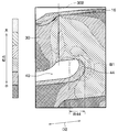
- the first starting point portion 302 of the caulking portion 30 is separated from the first end 44 of the slit 40 in the second direction D2. Therefore, as shown in FIGS. 12 and 13, in the heat exchanger 10 of the present embodiment, stress applied to the peripheral portion B1 of the first end 44 of the slit 40 as compared to the heat exchanger J10 of the comparative example 1. Becomes smaller.
- FIG. 12 and 13 show analysis results of stress applied to the caulking plate 16 of the heat exchanger 10 of the present embodiment. 12 and 13 show analysis results under the same conditions as the heat exchanger J10 of Comparative Example 1.
- FIG. FIG. 12 is a view of the caulking plate 16 of FIG. 3 as viewed in the arrow direction of XII. In FIG. 12, the inner surface 164b of the outer wall portion 164 is shown.
- FIG. 13 is a view showing a stress distribution in a part XIII of FIG.
- the first starting point portion 302 of the caulking portion 30 is separated from the range R44 in the second direction D2. Assuming that the magnitude of stress at the maximum stress portion in the peripheral portion B1 of FIG. 11 is 100, the magnitude of stress at the maximum stress portion of the peripheral portion B1 in FIG. 13 is 78.
- the first end 44 of the slit 40 has a rounded shape. That is, in the outer surface 164a and the inner surface 164b of the outer wall portion 164, the first end 44 of the slit 40 has a curved shape. However, the first end 44 of the slit 40 may be linear in the outer surface 164 a and the inner surface 164 b of the outer wall portion 164. Also in this case, as in the first embodiment, the first starting point portion 302 of the caulking portion 30 may be separated from the first end 44 of the slit 40 in the second direction D2. Thereby, the same effect as that of the first embodiment can be obtained.
- the heat exchanger is a water-cooled intercooler, but it may be an air-cooled intercooler.
- the cooling air corresponds to the second fluid.
- the heat exchanger may be a heat exchanger for other applications. Examples of heat exchangers for other uses include a radiator for radiating cooling water such as engine cooling water, and a heater core for heating using cooling water such as engine cooling water as a heat source. In either case of the radiator and the heater core, one of the cooling water and the air corresponds to the first fluid, and the other of the cooling water and the air corresponds to the second fluid.
- the heat exchanger comprises a heat exchange core and a tank body.
- the heat exchange core has a caulking plate caulked to the tank body.
- the caulking plate has a first wall and a second wall.
- the first wall portion has a pressing portion that presses the held portion of the tank main body.
- the holding portion and the second wall hold and hold the held portion of the tank body in the first direction.
- the tank body has a recess in which the pressing portion is positioned.
- the recess has two recess starts aligned in the second direction and a bottom located between the two recess starts. An opening is formed adjacent to one side of the first wall in the first direction of the pressing portion.
- the pressing portion is a portion adjacent to the opening in the first direction of the first wall and is bent toward the bottom of the recess with two starting points at positions contacting with the two recess start portions. Part.
- the length of the opening in the second direction is longer than the distance between the two recess start portions.
- One of the two starting points is separated from the one of the two ends of the opening in the second direction in the second direction.
- one end of the opening in the outer surface and the inner surface of the first wall portion has a rounded shape.
- stress concentration in the periphery of the end of the opening is suppressed as compared with the case where the end is not rounded.
- one end of the opening in the outer surface and the inner surface of the first wall portion has a linear shape.
- the shape of the end of the opening can be such a shape.
- the method of manufacturing a heat exchanger includes preparing a heat exchange core, preparing a tank body, assembling the heat exchange core and the tank body, and heat. And caulking and fixing the replacement core and the tank body.
- the heat exchange core is prepared in which the length in the second direction of the opening is longer than the distance between the two recess start parts.
- at least one of the two starting points is located in the second direction away from one of the two ends in the second direction of the opening. , Bend the next part of the opening.
- the heat exchange core in preparing the heat exchange core, is prepared in which one end of the opening in the outer surface and the inner surface of the first wall is rounded. .
- the end has a rounded shape, stress concentration in the periphery of the end of the opening is suppressed as compared with the case where the end is not rounded.
- stress concentration in the peripheral portion of the end of the opening can be further suppressed. Therefore, the reduction in the strength of the caulking plate can be further suppressed.
- the heat exchange core in preparing the heat exchange core, is prepared in which one end of the opening in the outer surface and the inner surface of the first wall portion is linear.
- the shape of the end of the opening can be such a shape.
Landscapes
- Engineering & Computer Science (AREA)
- Mechanical Engineering (AREA)
- Physics & Mathematics (AREA)
- Thermal Sciences (AREA)
- General Engineering & Computer Science (AREA)
- Details Of Heat-Exchange And Heat-Transfer (AREA)
- Heat-Exchange Devices With Radiators And Conduit Assemblies (AREA)
Abstract
熱交換器は、熱交換コアとタンク本体部(14)とを備える。熱交換コアは、タンク本体部にかしめ固定されるかしめプレート(16)を有する。かしめプレートは、タンク本体部の外側を覆う第1壁部(164)を有する。第1壁部は、タンク本体部の被保持部を押さえる押さえ部(30)を有する。タンク本体部は、押さえ部が内部に位置する凹部(32)を有する。凹部は、第2方向(D2)に並ぶ2つの凹み開始部(34、36)を有する。第1壁部のうち押さえ部の隣りに開口部(40)が形成されている。押さえ部は、2つの凹み開始部のそれぞれと接する位置を2つの起点部(302、304)として、凹部に向かって曲がっている。開口部の第2方向での長さ(L1)は、2つの凹み開始部の間隔(L2)よりも長い。2つの起点部の一方の起点部(302)は、開口部の一方の端部(44)から第2方向で離れている。
Description
本出願は、2017年9月27日に出願された日本特許出願番号2017-186810号に基づくもので、ここにその記載内容が参照により組み入れられる。
本開示は、熱交換器およびその製造方法に関するものである。
特許文献1に、熱交換コアとタンク本体部とがかしめ固定された熱交換器が開示されている。この熱交換器では、熱交換コアは、タンク本体部にかしめ固定されるかしめプレートを有している。かしめ固定の際では、かしめプレートの一部が変形されることで押さえ部が形成される。形成された押さえ部とかしめプレートの他の一部とが、タンク本体部の被保持部を第1方向に挟んで保持する。これによって、熱交換コアとタンク本体部とが、かしめ固定される。
なお、かしめプレートには、押さえ部を形成するための開口部が形成されている。かしめプレートのうち開口部の第1方向での隣りの部分がタンク本体部側に変形することで、押さえ部が形成される。この開口部は、第1方向に対して交差する第2方向に延びている。
なお、かしめプレートには、押さえ部を形成するための開口部が形成されている。かしめプレートのうち開口部の第1方向での隣りの部分がタンク本体部側に変形することで、押さえ部が形成される。この開口部は、第1方向に対して交差する第2方向に延びている。
ところで、本発明者が、熱交換コアとタンク本体部とがかしめ固定された状態のかしめプレートの強度を解析した。その結果、押さえ部の変形の起点部と開口部の第2方向での端部との位置関係によっては、かしめプレートのうち開口部の端部の周辺部において、著しく強度が低下することが見出された。
本開示は、かしめプレートの強度の低下を抑制できる熱交換器およびその製造方法を提供することを目的とする。
上記目的を達成するため、本開示の1つの観点によれば、
第1流体と第2流体とを熱交換させる熱交換器は、
第1流体が流れる第1流路と第2流体が流れる第2流路とを形成する熱交換コアと、
第1流路に連なるタンク空間を形成するタンク本体部とを備え、
熱交換コアは、タンク本体部にかしめ固定されるかしめプレートを有し、
かしめプレートは、第1方向に延びてタンク本体部の外側を覆う第1壁部と、第1壁部の第1方向での一方側に連なる第2壁部とを有し、
第1壁部は、第1壁部のうち第1方向での他方側に設けられた、タンク本体部の被保持部を押さえる押さえ部を有し、
押さえ部と第2壁部とは、タンク本体部の被保持部を第1方向に挟んで保持しており、
タンク本体部は、被保持部とは異なる部位に、押さえ部が内部に位置する凹部を有し、
凹部は、第1方向に交差する第2方向に並ぶ2つの凹み開始部と、2つの凹み開始部の間に位置する底部とを有し、
第1壁部のうち押さえ部の第1方向での一方側の隣りに開口部が形成されており、
押さえ部は、第1壁部のうち開口部の第1方向での隣りの部分であって、2つの凹み開始部のそれぞれと接する位置を2つの起点部として、凹部の底部に向かって曲がっている部分であり、
開口部の第2方向での長さは、2つの凹み開始部の間隔よりも長くなっており、
2つの起点部の一方の起点部は、開口部の第2方向での2つの端部のうち一方の起点部と第2方向で同じ側に位置する一方の端部から第2方向で離れている。
第1流体と第2流体とを熱交換させる熱交換器は、
第1流体が流れる第1流路と第2流体が流れる第2流路とを形成する熱交換コアと、
第1流路に連なるタンク空間を形成するタンク本体部とを備え、
熱交換コアは、タンク本体部にかしめ固定されるかしめプレートを有し、
かしめプレートは、第1方向に延びてタンク本体部の外側を覆う第1壁部と、第1壁部の第1方向での一方側に連なる第2壁部とを有し、
第1壁部は、第1壁部のうち第1方向での他方側に設けられた、タンク本体部の被保持部を押さえる押さえ部を有し、
押さえ部と第2壁部とは、タンク本体部の被保持部を第1方向に挟んで保持しており、
タンク本体部は、被保持部とは異なる部位に、押さえ部が内部に位置する凹部を有し、
凹部は、第1方向に交差する第2方向に並ぶ2つの凹み開始部と、2つの凹み開始部の間に位置する底部とを有し、
第1壁部のうち押さえ部の第1方向での一方側の隣りに開口部が形成されており、
押さえ部は、第1壁部のうち開口部の第1方向での隣りの部分であって、2つの凹み開始部のそれぞれと接する位置を2つの起点部として、凹部の底部に向かって曲がっている部分であり、
開口部の第2方向での長さは、2つの凹み開始部の間隔よりも長くなっており、
2つの起点部の一方の起点部は、開口部の第2方向での2つの端部のうち一方の起点部と第2方向で同じ側に位置する一方の端部から第2方向で離れている。
ここで、開口部の第2方向での長さが2つの凹み開始部の間隔と同じ場合、押さえ部の一方の起点部と開口部の一方の端部とは、第2方向で同じ位置となる。この場合、かしめプレートに応力がかかると、かしめプレートのうち開口部の端部の周辺部に応力集中が生じる。このように、かしめプレートのうち開口部の端部の周辺部の強度が著しく低下することが、本発明者によって見出された。
そこで、上記の観点の熱交換器では、開口部の第2方向での長さは、2つの凹み開始部の間隔よりも長くなっている。そして、押さえ部の一方の起点部は、開口部の一方の端部から第2方向で離れている。これによれば、かしめプレートに応力がかかったときに、かしめプレートのうち開口部の端部の周辺部に生じる応力集中を抑制できる。よって、かしめプレートの強度の低下を抑制することができる。
また、本開示の別の観点によれば、第1流体が流れる第1流路と第2流体が流れる第2流路とを形成する熱交換コアと、第1流路に連なるタンク空間を形成するタンク本体部とを備え、第1流体と第2流体とを熱交換させる熱交換器の製造方法は、
タンク本体部にかしめ固定されるかしめプレートを有し、かしめプレートは、第1方向に延びる第1壁部と、第1壁部の第1方向での一方側に連なる第2壁部とを有し、押さえ部を形成するための開口部が第1壁部に形成されている熱交換コアを用意することと、
押さえ部を形成するための凹部を有し、凹部が、第1方向に交差する第2方向に並ぶ2つの凹み開始部と、2つの凹み開始部の間に位置する底部とを有するタンク本体部を用意することと、
かしめプレートの第1壁部がタンク本体部の外側を覆う位置に第1壁部を配置して、熱交換コアとタンク本体部とを組み付けることと、
かしめプレートの第1壁部のうち開口部の第1方向での隣りの部分を、タンク本体部の凹部の底部に向けて押し込み、2つの凹み開始部のそれぞれと接する位置を2つの起点部として、開口部の隣りの部分を底部に向かって曲げて押さえ部を形成し、押さえ部と第2壁部とによって、タンク本体部の被保持部を第1方向に挟んで保持することで、熱交換コアとタンク本体部とをかしめ固定することとを含み、
熱交換コアを用意することにおいては、開口部の第2方向での長さが2つの凹み開始部の間隔よりも長くなっている熱交換コアを用意し、
かしめ固定を行うことにおいては、2つの起点部の少なくとも一方の起点部が、開口部の第2方向での2つの端部のうち一方の起点部と第2方向で同じ側に位置する一方の端部から第2方向で離れた位置にあるように、開口部の隣りの部分を曲げる。
タンク本体部にかしめ固定されるかしめプレートを有し、かしめプレートは、第1方向に延びる第1壁部と、第1壁部の第1方向での一方側に連なる第2壁部とを有し、押さえ部を形成するための開口部が第1壁部に形成されている熱交換コアを用意することと、
押さえ部を形成するための凹部を有し、凹部が、第1方向に交差する第2方向に並ぶ2つの凹み開始部と、2つの凹み開始部の間に位置する底部とを有するタンク本体部を用意することと、
かしめプレートの第1壁部がタンク本体部の外側を覆う位置に第1壁部を配置して、熱交換コアとタンク本体部とを組み付けることと、
かしめプレートの第1壁部のうち開口部の第1方向での隣りの部分を、タンク本体部の凹部の底部に向けて押し込み、2つの凹み開始部のそれぞれと接する位置を2つの起点部として、開口部の隣りの部分を底部に向かって曲げて押さえ部を形成し、押さえ部と第2壁部とによって、タンク本体部の被保持部を第1方向に挟んで保持することで、熱交換コアとタンク本体部とをかしめ固定することとを含み、
熱交換コアを用意することにおいては、開口部の第2方向での長さが2つの凹み開始部の間隔よりも長くなっている熱交換コアを用意し、
かしめ固定を行うことにおいては、2つの起点部の少なくとも一方の起点部が、開口部の第2方向での2つの端部のうち一方の起点部と第2方向で同じ側に位置する一方の端部から第2方向で離れた位置にあるように、開口部の隣りの部分を曲げる。
ここで、開口部の第2方向での長さが2つの凹み開始部の間隔と同じ場合、押さえ部の一方の起点部と開口部の一方の端部とは、第2方向で同じ位置となる。この場合、かしめプレートに応力がかかると、かしめプレートのうち開口部の端部の周辺部に応力集中が生じる。このように、かしめプレートのうち開口部の端部の周辺部の強度が著しく低下することが、本発明者によって見出された。
そこで、上記の観点の熱交換器の製造方法では、開口部の第2方向での長さが2つの凹み開始部の間隔よりも長くなっている熱交換コアを用いる。そして、押さえ部の一方の起点部が、開口部の一方の端部から第2方向で離れた位置にあるように、開口部の隣りの部分を曲げる。これによれば、かしめプレートに応力がかかったときに、かしめプレートのうち開口部の端部の周辺部に生じる応力集中を抑制できる。よって、かしめプレートの強度の低下を抑制することができる。
なお、各構成要素等に付された括弧付きの参照符号は、その構成要素等と後述する実施形態に記載の具体的な構成要素等との対応関係の一例を示すものである。
以下、本開示の実施形態について図に基づいて説明する。なお、以下の各実施形態相互において、互いに同一もしくは均等である部分には、同一符号を付して説明を行う。
(第1実施形態)
図1に示す本実施形態の熱交換器10は、過給機にて加圧されて高温になった吸気と、冷却水とを熱交換させて吸気を冷却するインタークーラである。
図1に示す本実施形態の熱交換器10は、過給機にて加圧されて高温になった吸気と、冷却水とを熱交換させて吸気を冷却するインタークーラである。
図1に示すように、熱交換器10は、熱交換コア12と、タンク本体部14とを備える。熱交換コア12は、吸気と冷却水とを熱交換させる。熱交換コア12は、アルミニウム等の熱伝導率が高い金属で構成される。
タンク本体部14は、熱交換コア12に流入する吸気、または、熱交換コア12から流出した吸気が流れる。タンク本体部14は、合成樹脂で構成される。タンク本体部14は、金属で構成されていてもよい。タンク本体部14の熱交換コア側は、かしめプレート16を介して熱交換コア12に接合される。タンク本体部14の熱交換コア側の反対側は、ホース等を介して不図示の過給器、または、不図示のエンジンの吸気ポートと接続される。
熱交換コア12は、かしめプレート16を有する。かしめプレート16は、熱交換コア12の構成部品である。かしめプレート16は、タンク本体部14にかしめ固定される。かしめ固定とは、複数の部品の一部を塑性加工して複数の部品同士を接合することである。したがって、かしめプレート16は、熱交換コア12とタンク本体部14とを接合する接合プレートである。
熱交換コア12は、入口用配管18と出口用配管20とを有する。入口用配管18は、熱交換コア12の冷却水の入口を構成する。入口用配管18は、熱交換コア12に向かって冷却水が流れる不図示の配管と接続される。出口用配管20は、熱交換コア12の冷却水の出口を構成する。出口用配管20は、熱交換コア12から流出した冷却水が流れる不図示の配管と接続される。
図2に示すように、熱交換コア12は、ハウジング22と、複数のチューブ24と、複数のフィン26とを有する。ハウジング22は、熱交換コア12の外殻を形成している。ハウジング22は、複数のチューブ24と複数のフィン26とが積層された積層体を内部に収容している。複数のチューブ24のそれぞれは、内部にチューブ内側空間24aを形成する。複数のチューブ24のそれぞれは、互いに間を空けて積層されている。複数のフィン26のそれぞれは、複数のチューブ24のうち隣り合うチューブ24の間に配置されている。複数のフィン26のそれぞれは、複数のチューブ24のそれぞれにろう付けにて接合されている。
ハウジング22の内部のうち複数のチューブ24の外側のチューブ外側空間24bが、吸気が流れる吸気流路である。複数のチューブ24のそれぞれのチューブ内側空間24aが、冷却水が流れる冷却水流路である。複数のフィン26は、吸気側の伝熱面積を増大させることで、吸気と冷却水との熱交換を促進させる。本実施形態では、吸気が第1流体に相当する。吸気流路が第1流体が流れる第1流路に相当する。冷却水が第2流体に相当する。冷却水流路が第2流体が流れる第2流路に相当する。
タンク本体部14は、内部にタンク空間14aを形成する。タンク空間14aは、チューブ外側空間24bに連なる。
かしめプレート16は、ろう付けにてハウジング22に接合されている。かしめプレート16は、内壁部162と外壁部164と底壁部166とを有する。外壁部164は、内壁部162よりもタンク本体部14の外側に位置する。外壁部164は、内壁部162と間を空けて向かい合っている。底壁部166は、内壁部162および外壁部164に対して交差する方向に延びている。底壁部166は、内壁部162と外壁部164とをつないでいる。内壁部162と外壁部164と底壁部166とは、断面U字状の溝部を形成している。
かしめプレート16の内壁部162が、ハウジング22の平板状の端部222とろう付けされている。または、かしめプレート16の底壁部166が、ハウジング22の断面L字状の端部224とろう付けされている。
内壁部162と外壁部164は、底壁部166から第1方向D1に延びている。底壁部166は、内壁部162と外壁部164のそれぞれにおける第1方向D1での一方側の端部に連なっている。第1方向D1は、複数のチューブ24のそれぞれの延伸方向である。換言すると、第1方向D1は、熱交換コア12とタンク本体部14との並び方向である。図2に示すように、第1方向D1の一方側が熱交換コア側である。第1方向D1の反対側である他方側がタンク本体部側である。本実施形態では、外壁部164が第1方向に延びている第1壁部に相当する。底壁部166が第1壁部の第1方向での一方側に連なる第2壁部に相当する。
また、熱交換器10は、パッキン28を備える。パッキン28は、熱交換コア12とタンク本体部14との接合部をシールするシール部材である。パッキン28は、合成ゴム等の弾性部材で構成される。
内壁部162と外壁部164との間に、パッキン28とタンク本体部14の端部142とが配置されている。この状態で、外壁部146は、タンク本体部14の外側を覆っている。
外壁部164は、複数のかしめ部30を有する。それぞれのかしめ部30は、外壁部164のうち第1方向D1での他方側に設けられている。かしめ部30は、かしめプレート16をタンク本体部14にかしめ固定するために、外壁部164の一部が塑性変形された部分である。それぞれのかしめ部30と底壁部166とは、タンク本体部14の端部142を第1方向D1に挟んで保持している。したがって、タンク本体部14の端部142は、被保持部である。また、それぞれのかしめ部30は、パッキン28を第1方向D1で圧縮させた状態で、タンク本体部14の端部142を押さえている。したがって、それぞれのかしめ部30は、タンク本体部14の端部142を押さえる押さえ部である。
図3は、かしめ固定された状態のタンク本体部14とかしめプレート16の斜視図である。図4は、かしめ固定された状態のタンク本体部14とかしめプレート16の側面図である。図3、4では、熱交換コア12の図示が省略されている。図3に示すように、タンク本体部14は、かしめプレート16の外壁部164に覆われる部位に複数の凹部32を有する。複数の凹部32は、タンク本体部14のうちタンク本体部14の端部142とは第1方向D1で異なる部位に形成されている。複数の凹部32のそれぞれの内部に、複数のかしめ部30のそれぞれが位置している。
図3、4に示すように、かしめプレート16には、複数のスリット40が形成されている。それぞれのスリット40は、外壁部164のうちそれぞれのかしめ部30の第1方向D1での一方側、すなわち、底壁部166側の隣りに形成された開口部である。それぞれのスリット40は、それぞれのかしめ部30の第1方向D1での位置を規定するために形成されている。
図4に示すように、それぞれのスリット40は、外壁部164の外面164aにおいて、第2方向D2に延びた形状である。第2方向D2は、第1方向D1に交差する方向である。第2方向D2は、タンク本体部14のうち熱交換コア12と接続される壁部の周囲に沿った方向である。外壁部164の外面164aにおいて、スリット40の第2方向D2での端部44、46は、丸みを帯びた形状である。スリット40の第2方向D2での端部44、46は、第2方向D2で向かい合っている。
スリット40について詳述する。図5に示すように、スリット40は、スリット空間401と、スリット空間401を形成するスリット形成面402を有する。スリット形成面402は、スリット空間401を囲んでいる。スリット形成面402のうち第1方向D1の他方側に位置する主面403は、外壁部164の外面164aにおいて直線の辺42をなしている。スリット形成面402のうち第2方向D2の両端に位置する端面404、405は、外壁部164の外面164aにおいて曲線の辺44、46をなしている。外壁部164の外面164aにおいて、スリット40の外形をなす辺が曲線である部分が、スリット40の第2方向D2での端部44、46である。
図5を用いて、複数のかしめ部30のうち図3のV部に示すかしめ部30について説明する。このかしめ部30は、外壁部164のうちタンク本体部14の周方向での外側に位置する。
図5に示すように、凹部32は、2つの凹み開始部34、36と、2つの凹み開始部34、36の間に位置する底部38とをする。2つの凹み開始部34、36は、第2方向D2に並んでいる。それぞれの凹み開始部34、36は、タンク本体部14の壁面144のうち凹みが開始されている部分である。凹みが開始されている部分とは、平坦な面から曲がり始めている部分である。
図6は、第1方向D1の他方側、すなわち、図4の上側から凹部32を見たときの図である。図6では、凹部32を覆う仮想面V1を図示している。仮想面V1は、タンク本体部14の壁面144のうち凹部32が形成されていない部分を凹部32側に延長させた面である。仮想面V1と凹部32とが接する部分が、2つの凹み開始部34、36である。
図5に示すように、かしめ部30は、外壁部164のうちスリット40の第1方向D1での隣りの部分である。かしめ部30は、外壁部164のうち、凹部32の2つの凹み開始部34、36のそれぞれと接する位置を2つの起点部302、304として、凹部32の底部38に向かって曲がっている部分である。換言すると、かしめ部30は、2つの起点部302、304との間の部分であって、タンク本体部14の凹部32に向けて突出している部分である。
ここで、2つの凹み開始部34、36の一方は第1凹み開始部34であり、2つの凹み開始部34、36の他方は第2凹み開始部36である。スリット40の第2方向D2での2つの端部44、46の一方は第1端部44であり、2つの端部44、46の他方は第2端部46である。2つの起点部302、304の一方は第1起点部302であり、2つの起点部302、304の他方は第2起点部304である。
第1凹み開始部34と第1端部44と第1起点部302とは、第2方向で同じ側に位置する。すなわち、2つの起点部302、304における第1起点部302が第2方向で位置する側と、2つの端部44、46における第1端部44が第2方向で位置する側と、2つの凹み開始部34、36における第1凹み開始部34が第2方向で位置する側とは、同じである。本実施形態では、第1起点部302が、2つの起点部の一方の起点部に相当する。第1端部44が、開口部の第2方向での2つの端部のうち一方の起点部と第2方向で同じ側に位置する一方の端部に相当する。
本実施形態では、スリット40の第2方向D2での長さL1は、凹部32の2つの凹み開始部34、36の間隔L2よりも長くなっている。さらに、凹部32の第1凹み開始部34は、スリット40の第1端部44から第2方向D2で離れている。このため、凹部32の第1凹み開始部34に対応するかしめ部30の第1起点部302は、スリット40の第1端部44から第2方向D2で離れている。
なお、かしめ部30の第1起点部302は、図5に示す外壁部164のうち第2起点部304よりもタンク本体部14の周方向での外側に位置する。換言すると、かしめ部30の第1起点部302は、第2起点部304よりもタンク本体部14の隅部側に位置する。
また、凹部32の第2凹み開始部36は、スリット40の第2端部46に対して、第2方向D2で同じ位置にある。このため、凹部32の第2凹み開始部36に対応するかしめ部30の第2起点部304は、スリット40の第2端部46に対して第2方向D2で同じ位置にある。
次に、図7、8を用いて、本実施形態の熱交換器10の製造方法について説明する。図7は、図2に対応している。図8は、図3に対応している。図8では、熱交換コア12の図示が省略されている。
まず、図7に示す熱交換コア12を用意する。このとき、熱交換コア12は、タンク本体部14にかしめ固定されるかしめプレート16を有する。かしめプレート16は、内壁部162と、外壁部164と、底壁部166とを有する。外壁部164には、かしめ部30を形成するためのスリット40が形成されている。図7、8に示すように、外壁部164には、かしめ部30は形成されていない。
さらに、図7、8に示すタンク本体部14を用意する。このとき、タンク本体部14は、かしめ部30を形成するための凹部32を有する。凹部32は、2つの凹み開始部34、36と、底部38とを有する。
続いて、熱交換コア12とタンク本体部14とを組み付ける。このとき、図7、8に示すように、かしめプレート16の外壁部164がタンク本体部14の外側を覆う位置に外壁部164を配置する。より具体的には、図7に示すように、かしめプレート16の内壁部162と外壁部164と底壁部166とに囲まれた空間に、パッキン28とタンク本体部14の端部142を配置する。
続いて、熱交換コア12とタンク本体部14とをかしめ固定する。このとき、図7に示すように、タンク本体部14に対して第1方向D1の一方側へ荷重をかける。パッキン28が第1方向D1に圧縮された状態とする。この状態で、かしめプレート16の外壁部164のうちスリット40の隣りの部分31を、凹部32の底部38に向けて押し込む。これにより、図5に示すように、2つの凹み開始部34、36のそれぞれと接する位置を2つの起点部302、304として、スリット40の第1方向D1で隣りの部分31を底部38に向けて曲げる。この結果、かしめ部30が形成される。かしめ部30と底壁部166とによって、タンク本体部14の端部142が第1方向D1に挟んで保持される。
図5に示すスリット形成面402のうち第1方向D1の他方側の形成面が、タンク本体部14の端部142に接するかしめ部30の端面となる。すなわち、スリット40によって、かしめ部30の端面の位置が規定される。
そして、上記の熱交換コアを用意することにおいては、上述の通り、スリット40の第2方向D2での長さL1が、2つの凹み開始部34、36の間隔L2よりも長くなっている熱交換コア12を用意する。これにより、上記のかしめ固定のときに、かしめ部30の第1起点部302がスリット40の第1端部44から第2方向D2で離れた位置にあるように、スリット40の第1方向D1での隣りの部分31を曲げることができる。このようにして、本実施形態の熱交換器10を製造することができる。
次に、本実施形態の熱交換器10と図9に示す比較例1の熱交換器J10とを比較する。図9では、熱交換コア12の図示が省略されている。比較例1の熱交換器J10では、スリット40の第2方向D2の長さL1が、凹部32の2つの凹み開始部34、36の間隔L2と同じである。かしめ部30の第1起点部302は、スリット40の第1端部44と第2方向D2で同じ位置にある。比較例1の熱交換器J10のその他の構成は、本実施形態の熱交換器10と同じである。
比較例1の熱交換器J10が振動した際に、かしめプレート16に応力がかかる。このときの応力の解析結果を図10、11に示す。図10は、図9のかしめプレート16をX矢印の方向で見た図である。図10では、外壁部164の内面164bが示されている。図11は、図10のXI部の拡大図である。「かしめ部30の第1起点部302は、スリット40の第1端部44と第2方向D2で同じ位置にある」とは、図11に示すように、第2方向D2におけるスリット40の第1端部44が位置する範囲R44内に、かしめ部30の第1起点部302が位置することを意味する。範囲R44は、外壁部164の内面164bおよび外面164aにおいてスリット40の外形をなす辺が曲線になっている範囲である。
比較例1の熱交換器J10では、本実施形態の熱交換器10と同様に、外壁部164の外面164aおよび内面164bにおいて、スリット40の第2方向D2での端部44、46は、丸みを帯びた形状である。このため、端部44、46が丸みを帯びた形状でなく、端部44、46が角を有する場合と比較して、かしめプレート16に応力がかかったときに、端部44、46の周辺部の応力集中が抑制される。
しかしながら、図11に示すように、比較例1の熱交換器J10では、スリット40の第1端部44の周辺部B1にかかる応力が特に大きい。これは、かしめ部30が形成された際に、外壁部164のうちスリット40の第1端部44の周辺部B1が変形したためだと考えられる。このため、比較例1の熱交換器J10が振動した際に、スリット40の第1端部44の周辺部B1から亀裂が発生する可能性がある。
これに対して、本実施形態の熱交換器10では、かしめ部30の第1起点部302は、スリット40の第1端部44から第2方向D2で離れている。このため、図12、13に示すように、本実施形態の熱交換器10では、比較例1の熱交換器J10と比較して、スリット40の第1端部44の周辺部B1にかかる応力は小さくなる。
なお、図12、13は、本実施形態の熱交換器10のかしめプレート16にかかる応力の解析結果である。図12、13は、比較例1の熱交換器J10と同じ条件での解析結果である。図12は、図3のかしめプレート16をXIIの矢印方向で見た図である。図12では、外壁部164の内面164bが示されている。図13は、図12のXIII部の応力分布を示す図である。図13に示すように、本実施形態の熱交換器10では、かしめ部30の第1起点部302が範囲R44から第2方向D2で離れている。図11の周辺部B1のうち応力最大部での応力の大きさを100としたとき、図13中の周辺部B1のうち応力最大部での応力の大きさは78であった。
このように、本実施形態の熱交換器10によれば、かしめプレート16の強度の低下を抑制することができる。
(他の実施形態)
(1)上記の実施形態では、スリット40の第1端部44は丸みを帯びた形状であった。すなわち、外壁部164の外面164aおよび内面164bにおいてスリット40の第1端部44が曲線形状であった。しかしながら、外壁部164の外面164aおよび内面164bにおいてスリット40の第1端部44が直線形状であってもよい。この場合においても、第1実施形態と同様に、かしめ部30の第1起点部302は、スリット40の第1端部44から第2方向D2で離れていればよい。これにより、第1実施形態と同様の効果が得られる。
(1)上記の実施形態では、スリット40の第1端部44は丸みを帯びた形状であった。すなわち、外壁部164の外面164aおよび内面164bにおいてスリット40の第1端部44が曲線形状であった。しかしながら、外壁部164の外面164aおよび内面164bにおいてスリット40の第1端部44が直線形状であってもよい。この場合においても、第1実施形態と同様に、かしめ部30の第1起点部302は、スリット40の第1端部44から第2方向D2で離れていればよい。これにより、第1実施形態と同様の効果が得られる。
(2)上記の実施形態では、かしめ部30の第1起点部302と第2起点部304とのうち第1起点部302のみが、スリット40の端部から離れていた。しかしながら、第1起点部302だけでなく、第2起点部304もスリット40の第2端部46から第2方向D2で離れていてもよい。
(3)上記の実施形態では、熱交換器が水冷式のインタークーラであったが、空冷式のインタークーラであってもよい。この場合、冷却用の空気が第2流体に相当する。また、熱交換器が他の用途の熱交換器であってもよい。他の用途の熱交換器としては、例えば、エンジン冷却水等の冷却水を放熱させるためのラジエータ、エンジン冷却水等の冷却水を熱源として暖房を行うためのヒータコアが挙げられる。ラジエータとヒータコアのどちらの場合においても、冷却水と空気の一方が第1流体に相当し、冷却水と空気の他方が第2流体に相当する。
(4)本開示は上記した実施形態に限定されるものではなく、請求の範囲に記載した範囲内において適宜変更が可能であり、様々な変形例や均等範囲内の変形をも包含する。また、上記各実施形態は、互いに無関係なものではなく、組み合わせが明らかに不可な場合を除き、適宜組み合わせが可能である。また、上記各実施形態において、実施形態を構成する要素は、特に必須であると明示した場合および原理的に明らかに必須であると考えられる場合等を除き、必ずしも必須のものではないことは言うまでもない。また、上記各実施形態において、実施形態の構成要素の個数、数値、量、範囲等の数値が言及されている場合、特に必須であると明示した場合および原理的に明らかに特定の数に限定される場合等を除き、その特定の数に限定されるものではない。また、上記各実施形態において、構成要素等の材質、形状、位置関係等に言及するときは、特に明示した場合および原理的に特定の材質、形状、位置関係等に限定される場合等を除き、その材質、形状、位置関係等に限定されるものではない。
(まとめ)
上記各実施形態の一部または全部で示された第1の観点によれば、熱交換器は、熱交換コアと、タンク本体部とを備える。熱交換コアは、タンク本体部にかしめ固定されるかしめプレートを有する。かしめプレートは、第1壁部と第2壁部とを有する。第1壁部は、タンク本体部の被保持部を押さえる押さえ部を有する。押さえ部と第2壁部とは、タンク本体部の被保持部を第1方向に挟んで保持している。タンク本体部は、押さえ部が内部に位置する凹部を有する。凹部は、第2方向に並ぶ2つの凹み開始部と、2つの凹み開始部の間に位置する底部とを有する。第1壁部のうち押さえ部の第1方向での一方側の隣りに開口部が形成されている。押さえ部は、第1壁部のうち開口部の第1方向での隣りの部分であって、2つの凹み開始部のそれぞれと接する位置を2つの起点部として、凹部の底部に向かって曲がっている部分である。開口部の第2方向での長さは、2つの凹み開始部の間隔よりも長くなっている。2つの起点部の一方の起点部は、開口部の第2方向での2つの端部のうち一方の端部から第2方向で離れている。
上記各実施形態の一部または全部で示された第1の観点によれば、熱交換器は、熱交換コアと、タンク本体部とを備える。熱交換コアは、タンク本体部にかしめ固定されるかしめプレートを有する。かしめプレートは、第1壁部と第2壁部とを有する。第1壁部は、タンク本体部の被保持部を押さえる押さえ部を有する。押さえ部と第2壁部とは、タンク本体部の被保持部を第1方向に挟んで保持している。タンク本体部は、押さえ部が内部に位置する凹部を有する。凹部は、第2方向に並ぶ2つの凹み開始部と、2つの凹み開始部の間に位置する底部とを有する。第1壁部のうち押さえ部の第1方向での一方側の隣りに開口部が形成されている。押さえ部は、第1壁部のうち開口部の第1方向での隣りの部分であって、2つの凹み開始部のそれぞれと接する位置を2つの起点部として、凹部の底部に向かって曲がっている部分である。開口部の第2方向での長さは、2つの凹み開始部の間隔よりも長くなっている。2つの起点部の一方の起点部は、開口部の第2方向での2つの端部のうち一方の端部から第2方向で離れている。
また、第2の観点によれば、第1壁部の外面および内面における開口部の一方の端部は、丸みを帯びた形状である。端部が丸みを帯びた形状である場合、端部が丸みを帯びた形状でない場合と比較して、開口部の端部の周辺部の応力集中が抑制される。この場合において、第1の観点が適用されることで、開口部の端部の周辺部の応力集中をより抑制することができる。よって、かしめプレートの強度の低下をより抑制することができる。
また、第3の観点によれば、第1壁部の外面および内面における開口部の一方の端部は、直線形状である。開口部の端部の形状をこのような形状とすることができる。
また、第4の観点によれば、熱交換器の製造方法は、熱交換コアを用意することと、タンク本体部を用意することと、熱交換コアとタンク本体部とを組み付けることと、熱交換コアとタンク本体部とをかしめ固定することとを含む。熱交換コアを用意することにおいては、開口部の第2方向での長さが2つの凹み開始部の間隔よりも長くなっている熱交換コアを用意する。かしめ固定を行うことにおいては、2つの起点部の少なくとも一方の起点部が、開口部の第2方向での2つの端部のうち一方の端部から第2方向で離れた位置にあるように、開口部の隣りの部分を曲げる。
また、第5の観点によれば、熱交換コアを用意することにおいては、第1壁部の外面および内面における開口部の一方の端部が丸みを帯びた形状である熱交換コアを用意する。端部が丸みを帯びた形状である場合、端部が丸みを帯びた形状でない場合と比較して、開口部の端部の周辺部の応力集中が抑制される。この場合において、第4の観点が適用されることで、開口部の端部の周辺部の応力集中をより抑制することができる。よって、かしめプレートの強度の低下をより抑制することができる。
また、第6の観点によれば、熱交換コアを用意することにおいては、第1壁部の外面および内面における開口部の一方の端部が直線形状である熱交換コアを用意する。開口部の端部の形状をこのような形状とすることができる。
Claims (6)
- 第1流体と第2流体とを熱交換させる熱交換器であって、
第1流体が流れる第1流路(24b)と第2流体が流れる第2流路(24a)とを形成する熱交換コア(12)と、
前記第1流路に連なるタンク空間(14a)を形成するタンク本体部(14)とを備え、
前記熱交換コアは、前記タンク本体部にかしめ固定されるかしめプレート(16)を有し、
前記かしめプレートは、第1方向(D1)に延びて前記タンク本体部の外側を覆う第1壁部(164)と、前記第1壁部の前記第1方向での一方側に連なる第2壁部(166)とを有し、
前記第1壁部は、前記第1壁部のうち前記第1方向での他方側に設けられた、前記タンク本体部の被保持部(142)を押さえる押さえ部(30)を有し、
前記押さえ部と前記第2壁部とは、前記タンク本体部の被保持部を前記第1方向に挟んで保持しており、
前記タンク本体部は、前記被保持部とは異なる部位に、前記押さえ部が内部に位置する凹部(32)を有し、
前記凹部は、前記第1方向に交差する第2方向(D2)に並ぶ2つの凹み開始部(34、36)と、前記2つの凹み開始部の間に位置する底部(38)とを有し、
前記第1壁部のうち前記押さえ部の前記第1方向での前記一方側の隣りに開口部(40)が形成されており、
前記押さえ部は、前記第1壁部のうち前記開口部の前記第1方向での隣りの部分であって、前記2つの凹み開始部のそれぞれと接する位置を2つの起点部(302、304)として、前記凹部の底部に向かって曲がっている部分であり、
前記開口部の前記第2方向での長さ(L1)は、前記2つの凹み開始部の間隔(L2)よりも長くなっており、
前記2つの起点部の一方の起点部(302)は、前記開口部の前記第2方向での2つの端部のうち前記一方の起点部と前記第2方向で同じ側に位置する一方の端部(44)から前記第2方向で離れている熱交換器。 - 前記第1壁部の外面(164a)および内面(164b)における前記開口部の前記一方の端部は、丸みを帯びた形状である請求項1に記載の熱交換器。
- 前記第1壁部の外面(164a)および内面(164b)における前記開口部の前記一方の端部は、直線形状である請求項1に記載の熱交換器。
- 第1流体が流れる第1流路(24b)と第2流体が流れる第2流路(24a)とを形成する熱交換コア(12)と、前記第1流路に連なるタンク空間(14a)を形成するタンク本体部(14)とを備え、第1流体と第2流体とを熱交換させる熱交換器の製造方法であって、
前記タンク本体部にかしめ固定されるかしめプレート(16)を有し、前記かしめプレートは、第1方向(D1)に延びる第1壁部(164)と、前記第1壁部の前記第1方向での一方側に連なる第2壁部(166)とを有し、押さえ部を形成するための開口部(40)が前記第1壁部に形成されている前記熱交換コアを用意することと、
前記押さえ部を形成するための凹部(32)を有し、前記凹部が、前記第1方向に交差する第2方向(D2)に並ぶ2つの凹み開始部(34、36)と、前記2つの凹み開始部の間に位置する底部(38)とを有する前記タンク本体部を用意することと、
前記かしめプレートの前記第1壁部が前記タンク本体部の外側を覆う位置に前記第1壁部を配置して、前記熱交換コアと前記タンク本体部とを組み付けることと、
前記かしめプレートの前記第1壁部のうち前記開口部の前記第1方向での隣りの部分を、前記タンク本体部の前記凹部の前記底部に向けて押し込み、前記2つの凹み開始部のそれぞれと接する位置を2つの起点部(302、304)として、前記開口部の隣りの部分を前記底部に向かって曲げて押さえ部(30)を形成し、前記押さえ部と前記第2壁部とによって、前記タンク本体部の被保持部(142)を前記第1方向に挟んで保持することで、前記熱交換コアと前記タンク本体部とをかしめ固定することとを含み、
前記熱交換コアを用意することにおいては、前記開口部の前記第2方向での長さ(L1)が前記2つの凹み開始部の間隔(L2)よりも長くなっている前記熱交換コアを用意し、
前記かしめ固定を行うことにおいては、前記2つの起点部の少なくとも一方の起点部(302)が、前記開口部の前記第2方向での2つの端部のうち前記一方の起点部と前記第2方向で同じ側に位置する一方の端部(402)から前記第2方向で離れた位置にあるように、前記開口部の隣りの部分を曲げる熱交換器の製造方法。 - 前記熱交換コアを用意することにおいては、前記第1壁部の外面(164a)および内面(164b)における前記開口部の前記一方の端部が丸みを帯びた形状である前記熱交換コアを用意する請求項4に記載の熱交換器の製造方法。
- 前記熱交換コアを用意することにおいては、前記第1壁部の外面(164a)および内面(164b)における前記開口部の前記一方の端部が直線形状である前記熱交換コアを用意する請求項4に記載の熱交換器の製造方法。
Applications Claiming Priority (2)
| Application Number | Priority Date | Filing Date | Title |
|---|---|---|---|
| JP2017-186810 | 2017-09-27 | ||
| JP2017186810A JP6841196B2 (ja) | 2017-09-27 | 2017-09-27 | 熱交換器およびその製造方法 |
Publications (1)
| Publication Number | Publication Date |
|---|---|
| WO2019065019A1 true WO2019065019A1 (ja) | 2019-04-04 |
Family
ID=65901842
Family Applications (1)
| Application Number | Title | Priority Date | Filing Date |
|---|---|---|---|
| PCT/JP2018/031219 Ceased WO2019065019A1 (ja) | 2017-09-27 | 2018-08-23 | 熱交換器およびその製造方法 |
Country Status (2)
| Country | Link |
|---|---|
| JP (1) | JP6841196B2 (ja) |
| WO (1) | WO2019065019A1 (ja) |
Families Citing this family (1)
| Publication number | Priority date | Publication date | Assignee | Title |
|---|---|---|---|---|
| DE102020202962A1 (de) * | 2020-03-09 | 2021-09-09 | Hanon Systems | Sammler eines Wärmeübertragers für ein Fahrzeug und derartiger Wärmeübertrager |
Citations (8)
| Publication number | Priority date | Publication date | Assignee | Title |
|---|---|---|---|---|
| US2164634A (en) * | 1938-05-21 | 1939-07-04 | Utah Radio Products Company | Sheet material joint |
| JPH0223269U (ja) * | 1988-07-29 | 1990-02-15 | ||
| JPH05502413A (ja) * | 1989-12-21 | 1993-04-28 | アルフレッド・テヴェス・ゲーエムベーハー | ニューマティックパワーブースタ用のハウジング及び該ハウジングの製造法 |
| FR2875592A1 (fr) * | 2004-09-17 | 2006-03-24 | Valeo Thermique Moteur Sas | Echangeur de chaleur a boite collectrice sertie et procede d'assemblage |
| US20060185833A1 (en) * | 2005-02-24 | 2006-08-24 | Viktor Brost | Heat exchanger and method of producing |
| US20160370131A1 (en) * | 2015-06-18 | 2016-12-22 | Borgwarner Emissions Systems Spain, S.L.U. | Heat exchanger |
| WO2017183356A1 (ja) * | 2016-04-20 | 2017-10-26 | 株式会社デンソー | 熱交換器 |
| WO2017183358A1 (ja) * | 2016-04-20 | 2017-10-26 | 株式会社デンソー | 熱交換器およびその製造方法 |
Family Cites Families (3)
| Publication number | Priority date | Publication date | Assignee | Title |
|---|---|---|---|---|
| DE2852408B2 (de) * | 1978-12-04 | 1981-10-01 | Süddeutsche Kühlerfabrik Julius Fr. Behr GmbH & Co KG, 7000 Stuttgart | Klemmverbindung |
| DE3732964A1 (de) * | 1987-09-30 | 1989-04-13 | Sueddeutsche Kuehler Behr | Klemmverbindung |
| CN101111736B (zh) * | 2005-02-03 | 2010-05-19 | 贝洱两合公司 | 热交换器 |
-
2017
- 2017-09-27 JP JP2017186810A patent/JP6841196B2/ja active Active
-
2018
- 2018-08-23 WO PCT/JP2018/031219 patent/WO2019065019A1/ja not_active Ceased
Patent Citations (8)
| Publication number | Priority date | Publication date | Assignee | Title |
|---|---|---|---|---|
| US2164634A (en) * | 1938-05-21 | 1939-07-04 | Utah Radio Products Company | Sheet material joint |
| JPH0223269U (ja) * | 1988-07-29 | 1990-02-15 | ||
| JPH05502413A (ja) * | 1989-12-21 | 1993-04-28 | アルフレッド・テヴェス・ゲーエムベーハー | ニューマティックパワーブースタ用のハウジング及び該ハウジングの製造法 |
| FR2875592A1 (fr) * | 2004-09-17 | 2006-03-24 | Valeo Thermique Moteur Sas | Echangeur de chaleur a boite collectrice sertie et procede d'assemblage |
| US20060185833A1 (en) * | 2005-02-24 | 2006-08-24 | Viktor Brost | Heat exchanger and method of producing |
| US20160370131A1 (en) * | 2015-06-18 | 2016-12-22 | Borgwarner Emissions Systems Spain, S.L.U. | Heat exchanger |
| WO2017183356A1 (ja) * | 2016-04-20 | 2017-10-26 | 株式会社デンソー | 熱交換器 |
| WO2017183358A1 (ja) * | 2016-04-20 | 2017-10-26 | 株式会社デンソー | 熱交換器およびその製造方法 |
Also Published As
| Publication number | Publication date |
|---|---|
| JP6841196B2 (ja) | 2021-03-10 |
| JP2019060569A (ja) | 2019-04-18 |
Similar Documents
| Publication | Publication Date | Title |
|---|---|---|
| JP6547576B2 (ja) | 熱交換器 | |
| US10101096B2 (en) | Heat exchanger | |
| US20080000626A1 (en) | Heat exchanger | |
| US20170131043A1 (en) | Heat Exchanger With Reinforced Header Plate | |
| JP5029166B2 (ja) | 熱交換器 | |
| JP5920167B2 (ja) | 熱交換器 | |
| JP6631409B2 (ja) | 熱交換器 | |
| JPWO2017013918A1 (ja) | 熱交換器 | |
| JP6040853B2 (ja) | 熱交換器 | |
| US20190346211A1 (en) | Heat exchanger | |
| US10844773B2 (en) | Heat exchanger | |
| JP6841196B2 (ja) | 熱交換器およびその製造方法 | |
| JP2007212084A (ja) | 熱交換器 | |
| WO2015159529A1 (ja) | 熱交換器 | |
| JP7010126B2 (ja) | 熱交換器 | |
| JP2001349689A (ja) | マニホールドを小型化した自動車用熱交換器 | |
| JP6083272B2 (ja) | 熱交換器 | |
| WO2020250041A1 (ja) | 熱交換器 | |
| WO2019093436A1 (ja) | 熱交換器 | |
| EP1555502A2 (en) | Tube insertion structure of a heat exchanger | |
| JP2016080283A (ja) | 熱交換チューブ |
Legal Events
| Date | Code | Title | Description |
|---|---|---|---|
| 121 | Ep: the epo has been informed by wipo that ep was designated in this application |
Ref document number: 18860453 Country of ref document: EP Kind code of ref document: A1 |
|
| NENP | Non-entry into the national phase |
Ref country code: DE |
|
| 122 | Ep: pct application non-entry in european phase |
Ref document number: 18860453 Country of ref document: EP Kind code of ref document: A1 |