WO2019064660A1 - 撮像装置およびその調整方法 - Google Patents
撮像装置およびその調整方法 Download PDFInfo
- Publication number
- WO2019064660A1 WO2019064660A1 PCT/JP2018/015682 JP2018015682W WO2019064660A1 WO 2019064660 A1 WO2019064660 A1 WO 2019064660A1 JP 2018015682 W JP2018015682 W JP 2018015682W WO 2019064660 A1 WO2019064660 A1 WO 2019064660A1
- Authority
- WO
- WIPO (PCT)
- Prior art keywords
- sensitivity
- correction
- imaging
- unit
- value
- Prior art date
- Legal status (The legal status is an assumption and is not a legal conclusion. Google has not performed a legal analysis and makes no representation as to the accuracy of the status listed.)
- Ceased
Links
Images






Classifications
-
- H—ELECTRICITY
- H04—ELECTRIC COMMUNICATION TECHNIQUE
- H04N—PICTORIAL COMMUNICATION, e.g. TELEVISION
- H04N13/00—Stereoscopic video systems; Multi-view video systems; Details thereof
- H04N13/20—Image signal generators
- H04N13/204—Image signal generators using stereoscopic image cameras
- H04N13/246—Calibration of cameras
-
- G—PHYSICS
- G01—MEASURING; TESTING
- G01C—MEASURING DISTANCES, LEVELS OR BEARINGS; SURVEYING; NAVIGATION; GYROSCOPIC INSTRUMENTS; PHOTOGRAMMETRY OR VIDEOGRAMMETRY
- G01C21/00—Navigation; Navigational instruments not provided for in groups G01C1/00 - G01C19/00
- G01C21/10—Navigation; Navigational instruments not provided for in groups G01C1/00 - G01C19/00 by using measurements of speed or acceleration
- G01C21/12—Navigation; Navigational instruments not provided for in groups G01C1/00 - G01C19/00 by using measurements of speed or acceleration executed aboard the object being navigated; Dead reckoning
- G01C21/16—Navigation; Navigational instruments not provided for in groups G01C1/00 - G01C19/00 by using measurements of speed or acceleration executed aboard the object being navigated; Dead reckoning by integrating acceleration or speed, i.e. inertial navigation
-
- G—PHYSICS
- G01—MEASURING; TESTING
- G01C—MEASURING DISTANCES, LEVELS OR BEARINGS; SURVEYING; NAVIGATION; GYROSCOPIC INSTRUMENTS; PHOTOGRAMMETRY OR VIDEOGRAMMETRY
- G01C3/00—Measuring distances in line of sight; Optical rangefinders
- G01C3/02—Details
- G01C3/06—Use of electric means to obtain final indication
-
- G—PHYSICS
- G01—MEASURING; TESTING
- G01C—MEASURING DISTANCES, LEVELS OR BEARINGS; SURVEYING; NAVIGATION; GYROSCOPIC INSTRUMENTS; PHOTOGRAMMETRY OR VIDEOGRAMMETRY
- G01C3/00—Measuring distances in line of sight; Optical rangefinders
- G01C3/10—Measuring distances in line of sight; Optical rangefinders using a parallactic triangle with variable angles and a base of fixed length in the observation station, e.g. in the instrument
- G01C3/14—Measuring distances in line of sight; Optical rangefinders using a parallactic triangle with variable angles and a base of fixed length in the observation station, e.g. in the instrument with binocular observation at a single point, e.g. stereoscopic type
-
- H—ELECTRICITY
- H04—ELECTRIC COMMUNICATION TECHNIQUE
- H04N—PICTORIAL COMMUNICATION, e.g. TELEVISION
- H04N13/00—Stereoscopic video systems; Multi-view video systems; Details thereof
- H04N13/10—Processing, recording or transmission of stereoscopic or multi-view image signals
- H04N13/106—Processing image signals
- H04N13/133—Equalising the characteristics of different image components, e.g. their average brightness or colour balance
-
- H—ELECTRICITY
- H04—ELECTRIC COMMUNICATION TECHNIQUE
- H04N—PICTORIAL COMMUNICATION, e.g. TELEVISION
- H04N13/00—Stereoscopic video systems; Multi-view video systems; Details thereof
- H04N13/10—Processing, recording or transmission of stereoscopic or multi-view image signals
- H04N13/106—Processing image signals
- H04N13/15—Processing image signals for colour aspects of image signals
-
- H—ELECTRICITY
- H04—ELECTRIC COMMUNICATION TECHNIQUE
- H04N—PICTORIAL COMMUNICATION, e.g. TELEVISION
- H04N13/00—Stereoscopic video systems; Multi-view video systems; Details thereof
- H04N13/20—Image signal generators
- H04N13/204—Image signal generators using stereoscopic image cameras
- H04N13/239—Image signal generators using stereoscopic image cameras using two two-dimensional [2D] image sensors having a relative position equal to or related to the interocular distance
-
- H—ELECTRICITY
- H04—ELECTRIC COMMUNICATION TECHNIQUE
- H04N—PICTORIAL COMMUNICATION, e.g. TELEVISION
- H04N23/00—Cameras or camera modules comprising electronic image sensors; Control thereof
- H04N23/10—Cameras or camera modules comprising electronic image sensors; Control thereof for generating image signals from different wavelengths
- H04N23/13—Cameras or camera modules comprising electronic image sensors; Control thereof for generating image signals from different wavelengths with multiple sensors
-
- H—ELECTRICITY
- H04—ELECTRIC COMMUNICATION TECHNIQUE
- H04N—PICTORIAL COMMUNICATION, e.g. TELEVISION
- H04N23/00—Cameras or camera modules comprising electronic image sensors; Control thereof
- H04N23/45—Cameras or camera modules comprising electronic image sensors; Control thereof for generating image signals from two or more image sensors being of different type or operating in different modes, e.g. with a CMOS sensor for moving images in combination with a charge-coupled device [CCD] for still images
-
- H—ELECTRICITY
- H04—ELECTRIC COMMUNICATION TECHNIQUE
- H04N—PICTORIAL COMMUNICATION, e.g. TELEVISION
- H04N23/00—Cameras or camera modules comprising electronic image sensors; Control thereof
- H04N23/80—Camera processing pipelines; Components thereof
- H04N23/84—Camera processing pipelines; Components thereof for processing colour signals
- H04N23/86—Camera processing pipelines; Components thereof for processing colour signals for controlling the colour saturation of colour signals, e.g. automatic chroma control circuits
-
- H—ELECTRICITY
- H04—ELECTRIC COMMUNICATION TECHNIQUE
- H04N—PICTORIAL COMMUNICATION, e.g. TELEVISION
- H04N23/00—Cameras or camera modules comprising electronic image sensors; Control thereof
- H04N23/80—Camera processing pipelines; Components thereof
- H04N23/84—Camera processing pipelines; Components thereof for processing colour signals
- H04N23/88—Camera processing pipelines; Components thereof for processing colour signals for colour balance, e.g. white-balance circuits or colour temperature control
-
- H—ELECTRICITY
- H04—ELECTRIC COMMUNICATION TECHNIQUE
- H04N—PICTORIAL COMMUNICATION, e.g. TELEVISION
- H04N25/00—Circuitry of solid-state image sensors [SSIS]; Control thereof
- H04N25/60—Noise processing, e.g. detecting, correcting, reducing or removing noise
- H04N25/61—Noise processing, e.g. detecting, correcting, reducing or removing noise the noise originating only from the lens unit, e.g. flare, shading, vignetting or "cos4"
-
- H—ELECTRICITY
- H04—ELECTRIC COMMUNICATION TECHNIQUE
- H04N—PICTORIAL COMMUNICATION, e.g. TELEVISION
- H04N1/00—Scanning, transmission or reproduction of documents or the like, e.g. facsimile transmission; Details thereof
- H04N1/46—Colour picture communication systems
- H04N1/56—Processing of colour picture signals
- H04N1/60—Colour correction or control
- H04N1/603—Colour correction or control controlled by characteristics of the picture signal generator or the picture reproducer
- H04N1/6052—Matching two or more picture signal generators or two or more picture reproducers
-
- H—ELECTRICITY
- H04—ELECTRIC COMMUNICATION TECHNIQUE
- H04N—PICTORIAL COMMUNICATION, e.g. TELEVISION
- H04N13/00—Stereoscopic video systems; Multi-view video systems; Details thereof
- H04N13/20—Image signal generators
- H04N13/204—Image signal generators using stereoscopic image cameras
- H04N13/25—Image signal generators using stereoscopic image cameras using two or more image sensors with different characteristics other than in their location or field of view, e.g. having different resolutions or colour pickup characteristics; using image signals from one sensor to control the characteristics of another sensor
Definitions
- the present invention relates to an imaging apparatus having a plurality of imaging units and an adjustment method thereof, and more particularly to correction of sensitivity characteristics among a plurality of imaging units.
- ITS Intelligent Transport Systems: Intelligent Transport System
- driving support systems such as ACC (Adaptive Cruise Control: constant-speed traveling and inter-vehicle distance control device) and automatic brakes that are used on expressways and motorways are suitable for vehicle detection and have excellent weather resistance.
- Wave radar is used.
- automatic driving requiring more advanced functions, it is necessary to detect surrounding road structures, pedestrians and the like, and a stereo camera that can obtain distance information with high spatial resolution is promising.
- the principle of triangulation is based on the difference in position (parallax) on two images of an object captured by two cameras with different viewpoints, the distance between the two cameras (base length), and the focal length of the cameras The distance is measured using The parallax is obtained from the degree of coincidence in the local region of the left and right images of the left and right cameras. Therefore, the characteristics of the two cameras need to match as much as possible, and when the difference between the characteristics is large, it becomes difficult to obtain the parallax.
- correction amounts such as gain correction amounts and offset correction amounts for each camera are measured in advance at the time of manufacture, stored in a ROM as a look-up table (LUT), and corrected with reference to a look-up table (LUT) after shipment.
- Technology is disclosed (e.g., Patent Document 1).
- color information is used to detect traffic signals and road marks.
- the brightness and color of traffic lights, taillights and brake lights are determined by traffic laws and standards, etc., and are specified by physical quantities such as luminance and chromaticity measured by a measuring instrument.
- the camera characteristics in particular the sensitivity characteristics, must not only match the characteristics on the left and right, but also have the same characteristics in all shipped products regardless of individual differences between products (absolute Accuracy is required, and techniques for correcting sensitivity characteristics are important.
- correction of sensitivity characteristics is accompanied by performance deterioration such as a reduction in dynamic range and a reduction in maximum saturation output (output gradation) according to the amount of correction.
- the sensitivity characteristics of color imaging devices such as color CMOS sensors and color CCDs are not only characteristic variations of photodiodes, but also variations due to semiconductors such as conversion capacitors and amplifier circuits, film thickness distribution of color filters, pigment variations, etc. Affected by variations in color filter factors.
- the transmittances of lenses, optical filters such as a polarization filter and an infrared cut filter also vary. As a result, if the variation of the sensitivity characteristic is enlarged and the correction is not sufficiently made, a camera which can not satisfy the required performance is generated.
- the ratio of red to green (R / G) and the ratio of blue to green (B / G), which are the sensitivity ratio (color balance) of each color of the camera, are determined in order to perform detection by color determination. Therefore, a correction that satisfies the color balance is required.
- An object of the present invention is to provide an imaging device and its adjustment method for minimizing the performance deterioration associated with sensitivity correction while securing the absolute accuracy of luminance and chromaticity of an object.
- An imaging apparatus includes a sensitivity correction unit that corrects sensitivity characteristics of at least two imaging units to be the same, a storage unit that stores a correction parameter in the sensitivity correction unit, and a correction parameter and imaging that are stored in the storage unit. And a luminance calculation unit that calculates the luminance value of the subject based on the shutter value of the unit.
- the sensitivity correction unit corrects the sensitivity characteristics of at least two imaging units so as to match the sensitivity characteristics of the imaging unit having the highest sensitivity.
- the sensitivity correction unit corrects the sensitivity characteristic for each color to be a predetermined ratio, and the luminance calculation unit calculates the luminance value for each color of the subject.
- the present invention it is possible to realize a high-performance imaging device capable of ensuring the absolute accuracy of the luminance and the chromaticity of the object and the adjustment method thereof while significantly suppressing the performance deterioration due to the sensitivity correction.
- FIG. 1 shows an overall configuration of a stereo camera system according to a first embodiment.
- FIG. 7 is a diagram for explaining sensitivity correction between two cameras.
- FIG. 6 is a flowchart of sensitivity correction in the present embodiment.
- FIG. 8 is a diagram showing an entire configuration of a stereo camera system according to a third embodiment.
- FIG. 1 is a diagram illustrating an entire configuration of a stereo camera system according to a first embodiment.
- the stereo camera system includes two cameras 1a and 1b on the left and right, a calibration circuit unit 2, an image processing unit 3, a recognition application unit 4, a sensitivity correction parameter calculation unit 21, and a control microcomputer 22.
- the cameras 1a and 1b, the calibration circuit unit 2, the sensitivity correction parameter calculation unit 21, and the control microcomputer 22 constitute an imaging device 100.
- the left and right cameras 1a and 1b are fixed to a housing (not shown) so that the optical axes are parallel to each other and that two cameras are at a predetermined distance.
- the output image data from the cameras 1a and 1b corrects the sensitivity variation caused by the sensitivity variation of the imaging element and the transmittance variation of the lens in the sensitivity correction units 5a and 5b of the calibration circuit unit 2. Further, geometric corrections such as lens distortion are performed in the geometric correction units 6a and 6b.
- the parallax calculating unit 7 of the image processing unit 3 calculates a distance image by stereo matching, and the edge calculating unit 8 generates an edge image.
- the distance image data and edge image data generated by the image processing unit 3 are sent to the recognition application unit 4 and image recognition such as person detection, vehicle detection, signal light detection, etc. is performed. The operation of each part will be described below.
- the left and right cameras 1a and 1b are respectively configured by lenses 9a and 9b and CMOS image sensor ICs 10a and 10b.
- the lenses 9a and 9b condense light from a subject, and form an image on the imaging surface of the imaging units 11a and 11b of the CMOS image sensor ICs 10a and 10b.
- the CMOS image sensor IC includes imaging units 11a and 11b, gain amplifiers 12a and 12b, AD converters 13a and 13b, signal processing circuits 14a and 14b, output circuits 15a and 15b, and imaging unit driving circuits 16a and 16b.
- Timing controllers 17a, 17b, etc. are mounted on the semiconductor chip.
- the optical signals formed on the imaging surfaces of the imaging units 11a and 11b by the lenses 9a and 9b are converted into analog electric signals, amplified to predetermined voltages by the gain amplifiers 12a and 12b, and converted to analog signals by the AD converters 13a and 13b.
- the image signal is converted into a digital signal of predetermined luminance gradation (for example, gray scale of 1024 gradation). Then, after being processed by the signal processing circuits 14a and 14b, they are output from the output circuits 15a and 15b.
- the settings of the shutter values of the cameras 1a and 1b and the gain amplifiers 12a and 12b are set from the control microcomputer 22 via the registers 18a and 18b.
- the left and right cameras 1a and 1b operate in synchronization with the registers 18a and 18b and the timing controllers 17a and 17b.
- the correction parameter used in the calibration circuit unit 2 is sent from the control microcomputer 22 via the register 19.
- a correction parameter is registered in the register (storage unit) 19.
- the image data corrected by the calibration circuit unit 2 is output to the image processing unit 3 and the sensitivity correction parameter calculation unit 21.
- the control microcomputer 22 has a function of a luminance calculation unit that calculates a luminance value based on the image data corrected by the calibration circuit unit 2.
- the disparity calculation unit 7 performs matching processing for calculating disparity, and the distance between the objects on the image subjected to the matching processing is the principle of trigonometry. Calculated by Here, in order to calculate an accurate distance, it is necessary to carry out a correction with high accuracy in the calibration circuit unit 2. If the correction is not sufficient, a mismatch occurs and the accurate distance can not be calculated.
- the edge calculation unit 8 performs edge calculation on one of the left and right image data, and an edge image is output.
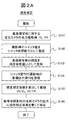
- FIGS. 2A and 2B are flowcharts showing sensitivity correction and luminance value calculation.
- FIG. 2A shows a sensitivity correction routine.
- sensitivity correction is performed using a reference subject (for example, a halogen light source having a constant spectral characteristic) which is fixed at a known position and always has a constant spectral characteristic.
- the sensitivity correction can be performed not only at the time of manufacture but also at a car dealership or the like using a predetermined light source.
- the brightness can be guaranteed by incorporating an LED light source into an emblem on the electric display board or bonnet that provides accurate brightness, it can be implemented even during traveling.
- the image data necessary for the calculation is taken into the sensitivity correction parameter calculation unit 21 and calculated.
- a series of operations are controlled by the control microcomputer 22. The processing contents will be described in the order of steps.
- S101 A reference subject is photographed by the left and right cameras 1a and 1b, and an output value of a specific pixel in the photographed image data is acquired. Let these values be YL and YR.
- the output values YL and YR may be, for example, an average value of a plurality of pixels in captured image data.
- information from the image processing unit 3 may be used to select a specific pixel area in the image data, and calculation may be performed from that area.
- S102 The shutter value at the time of shooting is registered in the register 19 as the shutter reference value T0.
- S103 The luminance value of the reference subject is registered in the register 19 as the luminance reference value L0.
- the specific subject to be a reference such as a halogen light source is used as the reference subject, the luminance of the subject is known.
- S104 When the reference subject of the luminance value L0 is imaged with the shutter value T0, the value to be output is registered in the register 19 as the target output value Y0.
- S105 The sensitivity correction coefficients (Y0 / YL) and (Y0 / YR) for causing the output values YL and YR of the left and right cameras 1a and 1b to become the target output value Y0 are calculated and registered in the register 19.
- the sensitivity correction units 5a and 5b multiply the outputs obtained from the cameras 1a and 1b by the sensitivity correction coefficients (Y0 / YL) and (Y0 / YR) registered in the register 19. , Output sensitivity-corrected image data.
- FIG. 2B shows a luminance value calculation routine.
- the control microcomputer (luminance calculation unit) 22 calculates an accurate luminance value to be used for detection of an object or the like from the corrected output image data.
- S111 The shutter reference value T0 registered in the register 19 in S102 is read.
- S112 The luminance reference value L0 registered in the register 19 in S103 is read.
- S113 The target output value Y0 registered in the register 19 in S104 is read.
- FIG. 3 is a graph for explaining the sensitivity correction method and the luminance value calculation method of the present embodiment.
- the vertical axis represents the output gradation (output value) Y of the camera
- the horizontal axis represents the product of the luminance value L of the subject and the shutter value T.
- the horizontal axis represents the total amount of light from the subject
- the inclination of the graph represents the sensitivity characteristic of the camera.
- the sensitivity characteristics of the cameras 1a and 1b are indicated by solid lines 30a and 30b.
- correction is performed such that the output values YL and YR when the reference subject with the luminance value L0 is photographed with the shutter value T0 become the target output value Y0.
- the sensitivity characteristic after correction is indicated by a broken line 31.
- the sensitivities of the left and right cameras in the stereo camera are respectively corrected, and the corrected camera output values are accurately calculated by the common brightness formula using the parameters T0, L0, and Y0. It can be converted to a value.
- the parameters T0, L0 and Y0 may be set and registered for each pair of left and right cameras. Thereby, absolute accuracy can be secured with respect to the luminance value of the subject to be calculated.
- sensitivity correction between the left and right cameras in a stereo camera will be described. Although there is a phenomenon that the dynamic range and the maximum saturation output decrease due to the sensitivity correction, in the present embodiment, these performance deteriorations are minimized.
- FIG. 4 is a diagram for explaining the performance deterioration associated with the sensitivity correction.
- the horizontal axis is the product of the subject brightness value and the shutter value, and represents the sum of the light quantity from the subject.
- the vertical axis represents the output tone of the camera, and the slope of the graph represents the sensitivity characteristic of the camera.
- the sensitivity characteristic before correction is shown by a solid line 40 for one camera.
- a target characteristic in the case of correction to a higher sensitivity (correction 1) is indicated by a broken line 41
- a target characteristic in a case of correction to a lower sensitivity (correction 2) is indicated by a broken line 42.
- the camera identifies the brightness
- the dynamic range which is a possible range, decreases from the position 45 to the position 46.
- the amount of decrease of the dynamic range depends on the amount of correction. Since the camera characteristics before correction are dispersed, cameras with different dynamic ranges are mixed together with the sensitivity correction.
- the maximum saturation output 43 of the characteristics before correction is determined, so the maximum saturation output after correction drops to the level of reference numeral 44.
- the reduction of the maximum saturated output depends on the amount of correction. Since the camera characteristics before correction are dispersed, cameras with different maximum saturated output are mixed with the sensitivity correction.
- the phenomenon that the dynamic range or the maximum saturation output decreases due to the sensitivity correction is accompanied.
- the image processing unit 3 can not calculate an accurate distance to the subject, and is not suitable as a stereo camera for automatic driving. Therefore, priority is given to suppressing the decrease of the maximum saturation output over the decrease of the dynamic range accompanying the sensitivity correction, and the method (correction 1) of correcting to the one with the higher sensitivity is selected.
- amendment 1) to correct
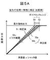
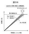
- 5A and 5B are diagrams for explaining sensitivity correction among a plurality of cameras, and show a sensitivity correction method for minimizing performance deterioration.
- the sensitivity characteristics 50a and 50b before correction of the left and right cameras 1a and 1b used in the stereo camera and the range 50c of the sensitivity variation of all the cameras are shown.
- the pre-correction sensitivity 50a of the camera 1a is higher than the pre-correction sensitivity 50b of the camera 1b.
- FIG. 5A shows a case (comparative example) in which the characteristics of all the cameras are corrected to the same characteristics.
- the corrected target characteristic 51 is set to the characteristic of the maximum sensitivity in the range 50c of the sensitivity variation.
- the amount of decrease in the dynamic range of the camera is greatly increased.
- the dynamic range of the pre-correction sensitivity 50b decreases from the position 52 to the position 54.
- FIG. 5B shows the case of correcting to the characteristic of higher sensitivity in the left and right cameras 1a and 1b (this embodiment).
- the sensitivity 50a of the camera 1a since the sensitivity 50a of the camera 1a is high, the corrected target characteristic 51 'is set to the sensitivity 50a. Therefore, the sensitivity 50b of the camera 1b may be matched to the sensitivity 50a of the camera 1a.
- the correction amount in this case may be only the difference in sensitivity between the pair of left and right cameras 1a and 1b.
- the dynamic range of the pre-correction sensitivity 50b (camera 1b) can be minimized by reducing the dynamic range from the position 52 to the position 53 only.
- the registration method of parameters used in the calculation of the luminance value is different.
- the shutter reference value T0, the luminance reference value L0, and the target output value Y0 are registered in the same value in all the cameras.
- the shutter reference value T0 and the luminance reference value L0 individually register the same value for all the cameras, and the target output value Y0 individually for each set of cameras.
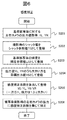
- FIG. 6 is a diagram showing a flowchart of sensitivity correction in the present embodiment. As described in FIG. 5B, correction is made to the characteristic of the higher sensitivity by the left and right cameras 1a and 1b.
- S201 to S203 Acquire the output values YL and YR of a specific pixel in the captured image data of the reference subject, set the shutter value at the time of shooting as the shutter reference value T0, and register the brightness of the reference subject as the brightness reference value L0 in the register 19. Do. These are the same as S101 to S103 in FIG. 2A.
- S204 The larger one of the output values YL and YR of the left and right cameras is registered in the register 19 as the target output value Y0.
- the target output value Y0 is registered as an individual value for each camera that is a set.
- S205 The sensitivity correction coefficients (Y0 / YL) and (Y0 / YR) for causing the output values YL and YR of the left and right cameras 1a and 1b to become the target output value Y0 are calculated and registered in the register 19. Since one of the output values YL and YR matches Y0, the correction coefficient is 1 and the other correction coefficient is a value larger than 1 (correction for increasing the sensitivity).
- the sensitivity correction units 5a and 5b multiply the outputs from the cameras 1a and 1b by the sensitivity correction coefficients (Y0 / YL) and (Y0 / YR) registered in the register 19 to obtain the sensitivity. Output corrected image data.
- the luminance value calculation routine is the same as that shown in FIG. However, the value of the target output value Y0 read out in S113 is different in that the cameras are individually registered.
- the sensitivity of the left and right cameras in the stereo camera is corrected in accordance with the higher sensitivity, it is possible to minimize the decrease in the dynamic range due to the sensitivity correction.
- FIG. 7 is a diagram showing an entire configuration of a stereo camera system according to a third embodiment.
- the same parts as in the first embodiment (FIG. 1) are assigned the same reference numerals and explanation thereof is omitted.
- a color image sensor is used for the imaging units 11a and 11b.
- color processing units 23 a and 23 b are added to the calibration circuit unit 2, and a color labeling calculation unit 24 is added to the image processing unit 3.
- the sensitivity correction units 5a and 5b of the calibration circuit unit 2 are for red (R), green (G), and blue (B) color data. Perform sensitivity correction.
- the ratio of each color output of the camera when the specified predetermined light source is photographed, that is, the color balance is determined to be a predetermined value.
- sensitivity correction is performed so that the ratio of red to green (R / G) and the ratio of blue to green (B / G) become predetermined values.
- processing such as demosaicing (complementing processing using adjacent pixel values) is performed on the imaging elements having the Bayer arrangement.
- the parallax calculation unit 7 calculates the parallax of the image data of the left and right two systems sent to the image processing unit 3 and the edge calculation unit 8 performs the edge calculation of the image data of any one left and right system. . Further, in the color labeling calculation unit 24, each coordinate position is allocated to the numerical value labeled on the color space.
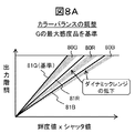
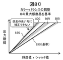
- FIGS. 8A to 8C are diagrams for explaining sensitivity correction including adjustment of color balance.
- the color balance is further adjusted on the premise that the camera sensitivity is corrected to the highest sensitivity characteristic. At that time, it is shown that the case where the performance deterioration due to the sensitivity correction is further increased or the case where the sensitivity correction can not be performed occurs.
- FIGS. 8A to 8C it is assumed that the sensitivity variation ranges of the respective colors (R, G, B) are in the states indicated by reference numerals 80R, 80G, and 80B, respectively.
- FIG. 8A shows the case where color balance adjustment is performed based on the green (G) maximum sensitivity product. That is, the target sensitivity characteristic 81G of G is the maximum sensitivity of the sensitivity variation range 80G of G.
- the target sensitivity characteristics 81R and 81B for R and B are the target sensitivity characteristics 81G for G multiplied by predetermined color balance values (R / G and B / G).
- the maximum sensitivity products of R and B are smaller than the target sensitivity characteristics 81R, 81B of R and B
- the variation width is used for the sensitivity correction of R and B. It will be over-compensated over. That is, the decrease in dynamic range is increased.
- FIG. 8B shows a case where color balance adjustment is performed based on the red (R) maximum sensitivity product. That is, the target sensitivity characteristic 82R of R is the maximum sensitivity of the sensitivity variation range 80G of R.
- the G target sensitivity characteristic 82G is included in the G sensitivity variation range 80G. At this time, a camera having a sensitivity higher than that of the G target sensitivity characteristic 82G can not be corrected to a higher sensitivity. Therefore, correction has to be made to the lower sensitivity side, and as described in FIG. 4, the maximum saturated output is reduced.
- FIG. 8C shows the case where color balance adjustment is performed on the basis of the blue (B) maximum sensitivity product. Also in this case, the target sensitivity characteristic 83G of G is included in the sensitivity variation range 80G of G by adjusting the color balance, but for a camera whose sensitivity is larger than the target sensitivity characteristic 83G of G, the sensitivity is higher. It can not be corrected. Therefore, as a result of correction to the lower sensitivity side, the maximum saturated output is reduced.
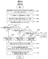
- FIG. 9A shows a sensitivity correction routine.
- S301 The output value of each of the RGB colors of the specific pixel in the captured image data of the reference subject by the left and right cameras 1a and 1b is acquired. Let these values be (R1, G1, B1), (R2, G2, B2). As this output value, a plurality of pixels in captured image data may be averaged for each color. Further, information from the image processing unit 3 may be used to select a specific pixel area in the image data, and calculation may be performed for each color from that area.
- S302 The shutter value at the time of shooting is registered in the register 19 as the shutter reference value T0.
- S303 The luminance value of the reference subject is registered in the register 19 as the luminance reference value L0.
- S304 The output values of the left and right cameras for each color are compared, and the larger value is taken as (Rmax, Gmax, Bmax).
- S305 It is determined by equation (1) whether it is the minimum correction to correct R and B based on Gmax. If the formula (1) is satisfied, the process proceeds to step S306, and if not, the process proceeds to step S307.
- S307 It is determined by equation (3) whether or not the correction of R and G is the minimum correction with reference to Bmax. If the formula (3) is satisfied, the process proceeds to step S308, and if not, the process proceeds to step S309.
- R0 (. Alpha./.beta.)Bmax
- G0 (1 / .beta.) Bmax
- B0 Bmax (4).
- S309 It is determined by equation (5) whether it is the minimum correction to correct B and G based on Rmax. If the expression (5) is satisfied, the process proceeds to step S310. If the expression is not satisfied, an error is generated in step S311, and the process ends.
- S312 The calculated target output values (R0, G0, B0) are registered in a register.
- S313 Sensitivity correction coefficients (R0 / R1, G0) for the output values (R1, G1, B1), (R2, G2, B2) of the left and right cameras 1a, 1b to become target output values (R0, G0, B0) Calculate / G1, B0 / B1), (R0 / R2, G0 / G2, B0 / B2), and register them in the register 19.
- the sensitivity correction units 5a and 5b set the sensitivity correction coefficients (R0 / R1, G0 / G1, B0 / B1) registered in the register 19 to the outputs from the cameras 1a and 1b, (R0 / R2, G0 / G2, B0 / B2) are multiplied, and the image data subjected to sensitivity correction is output.
- FIG. 9B shows a luminance value calculation routine.
- S321 The shutter reference value T0 registered in the register 19 in S302 is read.
- S322 The luminance reference value L0 registered in the register 19 in S303 is read.
- S323 The target output values (R0, G0, B0) registered in the register 19 in S312 are read out.
- S324 The corrected image output values (R (i, j), G (i, j), B (i, j)) and the shutter value T at the time of shooting are acquired.
- S325 Using the parameters L0, R0, G0, B0, T0 and T, the accurate luminance distributions L (R), L (G) and L (B) for R, G and B are calculated by the following equations. From this, the chromaticity value can be determined.
- L (R) R (i, j) * (L0 / R0) * (T0 / T)
- L (G) G (i, j) * (L0 / G0) * (T0 / T)
- L (B) B (i, j) * (L0 / B0) * (T0 / T).
- the sensitivity characteristics of the left and right cameras are corrected to the higher sensitivity for any color while maintaining the color balance of R, G and B at predetermined values, and the chromaticity value together with the accurate luminance distribution of the object Can be calculated.
- the third embodiment in the sensitivity correction of the left and right cameras in the stereo camera, it is possible to minimize the reduction of the dynamic range due to the sensitivity correction while maintaining the color balance at a predetermined value. In addition, absolute accuracy can be ensured with respect to the luminance value (chromaticity value) of each color of the subject to be calculated.
- a stereo camera system having two cameras has been described as an example, but the present invention is not limited to this, and a multi-view camera and a multi-viewpoint using two or more cameras. The same applies to cameras.
- 1a, 1b Camera
- 2 Calibration circuit unit
- 3 Image processing unit
- 4 recognition application unit
- 5a, 5b sensitivity correction unit
- 6a, 6b geometric correction unit
- 7 disparity calculation unit
- 8 Edge calculation unit
- 11a, 11b imaging unit
- 13a, 13b AD converter
- 19 20: register (storage unit)
- 21 Sensitivity correction parameter calculation unit
- 22 Control microcomputer (brightness calculation unit)
- 23a, 23b color processing unit
- 24 Color labeling calculation unit
- 100 Imaging device.
Landscapes
- Engineering & Computer Science (AREA)
- Multimedia (AREA)
- Signal Processing (AREA)
- Physics & Mathematics (AREA)
- Remote Sensing (AREA)
- Radar, Positioning & Navigation (AREA)
- General Physics & Mathematics (AREA)
- Electromagnetism (AREA)
- Human Computer Interaction (AREA)
- Automation & Control Theory (AREA)
- Measurement Of Optical Distance (AREA)
- Studio Devices (AREA)
- Color Television Image Signal Generators (AREA)
- Processing Of Color Television Signals (AREA)
- Length Measuring Devices By Optical Means (AREA)
Abstract
本発明は、被写体の輝度や色度の測定精度を確保しつつ、感度補正に伴う性能劣化を最小化するための撮像装置を提供する。撮像装置100は、少なくとも2つの撮像部11の感度特性が同一になるように補正する感度補正部5と、感度補正部5における補正パラメータを記憶する記憶部19と、記憶部19に記憶した補正パラメータと撮像部11のシャッタ値に基づいて被写体の輝度値を算出する輝度算出部22と、を備える。ここに感度補正部5は、少なくとも2つの撮像部11の感度特性を、感度が最も高い撮像部の感度特性に一致するように補正する。さらに感度補正部5は、各色に対する感度特性が所定の比になるように補正するとともに、輝度算出部22は、被写体の各色に対する輝度値を算出する。
Description
本発明は、複数の撮像部を有する撮像装置およびその調整方法に係り、特に複数の撮像部間の感度特性の補正に関する。
近年、車両に搭載したカメラやレーダを使って、道路や周辺の歩行者や車両を検出し、運転者にとって危険かどうかを判断するITS(Intelligent Transport Systems:高度道路交通システム)技術の開発が進められている。また、高速道路や自動車専用道路での使用が前提のACC(Adaptive Cruise Control:定速走行・車間距離制御装置)や自動ブレーキなどの運転支援システムでは、車両検出に適し、耐候性に優れたミリ波レーダが用いられている。しかし、より高度な機能が要求される自動運転になると、周囲の道路構造や歩行者などの検出が必要となり、高い空間分解能を持った距離情報が得られるステレオカメラが有望となる。
ステレオカメラでは、視点の異なる2台のカメラで撮像した物体の2枚の画像上の位置の違い(視差)と2台のカメラの間隔(基線長)とカメラの焦点距離などから三角測量の原理を用いて距離が計測される。視差は、左右2台のカメラの左右画像の局所領域での一致の程度から求める。そのため、2台のカメラの特性は極力一致している必要があり、特性差が大きいと視差を求めるのが難しくなる。
このため、カメラ毎のゲイン補正量やオフセット補正量などの補正量を製造時に予め測定し、ルックアップテーブル(LUT)としてROMに格納し、出荷後はルックアップテーブル(LUT)を参照して補正する技術が開示されている(例えば特許文献1)。
自動運転では、交通信号機や路面マークも検出するため、カラー情報を利用する。交通信号機や尾灯・制動灯などの明るさや色は、交通法規や規格等で定められ、計測器で測定される輝度や色度などの物理量で規定されている。これを手掛かりに対象物を検出する場合、カメラの特性、特に感度特性は左右の特性一致だけでなく、製品間の個体差に依存せずに全ての出荷製品で同一の特性であること(絶対精度)が求められ、感度特性を補正する技術は重要となる。
ところが感度特性の補正では、補正量に応じて、ダイナミックレンジの低下や最大飽和出力(出力階調)の低下といった性能劣化を伴う。さらに、カラーCMOSセンサーやカラーCCDなどのカラー撮像素子の感度特性は、フォトダイオードの特性バラツキだけでなく、コンバージョン容量やアンプ回路などの半導体起因のバラツキや、カラーフィルタの膜厚分布や色素バラツキなどカラーフィルタ要因のバラツキの影響を受ける。また、撮像素子以外にレンズ、偏光フィルタや赤外カットフィルタなどの光学フィルタの透過率もばらつく。その結果、感度特性のバラツキが拡大してその補正が十分になされないと、要求性能を満足できないカメラが発生する。
さらには、色判定による検出を行うためにカメラの色毎の感度の比(カラーバランス)である赤と緑の比(R/G)や青と緑の比(B/G)が決まっているため、カラーバランスを満足するような補正が必要になる。
このようなカメラ毎の特性バラツキの増加傾向に対して、前記特許文献1をはじめ従来技術では、出荷するカメラ製品全ての感度特性を一律の特性に一致させるように補正するものであり、製造歩留りが上がらず製造コストを増大させるという課題があった。
本発明の目的は、被写体の輝度や色度の絶対精度を確保しつつ、感度補正に伴う性能劣化を最小化するための撮像装置およびその調整方法を提供することである。
本発明の撮像装置は、少なくとも2つの撮像部の感度特性が同一になるように補正する感度補正部と、感度補正部における補正パラメータを記憶する記憶部と、記憶部に記憶した補正パラメータと撮像部のシャッタ値に基づいて被写体の輝度値を算出する輝度算出部と、を備える。ここに感度補正部は、少なくとも2つの撮像部の感度特性を、感度が最も高い撮像部の感度特性に一致するように補正する。さらに感度補正部は、各色に対する感度特性が所定の比になるように補正するとともに、輝度算出部は、被写体の各色に対する輝度値を算出する。
本発明によれば、感度補正による性能劣化を大幅に抑制するとともに、被写体の輝度や色度の絶対精度を確保できる高性能の撮像装置およびその調整方法を実現できる。
以下、本発明の実施の形態を図面を参照して説明する。以下の実施例では、2台のカメラを有するステレオカメラシステムを例に説明するが、本発明は、2台以上の複数のカメラを有するシステムにも同様に適用できる。
実施例1では、ステレオカメラにおいて、1台のカメラ毎に行う感度補正について説明する。
図1は、実施例1に係るステレオカメラシステムの全体構成を示す図である。ステレオカメラシステムは、左右の2台のカメラ1a,1b、キャリブレーション回路部2、画像処理部3、認識アプリケーション部4、感度補正パラメータ計算部21、及び制御マイコン22を備えている。このうち、カメラ1a,1bと、キャリブレーション回路部2、感度補正パラメータ計算部21、及び制御マイコン22が撮像装置100を構成する。
左右のカメラ1a,1bは、互いに光軸が平行になるように、また2台が所定の距離になるように筐体(図示せず)に固定されている。カメラ1a,1bからの出力画像データは、キャリブレーション回路部2の感度補正部5a、5bにて、撮像素子の感度バラツキやレンズの透過率バラツキに起因する感度バラツキを補正する。また幾何補正部6a,6bにて、レンズの歪などの幾何学的な補正を行う。さらに、画像処理部3の視差計算部7にてステレオマッチングによる距離画像を計算し、エッジ計算部8にてエッジ画像を生成する。画像処理部3で生成した距離画像データやエッジ画像データは、認識アプリケーション部4へ送られ、人物検出・車両検知・信号灯検知などの画像認識が行われる。以下、各部の動作を説明する。
左右のカメラ1a,1bは、それぞれレンズ9a,9b、CMOSイメージセンサIC10a,10bで構成されている。レンズ9a,9bは被写体からの光を集光し、CMOSイメージセンサIC10a,10bの撮像部11a,11bの撮像面に像を結像する。CMOSイメージセンサICは、フォトダイオードアレイからなる撮像部11a,11b、ゲインアンプ12a,12b、AD変換器13a,13b、信号処理回路14a,14b、出力回路15a,15b、撮像部駆動回路16a,16b、タイミングコントローラ17a,17bなどが半導体チップ上に実装されている。
レンズ9a,9bにより撮像部11a,11bの撮像面に結像した光信号は、アナログ電気信号に変換され、ゲインアンプ12a,12bで所定な電圧に増幅され、AD変換器13a,13bによって、アナログ画像信号から所定の輝度階調(例えば1024階調のグレースケール)のデジタル信号に変換される。そして、信号処理回路14a,14bで処理された後、出力回路15a,15bから出力される。
カメラ1a,1bのシャッタ値やゲインアンプ12a,12bなどの設定は、レジスタ18a,18bを介して、制御マイコン22から設定する。また左右のカメラ1a,1bは、レジスタ18a,18bとタイミングコントローラ17a,17bにより同期して動作する。
キャリブレーション回路部2で使用する補正用パラメータは、制御マイコン22からレジスタ19を経由して送られる。レジスタ(記憶部)19には、補正用パラメータが登録されている。キャリブレーション回路部2で補正された画像データは、画像処理部3と感度補正パラメータ計算部21に出力される。制御マイコン22は、キャリブレーション回路部2で補正された画像データに基づき、輝度値の算出を行う輝度算出部の機能を有している。
画像処理部3に送られた左右2系統の画像データは、視差計算部7にて、視差を算出するマッチング処理が行われ、マッチング処理された画像上の対象物の距離は、三角法の原理で計算される。ここで、正確な距離を計算するためには、キャリブレーション回路部2で精度の高い補正を実施する必要があり、補正が十分でないとミスマッチが発生し、正確な距離が算出できなくなる。また左右いずれか1系統の画像データは、エッジ計算部8でエッジ計算が実施され、エッジ画像が出力される。
画像処理部3と感度補正パラメータ計算部21との間で必要な情報のやり取りは、レジスタ20経由で制御マイコン22により行われる。以下、感度補正パラメータ計算部21による、感度補正処理および正確な輝度値算出におけるパラメータ設定について説明する。
図2Aと図2Bは、感度補正および輝度値算出のフローチャートを示す図である。まず図2Aは感度補正ルーチンを示す。このルーチンでは、左右のカメラ1a,1bに対し、既知の位置に固定され、常に分光特性が一定な基準被写体(例えば分光特性が一定なハロゲン光源など)を用いて感度補正を行う。感度補正は製造時だけでなく、カーディーラーなどにおいても、所定の光源を用いて実施可能である。また、正確な輝度を出す電光表示板やボンネット上のエンブレムにLED光源を組み込むなどにより輝度が保証可能であれば、走行時でも実施可能である。計算に必要な画像データは、感度補正パラメータ計算部21に取り込まれて計算される。一連の動作は制御マイコン22によって制御される。ステップ順に処理内容を説明する。
S101:左右のカメラ1a,1bにより基準被写体を撮影し、撮像画像データ内の特定画素の出力値を取得する。この値をYL,YRとする。出力値YL,YRは、撮像画像データ内の複数の画素の平均値などであってもよい。また、画像処理部3からの情報を利用し、画像データ内の特定の画素領域を選び出し、その領域から計算してもよい。
S102:撮影時のシャッタ値をシャッタ参照値T0としてレジスタ19に登録する。S103:基準被写体の輝度値を輝度参照値L0としてレジスタ19に登録する。このルーチンでは、基準被写体としてハロゲン光源などの基準となる特定の被写体を用いているので、被写体の輝度は既知である。
S104:輝度値L0の基準被写体をシャッタ値T0で撮像した場合、出力したい値を目標出力値Y0としてレジスタ19に登録する。S105:左右のカメラ1a,1bの出力値YL,YRが目標出力値Y0となるための感度補正係数(Y0/YL),(Y0/YR)を算出し、レジスタ19に登録する。
S106:実際の被写体撮影時は、感度補正部5a,5bは、カメラ1a,1bから得られた出力にレジスタ19に登録された感度補正係数(Y0/YL),(Y0/YR)を乗じて、感度補正された画像データを出力する。
図2Bは輝度値算出ルーチンを示す。このルーチンでは、制御マイコン(輝度算出部)22により、補正された出力画像データから対象物の検知などに使用する正確な輝度値を算出する。
S111:前記S102でレジスタ19に登録したシャッタ参照値T0を読み出す。S112:前記S103でレジスタ19に登録した輝度参照値L0を読み出す。S113:前記S104でレジスタ19に登録した目標出力値Y0を読み出す。
S114:補正後の画像出力値の分布Y1(i,j)と撮影時のシャッタ値T1を取得する。S115:パラメータL0,Y0,T0,T1を用いて、次式により画像の輝度分布L1(i,j)を計算する。
L1(i,j)=Y1(i,j)*(L0/Y0)*(T0/T1)
これにより、被写体の輝度を高精度に求めることができる。
L1(i,j)=Y1(i,j)*(L0/Y0)*(T0/T1)
これにより、被写体の輝度を高精度に求めることができる。
図3は、本実施例の感度補正法および輝度値算出法をグラフで説明する図である。縦軸にカメラの出力階調(出力値)Y、横軸に被写体の輝度値Lとシャッタ値Tとの積を示している。横軸は被写体からの光量の総和を表しており、グラフの傾きはカメラの感度特性を表す。例えば、カメラ1a,1bの感度特性が実線30a,30bで示されるものだったとする。感度補正では、輝度値L0の基準被写体をシャッタ値T0で撮影したときの出力値YL,YRが、目標出力値Y0になるよう補正を行う。補正後の感度特性を破線31で示す。
補正後の感度特性31の直線部の傾きk=Y0/(L0*T0)は、補正後の感度を表す。この関係を使って、任意の被写体をシャッタ値T1で撮影したときの出力階調がY1であったときの輝度値は、L1=Y1/(k*T1)で求められる。すなわち、シャッタ参照値T0と輝度参照値L0における目標出力値Y0を登録しておけば、任意の輝度を持つ被写体における出力値Y1から正確な輝度値L1を算出することができる。
このように実施例1によれば、ステレオカメラにおける左右のカメラの感度をそれぞれ補正し、補正後のカメラ出力値は、パラメータT0,L0,Y0を用いた共通の輝度計算式により、正確な輝度値に変換することができる。その場合、パラメータT0,L0,Y0は、左右のカメラの組毎に設定し、登録すればよい。これにより、算出する被写体の輝度値に関し絶対精度を確保することができる。
実施例2では、ステレオカメラにおける左右のカメラ間の感度補正について説明する。感度補正によりダイナミックレンジや最大飽和出力が低下する現象が伴うが、本実施例ではこれらの性能劣化を最小化させるようにした。
図4は、感度補正に伴う性能低下を説明する図である。横軸は被写体輝度値とシャッタ値との積であり、被写体からの光量の総和を表す。縦軸はカメラの出力階調を示し、グラフの傾きはカメラの感度特性を表す。ここでは1台のカメラについて、補正前の感度特性を実線40で示す。補正の仕方として、感度が高い方に補正する場合(補正1)の目標特性を破線41で示し、感度の低い方に補正する場合(補正2)の目標特性を破線42で示す。以下、これらを比較する。
まず、感度の高い方に補正する場合(補正1)では、補正前の特性の最大飽和出力43が決まっているので(AD変換器13a,13bの最大階調値)、カメラにより明るさを識別できる範囲であるダイナミックレンジは、符号45の位置から符号46の位置まで低下する。ダイナミックレンジの低下量は補正量に依存する。補正前のカメラ特性はばらついているので、感度補正に伴い、ダイナミックレンジの異なるカメラが混在することになる。
一方、感度の低い方に補正する場合(補正2)では、補正前の特性の最大飽和出力43が決まっているので、補正後の最大飽和出力は符号44のレベルまで低下する。最大飽和出力の低下は補正量に依存する。補正前のカメラ特性はばらついているので、感度補正に伴い、最大飽和出力の異なるカメラが混在することになる。
このように、感度補正によりダイナミックレンジ又は最大飽和出力が低下する現象が伴う。実用上の観点から言えば、左右のカメラによるステレオマッチング処理を行う場合、左右のカメラの飽和出力が異なると飽和点近傍でのマッチング処理を正常に行うことができなくなる。その結果、画像処理部3において被写体までの正確な距離を算出できなくなり、自動運転用のステレオカメラとしては不適格となる。よって、感度補正に伴うダイナミックレンジの低下よりも最大飽和出力の低下を抑えることを優先させ、感度の高い方に補正する方法(補正1)を選択する。以下では、感度の高い方に補正する方法(補正1)に基づき説明する。
図5Aと図5Bは、複数のカメラ間での感度補正を説明する図であり、性能劣化を最小限に抑える感度補正方法を示す。ステレオカメラで用いる左右のカメラ1a,1bの補正前の感度特性50a,50b、および全てのカメラの感度バラツキの範囲50cを示している。なお、ここではカメラ1aの補正前感度50aがカメラ1bの補正前感度50bよりも高いものとする。
図5Aは、全てのカメラの特性を同一の特性に補正する場合(比較例)を示す。補正後の目標特性51は、感度バラツキの範囲50cで最大感度の特性に設定する。目標特性51に一致させるため、カメラのダイナミックレンジの低下量は大幅に増大する。例えば、補正前感度50b(カメラ1b)のダイナミックレンジは、符号52から符号54の位置まで低下する。
図5Bは、左右のカメラ1a,1b内で感度の高い方の特性に補正する場合(本実施例)である。この例では、カメラ1aの感度50aが高いので、補正後の目標特性51’は感度50aに設定する。よって、カメラ1bの感度50bをカメラ1aの感度50aに一致させればよい。この場合の補正量は、組となる左右のカメラ1a,1bの感度差分だけで済む。補正前感度50b(カメラ1b)のダイナミックレンジは、符号52から符号53の位置に低下するだけで、ダイナミックレンジの低下を最小限に抑制することができる。
なお、上記した感度補正の違いに伴い、輝度値算出で用いるパラメータの登録方法が異なる。図5Aの場合は、シャッタ参照値T0と輝度参照値L0と目標出力値Y0を全てのカメラで同じ値を登録する。これに対し図5Bの場合には、シャッタ参照値T0と輝度参照値L0は全てのカメラで同じ値を、目標出力値Y0は組となるカメラ毎に個別に登録する。
図6は、本実施例における感度補正のフローチャートを示す図である。図5Bで説明したように、左右のカメラ1a,1bで感度の高い方の特性に補正する。
S201~S203:基準被写体の撮像画像データ内の特定画素の出力値YL、YRを取得し、撮影時のシャッタ値をシャッタ参照値T0とし、基準被写体の輝度を輝度参照値L0としてレジスタ19に登録する。これらは、図2AのS101~S103と同じである。
S204:左右のカメラの出力値YL,YRのうち大きい値の方を、目標出力値Y0としてレジスタ19に登録する。この目標出力値Y0は、組となるカメラ毎に個別の値として登録する。
S205:左右のカメラ1a,1bの出力値YL,YRが目標出力値Y0となるための感度補正係数(Y0/YL),(Y0/YR)を算出し、レジスタ19に登録する。出力値YL,YRのいずれか一方はY0と一致しているので、その補正係数は1になり、他方の補正係数は1より大きい値(感度を高くする補正)になる。
S206:実際の被写体撮影時は、感度補正部5a,5bは、カメラ1a,1bからの出力にレジスタ19に登録された感度補正係数(Y0/YL),(Y0/YR)を乗じて、感度補正された画像データを出力する。
輝度値算出のルーチンは、図2Bと同様であり説明を省略する。ただし、S113で読み出す目標出力値Y0の値は、カメラ個別に登録されている点で異なっている。
実施例2によれば、ステレオカメラにおける左右のカメラの感度を、感度の高い方に合わせて補正するようにしたので、感度補正によるダイナミックレンジの低下を最小限に抑制することができる。
実施例3では、ステレオカメラにおける左右のカメラ間の感度補正において、さらにカラーバランスの調整を行う場合について説明する。
図7は、実施例3に係るステレオカメラシステムの全体構成を示す図である。実施例1(図1)と同一部分については同一符号を付して説明を省略する。図1の構成において、撮像部11a,11bにはカラーイメージセンサを使用している。また、キャリブレーション回路部2にはカラー処理部23a,23bを、画像処理部3には、カラーラベリング計算部24を追加している。
左右のカメラ1a,1bから出力されるカラー画像データに対し、キャリブレーション回路部2の感度補正部5a,5bは、赤(R)、緑(G)、青(B)の各色データに対して感度補正を実施する。カラー画像の出力では、規定された所定の光源を撮影したときのカメラの各色出力の比、すなわちカラーバランスが所定の値になるよう定められている。具体的には、赤と緑の比(R/G)と、青と緑の比(B/G)が所定の値になるように、感度補正を実施する。カラー処理部23a,23bでは、ベイヤー配列をした撮像素子に対し、デモザイキング(隣接画素値を用いた補完処理)などの処理を実施する。
画像処理部3に送られた左右2系統の画像データは、視差計算部7にて視差が計算され、また左右いずれか1系統の画像データは、エッジ計算部8にてエッジ計算が実施される。さらにカラーラベリング計算部24では、各座標位置を色空間上でラベリングされた数値に割り付けられる。
図8A~図8Cは、カラーバランスの調整を含む感度補正を説明する図である。カメラの感度を最も感度の高い特性に補正することを前提に、さらにカラーバランスの調整を実施する。その際、感度補正による性能低下がさらに大きくなるケース、あるいは感度補正ができないケースが発生することを示す。いずれのケースになるかは、補正対象となる全てのカメラについて、赤(R)、緑(G)、青(B)の各色の感度バラツキの状態と、所望するカラーバランスR/G、B/Gの値の関係で異なってくる。図8A~図8Cにおいて、各色(R,G,B)の感度バラツキ範囲が、それぞれ符号80R,80G,80Bで示す状態であると仮定する。
図8Aは、緑(G)の最大感度品を基準にカラーバランス調整を行う場合を示す。すなわち、Gの目標感度特性81Gは、Gの感度バラツキ範囲80Gの最大感度とする。これに対しカラーバランスの調整を行うため、RとBの目標感度特性81R,81Bは、Gの目標感度特性81Gに所定のカラーバランス値(R/G,B/G)を掛けたものとする。その際、RとBの最大感度品(感度バラツキ範囲80R,80Bの最大感度)が、RとBの目標感度特性81R,81Bよりも小さい場合、RとBの感度補正については、バラツキ幅を越えての過剰な補正をすることになる。すなわち、ダイナミックレンジの低下が増大することになる。
一方図8Bは、赤(R)の最大感度品を基準にカラーバランス調整を行う場合を示す。すなわち、Rの目標感度特性82Rは、Rの感度バラツキ範囲80Gの最大感度とする。これに対してカラーバランスの調整を行うと、Gの目標感度特性82GはGの感度バラツキ範囲80Gに含まれる。その際、Gの目標感度特性82Gよりも感度が大きいカメラについては、感度の高い方に補正することができない。従って、感度の低い方に補正せざるを得ず、図4で述べたように、最大飽和出力の低下を招くことになる。
図8Cは、青(B)の最大感度品を基準にカラーバランス調整を行う場合を示す。この場合も同様で、カラーバランスの調整により、Gの目標感度特性83GはGの感度バラツキ範囲80Gに含まれるが、Gの目標感度特性83Gよりも感度が大きいカメラについては、感度の高い方に補正することができない。従って、感度の低い方に補正する結果、最大飽和出力の低下を招くことになる。
このように、カラーバランスの調整を含む感度補正を行うと、調整時に基準とする色以外の色に関して、ダイナミックレンジの低下が増大する、あるいは、最大飽和出力の低下を招く、のいずれかのケースが発生する。前述したように、実用的には最大飽和出力の低下を抑えることが有利であることから、図8Bや図8Cのように感度の高い方に補正できないケースを避けるようにする。つまり、図8Aのように、どの色に関しても感度の高い方に補正できる方法を採用する。以下、このような感度補正を、補正量を最小化させるという意味で「最小補正」と呼ぶことにする。最小補正を実現するには、R,G,Bの感度バラツキ状況に応じて、どの色を基準に感度補正を行えばよいかを判定する必要がある。次に、カラーバランスと最小補正を両立する補正方法を説明する。
図9Aと図9Bは、本実施例における感度補正と輝度値算出のフローチャートを示す図である。なお、カラーバランスの値は、R/G=α、B/G=βとなるように、予め定められているものとする。
まず図9Aは感度補正ルーチンを示す。S301:左右のカメラ1a,1bによる、基準被写体の撮像画像データ内の特定画素のRGB色毎の出力値を取得する。この値を(R1,G1,B1),(R2,G2,B2)とする。この出力値として、撮像画像データ内の複数の画素をそれぞれの色毎に平均値などをとってもよい。また画像処理部3からの情報を利用し、画像データ内の特定の画素領域を選び出し、その領域から色毎に計算してもよい。
S302:撮影時のシャッタ値をシャッタ参照値T0としてレジスタ19に登録する。S303:基準被写体の輝度値を輝度参照値L0としてレジスタ19に登録する。S304:左右のカメラの各色についての出力値を比較し、大きい方の値を(Rmax,Gmax,Bmax)とする。
S305~S311では、どの色を基準にカラーバランスを取れば良いかを判定する。ここで用いる判定式は、図8Aのように、基準色以外の色に関して、感度の高い方に補正すること(最小補正)を実現するための条件である。
S305:Gmaxを基準としてRとBを補正するのが最小補正かどうかを(1)式により判定する。(1)式を満足すればS306へ進み、満足しなければS307へ進む。S306:目標出力値(R0,G0,B0)を(2)式で算出する。
Rmax/Gmax<α、かつ、Bmax/Gmax<β (1)
R0=α*Gmax,G0=Gmax,B0=β*Gmax (2)。
Rmax/Gmax<α、かつ、Bmax/Gmax<β (1)
R0=α*Gmax,G0=Gmax,B0=β*Gmax (2)。
S307:Bmaxを基準としてRとGを補正するのが最小補正かどうかを(3)式により判定する。(3)式を満足すればS308へ進み、満足しなければS309へ進む。S308:目標出力値(R0,G0,B0)を(4)式で算出する。
Rmax/Bmax<α/β、かつ、Gmax/Bmax<1/β (3)
R0=(α/β)Bmax,G0=(1/β)Bmax,B0=Bmax (4)。
Rmax/Bmax<α/β、かつ、Gmax/Bmax<1/β (3)
R0=(α/β)Bmax,G0=(1/β)Bmax,B0=Bmax (4)。
S309:Rmaxを基準としてBとGを補正するのが最小補正かどうかを(5)式により判定する。(5)式を満足すればS310へ進み、満足しなければS311にてエラー発生として処理を終了する。S310:目標出力値(R0,G0,B0)を(6)式で算出する。
Gmax/Rmax<1/α、かつ、Bmax/Rmax<β/α (5)
R0=Rmax,G0=(1/α)Rmax,B0=(β/α)Rmax (6)。
Gmax/Rmax<1/α、かつ、Bmax/Rmax<β/α (5)
R0=Rmax,G0=(1/α)Rmax,B0=(β/α)Rmax (6)。
S312:算出した目標出力値(R0,G0,B0)をレジスタに登録する。S313:左右のカメラ1a,1bの出力値(R1,G1,B1),(R2,G2,B2)が目標出力値(R0,G0,B0)となるための感度補正係数(R0/R1,G0/G1,B0/B1),(R0/R2,G0/G2,B0/B2)を算出し、レジスタ19に登録する。
S314:実際の被写体撮影時は、感度補正部5a,5bは、カメラ1a,1bからの出力にレジスタ19に登録された感度補正係数(R0/R1,G0/G1,B0/B1),(R0/R2,G0/G2,B0/B2)を乗じて、感度補正された画像データを出力する。
図9Bは輝度値算出ルーチンを示す。S321:前記S302でレジスタ19に登録したシャッタ参照値T0を読み出す。S322:前記S303でレジスタ19に登録した輝度参照値L0を読み出す。S323:前記S312でレジスタ19に登録した目標出力値(R0,G0,B0)を読み出す。
S324:補正後の画像出力値(R(i,j),G(i,j),B(i,j))と撮影時のシャッタ値Tを取得する。S325:パラメータL0,R0,G0,B0,T0,Tを用いて、次式によりR,G,Bに関する正確な輝度分布L(R),L(G),L(B)を計算する。これより、色度値を求めることができる。
L(R)=R(i,j)*(L0/R0)*(T0/T)
L(G)=G(i,j)*(L0/G0)*(T0/T)
L(B)=B(i,j)*(L0/B0)*(T0/T)。
L(R)=R(i,j)*(L0/R0)*(T0/T)
L(G)=G(i,j)*(L0/G0)*(T0/T)
L(B)=B(i,j)*(L0/B0)*(T0/T)。
以上より、左右のカメラの感度特性を、R,G,Bのカラーバランスを所定の値に保持しながら、どの色に関しても感度の高い方に補正し、被写体の正確な輝度分布とともに色度値を計算することができる。
実施例3によれば、ステレオカメラにおける左右のカメラの感度補正において、カラーバランスを所定の値に保持しながら、感度補正によるダイナミックレンジの低下を最小限に抑制することができる。また、算出する被写体の各色の輝度値(色度値)に関し絶対精度を確保することができる。
上記した各実施例によれば、製造するステレオカメラにしようする撮像素子の感度に大きなバラツキがあったとしても、組となる2台の感度ズレ分の補正しか行わないため、感度補正によるダイナミックレンジ低下などの性能劣化を大幅に抑制することができる。さらにステレオカメラ製造番号毎に固有の補正後の感度特性を記憶して、記憶した感度特性とシャッタ値とから輝度値算出を実施するので、ステレオカメラ製造番号毎の個体差に依存せずに、絶対精度を確保しつつ被写体の輝度値を測定することができる。
上記した各実施例では、2台のカメラを有するステレオカメラシステムを例に説明したが、本発明はこれに限定されるものではなく、2台以上の複数のカメラを用いる多眼カメラや多視点カメラについても同様に適用できる。
1a,1b:カメラ、
2:キャリブレーション回路部、
3:画像処理部、
4:認識アプリケーション部、
5a,5b:感度補正部、
6a,6b:幾何補正部、
7:視差計算部、
8:エッジ計算部、
11a,11b:撮像部、
13a,13b:AD変換器、
19,20:レジスタ(記憶部)、
21:感度補正パラメータ計算部、
22:制御マイコン(輝度算出部)、
23a,23b:カラー処理部、
24:カラーラベリング計算部、
100:撮像装置。
2:キャリブレーション回路部、
3:画像処理部、
4:認識アプリケーション部、
5a,5b:感度補正部、
6a,6b:幾何補正部、
7:視差計算部、
8:エッジ計算部、
11a,11b:撮像部、
13a,13b:AD変換器、
19,20:レジスタ(記憶部)、
21:感度補正パラメータ計算部、
22:制御マイコン(輝度算出部)、
23a,23b:カラー処理部、
24:カラーラベリング計算部、
100:撮像装置。
Claims (8)
- 複数の撮像部を一組にして被写体を撮影する撮像装置において、
少なくとも2つの撮像部の感度特性が同一になるように補正する感度補正部と、
前記感度補正部における補正パラメータを記憶する記憶部と、
前記記憶部に記憶した補正パラメータと前記撮像部のシャッタ値に基づいて前記被写体の輝度値を算出する輝度算出部と、
を備えることを特徴とする撮像装置。 - 請求項1に記載の撮像装置であって、
前記感度補正部は、前記少なくとも2つの撮像部の感度特性を、感度が最も高い撮像部の感度特性に一致するように補正することを特徴とする撮像装置。 - 請求項1に記載の撮像装置であって、
前記感度補正部は、さらに、各色に対する感度特性が所定の比になるように補正するとともに、前記輝度算出部は、前記被写体の各色に対する輝度値を算出することを特徴とする撮像装置。 - 請求項3に記載の撮像装置であって、
前記感度補正部は、前記少なくとも2つの撮像部の各色の中の1つの色(以下、基準色)の感度特性を、該基準色の感度が最も高い撮像部の感度特性に一致するように補正するとともに、前記基準色以外の全ての色の感度特性を感度が高い方へ補正することを特徴とする撮像装置。 - 複数の撮像部を一組にして被写体を撮影する撮像装置の調整方法において、
少なくとも2つの撮像部の感度特性が同一になるように補正する感度補正ステップと、
前記感度補正ステップにおける補正パラメータを算出するパラメータ算出ステップと、
前記補正パラメータと前記撮像部のシャッタ値に基づいて前記被写体の輝度値を算出する輝度算出ステップと、
を備えることを特徴とする撮像装置の調整方法。 - 請求項5に記載の撮像装置の調整方法であって、
前記感度補正ステップでは、少なくとも2つの撮像部の感度特性を、感度が最も高い撮像部の感度特性に一致するように補正することを特徴とする撮像装置の調整方法。 - 請求項5に記載の撮像装置の調整方法であって、
前記感度補正ステップでは、さらに、各色に対する感度特性が所定の比になるように補正するとともに、
前記輝度算出ステップでは、前記被写体の各色に対する輝度値を算出することを特徴とする撮像装置の調整方法。 - 請求項7に記載の撮像装置の調整方法であって、
前記感度補正ステップでは、前記少なくとも2つの撮像部の各色の中の1つの色(以下、基準色)の感度特性を、該基準色の感度が最も高い撮像部の感度特性に一致するように補正するとともに、前記基準色以外の全ての色の感度特性を感度が高い方へ補正することを特徴とする撮像装置の調整方法。
Priority Applications (1)
| Application Number | Priority Date | Filing Date | Title |
|---|---|---|---|
| US16/650,502 US20200280713A1 (en) | 2017-09-26 | 2018-04-16 | Imaging Apparatus and Adjustment Method Thereof |
Applications Claiming Priority (2)
| Application Number | Priority Date | Filing Date | Title |
|---|---|---|---|
| JP2017-184248 | 2017-09-26 | ||
| JP2017184248A JP6718420B2 (ja) | 2017-09-26 | 2017-09-26 | 撮像装置およびその調整方法 |
Publications (1)
| Publication Number | Publication Date |
|---|---|
| WO2019064660A1 true WO2019064660A1 (ja) | 2019-04-04 |
Family
ID=65901631
Family Applications (1)
| Application Number | Title | Priority Date | Filing Date |
|---|---|---|---|
| PCT/JP2018/015682 Ceased WO2019064660A1 (ja) | 2017-09-26 | 2018-04-16 | 撮像装置およびその調整方法 |
Country Status (3)
| Country | Link |
|---|---|
| US (1) | US20200280713A1 (ja) |
| JP (1) | JP6718420B2 (ja) |
| WO (1) | WO2019064660A1 (ja) |
Citations (4)
| Publication number | Priority date | Publication date | Assignee | Title |
|---|---|---|---|---|
| JP2002044370A (ja) * | 2000-07-28 | 2002-02-08 | Mitsubishi Electric Corp | イメージセンサ |
| JP2007081806A (ja) * | 2005-09-14 | 2007-03-29 | Konica Minolta Holdings Inc | 撮像システム |
| JP2010147786A (ja) * | 2008-12-18 | 2010-07-01 | Fujifilm Corp | 撮像装置及び画像処理方法 |
| JP2014057156A (ja) * | 2012-09-11 | 2014-03-27 | Ricoh Co Ltd | 撮像制御装置、撮像制御方法およびプログラム |
-
2017
- 2017-09-26 JP JP2017184248A patent/JP6718420B2/ja active Active
-
2018
- 2018-04-16 WO PCT/JP2018/015682 patent/WO2019064660A1/ja not_active Ceased
- 2018-04-16 US US16/650,502 patent/US20200280713A1/en not_active Abandoned
Patent Citations (4)
| Publication number | Priority date | Publication date | Assignee | Title |
|---|---|---|---|---|
| JP2002044370A (ja) * | 2000-07-28 | 2002-02-08 | Mitsubishi Electric Corp | イメージセンサ |
| JP2007081806A (ja) * | 2005-09-14 | 2007-03-29 | Konica Minolta Holdings Inc | 撮像システム |
| JP2010147786A (ja) * | 2008-12-18 | 2010-07-01 | Fujifilm Corp | 撮像装置及び画像処理方法 |
| JP2014057156A (ja) * | 2012-09-11 | 2014-03-27 | Ricoh Co Ltd | 撮像制御装置、撮像制御方法およびプログラム |
Also Published As
| Publication number | Publication date |
|---|---|
| JP2019062323A (ja) | 2019-04-18 |
| US20200280713A1 (en) | 2020-09-03 |
| JP6718420B2 (ja) | 2020-07-08 |
Similar Documents
| Publication | Publication Date | Title |
|---|---|---|
| US8077909B2 (en) | Apparatus and method for testing infrared camera | |
| US8085391B2 (en) | Integrated optical characteristic measurements in a CMOS image sensor | |
| US8208059B2 (en) | Interchangeable lens and image pickup apparatus | |
| US10218961B2 (en) | Calibration method, calibration device, and computer program product | |
| US6982744B2 (en) | Multi-point calibration method for imaging light and color measurement device | |
| US8717485B2 (en) | Picture capturing apparatus and method using an image sensor, an optical element, and interpolation | |
| JP4021026B2 (ja) | ステレオ画像処理システム | |
| US20100165144A1 (en) | Scene illumination adaptive lens shading correction for imaging devices | |
| JP5440615B2 (ja) | ステレオカメラ装置 | |
| JP6953297B2 (ja) | 撮像装置及び撮像システム | |
| WO2012004910A1 (ja) | 撮像装置および色温度算出方法 | |
| CN113542709B (zh) | 投影图像亮度调整方法、装置、存储介质及投影设备 | |
| WO2014069169A1 (ja) | 画像処理装置 | |
| US12068354B2 (en) | Photoelectric conversion device, photoelectric conversion system, moving body, and signal processing method that can change an output signal according to a signal level determination | |
| JP6980492B2 (ja) | 撮像装置及び撮像システム | |
| CN108055471A (zh) | 一种光圈校正方法及装置 | |
| WO2014208178A1 (ja) | 撮像装置及び撮像方法 | |
| WO2023088187A1 (zh) | 环境光传感器及其数据处理方法 | |
| US11441946B2 (en) | Processing apparatus, image pickup apparatus, image pickup system, and processing method | |
| US20220272234A1 (en) | Depth imaging camera with polarization-coded aperture | |
| US7742087B2 (en) | Image pickup device | |
| JP6680335B2 (ja) | ステレオカメラ、車両、算出方法及びプログラム | |
| JP6718420B2 (ja) | 撮像装置およびその調整方法 | |
| CN112399161B (zh) | 图像处理方法、图像处理装置、电子设备和存储介质 | |
| US20210407058A1 (en) | Image processing device, imaging system, moving body, image processing method and storage medium |
Legal Events
| Date | Code | Title | Description |
|---|---|---|---|
| 121 | Ep: the epo has been informed by wipo that ep was designated in this application |
Ref document number: 18860804 Country of ref document: EP Kind code of ref document: A1 |
|
| NENP | Non-entry into the national phase |
Ref country code: DE |
|
| 122 | Ep: pct application non-entry in european phase |
Ref document number: 18860804 Country of ref document: EP Kind code of ref document: A1 |