WO2019064539A1 - Fuel cell system and fuel cell system control method - Google Patents
Fuel cell system and fuel cell system control method Download PDFInfo
- Publication number
- WO2019064539A1 WO2019064539A1 PCT/JP2017/035636 JP2017035636W WO2019064539A1 WO 2019064539 A1 WO2019064539 A1 WO 2019064539A1 JP 2017035636 W JP2017035636 W JP 2017035636W WO 2019064539 A1 WO2019064539 A1 WO 2019064539A1
- Authority
- WO
- WIPO (PCT)
- Prior art keywords
- fuel
- fuel cell
- temperature
- flow rate
- raw
- Prior art date
Links
Images


Classifications
-
- H—ELECTRICITY
- H01—ELECTRIC ELEMENTS
- H01M—PROCESSES OR MEANS, e.g. BATTERIES, FOR THE DIRECT CONVERSION OF CHEMICAL ENERGY INTO ELECTRICAL ENERGY
- H01M8/00—Fuel cells; Manufacture thereof
- H01M8/04—Auxiliary arrangements, e.g. for control of pressure or for circulation of fluids
- H01M8/04007—Auxiliary arrangements, e.g. for control of pressure or for circulation of fluids related to heat exchange
- H01M8/04014—Heat exchange using gaseous fluids; Heat exchange by combustion of reactants
- H01M8/04022—Heating by combustion
-
- H—ELECTRICITY
- H01—ELECTRIC ELEMENTS
- H01M—PROCESSES OR MEANS, e.g. BATTERIES, FOR THE DIRECT CONVERSION OF CHEMICAL ENERGY INTO ELECTRICAL ENERGY
- H01M8/00—Fuel cells; Manufacture thereof
- H01M8/04—Auxiliary arrangements, e.g. for control of pressure or for circulation of fluids
- H01M8/04223—Auxiliary arrangements, e.g. for control of pressure or for circulation of fluids during start-up or shut-down; Depolarisation or activation, e.g. purging; Means for short-circuiting defective fuel cells
- H01M8/04225—Auxiliary arrangements, e.g. for control of pressure or for circulation of fluids during start-up or shut-down; Depolarisation or activation, e.g. purging; Means for short-circuiting defective fuel cells during start-up
-
- H—ELECTRICITY
- H01—ELECTRIC ELEMENTS
- H01M—PROCESSES OR MEANS, e.g. BATTERIES, FOR THE DIRECT CONVERSION OF CHEMICAL ENERGY INTO ELECTRICAL ENERGY
- H01M8/00—Fuel cells; Manufacture thereof
- H01M8/04—Auxiliary arrangements, e.g. for control of pressure or for circulation of fluids
- H01M8/04298—Processes for controlling fuel cells or fuel cell systems
- H01M8/043—Processes for controlling fuel cells or fuel cell systems applied during specific periods
- H01M8/04302—Processes for controlling fuel cells or fuel cell systems applied during specific periods applied during start-up
-
- H—ELECTRICITY
- H01—ELECTRIC ELEMENTS
- H01M—PROCESSES OR MEANS, e.g. BATTERIES, FOR THE DIRECT CONVERSION OF CHEMICAL ENERGY INTO ELECTRICAL ENERGY
- H01M8/00—Fuel cells; Manufacture thereof
- H01M8/04—Auxiliary arrangements, e.g. for control of pressure or for circulation of fluids
- H01M8/04082—Arrangements for control of reactant parameters, e.g. pressure or concentration
- H01M8/04201—Reactant storage and supply, e.g. means for feeding, pipes
-
- H—ELECTRICITY
- H01—ELECTRIC ELEMENTS
- H01M—PROCESSES OR MEANS, e.g. BATTERIES, FOR THE DIRECT CONVERSION OF CHEMICAL ENERGY INTO ELECTRICAL ENERGY
- H01M8/00—Fuel cells; Manufacture thereof
- H01M8/04—Auxiliary arrangements, e.g. for control of pressure or for circulation of fluids
- H01M8/04223—Auxiliary arrangements, e.g. for control of pressure or for circulation of fluids during start-up or shut-down; Depolarisation or activation, e.g. purging; Means for short-circuiting defective fuel cells
- H01M8/04268—Heating of fuel cells during the start-up of the fuel cells
-
- H—ELECTRICITY
- H01—ELECTRIC ELEMENTS
- H01M—PROCESSES OR MEANS, e.g. BATTERIES, FOR THE DIRECT CONVERSION OF CHEMICAL ENERGY INTO ELECTRICAL ENERGY
- H01M8/00—Fuel cells; Manufacture thereof
- H01M8/04—Auxiliary arrangements, e.g. for control of pressure or for circulation of fluids
- H01M8/04298—Processes for controlling fuel cells or fuel cell systems
- H01M8/04313—Processes for controlling fuel cells or fuel cell systems characterised by the detection or assessment of variables; characterised by the detection or assessment of failure or abnormal function
- H01M8/0432—Temperature; Ambient temperature
- H01M8/04328—Temperature; Ambient temperature of anode reactants at the inlet or inside the fuel cell
-
- H—ELECTRICITY
- H01—ELECTRIC ELEMENTS
- H01M—PROCESSES OR MEANS, e.g. BATTERIES, FOR THE DIRECT CONVERSION OF CHEMICAL ENERGY INTO ELECTRICAL ENERGY
- H01M8/00—Fuel cells; Manufacture thereof
- H01M8/04—Auxiliary arrangements, e.g. for control of pressure or for circulation of fluids
- H01M8/04298—Processes for controlling fuel cells or fuel cell systems
- H01M8/04313—Processes for controlling fuel cells or fuel cell systems characterised by the detection or assessment of variables; characterised by the detection or assessment of failure or abnormal function
- H01M8/0432—Temperature; Ambient temperature
- H01M8/04373—Temperature; Ambient temperature of auxiliary devices, e.g. reformers, compressors, burners
-
- H—ELECTRICITY
- H01—ELECTRIC ELEMENTS
- H01M—PROCESSES OR MEANS, e.g. BATTERIES, FOR THE DIRECT CONVERSION OF CHEMICAL ENERGY INTO ELECTRICAL ENERGY
- H01M8/00—Fuel cells; Manufacture thereof
- H01M8/04—Auxiliary arrangements, e.g. for control of pressure or for circulation of fluids
- H01M8/04298—Processes for controlling fuel cells or fuel cell systems
- H01M8/04694—Processes for controlling fuel cells or fuel cell systems characterised by variables to be controlled
- H01M8/04701—Temperature
- H01M8/04708—Temperature of fuel cell reactants
-
- H—ELECTRICITY
- H01—ELECTRIC ELEMENTS
- H01M—PROCESSES OR MEANS, e.g. BATTERIES, FOR THE DIRECT CONVERSION OF CHEMICAL ENERGY INTO ELECTRICAL ENERGY
- H01M8/00—Fuel cells; Manufacture thereof
- H01M8/04—Auxiliary arrangements, e.g. for control of pressure or for circulation of fluids
- H01M8/04298—Processes for controlling fuel cells or fuel cell systems
- H01M8/04694—Processes for controlling fuel cells or fuel cell systems characterised by variables to be controlled
- H01M8/04746—Pressure; Flow
- H01M8/04753—Pressure; Flow of fuel cell reactants
-
- H—ELECTRICITY
- H01—ELECTRIC ELEMENTS
- H01M—PROCESSES OR MEANS, e.g. BATTERIES, FOR THE DIRECT CONVERSION OF CHEMICAL ENERGY INTO ELECTRICAL ENERGY
- H01M8/00—Fuel cells; Manufacture thereof
- H01M8/04—Auxiliary arrangements, e.g. for control of pressure or for circulation of fluids
- H01M8/04298—Processes for controlling fuel cells or fuel cell systems
- H01M8/04694—Processes for controlling fuel cells or fuel cell systems characterised by variables to be controlled
- H01M8/04746—Pressure; Flow
- H01M8/04776—Pressure; Flow at auxiliary devices, e.g. reformer, compressor, burner
-
- H—ELECTRICITY
- H01—ELECTRIC ELEMENTS
- H01M—PROCESSES OR MEANS, e.g. BATTERIES, FOR THE DIRECT CONVERSION OF CHEMICAL ENERGY INTO ELECTRICAL ENERGY
- H01M8/00—Fuel cells; Manufacture thereof
- H01M8/06—Combination of fuel cells with means for production of reactants or for treatment of residues
- H01M8/0606—Combination of fuel cells with means for production of reactants or for treatment of residues with means for production of gaseous reactants
- H01M8/0612—Combination of fuel cells with means for production of reactants or for treatment of residues with means for production of gaseous reactants from carbon-containing material
- H01M8/0618—Reforming processes, e.g. autothermal, partial oxidation or steam reforming
-
- Y—GENERAL TAGGING OF NEW TECHNOLOGICAL DEVELOPMENTS; GENERAL TAGGING OF CROSS-SECTIONAL TECHNOLOGIES SPANNING OVER SEVERAL SECTIONS OF THE IPC; TECHNICAL SUBJECTS COVERED BY FORMER USPC CROSS-REFERENCE ART COLLECTIONS [XRACs] AND DIGESTS
- Y02—TECHNOLOGIES OR APPLICATIONS FOR MITIGATION OR ADAPTATION AGAINST CLIMATE CHANGE
- Y02E—REDUCTION OF GREENHOUSE GAS [GHG] EMISSIONS, RELATED TO ENERGY GENERATION, TRANSMISSION OR DISTRIBUTION
- Y02E60/00—Enabling technologies; Technologies with a potential or indirect contribution to GHG emissions mitigation
- Y02E60/30—Hydrogen technology
- Y02E60/50—Fuel cells
Definitions
- the present invention relates to a fuel cell system including a combustor for warming up a fuel cell and a control method thereof.
- JP2016-154067 discloses switching the supply destination of the raw fuel between the start-up combustor and the reformer when the fuel cell system is started (paragraphs 0032 and 0033). Specifically, there are provided a first fuel supply flow passage for supplying a raw fuel which is a fuel before reforming to a start-up combustor, and a second fuel supply flow passage for supplying the raw fuel to a reformer. As long as the temperature of the reformer does not reach the reformable temperature, the raw fuel is supplied to the start-up combustor through the first fuel supply passage, and the heat of the combustion gas heats the fuel cell. After the temperature reaches the reformable temperature, the raw fuel is supplied to the reformer through the second fuel supply flow path, and the amount of heat generated by the power generation further raises the temperature of the fuel cell.
- JP2016-154067 does not mention anything about control after fuel cell power generation has become possible.
- An object of the present invention is to provide a fuel cell system and a control method of the fuel cell system in consideration of the above problems.
- a fuel cell system in one aspect of the present invention, includes a fuel cell, a fuel processing unit that processes a raw fuel and generates fuel gas for the fuel cell, an oxidant gas heating unit that heats an oxidant gas of the fuel cell, and a raw fuel And a burner for generating combustion gas for heating the fuel processing unit and the oxidant gas heating unit, and supply control for controlling the supply of raw fuel to the fuel processing unit and the combustor when the fuel cell is warmed up And a power generation control unit that controls a power generation state at the time of warm-up of the fuel cell. Then, when the fuel cell reaches the power generation possible temperature, the power generation control unit causes the fuel cell to generate power, and the supply control unit supplies the raw fuel to both the fuel processing unit and the combustor.
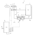
- FIG. 1 is an explanatory view conceptually showing the configuration of a fuel cell system according to an embodiment of the present invention.
- FIG. 2 is an explanatory view showing a specific configuration of the above fuel cell system.
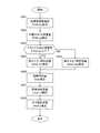
- FIG. 3 is a flow chart showing the flow of start control of the fuel cell system.
- FIG. 4 is a flowchart showing the flow of processing in the power generation heating mode.
- FIG. 5 is an explanatory view showing the relationship between the current and voltage of the fuel cell stack according to the temperature.
- FIG. 6 is an explanatory view showing the relationship between the current and the calorific value of the fuel cell stack.
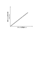
- FIG. 7 is an explanatory view showing the relationship between the temperature of the fuel cell stack and the target power generation amount.
- FIG. 1 is an explanatory view conceptually showing the configuration of a fuel cell system according to an embodiment of the present invention.
- FIG. 2 is an explanatory view showing a specific configuration of the above fuel cell system.
- FIG. 3 is a flow chart showing the flow of start control
- FIG. 8 is an explanatory view showing the relationship between the main fuel flow rate and the sub fuel flow rate at the time of system stop and at the time of power generation.
- FIG. 9 is an explanatory view showing the relationship between the amount of power generation of the fuel cell stack and the main fuel flow rate.
- FIG. 10 is an operation explanatory view (PRD1) of start control.
- FIG. 11 is an operation explanatory view (PRD4) of start control.
- FIG. 12 is an operation explanatory diagram of control at normal time after activation.
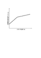
- Figure 13 is a time chart showing changes of the combustor temperature T cmb, stack temperature T stk and fuel flow m Fuel (main fuel flow rate m Fuel_m, sub fuel flow m fuel_s) in the startup control.
- FIG. 14 is a flowchart showing a flow of start control of a fuel cell system according to another embodiment of the present invention.
- FIG. 15 is an explanatory view showing the relationship between the temperature of the fuel cell stack and the target combustor temperature
- FIG. 1 conceptually shows the configuration of a fuel cell system S according to an embodiment of the present invention.
- a fuel cell system (hereinafter referred to as “fuel cell system” and may be simply referred to as “system”) S according to the present embodiment includes a fuel cell stack 1, a fuel processing unit 2, an oxidant gas heating unit 3, A combustor 4 and a control unit 5 are provided.
- a fuel cell stack (hereinafter sometimes simply referred to as "stack") 1 is configured by stacking a plurality of fuel cells or fuel cell unit cells, and each fuel cell serving as a power source is, for example, a solid oxide type It is a fuel cell (SOFC).
- Fuel cell stack 1 includes, in an anode system, an anode gas passage 11 for supplying a fuel gas to the anode electrode of the fuel cell, and an anode off gas passage 11 exh for flowing an anode off gas after a power generation reaction discharged from the anode electrode.
- a cathode gas passage 12 for supplying an oxidant gas to the cathode electrode of the fuel cell in the cathode system, and a cathode off gas after power generation reaction discharged from the cathode electrode in the cathode system.
- a cathode off gas passage 12 exh (not shown) for flowing the
- the fuel processing unit 2 is for processing a raw fuel which is a primary fuel to generate a fuel gas used for a power generation reaction in a fuel cell.
- the fuel processor 2 is interposed in the anode gas passage 11, and receives the supply of raw fuel (arrow A1).
- the oxidant gas heating unit 3 is for heating the oxidant gas.
- the oxidant gas heating unit 3 is interposed in the cathode gas passage 12 and receives the supply of oxidant gas (arrow B).
- the oxidant gas is, for example, air, and oxygen used for a power generation reaction can be supplied to the cathode electrode by supplying air in the atmosphere to the cathode electrode of the fuel cell.
- Suction of oxidant gas or air from the atmosphere to the cathode gas passage 12 is carried out, for example, by an air suction means 6 such as an air compressor or blower installed near the open end of the cathode gas passage 12.
- reaction involved in power generation at the anode and cathode of the solid oxide fuel cell can be represented by the following equation.
- the combustor 4 burns the raw fuel of the fuel cell to generate combustion gas.
- the combustor 4 receives the supply of the raw fuel (arrow A2) and receives the supply of the raw fuel oxidant (arrow C).
- the amount of heat generated by the combustion is supplied to the fuel processing unit 2 and the oxidant gas heating unit 3 and used to heat the raw fuel and the oxidant gas.
- FIG. 1 shows the transfer of heat from the combustor 4 to the fuel processor 2 and the oxidant gas heater 3 by thick dotted lines.
- the fuel cell stack 1 itself is not targeted for direct heating by the combustion gas, but the invention is not limited to this, and combustion may be performed by putting the combustor 4 and the fuel cell stack 1 in a common heat insulating case. It is also possible to configure so that the heat quantity of the gas is directly transmitted to the fuel cell stack 1.
- the control unit 5 controls the supply of the raw fuel to the fuel processing unit 2 and the combustor 4 and can be configured to include an electronic control unit.
- the control unit 5 is configured to supply the raw fuel to the controller 4 configured as an electronic control unit, the main fuel supply unit 52 for supplying the raw fuel to the fuel processing unit 2, and the combustor 4.
- the sub-fuel supply unit 53 of The fuel supply units 52 and 53 may both be injectors, and in the present embodiment, the main fuel supply unit 52 includes a first fuel injector, and the sub fuel supply unit 53 includes a second fuel injector.
- the first fuel injector 52 and the second fuel injector 53 operate in response to a command signal from the controller 51, and can continuously or intermittently supply the raw fuel to the fuel processor 2 and the combustor 4.
- the controller 51 determines whether or not the fuel cell stack 1 or the fuel cell is in a state capable of generating power. This determination can be performed based on, for example, the temperature of the fuel cell stack 1.
- the controller 51 supplies raw fuel to the fuel processing unit 2 through the first fuel injector 52 and supplies raw fuel to the combustor 4 through the second fuel injector 53 when the fuel cell stack 1 is in a state capable of generating power. Do. That is, when the temperature of the fuel cell stack 1 rises after the start of the start, and power generation becomes possible, the fuel cell stack 1 starts power generation, and both the fuel processing unit 2 and the combustor 4 Supply. As a result, the fuel cell stack 1 is heated by the amount of heat generated by power generation, and the combustion gas generated by the combustor 4 can also be used as a heat source to promote the warm-up of the fuel cell stack 1.
- the control unit 5 configures a “supply control unit” and a “power generation control unit” according to the present embodiment.
- FIG. 2 shows a specific configuration of the fuel cell system S.
- the fuel cell system S includes a solid oxide fuel cell (SOFC) as a power source, and includes a fuel tank 7 that can be mounted on a vehicle.
- the raw fuel which is the primary fuel is a mixture of oxygenated fuel (for example, ethanol) and water, and is stored in the fuel tank 7.
- the fuel tank 7 and the fuel cell stack 1 are connected via the anode gas passage 11, and the evaporator 21, the fuel heat exchanger 22, and the reformer are connected to the anode gas passage 11 sequentially from the upstream side with respect to the flow direction. 23 are interspersed.
- a branch fuel passage 11sub branches from the anode gas passage 11 on the upstream side of the evaporator 21, and the branch fuel passage 11sub is connected to the combustor 41.
- a first fuel injector 52 is interposed in the anode gas passage 11 between the branch point of the branch fuel passage 11sub and the evaporator 21, and a second fuel injector 53 is interposed in the branch fuel passage 11sub.
- the evaporator 21 receives a supply of an aqueous ethanol solution, which is a raw fuel, from the fuel tank 7 and heats it to evaporate both ethanol and water to produce ethanol gas and water vapor.
- an aqueous ethanol solution which is a raw fuel
- the fuel heat exchanger 22 receives the amount of heat of the combustion gas from the combustor 41 and heats the ethanol gas and the steam.
- the reformer 23 incorporates a reforming catalyst and generates hydrogen by steam reforming from ethanol in a gaseous state.
- Steam reforming can be represented by the following equation. Steam reforming is an endothermic reaction, and it is necessary to supply heat from the outside at the time of reforming.
- the remaining fuel in the anode off gas is burned by the combustor 41 also during reforming, and the heat quantity of the combustion gas is supplied to the reformer 23.
- the fuel gas of the fuel cell is a mixed gas of hydrogen and carbon dioxide generated by reforming ethanol.
- the oxidant gas heating unit 3 includes an air heat exchanger 31 and heats the oxidant gas flowing through the cathode gas passage 12 by heat exchange with the combustion gas supplied from the combustor 41 through the combustion gas passage 42.
- an air compressor 61 is installed near the open end of the cathode gas passage 12, and air in the atmosphere as the oxidant gas is drawn into the cathode gas passage 12 through the air compressor 61.
- the drawn air is heated from normal temperature (for example, 25 ° C.) when passing through the air heat exchanger 31, and is supplied to the fuel cell stack 1.
- the combustor 41 incorporates a combustion catalyst, receives supply of an aqueous ethanol solution which is a raw fuel through the branched fuel passage 11sub, and generates combustion gas by catalytic combustion of ethanol.
- the combustor 41 and the evaporator 21 are connected via the combustion gas passage 42, while the fuel heat exchanger 22 and the reformer 23 are housed in the heat insulating case shared with the combustor 41 (2
- the quantity of heat of the combustion gas is transmitted to the fuel heat exchanger 22 and the reformer 23 inside the common case L, which is indicated by the dotted line L).
- the combustor 41 is connected to both the anode off gas passage 11 exh and the cathode off gas passage 12 exh extending from the fuel cell stack 1, and when the fuel cell system S starts up, the combustor 41 is connected via the cathode off gas passage 12 exh It is possible to supply an oxidant gas to C.41. Furthermore, when reforming the raw fuel, the anode off gas and the cathode off gas are supplied to the combustor 41, and the remaining fuel (ethanol) in the anode off gas is reacted with the oxygen remaining in the cathode off gas over the catalyst. It is possible to heat the evaporator 21, the fuel heat exchanger 22 and the reformer 23.
- the power generated by the fuel cell stack 1 can be used to charge a battery or drive an external device such as an electric motor or a motor generator.
- the fuel cell system S can be applied to a drive system for a vehicle, and the battery generated by the rated operation of the fuel cell stack 1 is charged to the battery, and the battery is powered according to the target driving force of the vehicle. Supply to the motor generator for traveling.
- the controller 51 controls the operation of the first fuel injector 52, the second fuel injector 53, the air compressor 61, and various devices or components required to operate the fuel cell system S.
- the controller 51 is configured as an electronic control unit including a microcomputer including a central processing circuit, various storage devices such as a ROM and a RAM, an input / output interface and the like.
- the controller 51 sets the supply flow rate (hereinafter referred to as “normal supply flow rate”) of the raw fuel required for the rated operation of the fuel cell stack 1 during normal operation (hereinafter simply referred to as “normal time”).
- the raw fuel of the supply flow rate is supplied to the fuel cell stack 1 through the first fuel injector 52.
- the normal operation refers to the operation after the fuel cell stack 1 is completely warmed up
- the rated operation of the fuel cell stack 1 refers to the operation at the maximum power generation output of the fuel cell stack 1.
- the controller 51 detects the generation request of the start of the fuel cell system S based on the signal from the start switch 106, the controller 51 executes start control for warming up the fuel cell stack 1.
- the warm-up of the fuel cell stack 1 refers to raising the temperature of the fuel cell stack 1 that was at a low temperature (for example, normal temperature) while the fuel cell stack 1 is stopped to its operating temperature.
- the operating temperature of the solid oxide fuel cell is about 800 to 1000.degree.
- the controller 51 detects the oxidant gas temperature T cth A signal from the oxidant gas temperature sensor 103, a signal from the reformer temperature sensor 104 that detects the reformer temperature T ref , a signal from the combustor temperature sensor 105 that detects the combustor temperature T cmb, and the like are input.
- the stack temperature T stk is an index indicating the temperature of the fuel cell stack 1 or the fuel cell, and in the present embodiment, the stack temperature sensor 101 is installed near the cathode off gas outlet of the fuel cell stack 1 and detected by the stack temperature sensor 101 Let the stack temperature T stk be the stack temperature.
- the air flow rate m air is the flow rate of the oxidant gas supplied to the fuel cell stack 1.
- an air flow sensor 102 is installed between the cathode gas passage 12, specifically, the air compressor 61 and the air heat exchanger 31, and the air flow m air is detected by the flow detected by the air flow sensor 102. I assume.
- the oxidant gas temperature T cth is adopted as a temperature having a correlation with the inlet temperature of the fuel cell stack 1, and in the present embodiment, the oxidant gas temperature sensor 103 is installed near the oxidant gas inlet of the fuel cell stack 1. The temperature detected by the oxidant gas temperature sensor 103 is taken as the oxidant gas temperature T cth .
- the reformer temperature T ref is an index indicating the temperature of the catalyst provided in the reformer 23.
- the reformer temperature sensor 104 is installed in the anode gas passage 11 on the downstream side of the reformer 23.
- the temperature detected by the reformer temperature sensor 104 in other words, the temperature of the fuel gas generated by the reforming, is taken as the reformer temperature T ref .
- the combustor temperature T cmb is the temperature of the combustion gas generated by the combustor 4, and in the present embodiment, the combustor temperature sensor 105 is installed in the combustion gas passage 42 between the combustor 41 and the air heat exchanger 31. The temperature detected by the combustor temperature sensor 105 is set as the combustor temperature T cmb .
- FIG. 3 is a flowchart showing a flow of start control of the fuel cell system S according to the present embodiment.
- the controller 51 is programmed to execute start control of the fuel cell system S according to the flowchart shown in FIG. 3 when the start request signal is input from the start switch 106 based on the operation of the start switch 106 by the driver.
- the controller 51 starts the start control in response to the input of the start request signal, and ends the determination that the fuel cell stack 1 or the fuel cell has been warmed up.
- the air compressor 61 is operated.
- air in the atmosphere is drawn into the cathode gas passage 12 and supplied to the cathode of the fuel cell stack 1 via the air heat exchanger 31.
- the stack temperature T stk reads the air flow rate m air and the oxidizing gas temperature T cth.
- S103 it is determined whether the fuel cell stack 1 is in a state capable of generating power. Specifically, after the start control is started, it is determined whether the stack temperature Tstk rises and the power generation lower limit temperature of the fuel cell stack 1 (hereinafter referred to as "power generation start temperature") T1 is reached. If the stack temperature Tstk has reached the power generation start temperature T1, the process proceeds to S104, and if not, the process proceeds to S105.
- the power generation start temperature T1 is 500 ° C., for example.
- the power generation heating mode is selected and executed as the operation mode at the time of warm-up.
- the power generation heating mode is an operation mode that mainly uses the amount of heat generated by the power generation of the fuel cell stack 1.
- the controller 51 controls the power conversion device 201 (FIG. 1) interposed between the fuel cell stack 1 and the battery or accessory to execute the output from the fuel cell stack 1.
- an air compressor 61 can be illustrated as an auxiliary machine.
- the combustion heating mode is selected and executed as the operation mode at the time of warm-up.
- the combustion heating mode is an operation mode that mainly uses the amount of heat generated by the combustion in the combustor 41.
- S106 it is determined whether the fuel cell stack 1 has been warmed up. Specifically, it is determined whether or not has reached a predetermined temperature T wup for stack temperature T stk to determine the completion of warming up. If stack temperature T stk has reached the predetermined temperature T wup, as warming up the fuel cell stack 1 has been completed, and terminates the start control, it shifts to the normal control when. Under normal conditions, the fuel cell stack 1 is operated at the rated output. If the temperature has not reached the predetermined temperature T wup , the process returns to S102, and the air compressor 61 is continued to operate, while the processes of S102 to S105 are repeated.
- FIG. 4 is a flowchart showing the flow of processing in the power generation heating mode (S104 in FIG. 3).
- a target temperature (hereinafter referred to as "target combustor temperature”) T cmb_trg of the combustor 41 is calculated.
- the target combustor temperature T cmb_trg is a target temperature of the combustion gas generated by the combustor 41, and is calculated based on the stack temperature T stk .
- the stack temperature which is the temperature near the cathode off gas outlet of the fuel cell stack 1, Calculated by adding the temperature difference ⁇ T stk_set and ⁇ T ahx_set to T stk .
- the temperature difference ⁇ T stk_set is a set value of the temperature difference between the oxidant gas inlet of the fuel cell stack 1 and the cathode off gas outlet (hereinafter referred to as “stack inlet / outlet temperature difference”)
- the temperature difference ⁇ T ahx_set is a set value of the temperature difference between the combustion gas inlet of the air heat exchanger 31 and the oxidant gas outlet.
- the temperature difference ⁇ T stk_set is a temperature difference (eg, 300 ° C.) which is acceptable from the viewpoint of the heat load on the fuel cell
- the temperature difference ⁇ T ahx_set is given by the air heat exchanger 31 at the rated operation of the fuel cell stack 1. It is a temperature difference (for example, 150 ° C.).
- T cmb_trg T stk + ⁇ T stk_set + ⁇ T ahx_set (3)
- a target power generation amount (hereinafter referred to as "target stack power generation amount") Pstk_trg of the fuel cell stack 1 is calculated.
- the target stack power generation amount Pstk_trg is set to the maximum power generation amount that can be output by the fuel cell stack 1 according to the temperature thereof, and the calculation thereof is performed, for example, by searching from table data of the tendency shown in FIG.
- Target stack power generation amount P Stk_trg is set to a greater value as when the stack temperature T stk high.
- FIG. 5 shows the current-voltage characteristics of the fuel cell stack 1.
- the characteristic at low temperature is indicated by a thin solid line L1
- the characteristic at high temperature or in a normal state is indicated by a thick solid line Lh.
- the fuel cell stack 1 recovers its characteristics as the temperature rises, and the current I stk at the lower limit voltage Vmin at which power can be generated also increases.
- FIG. 6 shows the relationship between the current I stk of the fuel cell stack 1 and the calorific value H stk .
- the stack heat generation amount H stk tends to increase as the current I stk increases, in other words, as the voltage V stk decreases. Therefore, the stack heat generation amount Hstk is maximized when the fuel cell stack 1 is caused to generate power at the lower limit voltage Vmin. From the trends shown in FIGS. 5 and 6, it is possible to obtain the relationship shown in FIG.
- the stack inlet / outlet temperature difference ⁇ T stk is equal to or less than a predetermined value ⁇ T1.
- the process proceeds to S204, and when the temperature difference ⁇ T stk exceeds the predetermined value ⁇ T1, the process proceeds to S205.
- the predetermined value ⁇ T1 is, for example, an allowable upper limit value ⁇ T stk_set (for example, 300 ° C.) of the temperature difference.
- the flow rate (hereinafter referred to as "main fuel flow rate”) m fuel_m of the raw fuel supplied through the first fuel injector 52 is set to the minimum main fuel flow rate m fuel_min .
- Minimum main fuel flow rate m Fuel_min compared decrease a supply flow rate of the raw fuel, as a possible lower limit suppress degradation caused in the fuel cell stack 1 can be set in advance by adaptation through experiment or the like.
- fuel starvation deterioration of the electrode due to a shortage of fuel gas
- the raw fuel supplied to the fuel processing unit 2 accounts for the flow rate of the raw fuel (hereinafter referred to as “total raw fuel flow rate”) m fuel_ttl supplied to the entire system at warm-up.
- the ratio is the smallest, in other words, the ratio of the raw fuel supplied to the combustor 41 is the largest.
- the relationship between the main fuel flow rate m Fuel_m and sub fuel flow m Fuel_s shows for each of when the system is stopped (the power before starting) and power generation.
- the minimum main fuel flow rate m Fuel_min is set to a constant value.
- the amount of heat recovered by the anode gas flowing through the fuel processing unit 2 (hereinafter referred to as “the amount of exhaust heat recovery”) Q rec of the heat amount of the fuel gas is calculated.
- Heat recovery amount Q rec is generally because they have a tendency to increase with increasing main fuel flow rate m Fuel_m, can be calculated as a function of the main fuel flow rate m fuel_m. Not limited to this, the exhaust heat recovery amount Q rec may be set as a constant value.
- the total raw fuel / fuel flow rate m fuel — ttl is calculated.
- the calculation of the raw fuel total flow rate m fuel — ttl is according to the following equation.
- the following equation basically indicates that the heat balance in the whole system is balanced, with the amount of heat introduced by the supply of the raw fuel through the first and second fuel injectors 52, 53 as an input.
- m fuel_ttl A / B (4.1)
- A m air x ⁇ h air (T cmb )-h air (T stk ) ⁇ + m h2 c x ⁇ h h2 (T stk )-h h2 o (T stk ) ⁇ -Q rec ...
- m fuel_ttl Raw fuel total flow rate (molar ratio converted value)
- m air Molar flow of air
- m h 2 c Hydrogen consumption by power generation
- Q rec Exhaust heat recovery amount of anode gas
- T stk Exit temperature of fuel cell stack
- T cmb Temperature of combustion gas
- T fuel Temperature of raw fuel h air (T): Enthalpy h c2h5ohl (T) in air: Enthalpy h h2ol (T) in ethanol (liquid): Enthalpy h co2 (T) in water (liquid): Enthalpy h carbon dioxide (T): Water (gas) enthalpy h o2 of) (T): enthalpy above equation oxygen (4.2) is the mass transfer content inside the fuel cell stack 1 (specifically, oxygen transfer partial 2m H2C ⁇ between the electrodes due to power generation Considering h o2 (T stk )), it can be expressed
- A m air ⁇ ⁇ h air (T cmb) -h air (T stk) ⁇ - 2m h2c ⁇ h o2 (T stk) + ⁇ 2m h2c ⁇ h o2 (T stk) -Q rec -Q stk ⁇ -P ... (4.2a)
- Q stk variation in calorific value of anode gas inside fuel cell stack 1
- P amount of power generation
- Q stk exemplify heat reception of anode gas by power generation of fuel cell stack 1 and heat absorption by internal reforming Can.
- the following relationship may be taken into consideration when calculating the raw fuel total flow rate m fuel — ttl .
- the following equation shows that the heat balance of the anode gas is balanced between the input and output of the fuel cell stack 1.
- the following equation shows the variation of heat of the anode gas in the fuel cell stack 1, the right side third and fourth terms of the equation (4.2a) ( ⁇ 2m h2c ⁇ h o2 (T stk) -Q rec It is possible to approximate -Q stk ⁇ -P).
- C D (5.1)
- C m fuel_m ⁇ ⁇ (1/5 ) ⁇ h c2h5ohl (T fuel) + (4/5) ⁇ h h2ol (T fuel) ⁇ + ⁇ 2m h2c ⁇ h o2 (T stk) -Q rec -Q stk ⁇ -P ...
- the controller 51 sets a command signal corresponding to the main fuel flow rate m Fuel_m and sub fuel flow m Fuel_s, the first fuel injector 52, and outputs to the drive circuit of the second fuel injectors 53.
- the controller 51, the first fuel injector 52, and the second fuel injector 53 constitute a "supply control unit", and the controller 51 constitutes a "power generation control unit”.
- the function of the “power generation control unit” is embodied as the process (control of the power conversion device) of S104 of the flowchart shown in FIG. 3, and the whole of S102 to 104 of the flowchart shown in FIG.
- the function of the "supply control unit” is embodied.
- the function of "warm-up target flow rate setting unit” is embodied as the process of S102 of the flowchart shown in FIG. 3 and S201 to S207 of the flowchart shown in FIG.
- the function of the "gas temperature setting unit” is embodied, and the function of the "fuel cell temperature detection unit” is embodied as the process of S102 shown in FIG. Furthermore, the execution time of the process shown in S204 of the flowchart shown in FIG. 4 corresponds to the "second supply mode", and the execution time of the process shown in S205 corresponds to the "first supply mode”.
- FIG. 10 shows the operation at startup (before the start of power generation by the fuel cell stack 1)
- FIG. 11 shows the operation after the start of power generation at startup
- FIG. 12 shows the operation at normal times after startup. There is.
- the passage through which the gas actually flows is shown by a thick solid line
- the passage through which the flow of the gas is stopped is shown by a thin dotted line.
- FIG. 13 shows the operation of the fuel cell system S at start-up (PRD1 to PRD4) in a time chart.
- the upper part of the figure shows changes in the combustor temperature T cmb , the reformer temperature T ref and the stack temperature T stk
- the lower part of the same figure shows the change of the fuel flow rate m fuel respectively.
- the lower time chart indicated by the solid line of the main fuel flow rate m Fuel_m it shows by dashed lines the sub fuel flow m fuel_s.
- a period PRD1 indicates a period in which the reformer 23 is not in a reformable state
- periods PRD2 to PRD4 indicate a period in which the reformer 23 is in a reformable state.
- Periods PRD1 to PRD3 indicate periods in which the fuel cell stack 1 can not generate power
- period PRD4 indicates a period in which the fuel cell stack 1 can generate power.
- the temperature of the combustor 41 (combustor temperature T cmb ) is limited to the combustor upper limit temperature T cmb_max or less throughout the startup control.
- the limitation of the combustor temperature T cmb is, for example, by limiting the target combustor temperature T cmb_trg set by the process of S201 shown in FIG. 4 to the combustor upper limit temperature T cmb_max or less.
- the upper limit temperature at which the deterioration of the catalyst (for example, the oxidation catalyst) provided in the combustor 41 can be suppressed can be exemplified as the combustor upper limit temperature T cmb_max .
- the air taken in the cathode gas passage 12 by the air compressor 61 is heated by the air heat exchanger 31 by heat exchange with the combustion gas, and the air after heating is supplied to the fuel cell stack 1 to make the fuel cell stack 1 Heat up.
- warm-up of the fuel cell stack 1 proceeds, and the stack temperature Tstk rises (FIG. 13).
- the cathode off gas (oxidant gas) discharged from the fuel cell stack 1 is led to the combustor 41 via the cathode off gas passage 12exh, and the remaining oxygen in the cathode off gas is used as an oxidant for the raw fuel.
- the reformer temperature T ref is further increased, the raw fuel total flow rate m Fuel_ttl is below the rated flow m fuel_rtd (time t2), the supply of the raw fuel through the second fuel injector 53 is stopped, the raw fuel Total The raw fuel with the flow rate m fuel — ttl is supplied to the reformer 23 through the first fuel injector 52 (FIG. 13, period PRD3).
- the fuel cell stack 1 is caused to generate power, and raw fuel is generated through both the first and second fuel injectors 52 and 53. Supply. Specifically, the switch circuit (not shown) of the junction box provided between fuel cell stack 1 and power converter 201 (FIG. 2) is closed to start output from fuel cell stack 1.
- the raw fuel of the flow (minimum main fuel flow m fuel_min or maximum main fuel flow m fuel_max ) according to the stack inlet / outlet temperature difference ⁇ T stk is supplied through the first fuel injector 52 while the shortage with respect to the total raw fuel flow m fuel_ttl A minute amount of raw fuel is supplied through the second fuel injector 53.
- the combustion gas generated by the combustor 41 is controlled to the target temperature while promoting the warm-up by actively utilizing the self-heating by the power generation of the fuel cell stack 1, and it is necessary for the reforming. It is possible to heat up the fuel cell stack 1 by heating the fuel cell stack 1 together with the heat of the combustion gas.
- the main fuel flow rate m Fuel_m is increased with increasing stack temperature T stk, elevated is restricted more than the rated flow rate m fuel_rtd (time t4). That is, at the time of warm-up, although the increase of the raw fuel total flow m fuel_ttl exceeding the rated flow m fuel_rtd is permitted, the main fuel flow m fuel_m is limited to the rated flow m fuel_rtd or less.
- the fuel cell system S according to the present embodiment is configured as described above, and the operation and effects obtained by the present embodiment will be described below.
- the fuel cell stack 1 when starting up the fuel cell system S, it is determined whether the fuel cell stack 1 is in a state capable of generating power, specifically, whether the stack temperature T stk has reached the power generation start temperature T1.
- the stack temperature Tstk reaches the power generation start temperature T1
- the fuel cell stack 1 is caused to generate power, and the raw fuel is supplied through both the first and second fuel injectors 52, 53.
- the fuel flow rate (the total raw fuel flow m fuel_ttl ) increases with the progress of warm-up. It is possible to heat the fuel cell stack 1 with a large amount of heat and realize rapid warm-up, while suppressing the enlargement of the processing unit (for example, the reformer 23) and the combustor 41.
- the exhaust heat recovery amount Q rec of the anode gas and the power generation amount P stk of the fuel cell stack 1 are taken into account. allowing proper setting of the feed rate of the raw fuel (sub fuel flow rate m fuel_s) and then, the temperature of the combustion gas can be prevented from rising excessively. Thus, the deterioration of the combustor 41 can be suppressed, and the fuel cell stack 1 can be prevented from being subjected to an excessive heat load due to the expansion of the stack inlet / outlet temperature difference ⁇ Tstk .
- the target combustor temperature T cmb_trg based on the stack temperature T stk , it becomes possible to set the target combustor temperature T cmb_trg appropriately in accordance with the progress of the warm-up. Furthermore, the calculation load of the controller 51 at the setting of the target combustor temperature T cmb_trg can be reduced.
- the ratio of the main fuel flow rate m fuel _m to the total raw fuel flow rate m fuel _ttl is switched according to the stack inlet / outlet temperature difference ⁇ T stk .
- the stack inlet / outlet temperature difference ⁇ T stk is relative If the difference is smaller, the minimum main fuel flow rate m fuel_min that reduces the ratio is set (S 204), while if the stack inlet / outlet temperature difference .DELTA.T stk is relatively large, the maximum main fuel flow rate m fuel_max increases the ratio.
- S205 exhaust heat recovery by the anode gas can be promoted and warm-up can be promoted while suppressing the expansion of the stack inlet / outlet temperature difference ⁇ T stk .
- the heat generation amount H stk by the power generation of the fuel cell stack 1 is maximized to promote warm-up. It is possible to reduce the time required for activation.
- FIG. 14 shows a flow of start control (power generation heating mode) of a fuel cell system according to another embodiment of the present invention.
- the configuration of the entire system may be the same as in the previous embodiment shown in FIG. 2, and the controller 51 starts the start control when the start request signal is input from the start switch 106. According to the same flow as shown in, the generation heating mode or the combustion heating mode is selected.
- the S301 When the power heating mode is selected, the S301, and calculates the target stack power generation amount P Stk_trg based on stack temperature T stk. Specifically, the same processing as that of S202 in the flowchart shown in FIG. 4 is performed.
- a target combustor temperature T cmb_trg is calculated.
- the temperature is calculated based on the outlet temperature of the fuel cell stack 1 (for example, the stack temperature T stk ) as a temperature for suppressing excessive temperature rise of the combustor 41.
- the stack inlet / outlet temperature The temperature can be calculated based on the inlet temperature of the fuel cell stack 1 (for example, the oxidant gas temperature T cth ) as the temperature for suppressing the expansion of the difference ⁇ T stk .
- the target combustor temperature T cmb_trg is calculated as a temperature according to the stack temperature T stk by searching from table data of the tendency shown in FIG.
- the target combustor temperature T cmb_trg is set to a larger value as the stack temperature T stk is higher.
- a target combustor temperature T cmb_trg preset as a temperature giving the oxidant gas temperature Tcth is calculated.
- the calculation time can be shortened by searching the table data as in S303.
- the raw fuel total flow rate m fuel — ttl is calculated.
- the difference between the target combustor temperature T cmb_trg and the combustor temperature T cmb (the temperature detected by the combustor temperature sensor 105) is input to a feedback controller such as a PI controller (not shown), and the difference is 0
- the correction amount to be close to is added to the raw fuel total flow rate m fuel — ttl .
- the fuel flow rate m Fuel_m while simplifying the calculation of m Fuel_s, it is possible to contribute to the realization of the rapid warm-up.
Landscapes
- Engineering & Computer Science (AREA)
- Chemical & Material Sciences (AREA)
- Life Sciences & Earth Sciences (AREA)
- Manufacturing & Machinery (AREA)
- Sustainable Development (AREA)
- Sustainable Energy (AREA)
- Chemical Kinetics & Catalysis (AREA)
- Electrochemistry (AREA)
- General Chemical & Material Sciences (AREA)
- Combustion & Propulsion (AREA)
- Fuel Cell (AREA)
Abstract
Provided is a fuel cell system provided with: a fuel cell; a fuel processing unit which processes a raw fuel and generates a fuel gas for the fuel cell; an oxidant gas heating unit which heats an oxidant gas for the fuel cell; a combustor which causes the raw fuel to combust and generates a combustion gas for heating the fuel processing unit and the oxidant gas heating unit; a supply control unit which, at the time of warming-up of the fuel cell, controls the supply of the raw fuel to the fuel processing unit and the combustor; and a power generation control unit which controls a power generation state during warming-up of the fuel cell. When the fuel cell has reached a power generation-enabling temperature, the power generation control unit causes the fuel cell to generate power, and the supply control unit supplies the raw fuel to both the fuel processing unit and the combustor.
Description
本発明は、燃料電池の暖機用に燃焼器を備える燃料電池システムおよびその制御方法に関する。
The present invention relates to a fuel cell system including a combustor for warming up a fuel cell and a control method thereof.
JP2016-154067には、燃料電池システムの起動に際し、起動用燃焼器と改質器との間で原燃料の供給先を切り換えることが開示されている(段落0032、0033)。具体的には、起動用燃焼器に改質前の燃料である原燃料を供給する第1燃料供給流路と、改質器に原燃料を供給する第2燃料供給流路と、を設け、改質器の温度が改質可能温度に満たないうちは、第1燃料供給流路を通じて起動用燃焼器に原燃料を供給し、燃焼ガスの熱量により燃料電池を加熱する一方、改質器の温度が改質可能温度に達した後は、第2燃料供給流路を通じて改質器に原燃料を供給し、発電で生じた熱量により燃料電池の更なる昇温を図ることとしている。
JP2016-154067 discloses switching the supply destination of the raw fuel between the start-up combustor and the reformer when the fuel cell system is started (paragraphs 0032 and 0033). Specifically, there are provided a first fuel supply flow passage for supplying a raw fuel which is a fuel before reforming to a start-up combustor, and a second fuel supply flow passage for supplying the raw fuel to a reformer. As long as the temperature of the reformer does not reach the reformable temperature, the raw fuel is supplied to the start-up combustor through the first fuel supply passage, and the heat of the combustion gas heats the fuel cell. After the temperature reaches the reformable temperature, the raw fuel is supplied to the reformer through the second fuel supply flow path, and the amount of heat generated by the power generation further raises the temperature of the fuel cell.
固体酸化物型燃料電池等、動作温度が高い燃料電池を備えるシステムでは、起動に際し、燃料電池の暖機のために低温動作型のものと比べてより大きな熱量を生じさせる必要がある。ここで、燃料電池の暖機に要する時間を短縮しようとした場合は、原燃料の供給流量を増大させることが必要となる。これに対し、原燃料の供給先を起動用燃焼器と改質器との間で単に切り換えるだけでは、燃料流量の増大に対応するため、起動用燃焼器ばかりでなく、改質器についても起動時の燃料流量を前提とした設計が必要となり、システム全体の効率を高めるうえで不利となる。
In a system including a fuel cell with a high operating temperature, such as a solid oxide fuel cell, it is necessary to generate a larger amount of heat upon startup in order to warm up the fuel cell as compared to a low temperature operation type. Here, in order to shorten the time required to warm up the fuel cell, it is necessary to increase the supply flow rate of the raw fuel. On the other hand, simply switching the supply destination of the raw fuel between the start-up combustor and the reformer copes with the increase of the fuel flow rate, so that not only the start-up combustor but also the reformer is started up. The design must be based on the fuel flow rate at the time, which is disadvantageous for improving the overall system efficiency.
さらに、JP2016-154067では、燃料電池による発電が可能となった後の制御について、何ら言及されていない。
Furthermore, JP2016-154067 does not mention anything about control after fuel cell power generation has become possible.
本発明は、以上の問題を考慮した燃料電池システムおよび燃料電池システムの制御方法を提供することを目的とする。
An object of the present invention is to provide a fuel cell system and a control method of the fuel cell system in consideration of the above problems.
本発明の一形態では、燃料電池システムが提供される。本形態に係る燃料電池システムは、燃料電池と、原燃料を処理し、燃料電池の燃料ガスを生成する燃料処理部と、燃料電池の酸化剤ガスを加熱する酸化剤ガス加熱部と、原燃料を燃焼させ、燃料処理部および酸化剤ガス加熱部を加熱するための燃焼ガスを生成する燃焼器と、燃料電池の暖機時に、燃料処理部および燃焼器に対する原燃料の供給を制御する供給制御部と、燃料電池の暖機時における発電状態を制御する発電制御部と、を備える。そして、燃料電池がその発電可能温度に達した場合に、発電制御部により、燃料電池に発電を行わせ、供給制御部により、燃料処理部および燃焼器の双方に原燃料を供給する。
In one aspect of the present invention, a fuel cell system is provided. The fuel cell system according to the present embodiment includes a fuel cell, a fuel processing unit that processes a raw fuel and generates fuel gas for the fuel cell, an oxidant gas heating unit that heats an oxidant gas of the fuel cell, and a raw fuel And a burner for generating combustion gas for heating the fuel processing unit and the oxidant gas heating unit, and supply control for controlling the supply of raw fuel to the fuel processing unit and the combustor when the fuel cell is warmed up And a power generation control unit that controls a power generation state at the time of warm-up of the fuel cell. Then, when the fuel cell reaches the power generation possible temperature, the power generation control unit causes the fuel cell to generate power, and the supply control unit supplies the raw fuel to both the fuel processing unit and the combustor.
以下、図面を参照して、本発明の実施形態について説明する。
Hereinafter, embodiments of the present invention will be described with reference to the drawings.
(燃料電池システムの全体構成)
図1は、本発明の一実施形態に係る燃料電池システムSの構成を概念的に示している。 (Overall configuration of fuel cell system)
FIG. 1 conceptually shows the configuration of a fuel cell system S according to an embodiment of the present invention.
図1は、本発明の一実施形態に係る燃料電池システムSの構成を概念的に示している。 (Overall configuration of fuel cell system)
FIG. 1 conceptually shows the configuration of a fuel cell system S according to an embodiment of the present invention.
本実施形態に係る燃料電池システム(以下「燃料電池システム」といい、単に「システム」という場合がある)Sは、燃料電池スタック1と、燃料処理部2と、酸化剤ガス加熱部3と、燃焼器4と、制御部5と、を備える。
A fuel cell system (hereinafter referred to as “fuel cell system” and may be simply referred to as “system”) S according to the present embodiment includes a fuel cell stack 1, a fuel processing unit 2, an oxidant gas heating unit 3, A combustor 4 and a control unit 5 are provided.
燃料電池スタック(以下、単に「スタック」という場合がある)1は、複数の燃料電池または燃料電池単位セルを積層して構成され、発電源である個々の燃料電池は、例えば、固体酸化物型燃料電池(SOFC)である。燃料電池スタック1は、アノード系において、燃料電池のアノード極に燃料ガスを供給するためのアノードガス通路11と、アノード極から排出される発電反応後のアノードオフガスを流すためのアノードオフガス通路11exh(図1において、図示せず)と、を備える一方、カソード系において、燃料電池のカソード極に酸化剤ガスを供給するためのカソードガス通路12と、カソード極から排出される発電反応後のカソードオフガスを流すためのカソードオフガス通路12exh(図示せず)と、を備える。
A fuel cell stack (hereinafter sometimes simply referred to as "stack") 1 is configured by stacking a plurality of fuel cells or fuel cell unit cells, and each fuel cell serving as a power source is, for example, a solid oxide type It is a fuel cell (SOFC). Fuel cell stack 1 includes, in an anode system, an anode gas passage 11 for supplying a fuel gas to the anode electrode of the fuel cell, and an anode off gas passage 11 exh for flowing an anode off gas after a power generation reaction discharged from the anode electrode. In FIG. 1, a cathode gas passage 12 for supplying an oxidant gas to the cathode electrode of the fuel cell in the cathode system, and a cathode off gas after power generation reaction discharged from the cathode electrode in the cathode system. And a cathode off gas passage 12 exh (not shown) for flowing the
燃料処理部2は、一次燃料である原燃料を処理し、燃料電池での発電反応に用いられる燃料ガスを生成するためのものである。燃料処理部2は、アノードガス通路11に介装され、原燃料の供給を受ける(矢印A1)。
The fuel processing unit 2 is for processing a raw fuel which is a primary fuel to generate a fuel gas used for a power generation reaction in a fuel cell. The fuel processor 2 is interposed in the anode gas passage 11, and receives the supply of raw fuel (arrow A1).
酸化剤ガス加熱部3は、酸化剤ガスを加熱するためのものである。酸化剤ガス加熱部3は、カソードガス通路12に介装され、酸化剤ガスの供給を受ける(矢印B)。酸化剤ガスは、例えば、空気であり、大気中の空気を燃料電池のカソード極に供給することにより、発電反応に用いられる酸素をカソード極に供給することが可能である。大気からカソードガス通路12への酸化剤ガスないし空気の吸入は、例えば、カソードガス通路12の開放端付近に設置されるエアコンプレッサまたはブロア等の空気吸入手段6による。
The oxidant gas heating unit 3 is for heating the oxidant gas. The oxidant gas heating unit 3 is interposed in the cathode gas passage 12 and receives the supply of oxidant gas (arrow B). The oxidant gas is, for example, air, and oxygen used for a power generation reaction can be supplied to the cathode electrode by supplying air in the atmosphere to the cathode electrode of the fuel cell. Suction of oxidant gas or air from the atmosphere to the cathode gas passage 12 is carried out, for example, by an air suction means 6 such as an air compressor or blower installed near the open end of the cathode gas passage 12.
ここで、固体酸化物型燃料電池のアノード極およびカソード極での発電に係る反応は、次式により表すことができる。
Here, the reaction involved in power generation at the anode and cathode of the solid oxide fuel cell can be represented by the following equation.
アノード極: 2H2+4O2- → 2H2O+4e- …(1.1)
カソード極: O2+4e- → 2O2- …(1.2)
燃焼器4は、燃料電池の原燃料を燃焼させ、燃焼ガスを生成する。燃焼器4は、原燃料の供給を受けるとともに(矢印A2)、原燃料の酸化剤の供給を受ける(矢印C)。燃焼により生じた熱量は、燃料処理部2および酸化剤ガス加熱部3に供給され、原燃料および酸化剤ガスの加熱に用いられる。図1は、燃焼器4から燃料処理部2および酸化剤ガス加熱部3への熱量の移動を、太い点線により示している。本実施形態では、燃料電池スタック1自体を燃焼ガスによる直接的な加熱の対象としないが、これに限らず、燃焼器4と燃料電池スタック1とを共用の断熱ケースに収めるなどして、燃焼ガスの熱量が燃料電池スタック1に対して直接的に伝わるように構成することも可能である。 Anode: 2H 2 + 4O 2- → 2H 2 O + 4e - ... (1.1)
The cathode: O 2 + 4e - → 2O 2- ... (1.2)
Thecombustor 4 burns the raw fuel of the fuel cell to generate combustion gas. The combustor 4 receives the supply of the raw fuel (arrow A2) and receives the supply of the raw fuel oxidant (arrow C). The amount of heat generated by the combustion is supplied to the fuel processing unit 2 and the oxidant gas heating unit 3 and used to heat the raw fuel and the oxidant gas. FIG. 1 shows the transfer of heat from the combustor 4 to the fuel processor 2 and the oxidant gas heater 3 by thick dotted lines. In the present embodiment, the fuel cell stack 1 itself is not targeted for direct heating by the combustion gas, but the invention is not limited to this, and combustion may be performed by putting the combustor 4 and the fuel cell stack 1 in a common heat insulating case. It is also possible to configure so that the heat quantity of the gas is directly transmitted to the fuel cell stack 1.
カソード極: O2+4e- → 2O2- …(1.2)
燃焼器4は、燃料電池の原燃料を燃焼させ、燃焼ガスを生成する。燃焼器4は、原燃料の供給を受けるとともに(矢印A2)、原燃料の酸化剤の供給を受ける(矢印C)。燃焼により生じた熱量は、燃料処理部2および酸化剤ガス加熱部3に供給され、原燃料および酸化剤ガスの加熱に用いられる。図1は、燃焼器4から燃料処理部2および酸化剤ガス加熱部3への熱量の移動を、太い点線により示している。本実施形態では、燃料電池スタック1自体を燃焼ガスによる直接的な加熱の対象としないが、これに限らず、燃焼器4と燃料電池スタック1とを共用の断熱ケースに収めるなどして、燃焼ガスの熱量が燃料電池スタック1に対して直接的に伝わるように構成することも可能である。 Anode: 2H 2 + 4O 2- → 2H 2 O + 4e - ... (1.1)
The cathode: O 2 + 4e - → 2O 2- ... (1.2)
The
制御部5は、燃料処理部2および燃焼器4に対する原燃料の供給を制御するものであり、電子制御ユニットを含んで構成することが可能である。本実施形態において、制御部5は、電子制御ユニットとして構成されたコントローラ51と、燃料処理部2に原燃料を供給するためのメイン燃料供給ユニット52と、燃焼器4に原燃料を供給するためのサブ燃料供給ユニット53と、を備える。燃料供給ユニット52および53は、いずれもインジェクタであってよく、本実施形態では、メイン燃料供給ユニット52として第1燃料インジェクタを備え、サブ燃料供給ユニット53として第2燃料インジェクタを備える。第1燃料インジェクタ52および第2燃料インジェクタ53は、コントローラ51からの指令信号に応じて作動し、燃料処理部2および燃焼器4に対して原燃料を連続的または間欠的に供給可能である。
The control unit 5 controls the supply of the raw fuel to the fuel processing unit 2 and the combustor 4 and can be configured to include an electronic control unit. In the present embodiment, the control unit 5 is configured to supply the raw fuel to the controller 4 configured as an electronic control unit, the main fuel supply unit 52 for supplying the raw fuel to the fuel processing unit 2, and the combustor 4. And the sub-fuel supply unit 53 of The fuel supply units 52 and 53 may both be injectors, and in the present embodiment, the main fuel supply unit 52 includes a first fuel injector, and the sub fuel supply unit 53 includes a second fuel injector. The first fuel injector 52 and the second fuel injector 53 operate in response to a command signal from the controller 51, and can continuously or intermittently supply the raw fuel to the fuel processor 2 and the combustor 4.
コントローラ51は、燃料電池システムSの起動に際し、燃料電池スタック1ないし燃料電池が発電可能な状態にあるか否かを判定する。この判定は、例えば、燃料電池スタック1の温度をもとに行うことが可能である。コントローラ51は、燃料電池スタック1が発電可能な状態にある場合に、第1燃料インジェクタ52を通じて燃料処理部2に原燃料を供給するとともに、第2燃料インジェクタ53を通じて燃焼器4に原燃料を供給する。つまり、起動開始後、燃料電池スタック1の温度が上昇し、発電可能な状態に至った場合は、燃料電池スタック1による発電を開始し、燃料処理部2および燃焼器4の双方に原燃料を供給するのである。これにより、発電により生じた熱量により燃料電池スタック1を加熱するとともに、燃焼器4により生成された燃焼ガスをも熱源として、燃料電池スタック1の暖機を促すことが可能となる。
When starting the fuel cell system S, the controller 51 determines whether or not the fuel cell stack 1 or the fuel cell is in a state capable of generating power. This determination can be performed based on, for example, the temperature of the fuel cell stack 1. The controller 51 supplies raw fuel to the fuel processing unit 2 through the first fuel injector 52 and supplies raw fuel to the combustor 4 through the second fuel injector 53 when the fuel cell stack 1 is in a state capable of generating power. Do. That is, when the temperature of the fuel cell stack 1 rises after the start of the start, and power generation becomes possible, the fuel cell stack 1 starts power generation, and both the fuel processing unit 2 and the combustor 4 Supply. As a result, the fuel cell stack 1 is heated by the amount of heat generated by power generation, and the combustion gas generated by the combustor 4 can also be used as a heat source to promote the warm-up of the fuel cell stack 1.
制御部5は、本実施形態に係る「供給制御部」および「発電制御部」を構成する。
The control unit 5 configures a “supply control unit” and a “power generation control unit” according to the present embodiment.
図2は、燃料電池システムSの具体的な構成を示している。
FIG. 2 shows a specific configuration of the fuel cell system S.
燃料電池システムSは、発電源として固体酸化物型燃料電池(SOFC)を備え、車上に搭載可能な燃料タンク7を備える。本実施形態において、一次燃料である原燃料は、含酸素燃料(例えば、エタノール)と水との混合物であり、燃料タンク7に貯蔵されている。燃料タンク7と燃料電池スタック1とが、アノードガス通路11を介して接続され、アノードガス通路11には、流れの方向に関して上流側から順に、蒸発器21、燃料熱交換器22および改質器23が介装されている。他方で、蒸発器21の上流側でアノードガス通路11から分岐燃料通路11subが分岐し、分岐燃料通路11subは、燃焼器41に接続されている。分岐燃料通路11subの分岐点と蒸発器21との間のアノードガス通路11に第1燃料インジェクタ52が介装され、分岐燃料通路11subに第2燃料インジェクタ53が介装されている。これにより、アノードガス通路11と分岐燃料通路11subとの間で原燃料の流通を切り換えることが可能であり、他方で、これらの通路11、11subの双方を介して原燃料を流すことも可能である。蒸発器21、燃料熱交換器22および改質器23は、本実施形態に係る「燃料処理部」を構成する。
The fuel cell system S includes a solid oxide fuel cell (SOFC) as a power source, and includes a fuel tank 7 that can be mounted on a vehicle. In the present embodiment, the raw fuel which is the primary fuel is a mixture of oxygenated fuel (for example, ethanol) and water, and is stored in the fuel tank 7. The fuel tank 7 and the fuel cell stack 1 are connected via the anode gas passage 11, and the evaporator 21, the fuel heat exchanger 22, and the reformer are connected to the anode gas passage 11 sequentially from the upstream side with respect to the flow direction. 23 are interspersed. On the other hand, a branch fuel passage 11sub branches from the anode gas passage 11 on the upstream side of the evaporator 21, and the branch fuel passage 11sub is connected to the combustor 41. A first fuel injector 52 is interposed in the anode gas passage 11 between the branch point of the branch fuel passage 11sub and the evaporator 21, and a second fuel injector 53 is interposed in the branch fuel passage 11sub. Thereby, it is possible to switch the flow of the raw fuel between the anode gas passage 11 and the branch fuel passage 11sub, and on the other hand, it is also possible to flow the raw fuel through both of the passages 11 and 11sub. is there. The evaporator 21, the fuel heat exchanger 22, and the reformer 23 constitute a "fuel processing unit" according to the present embodiment.
蒸発器21は、燃料タンク7から原燃料であるエタノール水溶液の供給を受け、これを加熱して、エタノールと水とをいずれも蒸発させ、エタノールガスおよび水蒸気を生成する。
The evaporator 21 receives a supply of an aqueous ethanol solution, which is a raw fuel, from the fuel tank 7 and heats it to evaporate both ethanol and water to produce ethanol gas and water vapor.
燃料熱交換器22は、燃焼器41から燃焼ガスの熱量を受け、エタノールガスおよび水蒸気を加熱する。
The fuel heat exchanger 22 receives the amount of heat of the combustion gas from the combustor 41 and heats the ethanol gas and the steam.
改質器23は、改質用触媒を内蔵し、気体の状態にあるエタノールから、水蒸気改質により水素を生成する。水蒸気改質は、次式により表すことができる。水蒸気改質は、吸熱反応であり、改質に際して外部から熱量を供給する必要がある。本実施形態では、後に述べるように、改質中も燃焼器41でアノードオフガス中の残燃料を燃焼させ、燃焼ガスの熱量を改質器23に供給する。本実施形態において、燃料電池の燃料ガスは、エタノールの改質により生じた水素と二酸化炭素との混合ガスである。
The reformer 23 incorporates a reforming catalyst and generates hydrogen by steam reforming from ethanol in a gaseous state. Steam reforming can be represented by the following equation. Steam reforming is an endothermic reaction, and it is necessary to supply heat from the outside at the time of reforming. In the present embodiment, as described later, the remaining fuel in the anode off gas is burned by the combustor 41 also during reforming, and the heat quantity of the combustion gas is supplied to the reformer 23. In the present embodiment, the fuel gas of the fuel cell is a mixed gas of hydrogen and carbon dioxide generated by reforming ethanol.
C2H5OH+3H2O → 6H2+2CO2 …(2)
酸化剤ガス加熱部3は、空気熱交換器31により構成され、燃焼器41から燃焼ガス通路42を通じて供給される燃焼ガスとの熱交換により、カソードガス通路12を流れる酸化剤ガスを加熱する。本実施形態では、カソードガス通路12の開放端付近にエアコンプレッサ61が設置され、酸化剤ガスとして大気中の空気が、エアコンプレッサ61を通じてカソードガス通路12に吸入される。吸入された空気は、空気熱交換器31を通過する際に常温(例えば、25℃)から昇温され、燃料電池スタック1に供給される。 C 2 H 5 OH + 3H 2 O → 6H 2 + 2CO 2 (2)
The oxidantgas heating unit 3 includes an air heat exchanger 31 and heats the oxidant gas flowing through the cathode gas passage 12 by heat exchange with the combustion gas supplied from the combustor 41 through the combustion gas passage 42. In the present embodiment, an air compressor 61 is installed near the open end of the cathode gas passage 12, and air in the atmosphere as the oxidant gas is drawn into the cathode gas passage 12 through the air compressor 61. The drawn air is heated from normal temperature (for example, 25 ° C.) when passing through the air heat exchanger 31, and is supplied to the fuel cell stack 1.
酸化剤ガス加熱部3は、空気熱交換器31により構成され、燃焼器41から燃焼ガス通路42を通じて供給される燃焼ガスとの熱交換により、カソードガス通路12を流れる酸化剤ガスを加熱する。本実施形態では、カソードガス通路12の開放端付近にエアコンプレッサ61が設置され、酸化剤ガスとして大気中の空気が、エアコンプレッサ61を通じてカソードガス通路12に吸入される。吸入された空気は、空気熱交換器31を通過する際に常温(例えば、25℃)から昇温され、燃料電池スタック1に供給される。 C 2 H 5 OH + 3H 2 O → 6H 2 + 2CO 2 (2)
The oxidant
燃焼器41は、燃焼用触媒を内蔵し、分岐燃料通路11subを通じて原燃料であるエタノール水溶液の供給を受け、エタノールの触媒燃焼により燃焼ガスを生成する。本実施形態では、燃焼器41と蒸発器21とが燃焼ガス通路42を介して接続される一方、燃料熱交換器22および改質器23が燃焼器41と共用の断熱ケースに収容され(二点鎖線Lにより示す)、燃焼ガスの熱量がこの共用のケースLの内部で燃料熱交換器22および改質器23に伝わるように構成されている。
The combustor 41 incorporates a combustion catalyst, receives supply of an aqueous ethanol solution which is a raw fuel through the branched fuel passage 11sub, and generates combustion gas by catalytic combustion of ethanol. In the present embodiment, the combustor 41 and the evaporator 21 are connected via the combustion gas passage 42, while the fuel heat exchanger 22 and the reformer 23 are housed in the heat insulating case shared with the combustor 41 (2 The quantity of heat of the combustion gas is transmitted to the fuel heat exchanger 22 and the reformer 23 inside the common case L, which is indicated by the dotted line L).
本実施形態において、燃焼器41は、燃料電池スタック1から延びるアノードオフガス通路11exhおよびカソードオフガス通路12exhの双方と接続されており、燃料電池システムSの起動に際し、カソードオフガス通路12exhを介して燃焼器41に酸化剤ガスを供給することが可能である。さらに、原燃料の改質に際し、燃焼器41にアノードオフガスおよびカソードオフガスを供給し、アノードオフガス中の残燃料(エタノール)をカソードオフガスに残存する酸素と触媒上で反応させ、生じた熱量により、蒸発器21、燃料熱交換器22および改質器23を加熱することが可能である。
In the present embodiment, the combustor 41 is connected to both the anode off gas passage 11 exh and the cathode off gas passage 12 exh extending from the fuel cell stack 1, and when the fuel cell system S starts up, the combustor 41 is connected via the cathode off gas passage 12 exh It is possible to supply an oxidant gas to C.41. Furthermore, when reforming the raw fuel, the anode off gas and the cathode off gas are supplied to the combustor 41, and the remaining fuel (ethanol) in the anode off gas is reacted with the oxygen remaining in the cathode off gas over the catalyst. It is possible to heat the evaporator 21, the fuel heat exchanger 22 and the reformer 23.
燃料電池スタック1の発電電力は、バッテリを充電したり、電動モータまたはモータジェネレータ等の外部装置を駆動したりするのに用いることが可能である。例えば、燃料電池システムSは、車両用の駆動システムに適用することが可能であり、燃料電池スタック1の定格運転により生じた電力をバッテリに充電し、車両の目標駆動力に応じた電力をバッテリから走行用のモータジェネレータに供給する。
The power generated by the fuel cell stack 1 can be used to charge a battery or drive an external device such as an electric motor or a motor generator. For example, the fuel cell system S can be applied to a drive system for a vehicle, and the battery generated by the rated operation of the fuel cell stack 1 is charged to the battery, and the battery is powered according to the target driving force of the vehicle. Supply to the motor generator for traveling.
(制御システムの構成)
第1燃料インジェクタ52、第2燃料インジェクタ53およびエアコンプレッサ61、その他、燃料電池システムSの運転に要する各種装置ないし部品の動作は、コントローラ51により制御される。本実施形態において、コントローラ51は、中央演算回路、ROMおよびRAM等の各種記憶装置、入出力インターフェース等を備えるマイクロコンピュータからなる電子制御ユニットとして構成される。 (Configuration of control system)
Thecontroller 51 controls the operation of the first fuel injector 52, the second fuel injector 53, the air compressor 61, and various devices or components required to operate the fuel cell system S. In the present embodiment, the controller 51 is configured as an electronic control unit including a microcomputer including a central processing circuit, various storage devices such as a ROM and a RAM, an input / output interface and the like.
第1燃料インジェクタ52、第2燃料インジェクタ53およびエアコンプレッサ61、その他、燃料電池システムSの運転に要する各種装置ないし部品の動作は、コントローラ51により制御される。本実施形態において、コントローラ51は、中央演算回路、ROMおよびRAM等の各種記憶装置、入出力インターフェース等を備えるマイクロコンピュータからなる電子制御ユニットとして構成される。 (Configuration of control system)
The
コントローラ51は、通常の運転時(以下、単に「通常時」という)において、燃料電池スタック1の定格運転に要する原燃料の供給流量(以下「通常時供給流量」という)を設定し、通常時供給流量の原燃料を、第1燃料インジェクタ52を通じて燃料電池スタック1に供給する。ここで、通常時とは、燃料電池スタック1の暖機が完了した後の運転時をいい、燃料電池スタック1の定格運転とは、燃料電池スタック1の最大発電出力での運転をいう。
The controller 51 sets the supply flow rate (hereinafter referred to as “normal supply flow rate”) of the raw fuel required for the rated operation of the fuel cell stack 1 during normal operation (hereinafter simply referred to as “normal time”). The raw fuel of the supply flow rate is supplied to the fuel cell stack 1 through the first fuel injector 52. Here, the normal operation refers to the operation after the fuel cell stack 1 is completely warmed up, and the rated operation of the fuel cell stack 1 refers to the operation at the maximum power generation output of the fuel cell stack 1.
他方で、コントローラ51は、起動スイッチ106からの信号に基づき燃料電池システムSの起動要求の発生を検知すると、燃料電池スタック1の暖機を行う起動制御を実行する。燃料電池スタック1の暖機とは、停止中に低温(例えば、常温)にあった燃料電池スタック1を、その動作温度にまで昇温させることをいう。固体酸化物型燃料電池の動作温度は、800~1000℃程度である。
On the other hand, when the controller 51 detects the generation request of the start of the fuel cell system S based on the signal from the start switch 106, the controller 51 executes start control for warming up the fuel cell stack 1. The warm-up of the fuel cell stack 1 refers to raising the temperature of the fuel cell stack 1 that was at a low temperature (for example, normal temperature) while the fuel cell stack 1 is stopped to its operating temperature. The operating temperature of the solid oxide fuel cell is about 800 to 1000.degree.
コントローラ51は、起動制御に関わる情報として、スタック温度Tstkを検出するスタック温度センサ101からの信号、空気流量mairを検出する空気流量センサ102からの信号、酸化剤ガス温度Tcthを検出する酸化剤ガス温度センサ103からの信号、改質器温度Trefを検出する改質器温度センサ104からの信号、燃焼器温度Tcmbを検出する燃焼器温度センサ105からの信号等を入力する。
The controller 51, as the information relating to the start control signal from the stack temperature sensor 101 for detecting the stack temperature T stk, the signal from the air flow sensor 102 for detecting the air flow rate m air, detects the oxidant gas temperature T cth A signal from the oxidant gas temperature sensor 103, a signal from the reformer temperature sensor 104 that detects the reformer temperature T ref , a signal from the combustor temperature sensor 105 that detects the combustor temperature T cmb, and the like are input.
スタック温度Tstkは、燃料電池スタック1または燃料電池の温度を示す指標であり、本実施形態では、燃料電池スタック1のカソードオフガス出口付近にスタック温度センサ101を設置し、スタック温度センサ101により検出された温度をもってスタック温度Tstkとする。
The stack temperature T stk is an index indicating the temperature of the fuel cell stack 1 or the fuel cell, and in the present embodiment, the stack temperature sensor 101 is installed near the cathode off gas outlet of the fuel cell stack 1 and detected by the stack temperature sensor 101 Let the stack temperature T stk be the stack temperature.
空気流量mairは、燃料電池スタック1に供給される酸化剤ガスの流量である。本実施形態では、カソードガス通路12、具体的には、エアコンプレッサ61と空気熱交換器31との間に空気流量センサ102を設置し、空気流量センサ102により検出された流量をもって空気流量mairとする。
The air flow rate m air is the flow rate of the oxidant gas supplied to the fuel cell stack 1. In the present embodiment, an air flow sensor 102 is installed between the cathode gas passage 12, specifically, the air compressor 61 and the air heat exchanger 31, and the air flow m air is detected by the flow detected by the air flow sensor 102. I assume.
酸化剤ガス温度Tcthは、燃料電池スタック1の入口温度に対する相関性を有する温度として採用され、本実施形態では、燃料電池スタック1の酸化剤ガス入口付近に酸化剤ガス温度センサ103を設置し、酸化剤ガス温度センサ103により検出された温度をもって酸化剤ガス温度Tcthとする。
The oxidant gas temperature T cth is adopted as a temperature having a correlation with the inlet temperature of the fuel cell stack 1, and in the present embodiment, the oxidant gas temperature sensor 103 is installed near the oxidant gas inlet of the fuel cell stack 1. The temperature detected by the oxidant gas temperature sensor 103 is taken as the oxidant gas temperature T cth .
改質器温度Trefは、改質器23に備わる触媒の温度を示す指標であり、本実施形態では、改質器23の下流側のアノードガス通路11に改質器温度センサ104を設置し、改質器温度センサ104により検出された温度、換言すれば、改質により生じた燃料ガスの温度をもって改質器温度Trefとする。
The reformer temperature T ref is an index indicating the temperature of the catalyst provided in the reformer 23. In the present embodiment, the reformer temperature sensor 104 is installed in the anode gas passage 11 on the downstream side of the reformer 23. The temperature detected by the reformer temperature sensor 104, in other words, the temperature of the fuel gas generated by the reforming, is taken as the reformer temperature T ref .
燃焼器温度Tcmbは、燃焼器4により生成される燃焼ガスの温度であり、本実施形態では、燃焼器41と空気熱交換器31との間の燃焼ガス通路42に燃焼器温度センサ105を設置し、燃焼器温度センサ105により検出された温度をもって燃焼器温度Tcmbとする。
The combustor temperature T cmb is the temperature of the combustion gas generated by the combustor 4, and in the present embodiment, the combustor temperature sensor 105 is installed in the combustion gas passage 42 between the combustor 41 and the air heat exchanger 31. The temperature detected by the combustor temperature sensor 105 is set as the combustor temperature T cmb .
燃料電池システムSの起動制御について、以下にフローチャートを参照して具体的に説明する。
The start control of the fuel cell system S will be specifically described below with reference to the flowchart.
(起動制御の説明)
図3は、本実施形態に係る燃料電池システムSの起動制御の流れを示すフローチャートである。 (Description of start control)
FIG. 3 is a flowchart showing a flow of start control of the fuel cell system S according to the present embodiment.
図3は、本実施形態に係る燃料電池システムSの起動制御の流れを示すフローチャートである。 (Description of start control)
FIG. 3 is a flowchart showing a flow of start control of the fuel cell system S according to the present embodiment.
コントローラ51は、運転者による起動スイッチ106の操作に基づき、起動スイッチ106から起動要求信号を入力すると、図3に示すフローチャートに従って燃料電池システムSの起動制御を実行するようにプログラムされている。本実施形態において、コントローラ51は、起動要求信号の入力をもって起動制御を開始し、燃料電池スタック1ないし燃料電池の暖機が完了したとの判定をもってこれを終了する。
The controller 51 is programmed to execute start control of the fuel cell system S according to the flowchart shown in FIG. 3 when the start request signal is input from the start switch 106 based on the operation of the start switch 106 by the driver. In the present embodiment, the controller 51 starts the start control in response to the input of the start request signal, and ends the determination that the fuel cell stack 1 or the fuel cell has been warmed up.
S101では、エアコンプレッサ61を作動させる。これにより、大気中の空気がカソードガス通路12に吸入され、空気熱交換器31を介して燃料電池スタック1のカソード極に供給される。
In S101, the air compressor 61 is operated. Thus, air in the atmosphere is drawn into the cathode gas passage 12 and supplied to the cathode of the fuel cell stack 1 via the air heat exchanger 31.
S102では、起動制御に関わる情報として、スタック温度Tstk、空気流量mairおよび酸化剤ガス温度Tcthを読み込む。
In S102, as the information relating to the start-up control, the stack temperature T stk, reads the air flow rate m air and the oxidizing gas temperature T cth.
S103では、燃料電池スタック1が発電可能な状態にあるか否かを判定する。具体的には、起動制御の開始後、スタック温度Tstkが上昇し、燃料電池スタック1の発電可能な下限温度(以下「発電開始温度」という)T1に達したか否かを判定する。スタック温度Tstkが発電開始温度T1に達した場合は、S104へ進み、達していない場合は、S105へ進む。発電開始温度T1は、例えば、500℃である。
In S103, it is determined whether the fuel cell stack 1 is in a state capable of generating power. Specifically, after the start control is started, it is determined whether the stack temperature Tstk rises and the power generation lower limit temperature of the fuel cell stack 1 (hereinafter referred to as "power generation start temperature") T1 is reached. If the stack temperature Tstk has reached the power generation start temperature T1, the process proceeds to S104, and if not, the process proceeds to S105. The power generation start temperature T1 is 500 ° C., for example.
S104では、暖機時の動作モードとして、発電加熱モードを選択し、実行する。発電加熱モードは、燃料電池スタック1の発電により生じた熱量を主に利用する動作モードである。発電加熱モードにおいて、コントローラ51は、燃料電池スタック1とバッテリまたは補機との間に介装された電力変換装置201(図1)を制御し、燃料電池スタック1からの出力を実行する。ここで、補機として、エアコンプレッサ61を例示することができる。
In S104, the power generation heating mode is selected and executed as the operation mode at the time of warm-up. The power generation heating mode is an operation mode that mainly uses the amount of heat generated by the power generation of the fuel cell stack 1. In the power generation heating mode, the controller 51 controls the power conversion device 201 (FIG. 1) interposed between the fuel cell stack 1 and the battery or accessory to execute the output from the fuel cell stack 1. Here, an air compressor 61 can be illustrated as an auxiliary machine.
S105では、暖機時の動作モードとして、燃焼加熱モードを選択し、実行する。燃焼加熱モードは、燃焼器41での燃焼により生じた熱量を主に利用する動作モードである。
In S105, the combustion heating mode is selected and executed as the operation mode at the time of warm-up. The combustion heating mode is an operation mode that mainly uses the amount of heat generated by the combustion in the combustor 41.
S106では、燃料電池スタック1の暖機が完了したか否かを判定する。具体的には、スタック温度Tstkが暖機完了を判定するための所定温度Twupに達したか否かを判定する。スタック温度Tstkが所定温度Twupに達した場合は、燃料電池スタック1の暖機が完了したとして、起動制御を終了し、通常時の制御に移行する。通常時では、燃料電池スタック1を定格出力で運転する。所定温度Twupに達していない場合は、S102へ戻り、エアコンプレッサ61を引き続き作動させる一方、S102~105の処理を繰り返し実行する。
In S106, it is determined whether the fuel cell stack 1 has been warmed up. Specifically, it is determined whether or not has reached a predetermined temperature T wup for stack temperature T stk to determine the completion of warming up. If stack temperature T stk has reached the predetermined temperature T wup, as warming up the fuel cell stack 1 has been completed, and terminates the start control, it shifts to the normal control when. Under normal conditions, the fuel cell stack 1 is operated at the rated output. If the temperature has not reached the predetermined temperature T wup , the process returns to S102, and the air compressor 61 is continued to operate, while the processes of S102 to S105 are repeated.
図4は、発電加熱モード(図3のS104)における処理の流れを示すフローチャートである。
FIG. 4 is a flowchart showing the flow of processing in the power generation heating mode (S104 in FIG. 3).
S201では、燃焼器41の目標温度(以下「目標燃焼器温度」という)Tcmb_trgを算出する。目標燃焼器温度Tcmb_trgは、燃焼器41により生成される燃焼ガスの目標温度であり、スタック温度Tstkをもとに算出する。具体的には、燃料電池スタック1への流入が許容される酸化剤ガスの最高温度を与える燃焼ガスの目標温度として、次式により、燃料電池スタック1のカソードオフガス出口付近の温度であるスタック温度Tstkに、温度差ΔTstk_setおよびΔTahx_setを加算して算出する。ここで、温度差ΔTstk_setは、燃料電池スタック1の酸化剤ガス入口部とカソードオフガス出口部との間の温度差(以下「スタック入出口温度差」という)の設定値であり、温度差ΔTahx_setは、空気熱交換器31の燃焼ガス入口部と酸化剤ガス出口部との間の温度差の設定値である。温度差ΔTstk_setは、燃料電池に対する熱負荷の観点から許容される温度差(例えば、300℃)であり、温度差ΔTahx_setは、燃料電池スタック1の定格運転時に空気熱交換器31で与えられる温度差(例えば、150℃)である。
In S201, a target temperature (hereinafter referred to as "target combustor temperature") T cmb_trg of the combustor 41 is calculated. The target combustor temperature T cmb_trg is a target temperature of the combustion gas generated by the combustor 41, and is calculated based on the stack temperature T stk . Specifically, as a target temperature of the combustion gas that gives the maximum temperature of the oxidant gas that can flow into the fuel cell stack 1, the stack temperature, which is the temperature near the cathode off gas outlet of the fuel cell stack 1, Calculated by adding the temperature difference ΔT stk_set and ΔT ahx_set to T stk . Here, the temperature difference ΔT stk_set is a set value of the temperature difference between the oxidant gas inlet of the fuel cell stack 1 and the cathode off gas outlet (hereinafter referred to as “stack inlet / outlet temperature difference”), and the temperature difference ΔT ahx_set is a set value of the temperature difference between the combustion gas inlet of the air heat exchanger 31 and the oxidant gas outlet. The temperature difference ΔT stk_set is a temperature difference (eg, 300 ° C.) which is acceptable from the viewpoint of the heat load on the fuel cell, and the temperature difference ΔT ahx_set is given by the air heat exchanger 31 at the rated operation of the fuel cell stack 1. It is a temperature difference (for example, 150 ° C.).
Tcmb_trg=Tstk+ΔTstk_set+ΔTahx_set …(3)
S202では、燃料電池スタック1の目標発電量(以下「目標スタック発電量」という)Pstk_trgを算出する。目標スタック発電量Pstk_trgは、燃料電池スタック1がその温度に応じて出力可能な最大発電量に設定され、その算出は、例えば、図7に示す傾向のテーブルデータからの検索による。目標スタック発電量Pstk_trgは、スタック温度Tstkが高いときほど大きな値に設定される。 T cmb_trg = T stk + ΔT stk_set + ΔT ahx_set (3)
In S202, a target power generation amount (hereinafter referred to as "target stack power generation amount") Pstk_trg of thefuel cell stack 1 is calculated. The target stack power generation amount Pstk_trg is set to the maximum power generation amount that can be output by the fuel cell stack 1 according to the temperature thereof, and the calculation thereof is performed, for example, by searching from table data of the tendency shown in FIG. Target stack power generation amount P Stk_trg is set to a greater value as when the stack temperature T stk high.
S202では、燃料電池スタック1の目標発電量(以下「目標スタック発電量」という)Pstk_trgを算出する。目標スタック発電量Pstk_trgは、燃料電池スタック1がその温度に応じて出力可能な最大発電量に設定され、その算出は、例えば、図7に示す傾向のテーブルデータからの検索による。目標スタック発電量Pstk_trgは、スタック温度Tstkが高いときほど大きな値に設定される。 T cmb_trg = T stk + ΔT stk_set + ΔT ahx_set (3)
In S202, a target power generation amount (hereinafter referred to as "target stack power generation amount") Pstk_trg of the
目標スタック発電量Pstk_trgの設定について付言する。図5は、燃料電池スタック1の電流電圧特性を示す。低温時における特性を細い実線Llにより、高温時または通常時における特性を太い実線Lhにより、夫々示している。燃料電池スタック1は、温度の上昇とともに特性が回復し、発電可能な下限電圧Vminでの電流Istkも増大する。図6は、燃料電池スタック1の電流Istkと発熱量Hstkとの関係を示す。スタック発熱量Hstkは、電流Istkが増大するほど、換言すれば、電圧Vstkが減少するほど増加する傾向を有する。よって、スタック発熱量Hstkは、燃料電池スタック1に対し、下限電圧Vminで発電を行わせた場合に最も大きくなる。図5および6に示す傾向から、図7に示す関係を得ることが可能である。
The setting of the target stack power generation amount Pstk_trg will be added. FIG. 5 shows the current-voltage characteristics of the fuel cell stack 1. The characteristic at low temperature is indicated by a thin solid line L1, and the characteristic at high temperature or in a normal state is indicated by a thick solid line Lh. The fuel cell stack 1 recovers its characteristics as the temperature rises, and the current I stk at the lower limit voltage Vmin at which power can be generated also increases. FIG. 6 shows the relationship between the current I stk of the fuel cell stack 1 and the calorific value H stk . The stack heat generation amount H stk tends to increase as the current I stk increases, in other words, as the voltage V stk decreases. Therefore, the stack heat generation amount Hstk is maximized when the fuel cell stack 1 is caused to generate power at the lower limit voltage Vmin. From the trends shown in FIGS. 5 and 6, it is possible to obtain the relationship shown in FIG.
S203では、スタック入出口温度差ΔTstkが所定値ΔT1以下であるか否かを判定する。スタック入出口温度差ΔTstkは、酸化剤ガス温度Tcthからスタック温度Tstkを減じることにより算出する(ΔTstk=Tcth-Tstk)。スタック入出口温度差ΔTstkが所定値ΔT1以下である場合は、S204へ進み、所定値ΔT1を超えている場合は、S205へ進む。所定値ΔT1は、例えば、温度差の許容上限値ΔTstk_set(例えば、300℃)である。
In S203, it is determined whether the stack inlet / outlet temperature difference ΔT stk is equal to or less than a predetermined value ΔT1. The stack inlet / outlet temperature difference ΔT stk is calculated by subtracting the stack temperature T stk from the oxidant gas temperature T cth (ΔT stk = T cth −T stk ). When the stack inlet / outlet temperature difference ΔT stk is equal to or less than the predetermined value ΔT1, the process proceeds to S204, and when the temperature difference ΔT stk exceeds the predetermined value ΔT1, the process proceeds to S205. The predetermined value ΔT1 is, for example, an allowable upper limit value ΔT stk_set (for example, 300 ° C.) of the temperature difference.
S204では、第1燃料インジェクタ52を通じて供給される原燃料の流量(以下「メイン燃料流量」という)mfuel_mを最小メイン燃料流量mfuel_minに設定する。最小メイン燃料流量mfuel_minは、原燃料の供給流量の低下に対し、燃料電池スタック1に生じる劣化を抑制可能な下限値として、実験等を通じた適合により予め設定することが可能である。ここで、考慮すべき劣化として、燃料ガスの不足による電極の劣化(「燃料スタベーション」と呼ばれる)を例示することができる。最小メイン燃料流量mfuel_minの設定により、暖機に際してシステム全体に供給される原燃料の流量(以下「原燃料総流量」という)mfuel_ttlのうち、燃料処理部2に供給される原燃料の占める比率が最小、換言すれば、燃焼器41に供給される原燃料の占める比率が最大となる。
In S204, the flow rate (hereinafter referred to as "main fuel flow rate") m fuel_m of the raw fuel supplied through the first fuel injector 52 is set to the minimum main fuel flow rate m fuel_min . Minimum main fuel flow rate m Fuel_min, compared decrease a supply flow rate of the raw fuel, as a possible lower limit suppress degradation caused in the fuel cell stack 1 can be set in advance by adaptation through experiment or the like. Here, as a deterioration to be considered, deterioration of the electrode due to a shortage of fuel gas (referred to as “fuel starvation”) can be illustrated. By setting the minimum main fuel flow rate m fuel_min, the raw fuel supplied to the fuel processing unit 2 accounts for the flow rate of the raw fuel (hereinafter referred to as “total raw fuel flow rate”) m fuel_ttl supplied to the entire system at warm-up. The ratio is the smallest, in other words, the ratio of the raw fuel supplied to the combustor 41 is the largest.
図8は、メイン燃料流量mfuel_mとサブ燃料流量mfuel_sとの関係を、システム停止時(発電開始前)と発電時とのそれぞれについて示している。図8に示すように、発電時では、発電による消費分を補うため、システム停止前と比べて原燃料総流量mfuel_ttlを増大させる必要がある。そして、発電時を示す太い実線上で、最小メイン燃料流量mfuel_minと、次に述べる最大メイン燃料流量mfuel_maxと、を定めることが可能である。本実施形態では、最小メイン燃料流量mfuel_minを一定値とする。
8, the relationship between the main fuel flow rate m Fuel_m and sub fuel flow m Fuel_s, shows for each of when the system is stopped (the power before starting) and power generation. As shown in FIG. 8, at the time of power generation, it is necessary to increase the total raw fuel / fuel flow rate m fuel — ttl compared with before the system shutdown in order to compensate for the consumption by the power generation. Then, on the thick solid line showing the power generation, it is possible to define the minimum main fuel flow rate m Fuel_min, and the maximum main fuel flow rate m Fuel_max described next, the. In the present embodiment, the minimum main fuel flow rate m fuel — min is set to a constant value.
S205では、メイン燃料流量mfuel_mを最大メイン燃料流量mfuel_maxに設定する。最大メイン燃料流量mfuel_maxは、燃料の過剰供給により燃料電池スタック1または燃焼器41で生じる弊害を抑制可能な上限値として、実験等を通じた適合により予め設定することが可能であり、本実施形態では、図9に示す傾向のテーブルデータからの検索により、スタック発電量Pstkが高いときほど大きな値に設定される。最大メイン燃料流量mfuel_maxの設定により、原燃料総流量mfuel_ttlのうち、燃料処理部2に供給される原燃料の占める比率が最大となる。
In S205, setting the main fuel flow rate m Fuel_m the maximum main fuel flow rate m fuel_max. Maximum main fuel flow rate m Fuel_max as the fuel cell stack 1 or the upper-limit value suppressing adverse effects caused by the combustor 41 by an excess supply of the fuel, it is possible to pre-set by adaptation through experiment or the like, the present embodiment Then, by searching from the table data of the tendency shown in FIG. 9, the value is set to a larger value as the stack power generation amount Pstk is higher. By setting up the main fuel flow rate m fuel_max, of raw fuel total flow m fuel_ttl, percentage of raw fuel supplied to the fuel processor 2 becomes maximum.
S206では、燃料ガスが有する熱量のうち、燃料処理部2を流れるアノードガスによる回収分(以下「排熱回収量」という)Qrecを算出する。排熱回収量Qrecは、概して、メイン燃料流量mfuel_mの増大とともに増加する傾向を有することから、メイン燃料流量mfuel_mの関数として算出することが可能である。これに限らず、排熱回収量Qrecは、一定値として設定してもよい。
In S206, the amount of heat recovered by the anode gas flowing through the fuel processing unit 2 (hereinafter referred to as “the amount of exhaust heat recovery”) Q rec of the heat amount of the fuel gas is calculated. Heat recovery amount Q rec is generally because they have a tendency to increase with increasing main fuel flow rate m Fuel_m, can be calculated as a function of the main fuel flow rate m fuel_m. Not limited to this, the exhaust heat recovery amount Q rec may be set as a constant value.
S207では、原燃料総流量mfuel_ttlを算出する。原燃料総流量mfuel_ttlの算出は、次式による。次式は、基本的には、第1および第2燃料インジェクタ52、53を通じた原燃料の供給により持ち込まれる熱量を入力とした、システム全体での熱収支が均衡することを示すものである。
In S207, the total raw fuel / fuel flow rate m fuel — ttl is calculated. The calculation of the raw fuel total flow rate m fuel — ttl is according to the following equation. The following equation basically indicates that the heat balance in the whole system is balanced, with the amount of heat introduced by the supply of the raw fuel through the first and second fuel injectors 52, 53 as an input.
mfuel_ttl=A/B …(4.1)
A=mair×{hair(Tcmb)-hair(Tstk)}+mh2c×{hh2(Tstk)-hh2o(Tstk)}-Qrec …(4.2)
B=(1/5)×hc2h5ohl(Tfuel)+(4/5)×hh2ol(Tfuel)-(2/5)×hco2(Tcmb)-(7/5)×hh2o(Tcmb)+(3/5)×ho2(Tcmb) …(4.3)
ここで、エタノール水溶液を原燃料とし、エタノール水溶液におけるエタノールと水との混合比は、モル比換算で1:4とする。さらに、原燃料の温度は、25℃とする(Tfuel=25)。 m fuel_ttl = A / B (4.1)
A = m air x {h air (T cmb )-h air (T stk )} + m h2 c x {h h2 (T stk )-h h2 o (T stk )}-Q rec ... (4.2)
B = (1/5) × h c2h5ohl (T fuel ) + (4/5) × h h2ol (T fuel )-(2/5) × h co2 (T cmb )-(7/5) × h h2 o ( T cmb ) + (3/5) × h o2 (T cmb ) (4.3)
Here, an aqueous ethanol solution is used as a raw fuel, and the mixing ratio of ethanol and water in the aqueous ethanol solution is 1: 4 in molar ratio conversion. Furthermore, the temperature of the raw fuel is 25 ° C. (T fuel = 25).
上式(4.1)~(4.3)における変数を夫々示すと、次のようである。
The variables in the above equations (4.1) to (4.3) are as follows.
mfuel_ttl:原燃料総流量(モル比換算値)
mair:空気のモル流量
mh2c:発電による水素消費量
Qrec:アノードガスの排熱回収量
Tstk:燃料電池スタックの出口温度
Tcmb:燃焼ガスの温度
Tfuel:原燃料の温度
hair(T):空気のエンタルピ
hc2h5ohl(T):エタノール(液体)のエンタルピ
hh2ol(T):水(液体)のエンタルピ
hco2(T):二酸化炭素のエンタルピ
hh2o(T):水(気体)のエンタルピ
ho2(T):酸素のエンタルピ
上式(4.2)は、燃料電池スタック1の内部における物質移動分(具体的には、発電に伴う電極間での酸素移動分2mh2c×ho2(Tstk))を考慮して、次のように表すことが可能である。 m fuel_ttl : Raw fuel total flow rate (molar ratio converted value)
m air : Molar flow of air m h 2 c : Hydrogen consumption by power generation Q rec : Exhaust heat recovery amount of anode gas T stk : Exit temperature of fuel cell stack T cmb : Temperature of combustion gas T fuel : Temperature of raw fuel h air (T): Enthalpy h c2h5ohl (T) in air: Enthalpy h h2ol (T) in ethanol (liquid): Enthalpy h co2 (T) in water (liquid): Enthalpy h carbon dioxide (T): Water (gas) enthalpy h o2 of) (T): enthalpy above equation oxygen (4.2) is the mass transfer content inside the fuel cell stack 1 (specifically, oxygen transfer partial 2m H2C × between the electrodes due to power generation Considering h o2 (T stk )), it can be expressed as follows.
A=mair×{hair(Tcmb)-hair(Tstk)}-2mh2c×ho2(Tstk)+{2mh2c×ho2(Tstk)-Qrec-Qstk}-P …(4.2a)
Qstk:燃料電池スタック1の内部におけるアノードガスの熱量変化分
P:発電量
熱量変化分Qstkとして、燃料電池スタック1の発電によるアノードガスの受熱量および内部改質による吸熱量を例示することができる。 A = m air × {h air (T cmb) -h air (T stk)} - 2m h2c × h o2 (T stk) + {2m h2c × h o2 (T stk) -Q rec -Q stk} -P ... (4.2a)
Q stk : variation in calorific value of anode gas inside fuel cell stack 1 P: amount of power generation As heat variation Q stk , exemplify heat reception of anode gas by power generation offuel cell stack 1 and heat absorption by internal reforming Can.
Qstk:燃料電池スタック1の内部におけるアノードガスの熱量変化分
P:発電量
熱量変化分Qstkとして、燃料電池スタック1の発電によるアノードガスの受熱量および内部改質による吸熱量を例示することができる。 A = m air × {h air (T cmb) -h air (T stk)} - 2m h2c × h o2 (T stk) + {2m h2c × h o2 (T stk) -Q rec -Q stk} -P ... (4.2a)
Q stk : variation in calorific value of anode gas inside fuel cell stack 1 P: amount of power generation As heat variation Q stk , exemplify heat reception of anode gas by power generation of
上式(4.1)、(4.2a)および(4.3)から、原燃料総流量mfuel_ttlを算出する。
From the above equations (4.1), (4.2a) and (4.3), the raw fuel total flow m fuel — ttl is calculated.
ここで、原燃料総流量mfuel_ttlの算出に際し、次の関係が考慮されてもよい。次式は、燃料電池スタック1の入出力間でアノードガスの熱収支が均衡することを示すものである。次式により、燃料電池スタック1の内部におけるアノードガスの熱量の変化分を示す、上式(4.2a)の右辺第3および第4項({2mh2c×ho2(Tstk)-Qrec-Qstk}-P)を近似することができる。
Here, the following relationship may be taken into consideration when calculating the raw fuel total flow rate m fuel — ttl . The following equation shows that the heat balance of the anode gas is balanced between the input and output of the fuel cell stack 1. The following equation shows the variation of heat of the anode gas in the fuel cell stack 1, the right side third and fourth terms of the equation (4.2a) ({2m h2c × h o2 (T stk) -Q rec It is possible to approximate -Q stk } -P).
C=D …(5.1)
C=mfuel_m×{(1/5)×hc2h5ohl(Tfuel)+(4/5)×hh2ol(Tfuel)}+{2mh2c×ho2(Tstk)-Qrec-Qstk}-P …(5.2)
D=mfuel_m×{Fh2(Tstk、mh2c)×hh2(Tstk)+Fch4(Tstk、mh2c)×hch4(Tstk)+Fco(Tstk、mh2c)×hco(Tstk)+Fco2(Tstk、mh2c)×hco2(Tstk)+Fh2o(Tstk、mh2c)×hh2o(Tstk)} …(5.3)
F:エタノール1mol当たりの燃料ガスの組成
F(T、mh2c):燃料電池スタックの内部における物質移動分を考慮した燃料ガスの組成
S208では、第2燃料インジェクタ53を通じて供給される原燃料の流量(以下「サブ燃料流量」という)mfuel_sを算出する。具体的には、原燃料総流量mfuel_ttlからメイン燃料流量mfuel_mを減じることによる(mfuel_s=mfuel_ttl-mfuel_m)。 C = D (5.1)
C = m fuel_m × {(1/5 ) × h c2h5ohl (T fuel) + (4/5) × h h2ol (T fuel)} + {2m h2c × h o2 (T stk) -Q rec -Q stk} -P ... (5.2)
D = m fuel m x {F h2 (T stk , m h2c ) x h h2 (T stk ) + F ch4 (T stk , m h2 c ) x h ch4 (T stk ) + F co (T stk , m h2 c ) x h co (T stk ) + F co2 (T stk , m h2c ) × h co2 (T stk ) + F h2 o (T stk , m h2 c ) × h h2 o (T stk )} (5.3)
F: Fuel gas composition per 1 mol of ethanol F (T, m h2c ): Fuel gas composition considering mass transfer in the fuel cell stack In S208, the flow rate of raw fuel supplied through thesecond fuel injector 53 Calculate m fuel_s (hereinafter referred to as “sub-fuel flow rate”). Specifically, due to reducing the main fuel flow rate m Fuel_m from raw fuel total flow rate m fuel_ttl (m fuel_s = m fuel_ttl -m fuel_m).
C=mfuel_m×{(1/5)×hc2h5ohl(Tfuel)+(4/5)×hh2ol(Tfuel)}+{2mh2c×ho2(Tstk)-Qrec-Qstk}-P …(5.2)
D=mfuel_m×{Fh2(Tstk、mh2c)×hh2(Tstk)+Fch4(Tstk、mh2c)×hch4(Tstk)+Fco(Tstk、mh2c)×hco(Tstk)+Fco2(Tstk、mh2c)×hco2(Tstk)+Fh2o(Tstk、mh2c)×hh2o(Tstk)} …(5.3)
F:エタノール1mol当たりの燃料ガスの組成
F(T、mh2c):燃料電池スタックの内部における物質移動分を考慮した燃料ガスの組成
S208では、第2燃料インジェクタ53を通じて供給される原燃料の流量(以下「サブ燃料流量」という)mfuel_sを算出する。具体的には、原燃料総流量mfuel_ttlからメイン燃料流量mfuel_mを減じることによる(mfuel_s=mfuel_ttl-mfuel_m)。 C = D (5.1)
C = m fuel_m × {(1/5 ) × h c2h5ohl (T fuel) + (4/5) × h h2ol (T fuel)} + {2m h2c × h o2 (T stk) -Q rec -Q stk} -P ... (5.2)
D = m fuel m x {F h2 (T stk , m h2c ) x h h2 (T stk ) + F ch4 (T stk , m h2 c ) x h ch4 (T stk ) + F co (T stk , m h2 c ) x h co (T stk ) + F co2 (T stk , m h2c ) × h co2 (T stk ) + F h2 o (T stk , m h2 c ) × h h2 o (T stk )} (5.3)
F: Fuel gas composition per 1 mol of ethanol F (T, m h2c ): Fuel gas composition considering mass transfer in the fuel cell stack In S208, the flow rate of raw fuel supplied through the
コントローラ51は、メイン燃料流量mfuel_mおよびサブ燃料流量mfuel_sに応じた指令信号を設定し、第1燃料インジェクタ52、第2燃料インジェクタ53の駆動回路に出力する。
The controller 51 sets a command signal corresponding to the main fuel flow rate m Fuel_m and sub fuel flow m Fuel_s, the first fuel injector 52, and outputs to the drive circuit of the second fuel injectors 53.
本実施形態では、コントローラ51、第1燃料インジェクタ52および第2燃料インジェクタ53が「供給制御部」を構成し、コントローラ51が「発電制御部」を構成する。具体的には、図3に示すフローチャートのS104の処理(電力変換装置の制御)として「発電制御部」の機能が具現され、図3に示すフローチャートのS102~104および図4に示すフローチャート全体の処理として「供給制御部」の機能が具現される。そして、図3に示すフローチャートのS102および図4に示すフローチャートのS201~207の処理として「暖機時目標流量設定部」の機能が具現され、図4に示すフローチャートのS201の処理として「目標燃焼ガス温度設定部」の機能が具現され、図3に示すS102の処理として「燃料電池温度検出部」の機能が具現される。さらに、図4に示すフローチャートのS204に示す処理の実行時が「第2供給モード」に相当し、S205に示す処理の実行時が「第1供給モード」に相当する。
In the present embodiment, the controller 51, the first fuel injector 52, and the second fuel injector 53 constitute a "supply control unit", and the controller 51 constitutes a "power generation control unit". Specifically, the function of the “power generation control unit” is embodied as the process (control of the power conversion device) of S104 of the flowchart shown in FIG. 3, and the whole of S102 to 104 of the flowchart shown in FIG. As a process, the function of the "supply control unit" is embodied. Then, the function of "warm-up target flow rate setting unit" is embodied as the process of S102 of the flowchart shown in FIG. 3 and S201 to S207 of the flowchart shown in FIG. The function of the "gas temperature setting unit" is embodied, and the function of the "fuel cell temperature detection unit" is embodied as the process of S102 shown in FIG. Furthermore, the execution time of the process shown in S204 of the flowchart shown in FIG. 4 corresponds to the "second supply mode", and the execution time of the process shown in S205 corresponds to the "first supply mode".
(燃料電池システムの動作説明)
図10~12は、燃料電池システムSの起動時における動作を示している。 (Description of fuel cell system operation)
10 to 12 show the operation at the start of the fuel cell system S.
図10~12は、燃料電池システムSの起動時における動作を示している。 (Description of fuel cell system operation)
10 to 12 show the operation at the start of the fuel cell system S.
図10は、起動時(燃料電池スタック1の発電開始前)における動作を示し、図11は、起動時の発電開始後における動作を示し、図12は、起動後の通常時における動作を示している。図10~12において、実際にガスが流通している通路を太い実線により、ガスの流通が停止している通路を細い点線により示している。
FIG. 10 shows the operation at startup (before the start of power generation by the fuel cell stack 1), FIG. 11 shows the operation after the start of power generation at startup, and FIG. 12 shows the operation at normal times after startup. There is. In FIGS. 10 to 12, the passage through which the gas actually flows is shown by a thick solid line, and the passage through which the flow of the gas is stopped is shown by a thin dotted line.
図13は、燃料電池システムSの起動時(PRD1~PRD4)における動作をタイムチャートにより示し、同図上段は、燃焼器温度Tcmb、改質器温度Trefおよびスタック温度Tstkの変化を、同図下段は、燃料流量mfuelの変化を、夫々示している。下段のタイムチャートにおいて、メイン燃料流量mfuel_mを実線により示し、サブ燃料流量mfuel_sを点線により示している。期間PRD1は、改質器23が改質可能な状態にない期間を示し、期間PRD2~PRD4は、改質器23が改質可能な状態にある期間を示している。そして、期間PRD1~PRD3は、燃料電池スタック1が発電可能な状態にない期間を示し、期間PRD4は、燃料電池スタック1が発電可能な状態にある期間を示している。
FIG. 13 shows the operation of the fuel cell system S at start-up (PRD1 to PRD4) in a time chart. The upper part of the figure shows changes in the combustor temperature T cmb , the reformer temperature T ref and the stack temperature T stk The lower part of the same figure shows the change of the fuel flow rate m fuel respectively. In the lower time chart indicated by the solid line of the main fuel flow rate m Fuel_m, it shows by dashed lines the sub fuel flow m fuel_s. A period PRD1 indicates a period in which the reformer 23 is not in a reformable state, and periods PRD2 to PRD4 indicate a period in which the reformer 23 is in a reformable state. Periods PRD1 to PRD3 indicate periods in which the fuel cell stack 1 can not generate power, and period PRD4 indicates a period in which the fuel cell stack 1 can generate power.
図13を適宜に参照しつつ、本実施形態に係る起動制御について説明する。
The start control according to the present embodiment will be described with reference to FIG. 13 as appropriate.
起動制御全体を通じて、燃焼器41の温度(燃焼器温度Tcmb)が燃焼器上限温度Tcmb_max以下に制限される。燃焼器温度Tcmbの制限は、例えば、図4に示すS201の処理により設定される目標燃焼器温度Tcmb_trgを燃焼器上限温度Tcmb_max以下に制限することによる。燃焼器上限温度Tcmb_maxとして、燃焼器41に備わる触媒(例えば、酸化触媒)の劣化を抑制可能な上限温度を例示することができる。
The temperature of the combustor 41 (combustor temperature T cmb ) is limited to the combustor upper limit temperature T cmb_max or less throughout the startup control. The limitation of the combustor temperature T cmb is, for example, by limiting the target combustor temperature T cmb_trg set by the process of S201 shown in FIG. 4 to the combustor upper limit temperature T cmb_max or less. The upper limit temperature at which the deterioration of the catalyst (for example, the oxidation catalyst) provided in the combustor 41 can be suppressed can be exemplified as the combustor upper limit temperature T cmb_max .
起動制御の開始後、改質器温度Trefが改質器下限温度Tref_minに達していない期間PRD1では、第1燃料インジェクタ52を通じた原燃料の供給を停止させ、燃料電池スタック1の暖機に要する原燃料を、第2燃料インジェクタ53を通じて燃焼器41に供給する(図10)。原燃料の燃焼により生じた熱量により燃料熱交換器22および改質器23を加熱するとともに、燃焼ガスを、燃焼ガス通路42を介して空気熱交換器31および蒸発器21に供給する。エアコンプレッサ61によりカソードガス通路12に取り込まれた空気を空気熱交換器31で燃焼ガスとの熱交換により加熱し、加熱後の空気を燃料電池スタック1に供給することで、燃料電池スタック1を加熱する。これにより、燃料電池スタック1の暖機が進行し、スタック温度Tstkが上昇する(図13)。燃料電池スタック1から排出されたカソードオフガス(酸化剤ガス)は、カソードオフガス通路12exhを介して燃焼器41に導かれ、カソードオフガス中の残酸素が原燃料の酸化剤として用いられる。
After start of start control, supply of the raw fuel through the first fuel injector 52 is stopped in a period PRD1 during which the reformer temperature T ref has not reached the reformer lower limit temperature T ref_min , and the fuel cell stack 1 is warmed up. The raw fuel required for the above is supplied to the combustor 41 through the second fuel injector 53 (FIG. 10). The fuel heat exchanger 22 and the reformer 23 are heated by the amount of heat generated by the combustion of the raw fuel, and the combustion gas is supplied to the air heat exchanger 31 and the evaporator 21 through the combustion gas passage 42. The air taken in the cathode gas passage 12 by the air compressor 61 is heated by the air heat exchanger 31 by heat exchange with the combustion gas, and the air after heating is supplied to the fuel cell stack 1 to make the fuel cell stack 1 Heat up. As a result, warm-up of the fuel cell stack 1 proceeds, and the stack temperature Tstk rises (FIG. 13). The cathode off gas (oxidant gas) discharged from the fuel cell stack 1 is led to the combustor 41 via the cathode off gas passage 12exh, and the remaining oxygen in the cathode off gas is used as an oxidant for the raw fuel.
改質器温度Trefが改質器下限温度Tref_minに達すると(時刻t1)、第1燃料インジェクタ52を通じた原燃料の供給を開始する。スタック温度Tstkに応じた原燃料総流量mfuel_ttlが定格流量mfuel_rtdよりも大きい期間PRD2(図13)では、定格流量mfuel_rtdの原燃料を、第1燃料インジェクタ52を通じて改質器23に供給する一方、定格流量mfuel_rtdの原燃料総流量mfuel_ttlに対する不足分(=mfuel_ttl-mfuel_rtd)の原燃料を、第2燃料インジェクタ53を通じて燃焼器41に供給する。
When the reformer temperature T ref reaches the reformer lower limit temperature T ref — min (time t1), the supply of the raw fuel through the first fuel injector 52 is started. Stack temperature T stk in accordance raw fuel total flow rate m Fuel_ttl is greater than the rated flow rate m Fuel_rtd period PRD2 (FIG. 13), the raw fuel of the rated flow rate m Fuel_rtd, the reformer 23 through the first fuel injector 52 supplied while, the raw fuel shortage (= m fuel_ttl -m fuel_rtd) for the original fuel total flow m Fuel_ttl of rated flow m Fuel_rtd, supplied to the combustor 41 through the second fuel injectors 53.
そして、改質器温度Trefがさらに上昇し、原燃料総流量mfuel_ttlが定格流量mfuel_rtdを下回ると(時刻t2)、第2燃料インジェクタ53を通じた原燃料の供給を停止させ、原燃料総流量mfuel_ttlの原燃料を、第1燃料インジェクタ52を通じて改質器23に供給する(図13、期間PRD3)。
Then, the reformer temperature T ref is further increased, the raw fuel total flow rate m Fuel_ttl is below the rated flow m fuel_rtd (time t2), the supply of the raw fuel through the second fuel injector 53 is stopped, the raw fuel Total The raw fuel with the flow rate m fuel — ttl is supplied to the reformer 23 through the first fuel injector 52 (FIG. 13, period PRD3).
その後、スタック温度Tstkが発電開始温度T1(例えば、500℃)に達すると(時刻t3)、燃料電池スタック1に発電を行わせ、第1および第2燃料インジェクタ52、53の双方を通じて原燃料を供給する。具体的には、燃料電池スタック1と電力変換装置201(図2)との間に設けられるジャンクションボックスのスイッチ回路(図示せず)を閉成し、燃料電池スタック1からの出力を開始するとともに、スタック入出口温度差ΔTstkに応じた流量(最小メイン燃料流量mfuel_minまたは最大メイン燃料流量mfuel_max)の原燃料を、第1燃料インジェクタ52を通じて供給する一方、原燃料総流量mfuel_ttlに対する不足分の原燃料を、第2燃料インジェクタ53を通じて供給する。これにより、燃料電池スタック1の発電による自己発熱を積極的に利用して暖機の促進を図りながら、燃焼器41により生成される燃焼ガスをその目標温度に制御して、改質に必要な熱量を賄い、併せて、燃焼ガスの熱量により燃料電池スタック1を加熱することができる。ここで、メイン燃料流量mfuel_mは、スタック温度Tstkの上昇とともに増大するが、定格流量mfuel_rtdを超える上昇が制限される(時刻t4)。つまり、暖機時では、定格流量mfuel_rtdを超える原燃料総流量mfuel_ttlの増大が許容されるものの、メイン燃料流量mfuel_mは、定格流量mfuel_rtd以下に制限される。
After that, when the stack temperature Tstk reaches the power generation start temperature T1 (for example, 500 ° C.) (time t3), the fuel cell stack 1 is caused to generate power, and raw fuel is generated through both the first and second fuel injectors 52 and 53. Supply. Specifically, the switch circuit (not shown) of the junction box provided between fuel cell stack 1 and power converter 201 (FIG. 2) is closed to start output from fuel cell stack 1. The raw fuel of the flow (minimum main fuel flow m fuel_min or maximum main fuel flow m fuel_max ) according to the stack inlet / outlet temperature difference ΔT stk is supplied through the first fuel injector 52 while the shortage with respect to the total raw fuel flow m fuel_ttl A minute amount of raw fuel is supplied through the second fuel injector 53. As a result, the combustion gas generated by the combustor 41 is controlled to the target temperature while promoting the warm-up by actively utilizing the self-heating by the power generation of the fuel cell stack 1, and it is necessary for the reforming. It is possible to heat up the fuel cell stack 1 by heating the fuel cell stack 1 together with the heat of the combustion gas. Here, the main fuel flow rate m Fuel_m is increased with increasing stack temperature T stk, elevated is restricted more than the rated flow rate m fuel_rtd (time t4). That is, at the time of warm-up, although the increase of the raw fuel total flow m fuel_ttl exceeding the rated flow m fuel_rtd is permitted, the main fuel flow m fuel_m is limited to the rated flow m fuel_rtd or less.
そして、スタック温度Tstkが暖機完了の判定温度Twupに達すると、燃料電池スタック1の暖機が完了したとして、起動制御を終了し、通常時の制御に移行する。
When the stack temperature T stk reaches the determination temperature T wup completion warm-up, as the warm-up the fuel cell stack 1 has been completed, and terminates the start control, it shifts to the normal control when.
(作用効果の説明)
本実施形態に係る燃料電池システムSは、以上のように構成され、本実施形態により得られる作用および効果について、以下に説明する。 (Description of function and effect)
The fuel cell system S according to the present embodiment is configured as described above, and the operation and effects obtained by the present embodiment will be described below.
本実施形態に係る燃料電池システムSは、以上のように構成され、本実施形態により得られる作用および効果について、以下に説明する。 (Description of function and effect)
The fuel cell system S according to the present embodiment is configured as described above, and the operation and effects obtained by the present embodiment will be described below.
第1に、燃料電池システムSの起動に際し、燃料電池スタック1が発電可能な状態にあるか否か、具体的には、スタック温度Tstkが発電開始温度T1に達したか否かを判定し、スタック温度Tstkが発電開始温度T1に達した場合に、燃料電池スタック1に発電を行わせ、第1および第2燃料インジェクタ52、53の双方を通じて原燃料を供給することとした。これにより、発電による燃料電池スタック1自体の発熱量に加え、燃焼ガスの熱量を利用することが可能となり、暖機の進行に伴う燃料流量(原燃料総流量mfuel_ttl)の増大に対し、燃料処理部(例えば、改質器23)および燃焼器41の大型化を抑えながら、大きな熱量により燃料電池スタック1を加熱し、迅速な暖機を実現することができる。
First, when starting up the fuel cell system S, it is determined whether the fuel cell stack 1 is in a state capable of generating power, specifically, whether the stack temperature T stk has reached the power generation start temperature T1. When the stack temperature Tstk reaches the power generation start temperature T1, the fuel cell stack 1 is caused to generate power, and the raw fuel is supplied through both the first and second fuel injectors 52, 53. As a result, in addition to the calorific value of the fuel cell stack 1 itself due to power generation, it is possible to use the heat quantity of the combustion gas, and the fuel flow rate (the total raw fuel flow m fuel_ttl ) increases with the progress of warm-up. It is possible to heat the fuel cell stack 1 with a large amount of heat and realize rapid warm-up, while suppressing the enlargement of the processing unit (for example, the reformer 23) and the combustor 41.
第2に、原燃料総流量mfuel_ttlの設定に、燃焼ガスの熱量に加え、アノードガスの排熱回収量Qrecおよび燃料電池スタック1の発電量Pstkを考慮することで、燃焼器41に対する原燃料の供給流量(サブ燃料流量mfuel_s)の適切な設定を可能とし、燃焼ガスの温度が過度に上昇するのを防止することができる。これにより、燃焼器41の劣化を抑制するとともに、スタック入出口温度差ΔTstkの拡大により燃料電池スタック1に過剰な熱負荷がかかるのを回避することができる。
Second, for the setting of the total raw fuel flow rate m fuel — ttl , in addition to the heat quantity of the combustion gas, the exhaust heat recovery amount Q rec of the anode gas and the power generation amount P stk of the fuel cell stack 1 are taken into account. allowing proper setting of the feed rate of the raw fuel (sub fuel flow rate m fuel_s) and then, the temperature of the combustion gas can be prevented from rising excessively. Thus, the deterioration of the combustor 41 can be suppressed, and the fuel cell stack 1 can be prevented from being subjected to an excessive heat load due to the expansion of the stack inlet / outlet temperature difference ΔTstk .
第3に、目標燃焼器温度Tcmb_trgをスタック温度Tstkに基づき設定することで、目標燃焼器温度Tcmb_trgを暖機の進行状況に応じて適切に設定することが可能となる。さらに、目標燃焼器温度Tcmb_trgの設定におけるコントローラ51の演算負荷を軽減することができる。
Thirdly, by setting the target combustor temperature T cmb_trg based on the stack temperature T stk , it becomes possible to set the target combustor temperature T cmb_trg appropriately in accordance with the progress of the warm-up. Furthermore, the calculation load of the controller 51 at the setting of the target combustor temperature T cmb_trg can be reduced.
第4に、原燃料総流量mfuel_ttlのうちメイン燃料流量mfuel_mの占める比率をスタック入出口温度差ΔTstkに応じて切り換えることとし、具体的には、スタック入出口温度差ΔTstkが相対的に小さい場合は、当該比率を低下させる最小メイン燃料流量mfuel_minを設定する一方(S204)、スタック入出口温度差ΔTstkが相対的に大きい場合は、当該比率を増大させる最大メイン燃料流量mfuel_maxを設定することで(S205)、スタック入出口温度差ΔTstkの拡大を抑制しつつ、アノードガスによる排熱回収を促し、暖機の促進を図ることができる。
Fourth, the ratio of the main fuel flow rate m fuel _m to the total raw fuel flow rate m fuel _ttl is switched according to the stack inlet / outlet temperature difference ΔT stk . Specifically, the stack inlet / outlet temperature difference ΔT stk is relative If the difference is smaller, the minimum main fuel flow rate m fuel_min that reduces the ratio is set (S 204), while if the stack inlet / outlet temperature difference .DELTA.T stk is relatively large, the maximum main fuel flow rate m fuel_max increases the ratio. By setting (S205), exhaust heat recovery by the anode gas can be promoted and warm-up can be promoted while suppressing the expansion of the stack inlet / outlet temperature difference ΔT stk .
具体的には、スタック入出口温度差ΔTstkが小さい場合は、メイン燃料流量mfuel_mを最小値(mfuel_min)に設定することで、排熱回収量Qrecの減少を通じてサブ燃料流量mfuel_sを増大させ(式(4.2a))、燃焼ガスを高い温度に維持することが可能となる。これにより、酸化剤ガスを媒体とする燃料電池スタック1の加熱を促し、暖機の促進を図ることができる。他方で、スタック入出口温度差ΔTstkが大きい場合は、メイン燃料流量mfuel_mを最大値(mfuel_max)に設定することで、排熱回収量Qrecの増大により暖機の進行を維持しつつ、燃焼ガスが有する熱量の減少により酸化剤ガスを媒体とよる燃焼電池スタック1の加熱を抑制し、スタック入出口温度差ΔTstkの拡大を抑制することができる。
Specifically, when the stack inlet and outlet temperature difference [Delta] T stk is small, by setting the main fuel flow rate m Fuel_m the minimum value (m fuel_min), the sub fuel flow m Fuel_s through reduction of the heat recovery amount Q rec By increasing (equation (4.2a)), it becomes possible to maintain the combustion gas at a high temperature. As a result, heating of the fuel cell stack 1 using the oxidant gas as a medium can be promoted, and warm-up can be promoted. On the other hand, when the stack inlet / outlet temperature difference ΔT stk is large, by setting the main fuel flow rate m fuel_m to the maximum value (m fuel_max ), the progress of the warm-up is maintained while the exhaust heat recovery amount Q rec is increased. By reducing the amount of heat possessed by the combustion gas, it is possible to suppress the heating of the combustion cell stack 1 due to the oxidant gas as a medium, and to suppress the expansion of the stack inlet / outlet temperature difference ΔTstk .
第5に、燃料電池スタック1に対し、スタック温度Tstkに応じた下限電圧Vstk_minで発電を行わせることで、燃料電池スタック1の発電による発熱量Hstkを最大として、暖機の促進を図り、起動に要する時間を短縮することが可能となる。
Fifth, by causing the fuel cell stack 1 to generate power at the lower limit voltage V stk_min according to the stack temperature T stk , the heat generation amount H stk by the power generation of the fuel cell stack 1 is maximized to promote warm-up. It is possible to reduce the time required for activation.
(他の実施形態の説明)
以下、本発明の他の実施形態について説明する。 (Description of Other Embodiments)
Hereinafter, other embodiments of the present invention will be described.
以下、本発明の他の実施形態について説明する。 (Description of Other Embodiments)
Hereinafter, other embodiments of the present invention will be described.
図14は、本発明の他の実施形態に係る燃料電池システムの起動制御(発電加熱モード)の流れを示している。
FIG. 14 shows a flow of start control (power generation heating mode) of a fuel cell system according to another embodiment of the present invention.
本実施形態において、システム全体の構成は、図2に示す先の実施形態におけると同様であってよく、コントローラ51は、起動スイッチ106から起動要求信号を入力すると、起動制御を開始し、図3に示すのと同様の流れにより、発電加熱モードか燃焼加熱モードかを選択する。
In the present embodiment, the configuration of the entire system may be the same as in the previous embodiment shown in FIG. 2, and the controller 51 starts the start control when the start request signal is input from the start switch 106. According to the same flow as shown in, the generation heating mode or the combustion heating mode is selected.
発電加熱モードが選択された場合に、S301では、スタック温度Tstkをもとに目標スタック発電量Pstk_trgを算出する。具体的には、図4に示すフローチャートのS202と同様の処理による。
When the power heating mode is selected, the S301, and calculates the target stack power generation amount P Stk_trg based on stack temperature T stk. Specifically, the same processing as that of S202 in the flowchart shown in FIG. 4 is performed.
S302では、S203と同様の処理により、スタック入出口温度差ΔTstkが所定値ΔT1以下であるか否かを判定する。所定値ΔT1以下である場合は、S303へ進み、所定値ΔT1を超えている場合は、S304へ進む。
In S302, it is determined whether or not the stack inlet / outlet temperature difference ΔT stk is equal to or less than a predetermined value ΔT1 by the same processing as S203. When it is equal to or less than the predetermined value ΔT1, the process proceeds to S303, and when it exceeds the predetermined value ΔT1, the process proceeds to S304.
S303および304では、目標燃焼器温度Tcmb_trgを算出する。例えば、S303では、燃焼器41の過度な昇温を抑制するための温度として、燃料電池スタック1の出口温度(例えば、スタック温度Tstk)をもとに算出し、S304では、スタック入出口温度差ΔTstkの拡大を抑制するための温度として、燃料電池スタック1の入口温度(例えば、酸化剤ガス温度Tcth)をもとに算出することが可能である。
At S303 and S304 , a target combustor temperature T cmb_trg is calculated. For example, in S303, the temperature is calculated based on the outlet temperature of the fuel cell stack 1 (for example, the stack temperature T stk ) as a temperature for suppressing excessive temperature rise of the combustor 41. In S304, the stack inlet / outlet temperature The temperature can be calculated based on the inlet temperature of the fuel cell stack 1 (for example, the oxidant gas temperature T cth ) as the temperature for suppressing the expansion of the difference ΔT stk .
本実施形態において、S303では、目標燃焼器温度Tcmb_trgを、スタック温度Tstkに応じた温度として図15に示す傾向のテーブルデータからの検索により算出する。目標燃焼器温度Tcmb_trgは、スタック温度Tstkが高いときほど大きな値に設定される。
In the present embodiment, in S303, the target combustor temperature T cmb_trg is calculated as a temperature according to the stack temperature T stk by searching from table data of the tendency shown in FIG. The target combustor temperature T cmb_trg is set to a larger value as the stack temperature T stk is higher.
S304では、酸化剤ガス温度Tcthを与える温度として予め設定された目標燃焼器温度Tcmb_trgを算出する。S303におけると同様にテーブルデータからの検索によることで、演算時間の短縮を図ることが可能である。
In S304, a target combustor temperature T cmb_trg preset as a temperature giving the oxidant gas temperature Tcth is calculated. The calculation time can be shortened by searching the table data as in S303.
S305では、原燃料総流量mfuel_ttlを算出する。本実施形態では、目標燃焼器温度Tcmb_trgと燃焼器温度Tcmb(燃焼器温度センサ105により検出される温度)との差分を図示しないPI制御器等のフィードバック制御器に入力し、差分を0に近付ける補正量を原燃料総流量mfuel_ttlに加算する。
In S305, the raw fuel total flow rate m fuel — ttl is calculated. In the present embodiment, the difference between the target combustor temperature T cmb_trg and the combustor temperature T cmb (the temperature detected by the combustor temperature sensor 105) is input to a feedback controller such as a PI controller (not shown), and the difference is 0 The correction amount to be close to is added to the raw fuel total flow rate m fuel — ttl .
S306では、原燃料総流量mfuel_ttlが定格流量mfuel_rtd以上であるか否かを判定する。原燃料総流量mfuel_ttlが定格流量mfuel_rtd以上である場合は、S307へ進み、定格流量mfuel_rtd未満である場合は、S308へ進む。
In S306, it is determined whether the total raw fuel / fuel flow rate m fuel — ttl is equal to or higher than the rated flow rate m fuel — rtd . If the raw fuel total flow rate m fuel — ttl is equal to or higher than the rated flow rate m fuel — rtd , the process proceeds to S307, and if less than the rated flow rate m fuel — rtd , the process proceeds to S 308.
S307では、メイン燃料流量mfuel_mを定格流量mfuel_rtdに設定する。
In S307, setting the main fuel flow rate m Fuel_m the rated flow rate m fuel_rtd.
S308では、メイン燃料流量mfuel_mを原燃料総流量mfuel_ttlに設定する。
In S308, to set the main fuel flow rate m fuel_m to the original fuel total flow rate m fuel_ttl.
S309では、原燃料総流量mfuel_ttlからメイン燃料流量mfuel_mを減じることで、サブ燃料流量mfuel_sを算出する。
In S309, by subtracting the main fuel flow rate m Fuel_m from raw fuel total flow m fuel_ttl, it calculates the sub fuel flow m fuel_s.
本実施形態によれば、燃料流量mfuel_m、mfuel_sの計算を簡素化しつつ、迅速な暖機の実現に資することが可能である。
According to this embodiment, the fuel flow rate m Fuel_m, while simplifying the calculation of m Fuel_s, it is possible to contribute to the realization of the rapid warm-up.
以上の説明では、燃焼器41を燃料電池スタック1のカソードオフガス通路12exhと接続することにより、燃焼器41に対して触媒燃焼のための酸化剤がカソードオフガス通路12exhを介して供給されるように構成した。これにより、燃焼器41に酸化剤を供給する特別な手段を別途設けることが不要となり、燃料電池システムSの構成を簡素化することが可能となる。これに限らず、燃焼器41をカソードガス通路12と接続することで、燃料電池スタック1を介さず、エアコンプレッサ61から燃焼器41に酸化剤が直接供給されるように構成してもよい。さらに、燃焼器41に酸化剤を供給するための手段は、カソードガス給排系とは独立に設けることも可能である。
In the above description, by connecting the combustor 41 to the cathode off gas passage 12 exh of the fuel cell stack 1, an oxidant for catalytic combustion is supplied to the combustor 41 via the cathode off gas passage 12 exh. Configured. As a result, it becomes unnecessary to separately provide a special means for supplying the oxidant to the combustor 41, and the configuration of the fuel cell system S can be simplified. The invention is not limited to this, and by connecting the combustor 41 to the cathode gas passage 12, the oxidant may be directly supplied from the air compressor 61 to the combustor 41 without passing through the fuel cell stack 1. Furthermore, the means for supplying the oxidizer to the combustor 41 can be provided independently of the cathode gas supply and discharge system.
以上、本発明の実施形態について説明したが、上記実施形態は、本発明の適用例の一部を示したに過ぎず、本発明の技術的範囲を、上記実施形態の具体的構成に限定する趣旨ではない。上記実施形態に対し、特許請求の範囲に記載した事項の範囲内で様々な変更および修正が可能である。
As mentioned above, although embodiment of this invention was described, the said embodiment showed only a part of application example of this invention, and limits the technical scope of this invention to the specific structure of the said embodiment. It is not the purpose. Various changes and modifications can be made to the above embodiment within the scope of the claims.
Claims (11)
- 燃料電池と、
原燃料を処理し、前記燃料電池の燃料ガスを生成する燃料処理部と、
前記燃料電池の酸化剤ガスを加熱する酸化剤ガス加熱部と、
前記原燃料を燃焼させ、前記燃料処理部および前記酸化剤ガス加熱部を加熱するための燃焼ガスを生成する燃焼器と、
前記燃料電池の暖機時に、前記燃料処理部および前記燃焼器に対する前記原燃料の供給を制御する供給制御部と、
前記燃料電池の前記暖機時における発電状態を制御する発電制御部と、
を備え、
前記燃料電池がその発電可能温度に達した場合に、
前記発電制御部は、前記燃料電池に発電を行わせ、
前記供給制御部は、前記燃料処理部および前記燃焼器の双方に前記原燃料を供給する、
燃料電池システム。 With fuel cells,
A fuel processing unit that processes raw fuel and generates fuel gas of the fuel cell;
An oxidant gas heating unit for heating an oxidant gas of the fuel cell;
A combustor that burns the raw fuel and generates combustion gas for heating the fuel processing unit and the oxidant gas heating unit;
A supply control unit that controls the supply of the raw fuel to the fuel processing unit and the combustor when the fuel cell is warmed up;
A power generation control unit for controlling a power generation state at the time of the warm-up of the fuel cell;
Equipped with
When the fuel cell reaches its power generation possible temperature,
The power generation control unit causes the fuel cell to generate power.
The supply control unit supplies the raw fuel to both the fuel processing unit and the combustor.
Fuel cell system. - 燃料電池と、
前記燃料電池のアノードガス通路に設置され、前記燃料電池の原燃料を処理する燃料処理部と、
前記燃料電池のカソードガス通路に設置され、前記燃料電池の酸化剤ガスを加熱する酸化剤ガス加熱部と、
前記原燃料を燃焼させ、前記燃料処理部および前記酸化剤ガス加熱部を前記原燃料の燃焼ガスにより加熱可能に配設された燃焼器と、
前記燃料電池の暖機時に、前記燃料処理部および前記燃焼器に対する前記原燃料の供給を制御する供給制御部と、
前記燃料電池の前記暖機時における発電状態を制御する発電制御部と、
を備え、
前記発電制御部は、前記燃料電池がその発電可能温度に達した場合に、前記燃料電池に発電を行わせ、
前記供給制御部は、
前記燃料電池の暖機時における前記原燃料の目標流量として、前記燃料電池の温度に応じた暖機時目標流量を設定する暖機時目標流量設定部を備え、
前記燃料電池が前記発電可能温度に達した場合に、前記暖機時目標流量の前記原燃料を、前記燃料処理部および前記燃焼器に振り分けて供給する、
燃料電池システム。 With fuel cells,
A fuel processing unit disposed in an anode gas passage of the fuel cell for processing the raw fuel of the fuel cell;
An oxidant gas heating unit disposed in a cathode gas passage of the fuel cell and heating an oxidant gas of the fuel cell;
A burner configured to burn the raw fuel, and to heat the fuel processing unit and the oxidant gas heating unit by the combustion gas of the raw fuel;
A supply control unit that controls the supply of the raw fuel to the fuel processing unit and the combustor when the fuel cell is warmed up;
A power generation control unit for controlling a power generation state at the time of the warm-up of the fuel cell;
Equipped with
The power generation control unit causes the fuel cell to generate power when the fuel cell reaches the temperature capable of generating power;
The supply control unit is
A warm-up target flow rate setting unit configured to set a warm-up target flow rate according to a temperature of the fuel cell as a target flow rate of the raw fuel when the fuel cell is warmed up.
When the fuel cell reaches the power generation possible temperature, the raw fuel of the warm-up target flow rate is distributed to be supplied to the fuel processing unit and the combustor.
Fuel cell system. - 前記暖機時目標流量設定部は、
前記燃焼ガスの目標温度である目標燃焼ガス温度を設定する目標燃焼ガス温度設定部を有し、
前記暖機時目標流量と、前記燃焼ガスの熱量と、前記燃料処理部を流れるアノードガスの排熱回収量と、前記燃料電池の発電量と、の関係を示す関係式が設定され、
前記目標燃焼ガス温度に基づき、前記関係式を介して前記暖機時目標流量を設定する、
請求項2に記載の燃料電池システム。 The warm-up target flow rate setting unit
A target combustion gas temperature setting unit configured to set a target combustion gas temperature that is a target temperature of the combustion gas;
A relational expression is set showing a relationship between the warm-up time target flow rate, the heat quantity of the combustion gas, the exhaust heat recovery amount of the anode gas flowing through the fuel processing unit, and the power generation amount of the fuel cell,
The warm-up target flow rate is set based on the target combustion gas temperature through the relational expression.
The fuel cell system according to claim 2. - 前記暖機時目標流量設定部は、
前記燃焼ガスの目標温度を設定する目標燃焼ガス温度設定部と、
前記燃焼ガスの温度を検出する燃焼ガス温度検出部と、を有し、
前記燃焼ガスの目標温度および検出温度に基づき、前記暖機時目標流量を設定する、
請求項2に記載の燃料電池システム。 The warm-up target flow rate setting unit
A target combustion gas temperature setting unit that sets a target temperature of the combustion gas;
A combustion gas temperature detection unit that detects the temperature of the combustion gas;
Setting the warm-up target flow rate based on the target temperature of the combustion gas and the detected temperature;
The fuel cell system according to claim 2. - 前記暖機時目標流量設定部は、
前記燃料電池の温度を検出する燃料電池温度検出部をさらに有し、
前記燃料電池の温度に基づき、前記燃焼ガスの目標温度を設定する、
請求項3または4に記載の燃料電池システム。 The warm-up target flow rate setting unit
The fuel cell system further includes a fuel cell temperature detection unit that detects the temperature of the fuel cell.
Setting a target temperature of the combustion gas based on the temperature of the fuel cell;
A fuel cell system according to claim 3 or 4. - 前記暖機時目標流量は、暖機後の通常時に設定される前記原燃料の目標流量よりも大きい、
請求項2~5のいずれか一項に記載の燃料電池システム。 The warm-up time target flow rate is larger than the target flow rate of the raw fuel set at normal time after warm-up.
The fuel cell system according to any one of claims 2 to 5. - 前記供給制御部は、前記暖機時目標流量のうち前記燃料処理部に供給される前記原燃料の占める比率を、前記燃料電池の入出力間における温度差の拡大に対して増大させる、
請求項1~6のいずれか一項に記載の燃料電池システム。 The supply control unit increases the ratio of the raw fuel supplied to the fuel processing unit to the warm-up target flow rate with respect to the expansion of the temperature difference between the input and output of the fuel cell.
A fuel cell system according to any one of claims 1 to 6. - 前記供給制御部は、
前記暖機時目標流量のうち前記燃料処理部に供給される前記原燃料の占める比率が相対的に高い第1供給モードと、前記燃焼器に供給される前記原燃料の占める比率が相対的に高い第2供給モードと、を切換可能に構成され、
前記燃料電池の入出力間における温度差が所定値以下の場合は、前記第2供給モードを選択し、前記温度差が前記所定値を超えている場合は、前記第1供給モードを選択する、
請求項1~6のいずれか一項に記載の燃料電池システム。 The supply control unit is
The first supply mode in which the proportion of the raw fuel supplied to the fuel processing unit among the warm-up target flow rates is relatively high, and the proportion of the raw fuel supplied to the combustor is relatively Configured to be switchable between the high second supply mode,
The second supply mode is selected when the temperature difference between the input and output of the fuel cell is equal to or less than a predetermined value, and the first supply mode is selected when the temperature difference exceeds the predetermined value.
A fuel cell system according to any one of claims 1 to 6. - 前記暖機時に前記燃焼処理部に供給される前記原燃料の流量は、暖機後の通常時に設定される前記原燃料の目標流量以下である、
請求項1~8のいずれか一項に記載の燃料電池システム。 The flow rate of the raw fuel supplied to the combustion processing unit at the time of the warm-up is equal to or less than a target flow rate of the raw fuel set at the normal time after the warm-up.
A fuel cell system according to any one of claims 1 to 8. - 前記発電制御部は、前記燃料電池に対し、前記燃料電池の温度に応じた下限電圧で発電を行わせる、
請求項1~9のいずれか一項に記載の燃料電池システム。 The power generation control unit causes the fuel cell to generate power at a lower limit voltage according to the temperature of the fuel cell.
A fuel cell system according to any one of claims 1 to 9. - 原燃料の処理により生じた燃料ガスを燃料電池に供給して発電を行う燃料電池システムを制御する、燃料電池システムの制御方法であって、
前記燃料電池システムの起動時において、
前記燃料電池が発電可能な状態にあるか否かを判定し、
前記燃料電池が発電可能な状態にある場合に、
前記原燃料を処理して前記燃料電池に発電を行わせ、発電により生じた熱量により前記燃料電池を加熱するとともに、
前記原燃料を燃焼させ、前記原燃料の燃焼により生じた燃焼ガスを熱源として前記燃料電池を加熱する、
燃料電池システムの制御方法。 A control method of a fuel cell system, which controls a fuel cell system that supplies a fuel gas generated by the processing of raw fuel to a fuel cell to generate electric power.
At the start of the fuel cell system,
Determining whether the fuel cell is capable of generating power;
When the fuel cell is ready to generate electricity,
The raw fuel is processed to cause the fuel cell to generate power, and the heat generated by the power generation is used to heat the fuel cell.
Burning the raw fuel and heating the fuel cell by using a combustion gas generated by the burning of the raw fuel as a heat source;
Control method of fuel cell system.
Priority Applications (5)
| Application Number | Priority Date | Filing Date | Title |
|---|---|---|---|
| US16/648,052 US11695130B2 (en) | 2017-09-29 | 2017-09-29 | Fuel cell system and fuel cell system control method |
| EP17927767.8A EP3691009B1 (en) | 2017-09-29 | 2017-09-29 | Fuel cell system and fuel cell system control method |
| PCT/JP2017/035636 WO2019064539A1 (en) | 2017-09-29 | 2017-09-29 | Fuel cell system and fuel cell system control method |
| JP2019544141A JP6943285B2 (en) | 2017-09-29 | 2017-09-29 | Fuel cell system and fuel cell system control method |
| CN201780095427.6A CN111164812B (en) | 2017-09-29 | 2017-09-29 | Fuel cell system and control method of fuel cell system |
Applications Claiming Priority (1)
| Application Number | Priority Date | Filing Date | Title |
|---|---|---|---|
| PCT/JP2017/035636 WO2019064539A1 (en) | 2017-09-29 | 2017-09-29 | Fuel cell system and fuel cell system control method |
Publications (1)
| Publication Number | Publication Date |
|---|---|
| WO2019064539A1 true WO2019064539A1 (en) | 2019-04-04 |
Family
ID=65903783
Family Applications (1)
| Application Number | Title | Priority Date | Filing Date |
|---|---|---|---|
| PCT/JP2017/035636 WO2019064539A1 (en) | 2017-09-29 | 2017-09-29 | Fuel cell system and fuel cell system control method |
Country Status (5)
| Country | Link |
|---|---|
| US (1) | US11695130B2 (en) |
| EP (1) | EP3691009B1 (en) |
| JP (1) | JP6943285B2 (en) |
| CN (1) | CN111164812B (en) |
| WO (1) | WO2019064539A1 (en) |
Families Citing this family (4)
| Publication number | Priority date | Publication date | Assignee | Title |
|---|---|---|---|---|
| JP7264932B2 (en) * | 2021-03-29 | 2023-04-25 | 本田技研工業株式会社 | METHOD OF OPERATION OF FUEL CELL SYSTEM AND FUEL CELL SYSTEM |
| US20230211887A1 (en) * | 2022-01-04 | 2023-07-06 | General Electric Company | Control of a propulsion system having a fuel cell |
| CN114714925A (en) * | 2022-04-28 | 2022-07-08 | 重庆金康赛力斯新能源汽车设计院有限公司 | Control method, device and system of range extender |
| CN117744413A (en) * | 2024-02-20 | 2024-03-22 | 华北电力大学 | Solid oxide fuel cell stack heat exchange equivalent method, equipment and medium |
Citations (5)
| Publication number | Priority date | Publication date | Assignee | Title |
|---|---|---|---|---|
| JP2007305390A (en) * | 2006-05-10 | 2007-11-22 | Toyota Motor Corp | Fuel cell system and its circulation ratio calculating method |
| JP2013089497A (en) * | 2011-10-19 | 2013-05-13 | Honda Motor Co Ltd | Fuel cell module |
| JP2014154424A (en) * | 2013-02-12 | 2014-08-25 | Nissan Motor Co Ltd | Fuel cell system |
| JP2016154067A (en) | 2015-02-20 | 2016-08-25 | 本田技研工業株式会社 | Fuel cell module and operation method thereof |
| JP2017010875A (en) * | 2015-06-25 | 2017-01-12 | トヨタ自動車株式会社 | Fuel cell system |
Family Cites Families (3)
| Publication number | Priority date | Publication date | Assignee | Title |
|---|---|---|---|---|
| CN101512815B (en) * | 2006-09-27 | 2011-06-08 | 松下电器产业株式会社 | Fuel cell system |
| JP5408420B2 (en) * | 2009-07-30 | 2014-02-05 | 日産自動車株式会社 | FUEL CELL SYSTEM AND FUEL CELL TEMPERATURE METHOD USED FOR THE FUEL CELL SYSTEM |
| JP5643712B2 (en) * | 2011-04-14 | 2014-12-17 | 本田技研工業株式会社 | Fuel cell module |
-
2017
- 2017-09-29 EP EP17927767.8A patent/EP3691009B1/en active Active
- 2017-09-29 US US16/648,052 patent/US11695130B2/en active Active
- 2017-09-29 JP JP2019544141A patent/JP6943285B2/en active Active
- 2017-09-29 WO PCT/JP2017/035636 patent/WO2019064539A1/en unknown
- 2017-09-29 CN CN201780095427.6A patent/CN111164812B/en active Active
Patent Citations (5)
| Publication number | Priority date | Publication date | Assignee | Title |
|---|---|---|---|---|
| JP2007305390A (en) * | 2006-05-10 | 2007-11-22 | Toyota Motor Corp | Fuel cell system and its circulation ratio calculating method |
| JP2013089497A (en) * | 2011-10-19 | 2013-05-13 | Honda Motor Co Ltd | Fuel cell module |
| JP2014154424A (en) * | 2013-02-12 | 2014-08-25 | Nissan Motor Co Ltd | Fuel cell system |
| JP2016154067A (en) | 2015-02-20 | 2016-08-25 | 本田技研工業株式会社 | Fuel cell module and operation method thereof |
| JP2017010875A (en) * | 2015-06-25 | 2017-01-12 | トヨタ自動車株式会社 | Fuel cell system |
Non-Patent Citations (1)
| Title |
|---|
| See also references of EP3691009A4 |
Also Published As
| Publication number | Publication date |
|---|---|
| CN111164812A (en) | 2020-05-15 |
| EP3691009A1 (en) | 2020-08-05 |
| US20200266460A1 (en) | 2020-08-20 |
| EP3691009A4 (en) | 2020-11-11 |
| US11695130B2 (en) | 2023-07-04 |
| JPWO2019064539A1 (en) | 2020-10-22 |
| JP6943285B2 (en) | 2021-09-29 |
| CN111164812B (en) | 2022-10-25 |
| EP3691009B1 (en) | 2024-04-24 |
Similar Documents
| Publication | Publication Date | Title |
|---|---|---|
| JP3921910B2 (en) | Fuel cell system | |
| JP6943285B2 (en) | Fuel cell system and fuel cell system control method | |
| JP6627887B2 (en) | Fuel cell system and control method of fuel cell system | |
| JP4147659B2 (en) | Control device for reformer | |
| JP2002289227A (en) | Fuel cell co-generation system | |
| JP2018110079A (en) | Fuel cell system and operation method therefor | |
| JP6870737B2 (en) | Fuel cell system and fuel cell system control method | |
| JP6721363B2 (en) | Fuel cell system and operating method thereof | |
| JP3889553B2 (en) | Method and apparatus for controlling fuel cell system | |
| JP3999513B2 (en) | Fuel cell power generation system and operation method thereof | |
| JP3992423B2 (en) | Method and apparatus for starting operation of fuel cell system | |
| WO2017104211A1 (en) | Fuel cell system and control method therefor | |
| JP7176263B2 (en) | FUEL CELL SYSTEM AND METHOD OF CONTROLLING FUEL CELL SYSTEM | |
| JP3562378B2 (en) | Polymer electrolyte fuel cell system | |
| JP7110859B2 (en) | FUEL CELL SYSTEM AND METHOD OF OPERATION OF FUEL CELL SYSTEM | |
| WO2021116725A1 (en) | Method for controlling fuel cell system and fuel cell system | |
| JP4824915B2 (en) | Fuel cell system | |
| JP2019079689A (en) | Fuel cell system and control method of fuel cell system | |
| JP5021895B2 (en) | Fuel cell power generation system | |
| CN113169363B (en) | Combustion system and control method of combustion system | |
| JP5266782B2 (en) | FUEL CELL SYSTEM AND CONTROL METHOD FOR FUEL CELL SYSTEM | |
| JPH0697618B2 (en) | Fuel cell power generator | |
| JPH0810601B2 (en) | Molten carbonate fuel cell power plant | |
| JP2001158604A (en) | Hydrogen generator, and generating set including the same | |
| JPH06251789A (en) | Temperature control for fuel cell power generation equipment |
Legal Events
| Date | Code | Title | Description |
|---|---|---|---|
| 121 | Ep: the epo has been informed by wipo that ep was designated in this application |
Ref document number: 17927767 Country of ref document: EP Kind code of ref document: A1 |
|
| ENP | Entry into the national phase |
Ref document number: 2019544141 Country of ref document: JP Kind code of ref document: A |
|
| NENP | Non-entry into the national phase |
Ref country code: DE |
|
| ENP | Entry into the national phase |
Ref document number: 2017927767 Country of ref document: EP Effective date: 20200429 |