WO2019064345A1 - Hybrid vehicle - Google Patents
Hybrid vehicle Download PDFInfo
- Publication number
- WO2019064345A1 WO2019064345A1 PCT/JP2017/034757 JP2017034757W WO2019064345A1 WO 2019064345 A1 WO2019064345 A1 WO 2019064345A1 JP 2017034757 W JP2017034757 W JP 2017034757W WO 2019064345 A1 WO2019064345 A1 WO 2019064345A1
- Authority
- WO
- WIPO (PCT)
- Prior art keywords
- battery
- secondary battery
- converter
- battery cells
- current
- Prior art date
Links
Images


Classifications
-
- B—PERFORMING OPERATIONS; TRANSPORTING
- B60—VEHICLES IN GENERAL
- B60K—ARRANGEMENT OR MOUNTING OF PROPULSION UNITS OR OF TRANSMISSIONS IN VEHICLES; ARRANGEMENT OR MOUNTING OF PLURAL DIVERSE PRIME-MOVERS IN VEHICLES; AUXILIARY DRIVES FOR VEHICLES; INSTRUMENTATION OR DASHBOARDS FOR VEHICLES; ARRANGEMENTS IN CONNECTION WITH COOLING, AIR INTAKE, GAS EXHAUST OR FUEL SUPPLY OF PROPULSION UNITS IN VEHICLES
- B60K6/00—Arrangement or mounting of plural diverse prime-movers for mutual or common propulsion, e.g. hybrid propulsion systems comprising electric motors and internal combustion engines ; Control systems therefor, i.e. systems controlling two or more prime movers, or controlling one of these prime movers and any of the transmission, drive or drive units Informative references: mechanical gearings with secondary electric drive F16H3/72; arrangements for handling mechanical energy structurally associated with the dynamo-electric machine H02K7/00; machines comprising structurally interrelated motor and generator parts H02K51/00; dynamo-electric machines not otherwise provided for in H02K see H02K99/00
- B60K6/20—Arrangement or mounting of plural diverse prime-movers for mutual or common propulsion, e.g. hybrid propulsion systems comprising electric motors and internal combustion engines ; Control systems therefor, i.e. systems controlling two or more prime movers, or controlling one of these prime movers and any of the transmission, drive or drive units Informative references: mechanical gearings with secondary electric drive F16H3/72; arrangements for handling mechanical energy structurally associated with the dynamo-electric machine H02K7/00; machines comprising structurally interrelated motor and generator parts H02K51/00; dynamo-electric machines not otherwise provided for in H02K see H02K99/00 the prime-movers consisting of electric motors and internal combustion engines, e.g. HEVs
- B60K6/42—Arrangement or mounting of plural diverse prime-movers for mutual or common propulsion, e.g. hybrid propulsion systems comprising electric motors and internal combustion engines ; Control systems therefor, i.e. systems controlling two or more prime movers, or controlling one of these prime movers and any of the transmission, drive or drive units Informative references: mechanical gearings with secondary electric drive F16H3/72; arrangements for handling mechanical energy structurally associated with the dynamo-electric machine H02K7/00; machines comprising structurally interrelated motor and generator parts H02K51/00; dynamo-electric machines not otherwise provided for in H02K see H02K99/00 the prime-movers consisting of electric motors and internal combustion engines, e.g. HEVs characterised by the architecture of the hybrid electric vehicle
- B60K6/44—Series-parallel type
- B60K6/445—Differential gearing distribution type
-
- B—PERFORMING OPERATIONS; TRANSPORTING
- B60—VEHICLES IN GENERAL
- B60K—ARRANGEMENT OR MOUNTING OF PROPULSION UNITS OR OF TRANSMISSIONS IN VEHICLES; ARRANGEMENT OR MOUNTING OF PLURAL DIVERSE PRIME-MOVERS IN VEHICLES; AUXILIARY DRIVES FOR VEHICLES; INSTRUMENTATION OR DASHBOARDS FOR VEHICLES; ARRANGEMENTS IN CONNECTION WITH COOLING, AIR INTAKE, GAS EXHAUST OR FUEL SUPPLY OF PROPULSION UNITS IN VEHICLES
- B60K6/00—Arrangement or mounting of plural diverse prime-movers for mutual or common propulsion, e.g. hybrid propulsion systems comprising electric motors and internal combustion engines ; Control systems therefor, i.e. systems controlling two or more prime movers, or controlling one of these prime movers and any of the transmission, drive or drive units Informative references: mechanical gearings with secondary electric drive F16H3/72; arrangements for handling mechanical energy structurally associated with the dynamo-electric machine H02K7/00; machines comprising structurally interrelated motor and generator parts H02K51/00; dynamo-electric machines not otherwise provided for in H02K see H02K99/00
- B60K6/20—Arrangement or mounting of plural diverse prime-movers for mutual or common propulsion, e.g. hybrid propulsion systems comprising electric motors and internal combustion engines ; Control systems therefor, i.e. systems controlling two or more prime movers, or controlling one of these prime movers and any of the transmission, drive or drive units Informative references: mechanical gearings with secondary electric drive F16H3/72; arrangements for handling mechanical energy structurally associated with the dynamo-electric machine H02K7/00; machines comprising structurally interrelated motor and generator parts H02K51/00; dynamo-electric machines not otherwise provided for in H02K see H02K99/00 the prime-movers consisting of electric motors and internal combustion engines, e.g. HEVs
- B60K6/22—Arrangement or mounting of plural diverse prime-movers for mutual or common propulsion, e.g. hybrid propulsion systems comprising electric motors and internal combustion engines ; Control systems therefor, i.e. systems controlling two or more prime movers, or controlling one of these prime movers and any of the transmission, drive or drive units Informative references: mechanical gearings with secondary electric drive F16H3/72; arrangements for handling mechanical energy structurally associated with the dynamo-electric machine H02K7/00; machines comprising structurally interrelated motor and generator parts H02K51/00; dynamo-electric machines not otherwise provided for in H02K see H02K99/00 the prime-movers consisting of electric motors and internal combustion engines, e.g. HEVs characterised by apparatus, components or means specially adapted for HEVs
- B60K6/28—Arrangement or mounting of plural diverse prime-movers for mutual or common propulsion, e.g. hybrid propulsion systems comprising electric motors and internal combustion engines ; Control systems therefor, i.e. systems controlling two or more prime movers, or controlling one of these prime movers and any of the transmission, drive or drive units Informative references: mechanical gearings with secondary electric drive F16H3/72; arrangements for handling mechanical energy structurally associated with the dynamo-electric machine H02K7/00; machines comprising structurally interrelated motor and generator parts H02K51/00; dynamo-electric machines not otherwise provided for in H02K see H02K99/00 the prime-movers consisting of electric motors and internal combustion engines, e.g. HEVs characterised by apparatus, components or means specially adapted for HEVs characterised by the electric energy storing means, e.g. batteries or capacitors
-
- B—PERFORMING OPERATIONS; TRANSPORTING
- B60—VEHICLES IN GENERAL
- B60W—CONJOINT CONTROL OF VEHICLE SUB-UNITS OF DIFFERENT TYPE OR DIFFERENT FUNCTION; CONTROL SYSTEMS SPECIALLY ADAPTED FOR HYBRID VEHICLES; ROAD VEHICLE DRIVE CONTROL SYSTEMS FOR PURPOSES NOT RELATED TO THE CONTROL OF A PARTICULAR SUB-UNIT
- B60W10/00—Conjoint control of vehicle sub-units of different type or different function
- B60W10/04—Conjoint control of vehicle sub-units of different type or different function including control of propulsion units
- B60W10/08—Conjoint control of vehicle sub-units of different type or different function including control of propulsion units including control of electric propulsion units, e.g. motors or generators
-
- B—PERFORMING OPERATIONS; TRANSPORTING
- B60—VEHICLES IN GENERAL
- B60W—CONJOINT CONTROL OF VEHICLE SUB-UNITS OF DIFFERENT TYPE OR DIFFERENT FUNCTION; CONTROL SYSTEMS SPECIALLY ADAPTED FOR HYBRID VEHICLES; ROAD VEHICLE DRIVE CONTROL SYSTEMS FOR PURPOSES NOT RELATED TO THE CONTROL OF A PARTICULAR SUB-UNIT
- B60W20/00—Control systems specially adapted for hybrid vehicles
- B60W20/10—Controlling the power contribution of each of the prime movers to meet required power demand
-
- B—PERFORMING OPERATIONS; TRANSPORTING
- B60—VEHICLES IN GENERAL
- B60W—CONJOINT CONTROL OF VEHICLE SUB-UNITS OF DIFFERENT TYPE OR DIFFERENT FUNCTION; CONTROL SYSTEMS SPECIALLY ADAPTED FOR HYBRID VEHICLES; ROAD VEHICLE DRIVE CONTROL SYSTEMS FOR PURPOSES NOT RELATED TO THE CONTROL OF A PARTICULAR SUB-UNIT
- B60W2510/00—Input parameters relating to a particular sub-units
- B60W2510/24—Energy storage means
- B60W2510/242—Energy storage means for electrical energy
-
- Y—GENERAL TAGGING OF NEW TECHNOLOGICAL DEVELOPMENTS; GENERAL TAGGING OF CROSS-SECTIONAL TECHNOLOGIES SPANNING OVER SEVERAL SECTIONS OF THE IPC; TECHNICAL SUBJECTS COVERED BY FORMER USPC CROSS-REFERENCE ART COLLECTIONS [XRACs] AND DIGESTS
- Y02—TECHNOLOGIES OR APPLICATIONS FOR MITIGATION OR ADAPTATION AGAINST CLIMATE CHANGE
- Y02T—CLIMATE CHANGE MITIGATION TECHNOLOGIES RELATED TO TRANSPORTATION
- Y02T10/00—Road transport of goods or passengers
- Y02T10/60—Other road transportation technologies with climate change mitigation effect
- Y02T10/62—Hybrid vehicles
-
- Y—GENERAL TAGGING OF NEW TECHNOLOGICAL DEVELOPMENTS; GENERAL TAGGING OF CROSS-SECTIONAL TECHNOLOGIES SPANNING OVER SEVERAL SECTIONS OF THE IPC; TECHNICAL SUBJECTS COVERED BY FORMER USPC CROSS-REFERENCE ART COLLECTIONS [XRACs] AND DIGESTS
- Y02—TECHNOLOGIES OR APPLICATIONS FOR MITIGATION OR ADAPTATION AGAINST CLIMATE CHANGE
- Y02T—CLIMATE CHANGE MITIGATION TECHNOLOGIES RELATED TO TRANSPORTATION
- Y02T10/00—Road transport of goods or passengers
- Y02T10/60—Other road transportation technologies with climate change mitigation effect
- Y02T10/70—Energy storage systems for electromobility, e.g. batteries
-
- Y—GENERAL TAGGING OF NEW TECHNOLOGICAL DEVELOPMENTS; GENERAL TAGGING OF CROSS-SECTIONAL TECHNOLOGIES SPANNING OVER SEVERAL SECTIONS OF THE IPC; TECHNICAL SUBJECTS COVERED BY FORMER USPC CROSS-REFERENCE ART COLLECTIONS [XRACs] AND DIGESTS
- Y02—TECHNOLOGIES OR APPLICATIONS FOR MITIGATION OR ADAPTATION AGAINST CLIMATE CHANGE
- Y02T—CLIMATE CHANGE MITIGATION TECHNOLOGIES RELATED TO TRANSPORTATION
- Y02T10/00—Road transport of goods or passengers
- Y02T10/60—Other road transportation technologies with climate change mitigation effect
- Y02T10/7072—Electromobility specific charging systems or methods for batteries, ultracapacitors, supercapacitors or double-layer capacitors
-
- Y—GENERAL TAGGING OF NEW TECHNOLOGICAL DEVELOPMENTS; GENERAL TAGGING OF CROSS-SECTIONAL TECHNOLOGIES SPANNING OVER SEVERAL SECTIONS OF THE IPC; TECHNICAL SUBJECTS COVERED BY FORMER USPC CROSS-REFERENCE ART COLLECTIONS [XRACs] AND DIGESTS
- Y02—TECHNOLOGIES OR APPLICATIONS FOR MITIGATION OR ADAPTATION AGAINST CLIMATE CHANGE
- Y02T—CLIMATE CHANGE MITIGATION TECHNOLOGIES RELATED TO TRANSPORTATION
- Y02T90/00—Enabling technologies or technologies with a potential or indirect contribution to GHG emissions mitigation
- Y02T90/10—Technologies relating to charging of electric vehicles
- Y02T90/14—Plug-in electric vehicles
Definitions
- Embodiments of the present invention relate to hybrid vehicles.
- the battery device can be configured by connecting a plurality of battery modules in series and in parallel depending on the required charge and discharge capacity.
- Each of the plurality of battery modules includes, for example, a battery pack including a plurality of secondary battery cells, and a battery monitoring circuit that detects a voltage for each of the plurality of secondary battery cells.
- the battery device is mounted as a power supply in various electronic devices such as portable devices and mobile objects.
- a hybrid vehicle can drive a load using at least one of power (mechanical energy) obtained from a motor and electric energy obtained from a motor.
- the hybrid vehicle can include, for example, a DC link in which two inverters are electrically connected, and the battery link can be electrically connected to the DC link.
- the prime mover is electrically connected to the DC link via a generator and an inverter.
- the motor is electrically connected to the DC link via an inverter.
- the drive voltage of the motor is supplied by a power converter that switches a DC voltage supplied from the DC link with a semiconductor power switch to generate an AC voltage of an arbitrary amplitude and an arbitrary frequency.
- a switching frequency sufficiently higher than the drive frequency of the motor is set, and a gate signal of the switch is generated by pulse width modulation (PMW).
- PMW pulse width modulation
- the upper limit of the amplitude of the AC voltage that can be generated by the power converter is half the line voltage (DC voltage) of the DC link.
- the amplitude of the fundamental wave component of the output voltage of the power converter can be further increased.
- This method of driving the power converter may be referred to as over-modulation driving (synchronous multi-pulse driving), in particular a completely square-wave state as single-pulse driving.
- the drive voltage can be increased without changing the line voltage of the DC link by performing the over modulation drive and the one pulse drive of the inverter, and the motor can be driven at high speed.
- the plurality of battery monitoring circuits output the detected voltage values to the battery management circuit.
- the battery management circuit can detect the current flowing to a plurality of assembled batteries connected in series. For example, when calculating the internal resistance using the values of the closed circuit voltage of the plurality of secondary battery cells and the current flowing to the assembled battery, the timing of measuring the open circuit voltage and the timing of measuring the current flowing to the assembled battery If they are not synchronized, the calculation accuracy of the internal resistance may be reduced.
- the battery management circuit determines measurement timings of closed circuit voltages for a plurality of secondary battery cells of a plurality of battery modules and It was difficult to synchronize with the measurement timing of the current flowing in the battery.
- the embodiment of the present invention has been made in view of the above circumstances, and an object thereof is to provide a hybrid vehicle that accurately calculates the internal resistance of a secondary battery cell.
- the hybrid vehicle comprises: an internal combustion engine, a first electric motor, a second electric motor connected to a power coupling mechanism, and a power split for distributing the power of the internal combustion engine to the first electric motor and the power coupling mechanism.
- a drive method is switched according to a mechanism and a modulation factor, and a converter capable of driving the first motor, and an inverter capable of driving the second motor by being connected to the converter via a DC link, and the power coupling
- a battery rotation circuit connected between the DC link, an assembled battery including a plurality of secondary battery cells, and a battery monitoring circuit capable of detecting a voltage of each of the plurality of secondary battery cells; ,
- a battery management circuit capable of acquiring a detected value of current flowing in the battery and a detected value of the voltage of the plurality of secondary battery cells, and an open circuit voltage of the plurality of secondary battery cells
- a controller configured to calculate internal resistances of the plurality of secondary battery cells using values of charging currents of the plurality of battery modules and closed circuit voltages of the plurality of secondary battery cells;
- the control device controls the first electric motor until the open circuit voltage of the plurality of secondary battery cells and the converter can control the first electric motor with a plurality of pulses per cycle when the vehicle is at a stop.
- the closed circuit voltage of the plurality of secondary battery cells and the number of the plurality of battery modules when the plurality of battery modules are charged using power output from the internal combustion engine by reducing the excitation current With charge current And it obtains from the battery management circuit.
- FIG. 1 is a block diagram schematically showing one configuration example of a hybrid vehicle of the present embodiment.
- FIG. 2 is a diagram for explaining an example of the operation of the power split mechanism.
- FIG. 3 is a view schematically showing one configuration example of the battery device shown in FIG.
- FIG. 4 is a diagram showing an example of a time change of the battery current and the battery voltage when charging the battery module.
- FIG. 5 is a diagram for explaining an example of communication timing between the battery management circuit and the battery monitoring circuit.
- FIG. 6 is a diagram for explaining an example of the operation of the generator and the converter shown in FIG.
- FIG. 7 is a diagram for explaining an example of the relationship between the generator rotational speed and the method of driving the converter in the hybrid vehicle of the embodiment.
- FIG. 8 is a flow chart for explaining an example of the operation of calculating the internal resistance value of the secondary battery cell in the hybrid vehicle of the embodiment.
- FIG. 1 is a block diagram schematically showing one configuration example of a hybrid vehicle of the present embodiment.
- the hybrid vehicle includes an internal combustion engine 10, a power split mechanism 20, a generator (first motor) 30, a converter 40, an inverter 50, a motor (second motor) 60, a power coupling mechanism 70, and an axle 80.
- An accessory 90 a wheel WL, a vehicle control device CTR, and a battery device BT.
- the internal combustion engine 10 is a prime mover that generates mechanical energy for driving a hybrid vehicle, such as a gasoline engine or a diesel engine.
- Power split device 20 divides the mechanical energy generated by internal combustion engine 10 into energy to be supplied to generator 30 and energy to be supplied to wheel WL side (axle 80 side). It is.
- the power split mechanism 20 is, for example, a planetary gear (not shown), and includes a sun gear S, a planetary rear gear P circumscribed to the sun gear S, a ring gear R to which the planetary rear gear P internally contacts, and a planetary rear gear P And a planetary carrier C rotating along.
- the planetary carrier C is rotated by the mechanical energy generated by the internal combustion engine 10.
- the rotational power of the sun gear S is transmitted to the generator 30.
- the rotational power of the ring gear R is transmitted to a power coupling mechanism 70 connected to the axle 80.
- the rotational speed (rpm) of the ring gear R is proportional to the vehicle speed.
- FIG. 2 is a diagram for explaining an example of the operation of the power split mechanism.
- the operation of the power split mechanism 20 is determined by the gear ratio between the sun gear S and the ring gear R.
- the rotation speed of the ring gear is zero (rpm).
- the rotation speed of the sun gear is 3000 rpm, which is three times the rotation speed of the planetaria carrier, and the generator 30 operates in the high speed region.
- the generator 30 is an induction motor (IM) that generates AC power by the power supplied from the power split mechanism 20 and can output the generated AC power to the converter 40, and is rotationally driven by the AC power supplied from the converter 40.
- the generator 30 includes, for example, a detector (not shown) that detects the number of revolutions. The rotation speed of the generator 30 is supplied to the vehicle control device CTR.
- the converter 40 is a power converter, which can convert three-phase AC power output from the generator 30 into DC power and can output the DC power to the DC link, and can convert DC power supplied from the DC link into three-phase AC power And can be output to the generator 30.
- Converter 40 is electrically connected to inverter 50, battery device BT and accessory 90 via a DC link.
- Converter 40 receives a mode switching command and a torque command from vehicle control device CTR. Converter 40 can adjust the value of the excitation current of generator 30 in accordance with the mode switching command. The converter 40 operates the generator 30 to realize the torque command.
- the inverter 50 is a power converter, and can convert DC power supplied from the DC link into AC power and output the AC power to the motor 60. Further, the inverter 50 can convert AC power supplied from the motor 60 into DC power and can output it to the DC link. Inverter 50 receives a torque command from vehicle control device CTR. Inverter 50 outputs AC power to motor 60 so as to realize the received torque command.
- the motor 60 is a motor driven by AC power supplied from the inverter 50, and converts electrical energy into mechanical energy and outputs the mechanical energy to the power coupling mechanism 70.
- the power coupling mechanism 70 transmits, to the axle 80, energy obtained by combining the mechanical energy transmitted from the ring gear R of the power split mechanism 20 and the mechanical energy supplied from the inverter 50.
- the wheel WL is rotationally driven via the axle 80.
- the battery device BT can be charged by the power supplied from the DC link, and can discharge the power to the DC link.
- the battery device BT is electrically connected to the DC link via a circuit breaker (not shown).
- the circuit breaker is, for example, a magnetic contactor whose operation is controlled by the vehicle control circuit CTR.
- Accessory 90 includes a load mounted in the hybrid vehicle, such as a lighting device, for example.
- the accessory 90 is connected to the battery device BT, the converter 40, and the inverter 50 via the direct current link, and is driven by the energy supplied from the direct current link.
- Auxiliary equipment 90 detects the power consumption and outputs it to the vehicle control device CTR.
- the vehicle control device CTR controls the internal combustion engine 10, the generator 30, the converter 40, the inverter 50, the motor 60, and the battery device BT to operate in cooperation with each other according to a traction force command supplied from the outside. It is an apparatus.
- the vehicle control device CTR is an arithmetic circuit including, for example, at least one processor such as a central processing unit (CPU) or a micro processing unit (MPU), and a memory.
- the vehicle control device CTR is configured to be able to calculate internal resistance values of a plurality of secondary battery cells included in the battery device BT, for example, when the hybrid vehicle is stopped.
- the vehicle control device CTR can determine, for example, the degree of deterioration of the battery device BT using the internal resistance values of the plurality of secondary battery cells.
- the vehicle control device CTR may operate to calculate the internal resistances of the plurality of secondary battery cells by executing the program stored in the memory.
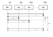
- FIG. 3 is a view schematically showing one configuration example of the battery device shown in FIG.
- Battery device BT includes a plurality of battery banks BK1 to BKn connected in parallel to a DC link, and a plurality of battery management units (BMU: battery management units) CA1 to CAn corresponding to battery banks BK1 to BKn.
- BMU battery management units
- Each of the plurality of battery banks BK1 to BKn includes a plurality of battery modules MDL11 to MDLnm and a current sensor CS.
- the plurality of battery modules MDL11 to MDLnm included in each of the battery banks BNK1 to BNKn are controlled in operation by corresponding battery management circuits CA1 to CAn.
- m (positive integers) battery modules MDL11 to MDL1 m,..., MDLn1 to MDLnm are connected in series, and n (positive integers) battery banks BNK1 ⁇ BNKn are connected in parallel.
- Each of the battery modules MDL11 to MDLnm can be electrically connected to the DC link via, for example, a switch (not shown) such as a contactor.
- the battery management circuits CA1 to CAn can control the switches to switch the electrical connection between the battery banks BK1 to BKn and the DC link.
- Each of the plurality of battery modules MDL11 to MDLnm includes an assembled battery including a plurality of secondary battery cells, and a battery monitoring circuit (CMU: cell monitoring unit) CB11 to CBnm.
- the secondary battery cell is a battery that can be charged and discharged, and is, for example, a lithium ion battery or a nickel hydrogen battery.
- a plurality of battery monitoring circuits CB11 to CBnm included in each of the battery banks BK1 to BKn are communicably connected to common battery management circuits CA1 to CAn via transmission lines.
- each of the plurality of battery monitoring circuits CB11 to CBnm can perform serial communication with the corresponding battery management circuits CA1 to CAn, and the battery monitoring circuits CB11 to CBnm and the battery management circuits CA1 to CAn may be, for example, Communication is performed based on a CAN (control area network) protocol.
- the battery monitoring circuits CB11 to CBnm and the battery management circuits CA1 to CAn may communicate by wired communication means or may communicate by wireless communication means.
- the battery monitoring circuits CB11 to CBnm detect the voltage of the secondary battery cell included in the assembled battery and the temperature in the vicinity of the assembled battery.
- the battery monitoring circuits CB11 to CBnm can output the detected values to the corresponding battery management circuits CA1 to CAn in a predetermined communication cycle ( ⁇ [seconds]).
- the operation of the battery monitoring circuits CB11 to CBnm is controlled by control signals from the battery management circuits CA1 to CAn.
- the current sensors CS1 to CSn detect the currents flowing in the plurality of assembled batteries included in the plurality of battery banks BK1 to BKn, respectively, and supply the values of the detected currents to the corresponding battery management circuits CA1 to CAn.
- the plurality of battery management circuits CA1 to CAn are communicably connected to the vehicle control device CTR via transmission lines.
- the battery management circuits CA1 to CAn and the vehicle control device CTR communicate, for example, based on a CAN (control area network) protocol.
- the plurality of battery management circuits CA1 to CAn and the vehicle control device CTR may communicate with each other by wired communication means, or may communicate with each other by wireless communication means.
- each of the plurality of battery management circuits CA1 to CAn voltage values and temperature values received from the battery monitoring circuits CB11 to CBnm and current values received from the current sensors CS1 to CSn in a predetermined cycle (battery output detection value) Is output to the vehicle control device CTR.
- the plurality of battery management circuits CA1 to CAn are controlled in operation by control signals from the vehicle control device CTR.
- the vehicle control device CTR can calculate internal resistance values of the plurality of secondary battery cells using the voltage values and the current values received from the plurality of battery management circuits CA1 to CAn.
- the vehicle control device CTR acquires an open circuit voltage (OCV) value Vocv of a secondary battery cell, a closed circuit voltage (CCV: close circuit voltage) value Vccv, and a current value I, and a secondary battery Calculate the internal resistance R of the cell.
- OCV open circuit voltage
- CCV close circuit voltage
- I current value
- the internal resistance of the secondary battery cell can be calculated, for example, by the following equation (1).
- R [ ⁇ ] (Vccv-Vocv) / I (1)
- FIG. 4 is a diagram showing an example of a time change of the battery current and the battery voltage when charging the battery module.
- the battery voltage is the open circuit voltage Vocv
- charging of the battery modules MDL11 to MDLnm is started, and when the charging current flows in the assembled battery, the battery voltage is the closed circuit voltage It becomes Vccv.
- the battery modules MDL11 to MDLnm can be charged by the current supplied from the DC link.
- the vehicle control device CTR can convert the power of the internal combustion engine 10 into DC power by the generator 30 and the converter 40 and can supply the DC power to the battery device BT via the DC link. At this time, assuming that the vehicle speed is zero, the power obtained from the internal combustion engine 10 is supplied only to the generator 30 through the power split mechanism 20, and the generator 30 operates in a high speed range.
- the converter 40 When the generator 30 operates in a high speed range, the converter 40 performs over modulation drive or one pulse drive.
- the overmodulation drive is, for example, to make the output command on the alternating current side of the converter 40 a plurality of non-linear square waves synchronized with the carrier period.
- the one-pulse driving is, for example, to set the output command on the alternating current side of the converter 40 as a one-pulse square wave synchronized with the carrier cycle. That is, one pulse drive is a drive mode for controlling converter 40 with one pulse for one cycle, and over modulation drive and asynchronous PWM drive are drive modes for controlling converter 40 with a plurality of pulses for one cycle.
- pulsation occurs in the current flowing in the assembled battery of the battery modules MDL11 to MDLnm Occurs.
- the pulsation of the current is caused, for example, when the difference between the output command value and the actual output voltage value becomes large when the square wave crosses zero, and the pulsation generated in the current is operated by the over modulation drive. It becomes larger when operating by 1 pulse drive than.
- any value may be similarly caused by the pulsation of the current. Since an error is included, the calculation error of the internal resistance value can be suppressed. However, when the timings of detecting the secondary battery cell voltage and the current are not synchronized, there is a possibility that the calculation error of the internal resistance value may become large.
- FIG. 5 is a diagram for explaining an example of communication timing between the battery management circuit and the battery monitoring circuit.
- Each of battery monitoring circuits CBn1 to CBnm periodically detects voltage values of a plurality of secondary battery cells, and transmits the detected value to battery management circuit CAn.
- the cycle in which the plurality of battery monitoring circuits CBn1 to CBnm transmit detected values of the voltages of the plurality of secondary battery cells to the battery management circuit CAn is ⁇ (ms)
- the battery monitoring circuit corresponding to the battery management circuit CAn The time required to complete reception of detection values from all of CBn1 to CBnm is m ⁇ ⁇ (ms).
- each of battery monitoring circuits CBn1 to CBnm it is possible to detect voltages of a plurality of secondary battery cells with substantially no time difference.
- the common battery management circuit CAn when transmitting the voltage value of the secondary battery cell to the common battery management circuit CAn, it is possible to use a communication cycle (up to (m- 1) There is a difference of ⁇ ).
- the number of battery modules MDLn1 to MDLnm controlled by one battery management circuit CAn increases, it is difficult to synchronize the timing of detecting the voltage of the secondary battery cell and the timing of detecting the current.
- pulsation occurs in the charging current of the secondary battery cell in order to avoid the decrease in the calculation accuracy of the internal resistance value of the secondary battery cell. To suppress that.
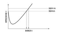
- FIG. 6 is a diagram for explaining an example of the operation of the generator and the converter shown in FIG.
- FIG. 6 shows an example of the relationship between the excitation current of the generator and the line voltage effective value of the AC voltage output from the generator to the converter, with the number of revolutions and the output of the generator fixed.
- the generator 30 is, for example, an induction motor (IM).
- the line voltage effective value is an effective value of the AC voltage applied from the converter 40 to the generator 30.
- the modulation factor is the ratio of the line voltage execution value when the maximum voltage that can be output from the converter 40 to the generator 30 is 100%, and the ratio of the line voltage effective value to the DC voltage between the DC links (% ).
- the line voltage effective value is once decreased and becomes the minimum value, and thereafter, the line voltage effective value becomes larger as the excitation current becomes larger.
- the modulation factor of converter 40 decreases even if the number of revolutions of the generator is the same.
- the modulation factor of converter 40 is adjusted by making the excitation current of generator 30 smaller than normal, and converter 40 The operation with one pulse drive is avoided.
- FIG. 7 is a diagram for explaining an example of the relationship between the generator rotational speed and the method of driving the converter in the hybrid vehicle of the embodiment.
- the vehicle control device CTR detects the closed circuit voltage of a plurality of secondary battery cells in order to measure the internal resistance of the secondary battery cell, it is normal (a period other than when the internal resistance of the secondary battery cells is measured)
- the excitation current of the generator 30 is lowered than in the above to make the modulation factor of the converter 40 smaller, and the converter 40 can be driven by over modulation drive or asynchronous PWM drive.
- the vehicle control device CTR outputs a mode switching command to the converter 40, and in order to change the modulation factor of the converter 40 between the internal resistance measurement time and the normal time, the excitation different from the normal time during the internal resistance measurement
- the current is controlled to be applied to the generator 30.
- Converter 40 switches the magnitude of the excitation current of generator 30 in accordance with the value of the mode switching command.
- the values of the excitation current at the time of internal resistance measurement and the excitation current at the normal time may be values previously set in the converter 40, respectively.
- the rotational speed of the generator 30 when the hybrid vehicle is stopped can also be set in advance. If the excitation current at the time of internal resistance measurement is set so that converter 40 can operate by over modulation drive or asynchronous PWM drive when generator 30 operates at a predetermined rotation speed (for example, N (rpm)) Good.
- the lower limit value of the excitation current of the generator 30 may be set based on the upper limit of the current flowing through the converter 40 (such as the withstand voltage of the switching element).
- the modulation factor of the converter 40 is reduced. From this, the excitation current at the time of internal resistance measurement is set to be smaller than the excitation current at the normal time.
- the vehicle control device CTR sets the value of the torque command of converter 40 in accordance with the rotation speed (rpm) of generator 30.
- Converter 40 calculates the modulation factor based on the mode switching command, the torque command, and the voltage between the DC links, and switches the driving method according to the value of the modulation factor.
- converter 40 operates with asynchronous PWM drive at a modulation rate of less than 75%, operates by overmodulation drive at a modulation rate of 75% or more and less than 100%, and has a modulation rate of 100%. It operates by 1 pulse drive. For example, when the number of revolutions of the generator 30 is N (rpm) at normal times, the modulation factor of the converter 40 is 100%, and the converter 40 operates with one pulse drive. If the excitation current of the generator 30 is reduced and the rotational speed of the generator 30 is N (rpm) while the hybrid vehicle is at a stop, the modulation rate of the converter 40 is 75% or more and less than 100%. Operates by over modulation drive.
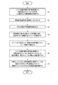
- FIG. 8 is a flow chart for explaining an example of the operation of calculating the internal resistance value of the secondary battery cell in the hybrid vehicle of the embodiment.
- the vehicle control device CTR calculates the internal resistance value of the secondary battery cell when the hybrid vehicle is stopped.
- the vehicle control device CTR acquires open circuit voltages of secondary battery cells included in the plurality of battery modules MDL11 to MDLnm from the plurality of battery management circuits CA1 to CAn of the battery device BT. (Step S1)
- the vehicle control device CTR sets the excitation current of the generator 30 to a value different from that at the normal time. Specifically, the vehicle control device CTR controls the converter 40 in accordance with the mode switching command, and makes the excitation current of the generator 30 smaller than that at the normal time.
- the magnitude of the excitation current of the generator 30 for example, the number of rotations of the generator 30 at the time of calculating the internal resistance value of the secondary battery cell is set in advance, It is set to be modulation drive or asynchronous PWM drive.
- the vehicle control device CTR operates the internal combustion engine 1 so that the hybrid vehicle has a predetermined speed according to the speed command.
- the vehicle control device CTR operates the internal combustion engine 1 so that the hybrid vehicle has a predetermined speed according to the speed command.
- the hybrid vehicle is at a standstill, power generated by the operation of the internal combustion engine 10 is supplied to the generator 30 by the power split mechanism 20.
- the power obtained from the internal combustion engine 10 causes the generator 30 to rotate.
- the vehicle control device CTR acquires the number of revolutions from the generator 30 (or based on a preset number of revolutions), calculates a torque command corresponding to the number of revolutions, and outputs it to the converter 40.
- Converter 40 calculates the modulation factor using the mode switching command, the torque command, and the DC link voltage.
- Converter 40 operates in a driving method according to the modulation factor. At this time, since the excitation current of the generator 30 is smaller than that at the normal time, the modulation factor of the converter 40 with respect to the rotational speed of the generator 30 becomes smaller than at the normal time.
- converter 40 can be operated by asynchronous PWM drive or over modulation drive, and converter 40 can operate at 1 when the internal resistance value of the secondary battery cell is calculated. It is possible to avoid operating by pulse driving. (Step S4)
- the converter 40 converts the AC power supplied from the generator 30 into DC power and supplies it to the DC link.
- the battery device BT is charged by DC power supplied from the DC link.
- Vehicle control device CTR controls the closed circuit voltages of the plurality of secondary battery cells included in the plurality of battery modules MDL11 to MDLnm and the currents flowing in the plurality of battery modules for each of the plurality of battery management circuits CA1 to CAn. Request a value of
- each of the plurality of battery management circuits sequentially acquires the closed circuit voltage of the plurality of secondary battery cells from the plurality of battery modules, and acquires the current flowing in the plurality of battery modules , And outputs the closed circuit voltage value and the current value to the vehicle control device CTR.
- the battery monitoring circuits CB11 to CBnm can obtain closed circuit voltages of a plurality of secondary battery cells substantially simultaneously.
- each of the battery management circuits CA1 to CAn sequentially communicates with the corresponding battery monitoring circuits CB11 to CBnm, and the closed circuit voltages of the secondary battery cells are respectively transmitted from the corresponding battery monitoring circuits CB11 to CBnm.
- a shift arises in the timing which acquires a closed circuit voltage by a communication cycle. For example, when the ripple generated in the charging current of the secondary battery cell becomes large, the magnitude of the current ripple changes depending on the timing of acquiring the closed circuit voltage, and the internal resistance values of the plurality of secondary battery cells can not be calculated accurately .
- Step S7 As described above, according to the hybrid vehicle of the present embodiment, the internal resistance of the secondary battery cell can be accurately calculated.
- the generator 30 was demonstrated as what is an induction motor (IM), you may be a synchronous motor (PM).
- IM induction motor
- PM synchronous motor
- the direction of the excitation current is such as to cancel the magnetic force of the rotor.
Landscapes
- Engineering & Computer Science (AREA)
- Transportation (AREA)
- Mechanical Engineering (AREA)
- Chemical & Material Sciences (AREA)
- Combustion & Propulsion (AREA)
- Automation & Control Theory (AREA)
- Secondary Cells (AREA)
- Electric Propulsion And Braking For Vehicles (AREA)
- Tests Of Electric Status Of Batteries (AREA)
- Hybrid Electric Vehicles (AREA)
Abstract
A vehicle according to an embodiment comprises a battery device (BT) and a control device (CTR). The battery device (BT) is provided with: a plurality of modules (MDL) that are each provided with a battery monitoring circuit (CB) capable of detecting the voltage of each of a plurality of secondary battery cells; current sensors (CS) that detect the current flowing through the plurality of modules (MDL); and battery management circuits (CA) that can acquire the detected current values of the plurality of modules (MDL) and the detected voltage values of the plurality of secondary battery cells. The control device (CTR) uses the open-circuit voltage of the plurality of secondary battery cells, the charging current values of the plurality of battery modules (MDL), and the closed-circuit voltage of the plurality of secondary battery cells to calculate the internal resistance of each of the plurality of secondary battery cells. While the vehicle is stopped, the control device (CTR) decreases the exciting current of a first electric motor (30) until a converter (40) can control the first electric motor (30) with a plurality of pulses in one cycle, charges the plurality of battery modules (MDL) using motive power outputted from the internal combustion engine (10), and acquires the values of the closed-circuit voltage and the charging current.
Description
本発明の実施形態は、ハイブリッド車両に関する。
Embodiments of the present invention relate to hybrid vehicles.
バッテリ装置は、必要な充放電容量に応じて、複数の電池モジュールを直列および並列に接続して構成され得る。複数の電池モジュールのそれぞれは、例えば、複数の二次電池セルを含む組電池と、複数の二次電池セルのそれぞれについて電圧を検出する電池監視回路と、を備えている。
The battery device can be configured by connecting a plurality of battery modules in series and in parallel depending on the required charge and discharge capacity. Each of the plurality of battery modules includes, for example, a battery pack including a plurality of secondary battery cells, and a battery monitoring circuit that detects a voltage for each of the plurality of secondary battery cells.
バッテリ装置は、携帯機器や移動体など、様々な電子機器に電源として搭載されている。例えばハイブリッド車両は、原動機から得られる動力(機械エネルギー)と電動機から得られる電気エネルギーとの少なくとも一方を利用して負荷を駆動することができる。ハイブリッド車両は、例えば2つのインバータを電気的に接続した直流リンクを備え、直流リンクにバッテリ装置を電気的に接続して構成することができる。原動機は、発電機およびインバータを介して直流リンクと電気的に接続している。電動機は、インバータを介して直流リンクと電気的に接続している。
The battery device is mounted as a power supply in various electronic devices such as portable devices and mobile objects. For example, a hybrid vehicle can drive a load using at least one of power (mechanical energy) obtained from a motor and electric energy obtained from a motor. The hybrid vehicle can include, for example, a DC link in which two inverters are electrically connected, and the battery link can be electrically connected to the DC link. The prime mover is electrically connected to the DC link via a generator and an inverter. The motor is electrically connected to the DC link via an inverter.
また、電動機の駆動電圧は、直流リンクから供給される直流電圧を半導体電力スイッチでスイッチングし、任意の振幅、任意の周波数の交流電圧を発生させる電力変換器により供給される。一般的に、スイッチングによる高調波成分の発生を抑制することを目的に、電動機の駆動周波数より十分高いスイッチング周波数を設定し、パルス幅変調(PMW)によりスイッチのゲート信号が生成される。この場合、電力変換器により発生可能な交流電圧の振幅の上限は、直流リンクの線間電圧(直流電圧)の半分となる。
The drive voltage of the motor is supplied by a power converter that switches a DC voltage supplied from the DC link with a semiconductor power switch to generate an AC voltage of an arbitrary amplitude and an arbitrary frequency. Generally, for the purpose of suppressing the generation of harmonic components due to switching, a switching frequency sufficiently higher than the drive frequency of the motor is set, and a gate signal of the switch is generated by pulse width modulation (PMW). In this case, the upper limit of the amplitude of the AC voltage that can be generated by the power converter is half the line voltage (DC voltage) of the DC link.
例えば、高調波成分の抑制を犠牲にして方形波に近い電圧波形を取ると、電力変換器の出力電圧の基本波成分の振幅をさらに大きくすることができる。電力変換器のこの駆動方法は、過変調駆動(同期多パルス駆動)、特に完全に方形波になった状態は1パルス駆動と称されることがある。インバータを過変調駆動および1パルス駆動することにより、直流リンクの線間電圧を変更することなく、駆動電圧を増加させることができ、電動機の高速駆動が可能となる。
For example, if the voltage waveform close to a square wave is taken at the expense of suppression of harmonic components, the amplitude of the fundamental wave component of the output voltage of the power converter can be further increased. This method of driving the power converter may be referred to as over-modulation driving (synchronous multi-pulse driving), in particular a completely square-wave state as single-pulse driving. The drive voltage can be increased without changing the line voltage of the DC link by performing the over modulation drive and the one pulse drive of the inverter, and the motor can be driven at high speed.
二次電池セルは、使用環境や充放電サイクル数などの影響により劣化が進むことが知られている。従来、二次電池セルの内部抵抗に基づいて劣化状態を推定することが提案されている。
It is known that the secondary battery cell is deteriorated by the influence of the use environment and the number of charge and discharge cycles. Conventionally, it has been proposed to estimate the deterioration state based on the internal resistance of the secondary battery cell.
複数の電池監視回路は検出した電圧の値を電池管理回路へ出力する。電池管理回路は、直列に接続した複数の組電池に流れる電流を検出可能である。例えば、複数の二次電池セルの閉回路電圧と組電池に流れる電流との値を用いて内部抵抗を演算する際に、開回路電圧を測定するタイミングと組電池に流れる電流を測定するタイミングとが同期していないと、内部抵抗の演算精度が低下する可能性がある。
The plurality of battery monitoring circuits output the detected voltage values to the battery management circuit. The battery management circuit can detect the current flowing to a plurality of assembled batteries connected in series. For example, when calculating the internal resistance using the values of the closed circuit voltage of the plurality of secondary battery cells and the current flowing to the assembled battery, the timing of measuring the open circuit voltage and the timing of measuring the current flowing to the assembled battery If they are not synchronized, the calculation accuracy of the internal resistance may be reduced.
バッテリ装置の充放電容量が大きくなると、電池管理回路が制御する電池モジュールの数が多くなり、電池管理回路は、複数の電池モジュールの複数の二次電池セルについて閉回路電圧の測定タイミングと、組電池に流れる電流の測定タイミングとを同期させることが困難であった。
As the charge and discharge capacity of the battery device increases, the number of battery modules controlled by the battery management circuit increases, and the battery management circuit determines measurement timings of closed circuit voltages for a plurality of secondary battery cells of a plurality of battery modules and It was difficult to synchronize with the measurement timing of the current flowing in the battery.
本発明の実施形態は上記事情を鑑みて成されたものであって、二次電池セルの内部抵抗を精度よく演算するハイブリッド車両を提供することを目的とする。
The embodiment of the present invention has been made in view of the above circumstances, and an object thereof is to provide a hybrid vehicle that accurately calculates the internal resistance of a secondary battery cell.
本実施形態によるハイブリッド車両は、内燃機関と、第1電動機と、動力結合機構に接続した第2電動機と、前記内燃機関の動力を、前記第1電動機と前記動力結合機構とに分配する動力分割機構と、変調率に応じて駆動方法を切り替えて、前記第1電動機を駆動可能なコンバータと、直流リンクを介して前記コンバータと接続し、前記第2電動機を駆動可能なインバータと、前記動力結合機構から供給されるエネルギーにより回転する車軸と、前記直流リンク間に接続し、複数の二次電池セルを含む組電池と、複数の前記二次電池セルそれぞれの電圧を検出可能な電池監視回路と、を備えた複数の電池モジュールと、複数の前記電池モジュールに流れる電流を検出する電流センサと、複数の前記電池監視回路を制御し、複数の前記電池モジュールに流れる電流の検出値と複数の前記二次電池セルの電圧の検出値とを取得可能な電池管理回路と、を備えた、バッテリ装置と、複数の前記二次電池セルの開回路電圧と、複数の前記電池モジュールの充電電流の値と、複数の前記二次電池セルの閉回路電圧と、を用いて複数の前記二次電池セルそれぞれの内部抵抗を演算する制御装置と、を備え、前記制御装置は、停車しているときに、複数の前記二次電池セルの前記開回路電圧と、前記コンバータが一周期を複数パルスで前記第1電動機を制御可能となるまで前記第1電動機の励磁電流を下げて、前記内燃機関から出力される動力を利用して複数の前記電池モジュールを充電したときの、複数の前記二次電池セルの前記閉回路電圧と、複数の前記電池モジュールの前記充電電流との値を、前記電池管理回路から取得する。
The hybrid vehicle according to the present embodiment comprises: an internal combustion engine, a first electric motor, a second electric motor connected to a power coupling mechanism, and a power split for distributing the power of the internal combustion engine to the first electric motor and the power coupling mechanism. A drive method is switched according to a mechanism and a modulation factor, and a converter capable of driving the first motor, and an inverter capable of driving the second motor by being connected to the converter via a DC link, and the power coupling A battery rotation circuit connected between the DC link, an assembled battery including a plurality of secondary battery cells, and a battery monitoring circuit capable of detecting a voltage of each of the plurality of secondary battery cells; , A plurality of battery modules, a current sensor for detecting a current flowing through the plurality of battery modules, and a plurality of the battery monitoring circuits that control the plurality of battery monitoring circuits. A battery management circuit capable of acquiring a detected value of current flowing in the battery and a detected value of the voltage of the plurality of secondary battery cells, and an open circuit voltage of the plurality of secondary battery cells A controller configured to calculate internal resistances of the plurality of secondary battery cells using values of charging currents of the plurality of battery modules and closed circuit voltages of the plurality of secondary battery cells; The control device controls the first electric motor until the open circuit voltage of the plurality of secondary battery cells and the converter can control the first electric motor with a plurality of pulses per cycle when the vehicle is at a stop. The closed circuit voltage of the plurality of secondary battery cells and the number of the plurality of battery modules when the plurality of battery modules are charged using power output from the internal combustion engine by reducing the excitation current With charge current And it obtains from the battery management circuit.
以下に実施形態のハイブリッド車両について図面を参照して詳細に説明する。
図1は、本実施形態のハイブリッド車両の一構成例を概略的に示すブロック図である。
ハイブリッド車両は、内燃機関10と、動力分割機構20と、発電機(第1電動機)30と、コンバータ40と、インバータ50と、モータ(第2電動機)60と、動力結合機構70と、車軸80と、補機90と、車輪WLと、車両制御装置CTRと、バッテリ装置BTと、を備えている。 The hybrid vehicle of the embodiment will be described in detail below with reference to the drawings.
FIG. 1 is a block diagram schematically showing one configuration example of a hybrid vehicle of the present embodiment.
The hybrid vehicle includes aninternal combustion engine 10, a power split mechanism 20, a generator (first motor) 30, a converter 40, an inverter 50, a motor (second motor) 60, a power coupling mechanism 70, and an axle 80. , An accessory 90, a wheel WL, a vehicle control device CTR, and a battery device BT.
図1は、本実施形態のハイブリッド車両の一構成例を概略的に示すブロック図である。
ハイブリッド車両は、内燃機関10と、動力分割機構20と、発電機(第1電動機)30と、コンバータ40と、インバータ50と、モータ(第2電動機)60と、動力結合機構70と、車軸80と、補機90と、車輪WLと、車両制御装置CTRと、バッテリ装置BTと、を備えている。 The hybrid vehicle of the embodiment will be described in detail below with reference to the drawings.
FIG. 1 is a block diagram schematically showing one configuration example of a hybrid vehicle of the present embodiment.
The hybrid vehicle includes an
内燃機関10は、ガソリンエンジンやディーゼルエンジン等、ハイブリッド車両を駆動する機械エネルギーを生成する原動機である。
動力分割機構20は、内燃機関10で生成された機械エネルギーを、発電機30側に供給されるエネルギーと、車輪WL側(車軸80側)に供給されるエネルギーとに分配する三軸動力分割機構である。 Theinternal combustion engine 10 is a prime mover that generates mechanical energy for driving a hybrid vehicle, such as a gasoline engine or a diesel engine.
Power split device 20 divides the mechanical energy generated by internal combustion engine 10 into energy to be supplied to generator 30 and energy to be supplied to wheel WL side (axle 80 side). It is.
動力分割機構20は、内燃機関10で生成された機械エネルギーを、発電機30側に供給されるエネルギーと、車輪WL側(車軸80側)に供給されるエネルギーとに分配する三軸動力分割機構である。 The
動力分割機構20は、例えば遊星歯車(図示せず)であって、サンギアSと、サンギアSに外接したプラネタリアギアPと、プラネタリアギアPが内接したリングギアRと、プラネタリアギアPの軌道に沿って回転するプラネタリキャリアCと、を備えている。本実施形態では、プラネタリキャリアCは、内燃機関10で生成された機械エネルギーにより回転する。サンギアSの回転動力は発電機30へ伝達される。リングギアRの回転動力は車軸80と接続した動力結合機構70に伝達される。リングギアRの回転数(rpm)は車速に比例する。
The power split mechanism 20 is, for example, a planetary gear (not shown), and includes a sun gear S, a planetary rear gear P circumscribed to the sun gear S, a ring gear R to which the planetary rear gear P internally contacts, and a planetary rear gear P And a planetary carrier C rotating along. In the present embodiment, the planetary carrier C is rotated by the mechanical energy generated by the internal combustion engine 10. The rotational power of the sun gear S is transmitted to the generator 30. The rotational power of the ring gear R is transmitted to a power coupling mechanism 70 connected to the axle 80. The rotational speed (rpm) of the ring gear R is proportional to the vehicle speed.
図2は、動力分割機構の動作の一例を説明するための図である。
動力分割機構20の動作は、サンギアSとリングギアRとのギア比により決まる。この例では、サンギアSのギア数Zsとリングギアのギア数Zrとの比はZs:Zr=1:2である。例えば、車速がゼロであるときリングギアの回転数はゼロ(rpm)である。このとき、プラネタリアキャリアの回転数が1000(rpm)であれば、サンギアの回転数がプラネタリアキャリアの3倍の3000(rpm)となり、発電機30が高速域で動作することとなる。 FIG. 2 is a diagram for explaining an example of the operation of the power split mechanism.
The operation of thepower split mechanism 20 is determined by the gear ratio between the sun gear S and the ring gear R. In this example, the ratio of the gear number Zs of the sun gear S to the gear number Zr of the ring gear is Zs: Zr = 1: 2. For example, when the vehicle speed is zero, the rotation speed of the ring gear is zero (rpm). At this time, if the rotation speed of the planetaria carrier is 1000 (rpm), the rotation speed of the sun gear is 3000 rpm, which is three times the rotation speed of the planetaria carrier, and the generator 30 operates in the high speed region.
動力分割機構20の動作は、サンギアSとリングギアRとのギア比により決まる。この例では、サンギアSのギア数Zsとリングギアのギア数Zrとの比はZs:Zr=1:2である。例えば、車速がゼロであるときリングギアの回転数はゼロ(rpm)である。このとき、プラネタリアキャリアの回転数が1000(rpm)であれば、サンギアの回転数がプラネタリアキャリアの3倍の3000(rpm)となり、発電機30が高速域で動作することとなる。 FIG. 2 is a diagram for explaining an example of the operation of the power split mechanism.
The operation of the
発電機30は、動力分割機構20から供給される動力により交流電力を発電し、コンバータ40へ出力可能であり、コンバータ40から供給される交流電力により回転駆動される誘導電動機(IM)である。発電機30は、例えば回転数を検出する検出器(図示せず)を備えている。発電機30の回転数は、車両制御装置CTRに供給される。
The generator 30 is an induction motor (IM) that generates AC power by the power supplied from the power split mechanism 20 and can output the generated AC power to the converter 40, and is rotationally driven by the AC power supplied from the converter 40. The generator 30 includes, for example, a detector (not shown) that detects the number of revolutions. The rotation speed of the generator 30 is supplied to the vehicle control device CTR.
コンバータ40は電力変換器であって、発電機30から出力された3相交流電力を直流電力に変換して直流リンクへ出力可能であって、直流リンクから供給される直流電力を3相交流電力に変換して発電機30へ出力可能である。コンバータ40は直流リンクを介してインバータ50、バッテリ装置BTおよび補機90と電気的に接続している。
The converter 40 is a power converter, which can convert three-phase AC power output from the generator 30 into DC power and can output the DC power to the DC link, and can convert DC power supplied from the DC link into three-phase AC power And can be output to the generator 30. Converter 40 is electrically connected to inverter 50, battery device BT and accessory 90 via a DC link.
コンバータ40は、車両制御装置CTRからモード切替指令とトルク指令とを受信する。コンバータ40は、モード切替指令にしたがって発電機30の励磁電流の値を調整可能である。コンバータ40は、トルク指令を実現するように発電機30を動作させる。
Converter 40 receives a mode switching command and a torque command from vehicle control device CTR. Converter 40 can adjust the value of the excitation current of generator 30 in accordance with the mode switching command. The converter 40 operates the generator 30 to realize the torque command.
インバータ50は電力変換器であって、直流リンクから供給された直流電力を交流電力に変換してモータ60へ出力可能である。また、インバータ50は、モータ60から供給された交流電力を直流電力に変換して直流リンクへ出力可能である。インバータ50は車両制御装置CTRからトルク指令を受信する。インバータ50は、受信したトルク指令を実現するようにモータ60へ交流電力を出力する。
The inverter 50 is a power converter, and can convert DC power supplied from the DC link into AC power and output the AC power to the motor 60. Further, the inverter 50 can convert AC power supplied from the motor 60 into DC power and can output it to the DC link. Inverter 50 receives a torque command from vehicle control device CTR. Inverter 50 outputs AC power to motor 60 so as to realize the received torque command.
モータ60は、インバータ50から供給される交流電力により駆動される電動機であって、電気エネルギーを機械エネルギーに変換して動力結合機構70へ出力する。
動力結合機構70は、動力分割機構20のリングギアRから伝達された機械エネルギーと、インバータ50から供給された機械エネルギーとを合成したエネルギーを車軸80へ伝達する。車輪WLは車軸80を介して回転駆動される。 Themotor 60 is a motor driven by AC power supplied from the inverter 50, and converts electrical energy into mechanical energy and outputs the mechanical energy to the power coupling mechanism 70.
Thepower coupling mechanism 70 transmits, to the axle 80, energy obtained by combining the mechanical energy transmitted from the ring gear R of the power split mechanism 20 and the mechanical energy supplied from the inverter 50. The wheel WL is rotationally driven via the axle 80.
動力結合機構70は、動力分割機構20のリングギアRから伝達された機械エネルギーと、インバータ50から供給された機械エネルギーとを合成したエネルギーを車軸80へ伝達する。車輪WLは車軸80を介して回転駆動される。 The
The
バッテリ装置BTは、直流リンクから供給される電力により充電可能であり、直流リンクへ電力を放電可能である。バッテリ装置BTは、遮断器(図示せず)を介して直流リンクと電気的に接続している。遮断器は例えば電磁接触器であって、車両制御回路CTRにより動作を制御される。
The battery device BT can be charged by the power supplied from the DC link, and can discharge the power to the DC link. The battery device BT is electrically connected to the DC link via a circuit breaker (not shown). The circuit breaker is, for example, a magnetic contactor whose operation is controlled by the vehicle control circuit CTR.
補機90は、例えば照明装置など、ハイブリッド車両内に搭載された負荷を含む。補機90は直流リンクを介してバッテリ装置BT、コンバータ40、および、インバータ50と接続し、直流リンクから供給されるエネルギーにより駆動される。補機90は、消費電力を検出して車両制御装置CTRへ出力する。
Accessory 90 includes a load mounted in the hybrid vehicle, such as a lighting device, for example. The accessory 90 is connected to the battery device BT, the converter 40, and the inverter 50 via the direct current link, and is driven by the energy supplied from the direct current link. Auxiliary equipment 90 detects the power consumption and outputs it to the vehicle control device CTR.
車両制御装置CTRは、外部から供給される牽引力指令に従って、内燃機関10、発電機30、コンバータ40、インバータ50、モータ60、および、バッテリ装置BTが互いに連係して動作するように制御する上位制御装置である。車両制御装置CTRは、例えば、CPU(central processing unit)やMPU(micro processing unit)などのプロセッサを少なくとも1つと、メモリとを備える演算回路である。
The vehicle control device CTR controls the internal combustion engine 10, the generator 30, the converter 40, the inverter 50, the motor 60, and the battery device BT to operate in cooperation with each other according to a traction force command supplied from the outside. It is an apparatus. The vehicle control device CTR is an arithmetic circuit including, for example, at least one processor such as a central processing unit (CPU) or a micro processing unit (MPU), and a memory.
車両制御装置CTRは、例えばハイブリッド車両が停車しているときに、バッテリ装置BTに含まれる複数の二次電池セルの内部抵抗値を演算可能に構成されている。車両制御装置CTRは、複数の二次電池セルの内部抵抗値を利用して、例えば、バッテリ装置BTの劣化度を判断することが可能である。車両制御装置CTRは、メモリに記録されたプログラムを実行することにより、複数の二次電池セルの内部抵抗を演算する動作を行ってもよい。
The vehicle control device CTR is configured to be able to calculate internal resistance values of a plurality of secondary battery cells included in the battery device BT, for example, when the hybrid vehicle is stopped. The vehicle control device CTR can determine, for example, the degree of deterioration of the battery device BT using the internal resistance values of the plurality of secondary battery cells. The vehicle control device CTR may operate to calculate the internal resistances of the plurality of secondary battery cells by executing the program stored in the memory.
図3は、図1に示すバッテリ装置の一構成例を概略的に示す図である。
バッテリ装置BTは、直流リンクに並列に接続した複数のバッテリバンクBK1~BKnと、バッテリバンクBK1~BKnに対応した複数の電池管理回路(BMU:battery management unit)CA1~CAnと、を備えている。複数のバッテリバンクBK1~BKnのそれぞれは、複数の電池モジュールMDL11~MDLnmと、電流センサCSと、を備えている。 FIG. 3 is a view schematically showing one configuration example of the battery device shown in FIG.
Battery device BT includes a plurality of battery banks BK1 to BKn connected in parallel to a DC link, and a plurality of battery management units (BMU: battery management units) CA1 to CAn corresponding to battery banks BK1 to BKn. . Each of the plurality of battery banks BK1 to BKn includes a plurality of battery modules MDL11 to MDLnm and a current sensor CS.
バッテリバンクBNK1~BNKnのそれぞれに含まれる複数の電池モジュールMDL11~MDLnmは、対応する電池管理回路CA1~CAnにより動作を制御される。本実施形態では、バッテリバンクBNK1~BNKnのそれぞれにおいて、m(正の整数)個の電池モジュールMDL11~MDL1m、…、MDLn1~MDLnmが直列に接続し、n(正の整数)個のバッテリバンクBNK1~BNKnが並列に接続している。
The plurality of battery modules MDL11 to MDLnm included in each of the battery banks BNK1 to BNKn are controlled in operation by corresponding battery management circuits CA1 to CAn. In this embodiment, in each of the battery banks BNK1 to BNKn, m (positive integers) battery modules MDL11 to MDL1 m,..., MDLn1 to MDLnm are connected in series, and n (positive integers) battery banks BNK1 ~ BNKn are connected in parallel.
電池モジュールMDL11~MDLnmのそれぞれは、例えば、コンタクタ等の切替器(図示せず)を介して直流リンクと電気的に接続可能である。電池管理回路CA1~CAnは、切替器を制御してバッテリバンクBK1~BKnと直流リンクとの電気的接続を切替えることができる。
Each of the battery modules MDL11 to MDLnm can be electrically connected to the DC link via, for example, a switch (not shown) such as a contactor. The battery management circuits CA1 to CAn can control the switches to switch the electrical connection between the battery banks BK1 to BKn and the DC link.
複数の電池モジュールMDL11~MDLnmのそれぞれは、複数の二次電池セルを含む組電池と、電池監視回路(CMU:cell monitoring unit)CB11~CBnmと、を備えている。
二次電池セルは、充電および放電可能な電池であって、例えば、リチウムイオン電池や、ニッケル水素電池である。 Each of the plurality of battery modules MDL11 to MDLnm includes an assembled battery including a plurality of secondary battery cells, and a battery monitoring circuit (CMU: cell monitoring unit) CB11 to CBnm.
The secondary battery cell is a battery that can be charged and discharged, and is, for example, a lithium ion battery or a nickel hydrogen battery.
バッテリバンクBK1~BKnのそれぞれに含まれる複数の電池監視回路CB11~CBnmは、伝送ラインを介して共通の電池管理回路CA1~CAnと通信可能に接続されている。本実施形態では、複数の電池監視回路CB11~CBnmそれぞれは、対応する電池管理回路CA1~CAnとシリアル通信を行うことができ、電池監視回路CB11~CBnmと電池管理回路CA1~CAnとは、例えばCAN(control area network)プロトコルに基づいて通信を行う。なお、電池監視回路CB11~CBnmと電池管理回路CA1~CAnとは、有線の通信手段により通信を行ってもよく、無線の通信手段により通信を行ってもよい。
A plurality of battery monitoring circuits CB11 to CBnm included in each of the battery banks BK1 to BKn are communicably connected to common battery management circuits CA1 to CAn via transmission lines. In the present embodiment, each of the plurality of battery monitoring circuits CB11 to CBnm can perform serial communication with the corresponding battery management circuits CA1 to CAn, and the battery monitoring circuits CB11 to CBnm and the battery management circuits CA1 to CAn may be, for example, Communication is performed based on a CAN (control area network) protocol. The battery monitoring circuits CB11 to CBnm and the battery management circuits CA1 to CAn may communicate by wired communication means or may communicate by wireless communication means.
電池監視回路CB11~CBnmは、組電池に含まれる二次電池セルの電圧と、組電池の近傍の温度と、を検出する。電池監視回路CB11~CBnmは、所定の通信周期(α[秒])で、検出した値を対応する電池管理回路CA1~CAnへ出力可能である。また、電池監視回路CB11~CBnmは、電池管理回路CA1~CAnからの制御信号により動作を制御される。
The battery monitoring circuits CB11 to CBnm detect the voltage of the secondary battery cell included in the assembled battery and the temperature in the vicinity of the assembled battery. The battery monitoring circuits CB11 to CBnm can output the detected values to the corresponding battery management circuits CA1 to CAn in a predetermined communication cycle (α [seconds]). The operation of the battery monitoring circuits CB11 to CBnm is controlled by control signals from the battery management circuits CA1 to CAn.
電流センサCS1~CSnは、複数のバッテリバンクBK1~BKnそれぞれに含まれる複数の組電池に流れる電流を検出し、検出した電流の値を対応する電池管理回路CA1~CAnへ供給する。
The current sensors CS1 to CSn detect the currents flowing in the plurality of assembled batteries included in the plurality of battery banks BK1 to BKn, respectively, and supply the values of the detected currents to the corresponding battery management circuits CA1 to CAn.
複数の電池管理回路CA1~CAnは、伝送ラインを介して車両制御装置CTRと通信可能に接続されている。本実施形態では、電池管理回路CA1~CAnと車両制御装置CTRとは、例えばCAN(control area network)プロトコルに基づいて通信を行う。なお、複数の電池管理回路CA1~CAnと車両制御装置CTRとは、有線の通信手段により通信を行ってもよく、無線の通信手段により通信を行ってもよい。
The plurality of battery management circuits CA1 to CAn are communicably connected to the vehicle control device CTR via transmission lines. In the present embodiment, the battery management circuits CA1 to CAn and the vehicle control device CTR communicate, for example, based on a CAN (control area network) protocol. The plurality of battery management circuits CA1 to CAn and the vehicle control device CTR may communicate with each other by wired communication means, or may communicate with each other by wireless communication means.
複数の電池管理回路CA1~CAnのそれぞれは、所定の周期で、電池監視回路CB11~CBnmから受信した電圧値および温度値と、電流センサCS1~CSnから受信した電流値と(バッテリ出力検出値)を車両制御装置CTRへ出力する。複数の電池管理回路CA1~CAnは、車両制御装置CTRからの制御信号により動作を制御される。
In each of the plurality of battery management circuits CA1 to CAn, voltage values and temperature values received from the battery monitoring circuits CB11 to CBnm and current values received from the current sensors CS1 to CSn in a predetermined cycle (battery output detection value) Is output to the vehicle control device CTR. The plurality of battery management circuits CA1 to CAn are controlled in operation by control signals from the vehicle control device CTR.
車両制御装置CTRは、複数の電池管理回路CA1~CAnから受信した電圧値と電流値とを用いて、複数の二次電池セルの内部抵抗値を演算することができる。車両制御装置CTRは、二次電池セルの開回路電圧(OCV:open circuit voltage)値Vocvと、閉回路電圧(CCV:close circuit voltage)値Vccvと、電流値Iとを取得し、二次電池セルの内部抵抗Rを演算する。二次電池セルの内部抵抗は、例えば下記式(1)により演算することができる。
R[Ω]=(Vccv-Vocv)/I…(1) The vehicle control device CTR can calculate internal resistance values of the plurality of secondary battery cells using the voltage values and the current values received from the plurality of battery management circuits CA1 to CAn. The vehicle control device CTR acquires an open circuit voltage (OCV) value Vocv of a secondary battery cell, a closed circuit voltage (CCV: close circuit voltage) value Vccv, and a current value I, and a secondary battery Calculate the internal resistance R of the cell. The internal resistance of the secondary battery cell can be calculated, for example, by the following equation (1).
R [Ω] = (Vccv-Vocv) / I (1)
図4は、電池モジュールを充電しているときのバッテリ電流とバッテリ電圧との時間変化の一例を示す図である。
電池モジュールMDL11~MDLnmが充電および放電されていない状態ではバッテリ電圧は開回路電圧Vocvであって、電池モジュールMDL11~MDLnmの充電が開始され、組電池に充電電流が流れるとバッテリ電圧が閉回路電圧Vccvとなる。 FIG. 4 is a diagram showing an example of a time change of the battery current and the battery voltage when charging the battery module.
When the battery modules MDL11 to MDLnm are not charged and discharged, the battery voltage is the open circuit voltage Vocv, charging of the battery modules MDL11 to MDLnm is started, and when the charging current flows in the assembled battery, the battery voltage is the closed circuit voltage It becomes Vccv.
電池モジュールMDL11~MDLnmは直流リンクから供給される電流により充電することができる。
The battery modules MDL11 to MDLnm can be charged by the current supplied from the DC link.
車両制御装置CTRは、内燃機関10の動力を発電機30とコンバータ40とで直流電力に変換して直流リンクを介してバッテリ装置BTへ供給することができる。このとき、車速をゼロとすると、内燃機関10から得られる動力は動力分割機構20を介して発電機30のみに供給され、発電機30を高速域で動作することとなる。
The vehicle control device CTR can convert the power of the internal combustion engine 10 into DC power by the generator 30 and the converter 40 and can supply the DC power to the battery device BT via the DC link. At this time, assuming that the vehicle speed is zero, the power obtained from the internal combustion engine 10 is supplied only to the generator 30 through the power split mechanism 20, and the generator 30 operates in a high speed range.
発電機30が高速域で動作するときには、コンバータ40は過変調駆動又は1パルス駆動を行う。過変調駆動は、例えば、コンバータ40の交流側の出力指令をキャリア周期に同期した非線形の複数の方形波とするものである。1パルス駆動は、例えば、コンバータ40の交流側の出力指令をキャリア周期に同期した1パルスの方形波とするものである。すなわち、1パルス駆動は、一周期を1パルスでコンバータ40を制御する駆動モードであり、過変調駆動と非同期PWM駆動は、一周期を複数パルスでコンバータ40を制御する駆動モードである。
When the generator 30 operates in a high speed range, the converter 40 performs over modulation drive or one pulse drive. The overmodulation drive is, for example, to make the output command on the alternating current side of the converter 40 a plurality of non-linear square waves synchronized with the carrier period. The one-pulse driving is, for example, to set the output command on the alternating current side of the converter 40 as a one-pulse square wave synchronized with the carrier cycle. That is, one pulse drive is a drive mode for controlling converter 40 with one pulse for one cycle, and over modulation drive and asynchronous PWM drive are drive modes for controlling converter 40 with a plurality of pulses for one cycle.
過変調駆動又は1パルス駆動を行うと、バッテリ装置BTに対して充電電流および充電電流が一定となるように発電機30を制御しても、電池モジュールMDL11~MDLnmの組電池に流れる電流に脈動が発生する。この電流の脈動は、例えば方形波がゼロクロスするときに、出力指令値と実際の出力電圧値との差が大きくなることにより生じるものであって電流に生じる脈動は、過変調駆動で動作するときよりも1パルス駆動で動作するときの方が大きくなる。
When over modulation drive or one pulse drive is performed, even if the generator 30 is controlled so that the charging current and the charging current become constant with respect to the battery device BT, pulsation occurs in the current flowing in the assembled battery of the battery modules MDL11 to MDLnm Occurs. The pulsation of the current is caused, for example, when the difference between the output command value and the actual output voltage value becomes large when the square wave crosses zero, and the pulsation generated in the current is operated by the over modulation drive. It becomes larger when operating by 1 pulse drive than.
上記のように発電機30が高速域で動作しているとき、二次電池セルの電圧と電流とを検出するタイミングが同期している場合は、いずれの値にも同様に電流の脈動分による誤差が含まれるため、内部抵抗値の演算誤差が抑えられる。しかしながら、二次電池セル電圧と電流とを検出するタイミングの同期がとれていない場合、内部抵抗値の演算誤差が大きくなる可能性がある。
As described above, when the generator 30 is operating in the high speed range, when the timings of detecting the voltage and current of the secondary battery cell are synchronized, any value may be similarly caused by the pulsation of the current. Since an error is included, the calculation error of the internal resistance value can be suppressed. However, when the timings of detecting the secondary battery cell voltage and the current are not synchronized, there is a possibility that the calculation error of the internal resistance value may become large.
二次電池セル電圧と電流とを検出するタイミングの同期がとれず、例えば、バッテリ電流を検出したタイミングにて電流の脈動分Irippleが最大であり、二次電池セル電圧を検出したタイミングにて二次電池セル電圧の脈動分(=R(二次電池セルの内部抵抗)×Iripple)が最小であった場合、内部抵抗値の演算誤差が大きくなり、演算精度が低下してしまう。
The timing to detect the secondary battery cell voltage and current can not be synchronized, for example, the ripple Iripple of the current is maximum at the timing at which the battery current is detected, and two at the timing at which the secondary battery cell voltage is detected. If the pulsation of the next battery cell voltage (= R (internal resistance of the secondary battery cell) × Iripple) is minimum, the calculation error of the internal resistance value will be large, and the calculation accuracy will be reduced.
図5は、電池管理回路と電池監視回路との通信タイミングの一例を説明するための図である。
電池監視回路CBn1~CBnmのそれぞれは、周期的に複数の二次電池セルの電圧値を検出し電池管理回路CAnへ検出値を送信する。複数の電池監視回路CBn1~CBnmが、複数の二次電池セルの電圧の検出値を電池管理回路CAnへ送信する周期はα(ms)であるとすると、電池管理回路CAnが対応する電池監視回路CBn1~CBnm全てから検出値の受信を完了するまでに要する時間はm×α(ms)となる。 FIG. 5 is a diagram for explaining an example of communication timing between the battery management circuit and the battery monitoring circuit.
Each of battery monitoring circuits CBn1 to CBnm periodically detects voltage values of a plurality of secondary battery cells, and transmits the detected value to battery management circuit CAn. Assuming that the cycle in which the plurality of battery monitoring circuits CBn1 to CBnm transmit detected values of the voltages of the plurality of secondary battery cells to the battery management circuit CAn is α (ms), the battery monitoring circuit corresponding to the battery management circuit CAn The time required to complete reception of detection values from all of CBn1 to CBnm is m × α (ms).
電池監視回路CBn1~CBnmのそれぞれにおいて、複数の二次電池セルの電圧は略時間差なく検出することが可能である。しかしながら、共通の電池管理回路CAnへ二次電池セルの電圧値を送信する場合、電池監視回路CBn1~CBnm間で、二次電池セルの電圧を検出するタイミングに通信周期分(最大で(m-1)α)の差が生じる。1つの電池管理回路CAnにより制御される電池モジュールMDLn1~MDLnmの数が多くなると、二次電池セルの電圧を検出するタイミングと電流を検出するタイミングとを同期させることが困難であった。
In each of battery monitoring circuits CBn1 to CBnm, it is possible to detect voltages of a plurality of secondary battery cells with substantially no time difference. However, when transmitting the voltage value of the secondary battery cell to the common battery management circuit CAn, it is possible to use a communication cycle (up to (m- 1) There is a difference of α). When the number of battery modules MDLn1 to MDLnm controlled by one battery management circuit CAn increases, it is difficult to synchronize the timing of detecting the voltage of the secondary battery cell and the timing of detecting the current.
本実施形態では、二次電池セルの内部抵抗値の演算精度が低下することを回避するために、二次電池セルの内部抵抗を演算する際に、二次電池セルの充電電流に脈動が生じることを抑制している。
In the present embodiment, when calculating the internal resistance of the secondary battery cell, pulsation occurs in the charging current of the secondary battery cell in order to avoid the decrease in the calculation accuracy of the internal resistance value of the secondary battery cell. To suppress that.
図6は、図1に示す発電機およびコンバータの動作の一例を説明するための図である。
図6では、発電機の回転数と出力とを一定とし、発電機の励磁電流と発電機からコンバータへ出力される交流電圧の線間電圧実効値との関係の一例を示している。 FIG. 6 is a diagram for explaining an example of the operation of the generator and the converter shown in FIG.
FIG. 6 shows an example of the relationship between the excitation current of the generator and the line voltage effective value of the AC voltage output from the generator to the converter, with the number of revolutions and the output of the generator fixed.
なおこの例では、発電機30は、例えば誘導電動機(IM)である。線間電圧実効値は、コンバータ40から発電機30に印加される交流電圧の実効値である。変調率は、コンバータ40から発電機30へ出力可能な最大電圧を100%としたときの線間電圧実行値の比率であって、直流リンク間の直流電圧に対する線間電圧実効値の割合(%)である。
In this example, the generator 30 is, for example, an induction motor (IM). The line voltage effective value is an effective value of the AC voltage applied from the converter 40 to the generator 30. The modulation factor is the ratio of the line voltage execution value when the maximum voltage that can be output from the converter 40 to the generator 30 is 100%, and the ratio of the line voltage effective value to the DC voltage between the DC links (% ).
発電機30の励磁電流をゼロから大きくなるように変化させると、線間電圧実効値は一度低下して最小値となり、その後は励磁電流が大きいほど線間電圧実効値は大きくなる。線間電圧実効値の極小値よりも大きい領域では、励磁電流が小さくなると、発電機の回転数が同じであってもコンバータ40の変調率は小さくなる。
When the excitation current of the generator 30 is changed so as to increase from zero, the line voltage effective value is once decreased and becomes the minimum value, and thereafter, the line voltage effective value becomes larger as the excitation current becomes larger. In a region larger than the minimum value of the line voltage effective value, when the excitation current decreases, the modulation factor of converter 40 decreases even if the number of revolutions of the generator is the same.
この例によれば、発電機30の回転数と出力とが一定であるときに、発電機30の励磁電流の大きさを調整することにより、コンバータ40の変調率を調整することが可能であることが分かる。
According to this example, it is possible to adjust the modulation factor of converter 40 by adjusting the magnitude of the excitation current of generator 30 when the rotation speed and output of generator 30 are constant. I understand that.
そこで、本実施形態のハイブリッド車両では、二次電池セルの内部抵抗を測定する際に、発電機30の励磁電流を通常時よりも小さくすることによりコンバータ40の変調率を調整し、コンバータ40が1パルス駆動で動作することを回避している。
Therefore, in the hybrid vehicle of the present embodiment, when measuring the internal resistance of the secondary battery cell, the modulation factor of converter 40 is adjusted by making the excitation current of generator 30 smaller than normal, and converter 40 The operation with one pulse drive is avoided.
図7は、実施形態のハイブリッド車両において、発電機回転数とコンバータの駆動方法との関係の一例を説明するための図である。
車両制御装置CTRは、二次電池セルの内部抵抗を測定するために複数の二次電池セルの閉回路電圧を検出するときには、通常時(二次電池セルの内部抵抗を測定するとき以外の期間)よりも発電機30の励磁電流を下げて、コンバータ40の変調率を小さくし、過変調駆動や非同期PWM駆動によりコンバータ40を駆動可能とする。 FIG. 7 is a diagram for explaining an example of the relationship between the generator rotational speed and the method of driving the converter in the hybrid vehicle of the embodiment.
When the vehicle control device CTR detects the closed circuit voltage of a plurality of secondary battery cells in order to measure the internal resistance of the secondary battery cell, it is normal (a period other than when the internal resistance of the secondary battery cells is measured) The excitation current of thegenerator 30 is lowered than in the above to make the modulation factor of the converter 40 smaller, and the converter 40 can be driven by over modulation drive or asynchronous PWM drive.
車両制御装置CTRは、二次電池セルの内部抵抗を測定するために複数の二次電池セルの閉回路電圧を検出するときには、通常時(二次電池セルの内部抵抗を測定するとき以外の期間)よりも発電機30の励磁電流を下げて、コンバータ40の変調率を小さくし、過変調駆動や非同期PWM駆動によりコンバータ40を駆動可能とする。 FIG. 7 is a diagram for explaining an example of the relationship between the generator rotational speed and the method of driving the converter in the hybrid vehicle of the embodiment.
When the vehicle control device CTR detects the closed circuit voltage of a plurality of secondary battery cells in order to measure the internal resistance of the secondary battery cell, it is normal (a period other than when the internal resistance of the secondary battery cells is measured) The excitation current of the
具体的には、車両制御装置CTRは、コンバータ40へモード切替指令を出力し、内部抵抗測定時と通常時とでコンバータ40の変調率を変えるために、内部抵抗測定時には通常時とは異なる励磁電流が発電機30に印加されるように制御する。
Specifically, the vehicle control device CTR outputs a mode switching command to the converter 40, and in order to change the modulation factor of the converter 40 between the internal resistance measurement time and the normal time, the excitation different from the normal time during the internal resistance measurement The current is controlled to be applied to the generator 30.
コンバータ40は、モード切替指令の値に従って発電機30の励磁電流の大きさを切替える。内部抵抗測定時の励磁電流と通常時の励磁電流との値は、それぞれ予めコンバータ40に設定された値でもよい。車両制御装置CTRにおいて、内部抵抗測定時における内燃機関10の速度指令を予め設定すると、ハイブリッド車両が停車しているとしたときの発電機30の回転数も予め設定可能である。発電機30が所定の回転数(例えばN(rpm))で動作するときに、過変調駆動或いは非同期PWM駆動によりコンバータ40が動作可能となるように、内部抵抗測定時の励磁電流を設定すればよい。
Converter 40 switches the magnitude of the excitation current of generator 30 in accordance with the value of the mode switching command. The values of the excitation current at the time of internal resistance measurement and the excitation current at the normal time may be values previously set in the converter 40, respectively. In the vehicle control device CTR, when the speed command of the internal combustion engine 10 at the time of internal resistance measurement is set in advance, the rotational speed of the generator 30 when the hybrid vehicle is stopped can also be set in advance. If the excitation current at the time of internal resistance measurement is set so that converter 40 can operate by over modulation drive or asynchronous PWM drive when generator 30 operates at a predetermined rotation speed (for example, N (rpm)) Good.
なお、発電機30の回転数と出力とが一定であるとき、励磁電流を小さくすると線間電圧実効値が小さくなり、コンバータ40に流れる電流が大きくなる。したがって、発電機30の励磁電流の下限値は、コンバータ40に流れる電流の上限(スイッチング素子の耐圧等)に基づいて設定してもよい。
When the number of revolutions and the output of the generator 30 are constant, reducing the exciting current reduces the effective value of the line voltage, and the current flowing through the converter 40 increases. Therefore, the lower limit value of the excitation current of the generator 30 may be set based on the upper limit of the current flowing through the converter 40 (such as the withstand voltage of the switching element).
発電機30の回転数と出力とが一定であるとき、発電機30の励磁電流を小さくすると、コンバータ40の変調率は小さくなる。このことから、内部抵抗測定時の励磁電流は、通常時の励磁電流よりも小さくなるように設定される。
When the number of revolutions and the output of the generator 30 are constant, and the excitation current of the generator 30 is reduced, the modulation factor of the converter 40 is reduced. From this, the excitation current at the time of internal resistance measurement is set to be smaller than the excitation current at the normal time.
車両制御装置CTRは、発電機30の回転数(rpm)に応じてコンバータ40のトルク指令の値を設定する。コンバータ40は、モード切替指令とトルク指令と直流リンク間の電圧とに基づいて変調率を演算し、変調率の値に応じて駆動方法を切替える。
The vehicle control device CTR sets the value of the torque command of converter 40 in accordance with the rotation speed (rpm) of generator 30. Converter 40 calculates the modulation factor based on the mode switching command, the torque command, and the voltage between the DC links, and switches the driving method according to the value of the modulation factor.
図7に示す例では、コンバータ40は、変調率が75%未満において非同期PWM駆動により動作し、変調率が75%以上100%未満において過変調駆動により動作し、変調率が100%のときに1パルス駆動により動作する。
例えば、通常時に発電機30の回転数をN(rpm)としたとき、コンバータ40の変調率は100%であり、コンバータ40は1パルス駆動にて動作する。ハイブリッド車両が停車しているときに、発電機30の励磁電流を小さくし、発電機30の回転数をN(rpm)とすると、コンバータ40の変調率は75%以上100%未満となり、コンバータ40は過変調駆動により動作する。 In the example shown in FIG. 7,converter 40 operates with asynchronous PWM drive at a modulation rate of less than 75%, operates by overmodulation drive at a modulation rate of 75% or more and less than 100%, and has a modulation rate of 100%. It operates by 1 pulse drive.
For example, when the number of revolutions of thegenerator 30 is N (rpm) at normal times, the modulation factor of the converter 40 is 100%, and the converter 40 operates with one pulse drive. If the excitation current of the generator 30 is reduced and the rotational speed of the generator 30 is N (rpm) while the hybrid vehicle is at a stop, the modulation rate of the converter 40 is 75% or more and less than 100%. Operates by over modulation drive.
例えば、通常時に発電機30の回転数をN(rpm)としたとき、コンバータ40の変調率は100%であり、コンバータ40は1パルス駆動にて動作する。ハイブリッド車両が停車しているときに、発電機30の励磁電流を小さくし、発電機30の回転数をN(rpm)とすると、コンバータ40の変調率は75%以上100%未満となり、コンバータ40は過変調駆動により動作する。 In the example shown in FIG. 7,
For example, when the number of revolutions of the
図8は、実施形態のハイブリッド車両において、二次電池セルの内部抵抗値を演算する動作の一例を説明するためのフローチャートである。
この例では、車両制御装置CTRは、ハイブリッド車両が停止しているときに二次電池セルの内部抵抗値を演算する。
車両制御装置CTRは、バッテリ装置BTの複数の電池管理回路CA1~CAnから、複数の電池モジュールMDL11~MDLnmに含まれる二次電池セルの開回路電圧を取得する。(ステップS1) FIG. 8 is a flow chart for explaining an example of the operation of calculating the internal resistance value of the secondary battery cell in the hybrid vehicle of the embodiment.
In this example, the vehicle control device CTR calculates the internal resistance value of the secondary battery cell when the hybrid vehicle is stopped.
The vehicle control device CTR acquires open circuit voltages of secondary battery cells included in the plurality of battery modules MDL11 to MDLnm from the plurality of battery management circuits CA1 to CAn of the battery device BT. (Step S1)
車両制御装置CTRは、発電機30の励磁電流を通常時とは異なる値とする。具体的には、車両制御装置CTRは、モード切替指令によりコンバータ40を制御し、発電機30の励磁電流を通常時よりも小さくする。ここで、発電機30の励磁電流の大きさは、例えば、二次電池セルの内部抵抗値を演算する際の発電機30の回転数を予め設定し、設定した回転数にてコンバータ40が過変調駆動あるいは非同期PWM駆動となるように設定される。(ステップS2)
The vehicle control device CTR sets the excitation current of the generator 30 to a value different from that at the normal time. Specifically, the vehicle control device CTR controls the converter 40 in accordance with the mode switching command, and makes the excitation current of the generator 30 smaller than that at the normal time. Here, for the magnitude of the excitation current of the generator 30, for example, the number of rotations of the generator 30 at the time of calculating the internal resistance value of the secondary battery cell is set in advance, It is set to be modulation drive or asynchronous PWM drive. (Step S2)
続いて車両制御装置CTRは、速度指令によりハイブリッド車両が所定の速度となるように内燃機関1を動作させる。このときハイブリッド車両は停車しているため、内燃機関10が動作したことによる動力は、動力分割機構20により発電機30へ供給される。(ステップS3)
Subsequently, the vehicle control device CTR operates the internal combustion engine 1 so that the hybrid vehicle has a predetermined speed according to the speed command. At this time, since the hybrid vehicle is at a standstill, power generated by the operation of the internal combustion engine 10 is supplied to the generator 30 by the power split mechanism 20. (Step S3)
内燃機関10から得られる動力により発電機30が回転する。車両制御装置CTRは、発電機30から回転数を取得し(或いは予め設定した回転数に基づいて)、回転数に対応したトルク指令を演算して、コンバータ40へ出力する。コンバータ40は、モード切替指令、トルク指令、および、直流リンク間電圧を用いて変調率を演算する。コンバータ40は、変調率に応じた駆動方法にて動作する。このとき、発電機30の励磁電流は通常時よりも小さいため、発電機30の回転数に対するコンバータ40の変調率は通常時よりも小さくなる。したがって、発電機30が高速で回転しているときでもコンバータ40を非同期PWM駆動又は過変調駆動により動作させることが可能となり、二次電池セルの内部抵抗値を演算するときに、コンバータ40が1パルス駆動により動作することを回避することができる。(ステップS4)
The power obtained from the internal combustion engine 10 causes the generator 30 to rotate. The vehicle control device CTR acquires the number of revolutions from the generator 30 (or based on a preset number of revolutions), calculates a torque command corresponding to the number of revolutions, and outputs it to the converter 40. Converter 40 calculates the modulation factor using the mode switching command, the torque command, and the DC link voltage. Converter 40 operates in a driving method according to the modulation factor. At this time, since the excitation current of the generator 30 is smaller than that at the normal time, the modulation factor of the converter 40 with respect to the rotational speed of the generator 30 becomes smaller than at the normal time. Therefore, even when generator 30 is rotating at high speed, converter 40 can be operated by asynchronous PWM drive or over modulation drive, and converter 40 can operate at 1 when the internal resistance value of the secondary battery cell is calculated. It is possible to avoid operating by pulse driving. (Step S4)
コンバータ40は、発電機30から供給された交流電力を直流電力に変換して直流リンクへ供給する。バッテリ装置BTは、直流リンクから供給される直流電力により充電される。(ステップS5)
車両制御装置CTRは、複数の電池管理回路CA1~CAnのそれぞれに対して、複数の電池モジュールMDL11~MDLnmに含まれる複数の二次電池セルの閉回路電圧と、複数の電池モジュールに流れる電流との値を要求する。 Theconverter 40 converts the AC power supplied from the generator 30 into DC power and supplies it to the DC link. The battery device BT is charged by DC power supplied from the DC link. (Step S5)
Vehicle control device CTR controls the closed circuit voltages of the plurality of secondary battery cells included in the plurality of battery modules MDL11 to MDLnm and the currents flowing in the plurality of battery modules for each of the plurality of battery management circuits CA1 to CAn. Request a value of
車両制御装置CTRは、複数の電池管理回路CA1~CAnのそれぞれに対して、複数の電池モジュールMDL11~MDLnmに含まれる複数の二次電池セルの閉回路電圧と、複数の電池モジュールに流れる電流との値を要求する。 The
Vehicle control device CTR controls the closed circuit voltages of the plurality of secondary battery cells included in the plurality of battery modules MDL11 to MDLnm and the currents flowing in the plurality of battery modules for each of the plurality of battery management circuits CA1 to CAn. Request a value of
車両制御装置CTRからの要求に従い、複数の電池管理回路のそれぞれは、順次、複数の電池モジュールから複数の二次電池セルの閉回路電圧を取得し、複数の電池モジュールに流れる電流を取得して、車両制御装置CTRへ閉回路電圧値と、電流値とを出力する。(ステップS6)
According to the request from the vehicle control device CTR, each of the plurality of battery management circuits sequentially acquires the closed circuit voltage of the plurality of secondary battery cells from the plurality of battery modules, and acquires the current flowing in the plurality of battery modules , And outputs the closed circuit voltage value and the current value to the vehicle control device CTR. (Step S6)
このとき、各電池モジュールMDL1~MDLnにおいて電池監視回路CB11~CBnmは略同時に複数の二次電池セルの閉回路電圧を取得可能である。しかしながら、各電池管理回路CA1~CAnは、対応する複数の電池監視回路CB11~CBnmと順次通信を行い、対応する複数の電池監視回路CB11~CBnmそれぞれから複数の二次電池セルの閉回路電圧を取得するため、通信周期分だけ閉回路電圧の取得するタイミングにズレが生じる。例えば二次電池セルの充電電流に生じるリプルが大きくなると、閉回路電圧を取得するタイミングにより電流リプルの大きさが変化し、複数の二次電池セルの内部抵抗値を正確に演算することができない。
At this time, in each of the battery modules MDL1 to MDLn, the battery monitoring circuits CB11 to CBnm can obtain closed circuit voltages of a plurality of secondary battery cells substantially simultaneously. However, each of the battery management circuits CA1 to CAn sequentially communicates with the corresponding battery monitoring circuits CB11 to CBnm, and the closed circuit voltages of the secondary battery cells are respectively transmitted from the corresponding battery monitoring circuits CB11 to CBnm. In order to acquire, a shift arises in the timing which acquires a closed circuit voltage by a communication cycle. For example, when the ripple generated in the charging current of the secondary battery cell becomes large, the magnitude of the current ripple changes depending on the timing of acquiring the closed circuit voltage, and the internal resistance values of the plurality of secondary battery cells can not be calculated accurately .
これに対し、本実施形態のハイブリッド車両では、二次電池セルの内部抵抗値を演算する際には、コンバータ40が1パルス駆動により動作することを回避可能であり、二次電池セルの充電電流に生じるリプルを低く抑えることができる。これにより、二次電池セルの内部抵抗値の演算精度を向上させることができる。
車両制御装置CTRは、上記のように複数の電池管理回路CA1~CAnから取得した複数の二次電池セルの閉回路電圧と、電池モジュールMDL1~MDLnの電流と、バッテリ装置BTが充電されていないときに予め測定された複数の二次電池セルの開回路電圧と、を用いて、複数の二次電池セルの内部抵抗値を演算する。(ステップS7)
上記のように、本実施形態のハイブリッド車両によれば、二次電池セルの内部抵抗を精度よく演算することが可能となる。 On the other hand, in the hybrid vehicle of this embodiment, when calculating the internal resistance value of the secondary battery cell, it is possible to avoid thatconverter 40 operates by one pulse drive, and the charging current of the secondary battery cell It is possible to keep low the ripple that occurs in the Thereby, the calculation precision of the internal resistance value of a secondary battery cell can be improved.
Vehicle control device CTR is not charged with the closed circuit voltages of the plurality of secondary battery cells acquired from the plurality of battery management circuits CA1 to CAn as described above, the currents of the battery modules MDL1 to MDLn, and the battery device BT. The internal resistance value of the plurality of secondary battery cells is calculated using the open circuit voltage of the plurality of secondary battery cells measured in advance. (Step S7)
As described above, according to the hybrid vehicle of the present embodiment, the internal resistance of the secondary battery cell can be accurately calculated.
車両制御装置CTRは、上記のように複数の電池管理回路CA1~CAnから取得した複数の二次電池セルの閉回路電圧と、電池モジュールMDL1~MDLnの電流と、バッテリ装置BTが充電されていないときに予め測定された複数の二次電池セルの開回路電圧と、を用いて、複数の二次電池セルの内部抵抗値を演算する。(ステップS7)
上記のように、本実施形態のハイブリッド車両によれば、二次電池セルの内部抵抗を精度よく演算することが可能となる。 On the other hand, in the hybrid vehicle of this embodiment, when calculating the internal resistance value of the secondary battery cell, it is possible to avoid that
Vehicle control device CTR is not charged with the closed circuit voltages of the plurality of secondary battery cells acquired from the plurality of battery management circuits CA1 to CAn as described above, the currents of the battery modules MDL1 to MDLn, and the battery device BT. The internal resistance value of the plurality of secondary battery cells is calculated using the open circuit voltage of the plurality of secondary battery cells measured in advance. (Step S7)
As described above, according to the hybrid vehicle of the present embodiment, the internal resistance of the secondary battery cell can be accurately calculated.
なお、上述の実施形態において、発電機30は誘導電動機(IM)であるものとして説明したが、同期電動機(PM)であっても構わない。同期電動機を採用する場合には、励磁電流の向きは、回転子の磁力を打ち消す方向となる。
In addition, in the above-mentioned embodiment, although the generator 30 was demonstrated as what is an induction motor (IM), you may be a synchronous motor (PM). In the case of adopting a synchronous motor, the direction of the excitation current is such as to cancel the magnetic force of the rotor.
本発明のいくつかの実施形態を説明したが、これらの実施形態は、例として提示したものであり、発明の範囲を限定することは意図していない。これら新規な実施形態は、その他の様々な形態で実施されることが可能であり、発明の要旨を逸脱しない範囲で、種々の省略、置き換え、変更を行うことができる。これら実施形態やその変形は、発明の範囲や要旨に含まれるとともに、特許請求の範囲に記載された発明とその均等の範囲に含まれる。
While certain embodiments of the present invention have been described, these embodiments have been presented by way of example only, and are not intended to limit the scope of the invention. These novel embodiments can be implemented in various other forms, and various omissions, substitutions, and modifications can be made without departing from the scope of the invention. These embodiments and modifications thereof are included in the scope and the gist of the invention, and are included in the invention described in the claims and the equivalent scope thereof.
Claims (3)
- 内燃機関と、
第1電動機と、
動力結合機構に接続した第2電動機と、
前記内燃機関の動力を、前記第1電動機と前記動力結合機構とに分配する動力分割機構と、
変調率に応じて駆動方法を切り替えて、前記第1電動機を駆動可能なコンバータと、
直流リンクを介して前記コンバータと接続し、前記第2電動機を駆動可能なインバータと、
前記動力結合機構から供給されるエネルギーにより回転する車軸と、
前記直流リンク間に接続し、複数の二次電池セルを含む組電池と、複数の前記二次電池セルそれぞれの電圧を検出可能な電池監視回路と、を備えた複数の電池モジュールと、複数の前記電池モジュールに流れる電流を検出する電流センサと、複数の前記電池監視回路を制御し、複数の前記電池モジュールに流れる電流の検出値と複数の前記二次電池セルの電圧の検出値とを取得可能な電池管理回路と、を備えた、バッテリ装置と、
複数の前記二次電池セルの開回路電圧と、複数の前記電池モジュールの充電電流の値と、複数の前記二次電池セルの閉回路電圧と、を用いて複数の前記二次電池セルそれぞれの内部抵抗を演算する制御装置と、を備え、
前記制御装置は、停車しているときに、複数の前記二次電池セルの前記開回路電圧と、前記コンバータが一周期を複数パルスで前記第1電動機を制御可能となるまで前記第1電動機の励磁電流を下げて、前記内燃機関から出力される動力を利用して複数の前記電池モジュールを充電したときの、複数の前記二次電池セルの前記閉回路電圧と、複数の前記電池モジュールの前記充電電流との値を、前記電池管理回路から取得することを特徴とするハイブリッド車両。 An internal combustion engine,
The first motor,
A second motor connected to the power coupling mechanism,
A power split mechanism for distributing power of the internal combustion engine to the first electric motor and the power coupling mechanism;
A converter capable of driving the first electric motor by switching a driving method according to a modulation factor;
An inverter connected to the converter via a direct current link and capable of driving the second motor;
An axle rotating with energy supplied from the power coupling mechanism;
A plurality of battery modules connected between the DC links and including a battery pack including a plurality of secondary battery cells, and a battery monitoring circuit capable of detecting the voltage of each of the plurality of secondary battery cells, and a plurality of battery modules A current sensor that detects a current flowing to the battery module, and a plurality of battery monitoring circuits are controlled to obtain detection values of the current flowing to the plurality of battery modules and detection values of voltages of the plurality of secondary battery cells A battery device comprising:
Each of the plurality of secondary battery cells using the open circuit voltage of the plurality of secondary battery cells, the value of the charging current of the plurality of battery modules, and the closed circuit voltage of the plurality of secondary battery cells A controller for calculating the internal resistance,
The control device controls the first electric motor until the open circuit voltage of the plurality of secondary battery cells and the converter can control the first electric motor with a plurality of pulses per cycle when the vehicle is at a stop. The closed circuit voltage of the plurality of secondary battery cells and the number of the plurality of battery modules when the plurality of battery modules are charged using power output from the internal combustion engine by reducing the excitation current A hybrid vehicle comprising: acquiring a value of a charging current from the battery management circuit. - 複数の前記電池モジュールの前記組電池は前記直流リンク間に直列に接続し、
複数の前記電池監視回路は対応する共通の電池管理回路と通信可能に接続され、
複数の前記電池監視回路は、所定の通信周期で、順次、前記共通の電池管理回路へ検出値を送信することを特徴とする請求項1記載のハイブリッド車両。 The assembled batteries of the plurality of battery modules are connected in series between the DC links,
The plurality of battery monitoring circuits are communicably connected to a corresponding common battery management circuit,
The hybrid vehicle according to claim 1, wherein the plurality of battery monitoring circuits sequentially transmit detection values to the common battery management circuit in a predetermined communication cycle. - 前記制御装置は、複数の前記二次電池セルそれぞれの内部抵抗を演算するための、複数の前記二次電池セルの前記閉回路電圧と、複数の前記電池モジュールの前記充電電流との値を取得するときに、前記コンバータの駆動モードを、前記第1電動機を一周期1パルスで制御する1パルス駆動から、一周期を複数パルスで制御する過変調駆動又は非同期PWM駆動に切替えることを特徴とする、請求項1又は請求項2記載のハイブリッド車両。 The control device obtains values of the closed circuit voltage of the plurality of secondary battery cells and the charging current of the plurality of battery modules for calculating the internal resistance of each of the plurality of secondary battery cells Switching the drive mode of the converter from one-pulse drive for controlling the first motor with one cycle to one pulse to overmodulation drive or asynchronous PWM drive for controlling one cycle with a plurality of pulses. The hybrid vehicle according to claim 1 or 2.
Priority Applications (4)
| Application Number | Priority Date | Filing Date | Title |
|---|---|---|---|
| EP17926605.1A EP3689693A4 (en) | 2017-09-26 | 2017-09-26 | Hybrid vehicle |
| CN201780092000.0A CN110740897B (en) | 2017-09-26 | 2017-09-26 | Hybrid vehicle |
| PCT/JP2017/034757 WO2019064345A1 (en) | 2017-09-26 | 2017-09-26 | Hybrid vehicle |
| JP2019545421A JP6759465B2 (en) | 2017-09-26 | 2017-09-26 | Hybrid vehicle |
Applications Claiming Priority (1)
| Application Number | Priority Date | Filing Date | Title |
|---|---|---|---|
| PCT/JP2017/034757 WO2019064345A1 (en) | 2017-09-26 | 2017-09-26 | Hybrid vehicle |
Publications (1)
| Publication Number | Publication Date |
|---|---|
| WO2019064345A1 true WO2019064345A1 (en) | 2019-04-04 |
Family
ID=65901054
Family Applications (1)
| Application Number | Title | Priority Date | Filing Date |
|---|---|---|---|
| PCT/JP2017/034757 WO2019064345A1 (en) | 2017-09-26 | 2017-09-26 | Hybrid vehicle |
Country Status (4)
| Country | Link |
|---|---|
| EP (1) | EP3689693A4 (en) |
| JP (1) | JP6759465B2 (en) |
| CN (1) | CN110740897B (en) |
| WO (1) | WO2019064345A1 (en) |
Citations (3)
| Publication number | Priority date | Publication date | Assignee | Title |
|---|---|---|---|---|
| JP2004279242A (en) * | 2003-03-17 | 2004-10-07 | Toyota Motor Corp | Method of calculating internal resistance value of secondary battery, and program for realizing the method |
| JP2008175556A (en) * | 2007-01-16 | 2008-07-31 | Toyota Motor Corp | Device and method for detecting internal resistance of secondary battery |
| JP2015230235A (en) * | 2014-06-05 | 2015-12-21 | 株式会社日立製作所 | Energy accumulation control device |
Family Cites Families (7)
| Publication number | Priority date | Publication date | Assignee | Title |
|---|---|---|---|---|
| JP4264843B2 (en) * | 2007-03-30 | 2009-05-20 | トヨタ自動車株式会社 | Control device for hybrid vehicle |
| JP4893653B2 (en) * | 2008-02-19 | 2012-03-07 | トヨタ自動車株式会社 | Vehicle, rechargeable battery state of charge estimation method and vehicle control method |
| CN102246386B (en) * | 2008-12-09 | 2014-06-11 | 丰田自动车株式会社 | Vehicle power supply system |
| WO2011151918A1 (en) * | 2010-06-04 | 2011-12-08 | トヨタ自動車株式会社 | Secondary battery, secondary battery test device and method, and battery test system |
| JP2013090401A (en) * | 2011-10-14 | 2013-05-13 | Toyota Motor Corp | Rotating electrical machine control system |
| DE102012209660A1 (en) * | 2012-06-08 | 2013-12-12 | Robert Bosch Gmbh | Battery system and associated method for determining the internal resistance of battery cells or battery modules of the battery system |
| JP6312508B2 (en) * | 2014-04-11 | 2018-04-18 | 日立オートモティブシステムズ株式会社 | Battery monitoring device, battery system, and electric vehicle drive device |
-
2017
- 2017-09-26 EP EP17926605.1A patent/EP3689693A4/en not_active Withdrawn
- 2017-09-26 JP JP2019545421A patent/JP6759465B2/en active Active
- 2017-09-26 WO PCT/JP2017/034757 patent/WO2019064345A1/en unknown
- 2017-09-26 CN CN201780092000.0A patent/CN110740897B/en active Active
Patent Citations (3)
| Publication number | Priority date | Publication date | Assignee | Title |
|---|---|---|---|---|
| JP2004279242A (en) * | 2003-03-17 | 2004-10-07 | Toyota Motor Corp | Method of calculating internal resistance value of secondary battery, and program for realizing the method |
| JP2008175556A (en) * | 2007-01-16 | 2008-07-31 | Toyota Motor Corp | Device and method for detecting internal resistance of secondary battery |
| JP2015230235A (en) * | 2014-06-05 | 2015-12-21 | 株式会社日立製作所 | Energy accumulation control device |
Non-Patent Citations (1)
| Title |
|---|
| See also references of EP3689693A4 * |
Also Published As
| Publication number | Publication date |
|---|---|
| EP3689693A4 (en) | 2021-06-09 |
| JPWO2019064345A1 (en) | 2020-02-27 |
| CN110740897B (en) | 2022-11-08 |
| CN110740897A (en) | 2020-01-31 |
| EP3689693A1 (en) | 2020-08-05 |
| JP6759465B2 (en) | 2020-09-23 |
Similar Documents
| Publication | Publication Date | Title |
|---|---|---|
| US8368354B2 (en) | Charge control device for vehicle and electric powered vehicle provided with same | |
| US8648571B2 (en) | Electric-powered vehicle, method for estimating state of charge, and computer-readable storage medium having program stored therein for causing computer to execute method for estimating state of charge | |
| CN110289649B (en) | Improving modulation index by smart battery | |
| US8981722B2 (en) | Cell control device and electricity storage device incorporating the same | |
| US9979209B2 (en) | Battery management system for generating a periodic alternating voltage based on battery state of wear | |
| US8188710B2 (en) | Motored vehicle and method of controlling voltage conversion device for rapidly charging a power storage device | |
| EP1522132B1 (en) | Method and system for detecting the disconnection of an auxiliary power supply from a poly-phase motor | |
| US9987947B2 (en) | Power supply apparatus of vehicle | |
| TWI404644B (en) | Battery management system and method for controlling a vehicle | |
| US10406932B2 (en) | Energy storage apparatus, vehicle apparatus, and control method | |
| JP2004015866A (en) | Method and apparatus for controlling charging/discharging | |
| JP2003032805A (en) | Controlling device and power outputting device, hybrid vehicle provided therewith, controlling device controlling method, and power outputting device controlling method | |
| JP5482056B2 (en) | Battery pack capacity adjustment device | |
| US20160118922A1 (en) | Drive battery for in-phase operation of an electric motor, drive system and a method for operating the drive system | |
| CN104682813A (en) | Torque Monitoring System And Method | |
| JP5463810B2 (en) | Battery pack capacity adjustment device | |
| US9244131B2 (en) | Method for determining the internal ohmic resistance of a battery module, battery management system and motor vehicle | |
| JP5741189B2 (en) | VEHICLE CHARGE CONTROL DEVICE AND CHARGE CONTROL METHOD | |
| JP6759465B2 (en) | Hybrid vehicle | |
| JP2003066078A (en) | Capacitor testing device | |
| WO2019043792A1 (en) | Battery system and vehicle | |
| JP2003018756A (en) | Output-deterioration calculation device for secondary battery and its method | |
| JP6445157B2 (en) | Power conversion control device, battery control device, drive control subsystem | |
| US20240146083A1 (en) | Power Supply System | |
| US20240146072A1 (en) | Power Supply System and Method of Controlling Power Supply System |
Legal Events
| Date | Code | Title | Description |
|---|---|---|---|
| 121 | Ep: the epo has been informed by wipo that ep was designated in this application |
Ref document number: 17926605 Country of ref document: EP Kind code of ref document: A1 |
|
| ENP | Entry into the national phase |
Ref document number: 2019545421 Country of ref document: JP Kind code of ref document: A |
|
| NENP | Non-entry into the national phase |
Ref country code: DE |
|
| ENP | Entry into the national phase |
Ref document number: 2017926605 Country of ref document: EP Effective date: 20200428 |