WO2019062267A1 - 用于数字微流控芯片的驱动方法和驱动系统 - Google Patents
用于数字微流控芯片的驱动方法和驱动系统 Download PDFInfo
- Publication number
- WO2019062267A1 WO2019062267A1 PCT/CN2018/094943 CN2018094943W WO2019062267A1 WO 2019062267 A1 WO2019062267 A1 WO 2019062267A1 CN 2018094943 W CN2018094943 W CN 2018094943W WO 2019062267 A1 WO2019062267 A1 WO 2019062267A1
- Authority
- WO
- WIPO (PCT)
- Prior art keywords
- driving signal
- driving
- period
- electrode
- application period
- Prior art date
- Legal status (The legal status is an assumption and is not a legal conclusion. Google has not performed a legal analysis and makes no representation as to the accuracy of the status listed.)
- Ceased
Links
Images


Classifications
-
- B—PERFORMING OPERATIONS; TRANSPORTING
- B01—PHYSICAL OR CHEMICAL PROCESSES OR APPARATUS IN GENERAL
- B01L—CHEMICAL OR PHYSICAL LABORATORY APPARATUS FOR GENERAL USE
- B01L3/00—Containers or dishes for laboratory use, e.g. laboratory glassware; Droppers
- B01L3/50—Containers for the purpose of retaining a material to be analysed, e.g. test tubes
- B01L3/502—Containers for the purpose of retaining a material to be analysed, e.g. test tubes with fluid transport, e.g. in multi-compartment structures
- B01L3/5027—Containers for the purpose of retaining a material to be analysed, e.g. test tubes with fluid transport, e.g. in multi-compartment structures by integrated microfluidic structures, i.e. dimensions of channels and chambers are such that surface tension forces are important, e.g. lab-on-a-chip
- B01L3/502769—Containers for the purpose of retaining a material to be analysed, e.g. test tubes with fluid transport, e.g. in multi-compartment structures by integrated microfluidic structures, i.e. dimensions of channels and chambers are such that surface tension forces are important, e.g. lab-on-a-chip characterised by multiphase flow arrangements
- B01L3/502784—Containers for the purpose of retaining a material to be analysed, e.g. test tubes with fluid transport, e.g. in multi-compartment structures by integrated microfluidic structures, i.e. dimensions of channels and chambers are such that surface tension forces are important, e.g. lab-on-a-chip characterised by multiphase flow arrangements specially adapted for droplet or plug flow, e.g. digital microfluidics
- B01L3/502792—Containers for the purpose of retaining a material to be analysed, e.g. test tubes with fluid transport, e.g. in multi-compartment structures by integrated microfluidic structures, i.e. dimensions of channels and chambers are such that surface tension forces are important, e.g. lab-on-a-chip characterised by multiphase flow arrangements specially adapted for droplet or plug flow, e.g. digital microfluidics for moving individual droplets on a plate, e.g. by locally altering surface tension
-
- B—PERFORMING OPERATIONS; TRANSPORTING
- B01—PHYSICAL OR CHEMICAL PROCESSES OR APPARATUS IN GENERAL
- B01L—CHEMICAL OR PHYSICAL LABORATORY APPARATUS FOR GENERAL USE
- B01L3/00—Containers or dishes for laboratory use, e.g. laboratory glassware; Droppers
- B01L3/50—Containers for the purpose of retaining a material to be analysed, e.g. test tubes
- B01L3/502—Containers for the purpose of retaining a material to be analysed, e.g. test tubes with fluid transport, e.g. in multi-compartment structures
- B01L3/5027—Containers for the purpose of retaining a material to be analysed, e.g. test tubes with fluid transport, e.g. in multi-compartment structures by integrated microfluidic structures, i.e. dimensions of channels and chambers are such that surface tension forces are important, e.g. lab-on-a-chip
- B01L3/502715—Containers for the purpose of retaining a material to be analysed, e.g. test tubes with fluid transport, e.g. in multi-compartment structures by integrated microfluidic structures, i.e. dimensions of channels and chambers are such that surface tension forces are important, e.g. lab-on-a-chip characterised by interfacing components, e.g. fluidic, electrical, optical or mechanical interfaces
-
- B—PERFORMING OPERATIONS; TRANSPORTING
- B01—PHYSICAL OR CHEMICAL PROCESSES OR APPARATUS IN GENERAL
- B01L—CHEMICAL OR PHYSICAL LABORATORY APPARATUS FOR GENERAL USE
- B01L3/00—Containers or dishes for laboratory use, e.g. laboratory glassware; Droppers
- B01L3/50—Containers for the purpose of retaining a material to be analysed, e.g. test tubes
- B01L3/502—Containers for the purpose of retaining a material to be analysed, e.g. test tubes with fluid transport, e.g. in multi-compartment structures
- B01L3/5027—Containers for the purpose of retaining a material to be analysed, e.g. test tubes with fluid transport, e.g. in multi-compartment structures by integrated microfluidic structures, i.e. dimensions of channels and chambers are such that surface tension forces are important, e.g. lab-on-a-chip
- B01L3/502769—Containers for the purpose of retaining a material to be analysed, e.g. test tubes with fluid transport, e.g. in multi-compartment structures by integrated microfluidic structures, i.e. dimensions of channels and chambers are such that surface tension forces are important, e.g. lab-on-a-chip characterised by multiphase flow arrangements
- B01L3/502784—Containers for the purpose of retaining a material to be analysed, e.g. test tubes with fluid transport, e.g. in multi-compartment structures by integrated microfluidic structures, i.e. dimensions of channels and chambers are such that surface tension forces are important, e.g. lab-on-a-chip characterised by multiphase flow arrangements specially adapted for droplet or plug flow, e.g. digital microfluidics
-
- B—PERFORMING OPERATIONS; TRANSPORTING
- B01—PHYSICAL OR CHEMICAL PROCESSES OR APPARATUS IN GENERAL
- B01L—CHEMICAL OR PHYSICAL LABORATORY APPARATUS FOR GENERAL USE
- B01L2200/00—Solutions for specific problems relating to chemical or physical laboratory apparatus
- B01L2200/06—Fluid handling related problems
- B01L2200/0673—Handling of plugs of fluid surrounded by immiscible fluid
-
- B—PERFORMING OPERATIONS; TRANSPORTING
- B01—PHYSICAL OR CHEMICAL PROCESSES OR APPARATUS IN GENERAL
- B01L—CHEMICAL OR PHYSICAL LABORATORY APPARATUS FOR GENERAL USE
- B01L2400/00—Moving or stopping fluids
- B01L2400/04—Moving fluids with specific forces or mechanical means
- B01L2400/0403—Moving fluids with specific forces or mechanical means specific forces
- B01L2400/0415—Moving fluids with specific forces or mechanical means specific forces electrical forces, e.g. electrokinetic
- B01L2400/0424—Dielectrophoretic forces
-
- B—PERFORMING OPERATIONS; TRANSPORTING
- B01—PHYSICAL OR CHEMICAL PROCESSES OR APPARATUS IN GENERAL
- B01L—CHEMICAL OR PHYSICAL LABORATORY APPARATUS FOR GENERAL USE
- B01L2400/00—Moving or stopping fluids
- B01L2400/04—Moving fluids with specific forces or mechanical means
- B01L2400/0403—Moving fluids with specific forces or mechanical means specific forces
- B01L2400/0415—Moving fluids with specific forces or mechanical means specific forces electrical forces, e.g. electrokinetic
- B01L2400/0427—Electrowetting
Definitions
- the present disclosure relates to a driving method and a driving system for a digital microfluidic chip.
- Microfluidic chips are divided into continuous and digital microfluidic systems.
- the digital microfluidic chip can independently transmit, mix, split, and detect a micro-nano upgraded droplet containing a sample, thereby effectively avoiding clogging, difficulty in precise control, and complicated manufacturing process in the continuous flow system.
- the digital microfluidic chip based on the microelectrode array can be combined with the host computer to accurately control the movement of the droplets, and can be repeatedly configured, which is revolutionary in the microfluidic chip.
- the present disclosure provides a driving method for a digital microfluidic chip, the digital microfluidic chip including adjacent first and second electrodes, the method comprising: during a driving period of the second electrode, Applying a first driving signal to the first electrode, and applying a second driving signal to the second electrode, wherein an application period of the first driving signal and an application period of the second driving signal are mutually offset, wherein The total duration of the application period of the first drive signal is less than the total duration of the application period of the second drive signal during the drive period.
- the frequency of the first driving signal is less than or equal to the frequency of the second driving signal.
- a ratio between a total duration of an application period of the first driving signal and a duration of the driving period is in a range of 0.1 to 0.4.
- the application period of the first driving signal includes one continuous first period or a plurality of second periods separated from each other by an interval period.
- the first time period is set in a middle portion of the driving cycle.
- the duration of the second period of time is proportional to the duration of the interval period.
- the interval period of the same duration is between the adjacent second periods.
- the method further includes: detecting a contact angle of the liquid droplet in real time at an beginning of an application period of the first driving signal, and setting a frequency of the first driving signal in the application period to be measured The smaller the contact angle obtained, the lower the frequency.
- the method further includes: detecting a contact angle of the liquid droplet in real time at an beginning of an application period of the first driving signal, and setting a duty ratio of the first driving signal in the application period to The smaller the contact angle is, the smaller the duty cycle is.
- the method further includes: detecting a contact angle of the liquid droplets in real time at an beginning of an application period of the first driving signal, and setting a duration of the application period of the first driving signal to be measured The smaller the contact angle, the longer the duration.
- the method further includes detecting a contact angle of the liquid droplet in real time at an end of an application period of the first driving signal, and applying the application period of the first driving signal to the first driving
- the duration of the interval period between the next application periods of the signal is set to be shorter as the measured contact angle is smaller.
- the first driving signal and/or the second driving signal are set to be lower in frequency or longer in application period when the dielectric layer is thicker according to the dielectric layer thickness of the digital microfluidic chip.
- the present disclosure provides a driving system for a digital microfluidic chip including adjacent first and second electrodes, the system comprising: driving signal generating means configured to generate a first driving signal of the first electrode and a second driving signal for the second electrode; a controller configured to control application of the first electrode during a driving period of the second electrode The first driving signal applies the second driving signal to the second electrode, and the controller is configured to shift an application period of the first driving signal and an application period of the second driving signal to each other And the controller is configured to cause the total duration of the application period of the first drive signal to be less than the total duration of the application period of the second drive signal during the drive period.
- the system further includes: a first switching device connected in a loop between the first electrode and the driving signal generating device; and a second switching device connected to the second electrode and the driving signal generating device In between the circuits; wherein the controller is configured to turn the first switching device on and to disconnect the second switching device during the application period of the first driving signal, and configured to be at the second driving signal The application period disconnects the first switching device and turns the second switching device on.
- the system further includes: a contact angle detecting device configured to detect a contact angle of the liquid droplet, wherein the controller is configured to start at an application period of the first driving signal, according to the The contact angle detecting means detects the contact angle in real time, and determines the duration, duty ratio and/or frequency of the application period of the first driving signal.
- the system further includes: a contact angle detecting device configured to detect a contact angle of the liquid droplet, wherein the controller is configured to end at an end of an application period of the first driving signal, according to the The contact angle detected by the contact angle detecting means determines the duration of the interval period of the application period of the first driving signal and the next application period of the first driving signal.
- the system further includes: a first timer for timing the driving period; a second timer for timing an application period of the second driving signal; And a timer for timing the application period of the first driving signal.
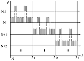
- FIG. 1 is a schematic timing diagram of one embodiment of a driving method of the present disclosure
- FIG. 2 is a schematic timing diagram of another embodiment of a driving method of the present disclosure.
- FIG. 3 is a schematic timing diagram of still another embodiment of a driving method of the present disclosure.
- FIG. 4 is a schematic timing diagram of still another embodiment of a driving method of the present disclosure.
- Figure 5 is a schematic timing diagram of one embodiment of a driving method of the present disclosure.
- FIG. 6 is a schematic timing diagram of another embodiment of a driving method of the present disclosure.
- Figure 7 is a schematic block diagram of a drive system in accordance with an embodiment of the present disclosure.
- FIG. 8 is a schematic block diagram of a driving system according to another embodiment of the present disclosure.
- Figure 9 is a schematic circuit diagram of a drive system in accordance with an embodiment of the present disclosure.
- FIG. 10, FIG. 11A and FIG. 11B are schematic flowcharts showing the working process of the driving system according to an embodiment of the present disclosure.
- the flow characteristics of the microfluid are not the same as those of the macroscopic fluid, so the microfluidic drive control method is different from the macroscopic fluid.
- surface tension drive has made effective progress.
- Dielectric wetting technology has become one of the research hotspots of microdroplet drive technology by highly controlling surface tension.
- the contact angle hysteresis is common in the droplet wetting system of the order of centimeters to micrometers.
- the contact angle lag is one of the important factors hindering the moving speed of the microdroplet, and gives micro Droplet drive brings additional errors.
- the embodiments of the present disclosure propose a driving method and a driving system capable of effectively improving the contact angle lag problem in the digital microfluidic chip and capable of improving the moving speed of the droplet.
- the driving method of the embodiment of the present disclosure is applied to a digital microfluidic chip.
- the digital microfluidic chip generally includes a substrate, an electrode array composed of a plurality of rows and columns of electrodes disposed on the substrate, a dielectric layer disposed on the substrate in a manner of covering the electrode array, and a hydrophobic layer overlying the dielectric layer.
- the droplet is initially placed on the hydrophobic layer at a position corresponding to one of the electrodes in the electrode array, and when it is required to move the droplet to a position corresponding to the next electrode on the hydrophobic layer, the lowering is performed for a certain driving period.
- An electrode continuously applies a drive signal of a certain frequency to pull the droplet to move to the position.
- the phenomenon of contact angle lag is likely to occur during the movement of the droplets, and the driving method of the embodiment of the present disclosure can well improve this phenomenon.
- timing waveforms in the respective drawings are merely illustrative and are not intended to limit the waveforms of the respective driving signals used in the actual implementation of the present disclosure.
- FIG. 1 is a schematic timing diagram of one embodiment of a driving method of the present disclosure.
- FIG. 1 shows a timing chart for applying driving signals to sequentially adjacent electrodes N-1, N, N+1, N+2 of the digital microfluidic chip.
- T1 the driving period during which the counter electrode N is driven
- the driving signal is applied to the electrode N but also the counter electrode N is applied.
- -1 applies a driving signal for a certain period of time, during which T1 corresponds to the first electrode of the present disclosure, and electrode N corresponds to the second electrode of the present disclosure.
- the electrode N+1 corresponds to the first electrode of the present disclosure
- the electrode N+1 corresponds to the second electrode of the present disclosure.
- the electrode N+2 is driven, that is, during the movement of the droplet on the chip from the position of the electrode N+1 to the position of the electrode N+2, not only the electrode N+2 is applied.
- the droplet is driven from the first electrode to the second electrode as an example, but the disclosure is not limited thereto, and the first electrode and the second electrode may be interchanged in practical applications, for example, from the electrode N toward When the electrode N+1 moves the droplet, the electrode N corresponds to the first electrode, and the electrode N+1 corresponds to the second electrode; when the droplet needs to be moved from the electrode N+1 to the electrode N in the subsequent step, the electrode N+1 corresponds to the An electrode, the electrode N corresponding to the second electrode.
- the period in which the driving signal is applied to the first electrode is shifted from the period in which the driving signal is applied to the second electrode, that is, At some point during a drive cycle, only one of the first electrode and the second electrode is applied with a drive signal.
- the driving signal applied to the first electrode corresponds to the first driving signal of the present disclosure
- the driving signal applied to the second electrode corresponds to the second driving signal of the present disclosure.
- the total duration of the application period of the first driving signal is smaller than the total duration of the application period of the second driving signal in each driving period T1, T2 or T3 or the like.
- the second electrode applies a pulling force to the droplet for a period of time
- the first electrode applies a pulling force to the liquid droplet for a short period of time
- the second electrode continues to apply the pulling force, so that the contact angle becomes small when the liquid droplet continues to move in the same direction, so that the liquid droplet moves in the opposite direction in a timely manner.
- the contact angle is adjusted, and then the droplets continue to move in the original direction. Therefore, by the driving scheme of the embodiment of the present disclosure, the contact angle during the traveling of the droplet in the digital microfluidic chip can be accurately controlled, the existing contact angle hysteresis is effectively improved, and the moving speed of the droplet is improved.
- the frequency of the first driving signal is substantially the same as the frequency of the second driving signal, but the disclosure is not limited thereto.
- the frequency of the first driving signal may also be smaller than the frequency of the second driving signal to facilitate the stability of the droplet shape.
- the frequency, the amplitude, the duty ratio, and the duration of the application period of the second driving signal may be the same or different from each other in each application period, and may be different according to the droplet.
- the required speed of movement, etc., is appropriately adjusted, and the present disclosure is not limited thereto.
- the application period of the first driving signal (such as the driving signal applied to N-1 during T1) may include two periods separated from each other by an interval period, but the present disclosure is not limited thereto.
- the different embodiments regarding the application period of the first drive signal will be specifically described below.
- FIG. 2 is a schematic timing diagram of another embodiment of a driving method of the present disclosure.
- the application period of the first driving signal in the present embodiment includes only one continuous period corresponding to the first period of the present disclosure.
- This first period is shown in FIG. 2 in the middle rear portion of the driving period T1/T2/T3, but the present disclosure is not limited thereto.
- the first time period may also be set at the beginning, the front middle portion, the middle portion or the rear portion of the driving period T1/T2/T3, and specifically, the position of the first time period may be determined according to the contact angle of the liquid droplets detected in real time. For example, during the movement of the droplet from the electrode N-1 to the electrode N, it is detected in real time that the contact angle of the droplet is not ideal, and the application of the driving voltage to the electrode N may be stopped, and the driving voltage may be applied to the electrode N-1 for a while. To adjust the contact angle of the droplets at any time to precisely control the contact angle of the droplets during the movement of the droplets.
- the present disclosure also includes other various embodiments (not shown), such as in one embodiment, in one embodiment, the middle of the period T1 applies a first driving signal to the electrode N-1, the middle rear portion during T2 applies a first driving signal to the electrode N, and the middle and rear portions during T3 applies a first driving signal to the electrode N+1;
- the first driving signal is applied to the front of the electrode N-1 during the period T1, the first driving signal is applied to the electrode N during the middle period of T2, and the first electrode is applied to the electrode N+1 during the middle period of T3.
- a drive signal, and so on is applied to the front of the electrode N-1 during the period T1
- the first driving signal is applied to the electrode N during the middle period of T2
- the first electrode is applied to the electrode N+1 during the middle period of T3.
- FIG. 3 is a schematic timing diagram of still another embodiment of the driving method of the present disclosure.
- the application period of the first driving signal in each driving period T1/T2/T3 in the present embodiment includes three periods separated from each other by an interval period corresponding to the present disclosure.
- the adjacent second time periods may have an interval of the same duration.
- the duration of each second period may be the same, and the duration of the second period may be proportional to the duration of the interval period.
- Embodiments of the present disclosure are capable of applying a relatively stable force to the droplets through the electrodes, facilitating maintaining the state of the droplets.
- FIG. 4 is a schematic timing diagram of still another embodiment of a driving method of the present disclosure.
- the application period of the first driving signal in each driving period T1/T2/T3 includes three periods separated by interval periods of different durations, which correspond to the present period.
- the second time period of disclosure the durations of the second time periods in the same driving period may be different from each other.
- the interval period between the second periods in the same driving period may also be proportional to the duration of the second period, for example, in the three second periods during which the driving signal is applied to the electrode N-1 during the driving period T1 in FIG.
- the interval period between the second periods in which the duration is short is smaller than the interval period between the second periods in which the duration is longer.
- the application period of the first driving signal during each driving period T1/T2/T3 may further include three or more periods of different intervals. A second period of time that is separated from each other by the same duration.
- FIG. 5 is a schematic timing diagram of one embodiment of a driving method of the present disclosure.
- the manners of setting the second period in which the first driving signal is applied in the driving periods T1, T2, and T3 in the present embodiment may be different from each other.
- the driving period T1 the setting mode of the embodiment shown in FIG. 2 can be adopted.
- the driving period T2 the setting mode of the embodiment shown in FIG. 3 can be adopted, and in the driving period T3, the embodiment shown in FIG. 4 can be used. Setting method.
- the manner in which the second period in which the first driving signal is applied in each driving period in the present disclosure is not limited to the setting manner shown in FIG. 5, for example, the partial driving periods in all the driving periods may have the same setting manner.
- FIG. 6 is a schematic timing diagram of another embodiment of a driving method of the present disclosure.
- a period in which the first driving signal is applied to the first electrode is set in the middle of the driving period, for example, in a driving period of time T.
- T1 the period from 2T/5 to 3T/5.
- Embodiments of the present disclosure have a better effect on the degree of control over the droplet contact angle.
- the period in which the first driving signal is applied to the first electrode in the present disclosure is not limited to the value shown in FIG. 6.
- the period in which the first driving signal is applied to the first electrode may be a period from 9T/20 to 11T/20 in the driving period T1.
- the application period in which the first driving signal is applied to the first electrode in the driving period T1 includes a plurality of periods, for example, including two periods
- the two periods may be, for example, from 1T/5 to 2T in the driving period T1, respectively.
- /5 period as well as period from 3T/5 to 4T/5.
- the ratio between the total duration of the application period of the first driving signal and the duration of the driving period may be in the range of 0.1-0.4.
- various parameters of the first drive signal may be adjusted in real time.
- the contact angle of the liquid droplet may be detected in real time at the beginning of a certain application period of the first driving signal, and the frequency of the first driving signal in the application period may be adjusted according to the measured contact angle, for example, the frequency may be It is set such that the smaller the contact angle is, the lower the frequency.
- the frequency of the first driving signal is adjusted according to the magnitude of the contact angle detected in real time, and the control precision of the droplet can be improved.
- the duty ratio of the first driving signal in the application period may be set according to the contact angle of the droplet detected at the beginning of the application period of the first driving signal to be occupied when the measured contact angle is smaller. The smaller the ratio.
- This embodiment can also improve the control precision of the liquid droplets.
- the duration of the application period of the first driving signal may be set to be longer as the measured contact angle is smaller according to the contact angle of the droplet detected at the beginning of the application period of the first driving signal.
- This embodiment can also improve the control precision of the droplets.
- the contact angle of the liquid droplets in real time at the end of a certain application period of the first driving signal, and set the application period and the next application period of the first driving signal according to the measured magnitude of the contact angle.
- the duration of the interval period between, for example, the length of the interval period between the application period and the next application period may be set to be shorter as the measured contact angle is smaller. This embodiment can also improve the control precision of the liquid droplets.
- the fundamental frequency of the first driving signal and/or the second driving signal and the duration of the application period may be determined according to the dielectric layer thickness of the digital microfluidic chip.
- the first driving signal and/or the second driving signal may be set such that the thicker the dielectric layer is, the lower the set frequency or the longer the duration of the application period.
- the drive period may also need to be appropriately increased.
- Embodiments of the present disclosure are capable of adapting to the characteristics of different digital microfluidic chips, effectively controlling the contact angle of the droplets.
- Figure 7 is a schematic block diagram of a drive system in accordance with one embodiment of the present disclosure.
- the driving system of the embodiment of the present disclosure is applied to the aforementioned digital microfluidic chip, and the digital microfluidic chip includes an electrode array composed of a plurality of rows and columns of electrodes, and the driving system of the embodiment of the present disclosure is used for each pair of adjacent The droplets are driven between the electrodes, the pair of adjacent electrodes corresponding to the first electrode and the second electrode in the present disclosure.
- the driving system of the embodiment of the present disclosure includes a driving signal generating device 1 and a controller 2 for driving control of the digital microfluidic chip 3.
- the drive signal generating device 1 may be configured to generate a first drive signal for the first electrode and a second drive signal for the second electrode.
- the drive signal generating device 1 can be, for example, a square wave generator, a sawtooth wave generator, or the like.
- the controller 2 may be configured to control to apply the first drive signal to the first electrode and the second drive signal to the second electrode during a drive period of the second electrode.
- the controller 2 may be configured to shift the application period of the first driving signal and the application period of the second driving signal from each other, and the controller 2 may be configured to be in the driving period of the second electrode.
- the total duration of the application period of the first drive signal is made smaller than the total duration of the application period of the second drive signal.
- the controller 2 can control according to a preset period of time when controlling the application period of the first driving signal.
- FIG. 8 is a schematic block diagram of a drive system according to another embodiment of the present disclosure.
- the driving system of the embodiment of the present disclosure may further include a contact angle detecting device 4 that may be configured to detect a contact angle of the liquid droplets, and the controller 2 may be configured to be based on the contact angle of the liquid droplets measured in real time. Control or adjust various parameters of the first drive signal.
- the controller 2 may be configured to determine the duration of the application period of the first driving signal, the duration of the application period, based on the contact angle measured by the contact angle detecting device 4 in real time at the beginning of an application period of the first driving signal The duty cycle of a drive signal and/or the frequency of the first drive signal during the application period.
- controller 2 may be further configured to determine the application period of the first driving signal and the first driving signal according to the contact angle measured by the contact angle detecting device 4 in real time at the end of one application period of the first driving signal. The length of the interval between application periods.
- Figure 9 is a schematic circuit diagram of a drive system in accordance with one embodiment of the present disclosure.
- the drive system of the embodiment of the present disclosure includes a drive signal generating device 10, a controller 20, a decoder 40, first and second photocouplers 51 and 52.
- the first and second photocouplers 51 and 52 correspond to the first and second switching devices of the present disclosure.
- the first photocoupler switch 51 is connected in a loop between the first electrode 61 and the drive signal generating device 10
- the second optocoupler switch 52 is connected in a loop between the second electrode 62 and the drive signal generating device 10.
- the controller 20 may be configured to turn on the first photocoupler switch 51 and turn off the second optocoupler switch 52 during an application period of the first driving signal, and to turn the first light during an application period of the second driving signal
- the coupling switch 51 is turned off and the second photocoupler switch 52 is turned on.
- a decoder 40 may be disposed between the controller 20 and the optocoupler switch, and the controller 20 transmits a control signal corresponding to the electrode to which the drive signal needs to be applied to the decoder 40, The encoder 40 accurately transmits the control signal to the photocoupler switch corresponding to the electrode.
- the first switching device and the second switching device are implemented by using an optocoupler switch, but the disclosure is not limited thereto.
- the first switching device and the second switching device may also be implemented by using other forms of semiconductor switches, such as direct A field effect transistor is used to implement the switching device.
- the application period of each drive signal can be controlled by setting a timer.
- a first timer may be set for timing the driving period T1, T2 or T3; and a second timer is set for performing the application period of the second driving signal. Timing; and setting a third timer for timing the application period of the first driving signal.
- FIG. 10, FIG. 11A and FIG. 11B are schematic flowcharts showing the working process of the driving system according to an embodiment of the present disclosure.
- the controller 20 is initialized by, for example, communicating with the controller 20 by a computer (PC), and the moving speed and moving path data of the liquid droplets are read from the PC side, and the moving speed of the liquid droplets is set and Move the path.
- the first timer is set according to the set droplet moving speed for setting a driving period (such as T1/T2/T3) for applying a driving voltage to one electrode, and setting the second timer and the third timer.
- the position of the drop is read to determine whether the set moving path is satisfied. If it is not satisfied, it is fed back to the PC end to invite the replay of the drop. If the set moving path is satisfied, the controller 20 sends an instruction to the decoder 40 to turn on the optocoupler switch corresponding to the next electrode of the electrode where the drop is located, and simultaneously turn on the first timer and the second timer.
- the PWM control signal is transmitted to the drive signal generating device 10 to generate a drive signal of a specific frequency, for example, a drive square wave.
- the second timer interrupt is entered, as shown in FIG. 11A, the droplet position is read at the timing interrupt, and the detection is performed. And determine the droplet contact angle lag condition, set the drive signal frequency according to the tailing situation (for example, drive the square wave frequency), and also set the duty ratio of the drive signal to end the interruption. Then, the third timer is turned on, and the first driving signal is output to the first electrode according to the frequency of the driving signal set during the second timer interruption, and waits for the third timer to overflow.
- the drive signal frequency for example, drive the square wave frequency
- the third timer interrupt When the third timer overflows (ie, when one application period of applying the first driving signal to the first electrode ends), the third timer interrupt is entered, and as shown in FIG. 11B, the second for the second electrode may be reset.
- the frequency and duty cycle of the drive signal eg, driving a square wave.
- the driving square wave of the driving frequency reset during the third timer interrupt is output to the second electrode, and then waits for the first timer to overflow.
- the first timer overflows ie, one drive cycle ends)
- the first timer interrupt is entered, the drop position is read, and it is determined whether the drop moves on the set moving path, if the movement is on the set moving path. Then, the above steps are repeated for the next electrode, and if the droplet position is shifted, the droplet is pulled back to the set moving path according to the above-described driving method.
- the driving scheme of the embodiment of the present disclosure can accurately control the contact angle during the droplet traveling in the digital microfluidic chip, effectively improve the existing contact angle hysteresis, and improve the moving speed of the droplet.
Landscapes
- Chemical & Material Sciences (AREA)
- Health & Medical Sciences (AREA)
- Dispersion Chemistry (AREA)
- Analytical Chemistry (AREA)
- General Health & Medical Sciences (AREA)
- Hematology (AREA)
- Clinical Laboratory Science (AREA)
- Chemical Kinetics & Catalysis (AREA)
- Physical Or Chemical Processes And Apparatus (AREA)
- Micromachines (AREA)
Priority Applications (3)
| Application Number | Priority Date | Filing Date | Title |
|---|---|---|---|
| JP2019569427A JP7280199B2 (ja) | 2017-09-29 | 2018-07-09 | デジタルマイクロ流体チップ用の駆動方法及び駆動システム |
| EP18861776.5A EP3689463A4 (en) | 2017-09-29 | 2018-07-09 | CONTROL PROCESS AND DRIVER SYSTEM FOR USE IN A DIGITAL MICROFLUIDIC CHIP |
| US16/338,811 US11446656B2 (en) | 2017-09-29 | 2018-07-09 | Driving method and driving system for digital microfluidic chip |
Applications Claiming Priority (2)
| Application Number | Priority Date | Filing Date | Title |
|---|---|---|---|
| CN201710910461.6A CN107617451B (zh) | 2017-09-29 | 2017-09-29 | 一种微流控芯片的驱动方法和驱动系统 |
| CN201710910461.6 | 2017-09-29 |
Publications (1)
| Publication Number | Publication Date |
|---|---|
| WO2019062267A1 true WO2019062267A1 (zh) | 2019-04-04 |
Family
ID=61091103
Family Applications (1)
| Application Number | Title | Priority Date | Filing Date |
|---|---|---|---|
| PCT/CN2018/094943 Ceased WO2019062267A1 (zh) | 2017-09-29 | 2018-07-09 | 用于数字微流控芯片的驱动方法和驱动系统 |
Country Status (5)
| Country | Link |
|---|---|
| US (1) | US11446656B2 (enExample) |
| EP (1) | EP3689463A4 (enExample) |
| JP (1) | JP7280199B2 (enExample) |
| CN (1) | CN107617451B (enExample) |
| WO (1) | WO2019062267A1 (enExample) |
Cited By (1)
| Publication number | Priority date | Publication date | Assignee | Title |
|---|---|---|---|---|
| CN113805035A (zh) * | 2020-06-17 | 2021-12-17 | 佛山奥素博新科技有限公司 | 一种数字微流控系统的检测电路和检测方法 |
Families Citing this family (7)
| Publication number | Priority date | Publication date | Assignee | Title |
|---|---|---|---|---|
| CN107617451B (zh) * | 2017-09-29 | 2019-06-04 | 京东方科技集团股份有限公司 | 一种微流控芯片的驱动方法和驱动系统 |
| CN108654711B (zh) * | 2018-06-07 | 2020-03-31 | 西南科技大学 | 一种降低电场下固液界面粘-滑行为的方法 |
| CN109126917B (zh) * | 2018-10-09 | 2020-04-10 | 京东方科技集团股份有限公司 | 微流控芯片及其驱动方法 |
| CN109622085B (zh) | 2019-01-31 | 2021-12-24 | 京东方科技集团股份有限公司 | 微流控芯片的驱动方法及其装置、微流控系统 |
| CN110010086B (zh) | 2019-03-29 | 2020-12-22 | 上海中航光电子有限公司 | 电润湿面板的驱动方法 |
| CN112415357B (zh) * | 2019-08-21 | 2025-09-16 | 佛山奥素博新科技有限公司 | 数字微流控设备与dmf驱动系统连接的检测方法、系统 |
| CN120576153B (zh) * | 2024-11-14 | 2025-11-14 | 康沃思(天津)生物科技有限公司 | 基于声束流实现微水锤效应的方法及装置 |
Citations (7)
| Publication number | Priority date | Publication date | Assignee | Title |
|---|---|---|---|---|
| CN102175744A (zh) * | 2011-01-06 | 2011-09-07 | 复旦大学 | 一种数字微流控技术的电化学传感器芯片 |
| CN102600919A (zh) * | 2012-03-20 | 2012-07-25 | 复旦大学 | 一种限制数字微流控芯片液滴单向输运的方法 |
| CN102824933A (zh) * | 2012-09-20 | 2012-12-19 | 复旦大学 | 一种单向液滴输运的数字微流芯片电极配置 |
| CN102879453A (zh) * | 2012-09-04 | 2013-01-16 | 吴传勇 | 基于电泳来操控液体中的带电粒子的方法及器件 |
| CN103865789A (zh) * | 2012-12-17 | 2014-06-18 | 台湾积体电路制造股份有限公司 | 集成生物实体操作和处理半导体器件的系统及方法 |
| US9254485B2 (en) * | 2012-12-17 | 2016-02-09 | Taiwan Semiconductor Manufacturing Company, Ltd. | Systems and methods for an integrated bio-entity manipulation and processing device |
| CN107617451A (zh) * | 2017-09-29 | 2018-01-23 | 京东方科技集团股份有限公司 | 一种微流控芯片的驱动方法和驱动系统 |
Family Cites Families (8)
| Publication number | Priority date | Publication date | Assignee | Title |
|---|---|---|---|---|
| JP3791999B2 (ja) | 1997-03-24 | 2006-06-28 | 株式会社アドバンス | 液体微粒子ハンドリング装置 |
| US8173000B1 (en) | 2011-01-18 | 2012-05-08 | Sharp Kabushiki Kaisha | Active matrix device and method of driving the same |
| US8828336B2 (en) * | 2011-02-02 | 2014-09-09 | Sharp Kabushiki Kaisha | Active matrix device |
| CN102350380B (zh) * | 2011-09-26 | 2014-04-02 | 复旦大学 | 一种透明单平面单极性数字微流体芯片及其控制方法 |
| CN104035796A (zh) * | 2014-06-13 | 2014-09-10 | 苏州大学 | 一种ewod芯片液滴驱动方法及系统 |
| US9808800B2 (en) * | 2015-04-10 | 2017-11-07 | Unversity Of Macau | Electrode-voltage waveform for droplet-velocity and chip-lifetime improvements of digital microfluidic systems |
| WO2017007757A1 (en) * | 2015-07-06 | 2017-01-12 | Illumina, Inc. | Balanced ac modulation for driving droplet operations electrodes |
| CN105233887B (zh) * | 2015-08-31 | 2017-06-23 | 中国科学院深圳先进技术研究院 | 一种基于介电润湿的微液滴驱动器件及其制备方法 |
-
2017
- 2017-09-29 CN CN201710910461.6A patent/CN107617451B/zh active Active
-
2018
- 2018-07-09 JP JP2019569427A patent/JP7280199B2/ja active Active
- 2018-07-09 WO PCT/CN2018/094943 patent/WO2019062267A1/zh not_active Ceased
- 2018-07-09 EP EP18861776.5A patent/EP3689463A4/en active Pending
- 2018-07-09 US US16/338,811 patent/US11446656B2/en active Active
Patent Citations (7)
| Publication number | Priority date | Publication date | Assignee | Title |
|---|---|---|---|---|
| CN102175744A (zh) * | 2011-01-06 | 2011-09-07 | 复旦大学 | 一种数字微流控技术的电化学传感器芯片 |
| CN102600919A (zh) * | 2012-03-20 | 2012-07-25 | 复旦大学 | 一种限制数字微流控芯片液滴单向输运的方法 |
| CN102879453A (zh) * | 2012-09-04 | 2013-01-16 | 吴传勇 | 基于电泳来操控液体中的带电粒子的方法及器件 |
| CN102824933A (zh) * | 2012-09-20 | 2012-12-19 | 复旦大学 | 一种单向液滴输运的数字微流芯片电极配置 |
| CN103865789A (zh) * | 2012-12-17 | 2014-06-18 | 台湾积体电路制造股份有限公司 | 集成生物实体操作和处理半导体器件的系统及方法 |
| US9254485B2 (en) * | 2012-12-17 | 2016-02-09 | Taiwan Semiconductor Manufacturing Company, Ltd. | Systems and methods for an integrated bio-entity manipulation and processing device |
| CN107617451A (zh) * | 2017-09-29 | 2018-01-23 | 京东方科技集团股份有限公司 | 一种微流控芯片的驱动方法和驱动系统 |
Non-Patent Citations (1)
| Title |
|---|
| See also references of EP3689463A4 |
Cited By (1)
| Publication number | Priority date | Publication date | Assignee | Title |
|---|---|---|---|---|
| CN113805035A (zh) * | 2020-06-17 | 2021-12-17 | 佛山奥素博新科技有限公司 | 一种数字微流控系统的检测电路和检测方法 |
Also Published As
| Publication number | Publication date |
|---|---|
| US20210362148A1 (en) | 2021-11-25 |
| CN107617451B (zh) | 2019-06-04 |
| EP3689463A1 (en) | 2020-08-05 |
| US11446656B2 (en) | 2022-09-20 |
| CN107617451A (zh) | 2018-01-23 |
| EP3689463A4 (en) | 2021-11-24 |
| JP2020534991A (ja) | 2020-12-03 |
| JP7280199B2 (ja) | 2023-05-23 |
Similar Documents
| Publication | Publication Date | Title |
|---|---|---|
| WO2019062267A1 (zh) | 用于数字微流控芯片的驱动方法和驱动系统 | |
| Kong et al. | Motorized actuation system to perform droplet operations on printed plastic sheets | |
| US20190366333A1 (en) | Electro-wetting-based microfluidic droplet positioning system and method | |
| CN109894169B (zh) | 电润湿面板及其工作方法 | |
| CN109894167B (zh) | 微流控芯片 | |
| CN111678423A (zh) | 基于介电润湿数字微流控的液滴检测系统及检测方法 | |
| CN212158459U (zh) | 基于介电润湿数字微流控的液滴检测系统 | |
| CN1511194A (zh) | 扩增多核苷酸的仪器和方法 | |
| CN112892625B (zh) | 一种微流控芯片 | |
| Zhou et al. | Electrostatic charging and control of droplets in microfluidic devices | |
| CN108405004A (zh) | 一种液滴生成控制方法及其系统 | |
| CN110694702B (zh) | 一种微流控芯片及驱动方法、微流控装置 | |
| CN102896007A (zh) | 一种微流控器件及其制备方法 | |
| CN110420673B (zh) | 一种微流控器件及其驱动方法、微流控系统 | |
| CN208407027U (zh) | 一种液滴生成控制系统 | |
| JP2022058180A (ja) | 誘電湿潤装置及び液滴検出方法 | |
| CN208302807U (zh) | 一种微流控芯片及其控制系统 | |
| CN208494260U (zh) | 基于介电泳的表面微液滴配发结构 | |
| CN106093382A (zh) | 一种梳齿式微流体延时器 | |
| CN210357208U (zh) | 一种便携式可拼接数字微流控驱动电路、装置及系统 | |
| CN109806803A (zh) | 一种具有电润湿阈门的微流体混合装置及其控制方法 | |
| Wu et al. | Fabrication of AD/DA microfluidic converter using deep reactive ion etching of silicon and low temperature wafer bonding | |
| CN223295747U (zh) | 一种声场和电场调控的生化液滴样本制备装置 | |
| CN207655159U (zh) | 一种基于电频率控制的微液滴驱动装置 | |
| CN101670998B (zh) | 点面电极系统及利用该系统进行微流体驱动的方法 |
Legal Events
| Date | Code | Title | Description |
|---|---|---|---|
| 121 | Ep: the epo has been informed by wipo that ep was designated in this application |
Ref document number: 18861776 Country of ref document: EP Kind code of ref document: A1 |
|
| ENP | Entry into the national phase |
Ref document number: 2019569427 Country of ref document: JP Kind code of ref document: A |
|
| NENP | Non-entry into the national phase |
Ref country code: DE |
|
| ENP | Entry into the national phase |
Ref document number: 2018861776 Country of ref document: EP Effective date: 20200429 |