WO2019062128A1 - 受流器的控制方法、装置和系统 - Google Patents
受流器的控制方法、装置和系统 Download PDFInfo
- Publication number
- WO2019062128A1 WO2019062128A1 PCT/CN2018/086143 CN2018086143W WO2019062128A1 WO 2019062128 A1 WO2019062128 A1 WO 2019062128A1 CN 2018086143 W CN2018086143 W CN 2018086143W WO 2019062128 A1 WO2019062128 A1 WO 2019062128A1
- Authority
- WO
- WIPO (PCT)
- Prior art keywords
- current
- receiver
- control command
- receiving device
- rail
- Prior art date
- Legal status (The legal status is an assumption and is not a legal conclusion. Google has not performed a legal analysis and makes no representation as to the accuracy of the status listed.)
- Ceased
Links
Images




Classifications
-
- B—PERFORMING OPERATIONS; TRANSPORTING
- B60—VEHICLES IN GENERAL
- B60L—PROPULSION OF ELECTRICALLY-PROPELLED VEHICLES; SUPPLYING ELECTRIC POWER FOR AUXILIARY EQUIPMENT OF ELECTRICALLY-PROPELLED VEHICLES; ELECTRODYNAMIC BRAKE SYSTEMS FOR VEHICLES IN GENERAL; MAGNETIC SUSPENSION OR LEVITATION FOR VEHICLES; MONITORING OPERATING VARIABLES OF ELECTRICALLY-PROPELLED VEHICLES; ELECTRIC SAFETY DEVICES FOR ELECTRICALLY-PROPELLED VEHICLES
- B60L5/00—Current collectors for power supply lines of electrically-propelled vehicles
- B60L5/38—Current collectors for power supply lines of electrically-propelled vehicles for collecting current from conductor rails
- B60L5/39—Current collectors for power supply lines of electrically-propelled vehicles for collecting current from conductor rails from third rail
Definitions
- the present invention relates to the field of rail trains, and in particular to a method, device and system for controlling a flow receiver.
- the current receiver refers to a dynamic flow receiving device installed on the bogie of the rail vehicle to dynamically take the rail vehicle from the rigid power supply rail (ie, the third rail) to meet the power demand of the train.
- the current receiving device on the existing rail vehicle is fixed in structure due to the structure of the shoe arm (collector shoe and the receiving arm), and the power collecting shoe cannot be lifted and lowered.
- the shoe arm collector shoe and the receiving arm
- the current receiving device is easily received.
- the arm breaks and even damages the entire flow receiver and the bogie mounted there, reducing the life of the flow receiver.
- the operator can only stand the mechanical control lever to disengage the current supply device from the power supply rail one by one to identify the faulty current receiver. Not only cannot the faulty current collector be quickly determined, but also the operation is inconvenient and there is a safety hazard.
- Embodiments of the present invention provide a method, device, and system for controlling a current receiver to at least solve the problem that the existing rail vehicle has large wear and service life due to the structure of the collector shoe and the receiving arm of the current receiver. Reduced technical issues.
- a method of controlling a current receiver includes: receiving a control instruction for at least one current receiver on a rail vehicle, wherein the control command includes at least one of: for controlling The first control command in contact with the power supply rail, the second control command for controlling the disconnection of the current receiver from the power supply rail, and the control receiver to perform the lifting action and/or the lowering action according to the control command.
- a control system for a flow receiver comprising: at least one current receiver disposed on at least one of the rail vehicles; and an input device configured to receive on the rail vehicle a control command of the at least one current receiving device, wherein the control command comprises at least one of: a first control command for controlling contact of the current receiving device with the power supply rail, and a second control command for controlling the disconnection of the current receiving device from the power supply rail And a control device configured to control the flow receiver to perform a lifting action and/or a lowering action according to the control command.
- a control device for a current receiving device comprising: a receiving unit configured to receive a control command for at least one current receiving device on a rail vehicle, wherein the control command comprises at least the following One: a first control command for controlling contact of the current receiving device with the power supply rail, a second control command for controlling the disconnection of the current receiving device from the power supply rail; and a control unit configured to control the flow converter to perform the rising according to the control command Boot action and/or lower boots action.
- a storage medium comprising a stored program, wherein the program executes the above-described control method of the current collector.
- a processor for executing a program, wherein the program is controlled to execute the above-described control method of the current collector.
- control command for at least one current receiver on the rail vehicle
- the control command comprises at least one of: a first control command for controlling contact of the current receiver with the power rail, Controlling the second control command of the flow receiver and the power supply rail; controlling the flow receiving device to perform the lifting action and/or the lowering action according to the control instruction, so as to control the flow only when the current receiving device is required to be flown
- FIG. 1 is a flow chart of a control method of a current receiver according to an embodiment of the present invention
- FIG. 2 is a schematic diagram of an alternative train grouped by four vehicles, in accordance with an embodiment of the present invention
- FIG. 3 is a flow chart of an alternative method of controlling a current receiver according to an embodiment of the present invention.
- FIG. 4 is a flow chart of an alternative method of controlling a current receiver according to an embodiment of the present invention.
- FIG. 5 is a flow chart of an alternative method of controlling a current receiver according to an embodiment of the present invention.
- FIG. 6 is a flow chart of an alternative method of controlling a current receiver according to an embodiment of the present invention.
- FIG. 7 is a schematic diagram of a control system of a current receiver according to an embodiment of the present invention.
- FIG. 8 is a schematic diagram of an optional control system of a current receiver according to an embodiment of the present invention.
- FIG. 9 is a schematic diagram of an optional current receiving circuit control circuit according to an embodiment of the present invention.
- FIG. 10 is a schematic diagram of an optional current-carrying device overcurrent detecting circuit according to an embodiment of the invention.
- FIG. 11 is a schematic diagram of an optional receiver riser in-position detection circuit according to an embodiment of the invention.
- FIG. 12 is a schematic diagram of an optional receiver remote control interface according to an embodiment of the present invention.
- Figure 13 is a schematic diagram of a control device for a flow acceptor in accordance with an embodiment of the present invention.
- an embodiment of a method of controlling a current receiver there is provided an embodiment of a method of controlling a current receiver, and it is to be noted that the steps illustrated in the flowchart of the accompanying drawings may be executed in a computer system such as a set of computer executable instructions, and Although the logical order is shown in the flowcharts, in some cases the steps shown or described may be performed in a different order than the ones described herein.
- FIG. 1 is a flow chart of a control method of a current receiver according to an embodiment of the present invention. As shown in FIG. 1, the method includes the following steps:
- Step S102 Receive a control instruction for at least one current receiver on the rail vehicle, where the control command includes at least one of: a first control instruction for controlling contact of the current receiver with the power rail, and a control receiver and The second control command for the power rail to detach.
- the above-mentioned rail vehicle may be a vehicle that dynamically withdraws from a power supply rail (third rail) through a current receiving device, including but not limited to a subway, a tram, a high-speed rail, a moving train, a train, and the like;
- the above-mentioned current-receiving device refers to a power receiving device that connects the rail vehicle and the power supply rail, and is generally disposed under the doors on both sides of the rail vehicle; the power supply rail refers to being installed beside the line (including but not limited to subway, light rail, etc.).
- a track that is individually set to supply power also known as the "third track.”
- the above control instructions may include, but are not limited to: a first control command for controlling contact of the current receiver with the power rail, and a second control command for controlling the disconnection of the current receiver from the power rail. It is easy to note that the rail vehicle can be dynamically taken from the supply rail by the receiver only if the receiver is in contact with the supply rail.
- the collector shoe and the flow receiving arm of the current rail vehicle are fixed structures, the collector shoe cannot be lifted and lowered, and always contacts the power supply rail, which causes the current collector to wear more.
- a current receiving device capable of controlling the lifting and lowering of the electric shoe is adopted, and when the current receiving device is required to be flown, the power collecting shoe is raised to make the current receiving device and the power supply.
- the rail contact can dynamically take the flow from the power supply rail; when the receiver is not required to be flowed, the collector shoe is lowered to disengage the flow receiver from the power supply rail, thereby reducing the wear on the flow receiver to improve the flow receiver The service life.
- Step S104 according to the control command, the flow receiver is controlled to perform a lifting action and/or a lowering action.
- the above-mentioned lifting action may refer to an action of controlling the lifting of the collector of the current receiving device.
- the collecting shoe When the collecting shoe is raised, the receiving device is in contact with the power supply rail, and the rail vehicle may The flow is dynamically taken from the power supply rail by the flow receiving device;
- the above-mentioned falling shoe action may refer to an action of controlling the falling of the collector shoe of the flow receiving device, and when the power collecting shoe is lowered, the current receiving device is separated from the power supply rail.
- step S104 when any one of the flow receivers on the rail vehicle receives the first control command for controlling the contact of the flow receiver with the power supply rail, the control receiver performs the lift operation; when on the rail vehicle In the case where any one of the current receiving devices receives the second control command for controlling the detachment of the flow receiving device from the power supply rail, the control receiver performs the lowering action.
- the control command may include at least the following information: the number information of the receiver, and the information of the car where the receiver is located. Wherein, according to the number information of the current receiver included in the first control command and the car information of the current receiver, any one of the receivers on any one of the rail vehicles can be controlled to perform the lifting action; according to the second control instruction The number information of the receiver included in the receiver and the information of the cabin where the receiver is located can control any one of the receivers on any one of the rail vehicles to perform the descending action.
- FIG. 2 is an alternative schematic diagram of trains grouped by four vehicles according to an embodiment of the present invention, as shown in FIG. 2, both ends of the head vehicle TC (trailer)
- Two sets of flow receivers (CCD1 and CCD2) are respectively arranged on two sides of one bogie, and four sets of current receivers (CCD1, CCD2, CCD3 and CCD4 are respectively arranged on both sides of the two bogies of the middle M1 ⁇ M2 (moving car).
- the car information and the number information of the current receiver to be raised or lowered may be added to the control command, thereby controlling the flow device to perform the rise. Boots or boots.
- the current collecting device that can be lifted and lowered by the collector shoe can receive the first control of the current receiving device when the rail vehicle needs to control the flow of any one of the current receiving devices.
- the purpose of contact with the power supply rail is to achieve the technical effect of reducing the wear of the current collector and improving the service life of the flow receiver, thereby solving the problem that the existing railway vehicle is affected by the fixed structure of the current collector and the receiving arm of the current receiver. The technical problem of large wearer and reduced service life.
- step S104 controlling the flow receiver to perform the lifting action and/or the lowering action, may include the following steps:
- Step S302 in the case that the control command is the first control command, controlling the receiver to perform the lifting action until the current receiving device contacts the power supply rail;
- Step S304 in the case that the control command is the second control command, the flow receiver is controlled to perform the lowering action until the flow receiver is disengaged from the power supply rail.
- the current receiving device for any one of the current receiving devices on the rail vehicle, if the first control command is received, the current receiving device is controlled to perform the lifting action until the current receiving device is in full contact with the power supply rail,
- the current receiving device can be dynamically taken from the power supply rail to supply power to the rail vehicle; if the second control command is received, the current receiving device is controlled to perform the lowering action until the current receiving device and the power supply rail are sufficiently separated to reduce The receiver is worn.
- step S302 in order to determine whether the receiver is in the boot position, as an optional implementation manner, as shown in FIG. 4, in the above step S302, in the case that the control command is the first control command, the control is performed.
- the receiver performs the lifting action until the receiver is in contact with the power rail, which may include the following steps:
- Step S402 detecting a contact pressure between the current receiving device and the power supply rail
- Step S404 determining whether the contact pressure reaches a preset pressure threshold
- step S406 if the contact pressure does not reach the preset pressure threshold, the first fault prompt information is output, wherein the first fault prompt information is used to prompt that there is no successful contact between the current receiver and the power rail.
- the preset pressure threshold may be a pressure value indicating that the current receiving device is in sufficient contact with the power supply rail to enable the current receiving device to dynamically take off from the power supply rail, and the lifter is executed in the control flow receiver.
- the contact pressure between the current receiving device and the power supply rail can be detected, and according to the contact pressure, it is judged whether the current receiving device is in the position of the lifter, and in the case that the receiver lifter is not in place, the output is used for prompting the receiving There is no fault message for successful contact between the flow unit and the power rail.
- the outputting the first fault prompt information may include the following steps:
- Step S4061 re-controlling the contact of the current receiving device with the power supply rail
- the process of controlling the flow receiving device to perform the lifting action if it is detected that the contact pressure between the current receiving device and the power supply rail does not reach the preset pressure that the current receiving device is in full contact with the power supply rail, Threshold, it is possible to re-control the contact between the receiver and the power rail (ie, control the receiver to re-execute the lift), and only output the fault if the number of times the receiver and the power rail have not successfully contacted exceed the preset number of times. Prompt information can avoid the probability of false positives.
- the method may further include the following steps:
- Step S502 if the current receiver and the power supply rail are successfully separated, the first indication information is output;
- Step S504 if the current receiver and the power supply rail are successfully contacted, outputting the second indication information
- Step S506 if the contact between the current receiver and the power supply rail fails, the third indication information is output.
- the first indication information is output; and the process of controlling the current receiving device to perform the lifting action is performed. If the receiver is in successful contact with the power rail (ie, the contact pressure between the receiver and the power rail reaches a preset pressure threshold), the second indication message is output if there is no successful contact between the current regulator and the power rail (ie, the contact pressure between the current receiver and the power supply rail does not reach the preset pressure threshold), the third indication information is output, so that the current state of each receiver on the rail vehicle and the fault occurrence can be clearly seen. Streamer.
- the above three indications can be distinguished by the color displayed by the indicator light connected to each current receiver.
- the foregoing method may further include the following steps:
- Step S602 detecting status information of the receiver
- Step S604 determining, according to the state information, whether the current receiver is in an abnormal working state
- Step S606 in the case that the current receiver is in an abnormal working state, outputting second fault prompt information, wherein the second fault prompt information is used to characterize the receiver working abnormality.
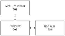
- FIG. 7 is a schematic diagram of a control system of the current receiver according to an embodiment of the present invention, as shown in FIG.
- the system includes: at least one current receiver 701, an input device 703, and a control device 705.
- An input device 703 configured to receive a control command for at least one current receiver on the rail vehicle, wherein the control command includes at least one of: a first control command for controlling contact of the current receiver with the power rail, for controlling a second control command that is disconnected from the power rail;
- the current collector that can be raised and lowered by the collector shoe is used, and when the rail vehicle needs to control the flow of any one of the receivers, the input device 703 receives the receiver. a first control command, and controlling, by the control device 705, the receiver to perform a lifting action according to the first control command to bring the current receiving device into contact with the power supply rail; and when the rail vehicle does not require the current receiving device to be flown, Receiving a second control command for the current receiving device through the input device 703, and controlling the current receiving device to perform a falling shoe action according to the second control command by the control device 705, so that the current receiving device is separated from the power supply rail, and the The purpose of controlling the contact between the current collector and the power supply rail is controlled only when the flow receiving device is required to be flowed, thereby realizing the technical effect of reducing the wear of the current collector and improving the service life of the flow receiver, thereby solving the existing rail vehicle. Due to the fixed structure of the current collector
- the receiver lift or lower boot control can have the following two forms: first, through the cab lift button SBCU, descending boots The button SBCD, the boot select switch SK and the like are manually controlled; secondly, the remote control of the network is performed through the setting button of the touch screen of the train network display.
- 9 is a schematic diagram of an optional current sink control circuit in accordance with an embodiment of the present invention.
- the descending boots button provided by the driver's cab can be used to control the lowering action of the receiver, when the train does not need to be from the third
- the descending shoe button is operated such that the collector of the current receiver is retracted (ie, the receiver performs the lowering action) to disengage from the third rail (ie, the power rail).
- the lift selector switch provided by the cab causes the train to raise only one side of the flow receiver, and the other side does not need to receive the flow receiver to be in the retracted state.
- a lift in place switch, a receiver fuse, and a network monitoring system may also be provided, so that the driver and the maintenance personnel monitor the state of the current receiver, whether the lift is in place, whether the flow device is overcurrent, or Short circuit, select the faulty current receiver through the network monitoring touch screen to quickly isolate the faulty current receiver.
- the receiver control system has a simple structure, convenient operation, practical and reliable.
- FIG. 12 is a schematic diagram of an optional remote control interface of the current receiver according to an embodiment of the present invention.
- the flow device such as M1 car CCD2 receiver
- the M1 car button press the M1 car button
- the CCD2 receiver button if the CCD2 receiver is isolated, press the red isolation button, corresponding The position of the CCD2 receiver is red. If it is put into the CCD2 receiver, press the green input button. When it is raised, the corresponding CCD2 receiver position will display green, and the receiver that has not touched the position will display black.
- control system of the current receiver comprises a lift button, a lower boots button, a lift solenoid valve, a lower shoe solenoid valve, a left and right boot switch, a lift shoe in place switch, and It consists of a fuse, a network monitoring system and a relay.
- the utility model has the advantages of simple control, convenient operation, practicality and reliability, reduces the danger of the operator, can realize the convenient and rapid judgment of the faulty current receiver, and can isolate the faulty flow device through the touch screen of the network system, and the system is safe, reliable and practical, and can Greatly improve the service life of the receiver.
- FIG. 13 is a schematic diagram of a control apparatus of the current receiver according to an embodiment of the present invention, as shown in FIG.
- the device includes: a receiving unit 131 and a control unit 133.
- the receiving unit 131 is configured to receive a control instruction for the at least one current receiving device on the rail vehicle, wherein the control command comprises at least one of: a first control instruction for controlling contact of the current receiving device with the power supply rail, a second control command for controlling the disconnection of the current receiving device from the power supply rail;
- the control unit 133 is configured to control the receiver to perform a lifting action and/or a lowering action according to the control command.
- the foregoing receiving unit 131 and the control unit 133 correspond to steps S102 to S104 in Embodiment 1, and the foregoing units are the same as the examples and application scenarios implemented by the corresponding steps, but are not limited to the foregoing Embodiment 1 Public content. It should be noted that the above described units may be implemented as part of a device in a computer system such as a set of computer executable instructions.
- the current collector that can be raised and lowered by the collector shoe is used, and when the rail vehicle needs to control the flow of any one of the receivers, the receiving unit 131 receives the receiver. a first control command, and controlling, by the control unit 133, the receiver to perform a lifting action according to the first control instruction to bring the current receiving device into contact with the power supply rail; and when the rail vehicle does not require the current receiving device to be flown, Receiving, by the receiving unit 131, the second control instruction for the current receiving device, and controlling, by the control unit 133, the falling device to perform the lowering action according to the second control instruction, so that the current receiving device is separated from the power supply rail, and the reaching
- the purpose of controlling the contact between the current collector and the power supply rail is controlled only when the flow receiving device is required to be flowed, thereby realizing the technical effect of reducing the wear of the current collector and improving the service life of the flow receiver, thereby solving the existing rail vehicle. Due to the fixed
- control command includes at least the following information: number information of the receiver, and car information of the receiver.
- control unit 133 includes: a first control module configured to control the receiver to perform a lifting action until the current receiving device and the power supply are provided when the control command is the first control command The rail contact; or the second control module is configured to control the receiver to perform the lowering action until the current regulator is disengaged from the power rail if the control command is the second control command.
- the first control module includes: a detecting module configured to detect a contact pressure between the current receiving device and the power supply rail; and a determining module configured to determine whether the contact pressure reaches a preset pressure threshold;
- the output module is configured to output a first fault prompt message if the contact pressure does not reach the preset pressure threshold, wherein the first fault prompt information is used to prompt that there is no successful contact between the current receiver and the power rail.
- the output module includes: a control submodule configured to re-control the receiver to be in contact with the power rail; and an output submodule configured to exceed the number of times the receiver and the power rail have not successfully contacted In the case of a preset number of times, the first failure prompt information is output.
- the apparatus further includes: a first display unit configured to output first indication information if the current receiver and the power supply rail are successfully detached; and a second display unit configured to be if the current receiver The second indication unit outputs a second indication information if the contact with the power supply rail is successfully contacted, and the third indication unit is configured to output the third indication information if the contact between the current supply unit and the power supply rail fails.
- the apparatus further includes: a detecting unit configured to detect state information of the current receiver; and a determining unit configured to determine whether the current receiving device is in an abnormal working state according to the state information; It is configured to output a second fault prompt message when the receiver is in an abnormal working state, wherein the second fault prompt information is used to characterize the receiver working abnormality.
- a storage medium comprising a stored program, wherein the program performs an optional or preferred method of controlling the current collector of any one of Embodiment 1.
- a processor configured to execute a program, wherein the program is controlled to execute the control method of the current receiver.
- the present invention controls the contact between the current receiving device and the power supply rail by controlling the raising or lowering of the power collecting shoe, on the one hand, reducing wear and improving the life, and further, by detecting the working state of each current receiving device, In the event of a failure of the receiver, the faulty receiver is quickly isolated.
- the disclosed technical contents may be implemented in other manners.
- the device embodiments described above are only schematic.
- the division of the unit may be a logical function division.
- there may be another division manner for example, multiple units or components may be combined or may be Integrate into another system, or some features can be ignored or not executed.
- the mutual coupling or direct coupling or communication connection shown or discussed may be an indirect coupling or communication connection through some interface, unit or module, and may be electrical or otherwise.
- the units described as separate components may or may not be physically separated, and the components displayed as units may or may not be physical units, that is, may be located in one place, or may be distributed to multiple units. Some or all of the units may be selected according to actual needs to achieve the purpose of the solution of the embodiment.
- each functional unit in each embodiment of the present invention may be integrated into one processing unit, or each unit may exist physically separately, or two or more units may be integrated into one unit.
- the above integrated unit can be implemented in the form of hardware or in the form of a software functional unit.
- the integrated unit if implemented in the form of a software functional unit and sold or used as a standalone product, may be stored in a computer readable storage medium.
- the technical solution of the present invention which is essential or contributes to the prior art, or all or part of the technical solution, may be embodied in the form of a software product stored in a storage medium.
- a number of instructions are included to cause a computer device (which may be a personal computer, server or network device, etc.) to perform all or part of the steps of the methods described in various embodiments of the present invention.
- the foregoing storage medium includes: a U disk, a Read-Only Memory (ROM), a Random Access Memory (RAM), a removable hard disk, a magnetic disk, or an optical disk, and the like. .
Landscapes
- Engineering & Computer Science (AREA)
- Power Engineering (AREA)
- Transportation (AREA)
- Mechanical Engineering (AREA)
- Current-Collector Devices For Electrically Propelled Vehicles (AREA)
- Train Traffic Observation, Control, And Security (AREA)
Abstract
本发明公开了一种受流器的控制方法、装置和系统。其中,该方法包括:接收对轨道车辆上至少一个受流器的控制指令,其中,控制指令包括如下至少之一:用于控制受流器与供电轨接触的第一控制指令、用于控制受流器与供电轨脱离的第二控制指令;根据控制指令,控制受流器执行升靴动作和/或降靴动作。本发明解决了现有的轨道车辆由于受流器的集电靴与受流臂结构固定导致受流器磨损大、使用寿命降低的技术问题。
Description
本发明涉及轨道列车领域,具体而言,涉及一种受流器的控制方法、装置和系统。
受流器,是指安装在轨道车辆的转向架上,为轨道车辆从刚性供电轨(即第三轨)进行动态取流,以满足列车电力需求的一套动态受流设备。
现有轨道车辆上的受流器由于靴臂(集电靴和受流臂)结构固定,不能升降集电靴,当滑靴在运行轨道上受到外力时,容易使的受流器的受流臂断裂,甚至损坏整个受流器和与之安装的转向架,使得受流器的使用寿命降低。另外,如果受流器由于过流或短路等原因发生故障,操作人员只能站在车门处通过机械操纵杆逐个使受流器与供电轨脱开,以判别故障受流器,这种方式,不仅无法迅速判断出发生故障的受流器,而且操作不便,存在安全隐患。当故障受流器脱离供电轨后,在路况不好或和速度高的情况下,容易损坏受流器或造成列车超出限界、绝缘距离降低、列车运行可靠性低;由于机械脱轨后不能线上恢复,致使受流器大多脱轨而导致轨道车辆不能正常运行。为了机械脱离供电轨,需要在受流支撑臂上增加回退装置部件,结构较复杂,不利于受流器小型轻量化。
针对上述现有的轨道车辆由于受流器的集电靴与受流臂结构固定导致受流器磨损大、使用寿命降低的问题,目前尚未提出有效的解决方案。
发明内容
本发明实施例提供了一种受流器的控制方法、装置和系统,以至少解决现有的轨道车辆由于受流器的集电靴与受流臂结构固定导致受流器磨损大、使用寿命降低的技术问题。
根据本发明实施例的一个方面,提供了一种受流器的控制方法,包括:接收对轨道车辆上至少一个受流器的控制指令,其中,控制指令包括如下至少之一:用于控制受流器与供电轨接触的第一控制指令、用于控制受流器与供电轨脱离的第二控制指令;根据控制指令,控制受流器执行升靴动作和/或降靴动作。
根据本发明实施例的另一方面,还提供了一种受流器的控制系统,包括:至少一个受流器,部署于轨道车辆的至少一个车厢上;输入设备,设置为接收对轨道车辆上至少一个受流器的控制指令,其中,控制指令包括如下至少之一:用于控制受流器与供电轨接触的第一控制指令、用于控制受流器与供电轨脱离的第二控制指令;控制装置,设置为根据控制指令,控制受流器执行升靴动作和/或降靴动作。
根据本发明实施例的另一方面,还提供了一种受流器的控制装置,包括:接收单元,设置为接收对轨道车辆上至少一个受流器的控制指令,其中,控制指令包括如下至少之一:用于控制受流器与供电轨接触的第一控制指令、用于控制受流器与供电轨脱离的第二控制指令;控制单元,设置为根据控制指令,控制受流器执行升靴动作和/或降靴动作。
根据本发明实施例的另一方面,还提供了一种存储介质,存储介质包括存储的程序,其中,程序执行上述的受流器的控制方法。
根据本发明实施例的另一方面,还提供了一种处理器,处理器用于运行程序,其中,程序运行时执行上述的受流器的控制方法。
在本发明实施例中,通过接收对轨道车辆上至少一个受流器的控制指令,其中,控制指令包括如下至少之一:用于控制受流器与供电轨接触的第一控制指令、用于控制受流器与供电轨脱离的第二控制指令;根据控制指令,控制受流器执行升靴动作和/或降靴动作,达到了只有在需要受流器受流的情况下才控制受流器与供电轨接触的目的,从而实现了降低受流器磨损、提高受流器使用寿命的技术效果,进而解决了现有的轨道车辆由于受流器的集电靴与受流臂结构固定导致受流器磨损大、使用寿命降低的技术问题。
此处所说明的附图用来提供对本发明的进一步理解,构成本申请的一部分,本发明的示意性实施例及其说明用于解释本发明,并不构成对本发明的不当限定。在附图中:
图1是根据本发明实施例的一种受流器的控制方法流程图;
图2是根据本发明实施例的一种可选的由四个车辆编组的列车示意图;
图3是根据本发明实施例的一种可选的受流器的控制方法流程图;
图4是根据本发明实施例的一种可选的受流器的控制方法流程图;
图5是根据本发明实施例的一种可选的受流器的控制方法流程图;
图6是根据本发明实施例的一种可选的受流器的控制方法流程图;
图7是根据本发明实施例的一种受流器的控制系统示意图;
图8是根据本发明实施例的一种可选的受流器的控制系统示意图;
图9是根据本发明实施例一种可选的受流器控制电路示意图;
图10是根据本发明实施例一种可选的受流器过流检测电路示意图;
图11是根据本发明实施例一种可选的受流器升靴到位检测电路示意图;
图12是根据本发明实施例一种可选的受流器远程控制界面示意图;以及
图13是根据本发明实施例的一种受流器的控制装置示意图。
为了使本技术领域的人员更好地理解本发明方案,下面将结合本发明实施例中的附图,对本发明实施例中的技术方案进行清楚、完整地描述,显然,所描述的实施例仅仅是本发明一部分的实施例,而不是全部的实施例。基于本发明中的实施例,本领域普通技术人员在没有做出创造性劳动前提下所获得的所有其他实施例,都应当属于本发明保护的范围。
需要说明的是,本发明的说明书和权利要求书及上述附图中的术语“第一”、“第二”等是用于区别类似的对象,而不必用于描述特定的顺序或先后次序。应该理解这样使用的数据在适当情况下可以互换,以便这里描述的本发明的实施例能够以除了在这里图示或描述的那些以外的顺序实施。此外,术语“包括”和“具有”以及他们的任何变形,意图在于覆盖不排他的包含,例如,包含了一系列步骤或单元的过程、方法、系统、产品或设备不必限于清楚地列出的那些步骤或单元,而是可包括没有清楚地列出的或对于这些过程、方法、产品或设备固有的其它步骤或单元。
实施例1
根据本发明实施例,提供了一种受流器的控制方法实施例,需要说明的是,在附图的流程图示出的步骤可以在诸如一组计算机可执行指令的计算机系统中执行,并且,虽然在流程图中示出了逻辑顺序,但是在某些情况下,可以以不同于此处的顺序执行所示出或描述的步骤。
图1是根据本发明实施例的一种受流器的控制方法流程图,如图1所示,该方法 包括如下步骤:
步骤S102,接收对轨道车辆上至少一个受流器的控制指令,其中,控制指令包括如下至少之一:用于控制受流器与供电轨接触的第一控制指令、用于控制受流器与供电轨脱离的第二控制指令。
作为一种可选的实施例,上述轨道车辆可以是通过受流器从供电轨(第三轨)进行动态取流的车辆,包括但不限于地铁、有轨电车、高铁、动车、火车等;上述受流器是指轨道车辆与供电轨进行连接的受电装置,通常设置于轨道车辆两侧车门下方;上述供电轨是指安装在轨道(包括但不限于地铁、轻轨等)线路旁边的,单独设置为供电的一条轨道,也称“第三轨”。上述控制指令可以包括但不限于:用于控制受流器与供电轨接触的第一控制指令、用于控制受流器与供电轨脱离的第二控制指令。容易注意的是,只有在受流器与供电轨接触的情况下,轨道车辆才可以通过受流器从供电轨进行动态取流。
需要说明的是,由于现有轨道车辆上的受流器的集电靴与受流臂采用的是固定结构,集电靴无法升降,始终与供电轨接触,会导致受流器磨损较大。作为一种可选的实施方案,本申请实施例中采用可以进行控制集电靴升降的受流器,在需要受流器受流的情况下,升起集电靴,使得受流器与供电轨接触,可以从供电轨动态取流;在不需要受理器受流的情况下,降下集电靴,使得受流器与供电轨脱离,从而降低对受流器的磨损,以提高受流器的使用寿命。
步骤S104,根据控制指令,控制受流器执行升靴动作和/或降靴动作。
作为一种可选的实施例,上述升靴动作可以是指控制受流器的集电靴升起的动作,当集电靴升起的情况下,受流器与供电轨接触,轨道车辆可以通过受流器从供电轨动态取流;上述降靴动作可以是指控制受流器的集电靴下降的动作,当集电靴下降的情况下,受流器与供电轨脱离。
在上述步骤S104中,当轨道车辆上的任意一个受流器接收到用于控制受流器与供电轨接触的第一控制指令的情况下,控制受流器执行升靴动作;当轨道车辆上的任意一个受流器接收到用于控制受流器与供电轨脱离的第二控制指令的情况下,控制受流器执行降靴动作。
一种可选的实施例中,上述控制指令中可以至少包括如下信息:受流器的编号信息、受流器所在的车厢信息。其中,根据第一控制指令中包含的受流器的编号信息和受流器所在的车厢信息,可以控制轨道车辆上任意一个车厢上的任意一个受流器执行升靴动作;根据第二控制指令中包含的受流器的编号信息和受流器所在的车厢信息, 可以控制轨道车辆上任意一个车厢上的任意一个受流器执行降靴动作。
假设上述轨道车辆由四个车厢编组的列车,图2是根据本发明实施例的一种可选的由四个车辆编组的列车示意图,如图2所示,两端头车TC(拖车)的一个转向架上两侧分别设置2套受流器(CCD1和CCD2),中间M1\M2(动车)的两个转向架上两侧分别设置4套受流器(CCD1、CCD2、CCD3和CCD4、)。当需要升起或降下某个(或某些)受流器时,可以将待升起或下降的受流器所在的车厢信息和编号信息添加到控制指令中,进而控制该受流器执行升靴或降靴动作。
由上可知,在本申请上述实施例中,采用集电靴可以升降的受流器,当轨道车辆需要控制任意一个受流器受流的情况下,通过接收对该受流器的第一控制指令,根据该第一控制指令控制受流器执行升靴动作,以使得受流器与供电轨接触;当轨道车辆不需要该受流器受流的情况下,通过接收对该受流器的第二控制指令,根据该第二控制指令控制该受流器执行降靴动作,以使得该受流器与供电轨脱离,达到了只有在需要受流器受流的情况下才控制受流器与供电轨接触的目的,从而实现了降低受流器磨损、提高受流器使用寿命的技术效果,进而解决了现有的轨道车辆由于受流器的集电靴与受流臂结构固定导致受流器磨损大、使用寿命降低的技术问题。
在一种可选的实施例中,如图3所示,上述步骤S104,根据控制指令,控制受流器执行升靴动作和/或降靴动作,可以包括如下步骤:
步骤S302,在控制指令为第一控制指令的情况下,控制受流器执行升靴动作,直到受流器与供电轨接触;或
步骤S304,在控制指令为第二控制指令的情况下,控制受流器执行降靴动作,直到受流器与供电轨脱离。
具体地,在上述实施例中,对于轨道车辆上的任意一个受流器,如果接收到第一控制指令,则控制受流器执行升靴动作,直到该受流器与供电轨充分接触,以使得该受流器可以从供电轨动态取流,进而为轨道车辆供电;如果接收到第二控制指令,则控制受流器执行降靴动作,直到该受流器与供电轨充分脱离,以降低该受流器的磨损。
进一步地,基于上述实施例,为了判断受流器是否升靴到位,作为一种可选的实施方式,如图4所示,上述步骤S302,在控制指令为第一控制指令的情况下,控制受流器执行升靴动作,直到受流器与供电轨接触,可以包括如下步骤:
步骤S402,检测受流器与供电轨之间的接触压力;
步骤S404,判断接触压力是否达到预设压力阈值;
步骤S406,在接触压力未达到预设压力阈值的情况下,输出第一故障提示信息,其中,第一故障提示信息用于提示受流器与供电轨之间没有成功接触。
具体地,在上述实施例中,上述预设压力阈值可以是表征受流器与供电轨充分接触以使得受流器可以从供电轨上动态取流的压力值,在控制受流器执行升靴动作的过程中,可以检测受流器与供电轨之间的接触压力,根据该接触压力判断受流器是否升靴到位,并在受流器升靴不到位的情况下,输出用于提示受流器与供电轨之间没有成功接触的故障提示信息。
通过上述实施例,可以判断受流器是否与供电轨充分接触,以便正常从供电轨取电的目的。
可选地,上述步骤S406,在接触压力未达到预设压力阈值的情况下,输出第一故障提示信息,可以包括如下步骤:
步骤S4061,重新控制受流器与供电轨接触;
步骤S4063,在受流器与供电轨没有成功接触的次数超过预设次数的情况下,输出第一故障提示信息。
具体地,在上述实施例中,在控制受流器执行升靴动作的过程中,如果检测到受流器与供电轨之间的接触压力未达到受流器与供电轨充分接触的预设压力阈值,则可以重新控制受流器与供电轨接触(即控制受流器重新执行升靴动作),只有当受流器与供电轨没有成功接触的次数超过预设次数的情况下,才输出故障提示信息,可以避免误报的概率。
作为一种可选的实施方式,如图5所示,在根据控制指令,控制受流器执行升靴动作和/或降靴动作之后,上述方法还可以包括如下步骤:
步骤S502,如果受流器与供电轨成功脱离,则输出第一指示信息;
步骤S504,如果受流器与供电轨成功接触,则输出第二指示信息;
步骤S506,如果受流器与供电轨之间的接触发生故障,则输出第三指示信息。
具体地,在上述实施例中,在控制受流器执行降靴动作的过程中,如果受流器与供电轨成功脱离,则输出第一指示信息;在控制受流器执行升靴动作的过程中,如果受流器与供电轨成功接触(即受流器与供电轨之间的接触压力达到预设压力阈值),则输出第二指示信息,如果受流器与供电轨之间没有成功接触(即受流器与供电轨之间的接触压力未达到预设压力阈值),则输出第三指示信息,以便可以清楚地看到轨道车 辆上每个受理器当前的状态,以及发生故障的受流器。
一种可选的实施例中,可以通过与每个受流器连接的指示灯所显示的颜色来区分上述三种指示信息。
基于上述任意一项可选的或优选的实施例,如图6所示,上述方法还可以包括如下步骤:
步骤S602,检测受流器的状态信息;
步骤S604,根据状态信息,确定受流器否处于异常工作状态;
步骤S606,在受流器处于异常工作状态的情况下,输出第二故障提示信息,其中,第二故障提示信息用于表征受流器工作异常。
具体地,在上述实施例中,可以实时检测每个受流器的电压、电流等状态信息,以判断受流器是否存在异常工作状态(例如,短路或过载等),当受流器存在异常工作状态的情况下,输出用于表征受流器工作异常的故障提示信息,以便快速确定发生故障的受流器。
由上可以看出,在本申请上述各个可选的实施例公开的方案中,通过控制轨道车辆上受流器的升起或下降,在不需要某些受流器受流的情况下,降下这些受流器,减少了受流器滑靴的磨耗,增加了受流器的使用寿命。
实施例2
根据本发明实施例,还提供了一种用于实现上述受流器的控制方法的系统实施例,图7是根据本发明实施例的一种受流器的控制系统示意图,如图7所示,该系统包括:至少一个受流器701、输入设备703和控制装置705。
其中,至少一个受流器701,部署于轨道车辆的至少一个车厢上;
输入设备703,设置为接收对轨道车辆上至少一个受流器的控制指令,其中,控制指令包括如下至少之一:用于控制受流器与供电轨接触的第一控制指令、用于控制受流器与供电轨脱离的第二控制指令;
控制装置705,设置为根据控制指令,控制受流器执行升靴动作和/或降靴动作。
作为一种可选的实施例,上述输入设备可以轨道列车的司机控制器,也可以是远程控制终端的输入设备,包括但不限于如下任意一种:按钮、触摸屏。
由上可知,在本申请上述实施例中,采用集电靴可以升降的受流器,当轨道车辆 需要控制任意一个受流器受流的情况下,通过输入设备703接收对该受流器的第一控制指令,并通过控制装置705根据该第一控制指令控制受流器执行升靴动作,以使得受流器与供电轨接触;当轨道车辆不需要该受流器受流的情况下,通过输入设备703接收对该受流器的第二控制指令,并通过控制装置705根据该第二控制指令控制该受流器执行降靴动作,以使得该受流器与供电轨脱离,达到了只有在需要受流器受流的情况下才控制受流器与供电轨接触的目的,从而实现了降低受流器磨损、提高受流器使用寿命的技术效果,进而解决了现有的轨道车辆由于受流器的集电靴与受流臂结构固定导致受流器磨损大、使用寿命降低的技术问题。
在一种可选的实施例中,如图8所示,上述系统还可以包括:受流器状态检测设备707,设置为检测轨道车辆上每个受流器的工作状态;显示设备709,与受流器状态检测设备连接,设置为在受流器发生故障的情况下,输出第一故障提示信息。
可选地,上述受流器状态检测设备707包括如下至少之一:气压控制开关、压力传感器、电流传感器、熔断器。
可选地,上述系统还包括:至少一个指示灯710,与每个受流器连接,设置为指示每个受流器的工作状态。
仍以图2所示的列车为例,作为一种可选的实施方案,受流器升靴或降靴控制可以有如下两种形式:其一,通过司机室的升靴按钮SBCU、降靴按钮SBCD、升靴选择开关SK等伺机手动控制;其二,通过列车网络显示器的触摸屏的设定按钮,进行网络远程控制。图9是根据本发明实施例一种可选的受流器控制电路示意图。
一种可选的实施例中,可以设置升靴按钮、降靴按钮、升靴电磁阀、降靴电磁阀、左右靴转换开关,实现司机控制所选择侧的受流器升和降。
基于上述实施例,作为一种可选的实施方式,在进行升靴控制的过程中,可以通过司机室设置的升靴按钮来控制受流器的升靴动作,例如,将升靴选择开关打到左侧或右侧(相对列车运行方向的左手侧或右手侧),合上列车蓄电池110V供电系统,司机主控钥匙打开,列车主控端继电器KALA闭合;列车静止,零速继电器触点KAZVR闭合,控制列车第三轨侧的受流器升起。
基于上述实施例,作为另一种可选的实施方式,在进行降靴控制的过程中,可以通过司机室设置的降靴按钮来控制受流器的降靴动作,当列车不需要从第三轨供电时,操作降靴按钮,使得受流器的集电靴收回(即受流器执行降靴动作),从而与第三轨(即供电轨)脱离。
基于上述实施例,可选地,通过司机室设置的升靴选择开关,使列车只升一侧受 流器,另一侧不需要受流的受流器处于收回状态。
进一步地,基于上述实施例,还可以设置升靴到位开关、受流器熔断器、网络监控系统,以便司机及维护人员监控受流器的状态,升靴是否到位、受流器是否过流或短路,通过网络监控触摸屏选择故障受流器,以便迅速隔离故障受流器。受流器控制系统,结构简单,操作方便,实用可靠。
可选地,上述熔断器可以检测受流器是否发生短路、过载等故障,以保护车体和转向架,一种可选的实施方式中,图10是根据本发明实施例一种可选的受流器过流检测电路示意图,如图10所示,每个熔断器可以带有辅助触点(代号KFU1~4),当由于短路、过载,熔断器断开时,相应的辅助触点KFU闭合,网络系统显示屏显示熔断器断开的信息及位置,以便伺机及检修人员迅速进行故障排除或将其故障受流器隔离。
图11是根据本发明实施例一种可选的受流器升靴到位检测电路示意图,如图11所示,每个受流器升靴气路上设置一个升靴到位开关,此开关由升靴气路上的气压来控制,当气压达到集电靴与第三轨恒定压力接触压力时(一般120N左右),升靴到位开关闭合,当气压低于一定值时,升靴到位开关断开,表示受流器没有接触第三轨。网络系统检测升靴到位开关的状态,以便伺机和维护人员迅速准确判断未到位的受流器,通过网络显示其界面选择未到位的受流器对其进行再次升降操作,如果仍未到位再将其降靴隔离。
作为一种可选的实施例,图12是根据本发明实施例一种可选的受流器远程控制界面示意图,如图12所示,当需要升起或降下某个(或某些)受流器时,如M1车CCD2受流器,首先选择受流器所在的车辆,按下M1车按钮,然后按下CCD2受流器按钮,要是隔离CCD2受流器,就按红色隔离按钮,相应的CCD2受流器位置显示红色,要是投入CCD2受流器,就按绿色投入按钮,升到位时相应的CCD2受流器位置显示绿色,没有接触到位的受流器显示黑色。
由上可知,在本申请上述各个实施例公开的方案中,通过设置升靴到位开关、受流器熔断器、网络监控系统,可以方便司机及维护人员实时监控受流器的状态,升靴是否到位、受流器是否过流或短路,以便迅速隔离故障受流器,克服了以往传统的某个受流器故障不能辨别,操作人员只能站在车上车门处通过机械操纵杆逐个使受流器脱开三轨,判别故障受流器,操作不便,存在不安全因素。
需要说明的是,本申请上述各个实施例提供的受流器的控制系统,由升靴按钮、降靴按钮、升靴电磁阀、降靴电磁阀、左右靴转换开关、升靴到位开关、受流器熔断器、网络监控系统及继电器等组成。其控制简单,操作方便,实用可靠,降低了操作 人员的危险,可以实现方便、迅速判断故障受流器,并能通过网络系统触摸屏将故障受流器隔离,系统安全、可靠、实用,并能大大提高受流器的使用寿命。
实施例3
根据本发明实施例,还提供了一种用于实现上述受流器的控制方法的装置实施例,图13是根据本发明实施例的一种受流器的控制装置示意图,如图13所示,该装置包括:接收单元131和控制单元133。
其中,接收单元131,设置为接收对轨道车辆上至少一个受流器的控制指令,其中,控制指令包括如下至少之一:用于控制受流器与供电轨接触的第一控制指令、用于控制受流器与供电轨脱离的第二控制指令;
控制单元133,设置为根据控制指令,控制受流器执行升靴动作和/或降靴动作。
此处需要说明的是,上述接收单元131和控制单元133对应于实施例1中的步骤S102至S104,上述单元与对应的步骤所实现的示例和应用场景相同,但不限于上述实施例1所公开的内容。需要说明的是,上述单元作为装置的一部分可以在诸如一组计算机可执行指令的计算机系统中执行。
由上可知,在本申请上述实施例中,采用集电靴可以升降的受流器,当轨道车辆需要控制任意一个受流器受流的情况下,通过接收单元131接收对该受流器的第一控制指令,并通过控制单元133根据该第一控制指令控制受流器执行升靴动作,以使得受流器与供电轨接触;当轨道车辆不需要该受流器受流的情况下,通过接收单元131接收对该受流器的第二控制指令,并通过控制单元133根据该第二控制指令控制该受流器执行降靴动作,以使得该受流器与供电轨脱离,达到了只有在需要受流器受流的情况下才控制受流器与供电轨接触的目的,从而实现了降低受流器磨损、提高受流器使用寿命的技术效果,进而解决了现有的轨道车辆由于受流器的集电靴与受流臂结构固定导致受流器磨损大、使用寿命降低的技术问题。
在一种可选的实施例中,上述控制指令至少包括如下信息:受流器的编号信息、受流器所在的车厢信息。
在一种可选的实施例中,上述控制单元133包括:第一控制模块,设置为在控制指令为第一控制指令的情况下,控制受流器执行升靴动作,直到受流器与供电轨接触;或第二控制模块,设置为在控制指令为第二控制指令的情况下,控制受流器执行降靴动作,直到受流器与供电轨脱离。
在一种可选的实施例中,上述第一控制模块包括:检测模块,设置为检测受流器 与供电轨之间的接触压力;判断模块,设置为判断接触压力是否达到预设压力阈值;输出模块,设置为在接触压力未达到预设压力阈值的情况下,输出第一故障提示信息,其中,第一故障提示信息用于提示受流器与供电轨之间没有成功接触。
在一种可选的实施例中,上述输出模块包括:控制子模块,设置为重新控制受流器与供电轨接触;输出子模块,设置为在受流器与供电轨没有成功接触的次数超过预设次数的情况下,输出第一故障提示信息。
在一种可选的实施例中,上述装置还包括:第一显示单元,设置为如果受流器与供电轨成功脱离,则输出第一指示信息;第二显示单元,设置为如果受流器与供电轨成功接触,则输出第二指示信息;第三显示单元,设置为如果受流器与供电轨之间的接触发生故障,则输出第三指示信息。
在一种可选的实施例中,上述装置还包括:检测单元,设置为检测受流器的状态信息;确定单元,设置为根据状态信息,确定受流器否处于异常工作状态;输出单元,设置为在受流器处于异常工作状态的情况下,输出第二故障提示信息,其中,第二故障提示信息用于表征受流器工作异常。
实施例4
根据本发明实施例,还提供了一种存储介质,存储介质包括存储的程序,其中,程序执行实施例1中任意一项可选的或优选的受流器的控制方法。
实施例5
根据本发明实施例,还提供了一种处理器,处理器用于运行程序,其中,程序运行时执行上述的受流器的控制方法。
由于现有轨道车辆上的受流器采用固定靴臂结构,不能升降集电靴,导致受流器磨损、寿命降低。
本申请通过控制集电靴升起或下降,来控制受流器与供电轨之间的接触,一方面可以降低磨损,提高寿命,进一步地,通过检测每个受流器的工作状态,可以在受流器发生故障的情况下,迅速隔离故障受流器。
上述本发明实施例序号仅仅为了描述,不代表实施例的优劣。
在本发明的上述实施例中,对各个实施例的描述都各有侧重,某个实施例中没有详述的部分,可以参见其他实施例的相关描述。
在本申请所提供的几个实施例中,应该理解到,所揭露的技术内容,可通过其它 的方式实现。其中,以上所描述的装置实施例仅仅是示意性的,例如所述单元的划分,可以为一种逻辑功能划分,实际实现时可以有另外的划分方式,例如多个单元或组件可以结合或者可以集成到另一个系统,或一些特征可以忽略,或不执行。另一点,所显示或讨论的相互之间的耦合或直接耦合或通信连接可以是通过一些接口,单元或模块的间接耦合或通信连接,可以是电性或其它的形式。
所述作为分离部件说明的单元可以是或者也可以不是物理上分开的,作为单元显示的部件可以是或者也可以不是物理单元,即可以位于一个地方,或者也可以分布到多个单元上。可以根据实际的需要选择其中的部分或者全部单元来实现本实施例方案的目的。
另外,在本发明各个实施例中的各功能单元可以集成在一个处理单元中,也可以是各个单元单独物理存在,也可以两个或两个以上单元集成在一个单元中。上述集成的单元既可以采用硬件的形式实现,也可以采用软件功能单元的形式实现。
所述集成的单元如果以软件功能单元的形式实现并作为独立的产品销售或使用时,可以存储在一个计算机可读取存储介质中。基于这样的理解,本发明的技术方案本质上或者说对现有技术做出贡献的部分或者该技术方案的全部或部分可以以软件产品的形式体现出来,该计算机软件产品存储在一个存储介质中,包括若干指令用以使得一台计算机设备(可为个人计算机、服务器或者网络设备等)执行本发明各个实施例所述方法的全部或部分步骤。而前述的存储介质包括:U盘、只读存储器(ROM,Read-Only Memory)、随机存取存储器(RAM,Random Access Memory)、移动硬盘、磁碟或者光盘等各种可以存储程序代码的介质。
以上所述仅是本发明的优选实施方式,应当指出,对于本技术领域的普通技术人员来说,在不脱离本发明原理的前提下,还可以做出若干改进和润饰,这些改进和润饰也应视为本发明的保护范围。
Claims (15)
- 一种受流器的控制方法,包括:接收对轨道车辆上至少一个受流器的控制指令,其中,所述控制指令包括如下至少之一:用于控制所述受流器与供电轨接触的第一控制指令、用于控制所述受流器与供电轨脱离的第二控制指令;根据所述控制指令,控制所述受流器执行升靴动作和/或降靴动作。
- 根据权利要求1所述的方法,其中,所述控制指令至少包括如下信息:所述受流器的编号信息、所述受流器所在的车厢信息。
- 根据权利要求1所述的方法,其中,根据所述控制指令,控制所述受流器执行升靴动作和/或降靴动作,包括:在所述控制指令为所述第一控制指令的情况下,控制所述受流器执行升靴动作,直到所述受流器与所述供电轨接触;或在所述控制指令为所述第二控制指令的情况下,控制所述受流器执行降靴动作,直到所述受流器与所述供电轨脱离。
- 根据权利要求3所述的方法,其中,在所述控制指令为所述第一控制指令的情况下,控制所述受流器执行升靴动作,直到所述受流器与所述供电轨接触,包括:检测所述受流器与所述供电轨之间的接触压力;判断所述接触压力是否达到预设压力阈值;在所述接触压力未达到所述预设压力阈值的情况下,输出第一故障提示信息,其中,所述第一故障提示信息用于提示所述受流器与所述供电轨之间没有成功接触。
- 根据权利要求4所述的方法,其中,在所述接触压力未达到所述预设压力阈值的情况下,输出第一故障提示信息,包括:重新控制所述受流器与所述供电轨接触;在所述受流器与所述供电轨没有成功接触的次数超过预设次数的情况下,输出所述第一故障提示信息。
- 根据权利要求4所述的方法,其中,在根据所述控制指令,控制所述受流器执行 升靴动作和/或降靴动作之后,所述方法还包括:如果所述受流器与所述供电轨成功脱离,则输出第一指示信息;如果所述受流器与所述供电轨成功接触,则输出第二指示信息;如果所述受流器与所述供电轨之间的接触发生故障,则输出第三指示信息。
- 根据权利要求1至6中任意一项所述的方法,其中,所述方法还包括:检测受流器的状态信息;根据所述状态信息,确定所述受流器否处于异常工作状态;在所述受流器处于异常工作状态的情况下,输出第二故障提示信息,其中,所述第二故障提示信息用于表征所述受流器工作异常。
- 一种受流器的控制系统,包括:至少一个受流器,部署于轨道车辆的至少一个车厢上;输入设备,设置为接收对轨道车辆上至少一个受流器的控制指令,其中,所述控制指令包括如下至少之一:用于控制所述受流器与供电轨接触的第一控制指令、用于控制所述受流器与供电轨脱离的第二控制指令;控制装置,设置为根据所述控制指令,控制所述受流器执行升靴动作和/或降靴动作。
- 根据权利要求8所述的系统,其中,所述输入设备包括如下任意之一:按钮、触摸屏。
- 根据权利要求8所述的系统,其中,所述系统还包括:受流器状态检测设备,设置为检测所述轨道车辆上每个受流器的工作状态;显示设备,与所述受流器状态检测设备连接,设置为在所述受流器发生故障的情况下,输出第一故障提示信息。
- 根据权利要求10所述的系统,其中,所述受流器状态检测设备包括如下至少之一:气压控制开关、压力传感器、电流传感器、熔断器。
- 根据权利要求10所述的系统,其中,所述系统还包括:至少一个指示灯,与每个受流器连接,设置为指示所述每个受流器的工作状态。
- 一种受流器的控制装置,包括:接收单元,设置为接收对轨道车辆上至少一个受流器的控制指令,其中,所述控制指令包括如下至少之一:用于控制所述受流器与供电轨接触的第一控制指令、用于控制所述受流器与供电轨脱离的第二控制指令;控制单元,设置为根据所述控制指令,控制所述受流器执行升靴动作和/或降靴动作。
- 一种存储介质,所述存储介质包括存储的程序,其中,所述程序执行权利要求1至7中任意一项所述的受流器的控制方法。
- 一种处理器,所述处理器用于运行程序,其中,所述程序运行时执行权利要求1至7中任意一项所述的受流器的控制方法。
Applications Claiming Priority (2)
| Application Number | Priority Date | Filing Date | Title |
|---|---|---|---|
| CN201710886104.0A CN107804174A (zh) | 2017-09-26 | 2017-09-26 | 受流器的控制方法、装置和系统 |
| CN201710886104.0 | 2017-09-26 |
Publications (1)
| Publication Number | Publication Date |
|---|---|
| WO2019062128A1 true WO2019062128A1 (zh) | 2019-04-04 |
Family
ID=61592496
Family Applications (1)
| Application Number | Title | Priority Date | Filing Date |
|---|---|---|---|
| PCT/CN2018/086143 Ceased WO2019062128A1 (zh) | 2017-09-26 | 2018-05-09 | 受流器的控制方法、装置和系统 |
Country Status (2)
| Country | Link |
|---|---|
| CN (1) | CN107804174A (zh) |
| WO (1) | WO2019062128A1 (zh) |
Families Citing this family (8)
| Publication number | Priority date | Publication date | Assignee | Title |
|---|---|---|---|---|
| CN107804174A (zh) * | 2017-09-26 | 2018-03-16 | 中车青岛四方机车车辆股份有限公司 | 受流器的控制方法、装置和系统 |
| GB2574264B (en) * | 2018-06-01 | 2021-05-19 | Vivarail Ltd | Rail transport vehicle electric energy storage and charging system |
| CN108646114B (zh) * | 2018-06-06 | 2021-02-05 | 中车株洲电力机车有限公司 | 一种轨道车辆受流器磨耗试验系统 |
| CN109099017B (zh) * | 2018-09-14 | 2020-01-31 | 中车大连机车车辆有限公司 | 受流器液压控制系统 |
| CN109515199B (zh) * | 2019-01-04 | 2020-03-20 | 西南交通大学 | 一种中低速城轨列车集电靴及其工作方法 |
| CN109649178B (zh) * | 2019-01-17 | 2020-09-18 | 湖南中通电气股份有限公司 | 一种高速受流器控制方法及受流器 |
| CN111232000A (zh) * | 2020-01-17 | 2020-06-05 | 中车株洲电力机车有限公司 | 一种列车司控器以及一种轨道列车 |
| CN119611070A (zh) * | 2025-02-12 | 2025-03-14 | 北京全路通信信号研究设计院集团有限公司 | 一种高速磁浮列车受流器控制系统和方法 |
Citations (9)
| Publication number | Priority date | Publication date | Assignee | Title |
|---|---|---|---|---|
| CN102830302A (zh) * | 2012-08-08 | 2012-12-19 | 南车株洲电力机车有限公司 | 一种受流器监测系统及方法 |
| CN103175473A (zh) * | 2013-03-26 | 2013-06-26 | 东莞市诺丽电子科技有限公司 | 在线式单轨车受电弓监测系统 |
| JP5457900B2 (ja) * | 2010-03-25 | 2014-04-02 | 公益財団法人鉄道総合技術研究所 | 接触力制御方法及び接触力制御装置、並びに、集電装置における接触力制御方法及び接触力制御装置 |
| CN105346398A (zh) * | 2015-11-02 | 2016-02-24 | 湖南中通电气股份有限公司 | 用于电机车辆受电的手自两用受电弓 |
| CN106080213A (zh) * | 2016-06-17 | 2016-11-09 | 中车南京浦镇车辆有限公司 | 一种受流器隔离控制电路 |
| CN106114236A (zh) * | 2016-07-28 | 2016-11-16 | 厦门金龙旅行车有限公司 | 一种电动车用弓式充电系统及其控制方法 |
| CN106356960A (zh) * | 2016-09-05 | 2017-01-25 | 湘潭电机股份有限公司 | 一种超级电容车充电站充电系统及控制方法 |
| CN106882076A (zh) * | 2017-04-14 | 2017-06-23 | 武汉中原电子集团有限公司 | 一种受电弓充电控制装置及控制方法 |
| CN107804174A (zh) * | 2017-09-26 | 2018-03-16 | 中车青岛四方机车车辆股份有限公司 | 受流器的控制方法、装置和系统 |
Family Cites Families (2)
| Publication number | Priority date | Publication date | Assignee | Title |
|---|---|---|---|---|
| CN203012033U (zh) * | 2012-08-08 | 2013-06-19 | 南车株洲电力机车有限公司 | 一种受流器监测系统 |
| CN104029599B (zh) * | 2014-05-19 | 2016-01-13 | 南京南车浦镇城轨车辆有限责任公司 | 地铁车辆受电弓低气压自动快速降弓保护装置 |
-
2017
- 2017-09-26 CN CN201710886104.0A patent/CN107804174A/zh active Pending
-
2018
- 2018-05-09 WO PCT/CN2018/086143 patent/WO2019062128A1/zh not_active Ceased
Patent Citations (9)
| Publication number | Priority date | Publication date | Assignee | Title |
|---|---|---|---|---|
| JP5457900B2 (ja) * | 2010-03-25 | 2014-04-02 | 公益財団法人鉄道総合技術研究所 | 接触力制御方法及び接触力制御装置、並びに、集電装置における接触力制御方法及び接触力制御装置 |
| CN102830302A (zh) * | 2012-08-08 | 2012-12-19 | 南车株洲电力机车有限公司 | 一种受流器监测系统及方法 |
| CN103175473A (zh) * | 2013-03-26 | 2013-06-26 | 东莞市诺丽电子科技有限公司 | 在线式单轨车受电弓监测系统 |
| CN105346398A (zh) * | 2015-11-02 | 2016-02-24 | 湖南中通电气股份有限公司 | 用于电机车辆受电的手自两用受电弓 |
| CN106080213A (zh) * | 2016-06-17 | 2016-11-09 | 中车南京浦镇车辆有限公司 | 一种受流器隔离控制电路 |
| CN106114236A (zh) * | 2016-07-28 | 2016-11-16 | 厦门金龙旅行车有限公司 | 一种电动车用弓式充电系统及其控制方法 |
| CN106356960A (zh) * | 2016-09-05 | 2017-01-25 | 湘潭电机股份有限公司 | 一种超级电容车充电站充电系统及控制方法 |
| CN106882076A (zh) * | 2017-04-14 | 2017-06-23 | 武汉中原电子集团有限公司 | 一种受电弓充电控制装置及控制方法 |
| CN107804174A (zh) * | 2017-09-26 | 2018-03-16 | 中车青岛四方机车车辆股份有限公司 | 受流器的控制方法、装置和系统 |
Also Published As
| Publication number | Publication date |
|---|---|
| CN107804174A (zh) | 2018-03-16 |
Similar Documents
| Publication | Publication Date | Title |
|---|---|---|
| WO2019062128A1 (zh) | 受流器的控制方法、装置和系统 | |
| CN105717404B (zh) | 动力电池系统绝缘故障检测方法及装置 | |
| CN203611768U (zh) | 一种纯电动汽车高压安全监控装置 | |
| WO2020238494A1 (zh) | 一种轨道车辆特高压过流故障检测装置及方法 | |
| WO2019114039A1 (zh) | 一种多制式动车组高压供电系统及列车 | |
| WO2020119125A1 (zh) | 机车高压系统冗余控制方法及系统 | |
| CN113238124B (zh) | 一种交流绝缘检测系统、方法及轨道车辆 | |
| CN101934746A (zh) | 电气机车自动过分相装置 | |
| CN103786753A (zh) | 一种高速铁路地震车载紧急处置装置 | |
| CN105514926A (zh) | 一种直流接地保护启动跳闸后恢复供电的方法 | |
| JP2012223020A (ja) | 電気車システム | |
| AU2018372887B2 (en) | Multi-source power supply circuit detection method, system, and device | |
| CN112526253A (zh) | 一种过流故障检测系统、方法及轨道车辆 | |
| CN113650503B (zh) | 一种高压联锁电气保护系统、保护方法及电力机车 | |
| WO2020098333A1 (zh) | 一种胶轮制式轨道车辆进站接地安全监测系统 | |
| CN111308297A (zh) | 绝缘检测装置 | |
| CN112297963B (zh) | 一种列车高压系统及列车 | |
| CN106771851B (zh) | 牵引变流器高压直流母线安全保护测试方法 | |
| WO2016082659A1 (zh) | 基于转向架失稳检测装置的列车自动制动控制电路 | |
| CN104175911B (zh) | 一种高压母线高速断路器的网络控制方法 | |
| CN111398756A (zh) | 一种机车高压绝缘检测子系统 | |
| WO2019114651A1 (zh) | 高速断路器保护控制方法、控制器、牵引控制系统和列车 | |
| CN105460725A (zh) | 电梯门状态监测器及其故障判断方法 | |
| US20210141010A1 (en) | Method and device for locating faults along an energy supply chain for dc current systems | |
| CN111781539B (zh) | 一种三相四线交流漏电检测电路、装置及车辆 |
Legal Events
| Date | Code | Title | Description |
|---|---|---|---|
| 121 | Ep: the epo has been informed by wipo that ep was designated in this application |
Ref document number: 18863667 Country of ref document: EP Kind code of ref document: A1 |
|
| NENP | Non-entry into the national phase |
Ref country code: DE |
|
| 122 | Ep: pct application non-entry in european phase |
Ref document number: 18863667 Country of ref document: EP Kind code of ref document: A1 |