WO2019061306A1 - Procédé et dispositif d'émission de signal - Google Patents
Procédé et dispositif d'émission de signal Download PDFInfo
- Publication number
- WO2019061306A1 WO2019061306A1 PCT/CN2017/104425 CN2017104425W WO2019061306A1 WO 2019061306 A1 WO2019061306 A1 WO 2019061306A1 CN 2017104425 W CN2017104425 W CN 2017104425W WO 2019061306 A1 WO2019061306 A1 WO 2019061306A1
- Authority
- WO
- WIPO (PCT)
- Prior art keywords
- pucch signal
- signal
- pucch
- dmrs
- transmission
- Prior art date
Links
Images


Classifications
-
- H—ELECTRICITY
- H04—ELECTRIC COMMUNICATION TECHNIQUE
- H04L—TRANSMISSION OF DIGITAL INFORMATION, e.g. TELEGRAPHIC COMMUNICATION
- H04L5/00—Arrangements affording multiple use of the transmission path
- H04L5/02—Channels characterised by the type of signal
- H04L5/06—Channels characterised by the type of signal the signals being represented by different frequencies
- H04L5/10—Channels characterised by the type of signal the signals being represented by different frequencies with dynamo-electric generation of carriers; with mechanical filters or demodulators
-
- H—ELECTRICITY
- H04—ELECTRIC COMMUNICATION TECHNIQUE
- H04L—TRANSMISSION OF DIGITAL INFORMATION, e.g. TELEGRAPHIC COMMUNICATION
- H04L5/00—Arrangements affording multiple use of the transmission path
- H04L5/003—Arrangements for allocating sub-channels of the transmission path
- H04L5/0048—Allocation of pilot signals, i.e. of signals known to the receiver
- H04L5/0051—Allocation of pilot signals, i.e. of signals known to the receiver of dedicated pilots, i.e. pilots destined for a single user or terminal
-
- H—ELECTRICITY
- H04—ELECTRIC COMMUNICATION TECHNIQUE
- H04L—TRANSMISSION OF DIGITAL INFORMATION, e.g. TELEGRAPHIC COMMUNICATION
- H04L27/00—Modulated-carrier systems
- H04L27/26—Systems using multi-frequency codes
- H04L27/2601—Multicarrier modulation systems
- H04L27/2602—Signal structure
- H04L27/2605—Symbol extensions, e.g. Zero Tail, Unique Word [UW]
-
- H—ELECTRICITY
- H04—ELECTRIC COMMUNICATION TECHNIQUE
- H04W—WIRELESS COMMUNICATION NETWORKS
- H04W72/00—Local resource management
- H04W72/20—Control channels or signalling for resource management
- H04W72/21—Control channels or signalling for resource management in the uplink direction of a wireless link, i.e. towards the network
-
- H—ELECTRICITY
- H04—ELECTRIC COMMUNICATION TECHNIQUE
- H04L—TRANSMISSION OF DIGITAL INFORMATION, e.g. TELEGRAPHIC COMMUNICATION
- H04L5/00—Arrangements affording multiple use of the transmission path
- H04L5/0001—Arrangements for dividing the transmission path
- H04L5/0003—Two-dimensional division
- H04L5/0005—Time-frequency
- H04L5/0007—Time-frequency the frequencies being orthogonal, e.g. OFDM(A), DMT
-
- H—ELECTRICITY
- H04—ELECTRIC COMMUNICATION TECHNIQUE
- H04L—TRANSMISSION OF DIGITAL INFORMATION, e.g. TELEGRAPHIC COMMUNICATION
- H04L5/00—Arrangements affording multiple use of the transmission path
- H04L5/003—Arrangements for allocating sub-channels of the transmission path
- H04L5/0042—Arrangements for allocating sub-channels of the transmission path intra-user or intra-terminal allocation
-
- H—ELECTRICITY
- H04—ELECTRIC COMMUNICATION TECHNIQUE
- H04L—TRANSMISSION OF DIGITAL INFORMATION, e.g. TELEGRAPHIC COMMUNICATION
- H04L5/00—Arrangements affording multiple use of the transmission path
- H04L5/003—Arrangements for allocating sub-channels of the transmission path
- H04L5/0048—Allocation of pilot signals, i.e. of signals known to the receiver
-
- H—ELECTRICITY
- H04—ELECTRIC COMMUNICATION TECHNIQUE
- H04L—TRANSMISSION OF DIGITAL INFORMATION, e.g. TELEGRAPHIC COMMUNICATION
- H04L5/00—Arrangements affording multiple use of the transmission path
- H04L5/003—Arrangements for allocating sub-channels of the transmission path
- H04L5/0053—Allocation of signaling, i.e. of overhead other than pilot signals
-
- H—ELECTRICITY
- H04—ELECTRIC COMMUNICATION TECHNIQUE
- H04L—TRANSMISSION OF DIGITAL INFORMATION, e.g. TELEGRAPHIC COMMUNICATION
- H04L5/00—Arrangements affording multiple use of the transmission path
- H04L5/0091—Signaling for the administration of the divided path
- H04L5/0094—Indication of how sub-channels of the path are allocated
Definitions
- the present disclosure relates to the field of communications technologies, and in particular, to a signal transmission method and apparatus.
- the main requirements of the eMBB (enhanced mobile broadband bandwidth) service type are in the areas of large bandwidth and high rate; the main requirements of the URLLC (Ultra Reliable Low Latency Communication) service type are focused on High reliability and low latency; the main requirements of the mMTC (massive machine type communication) service type are focused on the large number of connections.
- eMBB enhanced mobile broadband bandwidth
- URLLC Ultra Reliable Low Latency Communication
- mMTC massive machine type communication
- the terminal user may use a scheduling period and a transmission duration of different time lengths for different types of data.
- PUCCH Physical Uplink Control CHannel
- the PUCCH signals of different transmission durations and different transmission formats need to be transmitted at the same time.
- the transmission of multiple PUCCH signals distributed on different frequency resources will result in a larger PAPR (Peak-to-Average Power Ratio) and MPR (Maximum power reduction).
- PAPR Peak-to-Average Power Ratio
- MPR Maximum power reduction
- the embodiments of the present disclosure provide a signal transmission method and apparatus.
- a signal transmission method the method being used for a terminal, the method comprising:
- the transmission duration of the first PUCCH signal is a designated symbol, and the transmission duration of the second PUCCH signal is greater than a specified symbol;
- the designated symbol is an orthogonal frequency division multiplexing OFDM symbol, or a single carrier frequency division multiplexing SCFDMA symbol.
- the transmission format of the second PUCCH signal is UCI and DMRS are arranged in a specified order in the time domain;
- the replacing the DMRS in the second PUCCH signal by using the first PUCCH signal includes:
- first PUCCH signal and the UCI in the second PUCCH signal overlap in the time domain, delay transmitting the first PUCCH signal, and using the first PUCCH signal to replace the DMRS after the coincident UCI, And transmitting the first PUCCH signal on a time frequency resource that the DMRS should occupy;
- the DMRS in the first PUCCH signal and the second PUCCH signal are coincident in the time domain, replacing the coincident DMRS with the first PUCCH signal, and occupying the first PUCCH signal in the DMRS Transfer on time frequency resources.
- the transmission format of the first PUCCH signal includes any one of the following:
- the transmission format of the first PUCCH signal is to use different sequences to represent different UCIs.
- the transmission format of the first PUCCH signal is arranged in the frequency domain by a specified arrangement density using DMRS and UCI.
- the symbols at one or more of the specified positions are the same.
- the method further includes:
- first PUCCH signal and the second PUCCH signal satisfy a preset condition in the frequency domain, perform corresponding frequency domain processing on the first PUCCH signal and the second PUCCH signal.
- the preset condition is that the first PRB number occupied by the first PUCCH signal is greater than The second PRB number occupied by the second PUCCH signal;
- Performing corresponding frequency domain processing on the first PUCCH signal and the second PUCCH signal including at least one of the following processing modes:
- the adjusted PRB number is the same as the second PRB number, and adjusting a transmission format of the first PUCCH under the adjusted PRB number; or not adjusting the first PRB And a transmission format of the first PUCCH, but adjusting a starting position of a frequency domain transmission of the first PUCCH signal, where the starting position is a starting position of a frequency domain transmission of the second PUCCH signal Specifies the difference in the offset value.
- the preset condition is that the first PRB number occupied by the first PUCCH signal is smaller than the second PRB number occupied by the second PUCCH signal;
- Performing corresponding frequency domain processing on the first PUCCH signal and the second PUCCH signal including at least one of the following processing modes:
- Adjusting the first PRB number, the adjusted PRB number is the same as the second PRB number, and adjusting a transmission format of the first PUCCH under the adjusted PRB number;
- the first PUCCH signal is repeated in the frequency domain until the frequency domain bandwidth of the second PUCCH signal is occupied;
- the first PUCCH signal occupies a frequency domain bandwidth of the second PUCCH signal in the form of a comb transmission
- the first PUCCH signal occupies a part of the PRB of the second PUCCH signal, and the other unoccupied PRBs are used to transmit the DMRS of the second PUCCH signal.
- the transmitting the third PUCCH signal to the base station includes at least one of the following transmission modes:
- the third PUCCH signal is transmitted to the base station using another power control method or parameter that is different from both the first PUCCH signal and the second PUCCH signal.
- a signal transmission method for a base station includes:
- an uplink control channel PUCCH signal where the PUCCH signal is a third PUCCH signal obtained by the terminal by using the first PUCCH signal to replace the demodulation reference signal DMRS in the second PUCCH signal, where the first The transmission duration of the PUCCH signal is a designated symbol, and the transmission duration of the second PUCCH signal is greater than a specified symbol;
- the transmission format of the first PUCCH signal is to use different sequences to represent different UCIs, and the symbols in one or more specified positions in the different sequences are the same;
- the method further includes:
- the second PUCCH signal is demodulated to obtain a UCI carried by the second PUCCH signal.
- the transmission format of the first PUCCH signal is arranged by using DMRS and UCI in a frequency domain according to a specified arrangement density
- the method further includes:
- the first PUCCH signal is not recovered from the third PUCCH signal, but the DMRS symbol at the DMRS position on the first PUCCH signal is directly used as the second PUCCH signal in the first PUCCH signal.
- the DMRS in the demodulation of the second PUCCH signal obtains the UCI carried by the second PUCCH signal.
- a signal transmission apparatus the apparatus being for a terminal, the apparatus comprising:
- An acquiring module configured to obtain a first uplink control channel PUCCH signal and a second PUCCH signal to be combined and transmitted, where a transmission duration of the first PUCCH signal is a designated symbol, and a transmission duration of the second PUCCH signal is greater than one Specified symbol
- the time domain processing module is configured to use the first PUCCH signal to replace the demodulation reference signal DMRS of the at least one specified symbol in the second PUCCH signal to obtain a third PUCCH signal;
- a transmitting module configured to transmit the third PUCCH signal to a base station, to enable the base station to recover the first PUCCH signal from the third PUCCH signal, and use the first PUCCH signal as the second
- the DMRS in the PUCCH signal demodulates the second PUCCH signal to obtain uplink control information UCI carried by the second PUCCH signal.
- the designated symbol is an orthogonal frequency division multiplexing OFDM symbol, or a single carrier frequency division multiplexing SCFDMA symbol.
- the transmission format of the second PUCCH signal is UCI and DMRS are arranged in a specified order in the time domain;
- the time domain processing module includes:
- a first time domain processing submodule configured to delay transmitting the first PUCCH signal and using the first if the first PUCCH signal and the UCI in the second PUCCH signal are coincident in a time domain
- the PUCCH signal replaces the DMRS after the coincident UCI, and transmits the first PUCCH signal on a time frequency resource that the DMRS should occupy;
- a second time domain processing submodule configured to replace the coincident DMRS with the first PUCCH signal if the DMRS in the first PUCCH signal and the second PUCCH signal are coincident in the time domain, and
- the first PUCCH signal is transmitted on a time frequency resource that the DMRS should occupy.
- the transmission format of the first PUCCH signal includes any one of the following:
- the transmission format of the first PUCCH signal is to use different sequences to represent different UCIs.
- the transmission format of the first PUCCH signal is arranged in the frequency domain by a specified arrangement density using DMRS and UCI.
- the symbols at one or more of the specified positions are the same.
- the apparatus further includes:
- the frequency domain processing module is configured to: if the first PUCCH signal and the second PUCCH signal meet a preset condition in a frequency domain, perform corresponding on the first PUCCH signal and the second PUCCH signal Frequency domain processing.
- the preset condition is that the first PRB number occupied by the first PUCCH signal is greater than the second PRB number occupied by the second PUCCH signal;
- the frequency domain processing module includes:
- the first frequency domain processing submodule is configured to include at least one of the following processing modes:
- Adjusting the first PRB number, the adjusted PRB number is the same as the second PRB number, and adjusting a transmission format of the first PUCCH under the adjusted PRB number;
- the preset condition is that the first PRB number occupied by the first PUCCH signal is smaller than the second PRB number occupied by the second PUCCH signal;
- the frequency domain processing module includes:
- the second frequency domain processing submodule is configured to include at least one of the following processing modes:
- Adjusting the first PRB number, the adjusted PRB number is the same as the second PRB number, and adjusting a transmission format of the first PUCCH under the adjusted PRB number;
- the first PUCCH signal is repeated in the frequency domain until the frequency domain bandwidth of the second PUCCH signal is occupied;
- the first PUCCH signal occupies a frequency domain bandwidth of the second PUCCH signal in the form of a comb transmission
- the first PUCCH signal occupies a part of the PRB of the second PUCCH signal, and the other unoccupied PRBs are used to transmit the DMRS of the second PUCCH signal.
- the transmission module comprises:
- the transmission submodule is configured to include at least one of the following transmission methods:
- the third PUCCH signal is transmitted to the base station using another power control method or parameter that is different from both the first PUCCH signal and the second PUCCH signal.
- a signal transmission apparatus for a base station includes:
- the receiving module is configured to receive an uplink control channel PUCCH signal sent by the terminal, where the PUCCH signal is a third PUCCH obtained by the terminal by using the first PUCCH signal to replace the demodulation reference signal DMRS in the second PUCCH signal. a signal, the transmission duration of the first PUCCH signal is a designated symbol, and the transmission duration of the second PUCCH signal is greater than a specified symbol;
- a recovery module configured to recover the first PUCCH signal from the third PUCCH signal
- the first demodulation module is configured to demodulate the second PUCCH signal by using the first PUCCH signal as a DMRS in the second PUCCH signal to obtain uplink control information UCI carried by the second PUCCH signal. .
- the transmission format of the first PUCCH signal is to use different sequences to represent different UCIs, and the symbols in one or more specified positions in the different sequences are the same;
- the device also includes:
- a second demodulation module configured to not recover the first PUCCH signal from the third PUCCH signal, but directly use the same symbol at one or more specified positions in the first PUCCH signal as the
- the DMRS in the second PUCCH signal demodulates the second PUCCH signal to obtain a UCI carried by the second PUCCH signal.
- the transmission format of the first PUCCH signal is arranged by using DMRS and UCI in a frequency domain according to a specified arrangement density
- the device also includes:
- a third demodulation module configured to not recover the first PUCCH signal from the third PUCCH signal, but to use a DMRS symbol at a DMRS position on the first PUCCH signal as the second PUCCH signal.
- the DMRS in the demodulation of the second PUCCH signal obtains the UCI carried by the second PUCCH signal.
- a non-transitory computer readable storage medium having stored thereon a computer program for performing the signal transmission method provided by the above first aspect.
- a non-transitory computer readable storage medium having stored thereon a computer program for performing signal transmission provided by the second aspect described above method.
- a signal transmission apparatus the apparatus being used for a terminal, the apparatus comprising:
- a memory for storing processor executable instructions
- processor is configured to:
- the transmission duration of the first PUCCH signal is a designated symbol, and the transmission duration of the second PUCCH signal is greater than a specified symbol;
- a signal transmission apparatus the apparatus being used in a base station, the apparatus comprising:
- a memory for storing processor executable instructions
- processor is configured to:
- an uplink control channel PUCCH signal where the PUCCH signal is a third PUCCH signal obtained by the terminal by using the first PUCCH signal to replace the demodulation reference signal DMRS in the second PUCCH signal, where the first The transmission duration of the PUCCH signal is a designated symbol, and the transmission duration of the second PUCCH signal is greater than a specified symbol;
- the terminal may obtain the first PUCCH signal and the second PUCCH signal to be combined and transmitted.
- the transmission duration of the first PUCCH signal is a specified symbol
- the transmission duration of the second PUCCH signal is greater than a specified symbol.
- the first PUCCH signal replaces the DMRS in the second PUCCH signal to obtain a third PUCCH signal
- the third PUCCH signal is transmitted to the base station, thereby solving the transmission conflict problem that occurs when the terminal simultaneously transmits the PUCCH signals of different transmission durations, and improves the uplink.
- the transmission quality of the control signal also improves the signal transmission efficiency.
- the base station may receive the PUCCH signal sent by the terminal, where the PUCCH signal is a third PUCCH signal obtained by the terminal using the first PUCCH signal instead of the DMRS in the second PUCCH signal, and the transmission duration of the first PUCCH signal is a designated symbol, the transmission duration of the second PUCCH signal is greater than one designated symbol, the first PUCCH signal is detected from the third PUCCH signal, and the first PUCCH signal is demodulated as the DMRS in the second PUCCH signal to obtain a second The PUCCH signal realizes demodulation of the second PUCCH signal from the combined processed signal, thereby improving the reliability of signal transmission.
- FIG. 1 is a flowchart of a signal transmission method according to an exemplary embodiment
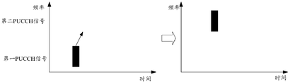
- FIG. 2 is a scene diagram of a signal transmission method according to an exemplary embodiment
- FIG. 3 is a schematic diagram showing a signal transmission manner according to an exemplary embodiment
- FIG. 4 is a schematic diagram of signal time domain processing, according to an exemplary embodiment
- FIG. 5 is another schematic diagram of signal time domain processing, according to an exemplary embodiment
- FIG. 6 is another schematic diagram of signal time domain processing, according to an exemplary embodiment
- FIG. 7 is another schematic diagram of a signal transmission manner according to an exemplary embodiment
- FIG. 8 is a schematic diagram of signal frequency domain processing according to an exemplary embodiment
- FIG. 9 is a flowchart of a signal transmission method according to an exemplary embodiment
- FIG. 10 is a block diagram of a signal transmission apparatus according to an exemplary embodiment
- FIG. 11 is a block diagram of another signal transmission apparatus according to an exemplary embodiment.
- FIG. 12 is a block diagram of another signal transmission apparatus according to an exemplary embodiment
- FIG. 13 is a block diagram of another signal transmission apparatus according to an exemplary embodiment
- FIG. 14 is a block diagram of another signal transmission apparatus according to an exemplary embodiment
- FIG. 15 is a block diagram of another signal transmission apparatus according to an exemplary embodiment.
- FIG. 16 is a block diagram showing a signal transmission apparatus according to an exemplary embodiment
- FIG. 17 is a block diagram of another signal transmission apparatus according to an exemplary embodiment.
- FIG. 18 is a block diagram of another signal transmission apparatus according to an exemplary embodiment.
- FIG. 19 is a schematic structural diagram of a signal transmission apparatus according to an exemplary embodiment
- FIG. 20 is a schematic structural diagram of a signal transmission apparatus according to an exemplary embodiment.
- the terms first, second, third, etc. may be used in the present disclosure to describe various information, such information should not be limited to these terms. These terms are only used to distinguish the same type of information from each other.
- the indication information may also be referred to as second information without departing from the scope of the present disclosure.
- the second information may also be referred to as indication information.
- the word "if” as used herein may be interpreted as "when” or "when” or "in response to determination.”
- FIG. 1 is a flowchart of a signal transmission method according to an exemplary embodiment
- FIG. 2 is a scene diagram of a signal transmission method according to an exemplary embodiment
- the signal transmission method may be used for a terminal, such as As shown in FIG. 1, the signal transmission method includes the following steps 110-130:
- step 110 the first PUCCH signal and the second PUCCH signal to be combined are obtained.
- the transmission duration of the first PUCCH signal is a specified symbol, and the transmission duration of the second PUCCH signal is greater than a specified symbol.
- the first PUCCH signal and the second PUCCH signal may correspond to different service types.
- the transmission duration of the first PUCCH signal is short, and only one symbol can correspond to a URLLC type service;
- the second PUCCH signal has a long transmission duration, for example, 14 symbols, which can correspond to an eMBB type service.
- the PUCCH signals of different transmission durations and different transmission formats need to be transmitted at the same time, for this situation.
- the user terminal performs a combining process on the first PUCCH signal and the second PUCCH signal to obtain a third PUCCH signal, and then sends the third PUCCH signal to the base station.
- a third PUCCH signal is obtained by using a first PUCCH signal instead of a DMRS (Demodulation Reference Signal) of at least one specified symbol in the second PUCCH signal.
- DMRS Demodulation Reference Signal
- the combining process of the first PUCCH signal and the second PUCCH signal is: directly replacing the DMRS of one or more specified symbols in the second PUCCH signal by using the first PUCCH signal to obtain a third PUCCH signal.
- the second PUCCH signal includes UCI (Uplink Control Information) and DMRS.
- the third PUCCH signal is transmitted to the base station, so that the base station recovers the first PUCCH signal from the third PUCCH signal, and uses the first PUCCH signal as the DMRS in the second PUCCH signal to perform the second PUCCH signal. Demodulation, obtaining the UCI carried by the second PUCCH signal.
- a base station and a terminal are included.
- the terminal acquires the first PUCCH signal and the second PUCCH signal of different transmission durations, directly uses the first PUCCH signal to replace the DMRS in the second PUCCH signal, obtains a third PUCCH signal, and then transmits the third PUCCH signal to the base station; the base station receives After the third PUCCH signal, the first PUCCH signal is recovered from the third PUCCH signal, and the first PUCCH signal is demodulated as the DMRS in the second PUCCH signal to obtain the second PUCCH signal.
- UCI User Service Call
- the first PUCCH signal and the second PUCCH are transmitted by acquiring the to-be-combined transmission.
- a signal the transmission duration of the first PUCCH signal is a designated symbol
- the transmission duration of the second PUCCH signal is greater than a specified symbol
- the third PUCCH signal is obtained by using the first PUCCH signal instead of the DMRS in the second PUCCH signal
- the third The PUCCH signal is transmitted to the base station, thereby solving the transmission conflict problem that occurs when the terminal simultaneously transmits the PUCCH signals of different transmission durations, improves the transmission quality of the uplink control signal, and improves the signal transmission efficiency.
- the designated symbol may be an OFDM (Orthogonal Frequency Division Multiplexing) symbol or an SCFDMA (Single-Carrier Frequency-Division Multiple Access). symbol.
- OFDM Orthogonal Frequency Division Multiplexing
- SCFDMA Single-Carrier Frequency-Division Multiple Access
- the designated symbol can be an OFDM symbol or an SCFDMA symbol, thereby enriching the expression form of the transmission duration, expanding the use field of signal transmission, and improving the practicality of signal transmission.
- the transmission format of the second PUCCH signal may be UCI and DMRS arranged in a specified order in the time domain, and the UCI and the DMRS in the specified order are respectively located on different symbols in the time domain, such as UCI and DMRS are alternately arranged in 1:1, as shown in FIG. 3.
- UCI and DMRS have other sorting orders, for example, UUDUUDUUUDUUDU, where U refers to UCI, and D refers to DMRS.
- the first PUCCH signal and the UCI in the second PUCCH signal overlap in the time domain
- the first PUCCH signal is used to replace the DMRS after the coincident UCI; and the first PUCCH signal and the second PUCCH signal are used.
- the DMRS in the time domain overlaps, and the first PUCCH signal is used to replace the coincident DMRS, thereby implementing the function of replacing the DMRS in the second PUCCH signal by using the first PUCCH signal, and completing the first PUCCH signal and the first
- the combined processing of the two PUCCH signals in the time domain improves the reliability of signal transmission.
- the transmission format of the first PUCCH signal may include any one of the following:
- the transmission format of the first PUCCH signal is to characterize different UCIs using different sequences.
- the corresponding transmission format may be to use different sequences to characterize different UCIs.
- a sequence N1 may be used to represent "0"
- a sequence N2 may be used to represent "1”
- a base station side may detect N1 and N2 to determine UCE information;
- UCI can use 4 sequences to represent the possible UCI information in 4.
- the base station side needs to detect the sequence of the first PUCCH signal first, and then demodulate the DMRS using the detected sequence as the second PUCCH signal.
- the transmission format of the first PUCCH signal is arranged in the frequency domain by the specified arrangement density using DMRS and UCI.
- the corresponding transmission format may be arranged in the frequency domain by a specified arrangement density using DMRS and UCI.
- the specified arrangement density is an arrangement form of DMRS and UCI in the frequency domain. For example, if the specified arrangement density is 1/3, then two UCIs are arranged after one DMRS, as shown in FIG. 6.
- the transmission format of the first PUCCH signal may be different using different sequences to represent different UCIs, or may be arranged in the frequency domain by using DMRS and UCI according to a specified arrangement density, thereby enriching the first PUCCH signal.
- the transmission format satisfies the different transmission requirements of the first PUCCH signal, and improves the efficiency of signal transmission.
- the symbols on certain fixed locations of different sequences may be made the same.
- the sequence design of the first PUCCH signal uses a CAZAC (Const Amplitude Zero Auto-Corelation) sequence in LTE
- CAZAC Const Amplitude Zero Auto-Corelation
- different cyclic shifts of the same sequence can be used as representing different UCIs.
- the second PUCCH signal can be demodulated by using the same symbol at one or more specified locations as the DMRS symbol, so that the base station can avoid the dependence on the first PUCCH signal recovery when demodulating the second PUCCH signal.
- the adverse effect of demodulating the second PUCCH signal due to erroneous recovery of the first PUCCH signal can be avoided.
- the method may further include:
- the number of the first PRB (Physical Resource Block) occupied by the first PUCCH signal is greater than the second PRB occupied by the second PUCCH signal.
- the following processing manners may be used:
- (4-1) adjusting the first PRB number, the adjusted PRB number is the same as the second PRB number, and adjusting the transmission format of the first PUCCH under the adjusted PRB number, for example, using a shorter sequence length or using more High modulation coding efficiency; or
- (4-2) not adjusting the first PRB number and the transmission format of the first PUCCH, but adjusting the starting position of the frequency domain transmission of the first PUCCH signal, the starting position being the frequency domain transmission of the second PUCCH signal The difference between the starting position and the specified offset value.
- the specified offset value may be a preset fixed value or a value configured by the base station by using a downlink instruction.
- the specified offset value is less than or equal to the difference between the first PRB number and the second PRB number, so as to ensure that the first PUCCH signal can occupy the frequency domain PRB of the second PUCCH signal.
- the scheduling of the first PUCCH signal by the base station should ensure that it is not interfered with the uplink transmission of other user terminals when it is combined with the second PUCCH signal, and has a certain impact on the flexibility of the base station scheduling.
- the adjusted PRB number is the same as the second PRB number, or the starting position of the frequency domain transmission of the first PUCCH signal is adjusted, where the starting position is the second PUCCH signal.
- the difference between the start position of the frequency domain transmission and the specified offset value thereby avoiding the uplink transmission to other users when the first PRB number occupied by the first PUCCH signal is greater than the second PRB number occupied by the second PUCCH signal. Interference, which in turn improves the transmission quality of the signal.
- the preset condition is that the first PRB number occupied by the first PUCCH signal is smaller than the second PRB number occupied by the second PUCCH signal, the first PUCCH signal and the first When the two PUCCH signals are processed in the corresponding frequency domain, the following processing methods may be used:
- the number of PRBs used for the first PUCCH signal transmission can be changed and transmitted using the same number of PRBs as the second PUCCH signal.
- a longer length or a sequence length matching the number of PRBs of the second PUCCH signal is used for transmission; for a first PUCCH signal with a UCI number greater than 2 bits, UCI is encoded using a lower coding rate.
- the first PUCCH signal occupies the frequency domain bandwidth of the second PUCCH signal in the form of a comb (comb) transmission, as shown in the third mode in FIG. 8; or
- the first PUCCH signal occupies a part of the PRB of the second PUCCH signal, and the other unoccupied PRB is used to transmit the DMRS of the second PUCCH signal, as shown in mode four in FIG.
- the adjusted number of PRBs is the same as the number of the second PRBs, or the first PUCCH signal is repeated in the frequency domain until the frequency of the second PUCCH signal is occupied.
- the first PUCCH signal occupies the frequency domain bandwidth of the second PUCCH signal in the form of a comb transmission, or the first PUCCH signal occupies a part of the PRB of the second PUCCH signal, and other unoccupied PRBs are used for transmission.
- step 130 when step 130 is performed, the following transmission modes may be used:
- (6-3) transmitting the third PUCCH signal to the base station using another power control method or parameter different from both the first PUCCH signal and the second PUCCH signal.
- the third PUCCH signal can be transmitted to the base station by using the power control method or parameter of the first PUCCH signal, or the power control method or parameter of the second PUCCH signal, or another power control method or parameter. This enriches the signal transmission implementation and improves the controllability of signal transmission.
- FIG. 9 is a flowchart of a signal transmission method according to an exemplary embodiment.
- the signal transmission method may be used in a base station. As shown in FIG. 9, the signal transmission method includes the following steps 910-930:
- the PUCCH signal is sent by the terminal, where the PUCCH signal is a third PUCCH signal obtained by the terminal using the first PUCCH signal instead of the DMRS in the second PUCCH signal, and the transmission duration of the first PUCCH signal is a designated symbol.
- the transmission duration of the second PUCCH signal is greater than one designated symbol.
- the transmission durations of the first PUCCH signal and the second PUCCH signal are different.
- the transmission duration of the first PUCCH signal is one specified symbol (symbol)
- the transmission duration of the second PUCCH signal is 14 symbols.
- the designated symbol may specify an OFDM symbol or an SCFDMA symbol.
- step 920 the first PUCCH signal is recovered from the third PUCCH signal.
- the base station may recover the first PUCCH signal and the UCI carried by the first PUCCH signal from the third PUCCH signal.
- the first PUCCH signal is used as a DMRS in the second PUCCH signal to demodulate the second PUCCH signal to obtain a UCI carried by the second PUCCH signal.
- the PUCCH signal is a third PUCCH signal obtained by the terminal by using the first PUCCH signal instead of the DMRS in the second PUCCH signal, and the transmission duration of the first PUCCH signal is a specified. a symbol, the transmission duration of the second PUCCH signal is greater than one specified symbol, and the first PUCCH signal is recovered from the third PUCCH signal, and the first PUCCH signal is used.
- the second PUCCH signal is demodulated to obtain the UCI carried by the second PUCCH signal, thereby realizing the UCI carried out by demodulating the second PUCCH signal from the combined processed signal, thereby improving the UCI. The reliability of signal transmission.
- the transmission format of the first PUCCH signal is to use different sequences to represent different UCIs, and the symbols in one or more specified positions in the different sequences are the same, after performing step 310, The following demodulation methods are used:
- the first PUCCH signal is not recovered from the third PUCCH signal, but the second PUCCH signal is demodulated by directly using the same symbol in one or more specified positions in the first PUCCH signal as the DMRS in the second PUCCH signal. UCI carried by the second PUCCH signal.
- the transmission format of the first PUCCH signal is to use different sequences to represent different UCIs, and the symbols in one or more specified positions in the different sequences are the same, the first PUCCH signal may be utilized.
- the same symbol at one or more specified locations demodulates the second PUCCH signal as a DMRS in the second PUCCH signal without restoring the first PUCCH signal, thus avoiding demodulating the second PUCCH signal for the first PUCCH
- the dependence of the signal recovery can further avoid the adverse effect of demodulating the second PUCCH signal due to the error recovery of the first PUCCH signal, thereby enriching the demodulation mode of the base station and improving the demodulation efficiency of the signal.
- the following demodulation mode may be adopted:
- the first PUCCH signal is not recovered from the third PUCCH signal, but the DMRS symbol at the DMRS position on the first PUCCH signal is used as a DMRS in the second PUCCH signal to demodulate the second PUCCH signal to obtain a second PUCCH signal. Carrying UCI.
- the DMRS symbol at the DMRS position on the first PUCCH signal can be used as the second PUCCH signal.
- the DMRS demodulates the second PUCCH signal without recovering the first PUCCH signal, so that the dependence on the first PUCCH signal recovery when demodulating the second PUCCH signal can be avoided, thereby avoiding recovering the first PUCCH signal due to an error.
- the detrimental effect on demodulating the second PUCCH signal enriches the demodulation mode of the base station and improves the demodulation efficiency of the signal.
- the present disclosure also provides an embodiment of a signal transmission device.
- FIG. 10 is a block diagram of a signal transmission apparatus for a terminal and for performing the signal transmission method shown in FIG. 1 according to an exemplary embodiment.
- the signal transmission apparatus may include:
- the obtaining module 101 is configured to obtain a first uplink control channel PUCCH signal and a second PUCCH signal to be combined and transmitted, where a transmission duration of the first PUCCH signal is a designated symbol, and a transmission duration of the second PUCCH signal is greater than a specified symbol;
- the time domain processing module 102 is configured to use the first PUCCH signal to replace the demodulation reference signal DMRS of the at least one specified symbol in the second PUCCH signal to obtain a third PUCCH signal;
- the transmitting module 103 is configured to transmit the third PUCCH signal to the base station, so that the base station recovers the first PUCCH signal from the third PUCCH signal, and uses the first PUCCH signal as the The DMRS in the second PUCCH signal demodulates the second PUCCH signal to obtain a UCI carried by the second PUCCH signal.
- the transmission duration of the first PUCCH signal is a designated symbol, and the transmission duration of the second PUCCH signal is greater than a specified symbol, and the first The PUCCH signal is used to replace the DMRS in the second PUCCH signal to obtain a third PUCCH signal, and the third PUCCH signal is transmitted to the base station, thereby solving the transmission conflict problem that occurs when the terminal simultaneously transmits the PUCCH signals of different transmission durations, and improves the uplink control signal.
- the transmission quality also improves the signal transmission efficiency.
- the designated symbol is an orthogonal frequency division multiplexing OFDM symbol, or a single carrier frequency division multiplexing SCFDMA symbol.
- the designated symbol can be an OFDM symbol or an SCFDMA symbol, thereby enriching the expression form of the transmission duration, expanding the use field of signal transmission, and improving the practicality of signal transmission.
- the transmission format of the second PUCCH signal is UCI and DMRS are arranged in a specified order in the time domain;
- the time domain processing module 102 may include:
- the first time domain processing sub-module 111 is configured to delay transmission of the first PUCCH signal and use the first if the first PUCCH signal and the UCI in the second PUCCH signal overlap in the time domain Substituting a PUCCH signal for the DMRS after the coincident UCI, and transmitting the first PUCCH signal on a time frequency resource that the DMRS should occupy;
- the second time domain processing sub-module 112 is configured to replace the coincident DMRS with the first PUCCH signal if the DMRS in the first PUCCH signal and the second PUCCH signal overlap in the time domain, And transmitting the first PUCCH signal on a time frequency resource that the DMRS should occupy.
- the first PUCCH signal and the UCI in the second PUCCH signal overlap in the time domain
- the first PUCCH signal is used to replace the DMRS after the coincident UCI; and the first PUCCH signal and the second PUCCH signal are used.
- the DMRS in the time domain overlaps, and the first PUCCH signal is used to replace the coincident DMRS, thereby implementing the function of replacing the DMRS in the second PUCCH signal by using the first PUCCH signal, and completing the first PUCCH signal and the first
- the combined processing of the two PUCCH signals in the time domain improves the reliability of signal transmission.
- the transmission format of the first PUCCH signal includes any one of the following:
- the transmission format of the first PUCCH signal is to use different sequences to represent different UCIs.
- the transmission format of the first PUCCH signal is arranged in the frequency domain by a specified arrangement density using DMRS and UCI.
- the transmission format of the first PUCCH signal may be different using different sequences to represent different UCIs, or may be arranged in the frequency domain by using DMRS and UCI according to a specified arrangement density, thereby enriching the first PUCCH signal.
- the transmission format satisfies the different transmission requirements of the first PUCCH signal, and improves the efficiency of signal transmission.
- the symbols at one or more of the specified positions are the same.
- the second PUCCH signal can be demodulated by using the same symbol at one or more specified locations as the DMRS symbol, so that the base station can avoid the dependence on the first PUCCH signal recovery when demodulating the second PUCCH signal.
- the adverse effect of demodulating the second PUCCH signal due to erroneous recovery of the first PUCCH signal can be avoided.
- the signal transmission apparatus may further include:
- the frequency domain processing module 121 is configured to: if the first PUCCH signal and the second PUCCH signal meet a preset condition in a frequency domain, perform corresponding to the first PUCCH signal and the second PUCCH signal Frequency domain processing.
- the preset condition is occupied by the first PUCCH signal.
- the first frequency domain processing sub-module 131 is configured to include at least one of the following processing modes:
- Adjusting the first PRB number, the adjusted PRB number is the same as the second PRB number, and adjusting a transmission format of the first PUCCH under the adjusted PRB number;
- the adjusted PRB number is the same as the second PRB number, or the starting position of the frequency domain transmission of the first PUCCH signal is adjusted, where the starting position is the second PUCCH signal.
- the difference between the start position of the frequency domain transmission and the specified offset value thereby avoiding the uplink transmission to other users when the first PRB number occupied by the first PUCCH signal is greater than the second PRB number occupied by the second PUCCH signal. Interference, which in turn improves the transmission quality of the signal.
- the preset condition is that the first PRB number occupied by the first PUCCH signal is smaller than the second PRB number occupied by the second PUCCH signal;
- the frequency domain processing module 121 can include:
- the second frequency domain processing sub-module 141 is configured to include at least one of the following processing modes:
- Adjusting the first PRB number, the adjusted PRB number is the same as the second PRB number, and adjusting a transmission format of the first PUCCH under the adjusted PRB number;
- the first PUCCH signal is repeated in the frequency domain until the frequency domain bandwidth of the second PUCCH signal is occupied;
- the first PUCCH signal occupies a frequency domain bandwidth of the second PUCCH signal in the form of a comb transmission
- the first PUCCH signal occupies a part of the PRB of the second PUCCH signal, and the other unoccupied PRBs are used to transmit the DMRS of the second PUCCH signal.
- the adjusted number of PRBs is the same as the number of the second PRBs, or the first PUCCH signal is repeated in the frequency domain until the frequency of the second PUCCH signal is occupied.
- the domain bandwidth, or the frequency of the first PUCCH signal in the form of comb transmission to occupy the second PUCCH signal The domain bandwidth, or the first PUCCH signal occupies a part of the PRB of the second PUCCH signal, and the other unoccupied PRB is used to transmit the DMRS of the second PUCCH signal, thereby solving that the first PRB number occupied by the first PUCCH signal is smaller than the first
- the second PUB number of the second PUCCH signal is occupied, the first PUCCH signal cannot completely occupy the frequency domain PRB of the second PUCCH signal, thereby improving the efficiency of signal transmission.
- the transmission module 103 may include:
- the transmission submodule 151 is configured to include at least one of the following transmission modes:
- the third PUCCH signal is transmitted to the base station using another power control method or parameter that is different from both the first PUCCH signal and the second PUCCH signal.
- the third PUCCH signal can be transmitted to the base station by using the power control method or parameter of the first PUCCH signal, or the power control method or parameter of the second PUCCH signal, or another power control method or parameter. This enriches the signal transmission implementation and improves the controllability of signal transmission.
- FIG. 16 is a block diagram of a signal transmission apparatus for a base station and for performing the signal transmission method shown in FIG. 9 according to an exemplary embodiment.
- the signal transmission apparatus may include:
- the receiving module 161 is configured to receive an uplink control channel PUCCH signal sent by the terminal, where the PUCCH signal is a third obtained by the terminal by using the first PUCCH signal instead of the demodulation reference signal DMRS in the second PUCCH signal.
- a PUCCH signal the transmission duration of the first PUCCH signal is a designated symbol, and the transmission duration of the second PUCCH signal is greater than a specified symbol;
- the recovery module 162 is configured to recover the first PUCCH signal from the third PUCCH signal
- the first demodulation module 163 is configured to demodulate the second PUCCH signal by using the first PUCCH signal as a DMRS in the second PUCCH signal to obtain a UCI carried by the second PUCCH signal.
- the PUCCH signal is received by the terminal, and the PUCCH signal is a third PUCCH signal obtained by the terminal by using the first PUCCH signal instead of the DMRS in the second PUCCH signal.
- the transmission duration of the first PUCCH signal is a specified symbol
- the transmission duration of the second PUCCH signal is greater than one designated symbol
- the first PUCCH signal is recovered from the third PUCCH signal
- the first PUCCH signal is used as the second PUCCH signal.
- the DMRS demodulates the second PUCCH signal to obtain the UCI carried by the second PUCCH signal, thereby realizing demodulation of the UCI carried by the second PUCCH signal from the combined processed signal, thereby improving the reliability of signal transmission.
- the transmission format of the first PUCCH signal is to use different sequences to represent different UCIs, and the symbols in one or more specified positions in the different sequences are the same.
- the device may also include:
- the second demodulation module 171 is configured to not recover the first PUCCH signal from the third PUCCH signal, but directly utilize the same symbol in one or more specified positions in the first PUCCH signal as the
- the DMRS in the second PUCCH signal demodulates the second PUCCH signal to obtain a UCI carried by the second PUCCH signal.
- the transmission format of the first PUCCH signal is to use different sequences to represent different UCIs, and the symbols in one or more specified positions in the different sequences are the same, the first PUCCH signal may be utilized.
- the same symbol at one or more specified locations demodulates the second PUCCH signal as a DMRS in the second PUCCH signal without restoring the first PUCCH signal, thus avoiding demodulating the second PUCCH signal for the first PUCCH
- the dependence of the signal recovery can further avoid the adverse effect of demodulating the second PUCCH signal due to the error recovery of the first PUCCH signal, thereby enriching the demodulation mode of the base station and improving the demodulation efficiency of the signal.
- the transmission format of the first PUCCH signal is arranged by using a DMRS and a UCI in a frequency domain according to a specified arrangement density; the apparatus may further include:
- the third demodulation module 181 is configured to not recover the first PUCCH signal from the third PUCCH signal, but use the DMRS symbol at the DMRS position on the first PUCCH signal as the second PUCCH
- the DMRS in the signal demodulates the second PUCCH signal to obtain a UCI carried by the second PUCCH signal.
- the DMRS symbol at the DMRS position on the first PUCCH signal can be used as the second PUCCH signal.
- the DMRS demodulates the second PUCCH signal without recovering the first PUCCH signal, so as to avoid the first PUCCH signal when demodulating the second PUCCH signal.
- the dependency of the recovery may further avoid the adverse effect of demodulating the second PUCCH signal due to the error recovery of the first PUCCH signal, thereby enriching the demodulation mode of the base station and improving the demodulation efficiency of the signal.
- the device embodiment since it basically corresponds to the method embodiment, reference may be made to the partial description of the method embodiment.
- the device embodiments described above are merely illustrative, wherein the units described as separate components may or may not be physically separated, and the components displayed as units may or may not be physical units, ie may be located in one Places, or they can be distributed to multiple network elements. Some or all of the modules may be selected according to actual needs to achieve the objectives of the present disclosure. Those of ordinary skill in the art can understand and implement without any creative effort.
- the present disclosure also provides a non-transitory computer readable storage medium having stored thereon a computer program for performing the signal transmission method of any of the above-described FIGS. 1 to 8.
- the present disclosure also provides a non-transitory computer readable storage medium having stored thereon a computer program for performing the signal transmission method described above with reference to FIG.
- the present disclosure also provides a signal transmission device for a terminal, the device comprising:
- a memory for storing processor executable instructions
- processor is configured to:
- the transmission duration of the first PUCCH signal is a designated symbol, and the transmission duration of the second PUCCH signal is greater than a specified symbol;
- FIG. 19 is a schematic structural diagram of a signal transmission apparatus according to an exemplary embodiment.
- a signal transmission device 1900 according to an exemplary embodiment, which may be a computer, a mobile phone, a digital broadcast terminal, a messaging device, a game console, a tablet device, a medical device, and a fitness device.
- apparatus 1900 can include one or more of the following components: processing component 1901, memory 1902, power component 1903, multimedia component 1904, audio component 1905, input/output (I/O) interface 1906, sensor component 1907, And a communication component 1908.
- Processing component 1901 typically controls the overall operation of device 1900, such as operations associated with display, telephone calls, data communications, camera operations, and recording operations.
- Processing component 1901 can include one or more processors 1909 to execute instructions to perform all or part of the steps of the above described methods.
- processing component 1901 can include one or more modules to facilitate interaction between component 1901 and other components.
- the processing component 1901 can include a multimedia module to facilitate interaction between the multimedia component 1904 and the processing component 1901.
- Memory 1902 is configured to store various types of data to support operation at device 1900. Examples of such data include instructions for any application or method operating on device 1900, contact data, phone book data, messages, pictures, videos, and the like.
- the memory 1902 can be implemented by any type of volatile or non-volatile storage device, or a combination thereof, such as static random access memory (SRAM), electrically erasable programmable read only memory (EEPROM), erasable. Programmable Read Only Memory (EPROM), Programmable Read Only Memory (PROM), Read Only Memory (ROM), Magnetic Memory, Flash Memory, Disk or Optical Disk.
- SRAM static random access memory
- EEPROM electrically erasable programmable read only memory
- EPROM Electrically erasable programmable read only Memory
- PROM Programmable Read Only Memory
- ROM Read Only Memory
- Magnetic Memory Flash Memory
- Disk Disk or Optical Disk.
- Power component 1903 provides power to various components of device 1900.
- Power component 1903 can include a power management system, one or more power sources, and other components associated with generating, managing, and distributing power for device 1900.
- Multimedia component 1904 includes a screen between the device 1900 and a user that provides an output interface.
- the screen can include a liquid crystal display (LCD) and a touch panel (TP). If the screen includes a touch panel, the screen can be implemented as a touch screen to receive input signals from the user.
- the touch panel includes one or more touch sensors to sense touches, slides, and gestures on the touch panel. The touch sensor may sense not only the boundary of the touch or sliding action, but also the duration and pressure associated with the touch or slide operation.
- the multimedia component 1904 includes a front camera and/or a rear camera. When the device 1900 is in an operation mode, such as a shooting mode or a video mode, the front camera and/or the rear camera can receive external multimedia data. Each front and rear camera can be a fixed optical lens system or have focal length and optical zoom capabilities.
- the audio component 1905 is configured to output and/or input an audio signal.
- audio component 1905 includes a microphone (MIC) that is configured to receive an external audio signal when device 1900 is in an operational mode, such as a call mode, a recording mode, and a voice recognition mode.
- the received audio signal may be further stored in memory 1902 or transmitted via communication component 1908.
- the audio component 1905 also includes a Speaker for outputting audio signals.
- the I/O interface 1906 provides an interface between the processing component 1901 and a peripheral interface module, which may be a keyboard, a click wheel, a button, or the like. These buttons may include, but are not limited to, a home button, a volume button, a start button, and a lock button.
- Sensor assembly 1907 includes one or more sensors for providing state assessment of various aspects to device 1900.
- sensor assembly 1907 can detect an open/closed state of device 1900, relative positioning of components, such as the display and keypad of device 1900, and sensor component 1907 can also detect changes in position of one component of device 1900 or device 1900. The presence or absence of contact by the user with the device 1900, the orientation or acceleration/deceleration of the device 1900 and the temperature change of the device 1900.
- Sensor assembly 1907 can include a proximity sensor configured to detect the presence of nearby objects without any physical contact.
- Sensor assembly 1907 can also include a light sensor, such as a CMOS or CCD image sensor, for use in imaging applications.
- the sensor assembly 1907 can also include an acceleration sensor, a gyro sensor, a magnetic sensor, a pressure sensor, or a temperature sensor.
- Communication component 1908 is configured to facilitate wired or wireless communication between device 1900 and other devices.
- the device 1900 can access a wireless network based on a communication standard, such as WiFi, 2G or 3G, or a combination thereof.
- communication component 1908 receives broadcast signals or broadcast associated information from an external broadcast management system via a broadcast channel.
- the communication component 1908 also includes a near field communication (NFC) module to facilitate short range communication.
- NFC near field communication
- the NFC module can be implemented based on radio frequency identification (RFID) technology, infrared data association (IrDA) technology, ultra-wideband (UWB) technology, Bluetooth (BT) technology, and other technologies.
- RFID radio frequency identification
- IrDA infrared data association
- UWB ultra-wideband
- Bluetooth Bluetooth
- device 1900 may be implemented by one or more application specific integrated circuits (ASICs), digital signal processors (DSPs), digital signal processing devices (DSPDs), programmable logic devices (PLDs), field programmable A gate array (FPGA), controller, microcontroller, microprocessor or other electronic component implementation for performing the above methods.
- ASICs application specific integrated circuits
- DSPs digital signal processors
- DSPDs digital signal processing devices
- PLDs programmable logic devices
- FPGA field programmable A gate array
- controller microcontroller, microprocessor or other electronic component implementation for performing the above methods.
- non-transitory computer readable storage medium comprising instructions, such as a memory 1902 comprising instructions executable by processor 1909 of apparatus 1900 to perform the above method.
- the non-transitory computer readable storage medium can be a ROM, a random access memory (RAM), a CD-ROM, a magnetic tape, a floppy disk, and an optical data storage device.
- the device 1900 is enabled to execute The signal transmission method of any of the above.
- the present disclosure also provides a signal transmission apparatus for a base station, the apparatus comprising:
- a memory for storing processor executable instructions
- processor is configured to:
- the PUCCH signal is a third PUCCH signal obtained by the terminal by using the first PUCCH signal to replace the demodulation reference signal DMRS in the second PUCCH signal, where the first PUCCH signal is The transmission duration is a specified symbol, and the transmission duration of the second PUCCH signal is greater than a specified symbol;
- FIG. 20 is a schematic structural diagram of a signal transmission apparatus according to an exemplary embodiment.
- Apparatus 2000 can be provided as a base station.
- apparatus 2000 includes a processing component 2022, a wireless transmit/receive component 2024, an antenna component 2026, and a signal processing portion specific to the wireless interface.
- Processing component 2022 can further include one or more processors.
- One of the processing components 2022 can be configured to perform the signal transmission method of any of the above.
Abstract
L'invention concerne un procédé et un dispositif d'émission de signal. Le procédé est appliqué à un terminal, et consiste à : acquérir un premier signal PUCCH et un deuxième signal PUCCH, la durée d'émission du premier signal PUCCH étant un symbole désigné, et la durée d'émission du deuxième signal PUCCH étant supérieure à un symbole désigné; remplacer le signal de référence de démodulation, DMRS, d'au moins un symbole désigné dans le deuxième signal PUCCH par le premier signal PUCCH pour obtenir un troisième signal PUCCH; et émettre le troisième signal PUCCH à une station de base, de telle sorte que la station de base récupère le premier signal PUCCH à partir du troisième signal PUCCH, et démodule le deuxième signal PUCCH en prenant le premier signal PUCCH en tant que DMRS du deuxième signal PUCCH de façon à obtenir des informations de commande de liaison montante, UCI, transportées par le deuxième signal PUCCH. Par conséquent, selon la présente invention, le problème de collision d'émission qui se produit lorsqu'un terminal émet simultanément des signaux PUCCH de différentes durées d'émission peut être résolu.
Priority Applications (4)
| Application Number | Priority Date | Filing Date | Title |
|---|---|---|---|
| PCT/CN2017/104425 WO2019061306A1 (fr) | 2017-09-29 | 2017-09-29 | Procédé et dispositif d'émission de signal |
| US16/649,158 US11218287B2 (en) | 2017-09-29 | 2017-09-29 | Signal transmission method and device |
| EP17926587.1A EP3681068B1 (fr) | 2017-09-29 | 2017-09-29 | Procédé et dispositif d'émission de signal |
| CN201780001624.7A CN108401485B (zh) | 2017-09-29 | 2017-09-29 | 信号传输方法及装置 |
Applications Claiming Priority (1)
| Application Number | Priority Date | Filing Date | Title |
|---|---|---|---|
| PCT/CN2017/104425 WO2019061306A1 (fr) | 2017-09-29 | 2017-09-29 | Procédé et dispositif d'émission de signal |
Publications (1)
| Publication Number | Publication Date |
|---|---|
| WO2019061306A1 true WO2019061306A1 (fr) | 2019-04-04 |
Family
ID=63095075
Family Applications (1)
| Application Number | Title | Priority Date | Filing Date |
|---|---|---|---|
| PCT/CN2017/104425 WO2019061306A1 (fr) | 2017-09-29 | 2017-09-29 | Procédé et dispositif d'émission de signal |
Country Status (4)
| Country | Link |
|---|---|
| US (1) | US11218287B2 (fr) |
| EP (1) | EP3681068B1 (fr) |
| CN (1) | CN108401485B (fr) |
| WO (1) | WO2019061306A1 (fr) |
Cited By (1)
| Publication number | Priority date | Publication date | Assignee | Title |
|---|---|---|---|---|
| CN110971558A (zh) * | 2019-12-17 | 2020-04-07 | 西安电子科技大学 | 基于cazac序列的低复杂度抗频偏同步方法 |
Families Citing this family (4)
| Publication number | Priority date | Publication date | Assignee | Title |
|---|---|---|---|---|
| WO2020056584A1 (fr) * | 2018-09-18 | 2020-03-26 | 北京小米移动软件有限公司 | Procédé et dispositif de détermination de pucch nécessitant une transmission |
| CN113287279B (zh) * | 2019-01-11 | 2023-02-28 | 中兴通讯股份有限公司 | 高可靠性无线通信 |
| CN111836381B (zh) * | 2019-08-16 | 2023-09-08 | 维沃移动通信有限公司 | 传输方法、配置pucch的方法和设备 |
| US20230217432A1 (en) * | 2020-06-04 | 2023-07-06 | Beijing Xiaomi Mobile Software Co., Ltd. | Method and device for determining an uplink transmission resource for a demodulation reference signal |
Citations (5)
| Publication number | Priority date | Publication date | Assignee | Title |
|---|---|---|---|---|
| CN103378957A (zh) * | 2012-04-27 | 2013-10-30 | 北京三星通信技术研究有限公司 | 一种harq-ack信息传输方法 |
| CN103427940A (zh) * | 2012-05-20 | 2013-12-04 | 上海贝尔股份有限公司 | 传输上行控制信息的方法和装置 |
| WO2017113332A1 (fr) * | 2015-12-31 | 2017-07-06 | Nec Corporation | Procédés et appareils pour émettre et recevoir des informations de liaison montante |
| CN106954261A (zh) * | 2016-01-07 | 2017-07-14 | 夏普株式会社 | 上行参考信号传输方法和接收方法、以及用户设备和基站 |
| CN107113097A (zh) * | 2014-12-31 | 2017-08-29 | Lg 电子株式会社 | 在无线通信系统中发送ack/nack的方法和设备 |
Family Cites Families (8)
| Publication number | Priority date | Publication date | Assignee | Title |
|---|---|---|---|---|
| CN101925113B (zh) | 2009-06-12 | 2013-06-12 | 电信科学技术研究院 | 一种上行控制信道的传输处理方法及设备 |
| WO2012003643A1 (fr) * | 2010-07-09 | 2012-01-12 | Zte Wistron Telecom Ab | Procédé et appareil de réception de canal de commande de liaison montante physique dans un système lte |
| CN104185215B (zh) * | 2013-05-22 | 2017-11-14 | 普天信息技术研究院有限公司 | 控制信息的合并处理方法 |
| RU2719294C1 (ru) * | 2017-01-05 | 2020-04-17 | Телефонактиеболагет Лм Эрикссон (Пабл) | Устройство и узел в системе беспроводной связи для передачи управляющей информации восходящей линии связи |
| EP3662608A4 (fr) * | 2017-08-02 | 2020-12-30 | Apple Inc. | Conception de séquence et attribution de ressources pour pucch nr |
| CN109392101B (zh) | 2017-08-04 | 2020-08-25 | 维沃移动通信有限公司 | 一种数据传输方法、终端及基站 |
| KR20200037347A (ko) * | 2017-08-10 | 2020-04-08 | 샤프 가부시키가이샤 | 5G(5th GENERATION) NR(NEW RADIO)을 위한 긴 PUCCH(PHYSICAL UPLINK CONTROL CHANNEL) 설계의 슬롯 구조 |
| CN109525999B (zh) | 2017-09-18 | 2021-09-24 | 维沃移动通信有限公司 | Dmrs确定方法、配置方法、终端和基站 |
-
2017
- 2017-09-29 US US16/649,158 patent/US11218287B2/en active Active
- 2017-09-29 CN CN201780001624.7A patent/CN108401485B/zh active Active
- 2017-09-29 EP EP17926587.1A patent/EP3681068B1/fr active Active
- 2017-09-29 WO PCT/CN2017/104425 patent/WO2019061306A1/fr unknown
Patent Citations (5)
| Publication number | Priority date | Publication date | Assignee | Title |
|---|---|---|---|---|
| CN103378957A (zh) * | 2012-04-27 | 2013-10-30 | 北京三星通信技术研究有限公司 | 一种harq-ack信息传输方法 |
| CN103427940A (zh) * | 2012-05-20 | 2013-12-04 | 上海贝尔股份有限公司 | 传输上行控制信息的方法和装置 |
| CN107113097A (zh) * | 2014-12-31 | 2017-08-29 | Lg 电子株式会社 | 在无线通信系统中发送ack/nack的方法和设备 |
| WO2017113332A1 (fr) * | 2015-12-31 | 2017-07-06 | Nec Corporation | Procédés et appareils pour émettre et recevoir des informations de liaison montante |
| CN106954261A (zh) * | 2016-01-07 | 2017-07-14 | 夏普株式会社 | 上行参考信号传输方法和接收方法、以及用户设备和基站 |
Non-Patent Citations (1)
| Title |
|---|
| See also references of EP3681068A4 * |
Cited By (2)
| Publication number | Priority date | Publication date | Assignee | Title |
|---|---|---|---|---|
| CN110971558A (zh) * | 2019-12-17 | 2020-04-07 | 西安电子科技大学 | 基于cazac序列的低复杂度抗频偏同步方法 |
| CN110971558B (zh) * | 2019-12-17 | 2021-07-06 | 西安电子科技大学 | 基于cazac序列的低复杂度抗频偏同步方法 |
Also Published As
| Publication number | Publication date |
|---|---|
| EP3681068A4 (fr) | 2021-04-07 |
| US11218287B2 (en) | 2022-01-04 |
| EP3681068B1 (fr) | 2024-01-17 |
| US20200259628A1 (en) | 2020-08-13 |
| CN108401485A (zh) | 2018-08-14 |
| EP3681068A1 (fr) | 2020-07-15 |
| CN108401485B (zh) | 2021-01-29 |
Similar Documents
| Publication | Publication Date | Title |
|---|---|---|
| CN112953610B (zh) | 上行传输的方法及装置 | |
| US11483819B2 (en) | Data transmission method and apparatus and user equipment | |
| WO2019095223A1 (fr) | Procédé et dispositif de configuration de saut de fréquence | |
| WO2019061306A1 (fr) | Procédé et dispositif d'émission de signal | |
| WO2019024087A1 (fr) | Procédé d'obtention de la position de ressources temps-fréquence d'un ensemble de ressources de commande communes d'informations de système restantes | |
| WO2019136688A1 (fr) | Procédé et appareil de retour d'informations | |
| US11540242B2 (en) | Methods and apparatuses for transmitting and receiving reference signal, base station and user equipment | |
| WO2018195970A1 (fr) | Procédé et appareil de transmission et d'acquisition d'informations de commande de liaison descendante communes | |
| WO2018201469A1 (fr) | Procédé de transmission de signal, dispositif, appareil électronique et support de stockage lisible par ordinateur | |
| WO2019024039A1 (fr) | Procédé et dispositif d'indication de transmission multiplex de données multi-service, terminal, et station de base | |
| KR102380170B1 (ko) | 데이터 전송 방법, 장치 및 그 컴퓨터 판독 가능한 저장 매체 | |
| JP7397098B2 (ja) | 制御情報伝送方法及び装置 | |
| WO2019210468A1 (fr) | Procédé et dispositif d'émission et de démodulation de bloc de diffusion synchrone, station de base et équipement utilisateur | |
| WO2017197799A1 (fr) | Procédé et dispositif de communication | |
| WO2019024037A1 (fr) | Procédé et dispositif d'indication de transmission multiplex de données multi-service, terminal, et station de base | |
| CN115053567A (zh) | 上行传输方法及装置、存储介质 | |
| WO2019148465A1 (fr) | Procédé de transmission de signalisation de commande, et terminal et station de base | |
| WO2019095201A1 (fr) | Procédé et dispositif de mappage de ressources de couche physique, équipement d'utilisateur et station de base | |
| WO2019028606A1 (fr) | Procédé de transmission de données, dispositif et support d'informations lisible par ordinateur | |
| WO2019028856A1 (fr) | Procédé et dispositif d'indication de radiomessagerie | |
| WO2019028756A1 (fr) | Procédé et dispositif de configuration d'informations de commande de liaison descendante | |
| WO2019023880A1 (fr) | Procédé et dispositif permettant d'indiquer une direction de transmission | |
| CN110312311B (zh) | 信道配置方法及装置 | |
| CN109792321B (zh) | 数据传输方法及装置 | |
| WO2018201336A1 (fr) | Procédé et dispositif de réception et d'émission de canal de commande de liaison descendante |
Legal Events
| Date | Code | Title | Description |
|---|---|---|---|
| 121 | Ep: the epo has been informed by wipo that ep was designated in this application |
Ref document number: 17926587 Country of ref document: EP Kind code of ref document: A1 |
|
| NENP | Non-entry into the national phase |
Ref country code: DE |
|
| ENP | Entry into the national phase |
Ref document number: 2017926587 Country of ref document: EP Effective date: 20200407 |