WO2019058563A1 - 燃焼装置及び燃焼方法 - Google Patents
燃焼装置及び燃焼方法 Download PDFInfo
- Publication number
- WO2019058563A1 WO2019058563A1 PCT/JP2017/034586 JP2017034586W WO2019058563A1 WO 2019058563 A1 WO2019058563 A1 WO 2019058563A1 JP 2017034586 W JP2017034586 W JP 2017034586W WO 2019058563 A1 WO2019058563 A1 WO 2019058563A1
- Authority
- WO
- WIPO (PCT)
- Prior art keywords
- ammonia
- nozzle
- combustion
- gas
- pulverized coal
- Prior art date
- Legal status (The legal status is an assumption and is not a legal conclusion. Google has not performed a legal analysis and makes no representation as to the accuracy of the status listed.)
- Ceased
Links
Images






Classifications
-
- F—MECHANICAL ENGINEERING; LIGHTING; HEATING; WEAPONS; BLASTING
- F23—COMBUSTION APPARATUS; COMBUSTION PROCESSES
- F23C—METHODS OR APPARATUS FOR COMBUSTION USING FLUID FUEL OR SOLID FUEL SUSPENDED IN A CARRIER GAS OR AIR
- F23C1/00—Combustion apparatus specially adapted for combustion of two or more kinds of fuel simultaneously or alternately, at least one kind of fuel being either a fluid fuel or a solid fuel suspended in a carrier gas or air
- F23C1/12—Combustion apparatus specially adapted for combustion of two or more kinds of fuel simultaneously or alternately, at least one kind of fuel being either a fluid fuel or a solid fuel suspended in a carrier gas or air gaseous and pulverulent fuel
-
- F—MECHANICAL ENGINEERING; LIGHTING; HEATING; WEAPONS; BLASTING
- F23—COMBUSTION APPARATUS; COMBUSTION PROCESSES
- F23C—METHODS OR APPARATUS FOR COMBUSTION USING FLUID FUEL OR SOLID FUEL SUSPENDED IN A CARRIER GAS OR AIR
- F23C5/00—Disposition of burners with respect to the combustion chamber or to one another; Mounting of burners in combustion apparatus
- F23C5/08—Disposition of burners
-
- F—MECHANICAL ENGINEERING; LIGHTING; HEATING; WEAPONS; BLASTING
- F23—COMBUSTION APPARATUS; COMBUSTION PROCESSES
- F23D—BURNERS
- F23D17/00—Burners for combustion simultaneously or alternately of gaseous or liquid or pulverulent fuel
-
- F—MECHANICAL ENGINEERING; LIGHTING; HEATING; WEAPONS; BLASTING
- F23—COMBUSTION APPARATUS; COMBUSTION PROCESSES
- F23K—FEEDING FUEL TO COMBUSTION APPARATUS
- F23K5/00—Feeding or distributing other fuel to combustion apparatus
Definitions
- the present invention relates to a combustion apparatus and a combustion method.
- the present invention relates to a structure and a combustion method of a combustion apparatus suitable for power generation equipment such as a thermal power plant.
- Thermal power plants etc. have installed a boiler as a power generation facility.
- the boiler generates high-temperature and high-pressure steam using the heat produced by burning a fossil fuel such as coal, natural gas, light oil, heavy oil, etc. with a burner.
- burning these fossil fuels generates carbon dioxide, which causes global warming. For this reason, in recent years there has been a move to curb carbon dioxide in the form of carbon credits (emission allowances).
- LNG liquefied natural gas
- LPG liquefied petroleum gas
- LNG is used as fuel for thermal power plants.
- Gas fuels such as LNG need to be liquefied for convenience in transportation.
- ammonia is liquefied at about -33 degrees, so it has the advantage of being easier to liquefy than, for example, LNG requiring about -162 degrees of liquefaction and requiring less expensive equipment.
- a multiple fuel burning combustion apparatus which has a coaxial burner capable of co-firing mixed gas of natural gas and BOG (boil off gas) and pulverized coal inside the boiler (see, for example, Patent Document 2).
- the coaxial burner according to Patent Document 2 comprises an inner pipe for injecting a pulverized coal flame into the interior of a boiler, and surrounding the inner pipe, the flame of a mixed gas of natural gas and BOG being coaxial with the injected direction of the pulverized coal flame. It consists of an outer pipe that jets in the direction.
- ammonia has a low burning rate, specifically, for example, where the burning rate of propane gas is 40 cm / s, the burning rate of ammonia is only 8 cm / s (therefore, when burning ammonia) Flames will be longer).
- the present invention has been made in view of such problems, and an object thereof is to provide a combustion apparatus and a combustion method capable of suppressing the generation of nitrogen oxides and the incomplete combustion of ammonia as much as possible.
- the present inventors are a combustion apparatus for co-firing pulverized coal and ammonia inside a furnace, and a flame in which ammonia is burned is along the tangential direction of a virtual circle whose central axis is the injection direction of the combustion flame of pulverized coal.
- a flame in which ammonia is burned is along the tangential direction of a virtual circle whose central axis is the injection direction of the combustion flame of pulverized coal.
- a combustion apparatus is a combustion apparatus for co-firing pulverized coal and ammonia inside a furnace, and a first nozzle having a first injection port for injecting pulverized coal toward the inside of the furnace; And one or more second nozzles disposed around the first nozzle and having a second injection port for injecting ammonia toward the inside of the furnace, wherein the second injection port of the second nozzle is The combustion flame of ammonia is inclined and opened in the injection direction side of the combustion flame of pulverized coal along the tangential direction of the imaginary circle whose central axis is the injection direction of the combustion flame of pulverized coal.
- an ammonia gas supply pipe for transporting ammonia toward the second nozzle and the first nozzle are disposed at a central portion, and the ammonia gas is distributed from the ammonia gas supply pipe A first gas ring, wherein the second nozzle comprises a plurality of second nozzles disposed around the first nozzle, wherein the second nozzles are configured to receive ammonia gas from the first gas ring It may be supplied.
- an ammonia gas supply pipe for transporting ammonia toward the second nozzle, a gas fuel pipe for transporting gas fuel, and the first nozzle are disposed at a central portion, A second gas ring to which gas fuel is distributed from a gas fuel pipe, a single second nozzle disposed around the first nozzle, and a second gas ring disposed around the first nozzle and directed toward the inside of the furnace And a burner nozzle connecting the second gas ring to the second nozzle and the third nozzle, wherein the burner nozzle connected to the second nozzle is A gas fuel piping shut-off valve capable of opening and closing the flow path of the burner nozzle is provided, and the ammonia gas supply piping can inject ammonia from the second injection port in a state where the gas fuel piping shut-off valve is closed. To, may be directly bonded to the burner nozzle connected to said second nozzle.
- the combustion method according to the present invention is a combustion method used in the combustion apparatus according to any one of (1) to (3), in which pulverized coal and ammonia are co-fired in the furnace, and the first nozzle
- the mixed combustion rate of ammonia, which is injected so as to be combustible from the second nozzle, is 0.8% or more with respect to pulverized coal which is injected so as to be combustible from the above.
- the combustion apparatus is a combustion apparatus in which pulverized coal and ammonia are co-fired inside a furnace, and a flame in which ammonia is burned is a virtual circle whose central axis is the injection direction of the combustion flame in which pulverized coal is burned. Since the injection is performed along the tangential direction and inclined to the injection direction side of the combustion flame of pulverized coal, the combustion time of ammonia can be secured, and the incomplete combustion of ammonia can be suppressed as much as possible.
- the mixed combustion ratio of ammonia injected from the second nozzle to the combustible gas from the second nozzle is 0.8% or more with respect to pulverized coal injected from the first nozzle to the combustible gas, The occurrence of objects can be suppressed as much as possible.
- FIG. 14 (a) is a graph which shows the time change of coal usage-amount per unit time
- Fig. 14 (b) is a table showing the time change of the amount of coal used per unit time
- Fig. 14 (b) is a table showing the time change of the amount of coal used per unit time
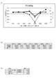
- FIG. 14 (c) is a table showing the time change of the average output of the power generation facility. It is a figure which shows the measurement point which measured the ammonia concentration of the exit of a combustion apparatus using the combustion apparatus by 3rd Embodiment. It is a figure which shows the time change of the NOx value of the exit of a combustion apparatus using the combustion apparatus by 3rd Embodiment, FIG. 16 (a) is a graph which shows the time change of a NOx value, FIG.16 (b) is.
- FIG. 16C is a table showing the time change of NOx value, and FIG.
- FIG.17 (a) is the ammonia injection amount per unit time, and CO2 content
- FIG.17 (b) is a table which shows the time change of the amount of ammonia injection per unit time, and CO2 content.
- FIG. 1 is a functional block diagram showing a configuration according to an embodiment of a thermal power plant equipped with a combustion apparatus according to the present invention.
- the thermal power generation facility 1 of one embodiment is a system capable of burning ammonia gas, but it is also possible to burn other than ammonia gas such as pulverized coal, oil, natural gas, or BOG.
- the thermal power generation facility 1 includes an ammonia gas supply facility 2 and an ammonia gas fuel piping facility 3. Further, the thermal power generation facility 1 includes a boiler (furnace) 6, a denitration facility 90, and a gas fuel supply unit 70. The gas fuel supply unit 70 can supply gas fuel other than ammonia gas to the boiler 6 via the gas fuel pipe 170. Furthermore, the thermal power generation facility 1 includes a control unit 7. The control unit 7 controls the whole of these devices.
- the ammonia gas supply facility 2 includes a storage tank 10 and a vaporizer 20. Further, the ammonia gas supply facility 2 includes an accumulator 30 and an ammonia gas absorbing unit 80. In addition, the ammonia gas absorption part 80 is a water storage tank which stored water as a reality. The ammonia gas absorbing unit 80 can absorb the ammonia gas discharged from the blow valve 81 provided in the ammonia gas supply facility 2 into water.
- the storage tank 10 stores pressurized and liquefied liquid ammonia.
- the storage tank 10 is connected to the vaporizer 20 through a pipe 110.
- the pipe 110 bifurcates in two directions on the way to the vaporizer 20.
- a vaporizer start valve 11 and a vaporizer pressure control valve 12 for controlling the pressure in the vaporizer 20 are sequentially disposed from the upstream side.
- a vaporizer bypass valve 13 is disposed in the other branched pipe 110b.
- the vaporizer 20 heats and vaporizes liquid ammonia supplied from the storage tank 10.
- the liquid ammonia inside the vaporizer 20 can be heated and vaporized through the inside of the coiled pipe immersed in the hot water to generate ammonia gas.
- the downstream side of the vaporizer 20 is connected to the accumulator 30 via a pipe 120.
- the pipe 120 bifurcates in two directions on the way to the accumulator 30.
- An accumulator start valve 21 and an accumulator pressure control valve 22 for controlling the pressure in the accumulator 30 are sequentially arranged from the upstream side in one branched pipe 120a.
- An accumulator bypass valve 23 is disposed in the other branched pipe 120b.
- the accumulator 30 is a device that accumulates ammonia gas and stabilizes pressure.
- a pipe 130 extends from the downstream side of the accumulator 30.
- the pipe 130 branches in two directions.
- One branched pipe 132 is connected to the header 40.
- the other branched pipe 131 is connected to the ammonia gas fuel pipe arrangement 3.
- the header 40 has a pipe 140 connected downstream thereof.
- the pipe 140 is branched into a plurality of NOx removal pipes 141, 142, and 143.
- These denitration pipes 141, 142 and 143 are connected to the denitration equipment 90 via denitration shutoff valves 41, 42 and 43.
- the denitration equipment 90 is composed of three denitration devices 91, 92, 93.
- the NOx removal pipes 141, 142 and 143 are connected to the three NOx removal devices 91, 92 and 93, respectively.
- the exhaust gas produced by combustion from the combustion device 6 is fed into the NOx removal piping 141, 142, 143, and ammonia gas introduced from the piping in which the NOx removal shutoff valve 41, 42, 43 of 141, 142, 143 is opened.
- nitrogen oxides in exhaust gas can be converted to harmless nitrogen gas and water.
- the configuration of the ammonia gas fuel piping installation 3 will be described.
- the pipe 131 branched from the pipe 130 extending from the accumulator 30 is connected to the ammonia gas fuel pipe arrangement 3.
- the shutoff valve 31 is provided on the upstream side of the pipe 131.
- the purge pipe 133 is connected to the downstream side of the shutoff valve 31 via the purge valve 36.
- a purge gas supply unit 37 is connected to the end of the purge pipe 133.
- the purge gas supply unit 37 can flow a purge gas such as nitrogen gas into the ammonia gas fuel piping installation 3.
- the downstream side of the connecting portion of the pipe 131 to which the purge pipe 133 is connected is branched in two directions.
- a pressure control valve 32 is disposed in one branched pipe 131a.
- the shutoff valve 33 is disposed in the other branched pipe 131 b.
- the pipe 131 a and the pipe 131 b rejoin on the downstream side.
- the joined pipe 131 is connected to the flow meter 50 via the shutoff valve 34.
- the flow meter 50 measures the flow rate of gas flowing through the pipe 131.
- a pipe 150 extends from the downstream side of the flow meter 50.
- the piping 150 branches in two directions along the way.
- a flow control valve 51 is disposed in one of the branched pipes 150a.
- a shutoff valve 52 is disposed in the other branched pipe 150b. The pipe 150 a and the pipe 150 b rejoin on the downstream side.
- the downstream side of the joined pipe 150 branches in two directions at the second connection portion 56.
- One branched pipe is an ammonia gas outflow pipe 151 a, and is connected to the ammonia gas absorbing unit 80 of the ammonia gas supply facility 2 via an ammonia outflow shutoff valve 55.
- the ammonia gas absorbing unit 80 is a water storage tank, and can dissolve ammonia gas in water.
- a burner valve 53 is disposed in the other branched ammonia gas supply pipe 151 b.
- a cooling pipe 160 into which cooling air is introduced is connected via a cooling air valve 61.
- the ammonia gas outflow pipe 151 a may be branched downstream of the burner valve 53.
- the downstream side of the ammonia gas supply pipe 151 b is connected to the first connection portion 72 of the gas fuel pipe 170 extending from the gas fuel supply unit 70 to the burner 62 A of the boiler 6 via the shutoff valve 54. ing.
- the gas fuel supply unit 70 stores LNG (liquefied natural gas).
- LNG liquefied natural gas
- LNG is vaporized due to natural heat input from the outside, etc., and BOG off gas is generated.
- the gas fuel pipe 170 is a pipe for transporting the BOG as a fuel to a burner described later.
- the gas fuel pipe 170 is connected to the burner of the combustion device 6 on the downstream side of the first connection portion 72.
- a gas fuel pipe shutoff valve 71 is disposed on the upstream side of the first connection portion 72 in the gas fuel pipe 170.
- BOG can be supplied to the burner 62A by closing the shutoff valve 54 and opening the gas fuel pipe shutoff valve 71.
- ammonia can be supplied to the burner.
- the boiler 6 has a plurality of burners arranged in rows and columns.
- the four stage burners 62A, 62B, 62C, 62D are arranged in the height direction. Also, these burners are arranged in four rows in the horizontal direction.
- coal dust coal
- gas fuel or ammonia can be supplied to the top four burners 62A.
- the combustion apparatus according to the present invention is, as a substance, four burners 62A disposed at the top of the boiler 6. And embodiment is different by supplying ammonia to all or one part of four top burners 62A.
- the combustion apparatus according to the first embodiment is a combustion apparatus 6A
- the combustion apparatus according to the second embodiment is a combustion apparatus 6B
- the combustion apparatus according to the third embodiment is a combustion apparatus 6C. explain.
- the combustion apparatus according to the first embodiment does not include the gas fuel supply unit 70 disclosed in FIG. 1.
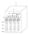
- FIG. 2 is a perspective view showing the configuration of the combustion apparatus according to the first embodiment of the present invention.
- FIG. 3 is an enlarged front view of a gas ring provided in the combustion apparatus according to the first embodiment.
- FIG. 4 is an enlarged vertical sectional view of a first nozzle provided in the combustion apparatus according to the first embodiment.
- FIG. 5 is an enlarged vertical cross-sectional view of the tip of the first nozzle provided in the combustion apparatus according to the first embodiment.
- 6 is a view on arrow X in FIG.
- FIG. 7 is a layout view of the plurality of second nozzles provided in the combustion apparatus according to the first embodiment, and is a state diagram when viewing the plurality of second nozzles from the furnace side.
- the combustion apparatus 6A includes an arc-shaped first gas ring 171.
- the first gas ring 171 forms a cylindrical pipe member in an arc shape.
- the first gas ring 171 is partially interrupted.
- the first gas ring 171 closes its both ends.
- the first gas ring 171 is supplied with ammonia gas from an ammonia gas supply pipe 151 b.
- the first gas ring 171 has a long first nozzle 175 disposed at the center.
- the first nozzle 175 Around the first nozzle 175, five long second nozzles 173A, 173B, 173C, 173D and 173E are disposed. Since these second nozzles 173A, 173B, 173C, 173D, and 173E are the same, the second nozzle 173B may be described as a representative.
- the first gas ring 171 projects five burner nozzles 172A, 172B, 172C, 172D and 172E toward the center. These burner nozzles 172A, 172B, 172C, 172D, 172E are connected to the second nozzles 173A, 173B, 173C, 173D, 173E.
- ammonia gas when ammonia gas is supplied to the first gas ring 171, ammonia gas is supplied from the second injection port 173h provided at the tip of these second nozzles 173A, 173B, 173C, 173D, 173E. Can be injected (see FIG. 5 or FIG. 6).
- the combustion apparatus 6A supplies ammonia gas to the four first gas rings 171 disposed at the uppermost stage of the boiler 6, and the five second nozzles connected to the first gas rings 171 Ammonia gas can be injected from 173A, 173B, 173C, 173D and 173E. That is, ammonia gas can be injected from the one second nozzle 173B toward the inside of the furnace.
- the burner nozzle 172A, 172B, 172C, 172D, 172E is provided with a gas fuel pipe shutoff valve 71B.
- a gas fuel pipe shutoff valve 71B By opening the gas fuel pipe cutoff valve 71B, ammonia gas can be injected from the second injection port 173h (see FIG. 5 or FIG. 6).
- By closing the gas fuel pipe shutoff valve 71B it is possible to stop the injection of the ammonia gas from the second injection port 173h.
- the first nozzle 175 opens the first injection port 175 h at its tip.
- the first injection port 175 h can inject pulverized coal horizontally toward the inside of the furnace of the combustion device 6 ⁇ / b> A.
- the first nozzle 175 holds the heavy fuel oil burner 174 inside.
- the heavy fuel oil burner 174 can inject misty heavy oil or diesel toward the inside of the furnace of the combustion apparatus 6A.
- the pulverized coal injected from the first nozzle 175 can be burned by igniting this heavy oil or light oil. Further, the ammonia gas injected from the second injection port 173 h can be mixedly burned.
- the second nozzle 173 ⁇ / b> B is disposed such that its axial direction is substantially parallel to the first nozzle 175.
- the second injection port 173 h of the second nozzle 173 B has a smaller inner diameter than the inner diameter of the second nozzle 173 B.
- the second injection port 173 h is in the flow direction C0 of ammonia gas flowing inside the second nozzle 173 B (that is, in the injection direction of pulverized coal injected from the first nozzle 175).
- the injection direction C of the ammonia gas is bent and injected with respect to the substantially parallel direction).
- the second injection port 173 h opens along a tangential direction B of a virtual circle whose central axis is the injection direction of the combustion flame of pulverized coal.
- the ammonia gas injected from the second injection port 173 h is injected along the tangential direction B of the imaginary circle whose central axis is the injection direction of the combustion flame of pulverized coal.
- “along the tangential direction B” means that the injection direction C (the angle ⁇ shown in FIG. 6) in which the ammonia gas is actually injected to the tangential direction B is about ⁇ 30 degrees
- Represents a state that falls within the range of Arrows A shown in FIGS. 6 and 7 indicate the direction from the second injection port 173 h toward the center of the first injection port 175 h.
- the injection direction C of the ammonia gas is inclined with respect to the tangential direction B at a predetermined angle ⁇ toward the injection direction side of the combustion flame of pulverized coal.
- the ammonia gas injection direction C follows the tangential direction B and at a predetermined angle ⁇ on the front side of the paper surface in FIG. It is inclined. It is preferable to have an inclination angle ⁇ to the injection direction side of the combustion flame of pulverized coal in the injection direction C of ammonia gas.
- the combustion apparatus 6A burns the pulverized coal so that the flame in which the ammonia is burned is along the tangential direction B of the imaginary circle whose central axis is the injection direction of the combustion flame in which the pulverized coal is burned. Since the fuel is inclined and injected toward the flame injection direction, the combustion time of ammonia can be secured, and the incomplete combustion of ammonia can be suppressed as much as possible.
- the combustion apparatus 6A is a combustion apparatus 6A that co-fires pulverized coal and ammonia in the furnace, and the flame in which the ammonia is burned is a combustion flame of pulverized coal.
- Ammonia is injected from the second nozzles 173A, 173B, 173C, 173D, and 173E along the tangential direction of the imaginary circle whose central axis is the injection direction, so incomplete combustion of ammonia can be minimized by the combustion flame of pulverized coal. , Can be suppressed.
- ammonia is injected from the second nozzles 173A, 173B, 173C, 173D and 173E along the tangential direction of the combustion flame of pulverized coal, so a swirling flow is made around the combustion flame of pulverized coal. It is also possible to form.
- the flame in which ammonia is burned is made to be along the tangential direction of a virtual circle whose center axis is the injection direction of the combustion flame of pulverized coal around the flame in which pulverized coal is burned.
- the ammonia is injected by being inclined to the injection direction side of the combustion flame of the pulverized coal, the incomplete combustion of the ammonia can be suppressed as much as possible by securing the combustion time of the ammonia.
- 6 A of combustion apparatuses by 1st Embodiment can suppress generation
- FIG. 8 is a perspective view showing the configuration of a combustion apparatus according to a second embodiment of the present invention.
- FIG. 9 is an enlarged front view of a gas ring provided in the combustion apparatus according to the second embodiment.
- the combustion device 6 ⁇ / b> B includes an arc-shaped second gas ring 178.
- the second gas ring 178 has a long first nozzle 175 disposed at the center.
- a long second nozzle 173B is disposed around the first nozzle 175.
- long third nozzles 178A, 178C, 178D, 178E are disposed around the first nozzle 175.
- the second gas ring 178 projects five burner nozzles 172A, 172B, 172C, 172D and 172E toward the center.
- the burner nozzle 172B is connected to the second nozzle 173B.
- the burner nozzles 172A, 172C, 172D and 172E are connected to the third nozzles 178A, 178C, 178D and 178E.
- the ammonia gas is supplied to the burner nozzle 172B from the ammonia gas supply pipe 151b.
- the ammonia gas can be injected from the second injection port 173h provided at the tip of the second nozzle 173B (see FIG. 5 or FIG. 6).
- pulverized coal and ammonia can be co-fired inside the furnace.
- the combustion apparatus 6B supplies ammonia gas to the burner nozzles 172B of the four second gas rings 178 disposed at the uppermost stage of the boiler 6, and one second nozzle connected to the burner nozzle 172B.
- Ammonia gas can be injected from 173B. That is, ammonia gas can be injected from the four second nozzles 173B toward the inside of the furnace.
- a gas fuel pipe shutoff valve 71B is provided on the upstream side of the connecting portion of the burner nozzle 172B with the ammonia gas supply pipe 151b.
- the second gas ring 178 connects the gas fuel pipe 170 (see FIG. 1).
- the gas fuel can be supplied to the third nozzles 178A, 178C, 178D, 178E via the burner nozzles 172A, 172C, 172D, 172E.
- gas fuel can be injected toward the inside of a furnace from the tip part of 3rd nozzle 178A, 178C, 178D, and 178E, and gas fuel can be burned.
- the gaseous fuel can also be injected from the second nozzle 173B via the burner nozzle 172B.
- the combustion apparatus 6B according to the second embodiment can also burn gaseous fuel with the topmost burner 62A.
- the first gas ring 171 and the second gas ring 178 are structurally the same, but are distinguished by changing the sign because the flowing combustion is different.
- the second nozzle 173B and the third nozzle 178A, 178C, 178D, 178E are structurally the same, they are distinguished by changing the sign because the flowing combustion is different.
- the combustion apparatus 6A according to the first embodiment injects ammonia gas from all the first nozzles 173A, 173B, 173C, 173D and 173E, while according to the second embodiment.
- the difference is that the combustion device 6B can inject ammonia gas from the specific second nozzle 173B.
- the combustion flame of ammonia injected from the second injection port 173 h follows the tangential direction of the imaginary circle whose central axis is the injection direction of the combustion flame of pulverized coal, and By opening the periphery of the injection hole 175 h at a predetermined inclination angle ⁇ , the combustion time of ammonia can be secured, and the ammonia can be completely burned.
- the second gas ring 178 may be connected to an air supply line (not shown) instead of the gas fuel pipe 170.
- air is injected from the second nozzles 173A, 173B, 173C, 173D and 173E along the tangential direction of the combustion flame of pulverized coal, so the periphery of the combustion flame of pulverized coal It is also possible to form a swirling flow on the
- the ammonia gas injected from the burner nozzle 173B of the second gas ring 178 disposed at the right end (A) of the uppermost stage of the boiler 6 and the third from the right (C) swirls in the clockwise direction R
- the ammonia gas injected from the burner nozzle 178C of the second gas ring 178 disposed at the left end (D) of the uppermost stage of the boiler 6 and the third from the left (B) can swirl in the counterclockwise direction L. Also, this makes it possible to burn the ammonia gas uniformly without deviation.
- the flame in which the ammonia is burned is in the tangential direction B of the imaginary circle whose central axis is the injection direction of the combustion flame in which the pulverized coal is burned. Since the fuel is injected along the injection direction side of the combustion flame of pulverized coal at a predetermined angle ⁇ , the combustion time of the ammonia can be secured, and the incomplete combustion of the ammonia can be suppressed as much as possible.
- Third Embodiment Composition of combustion device
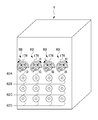
- FIG. 10 is a perspective view showing the configuration of a combustion apparatus according to a third embodiment of the present invention.
- FIG. 11 is an enlarged front view of a third gas ring provided in the combustion apparatus according to the third embodiment.
- FIG. 12 is a layout view of the second nozzle and the fourth nozzle provided in the combustion apparatus according to the third embodiment, in which the second nozzle and the fourth nozzle are viewed from the furnace side.
- the combustion apparatus 6C is disposed on the rightmost side of the topmost burner 62A. Then, in the left three rows of the uppermost stage burner 62A, a combustion device 6D to which ammonia gas is not supplied is disposed. While the combustion device 6C injects ammonia, the combustion device 6D can inject only gas fuel.
- the combustion devices 6C and 6D include a third gas ring 179. Referring to FIG. 11, the third gas ring 179 has a long first nozzle 175 disposed at the center.
- the combustion device 6 ⁇ / b> C arranges a long second nozzle 173 ⁇ / b> B around the first nozzle 175.
- the combustion device 6C has long fourth nozzles 179A, 179C, 179D, 179E arranged around the first nozzle 175.
- the combustion device 6D has long fourth nozzles 179A, 179B, 179C, 179D, 179E arranged around the first nozzle 175.
- the third gas ring 179 of the combustion device 6D protrudes five burner nozzles 172A, 172B, 172C, 172D and 172E toward the central portion.
- the burner nozzle 172B is connected to the second nozzle 173B.
- the burner nozzles 172A, 172C, 172D, 172E are connected to the fourth nozzles 179A, 179C, 179D, 179E.
- the ammonia gas is supplied to the second nozzle 173B from the ammonia gas supply pipe 151b.
- the ammonia gas can be injected from the second injection port 173h provided at the tip of the second nozzle 173B (see FIG. 5 or FIG. 6).
- pulverized coal and ammonia can be co-fired inside the furnace.
- the combustion apparatus 6C supplies ammonia gas to the burner nozzle 172B of one third gas ring 179 disposed at the right end of the uppermost stage of the boiler 6, and connects one burner nozzle 172B to the burner nozzle 172B.
- the ammonia gas can be injected from the two nozzles 173B.
- the third gas ring 179 of the combustion apparatus 6C connects the gas fuel pipe 170 (see FIG. 1).
- the gas fuel can be supplied to the fourth nozzles 179A, 179C, 179D, 179E via the burner nozzles 172A, 172C, 172D, 172E.
- gas fuel can be injected toward the inside of a furnace from the tip part of the 4th nozzle 179A, 179C, 179D, and 179E, and gas fuel can be burned.
- a gas fuel pipe shutoff valve 71B is provided on the upstream side of the connecting portion of the burner nozzle 172B with the ammonia gas supply pipe 151b.
- gaseous fuel can also be injected from the second nozzle 173B via the burner nozzle 172B.
- the combustion apparatus 6C according to the third embodiment can also burn gaseous fuel.
- the first gas ring 171 and the third gas ring 179 are structurally the same, but are distinguished by changing the sign because the flowing combustion is different.
- the second nozzle 173B and the fourth nozzle 179A, 179B, 179C, 179D, 179E are structurally the same, they are distinguished by changing the sign because the circulating combustion is different.
- the ammonia gas supply pipe 151 b is provided with a shutoff valve 54.
- a return pipe 176 branches off upstream of the shutoff valve 54.
- a shutoff valve 177 is provided in the return pipe 176.
- the return pipe 176 is a pipe used when the ammonia gas is not supplied to the burner nozzle 172B from the ammonia gas supply pipe 151b.
- the shutoff valve 54 is closed and the shutoff valve 177 is opened.
- the combustion apparatus 6B by 2nd Embodiment injects ammonia gas from the 2nd nozzle 173B of all the 2nd gas rings 178, but 3rd implementation
- the combustion apparatus 6C according to the embodiment has a difference that the ammonia gas is injected from the second nozzle 173B of the specific third gas ring 179.
- the combustion apparatus 6B and the combustion apparatus 6C are the same, and the second embodiment arranges the four combustion apparatuses 6B, while the third embodiment performs the combustion. There is a difference that only one device 6B is arranged.
- the combustion device 6C is arranged such that the flame in which ammonia is burned is along the tangential direction B of a virtual circle whose central axis is the injection direction of the combustion flame in which pulverized coal is burned and Since the injection is performed with the predetermined angle ⁇ inclined to the injection direction side of the combustion flame of pulverized coal, the combustion time of ammonia can be secured, and the incomplete combustion of ammonia can be suppressed as much as possible.
- the third gas ring 179 may be connected to an air supply line (not shown) instead of the gas fuel pipe 170.
- air is injected from the fourth nozzles 179A, 179C, 179D, 179E along the tangential direction of the combustion flame of pulverized coal, so the swirling flow around the combustion flame of pulverized coal It is also possible to form
- a combustion apparatus 6C is a combustion apparatus 6C for co-firing pulverized coal and ammonia inside a furnace, and a flame in which ammonia is burned causes the pulverized coal to be burned.
- the ammonia is injected at a predetermined angle ⁇ to the injection direction side of the combustion flame of the pulverized coal so that the periphery of the flame is along the tangential direction of the imaginary circle whose central axis is the injection direction of the combustion flame of the pulverized coal Therefore, the incomplete combustion of ammonia can be suppressed as much as possible by securing the combustion time of ammonia.
- the shutoff valve 54 provided in the ammonia gas supply pipe 151 b is opened, and ammonia is closed by closing the gas fuel pipe shutoff valve 71 B provided in the burner nozzle 172 B and the shutoff valve 177 provided in the return pipe 176.
- the gas is supplied to the second nozzle 173B via the ammonia gas supply pipe 151b ⁇ the first connection portion 72 ⁇ the burner nozzle 172B.
- the cross section perpendicular to the length direction of the pulverized coal flame injected from the first nozzle 175 is approximated to a circle, as shown by the arrow in FIG. 12, the second injection port 173h of the second nozzle 173B is , Ammonia is injected in the tangential direction of this circle.
- the ammonia is placed along the tangential direction of the imaginary circle centered on the injection direction of the combustion flame of the pulverized coal around the periphery of the pulverized coal flame and on the injection direction side of the combustion flame of the pulverized coal Since ammonia is injected at a predetermined angle ⁇ , the combustion distance of ammonia is increased, whereby the combustion time of ammonia can be secured and the ammonia can be completely burned.
- FIG. 13 is a graph showing the time-dependent change of the ammonia combustion amount used when the combustion test was performed using the combustion apparatus according to the third embodiment.
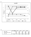
- FIG. 14 is a diagram showing the time change of the amount of used coal when the combustion test was performed using the combustion apparatus according to the third embodiment, and FIG. 14 (a) is a timing of the used amount of coal per unit time The graph which shows change, FIG.14 (b) is a table
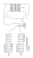
- FIG. 15 is a view showing measurement points at which the ammonia concentration at the outlet of the combustion apparatus is measured using the combustion apparatus according to the third embodiment.
- FIG. 16 is a diagram showing the time change of the NOx value at the outlet of the combustion device using the combustion device according to the third embodiment, and FIG. 16 (a) is a graph showing the time change of the NOx value; b) is a table showing the time change of the NOx value, and FIG. 16 (c) is a table showing the time change of the average output of the power generation facility.
- FIG. 17 is a diagram showing the time change of the CO 2 content in the exhaust gas discharged from the combustion apparatus using the combustion apparatus according to the third embodiment
- FIG. 17 (a) is an ammonia injection per unit time
- FIG.17 (b) is a table which shows the time change of the amount of ammonia injection per unit time, and CO2 content.
- the test period is 7 days, from 13 o'clock to 17 o'clock on the first day, 10 o'clock to 17 o'clock on the second day to the 6th day, and 10 o'clock to 13 o'clock on the 7th day
- a maximum of 450 kg / h of ammonia (note that this is the maximum flow rate of the vaporizer 20 and corresponds to 400 kg of coal) was used.
- the mixed combustion rate of ammonia was about 0.6% (equivalent to 1 MW), but only on the fifth day, the boiler was operated at a load of 120 MW The mixed combustion rate of ammonia was about 0.8%.
- ammonia was burned in the range where there is no excess of exhaust gas.
- liquid ammonia used for combustion has a purity of 99.98%, water content of 0.016%, and an oil content of less than 1.0 ppm, and coal species co-fired with ammonia is 60% for mount oren, and Bocabri premium Is 40%.
- the temperature of metal parts such as piping provided in the boiler 6, that is, the boiler metal temperature was measured at the time of coal-only combustion and at the time of mixed combustion of ammonia and coal.
- the boiler metal temperature at the primary superheater outlet is 400 to 450 ° C.
- the boiler metal temperature at the reheater outlet is 500 to 550 ° C.
- the boiler metal temperature at the secondary superheater inlet is 400 to 450 ° C
- the boiler metal temperature at the middle of the secondary superheater is 450 to 500 ° C
- the boiler metal temperature at the secondary superheater outlet is 500 to 600 ° C.
- the boiler metal temperature at the primary superheater outlet is 400 to 450 ° C
- the boiler metal temperature at the reheater outlet is 500 to 600 ° C
- the boiler metal at the secondary superheater inlet The temperature is 400 to 450 ° C
- the boiler metal temperature in the middle of the secondary superheater is 450 to 550 ° C
- the boiler metal temperature at the outlet of the secondary superheater is 500 to 600 ° C. And there was almost no change.
- FIG. 14 shows the amount of coal used per hour before and after mixed combustion, and the difference between the amounts of coal used.
- the table in FIG. 14 (b) shows the numerical values used in the graph of (a) in the form of a table, and the table in FIG. 14 (c) Indicates the average value of
- the reduction in the amount of used coal after mixed firing compared with that before mixed firing was 0.50 T / h on average for 7 days. That is, 450 kg / h of the amount of ammonia combustion became almost the same as 500 kg / h (anhydrous) of the amount of reduction of coal. Also, comparing the 1st to 7th days, the amount of reduction of coal on the 5th day became the maximum value of 1.96T / h.
- the coal type of coal used for the combustion is 60% of Mount Oen and 40% of Boca-Bri Premium.
- FIG. 16 shows NOx values at the boiler outlet before and after mixed combustion.
- the table of FIG. 16 (b) shows the numerical values used in the graph of FIG. 16 (a) in the form of a table
- the table of FIG. 16 (c) shows the power plant output, mixed combustion rate
- FIG. 16 (c) The average value of the day difference shown in the leftmost column of Further, the value before mixed combustion is a value 30 minutes before the injection of ammonia, and the value after mixed combustion is an average value of data of 4 to 5 points taken every 30 minutes after the injection of ammonia.
- the mixed combustion rate of ammonia is about 0.6% to about 0.8 as compared to other days. It was confirmed that the NOx value at the boiler outlet after co-firing decreased significantly as compared to before co-firing, contrary to the increase to%.
- the mixed burning rate of ammonia was about 0.6%, compared to the mixed burning before mixed burning. While the increase in NOx value after that was not stable, the average value showed a positive value of 0.17 ppm, while the mixed combustion rate of ammonia was about 0.8% on the 5th, before mixed combustion It was confirmed that the amount of increase in NOx value after mixed combustion compared to the above became a negative value of -13.75 ppm.
- the ammonia co-firing rate is desirably 0.8% or more, and it has been suggested that the NOx value can be reduced as the ammonia supply amount is increased. This is, 4NO + 4 NH 3 + O 2 ⁇ 4 N 2 + 6 H 2 O It is presumed that the noncatalytic denitrification reaction has progressed as shown in the chemical reaction formula.
- ammonia is injected in the tangential direction of the pulverized coal flame so that the ammonia draws a spiral locus around the pulverized coal flame, and the combustion time of the ammonia is secured by taking a long combustion distance of the ammonia. It is estimated that
- FIG. 17 shows the output of the boiler, the amount of injected ammonia, and the amount of CO 2 in the exhaust gas from the boiler.
- the table of (b) shows the numerical values used in the graph of (a) in the form of a table.
- the mixed combustion rate of ammonia is 0.6% to 0.8%, so the CO 2 amount is the product of those numerical values, 0. It was predicted to decrease by as little as 1%, but in practice it decreased by 0.2 to 1.3%.
- the annual carbon dioxide reduction amount when the mixed combustion rate is about 0.6% is about 3.99 (thousand t-CO 2 / year), and the annual carbon dioxide reduction when the mixed combustion rate is about 0.8% The amount was about 4.12 (thousand t-CO 2 / year).
- the carbon dioxide emission factor was calculated using the emission factor by electric power company in FY2015 (China Electric Power: 0.0007t-CO2 / kWh) and the facility operation rate as 70%. It is considered that carbon dioxide emissions can be reduced according to the rate of mixed combustion, since all mixed ammonia could be burned in the boiler.
- the combustion apparatus according to the present invention is a combustion apparatus for co-firing pulverized coal and ammonia inside a furnace, and a flame in which ammonia is burned burns pulverized coal around a flame in which pulverized coal is burned.
- Ammonia is injected by tilting to the injection direction side of the combustion flame of pulverized coal so as to be along the tangential direction of a virtual circle whose central axis is the injection direction, so by securing the combustion time of ammonia, incompleteness of ammonia Combustion can be suppressed as much as possible.
- the ammonia is injected in the tangential direction around the pulverized coal flame, and the combustion distance of the ammonia is increased, whereby the combustion time of the ammonia is secured and the ammonia is completely burned.
- the mixed combustion ratio of ammonia injected from the second nozzle to the combustible from the second nozzle is 0.8% or more with respect to pulverized coal injected to the combustion from the first nozzle. And the generation of nitrogen oxides can be suppressed as much as possible.
- the ammonia used for the combustion simultaneously has an effect of denitrifying NOx in the exhaust gas generated by the combustion, so that the ammonia can be effectively used.
Landscapes
- Engineering & Computer Science (AREA)
- Chemical & Material Sciences (AREA)
- Combustion & Propulsion (AREA)
- Mechanical Engineering (AREA)
- General Engineering & Computer Science (AREA)
- Combustion Of Fluid Fuel (AREA)
Abstract
窒素酸化物の発生とアンモニアの不完全燃焼を極力、抑制できる燃焼装置及び燃焼方法を提供する。 燃焼装置6Aは、微粉炭とアンモニアを火炉の内部で混焼できる。燃焼装置6Aは、第1ノズル175と一つ以上の第2ノズル173Bを備える。第1ノズル175は、火炉の内部に向かって微粉炭を噴射する第1噴射口175hを有する。第2ノズル173Bは、第1ノズル175の周囲に配置されている、第2ノズル173Bは、火炉の内部に向かってアンモニアを噴射する第2噴射口173hを有する。第2ノズル173Bの第2噴射口173hは、アンモニアの燃焼火炎が微粉炭の燃焼火炎の噴射方向を中心軸とする仮想円の接線方向に沿うように、かつ、微粉炭の燃焼火炎の噴射方向側に傾斜して開口している。
Description
本発明は、燃焼装置及び燃焼方法に関する。特に、火力発電所などの発電設備などに好適な燃焼装置の構造及び燃焼方法に関する。
火力発電所などは、発電設備としてボイラを設置している。ボイラは、石炭・天然ガス・軽油・重油などの化石燃料をバーナで燃焼させた熱を利用して、高温高圧の蒸気を発生させている。しかし、これらの化石燃料を燃焼させると、二酸化炭素が発生するため、地球温暖化の原因になっている。このため、近年、カーボンクレジット(排出枠)といった形で二酸化炭素を抑制する動きがある。
例えば、LNG(液化天然ガス)は、二酸化炭素の排出量がLPG(液化石油ガス)より少ない。このため、LNGを火力発電所の燃料として使用している。LNGなどのガス燃料は、輸送の際に便宜上、液化が必要である。又、LNGの場合、液化するためにマイナス162度程度の低温状態にする必要があるため、液化が容易ではなく、低温貯蔵の設備のコストも増加するという問題がある。
このようなことから、二酸化炭素を発生しない燃料として、アンモニアガスの利用が提案されている(例えば、特許文献1参照)。アンモニアは、マイナス33度程度で液化すので、例えば、液化にマイナス162度程度必要なLNGと比べて液化が容易であり、設備のコストも安価で済むという利点がある。
又、天然ガスとBOG(boil off gas)の混合ガスと微粉炭とをボイラの内部で混焼可能な同軸バーナを有する多重燃料焚き燃焼装置が開示されている(例えば、特許文献2参照)。
特許文献2による同軸バーナは、微粉炭の火炎をボイラの内部に噴射する内管と、この内管の周囲を囲い、天然ガスとBOGの混合ガスの火炎を微粉炭の火炎の噴射方向と同軸方向に噴射する外管で構成している。
しかし、アンモニアを燃焼させると、アンモニア成分中に含まれる窒素分が酸素と結び付き、窒素酸化物となる懸念がある。
又、アンモニアは燃焼速度が小さく、具体的には、例えばプロパンガスの燃焼速度が40cm/sであるところ、アンモニアの燃焼速度は、8cm/sに過ぎない(このため、アンモニアを燃焼させた場合の火炎は長くなる)。
したがって、アンモニアを他の燃料と混焼させる場合、例えば、特許文献2の図3及び図4に開示したように、同軸バーナを用いて、水平に同軸で噴射して燃焼させると、他の燃料の火炎に対して、アンモニアの火炎が遅延することで、燃焼空間の大小や形状によっては、アンモニアが不完全燃焼してしまう可能性がある。
このようなことから、窒素酸化物の発生とアンモニアの不完全燃焼を極力、抑制できる燃焼装置及び燃焼方法が求められている。そして、以上のことが本発明の課題といってよい。
本発明は、このような課題に鑑みてなされたものであり、窒素酸化物の発生とアンモニアの不完全燃焼を極力、抑制できる燃焼装置及び燃焼方法を提供することを目的とする。
本発明者らは、微粉炭とアンモニアを火炉の内部で混焼する燃焼装置であって、アンモニアを燃焼させた火炎が微粉炭の燃焼火炎の噴射方向を中心軸とする仮想円の接線方向に沿うように、微粉炭の燃焼火炎の噴射方向側に傾斜して噴射することで、窒素酸化物の発生とアンモニアの不完全燃焼を極力、抑制できると考え、これに基づいて、以下のような新たな燃焼装置及び燃焼方法を発明するに至った。
(1)本発明による燃焼装置は、微粉炭とアンモニアを火炉の内部で混焼させる燃焼装置であって、前記火炉の内部に向かって微粉炭を噴射する第1噴射口を有する第1ノズルと、前記第1ノズルの周囲に配置され、前記火炉の内部に向かってアンモニアを噴射する第2噴射口を有する一つ以上の第2ノズルと、を備え、前記第2ノズルの第2噴射口は、アンモニアの燃焼火炎が微粉炭の燃焼火炎の噴射方向を中心軸とする仮想円の接線方向に沿うように、かつ、微粉炭の燃焼火炎の噴射方向側に傾斜して開口している。
(2)本発明による燃焼装置は、アンモニアを前記第2ノズルに向けて輸送するアンモニアガス供給配管と、前記第1ノズルを中心部に配置し、前記アンモニアガス供給配管からアンモニアガスが分配される第1ガスリングと、を備え、前記第2ノズルは、前記第1ノズルの周囲に配置された複数の第2ノズルからなり、これらの前記第2ノズルは、前記第1ガスリングからアンモニアガスが供給されていてもよい。
(3)本発明による燃焼装置は、アンモニアを前記第2ノズルに向けて輸送するアンモニアガス供給配管と、ガス燃料が輸送されるガス燃料配管と、前記第1ノズルを中心部に配置し、前記ガス燃料配管からガス燃料が分配される第2ガスリングと、前記第1ノズルの周囲に配置した単一の前記第2ノズルと、前記第1ノズルの周囲に配置し、前記火炉の内部に向かってガス燃料を噴射する一つ以上の第3ノズルと、前記第2ガスリングと前記第2ノズル及び前記第3ノズルを接続するバーナノズルと、を備え、前記第2ノズルを接続したバーナノズルは、当該バーナノズルの流路を開閉自在なガス燃料配管遮断弁を有し、前記アンモニアガス供給配管は、前記ガス燃料配管遮断弁を閉じた状態で、前記第2噴射口からアンモニアを噴射可能に、前記第2ノズルに接続したバーナノズルに直結していてもよい。
(4)本発明による燃焼方法は、(1)から(3)のいずれかに記載の燃焼装置に用いられ、微粉炭とアンモニアを火炉の内部で混焼させる燃焼方法であって、前記第1ノズルから燃焼可能に噴射される微粉炭に対して、前記第2ノズルから燃焼可能に噴射されるアンモニアの混焼率が、0.8%以上である。
本発明による燃焼装置は、微粉炭とアンモニアを火炉の内部で混焼する燃焼装置であって、アンモニアを燃焼させた火炎が微粉炭を燃焼させた燃焼火炎の噴射方向を中心軸とする仮想円の接線方向に沿うように、かつ、微粉炭の燃焼火炎の噴射方向側に傾斜して噴射するので、アンモニアの燃焼時間を確保でき、アンモニアの不完全燃焼を極力、抑制できる。
本発明による燃焼方法は、第1ノズルから燃焼可能に噴射される微粉炭に対して、第2ノズルから燃焼可能に噴射されるアンモニアの混焼率を0.8%以上とすることで、窒素酸化物の発生を極力、抑制できる。
以下、図面を参照して本発明を実施するための形態を説明する。
[火力発電設備の構成]
最初に、本発明による燃焼装置を備えた火力発電設備の一実施形態による構成を説明する。図1は、本発明による燃焼装置を備えた火力発電設備の一実施形態による構成を示す機能ブロック図である。
[火力発電設備の構成]
最初に、本発明による燃焼装置を備えた火力発電設備の一実施形態による構成を説明する。図1は、本発明による燃焼装置を備えた火力発電設備の一実施形態による構成を示す機能ブロック図である。
図1を参照すると、一実施形態の火力発電設備1は、アンモニアガスを燃焼可能なシステムであるが、微粉炭、油、天然ガス、又は、BOGなどのアンモニアガス以外も燃焼可能である。
図1を参照すると、火力発電設備1は、アンモニアガス供給設備2とアンモニアガス燃料用配管設備3を備えている。又、火力発電設備1は、ボイラ(火炉)6、脱硝設備90、及び、ガス燃料供給部70を備えている。ガス燃料供給部70は、ガス燃料配管170を介して、アンモニアガス以外のガス燃料をボイラ6に供給できる。更に、火力発電設備1は、制御部7を備えている。制御部7は、これら装置の全体を制御している。
(アンモニアガス供給設備の構成)
次に、実施形態によるアンモニアガス供給設備2の構成を説明する。図1を参照すると、アンモニアガス供給設備2は、貯蔵タンク10と気化器20を備えている。又、アンモニアガス供給設備2は、アキュムレータ30とアンモニアガス吸収部80を備えている。なお、アンモニアガス吸収部80は、実態として、水を貯蔵した貯水槽である。アンモニアガス吸収部80は、アンモニアガス供給設備2に設けたブロー弁81から排出されたアンモニアガスを水に吸収できる。
次に、実施形態によるアンモニアガス供給設備2の構成を説明する。図1を参照すると、アンモニアガス供給設備2は、貯蔵タンク10と気化器20を備えている。又、アンモニアガス供給設備2は、アキュムレータ30とアンモニアガス吸収部80を備えている。なお、アンモニアガス吸収部80は、実態として、水を貯蔵した貯水槽である。アンモニアガス吸収部80は、アンモニアガス供給設備2に設けたブロー弁81から排出されたアンモニアガスを水に吸収できる。
(貯蔵タンクの構成)
次に、実施形態による貯蔵タンク10の構成を説明する。図1を参照すると、貯蔵タンク10は、加圧されて液化された液体アンモニアを貯蔵している。貯蔵タンク10は、配管110を介して、気化器20に接続している。配管110は、気化器20に至る途中が二方向に分岐している。分岐された一方の配管110aには、気化器起動弁11及び気化器20内の圧力を制御する気化器圧力調整弁12が上流側から順次配置されている。分岐された他方の配管110bには、気化器バイパス弁13が配置されている。
次に、実施形態による貯蔵タンク10の構成を説明する。図1を参照すると、貯蔵タンク10は、加圧されて液化された液体アンモニアを貯蔵している。貯蔵タンク10は、配管110を介して、気化器20に接続している。配管110は、気化器20に至る途中が二方向に分岐している。分岐された一方の配管110aには、気化器起動弁11及び気化器20内の圧力を制御する気化器圧力調整弁12が上流側から順次配置されている。分岐された他方の配管110bには、気化器バイパス弁13が配置されている。
(気化器の構成)
次に、実施形態による気化器20の構成を説明する。図1を参照すると、気化器20は、貯蔵タンク10から供給される液体アンモニアを加熱して気化させている。気化器20の内部の液体アンモニアは、温水中に浸漬されたコイル状配管内を通って昇温されて気化されることで、アンモニアガスを生成できる。気化器20の下流側は、配管120を介して、アキュムレータ30に接続している。
次に、実施形態による気化器20の構成を説明する。図1を参照すると、気化器20は、貯蔵タンク10から供給される液体アンモニアを加熱して気化させている。気化器20の内部の液体アンモニアは、温水中に浸漬されたコイル状配管内を通って昇温されて気化されることで、アンモニアガスを生成できる。気化器20の下流側は、配管120を介して、アキュムレータ30に接続している。
図1を参照すると、配管120は、アキュムレータ30に至る途中が二方向に分岐している。分岐された一方の配管120aには、アキュムレータ起動弁21、アキュムレータ30内の圧力を制御するアキュムレータ圧力調整弁22が上流側から順次配置している。分岐された他方の配管120bには、アキュムレータバイパス弁23を配置している。
(アキュムレータの構成)
次に、実施形態によるアキュムレータ30の構成を説明する。図1を参照すると、アキュムレータ30は、アンモニアガスを蓄積し、圧力を安定させる装置である。アキュムレータ30の下流側からは配管130が延びている。配管130は、二方向に分岐している。分岐された一方の配管132は、ヘッダー40に接続している。分岐された他方の配管131は、アンモニアガス燃料用配管設備3に接続している。
次に、実施形態によるアキュムレータ30の構成を説明する。図1を参照すると、アキュムレータ30は、アンモニアガスを蓄積し、圧力を安定させる装置である。アキュムレータ30の下流側からは配管130が延びている。配管130は、二方向に分岐している。分岐された一方の配管132は、ヘッダー40に接続している。分岐された他方の配管131は、アンモニアガス燃料用配管設備3に接続している。
(ヘッダーの構成)
次に、実施形態によるヘッダー40の構成を説明する。図1を参照すると、ヘッダー40は、その下流側に配管140を接続している。配管140は、複数の脱硝配管141・142・143に分岐している。これらの脱硝配管141・142・143は、脱硝遮断弁41・42・43を介して、脱硝設備90に接続している。
次に、実施形態によるヘッダー40の構成を説明する。図1を参照すると、ヘッダー40は、その下流側に配管140を接続している。配管140は、複数の脱硝配管141・142・143に分岐している。これらの脱硝配管141・142・143は、脱硝遮断弁41・42・43を介して、脱硝設備90に接続している。
(脱硝設備の構成)
次に、実施形態による脱硝設備90の構成を説明する。図1を参照すると、脱硝設備90は、三つの脱硝装置91・92・93で構成している。脱硝配管141・142・143は、三つの脱硝装置91・92・93にそれぞれ接続している。脱硝配管141・142・143には、燃焼装置6から燃焼で生じた排ガスが送り込まれ、141・142・143の内の脱硝遮断弁41・42・43が開いている配管から流入されたアンモニアガスを還元剤として、排ガス中の窒素酸化物を無害な窒素ガスと水とに転換できる。
次に、実施形態による脱硝設備90の構成を説明する。図1を参照すると、脱硝設備90は、三つの脱硝装置91・92・93で構成している。脱硝配管141・142・143は、三つの脱硝装置91・92・93にそれぞれ接続している。脱硝配管141・142・143には、燃焼装置6から燃焼で生じた排ガスが送り込まれ、141・142・143の内の脱硝遮断弁41・42・43が開いている配管から流入されたアンモニアガスを還元剤として、排ガス中の窒素酸化物を無害な窒素ガスと水とに転換できる。
(アンモニアガス燃料用配管設備の構成)
次に、実施形態によるアンモニアガス燃料用配管設備3の構成を説明する。図1を参照すると、アキュムレータ30から延びる配管130から分岐した配管131は、アンモニアガス燃料用配管設備3に接続している。配管131の上流側は、遮断弁31を設けている。遮断弁31の下流側は、パージ弁36を介して、パージ配管133を接続している。パージ配管133の末端部には、パージ用ガス供給部37を接続している。パージ用ガス供給部37は、窒素ガスなどのパージガスをアンモニアガス燃料用配管設備3に流入できる。
次に、実施形態によるアンモニアガス燃料用配管設備3の構成を説明する。図1を参照すると、アキュムレータ30から延びる配管130から分岐した配管131は、アンモニアガス燃料用配管設備3に接続している。配管131の上流側は、遮断弁31を設けている。遮断弁31の下流側は、パージ弁36を介して、パージ配管133を接続している。パージ配管133の末端部には、パージ用ガス供給部37を接続している。パージ用ガス供給部37は、窒素ガスなどのパージガスをアンモニアガス燃料用配管設備3に流入できる。
図1を参照すると、配管131におけるパージ配管133が接続されている接続部よりも下流側は、二方向に分岐している。分岐された一方の配管131aには、圧力調整弁32を配置している。分岐された他方の配管131bには、遮断弁33を配置している。配管131aと配管131bとは、下流側で再度合流している。合流した配管131は、遮断弁34を介して流量計50に接続している。
図1を参照すると、流量計50は、配管131を流れるガスの流量を測定している。流量計50の下流側からは、配管150が延びている。配管150は、その途中が二方向に分岐している。分岐された一方の配管150aには、流量調整弁51を配置している。分岐された他方の配管150bには、遮断弁52を配置している。配管150aと配管150bとは、下流側で再度合流している。
図1を参照すると、合流した配管150の下流側は、第2接続部56で二方向に分岐している。分岐された一方の配管は、アンモニアガス流出配管151aであり、アンモニア流出遮断弁55を介して、アンモニアガス供給設備2のアンモニアガス吸収部80に接続している。アンモニアガス吸収部80は、上述のように貯水槽であり、アンモニアガスを水に溶解できる。
図1を参照すると、分岐された他方のアンモニアガス供給配管151bには、バーナ弁53を配置している。配管150におけるバーナ弁53の下流側には、冷却空気が流入される冷却配管160が冷却空気弁61を介して、接続されている。なお、アンモニアガス流出配管151aは、バーナ弁53の下流で分岐していてもよい。
図1を参照すると、アンモニアガス供給配管151bの下流側は、遮断弁54を介して、ガス燃料供給部70から、ボイラ6のバーナ62Aまで延びるガス燃料配管170の第1接続部72に接続している。
(ガス燃料供給部の構成)
次に、実施形態によるガス燃料供給部70の構成を説明する。図1を参照すると、ガス燃料供給部70には、LNG(液化天然ガス)を貯蔵している。LNGを液化して貯蔵する場合に、外部からの自然入熱などによりLNGが気化して、BOGガス(boil off gas)が発生する。本実施形態では、ガス燃料配管170は、このBOGを燃料として後述するバーナに輸送する配管である。
次に、実施形態によるガス燃料供給部70の構成を説明する。図1を参照すると、ガス燃料供給部70には、LNG(液化天然ガス)を貯蔵している。LNGを液化して貯蔵する場合に、外部からの自然入熱などによりLNGが気化して、BOGガス(boil off gas)が発生する。本実施形態では、ガス燃料配管170は、このBOGを燃料として後述するバーナに輸送する配管である。
図1を参照すると、ガス燃料配管170は、第1接続部72の下流側において、燃焼装置6のバーナに接続している。ガス燃料配管170における第1接続部72の上流側には、ガス燃料配管遮断弁71を配置している。
図1を参照して、遮断弁54を閉じると共に、ガス燃料配管遮断弁71を開くことで、BOGをバーナ62Aに供給できる。遮断弁54を開くと共に、ガス燃料配管遮断弁71を閉じることで、アンモニアをバーナに供給できる。
(ボイラの構成)
次に、ボイラ6の構成を説明する。図1を参照すると、ボイラ6は、複数のバーナを縦横に配列している。実施形態では、四段のバーナ62A・62B・62C・62Dを高さ方向に配列している。又、これらのバーナは、水平方向に四列に配置している。
次に、ボイラ6の構成を説明する。図1を参照すると、ボイラ6は、複数のバーナを縦横に配列している。実施形態では、四段のバーナ62A・62B・62C・62Dを高さ方向に配列している。又、これらのバーナは、水平方向に四列に配置している。
図1を参照すると、四段のバーナ62A・62B・62C・62Dには、石炭貯蔵部75から燃料としての石炭(微粉炭)が供給されている。最上段の4つのバーナ62Aには、ガス燃料又はアンモニアを供給できる。
図1を参照して、本発明による燃焼装置は、実体として、ボイラ6の最上段に配置される四つのバーナ62Aである。そして、最上段の4つのバーナ62Aの全て又は一部にアンモニアを供給することで、実施形態が異なっている。以下、第1実施形態による燃焼装置を燃焼装置6Aとし、第2実施形態による燃焼装置を燃焼装置6Bとし、第3実施形態による燃焼装置を燃焼装置6Cとして、これらの燃焼装置の構成及び作用を説明する。
[第1実施形態]
(燃焼装置の構成)
次に、第1実施形態による燃焼装置の構成を説明する。なお、第1実施形態による燃焼装置は、図1に開示したガス燃料供給部70を備えていない。
(燃焼装置の構成)
次に、第1実施形態による燃焼装置の構成を説明する。なお、第1実施形態による燃焼装置は、図1に開示したガス燃料供給部70を備えていない。
図2は、本発明の第1実施形態による燃焼装置の構成を示す斜視図である。図3は、第1実施形態による燃焼装置に備わるガスリングを拡大した正面図である。
図4は、第1実施形態による燃焼装置に備わる第1ノズルを拡大した縦断面図である。図5は、第1実施形態による燃焼装置に備わる第1ノズルの先端部を拡大した縦断面図である。図6は、図5のX矢視図である。
図7は、第1実施形態による燃焼装置に備わる複数の第2ノズルの配置図であり、複数の第2ノズルを火炉側から観た状態図である。
図2又は図3を参照すると、第1実施形態による燃焼装置6Aは、円弧状の第1ガスリング171を備えている。第1ガスリング171は、円筒状のパイプ部材を円弧状に形成している。第1ガスリング171は、その一部が中断している。第1ガスリング171は、その両端部を閉塞している。第1ガスリング171は、アンモニアガス供給配管151bからアンモニアガスが供給されている。
図3又は図4を参照すると、第1ガスリング171は、長尺の第1ノズル175を中心部に配置している。第1ノズル175の周囲には、五つの長尺の第2ノズル173A・173B・173C・173D・173Eを配置している。なお、これらの第2ノズル173A・173B・173C・173D・173Eは、同じものであるので、第2ノズル173Bを代表して説明することがある。
図3又は図4を参照すると、第1ガスリング171は、中心部に向かって、五つのバーナノズル172A・172B・172C・172D・172Eを突出している。これらのバーナノズル172A・172B・172C・172D・172Eは、第2ノズル173A・173B・173C・173D・173Eに接続している。
図3又は図4を参照して、第1ガスリング171にアンモニアガスを供給すると、これらの第2ノズル173A・173B・173C・173D・173Eの先端部に設けた第2噴射口173hからアンモニアガスを噴射できる(図5又は図6参照)。
このように、第1実施形態による燃焼装置6Aは、ボイラ6の最上段に配置された四つの第1ガスリング171にアンモニアガスを供給し、第1ガスリング171に接続した五つの第2ノズル173A・173B・173C・173D・173Eからアンモニアガスを噴射できる。つまり、火炉の内部に向かって、一つの第2ノズル173Bからアンモニアガスを噴射できる。
図3を参照すると、バーナノズル172A・172B・172C・172D・172Eには、ガス燃料配管遮断弁71Bをそれぞれ設けている。ガス燃料配管遮断弁71Bを開くことで、第2噴射口173hからアンモニアガスを噴射できる(図5又は図6参照)。ガス燃料配管遮断弁71Bを閉じることで、第2噴射口173hからアンモニアガスの噴射を停止できる。
図4を参照すると、第1ノズル175は、第1噴射口175hを先端部に開口している。第1噴射口175hは、燃焼装置6Aの火炉の内部に向かって水平方向に微粉炭を噴射できる。又、第1ノズル175は、重軽油バーナ174を内部に保持している。重軽油バーナ174は、燃焼装置6Aの火炉の内部に向かって霧状の重油又は軽油を噴射できる。この重油又は軽油を点火することで、第1ノズル175から噴射した微粉炭を燃焼できる。又、第2噴射口173hから噴射したアンモニアガスを混燃できる。
図5を参照すると、第2ノズル173Bは、その軸方向が第1ノズル175と略平行に配置される。第2ノズル173Bの第2噴射口173hは、第2ノズル173Bの内径に比べて、その内径を小さく形成している。これにより、第2ノズル173Bに流れるアンモニアガスを加速して、第2噴射口173hからアンモニアガスを噴射できる。
又、図5又は図6を参照すると、第2噴射口173hは、第2ノズル173Bの内部に流通するアンモニアガスの流通方向C0(つまり、第1ノズル175から噴射される微粉炭の噴射方向に略平行な方向)に対して、アンモニアガスの噴射方向Cを屈曲して噴射している。
より詳細には、図5参照すると、第2噴射口173hは、微粉炭の燃焼火炎の噴射方向を中心軸とする仮想円の接線方向Bに沿うように開口している。これにより、第2噴射口173hから噴射されるアンモニアガスは、微粉炭の燃焼火炎の噴射方向を中心軸とする仮想円の接線方向Bに沿うように噴射される。
尚、本明細書において、「接線方向Bに沿うように」とは、接線方向Bに対して実際にアンモニアガスが噴射される噴射方向C(図6に示す角度θ)が、±30度程度の範囲に収まる状態を表す。
尚、図6及び図7に示す矢印Aは、第2噴射口173hから第1噴射口175hの中心に向かう方向を示す。
尚、本明細書において、「接線方向Bに沿うように」とは、接線方向Bに対して実際にアンモニアガスが噴射される噴射方向C(図6に示す角度θ)が、±30度程度の範囲に収まる状態を表す。
尚、図6及び図7に示す矢印Aは、第2噴射口173hから第1噴射口175hの中心に向かう方向を示す。
又、図5を参照すると、アンモニアガスの噴射方向Cは、接線方向Bに対して微粉炭の燃焼火炎の噴射方向側に所定の角度αで傾斜している。言い換えれば、アンモニアガスの噴射方向Cは、図6に示すように第2ノズル173Bを正面視した場合において接線方向Bに沿うように、かつ、図6における紙面の手前側に所定の角度αに傾斜している。
アンモニアガスの噴射方向Cの、微粉炭の燃焼火炎の噴射方向側への傾斜角度αを持たせることが好ましい。
アンモニアガスの噴射方向Cの、微粉炭の燃焼火炎の噴射方向側への傾斜角度αを持たせることが好ましい。
図7参照すると、燃焼装置6Aは、アンモニアを燃焼させた火炎が微粉炭を燃焼させた燃焼火炎の噴射方向を中心軸とする仮想円の接線方向Bに沿うように、かつ、微粉炭の燃焼火炎の噴射方向側に傾斜して噴射するので、アンモニアの燃焼時間を確保でき、アンモニアの不完全燃焼を極力、抑制できる。
(燃焼装置の作用)
次に、第1実施形態による燃焼装置の作用及び効果を説明する。
次に、第1実施形態による燃焼装置の作用及び効果を説明する。
図2から図7を参照すると、第1実施形態による燃焼装置6Aは、微粉炭とアンモニアを火炉の内部で混焼する燃焼装置6Aであって、アンモニアを燃焼させた火炎が微粉炭の燃焼火炎の噴射方向を中心軸とする仮想円の接線方向に沿うように、第2ノズル173A・173B・173C・173D・173Eからアンモニアを噴射するので、微粉炭の燃焼火炎により、アンモニアの不完全燃焼を極力、抑制できる。
図7を参照すると、第2ノズル173A・173B・173C・173D・173Eから、微粉炭の燃焼火炎の接線方向に沿うように、アンモニアを噴射するので、微粉炭の燃焼火炎の周囲に旋回流を形成することも可能である。
特許文献2の図3及び図4に開示したように、同軸バーナを用いて、水平に同軸で噴射して燃焼させると、他の燃料の火炎に対して、アンモニアの火炎が遅延することで、燃焼空間の大小や形状によっては、アンモニアが不完全燃焼してしまう可能性があった。
第1実施形態による燃焼装置6Aは、アンモニアを燃焼させた火炎が、微粉炭を燃焼させた火炎の周囲を微粉炭の燃焼火炎の噴射方向を中心軸とする仮想円の接線方向に沿うように、かつ、微粉炭の燃焼火炎の噴射方向側に傾斜してアンモニアを噴射するので、アンモニアの燃焼時間を確保することで、アンモニアの不完全燃焼を極力、抑制できる。なお、第1実施形態による燃焼装置6Aは、窒素酸化物の発生を抑制できるが、その実現性については、第3実施形態で説明する。
[第2実施形態]
(燃焼装置の構成)
次に、第2実施形態による燃焼装置の構成を説明する。
(燃焼装置の構成)
次に、第2実施形態による燃焼装置の構成を説明する。
図8は、本発明の第2実施形態による燃焼装置の構成を示す斜視図である。図9は、第2実施形態による燃焼装置に備わるガスリングを拡大した正面図である。
なお、第1実施形態で用いた符号と同じ符号を付した構成品は、その作用を同じにするので、説明を省略することがある。
図8を参照すると、第2実施形態による燃焼装置6Bは、円弧状の第2ガスリング178を備えている。図9を参照すると、第2ガスリング178は、長尺の第1ノズル175を中心部に配置している。第1ノズル175の周囲には、長尺の第2ノズル173Bを配置している。又、第1ノズル175の周囲には、長尺の第3ノズル178A・178C・178D・178Eを配置している。
図9を参照すると、第2ガスリング178は、中心部に向かって、五つのバーナノズル172A・172B・172C・172D・172Eを突出している。バーナノズル172Bは、第2ノズル173Bに接続している。又、バーナノズル172A・172C・172D・172Eは、第3ノズル178A・178C・178D・178Eに接続している。
図9を参照すると、バーナノズル172Bには、アンモニアガス供給配管151bからアンモニアガスが供給されている。バーナノズル172Bにアンモニアガスを供給すると、第2ノズル173Bの先端部に設けた第2噴射口173hからアンモニアガスを噴射できる(図5又は図6参照)。そして、微粉炭とアンモニアを火炉の内部で混焼できる。
このように、第2実施形態による燃焼装置6Bは、ボイラ6の最上段に配置された四つの第2ガスリング178のバーナノズル172Bにアンモニアガスを供給し、バーナノズル172Bに接続した一つの第2ノズル173Bからアンモニアガスを噴射できる。つまり、火炉の内部に向かって、四つの第2ノズル173Bからアンモニアガスを噴射できる。
図9を参照すると、バーナノズル172Bにおけるアンモニアガス供給配管151bとの接続部よりも上流側には、ガス燃料配管遮断弁71Bを設けている。
図9を参照すると、第2ガスリング178は、ガス燃料配管170を接続している(図1参照)。ガス燃料配管遮断弁71Bを閉じた状態では、バーナノズル172A・172C・172D・172Eを介して、第3ノズル178A・178C・178D・178Eにガス燃料を供給できる。そして、第3ノズル178A・178C・178D・178Eの先端部から、火炉の内部に向かってガス燃料を噴射し、ガス燃料を燃焼できる。
図9を参照して、遮断弁54を閉じ、ガス燃料配管遮断弁71Bを開いた状態では、バーナノズル172Bを介して、第2ノズル173Bからガス燃料を噴射することもできる。このように、第2実施形態による燃焼装置6Bは、最上段のバーナ62Aでガス燃料を燃焼することもできる。この場合、最上段のバーナ62Aで微粉炭とガス燃料を火炉の内部で混焼することなく、バーナ62B・62C・62Dで微粉炭を燃焼することが好ましい。
図2から図9を参照して、第1ガスリング171と第2ガスリング178は、構造的に同じものであるが、流通する燃焼が異なることから、符号を変えて区別した。同様に、第2ノズル173Bと第3ノズル178A・178C・178D・178Eは、構造的に同じものであるが、流通する燃焼が異なることから、符号を変えて区別した。
図3と図9を対比すると、第1実施形態による燃焼装置6Aは、全ての第1ノズル173A・173B・173C・173D・173Eからアンモニアガスを噴射しているのに対し、第2実施形態による燃焼装置6Bは、特定の第2ノズル173Bからアンモニアガスを噴射できると、いう違いがある。
図5から図7を参照すると、第2噴射口173hから噴射されるアンモニアの燃焼火炎が、微粉炭の燃焼火炎の噴射方向を中心軸とする仮想円の接線方向に沿うように、かつ、第1噴射口175hの周囲を所定の傾斜角度αで開口していることで、アンモニアの燃焼時間を確保でき、アンモニアを完全燃焼できる。
図9を参照すると、第2ガスリング178には、ガス燃料配管170に換えて、空気の供給ライン(図示せず)に接続することもできる。この場合、図7を参照して、第2ノズル173A・173B・173C・173D・173Eから、微粉炭の燃焼火炎の接線方向に沿うように、空気を噴射するので、微粉炭の燃焼火炎の周囲に旋回流を形成することも可能である。
なお、図8を参照すると、ボイラ6の最上段の右端(A)及び右から3番目(C)に配置された第2ガスリング178のバーナノズル173Bから噴射されるアンモニアガスが時計方向Rに旋回するのに対し、ボイラ6の最上段の左端(D)及び左から3番目(B)に配置された第2ガスリング178のバーナノズル178Cから噴射されるアンモニアガスが反時計方向Lに旋回できる。又、これにより、アンモニアガスを偏ることなく、均一に燃焼することが可能になる。
(燃焼装置の作用)
次に、第2実施形態による燃焼装置の作用及び効果を説明する。
次に、第2実施形態による燃焼装置の作用及び効果を説明する。
図8又は図9を参照すると、第2実施形態による燃焼装置6Bは、アンモニアを燃焼させた火炎が、微粉炭を燃焼させた燃焼火炎の噴射方向を中心軸とする仮想円の接線方向Bに沿うように、かつ、微粉炭の燃焼火炎の噴射方向側に所定角度α傾斜して噴射するので、アンモニアの燃焼時間を確保でき、アンモニアの不完全燃焼を極力、抑制できる。
[第3実施形態]
(燃焼装置の構成)
次に、第3実施形態による燃焼装置の構成を説明する。
[第3実施形態]
(燃焼装置の構成)
次に、第3実施形態による燃焼装置の構成を説明する。
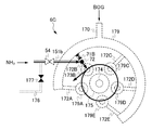
図10は、本発明の第3実施形態による燃焼装置の構成を示す斜視図である。図11は、第3実施形態による燃焼装置に備わる第3ガスリングを拡大した正面図である。図12は、第3実施形態による燃焼装置に備わる第2ノズル及び第4ノズルの配置図であり、第2ノズル及び第4ノズルを火炉側から観た状態図である。
なお、第1実施形態及び第2実施形態で用いた符号と同じ符号を付した構成品は、その作用を同じにするので、説明を省略することがある。
図10又は図11を参照すると、第3実施形態による燃焼装置6Cは、最上段のバーナ62Aの最も右側に配置している。そして、最上段のバーナ62Aの左側3列には、アンモニアガスが供給されない燃焼装置6Dを配置している。燃焼装置6Cがアンモニアを噴射するに対し、燃焼装置6Dは、ガス燃料のみを噴射できる。燃焼装置6C及び6Dは、第3ガスリング179を備えている。図11を参照すると、第3ガスリング179は、長尺の第1ノズル175を中心部に配置している。
図10又は図11を参照すると、燃焼装置6Cは、長尺の第2ノズル173Bを第1ノズル175の周囲に配置している。又、燃焼装置6Cは、長尺の第4ノズル179A・179C・179D・179Eを第1ノズル175の周囲に配置している。燃焼装置6Dは、長尺の第4ノズル179A・179B・179C・179D・179Eを第1ノズル175の周囲に配置している。
図11を参照すると、燃焼装置6Dの第3ガスリング179は、中心部に向かって、五つのバーナノズル172A・172B・172C・172D・172Eを突出している。バーナノズル172Bは、第2ノズル173Bに接続している。又、バーナノズル172A・172C・172D・172Eは、第4ノズル179A・179C・179D・179Eに接続している。
図11を参照すると、第2ノズル173Bには、アンモニアガス供給配管151bからアンモニアガスが供給されている。第2ノズル173Bにアンモニアガスを供給すると、第2ノズル173Bの先端部に設けた第2噴射口173hからアンモニアガスを噴射できる(図5又は図6参照)。そして、微粉炭とアンモニアを火炉の内部で混焼できる。
このように、第3実施形態による燃焼装置6Cは、ボイラ6の最上段の右端に配置された一つの第3ガスリング179のバーナノズル172Bにアンモニアガスを供給し、バーナノズル172Bに接続した一つの第2ノズル173Bからアンモニアガスを噴射できる。
図12を参照すると、燃焼装置6Cの第3ガスリング179は、ガス燃料配管170を接続している(図1参照)。ガス燃料配管遮断弁71Bを閉じた状態では、バーナノズル172A・172C・172D・172Eを介して、第4ノズル179A・179C・179D・179Eにガス燃料を供給できる。そして、第4ノズル179A・179C・179D・179Eの先端部から、火炉の内部に向かってガス燃料を噴射し、ガス燃料を燃焼できる。
図11を参照すると、バーナノズル172Bにおけるアンモニアガス供給配管151bとの接続部よりも上流側には、ガス燃料配管遮断弁71Bを設けている。
図11を参照して、遮断弁54を閉じ、ガス燃料配管遮断弁71Bを開いた状態では、バーナノズル172Bを介して、第2ノズル173Bからガス燃料を噴射することもできる。このように、第3実施形態による燃焼装置6Cは、ガス燃料を燃焼することもできる。この場合、燃焼装置6Cで微粉炭とガス燃料を火炉の内部で混焼することなく、バーナ62A・62B・62C・62Dで微粉炭を燃焼することが好ましい。
図2から図11を参照して、第1ガスリング171と第3ガスリング179は、構造的に同じものであるが、流通する燃焼が異なることから、符号を変えて区別した。同様に、第2ノズル173Bと第4ノズル179A・179B・179C・179D・179Eは、構造的に同じものであるが、流通する燃焼が異なることから、符号を変えて区別した。
図11を参照すると、アンモニアガス供給配管151bには、遮断弁54を設けている。遮断弁54の上流において、戻り配管176が分岐している。戻り配管176には。遮断弁177を設けている。戻り配管176は、アンモニアガス供給配管151bから、アンモニアガスをバーナノズル172Bに供給しない時に用いる配管であり、供給しない場合、遮断弁54を閉じ、遮断弁177を開放する。
図11を参照すると、アンモニアガスをバーナノズル172Bに供給する際は、遮断弁54が開放され、ガス燃料配管遮断弁71Bと遮断弁177が閉じられる。
図8及び図9と図10とを対比すると、第2実施形態による燃焼装置6Bは、全ての第2ガスリング178の第2ノズル173Bからアンモニアガスを噴射しているのに対し、第3実施形態による燃焼装置6Cは、特定の第3ガスリング179の第2ノズル173Bからアンモニアガスを噴射しているという違いがある。
図8と図10を対比すると、燃焼装置6Bと燃焼装置6Cとは同じものであり、第2実施形態は、燃焼装置6Bを四基配列しているのに対し、第3実施形態は、燃焼装置6Bを一基のみ配列しているという違いがある。
図5から図7を参照すると、燃焼装置6Cは、アンモニアを燃焼させた火炎が微粉炭を燃焼させた燃焼火炎の噴射方向を中心軸とする仮想円の接線方向Bに沿うように、かつ、微粉炭の燃焼火炎の噴射方向側に所定角度α傾斜して噴射するので、アンモニアの燃焼時間を確保でき、アンモニアの不完全燃焼を極力、抑制できる。
図11を参照すると、第3ガスリング179には、ガス燃料配管170に換えて、空気の供給ライン(図示せず)に接続することもできる。この場合、図7を援用すると、第4ノズル179A・179C・179D・179Eから、微粉炭の燃焼火炎の接線方向に沿うように、空気を噴射するので、微粉炭の燃焼火炎の周囲に旋回流を形成することも可能である。
(燃焼装置の作用)
次に、第3実施形態による燃焼装置の作用及び効果を説明する。
次に、第3実施形態による燃焼装置の作用及び効果を説明する。
図10から図12を参照すると、第3実施形態による燃焼装置6Cは、微粉炭とアンモニアを火炉の内部で混焼する燃焼装置6Cであって、アンモニアを燃焼させた火炎が、微粉炭を燃焼させた火炎の周囲を微粉炭の燃焼火炎の噴射方向を中心軸とする仮想円の接線方向に沿うように、かつ、微粉炭の燃焼火炎の噴射方向側に所定角度α傾斜してアンモニアを噴射するので、アンモニアの燃焼時間を確保することで、アンモニアの不完全燃焼を極力、抑制できる。
図12を参照すると、アンモニアガス供給配管151bに設けた遮断弁54が開放され、バーナノズル172Bに設けたガス燃料配管遮断弁71Bと、戻り配管176に設けた遮断弁177とを閉じることにより、アンモニアガスは、アンモニアガス供給配管151b→第1接続部72→バーナノズル172Bを経由し、第2ノズル173Bに供給される。更に、第1ノズル175から噴射される微粉炭火炎の長さ方向に対して垂直な断面を円に近似した場合、図12の矢印に示すように、第2ノズル173Bの第2噴射口173hは、この円の接線方向にアンモニアを噴射する。
図12を参照して、アンモニアが微粉炭火炎の周囲を微粉炭の燃焼火炎の噴射方向を中心軸とする仮想円の接線方向に沿うように、かつ、微粉炭の燃焼火炎の噴射方向側に所定角度α傾斜してアンモニアを噴射するので、アンモニアの燃焼距離が長くなることにより、アンモニアの燃焼時間が確保され、アンモニアが完全燃焼されることが可能となる。
〔燃焼試験〕
次に、第3実施形態による燃焼装置6Cを用いた、燃焼試験の結果を説明する。図13は、第3実施形態による燃焼装置を用いて、燃焼試験したときに用いたアンモニア燃焼量の計時変化を示すグラフである。
次に、第3実施形態による燃焼装置6Cを用いた、燃焼試験の結果を説明する。図13は、第3実施形態による燃焼装置を用いて、燃焼試験したときに用いたアンモニア燃焼量の計時変化を示すグラフである。
図14は、第3実施形態による燃焼装置を用いて、燃焼試験したときに用いた石炭使用量の計時変化を示す図であり、図14(a)は、単位時間当たりの石炭使用量の計時変化を示すグラフ、図14(b)は、単位時間当たりの石炭使用量の計時変化を示す表、図14(c)は、発電設備の平均出力の計時変化を示す表である。
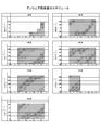
図15は、第3実施形態による燃焼装置を用いて、燃焼装置の出口のアンモニア濃度を計測した計測点を示す図である。
図16は、第3実施形態による燃焼装置を用いて、燃焼装置の出口のNOx値の計時変化を示す図であり、図16(a)は、NOx値の計時変化を示すグラフ、図16(b)は、NOx値の計時変化を示す表、図16(c)は、発電設備の平均出力の計時変化を示す表である。
図17は、第3実施形態による燃焼装置を用いて、燃焼装置から排出される排気ガス中のCO2含有量の計時変化を示す図であり、図17(a)は、単位時間当たりのアンモニア注入量とCO2含有量の計時変化を示すグラフ、図17(b)は、単位時間当たりのアンモニア注入量とCO2含有量の計時変化を示す表である。
図1で開示した火力発電設備1において、以下のアンモニア混焼による燃焼試験を行った。
図13に示すように試験期間は7日間とし、1日目の13時から17時まで、2日目~6日目の10時から17時まで、及び7日目の10時から13時までにおいて、最大450kg/hのアンモニア(なお、これは気化器20の最大流量であり、石炭400kgに相当する)を使用した。
より詳細には、1日目の13時~15時においては100kg/hのアンモニアを燃焼し、1日目の15時~16時においては200kg/hのアンモニアを燃焼し、1日目の16時~17時においては400kg/hのアンモニアを燃焼し、2日目以降は450kg/hのアンモニアを燃焼した。
又、基本的には、ボイラを155MWの負荷で運転したため、アンモニアの混焼率は約0.6%(1MW相当)であったが、5日目のみにおいては、ボイラを120MWの負荷で運転したため、アンモニアの混焼率は約0.8%であった。なお、排ガス量超過がない範囲でアンモニアを燃焼した。
又、燃焼に用いた液体アンモニアは、純度99.98%、水分0.016%、油分が1.0ppm未満であり、アンモニアと混焼した石炭の炭種は、マウントオーエンが60%、ボカブライプレミアムが40%である。
(ボイラメタル温度)
図15を参照して、ボイラ6内に設けられた配管などの金属部分の温度、すなわちボイラメタル温度を、石炭専焼時と、アンモニアと石炭の混焼時とにおいて測定した。測定箇所は、1次過熱器出口、再熱器出口、2次過熱器入口、2次過熱器中間、2次過熱器出口の6箇所である。
図15を参照して、ボイラ6内に設けられた配管などの金属部分の温度、すなわちボイラメタル温度を、石炭専焼時と、アンモニアと石炭の混焼時とにおいて測定した。測定箇所は、1次過熱器出口、再熱器出口、2次過熱器入口、2次過熱器中間、2次過熱器出口の6箇所である。
図15を参照して、測定の結果、ボイラの負荷が155MWの場合には、1次過熱器出口のボイラメタル温度は400~450℃、再熱器出口のボイラメタル温度は500~550℃、2次過熱器入口のボイラメタル温度は400~450℃、2次過熱器中間のボイラメタル温度は450~500℃、2次過熱器出口のボイラメタル温度は500~600℃であり、石炭専焼時と、アンモニアと石炭の混焼時とでは、ほぼ変化がなかった。
同様に、ボイラの負荷が120MWの場合には、1次過熱器出口のボイラメタル温度は400~450℃、再熱器出口のボイラメタル温度は500~600℃、2次過熱器入口のボイラメタル温度は400~450℃、2次過熱器中間のボイラメタル温度は450~550℃、2次過熱器出口のボイラメタル温度は500~600℃であり、石炭専焼時と、アンモニアと石炭の混焼時とでは、ほぼ変化がなかった。
すなわち、ボイラ6内の温度分布に、アンモニアを石炭と混焼した影響は、ほぼ見られなかった。
(石炭量評価〕
図14は、混焼前と混焼後の1時間当たりの石炭使用量、及び、双方の石炭使用量の差を示す。なお、図14(b)の表は、(a)のグラフで用いた数値を表形式で示し、図14(c)の表は、図14(c)内の最も左の列で示される日にちの平均値を示す。
図14は、混焼前と混焼後の1時間当たりの石炭使用量、及び、双方の石炭使用量の差を示す。なお、図14(b)の表は、(a)のグラフで用いた数値を表形式で示し、図14(c)の表は、図14(c)内の最も左の列で示される日にちの平均値を示す。
図14を参照すると、混焼前に比較した混焼後の石炭使用量の減少分は、7日間の平均で、0.50T/hとなった。すなわち、アンモニア燃焼量の450kg/hは、石炭減少量の500kg/h(無水)とほぼ同じとなった。また、1~7日目を比較すると、5日目の石炭減少量が、最大値の1.96T/hとなった。なお、上記の繰り返しとなるが、燃焼に用いた石炭の炭種は、マウントオーエン60%、ボカブライプレミアム40%である。
(ボイラ出口NOx値)
図15を参照して、[A系]及び[B系]で示される断面図中の十字で示されるような、ボイラ出口のA系24点、B系24点の合計48点において、ECO(節炭器)出口ガスのNOx値を測定した。
図15を参照して、[A系]及び[B系]で示される断面図中の十字で示されるような、ボイラ出口のA系24点、B系24点の合計48点において、ECO(節炭器)出口ガスのNOx値を測定した。
図16は、混焼前と混焼後のボイラ出口におけるNOx値を示す。なお、1日目においては種々の機器の調整を実行し、3日目においてはNOx計の点検をしたために、データから除外している。又、図16(b)の表は、図16(a)のグラフで用いた数値を表形式で示し、図16(c)の表は、発電所出力、混焼率、及び図16(c)内の最も左の列で示される日にちの差の平均値を示す。また、混焼前の値は、アンモニア注入前30分の値であり、混焼後の値は、アンモニア注入後30分ごとに4点乃至5点のデータを取った、その平均値である。
図16(c)を参照して、アンモニアの混焼率が約0.8%の5日目においては、他の日に比較して、アンモニアの混焼率が約0.6%から約0.8%に上昇したのに反して、混焼後のボイラ出口におけるNOx値が、混焼前より大きく減少することを確認した。
又、図16(c)を参照して、アンモニアの混焼率が約0.6%であった、2日目、4日目、6日目、7日目においては、混焼前に比較した混焼後のNOx値の増加量は安定しないと共に、その平均値は、0.17ppmとプラスの値を示した一方で、アンモニアの混焼率が約0.8%であった5日目の、混焼前に比較した混焼後のNOx値の増加量は、-13.75ppmとマイナスの値となったことを確認した。
これにより、アンモニアを石炭と混焼させる場合、アンモニア混焼率は0.8%以上が望ましく、又、アンモニア供給量を増加させるほど、NOx値を低減できる可能性が示唆された。
これは、
4NO+4NH3+O2→4N2+6H2O
の化学反応式で示されるような、無触媒脱硝反応が進行したためであると推定される。
これは、
4NO+4NH3+O2→4N2+6H2O
の化学反応式で示されるような、無触媒脱硝反応が進行したためであると推定される。
(ボイラ出口アンモニア濃度)
図15を参照すると、ボイラ出口の合計10点において、ECO(節炭器)出口ガスのアンモニア濃度を測定した所、燃料へのアンモニア注入前のアンモニア濃度は0.3ppmであり、燃料へのアンモニア注入後のアンモニア濃度は0.1~0.4ppmであった。すなわち、燃料へのアンモニア注入後においても、ボイラ出口にはアンモニアはほとんど残留しておらず、アンモニアは完全燃焼していることが確認された。
図15を参照すると、ボイラ出口の合計10点において、ECO(節炭器)出口ガスのアンモニア濃度を測定した所、燃料へのアンモニア注入前のアンモニア濃度は0.3ppmであり、燃料へのアンモニア注入後のアンモニア濃度は0.1~0.4ppmであった。すなわち、燃料へのアンモニア注入後においても、ボイラ出口にはアンモニアはほとんど残留しておらず、アンモニアは完全燃焼していることが確認された。
これは、アンモニアが微粉炭火炎の周囲を螺旋状の軌跡を描くよう、アンモニアを微粉炭火炎の接線方向に噴射し、アンモニアの燃焼距離を長く取ったことにより、アンモニアの燃焼時間が確保されたためであると推定される。
(CO2分析)
図15を参照すると、ボイラの出口2点において、ボイラからの排気ガスの組成を測定した。図17は、ボイラの出力、アンモニア注入量と、ボイラからの排気ガス中のCO2量を示す。なお、(b)の表は、(a)のグラフで用いた数値を表形式で示す。
図15を参照すると、ボイラの出口2点において、ボイラからの排気ガスの組成を測定した。図17は、ボイラの出力、アンモニア注入量と、ボイラからの排気ガス中のCO2量を示す。なお、(b)の表は、(a)のグラフで用いた数値を表形式で示す。
図17を参照すると、当初のCO2量が12.8%である所、アンモニアの混焼率は、0.6%~0.8%であるため、CO2量はそれらの数値の積である0.1%程度しか減少しないことが予測されたが、実際には、0.2~1.3%減少した。
又、混焼率が約0.6%の場合における年間二酸化炭素削減量は、約3.99(千t-CO2/年)であり、混焼率が約0.8%の場合における年間二酸化炭素削減量は、約4.12(千t-CO2/年)であった。(なお、算定にあたっては、二酸化炭素排出係数は、平成27年度の電気事業者別排出係数(中国電力:0.0007t-CO2/kWh)を使用し、設備稼働率は70%として算出した。)混焼したアンモニアがボイラ内で全て燃焼できたため、混焼した率に応じて、二酸化炭素排出量が削減できたものと考えられる。
以上、本実施形態によると以下の効果を有する。
(1)本発明による燃焼装置は、微粉炭とアンモニアを火炉の内部で混焼する燃焼装置であって、アンモニアを燃焼させた火炎が微粉炭を燃焼させた火炎の周囲を微粉炭の燃焼火炎の噴射方向を中心軸とする仮想円の接線方向に沿うように、微粉炭の燃焼火炎の噴射方向側に傾斜してアンモニアを噴射するので、アンモニアの燃焼時間を確保することで、アンモニアの不完全燃焼を極力、抑制できる。
(1)本発明による燃焼装置は、微粉炭とアンモニアを火炉の内部で混焼する燃焼装置であって、アンモニアを燃焼させた火炎が微粉炭を燃焼させた火炎の周囲を微粉炭の燃焼火炎の噴射方向を中心軸とする仮想円の接線方向に沿うように、微粉炭の燃焼火炎の噴射方向側に傾斜してアンモニアを噴射するので、アンモニアの燃焼時間を確保することで、アンモニアの不完全燃焼を極力、抑制できる。
本実施形態によると、アンモニアが微粉炭火炎の周囲を接線方向に噴射され、アンモニアの燃焼距離が長くなることにより、アンモニアの燃焼時間が確保され、アンモニアが完全燃焼される。
(2)本発明による燃焼方法は、第1ノズルから燃焼可能に噴射される微粉炭に対して、第2ノズルから燃焼可能に噴射されるアンモニアの混焼率を0.8%以上とすることで、窒素酸化物の発生を極力、抑制できる。
本実施形態によると、燃焼に用いたアンモニアが、同時に、燃焼により発生する排気ガス中のNOxを脱硝する作用を有することにより、アンモニアを有効活用することが可能となる。
1 火力発電設備
2 アンモニアガス供給設備
3 アンモニアガス燃料用配管設備
6 ボイラ(火炉)
6A・6B・6C・6D バーナ(燃焼装置)
7 制御部
10 貯蔵タンク
11 気化器起動弁
12 気化器圧力調整弁
13 気化器バイパス弁
20 気化器
21 アキュムレータ起動弁
22 アキュムレータ圧力調整弁
23 アキュムレータバイパス弁
30 アキュムレータ
31、33、34、52、54 遮断弁
32 圧力調整弁
36 パージ弁
37 パージ用ガス供給部
40 ヘッダー
50 流量計
51 流量調整弁
53 バーナ弁
54 遮断弁
55 アンモニア流出遮断弁
60A バーナ
61 冷却空気弁
62 バーナ
62A、62B、62C、62D ガスバーナ
70 ガス燃料供給部
71、71B ガス燃料配管遮断弁
72 第1接続部
80 アンモニアガス吸収部
90 脱硝設備
110、110a、110b、120、120a、120b、130、131、131a、131b、132、140、150、150a、150b 配管
133 パージ配管
151a アンモニアガス流出配管
151b アンモニア供給配管
160 冷却配管
170 ガス燃料配管
171 第1ガスリング
172、172A、172B、172C、172D、172E バーナノズル
173A~173E 第2ノズル
173h 第2噴射口
174 重軽油バーナ
175 第1ノズル
175h 第1噴射口
176 戻り配管
177 遮断弁
178 第2ガスリング
178A・178C・178D・178E 第3ノズル
179 第3ガスリング
179A・179B・179C・179D・179E 第4ノズル
2 アンモニアガス供給設備
3 アンモニアガス燃料用配管設備
6 ボイラ(火炉)
6A・6B・6C・6D バーナ(燃焼装置)
7 制御部
10 貯蔵タンク
11 気化器起動弁
12 気化器圧力調整弁
13 気化器バイパス弁
20 気化器
21 アキュムレータ起動弁
22 アキュムレータ圧力調整弁
23 アキュムレータバイパス弁
30 アキュムレータ
31、33、34、52、54 遮断弁
32 圧力調整弁
36 パージ弁
37 パージ用ガス供給部
40 ヘッダー
50 流量計
51 流量調整弁
53 バーナ弁
54 遮断弁
55 アンモニア流出遮断弁
60A バーナ
61 冷却空気弁
62 バーナ
62A、62B、62C、62D ガスバーナ
70 ガス燃料供給部
71、71B ガス燃料配管遮断弁
72 第1接続部
80 アンモニアガス吸収部
90 脱硝設備
110、110a、110b、120、120a、120b、130、131、131a、131b、132、140、150、150a、150b 配管
133 パージ配管
151a アンモニアガス流出配管
151b アンモニア供給配管
160 冷却配管
170 ガス燃料配管
171 第1ガスリング
172、172A、172B、172C、172D、172E バーナノズル
173A~173E 第2ノズル
173h 第2噴射口
174 重軽油バーナ
175 第1ノズル
175h 第1噴射口
176 戻り配管
177 遮断弁
178 第2ガスリング
178A・178C・178D・178E 第3ノズル
179 第3ガスリング
179A・179B・179C・179D・179E 第4ノズル
Claims (4)
- 微粉炭とアンモニアを火炉の内部で混焼させる燃焼装置であって、
前記火炉の内部に向かって微粉炭を噴射する第1噴射口を有する第1ノズルと、
前記第1ノズルの周囲に配置され、前記火炉の内部に向かってアンモニアを噴射する第2噴射口を有する一つ以上の第2ノズルと、を備え、
前記第2ノズルの第2噴射口は、アンモニアの燃焼火炎が微粉炭の燃焼火炎の噴射方向を中心軸とする仮想円の接線方向に沿うように、かつ、微粉炭の燃焼火炎の噴射方向側に傾斜して開口している、燃焼装置。 - アンモニアを前記第2ノズルに向けて輸送するアンモニアガス供給配管と、
前記第1ノズルを中心部に配置し、前記アンモニアガス供給配管からアンモニアガスが分配される第1ガスリングと、を備え、
前記第2ノズルは、前記第1ノズルの周囲に配置された複数の第2ノズルからなり、
これらの前記第2ノズルは、前記第1ガスリングからアンモニアガスが供給されている、請求項1記載の燃焼装置。 - アンモニアを前記第2ノズルに向けて輸送するアンモニアガス供給配管と、
ガス燃料が輸送されるガス燃料配管と、
前記第1ノズルを中心部に配置し、前記ガス燃料配管からガス燃料が分配される第2ガスリングと、
前記第1ノズルの周囲に配置した単一の前記第2ノズルと、
前記第1ノズルの周囲に配置し、前記火炉の内部に向かってガス燃料を噴射する一つ以上の第3ノズルと、
前記第2ガスリングと前記第2ノズル及び前記第3ノズルを接続するバーナノズルと、を備え、
前記第2ノズルを接続したバーナノズルは、当該バーナノズルの流路を開閉自在なガス燃料配管遮断弁を有し、
前記アンモニアガス供給配管は、前記ガス燃料配管遮断弁を閉じた状態で、前記第2噴射口からアンモニアを噴射可能に、前記第2ノズルに接続したバーナノズルに直結している、請求項1記載の燃焼装置。 - 請求項1から3のいずれかに記載の燃焼装置に用いられ、微粉炭とアンモニアを火炉の内部で混焼させる燃焼方法であって、
前記第1ノズルから燃焼可能に噴射される微粉炭に対して、前記第2ノズルから燃焼可能に噴射されるアンモニアの混焼率が、0.8%以上である、燃焼方法。
Priority Applications (2)
| Application Number | Priority Date | Filing Date | Title |
|---|---|---|---|
| PCT/JP2017/034586 WO2019058563A1 (ja) | 2017-09-25 | 2017-09-25 | 燃焼装置及び燃焼方法 |
| JP2017566437A JP6296216B1 (ja) | 2017-09-25 | 2017-09-25 | 燃焼装置及び燃焼方法 |
Applications Claiming Priority (1)
| Application Number | Priority Date | Filing Date | Title |
|---|---|---|---|
| PCT/JP2017/034586 WO2019058563A1 (ja) | 2017-09-25 | 2017-09-25 | 燃焼装置及び燃焼方法 |
Publications (1)
| Publication Number | Publication Date |
|---|---|
| WO2019058563A1 true WO2019058563A1 (ja) | 2019-03-28 |
Family
ID=61629189
Family Applications (1)
| Application Number | Title | Priority Date | Filing Date |
|---|---|---|---|
| PCT/JP2017/034586 Ceased WO2019058563A1 (ja) | 2017-09-25 | 2017-09-25 | 燃焼装置及び燃焼方法 |
Country Status (2)
| Country | Link |
|---|---|
| JP (1) | JP6296216B1 (ja) |
| WO (1) | WO2019058563A1 (ja) |
Cited By (4)
| Publication number | Priority date | Publication date | Assignee | Title |
|---|---|---|---|---|
| KR20210098795A (ko) | 2020-02-03 | 2021-08-11 | 에이치에스디엔진 주식회사 | 버너장치 및 이를 포함하는 선박 |
| CN114893767A (zh) * | 2022-05-10 | 2022-08-12 | 华中科技大学 | 一种带有折流结构的掺氨旋流燃烧器 |
| CN115949936A (zh) * | 2022-11-01 | 2023-04-11 | 天津大学 | 一种喷水加氢的超低氮氨煤混烧气固相两相燃烧器 |
| JP2024085821A (ja) * | 2022-12-15 | 2024-06-27 | 三建産業株式会社 | アンモニア燃焼バーナ |
Families Citing this family (6)
| Publication number | Priority date | Publication date | Assignee | Title |
|---|---|---|---|---|
| JP7039782B2 (ja) * | 2018-03-30 | 2022-03-23 | 三菱重工業株式会社 | 火力発電プラント、混焼ボイラ及びボイラの改造方法 |
| JP6813533B2 (ja) * | 2018-05-22 | 2021-01-13 | 三菱パワー株式会社 | バーナおよび燃焼装置 |
| JP7485500B2 (ja) * | 2018-09-11 | 2024-05-16 | 株式会社Ihi | 燃焼装置及びボイラ |
| JP7081407B2 (ja) * | 2018-09-11 | 2022-06-07 | 株式会社Ihi | ボイラ |
| JP7205299B2 (ja) * | 2019-02-28 | 2023-01-17 | 株式会社Ihi | 燃焼器 |
| JP7583598B2 (ja) * | 2020-12-09 | 2024-11-14 | 川崎重工業株式会社 | 燃料燃焼システム |
Citations (5)
| Publication number | Priority date | Publication date | Assignee | Title |
|---|---|---|---|---|
| JPS58187709A (ja) * | 1982-04-26 | 1983-11-02 | Hitachi Ltd | 石炭中窒素利用微粉炭燃焼方式 |
| JPS62909U (ja) * | 1985-06-17 | 1987-01-07 | ||
| JP2016041990A (ja) * | 2014-08-18 | 2016-03-31 | 東洋エンジニアリング株式会社 | ボイラーを含む発熱装置 |
| JP2016183840A (ja) * | 2015-03-26 | 2016-10-20 | 一般財団法人電力中央研究所 | 発電設備 |
| JP2016183839A (ja) * | 2015-03-26 | 2016-10-20 | 一般財団法人電力中央研究所 | 微粉炭焚きボイラ装置及び発電設備 |
-
2017
- 2017-09-25 WO PCT/JP2017/034586 patent/WO2019058563A1/ja not_active Ceased
- 2017-09-25 JP JP2017566437A patent/JP6296216B1/ja active Active
Patent Citations (5)
| Publication number | Priority date | Publication date | Assignee | Title |
|---|---|---|---|---|
| JPS58187709A (ja) * | 1982-04-26 | 1983-11-02 | Hitachi Ltd | 石炭中窒素利用微粉炭燃焼方式 |
| JPS62909U (ja) * | 1985-06-17 | 1987-01-07 | ||
| JP2016041990A (ja) * | 2014-08-18 | 2016-03-31 | 東洋エンジニアリング株式会社 | ボイラーを含む発熱装置 |
| JP2016183840A (ja) * | 2015-03-26 | 2016-10-20 | 一般財団法人電力中央研究所 | 発電設備 |
| JP2016183839A (ja) * | 2015-03-26 | 2016-10-20 | 一般財団法人電力中央研究所 | 微粉炭焚きボイラ装置及び発電設備 |
Cited By (7)
| Publication number | Priority date | Publication date | Assignee | Title |
|---|---|---|---|---|
| KR20210098795A (ko) | 2020-02-03 | 2021-08-11 | 에이치에스디엔진 주식회사 | 버너장치 및 이를 포함하는 선박 |
| KR102402336B1 (ko) * | 2020-02-03 | 2022-05-27 | 에이치에스디엔진 주식회사 | 버너장치 및 이를 포함하는 선박 |
| CN114893767A (zh) * | 2022-05-10 | 2022-08-12 | 华中科技大学 | 一种带有折流结构的掺氨旋流燃烧器 |
| CN114893767B (zh) * | 2022-05-10 | 2023-03-10 | 华中科技大学 | 一种带有折流结构的掺氨旋流燃烧器 |
| CN115949936A (zh) * | 2022-11-01 | 2023-04-11 | 天津大学 | 一种喷水加氢的超低氮氨煤混烧气固相两相燃烧器 |
| JP2024085821A (ja) * | 2022-12-15 | 2024-06-27 | 三建産業株式会社 | アンモニア燃焼バーナ |
| JP7727939B2 (ja) | 2022-12-15 | 2025-08-22 | 三建産業株式会社 | アンモニア燃焼バーナ |
Also Published As
| Publication number | Publication date |
|---|---|
| JPWO2019058563A1 (ja) | 2019-11-14 |
| JP6296216B1 (ja) | 2018-03-20 |
Similar Documents
| Publication | Publication Date | Title |
|---|---|---|
| JP6296216B1 (ja) | 燃焼装置及び燃焼方法 | |
| Tamura et al. | Experimental investigation of ammonia combustion in a bench scale 1.2 MW-thermal pulverised coal firing furnace | |
| Lee et al. | Industrial gas turbine combustion performance test of DME to use as an alternative fuel for power generation | |
| JP6332578B1 (ja) | 燃焼方法 | |
| CN1769655B (zh) | 燃气轮机发电设备 | |
| JP5063538B2 (ja) | ガスタービンの燃料供給方法 | |
| JP7723492B2 (ja) | ボイラの運転方法、及び、ボイラ用の制御装置 | |
| US20090280442A1 (en) | Device And Method Of Combusting Solid Fuel With Oxygen | |
| US20260110429A1 (en) | Burner, System, and Method for Hydrogen-Enhanced Pulverized Coal Ignition | |
| JP6319526B1 (ja) | 発電設備 | |
| JP6304462B1 (ja) | 発電設備 | |
| JP6357701B1 (ja) | 燃焼状態判定システム | |
| CN118623308A (zh) | 一种适用于多种燃料混烧的燃烧器 | |
| Lu et al. | A combustion strategy for multi-emission control via secondary ammonia injection in a swirl combustor | |
| JP7150102B1 (ja) | 二段燃焼装置 | |
| Elkady et al. | Exhaust gas recirculation performance in dry low emissions combustors | |
| EP2472179A1 (en) | Burner assembly, gas turbine power plant comprising said burner assembly, and method for operating said burner assembly | |
| Do¨ bbeling et al. | 25 years of bbc/abb/alstom lean premix combustion technologies | |
| JP7262521B2 (ja) | ガスバーナ、及び燃焼設備 | |
| JP7680916B2 (ja) | 燃焼装置およびボイラ | |
| Anggono et al. | Effects of Ammonia on the Flame Characteristics of Liquefied Petroleum Gas External Premixed Combustion | |
| JP2025005036A (ja) | 予混合装置及びボイラ並びにボイラの改造方法 | |
| BR112024024823B1 (pt) | Queimador para uma câmara de combustão, caldeira, método para gerar uma chama em uma câmara de combustão de um dispositivo de combustão | |
| JP6644569B2 (ja) | ボイラ及びこれを備えた浮体設備 | |
| ElKady et al. | Application of exhaust gas recirculation for post combustion CO2 capture: Effect on lean premixed combustion |
Legal Events
| Date | Code | Title | Description |
|---|---|---|---|
| ENP | Entry into the national phase |
Ref document number: 2017566437 Country of ref document: JP Kind code of ref document: A |
|
| 121 | Ep: the epo has been informed by wipo that ep was designated in this application |
Ref document number: 17926205 Country of ref document: EP Kind code of ref document: A1 |
|
| NENP | Non-entry into the national phase |
Ref country code: DE |
|
| 122 | Ep: pct application non-entry in european phase |
Ref document number: 17926205 Country of ref document: EP Kind code of ref document: A1 |