WO2019054403A1 - 圧力測定装置、及び圧力測定方法 - Google Patents
圧力測定装置、及び圧力測定方法 Download PDFInfo
- Publication number
- WO2019054403A1 WO2019054403A1 PCT/JP2018/033770 JP2018033770W WO2019054403A1 WO 2019054403 A1 WO2019054403 A1 WO 2019054403A1 JP 2018033770 W JP2018033770 W JP 2018033770W WO 2019054403 A1 WO2019054403 A1 WO 2019054403A1
- Authority
- WO
- WIPO (PCT)
- Prior art keywords
- pressure
- diaphragm
- value
- displacement
- measurement
- Prior art date
- Legal status (The legal status is an assumption and is not a legal conclusion. Google has not performed a legal analysis and makes no representation as to the accuracy of the status listed.)
- Ceased
Links
Images







Classifications
-
- G—PHYSICS
- G01—MEASURING; TESTING
- G01L—MEASURING FORCE, STRESS, TORQUE, WORK, MECHANICAL POWER, MECHANICAL EFFICIENCY, OR FLUID PRESSURE
- G01L9/00—Measuring steady of quasi-steady pressure of fluid or fluent solid material by electric or magnetic pressure-sensitive elements; Transmitting or indicating the displacement of mechanical pressure-sensitive elements, used to measure the steady or quasi-steady pressure of a fluid or fluent solid material, by electric or magnetic means
- G01L9/0041—Transmitting or indicating the displacement of flexible diaphragms
- G01L9/0051—Transmitting or indicating the displacement of flexible diaphragms using variations in ohmic resistance
-
- G—PHYSICS
- G01—MEASURING; TESTING
- G01L—MEASURING FORCE, STRESS, TORQUE, WORK, MECHANICAL POWER, MECHANICAL EFFICIENCY, OR FLUID PRESSURE
- G01L7/00—Measuring the steady or quasi-steady pressure of a fluid or a fluent solid material by mechanical or fluid pressure-sensitive elements
- G01L7/02—Measuring the steady or quasi-steady pressure of a fluid or a fluent solid material by mechanical or fluid pressure-sensitive elements in the form of elastically-deformable gauges
-
- A—HUMAN NECESSITIES
- A61—MEDICAL OR VETERINARY SCIENCE; HYGIENE
- A61B—DIAGNOSIS; SURGERY; IDENTIFICATION
- A61B5/00—Measuring for diagnostic purposes; Identification of persons
- A61B5/02—Detecting, measuring or recording for evaluating the cardiovascular system, e.g. pulse, heart rate, blood pressure or blood flow
- A61B5/021—Measuring pressure in heart or blood vessels
- A61B5/022—Measuring pressure in heart or blood vessels by applying pressure to close blood vessels, e.g. against the skin; Ophthalmodynamometers
-
- G—PHYSICS
- G01—MEASURING; TESTING
- G01L—MEASURING FORCE, STRESS, TORQUE, WORK, MECHANICAL POWER, MECHANICAL EFFICIENCY, OR FLUID PRESSURE
- G01L17/00—Devices or apparatus for measuring tyre pressure or the pressure in other inflated bodies
- G01L17/005—Devices or apparatus for measuring tyre pressure or the pressure in other inflated bodies using a sensor contacting the exterior surface, e.g. for measuring deformation
-
- G—PHYSICS
- G01—MEASURING; TESTING
- G01L—MEASURING FORCE, STRESS, TORQUE, WORK, MECHANICAL POWER, MECHANICAL EFFICIENCY, OR FLUID PRESSURE
- G01L19/00—Details of, or accessories for, apparatus for measuring steady or quasi-steady pressure of a fluent medium insofar as such details or accessories are not special to particular types of pressure gauges
- G01L19/06—Means for preventing overload or deleterious influence of the measured medium on the measuring device or vice versa
Definitions
- the present invention relates to a technique for measuring the pressure of a fluid-filled object.
- a tonometry method is known as a method of measuring the internal pressure of a measurement object having an internal space filled with fluid, and a method of measuring blood pressure (that is, measuring the internal pressure of blood vessels) using this principle is known. It has become. Specifically, a pressure sensor is pressed against a blood vessel in the vicinity of the body surface to generate a flat portion on the blood vessel wall which is a curved surface in the natural state, thereby reducing the influence of tension acting on the blood vessel wall. The internal pressure and the external pressure are balanced, and blood pressure is measured noninvasively (see, for example, Patent Document 1).
- the present invention eliminates the influence of tension to be measured and measures an accurate pressure value when performing pressure measurement by tonometry method using a pressure sensor having a diaphragm. Intended to be provided.
- a pressure measurement device is a device that measures the internal pressure of a measurement object having a fluid-filled internal space and a surface layer having a curved surface by tonometry method.
- the pressure sensor includes a pressure sensor, pressing means for pressing the pressure sensor against the object to be measured, and control means for performing various calculations and controlling the operation of the device, the control means comprising the pressure sensor Obtaining a value of displacement in the normal direction of the diaphragm on a contact surface with the measurement object, and eliminating an influence of tension acting on the measurement object based on the acquired value of displacement. It is characterized by
- the tension generated in the distorted portion of the diaphragm which can not be avoided in principle.
- the internal pressure of the object to be measured can be measured without the influence of
- the value of the displacement in the normal direction of the diaphragm may be calculated based on the output of the pressure sensor, or may be measured using a measuring unit other than the pressure sensor. .
- the pressure measuring device has a plurality of pressure sensors having different elasticity of the diaphragm, and the control means acquires values of displacement in the normal direction of the diaphragm in the plurality of pressure sensors.
- An internal pressure measurement value excluding the influence of tension acting on the measurement object is calculated using the plurality of acquired displacement values and the output value of the pressure sensor when each value is acquired. It may be one.
- tension is obtained using a plurality of displacement values obtained according to the difference in elasticity of the diaphragm and the output values of the corresponding pressure sensors when the values of each displacement are acquired. It is possible to formulate simultaneous equations in which the internal pressure of the object of measurement and the internal pressure of the object of measurement are unknown, thereby making it possible to eliminate (eliminate) the influence of tension and to calculate the internal pressure of the object of measurement by calculation.
- the pressing means presses the pressure sensor against the measurement object a plurality of times with different pressing forces
- the control means displaces the diaphragm in the normal direction with respect to each of a plurality of pressings by the different pressing forces.
- the internal pressure which eliminated the influence of the tension acting on the measurement object by using the values of the plurality of displacements and the output values of the pressure sensor when the plurality of acquired displacements were obtained, The measurement value may be calculated.
- the internal pressure of the object to be measured can be determined by the same calculation as described above without increasing the number of pressure sensors, and a more cost-effective device can be provided.
- the pressure sensor further includes a sealed space in which a surface including the diaphragm is a part of a wall, a sensor internal pressure acquiring unit for acquiring a pressure in the sealed space, pressurizing the inside of the sealed space Sensor pressure adjusting means for reducing pressure, and the control means is configured to set the value of the displacement in the normal direction of the diaphragm to 0 in a state where the pressure sensor is pressed against the measurement object.
- the pressure in the enclosed space is adjusted, and the value of the pressure in the enclosed space in which the value of the displacement is zero is the value of the internal pressure of the object to be measured, thereby acting on the object to be measured. To eliminate the influence of tension.
- the sensor internal pressure adjusting means applies pressure a plurality of times at different pressures
- the control means acquires the value of the displacement in the normal direction of the diaphragm for each of the plurality of times of application by the different pressures
- the internal pressure measurement value excluding the influence of the tension acting on the object to be measured is calculated using the plurality of displacement values and the pressure value in the closed space when each value is acquired. , May be.
- the pressure measurement method is a method of measuring the internal pressure of a measurement object provided with a fluid-filled internal space and a surface layer having a curved surface by a tonometry method using a pressure sensor provided with a diaphragm.
- a tension component elimination step for eliminating the influence of tension acting on the measurement object based on the value of the displacement of the direction.
- the strain acquisition step a plurality of values of displacement in the normal direction of the diaphragm are obtained, and in the tension component elimination step, the plurality of values obtained in the strain acquisition step and respective values are obtained.
- the internal pressure measurement value excluding the influence of the tension acting on the measurement object may be calculated using the output value of the pressure sensor at that time.
- the influence of tension and measurement are performed using a plurality of values for the obtained displacement of the diaphragm and the output value of the corresponding pressure sensor when the value of each displacement is obtained. It is possible to set up a simultaneous equation in which the internal pressure of the object is unknown, which makes it possible to eliminate (eliminate) the influence of tension and to calculate the internal pressure of the measurement object by calculation.
- the values of the displacement of the plurality of portions of the measurement object may be acquired by a plurality of pressure sensors having different elasticity of the diaphragm.
- the pressure sensor is pressed against the measurement object a plurality of times with different pressing forces, so that the value of the displacement in the normal direction of the diaphragm according to the different pressing forces is obtained a plurality of times You may
- the pressure sensor further includes an enclosed space in which a surface provided with the diaphragm is a part of a wall, and in the tension component eliminating step, the pressure sensor is pressed against the object to be measured.
- the inside of the closed space is pressurized so that the value of the displacement in the normal direction of the diaphragm is 0, and the pressure on the closed space after the pressure is applied to act on the object to be measured. The effect of tension may be eliminated.
- the pressure sensor further includes an enclosed space in which a surface provided with the diaphragm is a part of a wall, and in the strain acquisition step, the pressure sensor is pressed against the measurement object.
- the value of the displacement in the normal direction of the diaphragm according to the different pressure may be acquired multiple times by controlling the enclosed space multiple times with different pressures.
- FIG. 1 is a block diagram showing an entire configuration of a pressure measurement device of a first embodiment.
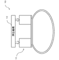
- FIG. 2 is a schematic view showing a state in which the measurement unit of the pressure measurement device of the first embodiment is attached to the measurement object.
- FIG. 3 is a cross-sectional view schematically showing the structure of the measurement unit of the pressure measurement device of the first embodiment and the state at the time of measurement.
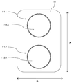
- FIG. 4 is a diagram illustrating the surface of the sensor unit of the pressure measurement device according to the first embodiment that is in contact with the object to be measured.
- FIG. 5 is a block diagram schematically illustrating the functional configuration of the control unit of the pressure measurement device of the first embodiment.
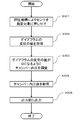
- FIG. 6 is a flowchart showing an example of the flow of processing performed by the pressure measurement device of the first embodiment.
- FIG. 7 is a schematic cross-sectional view for explaining the state of the contact portion when the pressure measurement device is pressed against the measurement object.
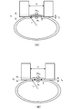
- 8A is a schematic cross-sectional view showing the state of the first pressure sensor and the measurement object when the measurement unit of the pressure measurement device of the first embodiment is pressed against the measurement object
- FIG. 8B is a schematic view It is a schematic sectional drawing showing the state of the 2nd pressure sensor at the time of pressing the measurement part of a pressure measuring device on a measuring object, and a measuring object.
- FIG. 9 is a block diagram showing a functional configuration of a pressure measurement device according to a modification of the first embodiment.
- FIG. 10 is a flowchart showing a flow of internal pressure measurement processing by the pressure measurement device according to the modification of the first embodiment.
- FIG. 11 is a schematic cross-sectional view showing the configuration of the sensor unit of the pressure measurement device according to the second embodiment.
- FIG. 12 is a flowchart showing a flow of internal pressure measurement processing by the pressure measurement device according to the second embodiment.
- FIG. 13 is a block diagram showing a functional configuration of a pressure measurement device according to a modification of the second embodiment.
- FIG. 14 is a flowchart showing a flow of internal pressure measurement processing by the pressure measurement device according to the modification of the second embodiment.
- the pressure measurement device is a device capable of measuring the internal pressure of an object having a fluid in an internal space surrounded by a curved surface by the tonometry method.
- the surface layer of the object to be measured is pressed with an appropriate pressure so that a flat portion is generated, thereby suppressing the influence of the tension acting on the surface of the object to be measured, and in the flat portion
- the internal pressure and the external pressure of the object to be measured are balanced, and the internal pressure of the object to be measured is measured.
- FIG. 1 is a block diagram showing an entire configuration of a pressure measuring device 1 of the present embodiment.
- the pressure measurement device 1 generally includes a measurement unit 10, a control unit 20, an input unit 30, a storage unit 40, and an output unit 50.
- the pressure measuring device 1 may be a stationary type device that can be used by placing the measurement object on a fixed base at the time of measurement, or a portable type that can be used by being attached to the measurement object. It may be an apparatus.
- the measuring unit 10 measures the internal pressure of the object to be measured by the sensor unit 11.
- FIG. 2 is a schematic view showing a state in which the measurement unit 10 is attached to a measurement object (for example, a water hose)
- FIG. 3 is a cross-sectional view schematically showing a structure of the measurement unit 10 and a state at the time of measurement.
- the measuring unit 10 includes a sensor unit 11 and a pressing mechanism 12 for pressing the sensor unit 11 against the object to be measured, and the sensor unit 11 is provided on the surface layer of the object to be measured It is arranged to touch.
- FIG. 4 is a view showing the surface of the sensor unit 11 on the side in contact with the measurement object.
- the first pressure sensor 111 and the second pressure sensor 112 are arranged side by side, and the alignment direction A of the sensors coincides with the longitudinal direction of the object to be measured.
- the measuring unit 10 is attached to the object to be measured.
- Each of the first and second pressure sensors includes a circular diaphragm and a pressure-sensitive element formed thereon, and an electrical resistance generated by distortion of the pressure-sensitive element via the pressure-applied diaphragm It detects changes. That is, when displacement (distortion) occurs in the diaphragm, the displacement can be measured.
- the diaphragm (hereinafter referred to as a first diaphragm) 111A of the first pressure sensor 111 and the diaphragm (hereinafter referred to as a second diaphragm) 112A of the second pressure sensor have different thicknesses, and the first diaphragm 111A is a second diaphragm. It is thinner than the diaphragm 112A. That is, the elastic modulus of the first diaphragm 111A is smaller than that of the second diaphragm 112A.
- each diaphragm is different, but it is sufficient if the elastic modulus is different for each diaphragm.
- the elastic modulus of each diaphragm is different by changing the material of the diaphragm. You may
- the pressing mechanism 12 includes, for example, an air bladder and a pump for adjusting the internal pressure of the air bladder.
- the control unit 20 controls the pump to increase the internal pressure of the air bag, the expansion of the air bag causes each pressure sensor to be pressed against the surface of the object to be measured.
- the pressing mechanism 12 may be anything as long as it can adjust the pressing force, and is not limited to the one using the air bag.
- the control unit 20 performs various processes such as control of each unit of the pressure measurement device 1, recording / analysis of measured data, and input / output of data.
- the control unit 20 includes a processor, a read only memory (ROM), a random access memory (RAM), and the like.
- the function of the control unit 20 described later is realized by the processor reading and executing a program stored in the ROM or the storage unit 40.
- the RAM functions as a work memory when the control unit 20 performs various processes.
- the input unit 30 provides an operation interface to the user.
- an operation button for example, an operation button, a switch, a touch panel, or the like can be used.
- the storage unit 40 is a storage medium capable of storing and reading data, and is a program executed by the control unit 20, measurement data obtained from the measurement unit 10, and various data obtained by processing the measurement data.
- a flash memory is used as the storage unit 40.
- the storage unit 40 may be a portable type such as a memory card, or may be incorporated in the pressure measurement device 1.
- the output unit 50 provides an interface for outputting information to the user.
- a liquid crystal display, a speaker or the like can be used.
- a display device other than a liquid crystal display an audio output device other than a speaker
- a communication device for performing data communication with other devices etc.
- the data communication system in the communication device is wired. It may be wireless or may be wireless. Moreover, it is also possible to use combining these.
- FIG. 5 is a block diagram schematically showing the functional configuration of the control unit 20.
- the control unit 20 obtains a first sensor output value holding unit 21, a second sensor output value holding unit 22, a first diaphragm displacement value acquisition 23, and a second diaphragm displacement value acquisition. It has a section 24 and an internal pressure calculation section 25.
- the control unit 20 executes the necessary programs to exhibit the functions of these units.
- the first sensor output value holding unit 21 has a function of holding the pressure value output as an electric signal from the pressure-sensitive element of the first pressure sensor 111, and the second sensor output value holding unit 22 has a second pressure. It is a function to hold the pressure value output as an electrical signal from the pressure sensitive element of the sensor 112.
- the first diaphragm displacement value acquiring unit 23 is a function of acquiring the displacement value of the first diaphragm 111A due to the sensor unit 11 being pressed against the measurement object, and the second diaphragm displacement value acquiring unit 24 similarly This is a function of acquiring the displacement value of the two diaphragms 112A.
- the displacement value of each diaphragm is calculated based on the output value of each of the first pressure sensor 111 and the second pressure sensor 112.
- the internal pressure calculation unit 25 uses values obtained from the first sensor output value holding unit 21, the second sensor output value holding unit 22, the first diaphragm displacement value acquiring unit 23, and the second diaphragm displacement value acquiring unit 24. On the basis of this, it is a function to calculate the internal pressure by excluding the influence of the tension of the object to be measured by a predetermined calculation formula.
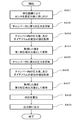
- Drawing 6 is a flow chart which shows an example of the flow of processing which pressure measurement device 1 concerning this example performs.
- the control part 20 controls the press mechanism 12 of the measurement part 10 first, presses the sensor part 11 on a measurement object so that a flat part may arise in the surface layer of a measurement object, and its pressing force Are maintained in an appropriate state (step S101).
- step S102 the output values of the first pressure sensor 111 and the second pressure sensor 112 of the sensor unit 11 and the displacement values of the first diaphragm 111A and the second diaphragm 112A are obtained (step S102).
- step S103 the internal pressure is measured by calculating the value obtained by eliminating the influence of tension using the value obtained in step S102 and a predetermined mathematical formula (step S103).
- the predetermined equation is stored in advance in the ROM or the storage unit 40.
- the calculated value is output to the output unit 50 (for example, a liquid crystal display) (step S104).
- FIG. 7 is a schematic cross-sectional view of a state in which a pressure sensor provided with a circular diaphragm of diameter a is pressed against an object to be measured of the internal pressure Pi.
- Po represents the external pressure acting on the measurement object
- y represents the displacement in the normal direction of the diaphragm
- T represents the tension acting on the surface of the measurement object
- r represents the radius of the arc displacement of the diaphragm.
- the diaphragm pressed against the object to be measured is not completely flat but is distorted in a circular arc and displaced, and a force obtained by adding the influence T / r by the tension of the object to be measured to the internal pressure Pi And the external pressure Po balance. That is, the external pressure Po does not accurately represent the internal pressure Pi, and the following relational expression (1) holds.
- the internal pressure Pi of the object to be measured can be determined by the following equation (3) from the equations (1) and (2).
- the displacement y in the normal direction of the diaphragm is the value of the external pressure Po, the Poisson's ratio v of the diaphragm, and the Young's modulus of the diaphragm (elasticity The ratio can be obtained by each constant of E, thickness t of the diaphragm, and diameter a of the diaphragm.
- the displacement of the diaphragm is thus obtained from the above-described constants and the output value (i.e., Po) of the sensor.
- each constant of v, E, t, and a is fixed for every diaphragm mounted in a sensor, it is good to be beforehand registered into a memory
- the internal pressure Pi can be accurately obtained by the above equation (3).
- the internal pressure Pi can be determined accurately, this can not be done due to the structure of the sensor using the diaphragm.
- FIG. 8 is a schematic cross-sectional view showing the state of each sensor and the measurement object when the measurement unit 10 is pressed against the measurement object, and FIG. 8A shows the state of the first pressure sensor 111 and the measurement object. 8B represents the second pressure sensor 112 and the state of the object to be measured.
- the thickness of the first diaphragm 111A and the thickness of the second diaphragm 112A are different, and as shown in FIG. 8, the magnitude of the displacement in the normal direction of each diaphragm is different.
- FIG. 8 is a schematic cross-sectional view showing the state of each sensor and the measurement object when the measurement unit 10 is pressed against the measurement object
- FIG. 8A shows the state of the first pressure sensor 111 and the measurement object.
- 8B represents the second pressure sensor 112 and the state of the object to be measured.
- the thickness of the first diaphragm 111A and the thickness of the second diaphragm 112A are different, and as shown in FIG. 8, the magnitude of the displacement
- t1 represents the thickness of the first diaphragm 111A
- t2 represents the thickness of the second diaphragm 112A
- y1 represents the displacement of the first diaphragm 111A
- y2 represents the displacement of the second diaphragm 112A.
- control unit 20 uses the equation (7) held in advance, the values of the outputs of the first pressure sensor 111 and the second pressure sensor 112 (that is, Po 1 and Po 2 ), and the first diaphragm 111A.
- the internal pressure Pi of the object to be measured is calculated using the values of the respective displacements (i.e., y 1 and y 2 ) of the second diaphragm 112A.
- the sensor unit 11 is configured to include two sensors each having different diaphragm elasticity, but may be configured to include only one sensor.
- the flow of processing for functional configuration and internal pressure measurement is as follows.
- FIG. 9 is a block diagram showing a functional configuration of the pressure measurement device 1 according to the modification
- FIG. 10 is a flowchart showing a flow of internal pressure measurement processing by the pressure measurement device 1 according to the modification.
- the control unit 20 of the pressure measurement device 1 according to the present modification has a first pressing sensor information holding unit 201, a second pressing sensor information holding unit 202, and internal pressure calculation as basic functions. And a unit 203.
- the configuration of the entire apparatus other than the number of sensors of the sensor unit 11 and the function of the control unit 20 is basically the same as that of the first embodiment.
- the control unit 20 first controls the pressing mechanism 12 of the measuring unit 10, presses the sensor unit 11 against the object to be measured with the first pressing force, and Maintain (step S201). Then, the output value of the sensor unit 11 and the value of the displacement of the diaphragm are acquired (step S202), and this is held in the first pressing time sensor information holding unit 201 (step S203).
- step S204 the pressing mechanism 12 of the measuring unit 10 is controlled again, the sensor unit 11 is pressed against the object to be measured by the second pressing force, and the state is maintained (step S204). Then, the output value of the sensor unit 11 and the value of the displacement of the diaphragm are obtained (step S205), and this is held in the second pressing time sensor information holding unit 202 (step S206).
- the sensor output i.e., Po
- the pressing force that presses the sensor against the measurement object.
- Multiple values of diaphragm displacement i.e. y
- the first pressing force and the second pressing force are set as numerical values.
- the pressing mechanism may be controlled to obtain the first displacement value and the second displacement value.
- the pressure measuring device 1 As described above, by configuring the pressure measuring device 1 as in the present modification, the number of sensors mounted in the device can be reduced to one, which contributes to downsizing and cost reduction of the device. Becomes possible.
- the pressure measurement device 1 may be configured to include a tension calculation unit as a function of the control unit 20 so that the tension of the measurement object can be measured.
- the tension calculation unit is a function of calculating the tension of the measurement object by a predetermined calculation formula.
- the tension T of the object to be measured may be determined by the following equation (8) obtained from the above equation (5) and equation (6) based on the plurality of sensor output values and the plurality of diaphragm displacement values. it can.
- T can also be determined by the following equation (9) obtained from the above equation (5) based on the value of the internal pressure Pi 1 .
- the internal pressure of the measurement object is accurately measured by substituting the value into the above equation (3). be able to. That is, if one sensor output value and one diaphragm displacement value can be obtained, the internal pressure can be accurately measured based on this, so in the case where there is one sensor provided as in the above-mentioned first modification. Even if it is, it becomes possible to measure the internal pressure of the measurement object continuously.
- Example 2 Next, another embodiment of the present invention will be described.
- the present embodiment is different from the first embodiment in the structure of the sensor unit 11 and the method of obtaining the internal pressure excluding the influence of the tension of the object to be measured is different.
- As such components are provided with the same reference numerals, detailed description will be omitted.
- FIG. 11 is a schematic cross-sectional view showing the configuration of the measurement unit 10 of the pressure measurement device according to the present embodiment.
- the sensor unit 11 includes a circular diaphragm 113 and a pressure sensitive element formed thereon, and further includes an internal sealed space (hereinafter referred to as a chamber) 114 in which the diaphragm 113 is a part of a wall.
- a chamber internal pressure sensor 116 for measuring the pressure in the chamber 114 and a chamber internal pressure adjustment pump (hereinafter referred to as a pump) 117 for adjusting the internal pressure by pressurizing and depressurizing the inside of the chamber 114 are further provided.
- the chamber internal pressure sensor 116 in the present embodiment corresponds to the sensor internal pressure measuring means
- the pump 117 corresponds to the sensor internal pressure adjusting means.
- FIG. 12 is a flowchart showing the flow of internal pressure measurement processing by the pressure measurement device according to the present embodiment.
- the control unit 20 of the pressure measurement device according to the present embodiment first controls the pressing mechanism 12 of the measurement unit 10 so that a flat portion is generated on the surface layer of the measurement object.
- the sensor unit 11 is pressed, and the state is maintained (step S301).
- step S302 the value of the displacement in the normal direction of the diaphragm 113 is measured
- the pump 117 is controlled so that the value becomes 0 (step S303).
- the output value of the chamber internal pressure sensor 116 in the said state is obtained (step S304), and this is output to the output part 50 (step S305).
- the diaphragm 113 when pressed against the object to be measured, the diaphragm 113 is distorted in a circular arc shape, causing displacement in the normal direction with respect to the object to be measured.
- the diaphragm 113 is pushed back so that it is completely flat (that is, the value of the displacement in the normal direction of the diaphragm is set to 0).
- the pressure in the chamber 114 are completely balanced without being affected by the tension.
- the output value of the chamber internal pressure sensor 116 as the internal pressure of the object to be measured, it is possible to eliminate the influence of the tension of the object to be measured and to accurately measure the internal pressure value.
- FIG. 13 is a block diagram showing a functional configuration of a pressure measurement device 1 according to a modification of the second embodiment
- FIG. 14 is a flowchart showing a flow of internal pressure measurement processing by the pressure measurement device 1 according to the present modification.
- the control unit 20 of the pressure measurement device 1 according to the present modification has a first pressure sensor information holding unit 401 and a second pressure sensor information holding unit 402 as basic functions.
- An internal pressure calculation unit 403 is included.
- the configuration of the entire apparatus is basically the same as that of the second embodiment.
- the control unit 20 first controls the pressing mechanism 12 of the measuring unit 10 to press the sensor unit 11 against the object to be measured (step S401).
- a first pressure is applied to the chamber, and the state is maintained (step S402).
- the output value of the sensor unit 11 and the value of the displacement of the diaphragm 113 are acquired (step S403), and this is held in the first pressure sensor information holding unit 401 (step S404).
- step S405 the pump 117 is controlled to apply a second pressure into the chamber 114, and the state is maintained.
- the output value of the sensor unit 11 and the value of the displacement of the diaphragm 113 are acquired (step S406), and this is held in the second pressure sensor information holding unit 402 (step S407).
- step S402 and step S405 the first pressure and the second pressure are set as numerical values.
- the pump 117 may be controlled to obtain the first displacement value and the second displacement value.
- the internal pressure is measured by calculating (step S408). Further, the calculated value is output to the output unit 50 (step S409).
- Pc 1 in the above equation (10) is the chamber internal pressure at the first pressurization
- Pc 2 is the chamber internal pressure at the second pressurization
- y 1 is the displacement of the diaphragm at the first pressurization
- y 2 is the second The displacement of the diaphragm 113 at the time of pressurization is shown.
- the internal pressure of the object can be measured without completely flattening the diaphragm 113. Therefore, a complicated and precise pressure for completely flattening the diaphragm 113. Control is not required, and the cost of the device can be reduced.
- the functional configuration of the device may be configured to include a tension calculation unit as a function of the control unit 20.
- the tension calculation unit is a function of calculating the tension of the measurement object by a predetermined calculation formula.
- the tension T may be obtained from the above-mentioned equation (9) and the value of the internal pressure obtained once.
- the sensor output value (Po) and the displacement value (y) of the diaphragm 113 can be continuously obtained.
- the diameter a is a fixed value
- the internal pressure of the object to be measured can be accurately measured by substituting these and the value of the tension T obtained above into the equation (3).
- it is also possible to measure the internal pressure continuously based on Po and y obtained continuously it becomes possible to measure the internal pressure of a measurement object continuously.
- ⁇ Others> The above examples merely illustrate the present invention, and the present invention is not limited to the above specific embodiments. The present invention is capable of various modifications and combinations within the scope of the technical idea.
- a plurality of sensors of the sensor unit 11 may be provided on the array in the direction B in FIG. In this way, even when the pressure measuring device 1 can not be attached to the measurement object itself, for example, when the measurement object is the radial artery, the value of the sensor showing the best measurement result is used, It can measure stably.
- the pressure sensor may be formed by MEMS (Micro Electro Mechanical Systems), and in this case, may be integrally formed with a part or all of the control unit 20. Furthermore, a plurality of pressure sensors may be formed on one chip. With such a configuration, the entire apparatus can be miniaturized, and the apparatus can be applied to a small measurement object.
- MEMS Micro Electro Mechanical Systems
- the pressure sensor may be formed of a pressure sensitive film. In this way, the adhesion to the object to be measured is improved, and the accuracy of the measurement can be enhanced. In addition, when the object to be measured is an organ of a living body, the mountability of the device can be improved, and discomfort can be reduced.
- the measurement result is output to the output unit.
- the measurement value may be stored in the storage unit and stored together with this.
- the output unit is not necessarily required, and may be configured to record only the measured value in the storage unit.
- the scope of application of the present invention is wide, and the measurement object is not limited to the water hose exemplified in the above embodiment.
- the present invention is applicable to various kinds of cushions including living organs such as blood vessels, air mats, water beds and the like.
Landscapes
- Health & Medical Sciences (AREA)
- Physics & Mathematics (AREA)
- General Physics & Mathematics (AREA)
- Life Sciences & Earth Sciences (AREA)
- Vascular Medicine (AREA)
- Cardiology (AREA)
- Heart & Thoracic Surgery (AREA)
- Surgery (AREA)
- Biophysics (AREA)
- Pathology (AREA)
- Engineering & Computer Science (AREA)
- Biomedical Technology (AREA)
- Ophthalmology & Optometry (AREA)
- Medical Informatics (AREA)
- Molecular Biology (AREA)
- Physiology (AREA)
- Animal Behavior & Ethology (AREA)
- General Health & Medical Sciences (AREA)
- Public Health (AREA)
- Veterinary Medicine (AREA)
- Chemical & Material Sciences (AREA)
- Analytical Chemistry (AREA)
- Measuring Fluid Pressure (AREA)
- Measuring Pulse, Heart Rate, Blood Pressure Or Blood Flow (AREA)
Priority Applications (3)
| Application Number | Priority Date | Filing Date | Title |
|---|---|---|---|
| DE112018005152.8T DE112018005152T5 (de) | 2017-09-14 | 2018-09-12 | Druckmesseinrichtung und druckmessverfahren |
| CN201880052968.5A CN111033203B (zh) | 2017-09-14 | 2018-09-12 | 压力测定装置和压力测定方法 |
| US16/791,294 US20200182723A1 (en) | 2017-09-14 | 2020-02-14 | Pressure measurement device and pressure measurement method |
Applications Claiming Priority (2)
| Application Number | Priority Date | Filing Date | Title |
|---|---|---|---|
| JP2017-177133 | 2017-09-14 | ||
| JP2017177133A JP6852631B2 (ja) | 2017-09-14 | 2017-09-14 | 圧力測定装置、及び圧力測定方法 |
Related Child Applications (1)
| Application Number | Title | Priority Date | Filing Date |
|---|---|---|---|
| US16/791,294 Continuation US20200182723A1 (en) | 2017-09-14 | 2020-02-14 | Pressure measurement device and pressure measurement method |
Publications (1)
| Publication Number | Publication Date |
|---|---|
| WO2019054403A1 true WO2019054403A1 (ja) | 2019-03-21 |
Family
ID=65723667
Family Applications (1)
| Application Number | Title | Priority Date | Filing Date |
|---|---|---|---|
| PCT/JP2018/033770 Ceased WO2019054403A1 (ja) | 2017-09-14 | 2018-09-12 | 圧力測定装置、及び圧力測定方法 |
Country Status (5)
| Country | Link |
|---|---|
| US (1) | US20200182723A1 (https=) |
| JP (1) | JP6852631B2 (https=) |
| CN (1) | CN111033203B (https=) |
| DE (1) | DE112018005152T5 (https=) |
| WO (1) | WO2019054403A1 (https=) |
Families Citing this family (3)
| Publication number | Priority date | Publication date | Assignee | Title |
|---|---|---|---|---|
| CN111920394B (zh) * | 2020-06-23 | 2024-10-22 | 泰安市泰医医疗器械有限公司 | 气囊式脉搏探头及其制作和使用方法 |
| US20240167900A1 (en) * | 2021-03-29 | 2024-05-23 | Sony Group Corporation | Pressure measurement method, control method, pressure measurement device, and analyzer |
| CN118022144B (zh) * | 2024-04-11 | 2024-06-21 | 湖南圣安杰医疗科技有限公司 | 一种球囊扩张压力泵压力监测及处理系统 |
Citations (4)
| Publication number | Priority date | Publication date | Assignee | Title |
|---|---|---|---|---|
| JPS63293424A (ja) * | 1987-05-27 | 1988-11-30 | Koorin Denshi Kk | 脈波検出装置 |
| JPH0234146A (ja) * | 1988-07-26 | 1990-02-05 | Koorin Denshi Kk | 圧脈波検出装置 |
| WO1994016616A1 (fr) * | 1993-01-28 | 1994-08-04 | Université De Rennes 1 | Tensiometre a mesure en continu, et procede correspondant |
| JP2012130362A (ja) * | 2010-12-17 | 2012-07-12 | A & D Co Ltd | 動脈血管検査装置 |
Family Cites Families (6)
| Publication number | Priority date | Publication date | Assignee | Title |
|---|---|---|---|---|
| JP4014006B2 (ja) * | 2004-06-17 | 2007-11-28 | 株式会社山武 | 圧力センサ |
| EP2000790B1 (en) * | 2006-03-29 | 2012-09-12 | JMS Co., Ltd. | Pressure detection device |
| US20070276267A1 (en) * | 2006-05-24 | 2007-11-29 | A. C. Cossor & Son (Surgical) Limited | Deflation control valve |
| US8042401B2 (en) * | 2008-06-12 | 2011-10-25 | Rosemount, Inc. | Isolation system for process pressure measurement |
| JP5353268B2 (ja) * | 2009-01-28 | 2013-11-27 | オムロンヘルスケア株式会社 | ダイヤフラムポンプおよび血圧計 |
| US8704538B2 (en) * | 2010-07-01 | 2014-04-22 | Mks Instruments, Inc. | Capacitance sensors |
-
2017
- 2017-09-14 JP JP2017177133A patent/JP6852631B2/ja active Active
-
2018
- 2018-09-12 DE DE112018005152.8T patent/DE112018005152T5/de not_active Ceased
- 2018-09-12 CN CN201880052968.5A patent/CN111033203B/zh active Active
- 2018-09-12 WO PCT/JP2018/033770 patent/WO2019054403A1/ja not_active Ceased
-
2020
- 2020-02-14 US US16/791,294 patent/US20200182723A1/en not_active Abandoned
Patent Citations (4)
| Publication number | Priority date | Publication date | Assignee | Title |
|---|---|---|---|---|
| JPS63293424A (ja) * | 1987-05-27 | 1988-11-30 | Koorin Denshi Kk | 脈波検出装置 |
| JPH0234146A (ja) * | 1988-07-26 | 1990-02-05 | Koorin Denshi Kk | 圧脈波検出装置 |
| WO1994016616A1 (fr) * | 1993-01-28 | 1994-08-04 | Université De Rennes 1 | Tensiometre a mesure en continu, et procede correspondant |
| JP2012130362A (ja) * | 2010-12-17 | 2012-07-12 | A & D Co Ltd | 動脈血管検査装置 |
Also Published As
| Publication number | Publication date |
|---|---|
| JP2019052936A (ja) | 2019-04-04 |
| CN111033203A (zh) | 2020-04-17 |
| JP6852631B2 (ja) | 2021-03-31 |
| US20200182723A1 (en) | 2020-06-11 |
| CN111033203B (zh) | 2021-09-03 |
| DE112018005152T5 (de) | 2020-09-03 |
Similar Documents
| Publication | Publication Date | Title |
|---|---|---|
| Wang et al. | A silicon-based shear force sensor: development and characterization | |
| Atalay et al. | A highly sensitive capacitive‐based soft pressure sensor based on a conductive fabric and a microporous dielectric layer | |
| WO2019054403A1 (ja) | 圧力測定装置、及び圧力測定方法 | |
| JP6651971B2 (ja) | 脈波検出装置、生体情報測定装置、脈波検出方法、及び、脈波検出プログラム | |
| JP7503274B2 (ja) | 血圧測定のためのセンサモジュール及びそれを用いた手首式携帯用血圧測定装置 | |
| KR20200141244A (ko) | 휴대용 혈압 측정 장치 | |
| CN110036269A (zh) | 压力传感器 | |
| US11668616B2 (en) | Stretchable tactile sleeve for robotic extremities | |
| JP2020006208A (ja) | 時計型血圧測定装置 | |
| KR102082657B1 (ko) | 경도 측정장치 | |
| KR102315952B1 (ko) | 혈압 측정을 위한 센서모듈 및 이를 이용한 손목 착용형 휴대용 혈압 측정 장치 | |
| Orthner et al. | Development, fabrication, and characterization of hydrogel based piezoresistive pressure sensors with perforated diaphragms | |
| WO2016147503A1 (ja) | Mems圧力センサとその位置決め方法 | |
| Kohli et al. | MEMS based pressure sensor simulation for healthcare and biomedical applications | |
| Gu et al. | Smart structure with elastomeric contact surface for prosthetic fingertip sensitivity development | |
| JP2019052936A5 (https=) | ||
| JP6584297B2 (ja) | 脈波測定装置及び脈波測定方法 | |
| CN111795771A (zh) | 具有多个压力感测元件的压力传感器 | |
| Youssef et al. | Methods to improve reliability of bulge test technique to extract mechanical properties of thin films | |
| Arjunan et al. | Modeling and analysis of a multi bossed beam membrane sensor for environmental applications | |
| JP5559617B2 (ja) | 押込み試験機 | |
| JP3883000B2 (ja) | 柔らかさ測定方法及び柔らかさ測定装置 | |
| CN112692848A (zh) | 一种柔性气动臂以及末端控制系统 | |
| WO2007083546A1 (ja) | 触覚センサ装置 | |
| Garinei et al. | Measurement of pressure distribution on a membrane of a pump for biomedical applications through capacitive film sensors |
Legal Events
| Date | Code | Title | Description |
|---|---|---|---|
| 121 | Ep: the epo has been informed by wipo that ep was designated in this application |
Ref document number: 18856526 Country of ref document: EP Kind code of ref document: A1 |
|
| DPE1 | Request for preliminary examination filed after expiration of 19th month from priority date (pct application filed from 20040101) | ||
| 122 | Ep: pct application non-entry in european phase |
Ref document number: 18856526 Country of ref document: EP Kind code of ref document: A1 |