WO2019054403A1 - Pressure measurement device and pressure measurement method - Google Patents
Pressure measurement device and pressure measurement method Download PDFInfo
- Publication number
- WO2019054403A1 WO2019054403A1 PCT/JP2018/033770 JP2018033770W WO2019054403A1 WO 2019054403 A1 WO2019054403 A1 WO 2019054403A1 JP 2018033770 W JP2018033770 W JP 2018033770W WO 2019054403 A1 WO2019054403 A1 WO 2019054403A1
- Authority
- WO
- WIPO (PCT)
- Prior art keywords
- pressure
- diaphragm
- value
- displacement
- measurement
- Prior art date
Links
Images


Classifications
-
- G—PHYSICS
- G01—MEASURING; TESTING
- G01L—MEASURING FORCE, STRESS, TORQUE, WORK, MECHANICAL POWER, MECHANICAL EFFICIENCY, OR FLUID PRESSURE
- G01L9/00—Measuring steady of quasi-steady pressure of fluid or fluent solid material by electric or magnetic pressure-sensitive elements; Transmitting or indicating the displacement of mechanical pressure-sensitive elements, used to measure the steady or quasi-steady pressure of a fluid or fluent solid material, by electric or magnetic means
- G01L9/0041—Transmitting or indicating the displacement of flexible diaphragms
- G01L9/0051—Transmitting or indicating the displacement of flexible diaphragms using variations in ohmic resistance
-
- G—PHYSICS
- G01—MEASURING; TESTING
- G01L—MEASURING FORCE, STRESS, TORQUE, WORK, MECHANICAL POWER, MECHANICAL EFFICIENCY, OR FLUID PRESSURE
- G01L7/00—Measuring the steady or quasi-steady pressure of a fluid or a fluent solid material by mechanical or fluid pressure-sensitive elements
- G01L7/02—Measuring the steady or quasi-steady pressure of a fluid or a fluent solid material by mechanical or fluid pressure-sensitive elements in the form of elastically-deformable gauges
-
- A—HUMAN NECESSITIES
- A61—MEDICAL OR VETERINARY SCIENCE; HYGIENE
- A61B—DIAGNOSIS; SURGERY; IDENTIFICATION
- A61B5/00—Measuring for diagnostic purposes; Identification of persons
- A61B5/02—Detecting, measuring or recording pulse, heart rate, blood pressure or blood flow; Combined pulse/heart-rate/blood pressure determination; Evaluating a cardiovascular condition not otherwise provided for, e.g. using combinations of techniques provided for in this group with electrocardiography or electroauscultation; Heart catheters for measuring blood pressure
- A61B5/021—Measuring pressure in heart or blood vessels
- A61B5/022—Measuring pressure in heart or blood vessels by applying pressure to close blood vessels, e.g. against the skin; Ophthalmodynamometers
-
- G—PHYSICS
- G01—MEASURING; TESTING
- G01L—MEASURING FORCE, STRESS, TORQUE, WORK, MECHANICAL POWER, MECHANICAL EFFICIENCY, OR FLUID PRESSURE
- G01L17/00—Devices or apparatus for measuring tyre pressure or the pressure in other inflated bodies
- G01L17/005—Devices or apparatus for measuring tyre pressure or the pressure in other inflated bodies using a sensor contacting the exterior surface, e.g. for measuring deformation
-
- G—PHYSICS
- G01—MEASURING; TESTING
- G01L—MEASURING FORCE, STRESS, TORQUE, WORK, MECHANICAL POWER, MECHANICAL EFFICIENCY, OR FLUID PRESSURE
- G01L19/00—Details of, or accessories for, apparatus for measuring steady or quasi-steady pressure of a fluent medium insofar as such details or accessories are not special to particular types of pressure gauges
- G01L19/06—Means for preventing overload or deleterious influence of the measured medium on the measuring device or vice versa
Definitions
- the present invention relates to a technique for measuring the pressure of a fluid-filled object.
- a tonometry method is known as a method of measuring the internal pressure of a measurement object having an internal space filled with fluid, and a method of measuring blood pressure (that is, measuring the internal pressure of blood vessels) using this principle is known. It has become. Specifically, a pressure sensor is pressed against a blood vessel in the vicinity of the body surface to generate a flat portion on the blood vessel wall which is a curved surface in the natural state, thereby reducing the influence of tension acting on the blood vessel wall. The internal pressure and the external pressure are balanced, and blood pressure is measured noninvasively (see, for example, Patent Document 1).
- the present invention eliminates the influence of tension to be measured and measures an accurate pressure value when performing pressure measurement by tonometry method using a pressure sensor having a diaphragm. Intended to be provided.
- a pressure measurement device is a device that measures the internal pressure of a measurement object having a fluid-filled internal space and a surface layer having a curved surface by tonometry method.
- the pressure sensor includes a pressure sensor, pressing means for pressing the pressure sensor against the object to be measured, and control means for performing various calculations and controlling the operation of the device, the control means comprising the pressure sensor Obtaining a value of displacement in the normal direction of the diaphragm on a contact surface with the measurement object, and eliminating an influence of tension acting on the measurement object based on the acquired value of displacement. It is characterized by
- the tension generated in the distorted portion of the diaphragm which can not be avoided in principle.
- the internal pressure of the object to be measured can be measured without the influence of
- the value of the displacement in the normal direction of the diaphragm may be calculated based on the output of the pressure sensor, or may be measured using a measuring unit other than the pressure sensor. .
- the pressure measuring device has a plurality of pressure sensors having different elasticity of the diaphragm, and the control means acquires values of displacement in the normal direction of the diaphragm in the plurality of pressure sensors.
- An internal pressure measurement value excluding the influence of tension acting on the measurement object is calculated using the plurality of acquired displacement values and the output value of the pressure sensor when each value is acquired. It may be one.
- tension is obtained using a plurality of displacement values obtained according to the difference in elasticity of the diaphragm and the output values of the corresponding pressure sensors when the values of each displacement are acquired. It is possible to formulate simultaneous equations in which the internal pressure of the object of measurement and the internal pressure of the object of measurement are unknown, thereby making it possible to eliminate (eliminate) the influence of tension and to calculate the internal pressure of the object of measurement by calculation.
- the pressing means presses the pressure sensor against the measurement object a plurality of times with different pressing forces
- the control means displaces the diaphragm in the normal direction with respect to each of a plurality of pressings by the different pressing forces.
- the internal pressure which eliminated the influence of the tension acting on the measurement object by using the values of the plurality of displacements and the output values of the pressure sensor when the plurality of acquired displacements were obtained, The measurement value may be calculated.
- the internal pressure of the object to be measured can be determined by the same calculation as described above without increasing the number of pressure sensors, and a more cost-effective device can be provided.
- the pressure sensor further includes a sealed space in which a surface including the diaphragm is a part of a wall, a sensor internal pressure acquiring unit for acquiring a pressure in the sealed space, pressurizing the inside of the sealed space Sensor pressure adjusting means for reducing pressure, and the control means is configured to set the value of the displacement in the normal direction of the diaphragm to 0 in a state where the pressure sensor is pressed against the measurement object.
- the pressure in the enclosed space is adjusted, and the value of the pressure in the enclosed space in which the value of the displacement is zero is the value of the internal pressure of the object to be measured, thereby acting on the object to be measured. To eliminate the influence of tension.
- the sensor internal pressure adjusting means applies pressure a plurality of times at different pressures
- the control means acquires the value of the displacement in the normal direction of the diaphragm for each of the plurality of times of application by the different pressures
- the internal pressure measurement value excluding the influence of the tension acting on the object to be measured is calculated using the plurality of displacement values and the pressure value in the closed space when each value is acquired. , May be.
- the pressure measurement method is a method of measuring the internal pressure of a measurement object provided with a fluid-filled internal space and a surface layer having a curved surface by a tonometry method using a pressure sensor provided with a diaphragm.
- a tension component elimination step for eliminating the influence of tension acting on the measurement object based on the value of the displacement of the direction.
- the strain acquisition step a plurality of values of displacement in the normal direction of the diaphragm are obtained, and in the tension component elimination step, the plurality of values obtained in the strain acquisition step and respective values are obtained.
- the internal pressure measurement value excluding the influence of the tension acting on the measurement object may be calculated using the output value of the pressure sensor at that time.
- the influence of tension and measurement are performed using a plurality of values for the obtained displacement of the diaphragm and the output value of the corresponding pressure sensor when the value of each displacement is obtained. It is possible to set up a simultaneous equation in which the internal pressure of the object is unknown, which makes it possible to eliminate (eliminate) the influence of tension and to calculate the internal pressure of the measurement object by calculation.
- the values of the displacement of the plurality of portions of the measurement object may be acquired by a plurality of pressure sensors having different elasticity of the diaphragm.
- the pressure sensor is pressed against the measurement object a plurality of times with different pressing forces, so that the value of the displacement in the normal direction of the diaphragm according to the different pressing forces is obtained a plurality of times You may
- the pressure sensor further includes an enclosed space in which a surface provided with the diaphragm is a part of a wall, and in the tension component eliminating step, the pressure sensor is pressed against the object to be measured.
- the inside of the closed space is pressurized so that the value of the displacement in the normal direction of the diaphragm is 0, and the pressure on the closed space after the pressure is applied to act on the object to be measured. The effect of tension may be eliminated.
- the pressure sensor further includes an enclosed space in which a surface provided with the diaphragm is a part of a wall, and in the strain acquisition step, the pressure sensor is pressed against the measurement object.
- the value of the displacement in the normal direction of the diaphragm according to the different pressure may be acquired multiple times by controlling the enclosed space multiple times with different pressures.
- FIG. 1 is a block diagram showing an entire configuration of a pressure measurement device of a first embodiment.
- FIG. 2 is a schematic view showing a state in which the measurement unit of the pressure measurement device of the first embodiment is attached to the measurement object.
- FIG. 3 is a cross-sectional view schematically showing the structure of the measurement unit of the pressure measurement device of the first embodiment and the state at the time of measurement.
- FIG. 4 is a diagram illustrating the surface of the sensor unit of the pressure measurement device according to the first embodiment that is in contact with the object to be measured.
- FIG. 5 is a block diagram schematically illustrating the functional configuration of the control unit of the pressure measurement device of the first embodiment.
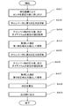
- FIG. 6 is a flowchart showing an example of the flow of processing performed by the pressure measurement device of the first embodiment.
- FIG. 7 is a schematic cross-sectional view for explaining the state of the contact portion when the pressure measurement device is pressed against the measurement object.
- 8A is a schematic cross-sectional view showing the state of the first pressure sensor and the measurement object when the measurement unit of the pressure measurement device of the first embodiment is pressed against the measurement object
- FIG. 8B is a schematic view It is a schematic sectional drawing showing the state of the 2nd pressure sensor at the time of pressing the measurement part of a pressure measuring device on a measuring object, and a measuring object.
- FIG. 9 is a block diagram showing a functional configuration of a pressure measurement device according to a modification of the first embodiment.
- FIG. 10 is a flowchart showing a flow of internal pressure measurement processing by the pressure measurement device according to the modification of the first embodiment.
- FIG. 11 is a schematic cross-sectional view showing the configuration of the sensor unit of the pressure measurement device according to the second embodiment.
- FIG. 12 is a flowchart showing a flow of internal pressure measurement processing by the pressure measurement device according to the second embodiment.
- FIG. 13 is a block diagram showing a functional configuration of a pressure measurement device according to a modification of the second embodiment.
- FIG. 14 is a flowchart showing a flow of internal pressure measurement processing by the pressure measurement device according to the modification of the second embodiment.
- the pressure measurement device is a device capable of measuring the internal pressure of an object having a fluid in an internal space surrounded by a curved surface by the tonometry method.
- the surface layer of the object to be measured is pressed with an appropriate pressure so that a flat portion is generated, thereby suppressing the influence of the tension acting on the surface of the object to be measured, and in the flat portion
- the internal pressure and the external pressure of the object to be measured are balanced, and the internal pressure of the object to be measured is measured.
- FIG. 1 is a block diagram showing an entire configuration of a pressure measuring device 1 of the present embodiment.
- the pressure measurement device 1 generally includes a measurement unit 10, a control unit 20, an input unit 30, a storage unit 40, and an output unit 50.
- the pressure measuring device 1 may be a stationary type device that can be used by placing the measurement object on a fixed base at the time of measurement, or a portable type that can be used by being attached to the measurement object. It may be an apparatus.
- the measuring unit 10 measures the internal pressure of the object to be measured by the sensor unit 11.
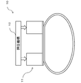
- FIG. 2 is a schematic view showing a state in which the measurement unit 10 is attached to a measurement object (for example, a water hose)
- FIG. 3 is a cross-sectional view schematically showing a structure of the measurement unit 10 and a state at the time of measurement.
- the measuring unit 10 includes a sensor unit 11 and a pressing mechanism 12 for pressing the sensor unit 11 against the object to be measured, and the sensor unit 11 is provided on the surface layer of the object to be measured It is arranged to touch.
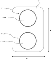
- FIG. 4 is a view showing the surface of the sensor unit 11 on the side in contact with the measurement object.
- the first pressure sensor 111 and the second pressure sensor 112 are arranged side by side, and the alignment direction A of the sensors coincides with the longitudinal direction of the object to be measured.
- the measuring unit 10 is attached to the object to be measured.
- Each of the first and second pressure sensors includes a circular diaphragm and a pressure-sensitive element formed thereon, and an electrical resistance generated by distortion of the pressure-sensitive element via the pressure-applied diaphragm It detects changes. That is, when displacement (distortion) occurs in the diaphragm, the displacement can be measured.
- the diaphragm (hereinafter referred to as a first diaphragm) 111A of the first pressure sensor 111 and the diaphragm (hereinafter referred to as a second diaphragm) 112A of the second pressure sensor have different thicknesses, and the first diaphragm 111A is a second diaphragm. It is thinner than the diaphragm 112A. That is, the elastic modulus of the first diaphragm 111A is smaller than that of the second diaphragm 112A.
- each diaphragm is different, but it is sufficient if the elastic modulus is different for each diaphragm.
- the elastic modulus of each diaphragm is different by changing the material of the diaphragm. You may
- the pressing mechanism 12 includes, for example, an air bladder and a pump for adjusting the internal pressure of the air bladder.
- the control unit 20 controls the pump to increase the internal pressure of the air bag, the expansion of the air bag causes each pressure sensor to be pressed against the surface of the object to be measured.
- the pressing mechanism 12 may be anything as long as it can adjust the pressing force, and is not limited to the one using the air bag.
- the control unit 20 performs various processes such as control of each unit of the pressure measurement device 1, recording / analysis of measured data, and input / output of data.
- the control unit 20 includes a processor, a read only memory (ROM), a random access memory (RAM), and the like.
- the function of the control unit 20 described later is realized by the processor reading and executing a program stored in the ROM or the storage unit 40.
- the RAM functions as a work memory when the control unit 20 performs various processes.
- the input unit 30 provides an operation interface to the user.
- an operation button for example, an operation button, a switch, a touch panel, or the like can be used.
- the storage unit 40 is a storage medium capable of storing and reading data, and is a program executed by the control unit 20, measurement data obtained from the measurement unit 10, and various data obtained by processing the measurement data.
- a flash memory is used as the storage unit 40.
- the storage unit 40 may be a portable type such as a memory card, or may be incorporated in the pressure measurement device 1.
- the output unit 50 provides an interface for outputting information to the user.
- a liquid crystal display, a speaker or the like can be used.
- a display device other than a liquid crystal display an audio output device other than a speaker
- a communication device for performing data communication with other devices etc.
- the data communication system in the communication device is wired. It may be wireless or may be wireless. Moreover, it is also possible to use combining these.
- FIG. 5 is a block diagram schematically showing the functional configuration of the control unit 20.
- the control unit 20 obtains a first sensor output value holding unit 21, a second sensor output value holding unit 22, a first diaphragm displacement value acquisition 23, and a second diaphragm displacement value acquisition. It has a section 24 and an internal pressure calculation section 25.
- the control unit 20 executes the necessary programs to exhibit the functions of these units.
- the first sensor output value holding unit 21 has a function of holding the pressure value output as an electric signal from the pressure-sensitive element of the first pressure sensor 111, and the second sensor output value holding unit 22 has a second pressure. It is a function to hold the pressure value output as an electrical signal from the pressure sensitive element of the sensor 112.
- the first diaphragm displacement value acquiring unit 23 is a function of acquiring the displacement value of the first diaphragm 111A due to the sensor unit 11 being pressed against the measurement object, and the second diaphragm displacement value acquiring unit 24 similarly This is a function of acquiring the displacement value of the two diaphragms 112A.
- the displacement value of each diaphragm is calculated based on the output value of each of the first pressure sensor 111 and the second pressure sensor 112.
- the internal pressure calculation unit 25 uses values obtained from the first sensor output value holding unit 21, the second sensor output value holding unit 22, the first diaphragm displacement value acquiring unit 23, and the second diaphragm displacement value acquiring unit 24. On the basis of this, it is a function to calculate the internal pressure by excluding the influence of the tension of the object to be measured by a predetermined calculation formula.
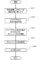
- Drawing 6 is a flow chart which shows an example of the flow of processing which pressure measurement device 1 concerning this example performs.
- the control part 20 controls the press mechanism 12 of the measurement part 10 first, presses the sensor part 11 on a measurement object so that a flat part may arise in the surface layer of a measurement object, and its pressing force Are maintained in an appropriate state (step S101).
- step S102 the output values of the first pressure sensor 111 and the second pressure sensor 112 of the sensor unit 11 and the displacement values of the first diaphragm 111A and the second diaphragm 112A are obtained (step S102).
- step S103 the internal pressure is measured by calculating the value obtained by eliminating the influence of tension using the value obtained in step S102 and a predetermined mathematical formula (step S103).
- the predetermined equation is stored in advance in the ROM or the storage unit 40.
- the calculated value is output to the output unit 50 (for example, a liquid crystal display) (step S104).
- FIG. 7 is a schematic cross-sectional view of a state in which a pressure sensor provided with a circular diaphragm of diameter a is pressed against an object to be measured of the internal pressure Pi.
- Po represents the external pressure acting on the measurement object
- y represents the displacement in the normal direction of the diaphragm
- T represents the tension acting on the surface of the measurement object
- r represents the radius of the arc displacement of the diaphragm.
- the diaphragm pressed against the object to be measured is not completely flat but is distorted in a circular arc and displaced, and a force obtained by adding the influence T / r by the tension of the object to be measured to the internal pressure Pi And the external pressure Po balance. That is, the external pressure Po does not accurately represent the internal pressure Pi, and the following relational expression (1) holds.
- the internal pressure Pi of the object to be measured can be determined by the following equation (3) from the equations (1) and (2).
- the displacement y in the normal direction of the diaphragm is the value of the external pressure Po, the Poisson's ratio v of the diaphragm, and the Young's modulus of the diaphragm (elasticity The ratio can be obtained by each constant of E, thickness t of the diaphragm, and diameter a of the diaphragm.
- the displacement of the diaphragm is thus obtained from the above-described constants and the output value (i.e., Po) of the sensor.
- each constant of v, E, t, and a is fixed for every diaphragm mounted in a sensor, it is good to be beforehand registered into a memory
- the internal pressure Pi can be accurately obtained by the above equation (3).
- the internal pressure Pi can be determined accurately, this can not be done due to the structure of the sensor using the diaphragm.
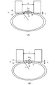
- FIG. 8 is a schematic cross-sectional view showing the state of each sensor and the measurement object when the measurement unit 10 is pressed against the measurement object, and FIG. 8A shows the state of the first pressure sensor 111 and the measurement object. 8B represents the second pressure sensor 112 and the state of the object to be measured.
- the thickness of the first diaphragm 111A and the thickness of the second diaphragm 112A are different, and as shown in FIG. 8, the magnitude of the displacement in the normal direction of each diaphragm is different.
- FIG. 8 is a schematic cross-sectional view showing the state of each sensor and the measurement object when the measurement unit 10 is pressed against the measurement object
- FIG. 8A shows the state of the first pressure sensor 111 and the measurement object.
- 8B represents the second pressure sensor 112 and the state of the object to be measured.
- the thickness of the first diaphragm 111A and the thickness of the second diaphragm 112A are different, and as shown in FIG. 8, the magnitude of the displacement
- t1 represents the thickness of the first diaphragm 111A
- t2 represents the thickness of the second diaphragm 112A
- y1 represents the displacement of the first diaphragm 111A
- y2 represents the displacement of the second diaphragm 112A.
- control unit 20 uses the equation (7) held in advance, the values of the outputs of the first pressure sensor 111 and the second pressure sensor 112 (that is, Po 1 and Po 2 ), and the first diaphragm 111A.
- the internal pressure Pi of the object to be measured is calculated using the values of the respective displacements (i.e., y 1 and y 2 ) of the second diaphragm 112A.
- the sensor unit 11 is configured to include two sensors each having different diaphragm elasticity, but may be configured to include only one sensor.
- the flow of processing for functional configuration and internal pressure measurement is as follows.
- FIG. 9 is a block diagram showing a functional configuration of the pressure measurement device 1 according to the modification
- FIG. 10 is a flowchart showing a flow of internal pressure measurement processing by the pressure measurement device 1 according to the modification.
- the control unit 20 of the pressure measurement device 1 according to the present modification has a first pressing sensor information holding unit 201, a second pressing sensor information holding unit 202, and internal pressure calculation as basic functions. And a unit 203.
- the configuration of the entire apparatus other than the number of sensors of the sensor unit 11 and the function of the control unit 20 is basically the same as that of the first embodiment.
- the control unit 20 first controls the pressing mechanism 12 of the measuring unit 10, presses the sensor unit 11 against the object to be measured with the first pressing force, and Maintain (step S201). Then, the output value of the sensor unit 11 and the value of the displacement of the diaphragm are acquired (step S202), and this is held in the first pressing time sensor information holding unit 201 (step S203).
- step S204 the pressing mechanism 12 of the measuring unit 10 is controlled again, the sensor unit 11 is pressed against the object to be measured by the second pressing force, and the state is maintained (step S204). Then, the output value of the sensor unit 11 and the value of the displacement of the diaphragm are obtained (step S205), and this is held in the second pressing time sensor information holding unit 202 (step S206).
- the sensor output i.e., Po
- the pressing force that presses the sensor against the measurement object.
- Multiple values of diaphragm displacement i.e. y
- the first pressing force and the second pressing force are set as numerical values.
- the pressing mechanism may be controlled to obtain the first displacement value and the second displacement value.
- the pressure measuring device 1 As described above, by configuring the pressure measuring device 1 as in the present modification, the number of sensors mounted in the device can be reduced to one, which contributes to downsizing and cost reduction of the device. Becomes possible.
- the pressure measurement device 1 may be configured to include a tension calculation unit as a function of the control unit 20 so that the tension of the measurement object can be measured.
- the tension calculation unit is a function of calculating the tension of the measurement object by a predetermined calculation formula.
- the tension T of the object to be measured may be determined by the following equation (8) obtained from the above equation (5) and equation (6) based on the plurality of sensor output values and the plurality of diaphragm displacement values. it can.
- T can also be determined by the following equation (9) obtained from the above equation (5) based on the value of the internal pressure Pi 1 .
- the internal pressure of the measurement object is accurately measured by substituting the value into the above equation (3). be able to. That is, if one sensor output value and one diaphragm displacement value can be obtained, the internal pressure can be accurately measured based on this, so in the case where there is one sensor provided as in the above-mentioned first modification. Even if it is, it becomes possible to measure the internal pressure of the measurement object continuously.
- Example 2 Next, another embodiment of the present invention will be described.
- the present embodiment is different from the first embodiment in the structure of the sensor unit 11 and the method of obtaining the internal pressure excluding the influence of the tension of the object to be measured is different.
- As such components are provided with the same reference numerals, detailed description will be omitted.
- FIG. 11 is a schematic cross-sectional view showing the configuration of the measurement unit 10 of the pressure measurement device according to the present embodiment.
- the sensor unit 11 includes a circular diaphragm 113 and a pressure sensitive element formed thereon, and further includes an internal sealed space (hereinafter referred to as a chamber) 114 in which the diaphragm 113 is a part of a wall.
- a chamber internal pressure sensor 116 for measuring the pressure in the chamber 114 and a chamber internal pressure adjustment pump (hereinafter referred to as a pump) 117 for adjusting the internal pressure by pressurizing and depressurizing the inside of the chamber 114 are further provided.
- the chamber internal pressure sensor 116 in the present embodiment corresponds to the sensor internal pressure measuring means
- the pump 117 corresponds to the sensor internal pressure adjusting means.
- FIG. 12 is a flowchart showing the flow of internal pressure measurement processing by the pressure measurement device according to the present embodiment.
- the control unit 20 of the pressure measurement device according to the present embodiment first controls the pressing mechanism 12 of the measurement unit 10 so that a flat portion is generated on the surface layer of the measurement object.
- the sensor unit 11 is pressed, and the state is maintained (step S301).
- step S302 the value of the displacement in the normal direction of the diaphragm 113 is measured
- the pump 117 is controlled so that the value becomes 0 (step S303).
- the output value of the chamber internal pressure sensor 116 in the said state is obtained (step S304), and this is output to the output part 50 (step S305).
- the diaphragm 113 when pressed against the object to be measured, the diaphragm 113 is distorted in a circular arc shape, causing displacement in the normal direction with respect to the object to be measured.
- the diaphragm 113 is pushed back so that it is completely flat (that is, the value of the displacement in the normal direction of the diaphragm is set to 0).
- the pressure in the chamber 114 are completely balanced without being affected by the tension.
- the output value of the chamber internal pressure sensor 116 as the internal pressure of the object to be measured, it is possible to eliminate the influence of the tension of the object to be measured and to accurately measure the internal pressure value.
- FIG. 13 is a block diagram showing a functional configuration of a pressure measurement device 1 according to a modification of the second embodiment
- FIG. 14 is a flowchart showing a flow of internal pressure measurement processing by the pressure measurement device 1 according to the present modification.
- the control unit 20 of the pressure measurement device 1 according to the present modification has a first pressure sensor information holding unit 401 and a second pressure sensor information holding unit 402 as basic functions.
- An internal pressure calculation unit 403 is included.
- the configuration of the entire apparatus is basically the same as that of the second embodiment.
- the control unit 20 first controls the pressing mechanism 12 of the measuring unit 10 to press the sensor unit 11 against the object to be measured (step S401).
- a first pressure is applied to the chamber, and the state is maintained (step S402).
- the output value of the sensor unit 11 and the value of the displacement of the diaphragm 113 are acquired (step S403), and this is held in the first pressure sensor information holding unit 401 (step S404).
- step S405 the pump 117 is controlled to apply a second pressure into the chamber 114, and the state is maintained.
- the output value of the sensor unit 11 and the value of the displacement of the diaphragm 113 are acquired (step S406), and this is held in the second pressure sensor information holding unit 402 (step S407).
- step S402 and step S405 the first pressure and the second pressure are set as numerical values.
- the pump 117 may be controlled to obtain the first displacement value and the second displacement value.
- the internal pressure is measured by calculating (step S408). Further, the calculated value is output to the output unit 50 (step S409).
- Pc 1 in the above equation (10) is the chamber internal pressure at the first pressurization
- Pc 2 is the chamber internal pressure at the second pressurization
- y 1 is the displacement of the diaphragm at the first pressurization
- y 2 is the second The displacement of the diaphragm 113 at the time of pressurization is shown.
- the internal pressure of the object can be measured without completely flattening the diaphragm 113. Therefore, a complicated and precise pressure for completely flattening the diaphragm 113. Control is not required, and the cost of the device can be reduced.
- the functional configuration of the device may be configured to include a tension calculation unit as a function of the control unit 20.
- the tension calculation unit is a function of calculating the tension of the measurement object by a predetermined calculation formula.
- the tension T may be obtained from the above-mentioned equation (9) and the value of the internal pressure obtained once.
- the sensor output value (Po) and the displacement value (y) of the diaphragm 113 can be continuously obtained.
- the diameter a is a fixed value
- the internal pressure of the object to be measured can be accurately measured by substituting these and the value of the tension T obtained above into the equation (3).
- it is also possible to measure the internal pressure continuously based on Po and y obtained continuously it becomes possible to measure the internal pressure of a measurement object continuously.
- ⁇ Others> The above examples merely illustrate the present invention, and the present invention is not limited to the above specific embodiments. The present invention is capable of various modifications and combinations within the scope of the technical idea.
- a plurality of sensors of the sensor unit 11 may be provided on the array in the direction B in FIG. In this way, even when the pressure measuring device 1 can not be attached to the measurement object itself, for example, when the measurement object is the radial artery, the value of the sensor showing the best measurement result is used, It can measure stably.
- the pressure sensor may be formed by MEMS (Micro Electro Mechanical Systems), and in this case, may be integrally formed with a part or all of the control unit 20. Furthermore, a plurality of pressure sensors may be formed on one chip. With such a configuration, the entire apparatus can be miniaturized, and the apparatus can be applied to a small measurement object.
- MEMS Micro Electro Mechanical Systems
- the pressure sensor may be formed of a pressure sensitive film. In this way, the adhesion to the object to be measured is improved, and the accuracy of the measurement can be enhanced. In addition, when the object to be measured is an organ of a living body, the mountability of the device can be improved, and discomfort can be reduced.
- the measurement result is output to the output unit.
- the measurement value may be stored in the storage unit and stored together with this.
- the output unit is not necessarily required, and may be configured to record only the measured value in the storage unit.
- the scope of application of the present invention is wide, and the measurement object is not limited to the water hose exemplified in the above embodiment.
- the present invention is applicable to various kinds of cushions including living organs such as blood vessels, air mats, water beds and the like.
Landscapes
- Health & Medical Sciences (AREA)
- Physics & Mathematics (AREA)
- General Physics & Mathematics (AREA)
- Life Sciences & Earth Sciences (AREA)
- Vascular Medicine (AREA)
- Cardiology (AREA)
- Engineering & Computer Science (AREA)
- Medical Informatics (AREA)
- Physiology (AREA)
- Analytical Chemistry (AREA)
- Biophysics (AREA)
- Pathology (AREA)
- Chemical & Material Sciences (AREA)
- Biomedical Technology (AREA)
- Heart & Thoracic Surgery (AREA)
- Ophthalmology & Optometry (AREA)
- Molecular Biology (AREA)
- Surgery (AREA)
- Animal Behavior & Ethology (AREA)
- General Health & Medical Sciences (AREA)
- Public Health (AREA)
- Veterinary Medicine (AREA)
- Measuring Fluid Pressure (AREA)
- Measuring Pulse, Heart Rate, Blood Pressure Or Blood Flow (AREA)
Abstract
A pressure measurement device 1 according to the present invention measures, by tonometry, an internal pressure in an object to be measured that is provided with an internal space filled with fluid and a surface layer having a curved surface, and comprises: a pressure sensor 111 including a diaphragm 111A; a pressing means 12 for pressing the pressure sensor against the object to be measured; and a control means for performing various kinds of arithmetic operations to control the operation of the device. The pressure measurement device 1 is characterized in that that control means acquires a value y of the displacement of the diaphragm in the normal direction thereof at the contact surface between the pressure sensor and the object to be measured, and eliminates influence of tension T acting on the object to be measured on the basis of the acquired value of the displacement.
Description
本発明は内部が流体で満たされた物体の圧力を測定する技術に関する。
The present invention relates to a technique for measuring the pressure of a fluid-filled object.
従来から、流体で満たされた内部空間を有する測定対象物の内部圧力を測定する方法として、トノメトリ法が知られており、この原理を用いた血圧測定(即ち血管の内圧測定)方法が周知技術となっている。具体的には、体表付近の血管に圧力センサを押し付けて、自然状態では湾曲面である血管壁に平坦部を生じさせ、これによって血管壁に作用する張力の影響を減殺することで血管の内圧と外圧をバランスさせ、非侵襲的に血圧を測定する(例えば特許文献1参照)。
Conventionally, a tonometry method is known as a method of measuring the internal pressure of a measurement object having an internal space filled with fluid, and a method of measuring blood pressure (that is, measuring the internal pressure of blood vessels) using this principle is known. It has become. Specifically, a pressure sensor is pressed against a blood vessel in the vicinity of the body surface to generate a flat portion on the blood vessel wall which is a curved surface in the natural state, thereby reducing the influence of tension acting on the blood vessel wall. The internal pressure and the external pressure are balanced, and blood pressure is measured noninvasively (see, for example, Patent Document 1).
このようなトノメトリ法により測定対象物の内圧を測定するためには、単に圧力センサを測定対象物に押し当てればよいのではなく、圧力センサの押圧方向と垂直な方向に平坦面が生じるようにして圧力センサを密着させる必要がある。このようにしなければ、測定対象物に作用する張力の影響を減殺することができず、正確な圧力値を測定することができない。
In order to measure the internal pressure of the measurement object by such a tonometry method, it is not necessary to simply press the pressure sensor against the measurement object so that a flat surface is generated in the direction perpendicular to the pressing direction of the pressure sensor. The pressure sensor needs to be in close contact. If this is not done, it is not possible to reduce the influence of tension acting on the object to be measured, and it is not possible to measure an accurate pressure value.
ところが、測定対象物に対して、圧力測定に適した平坦面を生じるように圧力センサを押し付けてその状態を維持するのは容易とはいえず、圧力センサの押圧方向と測定対象の平坦面との角度のずれにより、正確に圧力値を測定できないというケースも多い。
However, it is not easy to press the pressure sensor against the object to be measured to create a flat surface suitable for pressure measurement and maintain that state, and the pressing direction of the pressure sensor and the flat surface of the object to be measured In many cases, the pressure value can not be measured accurately due to the deviation of the angle.
これに対し、測定装置にxyz三軸センサを用いて、押圧方向(z軸)のみの圧力だけでなく、押圧方向と直交する方向(x軸、y軸)の圧力も検出し、このようなずれに起因する誤差を補正して、測定対象の圧力値を正確に測定する技術が提案されている(特許文献2)。しかしながら、このような三軸センサを用いる方法では、装置コストが高くなるという問題がある。
On the other hand, not only the pressure in the pressing direction (z-axis) but also the pressure in the direction (x-axis, y-axis) orthogonal to the pressing direction is detected using the xyz three-axis sensor as the measuring device, and such There has been proposed a technique for accurately measuring a pressure value to be measured by correcting an error caused by deviation (Patent Document 2). However, in the method using such a three-axis sensor, there is a problem that the cost of the apparatus becomes high.
一方、一のダイアフラム上に歪みゲージが配置されるような一般的な圧力センサを用いる場合には、適切な平坦面が生じるように圧力センサを押し付けた場合であっても、ミクロ的にはダイアフラムに測定対象物の湾曲面に由来する変位が生じてしまう。このような測定対象物の湾曲面に由来する変位(以下、歪みともいう)が生じた部分では、測定対象物の張力の影響を排除することができず、結局は測定対象物の内圧を正確には計測できないという問題があった。
On the other hand, in the case of using a general pressure sensor in which a strain gauge is disposed on one diaphragm, even if the pressure sensor is pressed to produce an appropriate flat surface, the diaphragm is microscopically In this case, displacement derived from the curved surface of the measurement object occurs. In the part where displacement (hereinafter, also referred to as distortion) derived from the curved surface of such a measurement object occurs, the influence of the tension of the measurement object can not be excluded, and eventually the internal pressure of the measurement object is accurate Has a problem that it can not be measured.
上記のような状況に鑑みて、本発明は、ダイアフラムを備える圧力センサを用いてトノメトリ法により圧力測定を行う場合において、測定対象の張力の影響を排除し、正確な圧力値を測定する技術を提供することを目的とする。
In view of the above situation, the present invention eliminates the influence of tension to be measured and measures an accurate pressure value when performing pressure measurement by tonometry method using a pressure sensor having a diaphragm. Intended to be provided.
上記の課題を解決するため、本発明に係る圧力測定装置は、流体で満たされた内部空間と湾曲面を有する表層を備えた測定対象物の内圧を、トノメトリ法により測定する装置であって、ダイアフラムを備える圧力センサと、前記圧力センサを前記測定対象物に押し付ける押圧手段と、各種演算を行い装置の働きを制御する制御手段と、を有しており、前記制御手段は、前記圧力センサの前記測定対象物との接触面における、前記ダイアフラムの法線方向の変位の値を取得し、該取得された変位の値に基づいて、前記測定対象物に作用する張力の影響を排除する、ことを特徴とする。
In order to solve the above-described problems, a pressure measurement device according to the present invention is a device that measures the internal pressure of a measurement object having a fluid-filled internal space and a surface layer having a curved surface by tonometry method. The pressure sensor includes a pressure sensor, pressing means for pressing the pressure sensor against the object to be measured, and control means for performing various calculations and controlling the operation of the device, the control means comprising the pressure sensor Obtaining a value of displacement in the normal direction of the diaphragm on a contact surface with the measurement object, and eliminating an influence of tension acting on the measurement object based on the acquired value of displacement. It is characterized by
このような装置であると、ダイアフラムを備える圧力測定装置により湾曲面に囲われた中空部に流体を有する物体の内圧を測る際に、装置の原理上避けることができないダイアフラムの歪み部分で生じる張力の影響を排除して、測定対象物の正確な内圧を測定することができる。なお、前記ダイアフラムの法線方向の変位の値は、前記圧力センサの出力に基づいて算出するのであってもよいし、前記圧力センサとは別の計測手段を用いて計測するのであってもよい。
With such a device, when measuring the internal pressure of an object having fluid in a hollow portion surrounded by a curved surface by means of a pressure measuring device having a diaphragm, the tension generated in the distorted portion of the diaphragm which can not be avoided in principle. The internal pressure of the object to be measured can be measured without the influence of The value of the displacement in the normal direction of the diaphragm may be calculated based on the output of the pressure sensor, or may be measured using a measuring unit other than the pressure sensor. .
また、前記圧力測定装置は、ダイアフラムの弾性がそれぞれ異なる複数の前記圧力センサを有しており、前記制御手段は、該複数の圧力センサにおける前記ダイアフラムの法線方向の変位の値を取得し、該取得された複数の変位の値と、それぞれの値が取得されたときの圧力センサの出力値とを用いて、前記測定対象物に作用する張力の影響を排除した内圧測定値を算出する、ものであってもよい。
Further, the pressure measuring device has a plurality of pressure sensors having different elasticity of the diaphragm, and the control means acquires values of displacement in the normal direction of the diaphragm in the plurality of pressure sensors. An internal pressure measurement value excluding the influence of tension acting on the measurement object is calculated using the plurality of acquired displacement values and the output value of the pressure sensor when each value is acquired. It may be one.
このような構成であると、ダイアフラムの弾性の違いに応じて得られた複数の変位の値と各変位の値が取得された際の、対応する各圧力センサの出力値とを用いて、張力の影響及び測定対象の内圧を未知数とした連立方程式を立てることができ、これによって張力の影響を消し(排除し)、計算によって測定対象物の内圧を求めることが可能になる。
With such a configuration, tension is obtained using a plurality of displacement values obtained according to the difference in elasticity of the diaphragm and the output values of the corresponding pressure sensors when the values of each displacement are acquired. It is possible to formulate simultaneous equations in which the internal pressure of the object of measurement and the internal pressure of the object of measurement are unknown, thereby making it possible to eliminate (eliminate) the influence of tension and to calculate the internal pressure of the object of measurement by calculation.
また、前記押圧手段は、異なる押圧力で複数回前記圧力センサを前記測定対象物に押圧し、前記制御手段は、前記異なる押圧力による複数回の押圧それぞれについて、前記ダイアフラムの法線方向の変位の値を取得し、該取得された複数の変位の値と、それぞれの値が取得されたときの圧力センサの出力値とを用いて、前記測定対象物に作用する張力の影響を排除した内圧測定値を算出する、ものであってもよい。
Further, the pressing means presses the pressure sensor against the measurement object a plurality of times with different pressing forces, and the control means displaces the diaphragm in the normal direction with respect to each of a plurality of pressings by the different pressing forces. The internal pressure which eliminated the influence of the tension acting on the measurement object by using the values of the plurality of displacements and the output values of the pressure sensor when the plurality of acquired displacements were obtained, The measurement value may be calculated.
このようにすると、圧力センサの数を増やさずとも、上記と同じく計算によって測定対象物の内圧を求めることが可能になるため、よりコストに優れた装置を提供することができる。
In this way, the internal pressure of the object to be measured can be determined by the same calculation as described above without increasing the number of pressure sensors, and a more cost-effective device can be provided.
また、前記圧力センサは、前記ダイアフラムを備える面が壁の一部となっている密閉空間をさらに備え、前記密閉空間内の圧力を取得するセンサ内圧取得手段と、前記密閉空間内を加圧及び減圧するセンサ内圧調整手段と、を有しており、前記制御手段は、前記圧力センサが前記測定対象物に押し付けられた状態で、前記ダイアフラムの法線方向の変位の値が0になるように前記密閉空間内の圧力を調整し、該変位の値が0となった状態の前記密閉空間内の圧力の値を、前記測定対象物の内圧の値とすることで、前記測定対象物に作用する張力の影響を排除する、ものであってもよい。
Further, the pressure sensor further includes a sealed space in which a surface including the diaphragm is a part of a wall, a sensor internal pressure acquiring unit for acquiring a pressure in the sealed space, pressurizing the inside of the sealed space Sensor pressure adjusting means for reducing pressure, and the control means is configured to set the value of the displacement in the normal direction of the diaphragm to 0 in a state where the pressure sensor is pressed against the measurement object. The pressure in the enclosed space is adjusted, and the value of the pressure in the enclosed space in which the value of the displacement is zero is the value of the internal pressure of the object to be measured, thereby acting on the object to be measured. To eliminate the influence of tension.
圧力センサの押しつけにより測定対象物に平坦面が生じている状態で、上記の様にダイアフラムの法線方向の変位の値が0になると、当該ダイアフラムの当接部位では張力の影響が無いことになる。即ち、ダイアフラムの法線方向の変位の値を0にしている前記密閉空間内圧力と、測定対象物の内圧とは張力の影響を受けない状態でバランスしていることになるため、当該密閉空間内の圧力の値を測定対象物の内圧の値とすることで、張力の影響を排除して測定対象物の正確な内圧を測定することができる。
When the displacement value in the normal direction of the diaphragm becomes zero as described above in a state where a flat surface is generated on the measurement object by pressing of the pressure sensor, there is no influence of tension at the contact portion of the diaphragm. Become. That is, since the pressure in the enclosed space in which the value of the displacement in the normal direction of the diaphragm is 0 and the internal pressure of the object to be measured are balanced without being affected by the tension, the enclosed space By setting the value of the internal pressure as the value of the internal pressure of the measurement object, it is possible to eliminate the influence of tension and to measure the accurate internal pressure of the measurement object.
また、前記センサ内圧調整手段は、異なる圧力で複数回加圧し、前記制御手段は、前記異なる圧力による複数回の加圧それぞれについて、前記ダイアフラムの法線方向の変位の値を取得し、該取得された複数の変位の値と、それぞれの値が取得されたときの前記密閉空間内の圧力の値とを用いて、前記測定対象物に作用する張力の影響を排除した内圧測定値を算出する、ものであってもよい。
Further, the sensor internal pressure adjusting means applies pressure a plurality of times at different pressures, and the control means acquires the value of the displacement in the normal direction of the diaphragm for each of the plurality of times of application by the different pressures The internal pressure measurement value excluding the influence of the tension acting on the object to be measured is calculated using the plurality of displacement values and the pressure value in the closed space when each value is acquired. , May be.
このようにすると、ダイアフラムを完全平坦化する必要がないので複雑で精密な圧力制御が不要となり、よりコストに優れた装置を提供することができる。
In this way, complicated and precise pressure control is not necessary since the diaphragm does not have to be completely planarized, and a more cost-effective device can be provided.
また、本発明に係る圧力測定方法は、流体で満たされた内部空間と湾曲面を有する表層を備えた測定対象物の内圧を、ダイアフラムを備える圧力センサを用いてトノメトリ法により測定する方法であって、前記圧力センサが前記測定対象物に押し付けられた接触面における、前記ダイアフラムの法線方向の変位の値を取得する、歪み取得ステップと、前記歪み取得ステップで取得された前記ダイアフラムの法線方向の変位の値に基づいて、前記測定対象物に作用する張力の影響を排除する、張力成分排除ステップと、を有する。
The pressure measurement method according to the present invention is a method of measuring the internal pressure of a measurement object provided with a fluid-filled internal space and a surface layer having a curved surface by a tonometry method using a pressure sensor provided with a diaphragm. A distortion acquiring step of acquiring a value of displacement of the normal direction of the diaphragm on a contact surface where the pressure sensor is pressed against the measurement object, and a normal of the diaphragm acquired in the distortion acquiring step And a tension component elimination step for eliminating the influence of tension acting on the measurement object based on the value of the displacement of the direction.
このような方法であると、湾曲面に囲われた中空部に流体を有する物体の内圧を、ダイアフラムを備える圧力センサを用いて測る際に、ダイアフラムの歪み部分で生じる張力の影響を排除して、測定対象物の正確な内圧を測定することができる。
In such a method, when measuring the internal pressure of an object having fluid in a hollow portion surrounded by a curved surface using a pressure sensor provided with a diaphragm, the influence of tension generated at the distorted portion of the diaphragm is eliminated. The accurate internal pressure of the object to be measured can be measured.
また、前記歪み取得ステップでは、前記ダイアフラムの法線方向の変位の値を複数取得し、前記張力成分排除ステップでは、前記歪み取得ステップで取得された複数の値と、それぞれの値が取得されたときの圧力センサの出力値とを用いて、前記測定対象物に作用する張力の影響を排除した内圧測定値を算出するようにしてもよい。
Further, in the strain acquisition step, a plurality of values of displacement in the normal direction of the diaphragm are obtained, and in the tension component elimination step, the plurality of values obtained in the strain acquisition step and respective values are obtained. The internal pressure measurement value excluding the influence of the tension acting on the measurement object may be calculated using the output value of the pressure sensor at that time.
このような方法であると、得られたダイアフラムの変位についての複数の値と、各変位の値が取得された際の、対応する各圧力センサの出力値とを用いて、張力の影響及び測定対象の内圧を未知数とした連立方程式を立てることができ、これによって張力の影響を消し(排除し)、計算によって測定対象物の内圧を求めることが可能になる。
According to such a method, the influence of tension and measurement are performed using a plurality of values for the obtained displacement of the diaphragm and the output value of the corresponding pressure sensor when the value of each displacement is obtained. It is possible to set up a simultaneous equation in which the internal pressure of the object is unknown, which makes it possible to eliminate (eliminate) the influence of tension and to calculate the internal pressure of the measurement object by calculation.
また、前記歪み取得ステップでは、ダイアフラムの弾性が異なる複数の圧力センサにより、前記測定対象物の複数の部位の前記変位の値を取得するようにしてもよい。
Further, in the strain acquisition step, the values of the displacement of the plurality of portions of the measurement object may be acquired by a plurality of pressure sensors having different elasticity of the diaphragm.
また、前記歪み取得ステップでは、圧力センサが異なる押圧力で複数回測定対象物に押圧されることで、当該異なる押圧力に応じた前記ダイアフラムの法線方向の変位の値を複数回取得するようにしてもよい。
Furthermore, in the strain acquisition step, the pressure sensor is pressed against the measurement object a plurality of times with different pressing forces, so that the value of the displacement in the normal direction of the diaphragm according to the different pressing forces is obtained a plurality of times You may
また、前記圧力センサは前記ダイアフラムを備える面が壁の一部となっている密閉空間を内部にさらに備えており、前記張力成分排除ステップでは、前記圧力センサが前記測定対象物に押し付けられた状態において、前記ダイアフラムの法線方向の変位の値が0になるように、前記密閉空間内を加圧し、当該加圧後の密閉空間内の圧力の値とすることで、前記測定対象物に作用する張力の影響を排除するものであってもよい。
Further, the pressure sensor further includes an enclosed space in which a surface provided with the diaphragm is a part of a wall, and in the tension component eliminating step, the pressure sensor is pressed against the object to be measured. In the above, the inside of the closed space is pressurized so that the value of the displacement in the normal direction of the diaphragm is 0, and the pressure on the closed space after the pressure is applied to act on the object to be measured. The effect of tension may be eliminated.
また、前記圧力センサは前記ダイアフラムを備える面が壁の一部となっている密閉空間を内部にさらに備えており、前記歪み取得ステップでは、前記圧力センサが前記測定対象物に押し付けられた状態において、前記密閉空間を異なる圧力で複数回制御することで、当該異なる圧力に応じた前記ダイアフラムの法線方向の変位の値を複数回取得するようにしてもよい。
Further, the pressure sensor further includes an enclosed space in which a surface provided with the diaphragm is a part of a wall, and in the strain acquisition step, the pressure sensor is pressed against the measurement object. The value of the displacement in the normal direction of the diaphragm according to the different pressure may be acquired multiple times by controlling the enclosed space multiple times with different pressures.
本発明によれば、ダイアフラムを備える圧力センサを用いてトノメトリ法により圧力測定を行う場合において、測定対象の張力の影響を排除し、正確な圧力値を測定する技術を提供することができる。
ADVANTAGE OF THE INVENTION According to this invention, when pressure-measuring by a tonometry method using a pressure sensor provided with a diaphragm, the influence of the tension of a measuring object is excluded, and the technique which measures an accurate pressure value can be provided.
以下に図面を参照して、この発明を実施するための形態を、実施例に基づいて例示的に詳しく説明する。ただし、この実施例に記載されている構成部品の寸法、材質、形状、その相対配置などは、特に記載がない限りは、この発明の範囲をそれらのみに限定する趣旨のものではない。
Hereinafter, with reference to the drawings, modes for carrying out the present invention will be exemplarily described in detail based on examples. However, the dimensions, materials, shapes, relative positions and the like of the components described in this embodiment are not intended to limit the scope of the present invention to them unless otherwise specified.
<実施例1>
まず、図1~図8に従って、本発明の実施例1について説明する。本実施例に係る圧力測定装置は、湾曲面に囲われた内部空間に流体を有する物体の内圧を、トノメトリ法により測定可能な装置である。ここで、トノメトリ法とは、測定対象物の表層を適切な圧力で押圧して平坦な箇所が生じるようにし、これによって測定対象物表面に作用する張力の影響を抑制して、当該平坦部分における測定対象物の内圧と外圧とをバランスさせ、測定対象物の内圧を計測する方法である。 Example 1
First, the first embodiment of the present invention will be described with reference to FIGS. The pressure measurement device according to the present embodiment is a device capable of measuring the internal pressure of an object having a fluid in an internal space surrounded by a curved surface by the tonometry method. Here, with the tonometry method, the surface layer of the object to be measured is pressed with an appropriate pressure so that a flat portion is generated, thereby suppressing the influence of the tension acting on the surface of the object to be measured, and in the flat portion The internal pressure and the external pressure of the object to be measured are balanced, and the internal pressure of the object to be measured is measured.
(圧力測定装置の構成)
図1は、本実施例の圧力測定装置1の全体構成を示すブロック図である。圧力測定装置1は、概略、計測部10、制御部20、入力部30、記憶部40、出力部50を有する。なお、圧力測定装置1は、測定時に測定対象物を固定台に載置して用いられるような据え置き型の装置であってもよいし、測定対象物に装着して用いられるような可搬型の装置としてもよい。 (Configuration of pressure measuring device)
FIG. 1 is a block diagram showing an entire configuration of apressure measuring device 1 of the present embodiment. The pressure measurement device 1 generally includes a measurement unit 10, a control unit 20, an input unit 30, a storage unit 40, and an output unit 50. The pressure measuring device 1 may be a stationary type device that can be used by placing the measurement object on a fixed base at the time of measurement, or a portable type that can be used by being attached to the measurement object. It may be an apparatus.
図1は、本実施例の圧力測定装置1の全体構成を示すブロック図である。圧力測定装置1は、概略、計測部10、制御部20、入力部30、記憶部40、出力部50を有する。なお、圧力測定装置1は、測定時に測定対象物を固定台に載置して用いられるような据え置き型の装置であってもよいし、測定対象物に装着して用いられるような可搬型の装置としてもよい。 (Configuration of pressure measuring device)
FIG. 1 is a block diagram showing an entire configuration of a
計測部10は、センサ部11により測定対象物の内圧を計測する。図2は計測部10が、測定対象物(例えば、送水ホース)に取り付けられた状態を示す模式図、図3は計測部10の構造と計測時の状態を模式的に示す断面図である。図2、図3に示すように計測部10は、センサ部11と、センサ部11を測定対象物に対して押圧するための押圧機構12とを備え、センサ部11が測定対象物の表層に接するように配置される。
The measuring unit 10 measures the internal pressure of the object to be measured by the sensor unit 11. FIG. 2 is a schematic view showing a state in which the measurement unit 10 is attached to a measurement object (for example, a water hose), and FIG. 3 is a cross-sectional view schematically showing a structure of the measurement unit 10 and a state at the time of measurement. As shown in FIGS. 2 and 3, the measuring unit 10 includes a sensor unit 11 and a pressing mechanism 12 for pressing the sensor unit 11 against the object to be measured, and the sensor unit 11 is provided on the surface layer of the object to be measured It is arranged to touch.
図4はセンサ部11の測定対象物と接する側の面を表す図である。図4に示すように、センサ部11には、第1の圧力センサ111と、第2の圧力センサ112とが並べて配置されており、センサの並び方向Aと測定対象物の長手方向とが一致するようにして計測部10が測定対象物に取り付けられる。
FIG. 4 is a view showing the surface of the sensor unit 11 on the side in contact with the measurement object. As shown in FIG. 4, in the sensor unit 11, the first pressure sensor 111 and the second pressure sensor 112 are arranged side by side, and the alignment direction A of the sensors coincides with the longitudinal direction of the object to be measured. The measuring unit 10 is attached to the object to be measured.
第1、第2それぞれの圧力センサは、円形のダイアフラムとその上に形成された感圧素子を備えており、圧力を受けたダイアフラムを介して当該感圧素子が歪むことによって発生する電気抵抗の変化を検出するものである。即ち、ダイアフラムに変位(歪み)が生じた場合に、該変位を計測することができるようになっている。
Each of the first and second pressure sensors includes a circular diaphragm and a pressure-sensitive element formed thereon, and an electrical resistance generated by distortion of the pressure-sensitive element via the pressure-applied diaphragm It detects changes. That is, when displacement (distortion) occurs in the diaphragm, the displacement can be measured.
第1の圧力センサ111のダイアフラム(以下、第1ダイアフラムという)111Aと、第2の圧力センサのダイアフラム(以下、第2ダイアフラムという)112Aとは厚みが異なっており、第1ダイアフラム111Aが第2ダイアフラム112Aに比べて薄くなっている。即ち、第1ダイアフラム111Aは第2ダイアフラム112Aよりも弾性率が小さく、同一の押圧力で測定対象物に押し付けられた場合には、第1ダイアフラム111Aの方がより大きく変位することになる。なお、本実施例では、各ダイアフラムの厚みが異なる構成であるが、ダイアフラム毎に弾性率が異なる構成であればよく、例えば、ダイアフラムの材質などを変えることにより、ダイアフラム毎の弾性率が異なるようにしてもよい。
The diaphragm (hereinafter referred to as a first diaphragm) 111A of the first pressure sensor 111 and the diaphragm (hereinafter referred to as a second diaphragm) 112A of the second pressure sensor have different thicknesses, and the first diaphragm 111A is a second diaphragm. It is thinner than the diaphragm 112A. That is, the elastic modulus of the first diaphragm 111A is smaller than that of the second diaphragm 112A. When the first diaphragm 111A is pressed against the object to be measured with the same pressing force, the first diaphragm 111A is displaced more largely. In the present embodiment, the thickness of each diaphragm is different, but it is sufficient if the elastic modulus is different for each diaphragm. For example, the elastic modulus of each diaphragm is different by changing the material of the diaphragm. You may
押圧機構12は、例えば、空気袋とこの空気袋の内圧を調整するポンプとにより構成される。制御部20がポンプを制御し空気袋の内圧を高めると、空気袋の膨張により各圧力センサが測定対象物表面に押し当てられる。なお、押圧機構12は、押圧力を調整可能であれば何でもよく、空気袋を用いたものに限定されない。
The pressing mechanism 12 includes, for example, an air bladder and a pump for adjusting the internal pressure of the air bladder. When the control unit 20 controls the pump to increase the internal pressure of the air bag, the expansion of the air bag causes each pressure sensor to be pressed against the surface of the object to be measured. The pressing mechanism 12 may be anything as long as it can adjust the pressing force, and is not limited to the one using the air bag.
制御部20は、圧力測定装置1の各部の制御、測定したデータの記録・分析、データの入出力などの各種処理を行う。制御部20は、プロセッサ、ROM(Read Only Memory)、RAM(Random Access Memory)、などを含む。後述する制御部20の機能は、プロセッサがROM又は記憶部40に記憶されているプログラムを読み込み実行することにより実現される。RAMは、制御部20が各種処理を行う際のワークメモリとして機能する。
The control unit 20 performs various processes such as control of each unit of the pressure measurement device 1, recording / analysis of measured data, and input / output of data. The control unit 20 includes a processor, a read only memory (ROM), a random access memory (RAM), and the like. The function of the control unit 20 described later is realized by the processor reading and executing a program stored in the ROM or the storage unit 40. The RAM functions as a work memory when the control unit 20 performs various processes.
入力部30は、ユーザに対し操作インターフェースを提供する。例えば、操作ボタン、スイッチ、タッチパネルなどを用いることができる。
The input unit 30 provides an operation interface to the user. For example, an operation button, a switch, a touch panel, or the like can be used.
記憶部40は、データの記憶及び読み出しが可能な記憶媒体であり、制御部20で実行されるプログラム、計測部10から得られた計測データ、計測データを処理することで得られた各種のデータなどを記憶する。記憶部40は例えばフラッシュメモリが用いられる。記憶部40は、メモリカード等の可搬型のものであってもよいし、圧力測定装置1に内蔵されていてもよい。
The storage unit 40 is a storage medium capable of storing and reading data, and is a program executed by the control unit 20, measurement data obtained from the measurement unit 10, and various data obtained by processing the measurement data. Remember etc. For example, a flash memory is used as the storage unit 40. The storage unit 40 may be a portable type such as a memory card, or may be incorporated in the pressure measurement device 1.
出力部50は、ユーザに対し情報出力を行うインターフェースを提供する。例えば、液晶ディスプレイ、スピーカなどを用いる事ができる。この他にも、液晶ディスプレイ以外の表示装置、スピーカ以外の音声出力装置、他のデバイスとの間でデータ通信を行う通信装置などを用いる事もでき、通信装置におけるデータ通信方式は、有線であってもよいし無線によるものであってもよい。また、これらを組み合わせて用いる事も可能である。
The output unit 50 provides an interface for outputting information to the user. For example, a liquid crystal display, a speaker or the like can be used. Besides this, it is also possible to use a display device other than a liquid crystal display, an audio output device other than a speaker, a communication device for performing data communication with other devices, etc. The data communication system in the communication device is wired. It may be wireless or may be wireless. Moreover, it is also possible to use combining these.
(制御部の機能)
図5は制御部20の機能構成の概略を示すブロック図である。図5に示すように、制御部20は、基本的な機能として、第1センサ出力値保持部21、第2センサ出力値保持部22、第1ダイアフラム変位値取得23、第2ダイアフラム変位値取得部24、内圧算出部25、を有している。本実施例では、制御部20が必要なプログラムを実行することによってこれらの各部の機能を発揮する。 (Function of control unit)
FIG. 5 is a block diagram schematically showing the functional configuration of thecontrol unit 20. As shown in FIG. As shown in FIG. 5, as a basic function, the control unit 20 obtains a first sensor output value holding unit 21, a second sensor output value holding unit 22, a first diaphragm displacement value acquisition 23, and a second diaphragm displacement value acquisition. It has a section 24 and an internal pressure calculation section 25. In this embodiment, the control unit 20 executes the necessary programs to exhibit the functions of these units.
図5は制御部20の機能構成の概略を示すブロック図である。図5に示すように、制御部20は、基本的な機能として、第1センサ出力値保持部21、第2センサ出力値保持部22、第1ダイアフラム変位値取得23、第2ダイアフラム変位値取得部24、内圧算出部25、を有している。本実施例では、制御部20が必要なプログラムを実行することによってこれらの各部の機能を発揮する。 (Function of control unit)
FIG. 5 is a block diagram schematically showing the functional configuration of the
第1センサ出力値保持部21は、第1の圧力センサ111の感圧素子から電気信号で出力された圧力値を保持する機能であり、第2センサ出力値保持部22は、第2の圧力センサ112の感圧素子から電気信号で出力された圧力値を保持する機能である。
The first sensor output value holding unit 21 has a function of holding the pressure value output as an electric signal from the pressure-sensitive element of the first pressure sensor 111, and the second sensor output value holding unit 22 has a second pressure. It is a function to hold the pressure value output as an electrical signal from the pressure sensitive element of the sensor 112.
第1ダイアフラム変位値取得部23は、センサ部11が測定対象物に押し付けられたことによる第1ダイアフラム111Aの変位の値を取得する機能であり、第2ダイアフラム変位値取得部24は、同じく第2ダイアフラム112Aの変位の値を取得する機能である。なお、本実施例では後述のように、第1の圧力センサ111及び第2の圧力センサ112それぞれの出力値に基づいて、各ダイアフラムの変位の値を算出する。
The first diaphragm displacement value acquiring unit 23 is a function of acquiring the displacement value of the first diaphragm 111A due to the sensor unit 11 being pressed against the measurement object, and the second diaphragm displacement value acquiring unit 24 similarly This is a function of acquiring the displacement value of the two diaphragms 112A. In the present embodiment, as described later, the displacement value of each diaphragm is calculated based on the output value of each of the first pressure sensor 111 and the second pressure sensor 112.
内圧算出部25は後述のように、第1センサ出力値保持部21、第2センサ出力値保持部22、第1ダイアフラム変位値取得部23、第2ダイアフラム変位値取得部24から得られる値に基づいて、所定の計算式により、測定対象物の張力の影響を排除して、内圧を算出する機能である。
As described later, the internal pressure calculation unit 25 uses values obtained from the first sensor output value holding unit 21, the second sensor output value holding unit 22, the first diaphragm displacement value acquiring unit 23, and the second diaphragm displacement value acquiring unit 24. On the basis of this, it is a function to calculate the internal pressure by excluding the influence of the tension of the object to be measured by a predetermined calculation formula.
(内圧測定のための処理)
続けて、本実施例における圧力測定装置1において、測定対象物の内圧を測定する処理について説明する。図6は、本実施例に係る圧力測定装置1が行う処理の流れの一例を示すフローチャートである。図6が示すように、制御部20は、まず計測部10の押圧機構12を制御し、測定対象物の表層に平坦部が生じるように、センサ部11を測定対象物に押し付け、その押圧力を適切な状態に維持する(ステップS101)。次に、センサ部11の第1の圧力センサ111、第2の圧力センサ112からそれぞれの出力値、及び第1ダイアフラム111A、第2ダイアフラム112Aのそれぞれの変位の値を得る(ステップS102)。続けて、ステップS102で得られた値と所定の数式を用いて、張力の影響を排除した値を算出することで、内圧を測定する(ステップS103)。なお、所定の数式は、ROM又は記憶部40内に予め格納されている。そして、算出された値を出力部50(例えば、液晶ディスプレイ)に出力する(ステップS104)。 (Process for measuring internal pressure)
Subsequently, a process of measuring the internal pressure of the object to be measured in thepressure measuring device 1 in the present embodiment will be described. Drawing 6 is a flow chart which shows an example of the flow of processing which pressure measurement device 1 concerning this example performs. As FIG. 6 shows, the control part 20 controls the press mechanism 12 of the measurement part 10 first, presses the sensor part 11 on a measurement object so that a flat part may arise in the surface layer of a measurement object, and its pressing force Are maintained in an appropriate state (step S101). Next, the output values of the first pressure sensor 111 and the second pressure sensor 112 of the sensor unit 11 and the displacement values of the first diaphragm 111A and the second diaphragm 112A are obtained (step S102). Subsequently, the internal pressure is measured by calculating the value obtained by eliminating the influence of tension using the value obtained in step S102 and a predetermined mathematical formula (step S103). The predetermined equation is stored in advance in the ROM or the storage unit 40. Then, the calculated value is output to the output unit 50 (for example, a liquid crystal display) (step S104).
続けて、本実施例における圧力測定装置1において、測定対象物の内圧を測定する処理について説明する。図6は、本実施例に係る圧力測定装置1が行う処理の流れの一例を示すフローチャートである。図6が示すように、制御部20は、まず計測部10の押圧機構12を制御し、測定対象物の表層に平坦部が生じるように、センサ部11を測定対象物に押し付け、その押圧力を適切な状態に維持する(ステップS101)。次に、センサ部11の第1の圧力センサ111、第2の圧力センサ112からそれぞれの出力値、及び第1ダイアフラム111A、第2ダイアフラム112Aのそれぞれの変位の値を得る(ステップS102)。続けて、ステップS102で得られた値と所定の数式を用いて、張力の影響を排除した値を算出することで、内圧を測定する(ステップS103)。なお、所定の数式は、ROM又は記憶部40内に予め格納されている。そして、算出された値を出力部50(例えば、液晶ディスプレイ)に出力する(ステップS104)。 (Process for measuring internal pressure)
Subsequently, a process of measuring the internal pressure of the object to be measured in the
(所定の数式について)
前述の通り、制御部20は所定の数式に基づいて測定対象物の内圧を算出する処理を行うが、当該所定の数式について説明する。図7は、直径aの円形ダイアフラムを備える圧力センサを、内圧Piの測定対象物に押し付けた状態の概略断面図である。図中の、Poは測定対象物に働く外圧、yはダイアフラムの法線方向の変位、Tは測定対象物表層に働く張力、rはダイアフラムの円弧状の変位の半径、を表している。図7に示すように、測定対象物に押し付けられたダイアフラムは、完全には平坦にならずに円弧状に歪んで変位し、内圧Piに測定対象物の張力による影響T/rを加えた力と外圧Poとがバランスする。即ち、外圧Poは内圧Piを正確には表しておらず、以下の関係式(1)が成り立つ。

(For a given formula)
As described above, although thecontrol unit 20 performs the process of calculating the internal pressure of the measurement object based on a predetermined equation, the predetermined equation will be described. FIG. 7 is a schematic cross-sectional view of a state in which a pressure sensor provided with a circular diaphragm of diameter a is pressed against an object to be measured of the internal pressure Pi. In the figure, Po represents the external pressure acting on the measurement object, y represents the displacement in the normal direction of the diaphragm, T represents the tension acting on the surface of the measurement object, and r represents the radius of the arc displacement of the diaphragm. As shown in FIG. 7, the diaphragm pressed against the object to be measured is not completely flat but is distorted in a circular arc and displaced, and a force obtained by adding the influence T / r by the tension of the object to be measured to the internal pressure Pi And the external pressure Po balance. That is, the external pressure Po does not accurately represent the internal pressure Pi, and the following relational expression (1) holds.
前述の通り、制御部20は所定の数式に基づいて測定対象物の内圧を算出する処理を行うが、当該所定の数式について説明する。図7は、直径aの円形ダイアフラムを備える圧力センサを、内圧Piの測定対象物に押し付けた状態の概略断面図である。図中の、Poは測定対象物に働く外圧、yはダイアフラムの法線方向の変位、Tは測定対象物表層に働く張力、rはダイアフラムの円弧状の変位の半径、を表している。図7に示すように、測定対象物に押し付けられたダイアフラムは、完全には平坦にならずに円弧状に歪んで変位し、内圧Piに測定対象物の張力による影響T/rを加えた力と外圧Poとがバランスする。即ち、外圧Poは内圧Piを正確には表しておらず、以下の関係式(1)が成り立つ。
As described above, although the
ここで、yおよびaから、rを求める数式は次の式(2)となる。

Here, an equation for obtaining r from y and a is the following equation (2).
従って、式(1)及び式(2)から、測定対象物の内圧Piは次の式(3)により求める事ができる。

Therefore, the internal pressure Pi of the object to be measured can be determined by the following equation (3) from the equations (1) and (2).
そして、Poとyは以下の式(4)の関係を有しているため、ダイアフラムの法線方向の変位yは、外圧Poの値と、ダイアフラムのポアソン比v、及びダイアフラムのヤング率(弾性率)E、ダイアフラムの厚みt、ダイアフラムの直径a、の各定数とにより得ることができる。本実施例では、このようにして、上記の各定数とセンサの出力値(即ちPo)からダイアフラムの変位を取得する。なお、v、E、t、aの各定数はセンサに搭載されるダイアフラム毎に定まっているため、予め記憶部などに登録しておくとよい。

And since Po and y have the relationship of the following formula (4), the displacement y in the normal direction of the diaphragm is the value of the external pressure Po, the Poisson's ratio v of the diaphragm, and the Young's modulus of the diaphragm (elasticity The ratio can be obtained by each constant of E, thickness t of the diaphragm, and diameter a of the diaphragm. In this embodiment, the displacement of the diaphragm is thus obtained from the above-described constants and the output value (i.e., Po) of the sensor. In addition, since each constant of v, E, t, and a is fixed for every diaphragm mounted in a sensor, it is good to be beforehand registered into a memory | storage part etc.
以上のように、測定対象物の張力が明らかである場合には上記式(3)によって、内圧Piを正確に求めることができるが、張力Tの値が不定数である場合には内圧Piを正確に求めることはできない。なお、ダイアフラムの円弧形状の変位を完全に平坦化することができれば、rは無限大となってT/rの値を0とすることができ、Pi=Poとして、張力の影響を排除して内圧Piを正確に求めることができるが、ダイアフラムを用いたセンサの構造上、そうすることはできない。
As described above, when the tension of the object to be measured is clear, the internal pressure Pi can be accurately obtained by the above equation (3). However, when the value of the tension T is an inconstant, the internal pressure Pi is It can not be determined exactly. If the displacement of the arc shape of the diaphragm can be completely flattened, r becomes infinite and the value of T / r can be made 0, and Pi = Po, eliminating the influence of tension. Although the internal pressure Pi can be determined accurately, this can not be done due to the structure of the sensor using the diaphragm.
そこで、ダイアフラムの弾性が異なる別のセンサを用いて、同一の測定対象物から2通りの値を得ることで、Tの影響を排除して測定対象物の内圧Piを算出する。図8は計測部10を測定対象物に押し当てた際の各センサと測定対象物の状態を表す概略断面図であり、図8Aは第1の圧力センサ111と測定対象物の状態を、図8Bは第2の圧力センサ112と測定対象物の状態を表している。前記の通り、第1ダイアフラム111Aと第2ダイアフラム112Aはその厚みが異なっており、図8に示すように、各ダイアフラムの法線方向の変位の大きさは異なっている。図8中において、t1は第1ダイアフラム111Aの厚み、t2は第2ダイアフラム112Aの厚み、y1は第1ダイアフラム111Aの変位、y2は第2ダイアフラム112Aの変位、を表している。
Then, the influence of T is excluded and the internal pressure Pi of a measurement object is calculated by obtaining two kinds of values from the same measurement object using another sensor with which elasticity of a diaphragm differs. FIG. 8 is a schematic cross-sectional view showing the state of each sensor and the measurement object when the measurement unit 10 is pressed against the measurement object, and FIG. 8A shows the state of the first pressure sensor 111 and the measurement object. 8B represents the second pressure sensor 112 and the state of the object to be measured. As described above, the thickness of the first diaphragm 111A and the thickness of the second diaphragm 112A are different, and as shown in FIG. 8, the magnitude of the displacement in the normal direction of each diaphragm is different. In FIG. 8, t1 represents the thickness of the first diaphragm 111A, t2 represents the thickness of the second diaphragm 112A, y1 represents the displacement of the first diaphragm 111A, and y2 represents the displacement of the second diaphragm 112A.
ここで、図8に示す状態のときには、以下の式(5)及び式(6)が得られる。


Here, in the state shown in FIG. 8, the following equations (5) and (6) are obtained.
そして、上記式(5)及び式(6)から張力Tの影響を排除して内圧Piを求める以下の式(7)を得ることができる。

And the following formula (7) which calculates | requires the internal pressure Pi can be obtained from the said Formula (5) and Formula (6) except the influence of tension T.
即ち、制御部20は、予め保持している式(7)と、第1の圧力センサ111、第2の圧力センサ112それぞれの出力(即ちPo1、Po2)の値、及び第1ダイアフラム111A、第2ダイアフラム112Aのそれぞれの変位(即ち、y1、y2)の値を用いて、測定対象物の内圧Piを算出する。
That is, the control unit 20 uses the equation (7) held in advance, the values of the outputs of the first pressure sensor 111 and the second pressure sensor 112 (that is, Po 1 and Po 2 ), and the first diaphragm 111A. The internal pressure Pi of the object to be measured is calculated using the values of the respective displacements (i.e., y 1 and y 2 ) of the second diaphragm 112A.
以上のような圧力測定装置1の構成とすることで、ダイアフラムを備える圧力センサを用いてトノメトリ法により圧力測定を行う場合において、測定対象物の張力の影響を排除し、正確な圧力値を測定することが可能になる。
With the above-described configuration of the pressure measuring device 1, when performing pressure measurement by the tonometry method using a pressure sensor having a diaphragm, the influence of the tension of the object to be measured is eliminated, and the accurate pressure value is measured. It will be possible to
(実施例1の変形例1)
なお、上記実施例1の圧力測定装置1では、センサ部11にダイアフラムの弾性がそれぞれ異なるセンサを2つ備える構成であったが、センサを1つのみ備える構成とすることも可能である。その場合には、機能構成及び内圧測定のための処理の流れは次のようなものとなる。 (Modification 1 of Embodiment 1)
In thepressure measurement device 1 according to the first embodiment, the sensor unit 11 is configured to include two sensors each having different diaphragm elasticity, but may be configured to include only one sensor. In that case, the flow of processing for functional configuration and internal pressure measurement is as follows.
なお、上記実施例1の圧力測定装置1では、センサ部11にダイアフラムの弾性がそれぞれ異なるセンサを2つ備える構成であったが、センサを1つのみ備える構成とすることも可能である。その場合には、機能構成及び内圧測定のための処理の流れは次のようなものとなる。 (
In the
図9は、変形例に係る圧力測定装置1の機能構成を表すブロック図であり、図10は変形例に係る圧力測定装置1による内圧測定処理の流れを表すフローチャートである。図9に示す様に、本変形例に係る圧力測定装置1の制御部20は、基本的な機能として、第1押圧時センサ情報保持部201、第2押圧時センサ情報保持部202、内圧算出部203、を有している。なお、センサ部11のセンサ数、及び、制御部20の機能、以外のその他の装置全体の構成は、上記実施例1と基本的に同様である。
FIG. 9 is a block diagram showing a functional configuration of the pressure measurement device 1 according to the modification, and FIG. 10 is a flowchart showing a flow of internal pressure measurement processing by the pressure measurement device 1 according to the modification. As shown in FIG. 9, the control unit 20 of the pressure measurement device 1 according to the present modification has a first pressing sensor information holding unit 201, a second pressing sensor information holding unit 202, and internal pressure calculation as basic functions. And a unit 203. The configuration of the entire apparatus other than the number of sensors of the sensor unit 11 and the function of the control unit 20 is basically the same as that of the first embodiment.
そして、図10に示す様に、本変形例に係る制御部20は、まず計測部10の押圧機構12を制御し、センサ部11を第1の押圧力で測定対象物に押し付け、その状態を維持する(ステップS201)。そして、センサ部11の出力値、及びダイアフラムの変位の値を取得し(ステップS202)、これを第1押圧時センサ情報保持部201に保持する(ステップS203)。
Then, as shown in FIG. 10, the control unit 20 according to the present modification first controls the pressing mechanism 12 of the measuring unit 10, presses the sensor unit 11 against the object to be measured with the first pressing force, and Maintain (step S201). Then, the output value of the sensor unit 11 and the value of the displacement of the diaphragm are acquired (step S202), and this is held in the first pressing time sensor information holding unit 201 (step S203).
続けて、再び計測部10の押圧機構12を制御し、センサ部11を第2の押圧力で測定対象物に押し付け、その状態を維持する(ステップS204)。そして、センサ部11の出力値、及びダイアフラムの変位の値を取得し(ステップS205)、これを第2押圧時センサ情報保持部202に保持する(ステップS206)。
Subsequently, the pressing mechanism 12 of the measuring unit 10 is controlled again, the sensor unit 11 is pressed against the object to be measured by the second pressing force, and the state is maintained (step S204). Then, the output value of the sensor unit 11 and the value of the displacement of the diaphragm are obtained (step S205), and this is held in the second pressing time sensor information holding unit 202 (step S206).
このように、単一の圧力センサを用いても、該センサを測定対象物に押し当てる押圧力を順次変えることによって、同一の測定対象物に対して、センサの出力(即ち、Po)、及びダイアフラムの変位(即ちy)の値を複数得ることができる。なお、ここでは異なるセンサの出力値、及びそれに応じたダイアフラムの変位の値を得ることができればよく、例えば、ステップS201及びステップS204において、第1の押圧力、第2の押圧力を数値として設定しておくのではなく、第1の変位の値及び第2の変位の値を得るように押圧機構を制御するようになっていてもよい。
Thus, even with a single pressure sensor, the sensor output (i.e., Po) for the same measurement object by sequentially changing the pressing force that presses the sensor against the measurement object. Multiple values of diaphragm displacement (i.e. y) can be obtained. Here, it is only necessary to obtain different sensor output values and diaphragm displacement values accordingly. For example, in step S201 and step S204, the first pressing force and the second pressing force are set as numerical values. Alternatively, the pressing mechanism may be controlled to obtain the first displacement value and the second displacement value.
そして、第1押圧時センサ情報保持部201及び、第2押圧時センサ情報保持部202に保持している値と、上記数式(7)とを用いて、張力の影響を排除した値を算出することで、内圧を測定する(ステップS207)。そして、算出された値を出力部50に出力する(ステップS208)。
Then, using the values held in the first pressing sensor information holding unit 201 and the second pressing sensor information holding unit 202 and the above formula (7), a value excluding the influence of tension is calculated. Thus, the internal pressure is measured (step S207). Then, the calculated value is output to the output unit 50 (step S208).
以上のように、圧力測定装置1を本変形例のような構成にすることで、装置に搭載するセンサの数を1つにすることができ、装置の小型化、及び低コスト化に資することが可能になる。
As described above, by configuring the pressure measuring device 1 as in the present modification, the number of sensors mounted in the device can be reduced to one, which contributes to downsizing and cost reduction of the device. Becomes possible.
(実施例1の変形例2)
また、圧力測定装置1は、測定対象物の張力を測定可能なように、制御部20の機能として張力算出部を備える構成であってもよい。張力算出部は、所定の計算式によって測定対象物の張力を算出する機能である。 (Modified Example 2 of Example 1)
Thepressure measurement device 1 may be configured to include a tension calculation unit as a function of the control unit 20 so that the tension of the measurement object can be measured. The tension calculation unit is a function of calculating the tension of the measurement object by a predetermined calculation formula.
また、圧力測定装置1は、測定対象物の張力を測定可能なように、制御部20の機能として張力算出部を備える構成であってもよい。張力算出部は、所定の計算式によって測定対象物の張力を算出する機能である。 (Modified Example 2 of Example 1)
The
例えば、測定対象物の張力Tは、複数のセンサ出力値と、複数のダイアフラムの変位値に基づいて、上記の式(5)及び式(6)から得られる次式(8)によって求めることができる。

For example, the tension T of the object to be measured may be determined by the following equation (8) obtained from the above equation (5) and equation (6) based on the plurality of sensor output values and the plurality of diaphragm displacement values. it can.
また、一旦ある時点での内圧Pi1を求めれば、当該内圧Pi1の値に基づいて、上記の式(5)から得られる次式(9)によりTを求めることもできる。

Once the internal pressure Pi 1 at a certain point in time is determined, T can also be determined by the following equation (9) obtained from the above equation (5) based on the value of the internal pressure Pi 1 .
上記式(8)又は(9)によって、測定対象物の張力Tの値を一旦得ておけば、その値を上記式(3)に代入することで、測定対象物の内圧を正確に測定することができる。即ち、一のセンサ出力値と、一のダイアフラムの変位値が得られれば、これに基づいて内圧を正確に測定することができるため、上記の変形例1のように備えるセンサが1つの場合であっても、連続的に測定対象物の内圧を測定することが可能になる。
Once the value of tension T of the measurement object is obtained by the above equation (8) or (9), the internal pressure of the measurement object is accurately measured by substituting the value into the above equation (3). be able to. That is, if one sensor output value and one diaphragm displacement value can be obtained, the internal pressure can be accurately measured based on this, so in the case where there is one sensor provided as in the above-mentioned first modification. Even if it is, it becomes possible to measure the internal pressure of the measurement object continuously.
<実施例2>
次に、本発明の他の実施例を説明する。本実施例は上記実施例1と比べて、センサ部11の構造が異なるほか、測定対象物の張力の影響を排除した内圧の求め方が異なっているが、装置全体としては共通する構成を多く有しているため、そのような構成には同一の符号を付して、詳細な説明を省略する。 Example 2
Next, another embodiment of the present invention will be described. The present embodiment is different from the first embodiment in the structure of thesensor unit 11 and the method of obtaining the internal pressure excluding the influence of the tension of the object to be measured is different. As such components are provided with the same reference numerals, detailed description will be omitted.
次に、本発明の他の実施例を説明する。本実施例は上記実施例1と比べて、センサ部11の構造が異なるほか、測定対象物の張力の影響を排除した内圧の求め方が異なっているが、装置全体としては共通する構成を多く有しているため、そのような構成には同一の符号を付して、詳細な説明を省略する。 Example 2
Next, another embodiment of the present invention will be described. The present embodiment is different from the first embodiment in the structure of the
図11は、本実施例に係る圧力測定装置の計測部10の構成を示す概略断面図である。センサ部11は円形のダイアフラム113とその上に形成された感圧素子を備えており、さらに、ダイアフラム113が壁の一部となる内部密閉空間(以下、チャンバーという)114を有している。そして、チャンバー114内の圧力を測定するチャンバー内圧センサ116、及びチャンバー114内を加減圧して内圧を調整するチャンバー内圧調整ポンプ(以下、ポンプという)117をさらに備えている。なお、本実施例におけるチャンバー内圧センサ116がセンサ内圧計測手段に該当し、ポンプ117が、センサ内圧調整手段に該当する。
FIG. 11 is a schematic cross-sectional view showing the configuration of the measurement unit 10 of the pressure measurement device according to the present embodiment. The sensor unit 11 includes a circular diaphragm 113 and a pressure sensitive element formed thereon, and further includes an internal sealed space (hereinafter referred to as a chamber) 114 in which the diaphragm 113 is a part of a wall. A chamber internal pressure sensor 116 for measuring the pressure in the chamber 114 and a chamber internal pressure adjustment pump (hereinafter referred to as a pump) 117 for adjusting the internal pressure by pressurizing and depressurizing the inside of the chamber 114 are further provided. The chamber internal pressure sensor 116 in the present embodiment corresponds to the sensor internal pressure measuring means, and the pump 117 corresponds to the sensor internal pressure adjusting means.
続いて、本実施例における、内圧測定のための処理の流れについて説明する。図12は本実施例に係る圧力測定装置による内圧測定処理の流れを表すフローチャートである。図12に示すように、本実施例に係る圧力測定装置の制御部20は、まず計測部10の押圧機構12を制御し、測定対象物の表層に平坦部が生じるように、測定対象物にセンサ部11を押し付け、その状態を維持する(ステップS301)。次に、当該状態においてダイアフラム113の法線方向の変位の値を計測し(ステップS302)、その値が0となるようにポンプ117を制御する(ステップS303)。そして、当該状態におけるチャンバー内圧センサ116の出力値を得て(ステップS304)、これを出力部50に出力する(ステップS305)。
Subsequently, the flow of the process for measuring the internal pressure in the present embodiment will be described. FIG. 12 is a flowchart showing the flow of internal pressure measurement processing by the pressure measurement device according to the present embodiment. As shown in FIG. 12, the control unit 20 of the pressure measurement device according to the present embodiment first controls the pressing mechanism 12 of the measurement unit 10 so that a flat portion is generated on the surface layer of the measurement object. The sensor unit 11 is pressed, and the state is maintained (step S301). Next, in this state, the value of the displacement in the normal direction of the diaphragm 113 is measured (step S302), and the pump 117 is controlled so that the value becomes 0 (step S303). And the output value of the chamber internal pressure sensor 116 in the said state is obtained (step S304), and this is output to the output part 50 (step S305).
前述のように、測定対象物に押し当てられた状態ではダイアフラム113は円弧状に歪みを生じ、測定対象物に対して法線方向の変位を生じている。ここで、チャンバー114の内圧を高くすることにより、ダイアフラム113を押し戻すようにして、完全に平坦な状態とする(即ち、ダイアフラムの法線方向の変位の値を0にする)と、測定対象物の内圧と、チャンバー114内の圧力とが、張力の影響を受けずに完全にバランスしていることになる。
As described above, when pressed against the object to be measured, the diaphragm 113 is distorted in a circular arc shape, causing displacement in the normal direction with respect to the object to be measured. Here, by raising the internal pressure of the chamber 114, the diaphragm 113 is pushed back so that it is completely flat (that is, the value of the displacement in the normal direction of the diaphragm is set to 0). And the pressure in the chamber 114 are completely balanced without being affected by the tension.
以上のようにして、チャンバー内圧センサ116の出力値を、測定対象物の内圧とすることで、測定対象物の張力の影響を排除して、正確な内圧値を測定することが可能になる。
As described above, by setting the output value of the chamber internal pressure sensor 116 as the internal pressure of the object to be measured, it is possible to eliminate the influence of the tension of the object to be measured and to accurately measure the internal pressure value.
(実施例2の変形例1)
なお、上記実施例2は、チャンバー114の内圧を高くすることにより、ダイアフラム113を押し戻すようにして、完全に平坦な状態とすることで測定対象物の張力の影響を排除して、正確な内圧値を測定する方法であったが、ダイアフラム113を完全に平坦な状態にせずに測定対象物の張力の影響を排除することも可能である。その場合には、機能構成及び内圧測定のための処理の流れは次のようなものとなる。 (Modification 1 of Embodiment 2)
In the second embodiment, the internal pressure of thechamber 114 is increased to push back the diaphragm 113 to completely flatten it, thereby eliminating the influence of the tension of the object to be measured, and the internal pressure is accurately determined. Although the value is measured, it is also possible to eliminate the influence of the tension of the object to be measured without making the diaphragm 113 completely flat. In that case, the flow of processing for functional configuration and internal pressure measurement is as follows.
なお、上記実施例2は、チャンバー114の内圧を高くすることにより、ダイアフラム113を押し戻すようにして、完全に平坦な状態とすることで測定対象物の張力の影響を排除して、正確な内圧値を測定する方法であったが、ダイアフラム113を完全に平坦な状態にせずに測定対象物の張力の影響を排除することも可能である。その場合には、機能構成及び内圧測定のための処理の流れは次のようなものとなる。 (
In the second embodiment, the internal pressure of the
図13は、実施例2の変形例に係る圧力測定装置1の機能構成を表すブロック図であり、図14は本変形例に係る圧力測定装置1による内圧測定処理の流れを表すフローチャートである。図13に示す様に、本変形例に係る圧力測定装置1の制御部20は、基本的な機能として、第1加圧時センサ情報保持部401、第2加圧時センサ情報保持部402、内圧算出部403、を有している。なお、装置全体の構成は、上記実施例2と基本的に同様である。
FIG. 13 is a block diagram showing a functional configuration of a pressure measurement device 1 according to a modification of the second embodiment, and FIG. 14 is a flowchart showing a flow of internal pressure measurement processing by the pressure measurement device 1 according to the present modification. As shown in FIG. 13, the control unit 20 of the pressure measurement device 1 according to the present modification has a first pressure sensor information holding unit 401 and a second pressure sensor information holding unit 402 as basic functions. An internal pressure calculation unit 403 is included. The configuration of the entire apparatus is basically the same as that of the second embodiment.
図14に示す様に、本実施例に係る制御部20は、まず計測部10の押圧機構12を制御してセンサ部11を測定対象物に押し付け(ステップS401)、次に、当該状態においてポンプ117を制御して第1の圧力をチャンバー内に印加し、その状態を維持する(ステップS402)。そして、センサ部11の出力値、及びダイアフラム113の変位の値を取得し(ステップS403)、これを第1加圧時センサ情報保持部401に保持する(ステップS404)。
As shown in FIG. 14, the control unit 20 according to the present embodiment first controls the pressing mechanism 12 of the measuring unit 10 to press the sensor unit 11 against the object to be measured (step S401). By controlling 117, a first pressure is applied to the chamber, and the state is maintained (step S402). Then, the output value of the sensor unit 11 and the value of the displacement of the diaphragm 113 are acquired (step S403), and this is held in the first pressure sensor information holding unit 401 (step S404).
続けて、ポンプ117を制御して第2の圧力をチャンバー114内に印加し、その状態を維持する(ステップS405)。そして、センサ部11の出力値、及びダイアフラム113の変位の値を取得し(ステップS406)、これを第2加圧時センサ情報保持部402に保持する(ステップS407)。
Subsequently, the pump 117 is controlled to apply a second pressure into the chamber 114, and the state is maintained (step S405). Then, the output value of the sensor unit 11 and the value of the displacement of the diaphragm 113 are acquired (step S406), and this is held in the second pressure sensor information holding unit 402 (step S407).
このように、ダイアフラム113が完全に平坦化されていなくとも、チャンバー114内に印加する圧力を順次変えることによって、同一の測定対象物に対して、チャンバー内圧、及びダイアフラムの変位の値を複数得ることができる。なお、ここでは異なるチャンバー内圧、及びそれに応じたダイアフラムの変位の値を得ることができればよく、例えば、ステップS402及びステップS405において、第1の圧力、第2の圧力を数値として設定しておくのではなく、第1の変位の値及び第2の変位の値を得るようにポンプ117を制御するようになっていてもよい。
As described above, even if the diaphragm 113 is not completely flattened, by sequentially changing the pressure applied in the chamber 114, multiple values of the chamber internal pressure and the displacement of the diaphragm can be obtained for the same measurement object. be able to. Here, it is only necessary to obtain different values of the chamber internal pressure and the displacement of the diaphragm corresponding thereto. For example, in step S402 and step S405, the first pressure and the second pressure are set as numerical values. Alternatively, the pump 117 may be controlled to obtain the first displacement value and the second displacement value.
そして、第1加圧時センサ情報保持部401及び、第2加圧時センサ情報保持部402に保持している値と、次の数式(10)とを用いて、張力の影響を排除した値を算出することで、内圧を測定する(ステップS408)。さらに、算出された値を出力部50に出力する(ステップS409)。

And the value which eliminated the influence of tension using the value held in the 1st pressure sensor information holding part 401 and the 2nd pressure sensor information holding part 402, and the following numerical formula (10) The internal pressure is measured by calculating (step S408). Further, the calculated value is output to the output unit 50 (step S409).
なお、上記数式(10)のPc1は第1加圧時のチャンバー内圧、Pc2は第2加圧時のチャンバー内圧、y1は第1加圧時のダイアフラムの変位、y2は第2加圧時のダイアフラム113の変位、をそれぞれ示している。
It is to be noted that Pc 1 in the above equation (10) is the chamber internal pressure at the first pressurization, Pc 2 is the chamber internal pressure at the second pressurization, y 1 is the displacement of the diaphragm at the first pressurization, and y 2 is the second The displacement of the diaphragm 113 at the time of pressurization is shown.
以上のような方法で内圧を測定することによって、ダイアフラム113を完全に平坦化せずに対象の内圧を測定することができるため、ダイアフラム113を完全な平坦状態にするための複雑で精密な圧力制御が不要となり、装置のコストを抑えることができる。
By measuring the internal pressure by the method as described above, the internal pressure of the object can be measured without completely flattening the diaphragm 113. Therefore, a complicated and precise pressure for completely flattening the diaphragm 113. Control is not required, and the cost of the device can be reduced.
(実施例2の変形例2)
また、装置の機能構成が、制御部20の機能として張力算出部を備える構成であってもよい。張力算出部は、所定の計算式によって測定対象物の張力を算出する機能である。実施例2においては、上述の式(9)と、一旦得られた内圧の値により張力Tを求めるようにするとよい。 (Modified Example 2 of Example 2)
In addition, the functional configuration of the device may be configured to include a tension calculation unit as a function of thecontrol unit 20. The tension calculation unit is a function of calculating the tension of the measurement object by a predetermined calculation formula. In the second embodiment, the tension T may be obtained from the above-mentioned equation (9) and the value of the internal pressure obtained once.
また、装置の機能構成が、制御部20の機能として張力算出部を備える構成であってもよい。張力算出部は、所定の計算式によって測定対象物の張力を算出する機能である。実施例2においては、上述の式(9)と、一旦得られた内圧の値により張力Tを求めるようにするとよい。 (Modified Example 2 of Example 2)
In addition, the functional configuration of the device may be configured to include a tension calculation unit as a function of the
ここで、内圧測定後にセンサ部11が測定対象物に押し付けられた状態でチャンバー114を大気開放すると、センサ出力値(Po)と、ダイアフラム113の変位値(y)を継続的に得ることができる。そして、直径aは固定値であるため、これらと上記で得られた張力Tの値を上記式(3)に代入することで、測定対象物の内圧を正確に測定することができる。また、継続的に得られるPo及びyに基づいて、連続して内圧を測定することも可能であるため、連続的に測定対象物の内圧を測定することが可能になる。
Here, when the chamber 114 is opened to the atmosphere in a state where the sensor unit 11 is pressed against the measurement object after internal pressure measurement, the sensor output value (Po) and the displacement value (y) of the diaphragm 113 can be continuously obtained. . And, since the diameter a is a fixed value, the internal pressure of the object to be measured can be accurately measured by substituting these and the value of the tension T obtained above into the equation (3). Moreover, since it is also possible to measure the internal pressure continuously based on Po and y obtained continuously, it becomes possible to measure the internal pressure of a measurement object continuously.
<その他>
上記の各実施例は、本発明を例示的に説明するものに過ぎず、本発明は上記の具体的な形態には限定されない。本発明はその技術的思想の範囲内で種々の変更および組み合わせが可能である。例えば、センサ部11のセンサは、図4におけるBの方向にアレイ上に複数設けられていてもよい。このようにすれば、例えば測定対象物が橈骨動脈である場合など、測定対象物そのものに圧力測定装置1を装着できない場合であっても、最も良好な計測結果を示すセンサの値を用いて、安定的に測定を行うことができる。 <Others>
The above examples merely illustrate the present invention, and the present invention is not limited to the above specific embodiments. The present invention is capable of various modifications and combinations within the scope of the technical idea. For example, a plurality of sensors of thesensor unit 11 may be provided on the array in the direction B in FIG. In this way, even when the pressure measuring device 1 can not be attached to the measurement object itself, for example, when the measurement object is the radial artery, the value of the sensor showing the best measurement result is used, It can measure stably.
上記の各実施例は、本発明を例示的に説明するものに過ぎず、本発明は上記の具体的な形態には限定されない。本発明はその技術的思想の範囲内で種々の変更および組み合わせが可能である。例えば、センサ部11のセンサは、図4におけるBの方向にアレイ上に複数設けられていてもよい。このようにすれば、例えば測定対象物が橈骨動脈である場合など、測定対象物そのものに圧力測定装置1を装着できない場合であっても、最も良好な計測結果を示すセンサの値を用いて、安定的に測定を行うことができる。 <Others>
The above examples merely illustrate the present invention, and the present invention is not limited to the above specific embodiments. The present invention is capable of various modifications and combinations within the scope of the technical idea. For example, a plurality of sensors of the
また、圧力センサはMEMS(Micro Electro Mechanical Systems)で形成されたものであってもよく、この場合、制御部20の一部又は全部と一体に形成されていてもよい。さらに、複数の圧力センサが1チップ上に形成されたものであってもよい。このような構成にすると、装置全体を小型化することができ、小さな測定対象物にも装置を適用することが可能になる。
The pressure sensor may be formed by MEMS (Micro Electro Mechanical Systems), and in this case, may be integrally formed with a part or all of the control unit 20. Furthermore, a plurality of pressure sensors may be formed on one chip. With such a configuration, the entire apparatus can be miniaturized, and the apparatus can be applied to a small measurement object.
また、圧力センサを感圧フィルムで形成するようにしても良い。このようにすると、測定対象物への密着性が向上し、測定の精度を高めることが可能になる。また、測定対象物が生体の器官であれば、装置の装着性が向上し、不快感を軽減することができる。
Also, the pressure sensor may be formed of a pressure sensitive film. In this way, the adhesion to the object to be measured is improved, and the accuracy of the measurement can be enhanced. In addition, when the object to be measured is an organ of a living body, the mountability of the device can be improved, and discomfort can be reduced.
また、上記実施例では、測定結果は出力部に出力するように構成されていたが、これと合わせて、測定値を記憶部に記憶し、蓄積する構成であってもよい。さらに、出力部は必ずしも必要ではなく、記憶部に測定値を記録するだけに留める構成としてもよい。
In the above embodiment, the measurement result is output to the output unit. However, the measurement value may be stored in the storage unit and stored together with this. Furthermore, the output unit is not necessarily required, and may be configured to record only the measured value in the storage unit.
本発明の適用範囲は広く、その測定対象物は上記実施例で例示した送水ホースに止まらない。例えば、血管等の生体器官、エアマット、ウォーターベッドなどを含む各種クッション等にも適用可能である。
The scope of application of the present invention is wide, and the measurement object is not limited to the water hose exemplified in the above embodiment. For example, the present invention is applicable to various kinds of cushions including living organs such as blood vessels, air mats, water beds and the like.
1・・・圧力測定装置
10・・・計測部
11・・・センサ部
12・・・押圧機構
20・・・制御部
30・・・入力部
40・・・記憶部
50・・・出力部
Po・・・外部圧力
Pi・・・内圧
T・・・測定対象物表層の張力
a・・・ダイアフラムの直径
y・・・ダイアフラムの測定対象物に対する法線方向の変位
r・・・円弧の半径 1 ...pressure measurement device 10 ... measurement unit 11 ... sensor unit 12 ... pressing mechanism 20 ... control unit 30 ... input unit 40 ... storage unit 50 ... output unit Po ··· External pressure Pi · · · Internal pressure T · · · · · · · · · · · · · · · · · · · · · · · · · · · · · · · · · · · · · · · · · · · · · · · · ·
10・・・計測部
11・・・センサ部
12・・・押圧機構
20・・・制御部
30・・・入力部
40・・・記憶部
50・・・出力部
Po・・・外部圧力
Pi・・・内圧
T・・・測定対象物表層の張力
a・・・ダイアフラムの直径
y・・・ダイアフラムの測定対象物に対する法線方向の変位
r・・・円弧の半径 1 ...
Claims (11)
- 流体で満たされた内部空間と弾性変形可能な湾曲面を有する表層を備えた測定対象物の内圧を、トノメトリ法により測定する装置であって、
ダイアフラムを備える圧力センサと、前記圧力センサを前記測定対象物に押し付ける押圧手段と、各種演算を行い装置の働きを制御する制御手段と、を有しており、
前記制御手段は、前記圧力センサの前記測定対象物との接触面における、前記ダイアフラムの法線方向の変位の値を取得し、該取得された変位の値に基づいて、前記測定対象物に作用する張力の影響を排除する、
ことを特徴とする、圧力測定装置。 An apparatus for measuring the internal pressure of a measurement object having a fluid-filled internal space and a surface layer having an elastically deformable curved surface by tonometry method,
It has a pressure sensor provided with a diaphragm, pressing means for pressing the pressure sensor against the object to be measured, and control means for performing various calculations and controlling the operation of the device.
The control means acquires a value of displacement in the normal direction of the diaphragm on a contact surface of the pressure sensor with the measurement object, and acts on the measurement object based on the acquired value of displacement. Eliminate the effects of tension
A pressure measuring device characterized in that. - ダイアフラムの弾性がそれぞれ異なる複数の前記圧力センサを有しており、
前記制御手段は、該複数の圧力センサにおける前記ダイアフラムの法線方向の変位の値を取得し、該取得された複数の変位の値と、それぞれの値が取得されたときの圧力センサの出力値とを用いて、前記測定対象物に作用する張力の影響を排除した内圧測定値を算出する、
ことを特徴とする、請求項1に記載の圧力測定装置。 A plurality of the pressure sensors each having a different elasticity of the diaphragm;
The control means acquires values of displacement in the normal direction of the diaphragm in the plurality of pressure sensors, and the plurality of acquired values of displacement and output values of the pressure sensor when the respective values are acquired Calculating the internal pressure measurement value excluding the influence of the tension acting on the measurement object, using
The pressure measurement device according to claim 1, characterized in that: - 前記押圧手段は、異なる押圧力で複数回前記圧力センサを前記測定対象物に押圧し、
前記制御手段は、前記異なる押圧力による複数回の押圧それぞれについて、前記ダイアフラムの法線方向の変位の値を取得し、該取得された複数の変位の値と、それぞれの値が取得されたときの圧力センサの出力値とを用いて、前記測定対象物に作用する張力の影響を排除した内圧測定値を算出する、
ことを特徴とする、請求項1に記載の圧力測定装置。 The pressing means presses the pressure sensor against the measurement object a plurality of times with different pressing forces,
The control means acquires the displacement value in the normal direction of the diaphragm for each of the plurality of pressings by the different pressing force, and the acquired values of the plurality of displacements and the respective values are acquired. The internal pressure measurement value excluding the influence of the tension acting on the measurement object is calculated using the output value of the pressure sensor of
The pressure measurement device according to claim 1, characterized in that: - 前記圧力センサは、前記ダイアフラムを備える面が壁の一部となっている密閉空間をさらに備え、
前記密閉空間内の圧力を取得するセンサ内圧取得手段と、
前記密閉空間内を加圧及び減圧するセンサ内圧調整手段と、を有しており、
前記制御手段は、前記圧力センサが前記測定対象物に押し付けられた状態で、前記ダイアフラムの法線方向の変位の値が0になるように、前記密閉空間内の圧力を調整し、該変位の値が0となった状態の前記密閉空間内の圧力の値を、前記測定対象物の内圧の値とすることで、前記測定対象物に作用する張力の影響を排除する、
ことを特徴とする、請求項1に記載の圧力測定装置。 The pressure sensor further includes a sealed space in which a surface provided with the diaphragm is a part of a wall,
Sensor internal pressure acquisition means for acquiring the pressure in the enclosed space;
Sensor internal pressure adjusting means for pressurizing and depressurizing the inside of the sealed space;
The control means adjusts the pressure in the enclosed space so that the value of the displacement in the normal direction of the diaphragm becomes 0 in a state where the pressure sensor is pressed against the measurement object, The influence of tension acting on the measurement object is eliminated by setting the value of the pressure in the enclosed space in the state where the value is 0 to the value of the internal pressure of the measurement object,
The pressure measurement device according to claim 1, characterized in that: - 前記圧力センサは、前記ダイアフラムを備える面が壁の一部となっている密閉空間をさらに備え、
前記密閉空間内の圧力を取得するセンサ内圧取得手段と、
前記密閉空間内を加圧及び減圧するセンサ内圧調整手段と、を有しており、
前記圧力センサが前記測定対象物に押し付けられた状態で、前記センサ内圧調整手段は、異なる圧力で複数回内圧を印加し、前記制御手段は、前記異なる圧力による複数回の印加圧力それぞれについて、前記ダイアフラムの法線方向の変位の値を取得し、該取得された複数の変位の値と、それぞれの値が取得されたときの前記密閉空間内の圧力の値とを用いて、前記測定対象物に作用する張力の影響を排除した内圧測定値を算出する、
ことを特徴とする、請求項1に記載の圧力測定装置。 The pressure sensor further includes a sealed space in which a surface provided with the diaphragm is a part of a wall,
Sensor internal pressure acquisition means for acquiring the pressure in the enclosed space;
Sensor internal pressure adjusting means for pressurizing and depressurizing the inside of the sealed space;
In a state where the pressure sensor is pressed against the object to be measured, the sensor internal pressure adjusting means applies the internal pressure a plurality of times at different pressures, and the control means causes the pressure to be applied to each of the plurality of applied pressures by the different pressures. The value of the displacement in the normal direction of the diaphragm is acquired, and the value of the plurality of acquired displacements and the value of the pressure in the enclosed space when the respective values are acquired are used to obtain the measurement object. Calculate the internal pressure measurement value excluding the influence of tension acting on the
The pressure measurement device according to claim 1, characterized in that: - 流体で満たされた内部空間と弾性変形可能な湾曲面を有する表層を備えた測定対象物の内圧を、ダイアフラムを備える圧力センサを用いてトノメトリ法により測定する方法であって、
前記圧力センサが前記測定対象物に押し付けられた接触面における、前記ダイアフラムの法線方向の変位の値を取得する、歪み取得ステップと、
前記歪み取得ステップで取得された前記ダイアフラムの法線方向の変位の値に基づいて、前記測定対象物に作用する張力の影響を排除する、張力成分排除ステップと、を有する、
圧力測定方法。 A method of measuring the internal pressure of a measurement object having a fluid-filled internal space and a surface layer having an elastically deformable curved surface by tonometry using a pressure sensor having a diaphragm,
A distortion acquisition step of acquiring a value of displacement in the normal direction of the diaphragm on a contact surface where the pressure sensor is pressed against the measurement object;
A tension component elimination step of eliminating the influence of tension acting on the measurement object based on the value of the displacement in the normal direction of the diaphragm acquired in the distortion acquisition step;
How to measure pressure. - 前記歪み取得ステップでは、前記ダイアフラムの法線方向の変位の値を複数取得し、
前記張力成分排除ステップでは、前記歪み取得ステップで取得された複数の値と、それぞれの値が取得されたときの圧力センサの出力値とを用いて、前記測定対象物に作用する張力の影響を排除した内圧測定値を算出する、
ことを特徴とする、請求項6に記載の圧力測定方法。 In the strain obtaining step, a plurality of values of displacement in the normal direction of the diaphragm are obtained,
In the tension component elimination step, the influence of tension acting on the object to be measured is determined using the plurality of values acquired in the strain acquisition step and the output value of the pressure sensor when each value is acquired. Calculate the excluded internal pressure measurement value,
The pressure measurement method according to claim 6, characterized in that. - 前記歪み取得ステップでは、ダイアフラムの弾性が異なる複数の圧力センサにより、前記変位の値を取得する、
ことを特徴とする、請求項6に記載の圧力測定方法。 In the strain acquiring step, the value of the displacement is acquired by a plurality of pressure sensors having different elasticity of the diaphragm.
The pressure measurement method according to claim 6, characterized in that. - 前記歪み取得ステップでは、圧力センサが異なる押圧力で複数回測定対象物に押圧されることで、当該異なる押圧力に応じた前記ダイアフラムの法線方向の変位の値を複数回取得する、
ことを特徴とする、請求項6に記載の圧力測定方法。 In the strain acquisition step, the pressure sensor is pressed against the measurement object a plurality of times with different pressing forces, thereby obtaining a plurality of values of displacement in the normal direction of the diaphragm according to the different pressing forces.
The pressure measurement method according to claim 6, characterized in that. - 前記圧力センサは前記ダイアフラムを備える面が壁の一部となっている密閉空間を内部にさらに備えており、
前記張力成分排除ステップでは、前記圧力センサが前記測定対象物に押し付けられた状態において、前記ダイアフラムの法線方向の変位の値が0になるように、前記密閉空間内を加圧し、当該加圧後の密閉空間内の圧力の値を前記測定対象物の内圧の値とすることで、前記測定対象物に作用する張力の影響を排除する、
ことを特徴とする、請求項6に記載の圧力測定方法。 The pressure sensor further includes an enclosed space in which a surface provided with the diaphragm is a part of a wall.
In the tension component elimination step, the inside of the enclosed space is pressurized such that the value of the displacement in the normal direction of the diaphragm becomes 0 in a state where the pressure sensor is pressed against the measurement object, and the pressurization is performed By setting the value of the pressure in the subsequent closed space as the value of the internal pressure of the measurement object, the influence of the tension acting on the measurement object is eliminated.
The pressure measurement method according to claim 6, characterized in that. - 前記圧力センサは前記ダイアフラムを備える面が壁の一部となっている密閉空間を内部にさらに備えており、
前記歪み取得ステップでは、前記圧力センサが前記測定対象物に押し付けられた状態において、前記密閉空間内を異なる圧力で複数回加圧し、当該異なる内部圧力に応じた前記ダイアフラムの法線方向の変位の値を複数回取得する、
ことを特徴とする、請求項6に記載の圧力測定方法。 The pressure sensor further includes an enclosed space in which a surface provided with the diaphragm is a part of a wall.
In the strain acquisition step, in the state where the pressure sensor is pressed against the object to be measured, the inside of the enclosed space is pressurized a plurality of times with different pressures, and the displacement of the normal direction of the diaphragm according to the different internal pressure Get the value multiple times,
The pressure measurement method according to claim 6, characterized in that.
Priority Applications (3)
| Application Number | Priority Date | Filing Date | Title |
|---|---|---|---|
| CN201880052968.5A CN111033203B (en) | 2017-09-14 | 2018-09-12 | Pressure measuring device and pressure measuring method |
| DE112018005152.8T DE112018005152T5 (en) | 2017-09-14 | 2018-09-12 | PRESSURE MEASURING DEVICE AND PRESSURE MEASURING METHOD |
| US16/791,294 US20200182723A1 (en) | 2017-09-14 | 2020-02-14 | Pressure measurement device and pressure measurement method |
Applications Claiming Priority (2)
| Application Number | Priority Date | Filing Date | Title |
|---|---|---|---|
| JP2017-177133 | 2017-09-14 | ||
| JP2017177133A JP6852631B2 (en) | 2017-09-14 | 2017-09-14 | Pressure measuring device and pressure measuring method |
Related Child Applications (1)
| Application Number | Title | Priority Date | Filing Date |
|---|---|---|---|
| US16/791,294 Continuation US20200182723A1 (en) | 2017-09-14 | 2020-02-14 | Pressure measurement device and pressure measurement method |
Publications (1)
| Publication Number | Publication Date |
|---|---|
| WO2019054403A1 true WO2019054403A1 (en) | 2019-03-21 |
Family
ID=65723667
Family Applications (1)
| Application Number | Title | Priority Date | Filing Date |
|---|---|---|---|
| PCT/JP2018/033770 WO2019054403A1 (en) | 2017-09-14 | 2018-09-12 | Pressure measurement device and pressure measurement method |
Country Status (5)
| Country | Link |
|---|---|
| US (1) | US20200182723A1 (en) |
| JP (1) | JP6852631B2 (en) |
| CN (1) | CN111033203B (en) |
| DE (1) | DE112018005152T5 (en) |
| WO (1) | WO2019054403A1 (en) |
Families Citing this family (3)
| Publication number | Priority date | Publication date | Assignee | Title |
|---|---|---|---|---|
| CN111920394A (en) * | 2020-06-23 | 2020-11-13 | 泰安市泰医医疗器械有限公司 | Air bag type pulse probe and manufacturing and using method thereof |
| JPWO2022209189A1 (en) * | 2021-03-29 | 2022-10-06 | ||
| CN118022144B (en) * | 2024-04-11 | 2024-06-21 | 湖南圣安杰医疗科技有限公司 | Balloon inflation pressure pump pressure monitoring and processing system |
Citations (4)
| Publication number | Priority date | Publication date | Assignee | Title |
|---|---|---|---|---|
| JPS63293424A (en) * | 1987-05-27 | 1988-11-30 | Koorin Denshi Kk | Pulse wave detector |
| JPH0234146A (en) * | 1988-07-26 | 1990-02-05 | Koorin Denshi Kk | Pressure pulse wave detector |
| WO1994016616A1 (en) * | 1993-01-28 | 1994-08-04 | Université De Rennes 1 | Method and device for continuously measuring blood pressure |
| JP2012130362A (en) * | 2010-12-17 | 2012-07-12 | A & D Co Ltd | Arterial vessel examination apparatus |
Family Cites Families (6)
| Publication number | Priority date | Publication date | Assignee | Title |
|---|---|---|---|---|
| JP4014006B2 (en) * | 2004-06-17 | 2007-11-28 | 株式会社山武 | Pressure sensor |
| WO2007110946A1 (en) * | 2006-03-29 | 2007-10-04 | Jms Co., Ltd. | Pressure detection device |
| US20070276267A1 (en) * | 2006-05-24 | 2007-11-29 | A. C. Cossor & Son (Surgical) Limited | Deflation control valve |
| US8042401B2 (en) * | 2008-06-12 | 2011-10-25 | Rosemount, Inc. | Isolation system for process pressure measurement |
| JP5353268B2 (en) * | 2009-01-28 | 2013-11-27 | オムロンヘルスケア株式会社 | Diaphragm pump and blood pressure monitor |
| US8704538B2 (en) * | 2010-07-01 | 2014-04-22 | Mks Instruments, Inc. | Capacitance sensors |
-
2017
- 2017-09-14 JP JP2017177133A patent/JP6852631B2/en active Active
-
2018
- 2018-09-12 DE DE112018005152.8T patent/DE112018005152T5/en active Pending
- 2018-09-12 CN CN201880052968.5A patent/CN111033203B/en active Active
- 2018-09-12 WO PCT/JP2018/033770 patent/WO2019054403A1/en active Application Filing
-
2020
- 2020-02-14 US US16/791,294 patent/US20200182723A1/en not_active Abandoned
Patent Citations (4)
| Publication number | Priority date | Publication date | Assignee | Title |
|---|---|---|---|---|
| JPS63293424A (en) * | 1987-05-27 | 1988-11-30 | Koorin Denshi Kk | Pulse wave detector |
| JPH0234146A (en) * | 1988-07-26 | 1990-02-05 | Koorin Denshi Kk | Pressure pulse wave detector |
| WO1994016616A1 (en) * | 1993-01-28 | 1994-08-04 | Université De Rennes 1 | Method and device for continuously measuring blood pressure |
| JP2012130362A (en) * | 2010-12-17 | 2012-07-12 | A & D Co Ltd | Arterial vessel examination apparatus |
Also Published As
| Publication number | Publication date |
|---|---|
| CN111033203B (en) | 2021-09-03 |
| CN111033203A (en) | 2020-04-17 |
| US20200182723A1 (en) | 2020-06-11 |
| JP2019052936A (en) | 2019-04-04 |
| DE112018005152T5 (en) | 2020-09-03 |
| JP6852631B2 (en) | 2021-03-31 |
Similar Documents
| Publication | Publication Date | Title |
|---|---|---|
| US20200182723A1 (en) | Pressure measurement device and pressure measurement method | |
| Wang et al. | A silicon-based shear force sensor: development and characterization | |
| JP5561674B2 (en) | Blood pressure measurement system | |
| CN102692286B (en) | Pick-up unit, electronic equipment and robot | |
| Liang et al. | High sensitivity piezoelectric sensors using flexible PZT thick-film for shock tube pressure testing | |
| WO2017188092A1 (en) | Pulse wave detection device, biological information measurement device, pulse wave detection method, and pulse wave detection program | |
| US10496209B2 (en) | Pressure-based force and touch sensing | |
| EP1958566B1 (en) | Blood pressure measuring apparatus enabling accurate blood pressure measurement | |
| TWI721585B (en) | Pulse diagnostic equipment | |
| JP6950722B2 (en) | Clock type blood pressure measuring device | |
| CN110036269A (en) | Pressure sensor | |
| JP2019052936A5 (en) | ||
| Arjunan et al. | Modeling and analysis of a multi bossed beam membrane sensor for environmental applications | |
| Gu et al. | Smart structure with elastomeric contact surface for prosthetic fingertip sensitivity development | |
| Kohli et al. | MEMS based pressure sensor simulation for healthcare and biomedical applications | |
| KR20200125055A (en) | Sensor module for blood pressure measurement and portable blood pressure measuring device using the same | |
| JP2017086551A (en) | Pulse wave measurement device and pulse wave measurement method | |
| KR102082657B1 (en) | Apparatus for Stiffness Measurement | |
| KR20210150003A (en) | Sensor module for blood pressure measurement and portable blood pressure measuring device using the same | |
| JPWO2007083546A1 (en) | Tactile sensor device | |
| JP2014066584A (en) | Manipulation operation detecting sensor, manipulation operation detecting device | |
| Liu et al. | Soft body belt-type touch sensor with impact resistance: A study of dynamic behavior | |
| US11668616B2 (en) | Stretchable tactile sleeve for robotic extremities | |
| Garinei et al. | Measurement of pressure distribution on a membrane of a pump for biomedical applications through capacitive film sensors | |
| JP2001304990A (en) | Method for calibrating contact pressure |
Legal Events
| Date | Code | Title | Description |
|---|---|---|---|
| 121 | Ep: the epo has been informed by wipo that ep was designated in this application |
Ref document number: 18856526 Country of ref document: EP Kind code of ref document: A1 |
|
| DPE1 | Request for preliminary examination filed after expiration of 19th month from priority date (pct application filed from 20040101) | ||
| 122 | Ep: pct application non-entry in european phase |
Ref document number: 18856526 Country of ref document: EP Kind code of ref document: A1 |