WO2019054369A1 - Instrument d'enroulement de bandage - Google Patents
Instrument d'enroulement de bandage Download PDFInfo
- Publication number
- WO2019054369A1 WO2019054369A1 PCT/JP2018/033628 JP2018033628W WO2019054369A1 WO 2019054369 A1 WO2019054369 A1 WO 2019054369A1 JP 2018033628 W JP2018033628 W JP 2018033628W WO 2019054369 A1 WO2019054369 A1 WO 2019054369A1
- Authority
- WO
- WIPO (PCT)
- Prior art keywords
- bandage
- tension
- outlet
- elastic
- roller
- Prior art date
Links
Images

Classifications
-
- A—HUMAN NECESSITIES
- A61—MEDICAL OR VETERINARY SCIENCE; HYGIENE
- A61F—FILTERS IMPLANTABLE INTO BLOOD VESSELS; PROSTHESES; DEVICES PROVIDING PATENCY TO, OR PREVENTING COLLAPSING OF, TUBULAR STRUCTURES OF THE BODY, e.g. STENTS; ORTHOPAEDIC, NURSING OR CONTRACEPTIVE DEVICES; FOMENTATION; TREATMENT OR PROTECTION OF EYES OR EARS; BANDAGES, DRESSINGS OR ABSORBENT PADS; FIRST-AID KITS
- A61F15/00—Auxiliary appliances for wound dressings; Dispensing containers for dressings or bandages
Definitions
- the present invention relates to a bandage winding device that can be wound with a constant tension of an elastic bandage.
- the blood in the veins of the extremities need the help of muscle relaxation to act as a pump in order to circulate at a normal rate.
- There is a valve in the vein and the contraction of the muscle squeezes the deep vein and the blood is sent to the central side. Then, by relaxing the muscle, the blood on the peripheral side is sucked up. This is the role of the muscle pump.
- DVD deep vein thrombosis
- the lower extremities in the blood flow direction against gravity tend to develop a thrombus.
- the thrombus may come off (free) and clog the pulmonary artery with pulmonary thromboembolism.
- intermittent air compression works as a pump, in the presence of deep vein thrombosis or when suspected of having deep vein thrombosis, there is a risk of removing the thrombus attached to the vein wall and causing pulmonary embolism. Because there is sex, it is a principle not to use. Also, intermittent pneumatic compression can not be used during orthopedic traction.
- Another compression method is a medical elastic stocking as disclosed in Patent Document 2. Since the compression force of commercially available compression stockings is 20 hPs (15 mmHg) or less, the medical use is stronger than the commercially available one. In medical applications, the pressure at the ankle is the strongest, and the pressure weakens toward the thighs in order to facilitate the flow of venous blood and lymph toward the heart. However, since the medical elastic stocking is a ready-made size such as the size of S, M, or L, and is not made to order, there are many patients whose sizes do not match. In addition, medical elastic stocking is also used to prevent lymphedema (swelling), but it is not ready-made for patients with large lymphedema or patients with deformed limbs. In addition, although compression force differs between deep vein thrombosis and edema, the medical elastic stocking can not change the compression force.
- the elastic bandage can be used in any shape of the lower extremity, and is characterized in that the compression pressure and the range can be adjusted according to the medical condition and the state of the extremity.
- elastic bandages can be used to compress the limbs. Compression by this elastic bandage is used not only to prevent deep vein thrombosis but also to control hemostasis and edema, treatment of varicose veins of the leg and treatment of lymphedema.
- elastic bandages are not only “pressure” but also elastic bandages as “wound protection”, and as “fixed”, fractures and dislocations, fixation and rest of sprained sites, and dressings and medicines that are easily displaced as “holding and supporting”. It is also used to support the retention of tubes, drip tubes, and syringes.
- the elastic bandage must be wound on the affected area with a predetermined range of pressure.
- the pressure should be 26.7 hPs to 40 hPs (20 mmHg to 30 mmHg).
- the pressure of the capillary is 42.7 hPs, so applying more pressure with an elastic bandage will cause the capillary to become occluded and the blood can not pass through the skin tissue.
- the pressure at the ankle should be the strongest and the pressure should be reduced toward the thigh.
- the ratio is ankle: calf: thigh 10: 7: 4.
- the elastic bandage is mainly wound by a nurse, but in order to be wound on the affected area with a predetermined pressure, the elastic bandage must be pulled with a predetermined tension and made into a predetermined number of turns. While it is not very difficult to achieve a given number of turns, pulling an elastic bandage with a given tension is very difficult and requires skill. Even though various techniques are taught, the present situation is to rely on the feeling of a nurse, and there is a problem that individual differences arise. In addition, when a wide elastic bandage is applied, tension is not uniform in the width direction because the elastic bandage side is applied to the thumb (thumb) and the ball of the thumb. Because of this variation in pressure due to the elastic bandage, it is necessary to unwrap the elastic bandage and check frequently for abnormalities such as redness.
- Patent Document 5 seems to adjust the tension of the bandage by adjusting the rotation of the bandage with the pressure of the finger, it does not directly adjust the tension of the bandage, and a finger is used at a different place from the bandage. It has a configuration to suppress.
- an object of this invention is to provide the bandage winding tool which can adjust a bandage on an affected part so that it may be provided with the tension adjustment function and tension about the bandage to be used may become predetermined compression pressure.
- Another object of the present invention is to provide a bandage winding device which reduces the loosening of the bandage delivered from the bandage winding device.
- the inventor conducted an experiment of elastic bandage tension and compression pressure by the elastic bandage. As a result, as shown in FIG. 1, it was found that there is a correlation between the tension and the compression pressure of the elastic bandage.
- the inventor also conducted a tensile test for tension and elongation of the elastic bandage. As a result, it was found that in the range of 26.7 hPs to 40 hPs (20 to 30 mm Hg) which is considered to be suitable for compression therapy, the tension increases in proportion to the tension.
- the inventor also conducted a tensile cycle test. As a result, the relationship between tension and elongation of the elastic bandage did not change even if tension was repeated.
- the bandage winding tool concerning one mode of the present invention is provided with the bandage seat part which houses a bandage, and the tension adjustment part which adjusts the tension which draws the bandage from the bandage seat part. It is characterized by
- the tension adjusting section is provided in a drawing-out path for pulling out the bandage from the bandage housing section, and is performed by adjusting resistance by frictional force.
- the bandage storage portion comprises an inner case having the first outlet and the bandage stored therein, and an outer case having the second outlet and accommodating the inner case.
- the bandage is received from the first outlet, passes through the gap between the inner case and the outer case, and is exposed from the second outlet, and the resistance by the frictional force in the tension adjusting portion is A resistance due to a frictional force applied in a path between the first outlet and the second outlet when the bandage is pulled out, and the adjustment in the tension adjusting portion is the first outlet due to the rotation of the inner case It is preferable that the adjustment be made by changing the length of the path between the second outlets. By making the double case and utilizing the friction between the cases, it is possible to adjust the resistance in a more compact configuration.
- a gap of a path between the first outlet and the second outlet is gradually narrowed toward the first outlet.
- the bandage winding device of the present invention it is preferable that a first roller is provided in the vicinity of the second outlet in the outer case. Since the bandage can be wound while pressing against the affected area and rolling, tension can be maintained and wound.
- the resistance applying mechanism provides a second roller at a position opposite to the first roller of the outlet.
- the inclination of the first roller can be stabilized by winding while bringing the second roller into contact with the affected area. Further, since the bandage which is drawn out from the first holding roller by being stretched with a predetermined tension is sandwiched between the second roller and the affected part, it is possible to maintain the stretched state and maintain a predetermined tension.
- FIG. 4 A line graph which shows the relationship between the tension of the elastic bandage which is an experimental result of the inventor concerning this invention, and the compression pressure by an elastic bandage.
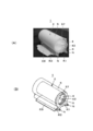
- A) is imaging of the prototype in the state in which the elastic bandage is mounted
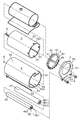
- (B) is the perspective view. It is a disassembled perspective view of a bandage winding tool.
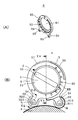
- A) is a perspective view from the reverse direction to FIG. 3 of the outer lid of a bandage winding tool
- (B) is a right view of a bandage winding tool.
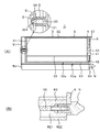
- (A) is a VA-VA cross-sectional view of FIG. 4 (B), and (B) is a VB-VB cross-sectional view of FIG. 4 (B).
- A) is a right side view when inserting an elastic bandage in a bandage winding tool
- (B) is a right side view of the state which rotated the dial from the state of (A) and raised tension.
- a compression pressure measuring device (a device for measuring the pressure of the air pushed out when the sponge set in the sensor portion is compressed) is fixed on a resin having a hardness equivalent to that of the human body.
- tension and compression pressure of the elastic bandage EB there is a correlation between tension and compression pressure of the elastic bandage EB. From this, for example, the tension of the elastic bandage EB for achieving a desired compression pressure can be obtained by obtaining an approximate expression from experimental data by the least squares method. Conversely, the compression pressure can also be determined from the tension. Then, based on the results of this experiment, the inventor considered that if the bandage winding device 1 for adjusting the tension is invented, the elastic bandage EB can be wound uniformly at a desired compression pressure.
- the compression pressure considered to be suitable for compression therapy is 26.7 hPs to 40 hPs (20 to 30 mmHg) shown by a frame in FIG. Therefore, the tension of the elastic bandage EB suitable for compression therapy is about 6 N to about 13 N from FIG.
- the inventor also conducted a tensile test for tension and elongation of the elastic bandage EB. As a result, it has been found that the film stretches rapidly beyond 20 N, but in proportion to the tension at about 6 N to about 13 N suitable for compression therapy.
- the inventor also conducted a tensile cycle test. As a result, the relationship between tension and elongation of the elastic bandage EB did not change even if tension was repeated. From this experimental result, it was found that the elastic bandage EB can be reused with the bandage winding device 1. From the above experimental results, the inventor invented a bandage winding device.
- the bandage winding device 1 of the present embodiment is configured to include a bandage receiving portion 2 for receiving the elastic bandage EB, and a tension adjusting portion for adjusting the tension for pulling out the elastic bandage EB from the bandage receiving portion 2. More specifically, the bandage winding device 1 includes a bandage housing portion 2 which also serves as a tension adjustment portion, a first roller R1, a second roller R2, and a nut N.
- the bandage housing portion 2 includes an inner case 3, an inner lid 4, an outer case 5, an outer lid 6, a coil spring S, and an E-type snap ring E.
- FIG. 6 is a perspective view of the inner lid 4, the outer lid 6 and the nut N in order to describe the main part of the present invention.
- the inner case 3 is made of a cup-shaped synthetic resin formed by injection molding and comprises a circular bottom wall 31 and a cylindrical peripheral wall 32. To accommodate.
- the peripheral wall 32 is provided with a slit-like first outlet 33 through which the elastic bandage EB is pulled out. And as shown in FIG. 3, the four recessed parts 34 for engaging with the inner cover 4 are notched by the opening side of the surrounding wall 32.
- a metal connecting shaft 35 for connecting with the outer case 2 is fixed by an insert toward the outside.
- the connection shaft 35 is formed with a groove 351 in which an E-shaped retaining ring (generally called C ring) E is inserted.
- C ring E-shaped retaining ring
- the inner lid 4 is a lid for closing the inner case 3 as shown in FIG. 3 and is a synthetic resin in the shape of a top hat having a low height.
- the inner lid 4 includes a petri dish-shaped (shallow cup-shaped) insertion portion 41 to be inserted into the peripheral wall 32 of the inner case 3 and a disk-shaped abutment portion 42 which stops the insertion of the insertion portion 41 in the middle.
- the outer diameter of the contact portion 42 is the same as the outer diameter of the peripheral wall 32 of the inner case 3.
- a convex portion 44 to be engaged with the concave portion 34 of the peripheral wall 32 of the inner case 3 is formed.
- a knob 43 for rotating the inner lid 4 is formed on the outer lid 6 side of the insertion portion 41. Further, on the contact portion 42, a plurality of right triangle claws 45 are formed toward the outer lid 6 so as to contact the outer lid 6 to stop the rotation.
- the outer case 5 is made of a cup-shaped synthetic resin formed by injection molding, and includes a circular bottom wall 51 and a cylindrical peripheral wall 52.
- the inner lid 4 is accommodated.
- the peripheral wall 52 is provided with a slit-like second outlet 53 through which the elastic bandage EB pulled out from the first outlet 33 of the inner case 3 is pulled out.
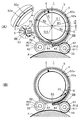
- FIG. 6A is a view showing the rotational position of the inner case 3 in which the position of the first outlet 33 of the inner case 3 matches the position of the second outlet 53 of the outer case 5.
- the gap G between the outer periphery 32a of the peripheral wall 32 of the inner case 3 and the inner periphery 52a of the peripheral wall 52 of the outer case 5 is different between the left side and the right side.
- the gap G of about half a circumference (left side) in the clockwise direction is a concentric fitting gap (R2-R1).
- the gap G between the outer periphery 32a of the peripheral wall 32 of the inner case 3 and the inner periphery 52a of the peripheral wall 52 of the outer case 5 gradually increases to about half a circumference as going backward from the second outlet 53 in the counterclockwise direction. It has become narrow.
- the outer case 5 is provided with an axial hole 56 into which the connecting shaft 35 of the inner case 3 is fitted at the center of the bottom wall 51.
- the shaft hole 56 is formed to be recessed inside the cylinder of the peripheral wall 52.
- a key-like locking piece 57 which is locked by the outer lid 6 is formed to extend to the peripheral wall 52.
- the outer lid 6 is a lid for preventing the inner case 3 and the inner lid 4 stored in the outer case 5 from coming off, and is made of a ring-shaped synthetic resin in which a knob hole 61 into which the knob 43 of the inner lid 4 is fitted is opened. is there.
- the scale 62 (1" to "8" in FIG. ) Is formed by printing or engraving of a mold.
- the scales 62 used for tension adjustment are attached at substantially equal intervals. This is due to the result of the tension test conducted on the elastic bandage EB conducted by the inventor described above. That is, as a result of this test, it is found that the film stretches rapidly when it exceeds 20 N, but in about 6 N to about 13 N suitable for compression therapy, it extends in proportion to the tension. Were placed at substantially equal intervals.
- a plurality of claws 63 of a right triangle that engages in the rotational direction of the inner lid 4 are formed on the side of the inner lid 4 of the outer lid 6.
- the outer periphery of the outer cover 6 has substantially the same shape as the outer periphery of the bottom wall 51 of the outer case 5.
- the outer lid 6 includes two arms 64 extending outward from the center. The arm 64 is provided with a nut hole 65 into which a nut N is fitted. Further, the outer cover 6 is engaged with the locking piece 57 of the outer case 5 by rotating clockwise. A notch 66 is provided on the outer periphery of the outer lid 6 to enable this rotation.
- the first roller R1 is composed of a pipe-shaped synthetic resin core R11 having an axial hole R111 fitted into the roller shaft 55 of the outer case 5, and a skin R12 of elastic material covering the arc surface of the core R11.
- the second roller R2 is also the same as the first roller R1, and a core R21 of a pipe-shaped synthetic resin having an axial hole R211 fitted into the roller shaft 55 of the outer case 5 and a skin of an elastic material covering the arc surface of R21. It consists of R22.
- the skins R12 and R22 of the first roller R1 and the second roller R2 are made of an elastic material that does not slip against the elastic bandage EB. Further, the gaps from the skins R12, R22 of the first roller R1 and the second roller R2 to the outer periphery of the bottom wall 51 of the outer case 5 are all the same, and have a size through which the elastic bandage EB passes.
- first roller R1 and the second roller R2 have the same shape, the gap G between the outer periphery 32a of the inner case 3 and the inner periphery 52a of the outer case 5 of these two goes deep from the second outlet 53
- the first roller R1 is on the side (right side in FIG. 6A) which is gradually narrowed in accordance with the above, and the second roller R2 is on the other side (left side in FIG. 6A).
- the two nuts N having female threads are screwed into the roller shaft 55 of the outer case 5 to hold the first roller R1, the second roller R2 and the outer lid 6.
- the user inserts the inner case 3 into the outer case 5 with the coil spring S fitted to the connection shaft 35 of the inner case 3, and inserts the connection shaft 35 of the inner case 3 into the axial hole 56 of the outer case 5.
- the E-shaped retaining ring E is inserted into the groove 351 of the connecting shaft 35 using its dedicated jig (step 1).
- the inner case 3 is pivotally supported by the outer case 5.
- the inner case 3 slides backward.
- the engagement between the claw 45 of the inner lid 4 and the claw 63 of the outer lid 6 can be released.
- the user inserts the first roller R1 and the second roller R2 into the roller shaft 55 of the outer case 5 (step 2).
- the user rotates the inner case 3 so that the first outlet 33 of the inner case 3 matches the second outlet 53 of the outer case 5 as shown in FIG. 6A (step 3).
- the user passes the elastic bandage EB through the first outlet 33 and the second outlet 53, with the rotation in the counterclockwise direction when the bandage is fed out, and the first roller R1 on the right side. And the outer case 5 and insert the elastic bandage EB into the inner case 3 (step 4).
- the user fits the inner lid 4 into the inner case 3 by fitting the convex portion 44 of the inner lid 4 into the recess 34 of the inner case 3 (step 5).
- the user pushes the inner lid 4 in a counterclockwise direction so that the notch 66 of the outer lid 6 is positioned in the locking piece 57 of the outer case 5, and presses the outer lid 6 into the outer case 5.
- the outer cover 6 is fitted into the locking piece 57 of the outer case 5 (step 6).
- the user screws the two nuts N into the roller shaft 55 of the outer case 5 (step 7).
- the inner lid 4 is prevented from rotating clockwise due to the engagement between the claws 45 of the inner lid 4 and the claws 63 of the outer lid 6.
- the inner case 3 and the inner lid 4 are automatically pushed backward against the pressure of the coil spring S by the slippage of the inclined surfaces of the claws 45, 63. Therefore, when the user turns the knob 43 counterclockwise, the inner lid 4 and the inner case 3 rotate.
- the bandage winding device 1 is in an initial state in which the first outlet 33 of the inner case 3 matches the second outlet 53 of the outer case 5.
- the knob 43 of the inner lid 4 is at the position of “1” of the scale 62 of the outer lid 6.
- the knob 43 is rotated counterclockwise to move it to the position shown in FIG. 6 (B) in order to obtain the tension (the desired compression pressure) desired by the user.
- the knob 43 of the inner lid 4 is at the position "4" of the scale 62 of the outer lid 6 (FIG. 4 (B)).
- the tension adjustment portion of the bandage winding device 1 is a compact tension adjustment mechanism.
- this gap is narrowed toward the back, a large change in tension occurs at a small rotation angle. Therefore, the tension adjustment portion of the bandage winding device 1 is compact and enables a wide range of tension adjustment.
- the user may rotate the knob 43 counterclockwise, and when it is desired to lower the tension, the user depresses the knob 43 clockwise. You can rotate it.
- the state of use of the elastic bandage EB will be described with reference to FIGS. 4 (B) and 6 (B).
- the elastic bandage EB is wound around the affected area (here, the thigh) F with the knob 43 of the inner lid 4 at the position "4" of the scale 62 of the outer lid 6. It is a figure which shows the state which is.
- the position where the knob 43 is “4” of the scale 62 is, for example, the compression pressure when the elastic bandage EB is wound with 50% overlap on the thigh (F) for compression therapy,
- the tension of the elastic bandage EB pulled out from the bandage winding tool 1 changes.
- the position of the scale 62 is adjusted to obtain a desired tension.
- the compression pressure changes if the overlapping degree of the elastic bandages EB is changed.
- the position of the scale 62 is adjusted so as to obtain a tension to obtain a desired compression pressure.
- the bandage winding device of the present invention is not limited to the one used for the elastic bandage EB described in the present embodiment, and can be used also for general bandages.
- the compression pressure may be altered.
- the position of the scale 62 is adjusted so as to obtain a tension to obtain a desired compression pressure.
- the bandage winding device 1 can adjust the tension depending on the situation, a desired compression pressure can be obtained.
- the elastic bandage EB housed in the inner case 3 goes counterclockwise toward the first outlet 33, and makes a U-turn at the first outlet 33 and then clockwise toward the second outlet 53. Head. Then, the elastic bandage EB makes a U-turn at the second outlet 53 and travels counterclockwise toward the first roller R1, and performs a U-turn at the first roller R1 toward the second roller R2. Then, the user rotates the bandage winding device 1 while applying the first roller R1 and the second roller R2 to the affected area F, whereby the elastic bandage EB is wound around the affected area.
- the elastic bandage EB can be wound while pressing against the affected area and rolling while rolling on the first roller R1 provided with the elastic material and non-slippery surface R12, it is possible to hold the tension in the entire width direction of the elastic bandage EB and wind it. it can.
- the second roller R2 provided with the elastic material and non-slippery surface R22 can stabilize the inclination of the first roller R1 by winding the second roller R2 while contacting the affected part.
- the elastic bandage EB extended and drawn out from the first holding roller R1 with a predetermined tension is sandwiched between the second roller R2 and the affected area F, it can maintain an extended state and maintain a predetermined tension. .
- the bandage winding device 1 of the present invention can realize an optimum compression pressure by providing a tension adjustment portion for adjusting tension, and tension for an elastic bandage EB used even by a non-expert person.
- the elastic bandage EB can be wound around the affected area so that the pressure is a predetermined compression pressure.
- the tension adjusting portion in the present embodiment is a mechanism capable of adjusting the length of the elastic bandage EB from the first outlet 33 to the second outlet 53, and is an inner case 3 which is the bandage accommodating portion 2. It comprises a lid 4, an outer case 5, an outer lid 6, a coil spring S and an E-shaped retaining ring E. That is, in the present embodiment, the bandage housing portion 2 also serves as a tension adjustment portion.
- the bandage winding device is not limited to such a configuration, and for example, the configuration may be such that a tension adjustment portion is attached in contact with the bandage housing portion 2. In the case of such a bandage winding device, the elastic bandage EB pulled out from the bandage containing portion is adjusted in tension drawn by the tension adjustment portion.
- the user brings the first outlet 33 of the inner case 3 to the second outlet 53 of the outer case 5 with the knob 43 of the inner lid 4 at the position “1” of the scale 62 of the outer lid 6.
- the user pivots and removes the two nuts N, and then rotates the outer cover 6 counterclockwise.
- the user unscrews the outer lid 6 from the locking piece 57 of the outer case 5 and finally removes the elastic bandage EB from the inner case 3.
- 1st roller R1 and 2nd roller R2 of the above-mentioned embodiment were the same diameter, they may be different diameters. By changing the diameter of the roller, various diameters of the affected area can be accommodated. Also, the position of the roller can be changed to accommodate different diameters of the affected area.
- the present application is based on the experimental results shown in FIG. 1 and realizes that an optimum compression pressure can be realized by appropriately adjusting the tension for pulling out the bandage, and the present invention is limited to the tension adjustment portion of the above embodiment. Absent.
- the present application can be applied to a bandage winding device provided with a tension adjustment portion that adjusts tension for pulling out the elastic bandage from the bandage containing portion that accommodates the bandage.
- friction there are various conceivable methods of friction to the adjustable bandage other than the embodiments described above.
Landscapes
- Health & Medical Sciences (AREA)
- Life Sciences & Earth Sciences (AREA)
- Engineering & Computer Science (AREA)
- Biomedical Technology (AREA)
- Heart & Thoracic Surgery (AREA)
- Vascular Medicine (AREA)
- Epidemiology (AREA)
- Animal Behavior & Ethology (AREA)
- General Health & Medical Sciences (AREA)
- Public Health (AREA)
- Veterinary Medicine (AREA)
- Surgical Instruments (AREA)
- Massaging Devices (AREA)
Abstract
[Problème] Les bandages élastiques sont enroulés autour d'une partie affectée d'un patient par une infirmière. Cette action est effectuée en fonction du toucher et du niveau de compétence de l'infirmière individuelle et, par conséquent, il n'était pas clair comment appliquer le bandage à une compression appropriée. Par conséquent, il était difficile d'enrouler le bandage élastique autour de la partie affectée au degré approprié de compression. Un objectif de la présente invention est de fournir un instrument d'enroulement de bandage ayant une fonction de réglage de tension et pouvant enrouler un bandage élastique autour de la partie affectée de telle sorte que la tension du bandage atteint une compression prescrite même lorsqu'elle est appliquée par une personne inexpérimentée en bandage. [Solution] La solution selon l'invention porte sur un instrument d'enroulement de bandage comprenant : une partie de logement de bandage (2) pour loger un bandage élastique (BE); et une partie de réglage de tension pour ajuster la tension à laquelle le bandage élastique (BE) est tiré de la partie de logement de bandage (2).
Applications Claiming Priority (2)
| Application Number | Priority Date | Filing Date | Title |
|---|---|---|---|
| JP2017-176440 | 2017-09-14 | ||
| JP2017176440A JP7043694B2 (ja) | 2017-09-14 | 2017-09-14 | 包帯巻き具 |
Publications (1)
| Publication Number | Publication Date |
|---|---|
| WO2019054369A1 true WO2019054369A1 (fr) | 2019-03-21 |
Family
ID=65724015
Family Applications (1)
| Application Number | Title | Priority Date | Filing Date |
|---|---|---|---|
| PCT/JP2018/033628 WO2019054369A1 (fr) | 2017-09-14 | 2018-09-11 | Instrument d'enroulement de bandage |
Country Status (2)
| Country | Link |
|---|---|
| JP (1) | JP7043694B2 (fr) |
| WO (1) | WO2019054369A1 (fr) |
Citations (3)
| Publication number | Priority date | Publication date | Assignee | Title |
|---|---|---|---|---|
| FR737708A (fr) * | 1931-04-14 | 1932-12-15 | Distributeur d'ouate | |
| GB2184026A (en) * | 1985-12-13 | 1987-06-17 | Clutsom Penn Int | Applicator for a compression bandage |
| US5065865A (en) * | 1990-04-17 | 1991-11-19 | Doorenbos Daryl E | Pressure-regulated bandage applicator |
Family Cites Families (4)
| Publication number | Priority date | Publication date | Assignee | Title |
|---|---|---|---|---|
| JP2589427Y2 (ja) * | 1992-03-31 | 1999-01-27 | ニチバン株式会社 | テープ類のケース |
| JP2004209194A (ja) * | 2003-01-07 | 2004-07-29 | Naoko Uezono | 包帯保管ケース |
| WO2010044711A2 (fr) * | 2008-10-17 | 2010-04-22 | Avramenko Anton | Dispositif d’application et de stockage de matériel de pansement sous forme de bandage |
| CN203953974U (zh) * | 2014-08-02 | 2014-11-26 | 杨丽丽 | 一种绷带包装盒 |
-
2017
- 2017-09-14 JP JP2017176440A patent/JP7043694B2/ja active Active
-
2018
- 2018-09-11 WO PCT/JP2018/033628 patent/WO2019054369A1/fr active Application Filing
Patent Citations (3)
| Publication number | Priority date | Publication date | Assignee | Title |
|---|---|---|---|---|
| FR737708A (fr) * | 1931-04-14 | 1932-12-15 | Distributeur d'ouate | |
| GB2184026A (en) * | 1985-12-13 | 1987-06-17 | Clutsom Penn Int | Applicator for a compression bandage |
| US5065865A (en) * | 1990-04-17 | 1991-11-19 | Doorenbos Daryl E | Pressure-regulated bandage applicator |
Also Published As
| Publication number | Publication date |
|---|---|
| JP2019050989A (ja) | 2019-04-04 |
| JP7043694B2 (ja) | 2022-03-30 |
Similar Documents
| Publication | Publication Date | Title |
|---|---|---|
| EP1009355B1 (fr) | Dispositif de mise sous pression des membres | |
| US9033906B2 (en) | Therapeutic compression apparatus | |
| US20050026912A1 (en) | Method of treating restless leg syndrome | |
| US20210186797A1 (en) | Medical pressure therapy device and components thereof | |
| KR20180037250A (ko) | 만곡된 유연한 마사지 롤러 | |
| JP6955875B2 (ja) | 包帯巻き具 | |
| EP1453424B1 (fr) | Dispositif pour evacuer le sang hors d'un membre | |
| CN107981965A (zh) | 一种眼睑按摩器 | |
| US5178627A (en) | Medical device for use in the treatment of hemorrhoids | |
| US3994289A (en) | Acupressure instrument | |
| KR102584800B1 (ko) | 의료용 혈류 개선을 위한 가압 장치 및 그 구성요소 | |
| US11110021B2 (en) | Medical pressure therapy device and components thereof | |
| US11259985B2 (en) | Medical pressure therapy device and components thereof | |
| CN208838425U (zh) | 一种医疗外科用换药护理支撑架 | |
| WO2019054369A1 (fr) | Instrument d'enroulement de bandage | |
| KR101617663B1 (ko) | 마사지 롤러 | |
| JP2008054853A (ja) | 四肢体幹に圧迫力を与えるための医療具 | |
| KR101573852B1 (ko) | 지혈대 및 이를 포함한 지혈 기구 | |
| Struckmann et al. | Venous muscle pump improvement by low compression elastic stockings | |
| KR20100000423A (ko) | 착용형 지압기 | |
| JP2022071257A (ja) | 包帯巻き具 | |
| Verzwyvelt et al. | Optimising application of a two-layer compression bandage using continuous, multi-point sub-bandage pressure monitoring in healthy volunteers. | |
| KR20170108439A (ko) | 배혈 및 압박장치 | |
| RU40873U1 (ru) | Устройство для удержания спицы при переломе костей | |
| KR20200063758A (ko) | 쿨팩을 이용한 얼굴 마사지 기구 |
Legal Events
| Date | Code | Title | Description |
|---|---|---|---|
| 121 | Ep: the epo has been informed by wipo that ep was designated in this application |
Ref document number: 18857277 Country of ref document: EP Kind code of ref document: A1 |
|
| NENP | Non-entry into the national phase |
Ref country code: DE |
|
| 122 | Ep: pct application non-entry in european phase |
Ref document number: 18857277 Country of ref document: EP Kind code of ref document: A1 |