WO2019049341A1 - 電力制御装置、および、電力制御装置の制御方法 - Google Patents
電力制御装置、および、電力制御装置の制御方法 Download PDFInfo
- Publication number
- WO2019049341A1 WO2019049341A1 PCT/JP2017/032579 JP2017032579W WO2019049341A1 WO 2019049341 A1 WO2019049341 A1 WO 2019049341A1 JP 2017032579 W JP2017032579 W JP 2017032579W WO 2019049341 A1 WO2019049341 A1 WO 2019049341A1
- Authority
- WO
- WIPO (PCT)
- Prior art keywords
- terminal
- battery
- voltage
- positive
- negative
- Prior art date
- Legal status (The legal status is an assumption and is not a legal conclusion. Google has not performed a legal analysis and makes no representation as to the accuracy of the status listed.)
- Ceased
Links
Images


Classifications
-
- H—ELECTRICITY
- H01—ELECTRIC ELEMENTS
- H01M—PROCESSES OR MEANS, e.g. BATTERIES, FOR THE DIRECT CONVERSION OF CHEMICAL ENERGY INTO ELECTRICAL ENERGY
- H01M10/00—Secondary cells; Manufacture thereof
- H01M10/42—Methods or arrangements for servicing or maintenance of secondary cells or secondary half-cells
- H01M10/48—Accumulators combined with arrangements for measuring, testing or indicating the condition of cells, e.g. the level or density of the electrolyte
-
- H—ELECTRICITY
- H02—GENERATION; CONVERSION OR DISTRIBUTION OF ELECTRIC POWER
- H02J—ELECTRIC POWER NETWORKS; CIRCUIT ARRANGEMENTS OR SYSTEMS FOR SUPPLYING OR DISTRIBUTING ELECTRIC POWER; SYSTEMS FOR STORING ELECTRIC ENERGY
- H02J7/00—Circuit arrangements for charging or discharging batteries or for supplying loads from batteries
-
- H—ELECTRICITY
- H02—GENERATION; CONVERSION OR DISTRIBUTION OF ELECTRIC POWER
- H02J—ELECTRIC POWER NETWORKS; CIRCUIT ARRANGEMENTS OR SYSTEMS FOR SUPPLYING OR DISTRIBUTING ELECTRIC POWER; SYSTEMS FOR STORING ELECTRIC ENERGY
- H02J7/00—Circuit arrangements for charging or discharging batteries or for supplying loads from batteries
- H02J7/02—Circuit arrangements for charging or discharging batteries or for supplying loads from batteries for charging batteries from AC mains by converters
-
- Y—GENERAL TAGGING OF NEW TECHNOLOGICAL DEVELOPMENTS; GENERAL TAGGING OF CROSS-SECTIONAL TECHNOLOGIES SPANNING OVER SEVERAL SECTIONS OF THE IPC; TECHNICAL SUBJECTS COVERED BY FORMER USPC CROSS-REFERENCE ART COLLECTIONS [XRACs] AND DIGESTS
- Y02—TECHNOLOGIES OR APPLICATIONS FOR MITIGATION OR ADAPTATION AGAINST CLIMATE CHANGE
- Y02E—REDUCTION OF GREENHOUSE GAS [GHG] EMISSIONS, RELATED TO ENERGY GENERATION, TRANSMISSION OR DISTRIBUTION
- Y02E60/00—Enabling technologies; Technologies with a potential or indirect contribution to GHG emissions mitigation
- Y02E60/10—Energy storage using batteries
Definitions
- the present invention relates to a power control device and a control method of the power control device.
- an electric two-wheeled vehicle using a motor as a power source is known.
- this conventional electric motorcycle one battery is used as a power source.
- Patent Document 1 when one of the plurality of batteries connected in parallel fails, there is a problem that the necessary power can not be supplied (see Patent Document 1 and Patent Document 2).
- an object of the present invention is to provide a power control apparatus capable of supplying necessary power even when one of a plurality of batteries fails.
- a power control apparatus is: A first positive battery terminal to which the positive electrode of the first battery is connectable, and a first negative battery terminal to which the negative electrode of the first battery is connectable; A second positive battery terminal to which the positive electrode of the second battery is connectable, and a second negative battery terminal to which the negative electrode of the second battery is connectable; A first charging terminal connected to the high potential side output of the charger, to which a voltage on the high potential side of the charger is applied; A second charge terminal connected to the low potential side output of the charger and to which a low potential side voltage of the charger is applied; A first drive voltage terminal and a second drive voltage terminal; Positive voltage terminal, A negative voltage terminal electrically connected to the first negative battery terminal, the second negative battery terminal, and the second charging terminal; A first contactor having one end connected to the first positive battery terminal and the other end connected to the positive voltage terminal; A second contactor having one end connected to the positive voltage terminal and the other end connected to the second positive battery terminal; A rectifying element having a first node connected to
- the drive control unit A motor drive voltage is generated from a voltage between the first drive voltage terminal and the second drive voltage terminal, and the motor is driven by the motor drive voltage.
- the down regulator is characterized in that it does not have an insulating configuration to prevent an electric shock.
- the second battery connected to the second positive battery terminal and the second negative battery terminal is broken and the first battery terminal connected to the first positive battery terminal and the first negative battery terminal
- the drive control unit The first contactor is controlled to be ON, the second contactor is controlled to be OFF, and the voltage between the positive voltage terminal and the negative voltage terminal is boosted, and the boosted voltage is boosted to the first voltage. Controlling the up-converter so as to apply between the drive voltage terminal of the second drive voltage terminal and the second drive voltage terminal to discharge only the first battery, the first drive voltage terminal and the second drive voltage terminal. A voltage of a specified value set in advance is applied between the drive voltage terminal and the drive voltage terminal.
- the first battery connected to the first positive battery terminal and the first negative battery terminal fails and the second battery connected to the second positive battery terminal and the second negative battery terminal
- the drive control unit The first contactor is controlled to be off, the second contactor is controlled to be on, and the voltage between the positive voltage terminal and the negative voltage terminal is boosted, and the boosted voltage is boosted to the first voltage.
- Controlling the up-converter so as to apply between the drive voltage terminal of the second drive voltage terminal and the second drive voltage terminal to discharge only the second battery, the first drive voltage terminal and the second drive voltage terminal.
- a voltage of the specified value is applied between the drive voltage terminal and the drive voltage terminal.
- the drive control unit The first contactor is controlled to be on, and the second contactor is controlled to be charged so that the charging voltage is supplied from the charger to the first battery and the second battery.
- the configuration of the second battery is the same as the configuration of the first battery, A first battery voltage output from the first battery is the same as a second battery voltage output from the second battery.
- a reference battery terminal connected to a positive electrode of a reference battery and supplied with a reference voltage; A reference charging terminal to which the charger can be connected; And a switch circuit having one end connected to the reference battery terminal and the other end connected to the reference charging terminal, the first battery power supply terminal, and the drive control unit power supply terminal.
- the first battery is First charging a voltage between the first positive battery terminal and the first negative battery terminal or discharging a charging voltage between the first positive battery terminal and the first negative battery terminal Cells, and A first management unit activated by the reference voltage supplied to the first battery power supply terminal, monitoring a state of the first cell, and outputting information on the state of the first cell; Equipped
- the second battery is Second charging the voltage between the second positive battery terminal and the second negative battery terminal or discharging the charging voltage between the second positive battery terminal and the second negative battery terminal Cells, and It starts with the 1st starting voltage supplied from the said drive control part, or the 2nd starting voltage supplied from the said charger, monitors the state of the said 2nd cell, and the information regarding the state of the said 2nd cell And a second management unit that outputs the
- the drive control unit By communicating with the first management unit, it is determined whether the first battery is broken or not. By communicating with the second management unit, it is determined whether or not the second battery is broken.
- the drive control unit A capacitor connected between the first drive voltage terminal and the second drive voltage terminal; A voltage is supplied between the first drive voltage terminal and the second drive voltage terminal, and a motor drive voltage is output to the motor to further drive a bridge circuit for driving the motor. .
- the power control device is mounted on an electric two-wheeled vehicle, the motor is connected to a wheel of the electric two-wheeled vehicle, and the drive control unit controls the rotation of the wheel by controlling the driving of the motor. Do.
- the reference battery is a lead battery
- the first and second batteries are lithium ion batteries.
- the reference battery may be charged by a voltage output from the down regulator.
- a control method of a power control apparatus The first positive battery terminal to which the positive electrode of the first battery can be connected, the first negative battery terminal to which the negative electrode of the first battery can be connected, and the positive electrode of the second battery A second positive battery terminal that can be connected, and a second negative battery terminal that can be connected to the negative electrode of the second battery, and an output on the high potential side of a charger are connected, the charging A first charging terminal to which the high potential side voltage of the charger is applied, and a second charging terminal to which the low potential side output of the charger is connected and to which the low potential side voltage of the charger is applied Electrically connected to a first drive voltage terminal and a second drive voltage terminal, a positive voltage terminal, the first negative battery terminal, the second negative battery terminal and the second charging terminal A negative voltage terminal and one end connected to the first positive battery terminal, A first contactor whose end is connected to the positive voltage terminal, a second contactor whose one end is connected to the positive voltage terminal and whose other end is connected
- a power control apparatus is a first positive battery terminal to which a positive electrode of a first battery is connectable, and a first negative terminal to which a negative electrode of the first battery is connectable.
- the output of the potential side is connected, the first charging terminal to which the high potential side voltage of the charger is applied, and the output of the low potential side of the charger are connected, the voltage of the low potential side of the charger is applied
- the first contactor whose other end is connected to the positive voltage terminal
- the second contactor whose one end is connected to the positive voltage terminal and the other end is connected to the second positive battery terminal
- the first node (anode) Is connected to the first charging terminal
- the second node (cathode) is connected to the second positive battery terminal and the other end of the second contactor to prevent reverse current flow, a positive voltage terminal and a negative terminal.
- An up converter for boosting a voltage between the first and second drive voltages and boosting the boosted voltage between the first and second drive voltages, and a voltage between the positive and negative voltage terminals.
- the first positive battery is obtained by controlling the first contactor and the second contactor while stepping down the voltage and controlling the down converter outputting the load terminal to which the load is connected and the up converter and the down regulator. Controlling an electrical circuit connection between a first battery connected to the secondary battery terminal and the first negative battery terminal, and a second battery connected to the second positive battery terminal and the second negative battery terminal And a drive control unit that controls charging and discharging of the first battery and the second battery.
- the second battery connected to the second positive battery terminal and the second negative battery terminal may fail and only the first battery connected to the first positive battery terminal and the first negative battery terminal.
- the drive control unit controls the first contactor to turn on and turns off the second contactor. Control the voltage between the positive voltage terminal and the negative voltage terminal, and apply the boosted voltage between the first drive voltage terminal and the second drive voltage terminal. Is controlled to discharge only the first battery to apply a voltage of a prescribed value between the first drive voltage terminal and the second drive voltage terminal.
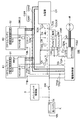
- FIG. 1 is a diagram showing an example of the configuration of a power control apparatus 100 according to the embodiment.
- FIG. 2 is a diagram for explaining an example of an operation at the time of charging of the first and second batteries B1 and B2 of the power control apparatus 100 shown in FIG.
- FIG. 3 is a diagram for explaining an example of the operation at the time of discharging of the first and second batteries B1 and B2 of the power control apparatus 100 shown in FIG. 1 (during motor driving).
- FIG. 4 is a diagram for describing an example of the operation of the power control apparatus 100 shown in FIG. 1 when the second battery B2 fails and only the first battery B1 is discharged (motor drive). .
- FIG. 1 is a diagram showing an example of the configuration of a power control apparatus 100 according to the embodiment.
- the mobile battery is two pieces (1st, 2nd battery B1, B2) of the minimum unit is described, when three or more mobile batteries are connected Is also described similarly.
- the power control apparatus 100 includes a reference battery terminal TK, a reference charging terminal TCS, a first positive battery terminal T1P, and a first negative battery terminal T1N.
- the power control device 100 is, for example, loaded on an electric two-wheeled vehicle (vehicle).
- vehicle vehicle
- the motor M is connected to the wheels of the electric motorcycle.
- the power control apparatus 100 is started by the voltage of a reference battery (lead battery) K. Then, the power control apparatus 100 generates a motor drive voltage from the voltages of the first and second batteries (Li batteries) B1 and B2, and drives the motor M with this motor drive voltage. Then, the power control device 100 controls the rotation of the wheel by controlling the drive of the motor M.
- a reference battery lead battery
- the reference battery terminal TK is connected to the positive electrode of the reference battery K, and is supplied with a reference voltage.
- the reference battery K is, for example, a lead battery.
- the first charge terminal TCP is connected to the output on the high potential side of the charger CH, and the voltage on the high potential side of the charger CH is applied.
- the second charge terminal TCN is connected to the low potential side output of the charger CH, and a voltage on the low potential side of the charger CH is applied.
- the reference charging terminal TCS is connectable to the charger CH, and is electrically connected to the first battery power supply terminal T1B and the drive control unit power supply terminal TPS1.
- the charger CH may be connected as long as at least the first and second batteries B1 and B2 are charged, and the electric power control device mounted on the electric motorcycle when the electric motorcycle is traveling as described above. It may be disconnected from 100 (each terminal TCN, TCP, TCOUT, TCS).
- first drive voltage terminal TDP is electrically connected to one end of the capacitor Z of the drive control unit PDU.
- the second drive voltage terminal TDN is electrically connected to the other end of the capacitor Z of the drive control unit PDU.
- the drive control unit power supply terminal TG is electrically connected to the reference charging terminal TCS.
- the first start-up voltage terminal TPS2 is connected to the drive control unit PDU and is electrically connected to the second battery power supply terminal T2B.
- the charger CH can be connected to the second start voltage terminal TCOUT, and the second start voltage terminal TCOUT is electrically connected to the second battery power supply terminal T2B.
- first battery B1 can be connected to the first battery power supply terminal T1B, and the first battery power supply terminal T1B is connected to the other end of the switch circuit SW and the reference charging terminal TCS.
- the second battery power supply terminal T2B is connectable to the second battery B2, and is connected to the first and second start voltage terminals TPS2 and TCOUT.
- the first and second batteries B1 and B2 which are mobile batteries are, for example, lithium ion batteries. That is, the battery voltage (48 V) output by the first and second batteries B1 and B2 is set to be higher than the battery voltage (12 V) which is the reference voltage output by the reference battery K.
- the positive terminal of the first battery B1 described above can be connected to the first positive battery terminal T1P.
- the first negative battery terminal T1N is connectable to the negative electrode of the first battery B1.
- the positive voltage terminal TAP is electrically connected to the positive input of the up converter AP and the down regulator DR.
- the negative voltage terminal TAN is electrically connected to the negative input of the up converter AP and the down regulator DR, the first negative battery terminal T1N, the second negative battery terminal T2N, and the second charging terminal TCN. There is.
- the first battery B1 includes a first cell (a plurality of lithium ion batteries connected in series) S1 and a first management unit BMU1.
- the first cell S1 charges the voltage between the first positive battery terminal T1P and the first negative battery terminal T1N, or the first positive battery terminal T1P and the first negative battery terminal T1N. And discharge the charge voltage between them.
- the first management unit BMU1 is activated by the reference voltage supplied to the first battery power supply terminal T1B, and the state (first cell S1) of the first cell S1 (that is, the first battery B1).
- the identification information of the first battery B1 is set as the initial identification information.
- the first battery B1 When the first battery B1 is removed from the power control apparatus 100 (for example, each of the terminals T1P, T1N, and T1B), its identification information is reset to the initial identification information.
- the first management unit BMU1 forcibly contacts the first management contactor T1 for stopping charging / discharging of the first cell S1 according to the state (fault etc.) of the first cell S1.
- the positive terminal of the second battery B2 described above can be connected to the second positive battery terminal T2P.
- the second negative battery terminal T2N can be connected to the negative electrode of the second battery B2.
- the second battery B2 includes a second cell (a plurality of lithium ion batteries connected in series) S2 and a second management unit BMU2.
- the second cell S2 charges the voltage between the second positive battery terminal T2P and the second negative battery terminal T2N, or the second positive battery terminal T2P and the second negative battery terminal T2N. And discharge the charge voltage between them.
- the second management unit BMU2 is supplied with the first start voltage supplied from the drive control unit PDU or the second start voltage supplied from the charger CH (that is, supplied to the second battery power supply terminal T2B).
- the second cell S2 ie, the second battery B2
- the temperature of the cell S2, the current of the second cell S2, etc. is monitored, and information on the state of the second cell S2 (ie, the second battery B2) is output.
- the identification information of the second battery B2 is set to the same initial identification information as the identification information of the first battery B1.
- the second management unit MBU2 makes the second management contactor T2 for forcibly stopping the charge / discharge of the second cell S2 according to the state (fault etc.) of the second cell S2. Prepare.
- the identification information thereof is reset to the initial identification information.
- the configuration of the second battery B2 is the same as the configuration of the first battery B1 described above.
- the first battery voltage (48 V) output by the first battery B1 is the same as the second battery voltage (48 V) output by the second battery B2.
- the switch circuit SW has one end connected to the reference battery terminal TK and the other end electrically connected to the reference charging terminal TCS, the first battery power supply terminal T1B, and the drive control unit power supply terminal TPS1.
- the switch circuit SW is configured to supply the reference voltage of the reference battery K to the drive control unit PDU and the first battery B1, for example, by being turned on.
- the switch circuit SW is configured to cut off the supply of the reference voltage of the reference battery K to the drive control unit PDU and the first battery B1 by being turned off.
- the main switch control unit X is supplied with power from the positive electrode of the reference battery K, and controls the switch circuit SW in accordance with the operation (action) of the user.
- the communication line CAN allows the first battery B1 connected to the first positive battery terminal T1P and the first negative battery terminal T1N to communicate with the drive control unit PDU (or the charger CH), and The second battery B2 connected to the positive battery terminal T2P and the second negative battery terminal T2N communicate with the drive control unit PDU (or the charger CH).
- the communication line CAN includes a first communication line CAN1 for the first and second batteries B1 and B2 to transmit data to the drive control unit PDU, a command from the drive control unit PDU or the charger CH, and the like.
- a second communication line CAN2 for transmitting to the second batteries B1 and B2 is provided.
- the down regulator DR is configured to step down and output a voltage between the positive voltage terminal TAP and the negative voltage terminal TAN (voltage output from the first and second batteries B1 and B2).
- the down regulator DR does not have an insulation configuration for preventing electric shock because the input voltage is about 48 V which is relatively low which is output by the first and second batteries B1 and B2. Thereby, the down regulator DR can be miniaturized.
- the down regulator DR is, for example, a DC-DC converter that steps down a voltage between the first drive voltage terminal TDP and the second drive voltage terminal TDN and outputs the voltage to the load terminal TR to which the load Load is connected. It is.
- the reference battery K is charged by the voltage output from the down regulator DR.
- the load Load includes, for example, any of the lights, blinkers, and indicators of the electric motorcycle described above, and other electronic components necessary for traveling the electric motorcycle and the like.
- the reference battery K is charged by the step-down voltage (12 V) output from the down regulator DR.
- first contactor CA is connected to the first positive battery terminal T1P, and the other end is connected to the positive voltage terminal TAP.
- the first contactor CA is controlled to be turned on / off by the drive control unit PDU.
- one end of the second contactor CB is connected to the positive voltage terminal TAP, and the other end is connected to the second positive battery terminal T2P and the second node (cathode) of the rectifying element (diode) DX.
- the second contactor CB is controlled to be turned on / off by the drive control unit PDU.
- the rectifying element DX has a first node (anode) connected to the first charging terminal TCP, and a second node (cathode) connected to the second positive battery terminal T2P and the other end of the second contactor CB. , A diode to prevent the backflow of current.
- the up converter AP boosts the voltage between the positive voltage terminal TAP and the negative voltage terminal TAN, and boosts the boosted voltage between the first drive voltage terminal TDP and the second drive voltage terminal TDN. It is adapted to apply.
- the upconverter AP is configured such that the boosting operation is controlled by the drive control unit PDU.
- the up-converter AP has a function of boosting in only one direction (ie, has no function of boosting in both directions).
- the drive control unit PDU generates a motor drive voltage from the voltages of the first battery B1 and the second battery B2, and drives the motor by this motor drive voltage. It has become.
- the drive control unit PDU controls the rotation of the wheel by controlling the drive of the motor M.
- the drive control unit PDU includes a capacitor Z connected between a first drive voltage terminal TDP and a second drive voltage terminal TDN, and a first drive voltage terminal TDP.
- a voltage (voltage of the capacitor Z) between the second drive voltage terminal TDN and the bridge circuit Y which outputs the motor drive voltage to the motor M to drive the motor M is supplied.
- the drive control unit PDU generates a motor drive voltage by the bridge circuit Y from the voltage between the first drive voltage terminal TDP and the second drive voltage terminal TDN, and drives the motor M with the motor drive voltage. It is supposed to
- the drive control unit PDU includes data including identification information of the first battery B1 connected to the first positive battery terminal T1P and the first negative battery terminal T1N via the communication line CAN, and a second positive Data including identification information of the second battery B2 connected to the battery terminal T1P and the second negative battery terminal T2N is received.
- the drive control unit PDU recognizes the information of the first and second batteries B1 and B2 to control the upconverter AP and the down regulator DR, and also controls the first contactor CA and the second contactor CB.
- the first battery B1 connected to the first positive battery terminal T1P and the first negative battery terminal T1N, and the second positive battery terminal T2P and the second negative battery terminal T1N
- the electric circuit connection with the second battery B2 is controlled, and the charge and discharge of the first battery B1 and the second battery B2 are controlled.
- the drive control unit PDU controls the first contactor CA to be on, and turns on the second contactor CB. Control.
- the drive control unit PDU boosts the voltage (48 V) between the positive voltage terminal TAP and the negative voltage terminal TAN and boosts the boosted voltage (96 V) to the first drive voltage terminal TDP and the second drive.
- the up converter AP is controlled to be applied between it and the voltage terminal TDN.
- the drive control unit PDU discharges the first battery B1 and the second battery B2, and the prescribed value set in advance between the first drive voltage terminal TDP and the second drive voltage terminal TDN. Voltage (96 V) is applied.
- the drive control unit PDU controls the first contactor CA to be on, and controls the second contactor CB to be on. Then, the first battery B1 and the second battery B2 are charged in parallel by the charger CH.
- the charging current is supplied from charger CH to second battery B2 through rectifying element DX, while the charger CH supplies the first battery via rectifying element DX, negative voltage terminal TAN, and positive voltage terminal TAP. Charging current is supplied to battery B1.
- the drive control unit PDU is supplied with the reference voltage of the reference battery K via the switch circuit SW and starts up.
- the drive control unit PDU activates the first battery B1 and communicates via the communication line CAN to set identification information of the first battery B1, and then the second battery B2 is The identification information of the second battery B2 is set to be different from the identification information of the first battery B1 by activating and communicating via the communication line CAN.
- the drive control unit PDU is configured to obtain a plurality of pieces of information from the management units BMU1 and BMU2 via the communication line CAN.
- the drive control unit PDU determines that the state of the first battery B1 is normal or abnormal based on battery information on the state of the first battery B1 and the second battery B2 output from the management units BMU1 and BMU2. It is determined to be (whether it is broken).
- the drive control unit PDU communicates with the first management unit BMU1 via the communication line CAN to determine whether the first battery B1 is out of order. Further, the drive control unit PDU communicates with the second management unit BMU2 via the communication line CAN to determine whether or not the second battery B2 is broken.
- the drive control unit PDU stops the drive function of the motor M, for example, all the transistors of the bridge circuit Y are opened, or the high side or low side transistors are shorted. There is.
- the drive control unit PDU can communicate with the above-described charger CH via the communication line CAN. Then, when the charger CH is connected to the reference charging terminal TCS, the drive control unit PDU supplies the first activation voltage output from the charger CH via the reference charging terminal TCS and the drive control unit power terminal TG. It is supposed to be launched.
- the charger CH also includes data including identification information of the first battery B1 connected to the first positive battery terminal T1P and the first negative battery terminal T1N via the communication line CAN, and the second positive Data including identification information of the second battery B2 connected to the battery terminal T1P and the second negative battery terminal T2N is received.
- the charger CH activates the first battery B1, communicates via the communication line CAN, sets identification information of the first battery B1, and then activates the second battery B2.
- the identification information of the second battery B2 can be set to be different from the identification information of the first battery B1.
- the drive control unit PDU drives the motor M by supplying the voltages of the first battery B1 and the second battery B2 to the motor after setting the identification information of the first and second batteries B2 described above.
- the motor M is driven by a voltage (98 V) in which the first battery B1 and the second battery B2 are connected in series. By driving the motor M, the wheels rotate and the electric two-wheeled vehicle travels.
- the drive control unit PDU sets the identification information of the first and second batteries B1 and B2 as described above.
- the circuit connection is controlled so that the first battery B1 and the second battery B2 are connected in parallel.
- the case of charging the second battery B2 connected to the two positive battery terminals T2P and the second negative battery terminal T2N (charging mode) will be described.
- FIG. 2 is a diagram for explaining an example of an operation at the time of charging of the first and second batteries B1 and B2 of the power control apparatus 100 shown in FIG.
- a first charger battery CN connected to the first charging terminal TCP and the second charging terminal TCN is connected to the first positive battery terminal T1P and the first negative battery terminal T1N.
- the drive control unit PDU controls the first contactor CA to turn on, Control the second contactor CB on.
- the drive control unit PDU charges the first battery B1 and the second battery B2 from the charger CH by supplying a charging voltage.
- FIG. 3 is a diagram for explaining an example of the operation at the time of discharging of the first and second batteries B1 and B2 of the power control apparatus 100 shown in FIG. 1 (during motor driving).
- the drive control unit PDU turns on the first contactor CA. Control to control the second contactor CB on.
- the drive control unit PDU boosts the voltage (48 V) between the positive voltage terminal TAP and the negative voltage terminal TAN and boosts the boosted voltage (96 V) to the first drive voltage terminal TDP and the second drive.
- the up converter AP is controlled to be applied between it and the voltage terminal TDN.
- the drive control unit PDU discharges the first battery B1 and the second battery B2, and the voltage (96 V) of the prescribed value between the first drive voltage terminal TDP and the second drive voltage terminal TDN. ) Is applied.
- the second battery B2 connected to the second positive battery terminal T2P and the second negative battery terminal T2N fails and is connected to the first positive battery terminal T1P and the first negative battery terminal T1N
- a case where a voltage is applied between the first drive voltage terminal TDP and the second drive voltage terminal TDN by discharging only the first battery B1 (fault drive mode) will be described.
- FIG. 4 is a diagram for describing an example of the operation of the power control apparatus 100 shown in FIG. 1 when the second battery B2 fails and only the first battery B1 is discharged (motor drive). .
- the second battery B2 connected to the second battery terminal T2P and the second battery terminal T2N fails and the first battery terminal T1P and the When discharging only the first battery B1 connected to the negative battery terminal T1N of 1 and applying a voltage between the first drive voltage terminal TDP and the second drive voltage terminal TDN, the first contactor Control CA on and control second contactor CB on.
- the drive control unit PDU may control the second contactor CB to be turned off to disconnect the faulty second battery B2 from the power control apparatus 100.
- the drive control unit PDU boosts the voltage (48 V) between the positive voltage terminal TAP and the negative voltage terminal TAN and boosts the boosted voltage (96 V) to the first drive voltage terminal TDP and the second drive.
- the up converter AP is controlled to be applied between it and the voltage terminal TDN.
- the drive control unit PDU discharges only the first battery B1 and applies a voltage (96 V) of the specified value between the first drive voltage terminal TDP and the second drive voltage terminal TDN. .
- the first battery B1 connected to the first positive battery terminal T1P and the first negative battery terminal T1N fails and is connected to the second positive battery terminal T2P and the second negative battery terminal T2N
- a case where a voltage is applied between the first drive voltage terminal TDP and the second drive voltage terminal TDN by discharging only the second battery B2 (failure drive mode) will be described.
- the first battery B1 connected to the first positive battery terminal T1P and the first negative battery terminal T1N breaks down and the second positive battery terminal T2P and the second negative battery terminal
- the first contactor CA is controlled to be turned on.
- the drive control unit PDU may control the first contactor CA to be turned off to disconnect the faulty first battery B1 from the power control apparatus 100.
- the drive control unit PDU boosts the voltage between the positive voltage terminal TAP and the negative voltage terminal TAN and boosts the boosted voltage between the first drive voltage terminal TDP and the second drive voltage terminal TDN.
- the up converter AP is controlled so as to apply the voltage V2 to discharge only the second battery B2.
- the drive control unit PDU applies a voltage (96 V) of a prescribed value between the first drive voltage terminal TDP and the second drive voltage terminal TDN.
- the drive control unit PDU communicates with the first management unit BMU1 via the communication line CAN to determine whether the first battery B1 is broken or not. By communicating with the second management unit BMU2, it is determined whether the second battery B2 is broken.
- the bridge circuit Y is used from the voltage (96 V) of the specified value between the first drive voltage terminal TDP and the second drive voltage terminal TDN. A motor drive voltage is generated, and the motor M is driven by the motor drive voltage.
- the first positive battery terminal to which the positive electrode of the first battery can be connected and the negative electrode of the first battery can be connected.
- the first charge terminal to which the high potential side output of the charger is connected and the high potential side voltage of the charger is applied is connected to the low potential side output of the charger, and the low potential side of the charger
Landscapes
- Engineering & Computer Science (AREA)
- Manufacturing & Machinery (AREA)
- Chemical & Material Sciences (AREA)
- Chemical Kinetics & Catalysis (AREA)
- Electrochemistry (AREA)
- General Chemical & Material Sciences (AREA)
- Power Engineering (AREA)
- Charge And Discharge Circuits For Batteries Or The Like (AREA)
- Secondary Cells (AREA)
- Electric Propulsion And Braking For Vehicles (AREA)
Abstract
電力制御装置の駆動制御部は、アップコンバータ及びダウンレギュレータを制御するとともに、第1のコンタクタ及び第2のコンタクタを制御することで、第1の正バッテリ端子及び第1の負バッテリ端子に接続された第1のバッテリと、第2の正バッテリ端子及び第2の負バッテリ端子に接続された第2のバッテリとの電気的な回路接続を制御するとともに、第1のバッテリ及び第2のバッテリの充放電を制御する。
Description
本発明は、電力制御装置、および、電力制御装置の制御方法に関する。
従来、モータを動力源とした電動二輪車が知られている。この従来の電動二輪車では、1個のバッテリを電源として用いていた。
ここで、複数(例えば、2個)のモバイルバッテリを、上記電動二輪車に適用する場合、コンタクタを用いて、複数のバッテリを並列に接続して、必要な電力を供給することが想定される。
そして、並列に接続された複数のバッテリのうちの1つが故障した場合、必要な電力を供給できない問題がある(特許文献1、特許文献2参照)。
そこで、本発明は、複数のバッテリのうちの1つが故障した場合であっても、必要な電力を供給することが可能な電力制御装置を提供することを目的とする。
本発明の一態様に係る実施形態に従った電力制御装置は、
第1のバッテリの正極が接続可能になっている第1の正バッテリ端子、及び前記第1のバッテリの負極が接続可能になっている第1の負バッテリ端子と、
第2のバッテリの正極が接続可能になっている第2の正バッテリ端子、及び前記第2のバッテリの負極が接続可能になっている第2の負バッテリ端子と、
充電器の高電位側の出力が接続され、前記充電器の高電位側の電圧が印加される第1の充電端子と、
前記充電器の低電位側の出力が接続され、前記充電器の低電位側の電圧が印加される第2の充電端子と、
第1の駆動電圧端子及び第2の駆動電圧端子と、
正電圧端子と、
前記第1の負バッテリ端子、前記第2の負バッテリ端子及び前記第2の充電端子に電気的に接続された負電圧端子と、
一端が前記第1の正バッテリ端子に接続され、他端が前記正電圧端子に接続された第1のコンタクタと、
一端が前記正電圧端子に接続され、他端が前記第2の正バッテリ端子に接続された第2のコンタクタと、
第1ノードが前記第1の充電端子に接続され、第2ノードが前記第2の正バッテリ端子及び前記第2のコンタクタの他端に接続され、電流の逆流を防止する整流素子と、
前記正電圧端子と前記負電圧端子との間の電圧を昇圧し、昇圧した昇圧電圧を、前記第1の駆動電圧端子と前記第2の駆動電圧端子との間に印加するアップコンバータと、
前記正電圧端子と前記負電圧端子と間の電圧を降圧して、負荷が接続される負荷端子に出力するダウンレギュレータと、
前記アップコンバータ及び前記ダウンレギュレータを制御するとともに、前記第1のコンタクタ及び前記第2のコンタクタを制御することで、前記第1の正バッテリ端子及び前記第1の負バッテリ端子に接続された前記第1のバッテリと、前記第2の正バッテリ端子及び前記第2の負バッテリ端子に接続された前記第2のバッテリとの電気的な回路接続を制御するとともに、前記第1のバッテリ及び前記第2のバッテリの充放電を制御する駆動制御部と、を備える
ことを特徴とする。
第1のバッテリの正極が接続可能になっている第1の正バッテリ端子、及び前記第1のバッテリの負極が接続可能になっている第1の負バッテリ端子と、
第2のバッテリの正極が接続可能になっている第2の正バッテリ端子、及び前記第2のバッテリの負極が接続可能になっている第2の負バッテリ端子と、
充電器の高電位側の出力が接続され、前記充電器の高電位側の電圧が印加される第1の充電端子と、
前記充電器の低電位側の出力が接続され、前記充電器の低電位側の電圧が印加される第2の充電端子と、
第1の駆動電圧端子及び第2の駆動電圧端子と、
正電圧端子と、
前記第1の負バッテリ端子、前記第2の負バッテリ端子及び前記第2の充電端子に電気的に接続された負電圧端子と、
一端が前記第1の正バッテリ端子に接続され、他端が前記正電圧端子に接続された第1のコンタクタと、
一端が前記正電圧端子に接続され、他端が前記第2の正バッテリ端子に接続された第2のコンタクタと、
第1ノードが前記第1の充電端子に接続され、第2ノードが前記第2の正バッテリ端子及び前記第2のコンタクタの他端に接続され、電流の逆流を防止する整流素子と、
前記正電圧端子と前記負電圧端子との間の電圧を昇圧し、昇圧した昇圧電圧を、前記第1の駆動電圧端子と前記第2の駆動電圧端子との間に印加するアップコンバータと、
前記正電圧端子と前記負電圧端子と間の電圧を降圧して、負荷が接続される負荷端子に出力するダウンレギュレータと、
前記アップコンバータ及び前記ダウンレギュレータを制御するとともに、前記第1のコンタクタ及び前記第2のコンタクタを制御することで、前記第1の正バッテリ端子及び前記第1の負バッテリ端子に接続された前記第1のバッテリと、前記第2の正バッテリ端子及び前記第2の負バッテリ端子に接続された前記第2のバッテリとの電気的な回路接続を制御するとともに、前記第1のバッテリ及び前記第2のバッテリの充放電を制御する駆動制御部と、を備える
ことを特徴とする。
前記電力制御装置において、
前記駆動制御部は、
前記第1の駆動電圧端子と前記第2の駆動電圧端子との間の電圧からモータ駆動電圧を生成して、前記モータ駆動電圧によりモータを駆動する
ことを特徴とする。
前記駆動制御部は、
前記第1の駆動電圧端子と前記第2の駆動電圧端子との間の電圧からモータ駆動電圧を生成して、前記モータ駆動電圧によりモータを駆動する
ことを特徴とする。
前記電力制御装置において、
前記ダウンレギュレータは、感電を防止するための絶縁の構成を有さないことを特徴とする。
前記ダウンレギュレータは、感電を防止するための絶縁の構成を有さないことを特徴とする。
前記電力制御装置において、
前記第2の正バッテリ端子及び前記第2の負バッテリ端子に接続された前記第2のバッテリが故障して前記第1の正バッテリ端子及び前記第1の負バッテリ端子に接続された前記第1のバッテリのみを放電させて、前記第1の駆動電圧端子と前記第2の駆動電圧端子との間に電圧を印加させる場合には、
前記駆動制御部は、
前記第1のコンタクタをオンに制御し、前記第2のコンタクタをオフに制御するとともに、前記正電圧端子と前記負電圧端子との間の電圧を昇圧し、昇圧した昇圧電圧を、前記第1の駆動電圧端子と前記第2の駆動電圧端子との間に印加するように前記アップコンバータを制御して、前記第1のバッテリのみを放電させて、前記第1の駆動電圧端子と前記第2の駆動電圧端子との間に予め設定された規定値の電圧を印加させる
ことを特徴とする。
前記第2の正バッテリ端子及び前記第2の負バッテリ端子に接続された前記第2のバッテリが故障して前記第1の正バッテリ端子及び前記第1の負バッテリ端子に接続された前記第1のバッテリのみを放電させて、前記第1の駆動電圧端子と前記第2の駆動電圧端子との間に電圧を印加させる場合には、
前記駆動制御部は、
前記第1のコンタクタをオンに制御し、前記第2のコンタクタをオフに制御するとともに、前記正電圧端子と前記負電圧端子との間の電圧を昇圧し、昇圧した昇圧電圧を、前記第1の駆動電圧端子と前記第2の駆動電圧端子との間に印加するように前記アップコンバータを制御して、前記第1のバッテリのみを放電させて、前記第1の駆動電圧端子と前記第2の駆動電圧端子との間に予め設定された規定値の電圧を印加させる
ことを特徴とする。
前記電力制御装置において、
前記第1の正バッテリ端子及び前記第1の負バッテリ端子に接続された前記第1のバッテリが故障して前記第2の正バッテリ端子及び前記第2の負バッテリ端子に接続された前記第2のバッテリのみを放電させて、前記第1の駆動電圧端子と前記第2の駆動電圧端子との間に電圧を印加させる場合には、
前記駆動制御部は、
前記第1のコンタクタをオフに制御し、前記第2のコンタクタをオンに制御するとともに、前記正電圧端子と前記負電圧端子との間の電圧を昇圧し、昇圧した昇圧電圧を、前記第1の駆動電圧端子と前記第2の駆動電圧端子との間に印加するように前記アップコンバータを制御して、前記第2のバッテリのみを放電させて、前記第1の駆動電圧端子と前記第2の駆動電圧端子との間に前記規定値の電圧を印加させる
ことを特徴とする。
前記第1の正バッテリ端子及び前記第1の負バッテリ端子に接続された前記第1のバッテリが故障して前記第2の正バッテリ端子及び前記第2の負バッテリ端子に接続された前記第2のバッテリのみを放電させて、前記第1の駆動電圧端子と前記第2の駆動電圧端子との間に電圧を印加させる場合には、
前記駆動制御部は、
前記第1のコンタクタをオフに制御し、前記第2のコンタクタをオンに制御するとともに、前記正電圧端子と前記負電圧端子との間の電圧を昇圧し、昇圧した昇圧電圧を、前記第1の駆動電圧端子と前記第2の駆動電圧端子との間に印加するように前記アップコンバータを制御して、前記第2のバッテリのみを放電させて、前記第1の駆動電圧端子と前記第2の駆動電圧端子との間に前記規定値の電圧を印加させる
ことを特徴とする。
前記電力制御装置において、
前記第1の充電端子及び第2の充電端子に接続された前記充電器により、前記第1の正バッテリ端子及び前記第1の負バッテリ端子に接続された前記第1のバッテリ及び前記第2の正バッテリ端子及び前記第2の負バッテリ端子に接続された前記第2のバッテリを充電する場合には、
前記駆動制御部は、
前記第1のコンタクタをオンに制御し、前記第2のコンタクタをオンに制御して、前記第1のバッテリと第2のバッテリに前記充電器から充電電圧を供給させて充電する
ことを特徴とする。
前記第1の充電端子及び第2の充電端子に接続された前記充電器により、前記第1の正バッテリ端子及び前記第1の負バッテリ端子に接続された前記第1のバッテリ及び前記第2の正バッテリ端子及び前記第2の負バッテリ端子に接続された前記第2のバッテリを充電する場合には、
前記駆動制御部は、
前記第1のコンタクタをオンに制御し、前記第2のコンタクタをオンに制御して、前記第1のバッテリと第2のバッテリに前記充電器から充電電圧を供給させて充電する
ことを特徴とする。
前記電力制御装置において、
前記第2のバッテリの構成は、前記第1のバッテリの構成と同じであり、
前記第1のバッテリが出力する第1のバッテリ電圧は、前記第2のバッテリが出力する第2のバッテリ電圧と同じである
ことを特徴とする。
前記第2のバッテリの構成は、前記第1のバッテリの構成と同じであり、
前記第1のバッテリが出力する第1のバッテリ電圧は、前記第2のバッテリが出力する第2のバッテリ電圧と同じである
ことを特徴とする。
前記電力制御装置において、
基準バッテリの正極が接続され、基準電圧が供給される基準バッテリ端子と、
前記充電器が接続可能になっている基準充電端子と、
一端が前記基準バッテリ端子に接続され、他端が前記基準充電端子、第1のバッテリ用電源端子及び駆動制御部用電源端子に接続されたスイッチ回路と、を備える
ことを特徴とする。
基準バッテリの正極が接続され、基準電圧が供給される基準バッテリ端子と、
前記充電器が接続可能になっている基準充電端子と、
一端が前記基準バッテリ端子に接続され、他端が前記基準充電端子、第1のバッテリ用電源端子及び駆動制御部用電源端子に接続されたスイッチ回路と、を備える
ことを特徴とする。
前記電力制御装置において、
前記第1のバッテリは、
前記第1の正バッテリ端子と前記第1の負バッテリ端子との間の電圧を充電し又は前記第1の正バッテリ端子と前記第1の負バッテリ端子との間に充電電圧を放電する第1のセルと、
前記第1のバッテリ用電源端子に供給される前記基準電圧で起動し、前記第1のセルの状態を監視し、前記第1のセルの状態に関する情報を出力する第1のマネジメント部と、を備え、
前記第2のバッテリは、
前記第2の正バッテリ端子と前記第2の負バッテリ端子との間の電圧を充電し又は前記第2の正バッテリ端子と前記第2の負バッテリ端子との間に充電電圧を放電する第2のセルと、
前記駆動制御部から供給される第1の起動電圧又は前記充電器から供給される第2の起動電圧で起動し、前記第2のセルの状態を監視し、前記第2のセルの状態に関する情報を出力する第2のマネジメント部と、を備える
ことを特徴とする。
前記第1のバッテリは、
前記第1の正バッテリ端子と前記第1の負バッテリ端子との間の電圧を充電し又は前記第1の正バッテリ端子と前記第1の負バッテリ端子との間に充電電圧を放電する第1のセルと、
前記第1のバッテリ用電源端子に供給される前記基準電圧で起動し、前記第1のセルの状態を監視し、前記第1のセルの状態に関する情報を出力する第1のマネジメント部と、を備え、
前記第2のバッテリは、
前記第2の正バッテリ端子と前記第2の負バッテリ端子との間の電圧を充電し又は前記第2の正バッテリ端子と前記第2の負バッテリ端子との間に充電電圧を放電する第2のセルと、
前記駆動制御部から供給される第1の起動電圧又は前記充電器から供給される第2の起動電圧で起動し、前記第2のセルの状態を監視し、前記第2のセルの状態に関する情報を出力する第2のマネジメント部と、を備える
ことを特徴とする。
前記電力制御装置において、
前記駆動制御部は、
前記第1のマネジメント部と通信することにより、前記第1のバッテリが故障しているか否かを判断し、
前記第2のマネジメント部と通信することにより、前記第2のバッテリが故障しているか否かを判断する
ことを特徴とする。
前記駆動制御部は、
前記第1のマネジメント部と通信することにより、前記第1のバッテリが故障しているか否かを判断し、
前記第2のマネジメント部と通信することにより、前記第2のバッテリが故障しているか否かを判断する
ことを特徴とする。
前記電力制御装置において、
前記駆動制御部は、
前記第1の駆動電圧端子と前記第2の駆動電圧端子との間に接続されたキャパシタと、
前記第1の駆動電圧端子と前記第2の駆動電圧端子との間の電圧が供給され、前記モータにモータ駆動電圧を出力して前記モータを駆動するブリッジ回路とをさらに備える
ことを特徴とする。
前記駆動制御部は、
前記第1の駆動電圧端子と前記第2の駆動電圧端子との間に接続されたキャパシタと、
前記第1の駆動電圧端子と前記第2の駆動電圧端子との間の電圧が供給され、前記モータにモータ駆動電圧を出力して前記モータを駆動するブリッジ回路とをさらに備える
ことを特徴とする。
前記電力制御装置において、
前記電力制御装置は電動二輪車に積載され、前記モータは前記電動二輪車の車輪に接続され、前記駆動制御部は、前記モータの駆動を制御することにより、前記車輪の回転を制御する
ことを特徴とする。
前記電力制御装置は電動二輪車に積載され、前記モータは前記電動二輪車の車輪に接続され、前記駆動制御部は、前記モータの駆動を制御することにより、前記車輪の回転を制御する
ことを特徴とする。
前記電力制御装置において、
前記基準バッテリは、鉛バッテリであり、
前記第1及び第2のバッテリは、リチウムイオンバッテリであることを特徴とする。
前記基準バッテリは、鉛バッテリであり、
前記第1及び第2のバッテリは、リチウムイオンバッテリであることを特徴とする。
前記電力制御装置において、
前記基準バッテリは、前記ダウンレギュレータが出力する電圧により充電されることを特徴とする。
前記基準バッテリは、前記ダウンレギュレータが出力する電圧により充電されることを特徴とする。
本発明の一態様に係る実施形態に従った電力制御装置の制御方法は、
第1のバッテリの正極が接続可能になっている第1の正バッテリ端子、及び前記第1のバッテリの負極が接続可能になっている第1の負バッテリ端子と、第2のバッテリの正極が接続可能になっている第2の正バッテリ端子、及び前記第2のバッテリの負極が接続可能になっている第2の負バッテリ端子と、充電器の高電位側の出力が接続され、前記充電器の高電位側の電圧が印加される第1の充電端子と、前記充電器の低電位側の出力が接続され、前記充電器の低電位側の電圧が印加される第2の充電端子と、第1の駆動電圧端子及び第2の駆動電圧端子と、正電圧端子と、前記第1の負バッテリ端子、前記第2の負バッテリ端子及び前記第2の充電端子に電気的に接続された負電圧端子と、一端が前記第1の正バッテリ端子に接続され、他端が前記正電圧端子に接続された第1のコンタクタと、一端が前記正電圧端子に接続され、他端が前記第2の正バッテリ端子に接続された第2のコンタクタと、第1ノードが前記第1の充電端子に接続され、第2ノードが前記第2の正バッテリ端子及び前記第2のコンタクタの他端に接続され、電流の逆流を防止する整流素子と、前記正電圧端子と前記負電圧端子との間の電圧を昇圧し、昇圧した昇圧電圧を、前記第1の駆動電圧端子と前記第2の駆動電圧端子との間に印加するアップコンバータと、前記正電圧端子と前記負電圧端子と間の電圧を降圧して、負荷が接続される負荷端子に出力するダウンレギュレータと、駆動制御部と、を備えた電力制御装置の制御方法であって、
前記駆動制御部により、前記アップコンバータ及び前記ダウンレギュレータを制御するとともに、前記第1のコンタクタ及び前記第2のコンタクタを制御することで、前記第1の正バッテリ端子及び前記第1の負バッテリ端子に接続された前記第1のバッテリと、前記第2の正バッテリ端子及び前記第2の負バッテリ端子に接続された前記第2のバッテリとの電気的な回路接続を制御するとともに、前記第1のバッテリ及び前記第2のバッテリの充放電を制御する
ことを特徴とする。
第1のバッテリの正極が接続可能になっている第1の正バッテリ端子、及び前記第1のバッテリの負極が接続可能になっている第1の負バッテリ端子と、第2のバッテリの正極が接続可能になっている第2の正バッテリ端子、及び前記第2のバッテリの負極が接続可能になっている第2の負バッテリ端子と、充電器の高電位側の出力が接続され、前記充電器の高電位側の電圧が印加される第1の充電端子と、前記充電器の低電位側の出力が接続され、前記充電器の低電位側の電圧が印加される第2の充電端子と、第1の駆動電圧端子及び第2の駆動電圧端子と、正電圧端子と、前記第1の負バッテリ端子、前記第2の負バッテリ端子及び前記第2の充電端子に電気的に接続された負電圧端子と、一端が前記第1の正バッテリ端子に接続され、他端が前記正電圧端子に接続された第1のコンタクタと、一端が前記正電圧端子に接続され、他端が前記第2の正バッテリ端子に接続された第2のコンタクタと、第1ノードが前記第1の充電端子に接続され、第2ノードが前記第2の正バッテリ端子及び前記第2のコンタクタの他端に接続され、電流の逆流を防止する整流素子と、前記正電圧端子と前記負電圧端子との間の電圧を昇圧し、昇圧した昇圧電圧を、前記第1の駆動電圧端子と前記第2の駆動電圧端子との間に印加するアップコンバータと、前記正電圧端子と前記負電圧端子と間の電圧を降圧して、負荷が接続される負荷端子に出力するダウンレギュレータと、駆動制御部と、を備えた電力制御装置の制御方法であって、
前記駆動制御部により、前記アップコンバータ及び前記ダウンレギュレータを制御するとともに、前記第1のコンタクタ及び前記第2のコンタクタを制御することで、前記第1の正バッテリ端子及び前記第1の負バッテリ端子に接続された前記第1のバッテリと、前記第2の正バッテリ端子及び前記第2の負バッテリ端子に接続された前記第2のバッテリとの電気的な回路接続を制御するとともに、前記第1のバッテリ及び前記第2のバッテリの充放電を制御する
ことを特徴とする。
本発明の一態様に係る電力制御装置は、第1のバッテリの正極が接続可能になっている第1の正バッテリ端子、及び第1のバッテリの負極が接続可能になっている第1の負バッテリ端子と、第2のバッテリの正極が接続可能になっている第2の正バッテリ端子、及び第2のバッテリの負極が接続可能になっている第2の負バッテリ端子と、充電器の高電位側の出力が接続され、充電器の高電位側の電圧が印加される第1の充電端子と、充電器の低電位側の出力が接続され、充電器の低電位側の電圧が印加される第2の充電端子と、第1の駆動電圧端子及び第2の駆動電圧端子と、正電圧端子と、第1の負バッテリ端子、第2の負バッテリ端子及び第2の充電端子に電気的に接続された負電圧端子と、一端が第1の正バッテリ端子に接続され、他端が正電圧端子に接続された第1のコンタクタと、一端が正電圧端子に接続され、他端が第2の正バッテリ端子に接続された第2のコンタクタと、第1ノード(アノード)が第1の充電端子に接続され、第2ノード(カソード)が第2の正バッテリ端子及び第2のコンタクタの他端に接続され、電流の逆流を防止する整流素子と、正電圧端子と負電圧端子との間の電圧を昇圧し、昇圧した昇圧電圧を、第1の駆動電圧端子と第2の駆動電圧端子との間に印加するアップコンバータと、正電圧端子と負電圧端子と間の電圧を降圧して、負荷が接続される負荷端子に出力するダウンレギュレータと、アップコンバータ及びダウンレギュレータを制御するとともに、第1のコンタクタ及び第2のコンタクタを制御することで、第1の正バッテリ端子及び第1の負バッテリ端子に接続された第1のバッテリと、第2の正バッテリ端子及び第2の負バッテリ端子に接続された第2のバッテリとの電気的な回路接続を制御するとともに、第1のバッテリ及び第2のバッテリの充放電を制御する駆動制御部と、を備える。
例えば、第2の正バッテリ端子及び第2の負バッテリ端子に接続された第2のバッテリが故障して第1の正バッテリ端子及び第1の負バッテリ端子に接続された第1のバッテリのみを放電させて、第1の駆動電圧端子と第2の駆動電圧端子との間に電圧を印加させる場合には、駆動制御部は、第1のコンタクタをオンに制御し、第2のコンタクタをオフに制御するとともに、正電圧端子と負電圧端子との間の電圧を昇圧し、昇圧した昇圧電圧を、第1の駆動電圧端子と第2の駆動電圧端子との間に印加するようにアップコンバータを制御して、第1のバッテリのみを放電させて、第1の駆動電圧端子と第2の駆動電圧端子との間に規定値の電圧を印加させる。
これにより、本発明の電力制御装置によれば、複数のバッテリのうちの1つが故障した場合であっても、必要な電力を供給することができる。
以下、本発明に係る実施形態について図面に基づいて説明する。
図1は、実施形態に係る電力制御装置100の構成の一例を示す図である。なお、図1においては、モバイルバッテリが最小単位の2個(第1、第2のバッテリB1、B2)の場合を記載しているが、3個以上のモバイルバッテリが接続されるようにした場合も、同様に説明される。
本実施形態に係る電力制御装置100は、例えば、図1に示すように、基準バッテリ端子TKと、基準充電端子TCSと、第1の正バッテリ端子T1Pと、第1の負バッテリ端子T1Nと、第2の正バッテリ端子T2Pと、第2の負バッテリ端子T2Nと、第1のバッテリ用電源端子T1Bと、第2のバッテリ用電源端子T2Bと、第1の駆動電圧端子TDPと、第2の駆動電圧端子TDNと、通信線CANと、駆動制御部用電源端子TGと、第1の起動電圧端子TPS2と、第2の起動電圧端子TCOUTと、第1の充電端子TCPと、第2の充電端子TCNと、スイッチ回路SWと、メインスイッチ制御部Xと、駆動制御部PDUと、ダウンレギュレータDRと、正電圧端子TAPと、負電圧端子TANと、第1のコンタクタCAと、第2のコンタクタCBと、整流素子DXと、アップコンバータAPと、を備える。
この電力制御装置100は、例えば、電動二輪車(車両)に積載されるようになっている。そして、モータMは、当該電動二輪車の車輪に接続されている。
この電力制御装置100は、基準バッテリ(鉛バッテリ)Kの電圧により起動するようになっている。そして、電力制御装置100は、第1及び第2のバッテリ(Liバッテリ)B1、B2の電圧からモータ駆動電圧を生成して、このモータ駆動電圧によりモータMを駆動するようになっている。そして、電力制御装置100は、モータMの駆動を制御することにより、当該車輪の回転を制御するようになっている。
ここで、基準バッテリ端子TKは、基準バッテリKの正極が接続され、基準電圧が供給される。なお、基準バッテリKは、例えば、鉛バッテリである。
また、第1の充電端子TCPは、図1の例では、充電器CHの高電位側の出力が接続され、充電器CHの高電位側の電圧が印加されるようになっている。
また、第2の充電端子TCNは、図1の例では、充電器CHの低電位側の出力が接続され、充電器CHの低電位側の電圧が印加されるようになっている。
また、基準充電端子TCSは、充電器CHが接続可能になっており、第1のバッテリ用電源端子T1B及び駆動制御部用電源端子TPS1に電気的に接続されている。
なお、充電器CHは、少なくとも第1及び第2のバッテリB1、B2の充電時に接続されていればよく、既述の電動二輪車の走行時等には、当該電動二輪車に積載された電力制御装置100(各端子TCN、TCP、TCOUT、TCS)から外されていてもよい。
また、第1の駆動電圧端子TDPは、駆動制御部PDUのキャパシタZの一端に電気的に接続されている。
また、第2の駆動電圧端子TDNは、駆動制御部PDUのキャパシタZの他端に電気的に接続されている。
また、駆動制御部用電源端子TGは、基準充電端子TCSに電気的に接続されている。
また、第1の起動電圧端子TPS2は、駆動制御部PDUに接続されており、第2のバッテリ用電源端子T2Bに電気的に接続されている。
また、第2の起動電圧端子TCOUTは、充電器CHが接続可能になっており、第2のバッテリ用電源端子T2Bに電気的に接続されている。
また、第1のバッテリ用電源端子T1Bは、第1のバッテリB1が接続可能になっており、スイッチ回路SWの他端及び基準充電端子TCSに接続されている。
また、第2のバッテリ用電源端子T2Bは、第2のバッテリB2が接続可能になっており、第1及び第2の起動電圧端子TPS2、TCOUTに接続されている。
また、モバイルバッテリである第1及び第2のバッテリB1、B2は、例えば、リチウムイオンバッテリである。すなわち、第1及び第2のバッテリB1、B2が出力するバッテリ電圧(48V)は、基準バッテリKが出力する基準電圧であるバッテリ電圧(12V)よりも高くなるように設定されている。
また、第1の正バッテリ端子T1Pは、既述の第1のバッテリB1の正極が接続可能になっている。そして、第1の負バッテリ端子T1Nは、この第1のバッテリB1の負極が接続可能になっている。
また、正電圧端子TAPは、アップコンバータAP及びダウンレギュレータDRの正側の入力に電気的に接続されている。
また、負電圧端子TANは、アップコンバータAP及びダウンレギュレータDRの負側の入力、第1の負バッテリ端子T1N、第2の負バッテリ端子T2N及び第2の充電端子TCNに電気的に接続されている。
ここで、第1のバッテリB1は、例えば、図1に示すように、第1のセル(直列に接続された複数のリチウムイオン電池)S1と、第1のマネジメント部BMU1と、を備える。
そして、第1のセルS1は、第1の正バッテリ端子T1Pと第1の負バッテリ端子T1Nとの間の電圧を充電し、又は、第1の正バッテリ端子T1Pと第1の負バッテリ端子T1Nとの間に充電電圧を放電するようになっている。
そして、第1のマネジメント部BMU1は、第1のバッテリ用電源端子T1Bに供給される基準電圧で起動し、第1のセルS1(すなわち、第1のバッテリB1)の状態(第1のセルS1のセル電圧、第1のセルS1のSOC、第1のセルS1の温度、第1のセルS1の電流等)を監視し、この第1のセルS1(すなわち、第1のバッテリB1)の状態に関する情報や、既述の識別情報等を含むデータを、通信線CANを介して、断続的に出力するようになっている。
なお、この第1のバッテリB1の接続前の初期状態において、第1のバッテリB1の識別情報は、初期識別情報に設定されている。
また、第1のバッテリB1は、電力制御装置100(例えば、各端子T1P、T1N、及びT1B)から外されると、その識別情報が該初期識別情報にリセットされるようになっている。
そして、この第1のマネジメント部BMU1は、第1のセルS1の状態(故障等)に応じて、強制的に第1のセルS1の充放電を停止するための第1の管理用コンタクタT1を備える。
また、第2の正バッテリ端子T2Pは、既述の第2のバッテリB2の正極が接続可能になっている。そして、第2の負バッテリ端子T2Nは、この第2のバッテリB2の負極が接続可能になっている。
ここで、第2のバッテリB2は、第2のセル(直列に接続された複数のリチウムイオン電池)S2と、第2のマネジメント部BMU2と、を備える。
そして、第2のセルS2は、第2の正バッテリ端子T2Pと第2の負バッテリ端子T2Nとの間の電圧を充電し、又は、第2の正バッテリ端子T2Pと第2の負バッテリ端子T2Nとの間に充電電圧を放電するようになっている。
そして、第2のマネジメント部BMU2は、駆動制御部PDUから供給される第1の起動電圧又は充電器CHから供給される第2の起動電圧(すなわち、第2のバッテリ用電源端子T2Bに供給される第1又は第2の起動電圧)で起動し、第2のセルS2(すなわち、第2のバッテリB2)の状態(第2のセルS2のセル電圧、第2のセルS2のSOC、第2のセルS2の温度、第2のセルS2の電流等)を監視し、第2のセルS2(すなわち、第2のバッテリB2)の状態に関する情報を出力するようになっている。
なお、この第2のバッテリB2の接続前の初期状態において、第2のバッテリB2の識別情報は、第1のバッテリB1の識別情報と同じ該初期識別情報に設定されている。
そして、この第2のマネジメント部MBU2は、第2のセルS2の状態(故障等)に応じて、強制的に第2のセルS2の充放電を停止するための第2の管理用コンタクタT2を備える。
また、第2のバッテリB2は、電力制御装置100(例えば、各端子T2P、T2N、及びT2B)から外されると、その識別情報が該初期識別情報にリセットされるようになっている。
なお、この第2のバッテリB2の構成は、既述の第1のバッテリB1の構成と同じである。 そして、第1のバッテリB1が出力する第1のバッテリ電圧(48V)は、この第2のバッテリB2が出力する第2のバッテリ電圧(48V)と同じである。
また、スイッチ回路SWは、一端が基準バッテリ端子TKに接続され、他端が基準充電端子TCS、第1のバッテリ用電源端子T1B及び駆動制御部用電源端子TPS1に電気的に接続されている。
このスイッチ回路SWは、例えば、オンすることにより基準バッテリKの基準電圧を駆動制御部PDU及び第1のバッテリB1に供給ずるようになっている。
一方、このスイッチ回路SWは、オフすることにより基準バッテリKの基準電圧の駆動制御部PDU及び第1のバッテリB1への供給を遮断するようになっている。
また、メインスイッチ制御部Xは、基準バッテリKの正極から電力が供給され、ユーザの操作(行為)等に応じてスイッチ回路SWを制御するようになっている。
また、通信線CANは、第1の正バッテリ端子T1P及び第1の負バッテリ端子T1Nに接続された第1のバッテリB1と駆動制御部PDU(又は充電器CH)とが通信するとともに、第2の正バッテリ端子T2P及び第2の負バッテリ端子T2Nに接続された第2のバッテリB2と、駆動制御部PDU(又は充電器CH)とが通信するためのものである。
この通信線CANは、第1及び第2のバッテリB1、B2がデータを駆動制御部PDUに送信するための第1の通信線CAN1と、駆動制御部PDU又は充電器CHの指令を第1及び第2のバッテリB1、B2に送信するための第2の通信線CAN2とを備える。
また、ダウンレギュレータDRは、正電圧端子TAPと負電圧端子TANと間の電圧(第1、第2のバッテリB1、B2が出力した電圧)を降圧して出力するようになっている。
なお、このダウンレギュレータDRは、入力される電圧が第1、第2のバッテリB1、B2が出力する比較的低い48V程度であるため、感電を防止するための絶縁の構成を有さない。これにより、ダウンレギュレータDRの小型化を図ることができる。
そして、このダウンレギュレータDRは、例えば、第1の駆動電圧端子TDPと第2の駆動電圧端子TDNと間の電圧を降圧して、負荷Loadが接続される負荷端子TRに出力するDC-DCコンバータである。なお、基準バッテリKは、このダウンレギュレータDRが出力する電圧により充電されるようになっている。
なお、当該負荷Loadは、例えば、既述の電動二輪車のライト、ウインカー、又はインジケータ、その他の電動二輪車の走行等に必要な電子部品の何れかを含む。
そして、基準バッテリKは、このダウンレギュレータDRが出力する降圧電圧(12V)により、充電されるようになっている。
また、第1のコンタクタCAは、一端が第1の正バッテリ端子T1Pに接続され、他端が正電圧端子TAPに接続されている。この第1のコンタクタCAは、駆動制御部PDUにより、オン/オフが制御されるようになっている。
また、第2のコンタクタCBは、一端が正電圧端子TAPに接続され、他端が第2の正バッテリ端子T2P及び整流素子(ダイオード)DXの第2ノード(カソード)に接続されている。この第2のコンタクタCBは、駆動制御部PDUによりオン/オフが制御されるようになっている。
また、整流素子DXは、第1ノード(アノード)が第1の充電端子TCPに接続され、第2ノード(カソード)が第2の正バッテリ端子T2P及び第2のコンタクタCBの他端に接続され、電流の逆流を防止するダイオードである。
また、アップコンバータAPは、正電圧端子TAPと負電圧端子TANとの間の電圧を昇圧し、昇圧した昇圧電圧を、第1の駆動電圧端子TDPと第2の駆動電圧端子TDNとの間に印加するようになっている。このアップコンバータAPは、駆動制御部PDUによりその昇圧動作が制御されるようになっている。
このアップコンバータAPは、片方向にのみ昇圧する機能をする(すなわち、双方向に昇圧する機能を有さない)。
また、駆動制御部PDUは、例えば、図1に示すように、第1のバッテリB1及び第2のバッテリB2の電圧からモータ駆動電圧を生成して、このモータ駆動電圧によりモータを駆動するようになっている。そして、駆動制御部PDUは、モータMの駆動を制御することにより、当該車輪の回転を制御するようになっている。
この駆動制御部PDUは、例えば、図1に示すように、第1の駆動電圧端子TDPと第2の駆動電圧端子TDNとの間に接続されたキャパシタZと、第1の駆動電圧端子TDPと第2の駆動電圧端子TDNとの間の電圧(キャパシタZの電圧)が供給され、モータMにモータ駆動電圧を出力してモータMを駆動するブリッジ回路Yと、を備える。
例えば、駆動制御部PDUは、第1の駆動電圧端子TDPと第2の駆動電圧端子TDNとの間の電圧からブリッジ回路Yによりモータ駆動電圧を生成して、当該モータ駆動電圧によりモータMを駆動するようになっている。
この駆動制御部PDUは、通信線CANを介して、第1の正バッテリ端子T1P及び第1の負バッテリ端子T1Nに接続された第1のバッテリB1の識別情報を含むデータと、第2の正バッテリ端子T1P及び第2の負バッテリ端子T2Nに接続された第2のバッテリB2の識別情報を含むデータと、受信するようになっている。
これにより、駆動制御部PDUは、第1及び第2のバッテリB1、B2の情報を認識して、アップコンバータAP及びダウンレギュレータDRを制御するとともに、第1のコンタクタCA、第2のコンタクタCBを制御することで、第1の正バッテリ端子T1P及び第1の負バッテリ端子T1Nに接続された第1のバッテリB1と、第2の正バッテリ端子T2P及び第2の負バッテリ端子T1Nに接続された第2のバッテリB2との電気的な回路接続を制御するとともに、第1のバッテリB1及び第2のバッテリB2の充放電を制御するようになっている。
例えば、この駆動制御部PDUは、第1のバッテリB1及び第2のバッテリB2を放電する場合(駆動モード)には、第1のコンタクタCAをオンに制御し、第2のコンタクタCBをオンに制御する。
さらに、駆動制御部PDUは、正電圧端子TAPと負電圧端子TANとの間の電圧(48V)を昇圧し、昇圧した昇圧電圧(96V)を、第1の駆動電圧端子TDPと第2の駆動電圧端子TDNとの間に印加するようにアップコンバータAPを制御する。
これにより、駆動制御部PDUは、第1のバッテリB1及び第2のバッテリB2を放電させて、第1の駆動電圧端子TDPと第2の駆動電圧端子TDNとの間に予め設定された規定値の電圧(96V)を印加させる。
一方、駆動制御部PDUは、第1のバッテリB1及び第2のバッテリB2を充電する場合(充電モード)には、第1のコンタクタCAをオンに制御し、第2のコンタクタCBをオンに制御して、第1のバッテリB1と第2のバッテリB2とを充電器CHにより並行して充電するようになっている。
これにより、充電器CHから整流素子DXを介して第2のバッテリB2に充電電流が供給され、一方、充電器CHから整流素子DX、負電圧端子TAN、正電圧端子TAPを介して第1のバッテリB1に充電電流が供給される。
また、駆動制御部PDUは、スイッチ回路SWがオンすると、スイッチ回路SWを介して基準バッテリKの基準電圧が供給されて起動するようになっている。
そして、この駆動制御部PDUは、起動後、第1のバッテリB1を起動させて通信線CANを介して通信して第1のバッテリB1の識別情報を設定し、その後、第2のバッテリB2を起動させて通信線CANを介して通信して第2のバッテリB2の識別情報を、第1のバッテリB1の識別情報と異なるように設定するようになっている。
また、駆動制御部PDUは、通信線CANを介して、マネジメント部BMU1、BMU2から複数の情報を取得するようになっている。特に、駆動制御部PDUは、マネジメント部BMU1、BMU2が出力した第1のバッテリB1、第2のバッテリB2の状態に関するバッテリ情報に基づいて、第1のバッテリB1の状態が正常であるか又は異常であるか(故障しているか)を判断するようになっている。
例えば、駆動制御部PDUは、通信線CANを介して、第1のマネジメント部BMU1と通信することにより、第1のバッテリB1が故障しているか否かを判断するようになっている。また、駆動制御部PDUは、通信線CANを介して、第2のマネジメント部BMU2と通信することにより、第2のバッテリB2が故障しているか否かを判断するようになっている。
ここで、この駆動制御部PDUは、モータMの駆動機能を停止する場合には、例えば、ブリッジ回路Yのトランジスタを全てオープンにし、若しくは、ハイサイド又はローサイドのトランジスタをショートにするようになっている。
なお、この駆動制御部PDUは、通信線CANを介して既述の充電器CHと通信できるようになっている。そして、駆動制御部PDUは、充電器CHが基準充電端子TCSに接続されると、充電器CHが出力する第1の起動電圧が基準充電端子TCS及び駆動制御部用電源端子TGを介して供給されて起動するようになっている。
そして、充電器CHも、通信線CANを介して、第1の正バッテリ端子T1P及び第1の負バッテリ端子T1Nに接続された第1のバッテリB1の識別情報を含むデータと、第2の正バッテリ端子T1P及び第2の負バッテリ端子T2Nに接続された第2のバッテリB2の識別情報を含むデータと、受信するようになっている。
そして、充電器CHは、充電時に、第1のバッテリB1を起動させて通信線CANを介して通信して第1のバッテリB1の識別情報を設定し、その後、第2のバッテリB2を起動させて通信線CANを介して通信して第2のバッテリB2の識別情報を、第1のバッテリB1の識別情報と異なるように設定することが可能になっている。
なお、駆動制御部PDUは、上述の第1及び第2のバッテリB2の識別情報の設定後に、第1のバッテリB1及び第2のバッテリB2の電圧をモータに供給して、モータMを駆動する場合には、第1のバッテリB1と第2のバッテリB2とを直列した電圧(98V)により、モータMを駆動する。このモータMの駆動により、車輪が回転して、電動二輪車が走行することなる。
また、駆動制御部PDUは、上述の第1及び第2のバッテリB1、B2の識別情報の設定後に、第1及び第2のバッテリB1、B2の識別情報の設定後に、第1のバッテリB1及び第2のバッテリB2を充電器CHにより充電する場合には、第1のバッテリB1と第2のバッテリB2とが並列に接続されるように、回路接続を制御するようになっている。
次に、以上のような構成を有する電力制御装置100の制御方法(特にバッテリの充放電の制御動作)の例について説明する。
まず、第1の充電端子TCP及び第2の充電端子TCNに接続された充電器CNにより、第1の正バッテリ端子T1P及び第1の負バッテリ端子T1Nに接続された第1のバッテリB1及び第2の正バッテリ端子T2P及び第2の負バッテリ端子T2Nに接続された第2のバッテリB2を充電する場合(充電モード)について説明する。
図2は、図1に示す電力制御装置100の第1及び第2のバッテリB1、B2の充電時の動作の一例を説明するための図である。
図2に示すように、第1の充電端子TCP及び第2の充電端子TCNに接続された充電器CNにより、第1の正バッテリ端子T1P及び第1の負バッテリ端子T1Nに接続された第1のバッテリB1及び第2の正バッテリ端子T2P及び第2の負バッテリ端子T2Nに接続された第2のバッテリB2を充電する場合、駆動制御部PDUは、第1のコンタクタCAをオンに制御し、第2のコンタクタCBをオンに制御する。
これにより、駆動制御部PDUは、第1のバッテリB1と第2のバッテリB2に充電器CHから充電電圧を供給させて充電する。
次に、第1の正バッテリ端子T1P及び第1の負バッテリ端子T1Nに接続された第1のバッテリB1及び第2の正バッテリ端子T2P及び第2の負バッテリ端子T2Nに接続された第2のバッテリB2を放電させて、第1の駆動電圧端子TDPと第2の駆動電圧端子TDNとの間に電圧を印加させる場合(通常駆動モード)について説明する。
図3は、図1に示す電力制御装置100の第1及び第2のバッテリB1、B2の放電時(モータ駆動時)の動作の一例を説明するための図である。
図3に示すように、第1の正バッテリ端子T1P及び第1の負バッテリ端子T1Nに接続された第1のバッテリB1及び第2の正バッテリ端子T2P及び第2の負バッテリ端子T2Nに接続された第2のバッテリB2を放電させて、第1の駆動電圧端子TDPと第2の駆動電圧端子TDNとの間に電圧を印加させる場合、駆動制御部PDUは、第1のコンタクタCAをオンに制御し、第2のコンタクタCBをオンに制御する。
さらに、駆動制御部PDUは、正電圧端子TAPと負電圧端子TANとの間の電圧(48V)を昇圧し、昇圧した昇圧電圧(96V)を、第1の駆動電圧端子TDPと第2の駆動電圧端子TDNとの間に印加するようにアップコンバータAPを制御する。
これにより、駆動制御部PDUは、第1のバッテリB1及び第2のバッテリB2を放電させて、第1の駆動電圧端子TDPと第2の駆動電圧端子TDNとの間に規定値の電圧(96V)を印加させる。
次に、第2の正バッテリ端子T2P及び第2の負バッテリ端子T2Nに接続された第2のバッテリB2が故障して第1の正バッテリ端子T1P及び第1の負バッテリ端子T1Nに接続された第1のバッテリB1のみを放電させて、第1の駆動電圧端子TDPと第2の駆動電圧端子TDNとの間に電圧を印加させる場合(故障駆動モード)について説明する。
図4は、図1に示す電力制御装置100の、第2のバッテリB2が故障した場合に第1のバッテリB1のみの放電時(モータ駆動時)の動作の一例を説明するための図である。
図4に示すように、駆動制御部PDUは、第2の正バッテリ端子T2P及び第2の負バッテリ端子T2Nに接続された第2のバッテリB2が故障して第1の正バッテリ端子T1P及び第1の負バッテリ端子T1Nに接続された第1のバッテリB1のみを放電させて、第1の駆動電圧端子TDPと第2の駆動電圧端子TDNとの間に電圧を印加させる場合、第1のコンタクタCAをオンに制御し、第2のコンタクタCBをオンに制御する。なお、この場合、駆動制御部PDUは、第2のコンタクタCBをオフに制御して、故障している第2のバッテリB2を電力制御装置100から遮断するようにしてもよい。
さらに、駆動制御部PDUは、正電圧端子TAPと負電圧端子TANとの間の電圧(48V)を昇圧し、昇圧した昇圧電圧(96V)を、第1の駆動電圧端子TDPと第2の駆動電圧端子TDNとの間に印加するようにアップコンバータAPを制御する。
これにより、駆動制御部PDUは、第1のバッテリB1のみを放電させて、第1の駆動電圧端子TDPと第2の駆動電圧端子TDNとの間に該規定値の電圧(96V)を印加させる。
ここで、第1の正バッテリ端子T1P及び第1の負バッテリ端子T1Nに接続された第1のバッテリB1が故障して第2の正バッテリ端子T2P及び第2の負バッテリ端子T2Nに接続された第2のバッテリB2のみを放電させて、第1の駆動電圧端子TDPと第2の駆動電圧端子TDNとの間に電圧を印加させる場合(故障駆動モード)について説明する。
例えば、駆動制御部PDUは、第1の正バッテリ端子T1P及び第1の負バッテリ端子T1Nに接続された第1のバッテリB1が故障して第2の正バッテリ端子T2P及び第2の負バッテリ端子T2Nに接続された第2のバッテリB2のみを放電させて、第1の駆動電圧端子TDPと第2の駆動電圧端子TDNとの間に電圧を印加させる場合、第1のコンタクタCAをオンに制御し、第2のコンタクタCBをオンに制御する。なお、この場合、駆動制御部PDUは、第1のコンタクタCAをオフに制御して、故障している第1のバッテリB1を電力制御装置100から遮断するようにしてもよい。
さらに、駆動制御部PDUは、正電圧端子TAPと負電圧端子TANとの間の電圧を昇圧し、昇圧した昇圧電圧を、第1の駆動電圧端子TDPと第2の駆動電圧端子TDNとの間に印加するようにアップコンバータAPを制御して、第2のバッテリB2のみを放電させる。
これにより、駆動制御部PDUは、第1の駆動電圧端子TDPと第2の駆動電圧端子TDNとの間に規定値の電圧(96V)を印加させる。
なお、既述のように、駆動制御部PDUは、通信線CANを介して、第1のマネジメント部BMU1と通信することにより、第1のバッテリB1が故障しているか否かを判断するとともに、第2のマネジメント部BMU2と通信することにより、第2のバッテリB2が故障しているか否かを判断する。
また、駆動制御部PDUは、既述の駆動モード及び故障駆動モードにおいて、第1の駆動電圧端子TDPと第2の駆動電圧端子TDNとの間の規定値の電圧(96V)からブリッジ回路Yによりモータ駆動電圧を生成して、当該モータ駆動電圧によりモータMを駆動することとなる。
以上のように、本発明の一態様に係る電力制御装置は、第1のバッテリの正極が接続可能になっている第1の正バッテリ端子、及び第1のバッテリの負極が接続可能になっている第1の負バッテリ端子と、第2のバッテリの正極が接続可能になっている第2の正バッテリ端子、及び第2のバッテリの負極が接続可能になっている第2の負バッテリ端子と、充電器の高電位側の出力が接続され、充電器の高電位側の電圧が印加される第1の充電端子と、充電器の低電位側の出力が接続され、充電器の低電位側の電圧が印加される第2の充電端子と、第1の駆動電圧端子及び第2の駆動電圧端子と、正電圧端子と、第1の負バッテリ端子、第2の負バッテリ端子及び第2の充電端子に電気的に接続された負電圧端子と、一端が第1の正バッテリ端子に接続され、他端が正電圧端子に接続された第1のコンタクタと、一端が正電圧端子に接続され、他端が第2の正バッテリ端子に接続された第2のコンタクタと、第1ノード(アノード)が第1の充電端子に接続され、第2ノード(カソード)が第2の正バッテリ端子及び第2のコンタクタの他端に接続され、電流の逆流を防止する整流素子と、正電圧端子と負電圧端子との間の電圧を昇圧し、昇圧した昇圧電圧を、第1の駆動電圧端子と第2の駆動電圧端子との間に印加するアップコンバータと、正電圧端子と負電圧端子と間の電圧を降圧して、負荷が接続される負荷端子に出力するダウンレギュレータと、アップコンバータ及びダウンレギュレータを制御するとともに、第1のコンタクタ及び第2のコンタクタを制御することで、第1の正バッテリ端子及び第1の負バッテリ端子に接続された第1のバッテリと、第2の正バッテリ端子及び第2の負バッテリ端子に接続された第2のバッテリとの電気的な回路接続を制御するとともに、第1のバッテリ及び第2のバッテリの充放電を制御する駆動制御部と、を備える。
以上のように、実施形態に係る電力制御装置によれば、複数のバッテリのうちの1つが故障した場合であっても、必要な電力を供給することができる。
本発明のいくつかの実施形態を説明したが、これらの実施形態は、例として提示したものであり、発明の範囲を限定することは意図していない。これら実施形態は、その他の様々な形態で実施されることが可能であり、発明の要旨を逸脱しない範囲で、種々の省略、置き換え、変更を行うことができる。これら実施形態やその変形は、発明の範囲や要旨に含まれると同様に、特許請求の範囲に記載された発明とその均等の範囲に含まれるものである。
100 電力制御装置
TK 基準バッテリ端子
TCS 基準充電端子
T1P 第1の正バッテリ端子
T1N 第1の負バッテリ端子
T2P 第2の正バッテリ端子
T2N 第2の負バッテリ端子
T1B 第1のバッテリ用電源端子
T2B 第2のバッテリ用電源端子
TDP 第1の駆動電圧端子
TDN 第2の駆動電圧端子
CAN 通信線
TPS2 第1の起動電圧端子
TCOUT 第2の起動電圧端子
TCP 第1の充電端子
TCN 第2の充電端子
TG 駆動制御部用電源端子
TAP 正電圧端子
TAN 負電圧端子
SW スイッチ回路
X メインスイッチ制御部
PDU 駆動制御部
DR ダウンレギュレータ
CA 第1のコンタクタ
CB 第2のコンタクタ
AP アップコンバータ
DX 整流素子(ダイオード)
TK 基準バッテリ端子
TCS 基準充電端子
T1P 第1の正バッテリ端子
T1N 第1の負バッテリ端子
T2P 第2の正バッテリ端子
T2N 第2の負バッテリ端子
T1B 第1のバッテリ用電源端子
T2B 第2のバッテリ用電源端子
TDP 第1の駆動電圧端子
TDN 第2の駆動電圧端子
CAN 通信線
TPS2 第1の起動電圧端子
TCOUT 第2の起動電圧端子
TCP 第1の充電端子
TCN 第2の充電端子
TG 駆動制御部用電源端子
TAP 正電圧端子
TAN 負電圧端子
SW スイッチ回路
X メインスイッチ制御部
PDU 駆動制御部
DR ダウンレギュレータ
CA 第1のコンタクタ
CB 第2のコンタクタ
AP アップコンバータ
DX 整流素子(ダイオード)
Claims (15)
- 第1のバッテリの正極が接続可能になっている第1の正バッテリ端子、及び前記第1のバッテリの負極が接続可能になっている第1の負バッテリ端子と、
第2のバッテリの正極が接続可能になっている第2の正バッテリ端子、及び前記第2のバッテリの負極が接続可能になっている第2の負バッテリ端子と、
充電器の高電位側の出力が接続され、前記充電器の高電位側の電圧が印加される第1の充電端子と、
前記充電器の低電位側の出力が接続され、前記充電器の低電位側の電圧が印加される第2の充電端子と、
第1の駆動電圧端子及び第2の駆動電圧端子と、
正電圧端子と、
前記第1の負バッテリ端子、前記第2の負バッテリ端子及び前記第2の充電端子に電気的に接続された負電圧端子と、
一端が前記第1の正バッテリ端子に接続され、他端が前記正電圧端子に接続された第1のコンタクタと、
一端が前記正電圧端子に接続され、他端が前記第2の正バッテリ端子に接続された第2のコンタクタと、
第1ノードが前記第1の充電端子に接続され、第2ノードが前記第2の正バッテリ端子及び前記第2のコンタクタの他端に接続され、電流の逆流を防止する整流素子と、
前記正電圧端子と前記負電圧端子との間の電圧を昇圧し、昇圧した昇圧電圧を、前記第1の駆動電圧端子と前記第2の駆動電圧端子との間に印加するアップコンバータと、
前記正電圧端子と前記負電圧端子と間の電圧を降圧して、負荷が接続される負荷端子に出力するダウンレギュレータと、
前記アップコンバータ及び前記ダウンレギュレータを制御するとともに、前記第1のコンタクタ及び前記第2のコンタクタを制御することで、前記第1の正バッテリ端子及び前記第1の負バッテリ端子に接続された前記第1のバッテリと、前記第2の正バッテリ端子及び前記第2の負バッテリ端子に接続された前記第2のバッテリとの電気的な回路接続を制御するとともに、前記第1のバッテリ及び前記第2のバッテリの充放電を制御する駆動制御部と、を備える
ことを特徴とする電力制御装置。 - 前記駆動制御部は、
前記第1の駆動電圧端子と前記第2の駆動電圧端子との間の電圧からモータ駆動電圧を生成して、前記モータ駆動電圧によりモータを駆動する
ことを特徴とする請求項1に記載の電力制御装置。 - 前記ダウンレギュレータは、感電を防止するための絶縁の構成を有さないことを特徴とする請求項2に記載の電力制御装置。
- 前記第2の正バッテリ端子及び前記第2の負バッテリ端子に接続された前記第2のバッテリが故障して前記第1の正バッテリ端子及び前記第1の負バッテリ端子に接続された前記第1のバッテリのみを放電させて、前記第1の駆動電圧端子と前記第2の駆動電圧端子との間に電圧を印加させる場合には、
前記駆動制御部は、
前記第1のコンタクタをオンに制御し、前記第2のコンタクタをオフに制御するとともに、前記正電圧端子と前記負電圧端子との間の電圧を昇圧し、昇圧した昇圧電圧を、前記第1の駆動電圧端子と前記第2の駆動電圧端子との間に印加するように前記アップコンバータを制御して、前記第1のバッテリのみを放電させて、前記第1の駆動電圧端子と前記第2の駆動電圧端子との間に予め設定された規定値の電圧を印加させる
ことを特徴とする請求項2に記載の電力制御装置。 - 前記第1の正バッテリ端子及び前記第1の負バッテリ端子に接続された前記第1のバッテリが故障して前記第2の正バッテリ端子及び前記第2の負バッテリ端子に接続された前記第2のバッテリのみを放電させて、前記第1の駆動電圧端子と前記第2の駆動電圧端子との間に電圧を印加させる場合には、
前記駆動制御部は、
前記第1のコンタクタをオフに制御し、前記第2のコンタクタをオンに制御するとともに、前記正電圧端子と前記負電圧端子との間の電圧を昇圧し、昇圧した昇圧電圧を、前記第1の駆動電圧端子と前記第2の駆動電圧端子との間に印加するように前記アップコンバータを制御して、前記第2のバッテリのみを放電させて、前記第1の駆動電圧端子と前記第2の駆動電圧端子との間に前記規定値の電圧を印加させる
ことを特徴とする請求項4に記載の電力制御装置。 - 前記第1の充電端子及び第2の充電端子に接続された前記充電器により、前記第1の正バッテリ端子及び前記第1の負バッテリ端子に接続された前記第1のバッテリ及び前記第2の正バッテリ端子及び前記第2の負バッテリ端子に接続された前記第2のバッテリを充電する場合には、
前記駆動制御部は、
前記第1のコンタクタをオンに制御し、前記第2のコンタクタをオンに制御して、前記第1のバッテリと第2のバッテリに前記充電器から充電電圧を供給させて充電する
ことを特徴とする請求項5に記載の電力制御装置。 - 前記第2のバッテリの構成は、前記第1のバッテリの構成と同じであり、
前記第1のバッテリが出力する第1のバッテリ電圧は、前記第2のバッテリが出力する第2のバッテリ電圧と同じである
ことを特徴とする請求項6に記載の電力制御装置。 - 基準バッテリの正極が接続され、基準電圧が供給される基準バッテリ端子と、
前記充電器が接続可能になっている基準充電端子と、
一端が前記基準バッテリ端子に接続され、他端が前記基準充電端子、第1のバッテリ用電源端子及び駆動制御部用電源端子に接続されたスイッチ回路と、を備える
ことを特徴とする請求項7に記載の電力制御装置。 - 前記第1のバッテリは、
前記第1の正バッテリ端子と前記第1の負バッテリ端子との間の電圧を充電し又は前記第1の正バッテリ端子と前記第1の負バッテリ端子との間に充電電圧を放電する第1のセルと、
前記第1のバッテリ用電源端子に供給される前記基準電圧で起動し、前記第1のセルの状態を監視し、前記第1のセルの状態に関する情報を出力する第1のマネジメント部と、を備え、
前記第2のバッテリは、
前記第2の正バッテリ端子と前記第2の負バッテリ端子との間の電圧を充電し又は前記第2の正バッテリ端子と前記第2の負バッテリ端子との間に充電電圧を放電する第2のセルと、
前記駆動制御部から供給される第1の起動電圧又は前記充電器から供給される第2の起動電圧で起動し、前記第2のセルの状態を監視し、前記第2のセルの状態に関する情報を出力する第2のマネジメント部と、を備える
ことを特徴とする請求項8に記載の電力制御装置。 - 前記駆動制御部は、
前記第1のマネジメント部と通信することにより、前記第1のバッテリが故障しているか否かを判断し、
前記第2のマネジメント部と通信することにより、前記第2のバッテリが故障しているか否かを判断する
ことを特徴とする請求項9に記載の電力制御装置。 - 前記駆動制御部は、
前記第1の駆動電圧端子と前記第2の駆動電圧端子との間に接続されたキャパシタと、
前記第1の駆動電圧端子と前記第2の駆動電圧端子との間の電圧が供給され、前記モータにモータ駆動電圧を出力して前記モータを駆動するブリッジ回路とをさらに備える
ことを特徴とする請求項7に記載の電力制御装置。 - 前記電力制御装置は電動二輪車に積載され、前記モータは前記電動二輪車の車輪に接続され、前記駆動制御部は、前記モータの駆動を制御することにより、前記車輪の回転を制御する
ことを特徴とする請求項7に記載の電力制御装置。 - 前記基準バッテリは、鉛バッテリであり、
前記第1及び第2のバッテリは、リチウムイオンバッテリであることを特徴とする請求項8に記載の電力制御装置。 - 前記基準バッテリは、前記ダウンレギュレータが出力する電圧により充電されることを特徴とする請求項13に記載の電力制御装置。
- 第1のバッテリの正極が接続可能になっている第1の正バッテリ端子、及び前記第1のバッテリの負極が接続可能になっている第1の負バッテリ端子と、第2のバッテリの正極が接続可能になっている第2の正バッテリ端子、及び前記第2のバッテリの負極が接続可能になっている第2の負バッテリ端子と、充電器の高電位側の出力が接続され、前記充電器の高電位側の電圧が印加される第1の充電端子と、前記充電器の低電位側の出力が接続され、前記充電器の低電位側の電圧が印加される第2の充電端子と、第1の駆動電圧端子及び第2の駆動電圧端子と、正電圧端子と、前記第1の負バッテリ端子、前記第2の負バッテリ端子及び前記第2の充電端子に電気的に接続された負電圧端子と、一端が前記第1の正バッテリ端子に接続され、他端が前記正電圧端子に接続された第1のコンタクタと、一端が前記正電圧端子に接続され、他端が前記第2の正バッテリ端子に接続された第2のコンタクタと、第1ノードが前記第1の充電端子に接続され、第2ノードが前記第2の正バッテリ端子及び前記第2のコンタクタの他端に接続され、電流の逆流を防止する整流素子と、前記正電圧端子と前記負電圧端子との間の電圧を昇圧し、昇圧した昇圧電圧を、前記第1の駆動電圧端子と前記第2の駆動電圧端子との間に印加するアップコンバータと、前記正電圧端子と前記負電圧端子と間の電圧を降圧して、負荷が接続される負荷端子に出力するダウンレギュレータと、駆動制御部と、を備えた電力制御装置の制御方法であって、
前記駆動制御部により、前記アップコンバータ及び前記ダウンレギュレータを制御するとともに、前記第1のコンタクタ及び前記第2のコンタクタを制御することで、前記第1の正バッテリ端子及び前記第1の負バッテリ端子に接続された前記第1のバッテリと、前記第2の正バッテリ端子及び前記第2の負バッテリ端子に接続された前記第2のバッテリとの電気的な回路接続を制御するとともに、前記第1のバッテリ及び前記第2のバッテリの充放電を制御する
ことを特徴とする電力制御装置の制御方法の制御方法。
Priority Applications (3)
| Application Number | Priority Date | Filing Date | Title |
|---|---|---|---|
| JP2019540261A JP7019707B2 (ja) | 2017-09-08 | 2017-09-08 | 電力制御装置、および、電力制御装置の制御方法 |
| PCT/JP2017/032579 WO2019049341A1 (ja) | 2017-09-08 | 2017-09-08 | 電力制御装置、および、電力制御装置の制御方法 |
| TW107128328A TW201914155A (zh) | 2017-09-08 | 2018-08-14 | 電力控制裝置及電力控制裝置之控制方法 |
Applications Claiming Priority (1)
| Application Number | Priority Date | Filing Date | Title |
|---|---|---|---|
| PCT/JP2017/032579 WO2019049341A1 (ja) | 2017-09-08 | 2017-09-08 | 電力制御装置、および、電力制御装置の制御方法 |
Publications (1)
| Publication Number | Publication Date |
|---|---|
| WO2019049341A1 true WO2019049341A1 (ja) | 2019-03-14 |
Family
ID=65634966
Family Applications (1)
| Application Number | Title | Priority Date | Filing Date |
|---|---|---|---|
| PCT/JP2017/032579 Ceased WO2019049341A1 (ja) | 2017-09-08 | 2017-09-08 | 電力制御装置、および、電力制御装置の制御方法 |
Country Status (3)
| Country | Link |
|---|---|
| JP (1) | JP7019707B2 (ja) |
| TW (1) | TW201914155A (ja) |
| WO (1) | WO2019049341A1 (ja) |
Citations (6)
| Publication number | Priority date | Publication date | Assignee | Title |
|---|---|---|---|---|
| JP2011030343A (ja) * | 2009-07-24 | 2011-02-10 | Toyota Motor Corp | 電源システムおよびそれを備える電動車両、ならびに電源システムの制御方法 |
| JP2011091894A (ja) * | 2009-10-20 | 2011-05-06 | Toyota Motor Corp | 車両の電源システムおよびそれを搭載する車両 |
| JP2013021803A (ja) * | 2011-07-11 | 2013-01-31 | Panasonic Corp | 電気自動車駆動システム |
| JP2013030351A (ja) * | 2011-07-28 | 2013-02-07 | Toyota Motor Corp | 充電装置および車両、ならびに充電装置の制御方法 |
| JP2013099167A (ja) * | 2011-11-02 | 2013-05-20 | Toyota Motor Corp | 蓄電システムを搭載した車両の制御装置及び制御方法 |
| JP2015035919A (ja) * | 2013-08-09 | 2015-02-19 | トヨタ自動車株式会社 | 車両および車両の制御方法 |
-
2017
- 2017-09-08 WO PCT/JP2017/032579 patent/WO2019049341A1/ja not_active Ceased
- 2017-09-08 JP JP2019540261A patent/JP7019707B2/ja active Active
-
2018
- 2018-08-14 TW TW107128328A patent/TW201914155A/zh unknown
Patent Citations (6)
| Publication number | Priority date | Publication date | Assignee | Title |
|---|---|---|---|---|
| JP2011030343A (ja) * | 2009-07-24 | 2011-02-10 | Toyota Motor Corp | 電源システムおよびそれを備える電動車両、ならびに電源システムの制御方法 |
| JP2011091894A (ja) * | 2009-10-20 | 2011-05-06 | Toyota Motor Corp | 車両の電源システムおよびそれを搭載する車両 |
| JP2013021803A (ja) * | 2011-07-11 | 2013-01-31 | Panasonic Corp | 電気自動車駆動システム |
| JP2013030351A (ja) * | 2011-07-28 | 2013-02-07 | Toyota Motor Corp | 充電装置および車両、ならびに充電装置の制御方法 |
| JP2013099167A (ja) * | 2011-11-02 | 2013-05-20 | Toyota Motor Corp | 蓄電システムを搭載した車両の制御装置及び制御方法 |
| JP2015035919A (ja) * | 2013-08-09 | 2015-02-19 | トヨタ自動車株式会社 | 車両および車両の制御方法 |
Also Published As
| Publication number | Publication date |
|---|---|
| JP7019707B2 (ja) | 2022-02-15 |
| TW201914155A (zh) | 2019-04-01 |
| JPWO2019049341A1 (ja) | 2020-07-30 |
Similar Documents
| Publication | Publication Date | Title |
|---|---|---|
| CN109792160B (zh) | 车载用的备用装置 | |
| US10160325B2 (en) | Vehicle power control method and system for jump-start | |
| JP4785797B2 (ja) | 車両用の電源装置 | |
| JP4702368B2 (ja) | 車両用補助電源とそれを用いた車両用充放電装置 | |
| KR102772301B1 (ko) | 차량용 슈퍼커패시터에 24볼트를 승압하는 구조 장치 및 그 제어 방법 | |
| US20150203060A1 (en) | Power supply management system and power supply management method | |
| CN107399287B (zh) | 用于助推启动的车辆电力系统 | |
| CN113316526A (zh) | 车辆用电源控制装置及车辆用电源装置 | |
| WO2019208203A1 (ja) | 車載用のバックアップ回路及び車載用のバックアップ装置 | |
| WO2019078240A1 (ja) | 電池ユニットおよび電池ユニットの制御方法 | |
| KR20200042136A (ko) | 자동차 배터리 비상 충전 장치 및 방법 | |
| TWI678861B (zh) | 電力控制裝置及電力控制裝置之控制方法 | |
| JP6396604B2 (ja) | 車両用電力供給装置、車両用電力供給システム、および、車両用電力供給装置の制御方法 | |
| JP6972140B2 (ja) | 電力制御装置、および、電力制御装置の制御方法 | |
| JP7019707B2 (ja) | 電力制御装置、および、電力制御装置の制御方法 | |
| JP6972141B2 (ja) | 電力制御装置、および、電力制御装置の制御方法 | |
| CN111186336A (zh) | 电池组系统和用于运行电池组系统的方法 | |
| TWI449634B (zh) | Electric power control system of electric vehicle and its discharge and charging control method | |
| EP4147324A1 (en) | A converter for charging a battery for supplying emergency lighting means | |
| JP2010063198A (ja) | 電源装置及び蓄電手段の充電方法 | |
| WO2018016087A1 (ja) | ハイブリッド車両用電力供給装置、ハイブリッド車両用電力供給システム、および、ハイブリッド車両用電力供給装置の制御方法 | |
| JP7819312B2 (ja) | 車載用のバックアップ制御装置 |
Legal Events
| Date | Code | Title | Description |
|---|---|---|---|
| 121 | Ep: the epo has been informed by wipo that ep was designated in this application |
Ref document number: 17924119 Country of ref document: EP Kind code of ref document: A1 |
|
| WWE | Wipo information: entry into national phase |
Ref document number: 2019540261 Country of ref document: JP |
|
| NENP | Non-entry into the national phase |
Ref country code: DE |
|
| 122 | Ep: pct application non-entry in european phase |
Ref document number: 17924119 Country of ref document: EP Kind code of ref document: A1 |