WO2019044226A1 - アクセス制御装置 - Google Patents
アクセス制御装置 Download PDFInfo
- Publication number
- WO2019044226A1 WO2019044226A1 PCT/JP2018/026818 JP2018026818W WO2019044226A1 WO 2019044226 A1 WO2019044226 A1 WO 2019044226A1 JP 2018026818 W JP2018026818 W JP 2018026818W WO 2019044226 A1 WO2019044226 A1 WO 2019044226A1
- Authority
- WO
- WIPO (PCT)
- Prior art keywords
- task
- access
- time
- unit
- slot
- Prior art date
- Legal status (The legal status is an assumption and is not a legal conclusion. Google has not performed a legal analysis and makes no representation as to the accuracy of the status listed.)
- Ceased
Links
Images








Classifications
-
- G—PHYSICS
- G06—COMPUTING OR CALCULATING; COUNTING
- G06F—ELECTRIC DIGITAL DATA PROCESSING
- G06F9/00—Arrangements for program control, e.g. control units
- G06F9/06—Arrangements for program control, e.g. control units using stored programs, i.e. using an internal store of processing equipment to receive or retain programs
- G06F9/46—Multiprogramming arrangements
- G06F9/48—Program initiating; Program switching, e.g. by interrupt
- G06F9/4806—Task transfer initiation or dispatching
- G06F9/4843—Task transfer initiation or dispatching by program, e.g. task dispatcher, supervisor, operating system
- G06F9/4881—Scheduling strategies for dispatcher, e.g. round robin, multi-level priority queues
-
- G—PHYSICS
- G06—COMPUTING OR CALCULATING; COUNTING
- G06F—ELECTRIC DIGITAL DATA PROCESSING
- G06F9/00—Arrangements for program control, e.g. control units
- G06F9/06—Arrangements for program control, e.g. control units using stored programs, i.e. using an internal store of processing equipment to receive or retain programs
- G06F9/46—Multiprogramming arrangements
- G06F9/52—Program synchronisation; Mutual exclusion, e.g. by means of semaphores
- G06F9/526—Mutual exclusion algorithms
Definitions
- the present invention relates to an access control device.
- the controller executes various tasks with different priorities. It is required that lower priority tasks do not interfere with the operation of higher priority tasks.
- Patent Document 1 in a system in which a first task whose predicted execution start time can be predicted and a second task whose time length for exclusive use of a shared resource is known share resources, the first task A task execution control device that performs task scheduling under the condition that priority is higher than the priority of the second task, the first task prior to occupation of shared resources by the second task.
- Time calculation means for obtaining the next scheduled execution start time of the task and the scheduled release time when the second task is expected to release the shared resource, and comparing the scheduled next execution start time with the scheduled release time If the next scheduled execution start time is earlier than the scheduled release time, the second task is not allowed to occupy the shared resource, while the next scheduled start time of the next execution start from the scheduled release time If there is no early, the resource managing unit that allows the occupation of the shared resource to the second task, the task execution control apparatus having is disclosed.
- Patent Document 1 can not prevent the influence on the operation of other tasks due to the exclusion acquisition of shared data of tasks with low priority to the shared data.
- An access control apparatus includes: an application unit including a first task classified according to the priority of execution and having a relatively low priority and a second task having a relatively high priority; In each of the task and the execution unit that executes the second task, a slot having a predetermined length of time for each task is allocated for each task to be executed, and in the slot allocated to the first task, the slot A system state management unit for setting an access monitoring time to a first predetermined time at the end of the task, a shared data unit accessed by the first task and the second task, and the first task by the first task in the access monitoring time And a data access control unit for prohibiting access to the shared data unit.
- FIG. 1 Flowchart representing the operation of the system state management unit 111 in the fifth embodiment
- Block diagram of vehicle control device 2002 in the seventh embodiment A diagram for explaining the operation of timer flag monitoring unit 2303
- Flowchart representing the operation of the operation log management unit 213 in the eighth embodiment A diagram showing an example of the operation log 1101
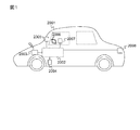
- FIG. 1 is a schematic view of a vehicle system 2001 on which a vehicle control device 2002 is mounted.
- the vehicle system 2001 includes a vehicle control device 2002, a wireless communication unit 2003, a drive device 2004, a recognition device 2005, an output device 2006, an input device 2007, and a notification device 2008.
- a vehicle control device 2002 is an electronic control device that controls a vehicle, that is, an ECU (Electronic Control Unit).
- the wireless communication unit 2003 acquires information such as a map.
- Drive device 2004 drives, for example, an engine, a wheel, a brake, a steering device, and the like to control the motion of the vehicle based on an operation command of vehicle control device 2002.
- the recognition device 2005 is, for example, a camera or a sensor that acquires information input from the outside world and outputs information for generating the outside world recognition information.
- the output device 2006 displays information such as vehicle speed and warning.
- the input device 2007 is, for example, a pedal, a steering wheel, or the like through which a driver inputs a vehicle operation instruction.
- the notification device 2008 is, for example, a lamp, an LED, a speaker, and the like that the vehicle system 2001 notifies the outside world of the state of the vehicle.
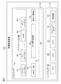
- FIG. 2 is an overall block diagram of the vehicle control device 2002. As shown in FIG. However, a detailed block diagram will be shown again later.
- the vehicle control device 2002 is composed of software 216 and hardware 215.
- the software 216 is realized by the CPU 208 described later loading a program stored in a ROM (not shown) into the memory 209 and executing the program.
- the hardware 215 includes a CPU 208 which is a central processing unit, a memory 209 which is a non-volatile storage device, a timer 210 which manages the timing of real time control, a network adapter 211 which accesses a network, a sensor, an automatic brake device, etc. And a peripheral device 212 of The CPU 208 is a so-called single core CPU provided with only one core. However, although the CPU 208 includes a plurality of cores, the case where only one core is used to execute the application unit 214 described later is included in the scope of the present embodiment.
- the software 216 includes an application unit 214, a shared data unit 205, a task execution control unit 206, an operation log management unit 213, and an OS 207 which is an operating system.
- the application unit 214 realizes a sensor fusion 201 that processes external information from peripheral devices such as a sensor device, a map fusion 202 that processes map information for automatic driving, a collision avoidance, a following operation, and a lane deviation prevention.
- the system includes an advanced driving assistant system (ADAS) 203, an auto parking 204 for realizing automatic parking, and the like.
- ADAS advanced driving assistant system
- the configuration of the application unit 214 described here is an example, and at least one application may be included.
- Each application is composed of a plurality of tasks, and the priority is set to each task.
- the shared data unit 205 manages data used by each application stored in the application unit 214.
- the shared data unit 205 secures, for example, a storage area in the memory 209, and manages reading and writing of data in the storage area.
- the task execution control unit 206 controls the execution of each task that constitutes an application. The detailed configuration and operation of the task execution control unit 206 will be described later.
- the action log management unit 213 records the action of each task.
- the task execution control unit 206 manages the tasks 101 and 102 described later by the task state management unit 107 based on the timing designated by the scheduling unit 108 based on the state transition described later.
- the OS 207 divides and executes the application into tasks, which are execution units, in order to execute the application included in the application unit 214.
- the OS 207 can execute a plurality of tasks almost simultaneously, but strictly speaking, the computing resources of the CPU 208 are used by time division. In other words, the OS 207 executes tasks one after another as time passes. Each task is performed within a "slot" which is a predetermined length of time.
- the tasks are not equally important in execution, and depending on the processing content, there are high priority tasks whose execution time must be guaranteed, and low priority tasks whose execution time may be slightly delayed.
- QM Quality Management
- ASIL Automotive Safety Integrity Level
- ASIL-B Automotive Safety Integrity Level
- ASIL-C Automotive Safety Integrity Level
- ASIL-D ASIL-D in order of functional safety from low to high hazard events.
- the tasks that must be guaranteed execution time in terms of security collateral are ASILs
- tasks that are not related to security and that may have a slightly delayed execution time are QM.
- a task with a classification of QM is a “low priority task” and a task with a classification of ASIL-D. Is also referred to as a "high priority task”.
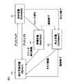
- FIG. 3 is a state transition diagram of tasks. Task states are classified into the following four states.
- the first state is a running state (RUNNING) 301.
- the execution state 301 is a state in which the CPU 208 is assigned and a task is being executed.
- the second state is the ready state (READY) 302.
- the third state is WAITING 303.
- the standby state 303 is a state in which execution is suspended until some condition is satisfied.
- the fourth state is DORMANT 304.
- the dormant state is a state in which the task has not been started yet or has ended.
- the newly created task starts in the dormant state 304 and transitions to the ready state 302 when the task is activated.
- the task is dispatched to transit to the execution state 301 to execute task processing.
- the task state transitions to the ready state 302 when the execution of the task is completed or the allocated slot time is over. If the task makes a resource request and acquisition of the resource can not be performed by exclusive control, the process transitions to the standby state 303. Thereafter, when the resource is released and the task can acquire the resource, the task state is transitioned from the standby state 303 to the executable state 302. When the task receives a forcible termination instruction or the task itself performs termination processing, the task state is transitioned to the pause state 304.
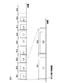
- FIG. 4 is a diagram showing an example of execution of a task controlled by time-driven scheduling.
- the time-driven scheduling is that the OS 207 executes a task for a determined time at a determined time according to a determined execution order.
- the horizontal axis represents the passage of time
- SL1 to SL9 in the drawings are IDs assigned to the respective slots (hereinafter referred to as "slot IDs").
- the task execution control unit 206 performs processing immediately after the start of each slot, and then the task is executed.
- the last slot ID is SL9 in FIG. 4, SL10, SL11,.
- Each task is performed within the time of the assigned slot.
- t_1 to t_3 shown in FIG. 4 are IDs for identifying tasks to be executed (hereinafter, “task IDs”).
- task IDs IDs for identifying tasks to be executed
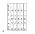
- FIG. 5 is a diagram showing an example of a scheduling table 501 used for time-driven scheduling.
- the scheduling table 501 is composed of a plurality of records, and each record has fields of slot ID, start time, end time, task ID, and time error determination flag.
- the slot ID field stores the slot ID of the record.
- the start time and end time fields store the start time and end time of the slot of the record. However, this time is the start time of SL1 is zero.
- the task ID field stores the task ID of the task to be executed in the record.
- a flag referred to by a scheduling unit 108 described later is stored in the field of the time error determination flag. The time error determination will be described in detail later.
- the scheduling table 501 is created in advance based on information such as the execution cycle of each task, the longest execution time assumed, and the safety requirement level.
- the length of one cycle of the scheduling table 501 is created so as to satisfy the execution cycles of all tasks. If the end of the cycle is reached, return to SL1 and continue scheduling. For example, in the example shown in FIG. 5, since the last slot ID is SL12 and the end time is "5.1 ms", the length of one cycle is 5.1 ms. Then, SL1 is executed next to SL12.
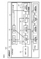
- FIG. 6 is a diagram showing a detailed configuration of the task execution control unit 206.
- the application unit 214 is described as including a plurality of first tasks 101 with a low safety requirement level and a plurality of second tasks 102 with a high safety requirement level.
- the first task 101 and the second task 102 are tasks constituting any of the applications included in the application unit 214.
- the first task 101 and the second task 102 are collectively referred to simply as a “task”.
- the task execution control unit 206 includes a data access control unit 105, a system state determination unit 106, a task state management unit 107, and a scheduling unit 108.
- the data access control unit 105 controls an access request from the task to the shared data unit 205 using an access flag described later.
- the system state determination unit 106 determines the state of the system with reference to a system state management unit 111 described later that manages the system state.
- the task state management unit 107 manages the state of tasks.
- the scheduling unit 108 performs task schedule management in cooperation with the data access control unit 105, the system state determination unit 106, and the task state management unit 107.
- the hardware 215 includes an access time monitoring unit 109, a slot time monitoring unit 110, and a system state management unit 111.
- the access time monitoring unit 109 is realized by the timer 210 and monitors the arrival of the set access monitoring time. The access monitoring time will be described later.
- the slot time monitoring unit 110 is realized by the timer 210 and monitors the arrival of each set slot time.
- the system state management unit 111 is realized by a hardware circuit (not shown) and manages the system state in cooperation with the access time monitoring unit 109 and the slot time monitoring unit 110.
- the access time monitoring unit 109, the slot time monitoring unit 110, and the system state management unit 111 are described as being configured by hardware, but the inclusion of software is not excluded. However, when software is included, the resource is independent of software 216, and the operation timing of access time monitoring unit 109, slot time monitoring unit 110, and system state management unit 111 affects the operation timing of software 216. I will not give it.
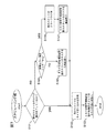
- FIG. 7 is a flowchart showing the operation of the scheduling unit 108.
- the scheduling unit 108 starts operation according to an operation command from the timer 210.
- the execution subject of each step described below is the CPU 208.
- the scheduling unit 108 first determines whether the task in the previous slot has been completed (S101). If it is determined that the task of the previous slot has been completed (S101: yes), the scheduling unit 108 causes the timer 210 to start operation of the scheduling unit 108 at the end time of the current slot in the scheduling table 501. It sets (S102). Then, the scheduling unit 108 shifts the task assigned to the current slot to the execution state (S103). If no task is assigned to a slot, the task is not run on that slot. By performing task execution processing at a time determined in this manner, the execution time of each task is secured. The processing of the task transitioned to the execution state will be described later with reference to FIG.
- the scheduling unit 108 refers to the time error determination flag of that slot in the scheduling table 501, and does not execute it (S104: No) To shift the task of the previous slot to the standby state 303 (S105).
- a task to be transitioned to the standby state 303 in other words, a task whose time error determination is “perform” in the scheduling table 501 is referred to as a “cross task”.
- the cross task is a task requiring a long time in which processing is not completed in one slot, and operates across a plurality of slots.
- the time error determination flag is "ON" (S104: yes)
- the error flag of the previous slot is set (S106), and the task of the previous slot is transitioned to the pause state 304 (S107). Since it takes time to force termination, the task may be temporarily transitioned to the standby state 303 in S107, and may be transitioned to the idle state 304 in an empty slot. If execution of S105 or S107 is completed, it will progress to above-mentioned S102.
- FIG. 8 is a flowchart showing the operation of each task in the execution state.
- the task executes task processing including access to the shared data unit 205 (S301), and indicates the scheduling unit 108 that execution has been completed by setting an execution completion flag (S302) when the execution is completed.
- the scheduling unit 108 refers to the execution completion flag of the task executed in the immediately preceding slot, and transitions the task to the executable state 302 if the execution completion flag is raised.
- the execution completion flag is lowered (S303). However, the scheduling unit 108 may lower the execution completion flag.
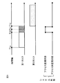
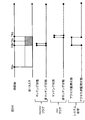
- FIG. 9 is a diagram for explaining the data access monitoring time of the task.
- FIG. 9 shows a state in which the first task 101 and the second task 102 are executed. Then, the first task 101 operates between allocated slot times T1a to T1d. In the slot assigned to the first task 101, an access monitoring time for monitoring data access is provided at T1b to T1d at the end of the slot.
- the length of the access monitoring time is a data access time, that is, a time required for the task to access the shared data unit 205, for example, a time longer than T1b to T1c.
- the length of the access monitoring time is constant regardless of the task. Since the second task 102 has a high safety requirement level, no access monitoring time is set for the slot assigned to the second task 102.
- the time which is the access monitoring time is called the "access monitoring state", and the time which is not the access monitoring time is called the "access non-monitoring state".
- the state in which the access monitoring state or the access non-monitoring state is taken is called "system state”.
- the system state is in the access non-monitoring state during normal time, and access monitoring is performed from the predetermined time before the end of the slot to which the first task 101 belongs to the end time of the slot to which the first task 101 belongs. It becomes a state.
- FIG. 10 is a flowchart showing the operation of the system state management unit 111.
- the operation of the system state management unit 111 will be described below with reference to FIG.
- the execution subject of each step described below is the CPU 208.
- the system state management unit 111 determines whether or not the task to be executed in that slot is the first task 101 at time T1a in FIG. 9 (S400A). If it is determined that the task is one task 101, the process proceeds to step S401. If it is determined that the task to be executed is not the first task 101, that is, the second task 102 is to be executed, the slot end time is set in the slot time monitoring unit 110 (S400B), and counting by the timer 210 is started. Let it go and go to S404. In S401, the system state management unit 111 sets the start time of the access monitoring time in the slot time monitoring unit 110 and sets the end time of the slot in the slot time monitoring unit 110 to start counting.
- the system state management unit 111 monitors the register state of the access time monitoring unit 109, and determines from the register state whether or not the access monitoring time set has been reached (S402), and determines that the access monitoring time has not been reached. If so, it remains at S402. When judging that the access monitoring time has arrived, the system state management unit 111 changes the system state from the access non-monitoring state to the access monitoring state (S403).
- the system state management unit 111 monitors the register state of the slot time monitoring unit 110 and determines from the register state whether or not the slot end time set has been reached (S404), and the slot end time has not been reached. If it is determined that the above is true, the process remains at S404. When judging that the slot end time has been reached, the system state management unit 111 changes the system state from the access monitoring state to the access non-monitoring state (S405). In the subsequent S406, the system state management unit 111 determines whether the system is ended, for example, whether the ignition key switch of the vehicle equipped with the vehicle control device 2002 is turned off. If the system state management unit 111 determines that the system is not to be ended, the process returns to S400A, and if it is determined that the system is to be ended, the operation illustrated in FIG. 10 is ended.
- FIG. 11 is a flowchart showing the operation of the task state management unit 107.
- the task state management unit 107 also designates which state to transition to when being called. That is, the task state management unit 107 is called along with designation of any one of the standby state, the pause state, and the executable state.
- the task state management unit 107 When the transition to the standby state is designated (S501: YES), the task state management unit 107 causes the task to transition to the standby state (S502). If it is determined that the designated state is not the standby state (S501: NO), it is determined whether the transition to the hibernation state is designated (S503). The task state management unit 107 transitions the task to the hibernate state if it is determined that transition to the hibernate state is specified (S504), and determines that the transition to the hibernate state is not specified. A transition to an executable state is made (S505).
- FIG. 12 is a schematic view showing the access to the shared data unit 205 by the first task 101.
- the data access control unit 105 acquires the system state managed by the system state management unit 111 via the system state determination unit 106.
- the data access control unit 105 permits access to the shared data unit 205 by the first task 101 when determining that the system state is the access non-monitoring state.
- the data access control unit 105 rejects the access to the shared data unit 205 by the first task 101, and further uses the task state management unit 107 to execute the first task 101.
- the transition to the pause state 304 is made. However, when the system state is the access monitoring state, the data access control unit 105 does not transition the task state of the first task 101 to the pause state 304, but causes the transition to the standby state 303 or an infinite loop to execute time error It may be determined.
- FIG. 13 is a diagram for explaining the access monitoring time of the straddle task.
- the example shown in FIG. 13 shows a state in which the first task 101 and the second task 102 are executed.
- the first task 101 operates across a plurality of slots, and more specifically, operates with slots from time T2a to T2d and slots from time T2e to T2h. That is, the first task 101 in this example is a straddle task.
- the access monitoring time for data access monitoring is provided at the end of the slot in all the slots assigned to the task with the lower safety requirement level.
- times T2b to T2d and times T2f to T2h are access monitoring times.
- the system state is set to the access monitoring state in accordance with the access monitoring time.
- the data access control unit 105 When the first task 101 attempts to access the shared data unit 205, the data access control unit 105 performs the following processing when the system state is the access monitoring state. That is, the data access control unit 105 prohibits the access to the shared data unit 205 by the first task 101, and causes the task state management unit 107 to shift the task state of the first task 101 to the standby state. However, when the system state is the access monitoring state, the task state of the first task 101 may not be transitioned to the standby state 303, but an infinite loop may be executed to transition to the standby state 303 by time error determination.
- the access to the shared data unit 205 by the first task 101 is started at times other than the access monitoring time of the slot following the first task 101, that is, at time T2e to T2f.
- the first task 101 attempts to access the shared data unit 205, if the system state is the access non-monitoring state, access to the shared data unit 205 by the first task 101 is performed.
- FIG. 14 is a diagram showing an example of setting of the access monitoring time.
- the access monitoring time does not depend on the activation timing of a task with a high safety requirement level but is determined by the slot time of a task with a low safety requirement level.
- the third task has a low safety requirement level like the first task 101.
- the first task 101 operates at times T3a to T3d and at times T3j to T3l.
- the third task operates from time T3f to time T3h.
- the access monitoring time is allocated at time T3b to T3d, time T3f to T3h, and time T3j to T3l, which are the ends of the slots allocated to the first task 101 and the third task, respectively.
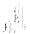
- FIG. 15 is a flowchart showing the operation of the data access control unit 105.
- the execution subject of each step described below is the CPU 208.
- the system state determination unit 106 confirms the system state (S201).
- the data access control unit 105 determines that the system state is the access non-monitoring state (S201: No)
- the access flag indicating the access status to the shared data unit 205 is transitioned to "accessing" (S202)
- the access to the data unit 205 is executed (S203).
- the data access control unit 105 causes the access flag to transition to "not in access" (S204).
- the data access control unit 105 determines the content of the time error determination flag of the current slot in the scheduling table 501 (S205). If the time error determination flag is "do not" (S205: No), the data access control unit 105 causes the task state management unit 107 to shift the state of the task to the standby state 303 (S206). Then, the data access control unit 105 performs data access after the task state transitions to the execution state 301 in the subsequent slots (S202, S203, S204).
- the data access control unit 105 causes the error flag in the margin of the current slot to transition to ON (S207), and forcibly terminates the task in the execution state 301.
- the sleep state 304 is set (S208). However, since it takes time for forced termination, the task may be temporarily transitioned to the standby state 303 in S208, and may be transitioned to the idle state 304 in an empty slot.
- the vehicle control device 2002 executes an application unit 214 including a first task 101 relatively low in priority classified according to the priority of execution and a second task 102 relatively high in priority, and a task to be executed
- a system state management unit which assigns a slot having a predetermined length of time for each task and sets a first predetermined time at the end of the slot as an access monitoring time in the slot assigned to the first task 101 And 111, a shared data unit 205 accessed by the first task 101 and the second task 102, and a data access control unit 105 inhibiting access to the shared data unit 205 by the first task 101 during access monitoring time.
- the vehicle control device 2002 does not have information such as which task accesses the shared data unit 205, and further, which data included in the shared data unit 205 is accessed. However, since the access monitoring time is provided at the end of the slot to which the first task 101 is assigned, the shared data section 205 by another task is caused by the first task 101 having a low priority accessing the shared data section 205. It is possible to prevent a situation where access to the site is blocked.
- the conventional problems assumed are described with reference to FIG.
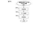
- FIG. 16 is a flowchart showing a general access procedure to shared data.
- the task for accessing shared data acquires exclusion, in other words, acquires the access right to shared data (S601).
- data processing is performed (S602), and finally exclusion is released, in other words, access to shared data is released (S603), and a series of processing is ended.
- the slot of the task performing the process shown in FIG. 16 ends in the middle of data processing, the process shifts to another task without exclusive release. In that case, exclusive release is not performed unless the processing of the task is resumed, and other tasks can not obtain exclusive access until that time, and access to shared data becomes impossible.
- the vehicle control device 2002 uses the predetermined time at the end of the slot assigned to the first task 101 as the access monitoring time, and accesses the shared data unit 205 in the access monitoring time. Because it is prohibited, the above-mentioned problems can be avoided. That is, in the vehicle control device 2002, since the first task 101 does not reach the end of the slot while holding the access right, the exclusive acquisition of the first task 101 adversely affects the access to the shared data portion 205 to other tasks. Can be prevented. Furthermore, this advantage is also obtained when the vehicle control device 2002 does not have the access to the shared data unit 205 for each task as in the present embodiment. That is, the vehicle control device 2002 can prevent the influence on the operation of other tasks due to the exclusion acquisition of the first task 101 having a low safety requirement level regardless of the presence or absence of the access information of the shared data unit 205 used for exclusion control.
- the access monitoring time is longer than the time required for the first task 101 to access shared data. Therefore, access to the shared data unit 205 by the first task 101 is permitted before the start of the access monitoring time in which the first task 101 has sufficient time to access the shared data unit 205. Also when the first task 101 starts access to the shared data unit 205 immediately before the access monitoring time, the access monitoring time is longer than the time required for the first task 101 to access shared data, so the slot It is possible to complete up to exclusive release within and prevent the influence on the operation of other tasks.
- the data access control unit 105 causes the first task 101, which has attempted to access the shared data unit 205 at access monitoring time, to transition to the end state. Therefore, the operation of the first task 101 incapable of accessing the shared data unit 205, which is the next process, can be ended, and the resources of the CPU 208 can be saved.
- the priority is determined based on the level of functional safety required for the task. Specifically, the required functional safety level is high, for example, the task of ASIL-D is set to have a high priority, and the required functional safety level is low, for example, the task for QM is set to be low. As a result, tasks with a high functional safety level are preferentially executed.
- Modification 1 In the first embodiment, only two priorities are set. However, three or more priorities may be set. In that case, the processing is classified into the highest priority and the other priorities. For example, when priority is given to 1 to 5 and priority is to be given to a larger number, tasks with priorities 1 to 4 correspond to tasks with low priority in the first embodiment, that is, the first task 101. Do. Then, only the task of priority 5 corresponds to the high priority task in the first embodiment, that is, the second task 102.
- the priority is determined based on the functional safety level required for the task.
- other indicators may determine the priority of the task.
- the priority of a task may be determined based on the magnitude of influence on other tasks, the preference of the user, or the functional safety level and the combination thereof.
- FIG. 1 A second embodiment of a vehicle control device which is an access control device will be described with reference to FIG.
- the same components as in the first embodiment will be assigned the same reference numerals and differences will be mainly described.
- the points that are not particularly described are the same as in the first embodiment.
- the present embodiment is different from the first embodiment mainly in that the case where access to the shared data unit 205 is not completed in the slot is taken into consideration. That is, in the second embodiment, the following tasks are assumed. That is, a certain task starts access to the shared data unit 205 before the access monitoring time starts, and the access does not end even if the access monitoring time starts. Furthermore, the task did not end access to the shared data unit 205 even if the access monitoring time ends, in other words, even when the end time of the slot is reached.
- the access flag of the data access control unit 105 is utilized.
- the access flag is, for example, information stored in the memory 209.
- the data access control unit 105 when the data access control unit 105 permits access to the shared data unit 205 in response to a request for a task, the data access control unit 105 makes the access flag transition to “accessing”, and The access flag is transitioned to "not in access” when the access is completed.
- the data control control unit 105 detects that the access flag is “accessing” at the end of the access monitoring time, the data control control unit 105 restarts the vehicle control device 2002 to reset all exclusive control.
- the task state is the execution state and the access flag is “accessing” at the start of the access monitoring time, it may be determined that an abnormality has occurred and the task state management unit 107 may shift the task to the standby state.
- the restart target is not limited to the vehicle control device 2002, and may be restarted in the entire other mounted system.
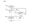
- FIG. 17 is a flowchart showing the operation of the data access control unit 105 in the second embodiment.
- the processing up to step S203 is the same as that of the first embodiment, and thus the description thereof is omitted.
- the data access control unit 105 determines whether the access to the shared data unit 205 by the task is ended, and if it is determined that the access is ended (S211) : YES), go to S204.
- the data access control unit 105 determines whether the access monitoring time has ended, and if it is determined that the access monitoring time has ended (S212: Yes) ) Restarts the vehicle control device 2002 (S213). If the data access control unit 105 determines that the access monitoring time has not ended (S212: No), the process returns to S211.
- the vehicle control device 2002 turns on the access flag indicating the access state to the shared data unit 205 by the task and the access flag when the task starts the access to the shared data unit 205, and the task to the shared data unit 205
- the data access control unit 105 which turns off the access flag when the access of The data access control unit 105 restarts the vehicle control device 2002 if the access flag is on at the end of the access monitoring time. Therefore, it is possible to minimize the influence of exclusion on other tasks when data access is performed beyond the access monitoring time, and early recovery is possible.
- FIG. 1 A third embodiment of a vehicle control device which is an access control device will be described with reference to FIG.
- the same components as in the first embodiment will be assigned the same reference numerals and differences will be mainly described.
- the points that are not particularly described are the same as in the first embodiment.
- the present embodiment is different from the first embodiment mainly in that an access monitoring time may be provided to a slot assigned to the second task 102.
- an operation of the vehicle control device 2002 when the second task 102 having a high safety requirement level is not permitted to affect other tasks will be described. That is, in the present embodiment, even when the second slot next to the slot assigned to the second task 102 is assigned to the second task 102, data access is made to the last part of the slot assigned to the previous second task 102. Provide access monitoring time for monitoring. As a result, when the second task 102 having a high safety requirement level malfunctions, it is possible to prevent the influence on the other second safety tasks 102 having a high safety requirement level.
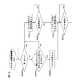
- FIG. 18 is a flowchart showing the operation of the system state management unit 111 in the third embodiment. The same steps as those in the first embodiment are given the same step numbers, and the description thereof is omitted. If a negative determination is made in S400A, the system state management unit 111 determines whether the second task 102 is assigned to both the current slot and the next slot (S400C). If the present step is affirmed, the system state management unit 111 proceeds to S401, and if the negative determination is made, the process proceeds to S400B. The following operation is the same as that of the first embodiment, and hence the description is omitted.
- a fourth embodiment of a vehicle control device which is an access control device will be described.
- the same components as in the first embodiment will be assigned the same reference numerals and differences will be mainly described.
- the points that are not particularly described are the same as in the first embodiment.
- the present embodiment differs from the first embodiment mainly in that the scheduling table 501 is automatically generated.
- a development tool (not shown) automatically generates a scheduling table 501.
- the development tool automatically generates a scheduling table 501 from design information such as the cycle of each task, the worst execution time, and the safety requirement level.
- design information such as the cycle of each task, the worst execution time, and the safety requirement level.
- it is determined whether to provide an access monitoring time for data access monitoring at the final part of each slot based on the information of the safety requirement level.
- the slot time including the access monitoring time is arranged.
- the scheduling table 501 is automatically generated, application design can be performed without considering the necessity of access monitoring time.
- FIGS. 19-23 A fifth embodiment of a vehicle control device, which is an access control device, will be described with reference to FIGS. 19-23.
- the same components as in the first embodiment will be assigned the same reference numerals and differences will be mainly described.
- the points that are not particularly described are the same as in the first embodiment.
- the present embodiment is different from the first embodiment mainly in that the CPU 208 of the vehicle control device 2002 includes a plurality of cores.
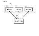
- the CPU 208 in the present embodiment is a so-called multi-core CPU provided with a first core 1701, a second core 1702, and a third core 1703 as shown in FIG. 19.
- the number of cores provided in the CPU 208 may be two or more, and the number is not limited.
- Each core executes the first task 101 with a low safety requirement level and the second task 102 with a high safety requirement level, and each task accesses the shared data unit 205.
- the system status is classified into three, that is, the overall monitoring status, the individual monitoring status, and the non-monitoring status.
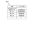
- FIG. 20 is a diagram showing an example of the system status table 1901.
- the system state table 1901 holds information as to whether each core is in an individual monitoring state or a non-monitoring state, and an "all core access monitoring counter".
- the access monitor counter for all cores increases and decreases between 0 and the number of cores.
- a state in which the value of the access monitor counter for all cores is 1 or more is referred to as a "general monitoring state. That is, the access monitoring state and the access non-monitoring state in the first embodiment correspond to the individual monitoring state and the non-monitoring state in the present embodiment, and indicate the accessibility to the shared data unit 205 in each core.
- the general monitoring state affects the whole of the vehicle control device 2002, that is, all the cores. In the general monitoring state, new access to the shared data unit 205 by the first task 101 in all the cores is prohibited.
- the system state management unit 111 sets monitoring time not only for the first task 101 but also for the second task 102.
- the monitoring time of the second task 102 is set to be twice or more the access time.
- the system state management unit 111 shifts the system state of the first core to the individual monitoring state.
- the system state management unit 111 shifts the system state of the first core to the non-monitoring state. As described above, in the core in the individual monitoring state, new access to the shared data unit 205 in the first task 101 is prohibited.
- the system state management unit 111 causes the system state of that core to transition to the individual monitoring state, and increments the access monitoring counter for all cores by one. Transition to the overall monitoring state.
- the system state management unit 111 causes the system state of the core to transition to the non-monitoring state and decrements the access monitoring counter for all cores by one. When the value of the access monitor counter for all cores becomes zero due to this decrement, the general monitoring state is released.
- the access monitor counter for all cores is 1 or more, the entire monitor state is established, and new data access to the shared data unit 205 by the first task 101 in all cores is prohibited.
- the data access control unit 105 selects the second task with the shortest time until the end time of the slot being executed. Prioritize data access by 102.
- the data access control unit 105 performs the second task 102 in the order in which the requests are received.
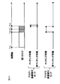
- FIG. 22 is a diagram showing a situation in which the access request to the shared data unit 205 by the second task 102 is duplicated.
- FIG. 22 is a schematic view, and the length of the time axis is not uniform.
- the access time of the third core 1703 is drawn to be very long in FIG. 22 as compared to the others, this is due to the problem of drawing, and all the access times are substantially the same.
- the first core 1701 and the second core 1702 execute the second task 102
- the third core 1703 executes the first task 101.
- the end time of the slot in the first core 1701 is t6, which is calculated from the monitoring time of the second task 102 and becomes the entire monitoring time from time t3.
- the end time of the slot in the second core 1702 is t7, which is calculated from the monitoring time of the second task 102 and becomes the entire monitoring time from time t5.
- the first task 101 in the third core 1703 accesses the shared data unit 205. This access continues until time t4.
- the second core 1702 As indicated by the downward triangle at time t1, the second core 1702 generates an access request to the shared data unit 205 by the second task 102.
- the first core 1703 At time t2, as indicated by a downward triangle, the first core 1703 generates an access request to the shared data unit 205 by the second task 102.
- the entire monitoring time starts in the first core 1703.
- the data access control unit 105 causes the first core 1701 to have a shorter time to the end of the slot than the second core 1702 It is determined that the second task 102 of the first core 1701 accesses the shared data unit 205. Thereafter, when access to the shared data unit 205 by the first core 1701 is completed at time t5, the data access control unit 105 starts access to the shared data unit 205 by the second core 1702.
- FIG. 23 is a flowchart showing the operation of the system state management unit 111 in the fifth embodiment.
- the system state management unit 111 determines whether the task executed in the slot at the start of each slot is the first task 101 (S400A), and determines that the task executed is the first task 101. In the case (S400A: Yes), the process proceeds to S401A. When it is determined that the task to be executed is not the first task 101, that is, the second task 102 is to be executed (S400A: No), the following process is performed in S400B.
- system state management unit 111 sets the slot end time in slot time monitoring unit 110 and calculates the start time of access monitoring time based on the monitoring time for second task 102 and sets it in access time monitoring unit 109.
- the counting is started (S400B).
- the system state management unit 111 determines that it is the monitoring time (S402B: Yes)
- the state is changed (S403B), and the process proceeds to S404.
- the system status is already in the overall monitoring status, only incrementing of the access monitoring counter for all cores is performed.
- the system state management unit 111 calculates the start time of the access monitoring time based on the monitoring time for the first task 101, sets the time in the access time monitoring unit 109, and monitors the slot end time as the slot time.
- the unit 110 is set to start counting and the process advances to step S402. If the system state management unit 111 determines in S402 that the monitoring time is reached (S402A: Yes), the system monitoring state of the core is transitioned to the individual monitoring state, and the process proceeds to S404 (S403A). If it is determined in S404 that it is the slot time, the system monitoring state of the core is transitioned to the non-monitoring state, and the access monitoring counter for all cores is decremented (S405A). If the value of the access monitor counter for all cores becomes zero by this decrement, the entire monitoring state is released.
- a plurality of cores of the CPU 208 for executing tasks are provided, and in the slot allocated to the second task 102, the system state management unit 111 sets the second predetermined time at the end of the slot as the overall monitoring time The length of time is longer than the individual monitoring time.
- the data access control unit 105 determines whether or not it is the access monitoring time for each core of the CPU 208, and prohibits the access to the shared data unit 205 by the first task 101 executed by all the cores in the entire monitoring time. .
- an access monitoring time is provided for each core to affect the tasks with high safety requirement levels by the tasks with low safety requirement levels. Can be prevented. Also, by providing an overall monitoring time at the end of the slot of the second task 102 and restricting the access to the shared data part 205 of the first task 101 in all cores, the second task 102 executed in any core is also shared. The access to the data unit 205 can be prioritized to prevent a delay in execution.
- the data access control unit 105 performs the second task in which the time until the end of the slot being executed is less than the total monitoring time. Priority is given to access to the shared data unit 205 by 102. Therefore, when access to the shared data unit 205 of the second tasks 102 is duplicated, priority is given to access by a task having a short time until the end of execution, and as long as access to the shared data unit 205 by the second task 102 is possible. provide.
- the overall monitoring time may be longer than the product of the time required for the task to access the shared data unit 205 and the number of cores. This can prevent the influence of data access of the second task 102 being executed by another core.
- FIG. 1 A sixth embodiment of a vehicle control device which is an access control device will be described with reference to FIG.
- the same components as in the first embodiment will be assigned the same reference numerals and differences will be mainly described.
- the points that are not particularly described are the same as in the first embodiment.
- the present embodiment differs from the first embodiment mainly in that the system state management unit is not provided.
- system state management is performed by using a plurality of hardware timer modes and a plurality of flags corresponding to the modes in place of the system state management unit 111.
- the timer holds a flag indicating that the set time has come.
- FIG. 24 is a diagram showing an outline of the operation in the present embodiment. The operation of the timer will be described with reference to FIG.
- the continuous execution mode which is the first mode
- the flag 1 is shifted to the matching state
- the counter is reset to 0, and counting is started again.
- flag 1 transitions to the non-matching state.
- the system state determination unit 106 refers to the flag 2.
- the flag 2 determines that the access monitoring state is set, and the data access control unit 105 prohibits data access of the task.
- management of the system state can be realized only by the hardware timer by using a plurality of timer modes in combination.
- FIG. 25 to 26 A seventh embodiment of a vehicle control device, which is an access control device, will be described with reference to FIGS. 25 to 26.
- FIG. 25 to 26 the same components as in the first embodiment will be assigned the same reference numerals and differences will be mainly described. The points that are not particularly described are the same as in the first embodiment.
- the present embodiment differs from the first embodiment mainly in that an FPGA is used.
- FIG. 25 is a block diagram of a vehicle control device 2002 in the seventh embodiment.
- the access time monitoring unit 109, the slot time monitoring unit 110, and the system state management unit 111 are configured on an FPGA (field-programmable gate array).
- a timer flag monitoring unit 2303 is further provided on the FPGA.
- FIG. 26 is a diagram for explaining the operation of the timer flag monitoring unit 2303.
- the timer flag monitoring unit 2303 constantly compares the times of the access time monitoring unit 109 and the slot time monitoring unit 110 with the timer. When the timer matches the access time monitoring unit 109 (time T6b in FIG. 26), the timer flag monitoring unit 2303 changes the monitor flag to the matching state, and when the slot time monitoring unit matches the timer (time T6d), the slot flag Transition to the matching state.
- the system state management unit 111 monitors the state transition of the monitor flag and the slot flag, and transitions the system state to the access monitoring state when the monitor flag changes to the matching state (time T6b). When the slot flag is transitioned to the matching state (time T6d), the system state management unit 111 transitions the system state to the access non-monitoring state.
- one timer can monitor a plurality of times by time monitoring and state management using an FPGA.
- FIGS. An eighth embodiment of a vehicle control device, which is an access control device, will be described with reference to FIGS.
- the same components as in the first embodiment will be assigned the same reference numerals and differences will be mainly described.
- the points that are not particularly described are the same as in the first embodiment.
- the present embodiment is different from the first embodiment mainly in that the operation of the operation log management unit 213 is clarified.
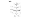
- FIG. 27 is a flowchart showing the operation of the operation log management unit 213.
- the operation log management unit 213 acquires (S701, S702) and records the start time and end time of the task in each slot, the task ID, and the state at the end of the slot (S703). In particular, by recording the state at the end, whether the task is operating normally, whether it is a straddling task with a long operation time, forced termination due to the occurrence of an abnormality, or data access within the access monitoring time It holds in the operation log whether it is end or interruption across data access within access monitoring time.
- FIG. 28 is a diagram showing an example of the operation log 1101 recorded by the operation log management unit 213.
- the operation log 1101 records the start time, end time, task ID, and end state of each slot.
Landscapes
- Engineering & Computer Science (AREA)
- Software Systems (AREA)
- Theoretical Computer Science (AREA)
- Physics & Mathematics (AREA)
- General Engineering & Computer Science (AREA)
- General Physics & Mathematics (AREA)
- Debugging And Monitoring (AREA)
Abstract
優先度の低いタスクの共有データへの排他取得による他タスクの動作への影響を防ぐことができる。アクセス制御装置は、実行の優先度により分類され相対的に優先度が低い第1タスクおよび相対的に優先度が高い第2タスクを含むアプリケーション部と、第1タスクおよび第2タスクを実行する実行部と、実行されるタスクごとに、タスクごとのあらかじめ定められた長さの時間であるスロットを割り当て、第1タスクに割り当てたスロットにおいて、スロットの末尾の第1の所定時間をアクセス監視時間に設定するシステム状態管理部と、第1タスクおよび第2タスクによりアクセスされる共有データ部と、アクセス監視時間における第1タスクによる共有データ部へのアクセスを禁止するデータアクセス制御部とを備える。
Description
本発明は、アクセス制御装置に関する。
制御装置では優先度が異なる様々なタスクが実行される。優先度が低いタスクにより優先度が高いタスクの動作を妨げないことが求められる。特許文献1には、実行開始予定時刻が予測可能な第1のタスクと共有資源を占有使用する時間長が既知である第2のタスクとが資源を共有するシステムにおいて、前記第1のタスクの優先度が前記第2のタスクの優先度よりも高いという条件の元でタスクのスケジューリングを行うタスク実行制御装置であって、前記第2のタスクによる共有資源の占有に先立って、前記第1のタスクの次回実行開始予定時刻と前記第2のタスクが前記共有資源を解放すると予想される解放予定時刻とを求める時間算出手段と、前記次回実行開始予定時刻と前記解放予定時刻とを比較して、前記解放予定時刻より前記次回実行開始予定時刻が早ければ、前記第2のタスクに前記共有資源の占有を許さず、一方、前記解放予定時刻より前記次回実行開始予定時刻が早くなければ、前記第2のタスクに前記共有資源の占有を許す資源管理手段、を有するタスク実行制御装置が開示されている。
特許文献1に記載されている発明では、優先度の低いタスクの共有データへの排他取得による他タスクの動作への影響を防ぐことができない。
本発明の第1の態様によるアクセス制御装置は、実行の優先度により分類され相対的に優先度が低い第1タスクおよび相対的に優先度が高い第2タスクを含むアプリケーション部と、前記第1タスクおよび前記第2タスクを実行する実行部と、実行されるタスクごとに、タスクごとのあらかじめ定められた長さの時間であるスロットを割り当て、前記第1タスクに割り当てた前記スロットにおいて、前記スロットの末尾の第1の所定時間をアクセス監視時間に設定するシステム状態管理部と、前記第1タスクおよび前記第2タスクによりアクセスされる共有データ部と、前記アクセス監視時間における前記第1タスクによる前記共有データ部へのアクセスを禁止するデータアクセス制御部とを備える。
本発明によれば、優先度の低いタスクの共有データへの排他取得による他タスクの動作への影響を防ぐことができる。
―第1の実施の形態―
以下、図1~図16を参照して、アクセス制御装置である車両制御装置の第1の実施の形態を説明する。
以下、図1~図16を参照して、アクセス制御装置である車両制御装置の第1の実施の形態を説明する。
<車両システムの構成>
図1は車両制御装置2002を搭載する車両システム2001の概要図である。車両システム2001は、車両制御装置2002と、無線通信部2003と、駆動装置2004と、認識装置2005と、出力装置2006と、入力装置2007と、通知装置2008とを備える。車両制御装置2002は車両を制御する電子制御装置、すなわちECU(Electronic Control Unit)である。無線通信部2003は地図などの情報を取得する。駆動装置2004は、車両制御装置2002の動作指令に基づき、車両の運動を制御するために、たとえばエンジン、ホイール、ブレーキ、操舵装置などを駆動する。認識装置2005は、外界から入力される情報を取得し、外界認識情報を生成するための情報を出力する、たとえばカメラやセンサーなどである。出力装置2006は、車両の速度や警告などの情報を表示する。入力装置2007は、運転者が車両操作の指示を入力する、たとえばペダル、ハンドルなどである。通知装置2008は、車両システム2001が外界に対して車両の状態等を通知する、たとえばランプ、LED、スピーカなどである。
図1は車両制御装置2002を搭載する車両システム2001の概要図である。車両システム2001は、車両制御装置2002と、無線通信部2003と、駆動装置2004と、認識装置2005と、出力装置2006と、入力装置2007と、通知装置2008とを備える。車両制御装置2002は車両を制御する電子制御装置、すなわちECU(Electronic Control Unit)である。無線通信部2003は地図などの情報を取得する。駆動装置2004は、車両制御装置2002の動作指令に基づき、車両の運動を制御するために、たとえばエンジン、ホイール、ブレーキ、操舵装置などを駆動する。認識装置2005は、外界から入力される情報を取得し、外界認識情報を生成するための情報を出力する、たとえばカメラやセンサーなどである。出力装置2006は、車両の速度や警告などの情報を表示する。入力装置2007は、運転者が車両操作の指示を入力する、たとえばペダル、ハンドルなどである。通知装置2008は、車両システム2001が外界に対して車両の状態等を通知する、たとえばランプ、LED、スピーカなどである。
<自動運転ECUの構成>
図2は車両制御装置2002の全体ブロック図である。ただし詳細なブロック図は後に改めて示す。車両制御装置2002は、ソフトウエア216とハードウエア215とから構成される。ソフトウエア216は、後述するCPU208が不図示のROMに格納されるプログラムをメモリ209に展開して実行されることにより実現される。
図2は車両制御装置2002の全体ブロック図である。ただし詳細なブロック図は後に改めて示す。車両制御装置2002は、ソフトウエア216とハードウエア215とから構成される。ソフトウエア216は、後述するCPU208が不図示のROMに格納されるプログラムをメモリ209に展開して実行されることにより実現される。
ハードウエア215は、中央演算装置であるCPU208と、不揮発性の記憶装置であるメモリ209と、リアルタイム制御のタイミングを管理するタイマ210と、ネットワークにアクセスするネットワークアダプタ211と、センサーや自動ブレーキ装置などの周辺装置212とを備える。CPU208はコアを1つのみ備える、いわゆるシングルコアCPUである。ただしCPU208が複数のコアを備えるが、後述するアプリケーション部214の実行には1つのコアしか使用しない場合も本実施の形態の範囲に含まれる。ソフトウエア216は、アプリケーション部214と、共有データ部205と、タスク実行制御部206と、動作ログ管理部213と、オペレーティングシステムであるOS207とを備える。
アプリケーション部214は、センサーデバイス等の周辺装置から外部情報を処理するセンサーフュージョン201と、自動運転のための地図情報を処理するマップフュージョン202と、追突回避、追従運転、および車線逸脱防止を実現するADAS(Advanced Driving Assistant System)203と、自動駐車を実現するオートパーキング204などを含んで構成される。ただしここで説明したアプリケーション部214の構成は一例であり、少なくとも1つのアプリケーションが含まれていればよい。なおそれぞれのアプリケーションは、複数のタスクから構成され、各タスクには優先度が設定される。
共有データ部205は、アプリケーション部214に格納されるそれぞれのアプリケーションで使用されるデータを管理する。共有データ部205はたとえばメモリ209に格納領域を確保し、その格納領域におけるデータの読み書きを管理する。タスク実行制御部206は、アプリケーションを構成するそれぞれのタスクの実行を制御する。タスク実行制御部206の詳しい構成および動作は後述する。動作ログ管理部213は、それぞれのタスクの動作を記録する。タスク実行制御部206はスケジューリング部108の指定したタイミングに基づきタスク状態管理部107により後述する各タスク101、102に対して、後述する状態遷移に基づき管理を行う。
<タスク>
OS207は、アプリケーション部214に含まれるアプリケーションを実行するために、アプリケーションを実行単位であるタスクに分けて実行する。OS207は複数のタスクを略同時に実行可能であるが、厳密にはCPU208の計算資源を時分割で利用する。換言するとOS207は、時間の経過にしたがって次々とタスクを実行する。それぞれのタスクは、あらかじめ定められた長さの時間である「スロット」内で実行される。
OS207は、アプリケーション部214に含まれるアプリケーションを実行するために、アプリケーションを実行単位であるタスクに分けて実行する。OS207は複数のタスクを略同時に実行可能であるが、厳密にはCPU208の計算資源を時分割で利用する。換言するとOS207は、時間の経過にしたがって次々とタスクを実行する。それぞれのタスクは、あらかじめ定められた長さの時間である「スロット」内で実行される。
タスクは実行の重要性が平等ではなく、その処理内容に応じて、実行時間を保証しなければならない優先度が高いタスクと、実行時間が多少遅れてもよい優先度が低いタスクがある。ISO26262では機能安全の視点からタスクを危険事象の低いものから高いものの順にQM(Quality Management)、ASIL(Automotive Safety Integrity Level)-A、ASIL-B,ASIL-C,ASIL-Dに分類している。すなわち大きく分類すると、安全性担保という点において実行時間を保証しなければならないタスクはASIL、安全保障に関係がなく実行時間が多少遅れてもよいタスクはQMとなる。また本実施の形態では、実行時間の保証の必要性を優先度の高さで言い換える場合があり、たとえば分類がQMであるタスクは「優先度が低いタスク」、分類がASIL-Dであるタスクは「優先度が高いタスク」とも呼ぶ。
<タスクの状態遷移>
図3はタスクの状態遷移図である。タスクの状態は、以下の4つの状態に分類される。第1の状態は実行状態(RUNNING)301である。実行状態301とは、CPU208が割り当てられタスクが実行している状態である。第2の状態は実行可能状態(READY)302である。実行可能状態302とは、タスクを実行する条件は整っているが、当該タスクよりも優先順位が高いタスクが実行状態であるため、実行できない状態である。第3の状態は待機状態(WAITING)303である。待機状態303とは、何らかの条件が整うまで、実行を中断した状態である。第4の状態は休止状態(DORMANT)304である。休止状態とは、タスクがいまだ起動されていないか、終了した状態である。
図3はタスクの状態遷移図である。タスクの状態は、以下の4つの状態に分類される。第1の状態は実行状態(RUNNING)301である。実行状態301とは、CPU208が割り当てられタスクが実行している状態である。第2の状態は実行可能状態(READY)302である。実行可能状態302とは、タスクを実行する条件は整っているが、当該タスクよりも優先順位が高いタスクが実行状態であるため、実行できない状態である。第3の状態は待機状態(WAITING)303である。待機状態303とは、何らかの条件が整うまで、実行を中断した状態である。第4の状態は休止状態(DORMANT)304である。休止状態とは、タスクがいまだ起動されていないか、終了した状態である。
タスクの状態遷移を説明する。新規に生成されたタスクは休止状態304で開始され、タスクが起動されると実行可能状態302へと遷移する。そのタスクに割り当てられた時刻になるとディスパッチされて実行状態301へと遷移し、タスク処理を実行する。タスクの実行が完了、または割り当てられたスロットの時間が終了すると、タスク状態は実行可能状態302へ遷移する。タスクがリソース要求を行い、排他制御によりリソースの取得ができない場合には、待機状態303に遷移される。その後リソースが解放され、そのタスクがリソースを取得可能となると、タスク状態が待機状態303から実行可能状態302へと遷移される。タスクが強制終了命令を受けた、またはタスク自身が終了処理を行うと、タスク状態は休止状態304へと遷移される。
<時間駆動スケジューリング>
図4は、時間駆動スケジューリングにて制御したタスクの実行例を示す図である。時間駆動スケジューリングとは、OS207が決められた実行順により決められた時刻に決められた時間だけタスクを実行することである。図4は横軸が時間経過を表しており、図示SL1~SL9は、それぞれのスロットに付与されたID(以下、「スロットID」)である。図4下部の拡大図に示すように、各スロットの開始直後はタスク実行制御部206が処理を行い、その後にタスクが実行される。なお図4では最後のスロットIDがSL9であるが、さらにSL10、SL11、、、と続いてもよい。それぞれのタスクは、割り当てられたスロットの時間内で実行される。なお図4に示すt_1~t_3は、実行されるタスクを識別するID(以下、「タスクID」)である。一連の最後のスロットへ到達すると、最初のスロットであるSL1に戻りスケジューリングが継続される。
図4は、時間駆動スケジューリングにて制御したタスクの実行例を示す図である。時間駆動スケジューリングとは、OS207が決められた実行順により決められた時刻に決められた時間だけタスクを実行することである。図4は横軸が時間経過を表しており、図示SL1~SL9は、それぞれのスロットに付与されたID(以下、「スロットID」)である。図4下部の拡大図に示すように、各スロットの開始直後はタスク実行制御部206が処理を行い、その後にタスクが実行される。なお図4では最後のスロットIDがSL9であるが、さらにSL10、SL11、、、と続いてもよい。それぞれのタスクは、割り当てられたスロットの時間内で実行される。なお図4に示すt_1~t_3は、実行されるタスクを識別するID(以下、「タスクID」)である。一連の最後のスロットへ到達すると、最初のスロットであるSL1に戻りスケジューリングが継続される。
図5は、時間駆動スケジューリングに用いられるスケジューリングテーブル501の一例を示す図である。スケジューリングテーブル501は複数のレコードから構成され、各レコードは、スロットID、開始時刻、終了時刻、タスクID、および時間エラー判定フラグのフィールドを有する。スロットIDのフィールドにはそのレコードのスロットIDが格納される。開始時刻および終了時刻のフィールドには、そのレコードのスロットの開始時刻および終了時刻が格納される。ただしこの時刻はSL1の開始時刻をゼロとしたものである。タスクIDのフィールドには、そのレコードにおいて実行されるタスクのタスクIDが格納される。時間エラー判定フラグのフィールドには、後述するスケジューリング部108が参照するフラグが格納される。時間エラー判定については後に詳述する。
スケジューリングテーブル501は各タスクの実行周期、想定される最長の実行時間、安全要求レベル等の情報に基づいてあらかじめ作成される。スケジューリングテーブル501の1サイクルの長さは全タスクの実行周期を満たす長さにて作成される。サイクルの終端へ到達した場合、SL1に戻りスケジューリングを継続する。たとえば図5に示す例では、最後のスロットIDがSL12であり、終了時間が「5.1ms」なので、1サイクルの長さは5.1msである。そしてSL12の次にSL1が実行される。
<車両制御装置の構成>
図6は、タスク実行制御部206の詳細な構成を示す図である。ただし図6では、アプリケーション部214は、安全要求レベルの低い複数の第1タスク101と安全要求レベルの高い複数の第2タスク102とを含むとして説明する。この第1タスク101および第2タスク102は、アプリケーション部214に含まれるいずれかのアプリケーションを構成するタスクである。ただし以下では、第1タスク101と第2タスク102とをまとめて、単に「タスク」とも呼ぶ。
図6は、タスク実行制御部206の詳細な構成を示す図である。ただし図6では、アプリケーション部214は、安全要求レベルの低い複数の第1タスク101と安全要求レベルの高い複数の第2タスク102とを含むとして説明する。この第1タスク101および第2タスク102は、アプリケーション部214に含まれるいずれかのアプリケーションを構成するタスクである。ただし以下では、第1タスク101と第2タスク102とをまとめて、単に「タスク」とも呼ぶ。
タスク実行制御部206は、データアクセス制御部105と、システム状態判定部106と、タスク状態管理部107と、スケジューリング部108とを備える。データアクセス制御部105は、後述するアクセスフラグを利用して、タスクからの共有データ部205へのアクセス要求を制御する。システム状態判定部106は、システム状態を管理する後述するシステム状態管理部111を参照してシステムの状態を判定する。タスク状態管理部107は、タスクの状態を管理する。スケジューリング部108は、データアクセス制御部105、システム状態判定部106、およびタスク状態管理部107と協調してタスクのスケジュール管理を行う。
ハードウエア215は、アクセス時間監視部109と、スロット時間監視部110と、システム状態管理部111とを備える。アクセス時間監視部109はタイマ210により実現され、設定されたアクセス監視時間への到達を監視する。アクセス監視時間については後述する。スロット時間監視部110はタイマ210により実現され、設定されたそれぞれのスロット時間への到達を監視する。システム状態管理部111は不図示のハードウエア回路により実現され、アクセス時間監視部109およびスロット時間監視部110と協調してシステム状態を管理する。
なおここでは、アクセス時間監視部109、スロット時間監視部110、およびシステム状態管理部111は、ハードウエアから構成されると説明したが、ソフトウエアを含むことを排除するものではない。ただしソフトウエアを含む場合はソフトウエア216とはリソースが独立しており、アクセス時間監視部109、スロット時間監視部110、およびシステム状態管理部111の動作タイミングがソフトウエア216の動作タイミングに影響を与えないこととする。
<スケジューリング部の動作>
図7は、スケジューリング部108の動作を示すフローチャートである。各スロットの開始時刻になると、タイマ210からの動作指令によりスケジューリング部108が動作を開始する。以下に説明する各ステップの実行主体はCPU208である。
図7は、スケジューリング部108の動作を示すフローチャートである。各スロットの開始時刻になると、タイマ210からの動作指令によりスケジューリング部108が動作を開始する。以下に説明する各ステップの実行主体はCPU208である。
スケジューリング部108はまず前のスロットのタスクが実行完了しているか否かの判定を行う(S101)。前のスロットのタスクが実行完了していると判断する場合は(S101:yes)、スケジューリング部108は、スケジューリングテーブル501における現在のスロットの終了時刻にスケジューリング部108が動作開始するようにタイマ210をセットする(S102)。そしてスケジューリング部108は現在のスロットに割り当てられたタスクを実行状態へ遷移させる(S103)。スロットにタスクが割り当てられていない場合には、そのスロットではタスクを動作させない。このようにして決められた時間でのタスク実行処理を行うことで、各タスクの実行時間を確保する。実行状態へ遷移されたタスクの処理については後に図8を参照して説明する。
前のスロットのタスクが実行完了していないと判断する場合は(S101:no)、スケジューリング部108はスケジューリングテーブル501におけるそのスロットの時間エラー判定フラグを参照し、”しない”の場合(S104:No)には前スロットのタスクを待機状態303へ遷移させる(S105)。なお待機状態303へ遷移させる対象となるタスク、換言するとスケジューリングテーブル501において時間エラー判定が”する”であるタスクを「跨りタスク」と呼ぶ。跨りタスクは1つのスロット内で処理が完了しない長い時間を要するタスクであり、複数のスロットにわたって動作する。時間エラー判定フラグが”する”の場合(S104:yes)、前のスロットのエラーフラグを立て(S106)、前のスロットのタスクを休止状態304へ遷移させる(S107)。強制終了には時間を要するため、S107にてタスクを一時的に待機状態303へ遷移させ、空いているスロットで休止状態304へ遷移させてもよい。S105またはS107の実行が完了すると、前述のS102に進む。
<タスクの動作>
図8は、実行状態にされたそれぞれのタスクの動作を示すフローチャートである。まずタスクは、共有データ部205へのアクセスを含むタスク処理を実行し(S301)、その実行が完了すると実行完了フラグを立ち上げる(S302)ことで実行完了したことを示すスケジューリング部108に示す。スケジューリング部108は直前のスロットにおいて実行されたタスクの実行完了フラグを参照し、実行完了フラグが立ちあげられていればそのタスクを実行可能状態302へと遷移する。タスクは、次に実行を開始する際に実行完了フラグを立ち下げる(S303)。ただしスケジューリング部108が実行完了フラグを立ち下げてもよい。
図8は、実行状態にされたそれぞれのタスクの動作を示すフローチャートである。まずタスクは、共有データ部205へのアクセスを含むタスク処理を実行し(S301)、その実行が完了すると実行完了フラグを立ち上げる(S302)ことで実行完了したことを示すスケジューリング部108に示す。スケジューリング部108は直前のスロットにおいて実行されたタスクの実行完了フラグを参照し、実行完了フラグが立ちあげられていればそのタスクを実行可能状態302へと遷移する。タスクは、次に実行を開始する際に実行完了フラグを立ち下げる(S303)。ただしスケジューリング部108が実行完了フラグを立ち下げてもよい。
<タスクのデータアクセス監視時間>
図9は、タスクのデータアクセス監視時間を説明する図である。図9では、第1タスク101および第2タスク102を実行する状況を示している。そして第1タスク101は、割り当てられたスロット時間T1aからT1dの間で動作する。第1タスク101に割り当てられたスロットでは、スロットの最後であるT1bからT1dにデータアクセスを監視するアクセス監視時間を設ける。このアクセス監視時間の長さはデータアクセス時間、すなわちタスクによる共有データ部205へのアクセスに要する時間である、たとえばT1bからT1cよりも長い時間である。このアクセス監視時間の長さは、タスクによらず一定である。なお第2タスク102は安全要求レベルが高いので、第2タスク102に割り当てられたスロットにはアクセス監視時間は設定されない。
図9は、タスクのデータアクセス監視時間を説明する図である。図9では、第1タスク101および第2タスク102を実行する状況を示している。そして第1タスク101は、割り当てられたスロット時間T1aからT1dの間で動作する。第1タスク101に割り当てられたスロットでは、スロットの最後であるT1bからT1dにデータアクセスを監視するアクセス監視時間を設ける。このアクセス監視時間の長さはデータアクセス時間、すなわちタスクによる共有データ部205へのアクセスに要する時間である、たとえばT1bからT1cよりも長い時間である。このアクセス監視時間の長さは、タスクによらず一定である。なお第2タスク102は安全要求レベルが高いので、第2タスク102に割り当てられたスロットにはアクセス監視時間は設定されない。
本実施の形態では、アクセス監視時間である時間を「アクセス監視状態」、アクセス監視時間ではない時間を「アクセス非監視状態」と呼ぶ。そしてアクセス監視状態またはアクセス非監視状態をとる状態を「システム状態」とよぶ。すなわち図9の下部に示すように、システム状態は平時はアクセス非監視状態であり、第1タスク101が属するスロットの終了所定時間前から、第1タスク101が属するスロットの終了時間までがアクセス監視状態となる。
<システム状態管理部の動作>
図10は、システム状態管理部111の動作を表すフローチャートである。以下では図9も参照してシステム状態管理部111の動作を説明する。以下に説明する各ステップの実行主体はCPU208である。
図10は、システム状態管理部111の動作を表すフローチャートである。以下では図9も参照してシステム状態管理部111の動作を説明する。以下に説明する各ステップの実行主体はCPU208である。
システム状態管理部111は、各スロットの開始時、たとえば図9の時刻T1aにそのスロットで実行されるタスクが第1タスク101であるか否かを判断し(S400A)、実行されるタスクが第1タスク101であると判断する場合はS401に進む。実行されるタスクが第1タスク101ではない、すなわち第2タスク102が実行されると判断する場合はスロットの終了時刻をスロット時間監視部110に設定して(S400B)、タイマ210による計数を開始させてS404に進む。S401ではシステム状態管理部111は、アクセス監視時間の開始時刻をスロット時間監視部110に設定し、かつスロットの終了時刻をスロット時間監視部110に設定して計数を開始させる。
システム状態管理部111はアクセス時間監視部109のレジスタ状態を監視し、そのレジスタ状態から設定したアクセス監視時間に到達したか否かを判断し(S402)、アクセス監視時間に到達していないと判断する場合はS402に留まる。システム状態管理部111は、アクセス監視時間に到達したと判断する場合は、システム状態をアクセス非監視状態からアクセス監視状態へ遷移させる(S403)。
システム状態管理部111はスロット時間監視部110のレジスタ状態を監視し、そのレジスタ状態から設定したスロットの終了時刻に到達したか否かを判断し(S404)、スロットの終了時刻に到達していないと判断する場合はS404に留まる。システム状態管理部111は、スロットの終了時刻に到達したと判断する場合は、システム状態をアクセス監視状態からアクセス非監視状態へ遷移させる(S405)。続くS406ではシステム状態管理部111はシステムを終了させるか否か、たとえば車両制御装置2002を搭載する車両のイグニションキースイッチがオフにされたか否かを判断する。システム状態管理部111は、システムを終了させないと判断する場合はS400Aに戻り、システムを終了させると判断する場合は図10に示す動作を終了する。
<タスク状態管理部の動作>
図11は、タスク状態管理部107の動作を表すフローチャートである。タスク状態管理部107は、呼び出される際にどの状態へ遷移させるかも併せて指定される。すなわちタスク状態管理部107は、待機状態、休止状態、実行可能状態のいずれかの指定とともに呼び出される。
図11は、タスク状態管理部107の動作を表すフローチャートである。タスク状態管理部107は、呼び出される際にどの状態へ遷移させるかも併せて指定される。すなわちタスク状態管理部107は、待機状態、休止状態、実行可能状態のいずれかの指定とともに呼び出される。
タスク状態管理部107は待機状態への遷移を指定されている場合は(S501:YES)、タスクを待機状態へ遷移させる(S502)。指定された状態が待機状態ではないと判断する場合は(S501:NO)、休止状態への遷移を指定されているか否かを判断する(S503)。タスク状態管理部107は、休止状態への遷移を指定されていると判断する場合はタスクを休止状態へ遷移させ(S504)、休止状態への遷移を指定されていないと判断する場合はタスクを実行可能状態へ遷移させる(S505)。
<共有データ部へのアクセス>
図12は、第1タスク101による共有データ部205へのアクセスを示す模式図である。データアクセス制御部105は、第1タスク101が共有データ部205へアクセスを試みると、システム状態判定部106を介してシステム状態管理部111が管理するシステム状態を取得する。データアクセス制御部105は、システム状態がアクセス非監視状態であると判断する場合は第1タスク101による共有データ部205へのアクセスを許可する。データアクセス制御部105は、システム状態がアクセス監視状態であると判断する場合は第1タスク101による共有データ部205へのアクセスを拒否し、さらにタスク状態管理部107を用いて第1タスク101を休止状態304へと遷移させる。ただしデータアクセス制御部105は、システム状態がアクセス監視状態である場合に、第1タスク101のタスク状態を休止状態304へと遷移せず、待機状態303へ遷移もしくは無限ループを実行させ、時間エラー判定させてもよい。
図12は、第1タスク101による共有データ部205へのアクセスを示す模式図である。データアクセス制御部105は、第1タスク101が共有データ部205へアクセスを試みると、システム状態判定部106を介してシステム状態管理部111が管理するシステム状態を取得する。データアクセス制御部105は、システム状態がアクセス非監視状態であると判断する場合は第1タスク101による共有データ部205へのアクセスを許可する。データアクセス制御部105は、システム状態がアクセス監視状態であると判断する場合は第1タスク101による共有データ部205へのアクセスを拒否し、さらにタスク状態管理部107を用いて第1タスク101を休止状態304へと遷移させる。ただしデータアクセス制御部105は、システム状態がアクセス監視状態である場合に、第1タスク101のタスク状態を休止状態304へと遷移せず、待機状態303へ遷移もしくは無限ループを実行させ、時間エラー判定させてもよい。
<跨りタスクのデータアクセス制御>
図13は、跨りタスクのアクセス監視時間を説明する図である。図13に示す例では第1タスク101および第2タスク102を実行する状況を示している。そして第1タスク101は、複数のスロットにまたがって動作し、具体的には時刻T2a~T2dまでのスロット、および時刻T2e~T2hまでのスロットで動作する。すなわち本例における第1タスク101は跨りタスクである。跨りタスクが割り当てられたスロットにおいても、安全要求レベルの低いタスクに割り当てられたスロット全てにおいて、スロットの最後にデータアクセス監視用のアクセス監視時間が設けられる。図13に示す例では、時刻T2b~T2d、および時刻T2f~T2hがアクセス監視時間である。また図13の下段に示すように、アクセス監視時間にあわせてシステム状態がアクセス監視状態に設定される。
図13は、跨りタスクのアクセス監視時間を説明する図である。図13に示す例では第1タスク101および第2タスク102を実行する状況を示している。そして第1タスク101は、複数のスロットにまたがって動作し、具体的には時刻T2a~T2dまでのスロット、および時刻T2e~T2hまでのスロットで動作する。すなわち本例における第1タスク101は跨りタスクである。跨りタスクが割り当てられたスロットにおいても、安全要求レベルの低いタスクに割り当てられたスロット全てにおいて、スロットの最後にデータアクセス監視用のアクセス監視時間が設けられる。図13に示す例では、時刻T2b~T2d、および時刻T2f~T2hがアクセス監視時間である。また図13の下段に示すように、アクセス監視時間にあわせてシステム状態がアクセス監視状態に設定される。
第1タスク101が共有データ部205へアクセスを試みると、システム状態がアクセス監視状態である場合にはデータアクセス制御部105は次の処理を行う。すなわちデータアクセス制御部105は、第1タスク101による共有データ部205へのアクセスを禁止し、タスク状態管理部107により第1タスク101のタスク状態を待機状態へと遷移させる。ただしシステム状態がアクセス監視状態である場合に、第1タスク101のタスク状態を待機状態303へと遷移させず、無限ループを実行させ、時間エラー判定にて待機状態303へ遷移させてもよい。第1タスク101による共有データ部205へのアクセスは、第1タスク101の続きのスロットのアクセス監視時間以外、すなわち時刻T2e~T2fにて開始される。第1タスク101が共有データ部205へアクセスを試みた際に、システム状態がアクセス非監視状態である場合には第1タスク101による共有データ部205へのアクセスを実施する。
<割り当てスロットに基づいたアクセス監視時間配置>
図14は、アクセス監視時間の設定例を示す図である。以下では、アクセス監視時間は安全要求レベルの高いタスクの起動タイミングに左右されず、安全要求レベルの低いタスクのスロット時間によって決定されることを説明する。
図14は、アクセス監視時間の設定例を示す図である。以下では、アクセス監視時間は安全要求レベルの高いタスクの起動タイミングに左右されず、安全要求レベルの低いタスクのスロット時間によって決定されることを説明する。
図14に示す例では、第3タスクは第1タスク101と同様に安全要求レベルが低い。第1タスク101は時刻T3a~T3d、および時刻T3j~T3lにて動作する。第3タスクは時刻T3f~T3hに動作する。アクセス監視時間は第1タスク101および第3タスクにそれぞれ割り当てられたスロットの末尾である時刻T3b~T3d,時刻T3f~T3h、および時刻T3j~T3lに配置される。このように、安全要求レベルの低いタスクのスロット時間に基づいてアクセス監視時間を配置することにより、共有データ部205へのアクセスの有無やアクセス対象の詳細に関する情報が無い場合においても、排他中のタスク切り替えによる影響を防ぐことが可能となる。
<データアクセス制御部105の動作>
図15は、データアクセス制御部105の動作を表すフローチャートである。以下に説明する各ステップの実行主体はCPU208である。
図15は、データアクセス制御部105の動作を表すフローチャートである。以下に説明する各ステップの実行主体はCPU208である。
データアクセス制御部105は、タスクから共有データ部205へのアクセス要求を受け取ると、システム状態判定部106にてシステム状態を確認する(S201)。データアクセス制御部105は、システム状態がアクセス非監視状態であると判断すると(S201:No)、共有データ部205へのアクセス状況を示すアクセスフラグを「アクセス中」へ遷移させ(S202)、共有データ部205へのアクセスを実行する(S203)。データアクセス制御部105は、タスクによる共有データ部205へのアクセスが完了すると、アクセスフラグを「非アクセス中」へと遷移させる(S204)。
データアクセス制御部105は、システム状態がアクセス監視状態の場合には(S201:yes)、スケジューリングテーブル501にて現在のスロットの時間エラー判定フラグの内容を判定する(S205)。時間エラー判定フラグが“しない”の場合(S205:No)は、データアクセス制御部105は、タスク状態管理部107にタスクの状態を待機状態303へ遷移させる(S206)。そしてデータアクセス制御部105は、続きのスロットにてタスク状態が実行状態301へ遷移した後にデータアクセスを行う(S202,S203,S204)。時間エラー判定フラグが“する”の場合(S205:Yes)はデータアクセス制御部105は、現在のスロットのマージン内エラーフラグをONに遷移させ(S207)、実行状態301のタスクを強制終了させて休止状態304にする(S208)。ただし強制終了には時間を要するため、S208にてタスクを一時的に待機状態303へ遷移させ、空いているスロットで休止状態304へ遷移させてもよい
。
。
上述した第1の実施の形態によれば、次の作用効果が得られる。
(1)車両制御装置2002は、実行の優先度により分類され相対的に優先度が低い第1タスク101および相対的に優先度が高い第2タスク102を含むアプリケーション部214と、実行されるタスクごとに、タスクごとのあらかじめ定められた長さの時間であるスロットを割り当て、第1タスク101に割り当てたスロットにおいて、スロットの末尾の第1の所定時間をアクセス監視時間に設定するシステム状態管理部111と、第1タスク101および第2タスク102によりアクセスされる共有データ部205と、アクセス監視時間における第1タスク101による共有データ部205へのアクセスを禁止するデータアクセス制御部105とを備える。
(1)車両制御装置2002は、実行の優先度により分類され相対的に優先度が低い第1タスク101および相対的に優先度が高い第2タスク102を含むアプリケーション部214と、実行されるタスクごとに、タスクごとのあらかじめ定められた長さの時間であるスロットを割り当て、第1タスク101に割り当てたスロットにおいて、スロットの末尾の第1の所定時間をアクセス監視時間に設定するシステム状態管理部111と、第1タスク101および第2タスク102によりアクセスされる共有データ部205と、アクセス監視時間における第1タスク101による共有データ部205へのアクセスを禁止するデータアクセス制御部105とを備える。
車両制御装置2002は、いずれのタスクが共有データ部205へアクセスするか否か、さらには共有データ部205に含まれるいずれのデータにアクセスするのかなどの情報を有していない。しかし第1タスク101が割り当てられたスロットの末尾にアクセス監視時間を設けたので、優先度が低い第1タスク101が共有データ部205へアクセスしたことを原因として、他のタスクによる共有データ部205へのアクセスが妨げられる事態を防止することができる。図16を参照して想定される従来の問題点を説明する。
図16は、一般的な共有データへのアクセス手順を示すフローチャートである。一般的な共有データへのアクセスとして、共有データへアクセスするタスクは排他取得、換言すると共有データへのアクセス権を取得する(S601)。次にデータ処理を行い(S602)、最後に排他を開放、換言すると共有データへのアクセス権を開放して(S603)一連の処理を終了する。もしも図16に示す処理を行っているタスクのスロットが、データ処理の途中で終了すると、排他開放が行われないまま他のタスクに処理が移行する。その場合は、そのタスクの処理が再開されない限り排他開放が行われず、それまでは他のタスクは排他取得ができず、共有データへのアクセスが不可能となる。
従来はこのような問題を有していたが、車両制御装置2002は第1タスク101に割り当てられたスロットの末尾の所定時間をアクセス監視時間とし、アクセス監視時間における共有データ部205へのアクセスを禁止したので、上述した問題を回避できる。すなわち車両制御装置2002では、第1タスク101がアクセス権を保持したままスロットの終期を迎えることがないので、第1タスク101の排他取得による他のタスクへの共有データ部205へのアクセスに関する悪影響を防止できる。さらにこの利点は、本実施の形態のように、車両制御装置2002がタスクごとの共有データ部205へのアクセスの有無を有していない場合にも得られる。すなわち車両制御装置2002は、排他制御に用いる共有データ部205のアクセス情報の有無にかかわらず、安全要求レベルの低い第1タスク101の排他取得による他タスクの動作への影響を防ぐことができる。
(2)アクセス監視時間は、第1タスク101が共有データへのアクセスに要する時間よりも長い。そのため第1タスク101が共有データ部205へアクセスするための時間が十分にあるアクセス監視時間の開始以前は第1タスク101による共有データ部205へアクセスを認める。そしてアクセス監視時間の直前に第1タスク101が共有データ部205へのアクセスを開始した場合にも、アクセス監視時間は第1タスク101が共有データへのアクセスに要する時間よりも長いので、そのスロット内で排他開放までを完了させて他タスクの動作への影響を防ぐことができる。
(3)データアクセス制御部105は、アクセス監視時間に共有データ部205へのアクセスを試みた第1タスク101を終了状態に遷移させる。そのため次の処理である共有データ部205へアクセスができない第1タスク101の動作を終了させ、CPU208のリソースを節約することができる。
(4)データアクセス制御部105は、複数のスロットに跨って実行される第1タスク101が、最終スロット以外でアクセス監視時間に共有データ部205へのアクセスを試みると、第1タスク101を次のスロットの開始時刻まで待機させる。そのため複数のスロットに跨って実行される第1タスク101に、次に実行するスロットにおいて共有データ部205へアクセスさせることができる。
(5)優先度は、タスクに要求される機能安全のレベルに基づいて決定される。具体的には、要求される機能安全レベルが高い、たとえばASIL-Dのタスクは優先度を高く設定し要求される機能安全レベルが低い、たとえばQMのタスクは優先度を、低く設定する。これにより、機能安全レベルが高いタスクは優先的に実行される。
(変形例1)
第1の実施の形態では、優先度は2通りしか設定されなかった。しかし3通り以上の優先度が設定されてもよい。その場合は最も高い優先度とそれ以外の優先度に分類して処理を行う。たとえば1~5の優先度を設け、数字が大きいほど優先されるべき場合に、優先度1~4のタスクは、第1の実施の形態における優先度が低いタスク、すなわち第1タスク101に相当する。そして優先度5のタスクのみが第1の実施の形態における優先度が高いタスク、すなわち第2タスク102に相当する。
第1の実施の形態では、優先度は2通りしか設定されなかった。しかし3通り以上の優先度が設定されてもよい。その場合は最も高い優先度とそれ以外の優先度に分類して処理を行う。たとえば1~5の優先度を設け、数字が大きいほど優先されるべき場合に、優先度1~4のタスクは、第1の実施の形態における優先度が低いタスク、すなわち第1タスク101に相当する。そして優先度5のタスクのみが第1の実施の形態における優先度が高いタスク、すなわち第2タスク102に相当する。
(変形例2)
第1の実施の形態では、タスクに要求される機能安全レベルに基づいて優先度が決定された。しかし他の指標によりタスクの優先度を決定してもよい。たとえば、他のタスクへの影響の大きさやユーザの嗜好、または機能安全レベルとそれらの組み合わせによりタスクの優先度を決定してもよい。
第1の実施の形態では、タスクに要求される機能安全レベルに基づいて優先度が決定された。しかし他の指標によりタスクの優先度を決定してもよい。たとえば、他のタスクへの影響の大きさやユーザの嗜好、または機能安全レベルとそれらの組み合わせによりタスクの優先度を決定してもよい。
―第2の実施の形態―
図17を参照して、アクセス制御装置である車両制御装置の第2の実施の形態を説明する。以下の説明では、第1の実施の形態と同じ構成要素には同じ符号を付して相違点を主に説明する。特に説明しない点については、第1の実施の形態と同じである。本実施の形態では、主に、スロット内に共有データ部205へのアクセスが完了しない場合を考慮する点で、第1の実施の形態と異なる。すなわち第2の実施の形態では以下のようなタスクを想定する。すなわち、あるタスクがアクセス監視時間が始まる前に共有データ部205へのアクセスを開始し、アクセス監視時間が開始してもそのアクセスは終了しなかった。さらにそのタスクは、アクセス監視時間が終了しても、換言するとそのスロットの終了時刻に到達しても共有データ部205へのアクセスが終了しなかった。
図17を参照して、アクセス制御装置である車両制御装置の第2の実施の形態を説明する。以下の説明では、第1の実施の形態と同じ構成要素には同じ符号を付して相違点を主に説明する。特に説明しない点については、第1の実施の形態と同じである。本実施の形態では、主に、スロット内に共有データ部205へのアクセスが完了しない場合を考慮する点で、第1の実施の形態と異なる。すなわち第2の実施の形態では以下のようなタスクを想定する。すなわち、あるタスクがアクセス監視時間が始まる前に共有データ部205へのアクセスを開始し、アクセス監視時間が開始してもそのアクセスは終了しなかった。さらにそのタスクは、アクセス監視時間が終了しても、換言するとそのスロットの終了時刻に到達しても共有データ部205へのアクセスが終了しなかった。
本実施の形態では、データアクセス制御部105のアクセスフラグを活用する。アクセスフラグはたとえばメモリ209に格納される情報である。第1の実施の形態において説明したように、データアクセス制御部105は、タスクの要求に応じて共有データ部205へのアクセスを許可する場合に、アクセスフラグを「アクセス中」に遷移させ、データアクセス完了時にアクセスフラグを「非アクセス中」に遷移させる。データアクセス制御部105は、アクセス監視時間の終了時にアクセスフラグが「アクセス中」であることを検出すると、車両制御装置2002を再起動することにより、全ての排他制御をリセットさせる。
これによりアクセス監視時間を超えてデータアクセスを行った場合の排他による他タスクへの影響を最小限に抑え、早期の回復が可能となる。またアクセス監視時間開始時にタスク状態が実行状態かつアクセスフラグが「アクセス中」である場合は、異常発生と判断しタスク状態管理部107によりタスクを待機状態へ遷移させてもよい。また、再起動する対象は車両制御装置2002に限らず、実装されるその他のシステム全体で再起動させてもよい。
<データアクセス制御部105の動作>
図17は、第2の実施の形態におけるデータアクセス制御部105の動作を表すフローチャートである。S203までの処理は第1の実施の形態と同様なので説明を省略する。S203において共有データ部205へのアクセスを開始させると、データアクセス制御部105はタスクによる共有データ部205へのアクセスが終了したか否かを判断し、アクセスが終了したと判断する場合は(S211:YES)、S204に進む。データアクセス制御部105はアクセスが終了していないと判断する場合は(S211:No)、アクセス監視時間が終了したか否かを判断し、アクセス監視時間が終了したと判断する場合(S212:Yes)は車両制御装置2002を再起動する(S213)。データアクセス制御部105は、アクセス監視時間が終了していないと判断する場合は(S212:No)、S211に戻る。
図17は、第2の実施の形態におけるデータアクセス制御部105の動作を表すフローチャートである。S203までの処理は第1の実施の形態と同様なので説明を省略する。S203において共有データ部205へのアクセスを開始させると、データアクセス制御部105はタスクによる共有データ部205へのアクセスが終了したか否かを判断し、アクセスが終了したと判断する場合は(S211:YES)、S204に進む。データアクセス制御部105はアクセスが終了していないと判断する場合は(S211:No)、アクセス監視時間が終了したか否かを判断し、アクセス監視時間が終了したと判断する場合(S212:Yes)は車両制御装置2002を再起動する(S213)。データアクセス制御部105は、アクセス監視時間が終了していないと判断する場合は(S212:No)、S211に戻る。
上述した第2の実施の形態によれば、次の作用効果が得られる。
(6)車両制御装置2002は、タスクによる共有データ部205へのアクセス状態を示すアクセスフラグと、タスクが共有データ部205へのアクセスを開始するとアクセスフラグをオンにし、タスクが共有データ部205へのアクセスを終了するとアクセスフラグをオフにするデータアクセス制御部105とを備える。データアクセス制御部105は、アクセス監視時間の終了時にアクセスフラグがオンであると車両制御装置2002を再起動させる。そのためアクセス監視時間を超えてデータアクセスを行った場合の排他による他タスクへの影響を最小限に抑え、早期の回復が可能となる。
(6)車両制御装置2002は、タスクによる共有データ部205へのアクセス状態を示すアクセスフラグと、タスクが共有データ部205へのアクセスを開始するとアクセスフラグをオンにし、タスクが共有データ部205へのアクセスを終了するとアクセスフラグをオフにするデータアクセス制御部105とを備える。データアクセス制御部105は、アクセス監視時間の終了時にアクセスフラグがオンであると車両制御装置2002を再起動させる。そのためアクセス監視時間を超えてデータアクセスを行った場合の排他による他タスクへの影響を最小限に抑え、早期の回復が可能となる。
―第3の実施の形態―
図18を参照して、アクセス制御装置である車両制御装置の第3の実施の形態を説明する。以下の説明では、第1の実施の形態と同じ構成要素には同じ符号を付して相違点を主に説明する。特に説明しない点については、第1の実施の形態と同じである。本実施の形態では、主に、第2タスク102に割り当てられたスロットにアクセス監視時間を設ける場合がある点で、第1の実施の形態と異なる。
図18を参照して、アクセス制御装置である車両制御装置の第3の実施の形態を説明する。以下の説明では、第1の実施の形態と同じ構成要素には同じ符号を付して相違点を主に説明する。特に説明しない点については、第1の実施の形態と同じである。本実施の形態では、主に、第2タスク102に割り当てられたスロットにアクセス監視時間を設ける場合がある点で、第1の実施の形態と異なる。
本実施の形態では、安全要求レベルの高い第2タスク102により他タスクへ影響を与えることが許されない場合の車両制御装置2002の動作を説明する。すなわち本実施の形態では、第2タスク102に割り当てられたスロットの次のスロットが第2タスク102に割り当てられている場合にも、先の第2タスク102に割り当てられたスロット最終部にデータアクセス監視用のアクセス監視時間を設ける。これにより、安全要求レベルの高い第2タスク102が誤動作を起こした場合に他の安全要求レベルの高い第2タスク102への影響を防ぐことが可能となる。
<システム状態管理部111の動作>
図18は、第3の実施の形態におけるシステム状態管理部111の動作を表すフローチャートである。第1の実施の形態と同様の処理には同一のステップ番号を付して説明を省略する。システム状態管理部111は、S400Aにおいて否定判定をすると、現在のスロットと次のスロットの両方に第2タスク102が割り当てられているか否かを判断する(S400C)。本ステップを肯定判定する場合はシステム状態管理部111はS401に進み、否定判定する場合はS400Bにすすむ。以下の動作は第1の実施の形態と同様なので説明を省略する。
図18は、第3の実施の形態におけるシステム状態管理部111の動作を表すフローチャートである。第1の実施の形態と同様の処理には同一のステップ番号を付して説明を省略する。システム状態管理部111は、S400Aにおいて否定判定をすると、現在のスロットと次のスロットの両方に第2タスク102が割り当てられているか否かを判断する(S400C)。本ステップを肯定判定する場合はシステム状態管理部111はS401に進み、否定判定する場合はS400Bにすすむ。以下の動作は第1の実施の形態と同様なので説明を省略する。
上述した第3の実施の形態によれば、アクセス監視時間の配置対象を変更することにより、安全要求レベルの高いタスクによる他タスクへの影響を防止することが可能となる。
―第4の実施の形態―
アクセス制御装置である車両制御装置の第4の実施の形態を説明する。以下の説明では、第1の実施の形態と同じ構成要素には同じ符号を付して相違点を主に説明する。特に説明しない点については、第1の実施の形態と同じである。本実施の形態では、主に、スケジューリングテーブル501を自動生成する点で、第1の実施の形態と異なる。
アクセス制御装置である車両制御装置の第4の実施の形態を説明する。以下の説明では、第1の実施の形態と同じ構成要素には同じ符号を付して相違点を主に説明する。特に説明しない点については、第1の実施の形態と同じである。本実施の形態では、主に、スケジューリングテーブル501を自動生成する点で、第1の実施の形態と異なる。
不図示の開発ツールは、スケジューリングテーブル501を自動生成する。開発ツールは、各タスクの周期、最悪実行時間、安全要求レベル等の設計情報からスケジューリングテーブル501を自動生成する。自動生成時には安全要求レベルの情報をもとに、各スロットの最終部にデータアクセス監視用のアクセス監視時間を設けるかを決定する。アクセス監視時間を設ける場合には、アクセス監視時間を含めたスロット時間の配置が行われる。
上述した第4の実施の形態によればスケジューリングテーブル501が自動生成されるので、アクセス監視時間の必要有無を考えずにアプリケーション設計が可能となる。
―第5の実施の形態―
図19~図23を参照して、アクセス制御装置である車両制御装置の第5の実施の形態を説明する。以下の説明では、第1の実施の形態と同じ構成要素には同じ符号を付して相違点を主に説明する。特に説明しない点については、第1の実施の形態と同じである。本実施の形態では、主に、車両制御装置2002のCPU208が複数のコアを備える点で、第1の実施の形態と異なる。
図19~図23を参照して、アクセス制御装置である車両制御装置の第5の実施の形態を説明する。以下の説明では、第1の実施の形態と同じ構成要素には同じ符号を付して相違点を主に説明する。特に説明しない点については、第1の実施の形態と同じである。本実施の形態では、主に、車両制御装置2002のCPU208が複数のコアを備える点で、第1の実施の形態と異なる。
本実施の形態におけるCPU208は、図19に示すように第1コア1701、第2コア1702、および第3コア1703を備える、いわゆるマルチコアCPUである。ただしCPU208が備えるコアの数は2以上であればよく、その個数は限定されない。いずれのコアも、安全要求レベルの低い第1タスク101、および安全要求レベルの高い第2タスク102を実行し、それぞれのタスクが共有データ部205にアクセスする。また本実施の形態では、システム状態を全体監視状態、個別監視状態、非監視状態の3つに分類する。
図20は、システム状態テーブル1901の一例を示す図である。システム状態テーブル1901は各コアが個別監視状態か非監視状態かの情報及び、“全コア用アクセス監視カウンタ”を保持する。全コア用アクセス監視カウンタは0からコア数の間を増減する。そして全コア用アクセス監視カウンタの値が1以上である状態を「全体監視状態」と呼ぶ。すなわち第1の実施の形態におけるアクセス監視状態およびアクセス非監視状態は、本実施の形態における個別監視状態および非監視状態に対応し、各コアにおける共有データ部205へのアクセス可否を示す。全体監視状態は、車両制御装置2002の全体、すなわちすべてのコアに影響し、全体監視状態ではすべてのコアにおける第1タスク101による共有データ部205への新規のアクセスが禁止される。
本実施の形態では、システム状態管理部111は、第1タスク101だけでなく第2タスク102にも監視時間を設定する。ただし第2タスク102の監視時間は、アクセス時間の2倍以上となるように設定される。
図21を参照してシステム状態テーブル1901がどのように書き換えられるかを説明する。第1タスク101用スロットにおけるアクセス監視時間の開始時(T4b)において、システム状態管理部111は第1コアのシステム状態を個別監視状態へと遷移させる。第1タスク101用スロットにおけるアクセス監視時間の終了時(T4c)において、システム状態管理部111は第1コアのシステム状態を非監視状態へと遷移させる。前述のとおり、個別監視状態のコアでは、第1タスク101における共有データ部205への新規のアクセスが禁止される。第2タスク102用スロットにおけるアクセス監視時間の開始時(T4e)において、システム状態管理部111によりそのコアのシステム状態を個別監視状態へと遷移させるとともに、全コア用アクセス監視カウンタを1インクリメントさせて全体監視状態に遷移させる。第2タスク102用スロットにおけるアクセス監視時間の終了時(T4h)において、システム状態管理部111によりそのコアのシステム状態を非監視状態へと遷移させ、全コア用アクセス監視カウンタを1デクリメントさせる。このデクリメントにより全コア用アクセス監視カウンタの値がゼロになると、全体監視状態は解除される。
前述のとおり、全コア用アクセス監視カウンタが1以上の場合は、全体監視状態となるのですべてのコアにおける第1タスク101による共有データ部205への新規のデータアクセスが禁止される。複数のコア1701、1702、1703の第2タスク102により共有データ部205へのデータアクセス要求がある場合は、データアクセス制御部105は、実行しているスロットの終了時間までが最も短い第2タスク102によるデータアクセスを優先する。ただし全体監視状態でない場合、すなわちいずれのコアにおいてもスロットの終了までに共有データ部205へアクセスに十分な時間がある場合は、データアクセス制御部105は、要求を受けた順番に第2タスク102に共有データ部205へアクセスさせてもよい。これにより、アクセス監視時間より前に他コアの第1タスク101がアクセスした際にも、第1タスク101によるデータアクセス完了後に第2タスク102によるデータアクセスを実行する時間を確保可能となる。そのため、メニーコア環境における第1タスク101のデータアクセスによる第2コア1702への影響を防ぐことが可能となる。図22を参照して具体的に説明する。
図22は、第2タスク102による共有データ部205へのアクセス要求が重複した状況を示す図である。図22では図示左から右に向かって時間が経過しており、上から第1コア1701、第2コア1702、第3コア1703の状態を示す。ただし図22は模式図であり、時間軸の長さは均一ではない。たとえば図22では第3コア1703のアクセス時間が他に比べて非常に長く描画されているが、これは作図上の問題によるものであり、全てのアクセス時間は略同一である。第1コア1701と第2コア1702は第2タスク102を実行し、第3コア1703は第1タスク101を実行している。第1コア1701におけるスロットの終了時刻はt6であり、第2タスク102の監視時間から算出して時刻t3から全体監視時間となる。第2コア1702におけるスロットの終了時刻はt7であり、第2タスク102の監視時間から算出して時刻t5から全体監視時間となる。時刻t0において、第3コア1703において第1タスク101が共有データ部205へアクセスを行っている。このアクセスは時刻t4まで継続する。
時刻t1において下向きの三角形で示すように、第2コア1702では第2タスク102による共有データ部205へアクセス要求が発生した。続く時刻t2において下向きの三角形で示すように、第1コア1703では第2タスク102による共有データ部205へアクセス要求が発生した。そして時刻t3において第1コア1703では全体監視時間が開始された。第3コア1703の第1タスク101による共有データ部205へアクセスが完了する時刻t4において、データアクセス制御部105は第2コア1702よりも第1コア1701の方がスロットの終了までの時間が短いと判断し、第1コア1701の第2タスク102に共有データ部205へアクセスさせる。その後、時刻t5に第1コア1701による共有データ部205へアクセスが終了すると、データアクセス制御部105は第2コア1702による共有データ部205へアクセスを開始させる。
(システム状態管理部111の動作)
図23は、第5の実施の形態におけるシステム状態管理部111の動作を表すフローチャートである。図23では第1の実施の形態と同様の動作には同一のステップ番号を付して説明を省略する。システム状態管理部111は、各スロットの開始時にそのスロットで実行されるタスクが第1タスク101であるか否かを判断し(S400A)、実行されるタスクが第1タスク101であると判断する場合は(S400A:Yes)、S401Aに進む。実行されるタスクが第1タスク101ではない、すなわち第2タスク102が実行されると判断する場合は(S400A:No)、S400Bにおいて次の処理を行う。
図23は、第5の実施の形態におけるシステム状態管理部111の動作を表すフローチャートである。図23では第1の実施の形態と同様の動作には同一のステップ番号を付して説明を省略する。システム状態管理部111は、各スロットの開始時にそのスロットで実行されるタスクが第1タスク101であるか否かを判断し(S400A)、実行されるタスクが第1タスク101であると判断する場合は(S400A:Yes)、S401Aに進む。実行されるタスクが第1タスク101ではない、すなわち第2タスク102が実行されると判断する場合は(S400A:No)、S400Bにおいて次の処理を行う。
すなわちシステム状態管理部111は、スロットの終了時刻をスロット時間監視部110に設定するとともに、アクセス監視時間の開始時刻を第2タスク102用の監視時間に基づき算出してアクセス時間監視部109に設定して計数を開始させる(S400B)。そしてシステム状態管理部111は監視時間であると判断すると(S402B:Yes)、そのコアのシステム監視状態を個別監視状態へ遷移させるとともに、全コア用アクセス監視カウンタをインクリメントし、システム状態を全体監視状態に遷移させ(S403B)、S404へ進む。ただしすでにシステム状態が全体監視状態である場合は全コア用アクセス監視カウンタのインクリメントのみを行う。
S401Aではシステム状態管理部111は、アクセス監視時間の開始時刻を第1タスク101用の監視時間に基づき算出してその時刻をアクセス時間監視部109に設定し、かつスロットの終了時刻をスロット時間監視部110に設定して計数を開始させてS402に進む。S402ではシステム状態管理部111は監視時間であると判断すると(S402A:Yes)、そのコアのシステム監視状態を個別監視状態へ遷移させてS404に進む(S403A)。S404ではスロット時間であると判断すると、そのコアのシステム監視状態を非監視状態に遷移させるとともに、全コア用アクセス監視カウンタをデクリメントする(S405A)。このデクリメントにより全コア用アクセス監視カウンタの値がゼロになった場合は、全体監視状態が解除される。
上述した第5の実施の形態によれば、次の作用効果が得られる。
(7)タスクを実行するCPU208のコアを複数備え、システム状態管理部111は、第2タスク102に割り当てたスロットにおいて、スロットの末尾の第2の所定時間を全体監視時間に設定し、全体監視時間の長さは個別監視時間以上の長さである。データアクセス制御部105は、CPU208のコアごとにアクセス監視時間であるか否かを判断し、全体監視時間における全てのコアで実行される第1タスク101による共有データ部205へのアクセスを禁止する。そのため、CPU208が複数のコアを備えて複数のタスクを並列して実行可能な場合に、コアごとにアクセス監視時間を設けることで、安全要求レベルの低いタスクによる安全要求レベルの高いタスクへの影響を防止することができる。また第2タスク102のスロット末尾において全体監視時間を設け全てのコアにおける第1タスク101の共有データ部205へのアクセスを制限することで、いずれのコアで実行されている第2タスク102も共有データ部205へのアクセスを優先させ、実行の遅延を防止することができる。
(7)タスクを実行するCPU208のコアを複数備え、システム状態管理部111は、第2タスク102に割り当てたスロットにおいて、スロットの末尾の第2の所定時間を全体監視時間に設定し、全体監視時間の長さは個別監視時間以上の長さである。データアクセス制御部105は、CPU208のコアごとにアクセス監視時間であるか否かを判断し、全体監視時間における全てのコアで実行される第1タスク101による共有データ部205へのアクセスを禁止する。そのため、CPU208が複数のコアを備えて複数のタスクを並列して実行可能な場合に、コアごとにアクセス監視時間を設けることで、安全要求レベルの低いタスクによる安全要求レベルの高いタスクへの影響を防止することができる。また第2タスク102のスロット末尾において全体監視時間を設け全てのコアにおける第1タスク101の共有データ部205へのアクセスを制限することで、いずれのコアで実行されている第2タスク102も共有データ部205へのアクセスを優先させ、実行の遅延を防止することができる。
(8)データアクセス制御部105は、複数のコアにおいて第2タスク102が共有データ部205へのアクセスを試みると、実行しているスロットの終期までの時間が全体監視時間未満である第2タスク102による共有データ部205へのアクセスを優先させる。そのため第2タスク102同士の共有データ部205へのアクセスが重複した場合に、実行終了までの時間が短いタスクによるアクセスを優先し、第2タスク102による共有データ部205へのアクセスを可能な限り提供する。
(第5の実施の形態の変形例)
全体監視時間は、タスクが共有データ部205へのアクセスに要する時間と、コア数との積よりも長い時間としてもよい。これにより、他のコアで実行されている第2タスク102のデータアクセスによる影響を防ぐことができる。
全体監視時間は、タスクが共有データ部205へのアクセスに要する時間と、コア数との積よりも長い時間としてもよい。これにより、他のコアで実行されている第2タスク102のデータアクセスによる影響を防ぐことができる。
―第6の実施の形態―
図24を参照して、アクセス制御装置である車両制御装置の第6の実施の形態を説明する。以下の説明では、第1の実施の形態と同じ構成要素には同じ符号を付して相違点を主に説明する。特に説明しない点については、第1の実施の形態と同じである。本実施の形態では、主に、システム状態管理部を備えない点で、第1の実施の形態と異なる。
図24を参照して、アクセス制御装置である車両制御装置の第6の実施の形態を説明する。以下の説明では、第1の実施の形態と同じ構成要素には同じ符号を付して相違点を主に説明する。特に説明しない点については、第1の実施の形態と同じである。本実施の形態では、主に、システム状態管理部を備えない点で、第1の実施の形態と異なる。
本実施の形態では、システム状態管理部111の代わりにハードウエアタイマの複数のモードとモードに対応する複数のフラグを併用してシステム状態管理を行う。タイマは設定された時間となったことを示すフラグを保持している。
図24は本実施の形態における動作の概要を示す図である。図24を参照してタイマの動作を説明する。第一のモードである連続実行モードではカウンタが設定時間(T5d)になるとフラグ1をマッチング状態へと遷移し、カウンタを0へとリセットして再度カウントを開始する。カウントが開始されるとフラグ1は非マッチング状態へと遷移する。このモードをスロット時間の監視に用いることで、タスクを定められた時間で起動する。
第二のモードである単発実行モードではカウンタが設定時間(T5b)になるとフラグ2をマッチング状態へと遷移し、再度時間を設定される(T5d)までカウンタを停止させる。このモードをアクセス監視時間の監視に用いる。スロットの開始時(T5a)にアクセス監視時間の開始時刻を設定する。タスクがデータアクセスを試みる際にはシステム状態判定部106がフラグ2を参照し、フラグ2がマッチング状態の場合にはアクセス監視状態と判定、データアクセス制御部105がタスクのデータアクセスを禁止する。
上述した第6の実施の形態によれば、複数のタイマモード併用により、システム状態の管理をハードウエアタイマのみで実現できる。
―第7の実施の形態―
図25~図26を参照して、アクセス制御装置である車両制御装置の第7の実施の形態を説明する。以下の説明では、第1の実施の形態と同じ構成要素には同じ符号を付して相違点を主に説明する。特に説明しない点については、第1の実施の形態と同じである。本実施の形態では、主に、FPGAを用いる点で、第1の実施の形態と異なる。
図25~図26を参照して、アクセス制御装置である車両制御装置の第7の実施の形態を説明する。以下の説明では、第1の実施の形態と同じ構成要素には同じ符号を付して相違点を主に説明する。特に説明しない点については、第1の実施の形態と同じである。本実施の形態では、主に、FPGAを用いる点で、第1の実施の形態と異なる。
(構成)
図25は第7の実施の形態における車両制御装置2002のブロック図である。本実施の形態では、アクセス時間監視部109、スロット時間監視部110、およびシステム状態管理部111はFPGA(field-programmable gate array)上に構成される。また第1の実施の形態の構成に加えて、FPGA上にタイマフラグ監視部2303をさらに備える。
図25は第7の実施の形態における車両制御装置2002のブロック図である。本実施の形態では、アクセス時間監視部109、スロット時間監視部110、およびシステム状態管理部111はFPGA(field-programmable gate array)上に構成される。また第1の実施の形態の構成に加えて、FPGA上にタイマフラグ監視部2303をさらに備える。
図26は、タイマフラグ監視部2303の動作を説明する図である。タイマフラグ監視部2303はアクセス時間監視部109およびスロット時間監視部110とタイマの時間を常に比較する。そしてタイマフラグ監視部2303は、アクセス時間監視部109とタイマが一致すると(図26の時刻T6b)monitorフラグをマッチング状態に遷移させ、スロット時間監視部とタイマが一致すると(時刻T6d)slotフラグをマッチング状態に遷移させる。システム状態管理部111は、monitorフラグおよびslotフラグの状態遷移を監視し、monitorフラグがマッチング状態に遷移すると(時刻T6b)システム状態をアクセス監視状態に遷移させる。またシステム状態管理部111は、slotフラグがマッチング状態に遷移されると(時刻T6d)システム状態をアクセス非監視状態に遷移させる。
上述した第7の実施の形態によれば、FPGAを用いた時間監視及び状態管理により、ひとつのタイマで複数の時間を監視可能となる。
―第8の実施の形態―
図27~図28を参照して、アクセス制御装置である車両制御装置の第8の実施の形態を説明する。以下の説明では、第1の実施の形態と同じ構成要素には同じ符号を付して相違点を主に説明する。特に説明しない点については、第1の実施の形態と同じである。本実施の形態では、主に、動作ログ管理部213の動作を明確にしている点で、第1の実施の形態と異なる。
図27~図28を参照して、アクセス制御装置である車両制御装置の第8の実施の形態を説明する。以下の説明では、第1の実施の形態と同じ構成要素には同じ符号を付して相違点を主に説明する。特に説明しない点については、第1の実施の形態と同じである。本実施の形態では、主に、動作ログ管理部213の動作を明確にしている点で、第1の実施の形態と異なる。
図27は、動作ログ管理部213の動作を表すフローチャートである。動作ログ管理部213は、各スロットにおけるタスクの開始時刻、終了時刻、タスクID及びスロット終了時の状態を取得(S701、S702)して記録する(S703)。特に終了時の状態を記録しておくことにより、タスクが正常に動作しているか、長い動作時間を有する跨りタスクか、異常が発生したことによる強制終了か、アクセス監視時間内でのデータアクセスによる終了か、アクセス監視時間内でのデータアクセスによる跨り中断かを動作ログに保持する。
図28は、動作ログ管理部213が記録した動作ログ1101の一例を示す図である。動作ログ1101には、各スロットにおける開始時刻、終了時刻、タスクID、および終了時の状態が記録される。
上述した第8の実施の形態によれば、動作ログを記録することにより、各時間におけるタスクの状態を確認可能となる。また、他タスクへ影響を起こすタイミングでのデータアクセスを試みたタスクの発見が可能となる。
上記では、種々の実施の形態および変形例を説明したが、本発明はこれらの内容に限定されるものではない。本発明の技術的思想の範囲内で考えられるその他の態様も本発明の範囲内に含まれる。
101…第1タスク
102…第2タスク
105…データアクセス制御部
106…システム状態判定部
107…タスク状態管理部
108…スケジューリング部
109…アクセス時間監視部
110…スロット時間監視部
111…システム状態管理部
205…共有データ部
206…タスク実行制御部
208…CPU
210…タイマ
213…動作ログ管理部
214…アプリケーション部
215…ハードウエア
216…ソフトウエア
501…スケジューリングテーブル
1101…動作ログ
1901…システム状態テーブル
2001…車両システム
2002…車両制御装置
2303…タイマフラグ監視部
102…第2タスク
105…データアクセス制御部
106…システム状態判定部
107…タスク状態管理部
108…スケジューリング部
109…アクセス時間監視部
110…スロット時間監視部
111…システム状態管理部
205…共有データ部
206…タスク実行制御部
208…CPU
210…タイマ
213…動作ログ管理部
214…アプリケーション部
215…ハードウエア
216…ソフトウエア
501…スケジューリングテーブル
1101…動作ログ
1901…システム状態テーブル
2001…車両システム
2002…車両制御装置
2303…タイマフラグ監視部
Claims (8)
- 実行の優先度により分類され相対的に優先度が低い第1タスクおよび相対的に優先度が高い第2タスクを含むアプリケーション部と、
前記第1タスクおよび前記第2タスクを実行する実行部と、
実行されるタスクごとに、タスクごとのあらかじめ定められた長さの時間であるスロットを割り当て、前記第1タスクに割り当てた前記スロットにおいて、前記スロットの末尾の第1の所定時間をアクセス監視時間に設定するシステム状態管理部と、
前記第1タスクおよび前記第2タスクによりアクセスされる共有データ部と、
前記アクセス監視時間における前記第1タスクによる前記共有データ部へのアクセスを禁止するデータアクセス制御部とを備えるアクセス制御装置。 - 請求項1に記載のアクセス制御装置において、
前記アクセス監視時間は、前記第1タスクが前記共有データ部へのアクセスに要する時間よりも長いアクセス制御装置。 - 請求項1に記載のアクセス制御装置において、
前記データアクセス制御部は、前記アクセス監視時間に前記共有データ部へのアクセスを試みた前記第1タスクを終了状態に遷移させるアクセス制御装置。 - 請求項1に記載のアクセス制御装置において、
前記データアクセス制御部は、複数の前記スロットに跨って実行される前記第1タスクが、最終スロット以外で前記アクセス監視時間に前記共有データ部へのアクセスを試みると、前記第1タスクを次のスロットの開始時刻まで待機させるアクセス制御装置。 - 請求項1に記載のアクセス制御装置において、
タスクによる前記共有データ部へのアクセス状態を示すアクセスフラグと、
タスクが前記共有データ部へのアクセスを開始すると前記アクセスフラグをオンにし、タスクが前記共有データ部へのアクセスを終了すると前記アクセスフラグをオフにするフラグ管理部とをさらに備え、
前記データアクセス制御部は、前記アクセス監視時間の終了時に前記アクセスフラグがオンであると前記アクセス制御装置を再起動させるアクセス制御装置。 - 請求項1に記載のアクセス制御装置において、
前記タスクを実行する前記実行部を複数備え、
システム状態管理部はさらに、前記第2タスクに割り当てた前記スロットにおいて、前記スロットの末尾の第2の所定時間を全体アクセス監視時間に設定し、前記第2の所定時間は前記第1の所定時間以上の長さであり、
前記データアクセス制御部は、前記実行部ごとに前記アクセス監視時間であるか否かを判断し、前記全体アクセス監視時間における全ての前記実行部で実行される前記第1タスクによる前記共有データ部へのアクセスを禁止するアクセス制御装置。 - 請求項6に記載のアクセス制御装置において、
前記データアクセス制御部は、複数の前記実行部において前記第2タスクが前記共有データ部へのアクセスを試みると、前記スロットの終期までの時間が短い前記第2タスクによる前記共有データ部へのアクセスを優先させるアクセス制御装置。 - 請求項1に記載のアクセス制御装置において、
前記優先度は、前記タスクに要求される機能安全のレベルに基づいて決定されるアクセス制御装置。
Priority Applications (2)
| Application Number | Priority Date | Filing Date | Title |
|---|---|---|---|
| CN201880049591.8A CN110959152B (zh) | 2017-08-29 | 2018-07-18 | 访问控制装置 |
| DE112018003505.0T DE112018003505T5 (de) | 2017-08-29 | 2018-07-18 | Zugriffssteuereinrichtung |
Applications Claiming Priority (2)
| Application Number | Priority Date | Filing Date | Title |
|---|---|---|---|
| JP2017-164747 | 2017-08-29 | ||
| JP2017164747A JP6796040B2 (ja) | 2017-08-29 | 2017-08-29 | アクセス制御装置 |
Publications (1)
| Publication Number | Publication Date |
|---|---|
| WO2019044226A1 true WO2019044226A1 (ja) | 2019-03-07 |
Family
ID=65527283
Family Applications (1)
| Application Number | Title | Priority Date | Filing Date |
|---|---|---|---|
| PCT/JP2018/026818 Ceased WO2019044226A1 (ja) | 2017-08-29 | 2018-07-18 | アクセス制御装置 |
Country Status (4)
| Country | Link |
|---|---|
| JP (1) | JP6796040B2 (ja) |
| CN (1) | CN110959152B (ja) |
| DE (1) | DE112018003505T5 (ja) |
| WO (1) | WO2019044226A1 (ja) |
Cited By (1)
| Publication number | Priority date | Publication date | Assignee | Title |
|---|---|---|---|---|
| JP2024048916A (ja) * | 2022-09-28 | 2024-04-09 | 株式会社オートネットワーク技術研究所 | 情報処理システム、情報処理方法およびコンピュータプログラム |
Families Citing this family (1)
| Publication number | Priority date | Publication date | Assignee | Title |
|---|---|---|---|---|
| CN113259306A (zh) * | 2020-12-31 | 2021-08-13 | 上海自动化仪表有限公司 | 功能安全与信息安全融合的温度变送器及其操作方法 |
Citations (2)
| Publication number | Priority date | Publication date | Assignee | Title |
|---|---|---|---|---|
| JP2004280297A (ja) * | 2003-03-13 | 2004-10-07 | Matsushita Electric Ind Co Ltd | タスク切換装置、方法及びプログラム |
| JP2013029873A (ja) * | 2011-07-26 | 2013-02-07 | Mitsubishi Heavy Ind Ltd | タスクおよびリソースのスケジューリング装置及びその方法並びに制御装置 |
Family Cites Families (5)
| Publication number | Priority date | Publication date | Assignee | Title |
|---|---|---|---|---|
| JPH0895807A (ja) * | 1994-09-21 | 1996-04-12 | Toyota Motor Corp | タスク実行制御方法 |
| JP2003131892A (ja) | 2001-10-25 | 2003-05-09 | Matsushita Electric Ind Co Ltd | タスク実行制御装置及びタスク実行制御方法 |
| US20050125789A1 (en) * | 2002-01-24 | 2005-06-09 | Koninklijke Philips Electronics N.V. Groenewoudseweg 1 | Executing processes in a multiprocessing environment |
| CN103210381B (zh) * | 2010-11-15 | 2015-11-25 | 富士通株式会社 | 访问方法以及多核处理器系统 |
| JP5684629B2 (ja) * | 2011-03-31 | 2015-03-18 | 日本電気株式会社 | ジョブ管理システム及びジョブ管理方法 |
-
2017
- 2017-08-29 JP JP2017164747A patent/JP6796040B2/ja active Active
-
2018
- 2018-07-18 WO PCT/JP2018/026818 patent/WO2019044226A1/ja not_active Ceased
- 2018-07-18 DE DE112018003505.0T patent/DE112018003505T5/de active Pending
- 2018-07-18 CN CN201880049591.8A patent/CN110959152B/zh active Active
Patent Citations (2)
| Publication number | Priority date | Publication date | Assignee | Title |
|---|---|---|---|---|
| JP2004280297A (ja) * | 2003-03-13 | 2004-10-07 | Matsushita Electric Ind Co Ltd | タスク切換装置、方法及びプログラム |
| JP2013029873A (ja) * | 2011-07-26 | 2013-02-07 | Mitsubishi Heavy Ind Ltd | タスクおよびリソースのスケジューリング装置及びその方法並びに制御装置 |
Cited By (2)
| Publication number | Priority date | Publication date | Assignee | Title |
|---|---|---|---|---|
| JP2024048916A (ja) * | 2022-09-28 | 2024-04-09 | 株式会社オートネットワーク技術研究所 | 情報処理システム、情報処理方法およびコンピュータプログラム |
| JP7806648B2 (ja) | 2022-09-28 | 2026-01-27 | 株式会社オートネットワーク技術研究所 | 情報処理システム、情報処理方法およびコンピュータプログラム |
Also Published As
| Publication number | Publication date |
|---|---|
| JP2019045907A (ja) | 2019-03-22 |
| JP6796040B2 (ja) | 2020-12-02 |
| CN110959152B (zh) | 2023-11-10 |
| CN110959152A (zh) | 2020-04-03 |
| DE112018003505T5 (de) | 2020-04-23 |
Similar Documents
| Publication | Publication Date | Title |
|---|---|---|
| CN103729480B (zh) | 一种多核实时操作系统多个就绪任务快速查找及调度方法 | |
| US9396353B2 (en) | Data allocation among devices with different data rates | |
| US12222859B2 (en) | Write data cache method and system, device, and storage medium | |
| CN110489213A (zh) | 一种任务处理方法及处理装置、计算机系统 | |
| WO2007001014A1 (ja) | 情報端末、計算機資源管理方法、および仮想マシンの実行切り替え方法 | |
| US12026549B2 (en) | Control unit for a vehicle and an operating system scheduling method thereof | |
| US20070118838A1 (en) | Task execution controller, task execution control method, and program | |
| CN116450328A (zh) | 内存分配方法、装置、计算机设备和存储介质 | |
| CN113391821A (zh) | 一种非对称多处理器嵌入式操作系统 | |
| CN110959152B (zh) | 访问控制装置 | |
| KR20070050002A (ko) | 정보 처리 장치, 메모리 영역 관리 방법, 및 컴퓨터프로그램 | |
| JP6861591B2 (ja) | 車両制御装置 | |
| CN119960961A (zh) | 云超算平台的任务执行方法、多调度器管理系统及介质 | |
| JP4682513B2 (ja) | タスク管理システム | |
| CN110362403A (zh) | 一种作业调度方法及装置 | |
| US10269194B2 (en) | Multiprocessor system and vehicle control system | |
| JP2020086807A (ja) | 車両制御装置およびプログラム実行方法 | |
| JP6968726B2 (ja) | 車両制御装置 | |
| CN119621302B (zh) | 一种计算资源的调度方法、装置、设备及存储介质 | |
| US20260023626A1 (en) | Multicore processor computer system configured to activate statically defined tasks, and method for managing such a multicore processor | |
| CN121680875A (zh) | 数据刷写方法、装置、电子设备、车辆及存储介质 | |
| CN119668646A (zh) | 无感ota实时刷写方法、电子控制单元、计算机设备及介质 | |
| CN116302430A (zh) | 自动驾驶云仿真的任务调度系统及方法 | |
| CN114443255A (zh) | 一种线程调用方法和装置 | |
| CN121893976A (zh) | 用于辅助驾驶系统的任务调度方法、系统和存储介质 |
Legal Events
| Date | Code | Title | Description |
|---|---|---|---|
| 121 | Ep: the epo has been informed by wipo that ep was designated in this application |
Ref document number: 18852150 Country of ref document: EP Kind code of ref document: A1 |
|
| 122 | Ep: pct application non-entry in european phase |
Ref document number: 18852150 Country of ref document: EP Kind code of ref document: A1 |