WO2019043833A1 - Method for correcting positional error and device for correcting positional error in driving assistance vehicle - Google Patents
Method for correcting positional error and device for correcting positional error in driving assistance vehicle Download PDFInfo
- Publication number
- WO2019043833A1 WO2019043833A1 PCT/JP2017/031168 JP2017031168W WO2019043833A1 WO 2019043833 A1 WO2019043833 A1 WO 2019043833A1 JP 2017031168 W JP2017031168 W JP 2017031168W WO 2019043833 A1 WO2019043833 A1 WO 2019043833A1
- Authority
- WO
- WIPO (PCT)
- Prior art keywords
- vehicle
- correction amount
- target route
- lateral
- horizontal
- Prior art date
Links
Images


Classifications
-
- B—PERFORMING OPERATIONS; TRANSPORTING
- B60—VEHICLES IN GENERAL
- B60W—CONJOINT CONTROL OF VEHICLE SUB-UNITS OF DIFFERENT TYPE OR DIFFERENT FUNCTION; CONTROL SYSTEMS SPECIALLY ADAPTED FOR HYBRID VEHICLES; ROAD VEHICLE DRIVE CONTROL SYSTEMS FOR PURPOSES NOT RELATED TO THE CONTROL OF A PARTICULAR SUB-UNIT
- B60W30/00—Purposes of road vehicle drive control systems not related to the control of a particular sub-unit, e.g. of systems using conjoint control of vehicle sub-units, or advanced driver assistance systems for ensuring comfort, stability and safety or drive control systems for propelling or retarding the vehicle
- B60W30/10—Path keeping
- B60W30/12—Lane keeping
-
- B—PERFORMING OPERATIONS; TRANSPORTING
- B60—VEHICLES IN GENERAL
- B60W—CONJOINT CONTROL OF VEHICLE SUB-UNITS OF DIFFERENT TYPE OR DIFFERENT FUNCTION; CONTROL SYSTEMS SPECIALLY ADAPTED FOR HYBRID VEHICLES; ROAD VEHICLE DRIVE CONTROL SYSTEMS FOR PURPOSES NOT RELATED TO THE CONTROL OF A PARTICULAR SUB-UNIT
- B60W50/00—Details of control systems for road vehicle drive control not related to the control of a particular sub-unit, e.g. process diagnostic or vehicle driver interfaces
- B60W50/02—Ensuring safety in case of control system failures, e.g. by diagnosing, circumventing or fixing failures
- B60W50/0225—Failure correction strategy
-
- G—PHYSICS
- G01—MEASURING; TESTING
- G01C—MEASURING DISTANCES, LEVELS OR BEARINGS; SURVEYING; NAVIGATION; GYROSCOPIC INSTRUMENTS; PHOTOGRAMMETRY OR VIDEOGRAMMETRY
- G01C21/00—Navigation; Navigational instruments not provided for in groups G01C1/00 - G01C19/00
- G01C21/26—Navigation; Navigational instruments not provided for in groups G01C1/00 - G01C19/00 specially adapted for navigation in a road network
- G01C21/34—Route searching; Route guidance
- G01C21/3407—Route searching; Route guidance specially adapted for specific applications
-
- G—PHYSICS
- G01—MEASURING; TESTING
- G01C—MEASURING DISTANCES, LEVELS OR BEARINGS; SURVEYING; NAVIGATION; GYROSCOPIC INSTRUMENTS; PHOTOGRAMMETRY OR VIDEOGRAMMETRY
- G01C21/00—Navigation; Navigational instruments not provided for in groups G01C1/00 - G01C19/00
- G01C21/26—Navigation; Navigational instruments not provided for in groups G01C1/00 - G01C19/00 specially adapted for navigation in a road network
- G01C21/34—Route searching; Route guidance
- G01C21/36—Input/output arrangements for on-board computers
- G01C21/3602—Input other than that of destination using image analysis, e.g. detection of road signs, lanes, buildings, real preceding vehicles using a camera
-
- G—PHYSICS
- G01—MEASURING; TESTING
- G01C—MEASURING DISTANCES, LEVELS OR BEARINGS; SURVEYING; NAVIGATION; GYROSCOPIC INSTRUMENTS; PHOTOGRAMMETRY OR VIDEOGRAMMETRY
- G01C21/00—Navigation; Navigational instruments not provided for in groups G01C1/00 - G01C19/00
- G01C21/26—Navigation; Navigational instruments not provided for in groups G01C1/00 - G01C19/00 specially adapted for navigation in a road network
- G01C21/34—Route searching; Route guidance
- G01C21/36—Input/output arrangements for on-board computers
- G01C21/3626—Details of the output of route guidance instructions
- G01C21/3658—Lane guidance
-
- G—PHYSICS
- G06—COMPUTING; CALCULATING OR COUNTING
- G06V—IMAGE OR VIDEO RECOGNITION OR UNDERSTANDING
- G06V20/00—Scenes; Scene-specific elements
- G06V20/50—Context or environment of the image
- G06V20/56—Context or environment of the image exterior to a vehicle by using sensors mounted on the vehicle
- G06V20/588—Recognition of the road, e.g. of lane markings; Recognition of the vehicle driving pattern in relation to the road
-
- G—PHYSICS
- G08—SIGNALLING
- G08G—TRAFFIC CONTROL SYSTEMS
- G08G1/00—Traffic control systems for road vehicles
- G08G1/09—Arrangements for giving variable traffic instructions
-
- B—PERFORMING OPERATIONS; TRANSPORTING
- B60—VEHICLES IN GENERAL
- B60W—CONJOINT CONTROL OF VEHICLE SUB-UNITS OF DIFFERENT TYPE OR DIFFERENT FUNCTION; CONTROL SYSTEMS SPECIALLY ADAPTED FOR HYBRID VEHICLES; ROAD VEHICLE DRIVE CONTROL SYSTEMS FOR PURPOSES NOT RELATED TO THE CONTROL OF A PARTICULAR SUB-UNIT
- B60W50/00—Details of control systems for road vehicle drive control not related to the control of a particular sub-unit, e.g. process diagnostic or vehicle driver interfaces
- B60W50/02—Ensuring safety in case of control system failures, e.g. by diagnosing, circumventing or fixing failures
- B60W50/0205—Diagnosing or detecting failures; Failure detection models
- B60W2050/0215—Sensor drifts or sensor failures
-
- B—PERFORMING OPERATIONS; TRANSPORTING
- B60—VEHICLES IN GENERAL
- B60W—CONJOINT CONTROL OF VEHICLE SUB-UNITS OF DIFFERENT TYPE OR DIFFERENT FUNCTION; CONTROL SYSTEMS SPECIALLY ADAPTED FOR HYBRID VEHICLES; ROAD VEHICLE DRIVE CONTROL SYSTEMS FOR PURPOSES NOT RELATED TO THE CONTROL OF A PARTICULAR SUB-UNIT
- B60W2520/00—Input parameters relating to overall vehicle dynamics
- B60W2520/10—Longitudinal speed
-
- B—PERFORMING OPERATIONS; TRANSPORTING
- B60—VEHICLES IN GENERAL
- B60W—CONJOINT CONTROL OF VEHICLE SUB-UNITS OF DIFFERENT TYPE OR DIFFERENT FUNCTION; CONTROL SYSTEMS SPECIALLY ADAPTED FOR HYBRID VEHICLES; ROAD VEHICLE DRIVE CONTROL SYSTEMS FOR PURPOSES NOT RELATED TO THE CONTROL OF A PARTICULAR SUB-UNIT
- B60W2520/00—Input parameters relating to overall vehicle dynamics
- B60W2520/14—Yaw
-
- B—PERFORMING OPERATIONS; TRANSPORTING
- B60—VEHICLES IN GENERAL
- B60W—CONJOINT CONTROL OF VEHICLE SUB-UNITS OF DIFFERENT TYPE OR DIFFERENT FUNCTION; CONTROL SYSTEMS SPECIALLY ADAPTED FOR HYBRID VEHICLES; ROAD VEHICLE DRIVE CONTROL SYSTEMS FOR PURPOSES NOT RELATED TO THE CONTROL OF A PARTICULAR SUB-UNIT
- B60W2540/00—Input parameters relating to occupants
- B60W2540/20—Direction indicator values
-
- B—PERFORMING OPERATIONS; TRANSPORTING
- B60—VEHICLES IN GENERAL
- B60W—CONJOINT CONTROL OF VEHICLE SUB-UNITS OF DIFFERENT TYPE OR DIFFERENT FUNCTION; CONTROL SYSTEMS SPECIALLY ADAPTED FOR HYBRID VEHICLES; ROAD VEHICLE DRIVE CONTROL SYSTEMS FOR PURPOSES NOT RELATED TO THE CONTROL OF A PARTICULAR SUB-UNIT
- B60W2552/00—Input parameters relating to infrastructure
- B60W2552/53—Road markings, e.g. lane marker or crosswalk
Definitions
- the present disclosure relates to a position error correction method and a position error correction device for a driving support vehicle that corrects an error that occurs between a host vehicle position and a target route during driving support traveling.
- the intersection position is calculated by detecting a pedestrian crossing. Then, when it is determined that the intersection position calculated based on the intersection position information in the map information is an appropriate position for correcting the own position of the own vehicle, the own vehicle position correction device that corrects the own position of the own vehicle Are known (see, for example, Patent Document 1).
- the present disclosure has been made in view of the above problems, and aims to make the vehicle position after passing the intersection by turning left or right close to the center of the lane even at an intersection without a white line or a pedestrian crossing .
- the present disclosure includes a controller that corrects an error that occurs between the vehicle position and the target route during driving assistance traveling.
- the lane boundary of the lane in which the vehicle travels is detected.
- the lateral correction amount target value of the target route is calculated by comparing the positional relationship between the detected lane boundary and the target route on the map.
- the lateral correction amount is calculated by changing the lateral movement speed of the target route for obtaining the lateral correction amount target value according to the direction that is the vehicle attitude angle of the host vehicle.
- the target path is corrected by moving in parallel in the lateral direction by the amount of horizontal correction.
- FIG. 1 is an overall system diagram showing an automatic operation control system to which a position error correction method and a position error correction device of Embodiment 1 are applied.
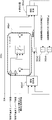
- FIG. 7 is a perspective view showing a right side recognition camera and a left side recognition camera of the on-vehicle sensors in the first embodiment.
- FIG. 5 is a perspective view showing a rider provided at left and right positions in front of the vehicle among the on-vehicle sensors in the first embodiment.
- FIG. 5 is an overall block diagram showing a target path corrector included in the navigation control unit in the first embodiment.
- FIG. 5 is a detailed block diagram showing a lateral correction amount calculation unit of the target path correction device shown in FIG. 4; FIG.
- FIG. 6 is a detailed block diagram showing a rate limiter unit in the horizontal correction amount calculation unit shown in FIG. 5;
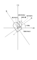
- FIG. 14 is an explanatory view showing a map coordinate system, a vehicle coordinate system, a direction, a latitudinal component and a light direction component of a lateral correction amount in the map coordinate system, and a lateral component and a longitudinal component of a lateral correction amount in the vehicle coordinate system.
- Target route comparison explanatory view showing a comparison of target route TL1 (before correction), target route TL2 (after correction, vehicle attitude disregard) and target route TL3 (after correction, vehicle attitude consideration) generated at an intersection not having a white line It is.
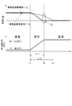
- Lateral correction amount change characteristics and target route TL3 (after correction, vehicle attitude) compared with target route TL2 (after correction, vehicle attitude neglect) and target route TL3 (after correction, vehicle attitude consideration) at an intersection not having a white line 7 is a time chart showing change characteristics of a vehicle attitude angle (direction) according to (considered).
- the position error correction method and the position error correction device use the target route information generated by the navigation control unit, and the automatically driven vehicle (steering / driving / braking is automatically controlled by selection of the automatic driving mode) It applies to an example of a support vehicle.
- the configuration of the first embodiment will be described as “overall system configuration”, “detailed configuration of navigation control unit”, “overall configuration of target path corrector”, “detailed configuration of lateral correction amount calculation unit”, “rate limiter unit Detailed description will be made separately.
- FIG. 1 shows an automatic driving control system to which the position error correction method and the position error correction device of the first embodiment are applied.
- FIG. 2 shows a right side recognition camera and a left side recognition camera of the on-vehicle sensors
- FIG. 3 shows riders provided at left and right positions in front of the vehicle of the on-vehicle sensors. The overall system configuration will be described below based on FIGS. 1 to 3.
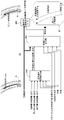
- the automatic driving control system includes an on-vehicle sensor 1, an ambient environment recognition unit 2, a navigation control unit 3, an automatic driving control unit 4, and an actuator 5.
- the surrounding environment recognition unit 2, the navigation control unit 3, and the automatic driving control unit 4 are computers that include arithmetic processing units such as a CPU and execute arithmetic processing.
- the on-vehicle sensor 1 is a sensor that is mounted on an autonomous driving vehicle and acquires peripheral information of the vehicle. It has a front recognition camera 11, a rear recognition camera 12, a right side recognition camera 13, a left side recognition camera 14, a rider 15, and a radar 16.
- a vehicle speed sensor, a gyro sensor, a blinker switch, etc. out of the figure are provided as sensors etc. which acquire information required for automatic driving control other than the surrounding information of the own vehicle.
- An ambient recognition camera (AVM: around view monitor) is configured by combining the forward recognition camera 11, the backward recognition camera 12, the right side recognition camera 13, and the left side recognition camera 14.
- AVM around view monitor
- the object on the road on the vehicle / object on the road outside the vehicle road structure, leading vehicle, following vehicle, oncoming vehicle, oncoming vehicle, surrounding vehicle, pedestrian, bicycle, two-wheeled vehicle
- Road boundaries, stop lines, pedestrian crossings, road signs (speed limit), etc. are detected.
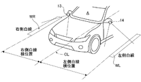
- the right side recognition camera 13 is a fisheye camera built in the right side door mirror as shown in FIG. 2 and has a right side white line lateral position detection function.
- the left side recognition camera 14 is a fisheye camera built in the left side door mirror as shown in FIG. 2 and has a left white line lateral position detection function.
- the right side white line lateral position means the length from the position of the vehicle width direction center line CL of the vehicle A to the inner end position of the right side white line WR.
- the left side white line lateral position means the length from the position of the vehicle width direction center line CL of the vehicle A to the inner end position of the left side white line WL.
- the right side white line WR and the left side white line WL are left and right lane boundaries, and the right side white line lateral position and the left side white line lateral position are taken as the left and right lane boundary detection results.
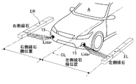
- the rider 15 and the radar 16 are disposed at the front end position of the vehicle with the irradiation axis of the output wave directed to the front of the vehicle and receive the reflected wave to detect the presence of an object in front of the vehicle. Detect the distance to the object.
- a rider / radar is configured by combining two types of distance measurement sensors, the rider 15 and the radar 16, and, for example, a laser radar, a millimeter wave radar, an ultrasonic radar, a laser range finder, etc. can be used. With the rider 15 and the radar 16, the position and objects of the vehicle on the road and objects outside the vehicle (road structures, leading vehicles, following vehicles, oncoming vehicles, oncoming vehicles, pedestrians, bicycles, two-wheelers) etc. Detect the distance of
- the rider 15 is provided at the front end left and right position of the vehicle A so as to be able to swing downward rightward and downward leftward downward, and detects right curb lateral position detection function and left curb lateral position detection function And.
- the right side curb lateral position refers to the length from the position of the vehicle width direction center line CL of the vehicle A to the inner end position of the right side curb ER.
- the left side curb lateral position refers to the length from the position of the vehicle width direction center line CL of the vehicle A to the inner end position of the left side curb EL.
- the right side curb ER and the left side curb EL are road ends on the left and right sides, and positions that are a predetermined distance inward from the right side curb lateral position and a predetermined distance inward from the left white line lateral position are taken as lane boundary detection results.
- the surrounding environment recognition unit 2 inputs image data from each recognition camera 11, 12, 13, 14 and object data from the rider / radar 15, 16.
- the surrounding environment recognition unit 2 includes a calibration processing unit 21 that generates calibration data of image data and object data, and an object recognition processing unit 22 that performs object recognition processing based on the calibration data.
- the calibration processing unit 21 estimates parameters of the image data from the recognition cameras 11, 12, 13, 14 and parameters of the object data from the rider / radar 15, 16 and uses the parameters to generate image data or an object. Generate and output calibration data of data. For example, in the case of image data from each of the recognition cameras 11, 12, 13, 14, parameters are used to correct the optical axis and lens distortion.
- the object recognition processing unit 22 receives the calibration data from the calibration processing unit 21, performs object recognition processing based on the calibration data, and outputs recognition result data.
- the object recognition processing unit 22 compares, for example, the image data and the object data, and when it is confirmed that the object exists at the position of the object candidate based on the image data, the object recognition processing unit 22 recognizes the presence of the object. Recognize what the object is.
- the navigation control unit 3 inputs the vehicle position information from the GNSS antenna 31, combines the map data including the road information and the GPS (Global Positioning System) using satellite communication, and searches from the current position to the destination by route search Generate a target route for Then, the generated target route is displayed on the map, and the target route information is output.
- GPS Global Positioning System
- GNSS Global Navigation Satellite System: Global Navigation Satellite System
- GPS Global Positioning System
- the automatic driving control unit 4 receives the recognition result data from the object recognition processing unit 22 of the surrounding environment recognition unit 2 and the target route information from the navigation control unit 3. Then, based on the input information, a target vehicle speed, a target acceleration and a target deceleration are generated. Furthermore, the drive control command value is calculated from the generated target acceleration, and the calculation result is output to the drive actuator 51. A braking control command value is calculated based on the generated target deceleration, and the calculation result is output to the braking actuator 52. The steering angle control command value is calculated based on the input target route information, and the calculation result is output to the steering angle actuator 53.
- the actuator 5 has a drive actuator 51, a braking actuator 52, and a steering angle actuator 53.
- the drive actuator 51 is an actuator that receives a drive control command value from the automatic operation control unit 4 and controls the drive source drive force. That is, in the case of an engine car, an engine actuator is used. In the case of a hybrid vehicle, an engine actuator and a motor actuator are used. In the case of an electric vehicle, a motor actuator is used.
- the braking actuator 52 is an actuator that receives a braking control command value from the automatic operation control unit 4 and controls the braking force.
- a hydraulic booster, an electric booster, or the like is used as the brake actuator 52.
- the steering angle actuator 53 is an actuator that receives a steering angle control command value from the automatic operation control unit 4 and controls the turning angle of the steered wheels.
- a steering angle control motor or the like is used as the steering angle actuator 53.
- the navigation control unit 3 includes GNSS antennas 31, 31, a position information processing unit 32, a destination setting unit 33, a map data storage unit 34, a route search processing unit 35, and a target route.
- a corrector 36 and a display device 37 are provided.
- the GNSS antennas 31, 31 are attached to the front and rear positions of the own vehicle to acquire direction information which is a vehicle posture angle of the own vehicle in the positional relationship.
- yaw rate information is acquired based on sensor information from an on-vehicle gyro sensor, and directional information is interpolated by using the acquired yaw rate information as a component.
- the position information processing unit 32 performs detection processing of the latitude / longitude of the stop position of the vehicle and the traveling position of the vehicle based on the satellite communication information input from the GNSS antennas 31 and 31.
- the vehicle position information from the position information processing unit 32 is output to the route search processing unit 35.
- the destination setting unit 33 performs input setting of the destination of the vehicle by a touch panel operation on the display screen of the display device 37 by the driver or the like.
- the destination information from the destination setting unit 33 is output to the route search processing unit 35.
- the map data storage unit 34 is a storage unit of so-called electronic map data in which the latitude and longitude are associated with the map information.
- the map data has road information associated with each point, and the road information is defined by nodes and links connecting the nodes.
- the road information includes information specifying the road by the position / area of the road, the road type for each road, the road width for each road, and the shape information of the road.
- the road information associates and stores information on the position of the intersection, the approach direction of the intersection, the type of the intersection, and other intersections for each identification information of each road link.
- the road information includes road type, road width, road shape, whether to go straight, whether to advance, whether to overtake (possibility of entering an adjacent lane), speed limit, etc. for each identification information of each road link. Corresponds and stores information on roads in
- the route search processing unit 35 includes the vehicle position information from the position information processing unit 32, the destination information from the destination setting unit 33, and the road map information (road map data) from the map data storage unit 34. input. Then, a target route is generated by route cost calculation or the like based on the road map information.
- the target route may be generated using GPS and a map, but instead of using GPS and a map, when a preceding vehicle is present, the traveling route of the preceding vehicle may be used as the target route. In this case, when the positional accuracy of the GPS is low, by using the travel locus as the target route, the amount of lateral and parallel movement in the target route correction unit 36 described later can be small, and the vehicle behavior can be smoother.
- the target path correction unit 36 inputs the recognition result data from the object recognition processing unit 22 and the target path from the route search processing unit 35. Other than the target route, information such as white line lateral distance (left and right), stationary object lateral distance (left and right), curb lateral distance (left and right), usage status of turn signal (winker) by driver, lane change status, vehicle speed etc. Enter Based on the input information, the lane boundary of the lane in which the vehicle travels is detected. Then, the positional relationship between the detected lane boundary and the target route on the map is compared, and if the target route exists within a predetermined distance with respect to the lane boundary, or the target route is with the vehicle relative to the lane boundary If it is on the opposite side, the target path is corrected by lateral translation.
- the "predetermined distance” is a distance that gives the driver a sense of apprehension when the vehicle approaches the lane boundary, and, for example, about 2 m from the center line of the vehicle's width direction to the lane boundary ( The distance from the side of the vehicle to the lane boundary is approximately 1 m.
- the target route is corrected by parallel movement in the lateral direction regardless of the distance to the vehicle.
- the display device 37 inputs the map data information from the map data storage unit 34 and the target route information from the target route corrector 36. Then, the map, the road, the target route, the vehicle position and the destination are displayed on the display screen. That is, the display device 37 provides vehicle position visual information such as where the vehicle is moving on the map during traveling by automatic driving.
- FIG. 4 shows a target path corrector 36 included in the navigation control unit 3 (controller) in the first embodiment.
- the overall configuration of the target path correction unit 36 will be described below based on FIG.
- the target route correction unit 36 sets a navigation error that occurs between the vehicle position and the target route when the vehicle position detected using the navigation information is superimposed on the map information while traveling by automatic driving, Correct by horizontal and parallel movement.
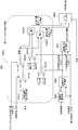
- the target route correction unit 36 includes a road boundary information integration unit 361 (lane boundary detection unit), a horizontal correction amount calculation unit 362, and a horizontal parallel movement unit 363.
- the road boundary information integration unit 361 is a white line lateral distance (left and right), a stationary object lateral distance (left and right), a curb lateral distance (left and right), a use condition of a turn indicator (winker) by a driver, a lane change condition, a vehicle speed Enter information such as Then, the lane boundary of the lane in which the host vehicle A travels is detected, and the lateral distance (left and right) between the host vehicle A and the lane boundary is output to the lateral correction amount calculation unit 362.
- the lateral correction amount calculation unit 362 includes the target route from the route search processing unit 35, the lane boundary lateral distance (left and right) from the road boundary information integration unit 361, the use status of the turn signal by the driver, the lane change status, Input information such as vehicle speed and direction. Then, the positional relationship between the detected lane boundary and the target route on the map is compared, and if the target route exists within a predetermined distance with respect to the lane boundary, or if the target route is the vehicle A with the lane boundary Calculates the lateral correction amount of the target route when it exists on the opposite side.
- the horizontal parallel movement unit 363 inputs the target path from the route search processing unit 35 and the horizontal correction amount from the horizontal correction amount calculation unit 362. Then, when the horizontal correction amount is calculated, as shown in the lower right frame B of FIG. 4, the target route is corrected by the horizontal parallel displacement by the horizontal correction amount to generate a new target route.
- the lateral and parallel movement correction of the target route when the traveling direction of the host vehicle A and the target route are deviated, the matching between the traveling direction of the host vehicle A and the new target route is enhanced.
- FIG. 5 shows the lateral correction amount calculation unit 362 of the target path correction unit 36.
- the detailed configuration of the lateral correction amount calculating unit 362 will be described based on FIG.
- the horizontal correction amount calculation unit 362 includes a horizontal deviation calculation unit 362a, a positional relationship understanding unit 362b, a horizontal correction amount calculation unit 362c, a change rate maximum value determination unit 362d, and a rate limiter 362e. And.
- the lateral deviation calculation unit 362a receives the target route from the route search processing unit 35, and calculates the lateral deviation Y0 between the target route and the vehicle.
- the positional relationship understanding unit 362 b inputs the lateral deviation Y 0 from the lateral deviation calculation unit 362 a and the lane boundary lateral distance (left and right) from the road boundary information integration unit 361. Then, the positional relationship between the target route and the lane boundary is understood (understood) by comparing the positional relationship between the target route and the lane edge. At this time, when the target route exists within a predetermined distance with respect to the lane boundary (left) or when the target route exists on the opposite side of the vehicle with respect to the lane boundary (left), the left boundary detection state Output (flag). On the other hand, when the target route exists within a predetermined distance with respect to the lane boundary (right) or when the target route exists on the opposite side of the vehicle with respect to the lane boundary (right), Output the flag).
- the lateral correction amount calculation unit 362c inputs the left boundary detection situation (flag) and the right boundary detection situation (flag) from the positional relationship understanding unit 362b, and the lane boundary lateral distance (left and right) from the road boundary information integration unit 361. Do. Then, the lateral correction amount of the target route is calculated so that the position of the target route coincides with the position of the vehicle, and the calculation result is output as a lateral correction amount target value.
- the change rate maximum value determination unit 362d inputs the use condition of the direction indicator by the driver, the lane change condition, the vehicle speed, the left boundary detection condition (flag), and the right boundary detection condition (flag). Then, the lower limit value and the upper limit value of the lateral correction amount change rate (moving speed of the target route) are determined. That is, when the change rate maximum value determination unit 362d corrects the target route by the parallel movement in the horizontal direction, the change rate maximum value determination unit 362d only specifies the moving speed (horizontal correction amount change rate) of the target route parallelly moved in the horizontal direction to a predetermined speed. Rather, it has the function of defining it variably according to the situation.
- the rate limiter unit 362 e includes a horizontal correction amount target value from the change rate maximum value determination unit 362 d, a horizontal correction amount change rate lower limit value and a horizontal correction amount change rate upper limit value from the change rate maximum value determination unit 362 d, and a direction. Enter Then, the horizontal correction amount target value is limited by the horizontal correction amount change rate (horizontal parallel movement speed of the target route) to obtain a horizontal correction amount.
- the change rate maximum value determination unit 362d includes a low vehicle speed change suppression unit 362d1, a first rate switching unit 362d2, a second rate switching unit 362d3, a third rate switching unit 362d4, and a fourth rate switching unit 362d5.
- a first rate integration unit 362d6 and a second rate integration unit 362d7 are provided.
- the low vehicle speed change suppressing portion 362d1 inputs the vehicle speed, and determines the vehicle speed corresponding change rate so as to decrease the moving speed of the target route according to the vehicle speed decrease, when the vehicle speed of the own vehicle decreases. Then, when the vehicle stops, the change rate corresponding to the vehicle speed is made zero.
- the first rate switching unit 362d2 uses the lane change situation as a trigger to select a vehicle speed-compatible change rate in a normal traveling scene without a lane change, and switches the change rate to zero when the lane change situation is input.
- the third rate switching unit 362d4 uses the right boundary detection state (flag) as a trigger to switch between a large rate (fixed value) and a small rate (fixed value).
- the fourth rate switching unit 362d5 uses the left boundary detection state (flag) as a trigger to switch between a large rate (fixed value) and a small rate (fixed value).
- the first rate integration unit 362d6 receives the change rate from the second rate switching unit 362d3 and the change rate from the third rate switching unit 362d4, and calculates the lateral correction amount change rate upper limit value by integrating both change rates. .
- the second rate integration unit 362d7 receives the change rate from the second rate switching unit 362d3 and the change rate from the fourth rate switching unit 362d5, and calculates the lateral correction amount change rate upper limit value by integrating both change rates. .
- the change rate maximum value determination unit 362d controls the moving speed (change rate) when correcting the target route by the horizontal parallel movement, as listed below.
- rate limiter section 6 shows the rate limiter unit 362e of the lateral correction amount calculation unit 362 shown in FIG. 5, and FIG. 7 shows the map coordinate system, the vehicle coordinate system, the direction, etc. necessary to explain the rate limiter unit 362e. .
- the detailed configuration of the rate limiter unit 362e will be described below with reference to FIGS. 6 and 7.
- the rate limiter unit 362e includes a rate limiter 362e1, a rotation conversion unit 362e2, an X direction correction amount readout unit 362e3, a Y direction correction amount readout unit 362e4, a rotation inverse conversion unit 362e5, and the like. And a correction amount reducing unit 362e6.
- the rate limiter 362e1 includes a lateral correction amount change rate upper limit value, a lateral correction amount change rate lower limit value, a lateral correction amount target value calculated by AVM or the like, and a lateral correction amount according to the direction from the rotation inverse conversion unit 362e5. input. Then, the final horizontal correction amount is output by limiting the horizontal correction amount target value by the change rate upper limit value, the change rate lower limit value, and the horizontal correction amount according to the direction.
- the rotation conversion unit 362e2 inputs the direction, the horizontal correction amount from the rate limiter 362e1, and the vertical correction amount (longitudinal component of the horizontal correction amount) from the vertical correction amount reduction unit 362e6. Then, as shown in FIG. 7, the lateral correction amount from the rate limiter 362e1 is rotationally converted to the map coordinate system using the direction as shown in FIG. 7, and the X direction correction amount in the map coordinate system (longitude of lateral correction amount The direction component) and the Y direction correction amount (latitude direction component of the horizontal correction amount) are output.
- the X-direction correction amount reading unit 362e3 inputs the X-direction correction amount (longitudinal component of the horizontal correction amount) in the map coordinate system from the rotation conversion unit 362e2. Then, the X-direction correction amount (longitudinal component of the horizontal correction amount) one step before is read out.
- the Y direction correction amount readout unit 362 e 4 inputs the Y direction correction amount (latitude direction component of the horizontal correction amount) in the map coordinate system from the rotation conversion unit 362 e 2. Then, the Y-direction correction amount (latitude direction component of the horizontal correction amount) one step before is read out.
- the rotation inverse conversion unit 362e5 inputs the direction, the X direction correction amount one step earlier (longitudinal direction component of the horizontal correction amount), and the Y direction correction amount one lateral step (latitude direction component of the horizontal correction amount) Do. Then, the horizontal correction amount by the map coordinate system is reversely converted to the vehicle coordinate system using the direction, and the horizontal correction amount (horizontal component in the vehicle coordinate system) and the vertical correction amount (vehicle coordinate system) in the vehicle coordinate system Output the vertical component) of
- the vertical correction amount reducing unit 362e6 receives the vertical correction amount (longitudinal component in the vehicle coordinate system) from the rotation inverse conversion unit 362e5, and gradually reduces the vertical correction amount reduced by a reduction coefficient of less than 1 as the rotation conversion unit 362e2 Output to
- the operation of the first embodiment is divided into “position error correction operation in the comparative example” and “position error correction operation in the first embodiment”.
- FIG. 8 shows a comparison of a target route TL1 (before correction) and a target route TL2 (after correction, vehicle attitude neglect) generated at an intersection having no white line.
- FIG. 9 shows a lateral correction amount change characteristic which is compared between the target route TL2 (after correction, vehicle attitude neglect) and the target route TL3 (after correction, vehicle attitude consideration) at an intersection not having a white line.
- the position error correction operation in the comparative example will be described based on FIGS. 8 and 9.
- lateral movement correction is performed on the target route TL1 before correction, but the direction is not included in the input information and the vehicle attitude is ignored.
- the GPS positional deviation is deviated by a fixed value in either direction when viewed in the map coordinate system for a short time.
- the normal component of the traveling direction of the vehicle can be corrected by various sensors, but the traveling direction is difficult because the information is scarce.
- a lateral correction amount the normal direction component
- a road boundary can not be obtained because there is usually no white line inside the intersection, and the traveling direction also changes, so the correction is not properly performed.
- the target route TL2 after correction is corrected with respect to the target route TL1 before correction as shown in FIG.
- the curvature changing portion is greatly expanded to the outside of the curve.
- FIG. 8 shows a comparison of a target route TL1 (before correction), a target route TL2 (after correction, vehicle attitude neglected) and a target route TL3 (after correction, vehicle attitude consideration) generated at an intersection having no white line.
- FIG. 9 shows a lateral correction amount change characteristic and a target route TL3 (corrected in comparison with a target route TL2 (after correction, vehicle attitude neglected) and a target route TL3 (after correction, vehicle attitude taken into consideration) at an intersection not having a white line. Later, the change characteristic of the vehicle attitude angle (direction) according to the vehicle attitude consideration is shown.
- the position error correction operation in the first embodiment will be described based on FIGS. 6, 8 and 9.
- the operation of calculating the lateral correction amount according to the direction in the rate limiter unit 362e will be described.
- the lateral correction amount change rate upper limit value, the lateral correction amount change rate lower limit value, the lateral correction amount target value calculated by AVM or the like, and the lateral correction amount according to the direction from the rotation inverse conversion unit 362e5 are It is input.
- the final horizontal correction amount is output.
- the lateral correction amount according to the direction from the rotation inverse conversion unit 362e5 is obtained by the following processing.
- the direction, the horizontal correction amount from the rate limiter 362e1, and the vertical correction amount (longitudinal component of the horizontal correction amount) from the vertical correction amount reduction unit 362e6 are input.
- the lateral correction amount by the vehicle coordinate system from the rate limiter 362e1 is rotationally converted to the map coordinate system using the direction, and the X direction correction amount (longitudinal component of the lateral correction amount) and the Y direction correction in the map coordinate system
- the amount (latitude component of the horizontal correction amount) is output.
- the X direction correction amount reading unit 362e3 the X direction correction amount (longitudinal component of the horizontal correction amount) in the map coordinate system is input from the rotation conversion unit 362e2, and the X direction correction amount one step earlier (longitude of the horizontal correction amount) Direction component) is read out.
- the Y direction correction amount reading unit 362e4 the Y direction correction amount (latitude direction component of the horizontal correction amount) in the map coordinate system is input from the rotation conversion unit 362e2, and the Y direction correction amount one step earlier (latitude of the horizontal correction amount) Direction component) is read out.
- the rotation inverse conversion unit 362e5 the direction, the X direction correction amount one step before (longitudinal direction component of the horizontal correction amount), and the Y direction correction amount one step previous (latitude direction component of the horizontal correction amount) Is input.
- the horizontal correction amount by the map coordinate system is reversely converted to the vehicle coordinate system using the direction, and the horizontal correction amount (horizontal component in the vehicle coordinate system) and the vertical correction amount (vehicle coordinate system) in the vehicle coordinate system Vertical component) is output.
- the vertical correction amount reducing unit 362e6 the vertical correction amount (vertical direction component in the vehicle coordinate system) is input from the rotation inverse conversion unit 362e5, and the vertical correction amount gradually decreased by a reduction coefficient less than 1 is rotated. It is output to the conversion unit 362e2.
- the lateral correction amount is handled by both the longitudinal component and the latitudinal component in the map coordinate system. Then, when changing the lateral movement speed of the target route according to the direction of the vehicle, the horizontal correction amount in the vehicle coordinate system is converted to rotation on the map coordinate system according to the direction. At this time, the normal direction of the traveling direction of the vehicle coordinate system Only the transverse component which is the component is updated, and the longitudinal component which is the traveling direction component is invariable. Thereafter, reverse rotation transformation is performed to return the map coordinate system to the vehicle coordinate system.
- the lateral correction amount in a certain control step is stored in the X, Y coordinate system which is a map coordinate system.
- the X-direction component and the Y-direction component are read out and converted into longitudinal and lateral components in the vehicle coordinate system by performing reverse rotation conversion by the vehicle attitude angle (direction) in the step. Then, it is compared with the target lateral correction amount value newly obtained using the lane boundary detection result, and the final lateral correction amount in that step is calculated. Then, the rotational correction is performed again by the vehicle attitude angle (direction) to calculate the lateral correction amount in the X, Y coordinate system. This process is repeated.
- the target route TL3 after correction is corrected with respect to the target route TL1 before correction.
- the curvature changing portion is suppressed from expanding outward on the curve.
- a controller (navigation control unit 3) that corrects an error that occurs between the vehicle position and the target route during driving assistance traveling (during automatic driving traveling).
- the position error correction method of the driving support vehicle automated driving vehicle
- the lateral correction amount target value of the target route is calculated by comparing the positional relationship between the detected lane boundary and the target route on the map.
- the lateral correction amount is calculated by changing the lateral movement speed of the target route for obtaining the lateral correction amount target value according to the direction that is the vehicle attitude angle of the host vehicle.
- the target path is corrected by moving it in parallel in the lateral direction by the amount of horizontal correction (FIG. 8).
- the lateral correction amount is handled by both the longitudinal component and the latitudinal component viewed in the map coordinate system.
- the horizontal correction amount by the vehicle coordinate system is converted to rotation on the map coordinate system by the direction.
- the normal direction component of the traveling direction of the vehicle coordinate system Only a certain horizontal component is updated, and a vertical component which is a traveling direction component is invariable.
- reverse rotation transformation is performed to return the map coordinate system to the vehicle coordinate system (FIG. 6).
- the lateral correction amount in a certain control step is stored in the map coordinate system X, Y coordinate system, and in the next step the X direction component and Y
- the direction component is read, reverse rotation conversion is performed by the vehicle attitude angle (direction) at that step, and converted to the vertical and horizontal components in the vehicle coordinate system, and compared with the lateral correction amount target value newly obtained using the lane boundary detection result.
- the final lateral correction amount in the step is calculated, and rotational conversion is again performed by the vehicle attitude angle (direction) to calculate the lateral correction amount in the X, Y coordinate system (FIG. 6). Therefore, in addition to the effect of (2), the calculation process is repeatedly executed in traveling on a curved road whose direction changes as time passes, thereby achieving a change in vehicle attitude angle with good responsiveness on the curved road. be able to.
- the direction information which is the vehicle attitude angle of the own vehicle is acquired in the positional relationship by attaching two GNSS antennas 31, 31 to the own vehicle.
- yaw rate information is acquired based on sensor information from an on-vehicle gyro sensor, and direction information is interpolated by component of the acquired yaw rate information (FIG. 1). For this reason, in addition to the effects of (1) to (4), even when the GPS reception condition is deteriorated, the correction by the horizontal parallel movement using the direction can be continued.
- a controller (navigation control unit 3) is provided that corrects an error that occurs between the vehicle position and the target route during driving assistance traveling (during automatic driving traveling).
- the controller has a target route correction unit 36 that corrects the target route.
- the target route correction unit 36 includes a lane boundary detection unit (road boundary information integration unit 361), a lateral correction amount calculation unit 362, and a lateral parallel movement unit 363.
- the lane boundary detection unit (road boundary information integration unit 361) detects the lane boundary of the lane in which the vehicle travels.
- the horizontal correction amount calculation unit 362 calculates the horizontal correction amount target value of the target route by comparing the positional relationship between the lane boundary detection result and the target route on the map, and obtains the horizontal correction amount target value.
- the lateral correction amount is calculated by changing the lateral movement speed according to the direction that is the vehicle attitude angle of the host vehicle.
- the horizontal parallel movement unit 363 corrects the target path by moving in parallel in the horizontal direction by the horizontal correction amount (FIG. 4). For this reason, even at an intersection where there is no white line or pedestrian crossing, a position error correction device for a driving support vehicle (autonomously driven vehicle) is provided that brings the vehicle position after passing the intersection by turning Can.
- the horizontal correction amount is calculated, and only the correction of the target route by the horizontal parallel movement is performed.
- the vertical correction is performed to parallelly move the target route in the vertical direction by the vertical component. It is good. By adding this vertical correction, the distance to the stop line can be calculated more accurately from the map information, and a smoother stop can be achieved.
- the navigation control unit 3 is used as a controller that generates a target route from the current position of the vehicle to the destination.
- a controller that generates a target route from the current position of the host vehicle to the destination an example may be taken as an automatic driving control unit.
- the target route generation function may be divided into two, a part may be divided by the navigation control unit, and the remaining part may be divided by the automatic driving control unit.
- the first embodiment shows an example in which the position error correction method and the position error correction device of the present disclosure are applied to an automatically driven vehicle in which steering / driving / braking is automatically controlled by selection of the automatic driving mode.
- the position error correction method and the position error correction device according to the present disclosure may be a driving support vehicle that supports part of driving among steering driving / driving driving / braking driving by a driver.
- the present invention can be applied to any vehicle that assists the driver in driving by correcting the position error by the navigation system.
Abstract
Description
この運転支援車両の位置誤差補正方法において、自車が走行する車線の車線境界を検出する。
検出した車線境界と地図上における目標経路との位置関係を比較することで目標経路の横補正量目標値を算出する。
横補正量目標値を得る目標経路の横移動速度を、自車の車両姿勢角である方角によって変化させることで横補正量を算出する。
目標経路を、横補正量の分だけ横方向に並行移動させることにより補正する。 In order to achieve the above object, the present disclosure includes a controller that corrects an error that occurs between the vehicle position and the target route during driving assistance traveling.
In this position error correction method for a driving assistance vehicle, the lane boundary of the lane in which the vehicle travels is detected.
The lateral correction amount target value of the target route is calculated by comparing the positional relationship between the detected lane boundary and the target route on the map.
The lateral correction amount is calculated by changing the lateral movement speed of the target route for obtaining the lateral correction amount target value according to the direction that is the vehicle attitude angle of the host vehicle.
The target path is corrected by moving in parallel in the lateral direction by the amount of horizontal correction.
実施例1における位置誤差補正方法及び位置誤差補正装置は、ナビゲーション制御ユニットにて生成される目標経路情報を用い、自動運転モードの選択により操舵/駆動/制動が自動制御される自動運転車両(運転支援車両の一例)に適用したものである。以下、実施例1の構成を、「全体システム構成」、「ナビゲーション制御ユニットの詳細構成」、「目標経路補正器の全体構成」、「横補正量算出部の詳細構成」、「レートリミッタ部の詳細構成」に分けて説明する。 First, the configuration will be described.
The position error correction method and the position error correction device according to the first embodiment use the target route information generated by the navigation control unit, and the automatically driven vehicle (steering / driving / braking is automatically controlled by selection of the automatic driving mode) It applies to an example of a support vehicle. Hereinafter, the configuration of the first embodiment will be described as “overall system configuration”, “detailed configuration of navigation control unit”, “overall configuration of target path corrector”, “detailed configuration of lateral correction amount calculation unit”, “rate limiter unit Detailed description will be made separately.
図1は、実施例1の位置誤差補正方法及び位置誤差補正装置が適用された自動運転制御システムを示す。図2は、車載センサのうち右側方認識カメラ及び左側方認識カメラを示し、図3は、車載センサのうち車両前方の左右位置に設けられたライダーを示す。以下、図1~図3に基づいて全体システム構成を説明する。 [Whole system configuration]
FIG. 1 shows an automatic driving control system to which the position error correction method and the position error correction device of the first embodiment are applied. FIG. 2 shows a right side recognition camera and a left side recognition camera of the on-vehicle sensors, and FIG. 3 shows riders provided at left and right positions in front of the vehicle of the on-vehicle sensors. The overall system configuration will be described below based on FIGS. 1 to 3.
なお、右側白線横位置とは、自車Aの車幅方向中心線CLの位置から右側白線WRの内端位置までの長さをいう。左側白線横位置とは、自車Aの車幅方向中心線CLの位置から左側白線WLの内端位置までの長さをいう。なお、右側白線WRと左側白線WLは、左右の車線境界であり、右側白線横位置と左側白線横位置は、左右の車線境界検出結果とされる。 The right
The right side white line lateral position means the length from the position of the vehicle width direction center line CL of the vehicle A to the inner end position of the right side white line WR. The left side white line lateral position means the length from the position of the vehicle width direction center line CL of the vehicle A to the inner end position of the left side white line WL. The right side white line WR and the left side white line WL are left and right lane boundaries, and the right side white line lateral position and the left side white line lateral position are taken as the left and right lane boundary detection results.
目的地を設定し、最適な目標経路を演算し、自動運転用の目標経路を表示するナビゲーション制御ユニット3の詳細構成を、図1に基づいて説明する。 [Detailed configuration of navigation control unit]
The detailed configuration of the navigation control unit 3 that sets a destination, calculates an optimum target route, and displays a target route for automatic driving will be described based on FIG.
図4は、実施例1においてナビゲーション制御ユニット3(コントローラ)に有する目標経路補正器36を示す。以下、図4に基づいて目標経路補正器36の全体構成を説明する。 [Overall Configuration of Target Path Corrector]
FIG. 4 shows a
図5は、目標経路補正器36のうち横補正量算出部362を示す。以下、図5に基づいて横補正量算出部362の詳細構成を説明する。 [Detailed Configuration of Horizontal Correction Amount Calculation Unit 362]
FIG. 5 shows the lateral correction
つまり、変化レート最大値決定部362dは、目標経路を横方向の並行移動により補正する際、横方向に並行移動させる目標経路の移動速度(横補正量変化レート)を、所定速度に規定するだけではなく、状況に応じて可変に規定する機能を有する。 The change rate maximum
That is, when the change rate maximum
図6は、図5に示す横補正量算出部362のうちレートリミッタ部362eを示し、図7は、レートリミッタ部362eを説明するのに必要な地図座標系と車両座標系と方角などを示す。以下、図6及び図7に基づいて、レートリミッタ部362eの詳細構成を説明する。 [Detailed configuration of rate limiter section]
6 shows the
実施例1の作用を、「比較例での位置誤差補正作用」、「実施例1での位置誤差補正作用」に分けて説明する。 Next, the operation will be described.
The operation of the first embodiment is divided into “position error correction operation in the comparative example” and “position error correction operation in the first embodiment”.
図8は、白線を有さない交差点で生成される目標経路TL1(補正前)・目標経路TL2(補正後、車両姿勢無視)の比較を示す。図9は、白線を有さない交差点での目標経路TL2(補正後、車両姿勢無視)と目標経路TL3(補正後、車両姿勢考慮)とで比較した横補正量変化特性を示す。以下、図8及び図9に基づいて比較例での位置誤差補正作用を説明する。 [Position error correction action in the comparative example]
FIG. 8 shows a comparison of a target route TL1 (before correction) and a target route TL2 (after correction, vehicle attitude neglect) generated at an intersection having no white line. FIG. 9 shows a lateral correction amount change characteristic which is compared between the target route TL2 (after correction, vehicle attitude neglect) and the target route TL3 (after correction, vehicle attitude consideration) at an intersection not having a white line. Hereinafter, the position error correction operation in the comparative example will be described based on FIGS. 8 and 9.
これに対し、比較例のように、法線方向成分のみを取扱い(横補正量と呼ぶ)、道路境界情報より更新を行うことも考えられる。しかし、交差点で右左折を行う際、交差点内では通常白線が無いため、道路境界が得られず、進行方向も変わってしまうため、正しい補正が行われない。 The GPS positional deviation is deviated by a fixed value in either direction when viewed in the map coordinate system for a short time. However, when trying to correct this, the normal component of the traveling direction of the vehicle can be corrected by various sensors, but the traveling direction is difficult because the information is scarce.
On the other hand, as in the comparative example, it is also conceivable to handle only the normal direction component (referred to as a lateral correction amount) and to perform updating from the road boundary information. However, when turning to the left or right at an intersection, a road boundary can not be obtained because there is usually no white line inside the intersection, and the traveling direction also changes, so the correction is not properly performed.
図8は、白線を有さない交差点で生成される目標経路TL1(補正前)・目標経路TL2(補正後、車両姿勢無視)・目標経路TL3(補正後、車両姿勢考慮)の比較を示す。図9は、白線を有さない交差点での目標経路TL2(補正後、車両姿勢無視)と目標経路TL3(補正後、車両姿勢考慮)とで比較した横補正量変化特性と目標経路TL3(補正後、車両姿勢考慮)による車両姿勢角(方角)の変化特性を示す。以下、図6、図8及び図9に基づいて実施例1での位置誤差補正作用を説明する。 [Position error correction operation in the first embodiment]
FIG. 8 shows a comparison of a target route TL1 (before correction), a target route TL2 (after correction, vehicle attitude neglected) and a target route TL3 (after correction, vehicle attitude consideration) generated at an intersection having no white line. FIG. 9 shows a lateral correction amount change characteristic and a target route TL3 (corrected in comparison with a target route TL2 (after correction, vehicle attitude neglected) and a target route TL3 (after correction, vehicle attitude taken into consideration) at an intersection not having a white line. Later, the change characteristic of the vehicle attitude angle (direction) according to the vehicle attitude consideration is shown. Hereinafter, the position error correction operation in the first embodiment will be described based on FIGS. 6, 8 and 9.
実施例1における自動運転車両の位置誤差補正方法及び位置誤差補正装置にあっては、下記に列挙する効果が得られる。 Next, the effects will be described.
In the position error correction method and position error correction apparatus for an autonomous driving vehicle in the first embodiment, the following effects can be obtained.
この運転支援車両(自動運転車両)の位置誤差補正方法において、自車が走行する車線の車線境界を検出する。
検出した車線境界と地図上における目標経路との位置関係を比較することで目標経路の横補正量目標値を算出する。
横補正量目標値を得る目標経路の横移動速度を、自車の車両姿勢角である方角によって変化させることで横補正量を算出する。
目標経路を、横補正量の分だけ横方向に並行移動させることにより補正する(図8)。
このため、白線や横断歩道がない交差点であっても、交差点を右左折により通過した後の自車位置を車線内中央に近づける運転支援車両(自動運転車両)の位置誤差補正方法を提供することができる。 (1) A controller (navigation control unit 3) is provided that corrects an error that occurs between the vehicle position and the target route during driving assistance traveling (during automatic driving traveling).
In the position error correction method of the driving support vehicle (automatic driving vehicle), the lane boundary of the lane in which the vehicle travels is detected.
The lateral correction amount target value of the target route is calculated by comparing the positional relationship between the detected lane boundary and the target route on the map.
The lateral correction amount is calculated by changing the lateral movement speed of the target route for obtaining the lateral correction amount target value according to the direction that is the vehicle attitude angle of the host vehicle.
The target path is corrected by moving it in parallel in the lateral direction by the amount of horizontal correction (FIG. 8).
For this reason, even at an intersection where there are no white lines or pedestrian crossings, a method for correcting the position error of a driving support vehicle (autonomously driven vehicle) that brings the vehicle position after passing the intersection by turning right and left to the center of the lane is provided. Can.
目標経路の横移動速度を自車の方角によって変化させるとき、車両座標系による横補正量を方角により地図座標系に回転変換を行い、このとき、車両座標系の進行方向の法線方向成分である横方向成分のみを更新し、進行方向成分である縦方向成分は不変とする。
その後、地図座標系を車両座標系に戻す逆回転変換を行う(図6)。
このため、(1)の効果に加え、地図座標系上にて横補正量を値だけでなく方向をもったベクトル値として扱うことで、交差点以外のS字カーブ路走行など、より複雑な姿勢変化に対しても対処することができる。 (2) The lateral correction amount is handled by both the longitudinal component and the latitudinal component viewed in the map coordinate system.
When changing the lateral movement speed of the target route according to the direction of the vehicle, the horizontal correction amount by the vehicle coordinate system is converted to rotation on the map coordinate system by the direction. At this time, the normal direction component of the traveling direction of the vehicle coordinate system Only a certain horizontal component is updated, and a vertical component which is a traveling direction component is invariable.
Thereafter, reverse rotation transformation is performed to return the map coordinate system to the vehicle coordinate system (FIG. 6).
For this reason, in addition to the effect of (1), by treating the lateral correction amount as a vector value having a direction as well as a value on the map coordinate system, more complex postures such as traveling on S-curved roads other than intersections It can also cope with changes.
このため、(2)の効果に加え、時間の経過と共に方角が変化するカーブ路での走行において繰り返し算出処理が実行されることにより、カーブ路で応答性の良い車両姿勢角の変化を達成することができる。 (3) When changing the lateral movement speed of the target route according to the direction of the vehicle, the lateral correction amount in a certain control step is stored in the map coordinate system X, Y coordinate system, and in the next step the X direction component and Y The direction component is read, reverse rotation conversion is performed by the vehicle attitude angle (direction) at that step, and converted to the vertical and horizontal components in the vehicle coordinate system, and compared with the lateral correction amount target value newly obtained using the lane boundary detection result. The final lateral correction amount in the step is calculated, and rotational conversion is again performed by the vehicle attitude angle (direction) to calculate the lateral correction amount in the X, Y coordinate system (FIG. 6).
Therefore, in addition to the effect of (2), the calculation process is repeatedly executed in traveling on a curved road whose direction changes as time passes, thereby achieving a change in vehicle attitude angle with good responsiveness on the curved road. be able to.
このため、(2)又は(3)の効果に加え、原則として保持している横補正量の縦方向成分を減少させていくことで、時間の経過と共に目標経路情報の縦方向のズレ量が拡大するのを抑えることができる。即ち、縦方向は車線境界(白線)の情報だけでは補正が難しく、かつ、長い時間経過してしまった場合、目標経路の縦方向ズレ量に変化があらわれる。 (4) The longitudinal component is gradually reduced as time passes (FIG. 6).
For this reason, in addition to the effect of (2) or (3), by decreasing the vertical component of the horizontal correction amount held in principle, the amount of deviation of the target route information in the vertical direction with the passage of time becomes It is possible to suppress expansion. That is, in the vertical direction, correction is difficult only with information on lane boundaries (white lines), and when a long time has elapsed, a change appears in the amount of longitudinal deviation of the target route.
GNSSアンテナ31,31による受信状況が悪化した際は、車載のジャイロセンサからのセンサ情報に基づいてヨーレート情報を取得し、取得したヨーレート情報を成分することで方角情報を補間する(図1)。
このため、(1)~(4)の効果に加え、GPS受信状況が悪化した際にも、方角を用いた横並行移動による補正を継続することができる。 (5) The direction information which is the vehicle attitude angle of the own vehicle is acquired in the positional relationship by attaching two
When the reception condition by the
For this reason, in addition to the effects of (1) to (4), even when the GPS reception condition is deteriorated, the correction by the horizontal parallel movement using the direction can be continued.
この運転支援車両(自動運転車両)の位置誤差補正装置において、コントローラ(ナビゲーション制御ユニット3)は、目標経路を補正する目標経路補正器36を有する。さらに、目標経路補正器36は、車線境界検出部(道路境界情報統合部361)と、横補正量算出部362と、横並行移動部363と、を有する。
車線境界検出部(道路境界情報統合部361)は、自車が走行する車線の車線境界を検出する。
横補正量算出部362は、車線境界の検出結果と地図上における目標経路との位置関係を比較することで目標経路の横補正量目標値を算出し、横補正量目標値を得る目標経路の横移動速度を、自車の車両姿勢角である方角によって変化させることで横補正量を算出する。
横並行移動部363は、横補正量が算出されると、目標経路を横補正量の分だけ横方向に並行移動させることにより補正する(図4)。
このため、白線や横断歩道がない交差点であっても、交差点を右左折により通過した後の自車位置を車線内中央に近づける運転支援車両(自動運転車両)の位置誤差補正装置を提供することができる。 (6) A controller (navigation control unit 3) is provided that corrects an error that occurs between the vehicle position and the target route during driving assistance traveling (during automatic driving traveling).
In the position error correction device of the driving support vehicle (autonomously driven vehicle), the controller (navigation control unit 3) has a target
The lane boundary detection unit (road boundary information integration unit 361) detects the lane boundary of the lane in which the vehicle travels.
The horizontal correction
When the horizontal correction amount is calculated, the horizontal
For this reason, even at an intersection where there is no white line or pedestrian crossing, a position error correction device for a driving support vehicle (autonomously driven vehicle) is provided that brings the vehicle position after passing the intersection by turning Can.
Claims (6)
- 運転支援走行中、自車位置と目標経路との間で生じる誤差を補正するコントローラを備える運転支援車両の位置誤差補正方法において、
自車が走行する車線の車線境界を検出し、
前記車線境界の検出結果と地図上における前記目標経路との位置関係を比較することで前記目標経路の横補正量目標値を算出し、
前記横補正量目標値を得る前記目標経路の横移動速度を、自車の車両姿勢角である方角によって変化させることで横補正量を算出し、
前記目標経路を、前記横補正量の分だけ横方向に並行移動させることにより補正する
ことを特徴とする運転支援車両の位置誤差補正方法。 In a method for correcting a position error of a driving support vehicle, the controller includes a controller that corrects an error that occurs between the vehicle position and a target route during driving assistance traveling.
Detect the lane boundary of the lane where the vehicle travels,
Calculating a lateral correction amount target value of the target route by comparing the positional relationship between the detection result of the lane boundary and the target route on the map;
The lateral correction amount is calculated by changing the lateral movement speed of the target route for obtaining the lateral correction amount target value according to a direction that is a vehicle posture angle of the host vehicle,
A method of correcting a position error of a driving support vehicle, comprising: correcting the target route by moving the target route in parallel in the lateral direction by an amount corresponding to the lateral correction amount. - 請求項1に記載された運転支援車両の位置誤差補正方法において、
前記横補正量を、地図座標系でみた経度方向成分と緯度方向成分の両方により取り扱うものであり、
前記目標経路の横移動速度を自車の方角によって変化させるとき、車両座標系による横補正量を方角により地図座標系に回転変換を行い、このとき、車両座標系の進行方向の法線方向成分である横方向成分のみを更新し、進行方向成分である縦方向成分は不変とし、
その後、地図座標系を車両座標系に戻す逆回転変換を行う
ことを特徴とする運転支援車両の位置誤差補正方法。 In the method for correcting a position error of a driving support vehicle according to claim 1,
The lateral correction amount is handled by both a longitudinal component and a latitudinal component viewed in the map coordinate system,
When changing the lateral movement speed of the target route according to the direction of the vehicle, the horizontal correction amount in the vehicle coordinate system is subjected to rotational conversion to the map coordinate system according to the direction. Update only the horizontal direction component, and keep the vertical direction component as the traveling direction component unchanged,
Thereafter, reverse rotation transformation is performed to return the map coordinate system to the vehicle coordinate system. - 請求項2に記載された運転支援車両の位置誤差補正方法において、
前記目標経路の横移動速度を自車の方角によって変化させるとき、ある制御ステップにおける横補正量を地図座標系であるX,Y座標系で記憶し、次のステップでX方向成分とY方向成分を読み出し、そのステップにおける車両姿勢角(方角)分だけ逆回転変換して車両座標系における縦横成分に変換し、新しく車線境界検出結果を用いて得られた横補正量目標値と比較し、そのステップにおける最終的な横補正量を算出し、再度、車両姿勢角(方角)分だけ回転変換してX,Y座標系での横補正量を算出する
ことを特徴とする運転支援車両の位置誤差補正方法。 In the method for correcting a position error of a driving support vehicle according to claim 2,
When changing the lateral movement speed of the target route according to the direction of the vehicle, the lateral correction amount in a control step is stored in the X, Y coordinate system which is a map coordinate system, and the X direction component and the Y direction component are obtained in the next step. Are read out, reverse rotation conversion is performed by the vehicle attitude angle (direction) in that step, and converted to vertical and horizontal components in the vehicle coordinate system, and compared with the lateral correction amount target value newly obtained using lane boundary detection results The final lateral correction amount in the step is calculated, and rotational conversion is performed again by the vehicle attitude angle (direction) to calculate the lateral correction amount in the X, Y coordinate system. Position error of the driving assistance vehicle Correction method. - 請求項2又は3に記載された運転支援車両の位置誤差補正方法において、
前記縦方向成分は、時間の経過にしたがって徐々に減少させる
ことを特徴とする運転支援車両の位置誤差補正方法。 In the method for correcting a position error of a driving support vehicle according to claim 2 or 3,
The position error correction method for a driving assistance vehicle, wherein the longitudinal component is gradually reduced as time passes. - 請求項1から4までの何れか一項に記載された運転支援車両の位置誤差補正方法において、
前記自車の車両姿勢角である方角情報は、2台のGNSSアンテナを自車に取り付けることで、その位置関係にて取得し、
前記GNSSアンテナによる受信状況が悪化した際は、車載のジャイロセンサからのセンサ情報に基づいてヨーレート情報を取得し、取得したヨーレート情報を成分することで方角情報を補間する
ことを特徴とする運転支援車両の位置誤差補正方法。 In the method for correcting a position error of a driving assistance vehicle according to any one of claims 1 to 4,
The direction information, which is the vehicle attitude angle of the vehicle, is acquired in the positional relationship by attaching two GNSS antennas to the vehicle,
When the reception condition by the GNSS antenna is deteriorated, yaw rate information is acquired based on sensor information from an on-vehicle gyro sensor, and direction information is interpolated by component of the acquired yaw rate information. Vehicle position error correction method. - 運転支援走行中、自車位置と目標経路との間で生じる誤差を補正するコントローラを備える運転支援車両の位置誤差補正装置において、
前記コントローラは、目標経路を補正する目標経路補正器を有し、
前記目標経路補正器は、
自車が走行する車線の車線境界を検出する車線境界検出部と、
前記車線境界の検出結果と地図上における前記目標経路との位置関係を比較することで前記目標経路の横補正量目標値を算出し、横補正量目標値を得る前記目標経路の横移動速度を、自車の車両姿勢角である方角によって変化させることで横補正量を算出する横補正量算出部と、
前記横補正量が算出されると、前記目標経路を前記横補正量の分だけ横方向に並行移動させることにより補正する横並行移動部と、
を有することを特徴とする運転支援車両の位置誤差補正装置。 A position error correction device for a driving support vehicle, comprising a controller that corrects an error that occurs between the vehicle position and a target route during driving assistance traveling.
The controller has a target path corrector for correcting a target path,
The target path corrector is
A lane boundary detection unit that detects the lane boundary of the lane in which the host vehicle is traveling;
The lateral movement speed of the target route is obtained by calculating the lateral correction amount target value of the target route by comparing the positional relationship between the detection result of the lane boundary and the target route on the map. A lateral correction amount calculating unit that calculates a lateral correction amount by changing the vehicle posture angle of the host vehicle according to a direction;
A horizontal parallel movement unit that corrects the target path by moving the target path in parallel by the horizontal correction amount when the horizontal correction amount is calculated;
A position error correction device for a driving assistance vehicle, comprising:
Priority Applications (10)
| Application Number | Priority Date | Filing Date | Title |
|---|---|---|---|
| CA3074414A CA3074414A1 (en) | 2017-08-30 | 2017-08-30 | Method for correcting position error and device for correcting position error in drive-assisted vehicle |
| EP17923821.7A EP3678110B1 (en) | 2017-08-30 | 2017-08-30 | Method for correcting positional error and device for correcting positional error in a drive-assisted vehicle |
| JP2019538821A JP6658978B2 (en) | 2017-08-30 | 2017-08-30 | Driving support vehicle position error correction method and position error correction device |
| RU2020112175A RU2738491C1 (en) | 2017-08-30 | 2017-08-30 | Method for correction of position error and device for correction of position error in vehicle with driving assistance |
| CN201780093971.7A CN111066071B (en) | 2017-08-30 | 2017-08-30 | Position error correction method and position error correction device for driving assistance vehicle |
| US16/641,770 US10988139B2 (en) | 2017-08-30 | 2017-08-30 | Vehicle position control method and device vehicle position control device for correcting position in drive-assisted vehicle |
| MX2020002227A MX2020002227A (en) | 2017-08-30 | 2017-08-30 | Method for correcting positional error and device for correcting positional error in driving assistance vehicle. |
| BR112020003996-9A BR112020003996A2 (en) | 2017-08-30 | 2017-08-30 | method for correcting position error and device for correcting position error in an assisted steering vehicle |
| KR1020207008649A KR20200036038A (en) | 2017-08-30 | 2017-08-30 | Position error correction method and position error correction device for driving assistance vehicles |
| PCT/JP2017/031168 WO2019043833A1 (en) | 2017-08-30 | 2017-08-30 | Method for correcting positional error and device for correcting positional error in driving assistance vehicle |
Applications Claiming Priority (1)
| Application Number | Priority Date | Filing Date | Title |
|---|---|---|---|
| PCT/JP2017/031168 WO2019043833A1 (en) | 2017-08-30 | 2017-08-30 | Method for correcting positional error and device for correcting positional error in driving assistance vehicle |
Publications (1)
| Publication Number | Publication Date |
|---|---|
| WO2019043833A1 true WO2019043833A1 (en) | 2019-03-07 |
Family
ID=65525842
Family Applications (1)
| Application Number | Title | Priority Date | Filing Date |
|---|---|---|---|
| PCT/JP2017/031168 WO2019043833A1 (en) | 2017-08-30 | 2017-08-30 | Method for correcting positional error and device for correcting positional error in driving assistance vehicle |
Country Status (10)
| Country | Link |
|---|---|
| US (1) | US10988139B2 (en) |
| EP (1) | EP3678110B1 (en) |
| JP (1) | JP6658978B2 (en) |
| KR (1) | KR20200036038A (en) |
| CN (1) | CN111066071B (en) |
| BR (1) | BR112020003996A2 (en) |
| CA (1) | CA3074414A1 (en) |
| MX (1) | MX2020002227A (en) |
| RU (1) | RU2738491C1 (en) |
| WO (1) | WO2019043833A1 (en) |
Cited By (6)
| Publication number | Priority date | Publication date | Assignee | Title |
|---|---|---|---|---|
| CN111854727A (en) * | 2019-04-27 | 2020-10-30 | 北京初速度科技有限公司 | Vehicle pose correction method and device |
| EP3786586A1 (en) * | 2019-08-28 | 2021-03-03 | Zenuity AB | Path planning for autonomous and semi-autonomous vehicles |
| CN112629544A (en) * | 2019-10-09 | 2021-04-09 | 北京初速度科技有限公司 | Vehicle positioning method and device based on lane line |
| CN113795726A (en) * | 2019-05-15 | 2021-12-14 | 日产自动车株式会社 | Self-position correction method and self-position correction device |
| KR20230057073A (en) * | 2021-10-21 | 2023-04-28 | 한국교통대학교산학협력단 | A method and apparatus for improving positioning of vehicles using LDM information and environmental sensor |
| US20230152120A1 (en) * | 2020-04-08 | 2023-05-18 | Nissan Motor Co., Ltd. | Map Information Correction Method, Driving Assistance Method, and Map Information Correction Device |
Families Citing this family (12)
| Publication number | Priority date | Publication date | Assignee | Title |
|---|---|---|---|---|
| EP3678109B1 (en) * | 2017-08-30 | 2023-05-03 | Nissan Motor Co., Ltd. | Position correction method for driving-assist vehicle and position error correction device |
| JP6985176B2 (en) * | 2018-02-16 | 2021-12-22 | 本田技研工業株式会社 | Vehicle control device |
| CN109795477B (en) * | 2019-02-22 | 2020-11-06 | 百度在线网络技术(北京)有限公司 | Method, device and storage medium for eliminating steady-state lateral deviation |
| US11904890B2 (en) * | 2020-06-17 | 2024-02-20 | Baidu Usa Llc | Lane change system for lanes with different speed limits |
| US20220080986A1 (en) * | 2020-09-16 | 2022-03-17 | Zenuity Ab | Monitoring of on-board vehicle image capturing device functionality compliance |
| KR20220065955A (en) * | 2020-11-13 | 2022-05-23 | 현대자동차주식회사 | Autonomous control apparatus for lateral motion and control method for the same |
| CN112665538B (en) * | 2020-12-09 | 2023-10-13 | 云南昆船电子设备有限公司 | Vehicle autonomous navigation transverse ranging system and method |
| CN112731320A (en) * | 2020-12-29 | 2021-04-30 | 福瑞泰克智能系统有限公司 | Method, device and equipment for estimating error data of vehicle-mounted radar and storage medium |
| CN113176779B (en) * | 2021-04-28 | 2023-05-26 | 上海布鲁可积木科技有限公司 | Control method and system for movement device, storage medium and movement device |
| CN114114369B (en) * | 2022-01-27 | 2022-07-15 | 智道网联科技(北京)有限公司 | Autonomous vehicle positioning method and apparatus, electronic device, and storage medium |
| US11919451B2 (en) | 2022-02-28 | 2024-03-05 | Nissan North America, Inc. | Vehicle data display system |
| CN115950441B (en) * | 2023-03-08 | 2023-07-07 | 智道网联科技(北京)有限公司 | Fusion positioning method and device for automatic driving vehicle and electronic equipment |
Citations (4)
| Publication number | Priority date | Publication date | Assignee | Title |
|---|---|---|---|---|
| JP2011174877A (en) | 2010-02-25 | 2011-09-08 | Mitsubishi Electric Corp | Own-vehicle position correction device |
| JP2015096824A (en) * | 2013-11-15 | 2015-05-21 | アジア航測株式会社 | Measurement point height providing system, measurement point height providing method, and measurement point height providing program |
| JP2015205635A (en) * | 2014-04-22 | 2015-11-19 | 本田技研工業株式会社 | Travel support device |
| JP2017077849A (en) * | 2015-10-22 | 2017-04-27 | 本田技研工業株式会社 | Vehicle traveling control device |
Family Cites Families (14)
| Publication number | Priority date | Publication date | Assignee | Title |
|---|---|---|---|---|
| JPS5852070A (en) | 1981-09-17 | 1983-03-28 | 日立造船株式会社 | Method of changing helicoidal silo inot mass-flow |
| JP4983132B2 (en) * | 2006-07-26 | 2012-07-25 | 株式会社デンソー | Vehicle direction identification method and vehicle direction identification device. |
| US8775063B2 (en) * | 2009-01-26 | 2014-07-08 | GM Global Technology Operations LLC | System and method of lane path estimation using sensor fusion |
| JP5862670B2 (en) * | 2011-08-02 | 2016-02-16 | 日産自動車株式会社 | Driving support device and driving support method |
| JP2016517106A (en) * | 2013-04-01 | 2016-06-09 | パク,ス−ミン | Automobile navigation system |
| JP5802241B2 (en) * | 2013-07-04 | 2015-10-28 | 富士重工業株式会社 | Vehicle driving support control device |
| JP2016084092A (en) * | 2014-10-28 | 2016-05-19 | 富士重工業株式会社 | Travel control device of vehicle |
| JP6237656B2 (en) * | 2015-01-19 | 2017-11-29 | トヨタ自動車株式会社 | Vehicle system |
| JP6350383B2 (en) * | 2015-05-01 | 2018-07-04 | トヨタ自動車株式会社 | Vehicle travel control device |
| JP6376055B2 (en) * | 2015-06-26 | 2018-08-22 | 株式会社デンソー | Lane departure control system |
| JP6815724B2 (en) * | 2015-11-04 | 2021-01-20 | トヨタ自動車株式会社 | Autonomous driving system |
| JP2017182521A (en) * | 2016-03-31 | 2017-10-05 | 日立オートモティブシステムズ株式会社 | Travel control device for vehicle |
| CN106052705A (en) | 2016-05-31 | 2016-10-26 | 惠州华阳通用电子有限公司 | Vehicle-mounted integrated navigation method and device |
| CN107085938B (en) * | 2017-06-08 | 2019-07-02 | 中南大学 | The fault-tolerant planing method of intelligent driving local path followed based on lane line and GPS |
-
2017
- 2017-08-30 CA CA3074414A patent/CA3074414A1/en not_active Abandoned
- 2017-08-30 BR BR112020003996-9A patent/BR112020003996A2/en unknown
- 2017-08-30 JP JP2019538821A patent/JP6658978B2/en active Active
- 2017-08-30 US US16/641,770 patent/US10988139B2/en active Active
- 2017-08-30 WO PCT/JP2017/031168 patent/WO2019043833A1/en unknown
- 2017-08-30 KR KR1020207008649A patent/KR20200036038A/en not_active Application Discontinuation
- 2017-08-30 MX MX2020002227A patent/MX2020002227A/en unknown
- 2017-08-30 CN CN201780093971.7A patent/CN111066071B/en active Active
- 2017-08-30 RU RU2020112175A patent/RU2738491C1/en active
- 2017-08-30 EP EP17923821.7A patent/EP3678110B1/en active Active
Patent Citations (4)
| Publication number | Priority date | Publication date | Assignee | Title |
|---|---|---|---|---|
| JP2011174877A (en) | 2010-02-25 | 2011-09-08 | Mitsubishi Electric Corp | Own-vehicle position correction device |
| JP2015096824A (en) * | 2013-11-15 | 2015-05-21 | アジア航測株式会社 | Measurement point height providing system, measurement point height providing method, and measurement point height providing program |
| JP2015205635A (en) * | 2014-04-22 | 2015-11-19 | 本田技研工業株式会社 | Travel support device |
| JP2017077849A (en) * | 2015-10-22 | 2017-04-27 | 本田技研工業株式会社 | Vehicle traveling control device |
Non-Patent Citations (1)
| Title |
|---|
| See also references of EP3678110A4 |
Cited By (11)
| Publication number | Priority date | Publication date | Assignee | Title |
|---|---|---|---|---|
| CN111854727A (en) * | 2019-04-27 | 2020-10-30 | 北京初速度科技有限公司 | Vehicle pose correction method and device |
| CN111854727B (en) * | 2019-04-27 | 2022-05-13 | 北京魔门塔科技有限公司 | Vehicle pose correction method and device |
| CN113795726A (en) * | 2019-05-15 | 2021-12-14 | 日产自动车株式会社 | Self-position correction method and self-position correction device |
| CN113795726B (en) * | 2019-05-15 | 2022-05-10 | 日产自动车株式会社 | Self-position correction method and self-position correction device |
| EP3786586A1 (en) * | 2019-08-28 | 2021-03-03 | Zenuity AB | Path planning for autonomous and semi-autonomous vehicles |
| CN112629544A (en) * | 2019-10-09 | 2021-04-09 | 北京初速度科技有限公司 | Vehicle positioning method and device based on lane line |
| CN112629544B (en) * | 2019-10-09 | 2022-12-02 | 北京魔门塔科技有限公司 | Vehicle positioning method and device based on lane line |
| US20230152120A1 (en) * | 2020-04-08 | 2023-05-18 | Nissan Motor Co., Ltd. | Map Information Correction Method, Driving Assistance Method, and Map Information Correction Device |
| US11761787B2 (en) * | 2020-04-08 | 2023-09-19 | Nissan Motor Co., Ltd. | Map information correction method, driving assistance method, and map information correction device |
| KR20230057073A (en) * | 2021-10-21 | 2023-04-28 | 한국교통대학교산학협력단 | A method and apparatus for improving positioning of vehicles using LDM information and environmental sensor |
| KR102603534B1 (en) * | 2021-10-21 | 2023-11-16 | 한국교통대학교산학협력단 | A method and apparatus for improving positioning of vehicles using LDM information and environmental sensor |
Also Published As
| Publication number | Publication date |
|---|---|
| US20200377089A1 (en) | 2020-12-03 |
| BR112020003996A2 (en) | 2020-09-01 |
| CN111066071A (en) | 2020-04-24 |
| EP3678110A1 (en) | 2020-07-08 |
| EP3678110B1 (en) | 2022-08-10 |
| MX2020002227A (en) | 2020-07-14 |
| JPWO2019043833A1 (en) | 2020-02-06 |
| JP6658978B2 (en) | 2020-03-04 |
| CN111066071B (en) | 2021-08-17 |
| US10988139B2 (en) | 2021-04-27 |
| KR20200036038A (en) | 2020-04-06 |
| EP3678110A4 (en) | 2020-09-09 |
| RU2738491C1 (en) | 2020-12-14 |
| CA3074414A1 (en) | 2019-03-07 |
Similar Documents
| Publication | Publication Date | Title |
|---|---|---|
| JP6658978B2 (en) | Driving support vehicle position error correction method and position error correction device | |
| JP6642772B2 (en) | Driving support vehicle position error correction method and position error correction device | |
| WO2019043832A1 (en) | Travel control method and travel control device for driving-assist vehicle | |
| US9862410B2 (en) | Vehicle steering control apparatus | |
| KR20190113918A (en) | Driving assistance method and driving assistance device | |
| JPWO2019008757A1 (en) | Parking assistance method and parking control device | |
| WO2019187716A1 (en) | Parking assistance device | |
| JP7059528B2 (en) | Parking support method and parking control device | |
| JP7377822B2 (en) | Driving support method and driving support device | |
| WO2018211645A1 (en) | Driving assistance method and driving assistance apparatus | |
| US11518404B2 (en) | Static-state curvature error compensation control logic for autonomous driving vehicles | |
| US11231501B2 (en) | Front and side three-LIDAR design for autonomous driving vehicles | |
| WO2023042731A1 (en) | Parking route generation device | |
| US20210096249A1 (en) | Front and side four-lidar design for autonomous driving vehicles |
Legal Events
| Date | Code | Title | Description |
|---|---|---|---|
| 121 | Ep: the epo has been informed by wipo that ep was designated in this application |
Ref document number: 17923821 Country of ref document: EP Kind code of ref document: A1 |
|
| ENP | Entry into the national phase |
Ref document number: 2019538821 Country of ref document: JP Kind code of ref document: A |
|
| ENP | Entry into the national phase |
Ref document number: 3074414 Country of ref document: CA |
|
| NENP | Non-entry into the national phase |
Ref country code: DE |
|
| REG | Reference to national code |
Ref country code: BR Ref legal event code: B01A Ref document number: 112020003996 Country of ref document: BR |
|
| ENP | Entry into the national phase |
Ref document number: 20207008649 Country of ref document: KR Kind code of ref document: A |
|
| ENP | Entry into the national phase |
Ref document number: 2017923821 Country of ref document: EP Effective date: 20200330 |
|
| ENP | Entry into the national phase |
Ref document number: 112020003996 Country of ref document: BR Kind code of ref document: A2 Effective date: 20200228 |