JP6658978B2 - Driving support vehicle position error correction method and position error correction device - Google Patents
Driving support vehicle position error correction method and position error correction device Download PDFInfo
- Publication number
- JP6658978B2 JP6658978B2 JP2019538821A JP2019538821A JP6658978B2 JP 6658978 B2 JP6658978 B2 JP 6658978B2 JP 2019538821 A JP2019538821 A JP 2019538821A JP 2019538821 A JP2019538821 A JP 2019538821A JP 6658978 B2 JP6658978 B2 JP 6658978B2
- Authority
- JP
- Japan
- Prior art keywords
- vehicle
- correction amount
- lateral
- target route
- coordinate system
- Prior art date
- Legal status (The legal status is an assumption and is not a legal conclusion. Google has not performed a legal analysis and makes no representation as to the accuracy of the status listed.)
- Active
Links
Images


Classifications
-
- B—PERFORMING OPERATIONS; TRANSPORTING
- B60—VEHICLES IN GENERAL
- B60W—CONJOINT CONTROL OF VEHICLE SUB-UNITS OF DIFFERENT TYPE OR DIFFERENT FUNCTION; CONTROL SYSTEMS SPECIALLY ADAPTED FOR HYBRID VEHICLES; ROAD VEHICLE DRIVE CONTROL SYSTEMS FOR PURPOSES NOT RELATED TO THE CONTROL OF A PARTICULAR SUB-UNIT
- B60W30/00—Purposes of road vehicle drive control systems not related to the control of a particular sub-unit, e.g. of systems using conjoint control of vehicle sub-units, or advanced driver assistance systems for ensuring comfort, stability and safety or drive control systems for propelling or retarding the vehicle
- B60W30/10—Path keeping
- B60W30/12—Lane keeping
-
- B—PERFORMING OPERATIONS; TRANSPORTING
- B60—VEHICLES IN GENERAL
- B60W—CONJOINT CONTROL OF VEHICLE SUB-UNITS OF DIFFERENT TYPE OR DIFFERENT FUNCTION; CONTROL SYSTEMS SPECIALLY ADAPTED FOR HYBRID VEHICLES; ROAD VEHICLE DRIVE CONTROL SYSTEMS FOR PURPOSES NOT RELATED TO THE CONTROL OF A PARTICULAR SUB-UNIT
- B60W30/00—Purposes of road vehicle drive control systems not related to the control of a particular sub-unit, e.g. of systems using conjoint control of vehicle sub-units, or advanced driver assistance systems for ensuring comfort, stability and safety or drive control systems for propelling or retarding the vehicle
- B60W30/10—Path keeping
-
- B—PERFORMING OPERATIONS; TRANSPORTING
- B60—VEHICLES IN GENERAL
- B60W—CONJOINT CONTROL OF VEHICLE SUB-UNITS OF DIFFERENT TYPE OR DIFFERENT FUNCTION; CONTROL SYSTEMS SPECIALLY ADAPTED FOR HYBRID VEHICLES; ROAD VEHICLE DRIVE CONTROL SYSTEMS FOR PURPOSES NOT RELATED TO THE CONTROL OF A PARTICULAR SUB-UNIT
- B60W50/00—Details of control systems for road vehicle drive control not related to the control of a particular sub-unit, e.g. process diagnostic or vehicle driver interfaces
- B60W50/02—Ensuring safety in case of control system failures, e.g. by diagnosing, circumventing or fixing failures
- B60W50/0225—Failure correction strategy
-
- G—PHYSICS
- G01—MEASURING; TESTING
- G01C—MEASURING DISTANCES, LEVELS OR BEARINGS; SURVEYING; NAVIGATION; GYROSCOPIC INSTRUMENTS; PHOTOGRAMMETRY OR VIDEOGRAMMETRY
- G01C21/00—Navigation; Navigational instruments not provided for in groups G01C1/00 - G01C19/00
- G01C21/26—Navigation; Navigational instruments not provided for in groups G01C1/00 - G01C19/00 specially adapted for navigation in a road network
- G01C21/34—Route searching; Route guidance
- G01C21/3407—Route searching; Route guidance specially adapted for specific applications
-
- G—PHYSICS
- G01—MEASURING; TESTING
- G01C—MEASURING DISTANCES, LEVELS OR BEARINGS; SURVEYING; NAVIGATION; GYROSCOPIC INSTRUMENTS; PHOTOGRAMMETRY OR VIDEOGRAMMETRY
- G01C21/00—Navigation; Navigational instruments not provided for in groups G01C1/00 - G01C19/00
- G01C21/26—Navigation; Navigational instruments not provided for in groups G01C1/00 - G01C19/00 specially adapted for navigation in a road network
- G01C21/34—Route searching; Route guidance
- G01C21/36—Input/output arrangements for on-board computers
- G01C21/3602—Input other than that of destination using image analysis, e.g. detection of road signs, lanes, buildings, real preceding vehicles using a camera
-
- G—PHYSICS
- G01—MEASURING; TESTING
- G01C—MEASURING DISTANCES, LEVELS OR BEARINGS; SURVEYING; NAVIGATION; GYROSCOPIC INSTRUMENTS; PHOTOGRAMMETRY OR VIDEOGRAMMETRY
- G01C21/00—Navigation; Navigational instruments not provided for in groups G01C1/00 - G01C19/00
- G01C21/26—Navigation; Navigational instruments not provided for in groups G01C1/00 - G01C19/00 specially adapted for navigation in a road network
- G01C21/34—Route searching; Route guidance
- G01C21/36—Input/output arrangements for on-board computers
- G01C21/3626—Details of the output of route guidance instructions
- G01C21/3658—Lane guidance
-
- G—PHYSICS
- G06—COMPUTING; CALCULATING OR COUNTING
- G06V—IMAGE OR VIDEO RECOGNITION OR UNDERSTANDING
- G06V20/00—Scenes; Scene-specific elements
- G06V20/50—Context or environment of the image
- G06V20/56—Context or environment of the image exterior to a vehicle by using sensors mounted on the vehicle
- G06V20/588—Recognition of the road, e.g. of lane markings; Recognition of the vehicle driving pattern in relation to the road
-
- G—PHYSICS
- G08—SIGNALLING
- G08G—TRAFFIC CONTROL SYSTEMS
- G08G1/00—Traffic control systems for road vehicles
- G08G1/09—Arrangements for giving variable traffic instructions
-
- B—PERFORMING OPERATIONS; TRANSPORTING
- B60—VEHICLES IN GENERAL
- B60W—CONJOINT CONTROL OF VEHICLE SUB-UNITS OF DIFFERENT TYPE OR DIFFERENT FUNCTION; CONTROL SYSTEMS SPECIALLY ADAPTED FOR HYBRID VEHICLES; ROAD VEHICLE DRIVE CONTROL SYSTEMS FOR PURPOSES NOT RELATED TO THE CONTROL OF A PARTICULAR SUB-UNIT
- B60W50/00—Details of control systems for road vehicle drive control not related to the control of a particular sub-unit, e.g. process diagnostic or vehicle driver interfaces
- B60W50/02—Ensuring safety in case of control system failures, e.g. by diagnosing, circumventing or fixing failures
- B60W50/0205—Diagnosing or detecting failures; Failure detection models
- B60W2050/0215—Sensor drifts or sensor failures
-
- B—PERFORMING OPERATIONS; TRANSPORTING
- B60—VEHICLES IN GENERAL
- B60W—CONJOINT CONTROL OF VEHICLE SUB-UNITS OF DIFFERENT TYPE OR DIFFERENT FUNCTION; CONTROL SYSTEMS SPECIALLY ADAPTED FOR HYBRID VEHICLES; ROAD VEHICLE DRIVE CONTROL SYSTEMS FOR PURPOSES NOT RELATED TO THE CONTROL OF A PARTICULAR SUB-UNIT
- B60W2520/00—Input parameters relating to overall vehicle dynamics
- B60W2520/10—Longitudinal speed
-
- B—PERFORMING OPERATIONS; TRANSPORTING
- B60—VEHICLES IN GENERAL
- B60W—CONJOINT CONTROL OF VEHICLE SUB-UNITS OF DIFFERENT TYPE OR DIFFERENT FUNCTION; CONTROL SYSTEMS SPECIALLY ADAPTED FOR HYBRID VEHICLES; ROAD VEHICLE DRIVE CONTROL SYSTEMS FOR PURPOSES NOT RELATED TO THE CONTROL OF A PARTICULAR SUB-UNIT
- B60W2520/00—Input parameters relating to overall vehicle dynamics
- B60W2520/14—Yaw
-
- B—PERFORMING OPERATIONS; TRANSPORTING
- B60—VEHICLES IN GENERAL
- B60W—CONJOINT CONTROL OF VEHICLE SUB-UNITS OF DIFFERENT TYPE OR DIFFERENT FUNCTION; CONTROL SYSTEMS SPECIALLY ADAPTED FOR HYBRID VEHICLES; ROAD VEHICLE DRIVE CONTROL SYSTEMS FOR PURPOSES NOT RELATED TO THE CONTROL OF A PARTICULAR SUB-UNIT
- B60W2540/00—Input parameters relating to occupants
- B60W2540/20—Direction indicator values
-
- B—PERFORMING OPERATIONS; TRANSPORTING
- B60—VEHICLES IN GENERAL
- B60W—CONJOINT CONTROL OF VEHICLE SUB-UNITS OF DIFFERENT TYPE OR DIFFERENT FUNCTION; CONTROL SYSTEMS SPECIALLY ADAPTED FOR HYBRID VEHICLES; ROAD VEHICLE DRIVE CONTROL SYSTEMS FOR PURPOSES NOT RELATED TO THE CONTROL OF A PARTICULAR SUB-UNIT
- B60W2552/00—Input parameters relating to infrastructure
- B60W2552/53—Road markings, e.g. lane marker or crosswalk
Description
本開示は、運転支援走行中、自車位置と目標経路との間で生じる誤差を補正する運転支援車両の位置誤差補正方法及び位置誤差補正装置に関する。 The present disclosure relates to a position error correction method and a position error correction device for a driving support vehicle that corrects an error generated between a position of the own vehicle and a target route during driving support driving.
従来、交差点を走行中、横断歩道の検出により交差点位置を算出する。そして、地図情報での交差点位置情報に基づいて算出された交差点位置が自車の自己位置を補正に適正な位置であると判定されると、自車の自己位置を補正する自車両位置補正装置が知られている(例えば、特許文献1参照)。 Conventionally, an intersection position is calculated by detecting a pedestrian crossing while traveling at an intersection. Then, when it is determined that the intersection position calculated based on the intersection position information in the map information is an appropriate position for correcting the own position of the own vehicle, the own vehicle position correction device for correcting the own position of the own vehicle Is known (for example, see Patent Document 1).
しかしながら、従来装置にあっては、自車の自己位置補正を適用されるのが、横断歩道のある交差点に限られる、という問題があった。 However, the conventional device has a problem that the self-position correction of the own vehicle is applied only to an intersection with a pedestrian crossing.
本開示は、上記問題に着目してなされたもので、白線や横断歩道がない交差点であっても、交差点を右左折により通過した後の自車位置を車線内中央に近づけることを目的とする。 The present disclosure has been made in view of the above-described problem, and aims to bring the own vehicle position closer to the center of the lane even after an intersection without a white line or a pedestrian crossing by turning right or left. .
上記目的を達成するため、本開示は、運転支援走行中、自車位置と目標経路との間で生じる誤差を補正するコントローラを備える。
この運転支援車両の位置誤差補正方法において、自車が走行する車線の車線境界を検出する。
検出した車線境界と地図上における目標経路との位置関係を比較することで目標経路の横補正量目標値を算出する。
横補正量目標値を得る目標経路の横移動速度を、自車の車両姿勢角である方角によって変化させることで横補正量を算出する。
目標経路を、横補正量の分だけ横方向に並行移動させることにより補正する。In order to achieve the above object, the present disclosure includes a controller that corrects an error generated between the own vehicle position and a target route during driving assistance traveling.
In this method of correcting the position error of the driving support vehicle, the lane boundary of the lane in which the own vehicle travels is detected.
A lateral correction amount target value of the target route is calculated by comparing the positional relationship between the detected lane boundary and the target route on the map.
The lateral correction amount is calculated by changing the lateral movement speed of the target route for obtaining the lateral correction amount target value according to the direction which is the vehicle attitude angle of the own vehicle.
The target path is corrected by moving the target path in the horizontal direction by the horizontal correction amount.
上記のように、横補正量目標値を自車の車両姿勢角である方角によって変化させて横補正量を算出することで、白線や横断歩道がない交差点であっても、交差点を右左折により通過した後の自車位置を車線内中央に近づけることができる。 As described above, by calculating the lateral correction amount by changing the lateral correction amount target value according to the direction that is the vehicle attitude angle of the own vehicle, even at an intersection without a white line or a pedestrian crossing, by turning right or left at the intersection. The position of the own vehicle after passing can be brought closer to the center in the lane.
以下、本開示による運転支援車両の位置誤差補正方法及び位置誤差補正装置を実現する最良の実施形態を、図面に示す実施例1に基づいて説明する。 Hereinafter, a best embodiment for realizing a position error correction method and a position error correction device for a driving support vehicle according to the present disclosure will be described based on Example 1 shown in the drawings.
まず、構成を説明する。
実施例1における位置誤差補正方法及び位置誤差補正装置は、ナビゲーション制御ユニットにて生成される目標経路情報を用い、自動運転モードの選択により操舵/駆動/制動が自動制御される自動運転車両(運転支援車両の一例)に適用したものである。以下、実施例1の構成を、「全体システム構成」、「ナビゲーション制御ユニットの詳細構成」、「目標経路補正器の全体構成」、「横補正量算出部の詳細構成」、「レートリミッタ部の詳細構成」に分けて説明する。First, the configuration will be described.
The position error correction method and the position error correction device according to the first embodiment use an automatic driving vehicle (driving) in which steering / driving / braking is automatically controlled by selecting an automatic driving mode using target route information generated by a navigation control unit. This is applied to an example of a support vehicle). Hereinafter, the configuration of the first embodiment will be referred to as “overall system configuration”, “detailed configuration of navigation control unit”, “overall configuration of target path corrector”, “detailed configuration of lateral correction amount calculation unit”, and “rate limiter unit”. The configuration will be described separately.
[全体システム構成]
図1は、実施例1の位置誤差補正方法及び位置誤差補正装置が適用された自動運転制御システムを示す。図2は、車載センサのうち右側方認識カメラ及び左側方認識カメラを示し、図3は、車載センサのうち車両前方の左右位置に設けられたライダーを示す。以下、図1〜図3に基づいて全体システム構成を説明する。[Overall system configuration]
FIG. 1 illustrates an automatic operation control system to which the position error correction method and the position error correction device according to the first embodiment are applied. 2 shows a right-side recognition camera and a left-side recognition camera among the on-vehicle sensors, and FIG. 3 shows riders provided at left and right positions in front of the vehicle among the on-vehicle sensors. Hereinafter, the overall system configuration will be described with reference to FIGS.
自動運転制御システムは、図1に示すように、車載センサ1と、周囲環境認識ユニット2と、ナビゲーション制御ユニット3と、自動運転制御ユニット4と、アクチュエータ5と、を備えている。なお、周囲環境認識ユニット2、ナビゲーション制御ユニット3、自動運転制御ユニット4は、CPUなどの演算処理装置を備え、演算処理を実行するコンピュータである。
As shown in FIG. 1, the automatic operation control system includes an on-vehicle sensor 1, an ambient environment recognition unit 2, a navigation control unit 3, an automatic operation control unit 4, and an
車載センサ1は、自動運転車両に搭載され、自車の周辺情報を取得するセンサである。前方認識カメラ11と、後方認識カメラ12と、右側方認識カメラ13と、左側方認識カメラ14と、ライダー15と、レーダー16と、を有する。なお、自車の周辺情報以外の自動運転制御に必要な情報を取得するセンサ類として、図外の車速センサやジャイロセンサやウインカースイッチなどを有する。
The on-vehicle sensor 1 is a sensor that is mounted on an autonomous vehicle and acquires information about the surroundings of the own vehicle. It has a front recognition camera 11, a rear recognition camera 12, a right
前方認識カメラ11、後方認識カメラ12、右側方認識カメラ13、左側方認識カメラ14を組み合わせて周囲認識カメラ(AVM:アラウンド・ビュー・モニター)が構成される。この周囲認識カメラでは、自車走行路上物体・自車走行路外物体(道路構造物、先行車、後続車、対向車、周囲車両、歩行者、自転車、二輪車)・自車走行路(道路白線、道路境界、停止線、横断歩道)・道路標識(制限速度)などが検知される。
A surrounding recognition camera (AVM: Around View Monitor) is configured by combining the front recognition camera 11, the rear recognition camera 12, the right
右側方認識カメラ13は、図2に示すように、右側ドアミラーに内蔵された魚眼カメラであり、右側白線横位置検出機能を有する。左側方認識カメラ14は、図2に示すように、左側ドアミラーに内蔵された魚眼カメラであり、左側白線横位置検出機能を有する。
なお、右側白線横位置とは、自車Aの車幅方向中心線CLの位置から右側白線WRの内端位置までの長さをいう。左側白線横位置とは、自車Aの車幅方向中心線CLの位置から左側白線WLの内端位置までの長さをいう。なお、右側白線WRと左側白線WLは、左右の車線境界であり、右側白線横位置と左側白線横位置は、左右の車線境界検出結果とされる。As shown in FIG. 2, the right
The lateral position of the right white line refers to the length from the position of the center line CL of the vehicle A in the vehicle width direction to the inner end position of the right white line WR. The lateral position of the left white line means a length from the position of the vehicle A in the vehicle width direction center line CL to the inner end position of the left white line WL. The right white line WR and the left white line WL are left and right lane boundaries, and the right white line lateral position and the left white line lateral position are the left and right lane boundary detection results.
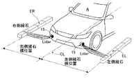
ライダー15とレーダー16は、自車の前端位置に、出力波の照射軸を車両前方に向けて配置され、反射波を受けることにより自車前方の物体の存在を検知すると共に、自車前方の物体までの距離を検知する。ライダー15とレーダー16という2種類の測距センサを組み合わせてライダー/レーダーが構成され、例えば、レーザーレーダー、ミリ波レーダー、超音波レーダー、レーザーレンジファインダーなどを用いることができる。このライダー15とレーダー16では、自車走行路上物体・自車走行路外物体(道路構造物、先行車、後続車、対向車、周囲車両、歩行者、自転車、二輪車)などの位置と物体までの距離を検知する。
The
ここで、ライダー15は、図3に示すように、自車Aの前端左右位置に右斜め下向きと左斜め下向きに首振り可能に設けられ、右側縁石横位置検出機能と左側縁石横位置検出機能とを有する。なお、右側縁石横位置とは、自車Aの車幅方向中心線CLの位置から右側縁石ERの内端位置までの長さをいう。左側縁石横位置とは、自車Aの車幅方向中心線CLの位置から左側縁石ELの内端位置までの長さをいう。なお、右側縁石ERと左側縁石ELは、左右の道路端であり、右側縁石横位置より所定距離内側位置と左側白線横位置より所定距離内側位置が、左右の車線境界検出結果とされる。
Here, as shown in FIG. 3, the
周囲環境認識ユニット2は、各認識カメラ11,12,13,14からの画像データとライダー/レーダー15,16から物体データとを入力する。この周囲環境認識ユニット2は、画像データと物体データのキャリブレーションデータを生成するキャリブレーション処理部21と、キャリブレーションデータに基づいて物体認識処理を行う物体認識処理部22と、を有する。
The surrounding environment recognition unit 2 inputs image data from the
キャリブレーション処理部21は、各認識カメラ11,12,13,14からの画像データのパラメータと、ライダー/レーダー15,16から物体データのパラメータとを推定し、パラメータを使用して画像データや物体データのキャリブレーションデータを生成して出力する。例えば、各認識カメラ11,12,13,14からの画像データの場合、パラメータを使用して光軸やレンズ歪みの補正などを行う。
The
物体認識処理部22は、キャリブレーション処理部21からのキャリブレーションデータを入力し、キャリブレーションデータに基づいて物体認識処理を行い、認識結果データを出力する。この物体認識処理部22では、例えば、画像データと物体データとを比較処理し、画像データによる物体候補の位置に物体データにより物体が存在することが確認されると、物体の存在を認識すると共に物体が何であるかを認識する。
The object
ナビゲーション制御ユニット3は、GNSSアンテナ31からの自車位置情報を入力し、道路情報を含む地図データと衛星通信を利用したGPS(全地球測位システム)を組み合わせ、ルート検索により現在位置から目的地までの目標経路を生成する。そして、生成した目標経路を地図上に表示すると共に、目標経路情報を出力する。
The navigation control unit 3 inputs the vehicle position information from the
ここで、「GNSS」は「Global Navigation Satellite System:全地球航法衛星システム」の略称であり、「GPS」は「Global Positioning System」の略称である。なお、ナビゲーション制御ユニット3の詳細構成については後述する。 Here, "GNSS" is an abbreviation for "Global Navigation Satellite System: Global Navigation Satellite System", and "GPS" is an abbreviation for "Global Positioning System". The detailed configuration of the navigation control unit 3 will be described later.
自動運転制御ユニット4は、周囲環境認識ユニット2の物体認識処理部22からの認識結果データと、ナビゲーション制御ユニット3からの目標経路情報を入力する。そして、入力情報に基づいて目標車速や目標加速度や目標減速度を生成する。さらに、生成された目標加速度により駆動制御指令値を演算し、演算結果を駆動アクチュエータ51へ出力する。生成された目標減速度により制動制御指令値を演算し、演算結果を制動アクチュエータ52へ出力する。入力された目標経路情報により舵角制御指令値を演算し、演算結果を舵角アクチュエータ53へ出力する。
The automatic driving control unit 4 inputs recognition result data from the object
アクチュエータ5は、駆動アクチュエータ51と、制動アクチュエータ52と、舵角アクチュエータ53と、を有する。
The
駆動アクチュエータ51は、自動運転制御ユニット4から駆動制御指令値を入力し、駆動源駆動力を制御するアクチュエータである。つまり、エンジン車の場合は、エンジンアクチュエータを用いる。ハイブリッド車の場合は、エンジンアクチュエータとモータアクチュエータを用いる。電気自動車の場合、モータアクチュエータを用いる。
The
制動アクチュエータ52は、自動運転制御ユニット4から制動制御指令値を入力し、ブレーキ制動力を制御するアクチュエータである。なお、制動アクチュエータ52としては、油圧ブースタや電動ブースタなどを用いる。
The
舵角アクチュエータ53は、自動運転制御ユニット4から舵角制御指令値を入力し、操舵輪の転舵角を制御するアクチュエータである。なお、舵角アクチュエータ53としては、舵角制御モータなどを用いる。
The
[ナビゲーション制御ユニットの詳細構成]
目的地を設定し、最適な目標経路を演算し、自動運転用の目標経路を表示するナビゲーション制御ユニット3の詳細構成を、図1に基づいて説明する。[Detailed configuration of navigation control unit]
A detailed configuration of the navigation control unit 3 that sets a destination, calculates an optimal target route, and displays a target route for automatic driving will be described with reference to FIG.
ナビゲーション制御ユニット3は、図1に示すように、GNSSアンテナ31,31と、位置情報処理部32と、目的地設定部33と、地図データ記憶部34と、ルート検索処理部35と、目標経路補正器36と、表示デバイス37と、を備えている。
As shown in FIG. 1, the navigation control unit 3 includes a
GNSSアンテナ31,31は、自車の前後位置に取り付けることで、自車の車両姿勢角である方角情報を、その位置関係にて取得する。なお、GNSSアンテナ31,31による受信状況が悪化した際は、車載のジャイロセンサからのセンサ情報に基づいてヨーレート情報を取得し、取得したヨーレート情報を成分することで方角情報を補間する。
The
位置情報処理部32は、GNSSアンテナ31,31から入力される衛星通信情報に基づいて、自車の停車位置や自車の走行位置の緯度・経度の検出処理を行う。位置情報処理部32からの自車位置情報は、ルート検索処理部35へ出力される。
The position
目的地設定部33は、ドライバによる表示デバイス37の表示画面へのタッチパネル操作などにより、自車の目的地の入力設定を行う。目的地設定部33からの目的地情報は、ルート検索処理部35へ出力される。
The
地図データ記憶部34は、緯度経度と地図情報が対応づけられた、いわゆる電子地図データの記憶部である。地図データには、各地点に対応づけられた道路情報を有し、道路情報は、ノードと、ノード間を接続するリンクにより定義される。道路情報は、道路の位置/領域により道路を特定する情報と、道路ごとの道路種別、道路ごとの道路幅、道路の形状情報とを含む。道路情報は、各道路リンクの識別情報ごとに、交差点の位置、交差点の進入方向、交差点の種別その他の交差点に関する情報を対応づけて記憶する。また、道路情報は、各道路リンクの識別情報ごとに、道路種別、道路幅、道路形状、直進の可否、進行の優先関係、追い越しの可否(隣接レーンへの進入の可否)、制限速度、その他の道路に関する情報を対応づけて記憶する。
The map
ルート検索処理部35は、位置情報処理部32からの自車位置情報と、目的地設定部33からの目的地情報と、地図データ記憶部34からの道路地図情報(道路地図データ)と、を入力する。そして、道路地図情報に基づいてルートコスト計算などによって目標経路を生成する。なお、目標経路の生成は、GPSと地図を用いて生成しても良いが、GPSと地図を用いる代わりに、先行車が存在するとき、先行車の走行軌跡を目標経路としても良い。この場合、GPSの位置精度が低いとき、走行軌跡を目標経路として用いることで、後述する目標経路補正器36での横並行移動量が小さくて済み、よりスムーズな車両挙動にすることができる。
The route
目標経路補正器36は、物体認識処理部22からの認識結果データと、ルート検索処理部35からの目標経路と、を入力する。目標経路以外に、白線横方向距離(左右)、静止物体横方向距離(左右)、縁石横方向距離(左右)、ドライバによる方向指示器(ウインカ)の使用状況、車線変更状況、車速などの情報を入力する。これらの入力情報に基づいて、自車が走行する車線の車線境界を検出する。そして、検出した車線境界と地図上における目標経路との位置関係を比較し、目標経路が車線境界に対して所定距離以内に存在する場合、或いは、目標経路が車線境界に対して自車とは反対側に存在する場合、目標経路を横方向の並行移動により補正する。
The
ここで、「所定距離」とは、自車が車線境界に近づいたとき、ドライバに対して不安感を与える距離をいい、例えば、自車の車幅方向中心線から車線境界までが2m程度(自車の側面から車線境界までが1m程度)の距離とする。なお、目標経路が車線境界に対して自車とは反対側に存在する場合には、自車との距離にかかわらず、目標経路を横方向の並行移動により補正する。 Here, the "predetermined distance" refers to a distance at which the driver feels anxious to the driver when the vehicle approaches the lane boundary. For example, the distance from the vehicle width direction center line to the lane boundary is about 2 m ( (The distance from the side of the vehicle to the lane boundary is about 1m.) When the target route is on the opposite side of the lane boundary from the own vehicle, the target route is corrected by parallel translation in the horizontal direction regardless of the distance from the own vehicle.
表示デバイス37は、地図データ記憶部34からの地図データ情報と、目標経路補正器36からの目標経路情報を入力する。そして、表示画面に、地図と道路と目標経路と自車位置と目的地を表示する。つまり、表示デバイス37は、自動運転による走行中、自車が地図上で何処を移動しているかなどの自車位置視覚情報を提供する。
The
[目標経路補正器の全体構成]
図4は、実施例1においてナビゲーション制御ユニット3(コントローラ)に有する目標経路補正器36を示す。以下、図4に基づいて目標経路補正器36の全体構成を説明する。[Overall configuration of target path compensator]
FIG. 4 shows a
目標経路補正器36は、自動運転による走行中、ナビゲーション情報を用いて検出した自車位置を地図情報に重ね合わせたとき、自車位置と目標経路との間で生じるナビゲーション誤差を、目標経路の横並行移動により補正する。この目標経路補正器36は、図4に示すように、道路境界情報統合部361(車線境界検出部)と、横補正量算出部362と、横並行移動部363と、を有する。
The
道路境界情報統合部361は、白線横方向距離(左右)、静止物体横方向距離(左右)、縁石横方向距離(左右)、ドライバによる方向指示器(ウインカ)の使用状況、車線変更状況、車速などの情報を入力する。そして、自車Aが走行する車線の車線境界を検出し、自車Aと車線境界横方向距離(左右)を、横補正量算出部362へ出力する。
The road boundary
横補正量算出部362は、ルート検索処理部35からの目標経路と、道路境界情報統合部361からの車線境界横方向距離(左右)と、ドライバによる方向指示器の使用状況、車線変更状況、車速、方角などの情報を入力する。そして、検出した車線境界と地図上における目標経路との位置関係を比較し、目標経路が車線境界に対して所定距離以内に存在する場合、或いは、目標経路が車線境界に対して自車Aとは反対側に存在する場合、目標経路の横補正量を算出する。
The lateral correction
横並行移動部363は、ルート検索処理部35からの目標経路と、横補正量算出部362からの横補正量と、を入力する。そして、横補正量が算出されると、図4の右下の枠Bに示すように、目標経路を横補正量だけ横方向の並行移動により補正し、新しい目標経路を生成する。この目標経路の横並行移動補正により、自車Aの進行方向と目標経路がずれているとき、自車Aの進行方向と新しい目標経路との一致性が高められる。
The horizontal
[横補正量算出部362の詳細構成]
図5は、目標経路補正器36のうち横補正量算出部362を示す。以下、図5に基づいて横補正量算出部362の詳細構成を説明する。[Detailed Configuration of Horizontal Correction Amount Calculation Unit 362]
FIG. 5 shows the lateral correction
横補正量算出部362は、図5に示すように、横偏差算出部362aと、位置関係理解部362bと、横補正量計算部362cと、変化レート最大値決定部362dと、レートリミッタ362eと、を有する。
As shown in FIG. 5, the horizontal correction
横偏差算出部362aは、ルート検索処理部35からの目標経路を入力し、目標経路と自車の横偏差Y0を算出する。
The lateral
位置関係理解部362bは、横偏差算出部362aからの横偏差Y0と、道路境界情報統合部361からの車線境界横方向距離(左右)を入力する。そして、目標経路と車線端との位置関係の比較により、目標経路と車線境界との位置関係を理解(把握)する。このとき、目標経路が車線境界(左)に対して所定距離以内に存在する場合、或いは、目標経路が車線境界(左)に対して自車とは反対側に存在する場合、左境界検出状況(フラグ)を出力する。一方、目標経路が車線境界(右)に対して所定距離以内に存在する場合、或いは、目標経路が車線境界(右)に対して自車とは反対側に存在する場合、右境界検出状況(フラグ)を出力する。
The positional
横補正量計算部362cは、位置関係理解部362bからの左境界検出状況(フラグ)及び右境界検出状況(フラグ)と、道路境界情報統合部361からの車線境界横方向距離(左右)を入力する。そして、目標経路の位置と自車の位置が一致するように、目標経路の横補正量を計算し、計算結果を横補正量目標値として出力する。
The lateral correction
変化レート最大値決定部362dは、ドライバによる方向指示器の使用状況と、車線変更状況と、車速と、左境界検出状況(フラグ)と、右境界検出状況(フラグ)とを入力する。そして、横補正量変化レート(目標経路の移動速度)の下限値と上限値を決定する。
つまり、変化レート最大値決定部362dは、目標経路を横方向の並行移動により補正する際、横方向に並行移動させる目標経路の移動速度(横補正量変化レート)を、所定速度に規定するだけではなく、状況に応じて可変に規定する機能を有する。The change rate maximum
That is, when correcting the target route by the parallel movement in the horizontal direction, the change rate maximum
レートリミッタ部362eは、変化レート最大値決定部362dからの横補正量目標値と、変化レート最大値決定部362dからの横補正量変化レート下限値及び横補正量変化レート上限値と、方角とを入力する。そして、横補正量目標値に対して横補正量変化レート(目標経路の横並行移動速度)により制限を加えて横補正量とする。
The
変化レート最大値決定部362dは、低車速時変化抑制部362d1と、第1レート切替部362d2と、第2レート切替部362d3と、第3レート切替部362d4と、第4レート切替部362d5と、第1レート積算部362d6と、第2レート積算部362d7と、を有する。
The maximum change
低車速時変化抑制部362d1は、車速を入力し、自車の車速が低下すると、車速低下に応じて目標経路の移動速度を小さくするように車速対応変化レートを決める。そして、自車が停車すると、車速対応変化レートをゼロにする。 The low vehicle speed change suppression unit 362d1 inputs the vehicle speed, and when the vehicle speed of the own vehicle decreases, determines the vehicle speed corresponding change rate so as to decrease the moving speed of the target route according to the decrease in vehicle speed. When the vehicle stops, the change rate corresponding to the vehicle speed is set to zero.
第1レート切替部362d2は、車線変更状況をトリガーとして、車線変更のない通常走行シーンのとき、車速対応変化レートを選択し、車線変更状況が入力されると、変化レートをゼロに切り替える。 The first rate switching unit 362d2 uses the lane change status as a trigger to select a vehicle speed-based change rate during a normal driving scene without a lane change, and switches the change rate to zero when the lane change status is input.
第2レート切替部362d3は、ドライバによる方向指示器使用状況をトリガーとし、方向指示器不使用のとき、第1レート切替部362d2からの変化レートに切り替え、方向指示器使用状況が入力されると変化レート=∞に切り替える。 The second rate switching unit 362d3 is triggered by the use of the direction indicator by the driver, switches to the change rate from the first rate switching unit 362d2 when the direction indicator is not used, and receives the direction indicator use status. Change rate = レ ー ト.
第3レート切替部362d4は、右境界検出状況(フラグ)をトリガーとし、レート大(固定値)とレート小(固定値)を切り替える。 The third rate switching unit 362d4 switches between a large rate (fixed value) and a small rate (fixed value) using the right boundary detection status (flag) as a trigger.
第4レート切替部362d5は、左境界検出状況(フラグ)をトリガーとし、レート大(固定値)とレート小(固定値)を切り替える。 The fourth rate switching unit 362d5 switches between a large rate (fixed value) and a small rate (fixed value) using the left boundary detection status (flag) as a trigger.
第1レート積算部362d6は、第2レート切替部362d3からの変化レートと、第3レート切替部362d4からの変化レートを入力し、両変化レートの積算により横補正量変化レート上限値を算出する。 The first rate integrating unit 362d6 receives the change rate from the second rate switching unit 362d3 and the change rate from the third rate switching unit 362d4, and calculates the lateral correction amount change rate upper limit value by integrating the two change rates. .
第2レート積算部362d7は、第2レート切替部362d3からの変化レートと、第4レート切替部362d5からの変化レートを入力し、両変化レートの積算により横補正量変化レート上限値を算出する。 The second rate integrating unit 362d7 receives the change rate from the second rate switching unit 362d3 and the change rate from the fourth rate switching unit 362d5, and calculates the lateral correction amount change rate upper limit value by integrating the two change rates. .
この変化レート最大値決定部362dでは、下記に列挙するように、目標経路を横並行移動による補正するときの移動速度(変化レート)を制御する。
The change rate maximum
(a) 目標経路を横方向に並行移動させるとき、自車が車線変更すると、車線変更中、目標経路の移動速度をゼロとし、並行移動量を保持する(第1レート切替部362d2)。 (a) When the target route is moved in parallel in the horizontal direction, if the vehicle changes lanes, the moving speed of the target route is set to zero and the amount of parallel movement is maintained during the lane change (first rate switching unit 362d2).
(b) 目標経路を横方向に並行移動させるとき、自車の車速が低下すると、車速低下に応じて目標経路の移動速度を小さくする(低車速時変化抑制部362d1)。 (b) When the target route is moved in parallel in the horizontal direction, if the vehicle speed of the own vehicle decreases, the moving speed of the target route is reduced according to the decrease in the vehicle speed (low-speed change control unit 362d1).
(c) 目標経路を横方向に並行移動させるとき、自車が停車すると、目標経路の移動速度をゼロとし、並行移動量を保持する(低車速時変化抑制部362d1)。 (c) When moving the target route in parallel in the horizontal direction, when the own vehicle stops, the moving speed of the target route is set to zero, and the amount of parallel movement is maintained (the low vehicle speed change suppression unit 362d1).
(d) 目標経路を横方向に並行移動させるとき、自車の近くに左右車線端を検出しないと、左右への目標経路の移動速度を遅くする(第3,第4レート切替部362d4,362d5)。 (d) When moving the target route in the horizontal direction, if the left and right lane edges are not detected near the own vehicle, the moving speed of the target route to the left and right is reduced (third and fourth rate switching units 362d4 and 362d5). ).
(e) 目標経路を横方向に並行移動させるとき、左側のみ自車の近くに車線端を検出すると、左への目標経路の移動速度を遅くし、右への目標経路の移動速度を速くする(第3,第4レート切替部362d4,362d5)。 (e) When moving the target route in parallel in the horizontal direction, if the lane edge is detected near the vehicle only on the left side, the moving speed of the target route to the left is reduced and the moving speed of the target route to the right is increased. (Third and fourth rate switching units 362d4 and 362d5).
(f) 目標経路を横方向に並行移動させるとき、右側のみ自車の近くに車線端を検出すると、左への目標経路の移動速度を速くし、右への目標経路の移動速度を遅くする(第3,第4レート切替部362d4,362d5)。 (f) When moving the target route in parallel in the horizontal direction, if the lane edge is detected near the vehicle only on the right side, the moving speed of the target route to the left is increased, and the moving speed of the target route to the right is reduced. (Third and fourth rate switching units 362d4 and 362d5).
(g) 目標経路を横方向に並行移動させるとき、自車の近くに左右車線端を検出すると、左右への目標経路の移動速度を速くする(第3,第4レート切替部362d4,362d5)。 (g) When moving the target route in parallel in the horizontal direction, if the left and right lane edges are detected near the own vehicle, the moving speed of the target route to the left and right is increased (third and fourth rate switching units 362d4 and 362d5). .
[レートリミッタ部の詳細構成]
図6は、図5に示す横補正量算出部362のうちレートリミッタ部362eを示し、図7は、レートリミッタ部362eを説明するのに必要な地図座標系と車両座標系と方角などを示す。以下、図6及び図7に基づいて、レートリミッタ部362eの詳細構成を説明する。[Detailed configuration of rate limiter section]
FIG. 6 shows the
レートリミッタ部362eは、図6に示すように、レートリミッタ362e1と、回転変換部362e2と、X方向補正量読み出し部362e3と、Y方向補正量読み出し部362e4と、回転逆変換部362e5と、縦補正量減少部362e6と、を有する。
As shown in FIG. 6, the
レートリミッタ362e1は、横補正量変化レート上限値と、横補正量変化レート下限値と、AVM等で算出した横補正量目標値と、回転逆変換部362e5からの方角による横補正量と、を入力する。そして、横補正量目標値を、変化レート上限値と変化レート下限値と方角による横補正量とによって制限することで、最終的な横補正量を出力する。 The rate limiter 362e1 calculates the lateral correction amount change rate upper limit value, the lateral correction amount change rate lower limit value, the lateral correction amount target value calculated by the AVM or the like, and the lateral correction amount based on the direction from the rotation inverse converter 362e5. input. Then, the final lateral correction amount is output by limiting the lateral correction amount target value with the upper limit value of the change rate, the lower limit value of the change rate, and the lateral correction amount based on the direction.
回転変換部362e2は、方角と、レートリミッタ362e1からの横補正量と、縦補正量減少部362e6からの縦補正量(横補正量の縦方向成分)と、を入力する。そして、レートリミッタ362e1からの車両座標系による横補正量を、図7に示すように、方角を用いて地図座標系に回転変換し、地図座標系でのX方向補正量(横補正量の経度方向成分)とY方向補正量(横補正量の緯度方向成分)を出力する。 The rotation conversion unit 362e2 inputs the direction, the horizontal correction amount from the rate limiter 362e1, and the vertical correction amount (vertical component of the horizontal correction amount) from the vertical correction amount reduction unit 362e6. Then, the horizontal correction amount in the vehicle coordinate system from the rate limiter 362e1 is rotationally converted to the map coordinate system using the direction as shown in FIG. 7, and the X-direction correction amount (the longitude of the horizontal correction amount) in the map coordinate system is used. Direction component) and the Y-direction correction amount (latitude component of the lateral correction amount) are output.
X方向補正量読み出し部362e3は、回転変換部362e2から地図座標系でのX方向補正量(横補正量の経度方向成分)を入力する。そして、1ステップ前のX方向補正量(横補正量の経度方向成分)を読み出す。 The X direction correction amount reading unit 362e3 inputs the X direction correction amount (longitudinal component of the horizontal correction amount) in the map coordinate system from the rotation conversion unit 362e2. Then, the X-direction correction amount (longitudinal component of the horizontal correction amount) one step before is read.
Y方向補正量読み出し部362e4は、回転変換部362e2から地図座標系でのY方向補正量(横補正量の緯度方向成分)を入力する。そして、1ステップ前のY方向補正量(横補正量の緯度方向成分)を読み出す。 The Y-direction correction amount reading unit 362e4 inputs the Y-direction correction amount (latitude component of the lateral correction amount) in the map coordinate system from the rotation conversion unit 362e2. Then, the Y-direction correction amount (the latitude-direction component of the horizontal correction amount) one step before is read.
回転逆変換部362e5は、方角と、1ステップ前のX方向補正量(横補正量の経度方向成分)と、1ステップ前のY方向補正量(横補正量の緯度方向成分)と、を入力する。そして、地図座標系による横補正量を、方角を用いて車両座標系に回転逆変換し、車両座標系での横補正量(車両座標系での横方向成分)と縦補正量(車両座標系での縦方向成分)を出力する。 The rotation reverse conversion unit 362e5 inputs the direction, the X-direction correction amount one step before (the longitude direction component of the horizontal correction amount), and the Y-direction correction amount one step before (the latitude direction component of the horizontal correction amount). I do. Then, the horizontal correction amount in the map coordinate system is inversely rotated and converted into the vehicle coordinate system using the direction, and the horizontal correction amount (horizontal component in the vehicle coordinate system) and the vertical correction amount (vehicle coordinate system) in the vehicle coordinate system. Is output in the vertical direction.
縦補正量減少部362e6は、回転逆変換部362e5から縦補正量(車両座標系での縦方向成分)を入力し、1未満の減少係数により徐々に減少させた縦補正量を回転変換部362e2に出力する。 The vertical correction amount reduction unit 362e6 receives the vertical correction amount (vertical component in the vehicle coordinate system) from the rotation inverse conversion unit 362e5, and converts the vertical correction amount gradually reduced by a reduction coefficient of less than 1 into the rotation conversion unit 362e2. Output to
次に、作用を説明する。
実施例1の作用を、「比較例での位置誤差補正作用」、「実施例1での位置誤差補正作用」に分けて説明する。Next, the operation will be described.
The operation of the first embodiment will be described by dividing into “position error correction operation in the comparative example” and “position error correction operation in the first embodiment”.
[比較例での位置誤差補正作用]
図8は、白線を有さない交差点で生成される目標経路TL1(補正前)・目標経路TL2(補正後、車両姿勢無視)の比較を示す。図9は、白線を有さない交差点での目標経路TL2(補正後、車両姿勢無視)と目標経路TL3(補正後、車両姿勢考慮)とで比較した横補正量変化特性を示す。以下、図8及び図9に基づいて比較例での位置誤差補正作用を説明する。[Position error correction action in comparative example]
FIG. 8 shows a comparison between a target route TL1 (before correction) and a target route TL2 (after correction, ignoring the vehicle attitude) generated at an intersection having no white line. FIG. 9 shows a lateral correction amount change characteristic of a target route TL2 (after correction, ignoring the vehicle attitude) at an intersection having no white line and a target route TL3 (after correction, considering the vehicle attitude). Hereinafter, the position error correction operation in the comparative example will be described with reference to FIGS.
まず、比較例は、補正前の目標経路TL1に対し、横移動補正を行うが方角を入力情報に含まず車両姿勢を無視したものとする。 First, in the comparative example, it is assumed that lateral movement correction is performed on the target route TL1 before correction, but the direction is not included in the input information and the vehicle attitude is ignored.
GPS位置ずれは、短時間に限れば地図座標系で見た際にどちらかの方角に一定値だけずれている。しかし、これを補正しようとする場合、自車の進行方向の法線成分は各種センサより補正可能であるが、進行方向は情報が乏しいため難しい。
これに対し、比較例のように、法線方向成分のみを取扱い(横補正量と呼ぶ)、道路境界情報より更新を行うことも考えられる。しかし、交差点で右左折を行う際、交差点内では通常白線が無いため、道路境界が得られず、進行方向も変わってしまうため、正しい補正が行われない。For a short time, the GPS position shift is shifted by a certain value in either direction when viewed in the map coordinate system. However, when trying to correct this, the normal component of the traveling direction of the vehicle can be corrected by various sensors, but the traveling direction is difficult due to lack of information.
On the other hand, as in the comparative example, it is also conceivable to handle only the normal direction component (referred to as a lateral correction amount) and update the road boundary information. However, when making a right or left turn at an intersection, there is usually no white line inside the intersection, so that a road boundary cannot be obtained and the traveling direction changes, so that correct correction is not performed.
即ち、横移動補正を行うが方角を入力情報に含まず車両姿勢を無視した比較例の場合、図8に示すように、補正前の目標経路TL1に対し、補正後の目標経路TL2(補正後、車両姿勢無視)は、曲率変化部が大きくカーブ外側に膨らんだものになる。そして、交差点を抜けたときに自車Aの位置が左右白線のセンターラインから外れたものになる。 That is, in the comparative example in which the lateral movement correction is performed but the direction is not included in the input information and the vehicle attitude is ignored, as shown in FIG. 8, the corrected target path TL2 (the corrected target path TL2) In other words, the vehicle attitude is ignored), the curvature change portion is greatly expanded to the outside of the curve. Then, when passing through the intersection, the position of the own vehicle A deviates from the center line of the left and right white lines.
このため、白線を有さない交差点では、図9の目標経路TL2(補正後、車両姿勢無視)の横補正量変化特性に示すように、時刻t1から方角が左折側に変化を開始したとき、交差点を抜けて直進走行に入るまでに時刻t1から時刻t3までの所要時間ΔT2を要する。 For this reason, at an intersection having no white line, as shown in the lateral correction amount change characteristic of the target route TL2 (after correction, ignoring the vehicle attitude) in FIG. It takes a required time ΔT2 from time t1 to time t3 before going straight through the intersection.
[実施例1での位置誤差補正作用]
図8は、白線を有さない交差点で生成される目標経路TL1(補正前)・目標経路TL2(補正後、車両姿勢無視)・目標経路TL3(補正後、車両姿勢考慮)の比較を示す。図9は、白線を有さない交差点での目標経路TL2(補正後、車両姿勢無視)と目標経路TL3(補正後、車両姿勢考慮)とで比較した横補正量変化特性と目標経路TL3(補正後、車両姿勢考慮)による車両姿勢角(方角)の変化特性を示す。以下、図6、図8及び図9に基づいて実施例1での位置誤差補正作用を説明する。[Position Error Correction Function in First Embodiment]
FIG. 8 shows a comparison of a target route TL1 (before correction), a target route TL2 (after correction, ignoring the vehicle attitude), and a target route TL3 (after correction, considering the vehicle attitude) generated at an intersection having no white line. FIG. 9 shows a lateral correction amount change characteristic and a target route TL3 (correction) obtained by comparing the target route TL2 (after correction, ignoring the vehicle attitude) and the target route TL3 (after correction, considering the vehicle attitude) at an intersection having no white line. Later, the change characteristic of the vehicle attitude angle (direction) depending on the vehicle attitude is shown. Hereinafter, the position error correction operation in the first embodiment will be described with reference to FIGS. 6, 8, and 9.
まず、レートリミッタ部362eにおける方角による横補正量の算出作用を説明する。レートリミッタ362e1において、横補正量変化レート上限値と、横補正量変化レート下限値と、AVM等で算出した横補正量目標値と、回転逆変換部362e5からの方角による横補正量と、が入力される。そして、横補正量目標値を、変化レート上限値と変化レート下限値と方角による横補正量とによって制限することで、最終的な横補正量が出力される。このとき、回転逆変換部362e5からの方角による横補正量は、下記の処理により得られる。
First, the operation of calculating the lateral correction amount based on the direction in the
回転変換部362e2において、方角と、レートリミッタ362e1からの横補正量と、縦補正量減少部362e6からの縦補正量(横補正量の縦方向成分)と、が入力される。そして、レートリミッタ362e1からの車両座標系による横補正量が、方角を用いて地図座標系に回転変換され、地図座標系でのX方向補正量(横補正量の経度方向成分)とY方向補正量(横補正量の緯度方向成分)が出力される。 In the rotation conversion unit 362e2, the direction, the horizontal correction amount from the rate limiter 362e1, and the vertical correction amount (vertical component of the horizontal correction amount) from the vertical correction amount reduction unit 362e6 are input. Then, the lateral correction amount in the vehicle coordinate system from the rate limiter 362e1 is rotationally transformed into the map coordinate system using the direction, and the X-direction correction amount (longitudinal component of the lateral correction amount) and the Y-direction correction in the map coordinate system are used. The amount (the latitude component of the lateral correction amount) is output.
X方向補正量読み出し部362e3において、回転変換部362e2から地図座標系でのX方向補正量(横補正量の経度方向成分)が入力され、1ステップ前のX方向補正量(横補正量の経度方向成分)が読み出される。Y方向補正量読み出し部362e4において、回転変換部362e2から地図座標系でのY方向補正量(横補正量の緯度方向成分)が入力され、1ステップ前のY方向補正量(横補正量の緯度方向成分)が読み出される。 In the X-direction correction amount reading unit 362e3, the X-direction correction amount (longitudinal component of the horizontal correction amount) in the map coordinate system is input from the rotation conversion unit 362e2, and the X-direction correction amount one step before (the longitude of the horizontal correction amount) Direction component) is read. In the Y-direction correction amount reading unit 362e4, the Y-direction correction amount (latitude component of the horizontal correction amount) in the map coordinate system is input from the rotation conversion unit 362e2, and the Y-direction correction amount one step before (latitude of the horizontal correction amount) Direction component) is read.
そして、回転逆変換部362e5において、方角と、1ステップ前のX方向補正量(横補正量の経度方向成分)と、1ステップ前のY方向補正量(横補正量の緯度方向成分)と、が入力される。そして、地図座標系による横補正量が、方角を用いて車両座標系に回転逆変換され、車両座標系での横補正量(車両座標系での横方向成分)と縦補正量(車両座標系での縦方向成分)が出力される。このとき、縦補正量減少部362e6において、回転逆変換部362e5から縦補正量(車両座標系での縦方向成分)が入力され、1未満の減少係数により徐々に減少させた縦補正量が回転変換部362e2に出力される。 Then, in the rotation inverse transform unit 362e5, the direction, the X-direction correction amount one step before (the longitude component of the lateral correction amount), and the Y-direction correction amount one step before (the latitude component of the lateral correction amount) Is entered. Then, the lateral correction amount in the map coordinate system is rotationally inversely transformed into the vehicle coordinate system using the direction, and the lateral correction amount in the vehicle coordinate system (lateral component in the vehicle coordinate system) and the vertical correction amount (vehicle coordinate system) Is output in the vertical direction. At this time, in the vertical correction amount reducing unit 362e6, the vertical correction amount (vertical component in the vehicle coordinate system) is input from the rotation inverse conversion unit 362e5, and the vertical correction amount gradually reduced by a reduction coefficient less than 1 is rotated. Output to conversion section 362e2.
このように、実施例1は、横補正量を、地図座標系でみた経度方向成分と緯度方向成分の両方により取り扱うものである。そして、目標経路の横移動速度を自車の方角によって変化させるとき、車両座標系による横補正量を方角により地図座標系に回転変換を行い、このとき、車両座標系の進行方向の法線方向成分である横方向成分のみを更新し、進行方向成分である縦方向成分は不変としている。その後、地図座標系を車両座標系に戻す逆回転変換を行う。さらに詳しくは、目標経路の横移動速度を自車の方角によって変化させるとき、ある制御ステップにおける横補正量が地図座標系であるX,Y座標系で記憶される。次のステップでX方向成分とY方向成分が読み出され、そのステップにおける車両姿勢角(方角)分だけ逆回転変換することで車両座標系における縦横成分に変換される。そして、新しく車線境界検出結果を用いて得られた横補正量目標値と比較され、そのステップにおける最終的な横補正量が算出される。そして、再度、車両姿勢角(方角)分だけ回転変換してX,Y座標系での横補正量が算出される。この処理が繰り返される。 As described above, in the first embodiment, the lateral correction amount is handled by both the longitude component and the latitude component in the map coordinate system. Then, when changing the lateral movement speed of the target route according to the direction of the own vehicle, the lateral correction amount in the vehicle coordinate system is rotationally converted to the map coordinate system in the direction, and at this time, the normal direction of the traveling direction of the vehicle coordinate system Only the horizontal component as the component is updated, and the vertical component as the traveling direction component is unchanged. Then, reverse rotation transformation is performed to return the map coordinate system to the vehicle coordinate system. More specifically, when the lateral movement speed of the target route is changed depending on the direction of the own vehicle, the lateral correction amount in a certain control step is stored in the X, Y coordinate system that is the map coordinate system. In the next step, the X-direction component and the Y-direction component are read, and are converted into the vertical and horizontal components in the vehicle coordinate system by performing reverse rotation conversion by the vehicle attitude angle (direction) in that step. Then, it is compared with a lateral correction amount target value newly obtained using the lane boundary detection result, and the final lateral correction amount in that step is calculated. Then, the rotation correction is performed again by the vehicle attitude angle (direction) to calculate the lateral correction amount in the X, Y coordinate system. This process is repeated.
したがって、横移動補正を行うが方角を入力情報に含み、車両姿勢を考慮した実施例1の場合、図8に示すように、補正前の目標経路TL1に対し、補正後の目標経路TL3(補正後、車両姿勢考慮)は、曲率変化部がカーブ外側に膨らむのが抑えられる。そして、交差点を抜けたときに自車Aの位置が左右白線のセンターラインのほぼ一致する。 Therefore, in the first embodiment in which the lateral movement correction is performed but the direction is included in the input information and the vehicle attitude is taken into consideration, as shown in FIG. 8, the corrected target path TL3 (corrected Later, considering the vehicle attitude), the curvature changing portion is suppressed from expanding to the outside of the curve. Then, when passing through the intersection, the position of the vehicle A substantially coincides with the center line of the left and right white lines.
このため、白線を有さない交差点では、図9の目標経路TL3(補正後、車両姿勢考慮)において矢印Cで囲まれた横補正量変化特性に示すように、横補正量の低下勾配が大きくなり、横並行移動速度が高くなる。この結果、時刻t1から方角が左折側に変化を開始したとき、交差点を抜けて直進走行に入るまでに時刻t1から時刻t2までの所要時間ΔT1(<ΔT2)に短縮される。 For this reason, at the intersection having no white line, the decrease gradient of the lateral correction amount is large as indicated by the lateral correction amount change characteristic surrounded by the arrow C in the target route TL3 (after the correction, the vehicle posture is considered) in FIG. And the horizontal parallel movement speed increases. As a result, when the direction starts to change to the left from time t1, the time required from time t1 to time t2, ΔT1 (<ΔT2), between the time t1 and time t2 before the vehicle goes straight ahead through the intersection.
次に、効果を説明する。
実施例1における自動運転車両の位置誤差補正方法及び位置誤差補正装置にあっては、下記に列挙する効果が得られる。Next, effects will be described.
In the position error correction method and the position error correction device for the self-driving vehicle according to the first embodiment, the following effects can be obtained.
(1) 運転支援走行中(自動運転走行中)、自車位置と目標経路との間で生じる誤差を補正するコントローラ(ナビゲーション制御ユニット3)を備える。
この運転支援車両(自動運転車両)の位置誤差補正方法において、自車が走行する車線の車線境界を検出する。
検出した車線境界と地図上における目標経路との位置関係を比較することで目標経路の横補正量目標値を算出する。
横補正量目標値を得る目標経路の横移動速度を、自車の車両姿勢角である方角によって変化させることで横補正量を算出する。
目標経路を、横補正量の分だけ横方向に並行移動させることにより補正する(図8)。
このため、白線や横断歩道がない交差点であっても、交差点を右左折により通過した後の自車位置を車線内中央に近づける運転支援車両(自動運転車両)の位置誤差補正方法を提供することができる。(1) A controller (navigation control unit 3) that corrects an error generated between the position of the vehicle and the target route during driving assistance traveling (during automatic driving traveling).
In this method of correcting a position error of a driving support vehicle (autonomous driving vehicle), a lane boundary of a lane in which the own vehicle runs is detected.
A lateral correction amount target value of the target route is calculated by comparing the positional relationship between the detected lane boundary and the target route on the map.
The lateral correction amount is calculated by changing the lateral movement speed of the target route for obtaining the lateral correction amount target value according to the direction which is the vehicle attitude angle of the own vehicle.
The target path is corrected by moving the target path in the horizontal direction by the horizontal correction amount (FIG. 8).
For this reason, even if it is an intersection without a white line or a pedestrian crossing, a position error correction method for a driving support vehicle (autonomous driving vehicle) that brings the position of the own vehicle closer to the center of the lane after passing through the intersection by turning left or right is provided. Can be.
(2) 横補正量を、地図座標系でみた経度方向成分と緯度方向成分の両方により取り扱うものである。
目標経路の横移動速度を自車の方角によって変化させるとき、車両座標系による横補正量を方角により地図座標系に回転変換を行い、このとき、車両座標系の進行方向の法線方向成分である横方向成分のみを更新し、進行方向成分である縦方向成分は不変とする。
その後、地図座標系を車両座標系に戻す逆回転変換を行う(図6)。
このため、(1)の効果に加え、地図座標系上にて横補正量を値だけでなく方向をもったベクトル値として扱うことで、交差点以外のS字カーブ路走行など、より複雑な姿勢変化に対しても対処することができる。(2) The horizontal correction amount is handled by both the longitude direction component and the latitude direction component in the map coordinate system.
When the lateral movement speed of the target route is changed according to the direction of the own vehicle, the lateral correction amount in the vehicle coordinate system is rotationally converted to the map coordinate system by the direction, and at this time, the normal direction component of the traveling direction of the vehicle coordinate system is used. Only a certain horizontal component is updated, and a vertical component which is a traveling component is unchanged.
Then, reverse rotation transformation is performed to return the map coordinate system to the vehicle coordinate system (FIG. 6).
For this reason, in addition to the effect of (1), by treating the horizontal correction amount as a vector value having a direction as well as a value on the map coordinate system, a more complicated posture such as running on an S-curve road other than an intersection can be obtained. We can cope with change.
(3) 目標経路の横移動速度を自車の方角によって変化させるとき、ある制御ステップにおける横補正量を地図座標系であるX,Y座標系で記憶し、次のステップでX方向成分とY方向成分を読み出し、そのステップにおける車両姿勢角(方角)分だけ逆回転変換して車両座標系における縦横成分に変換し、新しく車線境界検出結果を用いて得られた横補正量目標値と比較し、そのステップにおける最終的な横補正量を算出し、再度、車両姿勢角(方角)分だけ回転変換してX,Y座標系での横補正量を算出する(図6)。
このため、(2)の効果に加え、時間の経過と共に方角が変化するカーブ路での走行において繰り返し算出処理が実行されることにより、カーブ路で応答性の良い車両姿勢角の変化を達成することができる。(3) When changing the lateral movement speed of the target route according to the direction of the own vehicle, the lateral correction amount in a certain control step is stored in the X, Y coordinate system which is the map coordinate system, and the X direction component and Y are stored in the next step. The direction component is read out, reversely rotated by the vehicle attitude angle (direction) in that step, converted into the vertical and horizontal components in the vehicle coordinate system, and compared with the target lateral correction amount obtained using the newly detected lane boundary. Then, the final lateral correction amount in that step is calculated, and the rotation is again converted by the vehicle attitude angle (direction) to calculate the lateral correction amount in the X, Y coordinate system (FIG. 6).
For this reason, in addition to the effect of (2), a change in the vehicle attitude angle with good responsiveness is achieved on the curved road by repeatedly executing the calculation process when traveling on a curved road whose direction changes over time. be able to.
(4) 縦方向成分は、時間の経過にしたがって徐々に減少させる(図6)。
このため、(2)又は(3)の効果に加え、原則として保持している横補正量の縦方向成分を減少させていくことで、時間の経過と共に目標経路情報の縦方向のズレ量が拡大するのを抑えることができる。即ち、縦方向は車線境界(白線)の情報だけでは補正が難しく、かつ、長い時間経過してしまった場合、目標経路の縦方向ズレ量に変化があらわれる。(4) The longitudinal component is gradually reduced with time (FIG. 6).
For this reason, in addition to the effect of (2) or (3), by reducing the vertical component of the held horizontal correction amount in principle, the vertical deviation amount of the target route information can be reduced over time. Expansion can be suppressed. That is, in the vertical direction, it is difficult to correct only the information of the lane boundary (white line), and if a long time has elapsed, a change occurs in the vertical shift amount of the target route.
(5) 自車の車両姿勢角である方角情報は、2台のGNSSアンテナ31,31を自車に取り付けることで、その位置関係にて取得する。
GNSSアンテナ31,31による受信状況が悪化した際は、車載のジャイロセンサからのセンサ情報に基づいてヨーレート情報を取得し、取得したヨーレート情報を成分することで方角情報を補間する(図1)。
このため、(1)〜(4)の効果に加え、GPS受信状況が悪化した際にも、方角を用いた横並行移動による補正を継続することができる。(5) The direction information, which is the vehicle attitude angle of the own vehicle, is acquired by mounting two
When the reception status by the
For this reason, in addition to the effects of (1) to (4), even when the GPS reception condition deteriorates, the correction by the horizontal parallel movement using the direction can be continued.
(6) 運転支援走行中(自動運転走行中)、自車位置と目標経路との間で生じる誤差を補正するコントローラ(ナビゲーション制御ユニット3)を備える。
この運転支援車両(自動運転車両)の位置誤差補正装置において、コントローラ(ナビゲーション制御ユニット3)は、目標経路を補正する目標経路補正器36を有する。さらに、目標経路補正器36は、車線境界検出部(道路境界情報統合部361)と、横補正量算出部362と、横並行移動部363と、を有する。
車線境界検出部(道路境界情報統合部361)は、自車が走行する車線の車線境界を検出する。
横補正量算出部362は、車線境界の検出結果と地図上における目標経路との位置関係を比較することで目標経路の横補正量目標値を算出し、横補正量目標値を得る目標経路の横移動速度を、自車の車両姿勢角である方角によって変化させることで横補正量を算出する。
横並行移動部363は、横補正量が算出されると、目標経路を横補正量の分だけ横方向に並行移動させることにより補正する(図4)。
このため、白線や横断歩道がない交差点であっても、交差点を右左折により通過した後の自車位置を車線内中央に近づける運転支援車両(自動運転車両)の位置誤差補正装置を提供することができる。(6) A controller (navigation control unit 3) that corrects an error generated between the position of the vehicle and the target route during driving assistance driving (during automatic driving driving).
In this position error correction device for a driving support vehicle (autonomous driving vehicle), the controller (navigation control unit 3) has a
The lane boundary detection unit (road boundary information integration unit 361) detects the lane boundary of the lane in which the vehicle travels.
The lateral correction
When the horizontal correction amount is calculated, the horizontal
For this reason, even if it is an intersection without a white line or a pedestrian crossing, a position error correction device for a driving assistance vehicle (autonomous driving vehicle) that brings the position of the own vehicle closer to the center of the lane after passing through the intersection by turning right or left is provided. Can be.
以上、本開示の運転支援車両の位置誤差補正方法及び位置誤差補正装置を実施例1に基づき説明してきた。しかし、具体的な構成については、この実施例1に限られるものではなく、請求の範囲の各請求項に係る発明の要旨を逸脱しない限り、設計の変更や追加等は許容される。 As described above, the position error correction method and the position error correction device of the driving support vehicle according to the present disclosure have been described based on the first embodiment. However, the specific configuration is not limited to the first embodiment, and changes and additions of the design are allowed without departing from the gist of the invention according to each claim of the claims.
実施例1では、横補正量を算出し、横並行移動による目標経路の補正のみを行う例を示した。しかし、目標経路の横補正だけでなく、方角を用いることで横補正量の縦方向成分が取得されると、目標経路を、縦方向成分だけ縦方向に並行移動させて補正する縦補正を加えても良い。この縦補正を加えると、停止線までの距離等を地図情報からより正確に算出できるようになり、よりスムーズな停車ができるようになる。 In the first embodiment, an example has been described in which the lateral correction amount is calculated and only the correction of the target path by the lateral parallel movement is performed. However, when the vertical component of the horizontal correction amount is obtained by using the direction in addition to the horizontal correction of the target route, a vertical correction for correcting the target route by moving the target route in the vertical direction by the vertical component is added. May be. By adding this vertical correction, the distance to the stop line and the like can be calculated more accurately from the map information, and the vehicle can be stopped more smoothly.
実施例1では、自車の現在位置から目的地までの目標経路を生成するコントローラとして、ナビゲーション制御ユニット3を用いる例を示した。しかし、自車の現在位置から目的地までの目標経路を生成するコントローラとしては、自動運転制御ユニットとする例としても良い。さらに、目標経路生成機能を2つに分け、一部をナビゲーション制御ユニットで分担し、残りを自動運転制御ユニットで分担する例としても良い。 In the first embodiment, an example is described in which the navigation control unit 3 is used as a controller that generates a target route from the current position of the vehicle to the destination. However, the controller that generates the target route from the current position of the vehicle to the destination may be an example of an automatic driving control unit. Furthermore, the target route generation function may be divided into two parts, and a part may be shared by the navigation control unit, and the rest may be shared by the automatic operation control unit.
実施例1では、本開示の位置誤差補正方法及び位置誤差補正装置を自動運転モードの選択により操舵/駆動/制動が自動制御される自動運転車両に適用する例を示した。しかし、本開示の位置誤差補正方法及び位置誤差補正装置は、ドライバによる操舵運転/駆動運転/制動運転のうち、一部の運転を支援する運転支援車両であっても良い。要するに、ナビゲーションシステムによる位置誤差を補正することでドライバの運転支援をする車両であれば適用することができる。 In the first embodiment, an example is described in which the position error correction method and the position error correction device according to the present disclosure are applied to an automatic driving vehicle in which steering, driving, and braking are automatically controlled by selecting an automatic driving mode. However, the position error correction method and the position error correction device according to the present disclosure may be a driving support vehicle that supports a part of driving, driving, and braking by the driver. In short, the present invention can be applied to any vehicle that assists the driver in driving by correcting a position error caused by the navigation system.
Claims (6)
自車が走行する車線の車線境界を検出し、
前記車線境界の検出結果と地図上における前記目標経路との位置関係を比較することで前記目標経路の横補正量目標値を算出し、
前記横補正量目標値を得る前記目標経路の横移動速度を、自車の車両姿勢角である方角によって変化させることで横補正量を算出し、
前記目標経路を、前記横補正量の分だけ横方向に並行移動させることにより補正する
ことを特徴とする運転支援車両の位置誤差補正方法。During driving assistance traveling, a position error correction method for a driving assistance vehicle including a controller that corrects an error generated between the own vehicle position and a target route,
Detects the lane boundary of the lane on which the vehicle runs,
Calculating a lateral correction amount target value of the target route by comparing the positional relationship between the detection result of the lane boundary and the target route on the map,
The lateral correction amount is calculated by changing the lateral movement speed of the target route that obtains the lateral correction amount target value according to the direction that is the vehicle attitude angle of the own vehicle,
A method for correcting a position error of a driving support vehicle, wherein the target route is corrected by moving the target route in a lateral direction in parallel by the lateral correction amount.
前記横補正量を、地図座標系でみた経度方向成分と緯度方向成分の両方により取り扱うものであり、
前記目標経路の横移動速度を自車の方角によって変化させるとき、車両座標系による横補正量を方角により地図座標系に回転変換を行い、このとき、車両座標系の進行方向の法線方向成分である横方向成分のみを更新し、進行方向成分である縦方向成分は不変とし、
その後、地図座標系を車両座標系に戻す逆回転変換を行う
ことを特徴とする運転支援車両の位置誤差補正方法。The position error correction method for a driving assistance vehicle according to claim 1,
The horizontal correction amount is handled by both the longitude direction component and the latitude direction component as viewed in the map coordinate system,
When changing the lateral movement speed of the target route according to the direction of the own vehicle, the lateral correction amount in the vehicle coordinate system is rotationally converted to the map coordinate system by the direction, and at this time, the normal direction component of the traveling direction of the vehicle coordinate system Is updated, and the vertical component, which is the traveling direction component, is not changed.
Thereafter, a method of correcting a position error of the driving support vehicle, which performs a reverse rotation transformation to return the map coordinate system to the vehicle coordinate system.
前記目標経路の横移動速度を自車の方角によって変化させるとき、ある制御ステップにおける横補正量を地図座標系であるX,Y座標系で記憶し、次のステップでX方向成分とY方向成分を読み出し、そのステップにおける車両姿勢角(方角)分だけ逆回転変換して車両座標系における縦横成分に変換し、新しく車線境界検出結果を用いて得られた横補正量目標値と比較し、そのステップにおける最終的な横補正量を算出し、再度、車両姿勢角(方角)分だけ回転変換してX,Y座標系での横補正量を算出する
ことを特徴とする運転支援車両の位置誤差補正方法。The position error correction method for a driving support vehicle according to claim 2,
When changing the lateral movement speed of the target route according to the direction of the own vehicle, the lateral correction amount in a certain control step is stored in an X, Y coordinate system which is a map coordinate system, and in the next step, an X direction component and a Y direction component are stored. Is read out, and is reverse-rotated by the vehicle attitude angle (direction) in that step, converted into a vertical and horizontal component in the vehicle coordinate system, and compared with a horizontal correction amount target value newly obtained using the lane boundary detection result. Calculating the final lateral correction amount in the step, and again performing rotation conversion by the vehicle attitude angle (direction) to calculate the lateral correction amount in the X, Y coordinate system; Correction method.
前記縦方向成分は、時間の経過にしたがって徐々に減少させる
ことを特徴とする運転支援車両の位置誤差補正方法。The position error correction method for a driving support vehicle according to claim 2 or 3,
The position error correction method for a driving support vehicle, wherein the vertical component is gradually reduced as time passes.
前記自車の車両姿勢角である方角情報は、2台のGNSSアンテナを自車に取り付けることで、その位置関係にて取得し、
前記GNSSアンテナによる受信状況が悪化した際は、車載のジャイロセンサからのセンサ情報に基づいてヨーレート情報を取得し、取得したヨーレート情報を成分することで方角情報を補間する
ことを特徴とする運転支援車両の位置誤差補正方法。The position error correction method for a driving support vehicle according to any one of claims 1 to 4,
The direction information, which is the vehicle attitude angle of the own vehicle, is acquired based on the positional relationship by attaching two GNSS antennas to the own vehicle,
When the reception situation by the GNSS antenna is deteriorated, the yaw rate information is obtained based on sensor information from a vehicle-mounted gyro sensor, and the direction information is interpolated by using the obtained yaw rate information as a component. Vehicle position error correction method.
前記コントローラは、目標経路を補正する目標経路補正器を有し、
前記目標経路補正器は、
自車が走行する車線の車線境界を検出する車線境界検出部と、
前記車線境界の検出結果と地図上における前記目標経路との位置関係を比較することで前記目標経路の横補正量目標値を算出し、横補正量目標値を得る前記目標経路の横移動速度を、自車の車両姿勢角である方角によって変化させることで横補正量を算出する横補正量算出部と、
前記横補正量が算出されると、前記目標経路を前記横補正量の分だけ横方向に並行移動させることにより補正する横並行移動部と、
を有することを特徴とする運転支援車両の位置誤差補正装置。During driving assistance traveling, in a position error correction device for a driving assistance vehicle including a controller that corrects an error generated between the vehicle position and the target route,
The controller has a target path corrector that corrects a target path,
The target path corrector,
A lane boundary detection unit that detects a lane boundary of a lane in which the vehicle travels;
A lateral correction amount target value of the target route is calculated by comparing a positional relationship between the detection result of the lane boundary and the target route on the map, and a lateral movement speed of the target route to obtain a lateral correction amount target value is calculated. A lateral correction amount calculation unit that calculates a lateral correction amount by changing the direction according to a direction that is a vehicle attitude angle of the own vehicle;
When the lateral correction amount is calculated, a horizontal parallel moving unit that corrects by moving the target path in the horizontal direction by the horizontal correction amount,
A position error correction device for a driving assistance vehicle, comprising:
Applications Claiming Priority (1)
| Application Number | Priority Date | Filing Date | Title |
|---|---|---|---|
| PCT/JP2017/031168 WO2019043833A1 (en) | 2017-08-30 | 2017-08-30 | Method for correcting positional error and device for correcting positional error in driving assistance vehicle |
Publications (2)
| Publication Number | Publication Date |
|---|---|
| JPWO2019043833A1 JPWO2019043833A1 (en) | 2020-02-06 |
| JP6658978B2 true JP6658978B2 (en) | 2020-03-04 |
Family
ID=65525842
Family Applications (1)
| Application Number | Title | Priority Date | Filing Date |
|---|---|---|---|
| JP2019538821A Active JP6658978B2 (en) | 2017-08-30 | 2017-08-30 | Driving support vehicle position error correction method and position error correction device |
Country Status (10)
| Country | Link |
|---|---|
| US (1) | US10988139B2 (en) |
| EP (1) | EP3678110B1 (en) |
| JP (1) | JP6658978B2 (en) |
| KR (1) | KR20200036038A (en) |
| CN (1) | CN111066071B (en) |
| BR (1) | BR112020003996A2 (en) |
| CA (1) | CA3074414A1 (en) |
| MX (1) | MX2020002227A (en) |
| RU (1) | RU2738491C1 (en) |
| WO (1) | WO2019043833A1 (en) |
Families Citing this family (18)
| Publication number | Priority date | Publication date | Assignee | Title |
|---|---|---|---|---|
| MX2020002171A (en) * | 2017-08-30 | 2020-07-14 | Nissan Motor | Position correction method for driving-assist vehicle and position error correction device. |
| JP6985176B2 (en) * | 2018-02-16 | 2021-12-22 | 本田技研工業株式会社 | Vehicle control device |
| CN109795477B (en) * | 2019-02-22 | 2020-11-06 | 百度在线网络技术(北京)有限公司 | Method, device and storage medium for eliminating steady-state lateral deviation |
| CN111854727B (en) * | 2019-04-27 | 2022-05-13 | 北京魔门塔科技有限公司 | Vehicle pose correction method and device |
| WO2020230314A1 (en) * | 2019-05-15 | 2020-11-19 | 日産自動車株式会社 | Self-positioning correction method and self-positioning correction device |
| US20210064031A1 (en) * | 2019-08-28 | 2021-03-04 | Zenuity Ab | Path planning for autonomous and semi-autonomous vehicles |
| CN112629544B (en) * | 2019-10-09 | 2022-12-02 | 北京魔门塔科技有限公司 | Vehicle positioning method and device based on lane line |
| JP7349561B2 (en) * | 2020-04-08 | 2023-09-22 | 日産自動車株式会社 | Map information correction method, driving support method, and map information correction device |
| US11904890B2 (en) * | 2020-06-17 | 2024-02-20 | Baidu Usa Llc | Lane change system for lanes with different speed limits |
| US20220080986A1 (en) * | 2020-09-16 | 2022-03-17 | Zenuity Ab | Monitoring of on-board vehicle image capturing device functionality compliance |
| KR20220065955A (en) * | 2020-11-13 | 2022-05-23 | 현대자동차주식회사 | Autonomous control apparatus for lateral motion and control method for the same |
| CN112665538B (en) * | 2020-12-09 | 2023-10-13 | 云南昆船电子设备有限公司 | Vehicle autonomous navigation transverse ranging system and method |
| CN112731320A (en) * | 2020-12-29 | 2021-04-30 | 福瑞泰克智能系统有限公司 | Method, device and equipment for estimating error data of vehicle-mounted radar and storage medium |
| CN113176779B (en) * | 2021-04-28 | 2023-05-26 | 上海布鲁可积木科技有限公司 | Control method and system for movement device, storage medium and movement device |
| KR102603534B1 (en) * | 2021-10-21 | 2023-11-16 | 한국교통대학교산학협력단 | A method and apparatus for improving positioning of vehicles using LDM information and environmental sensor |
| CN114114369B (en) * | 2022-01-27 | 2022-07-15 | 智道网联科技(北京)有限公司 | Autonomous vehicle positioning method and apparatus, electronic device, and storage medium |
| US11919451B2 (en) | 2022-02-28 | 2024-03-05 | Nissan North America, Inc. | Vehicle data display system |
| CN115950441B (en) * | 2023-03-08 | 2023-07-07 | 智道网联科技(北京)有限公司 | Fusion positioning method and device for automatic driving vehicle and electronic equipment |
Family Cites Families (18)
| Publication number | Priority date | Publication date | Assignee | Title |
|---|---|---|---|---|
| JPS5852070A (en) | 1981-09-17 | 1983-03-28 | 日立造船株式会社 | Method of changing helicoidal silo inot mass-flow |
| JP4983132B2 (en) | 2006-07-26 | 2012-07-25 | 株式会社デンソー | Vehicle direction identification method and vehicle direction identification device. |
| US8775063B2 (en) | 2009-01-26 | 2014-07-08 | GM Global Technology Operations LLC | System and method of lane path estimation using sensor fusion |
| JP2011174877A (en) | 2010-02-25 | 2011-09-08 | Mitsubishi Electric Corp | Own-vehicle position correction device |
| MX2014000649A (en) * | 2011-08-02 | 2014-04-30 | Nissan Motor | Driving assistance apparatus and driving assistance method. |
| JP2016517106A (en) | 2013-04-01 | 2016-06-09 | パク,ス−ミン | Automobile navigation system |
| JP5802241B2 (en) * | 2013-07-04 | 2015-10-28 | 富士重工業株式会社 | Vehicle driving support control device |
| JP6178704B2 (en) * | 2013-11-15 | 2017-08-09 | アジア航測株式会社 | Measuring point height assigning system, measuring point height assigning method, and measuring point height assigning program |
| JP6152069B2 (en) * | 2014-04-22 | 2017-06-21 | 本田技研工業株式会社 | Driving support device |
| JP2016084092A (en) * | 2014-10-28 | 2016-05-19 | 富士重工業株式会社 | Travel control device of vehicle |
| JP6237656B2 (en) * | 2015-01-19 | 2017-11-29 | トヨタ自動車株式会社 | Vehicle system |
| JP6350383B2 (en) * | 2015-05-01 | 2018-07-04 | トヨタ自動車株式会社 | Vehicle travel control device |
| JP6376055B2 (en) * | 2015-06-26 | 2018-08-22 | 株式会社デンソー | Lane departure control system |
| JP6259797B2 (en) * | 2015-10-22 | 2018-01-10 | 本田技研工業株式会社 | Vehicle travel control device |
| JP6815724B2 (en) * | 2015-11-04 | 2021-01-20 | トヨタ自動車株式会社 | Autonomous driving system |
| JP2017182521A (en) * | 2016-03-31 | 2017-10-05 | 日立オートモティブシステムズ株式会社 | Travel control device for vehicle |
| CN106052705A (en) * | 2016-05-31 | 2016-10-26 | 惠州华阳通用电子有限公司 | Vehicle-mounted integrated navigation method and device |
| CN107085938B (en) | 2017-06-08 | 2019-07-02 | 中南大学 | The fault-tolerant planing method of intelligent driving local path followed based on lane line and GPS |
-
2017
- 2017-08-30 MX MX2020002227A patent/MX2020002227A/en unknown
- 2017-08-30 US US16/641,770 patent/US10988139B2/en active Active
- 2017-08-30 WO PCT/JP2017/031168 patent/WO2019043833A1/en unknown
- 2017-08-30 BR BR112020003996-9A patent/BR112020003996A2/en unknown
- 2017-08-30 CN CN201780093971.7A patent/CN111066071B/en active Active
- 2017-08-30 RU RU2020112175A patent/RU2738491C1/en active
- 2017-08-30 EP EP17923821.7A patent/EP3678110B1/en active Active
- 2017-08-30 KR KR1020207008649A patent/KR20200036038A/en not_active Application Discontinuation
- 2017-08-30 CA CA3074414A patent/CA3074414A1/en not_active Abandoned
- 2017-08-30 JP JP2019538821A patent/JP6658978B2/en active Active
Also Published As
| Publication number | Publication date |
|---|---|
| US10988139B2 (en) | 2021-04-27 |
| CN111066071B (en) | 2021-08-17 |
| JPWO2019043833A1 (en) | 2020-02-06 |
| CN111066071A (en) | 2020-04-24 |
| EP3678110B1 (en) | 2022-08-10 |
| WO2019043833A1 (en) | 2019-03-07 |
| CA3074414A1 (en) | 2019-03-07 |
| EP3678110A4 (en) | 2020-09-09 |
| US20200377089A1 (en) | 2020-12-03 |
| BR112020003996A2 (en) | 2020-09-01 |
| KR20200036038A (en) | 2020-04-06 |
| EP3678110A1 (en) | 2020-07-08 |
| MX2020002227A (en) | 2020-07-14 |
| RU2738491C1 (en) | 2020-12-14 |
Similar Documents
| Publication | Publication Date | Title |
|---|---|---|
| JP6658978B2 (en) | Driving support vehicle position error correction method and position error correction device | |
| JP6642772B2 (en) | Driving support vehicle position error correction method and position error correction device | |
| JP6747597B2 (en) | Driving control method and driving control device for driving assistance vehicle | |
| US9862410B2 (en) | Vehicle steering control apparatus | |
| US9058247B2 (en) | Risk potential calculation apparatus | |
| JP7087623B2 (en) | Vehicle control unit | |
| KR20190113918A (en) | Driving assistance method and driving assistance device | |
| JP6917330B2 (en) | Parking support device | |
| JP7059528B2 (en) | Parking support method and parking control device | |
| JP6658968B2 (en) | Driving support method and driving support device | |
| JP7377822B2 (en) | Driving support method and driving support device | |
| US11231501B2 (en) | Front and side three-LIDAR design for autonomous driving vehicles | |
| JP2023049571A (en) | Steering control method and steering control device |
Legal Events
| Date | Code | Title | Description |
|---|---|---|---|
| A621 | Written request for application examination |
Free format text: JAPANESE INTERMEDIATE CODE: A621 Effective date: 20191023 |
|
| A871 | Explanation of circumstances concerning accelerated examination |
Free format text: JAPANESE INTERMEDIATE CODE: A871 Effective date: 20191023 |
|
| A975 | Report on accelerated examination |
Free format text: JAPANESE INTERMEDIATE CODE: A971005 Effective date: 20191113 |
|
| TRDD | Decision of grant or rejection written | ||
| A01 | Written decision to grant a patent or to grant a registration (utility model) |
Free format text: JAPANESE INTERMEDIATE CODE: A01 Effective date: 20200107 |
|
| A61 | First payment of annual fees (during grant procedure) |
Free format text: JAPANESE INTERMEDIATE CODE: A61 Effective date: 20200120 |
|
| R151 | Written notification of patent or utility model registration |
Ref document number: 6658978 Country of ref document: JP Free format text: JAPANESE INTERMEDIATE CODE: R151 |