WO2019039596A1 - リアクトル冷却装置 - Google Patents
リアクトル冷却装置 Download PDFInfo
- Publication number
- WO2019039596A1 WO2019039596A1 PCT/JP2018/031415 JP2018031415W WO2019039596A1 WO 2019039596 A1 WO2019039596 A1 WO 2019039596A1 JP 2018031415 W JP2018031415 W JP 2018031415W WO 2019039596 A1 WO2019039596 A1 WO 2019039596A1
- Authority
- WO
- WIPO (PCT)
- Prior art keywords
- reactor
- rotating body
- facing
- housing
- fixing portion
- Prior art date
- Legal status (The legal status is an assumption and is not a legal conclusion. Google has not performed a legal analysis and makes no representation as to the accuracy of the status listed.)
- Ceased
Links
Images


Classifications
-
- B—PERFORMING OPERATIONS; TRANSPORTING
- B60—VEHICLES IN GENERAL
- B60K—ARRANGEMENT OR MOUNTING OF PROPULSION UNITS OR OF TRANSMISSIONS IN VEHICLES; ARRANGEMENT OR MOUNTING OF PLURAL DIVERSE PRIME-MOVERS IN VEHICLES; AUXILIARY DRIVES FOR VEHICLES; INSTRUMENTATION OR DASHBOARDS FOR VEHICLES; ARRANGEMENTS IN CONNECTION WITH COOLING, AIR INTAKE, GAS EXHAUST OR FUEL SUPPLY OF PROPULSION UNITS IN VEHICLES
- B60K11/00—Arrangement in connection with cooling of propulsion units
- B60K11/02—Arrangement in connection with cooling of propulsion units with liquid cooling
-
- H—ELECTRICITY
- H01—ELECTRIC ELEMENTS
- H01F—MAGNETS; INDUCTANCES; TRANSFORMERS; SELECTION OF MATERIALS FOR THEIR MAGNETIC PROPERTIES
- H01F27/00—Details of transformers or inductances, in general
- H01F27/08—Cooling; Ventilating
- H01F27/10—Liquid cooling
-
- H—ELECTRICITY
- H01—ELECTRIC ELEMENTS
- H01F—MAGNETS; INDUCTANCES; TRANSFORMERS; SELECTION OF MATERIALS FOR THEIR MAGNETIC PROPERTIES
- H01F37/00—Fixed inductances not covered by group H01F17/00
Definitions
- the present disclosure relates to a reactor cooling device configured to cool a liquid refrigerant in contact with a reactor.
- Patent Document 1 discloses a structure in which a lubricating oil is brought into contact with a reactor to cool the reactor.
- a reactor provided in a drive device of a vehicle is configured to be cooled by lubricating oil in the drive device. More specifically, the lubricating oil is flipped up in response to the rotation of the differential gear and adheres to the reduction gear positioned above. The lubricating oil adhering to the reduction gear is further raised according to the rotation of the reduction gear. Then, the lubricating oil splashed up above the reactor by the differential gear and the reduction gear flows in the oil passage and flows into the oil chamber to cool the reactor.
- Patent Document 1 makes the lubricating oil reach the reactor via the differential gear and the reduction gear, and further, the oil passage and the oil chamber. Therefore, the structure is complicated and the degree of freedom in design tends to be reduced. Also, the manufacturing cost is likely to be high.
- the present disclosure seeks to provide a reactor cooling device that is easy to reduce in cost with a simple structure.
- One aspect of the present disclosure is a housing; A reactor disposed in the housing; A rotating body rotatably disposed below the reactor in the housing; The rotating body and the reactor are disposed so as to overlap at least partially in the rotation radius direction of the rotating body, A part of the rotating body is immersed in the liquid refrigerant accumulated in the housing, A reactor cooling device is configured to cool the reactor by bringing the liquid refrigerant splashed up by the rotating rotating body into contact with the reactor.
- the rotating body and the reactor are disposed so as to overlap at least in part in the rotation radius direction of the rotating body. Therefore, the liquid refrigerant which has been lifted up with the rotation of the rotating body can be brought into contact with the reactor continuously.
- the reactor is configured to be cooled by bringing the liquid refrigerant, which is flipped up by the rotating body that is rotating, into contact with the reactor. Therefore, the reactor can be efficiently cooled with a simple configuration. In addition, it is easy to reduce the cost of the reactor cooling device.
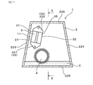
- FIG. 1 is a cross-sectional explanatory view of a reactor cooling device in Embodiment 1
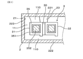
- 2 is a cross-sectional view taken along line II-II in FIG. 3 is a cross-sectional view taken along line III-III in FIG.
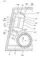
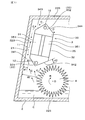
- FIG. 4 is a partially enlarged sectional view of FIG. 1
- FIG. 5 is a cross-sectional explanatory view of a portion of the reactor cooling device in Embodiment 2
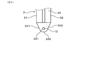
- FIG. 6 is a plan view of the lower fixing portion in the third embodiment
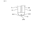
- FIG. 7 is a plan explanatory view of another lower fixing portion in the third embodiment
- FIG. 8 is a cross-sectional explanatory view of the reactor cooling device in the third embodiment.
- the reactor cooling device 1 of the present embodiment has a housing 2, a reactor 3 disposed in the housing 2, and a rotating body 4 as shown in FIG. 1.
- the rotating body 4 is rotatably disposed below the reactor 3 in the housing 2.
- the rotating body 4 and the reactor 3 are disposed so as to overlap at least partially in the rotation radius direction of the rotating body 4. As shown in FIGS. 1 and 2, a part of the rotating body 4 is immersed in the liquid refrigerant C accumulated in the housing 2.
- the reactor cooling device 1 is configured to cool the reactor 3 by bringing the liquid refrigerant C flipped up by the rotating body 4 in rotation into contact with the reactor 3.
- the reactor 3 is disposed along a part of the inner wall surface of the housing 2. As shown in FIG. 1, FIG. 3 and FIG. 4, among the inner wall surfaces, an opposing wall surface 21 facing the reactor 3 from the rotational radius direction of the rotating body 4 and an opposing side surface 31 which is a side surface of the reactor 3 opposing the opposing wall surface 21 The refrigerant flow path 11 is formed between them. The liquid refrigerant C splashed up by the rotating body 4 flows through the refrigerant channel 11.
- the distance d1 between the facing side surface 31 and the facing wall surface 21 in the coolant channel 11 is shorter than the distance d2 between the rotating body 4 and the facing wall surface 21.
- the distances d1 and d2 refer to distances in the normal direction of the facing wall surface 21.
- the reactor 3 includes a heat generating portion 35 that generates heat, and a fixing portion 33 for fixing to the housing 2. At least a part of the fixing portion 33 is a lower fixing portion 331 disposed below the heat generating portion 35.
- the lower fixing portion 331 has an opposite side lower guide surface 341 formed to be connected to the opposite side surface 31.
- the reactor 3 has a back side 32 opposite to the opposite side 31.
- the lower fixing portion 331 has a back side lower guide surface 342 formed to be connected to the back side surface 32.
- the fixing portion 33 further includes an upper fixing portion 332 disposed above the heat generating portion 35.
- the upper fixed portion 332 has an opposing upper guide surface 343 connected to the opposing side surface 31 and a reverse direction upper guide surface 344 connected to the reverse side surface 32.
- the reactor cooling device 1 of the present embodiment has a reactor 3 provided in a transaxle and a gear (i.e., gear) as the rotating body 4. Also, the case of the transaxle is the housing 2. In addition, lubricating oil for lubricating gears and the like in the transaxle is the liquid refrigerant C. Although other gears, electronic components, mechanical elements, and the like are arranged in the housing 2 in addition to the reactor 3 and the rotating body 4, the illustration thereof is omitted.
- an inverter for controlling and driving a motor for supplying a driving force to the transaxle is provided in the vicinity of the transaxle.
- this inverter one disposed in the transaxle can be used as the reactor 3 described above.
- the rotating body 4 is a gear and has a substantially disc shape, and a large number of teeth are formed on the outer peripheral surface.
- the rotating body 4 is pivotally supported at its central portion and configured to rotate with respect to the housing 2. Specifically, the rotating body 4 rotates in the direction of the arrow R in FIG. 4 around the rotation center O. Then, a part of the rotating body 4 is immersed in the liquid refrigerant C stored in the lower part of the housing 2.
- the rotation center O of the rotating body 4 is disposed above the liquid surface of the liquid refrigerant C.
- the housing 2 has a first wall portion 221 and a second wall portion 222 facing each other on both sides in the rotational axis direction of the rotating body 4.
- the first wall 221 and the second wall 222 are connected at their lower ends by the bottom wall 225 and at their upper ends by the ceiling wall 226.
- the first wall 221 and the second wall 222 are the third wall 223 and the fourth wall in the direction orthogonal to both the vertical direction and the rotational axis direction.
- And 224 are linked.
- the third wall 223 and the fourth wall 224 are inclined inward toward the upper side.
- the shape of the above-described case 2 shown in FIGS. 1 to 4 is a rough shape and is not particularly limited.
- the rotating body 4 is disposed at a relatively lower position in the housing 2.
- the reactor 3 is fixed to the first wall portion 211.
- the reactor 3 is fixed to the housing 2 at two fixing parts 33.
- the housing 2 is formed with two bosses 23 projecting inward from the first wall portion 221.
- the lower fixing portion 331 and the upper fixing portion 332 are in contact with the bosses 23, respectively.
- the bolts 12 are respectively inserted into the insertion holes respectively formed in the lower fixing portion 331 and the upper fixing portion 332, and screwed into the female screw formed in the boss 23 for fastening.
- the reactor 3 is thereby fixed to the first wall portion 221 of the housing 2.
- the heat generating portion 35 in the reactor 3 has a coil 351 and a core 352 disposed inside the coil 351.
- the coils 351 are formed in two rows, and the two rows of coils 351 are electrically connected in series to each other.
- the coil 351 and the core 352 are integrated by the mold resin 30.
- the mold resin 30 integrally has two fixing portions 33. That is, the fixing portion 33 is configured by a part of the mold resin 30.
- the fixing portion 33 has a thickness smaller than that of the heat generating portion 35 in the direction parallel to the rotation axis direction of the rotating body 4. In each fixing portion 33, an insertion hole penetrating in the thickness direction is formed.
- the reactor 3 is fixed at the fixing portion 33 by fastening the bolt 12 inserted into the insertion hole to the boss 23.
- the fixing portion 33 is formed such that an end face parallel to the thickness direction is continuous with the side surface of the heat generating portion 35. That is, on the end face of the lower fixing portion 331, the above-mentioned opposite side lower guide surface 341 and the back side lower guide surface 342 are formed. Further, on the end face of the upper fixed portion 332, the above-mentioned opposite side upper guide surface 343 and the back side upper guide surface 344 are formed.
- the reactor 3 is disposed so that the side surface of a part of the heat generating portion 35 is along the inner wall surface of the third wall portion 223. That is, the inner wall surface of the third wall portion 223 is the facing wall surface 21, and the side surface of a part of the heat generating portion 35 of the reactor 3 is the facing side surface 31.
- the distance d1 between the facing wall surface 21 and the facing side surface 31 is, for example, about 10 mm or less.
- a space between the opposing wall surface 21 and the opposing side surface 31 is a refrigerant flow path 11.
- the opposing side surface 31 is formed on the side surface of the coil 351 of one of the two rows of coils 351 constituting the heat generating portion 35 of the reactor 3. That is, the arrangement direction of the two rows of coils 351 is the normal direction of the facing wall surface 21. Therefore, the back side surface 32 is formed on the side surface of the coil 351 of the other row in the coil 351 of the two rows.
- the reactor 3 disposed along the third wall 223 is also inclined with respect to the vertical direction. That is, the opposing side 31 and the back side 32 of the reactor 3 are inclined with respect to the vertical direction.
- the opposite side surface 31 faces obliquely upward, and the opposite side surface 32 points obliquely downward.
- the distance d3 between the reactor 3 and the rotating body 4 is smaller than the radius of the rotating body 4. Further, the upper end of the rotating body 4 is located above the lower end of the reactor 3.
- the rotating body 4 is disposed at a position where it partially overlaps the reactor 3 in the rotation radius direction.
- a part of the rotating body 4 does not overlap with the reactor 3 in the rotation radius direction.
- the whole in the thickness direction of the rotating body 4 may be arranged to overlap the reactor 3 in the radial direction of rotation.
- the reactor 3 is disposed close to the first wall 221 and the second wall 222 of the housing 2 as well. Therefore, the space between the heat generating portion 35 of the reactor 3 and the first wall portion 221 and the second wall portion 222 also serves as the refrigerant flow path 110. That is, in the present embodiment, in addition to the refrigerant flow passage 11 formed between the opposed side surface 31 of the reactor 3 and the opposed wall surface 21 of the housing 2, the refrigerant flow passage 110 is also formed.
- the liquid refrigerant C flows through the refrigerant flow path 11 and the refrigerant flow path 110 to cool the reactor 3. Further, the liquid refrigerant C may come into contact with the reactor 3 in addition to the surfaces facing the refrigerant flow passage 11 and the refrigerant flow passage 110. That is, the liquid refrigerant C also contacts the back side surface 32. Therefore, reactor 3 is also cooled from this back side surface 32.
- the liquid refrigerant C is also lubricating oil, and this lubricating oil is efficiently attached to the heat generating portion 35 of the reactor 3. As a result, while the lubrication in the transaxle is performed, the reactor 3 is also cooled.
- the rotating body 4 and the reactor 3 are disposed so as to overlap in at least a part of the rotational radius direction of the rotating body 4. Therefore, the liquid refrigerant C flipped up with the rotation of the rotating body 4 can be brought into contact with the reactor 3 continuously.
- the reactor 3 is configured to be cooled by bringing the liquid refrigerant C flipped up by the rotating body 4 in rotation in this manner into contact with the reactor 3. Therefore, the reactor 3 can be efficiently cooled with a simple configuration. In addition, it is easy to reduce the cost of the reactor cooling device 1.
- the reactor 3 is disposed along a part of the inner wall surface of the housing 2.
- the coolant channel 11 is formed between the facing wall surface 21 of the housing 2 and the facing side surface 31 of the reactor 3. Therefore, the reactor 3 can be efficiently cooled by the liquid refrigerant C splashed up by the rotating body 4 flowing efficiently to the refrigerant flow path 11. That is, as shown in FIG. 4, with the rotation of the rotating body 4, the stored liquid refrigerant C is flipped up. The bounced liquid refrigerant C moves along the opposing wall 21 so as to crawl upward.
- the opposing wall surface 21 and the opposing side surface 31 are disposed close to each other, and the refrigerant channel 11 is formed therebetween, so that the liquid refrigerant C efficiently contacts the reactor 3 along the refrigerant channel 11, It climbs upwards.
- a part of the liquid refrigerant C which is bounced up by the rotating body 4 also moves upward of the reactor 3 by other paths.
- the liquid refrigerant C which has moved to the upper side of the reactor 3 adheres to the inner wall surface or the like of the ceiling wall portion 226. Then, as shown by a broken arrow C, these liquid refrigerants C flow down by gravity. Also at this time, the liquid refrigerant C travels along the opposite side surface 31 of the reactor 3 along the refrigerant flow path 11. Therefore, the reactor 3 is cooled efficiently.
- the distance d1 between the facing side surface 31 and the facing wall surface 21 in the refrigerant flow path 11 is shorter than the distance d2 between the rotating body 4 and the facing wall surface 21. Therefore, the liquid refrigerant C that has entered the refrigerant flow passage 11 can easily contact the opposite side surface 31 of the reactor 3 efficiently.
- the lower fixing portion 331 of the reactor 3 also has an opposing lower guide surface 341 formed to be connected to the opposing side surface 31.
- the lower fixed portion 331 of the reactor 3 has a back direction side lower guide surface 342 formed to be connected to the back direction side surface 32.
- the liquid refrigerant C that has collided with the lower fixed portion 331 can be smoothly led to the back side surface 32 as well. That is, the liquid refrigerant C that has collided with the lower fixed portion 331 is guided to the back side 32 along the back side lower guide surface 342. Thereby, more liquid refrigerant C can be led to the back side 32.
- the heat generating portion 35 of the reactor 3 can be easily cooled from both the opposite side surface 31 and the back direction side surface 32. As a result, the cooling efficiency of the reactor 3 can be further improved.
- the upper fixed portion 332 of the reactor 3 has an opposing upper guide surface 343 connected to the opposing side surface 31 and a reverse direction upper guide surface 344 connected to the reverse surface 32.
- the liquid refrigerant C also flows between the reactor 3 and the first wall portion 221 or between the reactor 3 and the second wall portion 222. Therefore, the liquid refrigerant C is also cooled from the surface of the reactor 3 facing the first wall 221 and the surface facing the second wall 222.
- the boundary 345 between the opposite side lower guide surface 341 and the back side lower guide surface 342 is closer to the opposite side 31 than the center of the heat generating portion 35 in the normal direction of the opposite side 31.
- On the side close to the The area of the back side lower guide surface 342 is larger than that of the opposite side lower guide surface 341.
- the other configuration is the same as that of the first embodiment.
- symbol used in Embodiment 2 or subsequent ones represents the component similar to the thing in already-appeared embodiment, etc., unless shown.
- the outer shape of the lower fixing portion 331 is a curved surface. That is, in the lower fixing portion 331 shown in FIG. 6, the boundary 345 between the opposing lower guide surface 341 and the back side lower guiding surface 342 in the lower fixing portion 331 is curved. Therefore, the opposite side lower guide surface 341 and the back side lower guide surface 342 have curved portions near the boundary 345 while having flat portions. Thereby, the opposite side lower guide surface 341 and the back side lower guide surface 342 smoothly connect with each other.
- fixed part 331 shown in FIG. 7 is formed in substantially circular arc shape. Therefore, the opposite side lower guide surface 341 and the back side lower guide surface 342 are curved surfaces respectively formed in a part of a substantially arc shape.
- the other configuration is the same as that of the first embodiment.
- the opposite side lower guide surface 341 can be smoothly connected to the opposite side surface 31.
- the back side lower guide surface 342 can be smoothly connected to the back side 32.
- the shape of the lower fixing portion 331 shown in FIG. 7 facilitates connecting the opposite side lower guide surface 341 and the back side lower guide surface 342 to the opposite side surface 31 and the back direction side surface 32 more smoothly.
- it has the same operation effect as Embodiment 1.
- the upper fixing portion 332 may also have the same shape as the lower fixing portion 331 in the present embodiment.
- This embodiment is a form of reactor cooling device 1 arranged so that opposite side 31 of reactor 3 may be along the perpendicular direction, as shown in FIG.
- the third wall 223 of the housing 2 is erected in the vertical direction.
- the reactor 3 is fixed to the housing 2 so that the opposing side surface 31 is along the opposing wall surface 21 which is the inner wall surface of the third wall portion 223 erected in the vertical direction.
- the other configuration is the same as that of the first embodiment.
- the reactor 3 can be cooled efficiently. In addition, it has the same operation effect as Embodiment 1.
- the opposing side surface 31 of the reactor 3 can also be arrange
- the opposite side surface 31 can be disposed to be inclined with respect to the opposite wall surface 21.
Landscapes
- Engineering & Computer Science (AREA)
- Power Engineering (AREA)
- Chemical & Material Sciences (AREA)
- Combustion & Propulsion (AREA)
- Transportation (AREA)
- Mechanical Engineering (AREA)
- Physics & Mathematics (AREA)
- Cooling Or The Like Of Electrical Apparatus (AREA)
- General Details Of Gearings (AREA)
- Transformer Cooling (AREA)
- Plasma & Fusion (AREA)
- General Engineering & Computer Science (AREA)
- High Energy & Nuclear Physics (AREA)
Abstract
リアクトル冷却装置(1)は、筐体(2)と、筐体(2)内に配置されたリアクトル(3)と、筐体(2)内におけるリアクトル(3)の下方において回転可能に配された回転体(4)と、を有する。回転体(4)とリアクトル(3)とは、少なくとも一部において、回転体(4)の回転半径方向に重なるように配置されている。筐体(2)内に溜まった液冷媒(C)に、回転体(4)の一部が浸漬している。回転する回転体(4)によって跳ね上げられた液冷媒(C)を、リアクトル(3)に接触させることにより、リアクトル(3)を冷却するよう構成されている。
Description
本出願は、2017年8月25日に出願された日本出願番号2017-162368号に基づくもので、ここにその記載内容を援用する。
本開示は、液冷媒をリアクトルに接触させて冷却するよう構成されたリアクトル冷却装置に関する。
リアクトルに潤滑油を接触させてリアクトルを冷却するよう構成した構造が、特許文献1に開示されている。特許文献1に開示された構造においては、車両の駆動装置に設けられたリアクトルが、駆動装置内における潤滑油にて冷却されるよう構成されている。より具体的には、潤滑油が、ディファレンシャルギヤの回転に応じて跳ね上げられて、上方に位置する減速ギヤに付着する。減速ギヤに付着した潤滑油は、減速ギヤの回転に応じてさらに跳ね上げられる。そして、ディファレンシャルギヤと減速ギヤとによってリアクトルよりも上方に跳ね上げられた潤滑油は、オイル通路を流れてオイル室に流入して、リアクトルを冷却する。
特許文献1に開示された構造は、潤滑油をリアクトルに到達させるにあたり、ディファレンシャルギヤと減速ギヤ、さらにはオイル通路及びオイル室を経由させることとなる。それゆえ、構造が複雑となり、設計自由度が低下しやすい。また、製造コストも高くなりやすい。
本開示は、簡素な構造にて、コスト低減しやすい、リアクトル冷却装置を提供しようとするものである。
本開示の一態様は、筐体と、
上記筐体内に配置されたリアクトルと、
上記筐体内における上記リアクトルの下方において回転可能に配された回転体と、を有し、
上記回転体と上記リアクトルとは、少なくとも一部において、上記回転体の回転半径方向に重なるように配置されており、
上記筐体内に溜まった液冷媒に、上記回転体の一部が浸漬しており、
回転する上記回転体によって跳ね上げられた上記液冷媒を、上記リアクトルに接触させることにより、上記リアクトルを冷却するよう構成されている、リアクトル冷却装置にある。
上記筐体内に配置されたリアクトルと、
上記筐体内における上記リアクトルの下方において回転可能に配された回転体と、を有し、
上記回転体と上記リアクトルとは、少なくとも一部において、上記回転体の回転半径方向に重なるように配置されており、
上記筐体内に溜まった液冷媒に、上記回転体の一部が浸漬しており、
回転する上記回転体によって跳ね上げられた上記液冷媒を、上記リアクトルに接触させることにより、上記リアクトルを冷却するよう構成されている、リアクトル冷却装置にある。
上記リアクトル冷却装置において、上記回転体と上記リアクトルとは、少なくとも一部において、回転体の回転半径方向に重なるように配置されている。それゆえ、回転体の回転に伴って跳ね上げられた液冷媒を、リアクトルに連続的に接触させることができる。
このようにして、回転する回転体によって跳ね上げられた液冷媒を、リアクトルに接触させることにより、リアクトルを冷却するよう構成されている。それゆえ、簡素な構成にて、リアクトルを効率的に冷却することができる。また、リアクトル冷却装置のコスト低減を図りやすい。
このようにして、回転する回転体によって跳ね上げられた液冷媒を、リアクトルに接触させることにより、リアクトルを冷却するよう構成されている。それゆえ、簡素な構成にて、リアクトルを効率的に冷却することができる。また、リアクトル冷却装置のコスト低減を図りやすい。
以上のごとく、上記態様によれば、簡素な構造にて、コスト低減しやすい、リアクトル冷却装置を提供することを目的とする。
なお、特許請求の範囲を解決する手段に記載した括弧内の符号は、後述する実施形態に記載の具体的手段との対応関係を示すものであり、本開示の技術的範囲を限定するものではない。
なお、特許請求の範囲を解決する手段に記載した括弧内の符号は、後述する実施形態に記載の具体的手段との対応関係を示すものであり、本開示の技術的範囲を限定するものではない。
本開示についての上記目的およびその他の目的、特徴や利点は、添付の図面を参照しながら下記の詳細な記述により、より明確になる。その図面は、
図1は、実施形態1における、リアクトル冷却装置の断面説明図であり、
図2は、図1のII-II線矢視断面図であり、
図3は、図2のIII-III線矢視断面図であり、
図4は、図1の部分拡大断面説明図であり、
図5は、実施形態2における、リアクトル冷却装置の一部の断面説明図であり、
図6は、実施形態3における、下側固定部の平面説明図であり、
図7は、実施形態3における、他の下側固定部の平面説明図であり、
図8は、実施形態3における、リアクトル冷却装置の断面説明図である。
(実施形態1)
リアクトル冷却装置に係る実施形態について、図1~図4を参照して説明する。
本実施形態のリアクトル冷却装置1は、図1に示すごとく、筐体2と、筐体2内に配置されたリアクトル3と、回転体4とを有する。回転体4は、筐体2内におけるリアクトル3の下方において回転可能に配されている。
リアクトル冷却装置に係る実施形態について、図1~図4を参照して説明する。
本実施形態のリアクトル冷却装置1は、図1に示すごとく、筐体2と、筐体2内に配置されたリアクトル3と、回転体4とを有する。回転体4は、筐体2内におけるリアクトル3の下方において回転可能に配されている。
図2に示すごとく、回転体4とリアクトル3とは、少なくとも一部において、回転体4の回転半径方向に重なるように配置されている。
図1、図2に示すごとく、筐体2内に溜まった液冷媒Cに、回転体4の一部が浸漬している。
リアクトル冷却装置1は、回転する回転体4によって跳ね上げられた液冷媒Cを、リアクトル3に接触させることにより、リアクトル3を冷却するよう構成されている。
図1、図2に示すごとく、筐体2内に溜まった液冷媒Cに、回転体4の一部が浸漬している。
リアクトル冷却装置1は、回転する回転体4によって跳ね上げられた液冷媒Cを、リアクトル3に接触させることにより、リアクトル3を冷却するよう構成されている。
リアクトル3は、筐体2の内壁面の一部に沿うように配置されている。図1、図3、図4に示すごとく、内壁面のうち回転体4の回転半径方向からリアクトル3と対向する対向壁面21と、対向壁面21に対向するリアクトル3の側面である対向側面31との間には、冷媒流路11が形成されている。冷媒流路11には、回転体4によって跳ね上げられた液冷媒Cが流れる。
図4に示すごとく、冷媒流路11における対向側面31と対向壁面21との間の距離d1は、回転体4と対向壁面21との間の距離d2よりも短い。ここで、距離d1、d2は、対向壁面21の法線方向における距離をいう。
リアクトル3は、発熱する発熱部35と、筐体2に固定するための固定部33とを備えている。固定部33の少なくとも一部は、発熱部35よりも下側に配されている下側固定部331である。下側固定部331は、対向側面31に繋がるように形成された対向側下方ガイド面341を有する。
リアクトル3は、対向側面31と反対側の背向側面32を有する。下側固定部331は、背向側面32に繋がるように形成された背向側下方ガイド面342を有する。
固定部33として、発熱部35よりも上側に配された上側固定部332をさらに有する。上側固定部332は、対向側面31につながる対向側上方ガイド面343と、背向側面32につながる背向側上方ガイド面344とを有する。
固定部33として、発熱部35よりも上側に配された上側固定部332をさらに有する。上側固定部332は、対向側面31につながる対向側上方ガイド面343と、背向側面32につながる背向側上方ガイド面344とを有する。
本実施形態のリアクトル冷却装置1は、トランスアクスル内に設けられたリアクトル3と、回転体4としてのギヤ(すなわち歯車)とを有する。また、トランスアクスルのケースが筐体2である。また、トランスアクスルにおけるギヤ等を潤滑するための潤滑油が、液冷媒Cとなる。筐体2内には、リアクトル3及び回転体4の他にも、他のギヤ、電子部品、機械要素等が配置されているが、これらの図示は省略している。
また、図示を省略するが、トランスアクスルへの駆動力を供給するモータを制御駆動するインバータが、トランスアクスルの近傍に設けられる。このインバータの一部品として、トランスアクスル内に配置されているものを、上記のリアクトル3とすることができる。
上述のように、回転体4はギヤであり、略円盤状を有すると共に、外周面に多数の歯が形成されている。また、回転体4は、その中心部において軸支されて、筐体2に対して回転するよう構成されている。具体的には、回転体4は、回転中心Oを中心に、図4の矢印Rの向きに回転する。そして、筐体2の下部に貯留される液冷媒Cに、回転体4の一部が浸漬している。本実施形態においては、回転体4の回転中心Oが、液冷媒Cの液面よりも上側に配置されている。
図2、図3に示すごとく、筐体2は、回転体4における回転軸方向の両側に、互いに対向する第1壁部221と第2壁部222とを有する。これらの第1壁部221と第2壁部222とは、その下端において底壁部225によって連結され、上端において天井壁部226によって連結されている。また、図1、図3に示すごとく、第1壁部221と第2壁部222とは、上下方向と回転軸方向との双方に直交する方向において、第3壁部223と第4壁部224とによって連結されている。第3壁部223と第4壁部224とは、上側へ行くほど内側へ向かうように傾斜している。なお、図1~図4に示した上述の筐体2の形状は、概略の形状であり、特に限定されるものではない。
筐体2内における比較的下方の位置に、回転体4が配置されている。回転体4の直上において、リアクトル3は、第1壁部211に固定されている。リアクトル3は、筐体2に対して2つの固定部33において、固定されている。図2に示すごとく、筐体2には、第1壁部221から内側へ突出した2つのボス23が形成されている。これらのボス23に、下側固定部331と上側固定部332とを、それぞれ当接させている。そして、下側固定部331と上側固定部332とにそれぞれ形成された挿通孔に、それぞれボルト12を挿通すると共に、ボス23に形成された雌ネジに螺合させて、締結している。これにより、リアクトル3は、筐体2における第1壁部221に固定されている。
図3に示すごとく、リアクトル3における発熱部35は、コイル351とその内側に配されたコア352とを有する。図3、図4に示すごとく、コイル351は、2列形成されており、2列のコイル351は、互いに電気的に直列に接続されている。コイル351とコア352とはモールド樹脂30にて一体化されている。モールド樹脂30は、2つの固定部33を一体的に有する。つまり、固定部33は、モールド樹脂30の一部によって構成されている。固定部33は、回転体4の回転軸方向と平行な方向において、発熱部35よりも厚みが小さい。そして、各固定部33には、厚み方向に貫通した挿通孔が形成されている。この挿通孔に挿通されたボルト12を、ボス23に締結することで、リアクトル3が固定部33において固定されている。
固定部33は、厚み方向に平行な端面が、発熱部35の側面に連続するように形成されている。つまり、下側固定部331の端面に、上述の対向側下方ガイド面341及び背向側下方ガイド面342が形成されている。また、上側固定部332の端面に、上述の対向側上方ガイド面343及び背向側上方ガイド面344が形成されている。
図3、図4に示すごとく、リアクトル3は、発熱部35の一部の側面を、第3壁部223の内壁面に沿わせるように配置されている。つまり、第3壁部223の内壁面が、対向壁面21となり、リアクトル3の発熱部35の一部の側面が対向側面31となる。対向壁面21と対向側面31との間の距離d1は、例えば10mm以下程度である。そして、対向壁面21と対向側面31との間の空間が冷媒流路11となっている。
なお、対向側面31は、リアクトル3の発熱部35を構成する2列のコイル351のうち、一方の列のコイル351の側面に形成されることとなる。つまり、2列のコイル351の配列方向は、対向壁面21の法線方向となっている。それゆえ、2列のコイル351における他方の列のコイル351の側面に、背向側面32が形成される。
上述のように、第3壁部223は鉛直方向に対して傾斜しているため、第3壁部223に沿って配設されたリアクトル3も、鉛直方向に対して傾斜することとなる。すなわち、リアクトル3の対向側面31及び背向側面32は、鉛直方向に対して傾斜している。また、対向側面31は斜め上方を向き、背向側面32は斜め下方を向くこととなる。
本実施形態において、リアクトル3と回転体4との間の距離d3は、回転体4の半径よりも小さい。また、回転体4の上端は、リアクトル3の下端よりも上側に位置している。
また、図2に示すごとく、回転体4は、回転半径方向において、リアクトル3に対して部分的に重なる位置に配されている。また、回転半径方向において、回転体4の一部は、リアクトル3と重なっていない。ただし、回転体4の厚み方向の全体が、回転半径方向において、リアクトル3と重なるように配置されていてもよい。
図2、図3に示すごとく、リアクトル3は、筐体2の第1壁部221及び第2壁部222に対しても、近接して配置されている。それゆえ、リアクトル3の発熱部35と、第1壁部221及び第2壁部222との間の空間も、冷媒流路110となる。すなわち、本実施形態においては、リアクトル3の対向側面31と筐体2の対向壁面21との間に形成される冷媒流路11の他に、上記の冷媒流路110も形成されている。
これらの冷媒流路11及び冷媒流路110に液冷媒Cが流れることで、リアクトル3が冷却される。また、リアクトル3は、これらの冷媒流路11及び冷媒流路110に面した表面以外にも、液冷媒Cが接触し得る。すなわち、背向側面32にも、液冷媒Cは接触する。それゆえ、この背向側面32からも、リアクトル3は冷却される。
特に本実施形態においては、液冷媒Cが潤滑油でもあり、この潤滑油が、効率的にリアクトル3の発熱部35に付着するようにしている。これにより、トランスアクスル内における潤滑を行いながら、リアクトル3の冷却をも行われることとなる。
次に、本実施形態の作用効果につき説明する。
上記リアクトル冷却装置1において、回転体4とリアクトル3とは、少なくとも一部において、回転体4の回転半径方向に重なるように配置されている。それゆえ、回転体4の回転に伴って跳ね上げられた液冷媒Cを、リアクトル3に連続的に接触させることができる。
上記リアクトル冷却装置1において、回転体4とリアクトル3とは、少なくとも一部において、回転体4の回転半径方向に重なるように配置されている。それゆえ、回転体4の回転に伴って跳ね上げられた液冷媒Cを、リアクトル3に連続的に接触させることができる。
このようにして、回転する回転体4によって跳ね上げられた液冷媒Cを、リアクトル3に接触させることにより、リアクトル3を冷却するよう構成されている。それゆえ、簡素な構成にて、リアクトル3を効率的に冷却することができる。また、リアクトル冷却装置1のコスト低減を図りやすい。
リアクトル3は、筐体2の内壁面の一部に沿うように配置されている。そして、筐体2の対向壁面21と、リアクトル3の対向側面31との間に、冷媒流路11が形成されている。それゆえ、回転体4によって跳ね上げられた液冷媒Cが、この冷媒流路11に効率的に流れることで、リアクトル3を効率的に冷却することができる。つまり、図4に示すごとく、回転体4の回転に伴い、貯留されていた液冷媒Cが跳ね上げられる。跳ね上げられた液冷媒Cは、対向壁面21に沿って上方へ這い上がるように移動する。対向壁面21と対向側面31とが近接配置されて、その間に冷媒流路11が形成されているため、この冷媒流路11に沿って、液冷媒Cが効率的にリアクトル3に接触しながら、その上方へ這い上がる。また、その他の経路によっても、回転体4によって跳ね上げられる液冷媒Cの一部は、リアクトル3の上方へ移動する。リアクトル3の上方へ移動した液冷媒Cは、天井壁部226の内壁面などに付着する。そして、これらの液冷媒Cは、破線矢印Cに示すように、重力によって流下する。このときも、液冷媒Cは、冷媒流路11に沿って、リアクトル3の対向側面31を伝うこととなる。それゆえ、リアクトル3が効率的に冷却される。
また、冷媒流路11における対向側面31と対向壁面21との間の距離d1は、回転体4と対向壁面21との間の距離d2よりも短い。そのため、冷媒流路11に入った液冷媒Cは、リアクトル3の対向側面31に効率的に接触しやすくなる。
また、リアクトル3の下側固定部331は、対向側面31に繋がるように形成された対向側下方ガイド面341を有する。これにより、回転体4によって跳ね上げられた液冷媒Cの一部が、リアクトル3の下側固定部331に衝突したとき、その液冷媒Cを円滑に対向側面31に導くことができる。つまり、下側固定部331に衝突した液冷媒Cは、対向側下方ガイド面341に沿って、対向側面31に導かれる。これにより、より多くの液冷媒Cを、対向側面31に導くことができ、リアクトル3の冷却を効率的に行いやすい。
また、リアクトル3の下側固定部331は、背向側面32に繋がるように形成された背向側下方ガイド面342を有する。これにより、下側固定部331に衝突した液冷媒Cは、背向側面32にも円滑に導くことができる。つまり、下側固定部331に衝突した液冷媒Cは、背向側下方ガイド面342に沿って、背向側面32に導かれる。これにより、より多くの液冷媒Cを、背向側面32に導くことができる。その結果、リアクトル3の発熱部35を、対向側面31と背向側面32との双方から冷却しやすくなる。その結果、よりリアクトル3の冷却効率を向上させることができる。
さらに、リアクトル3の上側固定部332は、対向側面31につながる対向側上方ガイド面343と、背向側面32につながる背向側上方ガイド面344とを有する。これにより、上述したように、リアクトル3の上方へ移動した液冷媒Cが流下する際に、リアクトル3の対向側面31及び背向側面32に液冷媒Cが円滑に導かれる。すなわち、上方に移動した液冷媒Cが、まず上側固定部332に付着する。このとき、対向側上方ガイド面343に到達した液冷媒Cは、対向側面31に円滑に導かれる。また、背向側上方ガイド面344に到達した液冷媒Cは、背向側面32に円滑に導かれる。このように、リアクトル3の上方から流下する液冷媒Cも、対向側面31及び背向側面32に効率的に導くことができる。
なお、本実施形態においては、液冷媒Cは、リアクトル3と第1壁部221との間や、リアクトル3と第2壁部222との間にも、流れる。それゆえ、リアクトル3における、第1壁部221と対向する表面や、第2壁部222と対向する表面からも、液冷媒Cを介して冷却される。
以上のごとく、本実施形態によれば、簡素な構造にて、コスト低減しやすい、リアクトル冷却装置を提供することができる。
(実施形態2)
本実施形態は、図5に示すごとく、対向側下方ガイド面341と背向側下方ガイド面342との境界部345は、対向側面31の法線方向における発熱部35の中央よりも対向側面31に近い側に、配されている形態である。
対向側下方ガイド面341よりも、背向側下方ガイド面342の方が、面積が広くなっている。
本実施形態は、図5に示すごとく、対向側下方ガイド面341と背向側下方ガイド面342との境界部345は、対向側面31の法線方向における発熱部35の中央よりも対向側面31に近い側に、配されている形態である。
対向側下方ガイド面341よりも、背向側下方ガイド面342の方が、面積が広くなっている。
その他の構成は、実施形態1と同様である。なお、実施形態2以降において用いた符号のうち、既出の実施形態において用いた符号と同一のものは、特に示さない限り、既出の実施形態におけるものと同様の構成要素等を表す。
本実施形態においては、回転体4によって跳ね上げられた液冷媒Cを、より多く、背向側下方ガイド面342に沿って、背向側面32に導くことができる。その結果、リアクトル3の発熱部35を、対向側面31及び背向側面32の双方から、より効率的に冷却することができる。
その他、実施形態1と同様の作用効果を有する。
その他、実施形態1と同様の作用効果を有する。
(実施形態3)
本実施形態は、図6、図7に示すごとく、下側固定部331の外形に曲面を用いた形態である。
すなわち、図6に示す下側固定部331は、下側固定部331における対向側下方ガイド面341と背向側下方ガイド面342との境界部345を、曲面状にしている。それゆえ、対向側下方ガイド面341と背向側下方ガイド面342とは、それぞれ平面部を持ちながら、その境界部345付近において、曲面部を有することとなる。これにより、対向側下方ガイド面341と背向側下方ガイド面342とは、互いに滑らかにつながる。
本実施形態は、図6、図7に示すごとく、下側固定部331の外形に曲面を用いた形態である。
すなわち、図6に示す下側固定部331は、下側固定部331における対向側下方ガイド面341と背向側下方ガイド面342との境界部345を、曲面状にしている。それゆえ、対向側下方ガイド面341と背向側下方ガイド面342とは、それぞれ平面部を持ちながら、その境界部345付近において、曲面部を有することとなる。これにより、対向側下方ガイド面341と背向側下方ガイド面342とは、互いに滑らかにつながる。
また、図7に示す下側固定部331は、全体が略円弧状に形成されている。それゆえ、対向側下方ガイド面341及び背向側下方ガイド面342は、それぞれ略円弧形状の一部に形成される曲面となる。
その他の構成は、実施形態1と同様である。
その他の構成は、実施形態1と同様である。
本実施形態においても、対向側下方ガイド面341を対向側面31に滑らかにつなぐことができる。また、背向側下方ガイド面342を背向側面32に滑らかにつなぐことができる。特に、図7に示す下側固定部331の形状は、対向側下方ガイド面341及び背向側下方ガイド面342を、それぞれ対向側面31及び背向側面32に、より滑らかにつなぎやすくなる。
その他、実施形態1と同様の作用効果を有する。
なお、上側固定部332についても、本実施形態における下側固定部331と同様の形状とすることもできる。
その他、実施形態1と同様の作用効果を有する。
なお、上側固定部332についても、本実施形態における下側固定部331と同様の形状とすることもできる。
(実施形態4)
本実施形態は、図8に示すごとく、リアクトル3の対向側面31が鉛直方向に沿うように配置した、リアクトル冷却装置1の形態である。
本実施形態においては、筐体2の第3壁部223が、鉛直方向に立設している。そして、図8に示すごとく、鉛直方向に立設された第3壁部223の内壁面である対向壁面21に、対向側面31が沿うように、リアクトル3を筐体2に固定してある。
その他の構成は、実施形態1と同様である。
本実施形態は、図8に示すごとく、リアクトル3の対向側面31が鉛直方向に沿うように配置した、リアクトル冷却装置1の形態である。
本実施形態においては、筐体2の第3壁部223が、鉛直方向に立設している。そして、図8に示すごとく、鉛直方向に立設された第3壁部223の内壁面である対向壁面21に、対向側面31が沿うように、リアクトル3を筐体2に固定してある。
その他の構成は、実施形態1と同様である。
本実施形態においても、実施形態1と同様に、リアクトル3を効率的に冷却することができる。
その他、実施形態1と同様の作用効果を有する。
その他、実施形態1と同様の作用効果を有する。
なお、リアクトル3の対向側面31を、斜め下方に向くように、傾斜して配置することもできる。また、対向側面31を、対向壁面21に対して傾斜して配置することもできる。
本開示は上記各実施形態に限定されるものではなく、その要旨を逸脱しない範囲において種々の実施形態に適用することが可能である。
本開示は、実施形態に準拠して記述されたが、本開示は当該実施形態や構造に限定されるものではないと理解される。本開示は、様々な変形例や均等範囲内の変形をも包含する。加えて、様々な組み合わせや形態、さらには、それらに一要素のみ、それ以上、あるいはそれ以下、を含む他の組み合わせや形態をも、本開示の範疇や思想範囲に入るものである。
Claims (7)
- 筐体(2)と、
上記筐体内に配置されたリアクトル(3)と、
上記筐体内における上記リアクトルの下方において回転可能に配された回転体(4)と、を有し、
上記回転体と上記リアクトルとは、少なくとも一部において、上記回転体の回転半径方向に重なるように配置されており、
上記筐体内に溜まった液冷媒(C)に、上記回転体の一部が浸漬しており、
回転する上記回転体によって跳ね上げられた上記液冷媒を、上記リアクトルに接触させることにより、上記リアクトルを冷却するよう構成されている、リアクトル冷却装置(1)。 - 上記リアクトルは、上記筐体の内壁面の一部に沿うように配置されており、上記内壁面のうち上記回転体の回転半径方向から上記リアクトルと対向する対向壁面(21)と、該対向壁面に対向する上記リアクトルの側面である対向側面(31)との間には、上記回転体によって跳ね上げられた上記液冷媒が流れる冷媒流路(11)が形成されている、請求項1に記載のリアクトル冷却装置。
- 上記冷媒流路における上記対向側面と上記対向壁面との間の距離(d1)は、上記回転体と上記対向壁面との間の距離(d2)よりも短い、請求項2に記載のリアクトル冷却装置。
- 上記リアクトルは、発熱する発熱部(35)と、上記筐体に固定するための固定部(33)とを備えており、上記固定部の少なくとも一部は、上記発熱部よりも下側に配されている下側固定部(331)であり、該下側固定部は、上記対向側面に繋がるように形成された対向側下方ガイド面(341)を有する、請求項2又は3に記載のリアクトル冷却装置。
- 上記リアクトルは、上記対向側面と反対側の背向側面(32)を有し、上記下側固定部は、上記背向側面に繋がるように形成された背向側下方ガイド面(342)を有する、請求項4に記載のリアクトル冷却装置。
- 上記対向側下方ガイド面と上記背向側下方ガイド面との境界部(345)は、上記対向側面の法線方向における上記発熱部の中央よりも上記対向側面に近い側に、配されている、請求項5に記載のリアクトル冷却装置。
- 上記固定部として、上記発熱部よりも上側に配された上側固定部(332)をさらに有し、該上側固定部は、上記対向側面につながる対向側上方ガイド面(343)と、上記背向側面につながる背向側上方ガイド面(344)とを有する、請求項5又は6に記載のリアクトル冷却装置。
Priority Applications (2)
| Application Number | Priority Date | Filing Date | Title |
|---|---|---|---|
| CN201880054865.2A CN111033652B (zh) | 2017-08-25 | 2018-08-24 | 电抗器冷却装置 |
| US16/799,167 US11376944B2 (en) | 2017-08-25 | 2020-02-24 | Reactor cooling device |
Applications Claiming Priority (2)
| Application Number | Priority Date | Filing Date | Title |
|---|---|---|---|
| JP2017-162368 | 2017-08-25 | ||
| JP2017162368A JP6708186B2 (ja) | 2017-08-25 | 2017-08-25 | リアクトル冷却装置 |
Related Child Applications (1)
| Application Number | Title | Priority Date | Filing Date |
|---|---|---|---|
| US16/799,167 Continuation US11376944B2 (en) | 2017-08-25 | 2020-02-24 | Reactor cooling device |
Publications (1)
| Publication Number | Publication Date |
|---|---|
| WO2019039596A1 true WO2019039596A1 (ja) | 2019-02-28 |
Family
ID=65438927
Family Applications (1)
| Application Number | Title | Priority Date | Filing Date |
|---|---|---|---|
| PCT/JP2018/031415 Ceased WO2019039596A1 (ja) | 2017-08-25 | 2018-08-24 | リアクトル冷却装置 |
Country Status (4)
| Country | Link |
|---|---|
| US (1) | US11376944B2 (ja) |
| JP (1) | JP6708186B2 (ja) |
| CN (1) | CN111033652B (ja) |
| WO (1) | WO2019039596A1 (ja) |
Citations (4)
| Publication number | Priority date | Publication date | Assignee | Title |
|---|---|---|---|---|
| JP2008072813A (ja) * | 2006-09-13 | 2008-03-27 | Toyota Motor Corp | 車両の駆動装置 |
| JP2011228547A (ja) * | 2010-04-21 | 2011-11-10 | Toyota Industries Corp | リアクトルの冷却構造 |
| JP2012170177A (ja) * | 2011-02-10 | 2012-09-06 | Toyota Motor Corp | 電力制御装置の搭載構造 |
| JP2015046481A (ja) * | 2013-08-28 | 2015-03-12 | 日立金属株式会社 | リアクトル |
Family Cites Families (7)
| Publication number | Priority date | Publication date | Assignee | Title |
|---|---|---|---|---|
| US4258348A (en) * | 1979-11-13 | 1981-03-24 | Stb Transformer Company | Current measuring transformer |
| JP4591312B2 (ja) | 2005-11-01 | 2010-12-01 | トヨタ自動車株式会社 | 車両の駆動装置 |
| CN1822258A (zh) * | 2006-03-17 | 2006-08-23 | 中国科学院电工研究所 | 一种喷淋式蒸发冷却变压器 |
| CN201294146Y (zh) * | 2008-11-04 | 2009-08-19 | 上海置信电气非晶有限公司 | 一种非晶合金35kV油浸式风电变压器 |
| EP2955047B1 (en) * | 2013-05-31 | 2018-09-05 | Aisin AW Co., Ltd. | Vehicle drive device |
| EP3024126A1 (en) * | 2014-11-20 | 2016-05-25 | Siemens Aktiengesellschaft | Cooling arrangement |
| KR20160134500A (ko) * | 2015-05-13 | 2016-11-23 | 페어차일드코리아반도체 주식회사 | 평면형 자기 소자 |
-
2017
- 2017-08-25 JP JP2017162368A patent/JP6708186B2/ja active Active
-
2018
- 2018-08-24 CN CN201880054865.2A patent/CN111033652B/zh active Active
- 2018-08-24 WO PCT/JP2018/031415 patent/WO2019039596A1/ja not_active Ceased
-
2020
- 2020-02-24 US US16/799,167 patent/US11376944B2/en active Active
Patent Citations (4)
| Publication number | Priority date | Publication date | Assignee | Title |
|---|---|---|---|---|
| JP2008072813A (ja) * | 2006-09-13 | 2008-03-27 | Toyota Motor Corp | 車両の駆動装置 |
| JP2011228547A (ja) * | 2010-04-21 | 2011-11-10 | Toyota Industries Corp | リアクトルの冷却構造 |
| JP2012170177A (ja) * | 2011-02-10 | 2012-09-06 | Toyota Motor Corp | 電力制御装置の搭載構造 |
| JP2015046481A (ja) * | 2013-08-28 | 2015-03-12 | 日立金属株式会社 | リアクトル |
Also Published As
| Publication number | Publication date |
|---|---|
| US20200194136A1 (en) | 2020-06-18 |
| JP2019041012A (ja) | 2019-03-14 |
| JP6708186B2 (ja) | 2020-06-10 |
| CN111033652A (zh) | 2020-04-17 |
| US11376944B2 (en) | 2022-07-05 |
| CN111033652B (zh) | 2021-09-21 |
Similar Documents
| Publication | Publication Date | Title |
|---|---|---|
| JP7310367B2 (ja) | 駆動装置 | |
| CN102640401B (zh) | 定子的冷却构造 | |
| TWI792763B (zh) | 動力傳遞裝置、馬達單元以及車輛 | |
| CN108237893A (zh) | 混合动力车辆及混合动力车辆的润滑结构 | |
| CN113048195B (zh) | 正交减速装置 | |
| US12331829B2 (en) | Power transmission device | |
| JP2015089748A (ja) | モータ駆動ユニットの冷却構造 | |
| CN104995438A (zh) | 动力传递装置 | |
| JP2015034581A (ja) | 車両用変速機のオイル供給装置 | |
| WO2021161566A1 (ja) | インバータ装置、モータ、モータユニット | |
| US12392406B2 (en) | Unit | |
| US20200153292A1 (en) | Stator unit of rotary electric machine | |
| JPWO2018030322A1 (ja) | 駆動装置 | |
| JPWO2018030323A1 (ja) | 駆動装置 | |
| WO2019039596A1 (ja) | リアクトル冷却装置 | |
| US1639680A (en) | Machine element | |
| KR20220012091A (ko) | 모터 구동 모듈 | |
| JP5410562B2 (ja) | 動力伝達機構の潤滑装置 | |
| JP5998662B2 (ja) | 車両用インバータの冷却構造 | |
| JP7449777B2 (ja) | 回転電機 | |
| CN110925404B (zh) | 导油件、齿轮箱壳及齿轮箱 | |
| JP2005061617A (ja) | 手動変速機の潤滑構造 | |
| JP5808351B2 (ja) | 自動変速機における潤滑油の誘導構造 | |
| KR102544771B1 (ko) | 로터 조립체 및 이를 포함하는 모터 | |
| JP4931469B2 (ja) | 駆動装置、画像形成装置 |
Legal Events
| Date | Code | Title | Description |
|---|---|---|---|
| 121 | Ep: the epo has been informed by wipo that ep was designated in this application |
Ref document number: 18848565 Country of ref document: EP Kind code of ref document: A1 |
|
| NENP | Non-entry into the national phase |
Ref country code: DE |
|
| 122 | Ep: pct application non-entry in european phase |
Ref document number: 18848565 Country of ref document: EP Kind code of ref document: A1 |