WO2019035219A1 - Coated cutting tool - Google Patents
Coated cutting tool Download PDFInfo
- Publication number
- WO2019035219A1 WO2019035219A1 PCT/JP2017/043027 JP2017043027W WO2019035219A1 WO 2019035219 A1 WO2019035219 A1 WO 2019035219A1 JP 2017043027 W JP2017043027 W JP 2017043027W WO 2019035219 A1 WO2019035219 A1 WO 2019035219A1
- Authority
- WO
- WIPO (PCT)
- Prior art keywords
- hard coating
- hard
- atomic
- tool
- less
- Prior art date
Links
Images


Classifications
-
- C—CHEMISTRY; METALLURGY
- C23—COATING METALLIC MATERIAL; COATING MATERIAL WITH METALLIC MATERIAL; CHEMICAL SURFACE TREATMENT; DIFFUSION TREATMENT OF METALLIC MATERIAL; COATING BY VACUUM EVAPORATION, BY SPUTTERING, BY ION IMPLANTATION OR BY CHEMICAL VAPOUR DEPOSITION, IN GENERAL; INHIBITING CORROSION OF METALLIC MATERIAL OR INCRUSTATION IN GENERAL
- C23C—COATING METALLIC MATERIAL; COATING MATERIAL WITH METALLIC MATERIAL; SURFACE TREATMENT OF METALLIC MATERIAL BY DIFFUSION INTO THE SURFACE, BY CHEMICAL CONVERSION OR SUBSTITUTION; COATING BY VACUUM EVAPORATION, BY SPUTTERING, BY ION IMPLANTATION OR BY CHEMICAL VAPOUR DEPOSITION, IN GENERAL
- C23C30/00—Coating with metallic material characterised only by the composition of the metallic material, i.e. not characterised by the coating process
- C23C30/005—Coating with metallic material characterised only by the composition of the metallic material, i.e. not characterised by the coating process on hard metal substrates
-
- C—CHEMISTRY; METALLURGY
- C23—COATING METALLIC MATERIAL; COATING MATERIAL WITH METALLIC MATERIAL; CHEMICAL SURFACE TREATMENT; DIFFUSION TREATMENT OF METALLIC MATERIAL; COATING BY VACUUM EVAPORATION, BY SPUTTERING, BY ION IMPLANTATION OR BY CHEMICAL VAPOUR DEPOSITION, IN GENERAL; INHIBITING CORROSION OF METALLIC MATERIAL OR INCRUSTATION IN GENERAL
- C23C—COATING METALLIC MATERIAL; COATING MATERIAL WITH METALLIC MATERIAL; SURFACE TREATMENT OF METALLIC MATERIAL BY DIFFUSION INTO THE SURFACE, BY CHEMICAL CONVERSION OR SUBSTITUTION; COATING BY VACUUM EVAPORATION, BY SPUTTERING, BY ION IMPLANTATION OR BY CHEMICAL VAPOUR DEPOSITION, IN GENERAL
- C23C14/00—Coating by vacuum evaporation, by sputtering or by ion implantation of the coating forming material
- C23C14/0021—Reactive sputtering or evaporation
- C23C14/0036—Reactive sputtering
-
- C—CHEMISTRY; METALLURGY
- C23—COATING METALLIC MATERIAL; COATING MATERIAL WITH METALLIC MATERIAL; CHEMICAL SURFACE TREATMENT; DIFFUSION TREATMENT OF METALLIC MATERIAL; COATING BY VACUUM EVAPORATION, BY SPUTTERING, BY ION IMPLANTATION OR BY CHEMICAL VAPOUR DEPOSITION, IN GENERAL; INHIBITING CORROSION OF METALLIC MATERIAL OR INCRUSTATION IN GENERAL
- C23C—COATING METALLIC MATERIAL; COATING MATERIAL WITH METALLIC MATERIAL; SURFACE TREATMENT OF METALLIC MATERIAL BY DIFFUSION INTO THE SURFACE, BY CHEMICAL CONVERSION OR SUBSTITUTION; COATING BY VACUUM EVAPORATION, BY SPUTTERING, BY ION IMPLANTATION OR BY CHEMICAL VAPOUR DEPOSITION, IN GENERAL
- C23C14/00—Coating by vacuum evaporation, by sputtering or by ion implantation of the coating forming material
- C23C14/06—Coating by vacuum evaporation, by sputtering or by ion implantation of the coating forming material characterised by the coating material
- C23C14/0641—Nitrides
-
- C—CHEMISTRY; METALLURGY
- C23—COATING METALLIC MATERIAL; COATING MATERIAL WITH METALLIC MATERIAL; CHEMICAL SURFACE TREATMENT; DIFFUSION TREATMENT OF METALLIC MATERIAL; COATING BY VACUUM EVAPORATION, BY SPUTTERING, BY ION IMPLANTATION OR BY CHEMICAL VAPOUR DEPOSITION, IN GENERAL; INHIBITING CORROSION OF METALLIC MATERIAL OR INCRUSTATION IN GENERAL
- C23C—COATING METALLIC MATERIAL; COATING MATERIAL WITH METALLIC MATERIAL; SURFACE TREATMENT OF METALLIC MATERIAL BY DIFFUSION INTO THE SURFACE, BY CHEMICAL CONVERSION OR SUBSTITUTION; COATING BY VACUUM EVAPORATION, BY SPUTTERING, BY ION IMPLANTATION OR BY CHEMICAL VAPOUR DEPOSITION, IN GENERAL
- C23C14/00—Coating by vacuum evaporation, by sputtering or by ion implantation of the coating forming material
- C23C14/22—Coating by vacuum evaporation, by sputtering or by ion implantation of the coating forming material characterised by the process of coating
- C23C14/34—Sputtering
- C23C14/3464—Sputtering using more than one target
-
- C—CHEMISTRY; METALLURGY
- C23—COATING METALLIC MATERIAL; COATING MATERIAL WITH METALLIC MATERIAL; CHEMICAL SURFACE TREATMENT; DIFFUSION TREATMENT OF METALLIC MATERIAL; COATING BY VACUUM EVAPORATION, BY SPUTTERING, BY ION IMPLANTATION OR BY CHEMICAL VAPOUR DEPOSITION, IN GENERAL; INHIBITING CORROSION OF METALLIC MATERIAL OR INCRUSTATION IN GENERAL
- C23C—COATING METALLIC MATERIAL; COATING MATERIAL WITH METALLIC MATERIAL; SURFACE TREATMENT OF METALLIC MATERIAL BY DIFFUSION INTO THE SURFACE, BY CHEMICAL CONVERSION OR SUBSTITUTION; COATING BY VACUUM EVAPORATION, BY SPUTTERING, BY ION IMPLANTATION OR BY CHEMICAL VAPOUR DEPOSITION, IN GENERAL
- C23C14/00—Coating by vacuum evaporation, by sputtering or by ion implantation of the coating forming material
- C23C14/22—Coating by vacuum evaporation, by sputtering or by ion implantation of the coating forming material characterised by the process of coating
- C23C14/34—Sputtering
- C23C14/3485—Sputtering using pulsed power to the target
-
- C—CHEMISTRY; METALLURGY
- C23—COATING METALLIC MATERIAL; COATING MATERIAL WITH METALLIC MATERIAL; CHEMICAL SURFACE TREATMENT; DIFFUSION TREATMENT OF METALLIC MATERIAL; COATING BY VACUUM EVAPORATION, BY SPUTTERING, BY ION IMPLANTATION OR BY CHEMICAL VAPOUR DEPOSITION, IN GENERAL; INHIBITING CORROSION OF METALLIC MATERIAL OR INCRUSTATION IN GENERAL
- C23C—COATING METALLIC MATERIAL; COATING MATERIAL WITH METALLIC MATERIAL; SURFACE TREATMENT OF METALLIC MATERIAL BY DIFFUSION INTO THE SURFACE, BY CHEMICAL CONVERSION OR SUBSTITUTION; COATING BY VACUUM EVAPORATION, BY SPUTTERING, BY ION IMPLANTATION OR BY CHEMICAL VAPOUR DEPOSITION, IN GENERAL
- C23C14/00—Coating by vacuum evaporation, by sputtering or by ion implantation of the coating forming material
- C23C14/22—Coating by vacuum evaporation, by sputtering or by ion implantation of the coating forming material characterised by the process of coating
- C23C14/34—Sputtering
- C23C14/3492—Variation of parameters during sputtering
Definitions
- the present invention relates to a coated cutting tool having a hard coating on the surface of a substrate.
- Priority is claimed on Japanese Patent Application No. 2017-156730, filed Aug. 15, 2017, the content of which is incorporated herein by reference.
- a nitride film of Al and Ti (hereinafter referred to as AlTiN) is a film type excellent in wear resistance and heat resistance, and is widely applied to coated cutting tools.
- AlTiN AlTiN of hexagonal close-packed structure
- Patent Document 1 discloses AlTiN in which the content ratio of Al is changed, and it is shown that AlTiN having a large content ratio of Al and having a hcp structure reduces the film hardness and the tool performance. ing.
- Patent Document 2 discloses a coated cutting tool in which a hard coating containing Cr and containing a CrTiN base on AlTiN having a wurtzite crystal structure (hcp structure) is provided on an upper layer of a laminated film of nitride.
- the arc ion plating method is applied also in physical vapor deposition.
- Physical vapor deposition is mainly applied to coated cutting tools that perform milling, in order to impart a residual compressive stress to the hard coating to enhance fracture resistance.
- the arc ion plating method is widely used because the ionization rate of the target is high and the adhesion to the substrate is excellent.
- the hard coating inevitably contains a large number of droplets of several micrometers because the target component is evaporated by arc discharge and coated.
- the sputtering method in which the target component is sputtered and covered with argon gas, since droplets are hardly generated, a smooth hard film can be obtained.
- the sputtering method has a low ionization rate of the target as compared to the arc ion plating method, so that it is easy to form a void in the hard coating and the adhesion to the substrate is poor. Therefore, in general, hard coatings coated by sputtering tend to have lower durability than hard coatings coated by arc ion plating.
- high-power sputtering methods in which the power applied to the target as in Patent Documents 3 and 4 is instantaneously increased have begun to be applied.
- JP-A-8-209333 International Publication Number WO2014 / 002948 JP, 2011-189419, A JP, 2013-202700, A
- the present invention has an object to increase the durability of nitrides mainly composed of Al and Ti having an hcp structure, and to provide a coated cutting tool excellent in durability.
- a coated cutting tool having a hard film on the surface of the tool, wherein the hard film is a nitride, and aluminum (Al) is contained with respect to the total amount of metal (including metalloid) elements. And 80 atomic percent or more and 90 atomic percent or less, titanium (Ti) in 10 atomic percent or more and 20 atomic percent or less, and the total amount of metallic elements (including semimetals) and nonmetallic elements.
- argon (Ar) is contained at 0.50 atomic% or less, and the hard film has a hexagonal close-packed crystal structure specified by X-ray diffraction and has an AlN (100) plane.
- the resulting diffraction peak shows the maximum intensity
- the average crystal grain size is 5 nm to 50 nm
- the number of droplets with a circle equivalent diameter of 1.0 ⁇ m or more is 5 or less per 100 ⁇ m 2 Coated cutting tool It is subjected.
- the content of nitrogen in the hard coating is preferably 50 atomic% or more, when the ratio of content of metal (including metalloid) element, nitrogen, oxygen, carbon, and argon is 100 atomic%.
- the hard coating is preferably provided on the outermost layer of the tool in contact with the workpiece.
- FIG. 5 is a cross-sectional observation photograph by an electron microscope of Example 1.
- FIG. FIG. 5 is a view showing an X-ray diffraction pattern of Example 2;
- the inventors of the present invention have found that the hardness of the film is lowered by reducing the defects contained in the inside of the film with respect to nitrides of Al and Ti containing AlN having a large content ratio of Al and a hexagonal close-packed structure (hcp structure).
- hcp structure hexagonal close-packed structure
- the durability of coated cutting tools tends to improve.
- the film structure is refined to reduce the gas components other than nitrogen and the droplets contained in the hard film, and further the AlN (100) surface It turned out that it becomes a coated cutting tool which is excellent in durability by maximizing the peak intensity resulting from the above.
- the cutting tool of the present embodiment is a coated cutting tool having a hard film containing nitride of Al and Ti on the surface of the tool.
- the coated cutting tool of the present embodiment can be used in the form of a ball end mill, square end mill, radius end mill, multi-edge end mill, insert, drill, cutter, broach, reamer, hob, router and the like.
- the coated cutting tool of the present embodiment can be used, for example, for cutting high hardness steel, stainless steel, heat resistant steel, cast steel, carbon steel.
- the coated cutting tool of this embodiment exhibits particularly excellent durability in cutting of hardened steel having a hardness (HRC) raised to 40 or more by hardening. .
- HRC hardness
- the hard film according to the present embodiment is a nitride, and contains aluminum (Al) at 80 atomic% to 90 atomic% with respect to the total amount of metal (including metalloid) elements, and titanium (Ti (titanium) And 10 atomic percent or more and 20 atomic percent or less.
- Nitride mainly composed of Al and Ti is a film type excellent in the balance between wear resistance and heat resistance, and also excellent in adhesion to the substrate, and in particular, the heat resistance of the hard film by increasing the content ratio of Al. Improve more.
- the hard film according to the present embodiment contains 80 atomic% or more of Al, assuming that the total amount of metal (including metalloid, hereinafter the same) elements is 100 atomic%. I assume. On the other hand, if the content ratio of Al becomes too large, the crystal structure of the hard film changes and becomes brittle. Therefore, in the hard film according to the present embodiment, when the entire metal element is 100 atomic%, Al is 90 atomic% or less.
- Ti is set to 10 atomic% or more, when the entire metal element is 100 atomic%. Thereby, excellent abrasion resistance can be imparted to the hard coating.
- the content ratio of Ti contained in the hard film becomes too large, it is difficult to obtain the effect of increasing the above-mentioned content ratio of Al. Therefore, in the hard film according to the present embodiment, when the entire metal element is 100 atomic%, Ti is 20 atomic% or less.
- the hard coating according to the present embodiment preferably has a total of Al and Ti of 95 atomic% or more, where the entire metal element is 100 atomic%.
- the hard film according to the present embodiment may be a nitride of Al and Ti.
- the content ratio of the metal element of the hard film according to the present embodiment can be measured using an electron probe microanalyzer (EPMA) for the mirror-processed hard film. In this case, for example, after mirror-finishing of the hard coating surface, it can be obtained from an average of five analysis points having a diameter of about 1 ⁇ m.
- EPMA electron probe microanalyzer
- the crystal structure specified by X-ray diffraction is a hexagonal close-packed structure (hcp structure). That is, in the hard film according to the present embodiment, the peak intensity of the rock salt type crystal structure (fcc structure) is not substantially confirmed by X-ray diffraction, and is composed of a single phase of the hcp structure. Further, in the hard film according to the present embodiment, among the hcp structure, the diffraction peak attributed to the AlN (100) surface exhibits the maximum intensity. If the other diffraction peaks show the maximum strength, the hard coating tends to be brittle and the durability of the coated cutting tool is reduced.
- hcp structure hexagonal close-packed structure
- the intensity of the diffraction peak attributed to the AlN (101) plane increases.
- the hard film according to the present embodiment may partially include the fcc structure in microanalysis using a transmission electron microscope (TEM).
- the average crystal grain size of the hard film is 5 nm or more and 50 nm or less.
- the average crystal grain size of the hard coating is 5 nm or more.
- the average grain size of the hard film is more preferably 10 nm or more.
- the average grain size of the hard coating is set to 50 nm or less.
- the average grain size of the hard film is more preferably 40 nm or less. More preferably, the average grain size of the hard film is 30 nm or less.
- the average crystal grain size of the hard film according to the present embodiment is measured from the half-value width of the diffraction peak attributed to the AlN (100) surface showing the maximum intensity in X-ray diffraction.
- the number of droplets having a circle equivalent diameter of 1 ⁇ m or more is 5 or less per 100 ⁇ m 2 in cross-sectional observation.
- physical defects contained in the hard coating are reduced.
- droplets can be a major physical defect.
- coarse droplets having a circle equivalent diameter of 1 ⁇ m or more can be a starting point of breakage in the hard coating, so the toughness of the hard coating can be enhanced by reducing the frequency of occurrence.
- the number of droplets having a circle equivalent diameter of 1 ⁇ m or more is 5 or less per 100 ⁇ m 2. Do. More preferably, it is 3 or less per 100 ⁇ m 2 . More preferably, it is 1 or less per 100 ⁇ m 2 . Moreover, it is preferable that a circle equivalent diameter does not contain a droplet of 3 micrometers or more. More preferably, it is preferable not to include droplets having a circle equivalent diameter of 2 ⁇ m or more.
- the number of droplets having a circle equivalent diameter of 1 ⁇ m or more is 5 or less per 100 ⁇ m 2 also on the surface of the hard film. More preferably, the number of droplets on the surface of the hard coating is 3 or less per 100 ⁇ m 2 . More preferably, the number of droplets on the surface of the hard coating is 1 or less per 100 ⁇ m 2 .
- the hard film is mirror-processed and then processed by a focused ion beam method, and the surface mirror-processed by a transmission electron microscope is 5,000 to 10,000 Observe multiple views in magnification. Further, the number of droplets on the surface of the hard coating can be determined by observing the surface of the hard coating using a scanning electron microscope (SEM) or the like.
- SEM scanning electron microscope
- the hard film according to the present embodiment contains argon (Ar) at 0.5 atomic% or less based on the total amount of the metal element and the nonmetal element.
- the frequency of occurrence of droplets that cause defects in hard films can be reduced by applying a sputtering method.
- the hard film coated by the sputtering method contains a small amount of argon.
- argon tends to be concentrated at grain boundaries, and when the crystal grain size becomes fine, the content ratio of argon tends to increase.
- the content ratio of argon increases, the bonding strength between particles decreases at grain boundaries.
- the hard film according to the present embodiment contains argon at 0.50 atomic% or less based on the total amount of the metal element and the nonmetal element. More preferably, the hard film of the present embodiment contains argon at 0.40 atomic% or less. More preferably, the hard film of the present embodiment contains argon at 0.30 atomic% or less.
- the sputtering method if the content ratio of argon contained in the hard coating is made as close to 0 atomic% as possible, the flow rate of argon becomes too small and sputtering is not stable. In addition, even if the content ratio of argon approaches 0 atomic%, the basic properties as a hard film applied to a cutting tool, such as toughness, heat resistance, and wear resistance, may be impaired.
- the lower limit of the content ratio of argon in the hard coating according to the present embodiment is not particularly limited, but in order to stabilize the sputtering method and to secure basic film characteristics as a hard coating applied to a cutting tool
- argon is contained at 0.10 atomic% or more. More preferably, argon is contained in the hard coating at 0.15 atomic% or more.
- the content ratio of argon in the hard film according to the present embodiment can be measured using an electron probe microanalyzer (EPMA) for the mirror-processed hard film, as in the measurement of the content ratio of the metal element described above. . Similar to the measurement of the content ratio of the metal element described above, after mirror-finishing, an analysis range of about 1 ⁇ m in diameter can be obtained from an average of five points analyzed.
- the hard film according to the present embodiment may contain a small amount of argon, oxygen and carbon in addition to nitrogen as a nonmetallic element.
- the content ratio of argon in the hard coating can be determined as the content ratio of metal (including metalloid) elements to nitrogen, oxygen, carbon, and argon as 100 atomic percent.
- the content ratio of metal (including semimetal) element to nitrogen, oxygen, carbon, and argon is 100 atomic%
- the content ratio of nitrogen is 50 atomic% or more.
- the nitride is sufficiently formed on the hard coating, and the durability tends to be excellent.
- the content ratio of nitrogen is preferably 52% or less.
- what is necessary is just to round down and obtain the value after a decimal point in evaluation.
- the hard film according to the present embodiment may contain metal elements other than Al and Ti.
- the hard film according to the present embodiment is an element selected from the group 4a, 5a, 6a elements of the periodic table and Si, B, Y for the purpose of improving wear resistance, heat resistance, etc.
- two or more elements can be contained. These elements are generally contained to improve the film properties of the hard film, and can be added within a range that does not significantly reduce the durability of the coated cutting tool.
- the hard film according to the present embodiment is a nitride, but may contain a slight amount of oxygen and carbon in addition to the above-described argon. These elements form a trace amount of oxides and carbides in the nitride, which can lower the toughness of the hard coating. If the oxygen and carbon which are inevitably contained in the hard coating can be reduced in the film thickness direction, the toughness of the nitride composed mainly of Al and Ti having the hcp structure can be enhanced. In the hard film according to the present embodiment, oxygen tends to be larger than carbon as an unavoidable impurity.
- the oxygen content ratio in order to minimize the fine oxide contained in the hard film, it is preferable to set the oxygen content ratio to 5.0 atomic% or less in the film thickness direction. More preferably, the content ratio of oxygen is 4.0 atomic% or less. Further, in order to minimize fine carbides contained in the hard film, it is preferable to set the carbon content ratio to 3.0 atomic% or less in the film thickness direction. More preferably, the content ratio of carbon is 1.5 atomic% or less.
- the content ratio of oxygen and carbon in the film thickness direction can be determined using a scanning X-ray photoelectron spectrometer. Then, the contents of oxygen and carbon may be determined with the total content ratio of carbon, nitrogen, oxygen, and metal (including metalloid) elements as 100 atomic%. At the outermost surface of the hard coating, oxygen and carbon, which are unavoidable impurities due to adhesion from the atmosphere, are detected in a large amount, so analysis is performed in the film thickness direction from a position 50 nm deep from the surface of the coating.
- the hard film according to the present embodiment may also contain a rare gas other than argon if sputtering is performed using a mixed gas containing another noble gas in addition to argon.
- an intermediate layer may be separately provided between the base of the tool and the hard coating, if necessary.
- a layer made of metal, nitride, carbonitride or carbide may be provided between the base of the tool and the hard coating.
- a hard film having a different component ratio or a different composition from the hard film according to the present embodiment may be separately formed.
- the hard coating according to the present embodiment and the hard coating having a different composition ratio or different composition from the hard coating according to the present embodiment may be mutually laminated.
- the hard coating according to the present embodiment By providing the hard coating according to the present embodiment on the outermost surface of the tool in contact with the workpiece, a sufficient amount of the oxidation protective coating is formed on the tool surface, and the effect of suppressing welding is sufficiently exerted. preferable.
- the maximum power density of the power pulse is preferably 1.0 kW / cm 2 or more. Furthermore, it is preferable to set it as 1.2 kW / cm ⁇ 2 > or more. However, when the power density applied to the target becomes too large, film formation is difficult to stabilize. In addition, when the power density is too large, the occurrence frequency of droplets tends to be high even in the sputtering method. Therefore, the maximum power density of the power pulse is preferably 3.0 kW / cm 2 or less, and more preferably, the maximum power density of the power pulse is 2.0 kW / cm 2 or less.
- the time during which the power is applied simultaneously to both the alloy target where the application of the power is finished and the alloy target where the application of the power is started is 5 microseconds or more and 20 microseconds or less. It is preferable to enhance basic properties and reduce droplets.
- the bias voltage of negative pressure applied to the substrate is preferably ⁇ 80 V to ⁇ 40 V.
- the composition is WC (bal.) -Co (8.0 mass%)-Cr (0.5 mass%)-VC (0.3 mass%), WC average particle size 0.6 ⁇ m, hardness 93.9 HRA ( A two-edged ball end mill (ball radius: 3 mm, manufactured by Mitsubishi Hitachi Tool Co., Ltd.) made of cemented carbide made of Rockwell hardness and a value measured according to JIS G 0202) was prepared.
- Examples 1 to 3 and Comparative Example 1 a sputtering apparatus capable of mounting six sputter evaporation sources was used. Among these deposition sources, three AlTi-based alloy targets were installed in the apparatus as deposition sources. A target with a size of ⁇ ⁇ 16 cm and a thickness of 12 mm was used. In Examples 1 to 3, the composition of the AlTi-based alloy target used was the same.
- the tool was secured to the sample holder in the sputtering apparatus and a bias power supply was connected to the tool.
- the bias power supply has a structure in which a negative bias voltage is applied to the tool independently of the target.
- the tool rotates at 2 revolutions per minute and revolves via the fixture and the sample holder. The distance between the tool and the target surface was 100 mm.
- the introduced gas was introduced from a gas supply port provided in the sputtering apparatus using Ar and N 2 .
- the tool was bombarded according to the following procedure. Heating was performed for 30 minutes in a state where the temperature in the furnace reached 430 ° C. by the heater in the sputtering apparatus. Thereafter, the inside of the furnace of the sputtering apparatus was evacuated to a pressure of 5.0 ⁇ 10 ⁇ 3 Pa or less. Then, Ar gas was introduced into the furnace of the sputtering apparatus, and the pressure in the furnace was adjusted to 0.8 Pa. Then, a DC bias voltage of -170 V was applied to the tool, and the tool was cleaned (bombarded) with Ar ions.
- Example 1 and Comparative Example 1 while maintaining the temperature in the furnace at 430 ° C., Ar gas is introduced at 160 sccm into the furnace of the sputtering apparatus, and then N 2 gas is introduced at 120 sccm to perform the furnace.
- the internal pressure was 0.60 Pa.
- the alloy target is applied with a DC bias voltage of -60 V to the tool, and the discharge time per cycle of the power applied to the Al and Ti containing alloy target is 4.0 milliseconds, and the power is applied. When switching, the power is being applied simultaneously to both the alloy target which ends the application of power and the alloy target which starts the application of power.
- Example 2 a hard film was formed under the same conditions as in Example 1 except that Ar gas was introduced at 160 sccm and then N 2 gas was introduced at 160 sccm to set the pressure in the furnace to 0.68 Pa. Covered.
- Comparative Examples 2 to 6 samples coated by arc ion plating were prepared.
- permanent magnets were coated with an arc ion plating apparatus disposed on the back of the target.
- the coil magnet was coated by an arc ion plating apparatus disposed on the back of the target.
- the tool is cleaned with Ar ions to evacuate the pressure in the furnace to 5.0 ⁇ 10 -3 Pa or less, the temperature in the furnace is 500 ° C., and the pressure in the furnace is 3.2 Pa N 2 gas was introduced to be A tool bias voltage of -120 V was applied to the tool, and a current of 200 A was applied to the alloy target containing Al and Ti to coat a hard coating of about 3.0 ⁇ m on the surface of the tool.
- ⁇ Film composition> The film composition of the hard film was measured by using an electron probe microanalyzer (JXA-8500F manufactured by JEOL CO., LTD.), And the film composition of the hard film was measured by the attached wavelength dispersive electron probe microanalysis (WDS-EPMA). Mirror finish of ball end mill for property evaluation, acceleration voltage 10kV, irradiation current 5 ⁇ 10 -8 A, take-in time 10 seconds, measurement range of diameter 5 ⁇ m is measured at 5 points and hard film is average value The content ratio of Ar and the content ratio of Ar in the sum of the metal component and the nonmetal component were determined.
- JXA-8500F manufactured by JEOL CO., LTD.
- WDS-EPMA wavelength dispersive electron probe microanalysis
- EMPYREA X-ray diffractometer
- ⁇ Coating hardness and elastic modulus> The film hardness and elastic modulus of the hard film were analyzed using a nanoindentation tester (ENT-2100 manufactured by Elionix Co., Ltd.). In the analysis, after mirror-polishing a cross section of the film in which the test piece is inclined 5 degrees with respect to the outermost surface of the film, a region where the maximum indentation depth is less than about 1/10 of the film thickness in the polished surface of the film was selected. Ten points were measured under measurement conditions of a pressing load of 49 mN / sec, and the average value of six points excluding two points on the large value side and two points on the small value side was removed.
- the X-ray diffraction result of this example 2 is shown in FIG.
- FIG. 2 As an example of the X-ray diffraction result of this example, the X-ray diffraction result of this example 2 is shown in FIG.
- FIG. 2 As exemplified in FIG. 2, in any of Examples 1 to 3, no peak attributable to the fcc structure was confirmed, and the peak attributable to the AlN (100) face of the hcp structure was the largest. In Examples 1 to 3, it was confirmed that the maximum wear width was the smallest without occurrence of sudden peeling, and the durability was superior to that of Comparative Examples 2 to 6 coated by the arc ion plating method. It was done.
- Comparative Example 2 is a conventional nitride of Al and Ti having an fcc structure, but in the present Examples 1 to 3, the maximum wear width is suppressed to 10 ⁇ m or more as compared with Comparative Example 2. This is because, in Examples 1 to 3, since there are few defects such as droplets and argon contained in the inside of the film, the durability is high even if it is a hard film of hcp structure, and the effect of a large Al content ratio It is presumed to have been played. In Examples 2 and 3 in which particularly excellent durability was reproduced, when the content ratio of metal (including metalloid) element to nitrogen, oxygen, carbon, and argon was 100 atoms, the content ratio of nitrogen was 50 atoms.
- the cross-sectional observation photograph of the present Example 1 is shown in FIG. It is confirmed that the hard film according to the first embodiment is extremely smooth. In addition, it was confirmed that the hard film according to Example 1 had 1 or less droplets per 100 ⁇ m 2 of the equivalent circle diameter of 1.0 ⁇ m or more in cross-sectional observation. In addition, the droplet whose circle equivalent diameter is 3.0 micrometers or more was not confirmed. On the other hand, in the hard coatings of Comparative Examples 2 to 6 coated by the arc ion plating method, several tens of droplets having an equivalent circle diameter of 1.0 ⁇ m or more were confirmed per 100 ⁇ m 2 .
- Micro analysis was performed on the hard film according to the present example.
- oxygen is 1.5 to 3.0 atomic% in the film thickness direction from the position 50 nm deep from the surface of the coating, It was confirmed that carbon was 1.0 atomic% or less and contained a slight amount of oxygen and carbon.
- the structure was observed with a transmission electron microscope, it was confirmed that within a range of 50 nm ⁇ 50 nm, there were not more than 1 voids having a major axis of 10 nm or more, and the microstructure was fine at the micro level.
- the tools and the work materials were changed and evaluated for the first to third embodiments and the first comparative example evaluated in the first embodiment.
- Example 2 as a tool, the composition WC (bal.)-Co (8.0 mass%)-Cr (0.5 mass%)-VC (0.3 mass%), WC average particle size 0.6 ⁇ m, as a tool A cemented carbide two-blade ball end mill (ball radius 3 mm, manufactured by Mitsubishi Hitachi Tool Co., Ltd.) having a hardness of 93.9 HRA (Rockwell hardness, a value measured according to JIS G 0202) was prepared.
- the cutting conditions are as follows.
- Example 2 shows a stable wear form.
- Comparative Example 1 in which the (102) plane of the hcp structure showed the maximum strength was peeled off early.
- the nitrogen content ratio Is 50 atomic% or more, and the maximum wear width is significantly reduced as compared with the first embodiment.
Abstract
This coated cutting tool is a coated cutting tool having a hard coating film on a surface of a tool, wherein: the hard coating film is a nitride; the hard coating film includes from 80 at.% to 90 at.% of aluminum (Al) and from 10 at.% to 20 at.% of titanium (Ti) with respect to the total amount of metal elements (including semimetal elements); the hard coating film includes at most 0.50 at.% of argon (Ar) with respect to the total amount of metal elements (including semimetal elements) and nonmetal elements; the crystal structure of the hard coating film as specified by X-ray diffraction is a hexagonal close-packed structure, and the diffraction peak ascribable to the AlN (100) plane exhibits the maximum intensity; the average crystal grain size is from 5 nm to 50 nm; and, in observing the cross section of the hard coating film, there are at most five droplets per 100 µm2 having equivalent circle diameters of at least 1.0 µm.
Description
本発明は、基材の表面に硬質皮膜を有する被覆切削工具に関する。
本願は、2017年8月15日に、日本に出願された特願2017-156730号に基づき優先権を主張し、その内容をここに援用する。 The present invention relates to a coated cutting tool having a hard coating on the surface of a substrate.
Priority is claimed on Japanese Patent Application No. 2017-156730, filed Aug. 15, 2017, the content of which is incorporated herein by reference.
AlとTiの窒化物皮膜(以下、AlTiNと記載する。)は耐摩耗性と耐熱性に優れる膜種であり被覆切削工具に広く適用されている。一般的にAlTiNはAlの含有比率が大きくなると、六方最密充填構造(以下、hcp構造と称する場合もある)のAlNが増加して皮膜硬度が低下することが知られている。例えば、特許文献1には、Alの含有比率を変化させたAlTiNが開示されており、Alの含有比率が大きくhcp構造を有するAlTiNは皮膜硬度が低下して工具性能が低下することが示されている。
A nitride film of Al and Ti (hereinafter referred to as AlTiN) is a film type excellent in wear resistance and heat resistance, and is widely applied to coated cutting tools. In general, it is known that when AlTiN content ratio of Al increases, AlN of hexagonal close-packed structure (hereinafter sometimes referred to as hcp structure) increases and film hardness decreases. For example, Patent Document 1 discloses AlTiN in which the content ratio of Al is changed, and it is shown that AlTiN having a large content ratio of Al and having a hcp structure reduces the film hardness and the tool performance. ing.
一方、近年では潤滑性や耐溶着性を改善するために、Alの含有比率が大きく、hcp構造のAlNを含有する硬質皮膜を被覆切削工具の最表層に設けることも提案されている。例えば、特許文献2には、窒化物の積層皮膜の上層にウルツ鉱型結晶構造(hcp構造)からなるAlTiNをベースにCrを含有した硬質皮膜を設けた被覆切削工具が示されている。
On the other hand, in recent years, in order to improve lubricity and adhesion resistance, it has also been proposed to provide a hard coating containing AlN having a large hcp structure and having a large Al content ratio as the outermost layer of the coated cutting tool. For example, Patent Document 2 discloses a coated cutting tool in which a hard coating containing Cr and containing a CrTiN base on AlTiN having a wurtzite crystal structure (hcp structure) is provided on an upper layer of a laminated film of nitride.
ところで、特許文献1、2の具体的な実施例では、物理蒸着法の中でもアークイオンプレーティング法が適用されている。物理蒸着法は硬質皮膜に残留圧縮応力を付与して耐欠損性を高めるため、主にミーリング加工を行う被覆切削工具において適用されている。物理蒸着法の中でもアークイオンプレーティング法はターゲットのイオン化率が高く基材との密着性に優れるため広く利用されている。アークイオンプレーティング法ではターゲット成分をアーク放電によって蒸発させて被覆するため、硬質皮膜は不可避的に数マイクロメートルのドロップレットを多く含有する。一方、物理蒸着法の中でもターゲット成分をアルゴンガスでスパッタリングして被覆するスパッタリング法ではドロップレットが発生し難いため平滑な硬質皮膜が得られる。但し、スパッタリング法は、アークイオンプレーティング法に比べてターゲットのイオン化率が低いため、硬質皮膜の内部に空隙を形成し易く、基材との密着性にも乏しい。そのため、一般的にスパッタリング法で被覆した硬質皮膜は、アークイオンプレーティング法で被覆した硬質皮膜に比べて耐久性が低下する傾向にある。
近年では、特許文献3、4にあるようなターゲットに印加する電力を瞬間的に高くした高出力スパッタリング法が適用され始めている。 By the way, in the specific example of patent documents 1 and 2, the arc ion plating method is applied also in physical vapor deposition. Physical vapor deposition is mainly applied to coated cutting tools that perform milling, in order to impart a residual compressive stress to the hard coating to enhance fracture resistance. Among the physical vapor deposition methods, the arc ion plating method is widely used because the ionization rate of the target is high and the adhesion to the substrate is excellent. In the arc ion plating method, the hard coating inevitably contains a large number of droplets of several micrometers because the target component is evaporated by arc discharge and coated. On the other hand, among the physical vapor deposition methods, in the sputtering method in which the target component is sputtered and covered with argon gas, since droplets are hardly generated, a smooth hard film can be obtained. However, the sputtering method has a low ionization rate of the target as compared to the arc ion plating method, so that it is easy to form a void in the hard coating and the adhesion to the substrate is poor. Therefore, in general, hard coatings coated by sputtering tend to have lower durability than hard coatings coated by arc ion plating.
In recent years, high-power sputtering methods in which the power applied to the target as in Patent Documents 3 and 4 is instantaneously increased have begun to be applied.
本発明者の検討によると、Alの含有比率が大きくhcp構造からなるAlとTiを主体とする窒化物をアークイオンプレーティング法で被覆した場合、焼入れ鋼等の切削加工において、突発的な欠損が発生したり、摩耗幅が大きくなったりして工具寿命に改善の余地があることが判明した。
According to the study of the present inventor, when a nitride mainly composed of Al and Ti having a large Al content ratio and a hcp structure is coated by arc ion plating, a sudden defect occurs in cutting of hardened steel etc. It has been found that there is room for improvement in the tool life because of the occurrence of
本発明は上記の事情に鑑み、hcp構造であるAlとTiを主体とする窒化物の耐久性を高め、耐久性に優れた被覆切削工具を提供することを目的とする。
SUMMARY OF THE INVENTION In view of the above-described circumstances, the present invention has an object to increase the durability of nitrides mainly composed of Al and Ti having an hcp structure, and to provide a coated cutting tool excellent in durability.
本発明の一態様によれば、工具の表面に硬質皮膜を有する被覆切削工具であって、前記硬質皮膜は窒化物であり、金属(半金属を含む)元素の総量に対して、アルミニウム(Al)を80原子%以上90原子%以下で含有しており、チタン(Ti)を10原子%以上20原子%以下で含有しており、金属元素(半金属を含む)と非金属元素の総量に対して、アルゴン(Ar)を0.50原子%以下で含有しており、前記硬質皮膜はX線回折で特定される結晶構造が六方最密充填構造であり、かつ、AlN(100)面に起因する回折ピークが最大強度を示し、平均結晶粒径が5nm以上50nm以下であり、前記硬質皮膜の断面観察において、円相当径が1.0μm以上のドロップレットが100μm2当たり5個以下である被覆切削工具が提供される。
According to one aspect of the present invention, there is provided a coated cutting tool having a hard film on the surface of the tool, wherein the hard film is a nitride, and aluminum (Al) is contained with respect to the total amount of metal (including metalloid) elements. And 80 atomic percent or more and 90 atomic percent or less, titanium (Ti) in 10 atomic percent or more and 20 atomic percent or less, and the total amount of metallic elements (including semimetals) and nonmetallic elements On the other hand, argon (Ar) is contained at 0.50 atomic% or less, and the hard film has a hexagonal close-packed crystal structure specified by X-ray diffraction and has an AlN (100) plane. The resulting diffraction peak shows the maximum intensity, the average crystal grain size is 5 nm to 50 nm, and in the cross-sectional observation of the hard film, the number of droplets with a circle equivalent diameter of 1.0 μm or more is 5 or less per 100 μm 2 Coated cutting tool It is subjected.
前記硬質皮膜は、金属(半金属を含む)元素と窒素、酸素、炭素、アルゴンの含有比率を100原子%とした場合、窒素の含有比率が50原子%以上であることが好ましい。
前記硬質皮膜は、被加工材と接触する工具の最表層に設けられていることが好ましい。 The content of nitrogen in the hard coating is preferably 50 atomic% or more, when the ratio of content of metal (including metalloid) element, nitrogen, oxygen, carbon, and argon is 100 atomic%.
The hard coating is preferably provided on the outermost layer of the tool in contact with the workpiece.
本発明によれば、hcp構造であるAlとTiを主体とする窒化物を被覆した被覆切削工具について、耐久性を高めることができる。
According to the present invention, it is possible to enhance the durability of a coated cutting tool coated with a nitride mainly composed of Al and Ti, which is an hcp structure.
本発明者は、Alの含有比率が大きく六方最密充填構造(hcp構造)のAlNを含有するAlとTiの窒化物について、皮膜内部に含まれる欠陥を低減することで、皮膜硬度が低下しても被覆切削工具として耐久性が向上する傾向にあることを知見した。そして、Alの含有比率が大きくhcp構造からなるAlとTiの窒化物について、皮膜組織を微細化して、硬質皮膜に含まれるドロップレットと窒素以外のガス成分を低減し、更にAlN(100)面に起因するピーク強度を最大とすることで、耐久性が優れる被覆切削工具になることを知見した。以下、本発明の実施形態の詳細について説明をする。
本実施形態の切削工具は、工具の表面にAlとTiの窒化物を含む硬質皮膜を有する被覆切削工具である。本実施形態の被覆切削工具は、ボールエンドミル、スクエアエンドミル、ラジアスエンドミル、多刃エンドミル、インサート、ドリル、カッター、ブローチ、リーマ、ホブ、ルーター等の態様で使用することができる。
本実施形態の被覆切削工具は、例えば、高硬度鋼、ステンレス鋼、耐熱鋼、鋳鋼、炭素鋼の切削加工用に用いることができる。詳細は後段の実施例に記載するが、本実施形態の被覆切削工具は、焼き入れにより硬さ(HRC)を40以上に上げた焼き入れ鋼の切削加工において、特に優れた耐久性を発揮する。 The inventors of the present invention have found that the hardness of the film is lowered by reducing the defects contained in the inside of the film with respect to nitrides of Al and Ti containing AlN having a large content ratio of Al and a hexagonal close-packed structure (hcp structure). However, it has been found that the durability of coated cutting tools tends to improve. Then, for the nitride of Al and Ti having a large content ratio of Al and having the hcp structure, the film structure is refined to reduce the gas components other than nitrogen and the droplets contained in the hard film, and further the AlN (100) surface It turned out that it becomes a coated cutting tool which is excellent in durability by maximizing the peak intensity resulting from the above. Hereinafter, the details of the embodiment of the present invention will be described.
The cutting tool of the present embodiment is a coated cutting tool having a hard film containing nitride of Al and Ti on the surface of the tool. The coated cutting tool of the present embodiment can be used in the form of a ball end mill, square end mill, radius end mill, multi-edge end mill, insert, drill, cutter, broach, reamer, hob, router and the like.
The coated cutting tool of the present embodiment can be used, for example, for cutting high hardness steel, stainless steel, heat resistant steel, cast steel, carbon steel. Although the details will be described in the later examples, the coated cutting tool of this embodiment exhibits particularly excellent durability in cutting of hardened steel having a hardness (HRC) raised to 40 or more by hardening. .
<成分組成 アルミニウム(Al)、チタン(Ti)>
本実施形態に係る硬質皮膜は、窒化物であり、金属(半金属を含む)元素の総量に対して、アルミニウム(Al)を80原子%以上90原子%以下で含有しており、チタン(Ti)を10原子%以上20原子%以下で含有している。AlとTiを主体とする窒化物は耐摩耗性と耐熱性のバランスに優れる膜種であり、基材との密着性にも優れ、特にAlの含有比率を大きくすることで硬質皮膜の耐熱性がより向上する。特に、Alの含有比率を大きくすることで、工具表面に酸化保護皮膜が形成され易くなるとともに、皮膜組織が微細になるため、溶着による硬質皮膜の摩耗が抑制され易くなる。
上述したAlの添加効果を十分に発揮するには、本実施形態に係る硬質皮膜は、金属(半金属を含む。以下、同様)元素全体を100原子%とした場合、Alを80原子%以上とする。一方、Alの含有比率が大きくなり過ぎると硬質皮膜の結晶構造が変化して脆弱となる。そのため、本実施形態に係る硬質皮膜は、金属元素全体を100原子%とした場合、Alを90原子%以下とする。
本実施形態に係る硬質皮膜は、金属元素全体を100原子%とした場合、Tiを10原子%以上とする。これにより、硬質皮膜に優れた耐摩耗性を付与することができる。一方、硬質皮膜に含有されるTiの含有比率が大きくなり過ぎると、上述したAlの含有比率を大きくする効果が得られ難い。そのため、本実施形態に係る硬質皮膜は、金属元素全体を100原子%とした場合、Tiを20原子%以下とする。 <Component Composition Aluminum (Al), Titanium (Ti)>
The hard film according to the present embodiment is a nitride, and contains aluminum (Al) at 80 atomic% to 90 atomic% with respect to the total amount of metal (including metalloid) elements, and titanium (Ti (titanium) And 10 atomic percent or more and 20 atomic percent or less. Nitride mainly composed of Al and Ti is a film type excellent in the balance between wear resistance and heat resistance, and also excellent in adhesion to the substrate, and in particular, the heat resistance of the hard film by increasing the content ratio of Al. Improve more. In particular, by increasing the content ratio of Al, the oxidation protective film is easily formed on the tool surface, and the structure of the film becomes fine, so that the wear of the hard film due to welding is easily suppressed.
In order to sufficiently exhibit the addition effect of Al described above, the hard film according to the present embodiment contains 80 atomic% or more of Al, assuming that the total amount of metal (including metalloid, hereinafter the same) elements is 100 atomic%. I assume. On the other hand, if the content ratio of Al becomes too large, the crystal structure of the hard film changes and becomes brittle. Therefore, in the hard film according to the present embodiment, when the entire metal element is 100 atomic%, Al is 90 atomic% or less.
In the hard coating according to the present embodiment, Ti is set to 10 atomic% or more, when the entire metal element is 100 atomic%. Thereby, excellent abrasion resistance can be imparted to the hard coating. On the other hand, when the content ratio of Ti contained in the hard film becomes too large, it is difficult to obtain the effect of increasing the above-mentioned content ratio of Al. Therefore, in the hard film according to the present embodiment, when the entire metal element is 100 atomic%, Ti is 20 atomic% or less.
被覆切削工具により優れた耐久性を付与するために、本実施形態に係る硬質皮膜は、金属元素全体を100原子%とした場合、AlとTiの合計を95原子%以上とすることが好ましい。また、本実施形態に係る硬質皮膜は、AlとTiの窒化物であってもよい。
本実施形態に係る硬質皮膜の金属元素の含有比率は、鏡面加工した硬質皮膜について、電子プローブマイクロアナライザー装置(EPMA)を用いて測定することができる。この場合、例えば、硬質皮膜表面の鏡面加工後、直径が約1μmの分析範囲を5点分析した平均から求めることができる。 In order to impart superior durability to the coated cutting tool, the hard coating according to the present embodiment preferably has a total of Al and Ti of 95 atomic% or more, where the entire metal element is 100 atomic%. In addition, the hard film according to the present embodiment may be a nitride of Al and Ti.
The content ratio of the metal element of the hard film according to the present embodiment can be measured using an electron probe microanalyzer (EPMA) for the mirror-processed hard film. In this case, for example, after mirror-finishing of the hard coating surface, it can be obtained from an average of five analysis points having a diameter of about 1 μm.
<結晶構造>
本実施形態に係る硬質皮膜は、X線回折で特定される結晶構造は六方最密充填構造(hcp構造)である。つまり、本実施形態に係る硬質皮膜は、X線回折では岩塩型結晶構造(fcc構造)のピーク強度は実質的に確認されず、hcp構造の単相からなる。また、本実施形態に係る硬質皮膜は、hcp構造の中でもAlN(100)面に起因する回折ピークが最大強度を示すものである。他の回折ピークが最大強度を示す場合には、硬質皮膜が脆弱となり被覆切削工具の耐久性が低下する傾向にある。本実施形態においては、AlN(100)面に起因する回折ピークの強度に次いで、AlN(101)面に起因する回折ピークの強度が大きくなる。なお、本実施形態に係る硬質皮膜は、透過型電子顕微鏡(TEM)を用いたミクロ解析において、部分的にfcc構造を含みうる。 <Crystal structure>
In the hard film according to the present embodiment, the crystal structure specified by X-ray diffraction is a hexagonal close-packed structure (hcp structure). That is, in the hard film according to the present embodiment, the peak intensity of the rock salt type crystal structure (fcc structure) is not substantially confirmed by X-ray diffraction, and is composed of a single phase of the hcp structure. Further, in the hard film according to the present embodiment, among the hcp structure, the diffraction peak attributed to the AlN (100) surface exhibits the maximum intensity. If the other diffraction peaks show the maximum strength, the hard coating tends to be brittle and the durability of the coated cutting tool is reduced. In the present embodiment, next to the intensity of the diffraction peak attributed to the AlN (100) plane, the intensity of the diffraction peak attributed to the AlN (101) plane increases. The hard film according to the present embodiment may partially include the fcc structure in microanalysis using a transmission electron microscope (TEM).
<平均結晶粒径>
本実施形態に係る硬質皮膜は、硬質皮膜の平均結晶粒径が5nm以上50nm以下である。硬質皮膜のミクロ組織が微細になり過ぎると、硬質皮膜の組織が非晶質に近くなるため靭性が著しく低下する。硬質皮膜の結晶性を高めて脆弱な非晶質相を低減するには、硬質皮膜の平均結晶粒径を5nm以上とする。硬質皮膜の平均結晶粒径は、より好ましくは、10nm以上である。また、硬質皮膜のミクロ組織が粗大になり過ぎると靭性が低下するとともに、硬質皮膜の破壊単位が大きくなるため工具の損傷が大きくなる。硬質皮膜の靭性を高め、かつ、破壊単位を小さくして工具損傷を抑制するには、硬質皮膜の平均結晶粒径を50nm以下とする。硬質皮膜の平均結晶粒径は、より好ましくは、40nm以下である。更に好ましくは、硬質皮膜の平均結晶粒径は30nm以下である。
本実施形態に係る硬質皮膜の平均結晶粒径は、X線回折で最大強度を示すAlN(100)面に起因する回折ピークの半価幅から測定する。 <Average grain size>
In the hard film according to the present embodiment, the average crystal grain size of the hard film is 5 nm or more and 50 nm or less. When the microstructure of the hard coating becomes too fine, the structure of the hard coating becomes nearly amorphous, so the toughness is significantly reduced. In order to enhance the crystallinity of the hard coating and reduce the brittle amorphous phase, the average crystal grain size of the hard coating is 5 nm or more. The average grain size of the hard film is more preferably 10 nm or more. In addition, when the microstructure of the hard coating becomes too coarse, the toughness is lowered, and the damage unit of the hard coating is increased, so that the damage to the tool is increased. In order to increase the toughness of the hard coating and to reduce the breakage unit to suppress tool damage, the average grain size of the hard coating is set to 50 nm or less. The average grain size of the hard film is more preferably 40 nm or less. More preferably, the average grain size of the hard film is 30 nm or less.
The average crystal grain size of the hard film according to the present embodiment is measured from the half-value width of the diffraction peak attributed to the AlN (100) surface showing the maximum intensity in X-ray diffraction.
<ドロップレット>
本実施形態に係る硬質皮膜は、断面観察において円相当径が1μm以上のドロップレットが100μm2当たり5個以下である。本実施形態では、硬質皮膜の靭性をより高めるたに皮膜組織を微細化した上で、硬質皮膜の内部に含まれる物理的な欠陥を低減する。物理蒸着法で被覆する硬質皮膜では、ドロップレットが主な物理的な欠陥となりうる。とりわけ、円相当径が1μm以上の粗大なドロップレットは硬質皮膜の内部で破壊の起点となりうるため、その発生頻度を低減することで、硬質皮膜の靭性を高めることができる。hcp構造であるAlとTiを主体とする窒化物の靭性を高めるために、本実施形態においては、硬質皮膜の断面観察において、円相当径が1μm以上のドロップレットを100μm2当たり5個以下にする。より好ましくは、100μm2当たり3個以下である。更に好ましくは、100μm2当たり1個以下である。また、円相当径が3μm以上のドロップレットが含まれないことが好ましい。より好ましくは、円相当径が2μm以上のドロップレットが含まれないことが好ましい。
また、硬質皮膜の表面についても、円相当径が1μm以上のドロップレットが、100μm2当たり5個以下であることが好ましい。より好ましくは、硬質皮膜の表面のドロップレットは100μm2当たり3個以下である。更に好ましくは、硬質皮膜の表面のドロップレットは100μm2当たり1個以下である。 <Droplet>
In the hard film according to the present embodiment, the number of droplets having a circle equivalent diameter of 1 μm or more is 5 or less per 100 μm 2 in cross-sectional observation. In the present embodiment, in order to increase the toughness of the hard coating and refine the coating structure, physical defects contained in the hard coating are reduced. In hard coatings coated by physical vapor deposition, droplets can be a major physical defect. In particular, coarse droplets having a circle equivalent diameter of 1 μm or more can be a starting point of breakage in the hard coating, so the toughness of the hard coating can be enhanced by reducing the frequency of occurrence. In order to enhance the toughness of the nitride mainly composed of Al and Ti having the hcp structure, in the present embodiment, in observation of the cross section of the hard film, the number of droplets having a circle equivalent diameter of 1 μm or more is 5 or less per 100 μm 2. Do. More preferably, it is 3 or less per 100 μm 2 . More preferably, it is 1 or less per 100 μm 2 . Moreover, it is preferable that a circle equivalent diameter does not contain a droplet of 3 micrometers or more. More preferably, it is preferable not to include droplets having a circle equivalent diameter of 2 μm or more.
Further, it is preferable that the number of droplets having a circle equivalent diameter of 1 μm or more is 5 or less per 100 μm 2 also on the surface of the hard film. More preferably, the number of droplets on the surface of the hard coating is 3 or less per 100 μm 2 . More preferably, the number of droplets on the surface of the hard coating is 1 or less per 100 μm 2 .
硬質皮膜の断面観察においてドロップレットを評価するには、硬質皮膜を鏡面加工した後、収束イオンビーム法で加工し、透過型電子顕微鏡を用いて鏡面加工された面を5,000~10,000倍で複数の視野を観察する。また、硬質皮膜の表面のドロップレットの個数は、走査型電子顕微鏡(SEM)等を用いて硬質皮膜の表面を観察することで求めることができる。
In order to evaluate droplets in cross-sectional observation of a hard film, the hard film is mirror-processed and then processed by a focused ion beam method, and the surface mirror-processed by a transmission electron microscope is 5,000 to 10,000 Observe multiple views in magnification. Further, the number of droplets on the surface of the hard coating can be determined by observing the surface of the hard coating using a scanning electron microscope (SEM) or the like.
<アルゴン(Ar)含有量>
本実施形態に係る硬質皮膜は、金属元素と非金属元素の総量に対して、アルゴン(Ar)を0.5原子%以下で含有する。
硬質皮膜の欠陥となるドロップレットは、スパッタリング法を適用することで発生頻度を低減させることができる。一方、スパッタリング法ではアルゴンイオンを用いてターゲット成分をスパッタリングするため、スパッタリング法で被覆した硬質皮膜はアルゴンを少なからず含有する。とりわけ、アルゴンは結晶粒界に濃化し易く、結晶粒径が微粒になるとアルゴンの含有比率が大きくなる傾向になる。但し、アルゴンの含有比率が大きくなると、結晶粒界において粒子同士の結合力が低下する。本実施形態に係る硬質皮膜のように、hcp構造であるAlとTiを主体とする窒化物においては、過多に含まれるアルゴンは欠陥となりうるため、その含有比率を一定以下にすることが有効である。具体的には、本実施形態に係る硬質皮膜は、金属元素と非金属元素の総量に対して、アルゴンを0.50原子%以下で含有する。より好ましくは、本実施形態の硬質皮膜はアルゴンを0.40原子%以下で含有する。更に好ましくは、本実施形態の硬質皮膜はアルゴンを0.30原子%以下で含有する。 <Argon (Ar) content>
The hard film according to the present embodiment contains argon (Ar) at 0.5 atomic% or less based on the total amount of the metal element and the nonmetal element.
The frequency of occurrence of droplets that cause defects in hard films can be reduced by applying a sputtering method. On the other hand, in the sputtering method, since the target component is sputtered using argon ions, the hard film coated by the sputtering method contains a small amount of argon. In particular, argon tends to be concentrated at grain boundaries, and when the crystal grain size becomes fine, the content ratio of argon tends to increase. However, when the content ratio of argon increases, the bonding strength between particles decreases at grain boundaries. As in the hard coating according to the present embodiment, in the nitride mainly composed of Al and Ti having the hcp structure, argon contained in excess may become a defect, so it is effective to make its content ratio be a certain value or less is there. Specifically, the hard film according to the present embodiment contains argon at 0.50 atomic% or less based on the total amount of the metal element and the nonmetal element. More preferably, the hard film of the present embodiment contains argon at 0.40 atomic% or less. More preferably, the hard film of the present embodiment contains argon at 0.30 atomic% or less.
スパッタリング法において、硬質皮膜に含まれるアルゴンの含有比率を限りなく0原子%に近づけようとすると、アルゴンの流量が小さくなり過ぎてスパッタリングが安定しない。また、仮にアルゴンの含有比率が0原子%に近づくとしても、靭性、耐熱性、耐摩耗性といった切削工具に適用する硬質皮膜としての基本的な特性が損なわれうる。本実施形態に係る硬質皮膜は、アルゴンの含有比率の下限は特段限定するものではないが、スパッタリング法を安定させて、切削工具に適用する硬質皮膜としての基本的な皮膜特性を確保するために、アルゴンを0.10原子%以上で含有させることが好ましい。より好ましくは、硬質皮膜にアルゴンを0.15原子%以上で含有させる。
In the sputtering method, if the content ratio of argon contained in the hard coating is made as close to 0 atomic% as possible, the flow rate of argon becomes too small and sputtering is not stable. In addition, even if the content ratio of argon approaches 0 atomic%, the basic properties as a hard film applied to a cutting tool, such as toughness, heat resistance, and wear resistance, may be impaired. The lower limit of the content ratio of argon in the hard coating according to the present embodiment is not particularly limited, but in order to stabilize the sputtering method and to secure basic film characteristics as a hard coating applied to a cutting tool Preferably, argon is contained at 0.10 atomic% or more. More preferably, argon is contained in the hard coating at 0.15 atomic% or more.
本実施形態に係る硬質皮膜のアルゴンの含有比率は、上述した金属元素の含有比率の測定と同様に、鏡面加工した硬質皮膜について、電子プローブマイクロアナライザー装置(EPMA)を用いて測定することができる。上述した金属元素の含有比率の測定と同様に、鏡面加工後、直径が約1μmの分析範囲を5点分析した平均から求めることができる。
本実施形態に係る硬質皮膜は、非金属元素としては窒素以外に微量のアルゴン、酸素、炭素が含まれうる。硬質皮膜におけるアルゴンの含有比率は、金属(半金属を含む)元素と窒素、酸素、炭素、アルゴンの含有比率を100原子%として求めることができる。また、本実施形態に係る硬質皮膜は、金属(半金属を含む)元素と窒素、酸素、炭素、アルゴンの含有比率を100原子%とした場合、窒素の含有比率が50原子%以上であることが好ましい。これにより硬質皮膜に窒化物が十分に形成されて耐久性が優れる傾向にある。但し、窒素の含有比率が高くなり過ぎると、硬質皮膜が自己破壊を起こし易くなるので、52%以下にすることが好ましい。なお、評価においては小数点以下の値は切り捨てて求めればよい。 The content ratio of argon in the hard film according to the present embodiment can be measured using an electron probe microanalyzer (EPMA) for the mirror-processed hard film, as in the measurement of the content ratio of the metal element described above. . Similar to the measurement of the content ratio of the metal element described above, after mirror-finishing, an analysis range of about 1 μm in diameter can be obtained from an average of five points analyzed.
The hard film according to the present embodiment may contain a small amount of argon, oxygen and carbon in addition to nitrogen as a nonmetallic element. The content ratio of argon in the hard coating can be determined as the content ratio of metal (including metalloid) elements to nitrogen, oxygen, carbon, and argon as 100 atomic percent. In the hard film according to the present embodiment, when the content ratio of metal (including semimetal) element to nitrogen, oxygen, carbon, and argon is 100 atomic%, the content ratio of nitrogen is 50 atomic% or more. Is preferred. As a result, the nitride is sufficiently formed on the hard coating, and the durability tends to be excellent. However, if the content ratio of nitrogen is too high, the hard coating is likely to cause self-destruction, so the content is preferably 52% or less. In addition, what is necessary is just to round down and obtain the value after a decimal point in evaluation.
<アルミニウム(Al)、チタン(Ti)以外の金属元素>
本実施形態に係る硬質皮膜には、AlとTi以外の金属元素を含有しても良い。例えば、本実施形態に係る硬質皮膜は、耐摩耗性や耐熱性などの向上を目的として、周期律表の4a族、5a族、6a族の元素およびSi、B、Yから選択される1種または2種以上の元素を含有することもできる。これらの元素は硬質皮膜の皮膜特性を向上させるために一般的に含有されるものであり、被覆切削工具の耐久性を著しく低下させない範囲で添加可能である。 <Metal elements other than aluminum (Al) and titanium (Ti)>
The hard film according to the present embodiment may contain metal elements other than Al and Ti. For example, the hard film according to the present embodiment is an element selected from the group 4a, 5a, 6a elements of the periodic table and Si, B, Y for the purpose of improving wear resistance, heat resistance, etc. Alternatively, two or more elements can be contained. These elements are generally contained to improve the film properties of the hard film, and can be added within a range that does not significantly reduce the durability of the coated cutting tool.
<成分組成 酸素(O)、炭素(C)>
本実施形態に係る硬質皮膜は窒化物であるが、上述したアルゴン以外にも微量の酸素と炭素を含有しうる。これらの元素は窒化物の中に微量な酸化物や炭化物を形成するため、硬質皮膜の靭性を低下させうる。硬質皮膜に不可避的に含有される酸素と炭素を膜厚方向にわたって低減することができれば、hcp構造からなるAlとTiを主体とする窒化物の靭性を高めることができる。なお、本実施形態に係る硬質皮膜では、不可避不純物として酸素の方が炭素よりも多い傾向にある。 <Component composition oxygen (O), carbon (C)>
The hard film according to the present embodiment is a nitride, but may contain a slight amount of oxygen and carbon in addition to the above-described argon. These elements form a trace amount of oxides and carbides in the nitride, which can lower the toughness of the hard coating. If the oxygen and carbon which are inevitably contained in the hard coating can be reduced in the film thickness direction, the toughness of the nitride composed mainly of Al and Ti having the hcp structure can be enhanced. In the hard film according to the present embodiment, oxygen tends to be larger than carbon as an unavoidable impurity.
本実施形態に係る硬質皮膜では、硬質皮膜に含有される微細な酸化物を極力少なくするため、膜厚方向にわたって酸素の含有比率を5.0原子%以下とすることが好ましい。より好ましくは、酸素の含有比率を4.0原子%以下とする。また、硬質皮膜に含有される微細な炭化物を極力少なくするため、膜厚方向にわたって炭素の含有比率を3.0原子%以下とすることが好ましい。より好ましくは、炭素の含有比率を1.5原子%以下とする。
In the hard film according to the present embodiment, in order to minimize the fine oxide contained in the hard film, it is preferable to set the oxygen content ratio to 5.0 atomic% or less in the film thickness direction. More preferably, the content ratio of oxygen is 4.0 atomic% or less. Further, in order to minimize fine carbides contained in the hard film, it is preferable to set the carbon content ratio to 3.0 atomic% or less in the film thickness direction. More preferably, the content ratio of carbon is 1.5 atomic% or less.
膜厚方向の酸素と炭素の含有比率は、走査型X線光電子分光装置を用いて求めることができる。そして、酸素と炭素の含有量は、炭素、窒素、酸素、金属(半金属を含む)元素の合計の含有比率を100原子%として求めればよい。硬質皮膜の最表面では、大気からの付着による不可避不純物である酸素と炭素が多く検出されるため、皮膜表面からの深さ50nmの位置から膜厚方向に分析を行う。
また、本実施形態に係る硬質皮膜は、アルゴン以外に他の希ガスを含有した混合ガスを用いてスパッタリングすれば、アルゴン以外の希ガスも含有しうる。 The content ratio of oxygen and carbon in the film thickness direction can be determined using a scanning X-ray photoelectron spectrometer. Then, the contents of oxygen and carbon may be determined with the total content ratio of carbon, nitrogen, oxygen, and metal (including metalloid) elements as 100 atomic%. At the outermost surface of the hard coating, oxygen and carbon, which are unavoidable impurities due to adhesion from the atmosphere, are detected in a large amount, so analysis is performed in the film thickness direction from aposition 50 nm deep from the surface of the coating.
The hard film according to the present embodiment may also contain a rare gas other than argon if sputtering is performed using a mixed gas containing another noble gas in addition to argon.
また、本実施形態に係る硬質皮膜は、アルゴン以外に他の希ガスを含有した混合ガスを用いてスパッタリングすれば、アルゴン以外の希ガスも含有しうる。 The content ratio of oxygen and carbon in the film thickness direction can be determined using a scanning X-ray photoelectron spectrometer. Then, the contents of oxygen and carbon may be determined with the total content ratio of carbon, nitrogen, oxygen, and metal (including metalloid) elements as 100 atomic%. At the outermost surface of the hard coating, oxygen and carbon, which are unavoidable impurities due to adhesion from the atmosphere, are detected in a large amount, so analysis is performed in the film thickness direction from a
The hard film according to the present embodiment may also contain a rare gas other than argon if sputtering is performed using a mixed gas containing another noble gas in addition to argon.
本実施形態の被覆切削工具は、硬質皮膜の密着性をより向上させるため、必要に応じて、工具の基材と硬質皮膜との間に別途中間層を設けてもよい。例えば、金属、窒化物、炭窒化物、炭化物のいずれかからなる層を工具の基材と硬質皮膜との間に設けてもよい。また、本実施形態に係る硬質皮膜上に、本実施形態に係る硬質皮膜と異なる成分比や異なる組成を有する硬質皮膜を別途形成させてもよい。さらには、本実施形態に係る硬質皮膜と、別途本実施形態に係る硬質皮膜と異なる組成比や異なる組成を有する硬質皮膜とを相互積層させてもよい。
In the coated cutting tool of the present embodiment, in order to further improve the adhesion of the hard coating, an intermediate layer may be separately provided between the base of the tool and the hard coating, if necessary. For example, a layer made of metal, nitride, carbonitride or carbide may be provided between the base of the tool and the hard coating. In addition, on the hard film according to the present embodiment, a hard film having a different component ratio or a different composition from the hard film according to the present embodiment may be separately formed. Furthermore, the hard coating according to the present embodiment and the hard coating having a different composition ratio or different composition from the hard coating according to the present embodiment may be mutually laminated.
本実施形態に係る硬質皮膜は、被加工材と接触する工具の最表層に設けることで、工具表面に十分な量の酸化保護皮膜が形成されて溶着を抑制する効果が十分に奏されるので好ましい。
By providing the hard coating according to the present embodiment on the outermost surface of the tool in contact with the workpiece, a sufficient amount of the oxidation protective coating is formed on the tool surface, and the effect of suppressing welding is sufficiently exerted. preferable.
本実施形態に係る硬質皮膜の被覆では、3個以上のAlTi系合金ターゲットを用いて、ターゲットに順次電力を印加して、電力が印加されるターゲットが切り替わる際に、電力の印加が終了するターゲットと電力の印加を開始するターゲットの両方のターゲットに同時に電力が印加されている時間を設けるスパッタリング法を適用する。このようなスパッタリング法はターゲットのイオン化率が高い状態が被覆中に維持されて、微粒でかつ、ミクロレベルで緻密な硬質皮膜が得られるとともに、不可避的に含有されるアルゴン、酸素および炭素が少ない傾向にある。そして、スパッタリング装置の炉内温度を450℃以上として予備放電を実施し、炉内に導入する窒素ガスの流量を60sccm以上、アルゴンガスの流量を70sccm以上200sccm以下とすることが好ましい。また、炉内圧力を0.5Pa~0.7Paとすることが好ましい。
In the coating of the hard film according to the present embodiment, power is sequentially applied to the targets using three or more AlTi-based alloy targets, and the target to which the power application ends when the targets to which the power is applied is switched Apply a sputtering method that provides time for power to be applied simultaneously to both targets of the target and to start applying power. In such a sputtering method, a state in which the ionization rate of the target is high is maintained in the coating, and a fine and fine hard coating is obtained at a micro level, and argon, oxygen and carbon contained unavoidably are small There is a tendency. Then, it is preferable to carry out the preliminary discharge by setting the furnace temperature of the sputtering apparatus to 450 ° C. or higher, and to set the flow rate of nitrogen gas introduced into the furnace to 60 sccm or more and the flow rate of argon gas to 70 sccm to 200 sccm. Further, it is preferable to set the pressure in the furnace to 0.5 Pa to 0.7 Pa.
電力パルスの最大電力密度は、1.0kW/cm2以上とすることが好ましい。更には、1.2kW/cm2以上とすることが好ましい。但し、ターゲットに印加する電力密度が大きくなり過ぎると成膜が安定し難い。また、電力密度が大きすぎるとスパッタリング法であってもドロップレットの発生頻度が高くなる傾向にある。そのため、電力パルスの最大電力密度は、3.0kW/cm2以下とすることが好ましく、更には、電力パルスの最大電力密度は、2.0kW/cm2以下とすることが好ましい。また、電力の印加が終了する合金ターゲットと電力の印加を開始する合金ターゲットの両方の合金ターゲットに同時に電力が印加されている時間は5マイクロ秒以上20マイクロ秒以下とすることが、硬質皮膜の基本的な特性を高めてドロップレットを低減させるのに好ましい。また、基材に印加する負圧のバイアス電圧は、-80V~-40Vとすることが好ましい。
The maximum power density of the power pulse is preferably 1.0 kW / cm 2 or more. Furthermore, it is preferable to set it as 1.2 kW / cm < 2 > or more. However, when the power density applied to the target becomes too large, film formation is difficult to stabilize. In addition, when the power density is too large, the occurrence frequency of droplets tends to be high even in the sputtering method. Therefore, the maximum power density of the power pulse is preferably 3.0 kW / cm 2 or less, and more preferably, the maximum power density of the power pulse is 2.0 kW / cm 2 or less. In addition, the time during which the power is applied simultaneously to both the alloy target where the application of the power is finished and the alloy target where the application of the power is started is 5 microseconds or more and 20 microseconds or less. It is preferable to enhance basic properties and reduce droplets. Further, the bias voltage of negative pressure applied to the substrate is preferably −80 V to −40 V.
<工具>
工具として、組成がWC(bal.)-Co(8.0質量%)-Cr(0.5質量%)-VC(0.3質量%)、WC平均粒度0.6μm、硬度93.9HRA(ロックウェル硬さ、JIS G 0202に準じて測定した値)からなる超硬合金製の2枚刃ボールエンドミル(ボール半径3mm、三菱日立ツール株式会社製)を準備した。 <Tool>
As a tool, the composition is WC (bal.) -Co (8.0 mass%)-Cr (0.5 mass%)-VC (0.3 mass%), WC average particle size 0.6 μm, hardness 93.9 HRA ( A two-edged ball end mill (ball radius: 3 mm, manufactured by Mitsubishi Hitachi Tool Co., Ltd.) made of cemented carbide made of Rockwell hardness and a value measured according to JIS G 0202) was prepared.
本実施例1~3、比較例1では、スパッタ蒸発源を6機搭載できるスパッタリング装置を使用した。これらの蒸着源のうち、AlTi系合金ターゲット3個を蒸着源として装置内に設置した。なお、寸法がΦ16cm、厚み12mmのターゲットを用いた。本実施例1~3は使用するAlTi系合金ターゲットの組成を同じにした。
工具をスパッタリング装置内のサンプルホルダーに固定し、工具にバイアス電源を接続した。なお、バイアス電源は、ターゲットとは独立して工具に負のバイアス電圧を印加する構造となっている。工具は、毎分2回転で自転しかつ、固定治具とサンプルホルダーを介して公転する。工具とターゲット表面との間の距離は100mmとした。
導入ガスは、Ar、およびN2を用い、スパッタリング装置に設けられたガス供給ポートから導入した。 In Examples 1 to 3 and Comparative Example 1, a sputtering apparatus capable of mounting six sputter evaporation sources was used. Among these deposition sources, three AlTi-based alloy targets were installed in the apparatus as deposition sources. A target with a size of 寸 法 16 cm and a thickness of 12 mm was used. In Examples 1 to 3, the composition of the AlTi-based alloy target used was the same.
The tool was secured to the sample holder in the sputtering apparatus and a bias power supply was connected to the tool. The bias power supply has a structure in which a negative bias voltage is applied to the tool independently of the target. The tool rotates at 2 revolutions per minute and revolves via the fixture and the sample holder. The distance between the tool and the target surface was 100 mm.
The introduced gas was introduced from a gas supply port provided in the sputtering apparatus using Ar and N 2 .
<ボンバード処理>
まず工具に硬質皮膜を被覆する前に、以下の手順で工具にボンバード処理を行った。スパッタリング装置内のヒーターにより炉内温度が430℃になった状態で30分間の加熱を行った。その後、スパッタリング装置の炉内を真空排気し、炉内圧力を5.0×10⁻³Pa以下とした。そして、Arガスをスパッタリング装置の炉内に導入し、炉内圧力を0.8Paに調整した。そして、工具に-170Vの直流バイアス電圧を印加して、Arイオンによる工具のクリーニング(ボンバード処理)を実施した。 Bombardment processing
Before coating a hard coating on a tool, the tool was bombarded according to the following procedure. Heating was performed for 30 minutes in a state where the temperature in the furnace reached 430 ° C. by the heater in the sputtering apparatus. Thereafter, the inside of the furnace of the sputtering apparatus was evacuated to a pressure of 5.0 × 10 −3 Pa or less. Then, Ar gas was introduced into the furnace of the sputtering apparatus, and the pressure in the furnace was adjusted to 0.8 Pa. Then, a DC bias voltage of -170 V was applied to the tool, and the tool was cleaned (bombarded) with Ar ions.
<硬質皮膜の被覆>
次いで、以下の手順でAlとTiの窒化物を工具上に被覆した。
本実施例1と比較例1については、炉内温度を430℃に保持したまま、そして、スパッタリング装置の炉内にArガスを160sccmで導入し、その後、N2ガスを120sccmで導入して炉内圧力を0.60Paとした。工具に-60Vの直流バイアス電圧を印加して、そして、AlとTiを含有する合金ターゲットに印加される電力の1周期当りの放電時間を4.0ミリ秒、電力が印加される合金ターゲットが切り替わる際に、電力の印加が終了する合金ターゲットと電力の印加を開始する合金ターゲットの両方の合金ターゲットに同時に電力が印加されている時間を10マイクロ秒として、3個のAlTi系合金ターゲットに連続的に電力を印加して、工具の表面に約3.0μmの硬質皮膜を被覆した。このとき、電力パルスの最大電力密度は、1.5kW/cm2、平均電力密度は0.37kW/cm2とした。
本実施例2については、Arガスを160sccmで導入し、その後、N2ガスを160sccmで導入して炉内圧力を0.68Paとした以外は、本実施例1と同様の条件で硬質皮膜を被覆した。
本実施例3については、Arガスを160sccmで導入し、その後、N2ガスを160sccmで導入して炉内圧力を0.68Paとし、工具に-80Vの直流バイアス電圧を印加した以外は、本実施例1と同様の条件で硬質皮膜を被覆した。 <Coating of hard film>
Then, nitrides of Al and Ti were coated on the tool in the following procedure.
For Example 1 and Comparative Example 1, while maintaining the temperature in the furnace at 430 ° C., Ar gas is introduced at 160 sccm into the furnace of the sputtering apparatus, and then N 2 gas is introduced at 120 sccm to perform the furnace. The internal pressure was 0.60 Pa. The alloy target is applied with a DC bias voltage of -60 V to the tool, and the discharge time per cycle of the power applied to the Al and Ti containing alloy target is 4.0 milliseconds, and the power is applied. When switching, the power is being applied simultaneously to both the alloy target which ends the application of power and the alloy target which starts the application of power. The time is applied for 10 microseconds at the same time to three AlTi based alloy targets. Power was applied to coat the surface of the tool with a hard coating of about 3.0 μm. In this case, the maximum power density of the power pulses, 1.5 kW / cm 2, the average power density was 0.37 kW / cm 2.
In Example 2, a hard film was formed under the same conditions as in Example 1 except that Ar gas was introduced at 160 sccm and then N 2 gas was introduced at 160 sccm to set the pressure in the furnace to 0.68 Pa. Covered.
In the present example 3, except that Ar gas was introduced at 160 sccm and then N 2 gas was introduced at 160 sccm to set the furnace pressure to 0.68 Pa and a DC bias voltage of −80 V was applied to the tool, The hard film was coated under the same conditions as in Example 1.
比較例2~6は、アークイオンプレーティング法で被覆した試料を準備した。
比較例2~3については、永久磁石をターゲットの背面に配置したアークイオンプレーティング装置で被覆した。また、比較例4~6については、コイル磁石をターゲットの背面に配置したアークイオンプレーティング装置で被覆した。いずれの試料も、Arイオンにより工具のクリーニングを実施して、炉内圧力を5.0×10⁻³Pa以下に真空排気して、炉内温度を500℃とし、炉内圧力が3.2PaになるようにN2ガスを導入した。工具に-120Vの直流バイアス電圧を印加して、そして、AlとTiを含有する合金ターゲットに200Aの電流を印加して、工具の表面に約3.0μmの硬質皮膜を被覆した。 In Comparative Examples 2 to 6, samples coated by arc ion plating were prepared.
For Comparative Examples 2 to 3, permanent magnets were coated with an arc ion plating apparatus disposed on the back of the target. Further, in Comparative Examples 4 to 6, the coil magnet was coated by an arc ion plating apparatus disposed on the back of the target. In any sample, the tool is cleaned with Ar ions to evacuate the pressure in the furnace to 5.0 × 10 -3 Pa or less, the temperature in the furnace is 500 ° C., and the pressure in the furnace is 3.2 Pa N 2 gas was introduced to be A tool bias voltage of -120 V was applied to the tool, and a current of 200 A was applied to the alloy target containing Al and Ti to coat a hard coating of about 3.0 μm on the surface of the tool.
<皮膜組成>
硬質皮膜の皮膜組成は、電子プローブマイクロアナライザー装置(株式会社日本電子製 JXA-8500F)を用いて、付属の波長分散型電子プローブ微小分析(WDS-EPMA)で硬質皮膜の皮膜組成を測定した。物性評価用のボールエンドミルを鏡面加工して、加速電圧10kV、照射電流5×10⁻⁸A、取り込み時間10秒とし、分析領域が直径1μmの範囲を5点測定してその平均値から硬質皮膜の金属含有比率および金属成分と非金属成分の合計におけるArの含有比率を求めた。 <Film composition>
The film composition of the hard film was measured by using an electron probe microanalyzer (JXA-8500F manufactured by JEOL CO., LTD.), And the film composition of the hard film was measured by the attached wavelength dispersive electron probe microanalysis (WDS-EPMA). Mirror finish of ball end mill for property evaluation, acceleration voltage 10kV, irradiation current 5 × 10 -8 A, take-in time 10 seconds, measurement range of diameter 5μm is measured at 5 points and hard film is average value The content ratio of Ar and the content ratio of Ar in the sum of the metal component and the nonmetal component were determined.
<結晶構造・結晶粒径>
硬質皮膜の結晶構造は、X線回折装置(株式会社PaNalytical製 EMPYREA)を用い、管電圧45kV、管電流40mA、X線源Cukα(λ=0.15405nm)、2θが20~80度の測定条件で確認を行った。また、最大強度を示す回折ピークの半価幅から、硬質皮膜の平均結晶粒径を算出した。 <Crystal structure, grain size>
The crystal structure of the hard film is measured using an X-ray diffractometer (EMPYREA manufactured by PaNalytical, Inc.) at a tube voltage of 45 kV, a tube current of 40 mA, an X-ray source Cukα (λ = 0.15405 nm), and 2θ of 20 to 80 degrees. We confirmed at. In addition, the average grain size of the hard film was calculated from the half value width of the diffraction peak showing the maximum strength.
<皮膜硬さおよび弾性係数>
硬質皮膜の皮膜硬さおよび弾性係数は、ナノインデンテーションテスター(エリオニクス(株)製ENT-2100)を用いて分析した。分析は、皮膜の最表面に対し試験片を5度傾けた皮膜断面を鏡面研磨後、皮膜の研磨面内で最大押し込み深さが膜厚の略1/10未満となる領域を選定した。押し込み荷重49mN/秒の測定条件で10点測定し、値の大きい側の2点と値の小さい側の2点を除いた6点の平均値から求めた。 <Coating hardness and elastic modulus>
The film hardness and elastic modulus of the hard film were analyzed using a nanoindentation tester (ENT-2100 manufactured by Elionix Co., Ltd.). In the analysis, after mirror-polishing a cross section of the film in which the test piece is inclined 5 degrees with respect to the outermost surface of the film, a region where the maximum indentation depth is less than about 1/10 of the film thickness in the polished surface of the film was selected. Ten points were measured under measurement conditions of a pressing load of 49 mN / sec, and the average value of six points excluding two points on the large value side and two points on the small value side was removed.
<切削試験>
作製した被覆切削工具を用いて切削試験を行った。表1に分析結果および切削試験結果を示す。切削条件は以下の通りである。
(条件)乾式加工
・工具:2枚刃超硬ボールエンドミル
・型番:HGOB2060、ボール半径3.0mm
・切削方法:底面切削
・被削材:STAVAX(52HRC)(Bohler Uddeholm株式会社製)
・切り込み:軸方向、0.2mm、径方向、0.2mm
・切削速度:188.4m/min
・一刃送り量:0.2mm/刃
・切削距離:500m
・評価方法:切削加工後、工具顕微鏡を用いて倍率50倍で観察し、工具と被削材が擦過した幅を測定し、そのうちの擦過幅が最も大きかった部分を最大摩耗幅とした。
各試料について、皮膜特性および皮膜組織を観察した。皮膜特性および切削評価の結果を表1に示す。 <Cutting test>
A cutting test was performed using the produced coated cutting tool. Table 1 shows the analysis results and the cutting test results. The cutting conditions are as follows.
(Conditions) Dry processing, tool: 2-flute carbide ball end mill, model number: HGOB 2060, ball radius 3.0 mm
· Cutting method: Bottom surface cutting · Work material: STAVAX (52 HRC) (manufactured by Bohler Uddeholm Ltd.)
· Cutting: axial direction, 0.2 mm, radial direction, 0.2 mm
・ Cutting speed: 188.4 m / min
・ One blade feed amount: 0.2 mm / blade ・ Cutting distance: 500 m
Evaluation method: After cutting, observation was made at a magnification of 50 using a tool microscope, and the width where the tool and the work material abraded was measured, and the portion where the abraded width was the largest was taken as the maximum wear width.
The film properties and film texture were observed for each sample. The film properties and the results of the cutting evaluation are shown in Table 1.

本実施例のX線回折結果の一例として、図2に本実施例2のX線回折結果を示す。図2に例示するように、本実施例1~3はいずれもfcc構造に起因するピークは確認されず、hcp構造のAlN(100)面に起因するピークが最大であった。
本実施例1~3は、突発的な剥離が発生せずに、最大摩耗幅が最も小さく、アークイオンプレーティング法で被覆した比較例2~6に比べて優れた耐久性を示すことが確認された。とりわけ、比較例2はfcc構造からなる従来のAlとTiの窒化物であるが、本実施例1~3は比較例2に対して最大摩耗幅が10μm以上も抑制されている。これは、本実施例1~3は、皮膜内部に含まれるドロップレットやアルゴン等の欠陥が少ないため、hcp構造の硬質皮膜であっても耐久性が高くなり、Alの含有比率が大きい効果が奏されたと推定される。特に優れた耐久性を再現した本実施例2、3については、金属(半金属を含む)元素と窒素、酸素、炭素、アルゴンの含有比率を100原子とした場合、窒素の含有比率が50原子%以上となっており、硬質皮膜に窒化物が十分に形成されていたことにより優れた耐久性が得られたと推定される。
図1に本実施例1の断面観察写真を示す。本実施例1に係る硬質皮膜は極めて平滑であることが確認される。また、本実施例1に係る硬質皮膜は、断面観察において円相当径が1.0μm以上のドロップレットが100μm2当たり1個以下であることを確認した。なお、円相当径が3.0μm以上のドロップレットは確認されなかった。一方、アークイオンプレーティング法で被覆した比較例2~6の硬質皮膜には円相当径が1.0μm以上のドロップレットが100μm2当たり数十個も確認された。また、円相当径が3.0μm以上のドロップレットも多数確認された。特に比較例6は、本実施例1と同様にhcp(100)面の回折ピークが最大強度を示していたが剥離が生じた。これは、ドロップレットが多いために靱性が低下し、早期に剥離したと推定される。
比較例1は、本実施例と同様にドロップレットやアルゴン等の欠陥は少ないが、hcp構造の(102)面が最大強度を示したので靭性が低下し、早期に剥離が発生したと推定される。 As an example of the X-ray diffraction result of this example, the X-ray diffraction result of this example 2 is shown in FIG. As exemplified in FIG. 2, in any of Examples 1 to 3, no peak attributable to the fcc structure was confirmed, and the peak attributable to the AlN (100) face of the hcp structure was the largest.
In Examples 1 to 3, it was confirmed that the maximum wear width was the smallest without occurrence of sudden peeling, and the durability was superior to that of Comparative Examples 2 to 6 coated by the arc ion plating method. It was done. In particular, Comparative Example 2 is a conventional nitride of Al and Ti having an fcc structure, but in the present Examples 1 to 3, the maximum wear width is suppressed to 10 μm or more as compared with Comparative Example 2. This is because, in Examples 1 to 3, since there are few defects such as droplets and argon contained in the inside of the film, the durability is high even if it is a hard film of hcp structure, and the effect of a large Al content ratio It is presumed to have been played. In Examples 2 and 3 in which particularly excellent durability was reproduced, when the content ratio of metal (including metalloid) element to nitrogen, oxygen, carbon, and argon was 100 atoms, the content ratio of nitrogen was 50 atoms. %, And it is presumed that excellent durability was obtained because nitrides were sufficiently formed on the hard coating.
The cross-sectional observation photograph of the present Example 1 is shown in FIG. It is confirmed that the hard film according to the first embodiment is extremely smooth. In addition, it was confirmed that the hard film according to Example 1 had 1 or less droplets per 100 μm 2 of the equivalent circle diameter of 1.0 μm or more in cross-sectional observation. In addition, the droplet whose circle equivalent diameter is 3.0 micrometers or more was not confirmed. On the other hand, in the hard coatings of Comparative Examples 2 to 6 coated by the arc ion plating method, several tens of droplets having an equivalent circle diameter of 1.0 μm or more were confirmed per 100 μm 2 . In addition, many droplets having an equivalent circle diameter of 3.0 μm or more were also confirmed. In particular, in Comparative Example 6, the diffraction peak on the hcp (100) plane showed the maximum intensity as in Example 1, but peeling occurred. It is estimated that the toughness is reduced due to the large number of droplets, and it is exfoliated early.
Comparative Example 1 has few defects such as droplets and argon as in this example, but the toughness is lowered because the (102) plane of the hcp structure shows the maximum strength, and it is estimated that exfoliation occurred early. Ru.
本実施例に係る硬質皮膜についてミクロ解析を行った。本実施例に係る硬質皮膜は、走査型X線光電子分光装置を用いた分析において、皮膜表面からの深さ50nmの位置から膜厚方向にわたって酸素が1.5~3.0原子%であり、炭素が1.0原子%以下であり、酸素と炭素を僅かに含有していることが確認された。
また、透過型電子顕微鏡で組織観察した場合、50nm×50nmの範囲内で、長径が10nm以上になる空隙は1個以下であり、ミクロレベルで緻密になっていることが確認された。 Micro analysis was performed on the hard film according to the present example. In the hard coating according to this example, in analysis using a scanning X-ray photoelectron spectrometer, oxygen is 1.5 to 3.0 atomic% in the film thickness direction from theposition 50 nm deep from the surface of the coating, It was confirmed that carbon was 1.0 atomic% or less and contained a slight amount of oxygen and carbon.
In addition, when the structure was observed with a transmission electron microscope, it was confirmed that within a range of 50 nm × 50 nm, there were not more than 1 voids having a major axis of 10 nm or more, and the microstructure was fine at the micro level.
また、透過型電子顕微鏡で組織観察した場合、50nm×50nmの範囲内で、長径が10nm以上になる空隙は1個以下であり、ミクロレベルで緻密になっていることが確認された。 Micro analysis was performed on the hard film according to the present example. In the hard coating according to this example, in analysis using a scanning X-ray photoelectron spectrometer, oxygen is 1.5 to 3.0 atomic% in the film thickness direction from the
In addition, when the structure was observed with a transmission electron microscope, it was confirmed that within a range of 50 nm × 50 nm, there were not more than 1 voids having a major axis of 10 nm or more, and the microstructure was fine at the micro level.
実施例2では、実施例1で評価した本実施例1~3、比較例1について、工具と被削材を変更して評価した。
実施例2では、工具として、組成がWC(bal.)-Co(8.0質量%)-Cr(0.5質量%)-VC(0.3質量%)、WC平均粒度0.6μm、硬度93.9HRA(ロックウェル硬さ、JIS G 0202に準じて測定した値)からなる超硬合金製の2枚刃ボールエンドミル(ボール半径3mm、三菱日立ツール株式会社製)を準備した。
切削条件は以下の通りである。
(条件)乾式加工
・工具:2枚刃超硬ボールエンドミル
・型番:HGOB2060、ボール半径3.0mm
・切削方法:底面切削
・被削材:DAC55(47HRC)(日立金属株式会社製)
・切り込み:軸方向、0.2mm、径方向、0.2mm
・切削速度:188.4m/min
・一刃送り量:0.2mm/刃
・切削距離:150m
・評価方法:切削加工後、工具顕微鏡を用いて倍率50倍で観察し、工具と被削材が擦過した幅を測定し、そのうちの擦過幅が最も大きかった部分を最大摩耗幅とした。
各試料について、皮膜特性および皮膜組織を観察した。切削評価の結果を表2に示す。 In the second embodiment, the tools and the work materials were changed and evaluated for the first to third embodiments and the first comparative example evaluated in the first embodiment.
In Example 2, as a tool, the composition WC (bal.)-Co (8.0 mass%)-Cr (0.5 mass%)-VC (0.3 mass%), WC average particle size 0.6 μm, as a tool A cemented carbide two-blade ball end mill (ball radius 3 mm, manufactured by Mitsubishi Hitachi Tool Co., Ltd.) having a hardness of 93.9 HRA (Rockwell hardness, a value measured according to JIS G 0202) was prepared.
The cutting conditions are as follows.
(Conditions) Dry processing, tool: 2-flute carbide ball end mill, model number: HGOB 2060, ball radius 3.0 mm
· Cutting method: Bottom surface cutting · Work material: DAC 55 (47 HRC) (manufactured by Hitachi Metals, Ltd.)
· Cutting: axial direction, 0.2 mm, radial direction, 0.2 mm
・ Cutting speed: 188.4 m / min
・ One blade feed amount: 0.2 mm / blade ・ Cutting distance: 150 m
Evaluation method: After cutting, observation was made at a magnification of 50 using a tool microscope, and the width where the tool and the work material abraded was measured, and the portion where the abraded width was the largest was taken as the maximum wear width.
The film properties and film texture were observed for each sample. The results of the cutting evaluation are shown in Table 2.
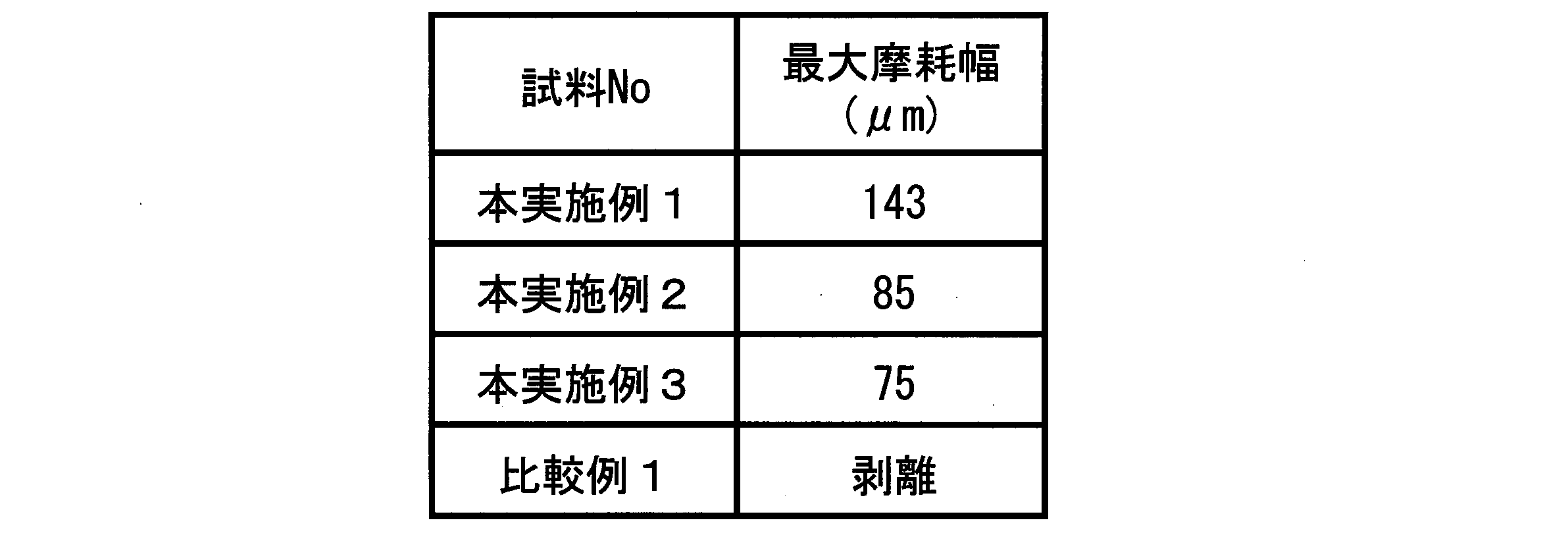
実施例2においても、本実施例1~3は安定した摩耗形態を示した。一方、hcp構造の(102)面が最大強度を示した比較例1は早期に剥離した。特に、本実施例2、3については、本実施例1~3の中でも、金属(半金属を含む)元素と窒素、酸素、炭素、アルゴンの含有比率を100原子とした場合、窒素の含有比率が50原子%以上となっており、本実施例1に比べても最大摩耗幅が大きく低減された。
Also in Example 2, Examples 1 to 3 showed a stable wear form. On the other hand, Comparative Example 1 in which the (102) plane of the hcp structure showed the maximum strength was peeled off early. In particular, in Examples 2 and 3, when the content ratio of the metal (including metalloid) element to nitrogen, oxygen, carbon, and argon is 100 atoms among the Examples 1 to 3, the nitrogen content ratio Is 50 atomic% or more, and the maximum wear width is significantly reduced as compared with the first embodiment.
Claims (3)
- 工具の表面に硬質皮膜を有する被覆切削工具であって、
前記硬質皮膜は窒化物であり、金属(半金属を含む)元素の総量に対して、アルミニウム(Al)を80原子%以上90原子%以下で含有しており、チタン(Ti)を10原子%以上20原子%以下で含有しており、金属元素(半金属を含む)と非金属元素の総量に対して、アルゴン(Ar)を0.50原子%以下で含有しており、
前記硬質皮膜はX線回折で特定される結晶構造が六方最密充填構造であり、かつ、AlN(100)面に起因する回折ピークが最大強度を示し、
平均結晶粒径が5nm以上50nm以下であり、
前記硬質皮膜の断面観察において、円相当径が1.0μm以上のドロップレットが100μm2当たり5個以下であることを特徴とする被覆切削工具。 A coated cutting tool having a hard film on the surface of the tool,
The hard coating is a nitride and contains aluminum (Al) at 80 atomic% or more and 90 atomic% or less, and 10 atomic% of titanium (Ti) based on the total amount of metal (including metalloid) elements. More than 20 at% or less, containing 0.50 at% or less of argon (Ar) with respect to the total amount of metal elements (including semimetals) and non-metal elements
The hard coating has a hexagonal close-packed crystal structure specified by X-ray diffraction, and a diffraction peak attributable to an AlN (100) surface exhibits the maximum intensity.
An average crystal grain size of 5 nm or more and 50 nm or less,
A coated cutting tool characterized in that, in cross-sectional observation of the hard film, the number of droplets having a circle equivalent diameter of 1.0 μm or more is 5 or less per 100 μm 2 . - 前記硬質皮膜は、金属(半金属を含む)元素と窒素、酸素、炭素、アルゴンの含有比率を100原子%とした場合、窒素の含有比率が50原子%以上であることを特徴とする請求項1に記載の被覆切削工具。 The hard coating is characterized in that the content ratio of nitrogen is 50 atomic% or more, when the content ratio of metal (including metalloid) element, nitrogen, oxygen, carbon, and argon is 100 atomic%. The coated cutting tool according to 1.
- 前記硬質皮膜は、被加工材と接触する工具の最表層に設けられていることを特徴とする請求項1または2に記載の被覆切削工具。 The coated hard cutting tool according to claim 1 or 2, wherein the hard coating is provided on the outermost layer of the tool in contact with the workpiece.
Priority Applications (2)
| Application Number | Priority Date | Filing Date | Title |
|---|---|---|---|
| EP17921877.1A EP3670043A4 (en) | 2017-08-15 | 2017-11-30 | Coated cutting tool |
| JP2019536411A JP6844704B2 (en) | 2017-08-15 | 2017-11-30 | Cover cutting tool |
Applications Claiming Priority (2)
| Application Number | Priority Date | Filing Date | Title |
|---|---|---|---|
| JP2017156730 | 2017-08-15 | ||
| JP2017-156730 | 2017-08-15 |
Publications (1)
| Publication Number | Publication Date |
|---|---|
| WO2019035219A1 true WO2019035219A1 (en) | 2019-02-21 |
Family
ID=65362893
Family Applications (1)
| Application Number | Title | Priority Date | Filing Date |
|---|---|---|---|
| PCT/JP2017/043027 WO2019035219A1 (en) | 2017-08-15 | 2017-11-30 | Coated cutting tool |
Country Status (3)
| Country | Link |
|---|---|
| EP (1) | EP3670043A4 (en) |
| JP (1) | JP6844704B2 (en) |
| WO (1) | WO2019035219A1 (en) |
Cited By (2)
| Publication number | Priority date | Publication date | Assignee | Title |
|---|---|---|---|---|
| JP2021112805A (en) * | 2020-01-21 | 2021-08-05 | 株式会社Moldino | Coated cutting tool |
| EP3943222A4 (en) * | 2019-03-22 | 2022-08-03 | MOLDINO Tool Engineering, Ltd. | Coated cutting tool |
Citations (10)
| Publication number | Priority date | Publication date | Assignee | Title |
|---|---|---|---|---|
| JPH08209333A (en) | 1988-03-24 | 1996-08-13 | Kobe Steel Ltd | Wear resistant film coated member |
| JP2005344148A (en) * | 2004-06-01 | 2005-12-15 | Sumitomo Electric Ind Ltd | Wear-resistant film, and surface-coated cutting tool using the same |
| JP2008545063A (en) * | 2005-07-04 | 2008-12-11 | フラウンホーファー−ゲゼルシャフト ツル フェルデルング デル アンゲヴァンテン フォルシュング エー ファウ | Hard film-coated object and method for manufacturing the same |
| JP2011189419A (en) | 2010-03-12 | 2011-09-29 | Hitachi Metals Ltd | Coated tool excellent in wear resistance |
| JP2013202700A (en) | 2012-03-27 | 2013-10-07 | Hitachi Tool Engineering Ltd | Coated tool excellent in durability, and method of manufacturing the same |
| WO2014002948A1 (en) | 2012-06-29 | 2014-01-03 | 住友電工ハードメタル株式会社 | Cutting tool for surface coating |
| WO2014142190A1 (en) * | 2013-03-12 | 2014-09-18 | 日立ツール株式会社 | Hard film, hard film covered member, and method for manufacturing hard film and hard film covered member |
| WO2015186413A1 (en) * | 2014-06-02 | 2015-12-10 | 三菱日立ツール株式会社 | Rigid coating film, member coated with rigid coating film, production processes therefor, and target for use in producing rigid coating film |
| JP2017156730A (en) | 2016-03-04 | 2017-09-07 | 株式会社コシダカホールディングス | Karaoke Baseball Game |
| WO2017170536A1 (en) * | 2016-03-30 | 2017-10-05 | 三菱日立ツール株式会社 | Coated cutting tool |
Family Cites Families (3)
| Publication number | Priority date | Publication date | Assignee | Title |
|---|---|---|---|---|
| JP6206133B2 (en) * | 2012-11-30 | 2017-10-04 | 三菱マテリアル株式会社 | Surface coated cutting tool |
| US9168664B2 (en) * | 2013-08-16 | 2015-10-27 | Kennametal Inc. | Low stress hard coatings and applications thereof |
| US9896767B2 (en) * | 2013-08-16 | 2018-02-20 | Kennametal Inc | Low stress hard coatings and applications thereof |
-
2017
- 2017-11-30 WO PCT/JP2017/043027 patent/WO2019035219A1/en unknown
- 2017-11-30 JP JP2019536411A patent/JP6844704B2/en active Active
- 2017-11-30 EP EP17921877.1A patent/EP3670043A4/en active Pending
Patent Citations (10)
| Publication number | Priority date | Publication date | Assignee | Title |
|---|---|---|---|---|
| JPH08209333A (en) | 1988-03-24 | 1996-08-13 | Kobe Steel Ltd | Wear resistant film coated member |
| JP2005344148A (en) * | 2004-06-01 | 2005-12-15 | Sumitomo Electric Ind Ltd | Wear-resistant film, and surface-coated cutting tool using the same |
| JP2008545063A (en) * | 2005-07-04 | 2008-12-11 | フラウンホーファー−ゲゼルシャフト ツル フェルデルング デル アンゲヴァンテン フォルシュング エー ファウ | Hard film-coated object and method for manufacturing the same |
| JP2011189419A (en) | 2010-03-12 | 2011-09-29 | Hitachi Metals Ltd | Coated tool excellent in wear resistance |
| JP2013202700A (en) | 2012-03-27 | 2013-10-07 | Hitachi Tool Engineering Ltd | Coated tool excellent in durability, and method of manufacturing the same |
| WO2014002948A1 (en) | 2012-06-29 | 2014-01-03 | 住友電工ハードメタル株式会社 | Cutting tool for surface coating |
| WO2014142190A1 (en) * | 2013-03-12 | 2014-09-18 | 日立ツール株式会社 | Hard film, hard film covered member, and method for manufacturing hard film and hard film covered member |
| WO2015186413A1 (en) * | 2014-06-02 | 2015-12-10 | 三菱日立ツール株式会社 | Rigid coating film, member coated with rigid coating film, production processes therefor, and target for use in producing rigid coating film |
| JP2017156730A (en) | 2016-03-04 | 2017-09-07 | 株式会社コシダカホールディングス | Karaoke Baseball Game |
| WO2017170536A1 (en) * | 2016-03-30 | 2017-10-05 | 三菱日立ツール株式会社 | Coated cutting tool |
Non-Patent Citations (1)
| Title |
|---|
| See also references of EP3670043A4 * |
Cited By (3)
| Publication number | Priority date | Publication date | Assignee | Title |
|---|---|---|---|---|
| EP3943222A4 (en) * | 2019-03-22 | 2022-08-03 | MOLDINO Tool Engineering, Ltd. | Coated cutting tool |
| JP2021112805A (en) * | 2020-01-21 | 2021-08-05 | 株式会社Moldino | Coated cutting tool |
| JP7410385B2 (en) | 2020-01-21 | 2024-01-10 | 株式会社Moldino | coated cutting tools |
Also Published As
| Publication number | Publication date |
|---|---|
| EP3670043A4 (en) | 2021-03-24 |
| JP6844704B2 (en) | 2021-03-17 |
| JPWO2019035219A1 (en) | 2020-08-06 |
| EP3670043A1 (en) | 2020-06-24 |
Similar Documents
| Publication | Publication Date | Title |
|---|---|---|
| JP6362003B2 (en) | Coated cutting tool | |
| JP5673904B1 (en) | Coated cutting tool and manufacturing method thereof | |
| JP6844705B2 (en) | Cover cutting tool | |
| JP6658983B2 (en) | Coated cutting tool | |
| WO2022172954A1 (en) | Coated tool | |
| JP2023179643A (en) | Coated tool | |
| JP6844704B2 (en) | Cover cutting tool | |
| WO2022202729A1 (en) | Coated cutting tool | |
| WO2020194899A1 (en) | Coated cutting tool | |
| JP2012139795A (en) | Surface coated cutting tool with hard coating layer exhibiting superior resistance against peeling and chipping in high speed cutting of soft hard-to-cut material | |
| WO2024048304A1 (en) | Coated tool | |
| JP7164828B2 (en) | coated cutting tools | |
| WO2023022230A1 (en) | Coated tool | |
| JP7410385B2 (en) | coated cutting tools | |
| WO2024004873A1 (en) | Coated cutting tool | |
| WO2024048306A1 (en) | Coated tool | |
| JP2024027836A (en) | coated tools | |
| WO2020039735A1 (en) | Cutting tool | |
| WO2020039736A1 (en) | Cutting tool | |
| JP2024047170A (en) | Coated Cutting Tools |
Legal Events
| Date | Code | Title | Description |
|---|---|---|---|
| 121 | Ep: the epo has been informed by wipo that ep was designated in this application |
Ref document number: 17921877 Country of ref document: EP Kind code of ref document: A1 |
|
| ENP | Entry into the national phase |
Ref document number: 2019536411 Country of ref document: JP Kind code of ref document: A |
|
| NENP | Non-entry into the national phase |
Ref country code: DE |
|
| ENP | Entry into the national phase |
Ref document number: 2017921877 Country of ref document: EP Effective date: 20200316 |