WO2019026850A1 - 軸受およびステアリング機構 - Google Patents
軸受およびステアリング機構 Download PDFInfo
- Publication number
- WO2019026850A1 WO2019026850A1 PCT/JP2018/028480 JP2018028480W WO2019026850A1 WO 2019026850 A1 WO2019026850 A1 WO 2019026850A1 JP 2018028480 W JP2018028480 W JP 2018028480W WO 2019026850 A1 WO2019026850 A1 WO 2019026850A1
- Authority
- WO
- WIPO (PCT)
- Prior art keywords
- bush
- main body
- slit
- rack
- bearing
- Prior art date
- Legal status (The legal status is an assumption and is not a legal conclusion. Google has not performed a legal analysis and makes no representation as to the accuracy of the status listed.)
- Ceased
Links
Images


Classifications
-
- B—PERFORMING OPERATIONS; TRANSPORTING
- B62—LAND VEHICLES FOR TRAVELLING OTHERWISE THAN ON RAILS
- B62D—MOTOR VEHICLES; TRAILERS
- B62D3/00—Steering gears
- B62D3/02—Steering gears mechanical
- B62D3/12—Steering gears mechanical of rack-and-pinion type
-
- F—MECHANICAL ENGINEERING; LIGHTING; HEATING; WEAPONS; BLASTING
- F16—ENGINEERING ELEMENTS AND UNITS; GENERAL MEASURES FOR PRODUCING AND MAINTAINING EFFECTIVE FUNCTIONING OF MACHINES OR INSTALLATIONS; THERMAL INSULATION IN GENERAL
- F16C—SHAFTS; FLEXIBLE SHAFTS; ELEMENTS OR CRANKSHAFT MECHANISMS; ROTARY BODIES OTHER THAN GEARING ELEMENTS; BEARINGS
- F16C17/00—Sliding-contact bearings for exclusively rotary movement
- F16C17/02—Sliding-contact bearings for exclusively rotary movement for radial load only
-
- F—MECHANICAL ENGINEERING; LIGHTING; HEATING; WEAPONS; BLASTING
- F16—ENGINEERING ELEMENTS AND UNITS; GENERAL MEASURES FOR PRODUCING AND MAINTAINING EFFECTIVE FUNCTIONING OF MACHINES OR INSTALLATIONS; THERMAL INSULATION IN GENERAL
- F16C—SHAFTS; FLEXIBLE SHAFTS; ELEMENTS OR CRANKSHAFT MECHANISMS; ROTARY BODIES OTHER THAN GEARING ELEMENTS; BEARINGS
- F16C25/00—Bearings for exclusively rotary movement adjustable for wear or play
- F16C25/02—Sliding-contact bearings
- F16C25/04—Sliding-contact bearings self-adjusting
-
- F—MECHANICAL ENGINEERING; LIGHTING; HEATING; WEAPONS; BLASTING
- F16—ENGINEERING ELEMENTS AND UNITS; GENERAL MEASURES FOR PRODUCING AND MAINTAINING EFFECTIVE FUNCTIONING OF MACHINES OR INSTALLATIONS; THERMAL INSULATION IN GENERAL
- F16C—SHAFTS; FLEXIBLE SHAFTS; ELEMENTS OR CRANKSHAFT MECHANISMS; ROTARY BODIES OTHER THAN GEARING ELEMENTS; BEARINGS
- F16C27/00—Elastic or yielding bearings or bearing supports, for exclusively rotary movement
- F16C27/06—Elastic or yielding bearings or bearing supports, for exclusively rotary movement by means of parts of rubber or like materials
Definitions
- the present invention relates to a bearing, and more particularly to a bearing suitable for a rack bush used in a rack and pinion type steering mechanism.
- Patent Document 1 describes a rack bush used for a rack and pinion type steering mechanism.
- the rack bush is accommodated in the cylindrical housing in a state in which axial movement is restricted, and supports the load applied to the rack bar while allowing axial movement of the rack bar,
- the bearing body is made of synthetic resin, and a plurality of circumferentially arranged slits are formed from the end face along the axial direction, and on its outer peripheral surface, a mounting groove for mounting an elastic ring is formed It is done.
- the diameter of the bearing main body is reduced by the elastic ring and the plurality of slits, and the rack bar inserted into the bearing main body is tightened.
- the clearance between the inner peripheral surface of the bearing main body and the outer peripheral surface of the rack bar Can be made zero to prevent the generation of unpleasant noise due to the collision between the inner peripheral surface of the bearing body and the outer peripheral surface of the rack bar.
- the rotational movement of the steering shaft is achieved by the meshing between the pinion gear formed at the tip of the steering shaft and the rack gear formed on the rack bar. Is converted to linear motion of the rack bar.
- the tie rods interlocked with the rack bar apply torque to the steering knuckle through the tie rod ends to rotate the tire around the king pins.
- the reaction force from the tire is input to the rack bar through the steering knuckle, the tie rod end, and the tie rod.
- the rack bush described in Patent Document 1 since the elastic ring attached to the bearing main body is in contact with the inner peripheral surface of the housing and accommodated in the housing, the rack bush described in Patent Document 1 is opposed to the tire input to the rack bar.
- the force causes the elastic ring to be compressively deformed and elastically deformed to escape into the slit of the bush main body.
- the rack bush moves in the housing, and as a result, the time lag from the steering operation to the actual turning of the tire increases, which adversely affects the steering operation feeling.
- the present invention has been made in view of the above-mentioned circumstances, and an object thereof is to provide a bearing suitable for a rack bush which can reduce the influence on the feeling of a steering operation.
- the slits formed inward from the end face are in one area.
- the plurality of slits are deflected in the circumferential direction so as to be arranged only in a certain slit arrangement area and not arranged in the other area, ie, a slit non-arrangement area.
- the ratio of the slit non-arrangement region in the circumferential direction of the bush main body is preferably half or less.
- the bearing of the present invention is Radially telescopic bushing body, An elastic ring mounted on the bush body,
- the bush body is It has a plurality of slits formed inward from the end face, The plurality of slits are When the bush main body is divided into two areas in the circumferential direction, it is arranged only in the slit arrangement area which is one area, and not in the slit non-arrangement area which is the other area. It is arranged biased.
- the steering mechanism of the present invention is It is a rack and pinion type steering mechanism,
- the bearing that supports the load applied to the rack bar while allowing axial movement of the rack bar;
- a cylindrical housing that accommodates the bearing while constraining axial movement of the bearing.
- the bearing is A reaction force supporting member, which is an inner peripheral surface of the housing facing the input direction of the reaction force input from the tire to the rack bar through a tie rod connected to the rack bar, the slit non-arrangement area of the bush main body It is housed within the housing so as to face the surface.
- the slits are arranged only in the slit arrangement area which is one area, and not arranged in the slit non-arrangement area which is the other area.
- the plurality of slits are deflected in the circumferential direction, and the slit non-arranged area generates the largest reaction force on the inner circumferential surface of the housing which receives the reaction force input from the tire to the rack bar through the tie rods.
- the elastic ring By mounting the rack bush to the housing so as to face the reaction force supporting surface which is a region including the portion to be bent, the elastic ring is elastically deformed against the reaction force of the tire on the reaction force supporting surface side, and the inside of the slit In this way, the rigidity against the reaction force of the tire can be improved, and the movement of the rack bar within the housing due to the reaction force of the tire can be suppressed. For this reason, the time lag from the steering operation to the actual turning of the tire is reduced. Further, in order to improve the rigidity of the tire against the reaction force, the inner diameter of the elastic ring does not need to be reduced to strengthen the tightening of the rack bar, which does not affect the sliding characteristics of the rack bush. Therefore, according to the present invention, it is possible to provide a bearing suitable for a rack bush which can reduce the influence on the feeling of steering operation.
- FIG. 1 is a partial cross-sectional view of a portion of a rack and pinion type steering mechanism according to an embodiment of the present invention.
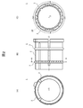
- 2 (A) and 2 (B) are a front view and a side view of the rack bush 1
- FIG. 2 (C) is a cross-sectional view of the rack bush 1 taken along line AA of FIG. 2 (B).
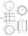
- . 3 (A), 3 (B) and 3 (C) are a front view, a side view and a rear view of the bush main body 2
- FIG. 3 (D) is a bush main body shown in FIG. 3 (A).
- FIG. 3 (E) is a cross-sectional view of the bush main body 2 taken along the line CC shown in FIG. 3 (B).
- FIGS. 4A and 4B are a front view and a side view of the elastic ring 3
- FIG. 4C is a cross-sectional view of the elastic ring 3 shown in FIG. .
- FIG. 1 is a partial cross-sectional view of a part of a rack and pinion type steering mechanism according to the present embodiment.
- the rack and pinion type steering mechanism supports the load applied to the rack bar 5 while allowing the movement of the rack bar 5 in the axial center O direction, and the rack bush 1
- the cylindrical housing 4 which accommodates the rack bush 1 is provided, restraining the movement of the axial center O direction of the bush 1.
- FIG. 2 (A) and 2 (B) are a front view and a side view of the rack bush 1
- FIG. 2 (C) is a cross-sectional view of the rack bush 1 taken along line AA of FIG. 2 (B). .
- the rack bush 1 includes a bush main body 2 into which the rack bar 5 is inserted, and an elastic ring 3 attached to the bush main body 2.
- an elastic ring 3 attached to the bush main body 2.
- one or three or more elastic rings 3 may be attached to the bush main body 2 .
- FIG. 3 (A), 3 (B) and 3 (C) are a front view, a side view and a rear view of the bush main body 2, and FIG. 3 (D) is a bush main body shown in FIG. 3 (A).
- FIG. 3 (E) is a cross-sectional view of the bush main body 2 taken along the line CC shown in FIG. 3 (B).
- the bush main body 2 is formed of a synthetic resin having good sliding characteristics, such as polyacetal resin, polyamide resin, polyethylene resin, etc., and is a cylindrical member which can expand and contract in the radial direction, and is formed on the inner circumferential surface 20 as illustrated.
- a sliding surface 21 in sliding contact with the outer peripheral surface 50 of the inserted rack bar 5, and a plurality of first slits 25 formed along the axis O direction from one end face 23 to the other end face 24;
- a plurality of second slits 26 formed along the axial center O direction from the other end face 24 to one end face 23, an engagement convex portion 27 formed on the outer peripheral surface 22, and a circumference on the outer peripheral surface 22
- a mounting groove 28 formed in the direction for mounting the elastic ring 3.
- the first slit 25 and the second slit 26 are for deforming the bush main body 2 in the diameter reducing direction, and the bush main body 2 is divided into two semi-cylindrical portions by a virtual plane P including the axial center O In this case, they are alternately arranged at equal intervals in the circumferential direction while being deflected toward one half cylindrical portion.
- a slit disposition area 280 which is a semi-cylindrical portion in which the first slit 25 and the second slit 26 are disposed, and a semi-cylindrical portion in which the first slit 25 and the second slit 26 are not disposed.
- the slit non-arranged area 281 which is
- the engagement convex portion 27 protrudes radially outward from the outer peripheral surface 22 on one end surface 23 side, and an engagement concave portion (not shown) formed to cut off the inner peripheral surface 40 on one end surface 41 of the housing 4 Housed in As a result, the rotation of the rack bush 1 housed in the housing 4 about the axis O is restricted. Further, the ring-shaped lid 6 is attached to the one end surface 41 of the housing 4 in a state in which the engagement convex portion 27 is accommodated in the engagement concave portion of the housing 4. Thereby, the movement of the rack bush 1 accommodated in the housing 4 in the direction of the axis O is restricted (see FIG. 1).
- FIGS. 4A and 4B are a front view and a side view of the elastic ring 3
- FIG. 4C is a cross-sectional view of the elastic ring 3 shown in FIG. .
- the elastic ring 3 is an annular member formed of an elastic body such as a synthetic rubber or a thermoplastic elastomer, and has an inner diameter Ri smaller than the diameter Ra (see FIG. 3) of the groove bottom 29 of the mounting groove 28 of the bush main body 2
- the outer diameter Re is larger than the inner diameter Rj (see FIG. 1) of the housing 4.
- the elastic ring 3 biases the bush main body 2 in the diameter reducing direction by mounting in the mounting groove 28 of the bush main body 2. And tighten the rack bar 5 inserted into the bush body 2. Further, since the outer diameter Re of the elastic ring 3 is larger than the inner diameter Rj of the housing 4, when the rack bush 1 is accommodated in the housing 4, the elastic ring 3 is in pressure contact with the inner circumferential surface 40 of the housing 4 and is compressed and deformed. Thereby, the rack bush 1 is fitted with the housing 4.
- the inner circumferential surface 40 of the housing 4 (housing opposed to the input direction of the reaction force N input to the rack bar 5 from a tire (not shown) via a tie rod (not shown) connected to the rack bar 5)
- the rack bush 1 having the above-described configuration is configured such that, of the inner circumferential surfaces 40 of No. 4 as a reaction force supporting surface 42, a region including a portion that generates a maximum reaction force with respect to the reaction force N input to the rack bar 5. And positioning by engagement between the engagement convex portion 27 of the bush main body 2 and the engagement concave portion (not shown) of the housing 4 so that the slit non-arranged area 281 of the bush main body 2 faces the reaction force supporting surface 42 There is.
- the rack bush 1 does not have the slit arrangement region 280 where the first slit 25 and the second slit 26 are arranged, and the first slit 25 and the second slit 26 not arranged in the bush main body 2.
- a slit non-arranged area 281 is provided, and the rack bush 1 is accommodated in the housing 4 such that the slit non-arranged area 281 faces the reaction force supporting surface 42 of the housing 4.
- the elastic ring 3 elastically deforms against the reaction force input from the tire to the rack bar 5 via the tie rod, and the inside of the first slit 25 and the second slit 26. Since it is possible to avoid escape to the above, the rigidity against the reaction force of the tire is improved, and the movement of the rack bar 5 in the housing 4 due to the reaction force of the tire can be suppressed. For this reason, the time lag from the steering operation to the actual turning of the tire is reduced.
- the rack bush 1 capable of reducing the influence on the feeling of the steering operation.
- the first slit 25 is deflected to one semi-cylindrical portion side.
- the slit arrangement region 280 and the slit non-arrangement region 281 are substantially equally divided in the circumferential direction.
- the ratio of the slit arrangement area 280 and the slit non-arrangement area 281 may not be approximately equally divided in the circumferential direction of the bush main body 2.
- the ratio of the slit non-arranged area 281 in the circumferential direction of the bush main body 2 is preferably half or less.
- the plurality of first slits 25 formed along the axial center O direction from the one end face 23 toward the other end face 24 in the slit arrangement region 280 of the bush main body 2 and the other A plurality of second slits 26 are formed along the axial center O direction from the end face 24 of the first end face 23 to the one end face 23.
- the present invention is not limited to this. Only one of the first slit 25 and the second slit 26 may be provided in the slit arrangement region 280 of the bush main body 2.
- the shape of the bush main body 2 is made cylindrical, it should just be a cylindrical shape which adapts the shape of the rack bar 5 inserted.
- the rack bush used for the rack and pinion type steering mechanism has been described as an example, but the present invention is not limited to this.
- the present invention can be widely applied to a bearing that supports the load of an inserted shaft member.
Landscapes
- Engineering & Computer Science (AREA)
- General Engineering & Computer Science (AREA)
- Mechanical Engineering (AREA)
- Chemical & Material Sciences (AREA)
- Combustion & Propulsion (AREA)
- Transportation (AREA)
- Sliding-Contact Bearings (AREA)
- Support Of The Bearing (AREA)
Abstract
ステアリング操作のフィーリングに与える影響を低減することができるラックブッシュに好適な軸受を提供する。ラックブッシュ(1)は、円筒状のハウジング(4)内に収容され、ラックバー(5)の軸心O方向の移動を許容しつつ、ラックバー(5)に加わる荷重を支持するものであり、径方向に伸縮自在なブッシュ本体(2)と、ブッシュ本体(2)に装着された弾性リング(3)と、を備えている。ブッシュ本体(2)は、端面(23、24)から軸心O方向に沿って形成された複数の第一、第二スリット(25、26)を有する。第一、第二スリット25、26は、ブッシュ本体2の円周方向に偏向配置されて、ブッシュ本体(2)に、第一、第二スリット(25、26)が配置されているスリット配置領域(280)と、第一、第二スリット(25、26)が配置されていないスリット無配置領域(281)と、を形成している。
Description
本発明は、軸受に関し、特に、ラックアンドピニオン式のステアリング機構に用いられるラックブッシュに好適な軸受に関する。
特許文献1には、ラックアンドピニオン式のステアリング機構に用いられるラックブッシュが記載されている。このラックブッシュは、円筒状のハウジング内に軸心方向の移動が規制された状態で収容され、ラックバーの軸心方向の移動を許容しつつ、ラックバーに加わる荷重を支持するものであり、ラックバーが挿入される円筒状の軸受本体と、軸受本体に装着され、軸受本体を径方向内方に付勢する弾性リングと、を備えている。軸受本体は合成樹脂製であり、円周方向に配置された複数のスリットが端面から軸心方向に沿って形成されており、その外周面には、弾性リングを装着するための装着溝が形成されている。
このラックブッシュによれば、弾性リングおよび複数のスリットによって軸受本体が縮径し、軸受本体に挿入されたラックバーを締め付けるので、軸受本体の内周面とラックバーの外周面との間のクリアランスをゼロにして、軸受本体の内周面とラックバーの外周面との衝突による不快音の発生を防止することができる。また、ラックバーの外径寸法誤差による摩擦トルクの変動を防止することができる。
ところで、ラックアンドピニオン式のステアリング機構において、ステアリング操作によりステアリングシャフトが回転すると、このステアリングシャフトの先端に形成されたピニオンギアと、ラックバーに形成されたラックギアとの噛み合いにより、ステアリングシャフトの回転運動がラックバーの直線運動に変換される。これにより、ラックバーと連動するタイロッドがタイロッドエンドを介してステアリングナックルに、タイヤをキングピン周りに回転させるトルクを付与する。この際、タイヤからの反力がステアリングナックル、タイロッドエンド、およびタイロッドを介してラックバーに入力する。
ここで、特許文献1に記載のラックブッシュは、軸受本体に装着された弾性リングがハウジングの内周面と当接してハウジング内に収容されているため、ラックバーに入力されたタイヤからの反力により、弾性リングが圧縮変形するとともに、弾性変形してブッシュ本体のスリット内に逃げる。これにより、ラックブッシュがハウジング内を移動してしまい、その結果、ステアリング操作がなされてから実際にタイヤが向きを変えるまでのタイムラグが大きくなり、これがステアリング操作のフィーリングに悪影響を与えている。
本発明は、上記事情に鑑みてなされたものであり、その目的は、ステアリング操作のフィーリングに与える影響を低減することができるラックブッシュに好適な軸受を提供することにある。
上記課題を解決するために、本発明では、ラックバーが挿入されるブッシュ本体を円周方向に二つの領域に分けた場合に、端面から内方に向けて形成されたスリットが一方の領域であるスリット配置領域にのみ配置され、他方の領域であるスリット無配置領域には配置されないように、複数のスリットを円周方向に偏向配置している。ここで、スリット無配置領域のブッシュ本体の円周方向に占める割合は、半分以下であることが好ましい。
例えば、本発明の軸受は、
径方向に伸縮自在なブッシュ本体と、
前記ブッシュ本体に装着された弾性リングと、を備え、
前記ブッシュ本体は、
端面から内方に向けて形成された複数のスリットを有し、
前記複数のスリットは、
前記ブッシュ本体を円周方向に二つの領域に分けた場合に、一方の領域であるスリット配置領域にのみ配置され、他方の領域であるスリット無配置領域には配置されないように、円周方向に偏向配置されている。
径方向に伸縮自在なブッシュ本体と、
前記ブッシュ本体に装着された弾性リングと、を備え、
前記ブッシュ本体は、
端面から内方に向けて形成された複数のスリットを有し、
前記複数のスリットは、
前記ブッシュ本体を円周方向に二つの領域に分けた場合に、一方の領域であるスリット配置領域にのみ配置され、他方の領域であるスリット無配置領域には配置されないように、円周方向に偏向配置されている。
また、本発明のステアリング機構は、
ラックアンドピニオン式のステアリング機構であって、
ラックバーの軸心方向の移動を許容しつつ、ラックバーに加わる荷重を支持する前記軸受と、
前記軸受の軸心方向の移動を拘束しつつ、当該軸受を収容する円筒状のハウジングと、を備え、
前記軸受は、
前記ブッシュ本体の前記スリット無配置領域が、前記ラックバーに連結されたタイロッドを介してタイヤから前記ラックバーに入力される反力の入力方向と対向する前記ハウジングの内周面である反力支持面と対面するように、前記ハウジング内に収容されている。
ラックアンドピニオン式のステアリング機構であって、
ラックバーの軸心方向の移動を許容しつつ、ラックバーに加わる荷重を支持する前記軸受と、
前記軸受の軸心方向の移動を拘束しつつ、当該軸受を収容する円筒状のハウジングと、を備え、
前記軸受は、
前記ブッシュ本体の前記スリット無配置領域が、前記ラックバーに連結されたタイロッドを介してタイヤから前記ラックバーに入力される反力の入力方向と対向する前記ハウジングの内周面である反力支持面と対面するように、前記ハウジング内に収容されている。
本発明では、ブッシュ本体を円周方向に二つの領域に分けた場合に、スリットが一方の領域であるスリット配置領域にのみ配置され、他方の領域であるスリット無配置領域には配置されないように、複数のスリットを円周方向に偏向配置しており、スリット無配置領域が、タイロッドを介してタイヤからラックバーに入力される反力を受けるハウジングの内周面のうち最大の反力が発生する部位を含む領域である反力支持面と対向するように、ラックブッシュをハウジングに装着することにより、反力支持面側において、タイヤの反力に対して弾性リングが弾性変形してスリット内に逃げるのを回避でき、これにより、タイヤの反力に対する剛性が向上し、タイヤの反力よるラックバーのハウジング内の移動を抑制することができる。このため、ステアリング操作がなされてから実際にタイヤが向きを変えるまでのタイムラグが小さくなる。また、本発明では、タイヤの反力に対する剛性を向上させるために、弾性リングの内径を小さくして、ラックバーの締め付けを強くする必要がないので、ラックブッシュの摺動特性に影響しない。したがって、本発明によれば、ステアリング操作のフィーリングに与える影響を低減することができるラックブッシュに好適な軸受を提供することができる。
以下、本発明の一実施の形態について、図面を参照して説明する。
図1は、本実施の形態に係るラックアンドピニオン式のステアリング機構の一部の部分断面図である。
図示するように、本実施の形態に係るラックアンドピニオン式のステアリング機構は、ラックバー5の軸心O方向の移動を許容しつつ、ラックバー5に加わる荷重を支持するラックブッシュ1と、ラックブッシュ1の軸心O方向の移動を拘束しつつ、ラックブッシュ1を収容する円筒状のハウジング4と、を備えている。
図2(A)および図2(B)は、ラックブッシュ1の正面図および側面図であり、図2(C)は、図2(B)に示すラックブッシュ1のA-A断面図である。
図示するように、ラックブッシュ1は、ラックバー5が挿入されるブッシュ本体2と、ブッシュ本体2に装着された弾性リング3と、を備えている。本実施の形態では、2個の弾性リング3がブッシュ本体2に装着されている場合を例示しているが、1個または3個以上の弾性リング3がブッシュ本体2に装着されていてもよい。
図3(A)、図3(B)および図3(C)は、ブッシュ本体2の正面図、側面図および背面図であり、図3(D)は、図3(A)に示すブッシュ本体2のB-B断面図であり、図3(E)は、図3(B)に示すブッシュ本体2のC-C断面図である。
ブッシュ本体2は、ポリアセタール樹脂、ポリアミド樹脂、ポリエチレン樹脂等の摺動特性のよい合成樹脂で形成され、径方向に伸縮自在な円筒状部材であり、図示するように、内周面20に形成され、挿入されたラックバー5の外周面50と摺接する摺動面21と、一方の端面23から他方の端面24に向けて軸心O方向に沿って形成された複数の第一スリット25と、他方の端面24から一方の端面23に向けて軸心O方向に沿って形成された複数の第二スリット26と、外周面22に形成された係合凸部27と、外周面22に円周方向に形成され、弾性リング3を装着するための装着溝28と、を備えている。
第一スリット25および第二スリット26は、ブッシュ本体2を縮径方向に変形するためのものであり、軸心Oを含む仮想的な平面Pによってブッシュ本体2を二つの半円筒部に分割した場合に、一方の半円筒部側に偏向して、円周方向に等間隔で交互に配置される。これにより、ブッシュ本体2には、第一スリット25および第二スリット26が配置された半円筒部であるスリット配置領域280と、第一スリット25および第二スリット26が配置されていない半円筒部であるスリット無配置領域281と、が形成される。
係合凸部27は、一方の端面23側において外周面22から径方向外方に突出し、ハウジング4の一方の端面41において、内周面40を切り取るように形成された係合凹部(不図示)に収容される。これにより、ハウジング4内に収容されたラックブッシュ1の軸心O周りの回転が拘束される。また、係合凸部27がハウジング4の係合凹部に収容された状態で、ハウジング4の一方の端面41にリング状の蓋6が取り付けられる。これにより、ハウジング4内に収容されたラックブッシュ1の軸心O方向の移動が拘束される(図1参照)。
図4(A)および図4(B)は、弾性リング3の正面図および側面図であり、図4(C)は、図4(A)に示す弾性リング3のD-D断面図である。
弾性リング3は、合成ゴム、熱可塑性エラストマー等の弾性体で形成された円環状部材であり、ブッシュ本体2の装着溝28の溝底29の直径Ra(図3参照)より小さな内径Riと、ハウジング4の内径Rj(図1参照)より大きな外径Reと、を有する。
弾性リング3は、内径Riがブッシュ本体2の装着溝28の溝底29の直径Raより小さいので、ブッシュ本体2の装着溝28に装着することにより、ブッシュ本体2を縮径方向に付勢して、ブッシュ本体2に挿入されたラックバー5を締め付ける。また、弾性リング3は、外径Reがハウジング4の内径Rjより大きいので、ラックブッシュ1をハウジング4に収容した場合に、ハウジング4の内周面40と圧接し圧縮変形する。これにより、ラックブッシュ1がハウジング4と嵌合する。
図1において、ラックバー5に連結されたタイロッド(不図示)を介してタイヤ(不図示)からラックバー5に入力される反力Nの入力方向と対向するハウジング4の内周面40(ハウジング4の内周面40のうちラックバー5に入力される反力Nに対して最大の反力を発生させる部位を含む領域)を反力支持面42とした場合、上記構成のラックブッシュ1は、ブッシュ本体2のスリット無配置領域281が反力支持面42と対面するように、ブッシュ本体2の係合凸部27とハウジング4の係合凹部(不図示)との係合により位置決めされている。
以上、本発明の一実施の形態について説明した。
本実施の形態において、ラックブッシュ1は、ブッシュ本体2に、第一スリット25および第二スリット26が配置されているスリット配置領域280と、第一スリット25および第二スリット26が配置されていないスリット無配置領域281と、を設けており、スリット無配置領域281が、ハウジング4の反力支持面42と対面するように、ラックブッシュ1をハウジング4に収容している。
このため、ハウジング4の反力支持面42側において、タイロッドを介してタイヤからラックバー5に入力される反力に対して弾性リング3が弾性変形し、第一スリット25、第二スリット26内に逃げるのを回避できるので、タイヤの反力に対する剛性が向上し、タイヤの反力よるラックバー5のハウジング4内の移動を抑制することができる。このため、ステアリング操作がなされてから実際にタイヤが向きを変えるまでのタイムラグが小さくなる。
また、ハウジング4の反力支持面42側における剛性を向上させるために、弾性リング3の内径Riを小さくして、ラックバー5の締め付けを強くする必要がないので、ラックブッシュ1の摺動特性に影響しない。
したがって、本実施の形態によれば、ステアリング操作のフィーリングに与える影響を低減することができるラックブッシュ1を提供することができる。
なお、本発明は、上記の実施の形態に限定されるものではなく、その要旨の範囲内で数々の変形は可能である。
例えば、上記の実施の形態では、軸心Oを含む仮想的な平面Pによってブッシュ本体2を二つの半円筒部に分割した場合に、一方の半円筒部側に偏向して、第一スリット25および第二スリット26を配置することにより、スリット配置領域280およびスリット無配置領域281を円周方向に略等分としている。しかし、スリット配置領域280およびスリット無配置領域281の割合は、ブッシュ本体2の円周方向に略等分でなくてもよい。ただし、スリット無配置領域281のブッシュ本体2の円周方向に占める割合が大きくなると、ブッシュ本体2の径方向の伸縮が困難となる。このため、スリット無配置領域281のブッシュ本体2の円周方向に占める割合は、半分以下であることが好ましい。
また、上記の実施の形態では、ブッシュ本体2のスリット配置領域280に、一方の端面23から他方の端面24に向けて軸心O方向に沿って形成された複数の第一スリット25と、他方の端面24から一方の端面23に向けて軸心O方向に沿って形成された複数の第二スリット26と、を設けている。しかし、本発明はこれに限定されない。ブッシュ本体2のスリット配置領域280に、第一スリット25および第二スリット26のいずれか一方のみを設けてもよい。また、上記の実施の形態では、ブッシュ本体2の形状を円筒状としているが、挿入されるラックバー5の形状に適合する筒形状であればよい。
また、上記の実施の形態では、ラックアンドピニオン式のステアリング機構に用いられるラックブッシュを例に取り説明したが、本発明はこれに限定されない。本発明は、挿入さた軸部材の荷重を支持する軸受に広く適用できる。
1:ラックブッシュ、 2:ブッシュ本体、 3:弾性リング、 4:ハウジング、 5:ラックバー、 6:蓋、 20:ブッシュ本体2の内周面、 21:ブッシュ本体2の摺動面、 22:ブッシュ本体2の外周面、 23、24:ブッシュ本体2の端面、 25:第一スリット、 26:第二スリット、 27:係合部、 28:装着溝、 29:装着溝28の溝底、 40:ハウジング4の内周面、 41:ハウジング4の端面、 42:ハウジング4の反力支持面、 280:ブッシュ本体2のスリット配置領域、 281:ブッシュ本体2のスリット無配置領域
Claims (4)
- 径方向に伸縮自在なブッシュ本体と、
前記ブッシュ本体に装着された弾性リングと、を備え、
前記ブッシュ本体は、
端面から内方に向けて形成された複数のスリットを有し、
前記複数のスリットは、
前記ブッシュ本体を円周方向に二つの領域に分けた場合に、一方の領域であるスリット配置領域にのみ配置され、他方の領域であるスリット無配置領域には配置されないように、円周方向に偏向配置されている
ことを特徴とする軸受。 - 請求項1に記載の軸受であって、
前記スリット無配置領域の前記ブッシュ本体の円周方向に占める割合は半分以下である
ことを特徴とする軸受。 - 請求項1または2に記載の軸受であって、
前記複数のスリットは、
一方の端面から他方の端面に向けて形成された第一のスリットと、
他方の端面から一方の端面に向けて形成された第二のスリットと、を有する
ことを特徴とする軸受。 - ラックアンドピニオン式のステアリング機構であって、
ラックバーの軸心方向の移動を許容しつつ、ラックバーに加わる荷重を支持する請求項1ないし3のいずれか一項に記載の軸受と、
前記軸受の軸心方向の移動を拘束しつつ、当該軸受を収容する円筒状のハウジングと、を備え、
前記軸受は、
前記ブッシュ本体の前記スリット無配置領域が、前記ラックバーに連結されたタイロッドを介してタイヤから前記ラックバーに入力される反力の入力方向と対向する前記ハウジングの内周面である反力支持面と対面するように、前記ハウジング内に収容されている
ことを特徴とするステアリング機構。
Priority Applications (1)
| Application Number | Priority Date | Filing Date | Title |
|---|---|---|---|
| CN201880045826.6A CN110869625A (zh) | 2017-08-02 | 2018-07-30 | 支承件和转向机构 |
Applications Claiming Priority (2)
| Application Number | Priority Date | Filing Date | Title |
|---|---|---|---|
| JP2017150197A JP2019027559A (ja) | 2017-08-02 | 2017-08-02 | 軸受およびステアリング機構 |
| JP2017-150197 | 2017-08-02 |
Publications (1)
| Publication Number | Publication Date |
|---|---|
| WO2019026850A1 true WO2019026850A1 (ja) | 2019-02-07 |
Family
ID=65232533
Family Applications (1)
| Application Number | Title | Priority Date | Filing Date |
|---|---|---|---|
| PCT/JP2018/028480 Ceased WO2019026850A1 (ja) | 2017-08-02 | 2018-07-30 | 軸受およびステアリング機構 |
Country Status (3)
| Country | Link |
|---|---|
| JP (1) | JP2019027559A (ja) |
| CN (1) | CN110869625A (ja) |
| WO (1) | WO2019026850A1 (ja) |
Cited By (1)
| Publication number | Priority date | Publication date | Assignee | Title |
|---|---|---|---|---|
| US11548546B2 (en) * | 2017-08-03 | 2023-01-10 | Oiles Corporation | Bearing and steering mechanism |
Citations (3)
| Publication number | Priority date | Publication date | Assignee | Title |
|---|---|---|---|---|
| JP2004331000A (ja) * | 2003-05-12 | 2004-11-25 | Nsk Ltd | ラック軸支持装置及びラックアンドピニオン式ステアリング装置 |
| JP2013067317A (ja) * | 2011-09-26 | 2013-04-18 | Honda Motor Co Ltd | ラックアンドピニオン式ステアリングギヤ |
| JP2015020661A (ja) * | 2013-07-22 | 2015-02-02 | 株式会社ジェイテクト | ラックブッシュ |
Family Cites Families (5)
| Publication number | Priority date | Publication date | Assignee | Title |
|---|---|---|---|---|
| JP4701873B2 (ja) * | 2005-06-28 | 2011-06-15 | オイレス工業株式会社 | ブッシュ軸受及びそれを用いた自動車のラック−ピニオン式操舵装置 |
| JP4899374B2 (ja) * | 2005-08-03 | 2012-03-21 | オイレス工業株式会社 | 軸受装置及びこれに用いられる滑り軸受 |
| JP5167754B2 (ja) * | 2007-10-18 | 2013-03-21 | オイレス工業株式会社 | ブッシュ軸受 |
| JP5141339B2 (ja) * | 2008-03-31 | 2013-02-13 | オイレス工業株式会社 | ブッシュ軸受及びそれを用いた自動車のラック−ピニオン式操舵装置 |
| JP6034812B2 (ja) * | 2014-01-23 | 2016-11-30 | 株式会社ショーワ | ブッシュ軸受の構造 |
-
2017
- 2017-08-02 JP JP2017150197A patent/JP2019027559A/ja active Pending
-
2018
- 2018-07-30 WO PCT/JP2018/028480 patent/WO2019026850A1/ja not_active Ceased
- 2018-07-30 CN CN201880045826.6A patent/CN110869625A/zh active Pending
Patent Citations (3)
| Publication number | Priority date | Publication date | Assignee | Title |
|---|---|---|---|---|
| JP2004331000A (ja) * | 2003-05-12 | 2004-11-25 | Nsk Ltd | ラック軸支持装置及びラックアンドピニオン式ステアリング装置 |
| JP2013067317A (ja) * | 2011-09-26 | 2013-04-18 | Honda Motor Co Ltd | ラックアンドピニオン式ステアリングギヤ |
| JP2015020661A (ja) * | 2013-07-22 | 2015-02-02 | 株式会社ジェイテクト | ラックブッシュ |
Cited By (1)
| Publication number | Priority date | Publication date | Assignee | Title |
|---|---|---|---|---|
| US11548546B2 (en) * | 2017-08-03 | 2023-01-10 | Oiles Corporation | Bearing and steering mechanism |
Also Published As
| Publication number | Publication date |
|---|---|
| JP2019027559A (ja) | 2019-02-21 |
| CN110869625A (zh) | 2020-03-06 |
Similar Documents
| Publication | Publication Date | Title |
|---|---|---|
| WO2019026928A1 (ja) | 軸受およびステアリング機構 | |
| JP6934801B2 (ja) | ラックブッシュおよびステアリング機構 | |
| JP4657590B2 (ja) | 滑り軸受及びそれを具備した軸受機構 | |
| EP2202129B1 (en) | Bearing mechanism with slide bearing | |
| US10259488B2 (en) | Steering system | |
| EP1548339A1 (en) | Dust cover for steering shaft | |
| KR101767614B1 (ko) | 합성 수지제의 미끄럼 베어링 | |
| JP7156379B2 (ja) | ラックアンドピニオン式ステアリングギヤユニット | |
| US11873031B2 (en) | Rack and pinion steering gear unit | |
| JP6572624B2 (ja) | 滑り軸受及びそれを具備した軸受機構 | |
| WO2019026850A1 (ja) | 軸受およびステアリング機構 | |
| JP4899374B2 (ja) | 軸受装置及びこれに用いられる滑り軸受 | |
| JP2019199089A (ja) | ステアリング装置 | |
| US20210293273A1 (en) | Rotational bearing arrangement for a steering column of a motor vehicle | |
| JP2017007428A (ja) | ラックアンドピニオン式ステアリング装置 | |
| JP4773233B2 (ja) | 自在継手 | |
| JP5429405B2 (ja) | ステアリング装置 | |
| JP2019019952A (ja) | 滑り軸受 | |
| JPS59231259A (ja) | ガタつきを防止したスクリユ−シヤフトとナツトの構造 |
Legal Events
| Date | Code | Title | Description |
|---|---|---|---|
| 121 | Ep: the epo has been informed by wipo that ep was designated in this application |
Ref document number: 18841008 Country of ref document: EP Kind code of ref document: A1 |
|
| NENP | Non-entry into the national phase |
Ref country code: DE |
|
| 122 | Ep: pct application non-entry in european phase |
Ref document number: 18841008 Country of ref document: EP Kind code of ref document: A1 |