WO2019026587A1 - 監視システム - Google Patents
監視システム Download PDFInfo
- Publication number
- WO2019026587A1 WO2019026587A1 PCT/JP2018/026371 JP2018026371W WO2019026587A1 WO 2019026587 A1 WO2019026587 A1 WO 2019026587A1 JP 2018026371 W JP2018026371 W JP 2018026371W WO 2019026587 A1 WO2019026587 A1 WO 2019026587A1
- Authority
- WO
- WIPO (PCT)
- Prior art keywords
- refrigerant
- detected
- detection unit
- predetermined period
- detection value
- Prior art date
- Legal status (The legal status is an assumption and is not a legal conclusion. Google has not performed a legal analysis and makes no representation as to the accuracy of the status listed.)
- Ceased
Links
Images



Classifications
-
- F—MECHANICAL ENGINEERING; LIGHTING; HEATING; WEAPONS; BLASTING
- F25—REFRIGERATION OR COOLING; COMBINED HEATING AND REFRIGERATION SYSTEMS; HEAT PUMP SYSTEMS; MANUFACTURE OR STORAGE OF ICE; LIQUEFACTION SOLIDIFICATION OF GASES
- F25B—REFRIGERATION MACHINES, PLANTS OR SYSTEMS; COMBINED HEATING AND REFRIGERATION SYSTEMS; HEAT PUMP SYSTEMS
- F25B1/00—Compression machines, plants or systems with non-reversible cycle
-
- F—MECHANICAL ENGINEERING; LIGHTING; HEATING; WEAPONS; BLASTING
- F25—REFRIGERATION OR COOLING; COMBINED HEATING AND REFRIGERATION SYSTEMS; HEAT PUMP SYSTEMS; MANUFACTURE OR STORAGE OF ICE; LIQUEFACTION SOLIDIFICATION OF GASES
- F25B—REFRIGERATION MACHINES, PLANTS OR SYSTEMS; COMBINED HEATING AND REFRIGERATION SYSTEMS; HEAT PUMP SYSTEMS
- F25B49/00—Arrangement or mounting of control or safety devices
- F25B49/02—Arrangement or mounting of control or safety devices for compression type machines, plants or systems
Definitions
- the present disclosure relates to a monitoring system that monitors a refrigeration cycle apparatus mounted on a mobile unit.
- BACKGROUND Conventionally, a monitoring system that monitors the amount of refrigerant circulating in a refrigeration cycle apparatus is known.
- Patent Document 1 detects whether the amount of refrigerant circulating in the refrigeration cycle apparatus is appropriate or not by detecting the level of the liquid level of the refrigerant stored in the receiver provided in the circuit of the refrigeration cycle apparatus. It is to judge.
- the refrigeration cycle apparatus mounted on the moving body is used in an environment where the moving body and the compressor are accompanied by different vibrations because there are many disturbances such as changes in the outside air temperature and changes in the wind speed. Therefore, in this refrigeration cycle apparatus, a rubber hose is used for a part of the piping of the refrigeration cycle apparatus to absorb the load. Therefore, in the refrigeration cycle apparatus, a so-called slow leak in which the refrigerant leaks minutely through the rubber hose is generated. Therefore, in this refrigeration cycle apparatus, the amount of refrigerant leakage which has no problem within the service life of the product or the maintenance period is calculated on the design and filled in the circuit.
- Patent Document 1 in the refrigeration cycle apparatus mounted on the moving body, the technique of Patent Document 1 is premised on a stationary type in which the height of the liquid surface refrigerant stored in the receiver is detected to determine the appropriateness of the refrigerant amount. Can not be adapted as it is.
- a refrigeration cycle apparatus mounted on a moving body when a large amount of refrigerant leaks from a design leakage amount filled in a circuit, it is important to detect the refrigerant leakage as early as possible. If the detection of the refrigerant leak is delayed, the air conditioning function is degraded, and furthermore, there is a possibility that a failure may occur in a compressor or the like constituting the refrigeration cycle apparatus.
- An object of the present disclosure is to provide a monitoring system capable of early and accurately determining an abnormality of a refrigeration cycle apparatus mounted on a mobile unit.
- a monitoring system for monitoring a refrigeration cycle apparatus in which a compressor, a condenser, an expansion valve and an evaporator are connected by piping and mounted on a moving body,
- a high pressure side pressure detection unit for detecting the pressure of refrigerant flowing in a high pressure side circuit from the discharge port of the compressor to the expansion valve in the refrigeration cycle apparatus;
- a low pressure side pressure detection unit for detecting the pressure of refrigerant flowing in a low pressure side circuit from the expansion valve to the suction port of the compressor in the refrigeration cycle apparatus;
- An outside air temperature detection unit that detects an air temperature outside the vehicle, An internal air temperature detection unit that detects the air temperature in the vehicle compartment;
- a controller capable of setting the air flow mode of the condenser and the air flow mode of the evaporator;
- the controller is The detection value of the high pressure side pressure detection unit is lower than the previous detection value,
- the detection value of the low pressure side pressure detection unit is lower than the previous detection value,
- both the pressure of the refrigerant flowing through the high pressure side circuit of the refrigeration cycle apparatus and the pressure of the refrigerant flowing through the low pressure side circuit decrease.
- the air temperature outside the vehicle compartment is low, and the air flow mode of the condenser is large, condensation of the refrigerant is promoted in the condenser, and the pressure of the refrigerant in the high pressure side circuit may decrease.
- the air temperature inside the vehicle compartment is low and the air volume mode of the evaporator is small, evaporation of the refrigerant may be suppressed by the evaporator and the pressure of the refrigerant in the low pressure side circuit may be reduced.
- the controller avoids the determination of the refrigerant shortage. Therefore, in the control device, the refrigerant pressure of both the high pressure side circuit and the low pressure side circuit is lower than the previously measured value, and the pressure drop of the refrigerant is the air temperature outside the vehicle compartment and the vehicle compartment, the condenser and the evaporator. When it is not due to the air volume, it is judged that the refrigerant is insufficient. Therefore, the control device can perform the determination of the refrigerant shortage early and accurately at the stage where the refrigerant leaks more than the design leakage amount filled in the circuit.
- a monitoring system for monitoring a refrigeration cycle apparatus in which a compressor, a condenser, an expansion valve and an evaporator are connected by piping and mounted on a moving body, A high pressure side pressure detection unit for detecting the pressure of refrigerant flowing in a high pressure side circuit from the discharge port of the compressor to the expansion valve in the refrigeration cycle apparatus; A low pressure side pressure detection unit for detecting the pressure of refrigerant flowing in a low pressure side circuit from the expansion valve to the suction port of the compressor in the refrigeration cycle apparatus; An outside air temperature detection unit that detects an air temperature outside the vehicle, An internal air temperature detection unit that detects the air temperature in the vehicle compartment; A controller capable of setting the air flow mode of the condenser and the air flow mode of the evaporator; The control device stores, as a first set value, the reduction width of the refrigerant pressure of the high pressure side circuit according to the refrigerant leakage amount predicted in the predetermined period, and the low pressure side circuit according to the refrig
- the decrease range of the refrigerant pressure is stored as a second set value,
- the value obtained by subtracting the detection value detected this time from the detection value detected a predetermined period before the high-pressure side pressure detection unit is larger than the first set value
- the value obtained by subtracting the detection value detected this time from the detection value detected by the low-pressure side pressure detection unit a predetermined period ago is larger than the second set value
- the detection value detected by the outside air temperature detection unit this time is equal to or higher than the detection value detected before the predetermined period
- the detection value detected by the inside air temperature detection unit this time is equal to or higher than the detection value detected a predetermined period ago
- the air volume mode of the condenser is equal to or less than the air volume mode detected before a predetermined period
- the air flow mode of the evaporator is equal to or higher than the air flow mode detected before the predetermined period, it is determined that a circuit abnormality has occurred in the refrigeration cycle apparatus.
- the control device uses the reduction width of the refrigerant pressure in the high-pressure circuit and the reduction width of the refrigerant pressure in the low-pressure circuit according to the refrigerant leakage amount predicted in the predetermined period as the first set value and the second set value. It is possible to memorize. Therefore, the control device determines that the circuit is abnormal when the decrease width of the refrigerant pressure of the high pressure side circuit in the predetermined period is larger than the first set value and the decrease width of the refrigerant pressure of the low pressure side circuit is larger than the second set value. It is possible.
- the circuit abnormality means, for example, an abnormality in which the refrigerant is likely to leak due to deterioration of the rubber hose and packing, an abnormality in the air volume passing through the evaporator, or an abnormal decrease in the refrigerant flow rate.
- an abnormality of the air volume which passes an evaporator the abnormal stop of a blower, the clogging of an air filter, etc. can be considered, for example.
- the abnormal decrease of the refrigerant flow rate for example, an abnormality of the expansion valve, a clogging of the liquid pipe, etc. can be considered.
- the monitoring system 1 according to the first embodiment is a system that monitors the amount of refrigerant circulating in the refrigeration cycle apparatus 2 mounted on a vehicle as a moving body.
- a refrigeration cycle apparatus 2 to be monitored by the monitoring system 1 according to the first embodiment will be described.
- the refrigeration cycle apparatus 2 is applied to an air conditioner for performing air conditioning of a vehicle compartment of a vehicle.
- the refrigeration cycle apparatus 2 is mounted on a vehicle in a state where the compressor 3, the condenser 4, the expansion valve 5, the evaporator 6 and the like are connected by the pipe 7 and filled with refrigerant.
- refrigerant for example, R134a, which is an HFC refrigerant, is employed as the refrigerant to be charged into the refrigeration cycle apparatus 2.
- oil for lubricating the compressor 3 i.e., refrigerator oil
- a portion of the oil circulates in the circuit with the refrigerant.
- the compressor 3 compresses the refrigerant sucked from the low pressure pipe 74 on the evaporator 6 side, and discharges it to the high pressure pipe 71 on the condenser 4 side.
- the compressor 3 is configured to include, for example, a reciprocating or rotary compression mechanism.
- the compressor 3 is driven by an engine or a motor (not shown) mounted on a vehicle.
- the condenser 4 condenses the high-temperature and high-pressure refrigerant discharged from the compressor 3 due to the air outside the vehicle (hereinafter referred to as "outside air") blown to the condenser 4 from the outdoor blower 8 or the wind pressure at the time of traveling of the vehicle. It is a heat exchanger which exchanges heat with the outside air blown to the vessel 4. As indicated by a dashed arrow AFo in FIG. 1, the outside air blown from the outdoor blower 8 passes through the condenser 4. The refrigerant flowing through the condenser 4 radiates heat to the outside air blown to the condenser 4 and condenses.
- a receiver 9 is provided downstream of the condenser 4.
- the receiver 9 stores the refrigerant flowing out of the condenser 4 and sends out only the liquid phase refrigerant to the expansion valve 5.
- the amount of refrigerant leakage which causes a slow leak within the service life of the product or the maintenance period is calculated on the design, and is filled in the circuit. Therefore, the refrigerant corresponding to the amount of leakage calculated in the design is stored in the receiver 9.
- the expansion valve 5 is an expansion valve 5 that decompresses and expands the refrigerant that has passed through the condenser 4.
- the expansion valve 5 is, for example, a thermal expansion valve in which the valve opening degree is automatically adjusted in accordance with the temperature on the outlet side of the evaporator 6.
- the evaporator 6 exchanges heat between vehicle interior air (hereinafter referred to as “internal air”) or outside air blown by the indoor blower 10 for blowing air into the vehicle interior space, and the low temperature low pressure refrigerant decompressed by the expansion valve 5. It is a heat exchanger. As indicated by a dashed arrow AFc in FIG. 1, the air blown from the indoor fan 10 passes through the evaporator 6. The refrigerant flowing through the evaporator 6 absorbs heat from the air blown by the indoor fan 10 and evaporates. The air blown by the indoor blower 10 is cooled by the latent heat of vaporization of the refrigerant when passing through the evaporator 6, and then blown out into the vehicle compartment.
- the compressor 3, the condenser 4, the expansion valve 5, and the evaporator 6 are connected by a plurality of pipes 7 to form a closed circuit.
- the pipe 7 is configured to include a first high pressure pipe 71, a second high pressure pipe 72, a first low pressure pipe 73, and a second low pressure pipe 74.
- the first high pressure pipe 71 connects the refrigerant discharge port 31 of the compressor 3 and the refrigerant inlet side of the condenser 4.
- the second high pressure pipe 72 connects the refrigerant outlet side of the receiver 9 and the refrigerant inlet side of the expansion valve 5.
- the first low pressure pipe 73 connects the refrigerant outlet side of the expansion valve 5 and the refrigerant inlet side of the evaporator 6.
- the second low pressure pipe 74 connects the refrigerant outlet side of the evaporator 6 and the suction port 32 of the compressor 3.
- Each pipe 7 is basically constituted by a metal pipe 7.
- a part of the first high pressure pipe 71 and a part of the second low pressure pipe 74 are formed of a polymer material such as rubber or resin excellent in flexibility in order to absorb the vibration of the engine and the compressor 3. ing.
- the pipe 7 formed of a polymer material has higher gas permeability than the metal pipe 7 and therefore, the refrigerant flowing inside is gradually transmitted to the outside. Therefore, in the refrigeration cycle apparatus 2 mounted on a movable body such as a vehicle, a slow leak of the refrigerant from the piping 7 formed of a polymer material or the seal member of the compressor 3 can not be avoided.
- the monitoring system 1 monitors the amount of refrigerant circulating in the refrigerant circuit of the refrigeration cycle device 2 and, at the stage where the refrigerant leaks more than the design leakage amount filled in the circuit, the refrigerant is insufficient. It is possible to make the determination early and accurately.
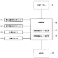
- the monitoring system 1 of the first embodiment includes a high pressure side pressure detection unit 11, a low pressure side pressure detection unit 12, an outside air temperature detection unit 13, an inside air temperature detection unit 14, a control device 15, and The notification unit 16 and the like are provided.
- the high pressure side pressure detection unit 11 is a pressure sensor that detects the pressure (hereinafter referred to as “cycle high pressure Pd”) of the refrigerant flowing in the high pressure side circuit from the refrigerant discharge port 31 of the compressor 3 to the expansion valve 5 in the refrigeration cycle apparatus 2 It is.
- the high pressure side pressure detection unit 11 is installed in the first high pressure pipe 71, the condenser 4 or the second high pressure pipe 72 or the like.
- the low pressure side pressure detection unit 12 is a pressure sensor that detects the pressure (hereinafter referred to as “cycle low pressure Ps”) of the refrigerant flowing in the low pressure side circuit from the expansion valve 5 to the suction port 32 of the compressor 3 in the refrigeration cycle apparatus 2 is there.
- the low pressure side pressure detection unit 12 is installed in the first low pressure pipe 73, the evaporator 6, the second low pressure pipe 74, or the like.
- the outside air temperature detection unit 13 is a temperature sensor that detects an air temperature outside the vehicle (hereinafter referred to as “outside air temperature Tamb”).
- the inside air temperature detection unit 14 is a temperature sensor that detects an air temperature inside the vehicle cabin (hereinafter referred to as “inside air temperature Tcab”).
- the control device 15 includes a processor and a known microcomputer having storage units such as ROM and RAM.
- the storage unit is configured of a non-transitional substantial storage medium.
- control device 15 included in the monitoring system 1 will be described as being integrally configured with the refrigeration cycle device 2 and the air conditioning control device that controls the operation of each part of the air conditioner.
- control apparatus 15 which comprises the monitoring system 1, and an air-conditioning control apparatus may be comprised separately.
- the control device 15 functions as the condenser air volume setting unit 17, and based on the vehicle interior set temperature and the vehicle interior temperature, the air volume mode of the air outside the vehicle ventilated to the condenser 4 by the outdoor blower 8 (hereinafter referred to Set the air volume mode Mcond). Further, the control device 15 functions as the evaporator air volume setting unit 18, and sets an air volume mode (hereinafter referred to as "air volume mode Meva of the evaporator 6") of air blown to the evaporator 6 by the indoor blower 10.
- the condenser air volume setting unit 17 and the evaporator air volume setting unit 18 set the air volume mode Mcond of the condenser 4 and the air volume mode Meva of the evaporator 6 larger as the difference between the vehicle interior set temperature and the vehicle interior temperature is larger. Do. Further, the smaller the difference between the vehicle interior temperature and the vehicle interior temperature is, the smaller the air volume mode Mcond of the condenser 4 and the air volume mode Meva of the evaporator 6 are set as the condenser air volume setting unit 17 and the evaporator air volume setting unit 18 decrease. Do. Then, the control device 15 detects the air volume mode Mcond of the condenser 4 set by the condenser air volume setting unit 17. The control device 15 can also detect the air volume of the condenser 4 from the vehicle speed information and the like. Further, the control device 15 detects the air volume mode Meva of the evaporator 6 set by the evaporator air volume setting unit 18.
- the control device 15 is information detected by the high pressure side pressure detection unit 11, the low pressure side pressure detection unit 12, the outside air temperature detection unit 13, the inside air temperature detection unit 14, the condenser air volume setting unit 17, and the evaporator air volume setting unit 18. Thus, the refrigerant flowing through the refrigeration cycle apparatus 2 is monitored.
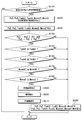
- control processing executed by the control device 15 of the first embodiment will be described with reference to the flowchart of FIG. 3.
- step S10 the control device 15 determines whether or not the current control process is the first process after the ignition key is turned on.
- the control apparatus 15 shifts the next process to step S20.
- step S20 is omitted, and the next process is transferred to step S30. .
- step S20 the control device 15 stores the cycle high pressure Pd1, the cycle low pressure Ps1, the outside air temperature Tamb1, the inside air temperature Tcab1, the air flow mode Mcond1 of the condenser 4, and the air flow mode Meva1 of the evaporator 6 detected in the previous control process. Read from the department. Then, the control device 15 shifts the process to step S30.
- "previous control process” refers to control process executed when the ignition key of the vehicle was turned on last time.
- step S30 the control device 15 measures the current cycle high pressure Pd2 by the high pressure side pressure detection unit 11, and measures the current cycle low pressure Ps2 by the low pressure side pressure detection unit 12. Further, the control device 15 measures the current outside air temperature Tamb2 by the outside air temperature detection unit 13, and measures the current inside air temperature Tcab2 by the inside air temperature detection unit 14. Further, the control device 15 detects the current air volume mode Mcond2 of the condenser 4 from the condenser air volume setting unit 17, and detects the current air volume mode Meva2 of the evaporator 6 from the evaporator air volume setting unit 18. Then, the control device 15 shifts the process to step S40.
- step S40 the controller 15 determines whether the current cycle high pressure Pd2 is lower than the cycle high pressure Pd1 detected in the previous control process, and further, the current cycle low pressure Ps2 is lower than the cycle low pressure Ps1 detected in the previous control process It is determined whether or not.
- the solid line ⁇ in FIG. 4 represents the transition of the state of the refrigerant when the amount of the refrigerant is sufficient in the circuit of the refrigeration cycle apparatus 2 on a Mollier diagram.
- A1 in FIG. 4 indicates the state of the refrigerant discharged from the compressor 3
- A2 indicates the state of the refrigerant flowing out of the condenser 4
- A3 indicates the state of the refrigerant decompressed by the expansion valve 5
- A4 indicates evaporation The state of the refrigerant flowing out of the vessel 6 is shown.
- the broken line ⁇ in FIG. 4 represents the transition of the state of the refrigerant when the amount of refrigerant in the circuit of the refrigeration cycle device 2 runs short on a Mollier diagram. If the amount of refrigerant is insufficient, the pressure of the high-pressure refrigerant discharged from the compressor 3 decreases and the cycle high pressure Pd decreases, as indicated by B1 in FIG. 4. Further, as indicated by B2 in FIG. 4, the degree of subcooling of the refrigerant on the refrigerant outlet side of the condenser 4 is reduced. The decrease amount ⁇ PH of the cycle high pressure Pd increases as the amount of refrigerant in the circuit runs short. Further, the decrease amount ⁇ SC of the degree of subcooling of the refrigerant increases as the amount of refrigerant in the circuit runs short.
- the pressure of the low pressure refrigerant flowing out of the expansion valve 5 decreases as indicated by B3 in FIG. 4, and the cycle low pressure Ps decreases.
- the pressure of the low pressure refrigerant sucked into the compressor 3 decreases, and the degree of superheat of the refrigerant on the refrigerant outlet side of the evaporator 6 increases.
- the decrease amount ⁇ PL of the cycle low pressure Ps and the increase amount ⁇ SH of the degree of superheat of the refrigerant increase as the amount of refrigerant in the circuit runs short.
- the refrigeration cycle apparatus 2 has a characteristic that the cycle high pressure Pd and the cycle low pressure Ps both decrease when the amount of refrigerant in the circuit decreases from the design leakage amount and the refrigerant shortage occurs.
- the control device 15 performs the following process in step S40 of FIG. That is, when the current cycle high pressure Pd2 is lower than the cycle high pressure Pd1 detected in the previous control process and the current cycle low pressure Ps2 is lower than the cycle low pressure Ps1 detected in the previous control process in step S40. Then, the process proceeds to step S50. If both the current cycle high pressure Pd2 and the cycle low pressure Ps2 are lower than the previously measured values Pd1 and Ps1, there is a possibility that the amount of refrigerant is insufficient.
- the control device 15 shifts the process to step S120.
- the control device 15 also shifts the process to step S120 when the current cycle low pressure Ps2 is equal to or higher than the cycle low pressure Ps1 detected in the previous control process. If either the current cycle high pressure Pd2 or the current cycle low pressure Ps2 is equal to the previous measured value Pd1 or Ps1 or is higher than the previous measured value Pd1 or Ps1, it can not be said that the amount of refrigerant is insufficient. is there.
- step S120 the process of step S120 will be described later.
- step S40 it is determined in step S40 that the current cycle high pressure Pd2 is lower than the cycle high pressure Pd1 detected in the previous control process, and the current cycle low pressure Ps2 is lower than the cycle low pressure Ps1 detected in the previous control process. If so, the process proceeds to step S50. Then, the processes of steps S50 to S80 described below are performed.
- step S50 the control device 15 determines whether the current outside air temperature Tamb2 is equal to or higher than the outside air temperature Tamb1 detected in the previous control process.
- the condensation of the refrigerant is promoted in the condenser 4 and the cycle high pressure Pd may be lowered.
- the current outside air temperature Tamb2 is lower than the outside air temperature Tamb1 detected in the previous control process, evaporation of the refrigerant may be suppressed by the evaporator 6, and the cycle low pressure Ps may be reduced.
- the control device 15 avoids the determination of the refrigerant shortage and shifts the process to step S120.
- the control device 15 determines that the current outside air temperature Tamb2 is equal to or higher than the outside air temperature Tamb1 detected in the previous control process, the process proceeds to step S60.
- step S60 the control device 15 determines whether or not the current inside temperature Tcab2 is equal to or higher than the inside temperature Tcab1 detected in the previous control processing.
- the control device 15 avoids the determination of the refrigerant shortage and shifts the processing to step S120.
- the control device 15 shifts the process to step S70.
- step S70 the control device 15 determines whether the current air volume mode Mcond2 of the condenser 4 is equal to or less than the air volume mode Mcond1 of the condenser 4 detected in the previous control process. If the current air volume mode Mcond2 of the condenser 4 is larger than the air volume mode Mcond1 of the condenser 4 detected in the previous control process, condensation of the refrigerant may be promoted in the condenser 4 and the cycle high pressure Pd may decrease.
- the control device 15 avoids the determination of the refrigerant shortage and shifts the process to step S120.
- the control device 15 determines that the current air volume mode Mcond2 of the condenser 4 is equal to or less than the air volume mode Mcond1 of the condenser 4 detected in the previous control process, the process proceeds to step S80.
- step S80 the control device 15 determines whether the current air volume mode Meva2 of the evaporator 6 is equal to or higher than the air volume mode Meva1 of the evaporator 6 detected in the previous control process. If the current air volume mode Meva2 of the evaporator 6 is smaller than the air volume mode Meva1 of the evaporator 6 detected in the previous control process, evaporation of the refrigerant may be suppressed in the evaporator 6 and the cycle low pressure Ps may be reduced.
- the control device 15 avoids the determination of the refrigerant shortage and shifts the process to step S120.
- the control device 15 determines that the current air volume mode Meva2 of the evaporator 6 is equal to or higher than the air volume mode Meva1 of the evaporator 6 detected in the previous control process, the process proceeds to step S90.
- step S90 based on the determinations in steps S40 to S80 described above, the control device 15 determines that the amount of refrigerant in the circuit is less than the design leakage amount, that is, the refrigerant is insufficient. Then, the control device 15 shifts the process to step S100.
- the notification unit 16 notifies an occupant or the like that the refrigeration cycle device 2 is in a state of insufficient refrigerant, in accordance with an instruction from the control device 15.
- the notification unit 16 can be configured by a display panel or a buzzer not shown.
- the display panel visually indicates to the occupant or the like that the refrigeration cycle apparatus 2 is in a state of refrigerant shortage.
- reports with a sound that the refrigerating-cycle apparatus 2 is a state with a refrigerant
- the notification unit 16 urges the occupant or the like to perform maintenance or the like by the notification operation such as the display panel or the buzzer.
- the control device 15 shifts the process to step S110.
- step S110 the control device 15 performs control to reduce the load on the compressor 3. Specifically, when the compressor 3 is configured to rotate with the rotation of the engine, the control device 15 performs control to reduce the amount of compression of the refrigerant by the compressor 3 by a clutch operation or the like. In addition, when the compressor 3 is driven by a motor, the control device 15 performs control such as reducing the rotational speed of the motor. After step S110, the control device 15 once terminates this control process.
- the control device 15 performs the following process in step S120. That is, the control device 15 replaces the current cycle high pressure Pd2 and cycle low pressure Ps2 detected in step S30 with the cycle high pressure Pd1 and cycle low pressure Ps1 detected in the previous control process, respectively, and stores them in the storage unit. Further, the control device 15 replaces the current outside temperature Tamb2 and the inside temperature Tcab2 detected in step S30 with the outside temperature Tamb1 and the inside temperature Tcab1 detected in the previous control process, respectively, and stores them in the storage unit.
- control device 15 replaces the current air volume mode Mcond2 of the condenser 4 detected in step S30 with the air volume mode Mcond1 of the condenser 4 detected in the previous control process, and stores the same in the storage unit.
- control device 15 replaces the current air volume mode Meva2 of the evaporator 6 detected in step S30 with the air volume mode Meva1 of the evaporator 6 detected in the previous control process, and stores it in the storage unit. Then, the control device 15 once terminates this control process, and repeatedly executes this process every predetermined time.
- the monitoring system 1 of the first embodiment described above has the following effects.
- the control device 15 determines that the refrigerant is insufficient.
- the conditions are that (A) both the cycle high pressure Pd2 and the cycle low pressure Ps2 are lower than the previously detected values Pd1 and Ps1.
- the outside air temperature Tamb2 is equal to or higher than the previously detected value Tamb1.
- the inside temperature Tcab2 is greater than or equal to the previous detection value Tcab1.
- the air volume mode Mcond2 of the condenser 4 is less than the previous air volume mode Mcond1.
- the air volume mode Meva2 of the evaporator 6 is equal to or higher than the previous air volume mode Meva1.
- both the cycle high pressure Pd and the cycle low pressure Ps decrease.
- the cycle high pressure Pd may decrease.
- the control device 15 may perform the determination of the refrigerant shortage early and accurately at a stage where the refrigerant leaks more than the design leak amount filled in the circuit while avoiding the determination of the refrigerant shortage in such a case. It is possible.
- the notification unit 16 performs the notification operation accompanying the determination of the control device 15. By prompting the occupant or the like of maintenance or the like by the notification unit 16, it is possible to prevent breakdown of the devices constituting the refrigeration cycle apparatus 2 in advance, and to suppress customer complaints and the like accompanying deterioration of the air conditioning function.
- the control device 15 determines that the refrigerant cycle device 2 is short of refrigerant, the control device 15 performs control to reduce the load of the compressor 3.
- the monitoring system 1 can prevent the failure of the compressor 3 by performing control to reduce the load of the compressor 3 when the refrigerant is insufficient.
- the second embodiment will be described with reference to FIG.
- the second embodiment is a modification of the first embodiment, in which the control process executed by the monitoring system 1 is changed.
- the control process described in the second embodiment may be performed continuously or simultaneously with the control process described in the first embodiment, or may be performed separately.
- step S110 the control device 15 determines whether or not a predetermined period of time has elapsed from the previous measurement in the current control process.
- the conventional measurement can be set, for example, to the previous measurement or several days to several tens of days, and the predetermined period can be set, for example, to several days to several tens of days.
- the control device 15 shifts the process to step S120.
- the control device 15 determines that the predetermined time period has not elapsed from the previous measurement, the control device 15 once ends the processing.
- step S120 the control device 15 detects the cycle high pressure Pd3 detected before the predetermined period, the cycle low pressure Ps3 detected before the predetermined period, the outside temperature Tamb3 detected before the predetermined period, the inside temperature Tcab3 detected before the predetermined period, the predetermined period
- the air volume mode Mcond3 of the condenser 4 detected before and the air volume mode Meva3 of the evaporator 6 detected before the predetermined period are read out from the storage unit. Then, the control device 15 shifts the process to step S130.
- step S130 the control device 15 controls the current cycle high pressure Pd2, the current cycle high pressure Pd2, the current cycle low pressure Ps2, the current outside temperature Tamb2, the current inside temperature Tcab2, the current volume mode Mcond2 of the condenser 4, and The current air volume mode Meva2 of the evaporator 6 is detected. Then, the control device 15 shifts the process to step S140.
- step S140 the control device 15 determines whether a value obtained by subtracting the cycle high pressure Pd2 detected this time from the cycle high pressure Pd3 detected before the predetermined period is larger than a first set value Th1. Furthermore, the control device 15 determines whether or not a value obtained by subtracting the cycle low pressure Ps2 detected this time from the cycle low pressure Ps3 detected before the predetermined period is larger than the second set value Th2.
- the control device 15 stores the decrease width of the cycle high pressure Pd and the decrease width of the cycle low pressure Ps according to the refrigerant leakage amount predicted in the predetermined period as the first set value Th1 and the second set value Th2, respectively. Is possible. Therefore, if the cycle high pressure Pd and cycle low pressure Ps measured before a predetermined period are compared with the cycle high pressure Pd and cycle low pressure Ps measured this time, the amount of refrigerant leakage for the predetermined period is a slow leak planned for design.
- abnormality of the air volume which passes an evaporator the abnormal stop of a blower, the clogging of an air filter, etc. can be considered, for example.
- abnormal decrease of the refrigerant flow rate for example, an abnormality of the expansion valve, a clogging of the liquid pipe, etc. can be considered.
- step S140 the control device 15 determines that a value obtained by subtracting the cycle high pressure Pd2 detected from the cycle high pressure Pd3 detected before the predetermined period is larger than the first set value Th1 and detects the cycle low pressure Ps3 before the predetermined period. If the value obtained by subtracting the cycle low pressure Ps2 detected this time from the value is larger than the second set value Th2, the process proceeds to step S150.
- step S140 when the value obtained by subtracting the cycle high pressure Pd2 detected this time from the cycle high pressure Pd3 detected before the predetermined period is the first set value Th1 or less in step S140, the control device 15 shifts the processing to step S220. Also, in step S140, the control device 15 shifts the process to step S220 also when the value obtained by subtracting the cycle low pressure Ps2 detected this time from the cycle low pressure Ps3 detected before the predetermined period is less than the second set value Th2. . In these cases, it can not be said that a circuit abnormality has occurred. The process of step S220 will be described later.
- step S150 to step S180 are substantially common to the processes described in step S50 to step S80 of the first embodiment.
- step S150 the control device 15 determines whether the outside air temperature Tamb2 detected this time is equal to or higher than the outside air temperature Tamb3 detected before a predetermined period. When the outside air temperature Tamb2 detected this time is lower than the outside air temperature Tamb3 detected before the predetermined period, the control device 15 shifts the processing to step S220. On the other hand, when the control device 15 determines that the outside air temperature Tamb2 detected this time is equal to or higher than the outside air temperature Tamb3 detected before the predetermined period, the process proceeds to step S160.
- step S160 the control device 15 determines whether the inside temperature Tcab2 detected this time is equal to or higher than the inside temperature Tcab3 detected before a predetermined period. When the inside temperature Tcab2 detected this time is lower than the inside temperature Tcab3 detected before the predetermined period, the control device 15 shifts the processing to step S220. On the other hand, when the control device 15 determines that the inside temperature Tcab2 detected this time is equal to or higher than the inside temperature Tcab3 detected before the predetermined period, the process proceeds to step S170.
- step S170 the control device 15 determines whether or not the air volume mode Mcond2 of the condenser 4 detected this time is equal to or less than the air volume mode Mcond3 of the condenser 4 detected before a predetermined period.
- the control device 15 shifts the process to step S220.
- the control device 15 determines that the air volume mode Mcond2 of the condenser 4 detected this time is equal to or less than the air volume mode Mcond3 of the condenser 4 detected before the predetermined period, the process proceeds to step S180.
- step S180 the control device 15 determines whether the air volume mode Meva2 of the evaporator 6 detected this time is equal to or higher than the air volume mode Meva3 of the evaporator 6 detected before a predetermined period.
- the control device 15 shifts the process to step S220.
- the control device 15 determines that the air volume mode Meva2 of the evaporator 6 detected this time is equal to or higher than the air volume mode Meva3 of the evaporator 6 detected before the predetermined period, the process proceeds to step S190.
- step S190 the control device 15 determines that a circuit abnormality has occurred in the refrigeration cycle device 2 based on the determinations in steps S140 to S180 described above. Then, the control device 15 shifts the process to step S200.
- step S200 the notification unit 16 notifies an occupant or the like that a circuit abnormality has occurred in the refrigeration cycle apparatus 2 in accordance with an instruction from the control device 15.
- the display panel as the notification unit 16 visually indicates to a passenger or the like that a circuit abnormality has occurred in the refrigeration cycle apparatus 2.
- reports that the circuit abnormality has generate
- the notification unit 16 urges the occupant or the like to perform maintenance or the like by the notification operation such as the display panel or the buzzer.
- the control device 15 shifts the process to step S210.
- control is performed to reduce the load on the compressor 3 as in the process described in step S110 of the first embodiment. After step S210, the control device 15 once terminates this control process.
- the control device 15 performs the following process in step S220. That is, the control device 15 replaces the currently detected cycle high pressure Pd2 and cycle low pressure Ps2 detected in step S130 with cycle high pressure Pd3 and cycle low pressure Ps3 detected in the control process before the predetermined period, respectively, and stores them in the storage unit.
- the control device 15 replaces the currently detected outside air temperature Tamb2 and the inside air temperature Tcab2 detected in step S130 with the outside air temperature Tamb3 and the inside air temperature Tcab3 detected in the control process of the predetermined period, respectively.
- the control device 15 replaces the currently detected outside air temperature Tamb2 and the inside air temperature Tcab2 detected in step S130 with the outside air temperature Tamb3 and the inside air temperature Tcab3 detected in the control process of the predetermined period, respectively.
- control device 15 replaces the air volume mode Mcond2 of the condenser 4 detected at this time in step S130 with the air volume mode Mcond3 of the condenser 4 detected in the control process before the predetermined period, and stores it in the storage unit. . Further, the control device 15 replaces the air volume mode Meva2 of the evaporator 6 detected at this time in step S130 with the air volume mode Meva3 of the evaporator 6 detected in the control process before the predetermined period, and stores it in the storage unit. . Then, the control device 15 once terminates this control process, and repeatedly executes this process every predetermined time.
- the monitoring system 1 of the second embodiment described above has the following effects.
- the control device 15 determines that a circuit abnormality has occurred in the refrigeration cycle device 2.
- the condition is that (F) a value obtained by subtracting the cycle high pressure Pd2 detected this time from the cycle high pressure Pd3 detected before the predetermined period is larger than the first set value Th1.
- the outside air temperature Tamb2 detected this time is equal to or higher than the detection value Tamb3 detected before a predetermined period.
- the inside temperature Tcab2 detected this time is equal to or more than the detection value Tcab3 detected before a predetermined period.
- the air volume mode Mcond2 of the condenser 4 detected this time is equal to or less than the air volume mode Meva3 detected before the predetermined period.
- the air volume mode Meva2 of the evaporator 6 detected this time is equal to or higher than the air volume mode Meva3 detected before the predetermined period.
- the control device 15 sets the decrease width of the cycle high pressure Pd and the decrease width of the cycle low pressure Ps according to the refrigerant leakage amount predicted in the predetermined period as the first set value Th1 and the second set value Th2, respectively.
- the cycle high pressure Ps is 2) The value decreases more than the set value Th2.
- the cycle high pressure Pd may be lowered more than the first set value Th1.
- the control device 15 may perform the circuit abnormality determination early and accurately at the stage where the refrigerant leaks more than the design leakage amount predicted in the predetermined period while avoiding the circuit abnormality determination. It is possible.
- the circuit abnormality means an abnormality in the air volume passing through the evaporator or an abnormality in the refrigerant flow rate.
- the notification unit 16 when the control device 15 determines that the circuit abnormality has occurred in the refrigeration cycle apparatus 2, the notification unit 16 notifies the occupant or the like of the circuit abnormality. According to this, when the notification unit 16 gives notification of the circuit abnormality, it is possible for the passenger or the dealer or the like to promptly and appropriately take measures such as searching for a coolant leakage portion and repair.
- the shape of the components when referring to a positional relationship or the like, except in particular clearly the case and principle specific shape, etc. If to be limited to the positional relationship or the like, the shape, It is not limited to the positional relationship and the like.
- steps S40 to S80 may be performed in different order.
- steps S140 to S180 may be performed in different order.
- steps S100, S110, S200, and S210 may be omitted as appropriate.
- the monitoring system includes a refrigeration cycle in which a compressor, a condenser, an expansion valve, and an evaporator are connected by piping and mounted on a moving body. Monitor the device.
- the monitoring system includes a high pressure side pressure detection unit, a low pressure side pressure detection unit, an outside air temperature detection unit, an inside air temperature detection unit, and a control device.
- the high pressure side pressure detection unit detects the pressure of the refrigerant flowing in the high pressure side circuit from the discharge port of the compressor to the expansion valve in the refrigeration cycle apparatus.
- the low pressure side pressure detection unit detects the pressure of the refrigerant flowing in the low pressure side circuit from the expansion valve to the suction port of the compressor.
- the outside air temperature detection unit detects the air temperature outside the vehicle.
- the inside air temperature detection unit detects the air temperature in the vehicle compartment.
- the controller can set the air flow mode of the condenser and the air flow mode of the evaporator. In this configuration, when all of the following conditions (A) to (E) are satisfied, the control device determines that the refrigerant flowing in the refrigeration cycle device is insufficient.
- the condition is that (A) the detection value of the high pressure side pressure detection unit is lower than the previous detection value, and the detection value of the low pressure side pressure detection unit is lower than the previous detection value.
- the detection value of the outside air temperature detection unit is equal to or more than the previous detection value.
- the detection value of the inside air temperature detection unit is equal to or more than the previous detection value.
- the air flow mode of the condenser is less than the previous air flow mode.
- the air volume mode of the evaporator is equal to or higher than the previous air volume mode.
- the control device stores, as the first set value, the reduction width of the refrigerant pressure of the high pressure side circuit according to the refrigerant leakage amount predicted in the predetermined period, and the refrigerant leakage predicted in the predetermined period
- the decrease width of the refrigerant pressure of the low pressure side circuit according to the amount is stored as a second set value.
- the control device determines that a circuit abnormality has occurred in the refrigeration cycle device.
- the condition is that (F) a value obtained by subtracting the detection value detected by the high pressure side pressure detection unit this time from the detection value detected by the high pressure side pressure detection unit a predetermined period before is larger than the first set value.
- a value obtained by subtracting the detection value currently detected by the low pressure side pressure detection unit from the detection value detected by the low pressure side pressure detection unit before the predetermined period is larger than the second set value.
- the detection value detected by the outside air temperature detection unit this time is equal to or more than the detection value detected by the outside air temperature detection unit before the predetermined period.
- the detection value detected by the inside air temperature detection unit this time is equal to or more than the detection value detected by the inside air temperature detection unit before the predetermined period.
- the air flow mode of the condenser is equal to or less than the air flow mode detected before the predetermined period.
- the air flow mode of the evaporator is equal to or higher than the air flow mode detected before the predetermined period.
- the control device uses the reduction width of the refrigerant pressure in the high-pressure circuit and the reduction width of the refrigerant pressure in the low-pressure circuit according to the refrigerant leakage amount predicted in the predetermined period as the first set value and the second set value. It is possible to memorize. Therefore, the control device determines that the circuit is abnormal when the decrease width of the refrigerant pressure of the high pressure side circuit in the predetermined period is larger than the first set value and the decrease width of the refrigerant pressure of the low pressure side circuit is larger than the second set value. It is possible.
- the circuit abnormality is, for example, an abnormality in which the refrigerant is likely to leak due to deterioration of the rubber hose or packing, an abnormality in the air volume passing through the evaporator (for example, abnormal stop of the blower, clogging of the air filter), or Anomalous reduction (for example, an abnormality in the expansion valve, a clogged fluid pipe).
- the monitoring system monitors the refrigeration cycle apparatus in which the compressor, the condenser, the expansion valve, and the evaporator are connected by piping and mounted on the moving body.
- the monitoring system includes a high pressure side pressure detection unit, a low pressure side pressure detection unit, an outside air temperature detection unit, an inside air temperature detection unit, and a control device.
- the high pressure side pressure detection unit detects the pressure of the refrigerant flowing in the high pressure side circuit from the discharge port of the compressor to the expansion valve in the refrigeration cycle apparatus.
- the low pressure side pressure detection unit detects the pressure of the refrigerant flowing in the low pressure side circuit from the expansion valve to the suction port of the compressor.
- the outside air temperature detection unit detects the air temperature outside the vehicle.
- the inside air temperature detection unit detects the air temperature in the vehicle compartment.
- the controller can set the air flow mode of the condenser and the air flow mode of the evaporator.
- the control device stores, as the first set value, the reduction width of the refrigerant pressure of the high pressure side circuit according to the refrigerant leakage amount predicted in the predetermined period, and corresponds to the refrigerant leakage amount predicted in the predetermined period.
- the decrease width of the refrigerant pressure of the low pressure side circuit is stored as a second set value. Then, when all of the following conditions (F) to (K) are satisfied, the control device determines that a circuit abnormality has occurred in the refrigeration cycle device.
- the condition is that (F) a value obtained by subtracting the detection value detected by the high pressure side pressure detection unit this time from the detection value detected by the high pressure side pressure detection unit a predetermined period before is larger than the first set value. (G) A value obtained by subtracting the detection value currently detected by the low pressure side pressure detection unit from the detection value detected by the low pressure side pressure detection unit before the predetermined period is larger than the second set value. (H) The detection value detected by the outside air temperature detection unit this time is equal to or more than the detection value detected by the outside air temperature detection unit before the predetermined period. (I) The detection value detected by the inside air temperature detection unit this time is equal to or more than the detection value detected by the inside air temperature detection unit before the predetermined period. (J) The air flow mode of the condenser is equal to or less than the air flow mode detected before the predetermined period. (K) The air flow mode of the evaporator is equal to or higher than the air flow mode detected before the predetermined period.
- the monitoring system further includes a notification unit that performs a notification operation associated with the determination of the control device. According to this, the monitoring system can urge maintenance and the like to the occupant and the like by the notification unit. As a result, it is possible to prevent failures of the devices constituting the refrigeration cycle apparatus and to prevent customer complaints and the like accompanying deterioration of the air conditioning function.
- the notification unit when the control device determines that the refrigerant flowing through the refrigeration cycle device is insufficient, the notification unit performs notification of the insufficient refrigerant. Further, the notification unit gives notification of the circuit abnormality when the control device determines the circuit abnormality of the refrigeration cycle device. According to this, it is possible for the passenger, the dealer, or the like to perform the replenishment of the refrigerant by the notification unit notifying the insufficient refrigerant. Furthermore, when the notification unit gives notification of the circuit abnormality, it is possible for the passenger or the dealer or the like to promptly and appropriately take measures such as searching for a coolant leakage portion and repair.
- the control device performs control to reduce the load on the compressor when it is determined that the refrigerant cycle device is insufficient in refrigerant.
- the load on the compressor increases, which may lead to failure of the compressor. Therefore, this monitoring system can prevent the failure of the compressor by performing control to reduce the load of the compressor when the refrigerant is insufficient.
Landscapes
- Engineering & Computer Science (AREA)
- Physics & Mathematics (AREA)
- Mechanical Engineering (AREA)
- Thermal Sciences (AREA)
- General Engineering & Computer Science (AREA)
- Air-Conditioning For Vehicles (AREA)
Abstract
監視システム(1)が備える制御装置(15)は、次の(A)~(E)の条件を全て満たしたとき、冷凍サイクル装置(2)を流れる冷媒が不足していることを判定する。その条件とは、(A)高圧側圧力検出部の検出値(Pd2)が前回検出値(Pd1)より低く、低圧側圧力検出部の検出値(Ps2)が前回検出値(Ps1)より低い。(B)外気温検出部の検出値(Tamb2)が前回検出値(Tamb1)以上である。(C)内気温検出部の検出値(Tcab2)が前回検出値(Tcab1)以上である。(D)凝縮器の風量モード(Mcond2)が前回の風量モード(Mcond1)以下である。(E)蒸発器の風量モード(Meva2)が前回の風量モード(Meva1)以上である。
Description
本出願は、2017年8月2日に出願された日本特許出願番号2017-149811号と、2018年6月29日に出願された日本特許出願番号2018-124917号とに基づくもので、ここにその記載内容が参照により組み入れられる。
本開示は、移動体に搭載される冷凍サイクル装置を監視する監視システムに関するものである。
従来、冷凍サイクル装置を循環する冷媒量を監視する監視システムが知られている。
特許文献1に記載の技術は、冷凍サイクル装置の回路に設けられたレシーバに貯留された冷媒の液面の高さを検知することで、冷凍サイクル装置を循環する冷媒量が適正か否かを判定するものである。
ところで、上述した特許文献1に記載の技術は、家庭用エアコンやビル空調など定置式の冷凍サイクル装置に適用されるものである。この種の冷凍サイクル装置は、各配管が溶接等によって接合されており、振動などが殆どない環境で使用されるので、設計的に冷媒洩れが殆ど無いことを前提としたものである。
これに対し、移動体に搭載される冷凍サイクル装置は、外気温の変化や風速の変化などの外乱が多く、また、移動体と圧縮機とが異なる振動を伴うような環境で使用される。そのため、この冷凍サイクル装置では、それらの負荷を吸収するために冷凍サイクル装置の配管の一部にゴムホースが用いられる。そのため、冷凍サイクル装置では、そのゴムホースを通して冷媒が微小に洩れる、いわゆるスローリークを生じる。したがって、この冷凍サイクル装置では、製品の耐用年数またはメンテナンス期間内で問題の無い冷媒洩れ量が設計上算出され、回路内に充填されている。
よって、移動体に搭載される冷凍サイクル装置では、レシーバに貯留された液相冷媒の液面の高さを検知して冷媒量の適否を判定するという定置式を前提とした特許文献1の技術をそのまま適応することはできない。移動体に搭載される冷凍サイクル装置では、回路内に充填された設計洩れ量より多量の冷媒が洩れた場合、その冷媒洩れをできる限り早期に検知することが重要となる。仮に、冷媒洩れの検知が遅れると、空調機能が低下し、さらに、冷凍サイクル装置を構成する圧縮機等に故障が発生するおそれがある。
本開示は、移動体に搭載される冷凍サイクル装置の異常を早期かつ正確に判定することが可能な監視システムを提供することを目的とする。
本開示の1つの観点によれば、
圧縮機、凝縮器、膨張弁および蒸発器が配管で接続されて移動体に搭載される冷凍サイクル装置を監視する監視システムであって、
冷凍サイクル装置のうち圧縮機の吐出口から膨張弁までの高圧側回路を流れる冷媒の圧力を検出する高圧側圧力検出部と、
冷凍サイクル装置のうち膨張弁から圧縮機の吸込口までの低圧側回路を流れる冷媒の圧力を検出する低圧側圧力検出部と、
車室外の空気温度を検出する外気温検出部と、
車室内の空気温度を検出する内気温検出部と、
凝縮器の風量モードおよび蒸発器の風量モードを設定可能な制御装置と、を備え、
制御装置は、
高圧側圧力検出部の検出値が前回検出値より低く、
低圧側圧力検出部の検出値が前回検出値より低く、
外気温検出部の検出値が前回検出値以上であり、
内気温検出部の検出値が前回検出値以上であり、
凝縮器の風量モードが前回の風量モード以下であり、
蒸発器の風量モードが前回の風量モード以上のとき、冷凍サイクル装置を流れる冷媒が不足していることを判定する。
圧縮機、凝縮器、膨張弁および蒸発器が配管で接続されて移動体に搭載される冷凍サイクル装置を監視する監視システムであって、
冷凍サイクル装置のうち圧縮機の吐出口から膨張弁までの高圧側回路を流れる冷媒の圧力を検出する高圧側圧力検出部と、
冷凍サイクル装置のうち膨張弁から圧縮機の吸込口までの低圧側回路を流れる冷媒の圧力を検出する低圧側圧力検出部と、
車室外の空気温度を検出する外気温検出部と、
車室内の空気温度を検出する内気温検出部と、
凝縮器の風量モードおよび蒸発器の風量モードを設定可能な制御装置と、を備え、
制御装置は、
高圧側圧力検出部の検出値が前回検出値より低く、
低圧側圧力検出部の検出値が前回検出値より低く、
外気温検出部の検出値が前回検出値以上であり、
内気温検出部の検出値が前回検出値以上であり、
凝縮器の風量モードが前回の風量モード以下であり、
蒸発器の風量モードが前回の風量モード以上のとき、冷凍サイクル装置を流れる冷媒が不足していることを判定する。
これによれば、冷凍サイクル装置を流れる冷媒量が不足すると、冷凍サイクル装置の高圧側回路を流れる冷媒の圧力と、低圧側回路を流れる冷媒の圧力が共に低下する。ただし、車室外の空気温度が低いとき、凝縮器の風量モードが大きいときには、凝縮器で冷媒の凝縮が促進され、高圧側回路の冷媒の圧力が低下する場合がある。また、車室内の空気温度が低いとき、蒸発器の風量モードが小さいときには、蒸発器で冷媒の蒸発が抑制され、低圧側回路の冷媒の圧力が低下する場合がある。その場合には、制御装置は、冷媒不足の判定を避ける。そのため、制御装置は、高圧側回路と低圧側回路の冷媒圧力が共に前回計測値より低下しており、且つ、その冷媒の圧力低下が車室外および車室内の空気温度、凝縮器および蒸発器の風量によるものでないとき、冷媒不足の判定を行う。したがって、制御装置は、冷媒が回路内に充填された設計洩れ量以上に洩れた段階で、冷媒不足の判定を早期かつ正確に行うことが可能である。
また、別の観点によれば、
圧縮機、凝縮器、膨張弁および蒸発器が配管で接続されて移動体に搭載される冷凍サイクル装置を監視する監視システムであって、
冷凍サイクル装置のうち圧縮機の吐出口から膨張弁までの高圧側回路を流れる冷媒の圧力を検出する高圧側圧力検出部と、
冷凍サイクル装置のうち膨張弁から圧縮機の吸込口までの低圧側回路を流れる冷媒の圧力を検出する低圧側圧力検出部と、
車室外の空気温度を検出する外気温検出部と、
車室内の空気温度を検出する内気温検出部と、
凝縮器の風量モードおよび蒸発器の風量モードを設定可能な制御装置と、を備え、
制御装置は、所定期間に予測される冷媒洩れ量に応じた高圧側回路の冷媒圧力の低下幅を第1設定値として記憶し、所定期間に予測される冷媒洩れ量に応じた低圧側回路の冷媒圧力の低下幅を第2設定値として記憶しており、
高圧側圧力検出部が所定期間前に検出した検出値から今回検出した検出値を引いた値が第1設定値より大きく、
低圧側圧力検出部が所定期間前に検出した検出値から今回検出した検出値を引いた値が第2設定値より大きく、
外気温検出部が今回検出した検出値が所定期間前に検出した検出値以上であり、
内気温検出部が今回検出した検出値が所定期間前に検出した検出値以上であり、
凝縮器の風量モードが所定期間前に検出した風量モード以下であり、
蒸発器の風量モードが所定期間前に検出した風量モード以上のとき、冷凍サイクル装置に回路異常が発生していると判定する。
圧縮機、凝縮器、膨張弁および蒸発器が配管で接続されて移動体に搭載される冷凍サイクル装置を監視する監視システムであって、
冷凍サイクル装置のうち圧縮機の吐出口から膨張弁までの高圧側回路を流れる冷媒の圧力を検出する高圧側圧力検出部と、
冷凍サイクル装置のうち膨張弁から圧縮機の吸込口までの低圧側回路を流れる冷媒の圧力を検出する低圧側圧力検出部と、
車室外の空気温度を検出する外気温検出部と、
車室内の空気温度を検出する内気温検出部と、
凝縮器の風量モードおよび蒸発器の風量モードを設定可能な制御装置と、を備え、
制御装置は、所定期間に予測される冷媒洩れ量に応じた高圧側回路の冷媒圧力の低下幅を第1設定値として記憶し、所定期間に予測される冷媒洩れ量に応じた低圧側回路の冷媒圧力の低下幅を第2設定値として記憶しており、
高圧側圧力検出部が所定期間前に検出した検出値から今回検出した検出値を引いた値が第1設定値より大きく、
低圧側圧力検出部が所定期間前に検出した検出値から今回検出した検出値を引いた値が第2設定値より大きく、
外気温検出部が今回検出した検出値が所定期間前に検出した検出値以上であり、
内気温検出部が今回検出した検出値が所定期間前に検出した検出値以上であり、
凝縮器の風量モードが所定期間前に検出した風量モード以下であり、
蒸発器の風量モードが所定期間前に検出した風量モード以上のとき、冷凍サイクル装置に回路異常が発生していると判定する。
これによれば、移動体に搭載される冷凍サイクル装置では、所定期間に冷媒が洩れる量が設計上予測されている。そのため、その所定期間に予測される冷媒洩れ量に応じた高圧側回路の冷媒圧力の低下幅と、低圧側回路の冷媒圧力の低下幅をそれぞれ第1設定値および第2設定値として制御装置に記憶させることが可能である。したがって、制御装置は、所定期間における高圧側回路の冷媒圧力の低下幅が第1設定値より大きく、且つ、低圧側回路の冷媒圧力の低下幅が第2設定値より大きいとき、回路異常を判定することが可能である。なお、回路異常とは、例えばゴムホース・パッキンの劣化による冷媒が漏れやすい状況になっている異常、蒸発器を通る風量の異常、または、冷媒流量の異常低下をいう。なお、蒸発器を通る風量の異常として、例えば、ブロワの異常停止、エアフィルタの詰まりなどが考えられる。また、冷媒流量の異常低下として、例えば、膨張弁の異常、液配管の詰まりなどが考えられる。
なお、各構成要素等に付された括弧付きの参照符号は、その構成要素等と後述する実施形態に記載の具体的な構成要素等との対応関係の一例を示すものである。
以下、本開示の実施形態について図面を参照しつつ説明する。なお、以下の各実施形態相互において、互いに同一もしくは均等である部分には、同一符号を付し、その説明を省略する。
(第1実施形態)
第1実施形態について図面を参照しつつ説明する。第1実施形態の監視システム1は、移動体としての車両に搭載される冷凍サイクル装置2を循環する冷媒量を監視するシステムである。まず、第1実施形態の監視システム1が監視対象とする冷凍サイクル装置2について説明する。冷凍サイクル装置2は、車両の車室内の空気調和を行うための空調装置に適用されるものである。
第1実施形態について図面を参照しつつ説明する。第1実施形態の監視システム1は、移動体としての車両に搭載される冷凍サイクル装置2を循環する冷媒量を監視するシステムである。まず、第1実施形態の監視システム1が監視対象とする冷凍サイクル装置2について説明する。冷凍サイクル装置2は、車両の車室内の空気調和を行うための空調装置に適用されるものである。
図1に示すように、冷凍サイクル装置2は、圧縮機3、凝縮器4、膨張弁5および蒸発器6などが配管7により接続され、冷媒が充填された状態で車両に搭載されるものである。冷凍サイクル装置2に充填される冷媒は、例えばHFC系冷媒であるR134aが採用される。なお、冷媒には、圧縮機3を潤滑するオイル(すなわち、冷凍機油)が混入されている。オイルの一部は、冷媒と共に回路内を循環する。
圧縮機3は、蒸発器6側の低圧配管74から吸入した冷媒を圧縮し、凝縮器4側の高圧配管71に吐き出す。圧縮機3は、例えば、往復動式または回転式などの圧縮機構を含んで構成されている。圧縮機3は、車両に搭載される図示していないエンジンまたは電動機により駆動される。
凝縮器4は、圧縮機3から吐き出された高温高圧の冷媒を、室外送風機8から凝縮器4に送風される車室外空気(以下「外気」という)、または、車両の走行時の風圧により凝縮器4に送風される外気と熱交換させる熱交換器である。図1の破線矢印AFoで示すように、室外送風機8から送風される外気は、凝縮器4を通過する。凝縮器4を流れる冷媒は、凝縮器4に送風される外気に放熱し、凝縮する。
凝縮器4の下流側にレシーバ9が設けられている。レシーバ9は、凝縮器4から流出した冷媒を貯留し、液相冷媒のみを膨張弁5に送り出すものである。冷凍サイクル装置2には、製品の耐用年数またはメンテナンス期間内でスローリークする冷媒洩れ量が設計上算出され、回路内に充填されている。そのため、レシーバ9には、その設計上算出された洩れ量に相当する冷媒が貯留される。
膨張弁5は、凝縮器4を通過した冷媒を減圧膨張させる膨張弁5である。膨張弁5は、例えば、蒸発器6の出口側の温度に応じて弁開度が自動調整される温度式膨張弁が採用される。
蒸発器6は、車室内空間へ空気を送風する室内送風機10により送風される車室内空気(以下「内気」という)または外気と、膨張弁5で減圧された低温低圧の冷媒とを熱交換させる熱交換器である。図1の破線矢印AFcで示すように、室内送風機10から送風される空気は、蒸発器6を通過する。蒸発器6を流れる冷媒は、室内送風機10により送風される空気から吸熱して蒸発する。室内送風機10により送風される空気は、蒸発器6を通過する際に冷媒の蒸発潜熱により冷却された後、車室内へ吹き出される。
圧縮機3、凝縮器4、膨張弁5、蒸発器6は、複数の配管7により接続され、閉回路を構成している。具体的には、配管7は、第1高圧配管71、第2高圧配管72、第1低圧配管73および第2低圧配管74を含んで構成されている。第1高圧配管71は、圧縮機3の冷媒吐出口31と凝縮器4の冷媒入口側とを接続している。第2高圧配管72は、レシーバ9の冷媒出口側と膨張弁5の冷媒入口側とを接続している。第1低圧配管73は、膨張弁5の冷媒出口側と蒸発器6の冷媒入口側とを接続している。第2低圧配管74は、蒸発器6の冷媒出口側と圧縮機3の吸込口32とを接続している。
各配管7は、基本的に金属製の配管7で構成されている。但し、第1高圧配管71の一部と第2低圧配管74の一部は、エンジンや圧縮機3の振動を吸収するため、可撓性に優れたゴムまたは樹脂などの高分子材料で形成されている。高分子材料で形成された配管7は、金属製の配管7に比べて、ガス透過性が高いため、内部を流れる冷媒が徐々に外部に透過する。したがって、車両などの移動体に搭載される冷凍サイクル装置2では、高分子材料で形成された配管7や圧縮機3のシール部材などからの冷媒のスローリークが避けられない。そこで、第1実施形態の監視システム1は、この冷凍サイクル装置2の冷媒回路を循環する冷媒量を監視し、冷媒が回路内に充填された設計洩れ量以上に洩れた段階で、冷媒不足の判定を早期かつ正確に行うことを可能としている。
次に、第1実施形態の監視システム1について説明する。図1および図2に示すように、第1実施形態の監視システム1は、高圧側圧力検出部11、低圧側圧力検出部12、外気温検出部13、内気温検出部14、制御装置15および報知部16などを備えている。
高圧側圧力検出部11は、冷凍サイクル装置2のうち圧縮機3の冷媒吐出口31から膨張弁5までの高圧側回路を流れる冷媒の圧力(以下「サイクル高圧Pd」という)を検出する圧力センサである。高圧側圧力検出部11は、第1高圧配管71、凝縮器4または第2高圧配管72などに設置される。
低圧側圧力検出部12は、冷凍サイクル装置2のうち膨張弁5から圧縮機3の吸込口32までの低圧側回路を流れる冷媒の圧力(以下「サイクル低圧Ps」という)を検出する圧力センサである。低圧側圧力検出部12は、第1低圧配管73、蒸発器6または第2低圧配管74などに設置される。
外気温検出部13は、車室外の空気温度(以下「外気温Tamb」という)を検出する温度センサである。内気温検出部14は、車室内の空気温度(以下「内気温Tcab」という)を検出する温度センサである。
上述した高圧側圧力検出部11、低圧側圧力検出部12、外気温検出部13および内気温検出部14により検出された情報は、制御装置15に伝送される。制御装置15は、プロセッサと、ROMおよびRAM等の記憶部を有する周知のマイクロコンピュータを含んで構成されている。なお、記憶部は、非遷移的実体的記憶媒体で構成されている。
第1実施形態では、監視システム1が備える制御装置15は、冷凍サイクル装置2および空調装置の各部の動作を制御する空調制御装置と一体に構成されているものとして説明する。なお、監視システム1を構成する制御装置15と、空調制御装置とは、個別に構成されていてもよい。
制御装置15は、凝縮器風量設定部17として機能し、車室内設定温度と車室内温度に基づき、室外送風機8により凝縮器4に送風する車室外空気の風量モード(以下、「凝縮器4の風量モードMcond」という)を設定する。また、制御装置15は、蒸発器風量設定部18として機能し、室内送風機10により蒸発器6に送風する空気の風量モード(以下「蒸発器6の風量モードMeva」という)を設定する。なお、凝縮器風量設定部17と蒸発器風量設定部18は、車室内設定温度と車室内温度との差が大きいほど、凝縮器4の風量モードMcondと蒸発器6の風量モードMevaを大きく設定する。また、凝縮器風量設定部17と蒸発器風量設定部18は、車室内設定温度と車室内温度との差が小さいほど、凝縮器4の風量モードMcondと蒸発器6の風量モードMevaを小さく設定する。そして、制御装置15は、凝縮器風量設定部17が設定した凝縮器4の風量モードMcondを検出する。なお、制御装置15は、車速情報などから凝縮器4の風量を検出することも可能である。また、制御装置15は、蒸発器風量設定部18が設定した蒸発器6の風量モードMevaを検出する。
制御装置15は、上述した高圧側圧力検出部11、低圧側圧力検出部12、外気温検出部13、内気温検出部14、凝縮器風量設定部17および蒸発器風量設定部18により検出した情報により、冷凍サイクル装置2を流れる冷媒の監視を行う。以下、第1実施形態の制御装置15が実行する制御処理について、図3のフローチャートを参照して説明する。
この制御処理は、車両のイグニッションキーがオンされ、空調装置のスイッチがオンされているときに開始される。ステップS10で制御装置15は、今回の制御処理が、イグニッションキーがオンされてから初回の処理であるか否かを判定する。制御装置15は、今回の制御処理が、イグニッションキーがオンされてから初回の処理であると判定した場合、次の処理をステップS20に移行する。一方、ステップS10で制御装置15は、今回の制御処理が、イグニッションキーがオンされてから2回目以降の処理であると判定した場合、ステップS20を省略し、次の処理をステップS30に移行する。
ステップS20で制御装置15は、前回の制御処理で検出したサイクル高圧Pd1、サイクル低圧Ps1、外気温Tamb1、内気温Tcab1、凝縮器4の風量モードMcond1、および、蒸発器6の風量モードMeva1を記憶部から読み出す。そして、制御装置15は、処理をステップS30に移行する。なお、第1実施形態の説明において、「前回の制御処理」とは、車両のイグニッションキーが前回オンされたときに実行された制御処理をいう。
ステップS30で制御装置15は、高圧側圧力検出部11により現在のサイクル高圧Pd2を計測し、低圧側圧力検出部12により現在のサイクル低圧Ps2を計測する。また、制御装置15は、外気温検出部13により現在の外気温Tamb2を計測し、内気温検出部14により現在の内気温Tcab2を計測する。さらに制御装置15は、凝縮器風量設定部17から現在の凝縮器4の風量モードMcond2を検出し、蒸発器風量設定部18から現在の蒸発器6の風量モードMeva2を検出する。そして、制御装置15は、処理をステップS40に移行する。
ステップS40で制御装置15は、現在のサイクル高圧Pd2が前回の制御処理で検出したサイクル高圧Pd1より低いか否か、さらに、現在のサイクル低圧Ps2が前回の制御処理で検出したサイクル低圧Ps1より低いか否かを判定する。
ここで、冷凍サイクル装置2の特性について図4を参照して説明する。図4の実線αは、冷凍サイクル装置2の回路内に冷媒量が十分にあるときの冷媒の状態の推移をモリエル線図上に表したものである。図4のA1は圧縮機3から吐き出された冷媒の状態を示し、A2は凝縮器4から流出した冷媒の状態を示し、A3は膨張弁5により減圧された冷媒の状態を示し、A4は蒸発器6から流出した冷媒の状態を示している。
一方、図4の破線βは、冷凍サイクル装置2の回路内の冷媒量が不足したときの冷媒の状態の推移をモリエル線図上に表したものである。冷媒量が不足すると、図4のB1に示すように、圧縮機3から吐き出される高圧冷媒の圧力が低下し、サイクル高圧Pdが低下する。また、図4のB2に示すように、凝縮器4の冷媒出口側における冷媒の過冷却度が小さくなる。サイクル高圧Pdの低下量ΔPHは、回路内の冷媒量が不足するにつれて大きくなる。また、冷媒の過冷却度の減少量ΔSCは、回路内の冷媒量が不足するにつれて大きくなる。
また、冷媒量が不足すると、図4のB3に示すように、膨張弁5から流出する低圧冷媒の圧力が低下し、サイクル低圧Psが低下する。また、図4のB4に示すように、圧縮機3に吸入される低圧冷媒の圧力が低下すると共に、蒸発器6の冷媒出口側における冷媒の過熱度が大きくなる。サイクル低圧Psの低下量ΔPLおよび冷媒の過熱度の増加量ΔSHは、回路内の冷媒量が不足するにつれて大きくなる。
このように、冷凍サイクル装置2は、回路内の冷媒量が設計洩れ量より減少し、冷媒不足の状態になると、サイクル高圧Pdとサイクル低圧Psが共に低下するという特性がある。このような特性に基づき、図3のステップS40で制御装置15は、次の処理を行う。すなわち、ステップS40で制御装置15は、現在のサイクル高圧Pd2が前回の制御処理で検出したサイクル高圧Pd1より低く、且つ、現在のサイクル低圧Ps2が前回の制御処理で検出したサイクル低圧Ps1より低い場合、処理をステップS50に移行する。現在のサイクル高圧Pd2とサイクル低圧Ps2が共に前回計測値Pd1、Ps1より低下している場合、冷媒量が不足している可能性があるからである。
一方、ステップS40で制御装置15は、現在のサイクル高圧Pd2が前回の制御処理で検出したサイクル高圧Pd1以上である場合、処理をステップS120に移行する。また、制御装置15は、現在のサイクル低圧Ps2が前回の制御処理で検出したサイクル低圧Ps1以上である場合にも、処理をステップS120に移行する。現在のサイクル高圧Pd2または現在のサイクル低圧Ps2のいずれか一方が前回計測値Pd1、Ps1と同じであるか前回計測値Pd1、Ps1より高い場合、冷媒量が不足しているとは言えないからである。
例えば、現在の圧縮機3の回転数が、前回測定時の圧縮機3の回転数より高い場合、現在のサイクル高圧Pd2は前回のサイクル高圧Pd1より高くなり、現在のサイクル低圧Ps2は前回のサイクル低圧Ps1より低くなる。この場合、冷媒量が不足しているとは言えないので、処理はステップS120に移行する。ステップS120の処理については後述する。
上述のように、ステップS40で現在のサイクル高圧Pd2が前回の制御処理で検出したサイクル高圧Pd1より低く、且つ、現在のサイクル低圧Ps2が前回の制御処理で検出したサイクル低圧Ps1より低いと判定された場合、処理はステップS50に移行する。そして、次に説明するステップS50~ステップS80の処理が行われる。
ステップS50で制御装置15は、現在の外気温Tamb2が前回の制御処理で検出した外気温Tamb1以上であるか否かを判定する。現在の外気温Tamb2が前回の制御処理で検出した外気温Tamb1より低い場合は、凝縮器4で冷媒の凝縮が促進され、サイクル高圧Pdが低下することがある。また、現在の外気温Tamb2が前回の制御処理で検出した外気温Tamb1より低い場合は、蒸発器6で冷媒の蒸発が抑制され、サイクル低圧Psが低下することがある。そのため、制御装置15は、現在の外気温Tamb2が前回の制御処理で検出した外気温Tamb1より低い場合、冷媒不足の判定を避け、処理をステップS120に移行する。一方、制御装置15は、現在の外気温Tamb2が前回の制御処理で検出した外気温Tamb1以上であると判定した場合、処理をステップS60に移行する。
ステップS60で制御装置15は、現在の内気温Tcab2が前回の制御処理で検出した内気温Tcab1以上であるか否かを判定する。現在の内気温Tcab2が前回の制御処理で検出した内気温Tcab1より低い場合は、蒸発器6で冷媒の蒸発が抑制され、サイクル低圧Psが低下することがある。そのため、制御装置15は、現在の内気温Tcab2が前回の制御処理で検出した内気温Tcab1より低い場合、冷媒不足の判定を避け、処理をステップS120に移行する。一方、制御装置15は、現在の内気温Tcab2が前回の制御処理で検出した内気温Tcab1以上であると判定した場合、処理をステップS70に移行する。
ステップS70で制御装置15は、現在の凝縮器4の風量モードMcond2が前回の制御処理で検出した凝縮器4の風量モードMcond1以下であるか否かを判定する。現在の凝縮器4の風量モードMcond2が前回の制御処理で検出した凝縮器4の風量モードMcond1より大きい場合は、凝縮器4で冷媒の凝縮が促進され、サイクル高圧Pdが低下することがある。そのため、制御装置15は、現在の凝縮器4の風量モードMcond2が前回の制御処理で検出した凝縮器4の風量モードMcond1より大きい場合、冷媒不足の判定を避け、処理をステップS120に移行する。一方、制御装置15は、現在の凝縮器4の風量モードMcond2が前回の制御処理で検出した凝縮器4の風量モードMcond1以下であると判定した場合、処理をステップS80に移行する。
ステップS80で制御装置15は、現在の蒸発器6の風量モードMeva2が前回の制御処理で検出した蒸発器6の風量モードMeva1以上であるか否かを判定する。現在の蒸発器6の風量モードMeva2が前回の制御処理で検出した蒸発器6の風量モードMeva1より小さい場合は、蒸発器6で冷媒の蒸発が抑制され、サイクル低圧Psが低下することがある。そのため、制御装置15は、現在の蒸発器6の風量モードMeva2が前回の制御処理で検出した蒸発器6の風量モードMeva1より小さい場合、冷媒不足の判定を避け、処理をステップS120に移行する。一方、制御装置15は、現在の蒸発器6の風量モードMeva2が前回の制御処理で検出した蒸発器6の風量モードMeva1以上であると判定した場合、処理をステップS90に移行する。
ステップS90で制御装置15は、上述したステップS40~ステップS80の判定に基づき、回路内の冷媒量が設計洩れ量より減少している状態、すなわち、冷媒不足であると判定する。そして、制御装置15は、処理をステップS100に移行する。
ステップS100で報知部16は、制御装置15の指令に従い、乗員等に対して冷凍サイクル装置2が冷媒不足の状態にあることを報知する。なお、具体的には、報知部16は、図示していない表示パネルまたはブザーなどにより構成することが可能である。表示パネルは、冷凍サイクル装置2が冷媒不足の状態であることを乗員等に対して視覚的に表示する。また、ブザーは、冷凍サイクル装置2が冷媒不足の状態であることを音により報知する。これにより、報知部16は、表示パネルまたはブザーなどの報知動作により、乗員等にメンテナンス等を促す。次に、制御装置15は、処理をステップS110に移行する。
ステップS110で制御装置15は、圧縮機3の負荷を下げる制御を行う。具体的には、圧縮機3がエンジンの回転と共に回転する構成の場合、制御装置15はクラッチ動作などにより、圧縮機3による冷媒の圧縮量を低減する制御を行う。また、圧縮機3が電動機により駆動されるものである場合、制御装置15は電動機の回転数を下げる等の制御を行う。ステップS110の後、制御装置15は、この制御処理を一旦終了する。
一方、上述したステップS40~ステップS80で、処理がステップS120に移行すると、ステップS120で制御装置15は、次の処理を行う。すなわち、制御装置15は、ステップS30で検出した現在のサイクル高圧Pd2、サイクル低圧Ps2を、それぞれ、前回の制御処理で検出したサイクル高圧Pd1、サイクル低圧Ps1に置き替えて、記憶部に記憶する。また、制御装置15は、ステップS30で検出した現在の外気温Tamb2、内気温Tcab2を、それぞれ、前回の制御処理で検出した外気温Tamb1、内気温Tcab1に置き替えて、記憶部に記憶する。また、制御装置15は、ステップS30で検出した現在の凝縮器4の風量モードMcond2を、前回の制御処理で検出した凝縮器4の風量モードMcond1に置き替えて、記憶部に記憶する。また、制御装置15は、ステップS30で検出した現在の蒸発器6の風量モードMeva2を、前回の制御処理で検出した蒸発器6の風量モードMeva1に置き替えて、記憶部に記憶する。そして、制御装置15は、この制御処理を一旦終了し、所定時間経過ごとに繰り返し実行する。
以上説明した第1実施形態の監視システム1は、次の作用効果を奏するものである。
(1)第1実施形態では、制御装置15は、次の(A)~(E)の条件を全て満たしたとき、冷媒不足と判定する。その条件とは、(A)サイクル高圧Pd2とサイクル低圧Ps2が共に前回の検出値Pd1、Ps1より低い。(B)外気温Tamb2が前回の検出値Tamb1以上である。(C)内気温Tcab2が前回の検出値Tcab1以上である。(D)凝縮器4の風量モードMcond2が前回の風量モードMcond1以下である。(E)蒸発器6の風量モードMeva2が前回の風量モードMeva1以上である。
これによれば、冷凍サイクル装置2を流れる冷媒が不足すると、サイクル高圧Pdとサイクル低圧Psが共に低下する。ただし、外気温Tambが低いとき、または、凝縮器4の風量モードMcondが大きいときには、サイクル高圧Pdが低下する場合がある。また、内気温Tcabが低いとき、または、蒸発器6の風量モードMevaが小さいときには、サイクル低圧Psが低下する場合がある。したがって、制御装置15は、そのような場合は冷媒不足の判定を避けつつ、冷媒が回路内に充填された設計洩れ量以上に洩れた段階で、冷媒不足の判定を早期かつ正確に行うことが可能である。
(2)第1実施形態では、報知部16は、制御装置15の判定に伴う報知動作を行う。報知部16により、乗員等にメンテナンス等を促すことで、冷凍サイクル装置2を構成する機器の故障を未然に防ぐと共に、空調機能の低下に伴う顧客の苦情などを抑止することができる。
(3)第1実施形態では、制御装置15は、冷凍サイクル装置2の冷媒不足を判定したとき、圧縮機3の負荷を下げる制御を行う。一般に、冷凍サイクル装置2の冷媒が不足すると、圧縮機3への負荷が大きくなり、圧縮機3の故障に繋がるおそれがある。そこで、この監視システム1は、冷媒が不足したとき、圧縮機3の負荷を下げる制御を行うことで、圧縮機3の故障を未然に防ぐことができる。
(第2実施形態)
第2実施形態について、図5を参照して説明する。第2実施形態は、第1実施形態に対し、監視システム1が実行する制御処理を変更したものである。なお、第2実施形態で説明する制御処理は、第1実施形態で説明した制御処理に連続または同時に実行されてもよく、或いは、個別に実行されてもよい。
第2実施形態について、図5を参照して説明する。第2実施形態は、第1実施形態に対し、監視システム1が実行する制御処理を変更したものである。なお、第2実施形態で説明する制御処理は、第1実施形態で説明した制御処理に連続または同時に実行されてもよく、或いは、個別に実行されてもよい。
第2実施形態の制御処理について、図5のフローチャートを参照して説明する。この制御処理は、車両のイグニッションキーがオンされ、空調装置のスイッチがオンされているときに開始される。ステップS110で制御装置15は、今回の制御処理が、従前の計測から所定期間経過しているか否かを判定する。従前の計測とは、例えば前回の計測や数日~数十日に設定することが可能であり、所定期間とは、例えば数日~数十日に設定することが可能である。制御装置15は、今回の制御処理が従前の計測から所定期間経過していると判定した場合、処理をステップS120に移行する。一方、制御装置15は、今回の制御処理が従前の計測から所定期間経過していないと判定した場合、処理を一旦終了する。
ステップS120で制御装置15は、所定期間前に検出したサイクル高圧Pd3、所定期間前に検出したサイクル低圧Ps3、所定期間前に検出した外気温Tamb3、所定期間前に検出した内気温Tcab3、所定期間前に検出した凝縮器4の風量モードMcond3、および、所定期間前に検出した蒸発器6の風量モードMeva3を記憶部から読み出す。そして、制御装置15は、処理をステップS130に移行する。
ステップS130で制御装置15は、現在のサイクル高圧Pd2、現在のサイクル高圧Pd2、現在のサイクル低圧Ps2、現在の外気温Tamb2、現在の内気温Tcab2、現在の凝縮器4の風量モードMcond2、および、現在の蒸発器6の風量モードMeva2を検出する。そして、制御装置15は、処理をステップS140に移行する。
ステップS140で制御装置15は、所定期間前に検出したサイクル高圧Pd3から今回検出したサイクル高圧Pd2を引いた値が第1設定値Th1より大きいか否かを判定する。さらに、制御装置15は、所定期間前に検出したサイクル低圧Ps3から今回検出したサイクル低圧Ps2を引いた値が第2設定値Th2より大きいか否かを判定する。
ここで、車両等の移動体に搭載される冷凍サイクル装置2では、所定期間に冷媒が洩れる量(いわゆるスローリーク)が設計上予測されている。そのため、その所定期間に予測される冷媒洩れ量に応じたサイクル高圧Pdの低下幅とサイクル低圧Psの低下幅を、それぞれ第1設定値Th1および第2設定値Th2として制御装置15に記憶させることが可能である。そのため、所定期間前に計測を行ったサイクル高圧Pdおよびサイクル低圧Psと、今回計測したサイクル高圧Pdおよびサイクル低圧Psとを比較すれば、所定期間の冷媒漏れ量が、設計上予定されたスローリークの範囲内か否かを判定することが可能である。すなわち、サイクル高圧Pdの低下幅が第1設定値Th1より大きく、且つ、サイクル低圧Psの低下幅が第2設定値Th2より大きい場合、設計上予定されたスローリークよりも多量の冷媒洩れが生じている可能性がある。このような多量の冷媒洩れの理由として、冷凍サイクル装置2のゴムホース・パッキンの劣化による冷媒が漏れやすい状況や、蒸発器を通る風量の異常、冷媒流量の異常低下など、回路異常が生じていることが考えられる。なお、蒸発器を通る風量の異常として、例えば、ブロワの異常停止、エアフィルタの詰まりなどが考えられる。また、冷媒流量の異常低下として、例えば、膨張弁の異常、液配管の詰まりなどが考えられる。
そのため、ステップS140で制御装置15は、所定期間前に検出したサイクル高圧Pd3から今回検出したサイクル高圧Pd2を引いた値が第1設定値Th1より大きく、且つ、所定期間前に検出したサイクル低圧Ps3から今回検出したサイクル低圧Ps2を引いた値が第2設定値Th2より大きい場合、処理をステップS150に移行する。
一方、ステップS140で制御装置15は、所定期間前に検出したサイクル高圧Pd3から今回検出したサイクル高圧Pd2を引いた値が第1設定値Th1以下である場合、処理をステップS220に移行する。また、ステップS140で制御装置15は、所定期間前に検出したサイクル低圧Ps3から今回検出したサイクル低圧Ps2を引いた値が第2設定値Th2以下である場合にも、処理をステップS220に移行する。それらの場合には、回路異常が発生しているとは言えないからである。ステップS220の処理については後述する。
ステップS150~ステップS180の処理は、第1実施形態のステップS50~ステップS80で説明した処理と実質的に共通している。
ステップS150で制御装置15は、今回検出した外気温Tamb2が所定期間前に検出した外気温Tamb3以上であるか否かを判定する。制御装置15は、今回検出した外気温Tamb2が所定期間前に検出した外気温Tamb3より低い場合、処理をステップS220に移行する。一方、制御装置15は、今回検出した外気温Tamb2が所定期間前に検出した外気温Tamb3以上であると判定した場合、処理をステップS160に移行する。
ステップS160で制御装置15は、今回検出した内気温Tcab2が所定期間前に検出した内気温Tcab3以上であるか否かを判定する。制御装置15は、今回検出した内気温Tcab2が所定期間前に検出した内気温Tcab3より低い場合、処理をステップS220に移行する。一方、制御装置15は、今回検出した内気温Tcab2が所定期間前に検出した内気温Tcab3以上であると判定した場合、処理をステップS170に移行する。
ステップS170で制御装置15は、今回検出した凝縮器4の風量モードMcond2が所定期間前に検出した凝縮器4の風量モードMcond3以下であるか否かを判定する。制御装置15は、今回検出した凝縮器4の風量モードMcond2が所定期間前に検出した凝縮器4の風量モードMcond3より大きい場合、処理をステップS220に移行する。一方、制御装置15は、今回検出した凝縮器4の風量モードMcond2が所定期間前に検出した凝縮器4の風量モードMcond3以下であると判定した場合、処理をステップS180に移行する。
ステップS180で制御装置15は、今回検出した蒸発器6の風量モードMeva2が所定期間前に検出した蒸発器6の風量モードMeva3以上であるか否かを判定する。制御装置15は、今回検出した蒸発器6の風量モードMeva2が所定期間前に検出した蒸発器6の風量モードMeva3より小さい場合、処理をステップS220に移行する。一方、制御装置15は、今回検出した蒸発器6の風量モードMeva2が所定期間前に検出した蒸発器6の風量モードMeva3以上であると判定した場合、処理をステップS190に移行する。
ステップS190で制御装置15は、上述したステップS140~ステップS180の判定に基づき、冷凍サイクル装置2に回路異常が発生していると判定する。そして、制御装置15は、処理をステップS200に移行する。
ステップS200で報知部16は、制御装置15の指令に従い、乗員等に対して冷凍サイクル装置2に回路異常が発生していることを報知する。なお、報知部16としての表示パネルは、冷凍サイクル装置2に回路異常が発生していることを乗員等に対して視覚的に表示する。また、ブザーは、冷凍サイクル装置2に回路異常が発生していることを音により報知する。これにより、報知部16は、表示パネルまたはブザーなどの報知動作により、乗員等にメンテナンス等を促す。次に、制御装置15は、処理をステップS210に移行する。ステップS210では、第1実施形態のステップS110で説明した処理と同様に、圧縮機3の負荷を下げる制御を行う。ステップS210の後、制御装置15は、この制御処理を一旦終了する。
一方、上述したステップS140~ステップS180で、処理がステップS220に移行すると、ステップS220で制御装置15は、次の処理を行う。すなわち、制御装置15は、ステップS130で検出した今回検出したサイクル高圧Pd2、サイクル低圧Ps2を、それぞれ、所定期間前の制御処理で検出したサイクル高圧Pd3、サイクル低圧Ps3に置き替えて、記憶部に記憶する。また、制御装置15は、ステップS130で検出した今回検出した外気温Tamb2、内気温Tcab2を、それぞれ、所定期間前の制御処理で検出した外気温Tamb3、内気温Tcab3に置き替えて、記憶部に記憶する。また、制御装置15は、ステップS130で検出した今回検出した凝縮器4の風量モードMcond2を、所定期間前の制御処理で検出した凝縮器4の風量モードMcond3に置き替えて、記憶部に記憶する。また、制御装置15は、ステップS130で検出した今回検出した蒸発器6の風量モードMeva2を、所定期間前の制御処理で検出した蒸発器6の風量モードMeva3に置き替えて、記憶部に記憶する。そして、制御装置15は、この制御処理を一旦終了し、所定時間経過ごとに繰り返し実行する。
以上説明した第2実施形態の監視システム1は、次の作用効果を奏するものである。
(1)第2実施形態では、制御装置15は、次の(F)~(K)の条件を全て満たしたとき、冷凍サイクル装置2に回路異常が発生していると判定する。その条件とは、(F)所定期間前に検出したサイクル高圧Pd3から今回検出したサイクル高圧Pd2を引いた値が第1設定値Th1より大きい。(G)所定期間前に検出したサイクル低圧Ps3から今回検出したサイクル低圧Ps2を引いた値が第2設定値Th2より大きい。(H)今回検出した外気温Tamb2が所定期間前に検出した検出値Tamb3以上である。(I)今回検出した内気温Tcab2が所定期間前に検出した検出値Tcab3以上である。(J)今回検出した凝縮器4の風量モードMcond2が所定期間前に検出した風量モードMeva3以下である。(K)今回検出した蒸発器6の風量モードMeva2が所定期間前に検出した風量モードMeva3以上である。
これによれば、制御装置15は、所定期間に予測される冷媒洩れ量に応じたサイクル高圧Pdの低下幅と、サイクル低圧Psの低下幅をそれぞれ第1設定値Th1および第2設定値Th2として記憶している。そのため、冷凍サイクル装置2の回路異常により、所定期間に設計上予測されている冷媒洩れ量より多量の冷媒が洩れると、サイクル高圧Pdが第1設定値Th1より大きく低下し、サイクル低圧Psが第2設定値Th2より大きく低下する。ただし、外気温Tambが低いとき、または、凝縮器4の風量モードMcondが大きいときには、サイクル高圧Pdが第1設定値Th1より大きく低下する場合がある。また、内気温Tcabが低いとき、または、蒸発器6の風量モードMevaが小さいときには、サイクル低圧Psが第2設定値Th2より大きく低下する場合がある。したがって、制御装置15は、そのような場合は回路異常の判定を避けつつ、所定期間に予測される設計洩れ量以上に冷媒が洩れた段階で、回路異常の判定を早期かつ正確に行うことが可能である。なお、回路異常とは、例えばゴムホース・パッキンの劣化による冷媒が漏れやすい状況になっている異常に加え、蒸発器を通る風量の異常、または、冷媒流量の異常低下をいう。
(2)第2実施形態では、報知部16は、冷凍サイクル装置2に回路異常が発生していることが制御装置15により判定されたとき、乗員等に対して回路異常の報知を行う。これによれば、報知部16が回路異常の報知を行うことで、乗員またはディーラー等は、冷媒洩れ箇所の探索、修繕など、迅速かつ適切な対応を行うことが可能である。
(他の実施形態)
本開示は上記した実施形態に限定されるものではなく、適宜変更が可能である。また、上記各実施形態は、互いに無関係なものではなく、組み合わせが明らかに不可な場合を除き、適宜組み合わせが可能である。また、上記各実施形態において、実施形態を構成する要素は、特に必須であると明示した場合および原理的に明らかに必須であると考えられる場合等を除き、必ずしも必須のものではないことは言うまでもない。また、上記各実施形態において、実施形態の構成要素の個数、数値、量、範囲等の数値が言及されている場合、特に必須であると明示した場合および原理的に明らかに特定の数に限定される場合等を除き、その特定の数に限定されるものではない。また、上記各実施形態において、構成要素等の形状、位置関係等に言及するときは、特に明示した場合および原理的に特定の形状、位置関係等に限定される場合等を除き、その形状、位置関係等に限定されるものではない。
本開示は上記した実施形態に限定されるものではなく、適宜変更が可能である。また、上記各実施形態は、互いに無関係なものではなく、組み合わせが明らかに不可な場合を除き、適宜組み合わせが可能である。また、上記各実施形態において、実施形態を構成する要素は、特に必須であると明示した場合および原理的に明らかに必須であると考えられる場合等を除き、必ずしも必須のものではないことは言うまでもない。また、上記各実施形態において、実施形態の構成要素の個数、数値、量、範囲等の数値が言及されている場合、特に必須であると明示した場合および原理的に明らかに特定の数に限定される場合等を除き、その特定の数に限定されるものではない。また、上記各実施形態において、構成要素等の形状、位置関係等に言及するときは、特に明示した場合および原理的に特定の形状、位置関係等に限定される場合等を除き、その形状、位置関係等に限定されるものではない。
例えば、第1実施形態の説明において、ステップS40~S80の処理は、順序を入れ替えて行ってもよい。また、第2実施形態の説明において、ステップS140~S180の処理は、順序を入れ替えて行ってもよい。
また、例えば、第1および第2実施形態の説明において、ステップS100、S110、S200、S210の処理は、適宜省略してもよい。
(まとめ)
上述の実施形態の一部または全部で示された第1の観点によれば、監視システムは、圧縮機、凝縮器、膨張弁および蒸発器が配管で接続されて移動体に搭載される冷凍サイクル装置を監視する。監視システムは、高圧側圧力検出部、低圧側圧力検出部、外気温検出部、内気温検出部および制御装置を備える。高圧側圧力検出部は、冷凍サイクル装置のうち圧縮機の吐出口から膨張弁までの高圧側回路を流れる冷媒の圧力を検出する。低圧側圧力検出部は、膨張弁から圧縮機の吸込口までの低圧側回路を流れる冷媒の圧力を検出する。外気温検出部は、車室外の空気温度を検出する。内気温検出部は、車室内の空気温度を検出する。制御装置は、凝縮器の風量モードおよび蒸発器の風量モードを設定可能である。この構成において、制御装置は、次の(A)~(E)の条件を全て満たしたとき、冷凍サイクル装置を流れる冷媒が不足していることを判定する。その条件とは、(A)高圧側圧力検出部の検出値が前回検出値より低く、低圧側圧力検出部の検出値が前回検出値より低い。(B)外気温検出部の検出値が前回検出値以上である。(C)内気温検出部の検出値が前回検出値以上である。(D)凝縮器の風量モードが前回の風量モード以下である。(E)蒸発器の風量モードが前回の風量モード以上である。
上述の実施形態の一部または全部で示された第1の観点によれば、監視システムは、圧縮機、凝縮器、膨張弁および蒸発器が配管で接続されて移動体に搭載される冷凍サイクル装置を監視する。監視システムは、高圧側圧力検出部、低圧側圧力検出部、外気温検出部、内気温検出部および制御装置を備える。高圧側圧力検出部は、冷凍サイクル装置のうち圧縮機の吐出口から膨張弁までの高圧側回路を流れる冷媒の圧力を検出する。低圧側圧力検出部は、膨張弁から圧縮機の吸込口までの低圧側回路を流れる冷媒の圧力を検出する。外気温検出部は、車室外の空気温度を検出する。内気温検出部は、車室内の空気温度を検出する。制御装置は、凝縮器の風量モードおよび蒸発器の風量モードを設定可能である。この構成において、制御装置は、次の(A)~(E)の条件を全て満たしたとき、冷凍サイクル装置を流れる冷媒が不足していることを判定する。その条件とは、(A)高圧側圧力検出部の検出値が前回検出値より低く、低圧側圧力検出部の検出値が前回検出値より低い。(B)外気温検出部の検出値が前回検出値以上である。(C)内気温検出部の検出値が前回検出値以上である。(D)凝縮器の風量モードが前回の風量モード以下である。(E)蒸発器の風量モードが前回の風量モード以上である。
第2の観点によれば、制御装置は、所定期間に予測される冷媒洩れ量に応じた高圧側回路の冷媒圧力の低下幅を第1設定値として記憶し、所定期間に予測される冷媒洩れ量に応じた低圧側回路の冷媒圧力の低下幅を第2設定値として記憶している。そして、制御装置は、次の(F)~(K)の条件を全て満たしたとき、冷凍サイクル装置に回路異常が発生していると判定する。その条件とは、(F)高圧側圧力検出部が所定期間前に検出した検出値から、高圧側圧力検出部が今回検出した検出値を引いた値が、第1設定値より大きい。(G)低圧側圧力検出部が所定期間前に検出した検出値から、低圧側圧力検出部が今回検出した検出値を引いた値が、第2設定値より大きい。(H)外気温検出部が今回検出した検出値が、外気温検出部が所定期間前に検出した検出値以上である。(I)内気温検出部が今回検出した検出値が、内気温検出部が所定期間前に検出した検出値以上である。(J)凝縮器の風量モードが所定期間前に検出した風量モード以下である。(K)蒸発器の風量モードが所定期間前に検出した風量モード以上である。
これによれば、移動体に搭載される冷凍サイクル装置では、所定期間に冷媒が洩れる量が設計上予測されている。そのため、その所定期間に予測される冷媒洩れ量に応じた高圧側回路の冷媒圧力の低下幅と、低圧側回路の冷媒圧力の低下幅をそれぞれ第1設定値および第2設定値として制御装置に記憶させることが可能である。したがって、制御装置は、所定期間における高圧側回路の冷媒圧力の低下幅が第1設定値より大きく、且つ、低圧側回路の冷媒圧力の低下幅が第2設定値より大きいとき、回路異常を判定することが可能である。なお、回路異常とは、例えばゴムホース・パッキンの劣化による冷媒が漏れやすい状況になっている異常、蒸発器を通る風量の異常(例えば、ブロワの異常停止、エアフィルタの詰まり)、又は冷媒流量の異常低下(例えば、膨張弁の異常、液配管の詰まり)をいう。
第3の観点によれば、監視システムは、圧縮機、凝縮器、膨張弁および蒸発器が配管で接続されて移動体に搭載される冷凍サイクル装置を監視する。監視システムは、高圧側圧力検出部、低圧側圧力検出部、外気温検出部、内気温検出部および制御装置を備える。高圧側圧力検出部は、冷凍サイクル装置のうち圧縮機の吐出口から膨張弁までの高圧側回路を流れる冷媒の圧力を検出する。低圧側圧力検出部は、膨張弁から圧縮機の吸込口までの低圧側回路を流れる冷媒の圧力を検出する。外気温検出部は、車室外の空気温度を検出する。内気温検出部は、車室内の空気温度を検出する。制御装置は、凝縮器の風量モードおよび蒸発器の風量モードを設定可能である。この構成において、制御装置は、所定期間に予測される冷媒洩れ量に応じた高圧側回路の冷媒圧力の低下幅を第1設定値として記憶し、所定期間に予測される冷媒洩れ量に応じた低圧側回路の冷媒圧力の低下幅を第2設定値として記憶している。そして、制御装置は、次の(F)~(K)の条件を全て満たしたとき、冷凍サイクル装置に回路異常が発生していると判定する。その条件とは、(F)高圧側圧力検出部が所定期間前に検出した検出値から、高圧側圧力検出部が今回検出した検出値を引いた値が、第1設定値より大きい。(G)低圧側圧力検出部が所定期間前に検出した検出値から、低圧側圧力検出部が今回検出した検出値を引いた値が、第2設定値より大きい。(H)外気温検出部が今回検出した検出値が、外気温検出部が所定期間前に検出した検出値以上である。(I)内気温検出部が今回検出した検出値が、内気温検出部が所定期間前に検出した検出値以上である。(J)凝縮器の風量モードが所定期間前に検出した風量モード以下である。(K)蒸発器の風量モードが所定期間前に検出した風量モード以上である。
第4の観点によれば、監視システムは、制御装置の判定に伴う報知動作を行う報知部をさらに備える。これによれば、監視システムは、報知部により、乗員等にメンテナンス等を促すことができる。そのため、冷凍サイクル装置を構成する機器の故障を未然に防ぐと共に、空調機能の低下に伴う顧客の苦情などを抑止することができる。
第5の観点によれば、報知部は、制御装置が冷凍サイクル装置を流れる冷媒が不足していることを判定したとき、冷媒不足の報知を行う。また、報知部は、制御装置が冷凍サイクル装置の回路異常を判定したとき、回路異常の報知を行う。これによれば、報知部が冷媒不足の報知を行ことで、乗員またはディーラー等は冷媒の補充を行うことが可能である。さらに、報知部が回路異常の報知を行うことで、乗員またはディーラー等は冷媒洩れ箇所の探索、修繕など、迅速かつ適切な対応を行うことが可能である。
第6の観点によれば、制御装置は、冷凍サイクル装置の冷媒不足を判定したとき、圧縮機の負荷を下げる制御を行う。一般に、冷凍サイクル装置の冷媒が不足すると、圧縮機への負荷が大きくなり、圧縮機の故障に繋がるおそれがある。そこで、この監視システムは、冷媒が不足したとき、圧縮機の負荷を下げる制御を行うことで、圧縮機の故障を未然に防ぐことができる。
Claims (6)
- 圧縮機(3)、凝縮器(4)、膨張弁(5)および蒸発器(6)が配管(7)で接続されて移動体に搭載される冷凍サイクル装置(2)を監視する監視システムであって、
前記冷凍サイクル装置のうち前記圧縮機の吐出口(31)から前記膨張弁までの高圧側回路を流れる冷媒の圧力(Pd)を検出する高圧側圧力検出部(11)と、
前記冷凍サイクル装置のうち前記膨張弁から前記圧縮機の吸込口(32)までの低圧側回路を流れる冷媒の圧力(Ps)を検出する低圧側圧力検出部(12)と、
車室外の空気温度(Tamb)を検出する外気温検出部(13)と、
車室内の空気温度(Tcab)を検出する内気温検出部(14)と、
前記凝縮器の風量モード(Mcond)および前記蒸発器の風量モード(Meva)を設定可能な制御装置(15)と、を備え、
前記制御装置は、
前記高圧側圧力検出部の検出値(Pd2)が前回検出値(Pd1)より低く、
前記低圧側圧力検出部の検出値(Ps2)が前回検出値(Ps1)より低く、
前記外気温検出部の検出値(Tamb2)が前回検出値(Tamb1)以上であり、
前記内気温検出部の検出値(Tcab2)が前回検出値(Tcab1)以上であり、
前記凝縮器の風量モード(Mcond2)が前回の風量モード(Mcond1)以下であり、
前記蒸発器の風量モード(Meva2)が前回の風量モード(Meva1)以上のとき、前記冷凍サイクル装置を流れる冷媒が不足していることを判定する、監視システム。 - 前記制御装置は、所定期間に予測される冷媒洩れ量に応じた前記高圧側回路の冷媒圧力の低下幅を第1設定値(Th1)として記憶し、所定期間に予測される冷媒洩れ量に応じた前記低圧側回路の冷媒圧力の低下幅を第2設定値(Th2)として記憶しており、
前記高圧側圧力検出部が所定期間前に検出した検出値(Pd3)から今回検出した検出値(Pd2)を引いた値が前記第1設定値より大きく、
前記低圧側圧力検出部が所定期間前に検出した検出値(Ps3)から今回検出した検出値(Ps2)を引いた値が前記第2設定値より大きく、
前記外気温検出部が今回検出した検出値(Tamb2)が所定期間前に検出した検出値(Tamb3)以上であり、
前記内気温検出部が今回検出した検出値(Tcab2)が所定期間前に検出した検出値(Tcab3)以上であり、
前記凝縮器の風量モード(Mcond2)が所定期間前に検出した風量モード(Mcond3)以下であり、
前記蒸発器の風量モード(Meva2)が所定期間前に検出した風量モード(Meva3)以上のとき、前記冷凍サイクル装置に回路異常が発生していると判定する、請求項1に記載の監視システム。 - 圧縮機(3)、凝縮器(4)、膨張弁(5)および蒸発器(6)が配管(7)で接続されて移動体に搭載される冷凍サイクル装置(2)を監視する監視システムであって、
前記冷凍サイクル装置のうち前記圧縮機の吐出口(31)から前記膨張弁までの高圧側回路を流れる冷媒の圧力(Pd)を検出する高圧側圧力検出部(11)と、
前記冷凍サイクル装置のうち前記膨張弁から前記圧縮機の吸込口(32)までの低圧側回路を流れる冷媒の圧力(Ps)を検出する低圧側圧力検出部(12)と、
車室外の空気温度(Tamb)を検出する外気温検出部(13)と、
車室内の空気温度(Tcab)を検出する内気温検出部(14)と、
前記凝縮器の風量モード(Mcond)および前記蒸発器の風量モード(Meva)を設定可能な制御装置(15)と、を備え、
前記制御装置は、所定期間に予測される冷媒洩れ量に応じた前記高圧側回路の冷媒圧力の低下幅を第1設定値(Th1)として記憶し、所定期間に予測される冷媒洩れ量に応じた前記低圧側回路の冷媒圧力の低下幅を第2設定値(Th2)として記憶しており、
前記高圧側圧力検出部が所定期間前に検出した検出値(Pd3)から今回検出した検出値(Pd2)を引いた値が前記第1設定値より大きく、
前記低圧側圧力検出部が所定期間前に検出した検出値(Ps3)から今回検出した検出値(Ps2)を引いた値が前記第2設定値より大きく、
前記外気温検出部が今回検出した検出値(Tamb2)が所定期間前に検出した検出値(Tamb3)以上であり、
前記内気温検出部が今回検出した検出値(Tcab2)が所定期間前に検出した検出値(Tcab3)以上であり、
前記凝縮器の風量モード(Mcond2)が所定期間前に検出した風量モード(Mcond3)以下であり、
前記蒸発器の風量モード(Meva2)が所定期間前に検出した風量モード(Meva3)以上のとき、前記冷凍サイクル装置に回路異常が発生していると判定する、監視システム。 - 前記監視システムは、前記制御装置の判定に伴う報知動作を行う報知部(16)をさらに備える請求項1ないし3のいずれか1つに記載の監視システム。
- 前記報知部は、
前記制御装置が前記冷凍サイクル装置を流れる冷媒が不足していることを判定したとき、冷媒不足の報知を行い、
前記制御装置が前記冷凍サイクル装置の回路異常を判定したとき、回路異常の報知を行う、請求項4に記載の監視システム。 - 前記制御装置は、前記冷凍サイクル装置の冷媒不足を判定したとき、前記圧縮機の負荷を下げる制御を行う、請求項1ないし5のいずれか1つに記載の監視システム。
Applications Claiming Priority (4)
| Application Number | Priority Date | Filing Date | Title |
|---|---|---|---|
| JP2017-149811 | 2017-08-02 | ||
| JP2017149811 | 2017-08-02 | ||
| JP2018124917A JP6717343B2 (ja) | 2017-08-02 | 2018-06-29 | 監視システム |
| JP2018-124917 | 2018-06-29 |
Publications (1)
| Publication Number | Publication Date |
|---|---|
| WO2019026587A1 true WO2019026587A1 (ja) | 2019-02-07 |
Family
ID=65232787
Family Applications (1)
| Application Number | Title | Priority Date | Filing Date |
|---|---|---|---|
| PCT/JP2018/026371 Ceased WO2019026587A1 (ja) | 2017-08-02 | 2018-07-12 | 監視システム |
Country Status (1)
| Country | Link |
|---|---|
| WO (1) | WO2019026587A1 (ja) |
Citations (1)
| Publication number | Priority date | Publication date | Assignee | Title |
|---|---|---|---|---|
| JP2006266642A (ja) * | 2005-03-25 | 2006-10-05 | Daikin Ind Ltd | 冷媒漏洩検知システム |
-
2018
- 2018-07-12 WO PCT/JP2018/026371 patent/WO2019026587A1/ja not_active Ceased
Patent Citations (1)
| Publication number | Priority date | Publication date | Assignee | Title |
|---|---|---|---|---|
| JP2006266642A (ja) * | 2005-03-25 | 2006-10-05 | Daikin Ind Ltd | 冷媒漏洩検知システム |
Similar Documents
| Publication | Publication Date | Title |
|---|---|---|
| JP6685415B2 (ja) | 空調システム、空調方法、及び制御装置 | |
| JP6737295B2 (ja) | 冷媒漏れ検知装置、冷凍サイクル装置 | |
| JP5249821B2 (ja) | 冷凍装置及び冷凍装置の冷媒漏洩検知方法 | |
| JP6381824B2 (ja) | 冷凍サイクル装置 | |
| JP2016050680A (ja) | 冷凍空調装置 | |
| JP6289403B2 (ja) | 冷媒不足判定装置、これを備えた冷凍サイクル、及び冷凍サイクルの冷媒不足判定方法 | |
| WO2019053880A1 (ja) | 冷凍空調装置 | |
| JP2019002639A (ja) | 空気調和機の冷媒漏洩検知方法、および、空気調和機 | |
| JP4372514B2 (ja) | 車両用空気調和装置 | |
| JPWO2017002214A1 (ja) | 冷凍サイクルシステム | |
| CN110382979B (zh) | 制冷剂泄漏检测装置、制冷循环装置 | |
| JP2020034250A (ja) | 冷凍サイクル装置 | |
| JP6717343B2 (ja) | 監視システム | |
| WO2019026587A1 (ja) | 監視システム | |
| WO2019171840A1 (ja) | 冷媒量推定装置、冷凍サイクル装置 | |
| JP6702267B2 (ja) | 冷媒量推定装置、冷凍サイクル装置 | |
| WO2018186106A1 (ja) | 冷媒漏れ検知装置、冷凍サイクル装置 | |
| JP2008045792A (ja) | 冷媒量検知方法、冷媒量検知装置、および冷媒量検知装置を備える空調装置。 | |
| JP2017067397A (ja) | 冷凍装置 | |
| US12560348B2 (en) | Air conditioner | |
| JP7654338B2 (ja) | 冷媒漏洩検知システム | |
| JP2025135277A (ja) | 冷媒漏れ検出装置 | |
| HK40015456A (en) | Refrigerant leakage detection device, and refrigeration cycle device | |
| HK40015456B (en) | Refrigerant leakage detection device, and refrigeration cycle device | |
| JP4264293B2 (ja) | 車両用空調装置 |
Legal Events
| Date | Code | Title | Description |
|---|---|---|---|
| 121 | Ep: the epo has been informed by wipo that ep was designated in this application |
Ref document number: 18842098 Country of ref document: EP Kind code of ref document: A1 |
|
| NENP | Non-entry into the national phase |
Ref country code: DE |
|
| 122 | Ep: pct application non-entry in european phase |
Ref document number: 18842098 Country of ref document: EP Kind code of ref document: A1 |